eq-robo programming manual (flowchart program)€¦ · eq-robo programming manual (flowchart...
TRANSCRIPT

Version : 1.0
2010-07
User Creative Robot
www.ucrobot.com
EQ-ROBO Programming Manual
(Flowchart Program)
technical support : ucrobot @ ucrobot.com

< EQ-ROBO program >
It is possible to program the robot without professional programming
knowledge just only study about flowchart and logic.
You can get the knowledge of professional programming method through the
studying the programming with EQ-ROBO because it supports similar
algorithm and program methods.
EQ-ROBO software finds the error in your program, so you can learn more
easily about flowchart and algorithm.
※ EQ-ROBO is compatible to the Microsoft’s WINDOWS XP, VISTA and 7.
technical support : ucrobot @ ucrobot.com

< Programming method >
0. Prepare (only 1 time)
① Download software at www.ucrobot.com
② Install the USB Driver
③ Set the serial port for downloading
④ Execute the EQ-ROBO software
1. Robot Modeling and Assembling
2. Making robot program using EQ-ROBO
3. Save the program
4. Program error check
5. Connect USB cable between PC and robot
6. Download program to the robot
7. Test program using robot and modify the error
8. Repeat 3 ~ 7 for proper operating of robot desired
※ This manual describe only RED parts.
technical support : ucrobot @ ucrobot.com

0-1. Program Download
We need to download 2 files from www.ucrobot.com
① UCR-FCP_v1.zip
-. EQ-ROBO programming software
② CP210x_VCP_Win_XP_S2K3_Vista_7.exe
-. USB driver of Silicon Labs
(0-1-1) Download software at www.ucrobot.com
MICROSOFT’s
Windows XP
technical support : ucrobot @ ucrobot.com
0-1. Program Download
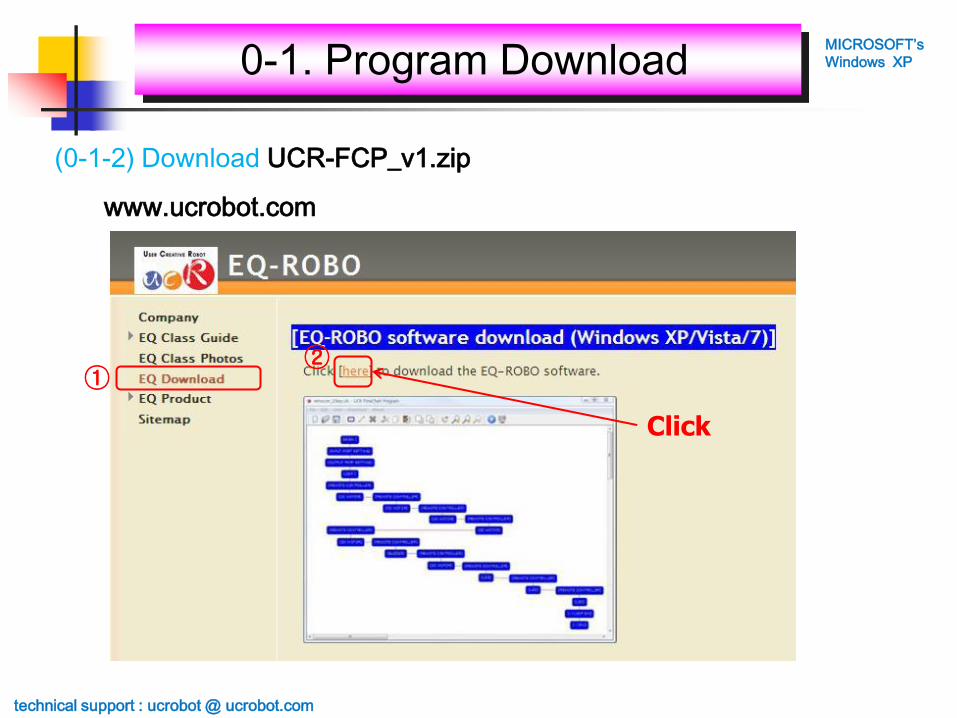
(0-1-2) Download UCR-FCP_v1.zip
MICROSOFT’s
Windows XP
technical support : ucrobot @ ucrobot.com
www.ucrobot.com
①②
Click

0-1. Program Download
(0-1-2-1) Download UCR-FCP_v1.zip
MICROSOFT’s
Windows XP
technical support : ucrobot @ ucrobot.com
Click

0-1. Program Download
(0-1-2-2) Download UCR-FCP_v1.zip
MICROSOFT’s
Windows XP
technical support : ucrobot @ ucrobot.com
Click

0-1. Program Download
(0-1-2-3) Download UCR-FCP_v1.zip
MICROSOFT’s
Windows XP
technical support : ucrobot @ ucrobot.com
Click

0-1. Program Download
(0-1-2-4) Download UCR-FCP_v1.zip
MICROSOFT’s
Windows XP
technical support : ucrobot @ ucrobot.com

0-1. Program DownloadMICROSOFT’s
Windows XP
technical support : ucrobot @ ucrobot.com
www.ucrobot.com
(0-1-3) Download CP210x_VCP_Win_XP_S2K3_Vista_7.exe
Click

0-1. Program Download
(0-1-3-1) Download CP210x_VCP_Win_XP_S2K3_Vista_7.exe
MICROSOFT’s
Windows XP
technical support : ucrobot @ ucrobot.com
Click

0-1. Program Download
(0-1-3-2) Download CP210x_VCP_Win_XP_S2K3_Vista_7.exe
MICROSOFT’s
Windows XP
technical support : ucrobot @ ucrobot.com
Click

0-1. Program Download
(0-1-3-3) Download CP210x_VCP_Win_XP_S2K3_Vista_7.exe
MICROSOFT’s
Windows XP
technical support : ucrobot @ ucrobot.com
Click

0-1. Program Download
(0-1-3-4) Download CP210x_VCP_Win_XP_S2K3_Vista_7.exe
MICROSOFT’s
Windows XP
technical support : ucrobot @ ucrobot.com

1. Before installation the USB driver, disconnect the USB cable
between Robot and PC.
2. Double click the “CP210x_VCP_Win_XP_S2K3_Vista_7 .exe”.
(0-2-1) Install the USB driver
technical support : ucrobot @ ucrobot.com
0-2. Install the USB DriverMICROSOFT’s
Windows XP
Double Click

technical support : ucrobot @ ucrobot.com
0-2. Install the USB DriverMICROSOFT’s
Windows XP
(0-2-2) Install the USB driver
Click

technical support : ucrobot @ ucrobot.com
0-2. Install the USB DriverMICROSOFT’s
Windows XP
(0-2-3) Install the USB driver
② Click
① Select

technical support : ucrobot @ ucrobot.com
0-2. Install the USB DriverMICROSOFT’s
Windows XP
(0-2-4) Install the USB driver
technical support : ucrobot @ ucrobot.com
0-2. Install the USB DriverMICROSOFT’s
Windows XP
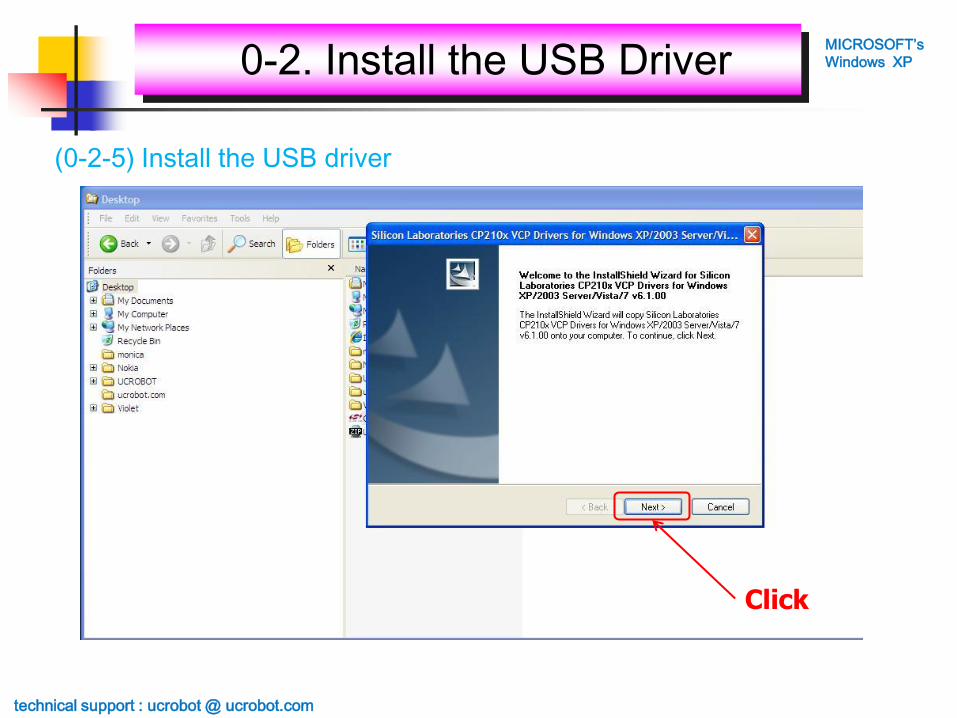
(0-2-5) Install the USB driver
Click

technical support : ucrobot @ ucrobot.com
0-2. Install the USB DriverMICROSOFT’s
Windows XP
(0-2-6) Install the USB driver
Select
technical support : ucrobot @ ucrobot.com
0-2. Install the USB DriverMICROSOFT’s
Windows XP
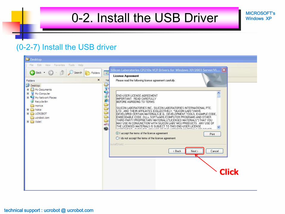
(0-2-7) Install the USB driver
Click
technical support : ucrobot @ ucrobot.com
0-2. Install the USB DriverMICROSOFT’s
Windows XP
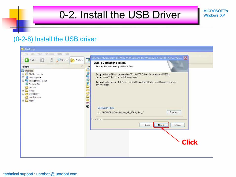
(0-2-8) Install the USB driver
Click

technical support : ucrobot @ ucrobot.com
0-2. Install the USB DriverMICROSOFT’s
Windows XP
(0-2-9) Install the USB driver
Click

technical support : ucrobot @ ucrobot.com
0-2. Install the USB DriverMICROSOFT’s
Windows XP
(0-2-10) Install the USB driver
technical support : ucrobot @ ucrobot.com
0-2. Install the USB DriverMICROSOFT’s
Windows XP
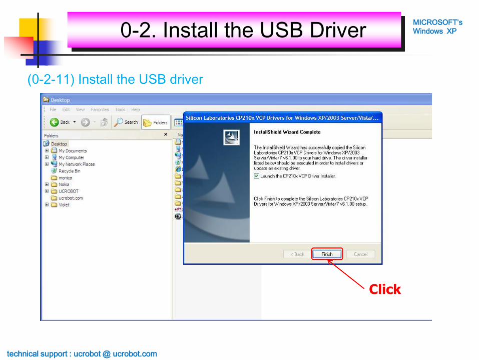
(0-2-11) Install the USB driver
Click

technical support : ucrobot @ ucrobot.com
0-2. Install the USB DriverMICROSOFT’s
Windows XP
(0-2-12) Install the USB driver
Click

technical support : ucrobot @ ucrobot.com
0-2. Install the USB DriverMICROSOFT’s
Windows XP
(0-2-13) Install the USB driver
Click

technical support : ucrobot @ ucrobot.com
0-2. Install the USB DriverMICROSOFT’s
Windows XP
(0-2-14) Install the USB driver

technical support : ucrobot @ ucrobot.com
0-2. Install the USB DriverMICROSOFT’s
Windows XP
(0-2-15) Install the USB driver
Click & Reboot

Connect USB cable
between PC and Mainboard.
If PC detect the USB
device in Mainboard,
LED is on.
technical support : ucrobot @ ucrobot.com
0-3. Set the serial portMICROSOFT’s
Windows XP
(0-3-1) Set the serial port for downloading

1. Open the “Control panel”.
2. Double click the “System”.
You have to set the serial port between COM1 and COM6
because UCR-FCP support only COM1 ~ COM6.
technical support : ucrobot @ ucrobot.com
0-3. Set the serial portMICROSOFT’s
Windows XP
(0-3-2) Set the serial port for downloading

Select the “Hardware” tap.
technical support : ucrobot @ ucrobot.com
0-3. Set the serial portMICROSOFT’s
Windows XP
(0-3-3) Set the serial port for downloading

Click the “Device Manager” button.
technical support : ucrobot @ ucrobot.com
0-3. Set the serial portMICROSOFT’s
Windows XP
(0-3-4) Set the serial port for downloading

Click “Ports (COM & LPT)”
technical support : ucrobot @ ucrobot.com
0-3. Set the serial portMICROSOFT’s
Windows XP
(0-3-5) Set the serial port for downloading

1. You can see the
“USB to UART Bridge” is
assigned to COM7.
※ This is up to your PC.
If “USB to UART Bridge” is
assigned to between COM1
and COM6, stop setting.
2. Double click the
“USB to UART Bridge”.
technical support : ucrobot @ ucrobot.com
0-3. Set the serial portMICROSOFT’s
Windows XP
(0-3-6) Set the serial port for downloading

Select the “Port Settings” tap.
technical support : ucrobot @ ucrobot.com
0-3. Set the serial portMICROSOFT’s
Windows XP
(0-3-7) Set the serial port for downloading

Click the “Advanced…” button.
technical support : ucrobot @ ucrobot.com
0-3. Set the serial portMICROSOFT’s
Windows XP
(0-3-8) Set the serial port for downloading

Change the COM Port Number.
technical support : ucrobot @ ucrobot.com
0-3. Set the serial portMICROSOFT’s
Windows XP
(0-3-9) Set the serial port for downloading

1. Select “COM3” which is not used.
※ It may be different each computer.
You can use one of them which
is not used.
2. Click the “OK” button
to finish setting.
technical support : ucrobot @ ucrobot.com
0-3. Set the serial portMICROSOFT’s
Windows XP
(0-3-10) Set the serial port for downloading

Click
technical support : ucrobot @ ucrobot.com
0-3. Set the serial portMICROSOFT’s
Windows XP
(0-3-11) Set the serial port for downloading

Click “Action” menu and
select the “Scan for hardware changes”
for update the device setting.
technical support : ucrobot @ ucrobot.com
0-3. Set the serial portMICROSOFT’s
Windows XP
(0-3-12) Set the serial port for downloading

1. You can see the changed setting.
2. Finish the “Device Manager” and
“Control Panel” program.
technical support : ucrobot @ ucrobot.com
0-3. Set the serial portMICROSOFT’s
Windows XP
(0-3-13) Set the serial port for downloading

1. Unzip the “UCR-FCP_v1.zip” file.
technical support : ucrobot @ ucrobot.com
0-4. Execute the EQ-ROBOMICROSOFT’s
Windows XP
(0-4-1) Start the UCR-FCP software
2. Double click the “UCR-FCP_v1”
folder.

Double click the “UCR-FCP_v1.exe”
to run the EQ-ROBO.
technical support : ucrobot @ ucrobot.com
0-4. Execute the EQ-ROBOMICROSOFT’s
Windows XP
(0-4-2) Start the UCR-FCP software

Menu
Programming
area
technical support : ucrobot @ ucrobot.com
1. UCR Flowchart ProgramMICROSOFT’s
Windows XP

(2-1-1) Menu bar - File menu
⑤
⑥
①②
③④
① New - make a new program file
② Open – open a program file
③ Save – save a program file
④ Save As – save a program file to new name
⑤ Recent files – recent program file list
⑥ Exit – finish program, UCR-FCP
※ If there is need to save program file when execute the following menu, check
window is pop up.
① New / ② Open / ⑤ Recent files / ⑥ Exit
technical support : ucrobot @ ucrobot.com
2. UCR-FCP MenuMICROSOFT’s
Windows XP

(2-1-①②⑤⑥) File save check window
File save check
window
① save
② not save
③ cancel the command
① ② ③
Current file name
(If current file is not saved, * is displayed)
* If there is new file, file is saved as new name.
technical support : ucrobot @ ucrobot.com
2. UCR-FCP MenuMICROSOFT’s
Windows XP
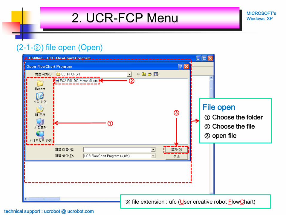
(2-1-②) file open (Open)
File open
① Choose the folder
② Choose the file
③ open file
①
②
③
※ file extension : ufc (User creative robot FlowChart)
technical support : ucrobot @ ucrobot.com
2. UCR-FCP MenuMICROSOFT’s
Windows XP

(2-1-③④) file save (Save) & save as new file (Save As)
File Save
① Choose the folder
② Write the name
③ save the file
①
② ③
technical support : ucrobot @ ucrobot.com
2. UCR-FCP MenuMICROSOFT’s
Windows XP

(2-2) Menu bar – Edit menu
① Add Node – make a new node
② Add Link – make a new link
③ Delete – delete the selected node or link
④ Cut – cut the selected node
⑤ Copy – copy the selected node
⑥ Paste – paste the copied node
⑦ Bring to Front – bring to front the selected node
⑧ Send to Back – send to back the selected node
⑨ Edit Color – change the color of selected node
⑩ Node Functions – set the function of selected node
⑤⑥
①②③④
⑧⑦
⑩⑨
technical support : ucrobot @ ucrobot.com
2. UCR-FCP MenuMICROSOFT’s
Windows XP

(2-2+) Another method to run the “Edit menu”
① Select the node
② Click the right button of
mouse on the selected node.
③ Edit menu is pop up.
④ Select the menu which you want.
①
③
④ Select the menu
② Click the right button of mouse
technical support : ucrobot @ ucrobot.com
2. UCR-FCP MenuMICROSOFT’s
Windows XP

(2-2-①) Make a new node (Add Node)
①
① Click the “Add Node”
② The new node is added at programming area
②
technical support : ucrobot @ ucrobot.com
2. UCR-FCP MenuMICROSOFT’s
Windows XP

(2-2-①+) Select the node
Select the one node
Place the mouse pointer on the node
which is you want to select
and click the left button of mouse.
Select the many nodes
1st method) Pressing the left button of mouse and
grouping nodes which you want to select.
2nd method) Pressing the “ctrl” key and select the node
which you want clicking the left button of
mouse one by one.
technical support : ucrobot @ ucrobot.com
2. UCR-FCP MenuMICROSOFT’s
Windows XP

(2-2-②) Make a new link (Add Link)
①
① Select the two nodes
② Click the “Add Link”
③ The new link is added between selected nodes.
②
technical support : ucrobot @ ucrobot.com
2. UCR-FCP MenuMICROSOFT’s
Windows XP

(2-2-③) Delete the selected node or link (Delete)
①
① Select node and link which you want to delete.
② Click the “Delete”.
②
technical support : ucrobot @ ucrobot.com
2. UCR-FCP MenuMICROSOFT’s
Windows XP

(2-2-④) Cut the selected node (Cut)
①
① Select the node which you want to cut.
② Click the “Cut”.
②
technical support : ucrobot @ ucrobot.com
2. UCR-FCP MenuMICROSOFT’s
Windows XP

(2-2-⑤) Copy the selected node (Copy)
①
① Select the node which you want to copy.
② Click the “Copy”.
②
technical support : ucrobot @ ucrobot.com
2. UCR-FCP MenuMICROSOFT’s
Windows XP

(2-2-⑥) Paste the copied node (Paste)
①
① Click the “Paste”.
② The new node which you copied or cut previously
is added on the programming area.
②
technical support : ucrobot @ ucrobot.com
2. UCR-FCP MenuMICROSOFT’s
Windows XP

(2-2-⑦⑧) Bring to Front / Send to Back
① Bring to Front
① Select the node which you
want to bring to front.
② Click the “Bring to Front”.
③ Selected node is come to front.
② ②
③
Send to Back
① Select the node which you
want to send to back.
② Click the “Send to Back”.
③ Selected node is go to back.
①
③
technical support : ucrobot @ ucrobot.com
2. UCR-FCP MenuMICROSOFT’s
Windows XP

(2-2-⑨) Change the color of selected node (Edit Color)
①
Pop up the “Edit Color”① Select the node.
② Click the right button of mouse
to pop up the “Edit Menu”
③ Select the “Edit Color”.
Property in Edit Color
Ⓐ X position
Ⓑ Y position
Ⓒ Color of Character
Ⓓ Color of out line
Ⓔ Color of back ground
③
②
Ⓒ
Ⓐ
Ⓓ
Ⓑ
Ⓔ
technical support : ucrobot @ ucrobot.com
2. UCR-FCP MenuMICROSOFT’s
Windows XP

(2-2-⑨+) Change the color of selected link (Edit Color)
①
Pop up the “Edit Color”
① Select the link.
② Click the “Edit Menu”.
③ Select the
“Node Color”.
Property in Edit Color
Ⓐ Color of line
②
Ⓐ
technical support : ucrobot @ ucrobot.com
2. UCR-FCP MenuMICROSOFT’s
Windows XP

(2-2-⑩) Set the function of selected node (Node Functions)
Pop up the “Define
Function of Node”
① Select the node.
② Click the right button
of mouse to pop up
the “Edit Menu”
③ Select the
“Node Functions”.
technical support : ucrobot @ ucrobot.com
2. UCR-FCP MenuMICROSOFT’s
Windows XP

(2-2-⑩+) Foretasting the node properties (1)
① “} // IF END”
② “} // ELSE IF END”
③ “} // ELSE END”
④ “} // LOOP END”
⑤ “} // END”
Node has pair is not
activated before starting
node is not defined.
technical support : ucrobot @ ucrobot.com
2. UCR-FCP MenuMICROSOFT’s
Windows XP
①
②
③
④
⑤

(2-2-⑩+) Foretasting the node properties (2)
Node (instruction) description
① Begin and End point of program
-. “BEGIN {” & “} //END”
② Definition the Input/Output of robot
-. “{INPUT PORT SETTING}”
-. “{OUTPUT PORT SETTING}”
③ Condition, Repetition
-. “IF {” & “} //IF END”
-. “ELSE IF {” & “} //ELSE IF END”
-. “ELSE {” & “} //ELSE END”
-. “LOOP {” & “} //LOOP END”
④ Others
-. “{DELAY TIME}”
-. “{REMOTE CONTROLLER}”
-. “{DC MOTOR}”
-. “{SERVO MOTOR}”
-. “{LED}”
-. “{BUZZER}”
① ②
④③
technical support : ucrobot @ ucrobot.com
2. UCR-FCP MenuMICROSOFT’s
Windows XP

(2-3) Menu bar - View menu
① Pan – moving display view
② Zoom In - 120% zoom in the display view
③ Zoom Out - 80% zoom out the display view
④ Zoom All – zoom all the display view
①②③④
Horizontal scroll bar
Vertical scroll bar
※① Pan & ④ Zoom All is supporting at the next version.
technical support : ucrobot @ ucrobot.com
2. UCR-FCP MenuMICROSOFT’s
Windows XP

(2-4) Menu bar - Download menu
① Error Check – Check the error in program
② Download – Download the program into mainboard
①②
※ You can download program into the mainboard
only if there is no error after Error Check
technical support : ucrobot @ ucrobot.com
2. UCR-FCP MenuMICROSOFT’s
Windows XP

(2-4-①) Checking the error in program (Error Check)
Error Check
① Making the program.
② Click the “Error Check”
③ If there is no error in program,
the “Download” button is activated.
①
②
③
※ If there are error in program,
the description window about error is pop up.
technical support : ucrobot @ ucrobot.com
2. UCR-FCP MenuMICROSOFT’s
Windows XP

(2-4-②) Download the program into the mainboard (Download)
Download
① Making the program
② Error check
③ Click the “Download”
④ Download window is pop up
①
③
④
②
technical support : ucrobot @ ucrobot.com
2. UCR-FCP MenuMICROSOFT’s
Windows XP
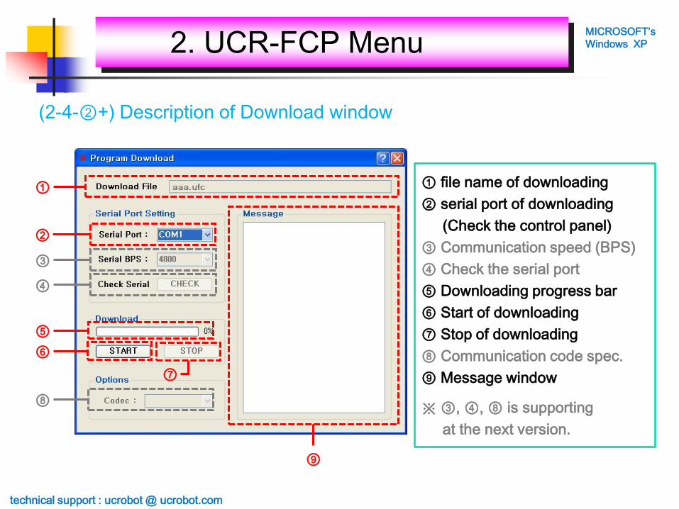
(2-4-②+) Description of Download window
① file name of downloading
② serial port of downloading
(Check the control panel)
③ Communication speed (BPS)
④ Check the serial port
⑤ Downloading progress bar
⑥ Start of downloading
⑦ Stop of downloading
⑧ Communication code spec.
⑨ Message window
※ ③, ④, ⑧ is supporting
at the next version.
②
①
⑨
③
④
⑤
⑥
⑧
⑦
technical support : ucrobot @ ucrobot.com
2. UCR-FCP MenuMICROSOFT’s
Windows XP

(2-5) Menu bar - About menu
technical support : ucrobot @ ucrobot.com
2. UCR-FCP MenuMICROSOFT’s
Windows XP
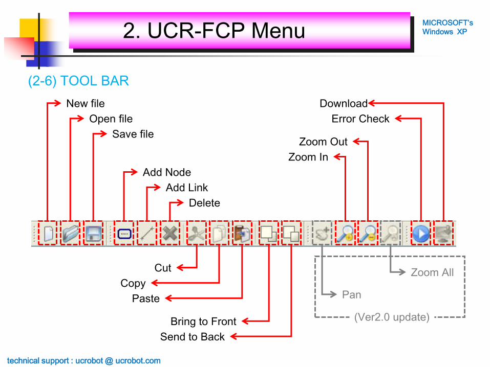
(2-6) TOOL BAR
New file
Open file
Save file
Add Node
Add Link
Delete
Download
Error Check
Zoom Out
Zoom In
Cut
Copy
Paste Pan
Zoom All
Send to Back
Bring to Front (Ver2.0 update)
technical support : ucrobot @ ucrobot.com
2. UCR-FCP MenuMICROSOFT’s
Windows XP

(3-1) Begin & End point of program : “BEGIN {” & “} //END”
[Program Begin]
① Select “Node functions…”
: BEGIN{ / } END
② Select
: PROGRAM BEGIN
[Program END]
① Select “Node functions…”
: BEGIN{ / } END
② Select
: PROGRAM END
※ Program must have begin and end point.
①
②
②
technical support : ucrobot @ ucrobot.com
3. Define Node’s functionMICROSOFT’s
Windows XP

(3-1-ex) Begin & End point of program : “BEGIN {” & “} //END”
Program must start from the “BEGIN {”.
Program must finish using “} //END”.
technical support : ucrobot @ ucrobot.com
3. Define Node’s functionMICROSOFT’s
Windows XP

(3-2-1) Definition the Input of robot : “{INPUT PORT SETTING}”
[Define the Input]① Select the “Node Functions…”
: INPUT PORT SETTING
② Define the Input
ⓐ RCR : Remote Controller
ⓑ IN-1 : IN1 Input
ⓒ IN-2 : IN2 Input
ⓓ IN-3 : IN3 Input
ⓔ IN-4 : IN4 Input
ⓕ IN-5 : IN5 Input
ⓖ IN-6 : IN6 Input
ⓗ IN-7 : IN7 Input
※ Input definition must be same to real input condition of robot. If not, it will maybe wrong operations.
①
②
ⓐ
ⓑ
ⓒ
ⓓ
ⓔ
ⓕ
ⓖ
ⓗ
※ Program must have the
“Input Port Setting”.
technical support : ucrobot @ ucrobot.com
3. Define Node’s functionMICROSOFT’s
Windows XP

(3-2-2) “{INPUT PORT SETTING}”- REMOTE CONTROLLER
[Remote Controller]① INPUT PORT SETTING
② RCR
※ Remote Signal Receiver must be connected to RCR input port of main controller.
①
②
※ RCR can not be selected
together other inputs.
technical support : ucrobot @ ucrobot.com
3. Define Node’s functionMICROSOFT’s
Windows XP
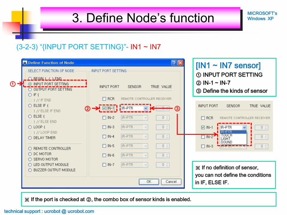
(3-2-3) “{INPUT PORT SETTING}”- IN1 ~ IN7
[IN1 ~ IN7 sensor]① INPUT PORT SETTING
② IN-1 ~ IN-7
③ Define the kinds of sensor
※ If the port is checked at ②, the combo box of sensor kinds is enabled.
①
② ③
※ If no definition of sensor,
you can not define the conditions
in IF, ELSE IF.
technical support : ucrobot @ ucrobot.com
3. Define Node’s functionMICROSOFT’s
Windows XP

(3-2-ex) “{INPUT PORT SETTING}”
If there is no input sensor used, the node is displayed yellow color.
If there is one more sensor definition, the node is displayed blue color.
※ There is no problem if the robot has no sensor.
※ Input definition must be same to real input condition of robot.
If not, it will maybe wrong operations.
technical support : ucrobot @ ucrobot.com
3. Define Node’s functionMICROSOFT’s
Windows XP

(3-3-1) Definition the Output of robot : “{OUTPUT PORT SETTING}”
[Define the Output]① Select the “Node Functions…”
: OUTPUT PORT SETTING
② Define the output
ⓐ OUT-1 : OUT1 Output
ⓑ OUT-2 : OUT2 Output
ⓒ OUT-3 : OUT3 Output
ⓓ OUT-4 : OUT4 Output
ⓔ OUT-5 : OUT5 Output
ⓕ OUT-6 : OUT6 Output
ⓖ OUT-7 : OUT7 Output
※ Output definition must be same to real output condition of robot. If not, it will maybe wrong operations.
①
②
ⓐ
ⓑ
ⓒ
ⓓ
ⓔ
ⓕ
ⓖ ※ DC motors must be connected to
the DC motor connector of main
controller not output port.
technical support : ucrobot @ ucrobot.com
3. Define Node’s functionMICROSOFT’s
Windows XP

(3-3-2) “{OUTPUT PORT SETTING}”- OUT1 ~ OUT7
[OUT1 ~ OUT7 Output]① OUTPUT PORT SETTING
② OUT1 ~ OUT7
③ Define the kinds of Output
※ Initial value of LED and BUZZER is the same as 1, if the value is more than 1.
①
② ③
[Initial value]① LED : 0 or 1
② BUZZER : 0 or 1
③ SERVO MOTOR : 0 ~ 180
technical support : ucrobot @ ucrobot.com
3. Define Node’s functionMICROSOFT’s
Windows XP

(3-3-ex) “{OUTPUT PORT SETTING}”
If there is no output module used, the node is displayed yellow color.
※ There is no problem if the robot has no output module
except DC motors.
If there is one more output module definition,
the node is displayed blue color.
※ Output definition must be same to real output condition of robot.
If not, it will maybe wrong operations.
technical support : ucrobot @ ucrobot.com
3. Define Node’s functionMICROSOFT’s
Windows XP

(3-4-1) Definition the begin point of IF condition : “IF {”
[IF condition]① Select the “Node Functions…”
: IF {
② Define the input condition
ⓐ ID : sequence number
(automatically assigned)
ⓑ CONDITION : AND/OR
ⓒ IN-1 : IN1 input condition
ⓓ IN-2 : IN2 input condition
ⓔ IN-3 : IN3 input condition
ⓕ IN-4 : IN4 input condition
ⓖ IN-5 : IN5 input condition
ⓗ IN-6 : IN6 input condition
ⓘ IN-7 : IN7 input condition
※ The only inputs which were defined at “{INPUT PORT SETTING}” are enabled .
①
②
ⓐ ⓑ
ⓒ ⓓ ⓔ
ⓕ ⓖ ⓗ ⓘ
technical support : ucrobot @ ucrobot.com
3. Define Node’s functionMICROSOFT’s
Windows XP

(3-4-ex1) “IF {”
If there is no defined condition, the node is displayed yellow color.
※ In this case, there is no error during checking the error,
it is meaningless condition.
If there is one more defined condition, the node is displayed blue color.
technical support : ucrobot @ ucrobot.com
3. Define Node’s functionMICROSOFT’s
Windows XP
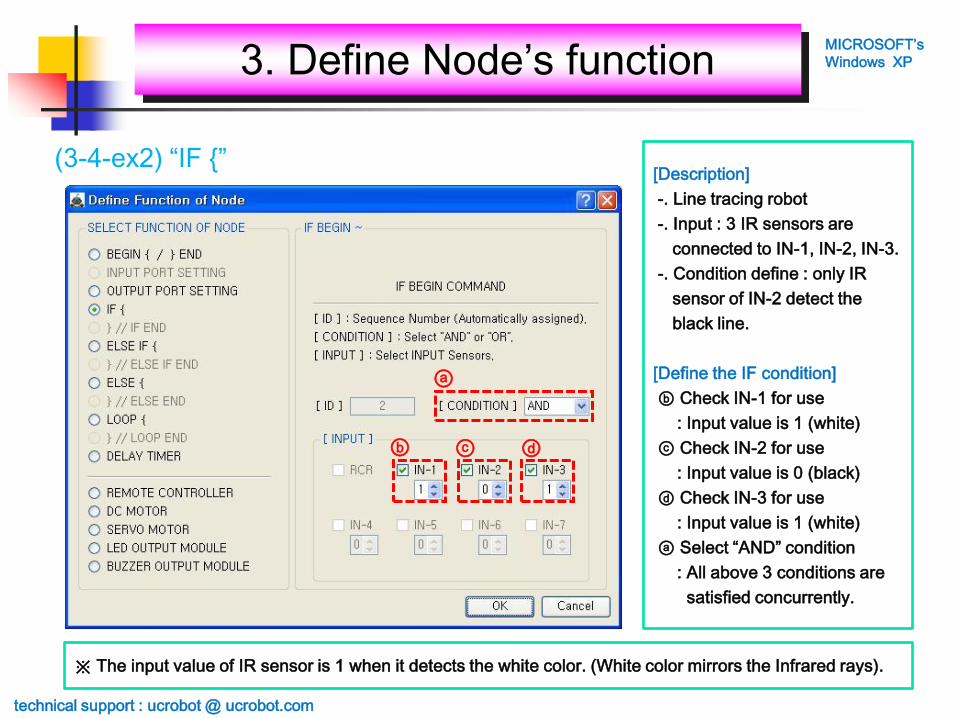
(3-4-ex2) “IF {”[Description]
-. Line tracing robot
-. Input : 3 IR sensors are
connected to IN-1, IN-2, IN-3.
-. Condition define : only IR
sensor of IN-2 detect the
black line.
[Define the IF condition]
ⓑ Check IN-1 for use
: Input value is 1 (white)
ⓒ Check IN-2 for use
: Input value is 0 (black)
ⓓ Check IN-3 for use
: Input value is 1 (white)
ⓐ Select “AND” condition
: All above 3 conditions are
satisfied concurrently.
※ The input value of IR sensor is 1 when it detects the white color. (White color mirrors the Infrared rays).
ⓐ
ⓑ ⓒ ⓓ
technical support : ucrobot @ ucrobot.com
3. Define Node’s functionMICROSOFT’s
Windows XP

OR
(3-4-ex3) “IF {”[Description]
-. Obstacle avoiding robot
-. Input : 3 IR sensors are
connected to IN-1, IN-2, IN-3.
-. Condition define : more than
one of 3 IR sensor detect the
obstacle
[Define the IF condition]
ⓑ Check IN-1 for use
: Input value is 1 (obstacle)
ⓒ Check IN-1 for use
: Input value is 1 (obstacle)
ⓓ Check IN-1 for use
: Input value is 1 (obstacle)
ⓐ Select “OR” condition
: more than one of 3 IR
sensor are satisfied
※ The input value of IR sensor is 1 when it detects obstacle.
(Dark obstacle is not detected because it does not reflect the Infrared rays).
ⓐ
ⓑ ⓒ ⓓ
technical support : ucrobot @ ucrobot.com
3. Define Node’s functionMICROSOFT’s
Windows XP

(3-5-1) Definition the end point of IF condition : “} // IF END”
[IF END condition]① Select the “Node Functions…”
: } // IF END
② Define the ID of “IF {”
ⓐ ID : Sequence number of
paired “IF condition”
※ You must select the corresponding sequence number of “IF {” in “} // IF END”.
①
②
ⓐ
→ It contains automatically
all the sequence numbers of
“IF {“.
Select one matched.
technical support : ucrobot @ ucrobot.com
3. Define Node’s functionMICROSOFT’s
Windows XP

(3-5-ex1) “ IF { ” & “ } // IF END ”
※ Above program is useless because the robot does not operating.
But there is no error because all nodes are defined properly.
Program must start from “{BEGIN}” node.
Program must have “{INPUT PORT SETTING}” node.
If there is no input sensor used, the node is displayed yellow color.
Program must have “{OUTPUT PORT SETTING}” node.
If there is no output module used, the node is displayed yellow color.
There is “IF {” condition, but it is impossible to define the condition
because there is no definition in “{INPUT PORT SETTING}” node.
“} // IF END” is displayed blue color because the sequence number is
defined according to the “IF {” node. If not it is displayed yellow color.
Above “IF {“ does not make an error if condition is not defined,
but “} // IF END” makes an error if the sequence number is not defined.
Program must end with “{END}” node.
technical support : ucrobot @ ucrobot.com
3. Define Node’s functionMICROSOFT’s
Windows XP
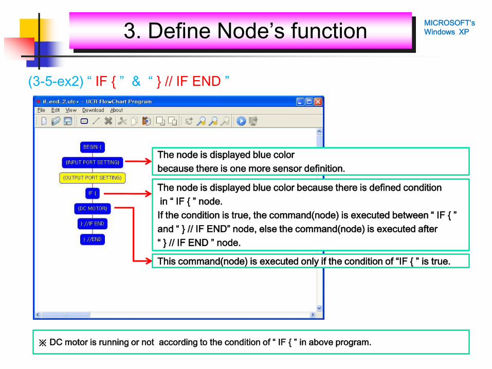
(3-5-ex2) “ IF { ” & “ } // IF END ”
※ DC motor is running or not according to the condition of “ IF { ” in above program.
The node is displayed blue color
because there is one more sensor definition.
The node is displayed blue color because there is defined condition
in “ IF { ” node.
If the condition is true, the command(node) is executed between “ IF { ”
and “ } // IF END” node, else the command(node) is executed after
“ } // IF END ” node.
This command(node) is executed only if the condition of “IF { ” is true.
3. Define Node’s functionMICROSOFT’s
Windows XP

(3-6-1) Definition the begin point of ELSE IF condition : “ELSE IF {”
[ELSE IF condition]
→ same as [IF condition]
※ ELSE IF cannot be used individually, it must be following the IF condition.
①
②
ⓐ ⓑ
ⓒ ⓓ ⓔ
ⓕ ⓖ ⓗ ⓘ
If(condition1) {command1;}
else if(condition2) {command2;}
→ if [condition1] is true
[command1] is executed,
if [condition1] is false and
[condition2] is true
[command2] is executed.
if [condition1] and [condition2]
are false, both [command1] and
[command2] are not executed.
technical support : ucrobot @ ucrobot.com
3. Define Node’s functionMICROSOFT’s
Windows XP

(3-6-ex1) “ELSE IF {”
※ Above program is useless because the robot does not operating.
But there is no error because all nodes are defined properly.
We defined the sequence number of “ELSE IF { ” node at
“ } //ELSE IF END” node, so its color is blue.
Above “ELSE IF {“ does not make an error if condition is not defined,
but “} //ELSE IF END” makes an error if the sequence number is not defined.
“ ELSE IF { ” node must be placed after “ } // IF END ” or
“ } // ELSE IF END ” node.
Although we use “ ELSE IF { ” node, the node color is yellow because
we did not define the input sensor at “ {INPUT PORT SETTING} ”
so we can not define the condition in “ELSE IF {“ node.
technical support : ucrobot @ ucrobot.com
3. Define Node’s functionMICROSOFT’s
Windows XP

(3-7-1) Definition the end point of ELSE IF condition : “} // ELSE IF”
[“} //ELSE IF” condition]
→ same as [“} // IF” condition]
※ You must select the corresponding sequence number of “ELSE IF {” in “} //ELSE IF END”.
①
②
ⓐIf(condition1) {command1;}
else if (condition2) {command2;}
else if (condition3) {command3;}
…
→ If you have many conditions,
you can check all conditions
using “else if” as above.
technical support : ucrobot @ ucrobot.com
3. Define Node’s functionMICROSOFT’s
Windows XP

(3-7-ex1) “} // ELSE IF”
※ Above program is useless because the robot does not operating.
But there is no error because all nodes are defined properly.
technical support : ucrobot @ ucrobot.com
3. Define Node’s functionMICROSOFT’s
Windows XP
If(condition1) {command1;}
else if (condition2) {command2;}
else if (condition3) {command3;}
…
→ If you have many conditions,
you can check all conditions
using “else if” as above.
1st condition
2nd condition
3rd condition

(3-8-1) Definition the begin point of ELSE condition : “ELSE {”
[ELSE condition]
① Select the “Node Functions…”
: ELSE {
② Define the function
ⓐ ID : sequence number
(automatically assigned)
※ ELSE cannot be used individually, it must be following the IF or ELSE IF condition.
①
②
ⓐ
If (condition1) {command1;}
else {command2; }
→ If [condition1] is true,
[command1] is executed,
else (if [condition1] is false),
[command2] is executed.
technical support : ucrobot @ ucrobot.com
3. Define Node’s functionMICROSOFT’s
Windows XP

(3-8-ex1) “ELSE {”
※ ELSE cannot be used individually, it must be following the IF or ELSE IF condition.
“} //ELSE END” makes an error if the sequence number is not defined.
“ ELSE { ” node must be placed after “ } // IF END ” or
“ } // ELSE IF END ” node.
“ ELSE { ” is executed only if the “IF {” or “ELSE IF {” is not true.
“ ELSE { ” node is displayed blue color always.
technical support : ucrobot @ ucrobot.com
3. Define Node’s functionMICROSOFT’s
Windows XP

(3-9-1) Definition the end point of ELSE condition : “} // ELSE END”
[“} // ELSE END” condition]
① Select the “Node Functions…”
: } // ELSE END
② Define the ID of “ELSE {”
ⓐ ID : Sequence number of
paired “ELSE condition”
※ You must select the corresponding sequence number of “ELSE {” in “} // ELSE END”.
①
②ⓐ
If (condition1) {command1;}
else if (condition2) {command2;}
else {command3;}
→ If you have 3 conditions to
check, you can use “if”, “else if”
and “else” condition.
technical support : ucrobot @ ucrobot.com
3. Define Node’s functionMICROSOFT’s
Windows XP

(3-9-ex1) “} // ELSE”
※ ELSE cannot be used individually, it must be following the IF or ELSE IF condition.
technical support : ucrobot @ ucrobot.com
3. Define Node’s functionMICROSOFT’s
Windows XP
1st condition
2nd condition
3rd condition
If (condition1) {command1;}
else if (condition2) {command2;}
else {command3;}
→ If you have 3 conditions to
check, you can use “if”, “else if”
and “else” condition.
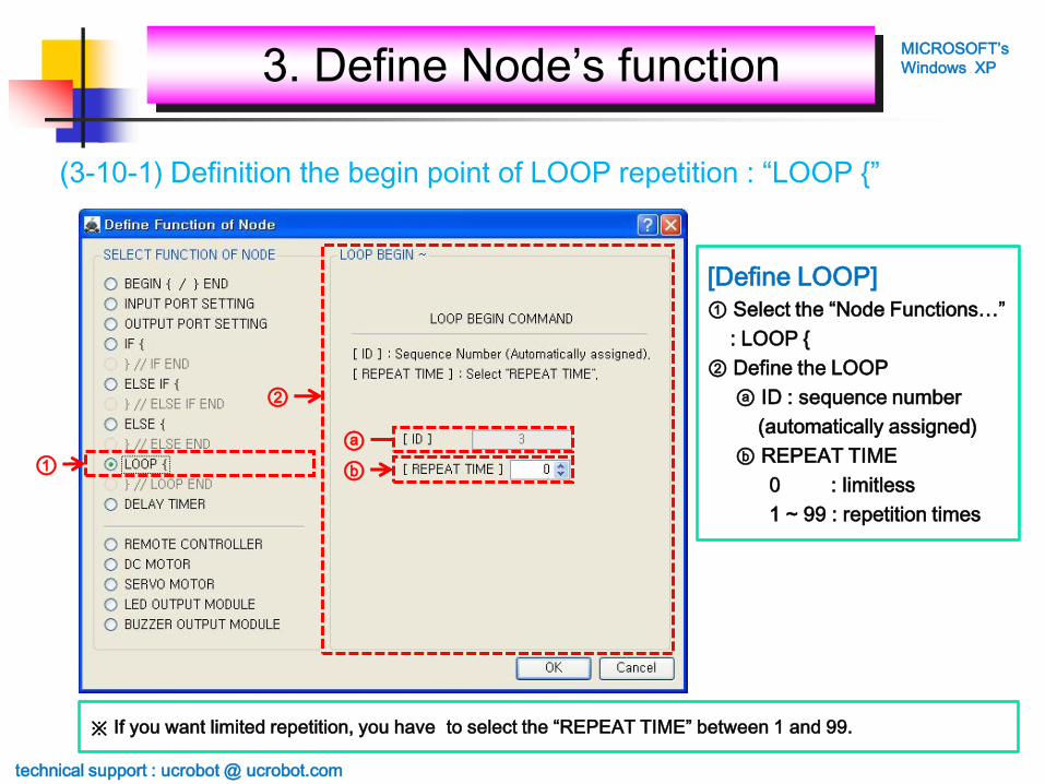
(3-10-1) Definition the begin point of LOOP repetition : “LOOP {”
[Define LOOP]
① Select the “Node Functions…”
: LOOP {
② Define the LOOP
ⓐ ID : sequence number
(automatically assigned)
ⓑ REPEAT TIME
0 : limitless
1 ~ 99 : repetition times
※ If you want limited repetition, you have to select the “REPEAT TIME” between 1 and 99.
①
②
ⓐ
ⓑ
technical support : ucrobot @ ucrobot.com
3. Define Node’s functionMICROSOFT’s
Windows XP

(3-10-ex1) “LOOP {”
Loop (repetition time)
{
command;
}
→ Repeat the command
according to the repetition
time.
※ Above program is useless because the robot does not operating.
But there is no error because all nodes are defined properly.
technical support : ucrobot @ ucrobot.com
3. Define Node’s functionMICROSOFT’s
Windows XP

(3-11-1) Definition the end point of LOOP : “} // LOOP END”
[LOOP END]
① Select the “Node Functions…”
: } // LOOP END
② Define the ID of “LOOP {”
ⓐ ID : Sequence number of
paired “LOOP {”
※ You must select the corresponding sequence number of “LOOP {” in “} // LOOP END”.
①
②ⓐ
technical support : ucrobot @ ucrobot.com
3. Define Node’s functionMICROSOFT’s
Windows XP

(3-11-ex1) “} // LOOP END”
Loop1 (repetition time1)
{
command1;
Loop2 (repetition time2)
{
command2;
}
}
→ While [command1] is executed,
[command2] is executed
repetition time2.
That is to say, [command2] is
executed totally repetition
time1 * repetition time2.
※ Above program is useless because the robot does not operating.
But there is no error because all nodes are defined properly.
Loop2 Loop1
technical support : ucrobot @ ucrobot.com
3. Define Node’s functionMICROSOFT’s
Windows XP

(3-12-1) DELAY TIMER : “{DELAY TIMER}”
[DELAY TIMER ]
① Select the “Node Functions…”
: DELAY TIMER
② Define the function
ⓐ Define the delay time
-. Min. : 0 => 0 second
-. Max. : 200 => 20.0 second
①
②ⓐ
technical support : ucrobot @ ucrobot.com
3. Define Node’s functionMICROSOFT’s
Windows XP

(3-12-ex1) “{DELAY TIMER}”
Set the output module LED in “ {OUTPUT PORT SETTING} node.
Set the “ {LED} ” node. Ex) LED is 2 times blinking on OUT1
Set the “ {LED} ” node. Ex) LED is 1 time blinking on OUT2
Set the “ {DELAY} ” node. Ex) All operation is stopping for 1 second.
technical support : ucrobot @ ucrobot.com
3. Define Node’s functionMICROSOFT’s
Windows XP

(3-13-1) REMOTE CONTROLLER : “ {REMOTE CONTROLLER} ”
[REMOTE CONTROLLER]
① Select the “Node Functions…”
: REMOTE CONTROLLER
② Define the Key assignment
※ If you click the Key you want, it is selected.
①
②
ⓐ
ⓑ ⓓ
ⓒ
ⓔ
ⓗ
ⓕ
ⓘ
ⓖ
ⓙ
ⓚⓛ ⓜ
ⓝⓑ
ⓐ ⓒ
ⓓ
ⓔ
ⓗ
ⓕ
ⓘ
ⓖ
ⓙ
※ [DIRECTION MIXED KEY] are
supporting from next version.
technical support : ucrobot @ ucrobot.com
3. Define Node’s functionMICROSOFT’s
Windows XP

(3-13-ex1) “ {REMOTE CONTROLLER} ”
Check the “RCR” in “ {INPUT PORT SETTING} ” node.
We have to use the limitless “LOOP” because robot wait the remote
controller’s key input continuously.
Select the Key you want to use. Ex) “F1” Key
Set the operation of DC motor.
Ex) Left DC Motor : forward direction, speed 100 during 1 second
technical support : ucrobot @ ucrobot.com
3. Define Node’s functionMICROSOFT’s
Windows XP

(3-14-1) DC MOTOR : “ {DC MOTOR} ”
[DC MOTOR]
① Select the “Node Functions…”
: DC MOTOR
② Define the function
ⓐ Left DC Motor’s Direction
ⓑ Right DC Motor’s Direction
-. FORWARD
-. BACKWARD
ⓒ Left DC Motor’s speed
ⓓ Right DC Motor’s speed
-. Min. : 0
-. Max. : 100
ⓔ Operating time
-. Min. : 0 => 0 second
-. Max. : 80 => 8.0 second
※ The real direction of DC motor is decided by the connection direction of DC motor and main controller.
①
②ⓐ ⓑ
ⓓⓒ
ⓔ
technical support : ucrobot @ ucrobot.com
3. Define Node’s functionMICROSOFT’s
Windows XP

(3-14-ex1) “ {DC MOTOR} ”
[DC MOTOR ]
① Motor : Left DC Motor
② Direction : Forward
③ Speed : 100
④ Op. time : 1초
If you want not to use,
you have to set the speed as 0.
①
②
③
④
※ DC motor has no relation to the “ {OUTPUT PORT SETTING} ” node setting.
technical support : ucrobot @ ucrobot.com
3. Define Node’s functionMICROSOFT’s
Windows XP

(3-14-ex2) “ {DC MOTOR} ”
[forward direction
/ speed 100 during 3 second]
① Motor : Both DC Motor
② Direction : Forward
③ Speed : 100
④ Op. time : 3 seconds
①
②
③
④
technical support : ucrobot @ ucrobot.com
3. Define Node’s functionMICROSOFT’s
Windows XP

(3-14-ex3) “ {DC MOTOR} ”
[Spin with 100 speed
for 5 seconds.]
① Motor : Both DC Motor
② Direction
- Left DC Motor : Backward
- Right DC Motor : Forward
③ Speed : 100
④ Op. time : 5 seconds
①
②
③
④
technical support : ucrobot @ ucrobot.com
3. Define Node’s functionMICROSOFT’s
Windows XP

[SERVO MOTOR ]
① Select the “Node Functions…”
: SERVO MOTOR
② Define the function
ⓐ Select the output ports of
Servo motor
ⓑ Target angle (0~180)
※ The angle of above photo is based on the face of “User Creative Robot” engraved.
①
②
ⓐ ⓑ
(3-15-1) SERVO MOTOR : “ {SERVO MOTOR} ”
0 degree 180 degree
90 degree
technical support : ucrobot @ ucrobot.com
3. Define Node’s functionMICROSOFT’s
Windows XP

(3-15-ex1) “ {SERVO MOTOR} ”
[Setting the angle of
Servo motor on OUT1 ~ 7]
① OUT1 Servo : 15 degree
② OUT2 Servo : 30 degree
③ OUT3 Servo : 45 degree
④ OUT4 Servo : 60 degree
⑤ OUT5 Servo : 90 degree
⑥ OUT6 Servo : 135 degree
⑦ OUT7 Servo : 180 degree
①
②
③
④
⑤
⑥
⑦
※ If the output port is not defined at “ {OUTPUT PORT SETTING} ”, you can’t select the port of Servo motor.
technical support : ucrobot @ ucrobot.com
3. Define Node’s functionMICROSOFT’s
Windows XP

(3-16-1) LED OUTPUT MODULE : “ {LED OUTPUT MODULE} ”
[LED Module]
① Select the “Node Functions…”
: LED OUTPUT MODULE
② Define the function
ⓐ Select the output port
ⓑ LED on time
ⓒ LED off time
-. 5 : 0.5 second
-. 10 : 1.0 second
-. 15 : 1.5 second
-. 20 : 2.0 second
ⓓ LED on/off times
-. 0 ~ 10
(If you select 0,
LED does not turn on.)
※ If the output port is not defined at “ {OUTPUT PORT SETTING} ”, you can’t select the port of LED module.
①
②
ⓐⓑ ⓒ ⓓ
technical support : ucrobot @ ucrobot.com
3. Define Node’s functionMICROSOFT’s
Windows XP

(3-16-ex1) “ {LED OUTPUT MODULE} ”
[LED1-OUT1, LED2-OUT2
on time : 0.5 second
off time : 0.5 second
repetition : 2 times]
① select the OUT-1
② select the OUT-2
③ select the 5 for 0.5 second
at on time
④ select the 5 for 0.5 second
at off time
⑤ select the 2 at repeat
①
②
③ ④ ⑤
※ If the output port is not defined at “ {OUTPUT PORT SETTING} ”, you can’t select the port of LED module.
※ LED modules are connected
to the OUT1 and OUT2 of
main controller.
technical support : ucrobot @ ucrobot.com
3. Define Node’s functionMICROSOFT’s
Windows XP

(3-17-1) BUZZER OUTPUT MODULE : “ {BUZZER OUTPUT MODULE} ”
①
②
ⓐⓑ ⓒ ⓓ
[BUZZER Module]
① Select the “Node Functions…”
: BUZZER OUTPUT MODULE
② Define the function
ⓐ Select the output port
ⓑ BUZZER on time
ⓒ BUZZER off time
-. 5 : 0.5 second
-. 10 : 1.0 second
-. 15 : 1.5 second
-. 20 : 2.0 second
ⓓ BUZZER on/off times
-. 0 ~ 10
(If you select 0, BUZZER
does not turn on.)
※ If the output port is not defined at “ OUTPUT PORT SETTING}”, you can’t select the port of BUZZER module.
technical support : ucrobot @ ucrobot.com
3. Define Node’s functionMICROSOFT’s
Windows XP

(3-16-ex1) “ {LED OUTPUT MODULE} ”
[BUZZER1-OUT7,
on time : 0.5 second
off time : 0.5 second
repetition : 1 time
① select the OUT-7
② select the 5 for 0.5 second
at on time
④ select the 5 for 0.5 second
at off time
⑤ select the 1 at repeat①
② ③ ④
※ If the output port is not defined at “ OUTPUT PORT SETTING}”, you can’t select the port of BUZZER module.
※ BUZZER modules are
connected to the OUT7
of main controller.
technical support : ucrobot @ ucrobot.com
3. Define Node’s functionMICROSOFT’s
Windows XP

(4-1) Making a program and save
Program must start from “{BEGIN}” node.
Program must end with “{END}” node.
Program must have “{INPUT PORT SETTING}” node.
Program must have “{OUTPUT PORT SETTING}” node.
1. Make a program.
2. Save a program.
DC Motor (forward, speed 100, OP time 1 second)
technical support : ucrobot @ ucrobot.com
4. Program downloadMICROSOFT’s
Windows XP

(4-2) Check the error of program
3. Check error.
If there is no error,
this window is pop up.
4. Click “OK”
technical support : ucrobot @ ucrobot.com
4. Program downloadMICROSOFT’s
Windows XP

(4-3) Download icon is enabled
If there is no error,
download icon is enabled.
technical support : ucrobot @ ucrobot.com
4. Program downloadMICROSOFT’s
Windows XP

(4-4) Connect main controller to your computer
5. Connect main controller
to your computer using
USB cable.
If your computer detect the
USB communication from
main controller,
this LED is on.
6. Power on
the main controller
technical support : ucrobot @ ucrobot.com
4. Program downloadMICROSOFT’s
Windows XP

(4-5) Prepare the main controller for downloading the program
7. Select “UP” mode pressing [MODE] button of
main controller.
8. Press [RUN] button of main controller to execute
the “DOWNLOAD” mode.
9. Press [RUN] button again to execute the
“DOWNLOAD” ready state.
“DOWNLOAD” is blinking 2 times.
technical support : ucrobot @ ucrobot.com
4. Program downloadMICROSOFT’s
Windows XP

(4-6) Download window is pop up
10. Click the download
icon.
Download window
is pop up
technical support : ucrobot @ ucrobot.com
4. Program downloadMICROSOFT’s
Windows XP
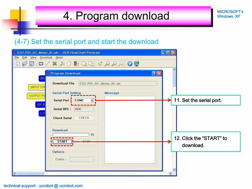
(4-7) Set the serial port and start the download
11. Set the serial port.
12. Click the “START” to
download.
technical support : ucrobot @ ucrobot.com
4. Program downloadMICROSOFT’s
Windows XP

(4-8) Downloading – Delete the EEPROM data from main controller
Serial port : COM2
To save the program data on
main controller,
before downloading delete
the EEPROM data at first.
If download does not start
within 10 second,
main controller is not ready.
Please check again the 4-5.
technical support : ucrobot @ ucrobot.com
4. Program downloadMICROSOFT’s
Windows XP

(4-9) Downloading success
Download is finished.
Run your program !!!
technical support : ucrobot @ ucrobot.com
4. Program downloadMICROSOFT’s
Windows XP

(4-10) Checking the downloading on main controller
“ING ” is displayed during downloading the program
from computer to main controller.
“OK” is displayed after finishing the download.
13. Press [RESET] button to initialize the main controller.
technical support : ucrobot @ ucrobot.com
4. Program downloadMICROSOFT’s
Windows XP

(4-11) Run the downloaded program on main controller
14. Press [RUN] button of main controller to execute
the “DOWNLOAD” mode.
15. Press [MODE] button of main controller to execute
the “OK” mode.
16. Press [RUN] button of main controller to execute
the program downloaded.
“OK” is blinking 2 times and run the program.
※ If you want to re-execute the program, press [RESET] button and do 15 ~ 16.
technical support : ucrobot @ ucrobot.com
4. Program downloadMICROSOFT’s
Windows XP