equestrian trail guidelines for construction and maintenance management... · of missouri-columbia,...
TRANSCRIPT
Equestrian Trail G u i d E l i n E s
FOR COnsTRuCTiOn A nd M AinTEnAnCE

Copyright © 2007 by the Conservation Commission of the State of Missouri
Published by the Missouri Department of Conservation, P.O. Box 180, Jefferson City, Missouri 65102-0180
www.missouriconservation.org
Equal opportunity to participate in and benefit from programs of the Missouri Department of Conservation is available to all individuals without regard to their race, color, national origin, sex, age or disability. Questions should be directed to the Department of Conservation, P.O. Box 180, Jefferson City, MO 65102, (573) 751-4115 (voice) or 800-735-2966 (TTY), or to the U.S. Fish and Wildlife Service Division of Federal Assistance, 4401 N. Fairfax Drive, Mail Stop: MBSP-4020, Arlington, VA 22203.
1
Equestrian Trail G u i d E l i n E s
FOR COnsTRuCTiOn A nd M AinTEnAnCE
Nathan Kyle TaborKathleen M. Trauth, Ph.D., P.E.
George W. Hartman, certified wildlife biologist

2
ACK N OWLED G M ENT S
This publication is the result of a graduate engineering study at the university of Missouri-Columbia, with support and input by land managers within the Missouri department of Conservation (MdC). Partial funding for the study and this publication came from a Recreational Trails Program grant recommended for funding by the Missouri Trails Advisory Board. Funding was provided by the Federal Highway Administration and the Missouri department of natural Resources. The authors thank the land management biologists and foresters of MdC and both the MdC and the Recreational Trails Program for allowing these guides to become a reality.
Missouri Department of Natural Resources

3
table o f co ntent s
Introduction ............................................................................................................................................... 4
chapter 1—degradation of Equestrian Trails ............................................................................................. 5
chapter 2—Techniques for Creating sustainable Trails .............................................................................. 7
A—Trail layout: Preventing Water From Getting on Trails ............................................................ 7
B—Water-diversion structures and Trail-surface shape: Removing Water From Trails ................ 12
C—The Right Wearing surface: Hardening the Trail surface ....................................................... 16
chapter 3—Fixing Abandoned Trails: How to Close and Rehabilitate Old Trails or Trail segments ......... 20
chapter 4—design Procedures: How to design a new Trail or Correct an Existing Trail Problem .......... 21
chapter 5—Construction Procedures ....................................................................................................... 26
appendix a—Horse and Rider Behaviors ................................................................................................. 32
appendix b—determining soil Texture—Field Method .......................................................................... 33
appendix c—MdC Engineering drawings .............................................................................................. 34
appendix D—Trail Cost Estimates ........................................................................................................... 46
PLEASE NOTE: Once you understand the information in the first three chapters, you can start with Chapter 4 to design trails or correct problems on existing trails. Without understanding the soils, topographic and engineering concepts, Chapter 4 will be confusing and may not provide the design guidance you desire.

4
IntRo DUc tI o n
Missouri is a horse rich state, with a herd size that is the seventh highest in the nation. Missourians owned more than 281,000 horses valued at $420 million in 2005. More than 145,000 of these horses
were used primarily for recreational riding. The total economic impact of these recreational users has been valued at $673 million (American Horse Council Foundation, 2005).
Recreational trail riding is the premier pastime of most of our state’s recreational horse owners. Equestrian trails on state and federally owned lands provide countless hours of relaxation and enjoyment. unfortunately, most equestrian trail development has come about in one of two ways: 1) through the formalization of existing trails created by riders who have meandered through an area or 2) through the designation of trails along existing traces such as old roadways or logging roads. neither method of trail establishment considers soil types, slopes or erosion hazards. neither did managers consider the behavior of trail riders in going around wet spots, deep ruts and fallen trees, thus creating braided trail networks and an ever-expanding corridor for the trail. Equestrian trail maintenance also has not been a high priority as agency budgets are reduced and external funding sources become more scarce. All these factors—throughout decades of trail use—have created a system of trails that has deteriorated beyond acceptable limits by both trail riders and the government agencies that manage the trails.
such was the case within the Missouri department of Conservation (MdC) in autumn 2003. land managers realized the need for well-designed trails and effective trail maintenance standards, because equestrian trail-riding activity has increased during the past several years and deterioration of existing trails has accelerated. To address this problem, MdC land managers requested help in determining the best sites and maintenance techniques for managing equestrian trails.
A graduate study, completed in 2007, used engineering expertise from the department of Civil and Environmental Engineering at the university of Missouri-Columbia. That study is the basis for the guidelines within, which are intended as an aid to land managers within MdC and other Missouri land-management agencies. This study examined soil associations and topographic features found in this state. university and MdC engineering staff provided input and guidance throughout the project. Major trail renovations and design features still will require the expertise of engineers. However, by using the information here, land management personnel should be able to devise basic trail layouts and resolve problem areas within a trail system.
The design of trails based upon soils and topography is basic to erosion control and lower maintenance costs. However, as with any user group, trail riders have behavioral preferences for themselves and their horses that also need to be considered within a trail management program. A partial list of behavioral topics to consider along with the engineering aspects for the trail system is included in Appendix A. This list is not extensive, so managers are encouraged to incorporate area users or organized horse trail groups in the trail-planning process. The best-designed and best-constructed trail system is for naught if riders will not use or stay on the trails.
The information gained by this two-year study was greatly enhanced by and drew heavily upon prior work reported by the usdA Forest service—Hoosier national Forest (HnF) and by the international Mountain Biking Association (iMBA). Although iMBA trails information pertains to mountain bike trails, much of the information they have published is applicable to equestrian trails. The HnF study was conducted during a seven-year period by the Virginia Polytechnic institute and state university department of Forestry.
other recommended trail-building references:Trail Solutions: IMBA’s Guide to Building Sweet Singletrack Available at www.imba.com/resources/trail_building/Natural Surface Trails by Design. 2004. Troy scott Parker. naturescape. Boulder, ColoradoTrail Construction and Maintenance Notebook usdA Forest service, 4E42A25-Trail notebookGeosynthetics for Trails in Wet Areas. 2000. s. Monlux and B. Vachowski. usdA Forest service Technical Report 0023-2838-MTdC
5
cHaP teR 1 D eG R aDatI o n o f eQUe s tR Ian tR aIl s
Trail degradation consists of two problems: soil
erosion and unstable trail surfaces. users tend to avoid trouble sites (muddy areas, for instance) and widen the trail, effectively disturbing more area for subsequent erosion.
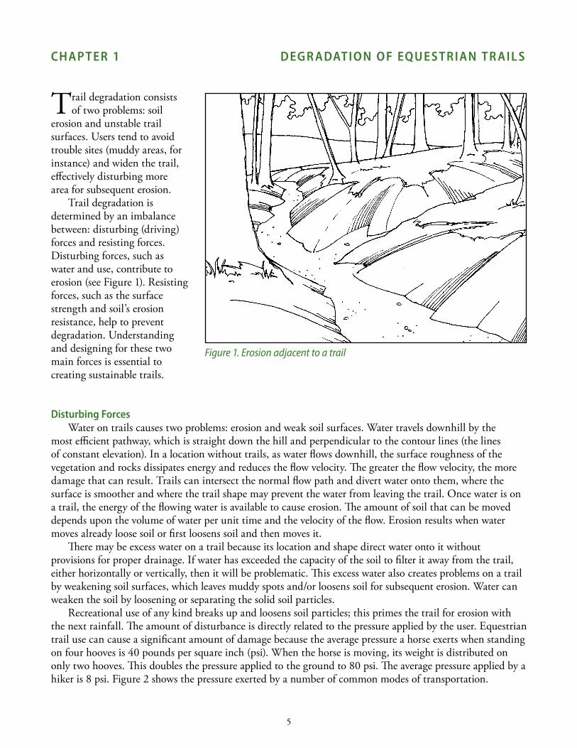
Trail degradation is determined by an imbalance between: disturbing (driving) forces and resisting forces. disturbing forces, such as water and use, contribute to erosion (see Figure 1). Resisting forces, such as the surface strength and soil’s erosion resistance, help to prevent degradation. understanding and designing for these two main forces is essential to creating sustainable trails.
Disturbing forces Water on trails causes two problems: erosion and weak soil surfaces. Water travels downhill by the
most efficient pathway, which is straight down the hill and perpendicular to the contour lines (the lines of constant elevation). in a location without trails, as water flows downhill, the surface roughness of the vegetation and rocks dissipates energy and reduces the flow velocity. The greater the flow velocity, the more damage that can result. Trails can intersect the normal flow path and divert water onto them, where the surface is smoother and where the trail shape may prevent the water from leaving the trail. Once water is on a trail, the energy of the flowing water is available to cause erosion. The amount of soil that can be moved depends upon the volume of water per unit time and the velocity of the flow. Erosion results when water moves already loose soil or first loosens soil and then moves it.
There may be excess water on a trail because its location and shape direct water onto it without provisions for proper drainage. if water has exceeded the capacity of the soil to filter it away from the trail, either horizontally or vertically, then it will be problematic. This excess water also creates problems on a trail by weakening soil surfaces, which leaves muddy spots and/or loosens soil for subsequent erosion. Water can weaken the soil by loosening or separating the solid soil particles.
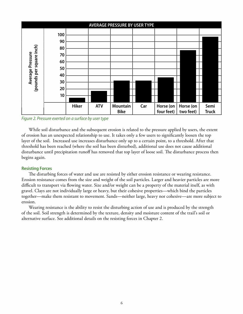
Recreational use of any kind breaks up and loosens soil particles; this primes the trail for erosion with the next rainfall. The amount of disturbance is directly related to the pressure applied by the user. Equestrian trail use can cause a significant amount of damage because the average pressure a horse exerts when standing on four hooves is 40 pounds per square inch (psi). When the horse is moving, its weight is distributed on only two hooves. This doubles the pressure applied to the ground to 80 psi. The average pressure applied by a hiker is 8 psi. Figure 2 shows the pressure exerted by a number of common modes of transportation.
Figure 1. Erosion adjacent to a trail
6
Figure 2. Pressure exerted on a surface by user type
While soil disturbance and the subsequent erosion is related to the pressure applied by users, the extent of erosion has an unexpected relationship to use. it takes only a few users to significantly loosen the top layer of the soil. increased use increases disturbance only up to a certain point, to a threshold. After that threshold has been reached (where the soil has been disturbed), additional use does not cause additional disturbance until precipitation runoff has removed that top layer of loose soil. The disturbance process then begins again.
Resisting forces The disturbing forces of water and use are resisted by either erosion resistance or wearing resistance.
Erosion resistance comes from the size and weight of the soil particles. larger and heavier particles are more difficult to transport via flowing water. size and/or weight can be a property of the material itself, as with gravel. Clays are not individually large or heavy, but their cohesive properties—which bind the particles together—make them resistant to movement. sands—neither large, heavy nor cohesive—are more subject to erosion.
Wearing resistance is the ability to resist the disturbing action of use and is produced by the strength of the soil. soil strength is determined by the texture, density and moisture content of the trail’s soil or alternative surface. see additional details on the resisting forces in Chapter 2.
aVeRaGe PRessURe bY UseR tYPe
100908070605040302010
Hiker atV Mountain bike
car Horse (on four feet)
Horse (on two feet)
semitruck
aver
age
Pres
sure
(pou
nds
per s
quar
e in
ch)
7
cHaP teR 2 tecH n I QUe s fo R cR e atInG sUs taInable tR aIl s
Water can weaken soil and provide the means by which erosion takes place. in order to prevent erosion and the creation of an unstable trail surface, water must be managed. Management curbs excessive
water from getting on a trail and provides a means for water that gets onto a trail to be removed. Effective water management requires proper trail placement, positioning and surface shaping. Water-
diverting structures along the trail are necessary, as well.Trail surfaces also can be hardened to reduce the erosive power of water on a trail before it is diverted.
a. tRaIl laYoUt: PReVentInG WateR fRoM GettInG on tRaIls Trail layout determines the path that a trail takes across the landscape. it includes trail alignment,
steepness or slope, tread length, landscape location and soil type. Because the amount of water on a trail is controlled by the layout, the greater the distance that water flows on it, the greater the potential for degradation. likewise, the greater the volume of water that affects a trail, the higher the potential for degradation. if water can be properly controlled, erosion and degradation can be minimized.
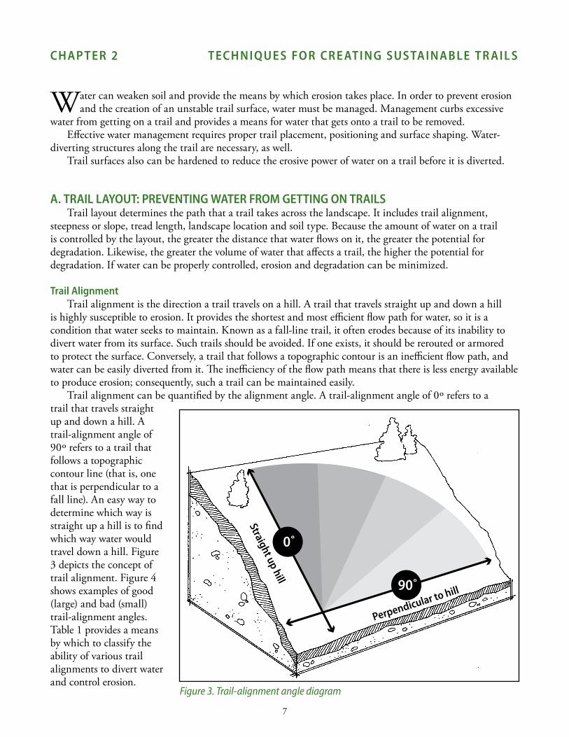
trail alignmentTrail alignment is the direction a trail travels on a hill. A trail that travels straight up and down a hill
is highly susceptible to erosion. it provides the shortest and most efficient flow path for water, so it is a condition that water seeks to maintain. Known as a fall-line trail, it often erodes because of its inability to divert water from its surface. such trails should be avoided. if one exists, it should be rerouted or armored to protect the surface. Conversely, a trail that follows a topographic contour is an inefficient flow path, and water can be easily diverted from it. The inefficiency of the flow path means that there is less energy available to produce erosion; consequently, such a trail can be maintained easily.
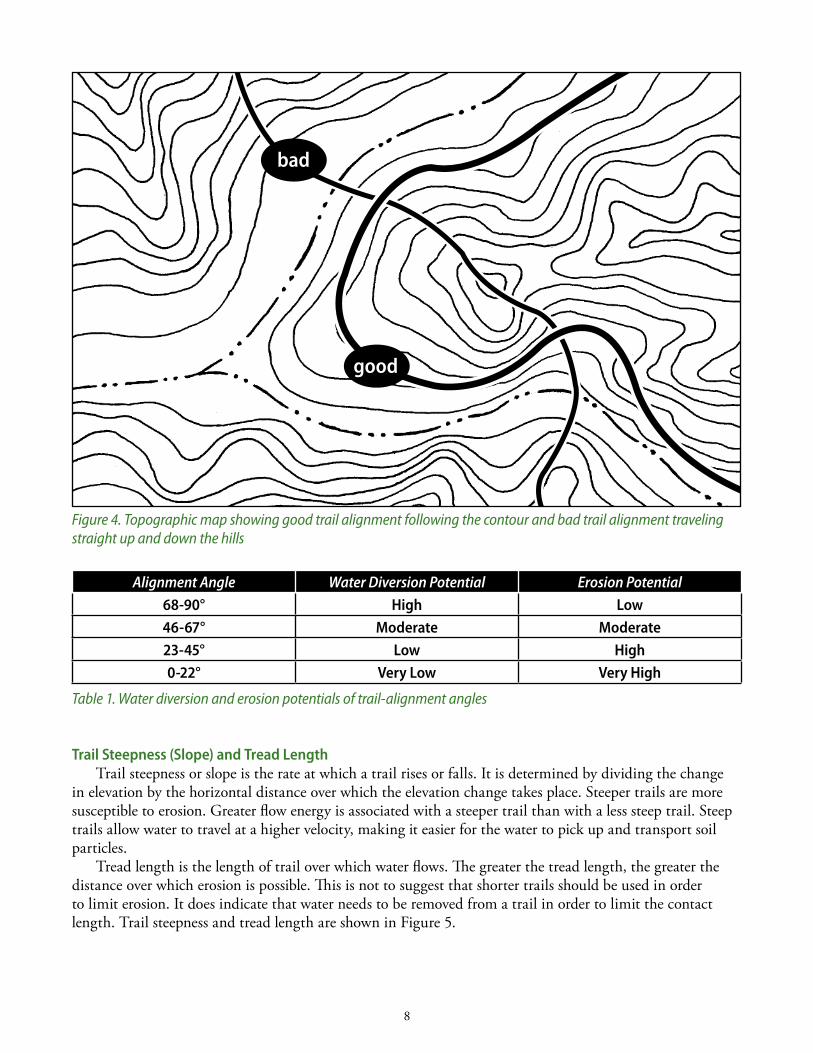
Trail alignment can be quantified by the alignment angle. A trail-alignment angle of 0º refers to a trail that travels straight up and down a hill. A trail-alignment angle of 90º refers to a trail that follows a topographic contour line (that is, one that is perpendicular to a fall line). An easy way to determine which way is straight up a hill is to find which way water would travel down a hill. Figure 3 depicts the concept of trail alignment. Figure 4 shows examples of good (large) and bad (small) trail-alignment angles. Table 1 provides a means by which to classify the ability of various trail alignments to divert water and control erosion.
Figure 3. Trail-alignment angle diagram
0˚
90˚
straight up hill
Perpendicular to hill
8
Alignment Angle Water Diversion Potential Erosion Potential
68-90° High low46-67° Moderate Moderate23-45° low High0-22° Very low Very High
Table 1. Water diversion and erosion potentials of trail-alignment angles
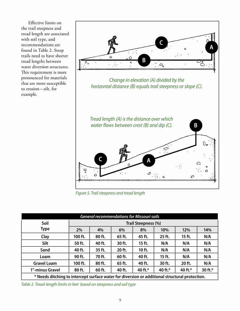
trail steepness (slope) and tread lengthTrail steepness or slope is the rate at which a trail rises or falls. it is determined by dividing the change
in elevation by the horizontal distance over which the elevation change takes place. steeper trails are more susceptible to erosion. Greater flow energy is associated with a steeper trail than with a less steep trail. steep trails allow water to travel at a higher velocity, making it easier for the water to pick up and transport soil particles.
Tread length is the length of trail over which water flows. The greater the tread length, the greater the distance over which erosion is possible. This is not to suggest that shorter trails should be used in order to limit erosion. it does indicate that water needs to be removed from a trail in order to limit the contact length. Trail steepness and tread length are shown in Figure 5.
bad
good
Figure 4. Topographic map showing good trail alignment following the contour and bad trail alignment traveling straight up and down the hills
9
Effective limits on the trail steepness and tread length are associated with soil type, and recommendations are found in Table 2. steep trails need to have shorter tread lengths between water diversion structures. This requirement is more pronounced for materials that are more susceptible to erosion—silt, for example.
General recommendations for Missouri soils
soiltype
trail steepness (%)2% 4% 6% 8% 10% 12% 14%
clay 100 ft. 80 ft. 65 ft. 45 ft. 25 ft. 15 ft. n/asilt 50 ft. 40 ft. 30 ft. 15 ft. n/a n/a n/a
sand 40 ft. 35 ft. 20 ft. 10 ft. n/a n/a n/aloam 90 ft. 70 ft. 60 ft. 40 ft. 15 ft. n/a n/a
Gravel loam 100 ft. 80 ft. 65 ft. 40 ft. 30 ft. 20 ft. n/a1”-minus Gravel 80 ft. 60 ft. 40 ft. 40 ft.* 40 ft.* 40 ft.* 30 ft.*
* needs ditching to intercept surface water for diversion or additional structural protection.
Table 2. Tread-length limits in feet based on steepness and soil type
a
b
Figure 5. Trail steepness and tread length
Change in elevation (A) divided by the horizontal distance (B) equals trail steepness or slope (C).
c
Tread length (A) is the distance over which water flows between crest (B) and dip (C).
ac
b
10
landscape locationThe landscape location determines how much water may impact the trail. Trails that are located higher
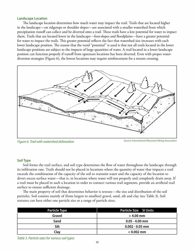
in the landscape—on ridgetops or shoulder slopes—are associated with a smaller watershed from which precipitation runoff can collect and be diverted onto a trail. These trails have a low potential for water to impact them. Trails that are located lower in the landscape—foot-slopes and floodplains—have a greater potential for water to impact the trails. This greater potential reflects the fact that watershed size increases with each lower landscape position. The reason that the word “potential” is used is that not all trails located in the lower landscape positions are subject to the impacts of large quantities of water. A trail located in a lower landscape position can function properly if runoff from upstream locations has been diverted. Even with proper water-diversion strategies (Figure 6), the lowest locations may require reinforcement for a stream crossing.
soil typesoil forms the trail surface, and soil type determines the flow of water throughout the landscape through
its infiltration rate. Trails should not be placed in locations where the quantity of water that impacts a trail exceeds the combination of the capacity of the soil to transmit water and the capacity of the location to divert excess surface water—that is, in locations where water will not properly and completely drain away. if a trail must be placed in such a location in order to connect various trail segments, provide an artificial trail surface to ensure sufficient drainage.
The main property of soil that determines behavior is texture—the size and distribution of the soil particles. soil consists mainly of (from largest to smallest) gravel, sand, silt and clay (see Table 3). soil textures can have either one particle size or a range of particle sizes.
Particle type Particle size sI UnitsGravel > 4.00 mmsand 0.05 - 4.00 mmsilt 0.002 - 0.05 mm
clay < 0.002 mm
Table 3. Particle sizes for various soil types
Figure 6. Trail with watershed delineation Source: International Mountain Biking Association
11
Wearing Resistance and erosion ResistanceThe behavioral properties of soil that are most important to trails are wearing resistance and erosion
resistance. Wearing resistance is the ability of soil to act as a wearing surface—that is, to resist the impact of use. Erosion resistance is the ability of a soil to resist erosion from the action of water. A soil with a high strength acts as a good wearing surface. The stronger the wearing surface, the longer the trail can last and resist disturbance from users. soil strength depends mainly upon texture, density and moisture content. Texture controls how water interacts with soil. Fine-grained soils, such as those containing clay and silt, often will hold water rather than allow it to drain away. Consequently, the soil is weakened and, with use, will create muddy conditions for riders. density—the mass of soil per volume—depends upon the compaction of the soil; greater compaction means greater strength. A lower moisture content (amount of water in soil) also means greater strength.
Erosion resistance refers to the ability of soil to resist displacement by water. soil’s erosion resistance is dependent on soil texture, specifically the parameters of interparticle cohesion and particle size. Water can loosen and carry soil particles through rainfall or sheet flow. Clayey soil has high cohesion between particles that makes it very resistant to erosion. Gravelly soil, with its very large particles that are heavy and difficult for water to transport, has high erosion resistance. silts and sands—which have little cohesion and small particle sizes—have low erosion resistance. Even without cohesion, gravelly soils have high erosion resistance because the large particle sizes require more and faster water to move the particles.
Clay soil, composed of very small particles, is weak when wet and stays wet for extended periods. The extended period of wetness is due to the attraction between clay particles and water. Water molecules are attracted to the clay particles and are difficult to remove. Because the particles are so small, it is also difficult for water to move through the soil. Even though clay is weak and has low wearing resistance, it has high erosion resistance because of its cohesion.
Silty soil does not have the chemical attraction for water that clays have, but water still percolates through it slowly due to the small particle size. The presence of excess water results in low wearing resistance, and its small particle size—with no clay content to provide cohesion—gives it low erosion resistance.
Loam—a mixture of clays, silts and sands—has moderate erosion resistance because of the cohesive clay particles binding the silts and sands together. loamy soil also has moderate trampling resistance because of the strength from compaction and moisture content. Muddiness may become a problem in very wet conditions.
Sands—which are stronger than clays, silt and loams—allow water to infiltrate or percolate quickly and are not weakened by water. On the other hand, they are highly erosive due to the small particle size and lack of cohesion.
Gravels are strong and resistant to trampling. They offer high erosion resistance due to the large particle sizes. Water moves through these soils quickly.
Restrictive layers At any given location, various subsurface soil layers, or horizons, will have different textures. The
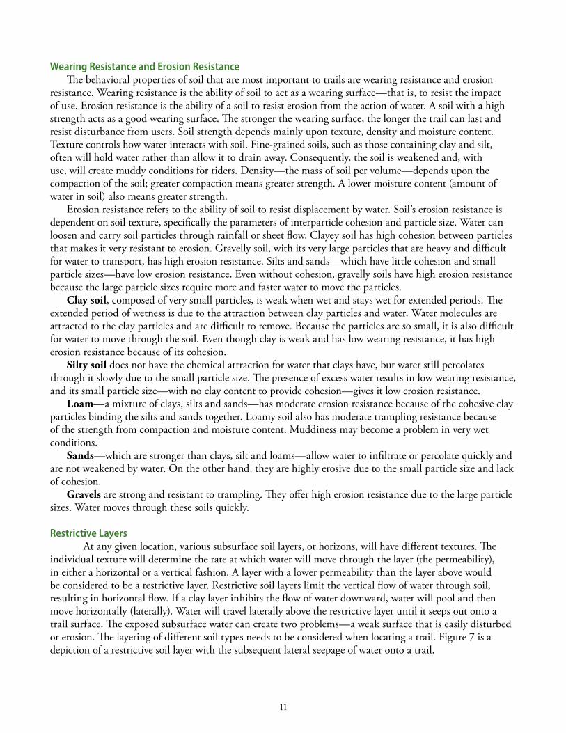
individual texture will determine the rate at which water will move through the layer (the permeability), in either a horizontal or a vertical fashion. A layer with a lower permeability than the layer above would be considered to be a restrictive layer. Restrictive soil layers limit the vertical flow of water through soil, resulting in horizontal flow. if a clay layer inhibits the flow of water downward, water will pool and then move horizontally (laterally). Water will travel laterally above the restrictive layer until it seeps out onto a trail surface. The exposed subsurface water can create two problems—a weak surface that is easily disturbed or erosion. The layering of different soil types needs to be considered when locating a trail. Figure 7 is a depiction of a restrictive soil layer with the subsequent lateral seepage of water onto a trail.
12
b. WateR-DIVeRsIon stRUctURes anD tRaIl-sURface sHaPe: ReMoVInG WateR fRoM tRaIls
Once a trail has been designed to minimize water flow onto it, the next thing to consider is how to remove water that does make its way there. This is accomplished by shaping the trail surface and using water-diversion structures to force water off the trail.
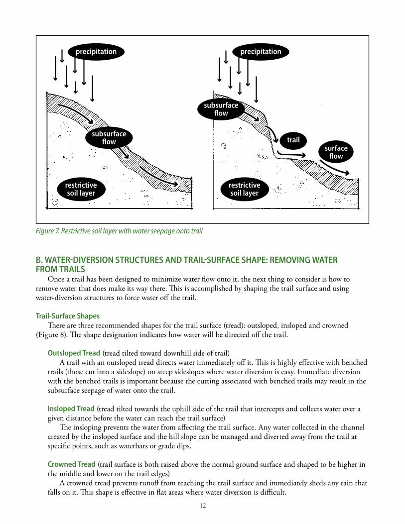
trail-surface shapesThere are three recommended shapes for the trail surface (tread): outsloped, insloped and crowned
(Figure 8). The shape designation indicates how water will be directed off the trail.
outsloped tread (tread tilted toward downhill side of trail)A trail with an outsloped tread directs water immediately off it. This is highly effective with benched
trails (those cut into a sideslope) on steep sideslopes where water diversion is easy. immediate diversion with the benched trails is important because the cutting associated with benched trails may result in the subsurface seepage of water onto the trail.
Insloped tread (tread tilted towards the uphill side of the trail that intercepts and collects water over a given distance before the water can reach the trail surface)
The insloping prevents the water from affecting the trail surface. Any water collected in the channel created by the insloped surface and the hill slope can be managed and diverted away from the trail at specific points, such as waterbars or grade dips.
crowned tread (trail surface is both raised above the normal ground surface and shaped to be higher in the middle and lower on the trail edges)
A crowned tread prevents runoff from reaching the trail surface and immediately sheds any rain that falls on it. This shape is effective in flat areas where water diversion is difficult.
Figure 7. Restrictive soil layer with water seepage onto trail
precipitation
restrictive soil layer
subsurfaceflow
subsurfaceflow
precipitation
restrictive soil layer
surfaceflow
trail
13
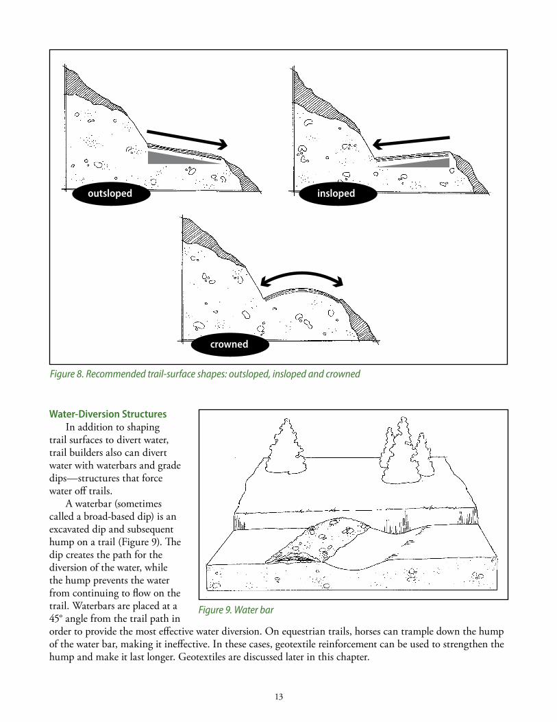
Water-Diversion structuresin addition to shaping
trail surfaces to divert water, trail builders also can divert water with waterbars and grade dips—structures that force water off trails.
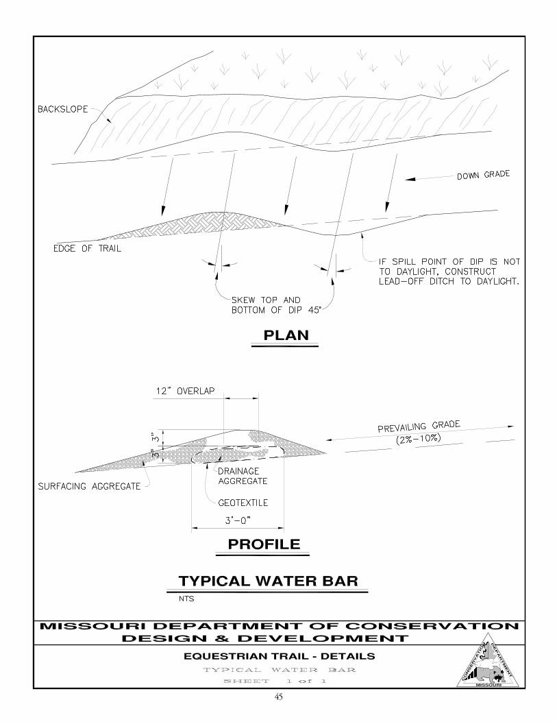
A waterbar (sometimes called a broad-based dip) is an excavated dip and subsequent hump on a trail (Figure 9). The dip creates the path for the diversion of the water, while the hump prevents the water from continuing to flow on the trail. Waterbars are placed at a 45° angle from the trail path in order to provide the most effective water diversion. On equestrian trails, horses can trample down the hump of the water bar, making it ineffective. in these cases, geotextile reinforcement can be used to strengthen the hump and make it last longer. Geotextiles are discussed later in this chapter.
outsloped
crowned
insloped
Figure 8. Recommended trail-surface shapes: outsloped, insloped and crowned
Figure 9. Water bar
14
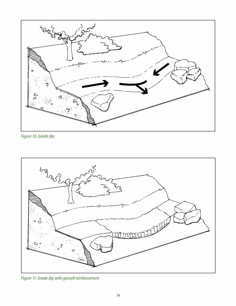
Figure 10. Grade dip
Figure 11. Grade dip with geocell reinforcement
15
A grade dip (also called a grade reversal) is used to divert water from a contour trail (Figure 10). Built with this method, a trail path has a portion with a greater steepness than the natural slope, followed by a portion with a slope in the opposite direction. in other words, the trail path goes downhill and then uphill. Grade dips are particularly useful for trails that follow a contour line on a very small slope. They also can be effective in crossing concave areas. in concave areas, where soils can be weak when wet, grade dips can be combined with geocells to increase surface strength (Figure 11).
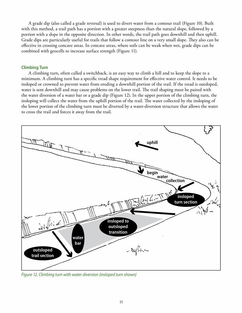
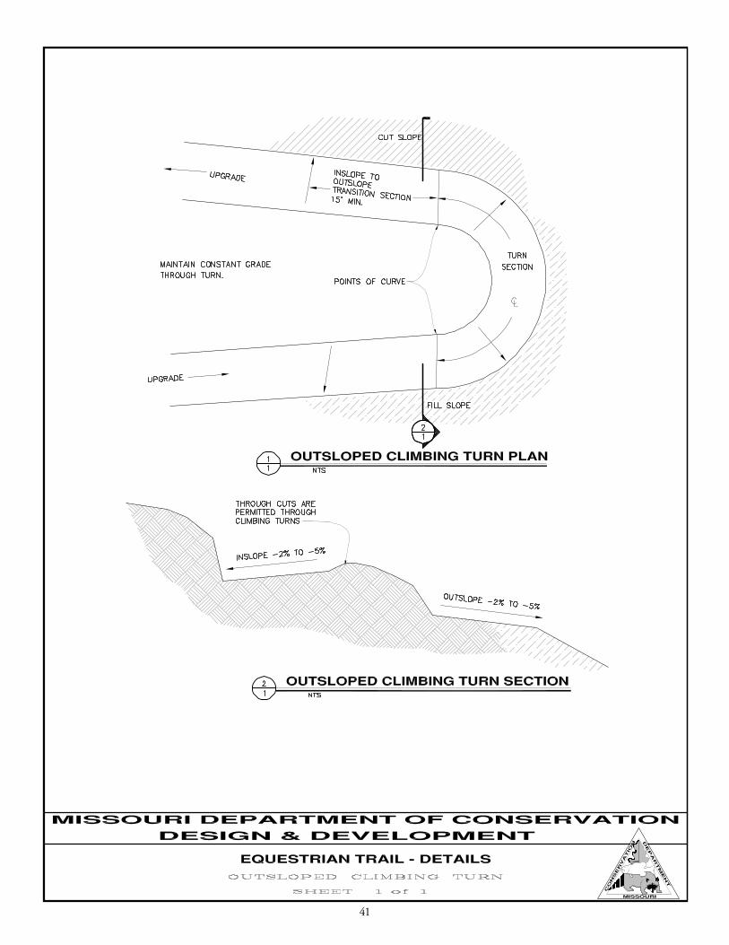
climbing turn A climbing turn, often called a switchback, is an easy way to climb a hill and to keep the slope to a
minimum. A climbing turn has a specific tread shape requirement for effective water control. it needs to be insloped or crowned to prevent water from eroding a downhill portion of the trail. if the tread is outsloped, water is sent downhill and may cause problems on the lower trail. The trail shaping must be paired with the water diversion of a water bar or a grade dip (Figure 12). in the upper portion of the climbing turn, the insloping will collect the water from the uphill portion of the trail. The water collected by the insloping of the lower portion of the climbing turn must be diverted by a water-diversion structure that allows the water to cross the trail and forces it away from the trail.
Figure 12. Climbing turn with water diversion (insloped turn shown)
inslopedturn section
outslopedtrail section
insloped tooutslopedtransition
waterbar
begin water collection
uphill
16
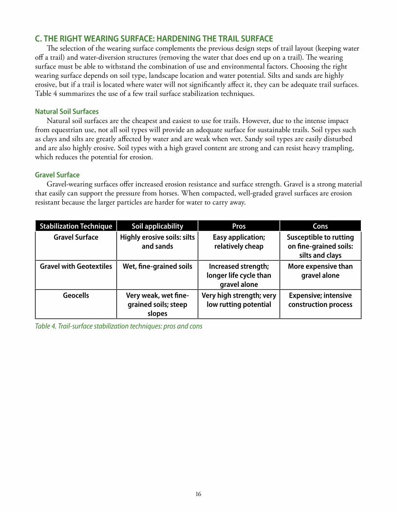
c. tHe RIGHt WeaRInG sURface: HaRDenInG tHe tRaIl sURface The selection of the wearing surface complements the previous design steps of trail layout (keeping water
off a trail) and water-diversion structures (removing the water that does end up on a trail). The wearing surface must be able to withstand the combination of use and environmental factors. Choosing the right wearing surface depends on soil type, landscape location and water potential. silts and sands are highly erosive, but if a trail is located where water will not significantly affect it, they can be adequate trail surfaces. Table 4 summarizes the use of a few trail surface stabilization techniques.
natural soil surfacesnatural soil surfaces are the cheapest and easiest to use for trails. However, due to the intense impact
from equestrian use, not all soil types will provide an adequate surface for sustainable trails. soil types such as clays and silts are greatly affected by water and are weak when wet. sandy soil types are easily disturbed and are also highly erosive. soil types with a high gravel content are strong and can resist heavy trampling, which reduces the potential for erosion.
Gravel surfaceGravel-wearing surfaces offer increased erosion resistance and surface strength. Gravel is a strong material
that easily can support the pressure from horses. When compacted, well-graded gravel surfaces are erosion resistant because the larger particles are harder for water to carry away.
stabilization technique soil applicability Pros consGravel surface Highly erosive soils: silts
and sandseasy application; relatively cheap
susceptible to rutting on fine-grained soils:
silts and claysGravel with Geotextiles Wet, fine-grained soils Increased strength;
longer life cycle than gravel alone
More expensive than gravel alone
Geocells Very weak, wet fine-grained soils; steep
slopes
Very high strength; very low rutting potential
expensive; intensive construction process
Table 4. Trail-surface stabilization techniques: pros and cons
17
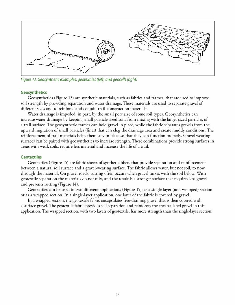
Geosynthetics Geosynthetics (Figure 13) are synthetic materials, such as fabrics and frames, that are used to improve
soil strength by providing separation and water drainage. These materials are used to separate gravel of different sizes and to reinforce and contain trail-construction materials.
Water drainage is impeded, in part, by the small pore size of some soil types. Geosynthetics can increase water drainage by keeping small particle sized soils from mixing with the larger sized particles of a trail surface. The geosynthetic frames can hold gravel in place, while the fabric separates gravels from the upward migration of small particles (fines) that can clog the drainage area and create muddy conditions. The reinforcement of trail materials helps them stay in place so that they can function properly. Gravel-wearing surfaces can be paired with geosynthetics to increase strength. These combinations provide strong surfaces in areas with weak soils, require less material and increase the life of a trail.
GeotextilesGeotextiles (Figure 15) are fabric sheets of synthetic fibers that provide separation and reinforcement
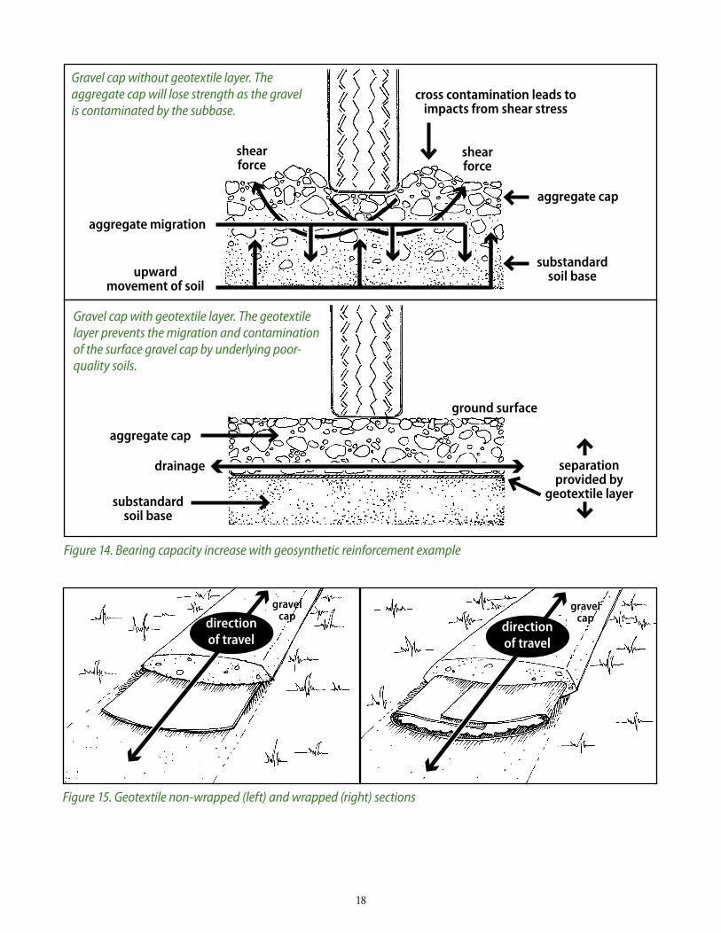
between a natural soil surface and a gravel-wearing surface. The fabric allows water, but not soil, to flow through the material. On gravel roads, rutting often occurs when gravel mixes with the soil below. With geotextile separation the materials do not mix, and the result is a stronger surface that requires less gravel and prevents rutting (Figure 14).
Geotextiles can be used in two different applications (Figure 15): as a single-layer (non-wrapped) section or as a wrapped section. in a single-layer application, one layer of the fabric is covered by gravel.
in a wrapped section, the geotextile fabric encapsulates free-draining gravel that is then covered with a surface gravel. The geotextile fabric provides soil separation and reinforces the encapsulated gravel in this application. The wrapped section, with two layers of geotextile, has more strength than the single-layer section.
Figure 13. Geosynthetic examples: geotextiles (left) and geocells (right)
18
Figure 15. Geotextile non-wrapped (left) and wrapped (right) sections
directionof travel
directionof travel
Figure 14. Bearing capacity increase with geosynthetic reinforcement example
cross contamination leads to impacts from shear stress
Gravel cap without geotextile layer. The aggregate cap will lose strength as the gravelis contaminated by the subbase.
Gravel cap with geotextile layer. The geotextile layer prevents the migration and contamination of the surface gravel cap by underlying poor-quality soils.
drainage
substandardsoil base
substandardsoil base
aggregate cap
aggregate cap
shearforce
shearforce
separation provided by
geotextile layer
ground surface
aggregate migration
upward movement of soil
gravel cap
gravel cap
19
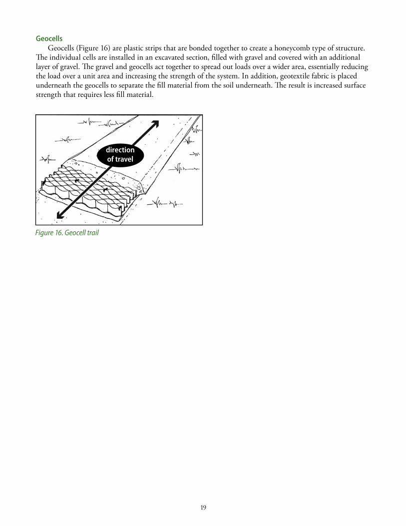
Figure 16. Geocell trail
Geocells Geocells (Figure 16) are plastic strips that are bonded together to create a honeycomb type of structure.
The individual cells are installed in an excavated section, filled with gravel and covered with an additional layer of gravel. The gravel and geocells act together to spread out loads over a wider area, essentially reducing the load over a unit area and increasing the strength of the system. in addition, geotextile fabric is placed underneath the geocells to separate the fill material from the soil underneath. The result is increased surface strength that requires less fill material.
gravel cap
directionof travel
20
cHaP teR 3 fIxInG aban D o n eD tR aIl s
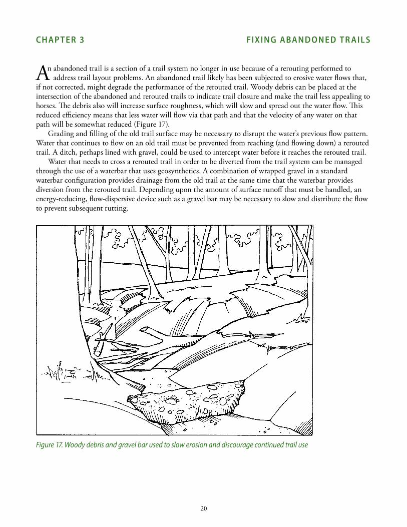
An abandoned trail is a section of a trail system no longer in use because of a rerouting performed to address trail layout problems. An abandoned trail likely has been subjected to erosive water flows that,
if not corrected, might degrade the performance of the rerouted trail. Woody debris can be placed at the intersection of the abandoned and rerouted trails to indicate trail closure and make the trail less appealing to horses. The debris also will increase surface roughness, which will slow and spread out the water flow. This reduced efficiency means that less water will flow via that path and that the velocity of any water on that path will be somewhat reduced (Figure 17).
Grading and filling of the old trail surface may be necessary to disrupt the water’s previous flow pattern. Water that continues to flow on an old trail must be prevented from reaching (and flowing down) a rerouted trail. A ditch, perhaps lined with gravel, could be used to intercept water before it reaches the rerouted trail.
Water that needs to cross a rerouted trail in order to be diverted from the trail system can be managed through the use of a waterbar that uses geosynthetics. A combination of wrapped gravel in a standard waterbar configuration provides drainage from the old trail at the same time that the waterbar provides diversion from the rerouted trail. depending upon the amount of surface runoff that must be handled, an energy-reducing, flow-dispersive device such as a gravel bar may be necessary to slow and distribute the flow to prevent subsequent rutting.
Figure 17. Woody debris and gravel bar used to slow erosion and discourage continued trail use
21
cHaP teR 4 D e sI G n PRo ceDUR e s
Erosion problems on equestrian trails can be solved by rerouting existing trails or hardening the existing trail surface. To understand the source of the erosion problem and what needs to be done, you must understand
the natural conditions (location in the landscape and soil type), trail characteristics (trail-alignment angle, steepness and length) and extent of erosion (minor versus major rutting) of the trail. The extent of erosion will indicate whether major steps (such as rerouting) or minor steps (such as surface hardening) are warranted.
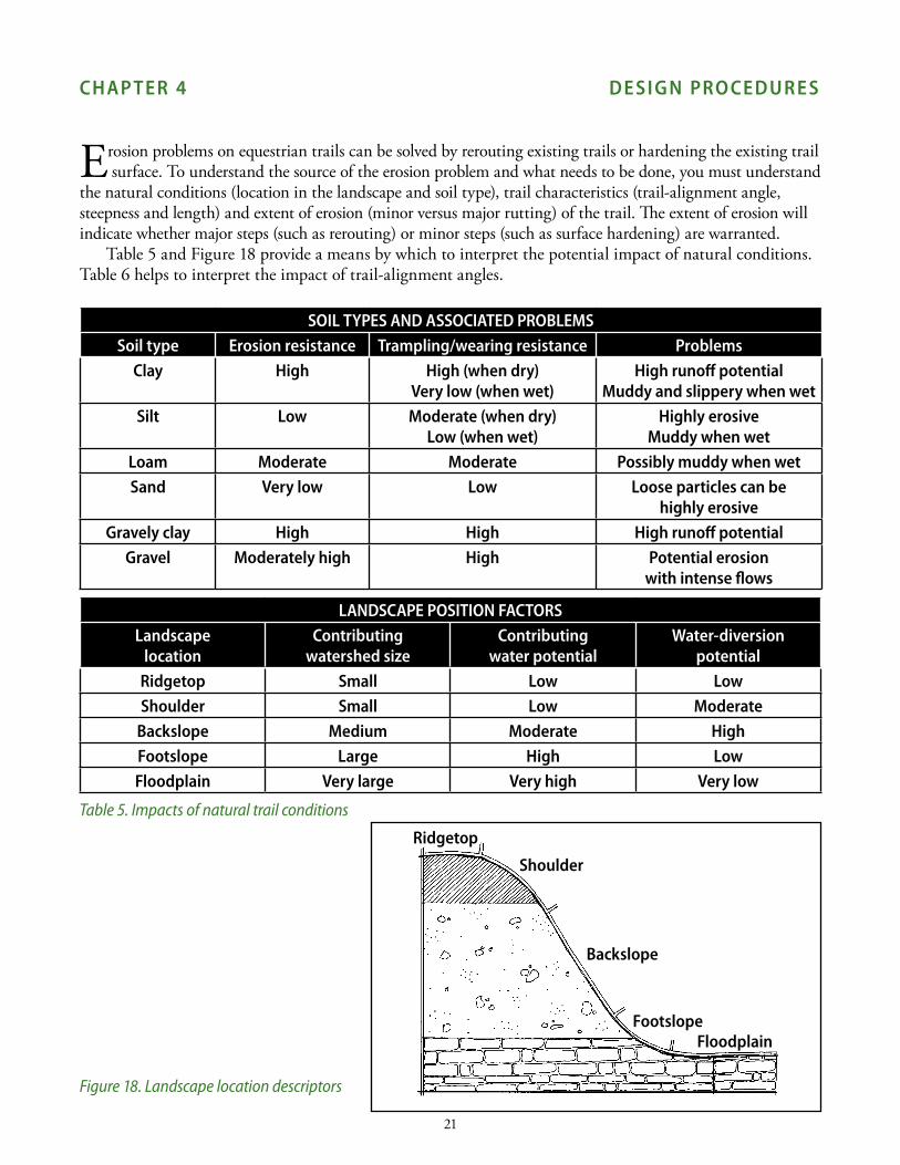
Table 5 and Figure 18 provide a means by which to interpret the potential impact of natural conditions. Table 6 helps to interpret the impact of trail-alignment angles.
soIl tYPes anD assocIateD PRobleMssoil type erosion resistance trampling/wearing resistance Problems
clay High High (when dry)Very low (when wet)
High runoff potentialMuddy and slippery when wet
silt low Moderate (when dry)low (when wet)
Highly erosiveMuddy when wet
loam Moderate Moderate Possibly muddy when wetsand Very low low loose particles can be
highly erosiveGravely clay High High High runoff potential
Gravel Moderately high High Potential erosion with intense flows
lanDscaPe PosItIon factoRslandscape
locationcontributing
watershed sizecontributing
water potentialWater-diversion
potentialRidgetop small low lowshoulder small low Moderate
backslope Medium Moderate Highfootslope large High lowfloodplain Very large Very high Very low
Table 5. Impacts of natural trail conditions
Figure 18. Landscape location descriptors
Ridgetop
shoulder
backslope
footslopefloodplain
No
Reference Figure 21 for surface selection
No
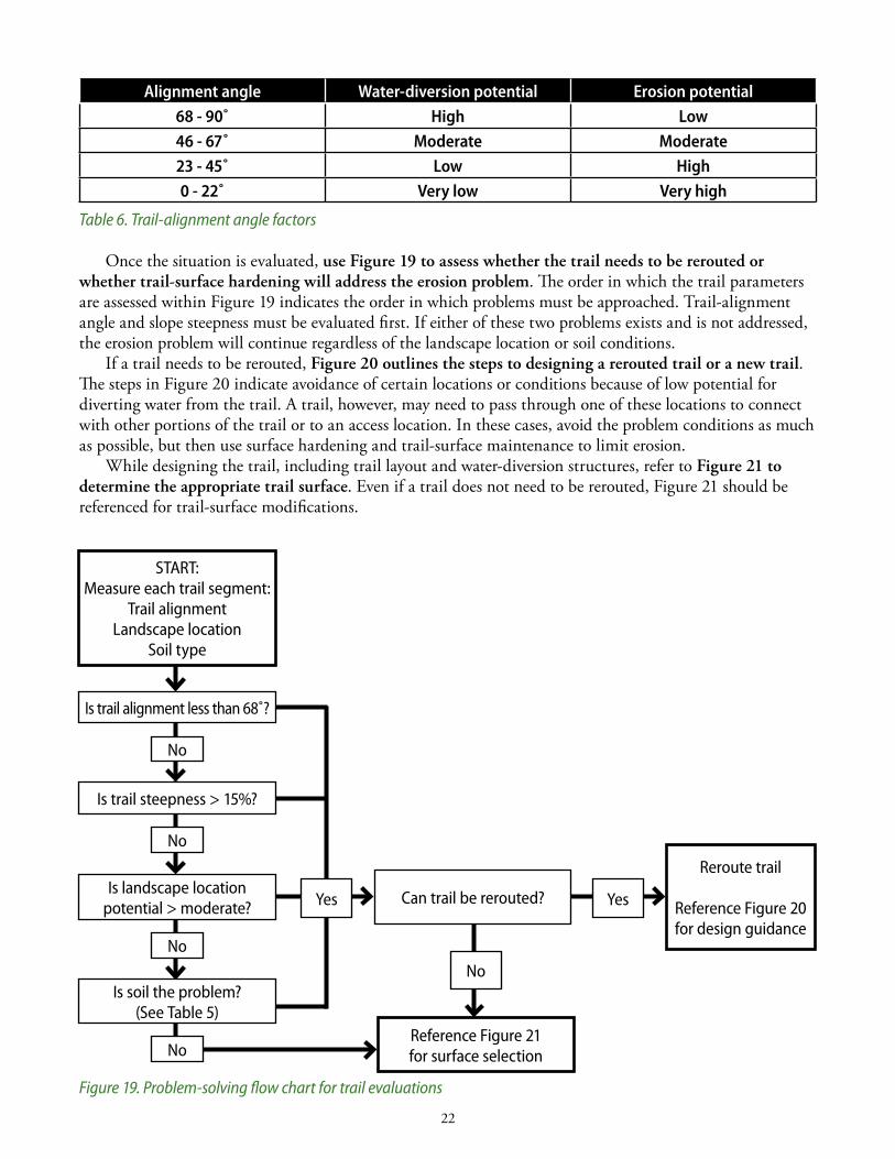
alignment angle Water-diversion potential erosion potential68 - 90˚ High low46 - 67˚ Moderate Moderate23 - 45˚ low High0 - 22˚ Very low Very high
Table 6. Trail-alignment angle factors
Once the situation is evaluated, use Figure 19 to assess whether the trail needs to be rerouted or whether trail-surface hardening will address the erosion problem. The order in which the trail parameters are assessed within Figure 19 indicates the order in which problems must be approached. Trail-alignment angle and slope steepness must be evaluated first. if either of these two problems exists and is not addressed, the erosion problem will continue regardless of the landscape location or soil conditions.
if a trail needs to be rerouted, Figure 20 outlines the steps to designing a rerouted trail or a new trail. The steps in Figure 20 indicate avoidance of certain locations or conditions because of low potential for diverting water from the trail. A trail, however, may need to pass through one of these locations to connect with other portions of the trail or to an access location. in these cases, avoid the problem conditions as much as possible, but then use surface hardening and trail-surface maintenance to limit erosion.
While designing the trail, including trail layout and water-diversion structures, refer to Figure 21 to determine the appropriate trail surface. Even if a trail does not need to be rerouted, Figure 21 should be referenced for trail-surface modifications.
Figure 19. Problem-solving flow chart for trail evaluations
START:Measure each trail segment:
Trail alignmentLandscape location
Soil type
Is trail alignment less than 68˚?
Is landscape location potential > moderate?
Is soil the problem?(See Table 5)
No
No
No
Yes Can trail be rerouted? Yes
Reroute trail
Reference Figure 20 for design guidance
22 23
Is trail steepness > 15%?
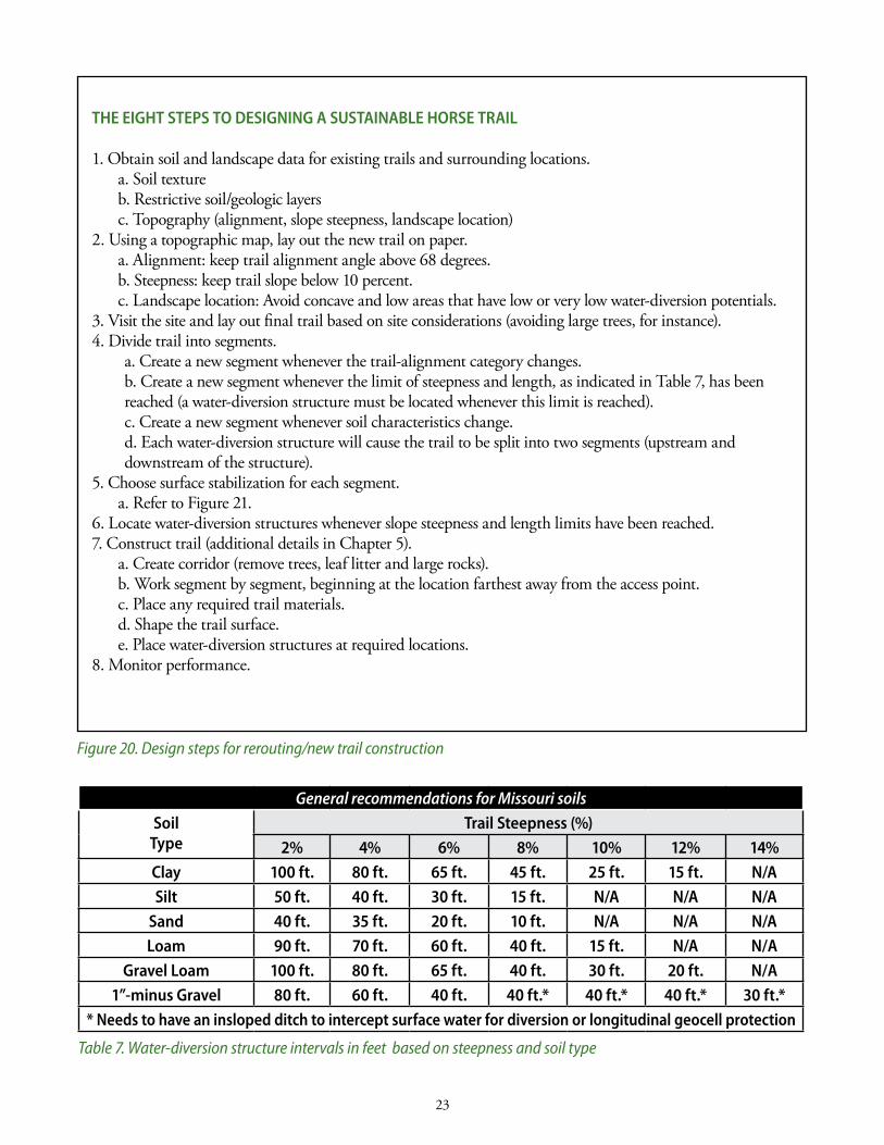
tHe eIGHt stePs to DesIGnInG a sUstaInable HoRse tRaIl
1. Obtain soil and landscape data for existing trails and surrounding locations.a. soil textureb. Restrictive soil/geologic layersc. Topography (alignment, slope steepness, landscape location)
2. using a topographic map, lay out the new trail on paper.a. Alignment: keep trail alignment angle above 68 degrees.b. steepness: keep trail slope below 10 percent.c. landscape location: Avoid concave and low areas that have low or very low water-diversion potentials.
3. Visit the site and lay out final trail based on site considerations (avoiding large trees, for instance).4. divide trail into segments.
a. Create a new segment whenever the trail-alignment category changes.b. Create a new segment whenever the limit of steepness and length, as indicated in Table 7, has been reached (a water-diversion structure must be located whenever this limit is reached). c. Create a new segment whenever soil characteristics change. d. Each water-diversion structure will cause the trail to be split into two segments (upstream and downstream of the structure).
5. Choose surface stabilization for each segment.a. Refer to Figure 21.
6. locate water-diversion structures whenever slope steepness and length limits have been reached. 7. Construct trail (additional details in Chapter 5).
a. Create corridor (remove trees, leaf litter and large rocks). b. Work segment by segment, beginning at the location farthest away from the access point.c. Place any required trail materials.d. shape the trail surface.e. Place water-diversion structures at required locations.
8. Monitor performance.
Figure 20. Design steps for rerouting/new trail construction
23
General recommendations for Missouri soils
soiltype
trail steepness (%)2% 4% 6% 8% 10% 12% 14%
clay 100 ft. 80 ft. 65 ft. 45 ft. 25 ft. 15 ft. n/asilt 50 ft. 40 ft. 30 ft. 15 ft. n/a n/a n/a
sand 40 ft. 35 ft. 20 ft. 10 ft. n/a n/a n/aloam 90 ft. 70 ft. 60 ft. 40 ft. 15 ft. n/a n/a
Gravel loam 100 ft. 80 ft. 65 ft. 40 ft. 30 ft. 20 ft. n/a1”-minus Gravel 80 ft. 60 ft. 40 ft. 40 ft.* 40 ft.* 40 ft.* 30 ft.*
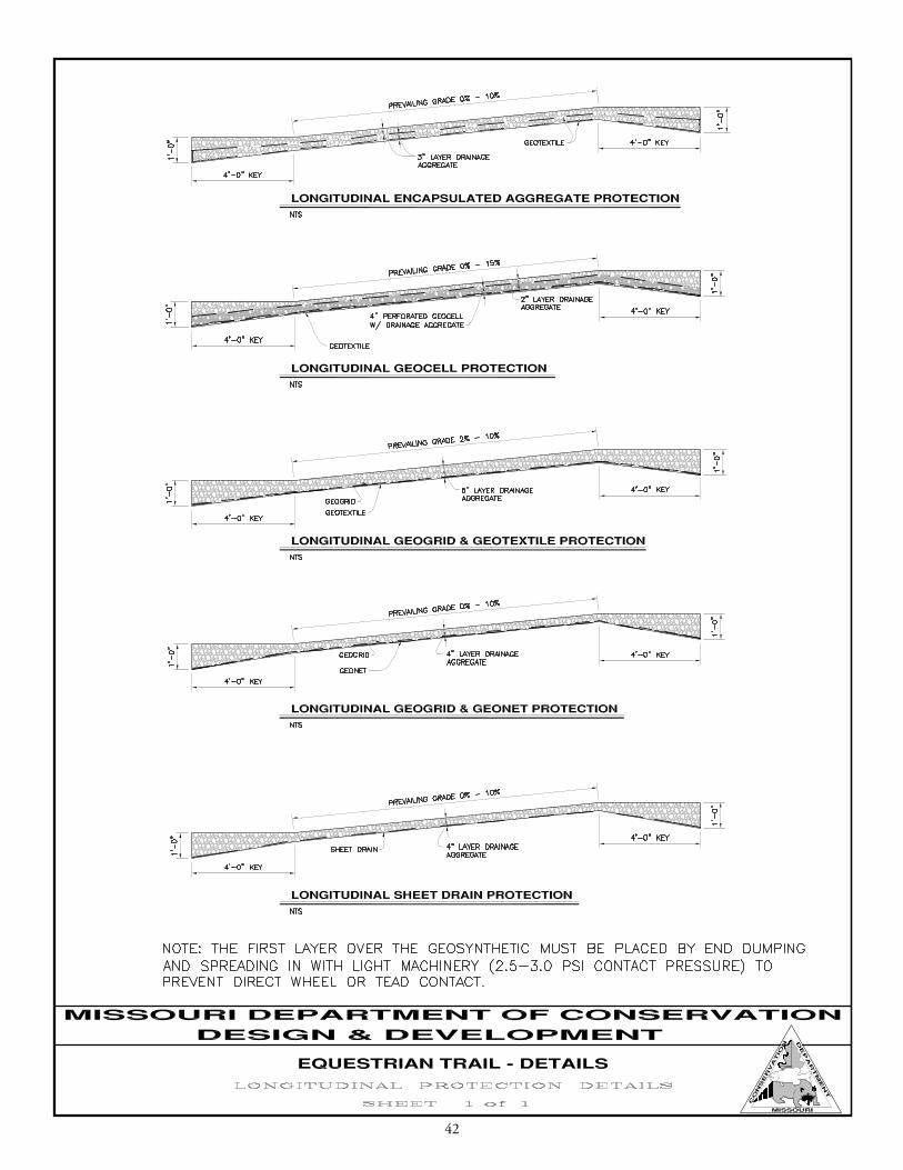
* needs to have an insloped ditch to intercept surface water for diversion or longitudinal geocell protection
Table 7. Water-diversion structure intervals in feet based on steepness and soil type

Figure 21 helps to select appropriate surface treatments. Establish a treatment for each trail segment based on the natural conditions and trail characteristics. The procedure for using Figure 21 is as follows:
First, select the proper trail alignment angle and steepness category from the left side of the figure. note that there are no steepness categories above 25 percent because they are generally not sustainable. This selection will limit your search to five rows of boxes.
now select the applicable soil type from the right side of the figure. This will limit your choices to one row of boxes.
With this row selected, you have only three choices based on the water potential on that segment of trail. under the correct water-potential heading, find the box with an “x” and follow that column to the bottom of the figure. There you find the appropriate surface treatment for that particular trail segment.
Figure 21. Trail surface selection chart—see opposite page 4
trail-design procedures checklist
_______ Collect trail information:Trail soil texture dataRestrictive soil/geologic layer informationTopographic map
_______ determine trail parameters (for each segment).Trail alignment (degrees)slope steepness (percentage)landscape position information
_______ Follow the problem-solving flow chart (Figure 19).
_______ Follow the design steps in Figure 20 (including the location and design of water-control structures).
_______ select the best trail surface from Figure 21.
_______ Establish a trail-monitoring schedule.
24 25

Water Potential
Low Medium High
69%to
90%
0%to
7%
X X X Silt/Sand
X X X Loam
X X X Clay
X X X Gravel Loam
X X X Gravelly Clay
8%to
15%
X X X Silt/Sand
X X X Loam
X X X Clay
X X X Gravel Loam
X X X Gravelly Clay
16%to
25%
X X X Silt/Sand
X X X Loam
X X X Clay
X X X Gravel Loam
X X X Gravelly Clay
23%to
68%
0%to
7%
X X X Silt/Sand
X X X Loam
X X X Clay
X X X Gravel Loam
X X X Gravelly Clay
8%to
15%
X X X Silt/Sand
X X X Loam
X X X Clay
X X X Gravel Loam
X X X Gravelly Clay
16%to
25%
X X X Silt/Sand
X X X Loam
X X X Clay
X X X Gravel Loam
X X X Gravelly Clay
0%to
22%
0%to
7%
X X X Silt/Sand
X X X Loam
X X X Clay
X X X Gravel Loam
X X X Gravelly Clay
8%to
15%
X X X Silt/Sand
X X X Loam
X X X Clay
X X X Gravel Loam
X X X Gravelly Clay
16%to
25%
X X X Silt/Sand
X X X Loam
X X X Clay
X X X Gravel Loam
X X X Gravelly Clay
None Gravel GT GC None Gravel GT GC None Gravel GT GC
solutions
trai
l alig
nmen
t
soil
type
trai
l ste
epne
sstr
ail s
teep
ness
trai
l ste
epne
ss
none - surface stabilization not required, but needs ongoing maintenanceGravel - add at least 4 inches of surface aggregate
Gt - Gravel with geotextile (wrapped or non-wrapped, depending upon the situation)Gc - 4-inch geocells (use 8-inch for stream crossings)
25
26 27
cHaP teR 5 co ns tRUc tI o n PRo ceDUR e s
specifications for rocksurface aggregate: 1-inch minus base largest particle size: 1 inch Well-graded with fines Fines (<#200 sieve) should not be greater than 30 percent by weight.
drainage Aggregate: 1-inch clean aggregate – no fines
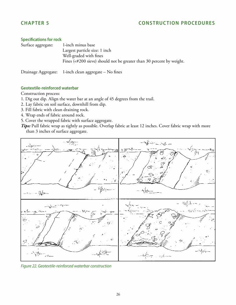
Geotextile-reinforced waterbarConstruction process:1. dig out dip. Align the water bar at an angle of 45 degrees from the trail.2. lay fabric on soil surface, downhill from dip. 3. Fill fabric with clean draining rock.4. Wrap ends of fabric around rock.5. Cover the wrapped fabric with surface aggregate.Tips: Pull fabric wrap as tightly as possible. Overlap fabric at least 12 inches. Cover fabric wrap with more
than 3 inches of surface aggregate.
Figure 22. Geotextile-reinforced waterbar construction
27
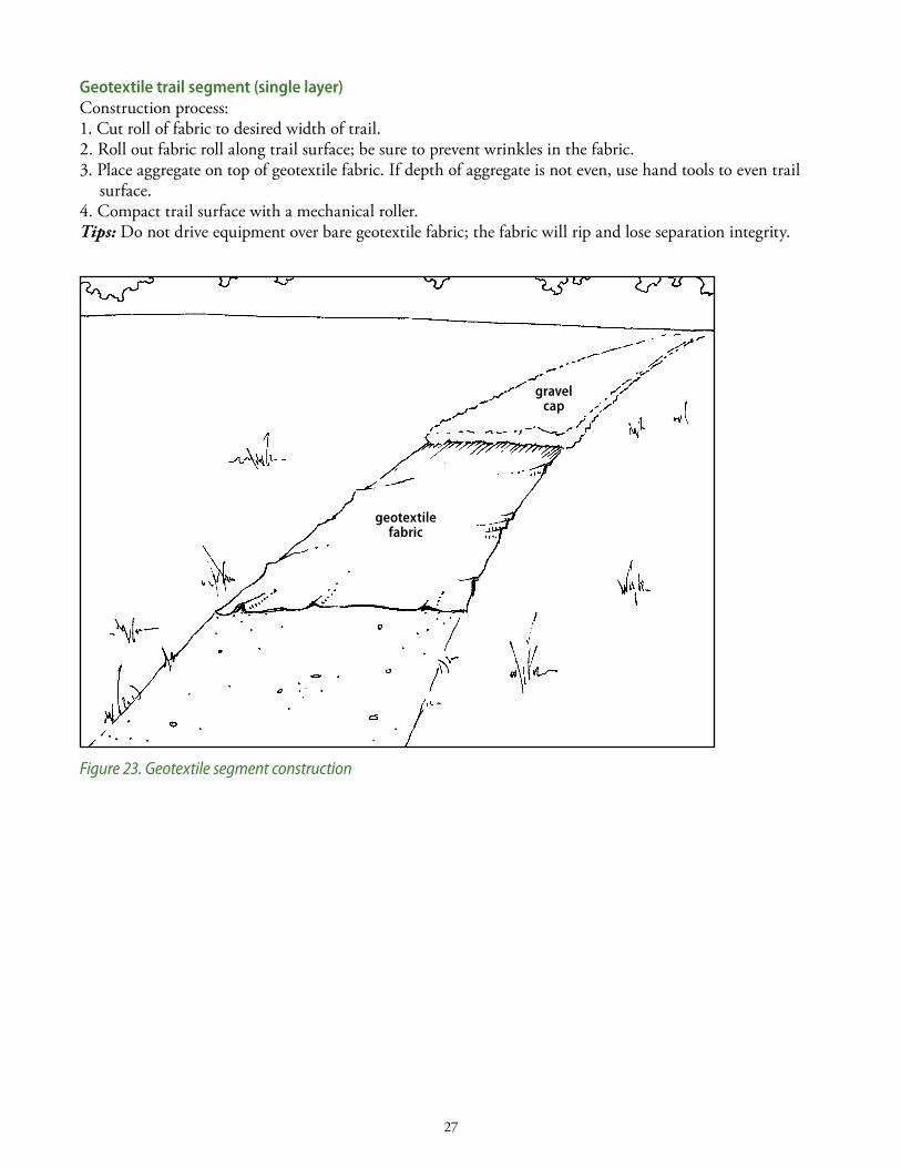
Geotextile trail segment (single layer)Construction process:1. Cut roll of fabric to desired width of trail.2. Roll out fabric roll along trail surface; be sure to prevent wrinkles in the fabric.3. Place aggregate on top of geotextile fabric. if depth of aggregate is not even, use hand tools to even trail
surface.4. Compact trail surface with a mechanical roller.Tips: do not drive equipment over bare geotextile fabric; the fabric will rip and lose separation integrity.
Figure 23. Geotextile segment construction
gravel cap
geotextilefabric
28 29
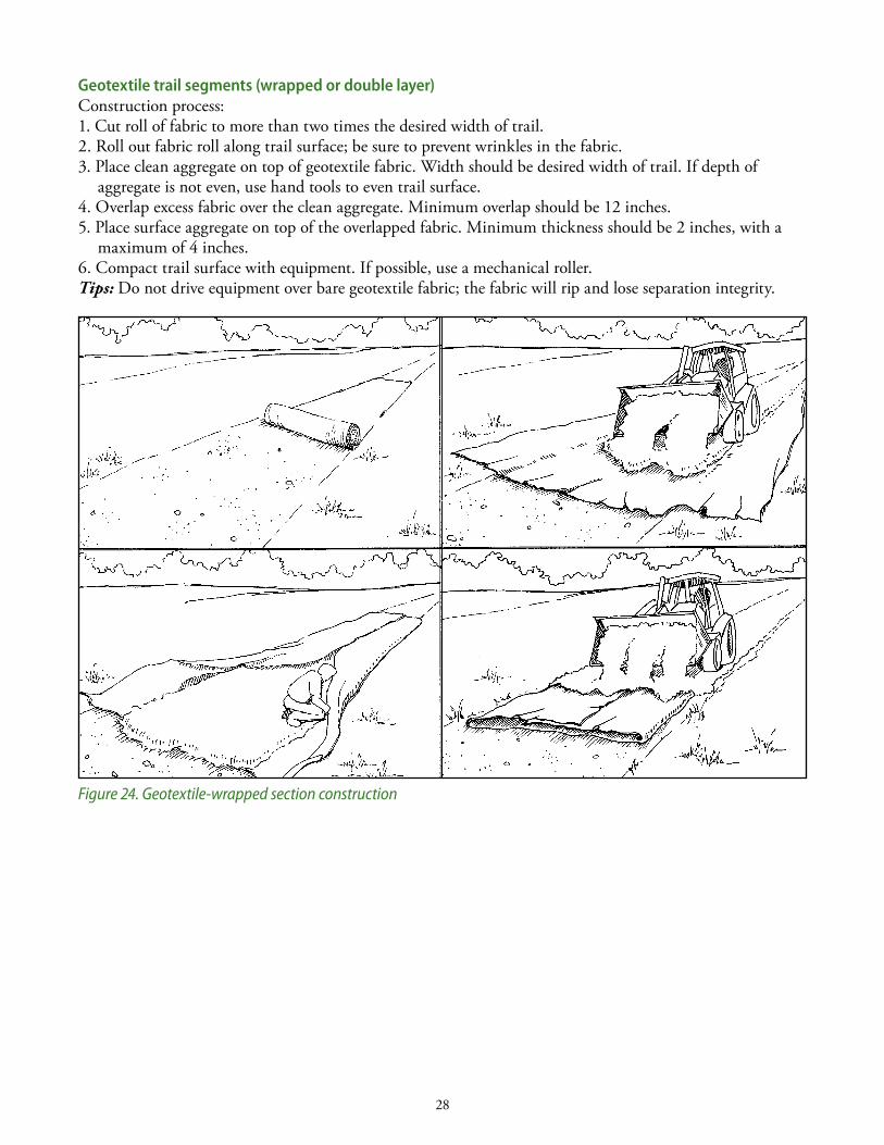
Geotextile trail segments (wrapped or double layer)Construction process:1. Cut roll of fabric to more than two times the desired width of trail.2. Roll out fabric roll along trail surface; be sure to prevent wrinkles in the fabric.3. Place clean aggregate on top of geotextile fabric. Width should be desired width of trail. if depth of
aggregate is not even, use hand tools to even trail surface. 4. Overlap excess fabric over the clean aggregate. Minimum overlap should be 12 inches.5. Place surface aggregate on top of the overlapped fabric. Minimum thickness should be 2 inches, with a
maximum of 4 inches.6. Compact trail surface with equipment. if possible, use a mechanical roller.Tips: do not drive equipment over bare geotextile fabric; the fabric will rip and lose separation integrity.
Figure 24. Geotextile-wrapped section construction
29
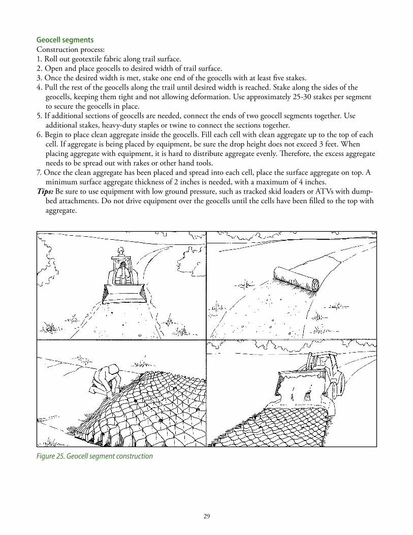
Geocell segmentsConstruction process:1. Roll out geotextile fabric along trail surface.2. Open and place geocells to desired width of trail surface.3. Once the desired width is met, stake one end of the geocells with at least five stakes.4. Pull the rest of the geocells along the trail until desired width is reached. stake along the sides of the
geocells, keeping them tight and not allowing deformation. use approximately 25-30 stakes per segment to secure the geocells in place.
5. if additional sections of geocells are needed, connect the ends of two geocell segments together. use additional stakes, heavy-duty staples or twine to connect the sections together.
6. Begin to place clean aggregate inside the geocells. Fill each cell with clean aggregate up to the top of each cell. if aggregate is being placed by equipment, be sure the drop height does not exceed 3 feet. When placing aggregate with equipment, it is hard to distribute aggregate evenly. Therefore, the excess aggregate needs to be spread out with rakes or other hand tools.
7. Once the clean aggregate has been placed and spread into each cell, place the surface aggregate on top. A minimum surface aggregate thickness of 2 inches is needed, with a maximum of 4 inches.
Tips: Be sure to use equipment with low ground pressure, such as tracked skid loaders or ATVs with dump-bed attachments. do not drive equipment over the geocells until the cells have been filled to the top with aggregate.
Figure 25. Geocell segment construction
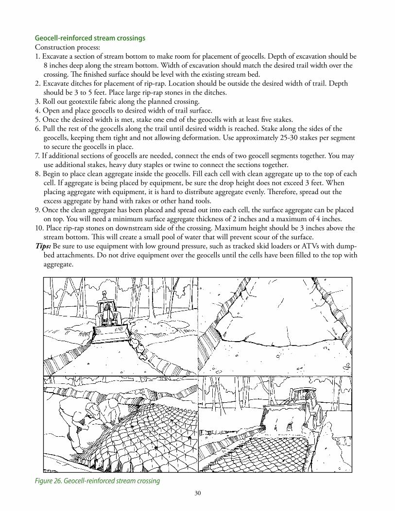
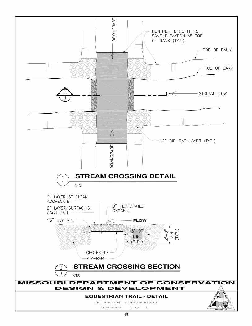
Geocell-reinforced stream crossingsConstruction process:1. Excavate a section of stream bottom to make room for placement of geocells. depth of excavation should be
8 inches deep along the stream bottom. Width of excavation should match the desired trail width over the crossing. The finished surface should be level with the existing stream bed.
2. Excavate ditches for placement of rip-rap. location should be outside the desired width of trail. depth should be 3 to 5 feet. Place large rip-rap stones in the ditches.
3. Roll out geotextile fabric along the planned crossing. 4. Open and place geocells to desired width of trail surface.5. Once the desired width is met, stake one end of the geocells with at least five stakes.6. Pull the rest of the geocells along the trail until desired width is reached. stake along the sides of the
geocells, keeping them tight and not allowing deformation. use approximately 25-30 stakes per segment to secure the geocells in place.
7. if additional sections of geocells are needed, connect the ends of two geocell segments together. You may use additional stakes, heavy duty staples or twine to connect the sections together.
8. Begin to place clean aggregate inside the geocells. Fill each cell with clean aggregate up to the top of each cell. if aggregate is being placed by equipment, be sure the drop height does not exceed 3 feet. When placing aggregate with equipment, it is hard to distribute aggregate evenly. Therefore, spread out the excess aggregate by hand with rakes or other hand tools.
9. Once the clean aggregate has been placed and spread out into each cell, the surface aggregate can be placed on top. You will need a minimum surface aggregate thickness of 2 inches and a maximum of 4 inches.
10. Place rip-rap stones on downstream side of the crossing. Maximum height should be 3 inches above the stream bottom. This will create a small pool of water that will prevent scour of the surface.
Tips: Be sure to use equipment with low ground pressure, such as tracked skid loaders or ATVs with dump-bed attachments. do not drive equipment over the geocells until the cells have been filled to the top with aggregate.
Figure 26. Geocell-reinforced stream crossing
30
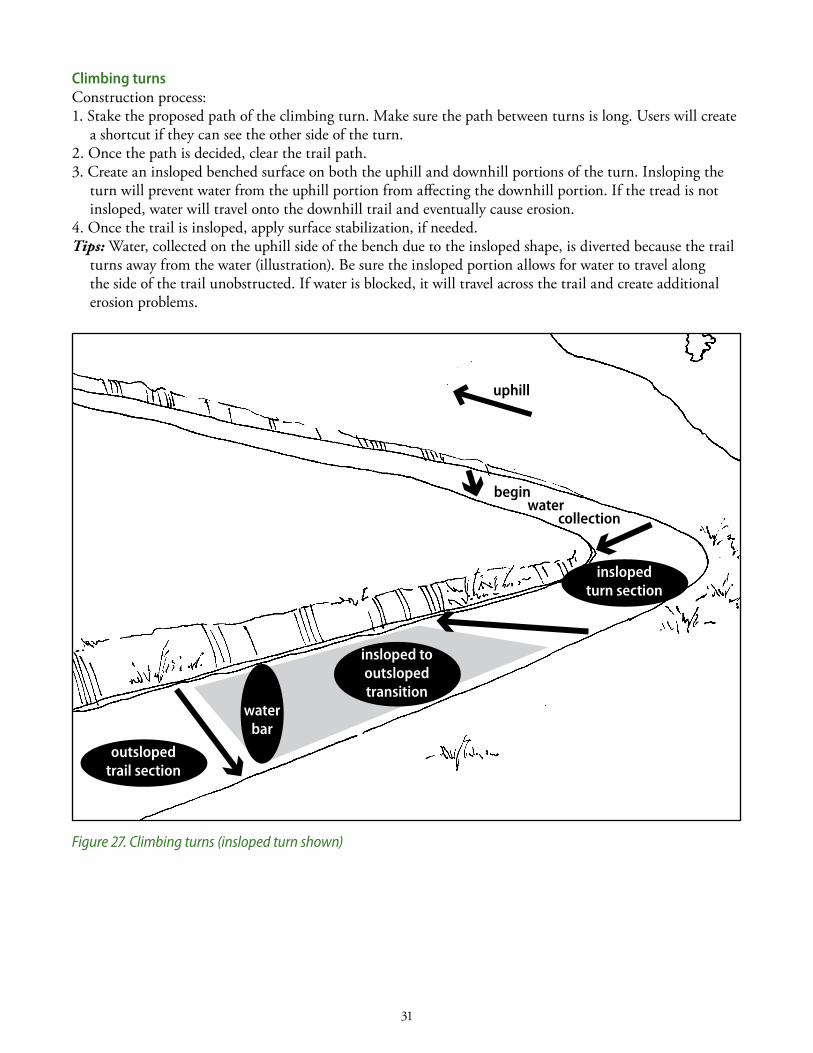
climbing turns Construction process:1. stake the proposed path of the climbing turn. Make sure the path between turns is long. users will create
a shortcut if they can see the other side of the turn. 2. Once the path is decided, clear the trail path. 3. Create an insloped benched surface on both the uphill and downhill portions of the turn. insloping the
turn will prevent water from the uphill portion from affecting the downhill portion. if the tread is not insloped, water will travel onto the downhill trail and eventually cause erosion.
4. Once the trail is insloped, apply surface stabilization, if needed.Tips: Water, collected on the uphill side of the bench due to the insloped shape, is diverted because the trail
turns away from the water (illustration). Be sure the insloped portion allows for water to travel along the side of the trail unobstructed. if water is blocked, it will travel across the trail and create additional erosion problems.
Figure 27. Climbing turns (insloped turn shown)
31
inslopedturn section
outslopedtrail section
insloped tooutslopedtransition
waterbar
begin water collection
uphill
32
aPPen D Ix a tR aI l- R ID eR an D H o R se beHaV I o R s to co nsID eRIn tR aIl- co ns tRUc tI o n PRoj ec t s
offered by George Hartman
With a keen interest in both horse and trail-rider behaviors, i offer these observations from 10 years on the trail. Consider these suggestions for working with the equine-using public when and where they
will enhance your trail-construction and -maintenance program.
Rider behaviorsMost problems from horse-trail users result from riders’ perceptions of what their horses want, horses
that lack training or riders who are inadequately trained to handle their horses. There is, of course, a wide variety of personalities and abilities among trail riders. if you consider these behaviors when designing or correcting existing trail problems, your constituents will be more satisfied and your trails may last longer.
Different trails for different types. You cannot make all riders happy with one type of trail, so manage for the best trail types suited to your soils and topography. Whatever trail surfaces and widths fit your management program, be assured that at least a segment of the trail riders will enjoy them.
Trail riders go to water. Horses do not need or want to drink every time they come to water, but some riders will take their horses to water at every opportunity. Consider this when a planned trail crosses a flowing or intermittent stream or passes close to a pond or lake. screen the trail from the water, make access to the water difficult or develop a watering area that will withstand usage by horses.
Decrease temptation. if riders can see another trail or something of interest from the backs of their horses, some will ride over to investigate or to reach the other trail. That is how many unauthorized trails begin. Consider the line of sight from your trail at a height of about 8 feet (rider on horse). This is especially important on switchback trails or where trails pass close to an attraction such as a cave, stream or scenic overlook. if you want riders to access these attractions, provide an access. Otherwise, don’t tempt riders to leave the existing trail. They will.
Keep them clear. Riders will go around low-hanging branches and may get off the trail. They will ride around downed trees, wet areas or deep ruts—all actions that cause a braided trail. Be vigilant about keeping the trail height and width open and dry so that riders can follow the designated trail.
Horse behaviors under the best of circumstances, a horse—as an evolutionary prey species—has some behaviors that will
show up in all but the most well-trained trail animals. They have evolved with their sight, hearing and smell to warn them of danger and their legs to get them away from any real or perceived danger. Their response to anything out of the ordinary is to perceive it as a potential threat. Any trail situation that could impede their escape from a predator also makes them anxious.
The following horse behaviors or responses to stimuli cannot be avoided. However, if they are addressed whenever practical, the chances of horses giving their riders control problems will decrease.
Tender feet. some horses are more tender-footed than others, even with shoes. When a horse is on rocks that are either painful to its feet or that make walking more difficult, they perceive their ability to escape from predators as restricted. This will make some horses more nervous. i recommend the top coating of trails to be one-inch minus-sized materials and, preferably, packed down.
Attention getters. Horses show concern toward things that move quickly, such as flapping bags, tarps or flags. They also notice objects that stand out from their surroundings, such as contrasting colors of construction materials.
Noises make them nervous. Horses are excited by out-of-the-ordinary noises, such as engaged construction equipment or the sound of their own feet walking over a bridge.
What’s in there? if a horse sees something that looks like a den or hiding place, it may be wary. Road culverts, where the openings are visible from either approach, could be harboring danger—in a horse’s mind.
33
aPPen D Ix b D e teR M In InG so Il te x tUR e— fI elD M e tH o D
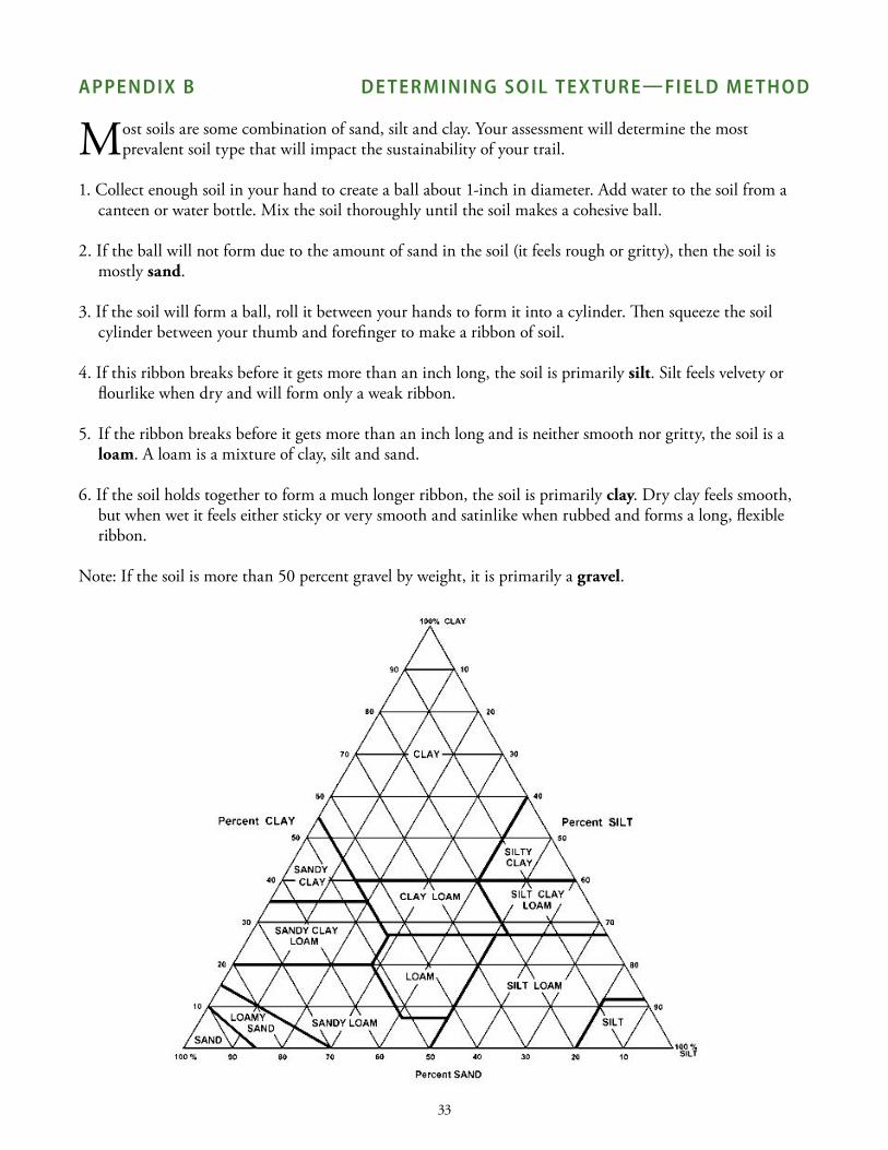
Most soils are some combination of sand, silt and clay. Your assessment will determine the most prevalent soil type that will impact the sustainability of your trail.
1. Collect enough soil in your hand to create a ball about 1-inch in diameter. Add water to the soil from a canteen or water bottle. Mix the soil thoroughly until the soil makes a cohesive ball.
2. if the ball will not form due to the amount of sand in the soil (it feels rough or gritty), then the soil is mostly sand.
3. if the soil will form a ball, roll it between your hands to form it into a cylinder. Then squeeze the soil cylinder between your thumb and forefinger to make a ribbon of soil.
4. if this ribbon breaks before it gets more than an inch long, the soil is primarily silt. silt feels velvety or flourlike when dry and will form only a weak ribbon.
5. if the ribbon breaks before it gets more than an inch long and is neither smooth nor gritty, the soil is a loam. A loam is a mixture of clay, silt and sand.
6. if the soil holds together to form a much longer ribbon, the soil is primarily clay. dry clay feels smooth, but when wet it feels either sticky or very smooth and satinlike when rubbed and forms a long, flexible ribbon.
note: if the soil is more than 50 percent gravel by weight, it is primarily a gravel.
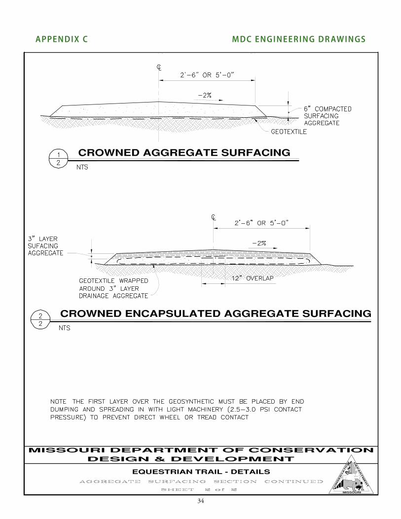
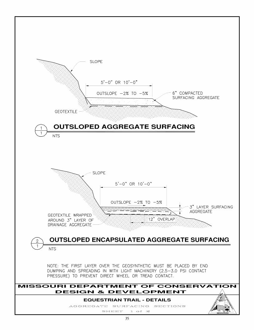
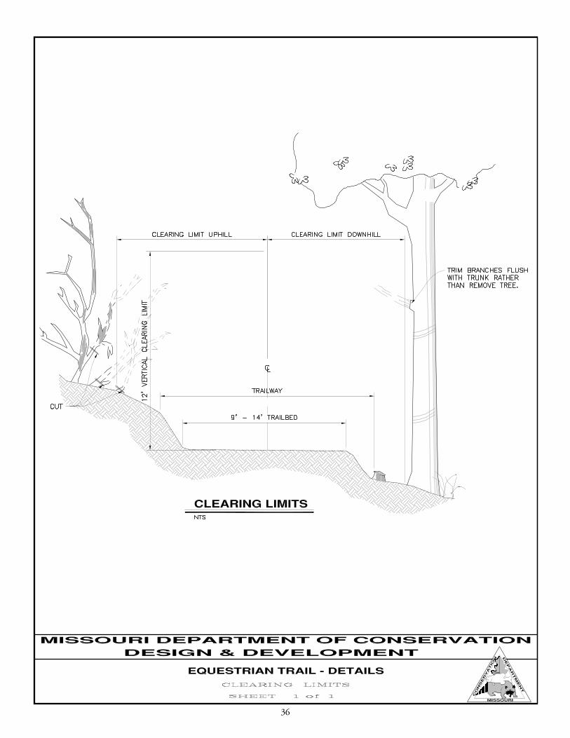
aPPen D Ix c M D c en G I n eeR I nG D R aWIn Gs
34
35
36
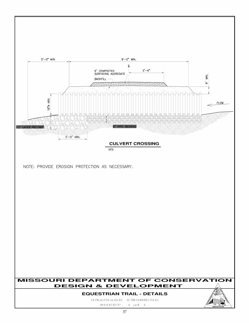
37
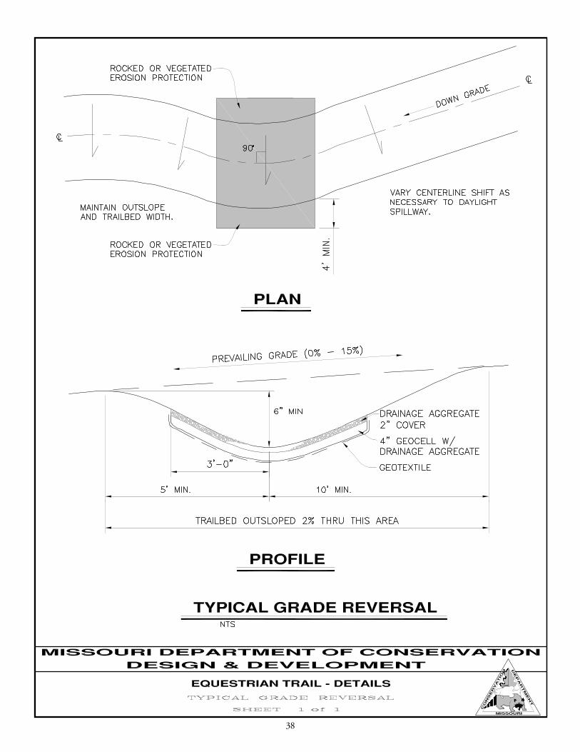
38
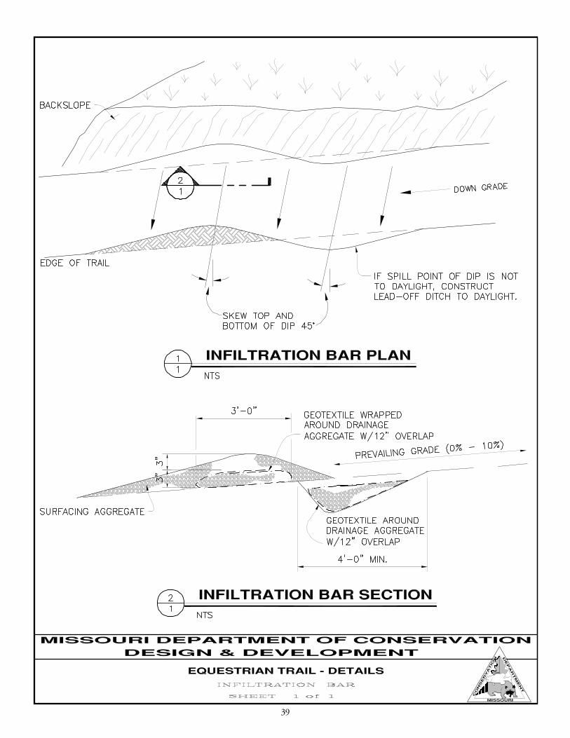
39
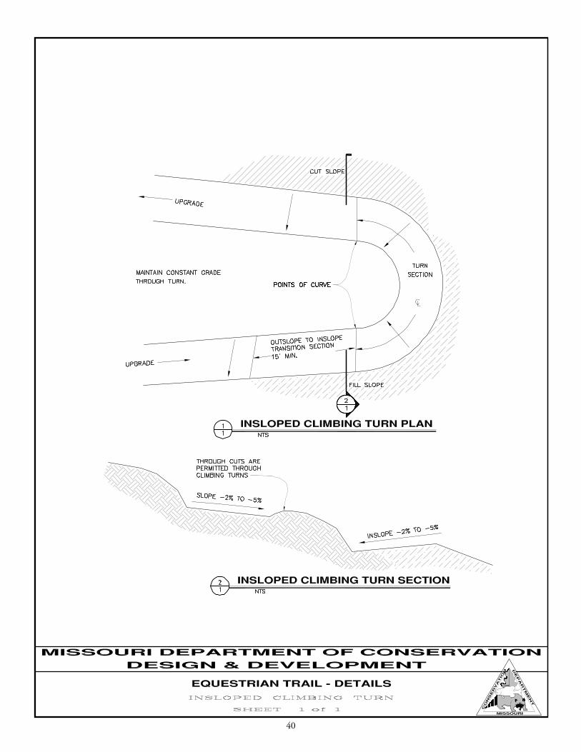
40
41
42
43
44
45
aPPen D Ix D tR aIl cos t e s tIM ate s
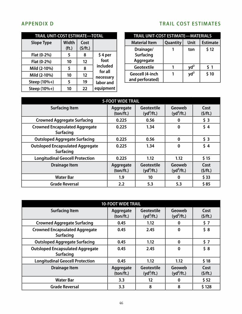
tRaIl UnIt-cost estIMate—total slope type Width
(ft.)cost
($/ft.)flat (0-2%) 5 8 $ 4 per
foot included
for all necessary labor and
equipment
flat (0-2%) 10 12Mild (2-10%) 5 8Mild (2-10%) 10 12steep (10%+) 5 19steep (10%+) 10 22
tRaIl UnIt-cost estIMate—MateRIalsMaterial Item Quantity Unit estimate
Drainage/surfacing
aggregate
1 ton $ 12
Geotextile 1 yd² $ 1Geocell (4-inch and perforated)
1 yd² $ 10
5-foot WIDe tRaIlsurfacing Item aggregate
(ton/ft.)Geotextile
(yd²/ft.)Geoweb(yd²/ft.)
cost($/ft.)
crowned aggregate surfacing 0.225 0.56 0 $ 3crowned encapsulated aggregate
surfacing0.225 1.34 0 $ 4
outsloped aggregate surfacing 0.225 0.56 0 $ 3outsloped encapsulated aggregate
surfacing0.225 1.34 0 $ 4
longitudinal Geocell Protection 0.225 1.12 1.12 $ 15Drainage Item aggregate
(ton/ft.)Geotextile
(yd²/ft.)Geoweb(yd²/ft.)
cost($/ft.)
Water bar 1.9 10 0 $ 33Grade Reversal 2.2 5.3 5.3 $ 85
10-foot WIDe tRaIlsurfacing Item aggregate
(ton/ft.)Geotextile
(yd²/ft.)Geoweb(yd²/ft.)
cost($/ft.)
crowned aggregate surfacing 0.45 1.12 0 $ 7crowned encapsulated aggregate
surfacing0.45 2.45 0 $ 8
outsloped aggregate surfacing 0.45 1.12 0 $ 7outsloped encapsulated aggregate
surfacing0.45 2.45 0 $ 8
longitudinal Geocell Protection 0.45 1.12 1.12 $ 18Drainage Item aggregate
(ton/ft.)Geotextile
(yd²/ft.)Geoweb(yd²/ft.)
cost($/ft.)
Water bar 3.3 12 0 $ 52Grade Reversal 3.3 8 8 $ 128
46
47
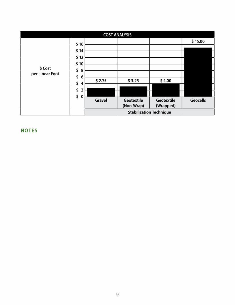
cost analYsIs
$ cost per linear foot
$ 16$ 14$ 12$ 10$ 8$ 6$ 4$ 2$ 0
$ 15.00
$ 2.75 $ 3.25 $ 4.00
Gravel Geotextile(non-Wrap)
Geotextile(Wrapped)
Geocells
stabilization technique
n ote s

48
n ote s