equipment and solutions - vector infotech
TRANSCRIPT

[formally technor atex ]
Solution
Equipment and Solutions


Subject to errors or changes
Editing completed January 2016

2 Ex-tech Solution
Ex-tech Group is located at Forus in Stavanger, Norway, one of the world’s top
Centers of Excellence within knowledge and technology related to the Oil and
Gas industry.
Our main office has all oil majors and NOC is located in close proximity.
Our engineers, with experience from the oil and gas industry, are used to the
strictest demands and specifications.
The group consist of three fully owned subsidiaries, each with different
competence and skills, enabling the group to be a complete and preferred
supplier and partner in the Ex market.

Ex-tech Solution is our French
subsidiary.
The company (formerly
Schneider Electric) has for
more than 40 years been
manufacturing a wide range
of Ex components, equipment
and solutions for the Oil & Gas
onshore market.
From small Ex switches and
lamps to large Ex d enclosures
for complex systems. A close
and fruitful collaboration with
French industry and local sub-
suppliers.
Ex-tech System is our subsidiary
in Norway, representing the
center of Excellence within
systems & solutions for the Oil &
Gas offshore market.
The company is offering a
wide range of components
and enclosures to complex
Ex systems, including a close
collaboration with sub-suppliers.
In addition the company has a
long tradition and experience in
converting industrial electrical
and combustion machines to be
used in explosive atmospheres.
Ex-tech Signalling is our
second subsidiary in France.
The company represents the
groups center of excellence
related to audio and visual
signalling equipment, used
mainly for signalling in
combination with Fire & Gas as
well as Telecom systems.
3 Ex-tech Solution

Motor starters, motor switches
The 3 poles motor starters in protection modes Ex d IIB or Ex
IIC meet all your needs for from 0.37 up to 37 kW.
The wide range of enclosures combined with a wide range of
contractors, thermal relays, allows real flexibility to adapt.The disconnector switches in increased safety Ex e, easy to
implement, provides range of switching capacity from 20 A to
63 A and operating temperatures from -50 °C to +60 °C.
Systems and panels for control and monitoring
The flameproof enclosures are designed for control, monitoring, automation, distribution board, motor starters or any other application.
Made in carbon steel, aluminium or stainless steel for gas groups IIB or IIB+H2 or IIC with a wide range of sizes: up to 1590 x 940 mm for a dissipated power of 2000 W, they are suitable for the design of complex systems.
Junction boxesThe junction boxes are provided in flameproof protection mode Ex d IIB or IIC or in increased safety Ex e IIC.
Made in GRP, aluminium, cast iron or stainless steel, they are suitable for environments with the presence of chemical agents, corrosion resistants, operating temperatures from -50 °C to +60 °C/+75 °C.
They are equipped with terminals or push buttons, switches, pilot lights and measuring instruments.
Luminaires
A range of lighting fixtures 100% encapsulated, maintenance-free requiring only a visual inspection, designed with a body
seawater resistant in anodized aluminium (in accordance with
NORSOK 121), very easy and quick to install.
They are condensation free and have a tempered glass with
very high impact resistance IK 20 and warranted 10 years.
Limit switches, photocells, pressure switches
The range of limit switches and pressure switches (from 0.1
to 500 bars) to control in a safe way movements, fluids in hazardous areas. The range is one of the most extensive in
the market.
With a footprint of only 30 mm in diameter, our photocells are
pre-wired and certified ATEX Ex d.
Control stations and signalling units
The XAW control stations are equipped with our extensive range of our wide control and signalling units HarmAtex
They combine the functions start and stop for motors, as
fans, pumps, ... and they can be provided with measuring
instruments for current control, voltage or other physical
quantities.
4 Ex-tech Solution
Audible and visual signalling devices
A full range of Sounders, Beacons, Call-point, or Junction box,
well adapted to your applications.
Each range is available with housing in stainless steel or GRP,
full range of voltage supply exist.

Content
Ex regulations 6
Atex and IECEx regulations
IP rating
IK rating
Control stations 21
Increased safety - Polyester, aluminium, stainless steel
Flameproof - Aluminium - Gas group IIB and IIC
Increased safety - Pendant stations
Increased safety - Fire control station
Control and signalling units HarmAtex 39
Push buttons, emergency stops, selector switches, pilot lights, illuminated
Foot switches
Pull-wire switches
Motor starters - Motor switches 59
Flameproof Motor starters - Gas group IIB and IIC
Increased safety Motor switches
Junction boxes 67
Increased safety - Polyester, aluminium, stainless steel
Flameproof - Iron or aluminium - Gas group IIB or IIC
Flameproof - Aluminium - Large boxes - Gas group IIB
Flameproof enclosures gas group IIB + H2
or IIC, Ex e cabinets 81
Heavy series IIB + H2 - Carbon steel or stainless steel
Heavy series IIB + H2 with Ex e enclosure - Carbon steel or stainless steel
Aluminium or stainless steel IIB + H2 series
Aluminium or stainless steel IIB + H2 with Ex e enclosure
Carbon steel or stainless steel - Group IIC series
Carbon steel or stainless steel - Group IIC series with Ex E enclosure
Increased safety control cabinets - Painted steel or stainless steel
Lighting 103
Durable lighting fixtures
Sensors - Photocells - Pressure switches 109
Limit switches - Flameproof - Group IIC
Limit switches - Increased safety
Photocells - Flameproof - Group IIC
Pressures switches - Flameproof - - Group IIC
Cable glands 129
Cable glands in polymide or brass nickel plated
Ex-tech Signalling products 135
Beacons / light
Sounders / horns
Sounders and beacons
Combined products
Status lights
Manual call points
Push buttons
Junction boxes
Accessories and spare parts
5 Ex-tech Solution

Oxygenin the air
Flammablesubstances
Ignitionsource
Explosion
An explosive atmosphere is a result of the mixture with air, under atmospheric conditions and flammable substances in the form of gas, vapours, dusts, fibers which, once ignited, allow the combustion process to spread and permits self-sustaining propagation.
Explosive atmosphere can be encountered, as result of technical processing sequences, in several industries such as:
petrochemical, mills and silos generating combustible dust, in mining by the methane gas and coal dust. Further areas
can develop explosive atmosphere like: paint industry, recycling industry, production of biogas.
The conditions for creating an explosion are: air, flammable substances and ignition source.
There are two main principles to avoid an explosion: primary and secondary precautions.
The primary explosion protections are the measures to take to prevent the creation of an explosive atmosphere:
- Measures using natural or forced ventilation to limit the explosive concentration
- Measures avoiding flammable substances- Measures using inert gas in the atmosphere (e.g. Nitrogen)
The secondary explosion protections are the measures to prevent the ignition of an explosive atmosphere.
Type of Ignition Sources
• Hot surfaces
• Flames and hot gases
• Mechanically produced sparks
• Electrical equipment
• Transient currents
• Static electricity
• Lightning strikes
• Electromagnetic waves
• Optical radiation
• Ultrasound
• Chemical reactions
• People (indirectly)
The techniques of equipment protection for use in explosive atmospheres are just a matter of controlling
(eliminating) possible ignition sources (secondary explosion protection)
6 Ex-tech Solution
1. General information
2. Explosion

Where do we find explosive atmospheres?
• Metal surface grinding, especially aluminium dust and particles
• Oil refineries, rigs and processing plants• Gas pipelines and distribution centres
• Printing industries, paper and textiles
• Aircraft refuelling and hangars
• Chemical processing plants
• Grain handling and storage
• Sewage treatment plants
• Surface coating industries
• Underground coal mines
• Woodworking areas
• Sugar refineries• Vessels/ships
• Power plants
7 Ex-tech Solution
Where a potential explosive atmosphere can occur, certain safety levels need to be taken into account regarding the
possible danger of an explosion in this area. The areas therefore need to be divided into zones according to presence
of the flammable substances.
Zone 0 Zone 1 Zone 2
A place in which an explosive atmosphere
consisting of a mixture with air of
flammable substances in the form of gas, vapour or mist is present continuously or
for long periods or frequently.
Explosive atmosphere for more than 1000
h/yr.
A place in which an explosive atmosphere
consisting of a mixture with air or
flammable substances in the form of gas, vapour or mist is likely to occur in normal
operation occasionally.
Explosive atmosphere for more than 10,
but less than 1000 h/yr.
A place in which an explosive atmosphere
consisting of a mixture with air of
flammable substances in the form of gas, vapour or mist is not likely to occur in
normal operation, but - if it does occur - will
persist for a short period only.
Explosive atmosphere for less than 10 h/yr
Zone 20 Zone 21 Zone 22
A place in which an explosive atmosphere
in the form of cloud of combustible dust
in air is present continuously, or for long
periods or frequently.
A place in which an explosive atmosphere
in the form of a cloud of combustible dust
in air is likely to occur in normal operation
occasionally.
A place in which an explosive atmosphere
in the form of a cloud of combustible
dust in air is not likely to occur in normal
operation, but - if it does occur - will persist
for a short period only.
3. Explosive atmosphere

Examples of the criteria for the mixture of flammable substances (gas) towards air in such a way that an explosion can occur are:
Typical concentration of gas/vapours in the air where an explosion can appear (% vol. of gas in air):
1. LEL (Lower Explosion Limit)
2. UEL (Upper Explosion Limit)
3. Optimum mixture
4. MIE (Minimum Ignition Energy)
µJ
%
1
2
3
4
Volume in percent
gas/vapour in air
Ignition Energy
LEL Explosion UEL
Methane 4.4% 16.5%Propane 1.7% 10.6%Butane 1.4% 9.3%
4. Criteria of flammable substances
8 Ex-tech Solution
100 Vol % Concentration of Air 0 Vol %
Mixture too lean Explosion range Mixture too rich
Explosion limit
Lower Higher
0% 100% LEL (1) UEL (1)
0 Vol % Concentration of flammable substances 100 Vol %
(1) LEL (Lower Explosive Limit) UEL (Upper Explosive Limit)

- Product Directive 1994/9/EC
- New product Directive 2014/34/EU
- User Directive 1999/92/EC
5.1 Equipment Directive 1994/9/EC
This directive has been mandatory in Europe from 01.07.2003, and covers the regulations concerning equipment and
protective systems for use in potentially explosive atmospheres. This directive has four chapters which are subdivided
into 16 articles. In each chapter it is made reference to the Annex I to XI, which include 7 modules.
For full info visit http://ec.europa.eu/enterprise/atex/internationaldevelopment.htm
Content of directive 94/9/EC
Main part
Chapter Article Heading
I 1 - 7 Scope of application, placed in service and free movement of goods
II 8 - 9 Conformity assessment procedures
III 10 - 11 CE marking of conformity
IV 12 - 16 Concluding provisions
Annexes
I Criteria determining the classification decision of equipment groups in categories
IIEssential safety and health requirements for the design and construction of equipment and
protective systems for use in potentially explosive atmospheres
III Module: EC-type examination
IV Module: Production Quality assurance
V Module: Product verificationVI Module: Conformity to type
VII Module: Product Quality assurance
VIII Module: Internal control of production
IX Module: Unit verificationX CE marking and contents of the EC declaration of conformity
XI Minimum criteria to be taken into account by member states for the notification of bodies
5. ATEX Directives
9 Ex-tech Solution
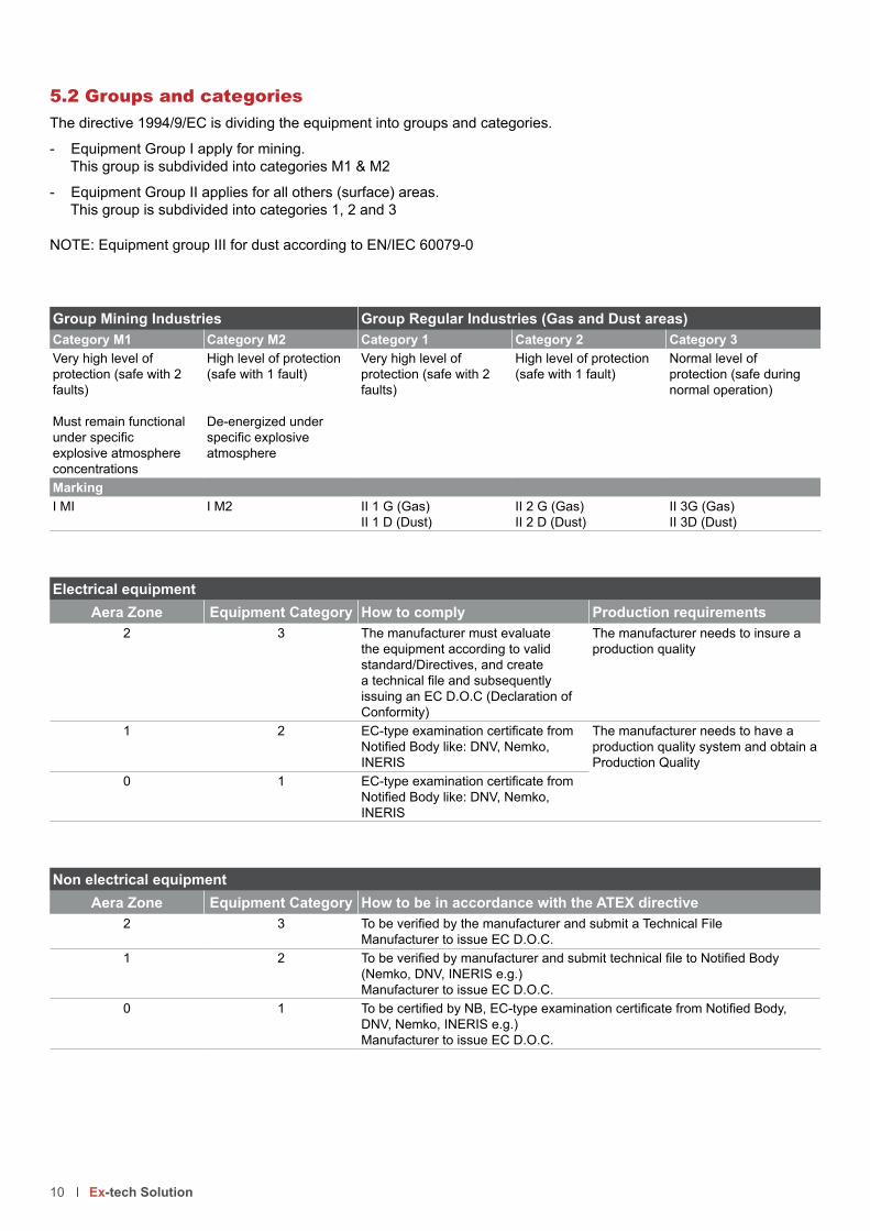
5.2 Groups and categories
The directive 1994/9/EC is dividing the equipment into groups and categories.
- Equipment Group I apply for mining.
This group is subdivided into categories M1 & M2
- Equipment Group II applies for all others (surface) areas.
This group is subdivided into categories 1, 2 and 3
NOTE: Equipment group III for dust according to EN/IEC 60079-0
Group Mining Industries Group Regular Industries (Gas and Dust areas)
Category M1 Category M2 Category 1 Category 2 Category 3
Very high level of
protection (safe with 2
faults)
Must remain functional
under specific explosive atmosphere
concentrations
High level of protection
(safe with 1 fault)
De-energized under
specific explosive atmosphere
Very high level of
protection (safe with 2
faults)
High level of protection
(safe with 1 fault)
Normal level of
protection (safe during
normal operation)
Marking
I MI I M2 II 1 G (Gas)
II 1 D (Dust)
II 2 G (Gas)
II 2 D (Dust)
II 3G (Gas)
II 3D (Dust)
Electrical equipment
Aera Zone Equipment Category How to comply Production requirements
2 3 The manufacturer must evaluate
the equipment according to valid
standard/Directives, and create
a technical file and subsequently issuing an EC D.O.C (Declaration of
Conformity)
The manufacturer needs to insure a
production quality
1 2 EC-type examination certificate from Notified Body like: DNV, Nemko, INERIS
The manufacturer needs to have a
production quality system and obtain a
Production Quality
0 1 EC-type examination certificate from Notified Body like: DNV, Nemko, INERIS
Non electrical equipment
Aera Zone Equipment Category How to be in accordance with the ATEX directive
2 3 To be verified by the manufacturer and submit a Technical FileManufacturer to issue EC D.O.C.
1 2 To be verified by manufacturer and submit technical file to Notified Body (Nemko, DNV, INERIS e.g.)
Manufacturer to issue EC D.O.C.
0 1 To be certified by NB, EC-type examination certificate from Notified Body, DNV, Nemko, INERIS e.g.)
Manufacturer to issue EC D.O.C.
10 Ex-tech Solution

Note:
The equipment also needs to be marked with the conventional protection mode (Ex…) according to EN/IEC 60079-0
(EN/IEC 61241-0 (60079-31 for dust atmospheres or 80079-36 for non-electrical).
The operating instructions manual of the manufacturer must clearly define the intended use of the equipment by the operator. The minimum requirements for the operating instruction are amongst others:
- Information about safety aspects
- Installation, putting into service, use
- Assembling and dismantling, maintenance (servicing and emergency repair)
- Adjustment
5.3 Marking
11 Ex-tech Solution
1 Manufacturer name
2 Conformity mark with identification number of the Notified Body3 Ex mark
4 Equipment group II
5 Equipment category 2 - Gas/Vapours and Dust
6 Product code
7 Product serial number
8 Certificate number according to ATEX standards9 Certificate number according to IECEx standards
10 Ambient temperature range
Marking for Gas/Vapours
11 Electrical apparatus to be installed in hazardous location
12 Type of protection: flameproof enclosure13 Explosion gas group IIB
14 Temperature class T6
15 Equipment protection level Gb (high protection level) - Use in zone 1 and 2
Marking for Dust
16 Electrical apparatus to be installed in hazardous location
17 Type of protection: protection by enclosure
18 Explosion dust group IIIC (conductive types of dust)
19 Maximum surface temperature 85 °C
20 Equipment protection level Db (high protection level) - Use in zone 1 and 2
21 IP protection
0080 II 2GD
DE8BC64 INERIS 03ATEX0005X N° xxxxxxxxxxxx IECEx INE 13.0045X Ex d IIB T6 Gb -- Ex tb IIIC T85°C Db IP65-66 -20°C <Ta< +40°C
DO NOT OPEN WHEN ENERGIZED
21
15
3
14
4 5
6 8
9
11
7
12
10
13 16 17 18 19 20 21
5.5 New ATEX Directive 2014 applicable from the 20th of April 2016
The new ATEX Directive 2014/34/EU on equipment and protective systems intended for use potentially explosive atmospheres is aligned with the “New Legislative Framework” and will be applicable from 20 April 2016.
There is no change to the Essential Requirements of Health and Safety as defined in Annex II. There is also no change in the various evaluation procedures. The terms of Annexes of the Directive, however, are modified.
Key changes against the old 94/9/EC directive:
• The directive also requires traceability of a product to be ensured throughout the whole supply chain. Therefore
this directive clarifies requirements for manufacturers, authorized representatives, importers and distributors to make sure that products they place on the market comply with this directive
• From 20 April 2016 all products placed on the marked need to comply with 2014/34/EU and a EU DOC
(Declaration Of Conformity ) need to be issued. Also the user instruction need to be revised by referring to the
new directive
• All new certificates issued after 19 April 2016 will be named EU-Type Examination Certificate
Note:All certificates issued according to 94/9/EC will still be valid if the products comply with 2014/34/EU ( state of the art) and a EU DOC ( Declaration Of Conformity ) is issued before they are placed on the marked. The New directive will
not apply for products already placed on the marked.
You will find further information on: http://eur-lex.europa.eu/legal-content/EN/TXT/?uri=CELEX:32014L0034
5.6 User Directive 1999/92/EC
This directive gives the minimum requirement for improving the safety and health protection of workers potentially at
risk from explosive atmospheres.
The main issues to be addressed:
• Assessment of explosion risk
• Zone classification• Explosion protection documents (including requirements for personnel to do engineering, equipment selection,
installation, maintenance, repair, etc.)
12 Ex-tech Solution
5.4 Manufacturer’s Declaration of conformity
Equipment and protective systems can be placed on the market, only if marked with the CE mark and complete with
operating instructions and the manufacturer’s Declaration of Conformity. The CE conformity marking and the issued
Declaration of Conformity confirm that the equipment complies with all requirements and assessment procedures specified in the EC Directives. Essential in the EC DOC is the harmonized standards ref; http://eurlex.europa.eu/legalcontent/EN/TXT/PDF/?uri=uriserv:OJ.C_.2014.445.01.0005.01.ENG
Note:
According to Directive 94/9/EC the mandatory evidence of complying with this is given in the EC D.O.C.and the
marking plate on the products including the operating instructions.

5.7 Structure Directive 1999/92/EC
Ruling part
Section Article Heading
I 1 - 2 General provisions
II 3 - 9 Obligations of the employer
3 Prevention of and protection against explosions
4 Assessment of the explosion risks
5 General obligations
6 Duty of coordination
7 Places where explosive atmosphere may occur
8 Explosion protection document
9 Special requirements for work equipment and workplaces
III 10- 15 Other requirements
Annexes
I Classification of places where explosive atmospheres may occur1. Places where explosive atmospheres may occur
2. Classification of hazardous placesII A Minimum requirements for the improvement of the safety and health protection of employees
who could be endangered by explosive atmospheres
1. Organizational measures
2. Explosion protection measures
B Criteria for the selection of equipment and protective systems
III Warning signs for marking areas in which explosive atmospheres can occur
For further information (Directive 1999/92/EC and user guide) please visit:
http://ec.europa.eu/employment_social/health_safety/legislation_en.htm
13 Ex-tech Solution

6.3 Energy class
Minimum ignition energy European groups USA / Canada Groups Gas e.g.
< 20 µ JoulesC
A Acetylene, Carbon disulfide< 20 µ Joules B Hydrogen
< 60 µ Joules B C Ethyl ether, Ethylene
< 180 µ Joules A DAcetone, Butane, Ethanol, Gasoline, Hexane,
Methanol, Methane, Naphta, Propane
14 Ex-tech Solution
6. Ignition sources
6.1 Classification of ignition sources for gas and vapours
Hot SurfacesIgnition Temperature
SparksIgnition Energy
Temperature ClassT1 ... T6
Gas GroupA .... C
6.2 Temperature class
Temperature class Maximum surface temperature at ambient temperature
T1 450 °C
T2 300°C
T3 200°C
T4 135°C
T5 100°C
T6 85°C

7.1 Standards valid for gas
Electrical Apparatus for Explosive Gas Atmospheres
EN (old) EN / IEC (Current)
General requirements EN 50 014 EN 60079-0
Flameproof enclosures “d” EN 50 018 EN 60079-1
Pressurized enclosures “p“ EN 50 016 EN 60079-2
Powder filling “q“ EN 50 017 EN 60079-5
Oil immersion “o” EN 50 015 EN 60079-6
Increased safety “e” EN 50 019 EN 60079-7
Intrinsic safety “i” EN 50 020 EN 60079-11
Type of protection “n” EN 50 021 EN 60079-15
Encapsulation “m” EN 50 028 EN 60079-18
Intrinsically safe systems EN 60079-25
Electrical equipment for Zone 0 EN 50 284 EN 60079-26
Intrinsically safe field bus systems EN 60079-27
Optical radiation “op” EN 60079-28
7. Standards
7.2 Standards valid for dust
Standard EN (IEC) Protection name Protection method
EN (IEC) 60079-31 t Equipment , Dust ignition protection by enclosures “t”
61241-4 pD Protected by pressurization
7.3 Standards valid for non-electrical equipment
Protection type EN 13463- Marking letter New coming standards
Basic methods and requirements -1 (EN) ISO/ IEC - 80079-36
Flow restriction -2 fr
Flameproof -3 d
Construction -5 c(EN) ISO/ IEC - 80079-37
Controlled ignition -6 b
Protected by oil -8 k
7.4 Standards valid for internal combustion motors
EN 1834-1 Gas, group II
EN 1834-2 Mines, group I
EN 1834-3 Dust, group II
15 Ex-tech Solution
7.5 Standards valid for safety industrial truck
EN 1755
Operation in potentially explosive atmosphere
16 Ex-tech Solution
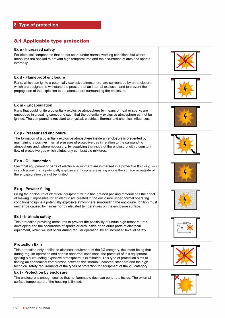
8.1 Applicable type protection
Ex e - Increased safety
For electrical components that do not spark under normal working conditions but where
measures are applied to prevent high temperatures and the occurrence of arcs and sparks
internally.
Ex d - Flameproof enclosure
Parts, which can ignite a potentially explosive atmosphere, are surrounded by an enclosure,
which are designed to withstand the pressure of an internal explosion and to prevent the
propagation of the explosion to the atmosphere surrounding the enclosure.
Ex m - Encapsulation
Parts that could ignite a potentially explosive atmosphere by means of heat or sparks are
embedded in a sealing compound such that the potentially explosive atmosphere cannot be
ignited. The compound is resistant to physical, electrical, thermal and chemical influences.
Ex p - Pressurized enclosure
The formation of a potentially explosive atmosphere inside an enclosure is prevented by
maintaining a positive internal pressure of protective gas in relation to the surrounding
atmosphere and, where necessary, by supplying the inside of the enclosure with a constant
flow of protective gas which dilutes any combustible mixtures.
Ex o - Oil immersion
Electrical equipment or parts of electrical equipment are immersed in a protective fluid (e.g. oil) in such a way that a potentially explosive atmosphere existing above the surface or outside of
the encapsulation cannot be ignited.
Ex q - Powder fillingFilling the enclosure of electrical equipment with a fine grained packing material has the effect of making it impossible for an electric arc created in the enclosure under normal operating
conditions to ignite a potentially explosive atmosphere surrounding the enclosure. Ignition must
neither be caused by flames nor by elevated temperatures on the enclosure surface.
Ex i - Intrinsic safety
This protection providing measures to prevent the possibility of undue high temperatures
developing and the occurrence of sparks or arcs inside or on outer parts of electrical
equipment, which will not occur during regular operation, by an increased level of safety
Protection Ex n
This protection only applies to electrical equipment of the 3G category, the intent being that
during regular operation and certain abnormal conditions, the potential of this equipment
igniting a surrounding explosive atmosphere is eliminated. This type of protection aims at
finding an economical compromise between the “normal” industrial standard and the high technical safety requirements of the types of protection for equipment of the 2G category.
Ex t - Protection by enclosure
The enclosure is enough seal so that no flammable dust can penetrate inside. The external surface temperature of the housing is limited.
8. Type of protection

8.2 Equipment Protection Level (EPL) according to IEC/EN 60079-xx series
OD standards
Definition:
The level of protection assigned to equipment based on its risk of becoming a source of ignition, and distinguishing
the differences between explosive gas atmospheres, explosive dust atmospheres, and the explosive atmospheres
which may exist in coal mines.
8.2 Link between ATEX and EPL
EN 60079-0 Directive 94-9-EC Product directive (Atex 100)
EN60079-10X Directive 99/92/EC User directive (Atex 137)
EPL Group Level of protection
Equipment group
Equipment category
Zones Hazardous quantities Extent of protective measure (risk)
Ma
I
Very high
I
M1 N/AWithout specific methane concentration
Safe with 2 faults, rare
and foreseen
Mb High M2With specific methane concentration
Safe with 1 fault,
foreseen
Ga
II
Very high
II
1G 0 Often/longer periodsSafe with 2 faults, rare
and foreseen
Gb High 2G 1 OccasionallySafe with 1 fault,
foreseen
Gc Enhanced 3G 2 Rear/most likely never Normal
Da
III
Very high 1D 20 Often/longer periodsSafe with 2 faults, rare
and foreseen
Db High 2D 21 OccasionallySafe with 1 fault,
foreseen
Dc Enhanced 3D 22 Rear/most likely never Normal
8.3 Why EPL (ATEX categories)
Historically it has been acceptable to install equipment into specific zones based on the type of protection.
In some cases it has been shown that the type of protection may been divided into different levels of protection that can
be correlated against each Zone. A better risk assessment would consider all factors.
When using a risk assessment approach instead of the inflexible approach of the past linking equipment to Zones the inherent ignition risk of the equipment is clearly indicated, no matter what type of protection is used.
An example using a risk assessment approach:
Plant operators often make intuitive decisions on extending (or restricting) their Zones in order to compensate for this
inflexibility. A typical example is the installation of “Zone 1 Type” navigation equipment in Zone 2 areas of offshore oil production platforms, so that the navigation equipment can remain functional even in the presence of a totally
unexpected and prolonged gas release.
On the other hand, it is reasonable for the owner of a remote, well secured, small pumping station to drive the pump
with a “Zone 2 Type” motor, even in Zone 1, if the total amount of gas available to explode is small and the risk to life
and property from such as explosion can be discounted.
The situation became more complex with the publication of the first edition of IEC 60079-26 which introduced additional requirements to be applied for equipment intended to be used in Zone 0. Prior to this, Ex ia was considered to be the
only technique acceptable in Zone 0.
It has been recognized that it is beneficial to identify and mark all products according to their inherent ignition risk. This makes equipment selection easier and a risk assessment approach, more appropriate.
17 Ex-tech Solution

18 Ex-tech Solution
9. New marking for Ex equipment
9.1 New marking for Gas equipment
ATEX Old Gas atmosphere New IEC 60079-0:2011/EN 60079-0:2012
II 2 G Ex d IIB T6 Ex d IIB T6 Gb or Ex db IIB T6*
II 2(1) G Ex d [ia IIC] IIB T6 Ex d [ia IIC Ga] IIB T6 Gb or Ex db [ia IIC] IIB T6*
II 2 G Ex ib IIC T4 Ex ib IIC T4 Gb or Ex ib IIC T4*
II 2 G Ex e II T4 Ex e IIC T4 Gb or Ex eb IIC T4*
*IEC alternate marking
Protection principles and marking for explosive gas atmosphere
Marking according to EN (IEC) 60079-1: 21012
Alternative marking and coming marking
Equipment protection level (EPL) Ga Gb Gc Ga Gb Gc
Flameproof enclosure d da db dc
Increased safety e eb ec
Intrinsic safety ia ib ic ia ib ic
Encapsulation ma mb mc ma mb mc
Non-sparking nA nAc
Protected sparking nC nCc
Restricted sparking nR nRc
Oil immersion o ob oc
Pressurization px
py
pz
pv
pxb
pyb
PVC
pzv
Powder filling q qb
9.1 New marking for Dust equipment
ATEX Old Dust atmosphere New IEC 60079-0:2011/EN 60079-0:2012
II 2 D Ex tD A21 IP65 T120°C Ex tb IIIC T120°C Db or Ex tb IIIC T120°C*
II 2(1) D Ex tD [iaD] A21 IP65 T120°C Ex tb [ia Da] IIIC T120°C Db or Ex tb [ia] IIIC T120°C*
II 2 D Ex iaD A20 IP65 T120°C Ex ia IIIC T120°C Da or Ex ia IIIC T120°C*
Protection principles and marking for explosive dust atmosphere
Marking according to EN (IEC) 60079-1: 21012
Alternative marking and coming marking
Equipment protection level (EPL) Da Db Dc Da Db Dc
Protected by enclosure ta tb tc ta tb tc
Intrinsic safety ia ib ia ib ic
Encapsulation ma mb ma mb mc
Pressurization p p pb pc
*IEC alternate marking

19 Ex-tech Solution
10. IP protection
First digit: protection against solid particules Second digit: protection against liquid ingress
IP Protected against IP Protected against
0 No protection 0 No protection
1 Protected against a solid object 50 mm or greater 1 Protected against vertically dripping water
2 Protected against a solid object 12.5 mm or greater 2 Protected against vertically dripping water, when tilted 15
degrees
3 Protected against a solid object 2.5 mm or greater 3 Protected against water spraying at an angle up to 60
degree
4 Protected against a solid object 1 mm or greater 4 Protected against water splashing from any direction
5 Dust protected 5 Protected against jets of water from any directions
6 Dust tight 6 Protected against powerful jets of water from any
directions
7 Protected against temporary immersion into water up to
1 meter
8 Protected against prolonged immersion into water
beyond 1 meter
9K Protected against powerful high temperature water jets
IP code according to IEC/EN standard 60529
IK Impact energy (joules) Protected against
00 Unprotected No test
01 0.15 Drop of 200 g object from 7.5 cm height
02 0.2 Drop of 200 g object from 10 cm height
03 0.35 Drop of 200 g object from 17.5 cm height
04 0.5 Drop of 200 g object from 25 cm height
05 0.7 Drop of 200 g object from 35 cm height
06 1 Drop of 500 g object from 20 cm height
07 2 Drop of 500 g object from 40 cm height
08 5 Drop of 1.7 kg object from 29.5 cm height
09 10 Drop of 5 kg object from 20 cm height
10 20 Drop of 5 kg object from 40 cm height
11. IK protection
IK code according to EN 62252
The Ex marking for explosive gas and dust atmospheres shall be separate and not combined:
II 1 G - Ex ia IIB T4 Ga
II 1 D - Ex ia IIIC T120°C Da
alternatively
II 1 GD
Ex ia IIB T4 Ga
Ex ia IIIC T120°C Da
or
II 1 GD
Ex ia IIB T4
Ex ia IIIC T120°C

20 Ex-tech Solution

21 Ex-tech Solution
Control Stations
Content Page
Control Stations - Increased safety
Glass-reinforced polyester XAWG series 22
Aluminium XAWF series 24
Stainless steel XAWFS series 26
Control Stations - Flameproof
Aluminium XADW series - Explosion gas group IIB 28
Aluminium XAEW series - Explosion gas group IIC 28
Pendant Stations - Increased safety
Glass-reinforced polyester XAWP series 30
Fire Alarm Stations - Increased safety
Glass-reinforced polyester XAWS series 36

Control stationsIncreased safety - Group I ICGlass-reinforced polyester - XAWG series
The control stations XAWG, made in glass-reinforced polyester (GRP), are equipped with our extensive range of robust and flexible control and signalling units HarmAtex.
They combine the functions start and stop for motors, fans, pumps ...,
and they can be provided with measuring instruments for current control,
voltage or other physical quantities.
The functions can be predefined or determined according to the requirement of the application. Up to 48 control and signalling units can be
installed on the XAWG control units.
TECHNICAL DATA
Material Glass-reinforced polyester (GRP)
IP rating IP65 according to EN/IEC 60529
Temperature range -20°C ... +40°C or +50°C or +60°C
Certificate INERIS 03ATEX0122X
Marking II 2 GD
Ex e IIC T6...T4 Gb
Ex e mb IIC T6...T4 Gb
Ex d e IIC T6...T4 Gb
Ex d e mb IIC T6...T4 Gb
Ex tb IIIC T85°C ... T135°C Db
Features of the contact block Ith = 10 A; Ui = 415 V
AC Ue = 380 V; Ie = 1,9 A or Ue = 240 V; Ie = 3 A or Ue = 120 V; Ie = 6 ADC Ue = 250 V; Ie = 0,27 A or Ue = 125 V; Ie = 0,55 A or Ue = 24 V; Ie = 2,87 A
Features of the LED pilot light Rated voltage 24 ... 254 V AC/DC
Maximal current 2 ... 10 mA
Mechanical endurance of the push buttons Head: 5 million operations - Contact block: 1 million operations
Product code Actuator Colour Label Contact
XAWG10 1 x Push button, spring to return l Green Start 1NO
XAWG11 1 x Push button, spring to return l Red Stop 1NC
XAWG16 1 x Mushroom, spring to return - Ø 40 mm l Red Emergency stop 1NC
XAWG15 1 x Mushroom, Push-Pull - Ø 40 mm l Red Emergency stop 1NC
XAWG17 1 x Mushroom, turn to release - Ø 40 mm l Red Emergency stop 1NC
XAWG172 1 x Mushroom, release by key - Ø 40 mm l Red Emergency stop 1NC
XAWG13 1 x Selector switch, 2 stay put positions l Black Start - Stop 1NO
XAWG132 1 x Selector switch, 2 stay put positions l Black Manu - Auto 1NO+1NC
XAWG133 1 x Selector switch, 2 stay put positions l Black 0-I 1NO+1NC
XAWG12 1 x Selector switch, 3 stay put positions l Black I-0-II 1NO+1NC
XAWG121 1 x Selector switch, 3 spring return to center l Black I-0-II 1NO+1NC
XAWG122 1 x Selector switch, key withdrawal in 3 positions l Black I-0-II 1NO+1NC
XAWG143 1 x Pilot light, integral LED - 24 to 254 V AC-DC l Green Blank -
XAWG144 1 x Pilot light, integral LED - 24 to 254 V AC-DC l Red Blank -
XAWG147 1 x Pilot light, integral LED - 24 to 254 V AC-DC White Blank -
XAWG146 1 x Pilot light, integral LED - 24 to 254 V AC-DC l Blue Blank -
XAWG145 1 x Pilot light, integral LED - 24 to 254 V AC-DC l Yellow Blank -
22 Ex-tech Solution

The control stations XAWG, made in glass-reinforced polyester (GRP), are equipped with our extensive range of robust and flexible control and
The functions can be predefined or determined according to the
installed on the XAWG control units.
Any other configuration on request
Product code Actuator Colour Label Contact
XAWG21 1 x Push button, spring to return l Green Start 1NO
1 x Push button, spring to return l Red Stop 1NC
XAWG26 1 x Push button, spring to return l Green Start 1NO
1 x Mushroom, spring to return - Ø 40 mm l Red Emergency stop 1NC
XAWG25 1 x Push button, spring to return l Green Start 1NO
1 x Mushroom, Push-Pull - Ø 40 mm l Red Emergency stop 1NC
XAWG27 1 x Push button, spring to return l Green Start 1NO
1 x Mushroom, turn to release - Ø 40 mm l Red Emergency stop 1NC
XAWG272 1 x Push button, spring to return l Green Start 1NO
1 x Mushroom, release by key - Ø 40 mm l Red Emergency stop 1NC
XAWG24 1 x Push button, spring to return l Green Star 1NO
1 x Pilot light, integral LED - 24 to 254 V AC-DC l Green Blank -
XAWG244 1 x Push button, spring to return l Black Start 1NO
1 x Pilot light, integral LED - 24 to 254 V AC-DC l Red Blank -
XAWG31 1 x Push button, spring to return l Green Forward 1NO
1 x Push button, spring to return l Red Stop 1NC
1 x Push button, spring to return l Green Reverse 1NO
XAWG37 1 x Push button, spring to return l Green Start 1NO
1 x Push button, spring to return l Red Stop 1NC
1 x Mushroom, spring to return Ø 40 mm l Red Emergency stop 1NC
XAWG34 1 x Push button, spring to return l Green Start 1NO
1 x Push button, spring to return l Red Stop 1NC
1 x Pilot light, integral LED - 24 to 254 V AC-DC l Green Blank
XAWG393 1 x Push button, spring to return l Green Start 1NO
1 x Mushroom, Push-Pull Ø 40 mm l Red Emergency stop 1NC
1 x Pilot light, integral LED - 24 to 254 V AC-DC l Green Blank -
B
A
D
E
CØ 5.8
Enclosure A B C D E
XAWG 1... 85 146 70 70 105
XAWG 2... 85 146 70 70 105
XAWG 3... 85 226 70 70 108
XAWG 5... 85 281 70 70 240
XAWG 8... 151 241 87 135 200
Other dimensions on request
23 Ex-tech Solution

Control stationsIncreased safety - Group I ICAluminium - XAWF series
The control stations XAWF, made in aluminium, are equipped with our extensive range of robust and flexible control and signalling units HarmAtex.
They combine the functions start and stop for motors, fans, pumps ...,
and they can be provided with measuring instruments for current control,
voltage or other physical quantities.
The functions can be predefined or determined according to the requirement of the application. Up to 52 control and signalling units can be installed on
the XAWF control units.
Product code Actuator Colour Label Contact
XAWF10 1 x Push button, spring to return l Green Start 1NO
XAWF11 1 x Push button, spring to return l Red Stop 1NC
XAWF16 1 x Mushroom, spring to return - Ø 40 mm l Red Emergency stop 1NC
XAWF15 1 x Mushroom, Push-Pull - Ø 40 mm l Red Emergency stop 1NC
XAWF17 1 x Mushroom, turn to release - Ø 40 mm l Red Emergency stop 1NC
XAWF172 1 x Mushroom, release by key - Ø 40 mm l Red Emergency stop 1NC
XAWF13 1 x Selector switch, 2 stay put l Black Start - Stop 1NO
XAWF132 1 x Selector switch, 2 stay put l Black Manu - Auto 1NO+1NC
XAWF133 1 x Selector switch, 2 stay put l Black 0-I 1NO+1NC
XAWF12 1 x Selector switch, 3 stay put l Black I-0-II 1NO+1NC
XAWF121 1 x Selector switch, 3 spring return to center l Black I-0-II 1NO+1NC
XAWF122 1 x Selector switch, key withdrawal in 3 positions l Black I-0-II 1NO+1NC
XAWF143 1 x Pilot light, integral LED - 24 to 254 V AC-DC l Green Blank -
XAWF144 1 x Pilot light, integral LED - 24 to 254 V AC-DC l Red Blank -
XAWF147 1 x Pilot light, integral LED - 24 to 254 V AC-DC White Blank -
XAWF146 1 x Pilot light, integral LED - 24 to 254 V AC-DC l Blue Blank -
XAWF145 1 x Pilot light, integral LED - 24 to 254 V AC-DC l Yellow Blank -
24 Ex-tech Solution
TECHNICAL DATA
Material Aluminium
IP rating IP65 according to EN/IEC 60529
Temperature range -20°C ... +40°C or +50°C or +60°C
Certificate INERIS 03ATEX0122X
Marking II 2 GD
Ex e IIC T6...T4 Gb
Ex e mb IIC T6...T4 Gb
Ex d e IIC T6...T4 Gb
Ex d e mb IIC T6...T4 Gb
Ex tb IIIC T85°C ... T135°C Db
Features of the contact block Ith = 10 A; Ui = 415 V
AC Ue = 380 V; Ie = 1,9 A or Ue = 240 V; Ie = 3 A or Ue = 120 V; Ie = 6 ADC Ue = 250 V; Ie = 0,27 A or Ue = 125 V; Ie = 0,55 A or Ue = 24 V; Ie = 2,87 A
Features of the LED pilot light Rated voltage 24 ... 254 V AC/DC
Maximal current 2 ... 10 mA
Mechanical endurance of the push buttons Head: 5 million operations - Contact block: 1 million operations

The control stations XAWF, made in aluminium, are equipped with our extensive range of robust and flexible control and signalling units HarmAtex.
The functions can be predefined or determined according to the requirement
the XAWF control units.
Enclosure A B C D E
XAWF 1... 80 80 77 50 65
XAWF 2... 80 130 77 50 115
XAWF 3... 80 175 77 50 160
XAWF 4... 80 220 77 50 205
XAWF 6... 85 310 77 55 295
Other dimensions on request
Product code Actuator Colour Label Contact
XAWF21 1 x Push button, spring to return l Green Start 1NO
1 x Push button, spring to return l Red Stop 1NC
XAWF26 1 x Push button, spring to return l Green Start 1NO
1 x Mushroom, spring to return - Ø 40 mm l Red Emergency stop 1NC
XAWF25 1 x Push button, spring to return l Green Start 1NO
1 x Mushroom, Push-Pull - Ø 40 mm l Red Emergency stop 1NC
XAWF27 1 x Push button, spring to return l Green Start 1NO
1 x Mushroom, turn to release - Ø 40 mm l Red Emergency stop 1NC
XAWF272 1 x Push button, spring to return l Green Start 1NO
1 x Mushroom, release by key - Ø 40 mm l Red Emergency stop 1NC
XAWF24 1 x Push button, spring to return l Green Start 1NO
1 x Pilot light, integral LED - 24 to 254 V AC-DC l Green Blank -
XAWF244 1 x Push button, spring to return l Black Start 1NO
1 x Pilot light, integral LED - 24 to 254 V AC-DC l Red Blank -
XAWF31 1 x Push button, spring to return l Green Forward 1NO
1 x Push button, spring to return l Red Stop 1NC
1 x Push button, spring to return l Green Reverse 1NO
XAWF37 1 x Push button, spring to return l Green Start 1NO
1 x Push button, spring to return l Red Stop 1NC
1 x Mushroom, spring to return Ø 40 mm l Red Emergency stop 1NC
XAWF34 1 x Push button, spring to return l Green Start 1NO
1 x Push button, spring to return l Red Stop 1NC
1 x Pilot light, integral LED - 24 to 254 V AC-DC l Green -
XAWF393 1 x Push button, spring to return l Green Start 1NO
1 x Mushroom, Push-Pull Ø 40 mm l Red Emergency stop 1NC
1 x Pilot light, integral LED - 24 to 254 V AC-DC l Green Blank -
Any other configuration on request
B
A
D
E
Ø 5.6C
25 Ex-tech Solution

Control stationsIncreased safety - Group I ICStainless steel AISI 316L - XAWFS series
The control stations XAWFS, made in stainless steel AISI 316L, are equipped with our extensive range of robust and flexible control and signalling units HarmAtex.
They combine the functions start and stop for motors, fans, pumps ...,
and they can be provided with measuring instruments for current control,
voltage or other physical quantities.
The functions can be predefined or determined according to the requirement of the application. Up to 52 control and signalling units can be installed on
the XAWFS control units.
Product code Actuator Colour Label Contact
XAWFS10 1 x Push button, spring to return l Green Start 1NO
XAWFS11 1 x Push button, spring to return l Red Stop 1NC
XAWFS16 1 x Mushroom, spring to return - Ø 40 mm l Red Emergency stop 1NC
XAWFS15 1 x Mushroom, Push-Pull - Ø 40 mm l Red Emergency stop 1NC
XAWFS17 1 x Mushroom, turn to release - Ø 40 mm l Red Emergency stop 1NC
XAWFS172 1 x Mushroom, release by key - Ø 40 mm l Red Emergency stop 1NC
XAWFS13 1 x Selector switch, 2 stay put l Black Start - Stop 1NO
XAWFS132 1 x Selector switch, 2 stay put l Black Manu - Auto 1NO+1NC
XAWFS133 1 x Selector switch, 2 stay put l Black 0-I 1NO+1NC
XAWFS12 1 x Selector switch, 3 stay put l Black I-0-II 1NO+1NC
XAWFS121 1 x Selector switch, 3 spring return to center l Black I-0-II 1NO+1NC
XAWFS122 1 x Selector switch, key withdrawal in 3 positions l Black I-0-II 1NO+1NC
XAWFS143 1 x Pilot light, integral LED - 24 to 254 V AC-DC l Green Blank -
XAWFS144 1 x Pilot light, integral LED - 24 to 254 V AC-DC l Red Blank -
XAWFS147 1 x Pilot light, integral LED - 24 to 254 V AC-DC White Blank -
XAWFS146 1 x Pilot light, integral LED - 24 to 254 V AC-DC l Blue Blank -
XAWFS145 1 x Pilot light, integral LED - 24 to 254 V AC-DC l Yellow Blank -
26 Ex-tech Solution
TECHNICAL DATA
Material Stainless steel AISI 316L
IP rating IP65 according to EN/IEC 60529
Temperature range -20°C ... +40°C or +50°C or +60°C
Certificate INERIS 03ATEX0122X
Marking II 2 GD
Ex e IIC T6...T4 Gb
Ex e mb IIC T6...T4 Gb
Ex d e IIC T6...T4 Gb
Ex d e mb IIC T6...T4 Gb
Ex tb IIIC T85°C ... T135°C Db
Features of the contact block Ith = 10 A; Ui = 415 V
AC Ue = 380 V; Ie = 1,9 A or Ue = 240 V; Ie = 3 A or Ue = 120 V; Ie = 6 ADC Ue = 250 V; Ie = 0,27 A or Ue = 125 V; Ie = 0,55 A or Ue = 24 V; Ie = 2,87 A
Features of the LED pilot light Rated voltage 24 ... 254 V AC/DC
Maximal current 2 ... 10 mA
Mechanical endurance of the push buttons Head: 5 million operations - Contact block: 1 million operations

The control stations XAWFS, made in stainless steel AISI 316L, are equipped with our extensive range of robust and flexible control and
The functions can be predefined or determined according to the requirement
the XAWFS control units.
Product code Actuator Colour Label Contact
XAWFS21 1 x Push button, spring to return l Green Start 1NO
1 x Push button, spring to return l Red Stop 1NC
XAWFS26 1 x Push button, spring to return l Green Start 1NO
1 x Mushroom, spring to return - Ø 40 mm l Red Emergency stop 1NC
XAWFS25 1 x Push button, spring to return l Green Start 1NO
1 x Mushroom, Push-Pull - Ø 40 mm l Red Emergency stop 1NC
XAWFS27 1 x Push button, spring to return l Green Start 1NO
1 x Mushroom, turn to release - Ø 40 mm l Red Emergency stop 1NC
XAWFS272 1 x Push button, spring to return l Green Start 1NO
1 x Mushroom, release by key - Ø 40 mm l Red Emergency stop 1NC
XAWFS24 1 x Push button, spring to return l Green Start 1NO
1 x Pilot light, integral LED - 24 to 254 V AC-DC l Green Blank -
XAWFS244 1 x Push button, spring to return l Black Start 1NO
1 x Pilot light, integral LED - 24 to 254 V AC-DC l Red Blank -
XAWFS31 1 x Push button, spring to return l Green Forward 1NO
1 x Push button, spring to return l Red Stop 1NC
1 x Push button, spring to return l Green Reverse 1NO
XAWFS37 1 x Push button, spring to return l Green Start 1NO
1 x Push button, spring to return l Red Stop 1NC
1 x Mushroom, spring to return Ø 40 mm l Red Emergency stop 1NC
XAWFS34 1 x Push button, spring to return l Green Start 1NO
1 x Push button, spring to return l Red Stop 1NC
1 x Pilot light, integral LED - 24 to 254 V AC-DC l Green Blank -
XAWFS393 1 x Push button, spring to return l Green Start 1NO
1 x Mushroom, Push-Pull Ø 40 mm l Red Emergency stop 1NC
1 x Pilot light, integral LED - 24 to 254 V AC-DC l Green Blank -
Any other configuration on request
Enclosure A B C D E
XAWFS 1... 125 110 80 65 110
XAWFS 2... 125 150 80 65 150
XAWFS 3... 125 195 80 65 195
XAWFS 4... 125 240 80 65 240
XAWFS 5... 125 295 80 65 295
XAWFS 6... 125 330 80 65 330
Other dimensions on request
DC
B
A
E
Ø 9
27 Ex-tech Solution

Control stationsFlameproof - Group I IB or I ICAluminium - XADW and XAEW series
Extremely robust, the control stations XADW and XAEW are mainly used for the control.
They are equipped with control and signalling units having a very long
operating time.
Consisting of push buttons, pilot lights, switches, potentiometers or
ammeters, these control stations are equipped as standard with nickel-
plated brass cable glands.
Product code for GAS group IIB Product code for GAS group IIC Actuator
For unarmoured cable
For armoured cable
For unarmoured cable
For armoured cable
Description Colour Label Contact
XADW12110P11IC XADW12111P14I XAEW12110P11IC XAEW12111P14I 1 x Push button, spring return l Black Start 1NO
XADW12111P11IC XADW12111P14I XAEW12111P11IC XAEW12111P14I 1 x Push button, spring return l Red Stop 1NC
XADW12116P11IC XADW12116P14I XAEW12116P11IC XAEW12116P14I 1 x Mushroom, spring return l Red Stop 1NC
XADW12113P11IC XADW12113P14I XAEW12113P11IC XAEW12113P14I 1 x Selector switch, 2 stay put l Black Start-Stop 1NC
XADW12221P11IC XADW12221P14I XAEW12221P11IC XAEW12221P14I 1 x Push button, spring return l Black Start 1NO
1 x Push button, spring return l Red Stop 1NC
XADW13231P11IC XADW13231P14I XAEW13231P11IC XAEW13231P14I 1 x Push button, spring return l Black Forward 1NO
1 x Push button, spring return l Red Stop 1NC
1 x Push button, spring return l Black Reverse 1NO
XADW13236P11IC XADW13236P14I XAEW13236P11IC XAEW13236P14I 1 x Push button, spring return l Black Start 1NO
1 x Push button, spring return l Red Stop 1NC
1 x Pilot light, 24 to 254 V l Red Blank -
XADW1231P11IC XADW1231P14I XAEW1231P11IC XAEW1231P14I 1 x Ammeter - - -
XADW122321P11IC XADW122321P14I XAEW122321P11IC XAEW122321P14I 1 x Ammeter - - -
1 x selector switch 2 positions l Black Start-Stop 1NO
XADW132321P11IC XADW132321P14I XAEW132321P11IC XAEW132321P14I 1 x Ammeter - - -
1 x Push button, spring return l Black Start 1NO
1 x Push button, spring return l Red Stop 1NC
TECHNICAL DATA
Material Aluminium
IP rating IP65/66 according to EN/IEC 60529
Temperature range -20°C ... +40°C or +60°C
Certificate INERIS 03ATEX0145 for XADWINERIS 03ATEX0146 for XAEW
Marking II 2 GD
Ex d IIB T6 Gb for XADWEx d IIC T6 Gb for XAEWEx tb IIIC T85°C Db for XADW and XAEW
Features of the contact block Ith = 10 A; Ui = 500 V
AC Ue = 500 V; Ie = 1,2 A or Ue = 240 V; Ie = 3 A or Ue = 120 V; Ie = 6 ADC Ue = 500 V; Ie = 0,1 A or Ue = 250 V; Ie = 0,27 A or Ue = 125 V; Ie = 0,55 A
Mechanical endurance of the push buttons Head: 5 million operations - Contact block: 1 million operations
Surface treatment Painting RAL 7032 - Other colour available upon request
Cable entry Fitted with one M20 nickel-platted brass cable gland
28 Ex-tech Solution

Extremely robust, the control stations XADW and XAEW are mainly used
Enclosure A B C D E F G
XADW12… 106 150 89 80 175 130 125
XADW13… 106 190 89 80 215 130 165
XADW22… 130 215 89 105 240 155 190
XAEW... 130 130 89 105 160 160 105
C
E
D
F
G
A
B
Ø 9 x 12 Any other configuration on request
29 Ex-tech Solution
Empty boxes for variable composition stations assembled by Ex-tech SolutionGroup IIB T6 With circular gasket (for gas group and vapours IIB)
Entry M20 Positions Product code
1 push button or 1 pilot light1 A XADW121012 A - C XADW12102
2 push buttons or pilot lights 1 A XADW122012 A - C XADW12202
3 push buttons or pilot lights 1 A XADW132012 A - C XADW13202
4 to 6 push buttons or pilot lights
1 A XADW223012 A - C XADW223022 L - M XADW22303
Only for one ammeter Ø 48mm1 A XADW123012 A - C XADW12302
1 Ammeter Ø 48mm and 1 push button or pilot light1 A XADW1223012 A - C XADW122302
1 Ammeter Ø 48mm and 2 push buttons or pilot lights 1 A XADW1323012 A - C XADW132302
1 Ammeter Ø 48mm and 4 push buttons or pilot lights1 A XADW2243012 A - C XADW2243022 L - M XADW224303
Group IIC T6 With circular gasket (for gas group and vapours IIC)
Entry M20 Positions Product code
1 push button or 1 pilot light
1 A XAEW121012 A - C XAEW121022 L - M XAEW12103
2 push buttons or pilot lights
1 A XAEW122012 A - C XAEW122022 L - M XAEW12203
Only for one ammeter
1 A XAEW123012 A - C XAEW123022 L - M XAEW12303

Pendant stationsIncreased safety - Group I ICXAWP series
The pendant stations XAWP are suitable for all types of industry and primarily used on overhead cranes, cranes.
They are available with 2, 4, 6 or 8 push buttons and with up to three contact
blocks per push button. The XAWP also features an optional double-step actuation mode for dual speed control.
They will be most often customized and can be coupled for 12 or 16
channels control.
TECHNICAL DATA
Material Glass-reinforced polyester (GRP)
IP rating IP65 according to EN/IEC 60529
Temperature range -20°C ... +60°C
Certificate INERIS03ATEX0122X
Marking II 2 GD
Ex d e IIC T6 Gb
Ex d e mb IIC T6 Gb
Ex tb IIIC T85°C Db
Features of the contact block Ith = 10 A; Ui = 415 V
AC Ue = 380 V; Ie = 1,9 A or Ue = 240 V; Ie = 3 A or Ue = 120 V; Ie = 6 ADC Ue = 250 V; Ie = 0,27 A or Ue = 125 V; Ie = 0,55 A or Ue = 24 V; Ie = 2,87 A
Features of the LED pilot lightRated voltage 24 ... 254 V AC/DC
Maximal current 2 ... 10 mA
Mechanical endurance of the push buttons Head: 5 million operations - Contact block: 1 million operations
Cable entry For cable Ø 10 to Ø 22 mm
Customized solution On request
30 Ex-tech Solution
XAWP4...2 XAWP-... accouplées

Fitted with interchangeable push-buttons, start and emergency stop functions. Cable boot suitable for Ø 10 to Ø 22 mm cable
Number of ways Function Contact blocks mounted on each way Product code Weight (kg)
4I
O
1 NO for Direction and
Start functions
1 NC + 1 NO
for all functions
XAWP472
XAWP482
1,320
1,380
6
I
O
1 NO for Direction and
Start functions
1 NC + 1 NO
for all functions
XAWP672
XAWP682
1,650
1,690
8
I
O
1 NO for Direction and
Start functions
1 NC + 1 NO
for all functions
XAWP872
XAWP882
2,000
2,250
The pendant stations XAWP are suitable for all types of industry and
blocks per push button. The XAWP also features an optional double-step
Complete control stations
Fitted with interchangeable operators and cable boot suitable for Ø 10 to Ø 22 mm cable
Number of ways Function Contact blocks mounted on each way Product code Weight (kg)
2
1 NO
1 NC + 1 NO
XAWP271
XAWP281
0,940
1,000
4
1 NO
1 NC + 1 NO
XAWP471
XAWP481
1,290
1,400
6
1 NO
1 NC + 1 NO
XAWP671
XAWP681
1,650
1,800
1 NF
for Stop function
31 Ex-tech Solution
1 NF
for Stop function
1 NF
for Stop function

Fitted with “double” step mechanism on each direction button, start push button, red Ø 40 mm. Mushroom head latching to release. Cable boot suitable for Ø 10 to Ø 22 mm cable
Number of way Function Contact element Product code Weight (kg)
4XAWP4272 with standard push button
“Start”
1,350
6XAWP6272 with standard push button
“Start”
1,800
8XAWP8272 with standard push button
“Start”
2,250
Double step push-button stationsFitted with “double” step mechanism on each push button. Cable boot suitable for Ø 10 to Ø 22 mm cable
Number of way Function Contact element Product code Weigt (kg)
2 XAWP2271 1,000
4 XAWP4271 1,400
6 XAWP6271 1,800
Double step push button stations
I
O
I
O
I
O
13 33
14 343 1
4 2
13 33
14 343 1
4 2
13 33
14 343 1
4 2
Pendant stationsIncreased safety - Group I ICXAWP series
32 Ex-tech Solution
1 NO
for function
Start
1 NC
for function
Stop
1 NO
for function
Start
1 NC
for function
Stop
1 NO
for function
Start
1 NC
for function
Stop
13 33
14 34
13 33
14 34
13 33
14 34

Accessories and spare parts
Type Function Product code
Empty pendant control station for mounting exclusively by
Ex-tech Solution
02 buttons XAWP02904 buttons XAWP04906 buttons XAWP06908 buttons XAWP08912 buttons XAWP069D16 buttons XAWP089D
Slow break contact element (For technical features please refer
to page 34)
NO ZBWE101
NC ZBWE102
Complete booted push button operator
White XAWP9411l Black XAWP9412l Green XAWP9413l Red XAWP9414
Selector switch + contact2 fixed positions - Black XBW5AD213 fixed positions - Black XBW5AD33
Multitension pilot light
(24V ... 254 V AC-DC)
White XLW5AV013-XAWPl Green XLW5AV033-XAWPl Red XLW5AV043-XAWPl Yellow XLW5AV053-XAWPl Blue XLW5AV063-XAWP
Blank plug XAWZ3Double push buttons interlocked each with 2 steps (only with
ZBWE101 contact blocks)
Labels to specify XAWP94VV
Double push buttons interlocked each with 2 steps (only with
ZBWE101 contact blocks)
Labels UP and DOWN XAWP94MD
Double push buttons interlocked each with 2 steps (only with
ZBWE101 contact blocks)
Labels LEFT and RIGHT XAWP94GD
Double push buttons interlocked each with 2 steps (only with
ZBWE101 contact blocks)
Labels FORWARD and
REVERSE
XAWP94AA
Double step push buttons WITHOUT INTERLOCK (only with
ZBWE101 contact blocks)
White XAWP9421l Black XAWP9422
Emergency Mushroom head (Ø40) XBW5AS844-XAWPEmergency Mushroom head (Ø30) XBW5AS834-XAWP
XAWP9411
Arrow for double step push button Arrow for single step push button
Type Product code Type Product code
UP ZBWY4953 UP ZBWY4951
DOWN ZBWY2956 DOWN ZBWY2954
RIGHT ZBWY4903 RIGHT ZBWY4901
LEFT ZBWY2906 LEFT ZBWY2904
FORWARD ZBWY4965 FORWARD ZBWY4963
REVERSE ZBWY2968 REVERSE ZBWY2966
FAST UP ZBWY4952
FAST DOWN ZBWY2955
FAST RIGHT ZBWY4902
FAST LEFT ZBWY2905
FAST FORWARD ZBWY4964
FAST REVERSE ZBWY2967
I ZBWY4980
O ZBWY2931
O - I ZBWY2178
I - II ZBWY2179
I - O - II ZBWY2186
EMERGENCY STOP ZBWY2330
Accessories and spare parts
33 Ex-tech Solution
XLW5AV033-XAWP

Type Product code Description
ZBWE101 NO
ZBWE102 NC
Pendant stationsIncreased safety - Group I ICXAWP series
34 Ex-tech Solution
Additional contact blocks
Features of the contact block
Temperature range -50°C ... +75°C Electrical features Ith = 10 A; Ui = 415 VCertificate INERIS 02ATEX9007U AC Ue = 380 V; Ie = 1,9 A or
IECEx INE 13.0063U Ue = 240 V; Ie = 3 A orMarking II 2 G Ue = 120 V; Ie = 6 A
Ex d e IIC Gb DC Ue = 250 V; Ie = 0,27 A or Ue = 125 V; Ie = 0,55 A or Ue = 24 V; Ie = 2,87 A
Gaskets between cover and enclosure
Product code Description
XAWP2 JT For pendant station with 2 push buttons
XAWP4 JT For pendant station with 4 push buttons
XAWP6 JT For pendant station with 6 push buttons
XAWP8 JT For pendant station with 8 push buttons
LED Signalling element
Type Colour Codes for 24 to 254 V AC/DC Codes for 6 to 24 V AC/DC
White ZBWV1 (1) ZBWV1B (1)
l Green ZBWV3 (1) ZBWV3B (1)
l Red ZBWV1 (1) ZBWV1B (1)
l Yellow ZBWV1 (1) ZBWV1B (1)
l Blue ZBWV1 (1) ZBWV1B (1)
(1) If the colour of the lens of the pilot light is GREEN please select the product code ZBWV1 or ZBWV3B depending on the voltage used. For any
other colour of lens select the product code ZBWV1 or ZBWV1B

35 Ex-tech Solution
76
68
0 f
or
XA
WP
08
9
59
0 f
or
XA
WP
06
9
50
0 f
or
XA
WP
04
9
41
0 f
or
XA
WP
02
9
98
246

Fire Alarm stationsIncreased safety - Group I ICXAWS series
The fire alarm control stations XAWS are an easy way to secure your premises. They are provided with hammer used to break the glass in case
of emergency.
The XAWS are available in two operating modes:• In automatic mode, the contact block is held in position by the glass.
The contact opens as soon as the glass is broken.
• In the manual mode, the contact must be operated by the user once
the glass is broken.
TECHNICAL DATA
Material Glass-reinforced polyester (GRP)
IP rating IP65 according to EN/IEC 60529
Temperature range -20°C ... +40°C or +50°C or +60°C
Certificate INERIS 03ATEX0122X
Marking II 2 GD
Ex d e IIC T6 ... T4 Gb
T85°C ... T135°C
Features of the contact block Ith = 10 A; Ui = 415 V
AC Ue = 380 V; Ie = 1,9 A or Ue = 240 V; Ie = 3 A or Ue = 120 V; Ie = 6 ADC Ue = 250 V; Ie = 0,27 A or Ue = 125 V; Ie = 0,55 A or Ue = 24 V; Ie = 2,87 A
36 Ex-tech Solution

The fire alarm control stations XAWS are an easy way to secure your
The XAWS are available in two operating modes:•
•
Product code Control unit type Contact
XAWS111 Automatic contact operation 1 NC
XAWS121 Automatic contact operation 1 NO
XAWS151 Automatic contact operation 1 NC + 1 NO
XAWS211 Manual contact operation 1 NC
XAWS221 Manual contact operation 1 NO
XAWS251 Manual contact operation 1 NC + 1 NO
Spare part
XAWS901 Glass
37 Ex-tech Solution
29
14
6
85
70
10
5
Ø 5.8
18 70 113
Additional contact blocks
Features of the contact block
Temperature range -50°C ... +75°C Electrical features Ith = 10 A; Ui = 415 VCertificate INERIS 02ATEX9007U AC Ue = 380 V; Ie = 1,9 A or
IECEx INE 13.0063U Ue = 240 V; Ie = 3 A orMarking II 2 G Ue = 120 V; Ie = 6 A
Ex d e IIC Gb DC Ue = 250 V; Ie = 0,27 A or Ue = 125 V; Ie = 0,55 A or Ue = 24 V; Ie = 2,87 A
Type Product code Description
ZBWE101 NO
ZBWE102 NC

38 Ex-tech Solution

39 Ex-tech Solution
Control and signalling units
Content Page
Push buttons
Push buttons HarmAtex XBW series 40
Emergency stop mushroom push buttons
Emergency stop push buttons HarmAtex XBW series 43
Selector switches
Selector switches XBW 46
Pilot lights
Pilot lights HarmAtex XLW series 50
Illuminated push buttons
Illuminated push buttons HarmAtex series 52
Pull-wire switches
Pull-wire switches XY2WCE series 54
Foot switches
Foot switches XPEWM series 56
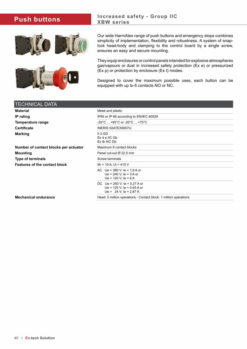
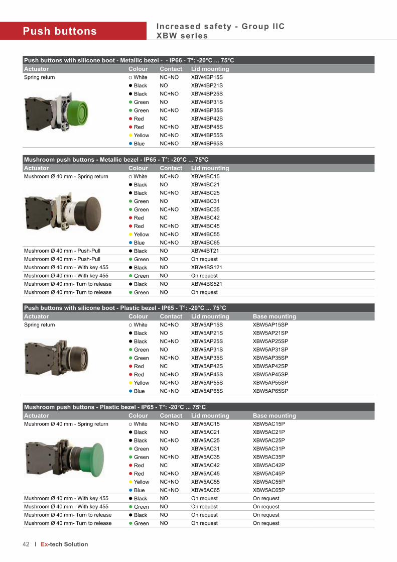
Push buttonsIncreased safety - Group I ICXBW series
Our wide HarmAtex range of push buttons and emergency stops combines
simplicity of implementation, flexibility and robustness. A system of snap-lock head-body and clamping to the control board by a single screw,
ensures an easy and secure mounting.
They equip enclosures or control panels intended for explosive atmospheres
gas/vapours or dust in increased safety protection (Ex e) or pressurized
(Ex p) or protection by enclosure (Ex t) modes.
Designed to cover the maximum possible uses, each button can be
equipped with up to 6 contacts NO or NC.
TECHNICAL DATA
Material Metal and plastic
IP rating IP65 or IP 66 according to EN/IEC 60529
Temperature range -20°C ... +65°C or -20°C ... +75°C
Certificate INERIS 02ATEX9007U
Marking II 2 GD
Ex d e IIC Gb
Ex tb IIIC Db
Number of contact blocks per actuator Maximum 6 contact blocks
Mounting Panel cut-out Ø 22,5 mm
Type of terminals Screw terminals
Features of the contact block Ith = 10 A; Ui = 415 V
AC Ue = 380 V; Ie = 1,9 A or Ue = 240 V; Ie = 3 A or Ue = 120 V; Ie = 6 ADC Ue = 250 V; Ie = 0,27 A or Ue = 125 V; Ie = 0,55 A or Ue = 24 V; Ie = 2,87 A
Mechanical endurance Head: 5 million operations - Contact block: 1 million operations
40 Ex-tech Solution

simplicity of implementation, flexibility and robustness. A system of snap-Push buttons - Metallic bezel - IP66 - T°: -20°C ... 75°C
Type of actuator Colour Contact Lid mounting
Spring return, flush actuator White NC+NO XBW4BA15l Black NO XBW4BA21l Black NC+NO XBW4BA25l Green NO XBW4BA31l Green NC+NO XBW4BA35l Red NC XBW4BA42l Red NC+NO XBW4BA45l Yellow NC+NO XBW4BA55l Blue NC+NO XBW4BA65
Spring return, projecting actuator White NC+NO XBW4BL15l Black NO XBW4BL21l Black NC+NO XBW4BL25l Green NO XBW4BL31l Green NC+NO XBW4BL35l Red NC XBW4BL42l Red NC+NO XBW4BL45l Yellow NC+NO XBW4BL55l Blue NC+NO XBW4BL65
Push buttons - Metallic bezel - IP66 - T°: -20°C ... 75°C
Type of actuator Colour Contact Lid mounting
“Push-push” to release, flush actuator White NC+NO XBW4BH015l Black NO XBW4BH021l Black NC+NO XBW4BH025l Green NO XBW4BH031l Green NC+NO XBW4BH035l Red NC XBW4BH042l Red NC+NO XBW4BH045l Yellow NC+NO XBW4BH055l Blue NC+NO XBW4BH065
“Push-push” to release, projecting actuator White NC+NO XBW4BH15l Black NO XBW4BH21l Black NC+NO XBW4BH25l Green NO XBW4BH31l Green NC+NO XBW4BH35l Red NC XBW4BH42l Yellow NC+NO XBW4BH55l Blue NC+NO XBW4BH65
41 Ex-tech Solution
Push buttonsIncreased safety - Group I ICXBW series
Push buttons with silicone boot - Metallic bezel - - IP66 - T°: -20°C ... 75°C
Actuator Colour Contact Lid mounting
Spring return White NC+NO XBW4BP15Sl Black NO XBW4BP21Sl Black NC+NO XBW4BP25Sl Green NO XBW4BP31Sl Green NC+NO XBW4BP35Sl Red NC XBW4BP42Sl Red NC+NO XBW4BP45Sl Yellow NC+NO XBW4BP55Sl Blue NC+NO XBW4BP65S
Mushroom push buttons - Metallic bezel - IP65 - T°: -20°C ... 75°C
Actuator Colour Contact Lid mounting
Mushroom Ø 40 mm - Spring return White NC+NO XBW4BC15l Black NO XBW4BC21l Black NC+NO XBW4BC25l Green NO XBW4BC31l Green NC+NO XBW4BC35l Red NC XBW4BC42l Red NC+NO XBW4BC45l Yellow NC+NO XBW4BC55l Blue NC+NO XBW4BC65
Mushroom Ø 40 mm - Push-Pull l Black NO XBW4BT21Mushroom Ø 40 mm - Push-Pull l Green NO On request
Mushroom Ø 40 mm - With key 455 l Black NO XBW4BS121Mushroom Ø 40 mm - With key 455 l Green NO On request
Mushroom Ø 40 mm- Turn to release l Black NO XBW4BS521Mushroom Ø 40 mm- Turn to release l Green NO On request
Push buttons with silicone boot - Plastic bezel - IP65 - T°: -20°C ... 75°C
Actuator Colour Contact Lid mounting Base mounting
Spring return White NC+NO XBW5AP15S XBW5AP15SPl Black NO XBW5AP21S XBW5AP21SPl Black NC+NO XBW5AP25S XBW5AP25SPl Green NO XBW5AP31S XBW5AP31SPl Green NC+NO XBW5AP35S XBW5AP35SPl Red NC XBW5AP42S XBW5AP42SPl Red NC+NO XBW5AP45S XBW5AP45SPl Yellow NC+NO XBW5AP55S XBW5AP55SPl Blue NC+NO XBW5AP65S XBW5AP65SP
Mushroom push buttons - Plastic bezel - IP65 - T°: -20°C ... 75°C
Actuator Colour Contact Lid mounting Base mounting
Mushroom Ø 40 mm - Spring return White NC+NO XBW5AC15 XBW5AC15Pl Black NO XBW5AC21 XBW5AC21Pl Black NC+NO XBW5AC25 XBW5AC25Pl Green NO XBW5AC31 XBW5AC31Pl Green NC+NO XBW5AC35 XBW5AC35Pl Red NC XBW5AC42 XBW5AC42Pl Red NC+NO XBW5AC45 XBW5AC45Pl Yellow NC+NO XBW5AC55 XBW5AC55Pl Blue NC+NO XBW5AC65 XBW5AC65P
Mushroom Ø 40 mm - With key 455 l Black NO On request On request
Mushroom Ø 40 mm - With key 455 l Green NO On request On request
Mushroom Ø 40 mm- Turn to release l Black NO On request On request
Mushroom Ø 40 mm- Turn to release l Green NO On request On request
42 Ex-tech Solution

Emergency stop mushroom - Snap action - Ø 40 mm - Metallic bezel - IP65 - T°: -20°C ... 65°C
Type of actuator Colour Contact Lid mounting
Push-pull l Red NC XBW4BT842l Red NC + NO XBW4BT845
With key 455 l Red NC XBW4BS9442l Red NC + NO XBW4BS9445
Turn to release l Red NC XBW4BS8442l Red NC + NO XBW4BS8445
Emergency stop mushroom - Snap action - Ø 40 mm - Plastic bezel - IP65 - T°: -20°C ... 65°C
Type of actuator Colour Contact Lid mounting Base mounting
With key 455 l Red NC XBW5AS9442 XBW5AS9442Pl Red NC + NO XBW5AS9445 XBW5AS9445P
Turn to release l Red NC XBW5AS8442 XBW5AS8442Pl Red NC + NO XBW5AS8445 XBW5AS8445P
43 Ex-tech Solution

95
8
38
XBW4BA.. or BH..
58
13
.5
38
XBW4BA.. or BH0..
95
83
8
38
Push button with 2 rows of contacts
10
Push button with 1 contact
30
96
Push button with 2 rows of 3 contacts
14
58
38
29.5
XBW4BP.. or AP...
38
.55
8
38
Ø 40
XBW4BC.. or AC... orBT... or BS
58
61
.5
38
.5
38
XBW4BS1..
10
Push button with 1 contact
30
Push button with 1 rows of 3 contacts
Push buttonsIncreased safety - Group I ICXBW series
44 Ex-tech Solution

Accessories
Function Product code For use with Colour Function Product code For use with
Metal guard padlockable ZBZ1604 XBW4BT84XBW4BS84XBW4BS94
l Red Long handle padlockable On request 2 to 3 positions selector switches. For more information ask to our front line office
Padlockable flap ZB4BZ62 All push buttons XBW4BA
l Black Blind plug for push button XAWZ3 Instead of push buttons
ZB4B64 l Red
Push button with 6 contact blocks
45 Ex-tech Solution
Additional contact blocks
Features of the contact block
Temperature range -50°C ... +75°C Electrical features Ith = 10 A; Ui = 415 VCertificate INERIS 02ATEX9007U AC Ue = 380 V; Ie = 1,9 A or
IECEx INE 13.0063U Ue = 240 V; Ie = 3 A orMarking II 2 G Ue = 120 V; Ie = 6 A
Ex d e IIC Gb DC Ue = 250 V; Ie = 0,27 A or Ue = 125 V; Ie = 0,55 A or Ue = 24 V; Ie = 2,87 A
Product code Description Product code Description
ZBWE101 NO contact block for lid mounting ZBWZ101 NO contact with metal fixing device for lid mounting ZBWE102 NC contact block for lid mounting ZBWZ102 NC contact with metal fixing device for lid mountingZBWE1111 NO contact block for base mounting ZBWZ1010 NO contact with plastic fixing device for lid mountingZBWE1121 NC contact block for base mounting ZBWZ1020 NC contact with plastic fixing device for mounting on lid
ZBWE101 or 102 ZBWE1111 or 1121 ZBWZ1010 or 1020ZBWZ101 or 102

Selector switchesIncreased safety - Group I ICXBW series
Our wide HarmAtex range of selector switches with standard or long handle
or wheel handle or key combines simplicity of implementation, flexibility and robustness. A system of snap-lock head-body and clamping to the
control board by a single screw, ensures an easy and secure mounting..
They equip enclosures or control panels intended for explosive atmospheres
gas/vapours or dust in increased safety protection (Ex e) or pressurized
(Ex p) or protection by enclosure (Ex t) modes.
Designed to cover the maximum possible uses, each button can be
equipped with up to 6 contacts NO or NC.
TECHNICAL DATA
Material Metal and plastic
IP rating IP65 or IP66 according to EN/IEC 60529
Temperature range -20°C ... +75°C
Certificate INERIS 02ATEX9007U
Marking II 2 GD
Ex d e IIC Gb
Ex tb IIIC Db
Number of contact blocks per actuator Maximum 6 contact blocks
Mounting Panel cut-out Ø 22,5 mm
Type of terminals Screw terminals
Features of the contact block Ith = 10 A; Ui = 415 V
AC Ue = 380 V; Ie = 1,9 A or Ue = 240 V; Ie = 3 A or Ue = 120 V; Ie = 6 ADC Ue = 250 V; Ie = 0,27 A or Ue = 125 V; Ie = 0,55 A or Ue = 24 V; Ie = 2,87 A
Mechanical endurance Head: 5 million operations - Contact block: 1 million operations
46 Ex-tech Solution
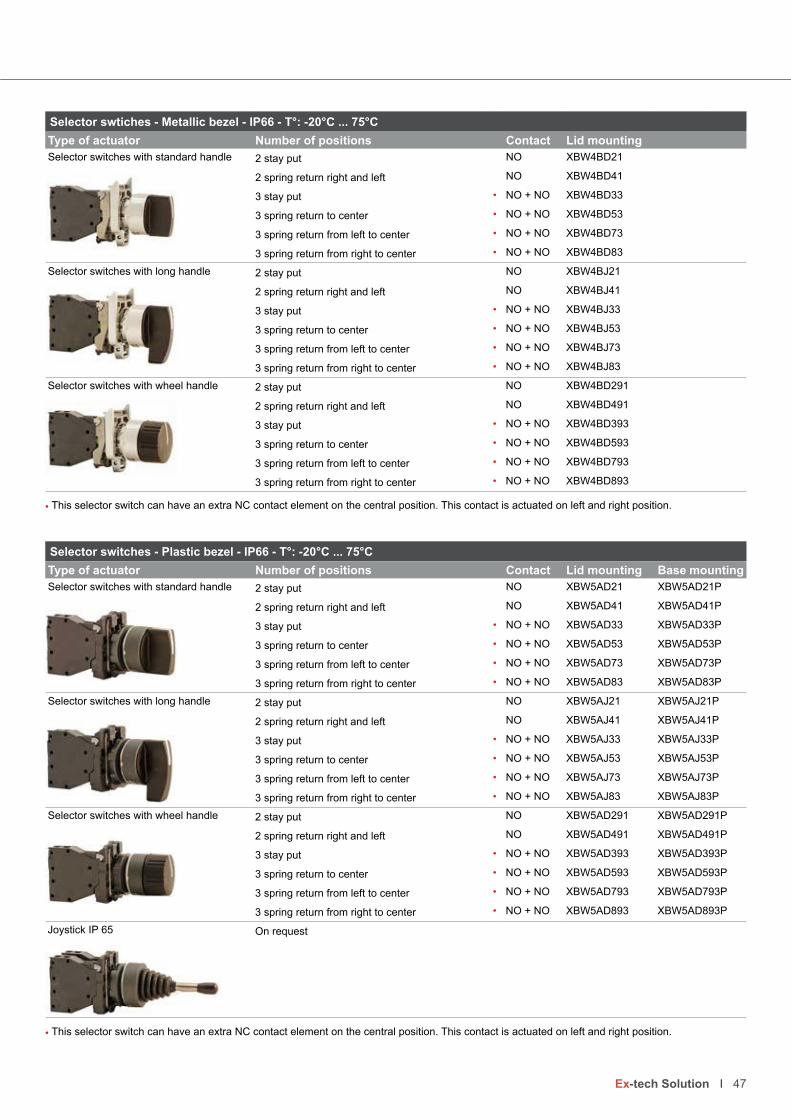
or wheel handle or key combines simplicity of implementation, flexibility Selector swtiches - Metallic bezel - IP66 - T°: -20°C ... 75°C
Type of actuator Number of positions Contact Lid mounting
Selector switches with standard handle 2 stay put NO XBW4BD21
2 spring return right and left NO XBW4BD41
3 stay put • NO + NO XBW4BD33
3 spring return to center • NO + NO XBW4BD53
3 spring return from left to center • NO + NO XBW4BD73
3 spring return from right to center • NO + NO XBW4BD83
Selector switches with long handle 2 stay put NO XBW4BJ21
2 spring return right and left NO XBW4BJ41
3 stay put • NO + NO XBW4BJ33
3 spring return to center • NO + NO XBW4BJ53
3 spring return from left to center • NO + NO XBW4BJ73
3 spring return from right to center • NO + NO XBW4BJ83
Selector switches with wheel handle 2 stay put NO XBW4BD291
2 spring return right and left NO XBW4BD491
3 stay put • NO + NO XBW4BD393
3 spring return to center • NO + NO XBW4BD593
3 spring return from left to center • NO + NO XBW4BD793
3 spring return from right to center • NO + NO XBW4BD893
• This selector switch can have an extra NC contact element on the central position. This contact is actuated on left and right position.
47 Ex-tech Solution
Selector switches - Plastic bezel - IP66 - T°: -20°C ... 75°C
Type of actuator Number of positions Contact Lid mounting Base mounting
Selector switches with standard handle 2 stay put NO XBW5AD21 XBW5AD21P
2 spring return right and left NO XBW5AD41 XBW5AD41P
3 stay put • NO + NO XBW5AD33 XBW5AD33P
3 spring return to center • NO + NO XBW5AD53 XBW5AD53P
3 spring return from left to center • NO + NO XBW5AD73 XBW5AD73P
3 spring return from right to center • NO + NO XBW5AD83 XBW5AD83P
Selector switches with long handle 2 stay put NO XBW5AJ21 XBW5AJ21P
2 spring return right and left NO XBW5AJ41 XBW5AJ41P
3 stay put • NO + NO XBW5AJ33 XBW5AJ33P
3 spring return to center • NO + NO XBW5AJ53 XBW5AJ53P
3 spring return from left to center • NO + NO XBW5AJ73 XBW5AJ73P
3 spring return from right to center • NO + NO XBW5AJ83 XBW5AJ83P
Selector switches with wheel handle 2 stay put NO XBW5AD291 XBW5AD291P
2 spring return right and left NO XBW5AD491 XBW5AD491P
3 stay put • NO + NO XBW5AD393 XBW5AD393P
3 spring return to center • NO + NO XBW5AD593 XBW5AD593P
3 spring return from left to center • NO + NO XBW5AD793 XBW5AD793P
3 spring return from right to center • NO + NO XBW5AD893 XBW5AD893P
Joystick IP 65 On request
• This selector switch can have an extra NC contact element on the central position. This contact is actuated on left and right position.

Selector switches - Metallic bezel - IP66 - T°: -20°C ... 75°C
Type of actuator Number of positions Contact Lid mounting
Selector switches with key 455 2 stay put key withdrawal in left position NO XBW4BG212 stay put key withdrawal in both position NO XBW4BG412 spring return from right to left • NO XBW4BG613 stay put, key withdrawal in 3 positions • NO + NO XBW4BG033 stay put, key withdrawal in center position • NO + NO XBW4BG333 stay put, key withdrawal in left or right position • NO + NO XBW4BG533 stay put, key withdrawal in left position NO + NO XBW4BG933 stay put, key withdrawal in right position NO + NO XBW4BG0933 spring return from left to center • NO + NO XBW4BG133 spring return to center • NO + NO XBW4BG733 spring return from right to center, keywithdrawal in center position
• NO + NO XBW4BG83
3 spring return from right to center, keywithdrawal in left position
• NO + NO XBW4BG083
• This selector switch can have an extra NC contact element on the central position. This contact is actuated on left and right position.
Selector switchesIncreased safety - Group I ICXBW series
Selector switches - Plastic bezel - IP65 - T°: -20°C ... 75°C
Type of actuator Number of positions Contact Lid mounting Base mounting
Selector switches with key 455 2 stay put key withdrawal in left position NO XBW5AG21 (1) XBW5AG21P (1)2 stay put key withdrawal in both position NO XBW5AG41 (1) XBW5AG41P (1)2 spring return from right to left NO XBW5AG61 (1) XBW5AG61P (1)3 stay put, key withdrawal in 3 positions • NO + NO XBW5AG03 (1) XBW5AG03P (1)3 stay put, key withdrawal in center position • NO + NO XBW5AG33 (1) XBW5AG33P (1)3 stay put, key withdrawal in left or right position • NO + NO XBW5AG53 (1) XBW5AG53P (1)3 stay put, key withdrawal in left position • NO + NO XBW5AG93 (1) XBW5AG93P (1)3 stay put, key withdrawal in right position • NO + NO XBW5AG093 (1) XBW5AG093P (1)3 spring return from left to center • NO + NO XBW5AG13 (1) XBW5AG13P (1)3 spring return to center • NO + NO XBW5AG73 (1) XBW5AG73P (1)3 spring return from right to center, keywithdrawal in center position
• NO + NO XBW5AG83 (1) XBW5AG83P (1)
3 spring return from right to center, keywithdrawal in left position
• NO + NO XBW5AG083 (1) XBW5AG083P (1)
• This selector switch can have an extra NC contact element on the central position. This contact is actuated on left and right position.
48 Ex-tech Solution

Selector switch with 6 contact blocks
49 Ex-tech Solution
Additional contact blocks
Features of the contact block
Temperature range -50°C ... +75°C Electrical features Ith = 10 A; Ui = 415 VCertificate INERIS 02ATEX9007U AC Ue = 380 V; Ie = 1,9 A or
IECEx INE 13.0063U Ue = 240 V; Ie = 3 A orMarking II 2 G Ue = 120 V; Ie = 6 A
Ex d e IIC Gb DC Ue = 250 V; Ie = 0,27 A or Ue = 125 V; Ie = 0,55 A or Ue = 24 V; Ie = 2,87 A
Product code Description Product code Description
ZBWE101 NO contact block for lid mounting ZBWZ101 NO contact with metal fixing device for lid mounting ZBWE102 NC contact block for lid mounting ZBWZ102 NC contact with metal fixing device for lid mountingZBWE1111 NO contact block for base mounting ZBWZ1010 NO contact with plastic fixing device for lid mountingZBWE1121 NC contact block for base mounting ZBWZ1020 NC contact with plastic fixing device for mounting on lid
27
58
38
XBW4BD.. or 5AD..
38.5
58
27
38
XBW4BJ.. or 5AJ..
26
58
38
XBW4BD.9. or 5AD.9.
29
52
58
38
XBW4BG.. or 5AG..
66
58
38
Joystick
ZBWE101 or 102 ZBWE1111 or 1121 ZBWZ1010 or 1020ZBWZ101 or 102
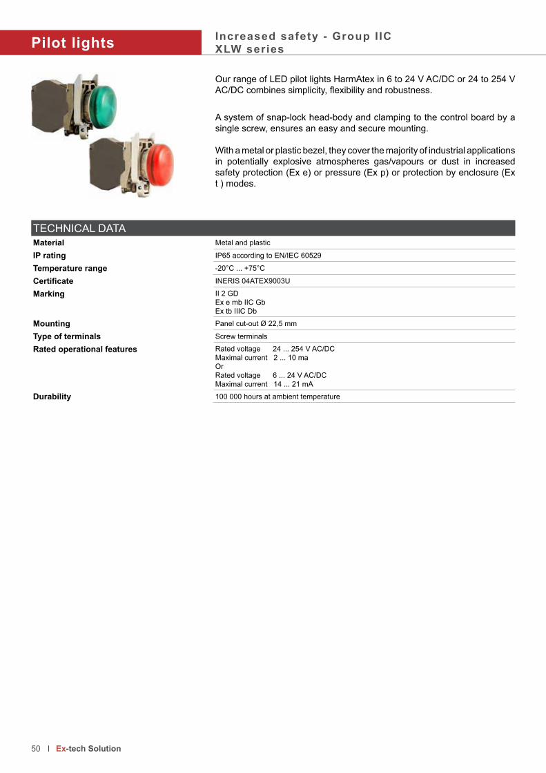
Pilot lightsIncreased safety - Group I ICXLW series
Our range of LED pilot lights HarmAtex in 6 to 24 V AC/DC or 24 to 254 V
AC/DC combines simplicity, flexibility and robustness.
A system of snap-lock head-body and clamping to the control board by a
single screw, ensures an easy and secure mounting.
With a metal or plastic bezel, they cover the majority of industrial applications
in potentially explosive atmospheres gas/vapours or dust in increased
safety protection (Ex e) or pressure (Ex p) or protection by enclosure (Ex
t ) modes.
TECHNICAL DATA
Material Metal and plastic
IP rating IP65 according to EN/IEC 60529
Temperature range -20°C ... +75°C
Certificate INERIS 04ATEX9003U
Marking II 2 GD
Ex e mb IIC Gb
Ex tb IIIC Db
Mounting Panel cut-out Ø 22,5 mm
Type of terminals Screw terminals
Rated operational features Rated voltage 24 ... 254 V AC/DC
Maximal current 2 ... 10 ma
Or
Rated voltage 6 ... 24 V AC/DC
Maximal current 14 ... 21 mA
Durability 100 000 hours at ambient temperature
50 Ex-tech Solution

AC/DC combines simplicity, flexibility and robustness.Complete LED Pilot light - 24 to 254 V AC/DC Metallic bezel Plastic bezel
Type Colour Lid mounting Base mounting Lid mounting Base mounting
Pilot light, multi-voltage and multi-current
Lid mounting
White XLW4BV013 - XLW5AV013 XLW5AV013P
l Green XLW4BV033 - XLW5AV033 XLW5AV033P
l Red XLW4BV043 - XLW5AV043 XLW5AV043P
l Yellow XLW4BV053 - XLW5AV053 XLW5AV053P
l Blue XLW4BV063 - XLW5AV063 XLW5AV063P
11
58
38
Complete LED Pilot light - 6 to 24 V AC/DC Metallic bezel Plastic bezel
Type Colour Lid mounting Base mounting Lid mounting Base mounting
Pilot light, multi-voltage and multi-current
Lid mounting
White XLW4BV013B - XLW5AV013B XLW5AV013PB
l Green XLW4BV033B - XLW5AV033B XLW5AV033PB
l Red XLW4BV043B - XLW5AV043B XLW5AV043PB
l Yellow XLW4BV053B - XLW5AV053B XLW5AV053PB
l Blue XLW4BV063B - XLW5AV063B XLW5AV063PB
LED Signalling element FOR base mounting
Type Colour Codes for 24 to 254 V AC/DC Codes for 6 to 24 V AC/DC
White ZBWL1 (1) ZBWL1B (1)
l Green ZBWL3 (1) ZBWL3B (1)
l Red ZBWL1 (1) ZBWL1B (1)
l Yellow ZBWL1 (1) ZBWL1B (1)
l Blue ZBWL1 (1) ZBWL1B (1)
(1) If the colour of the lens of the pilot light is GREEN please select the product code ZBWL1 or ZBWL3B depending on the voltage used. For any
other colour of lens select the product code ZBWL1 or ZBWL1B
LED Signalling element FOR lid mounting
Type Colour Codes for 24 to 254 V AC/DC Codes for 6 to 24 V AC/DC
White ZBWV1 (1) ZBWV1B (1)
l Green ZBWV3 (1) ZBWV3B (1)
l Red ZBWV1 (1) ZBWV1B (1)
l Yellow ZBWV1 (1) ZBWV1B (1)
l Blue ZBWV1 (1) ZBWV1B (1)
(1) If the colour of the lens of the pilot light is GREEN please select the product code ZBWV1 or ZBWV3B depending on the voltage used. For any
other colour of lens select the product code ZBWV1 or ZBWV1B
51 Ex-tech Solution
Base mounting

Illuminated buttonsIncreased safety - Group I ICXLW series
The illuminated push buttons HarmAtex is very versatile. It combines:
• pilot lights in 6 to 24 V AC/DC or 24 V to 254 V AC/DC• up to 4 contact blocks can be implement by push button• optional silicone boots can be provided
They cover the majority of industrial applications in potentially explosive
atmospheres gas/vapours or dust in increased safety protection (Ex e) or
pressure (Ex p) or protection by enclosure (Ex t ) modes by having the
highest level of protection.
TECHNICAL DATA
Material Metal and plastic
IP rating IP65 according to EN/IEC 60529
Temperature range -20°C ... +75°C
Certificate INERIS 04ATEX9003U, INERIS 02ATEX9007U
Marking II 2 GD
Ex e mb IIC Gb
Ex d e mb IIC Gb
Ex tb IIIC Db
Number of contact blocks per actuator Maximum 4 contact blocks
Mounting Panel cut-out Ø 22,5 mm
Type of terminals Screw terminals
LED pilot light Rated voltage 24 V ... 254 V AC/DC
Maximal current 2 mA ... 10 mA
Or
Rated voltage 6 V ... 24 V AC/DC
Maximal current 14 mA ... 21 mA
Features of the contact block Ith = 10 A; Ui = 415 V
AC Ue = 380 V; Ie = 1,9 A or Ue = 240 V; Ie = 3 A or Ue = 120 V; Ie = 6 ADC Ue = 250 V; Ie = 0,27 A or Ue = 125 V; Ie = 0,55 A or Ue = 24 V; Ie = 2,87 A
Mechanical endurance Head: 5 million operations - Contact block: 1 million operations
52 Ex-tech Solution

• • •
14
58
38
Illuminated push buttons 24 V ... 254 V AC/DC - Metallic bezel
Type of actuator Colour Contact Lid mounting
Illuminated push button, spring return White NO XLW4BP1831
l Green NO XLW4BP3831
l Red NC XLW4BP4832
l Yellow NO XLW4BP5831
l Blue NO XLW4BP6831
Illuminated push buttons 6 V ... 24 V AC/DC - Metallic bezel
Type of actuator Colour Contact Lid mounting
Illuminated push button, spring return White NO XLW4BP1831B
l Green NO XLW4BP3831B
l Red NC XLW4BP4832B
l Yellow NO XLW4BP5831B
l Blue NO XLW4BP6831B
53 Ex-tech Solution
Additional contact blocks
Features of the contact block
Temperature range -50°C ... +75°C Electrical features Ith = 10 A; Ui = 415 VCertificate INERIS 02ATEX9007U AC Ue = 380 V; Ie = 1,9 A or
IECEx INE 13.0063U Ue = 240 V; Ie = 3 A orMarking II 2 G Ue = 120 V; Ie = 6 A
Ex d e IIC Gb DC Ue = 250 V; Ie = 0,27 A or Ue = 125 V; Ie = 0,55 A or Ue = 24 V; Ie = 2,87 A
Type Product code Description
ZBWE101 NO
ZBWE102 NC
LED Signalling element FOR lid mounting
Type Colour Codes for 24 to 254 V AC/DC Codes for 6 to 24 V AC/DC
White ZBWV1 (1) ZBWV1B (1)
l Green ZBWV3 (1) ZBWV3B (1)
l Red ZBWV1 (1) ZBWV1B (1)
l Yellow ZBWV1 (1) ZBWV1B (1)
l Blue ZBWV1 (1) ZBWV1B (1)
(1) If the colour of the lens of the pilot light is GREEN please select the product code ZBWV1 or ZBWV3B depending on the voltage used. For any
other colour of lens, select the product code ZBWV1 or ZBWV1B
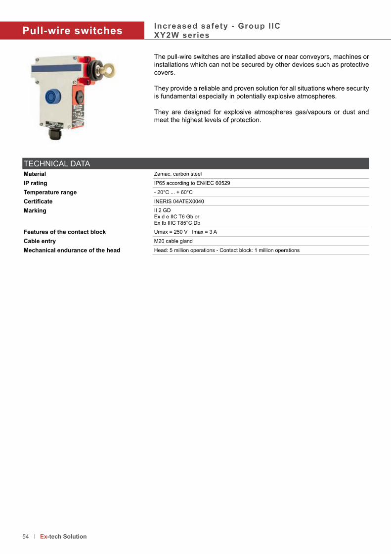
Pull-wire switchesIncreased safety - Group I ICXY2W series
The pull-wire switches are installed above or near conveyors, machines or
installations which can not be secured by other devices such as protective
covers.
They provide a reliable and proven solution for all situations where security
is fundamental especially in potentially explosive atmospheres.
They are designed for explosive atmospheres gas/vapours or dust and
meet the highest levels of protection.
TECHNICAL DATA
Material Zamac, carbon steel
IP rating IP65 according to EN/IEC 60529
Temperature range - 20°C ... + 60°C
Certificate INERIS 04ATEX0040
Marking II 2 GD
Ex d e IIC T6 Gb or
Ex tb IIIC T85°C Db
Features of the contact block Umax = 250 V Imax = 3 A
Cable entry M20 cable gland
Mechanical endurance of the head Head: 5 million operations - Contact block: 1 million operations
54 Ex-tech Solution

Product code Control unit type Operating anchoring cable point Contact
XY2WCE2A250 Reset by booted push button To left 1 x NC + NO
XY2WCE2A270 Reset by booted push button To left 2 x NC + NC
XY2WCE1A250 Reset by booted push button To right 1 x NC + NO
XY2WCE1A270 Reset by booted push button To right 2 x NC + NC
XY2WCE2A450 Reset by key release push button - Key 421 To left 1 x NC + NO
XY2WCE2A470 Reset by key release push button - Key 421 To left 2 x NC + NC
XY2WCE1A450 Reset by key release push button - Key 421 To right 1 x NC + NO
XY2WCE1A470 Reset by key release push button - Key 421 To right 2 x NC + NC
55 Ex-tech Solution
Accessories Product code Description
XY2WCZ705 Cable pulley support
XY2WCZ708 Pulley for Ø 5 mm cable max.
XY2WCZ701 Cable end protector for cable Ø 3,2 mm
XY2WCZ704 Cable end protector for cable Ø 5 mm
XY2WCZ602 Swivelling cable support
XY2WCZ702 End spring
M85355
Ø 9
229
Ø 6
Elongated holes
63
120
6
195
12
14
2
105
52
23
2582
30
44

Foot SwitchesIncreased safety - Group I ICXPEW series
The foot switch XPEW is a range of foot switches for explosive atmospheres leaving to the operator complete freedom of movement.
They are designed for explosive atmospheres gas/vapours or dust and
meet the highest levels of protection.
56 Ex-tech Solution
TECHNICAL DATA
Material Zamac, carbon steel
IP rating IP65 according to EN/IEC 60529
Temperature range - 20°C ... + 60°C
Certificate INERIS 04ATEX0042
Marking II 2 GD
Ex d e IIC T6 Gb or
Ex tb IIIC T85°C Db
Features of the contact block Umax = 250 V Imax = 3 A
Cable entry M20 cable gland
Mechanical endurance Actuator: 5 million operations - Contact block: 1 million operations
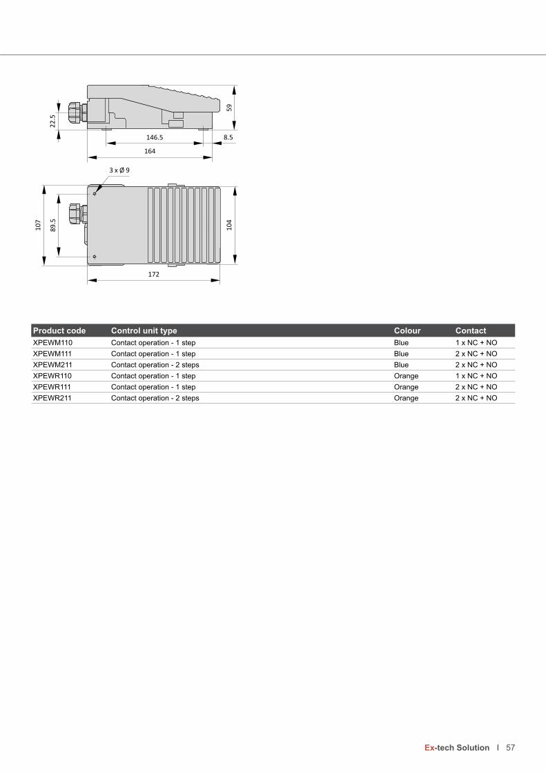
The foot switch XPEW is a range of foot switches for explosive atmospheres
Product code Control unit type Colour Contact
XPEWM110 Contact operation - 1 step Blue 1 x NC + NO
XPEWM111 Contact operation - 1 step Blue 2 x NC + NO
XPEWM211 Contact operation - 2 steps Blue 2 x NC + NO
XPEWR110 Contact operation - 1 step Orange 1 x NC + NO
XPEWR111 Contact operation - 1 step Orange 2 x NC + NO
XPEWR211 Contact operation - 2 steps Orange 2 x NC + NO
3 x Ø 9
146.5
164
8.5
22
.58
9.5
10
7
172
10
45
9
57 Ex-tech Solution
58 Ex-tech Solution

Motor Starters - Motor Isolators
Content Page
Motor starters - Flameproof
Motor starters AC1WD, ERSA, DE8BA series - Explosion gas group IIB 60
Motor starters DE8WH series - Explosion gas group IIC 62
Motor isolators - Increased safety
Polyester and stainless steel motor isolators DE1 series 64
59 Ex-tech Solution

Motor startersFlameproof - Group I IBAluminium - AC1WD, DE8BA and ERSA series
The robust range of 3-poles explosion-proof motor starters with thermal
relay is ideal for many applications. It is available in three versions:
• with thermal overload relay, without contactor and no fuse
• with thermal overload relay and fuses, without contactor
• with thermal overload relay, contactor and fuses
A wide range of enclosures combined with a wide range of thermal overload
relays, contactors, with or without fuses, allows customisation of the motor
starters for different applications.
Any individual solution available on request.
TECHNICAL DATA
Material Cast aluminium for AC1WD and ERSA, cast iron for DE8BA
IP rating IP65 according to EN/IEC 60529
Temperature range -20°C ... +40°C or +50°C or +60°C
Certificate INERIS 03ATEX0145 for AC1DWINERIS 03ATEX144X for DE8BAINERIS 04ATEX0009X for ERSA
Marking II 2 GD
AC1WD
Ex d IIB T6 Gb
Ex tb IIIC T85°C Db
DE8BA
Ex d IIB T6 ... T4 Gb
Ex tb IIIC T85°C ... 135°C Db
ERSA
Ex d IIB T6 ... T4 Gb
Ex tb IIIC T85°C ... 135°C
Electrical features AC1WD
Imax = 65 A; Umax = 500 V
DE8BA
Imax = 220 A; Umax = 750 V
ERSA Imax = 500 A; Umax = 1000 V
Mechanical endurance of the push buttons Head: 5 million operations - Contact block: 1 million operations
Surface treatment Painting RAL 7032 - Other colour on request
ERSAAC1WD
DE8BA
60 Ex-tech Solution
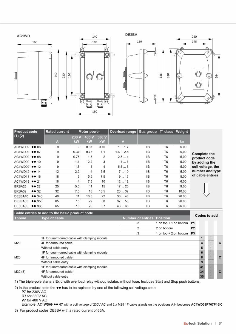
• • •
Product code(1) (2)
Rated current Motor power Overload range Gas group T° class Weight
Complete the product code by adding the coil voltage, the number and type of cable entries
230 V 400 V 500 VA kW kW kW A kg
AC1WD09 ll 06 9 - 0.37 0.75 1 ... 1.7 IIB T6 5.00
AC1WD09 ll 07 9 0.37 0.75 1.1 1.6 ... 2.5 IIB T6 5,00
AC1WD09 ll 08 9 0.75 1.5 2 2.5 ... 4 IIB T6 5,00
AC1WD09 ll 10 9 1.1 2.2 3 4 ... 6 IIB T6 5,00
AC1WD09 ll 12 9 1.8 3 4 5.5 ... 8 IIB T6 5,00
AC1WD12 ll 14 12 2.2 4 5.5 7 ... 10 IIB T6 5.00
AC1WD18 ll 16 18 3 5.5 7.5 9 ... 13 IIB T6 5.00
AC1WD18 ll 21 18 4 7.5 10 12 ... 18 IIB T6 6.00
ERSA25 ll 22 25 5.5 11 15 17 ... 25 IIB T6 9.00
ERSA32 ll 32 32 7.5 15 18.5 23 ... 32 IIB T6 10.00
DE8BA40 ll 340 40 11 18.5 22 30 ... 40 IIB T6 26.00
DE8BA65 ll 350 65 15 22 30 37 ... 50 IIB T6 26.00
DE8BA65 ll 365 65 15 25 37 48 ... 65 IIB T6 26.00
1) The triple-pole starters Ex d with overload relay without isolator, without fuse. Includes Start and Stop push buttons.
2) In the product code the ll has to be replaced by one of the following coil voltage code: P7 for 230V AC Q7 for 380V AC V7 for 400 V AC Example: AC1WD09 ll 07 with a coil voltage of 230V AC and 2 x M25 1F cable glands on the positions A,H becomes AC1WD09P707P16IC
3) For product codes DE8BA with a rated current of 65A.
Cable entries to add to the basic product codeCodes to add
Thread Type of cable Number of entries Position
2 1 on top + 1 on bottom P1
2 2 on bottom P2
3 1 on top + 2 on bottom P3
M20
1F for unarmoured cable with clamping module 1 I
C4F for armoured cable 4 I
Without cable entry 5 I
M25
1F for unarmoured cable with clamping module 6 I
C4F for armoured cable 8 I
Without cable entry 9 I
M32 (3)
1F for unarmoured cable with clamping module 31 I
C4F for armoured cable 34 I
Without cable entry 35 I
24
0
160
19
0
110
140
160
22
0
220
32
0
148
26
4
180
33
6
61 Ex-tech Solution
AC1WD DE8BA

Motor startersFlameproof - Group I ICCast iron - DE8WH series
The robust range of 3-poles explosion-proof motor starters with thermal
relay is ideal for many applications. It is available in three versions:
• with thermal overload relay, without contactor and no fuse
• with thermal overload relay and fuses, without contactor
• with thermal overload relay, contactor and fuses
A wide range of enclosures combined with a wide range of thermal
overload relays, contactors, with or without fuses, allows customisation of
the motor starters for different applications. They meet the highest levels
of protection.
Any individual solution available on request.
TECHNICAL DATA
Material Aluminium
IP rating IP65 according to EN/IEC 60529
Temperature range -20°C ... +40°C or +50°C or +60°C
Certificate IINERIS 03ATEX0121X
Marking II 2 GD
Ex d IIC T6 ... T4 Gb
Electrical features Imax = 65 A; Umax = 500 V AC
Mechanical endurance of the push buttons Head: 5 million operations - Contact block: 1 million operations
Surface treatment Painting RAL 7032 - Other colour on request
62 Ex-tech Solution

• • •
1) The triple-pole starters Ex d with overload relay without isolator, without fuse. Includes Start and Stop push buttons.
2) In the product code the ll has to be replaced by one of the following coil voltage code: P7 for 230V AC Q7 for 380V AC V7 for 400 V AC Example: DE8WH09 ll 07 with a coil voltage of 230V AC and 2 x M25 1F cable glands on the positions A,H becomes DE8WH09P707P16IC
3) For product codes DE8WH with a rated current of 65A.
Cable entries to add to the basic product codeCodes to add
Thread Type of cable Number of entries Position
2 1 on top + 1 on bottom P1
2 2 on bottom P2
3 1 on top + 2 on bottom P3
M20
1F for unarmoured cable with clamping module 1 I
C4F for armoured cable 4 I
Without cable entry 5 I
M25
1F for unarmoured cable with clamping module 6 I
C4F for armoured cable 8 I
Without cable entry 9 I
M32 (3)
1F for unarmoured cable with clamping module 31 I
C4F for armoured cable 34 I
Without cable entry 35 I
Product code(1) (2)
Rated current Motor power Overload range Gas group T° class Weight
Complete the product code by adding the coil voltage, the number and type of cable entries
230 V 400 V 500 VA kW kW kW A kg
DE8WH09 ll 06 9 - 0.37 0.75 1 ... 1.7 IIC T3 12,00
DE8WH09 ll 07 9 0.37 0.75 1.1 1.6 ... 2.5 IIC T3 12,00
DE8WH09 ll 08 9 0.75 1.5 2 2.5 ... 4 IIC T3 12,00
DE8WH09 ll 10 9 1.1 2.2 3 4 ... 6 IIC T3 12,00
DE8WH09 ll 12 9 1.8 3 4 5.5 ... 8 IIC T3 12,00
DE8WH12 ll 14 12 2.2 4 5.5 7 ... 10 IIC T3 12,00
DE8WH18 ll 16 18 3 5.5 7.5 9 ... 13 IIC T3 12,00
DE8WH18 ll 21 18 4 7.5 10 12 ... 18 IIC T3 12,00
DE8WH25 ll 22 25 5.5 11 15 17 ... 25 IIC T3 12,00
DE8WH32 ll 32 32 7.5 15 18.5 23 ... 32 IIC T3 12,00
DE8WH40 ll 340 40 11 18.5 22 30 ... 40 IIC T3 12,00
DE8WH65 ll 350 65 15 22 30 37 ... 50 IIC T3 12,00
DE8WH65 ll 365 65 15 25 37 48 ... 65 IIC T3 12,00
260
26
0
116 Ø 9 x 12
28
6
210
12
63 Ex-tech Solution

Safety switchesIncreased safety - Group I ICDE1 series
The safety switches are made of polyester (GRP) or stainless steel AISI
316L.
They provide isolation during maintenance or repair of machines in every
industrial application in hazardous areas.
TECHNICAL DATA
Material GRP or Stainless steel AISI 316L
IP rating IP66 according to EN/IEC 60529
Temperature range -20°C/-50°c ... +40°C/+60°C
Certificate INERIS
Marking II 2 GDEx d e IIC T4/T5 GbEx tb IIIC T80°C Db IP66
Polarity 2P or 3/4 poles
Electrical features Category AC22A Rated current 20A 25A 32A 40A 63ARated voltage 690V 690V 690V 690V 690V
Category AC23A Rated current 20A 25A 32A 40A 63ARated voltage - - - 690V 690VRated voltage 500V 500V 500V 500V 500V
Category AC3 Rated current 20A 25A 32A 40A 63ARated voltage 500V 500V 500V - -
Accessories on request Earth-stud
Breath valves
Auxiliary contacts
Ambient temperature of -50°C ... +55°C or +60°C
64 Ex-tech Solution

65 Ex-tech Solution
Enclosure in GRP Enclosure in stainless steel
P
H
fixi
ng
CØ 6.5
Fixing holes
A
B
L
fixing
C B
A H
L
Ø 9
Fixing holes
P
Enclosure in glass-reinforced polyester ( GRP)General use (1)
Emergency use (2)
Number poles
Rated current
Cable entries
Dimensions T° Gas (3) T° Dust
A B C P H x L -20°C...60°C -20°C...60°C
DE1GU202 DE1EU202 2P 20A 2 x M25 160 160 91 125 110 x 140 T4 T80°C
DE1GU204 DE1EU204 3/4P 20A 2 x M25 160 160 91 125 110 x 140 T4 T80°C
DE1GU252 DE1EU252 2P 25A 2 x M25 160 160 91 125 110 x 140 T4 T80°C
DE1GU254 DE1EU254 3/4P 25A 2 x M25 160 160 91 125 110 x 140 T4 T80°C
DE1GU322 DE1EU322 2P 32A 2 x M25 160 160 91 125 110 x 140 T4 T80°C
DE1GU324 DE1EU324 3/4P 32A 2 x M32 160 160 91 125 110 x 140 T4 T80°C
DE1GU402 DE1EU402 2P 40A 2 x M32 250 255 121 155 200 x 235 T4 T80°C
DE1GU404 DE1EU404 3/4P 40A 2 x M40 250 255 121 155 200 x 235 T4 T80°C
DE1GU632 DE1EU632 2P 63A 2 x M40 250 255 121 155 200 x 235 T4 T80°C
DE1GU634 DE1EU634 3/4P 63A 2 x M50 250 255 121 155 200 x 235 T4 T80°C
1) The colour of the handle switch is black
2) The colour of t handle he switch is red and yellow
3) Temperature class T5 with an ambient temperature of +40°C ot +50°C
Enclosure in stainless steel AISI 316LGeneral use (1)
Emergency use (2)
Number poles
Rated current
Cable entries
Dimensions T° Gas (3) T° Dust
A B C P H x L -20°C...60°C -20°C...60°C
SDE1GU202 SDE1EU202 2P 20A 2 x M25 200 150 150 185 150 x 200 T4 T80°C
SDE1GU204 SDE1EU204 3/4P 20A 2 x M25 200 150 150 185 150 x 200 T4 T80°C
SDE1GU252 SDE1EU252 2P 25A 2 x M25 200 150 150 185 150 x 200 T4 T80°C
SDE1GU254 SDE1EU254 3/4P 25A 2 x M25 200 150 150 185 150 x 200 T4 T80°C
SDE1GU322 SDE1EU322 2P 32A 2 x M25 200 150 150 185 150 x 200 T4 T80°C
SDE1GU324 SDE1EU324 3/4P 32A 2 x M32 200 150 150 185 150 x 200 T4 T80°C
SDE1GU402 SDE1EU402 2P 40A 2 x M32 300 200 150 185 250 x 250 T4 T80°C
SDE1GU404 SDE1EU404 3/4P 40A 2 x M40 300 200 150 185 250 x 250 T4 T80°C
SDE1GU632 SDE1EU632 2P 63A 2 x M40 300 200 150 185 250 x 250 T4 T80°C
SDE1GU634 SDE1EU634 3/4P 63A 2 x M50 300 200 150 185 250 x 250 T4 T80°C
1) The colour of the handle switch is black
2) The colour of t handle he switch is red and yellow
3) Temperature class T5 with an ambient temperature of +40°C or +50°C
AccessoriesProduct code Description Product code Description
DE1VE Breather valve ZBWE101 (4) Auxiliary contact NO - Max. 2 contacts
DE1TT Earth-stud ZBWE102 (4) Auxiliary contact NC - Max. 2 contacts
(4) The contacts NO and NC can be mixed to fit 1NO + 1NC

66 Ex-tech Solution

67 Ex-tech Solution
Junction boxes
Content Page
Increased safety
XAWG series in glass-reinforced polyester 68
XAWF series in aluminium 70
DE1WG series in carbon steel and stainless steel 72
TNAE series in stainless steel 74
Flameproof - Explosion gas group IIB and IIC
DE8BA and XADW series - Explosion gas group IIB 76
XAEW series - Explosion gas group IIC 76
ERSA series - Large junction boxes - Explosion gas group IIB 78

Junction boxesIncreased safety - Group I ICGlass-reinforced polyester - XAWG series
The junction boxes XAWG made in glass-reinforced polyester (GRP), are ideal for environments in the presence of chemical agents, corrosion
resistant and suitable for very high and very low ambient temperatures.
The maximum number of terminals depends on the terminal section, the
ambient temperature and the required temperature class.
On request, they can also be equipped with push buttons, selector switches,
pilot lights, measurement instruments and are available in other sizes.
TECHNICAL DATA
Material Glass-reinforced polyester loaded with carbon black for antistatic protection
IP rating IP66 according to EN/IEC 60529
Temperature range -50°C ... +60°C
Certificate INERIS 03ATEX0122X
Marking II 2 GD
Ex e IIC T6 ... T5 Gb
Ex tb IIIC Db T85°C ... T100°C
Surface treatment Finishing natural black RAL 9005
Accessories on request External hinges in thermoplastic
Drain and breather valves
Fixing bracket in stainless steel AISI 316L
Earth continuity plate, internal, in zinc platted brass or copper
Earth stud in brass or stainless steel
Cable glands
68 Ex-tech Solution

The junction boxes XAWG made in glass-reinforced polyester (GRP),
DimensionsProduct code External Internal Fixing holes Weight
A B C F G P D E kg
XAWG0809 75 80 75 58 48 66 45 68 0.31
XAWG0812 75 110 75 58 78 66 45 98 0.39
XAWG0817 75 160 75 58 128 66 45 148 0.51
XAWG0820 75 190 75 58 158 66 45 178 0.56
XAWG0824 75 230 75 58 198 66 39 218 0.69
XAWG1212 120 122 90 102 104 80 82 106 0.78
XAWG1222 120 220 90 102 190 80 82 204 1.07
XAWG1616 160 160 90 142 112 80 110 140 1.20
XAWG1626 160 260 90 142 212 80 110 240 1.65
XAWG1636 160 360 90 142 312 80 110 340 2.05
XAWG1656 160 560 90 142 512 80 110 540 3.07
XAWG2526 250 255 120 230 235 110 200 235 2.56
XAWG2540 250 400 120 230 380 110 200 380 3.59
XAWG2560 250 600 120 230 580 110 200 560 5.24
XAWG4140 405 400 165 385 380 154 355 380 5.82
Number maximum of entries per sideProduct code Size Maximum of entries on the long sides Maximum of entries on the short sides
A x B x C M12 M16 M20 M25 M32 M40 M50 M63 M12 M16 M20 M25 M32 M40 M50 M63
XAWG0809 75 x 80 x 75 4 2 1 1 - - - - 2 2 - - - - - -
XAWG0812 75 x 110 x 75 6 6 3 2 1 - - - 2 2 - - - - - -
XAWG0817 75 x 160 x 75 10 10 5 3 2 - - - 2 2 - - - - - -
XAWG0820 75 x 190 x 75 14 12 6 4 3 - - - 2 2 - - - - - -
XAWG0824 75 x 230 x 75 16 12 6 4 2 - - - 2 2 - - - - - -
XAWG1212 120 x 122 x 90 6 5 2 1 1 - - - 5 5 4 1 1 - - -
XAWG1222 120 x 220 x 90 14 14 9 4 3 - - - 5 4 2 1 1 - - -
XAWG1616 160 x 160 x 90 12 8 6 3 2 1 - - 6 6 4 2 1 - - -
XAWG1626 160 x 260 x 90 26 16 12 6 4 3 - - 6 6 4 2 1 - - -
XAWG1636 160 x 360 x 90 38 22 18 9 6 4 - - 6 6 4 2 1 - - -
XAWG1656 160 x 560 x 90 58 36 28 14 8 6 - - 6 6 4 2 1 - - -
XAWG2526 250 x 255 x 120 24 18 10 8 4 3 2 2 21 15 8 6 3 2 2 1
XAWG2540 250 x 400 x 120 42 33 18 16 6 5 4 3 21 15 8 6 3 2 2 1
XAWG4140 405 x 400 x 165 70 44 27 21 12 10 4 3 65 40 24 21 10 10 4 3
H
B E G
C A
DØ I
Fixing holes
F
69 Ex-tech Solution

Junction boxesIncreased safety - Group I ICAluminium - XAWF series
The junction boxes XAWF made in aluminium are ideal for environments in the presence of chemical agents, corrosion resistant and suitable for very
high and very low ambient temperatures.
The maximum number of terminals depends on the terminal section, the
ambient temperature and the required temperature class.
On request, they can also be equipped with push buttons, selector switches,
pilot lights, measurement instruments and are available in other sizes.
TECHNICAL DATA
Material Aluminium
IP rating IP66 according to EN/IEC 60529
Temperature range -50°C ... +60°C
Certificate INERIS 03ATEX0122X
Marking II 2 GD
Ex e IIC T6 ... T4 Gb
Ex tb IIIC T85°C ... T135°C Db
Surface treatment Painting black RAL 9005
Accessories on request External hinges in thermoplastic
Drain and breather valves
Fixing bracket in stainless steel AISI 316L
Earth continuity plate, internal, in zinc platted brass or copper
Earth stud in brass or stainless steel
Cable glands
70 Ex-tech Solution
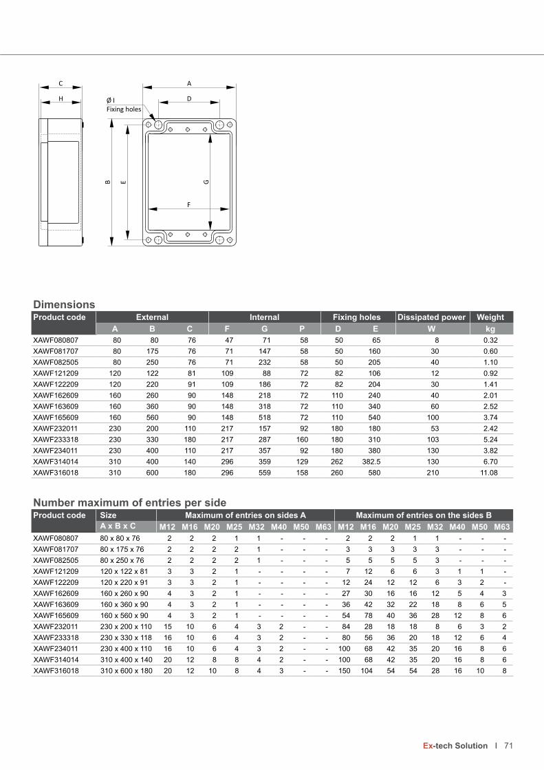
The junction boxes XAWF made in aluminium are ideal for environments in
DimensionsProduct code External Internal Fixing holes Dissipated power Weight
A B C F G P D E W kg
XAWF080807 80 80 76 47 71 58 50 65 8 0.32
XAWF081707 80 175 76 71 147 58 50 160 30 0.60
XAWF082505 80 250 76 71 232 58 50 205 40 1.10
XAWF121209 120 122 81 109 88 72 82 106 12 0.92
XAWF122209 120 220 91 109 186 72 82 204 30 1.41
XAWF162609 160 260 90 148 218 72 110 240 40 2.01
XAWF163609 160 360 90 148 318 72 110 340 60 2.52
XAWF165609 160 560 90 148 518 72 110 540 100 3.74
XAWF232011 230 200 110 217 157 92 180 180 53 2.42
XAWF233318 230 330 180 217 287 160 180 310 103 5.24
XAWF234011 230 400 110 217 357 92 180 380 130 3.82
XAWF314014 310 400 140 296 359 129 262 382.5 130 6.70
XAWF316018 310 600 180 296 559 158 260 580 210 11.08
HB E G
C A
DØ I
Fixing holes
F
71 Ex-tech Solution
Number maximum of entries per sideProduct code Size Maximum of entries on sides A Maximum of entries on the sides B
A x B x C M12 M16 M20 M25 M32 M40 M50 M63 M12 M16 M20 M25 M32 M40 M50 M63
XAWF080807 80 x 80 x 76 2 2 2 1 1 - - - 2 2 2 1 1 - - -
XAWF081707 80 x 175 x 76 2 2 2 2 1 - - - 3 3 3 3 3 - - -
XAWF082505 80 x 250 x 76 2 2 2 2 1 - - - 5 5 5 5 3 - - -
XAWF121209 120 x 122 x 81 3 3 2 1 - - - - 7 12 6 6 3 1 1 -
XAWF122209 120 x 220 x 91 3 3 2 1 - - - - 12 24 12 12 6 3 2 -
XAWF162609 160 x 260 x 90 4 3 2 1 - - - - 27 30 16 16 12 5 4 3
XAWF163609 160 x 360 x 90 4 3 2 1 - - - - 36 42 32 22 18 8 6 5
XAWF165609 160 x 560 x 90 4 3 2 1 - - - - 54 78 40 36 28 12 8 6
XAWF232011 230 x 200 x 110 15 10 6 4 3 2 - - 84 28 18 18 8 6 3 2
XAWF233318 230 x 330 x 118 16 10 6 4 3 2 - - 80 56 36 20 18 12 6 4
XAWF234011 230 x 400 x 110 16 10 6 4 3 2 - - 100 68 42 35 20 16 8 6
XAWF314014 310 x 400 x 140 20 12 8 8 4 2 - - 100 68 42 35 20 16 8 6
XAWF316018 310 x 600 x 180 20 12 10 8 4 3 - - 150 104 54 54 28 16 10 8

Junction boxesIncreased safety - Group I IC - Painted steelor stainless steel AISI 316L- DE1GW series
The junction boxes DEIGW are ideal for environments in the presence of
chemical agents, corrosion resistant and suitable for very high and very low
ambient temperatures.
The maximum number of terminals depends of terminals section, operating
temperature and required temperature class. They are equipped with a
mounting plate and the fixing brackets.
They can also be equipped with push buttons, selector switches, pilot
lights, measurement instruments and are available in other sizes.
TECHNICAL DATA
Material Carbon steel painted or stainless steel AISI 316L
IP rating IP65/66 according to EN/IEC 60529
Temperature range -40°C ... +60°C (T4)
-40°C ... +50°C (T5)
-40°C ... +40°C (T6)
Certificate INERIS 03ATEX0006
Marking II 2 GD
Ex e IIC T6 ... T4 Gb
Ex tb IIIC T85°C ... T135°C Db
Surface treatmentCarbon steel: painting RAL 7035, other colour on request
Stainless steel: bead blasting as standard or as option electropolished
Accessories on request External hinges
Breather valves
Earth stud in brass or stainless steel
Cover locking facilities
Gland plates
Cable glands
72 Ex-tech Solution

mounting plate and the fixing brackets.
DimensionsProduct codes carbon steel
Product codes stainless steel
External Fixing Max. dissipated power Volume Weight
A B C See drawing at Tamb = 40°C (W) (dm3) (kg)
DE1GW302020 DE1GWS302020 200 300 200 “ 30 W 12 5
DE1GW302515 DE1GWS302515 250 300 150 “ 30 W 11 5.15
DE1GW282820 DE1GWS282820 280 280 200 “ 40 W 15 7
DE1GW403020 DE1GWS403020 300 400 200 “ 50 W 24 8.6
DE1GW383820 DE1GWS383820 380 380 200 “ 50 W 29 9.3
DE1GW385720 DE1GWS385720 570 380 200 “ 65 W 43 11.2
DE1GW504025 DE1GWS504025 400 500 250 “ 90 W 50 14.1
DE1GW575720 DE1GWS575720 570 570 200 “ 105 W 65 17.9
DE1GW577627 DE1GWS577627 760 570 270 “ 140 W 117 23.9
DE1GW706030 DE1GWS706030 600 700 300 “ 180 W 126 26.1
DE1GW907030 DE1GWS907030 700 900 300 “ 240 W 189 49.8
DE1GW769527 DE1GWS769527 950 760 270 “ 240 W 195 36.7
Other sizes available on request
Number maximum of entries per sideProduct code M16 M18 M20 M25 M32 M40 M50 M63
DE1GW302020 10 10 10 8 5 3 2 -
DE1GW302515 10 10 10 8 5 3 2 -
DE1GW282820 10 10 10 8 5 3 2 -
DE1GW403020 28 24 24 18 15 8 6 2
DE1GW383820 28 24 24 18 15 8 6 2
DE1GW385720 66 50 50 45 28 18 15 6
DE1GW504025 66 50 50 45 28 18 15 6
DE1GW575720 66 50 50 45 28 18 15 6
DE1GW577627 152 112 112 75 60 40 24 15
DE1GW706030 152 112 112 75 60 40 24 15
DE1GW907030 184 133 133 90 75 48 30 21
DE1GW769527 184 133 133 90 75 48 30 21
73 Ex-tech Solution
B
B - 50
B + 50
A +
50
A -
50
C
A

Junction boxesIncreased safety - Group I ICStainless steel AISI 316L - TNAE series
The junction boxes TNAE, made in stainless steel AISI 316L, are dedicated
to hazardous areas and ideally suited to environments in the presence of
chemical agents, seawater resistant for very high and very low operating
temperatures.
The maximum number of terminals depends on the terminal section, the
ambient temperature and the required temperature class.
TECHNICAL DATA
Material Stainless steel AISI 316L
IP rating IP66/IP67 (IP68 on request) according to EN/IEC 60529
Temperature range -40ºC ... +60ºC (T4)
-40ºC ... +40ºC (T5)
Option: -50ºC ... +60ºC
Certificate DNV 10ATEX90171
Marking II 2 GD
Ex e II T5 ... T4 Gb
Ex tD A21 T85°C ... T100°C
Surface treatment Acid as standard
Accessories upon on request Breather valves
Mounting plate
Earth continuity plate, internal,
Earth stud
Gland plates
Cable glands
Electropolished treatment
74 Ex-tech Solution

DimensionsProduct code External Fixing holes Max. dissipated power Volume Weight
A B C D E at Tamb = 40°C (W) (dm3) (kg)
TNAE121009 160 120 90 150 - 6 W 1.08 1.5
TNAE151510 187 176 100 180 - 15 W 2.25 2.5
TNAE202010 200 200 100 230 160 20 W 4.00 3.0
TNAE202015 200 200 170 230 160 20 W 6.00 3.5
TNAE282815 280 280 170 310 240 30 W 11.76 5.2
TNAE302015 200 300 170 230 260 30 W 9.00 5.0
TNAE383815 380 380 170 410 340 40 W 21.66 8.1
TNAE384515 450 380 170 480 340 50 W 25.65 8.9
TNAE385715 570 380 170 600 340 65 W 32.49 10.7
TNAE575715 570 570 170 600 530 90 W 48.74 16.4
TNAE575730 570 570 320 600 530 90 W 97.47 21.4
TNAE577620 760 570 220 790 530 120 W 86.64 21.7
TNAE769520 950 760 220 980 720 200 W 144.40 32.9
Other sizes available on request
Number maximum of entries per sideProduct code M20 - 1/2” M25 - 3/4” M32 - 1” M40 - 1” 1/4 M50 - 1” 1/2 M63 - 2”
A (1) B (1) A (1) B (1) A (1) B (1) A (1) B (1) A (1) B (1) A (1) B (1)
TNAE121009 6 4 4 2 3 2 2 1 2 1 1 1
TNAE151510 6 6 4 4 3 3 2 2 2 2 1 1
TNAE202010 10 10 7 7 4 4 2 2 2 2 2 2
TNAE202015 12 12 8 8 6 6 5 5 4 4 3 3
TNAE282815 18 18 12 12 9 9 8 8 7 7 4 4
TNAE302015 21 12 14 8 10 6 9 5 8 4 5 3
TNAE383815 24 24 16 16 12 12 10 10 9 9 6 6
TNAE384515 30 24 20 16 15 12 13 10 12 9 7 6
TNAE385715 39 24 26 16 19 12 17 10 15 9 9 6
TNAE575715 39 39 26 26 19 19 17 17 15 15 9 9
TNAE575730 88 88 58 58 44 44 39 39 35 35 22 22
TNAE577620 68 52 45 34 34 26 30 23 27 20 17 13
TNAE769520 88 68 58 45 44 34 39 30 35 27 22 17
(1) A: on the long sides - B: on the short sides
75 Ex-tech Solution
TNAE from 202010TNAE 121009 and 151510
B
C E
AD
Ø 11
B
ADC
Ø 11

Junction boxesFlameproof - Group I IB or I IC - Painted steelor aluminium - DE8BA, XAWD and XAEW series
The highly robust flameproof junction boxes DE8BA, XAWD and XAWE are designed for use in every industrial environments and can be used in
the highest restrictive hazardous areas.
The maximum number of terminals depends of terminals section, operating
temperature and required temperature class. They can also be equipped
with push buttons, selector switches, pilot lights, measurement instruments.
TECHNICAL DATA
Material DE8BA: Cast iron
XADW: AluminiumXAEW: Aluminium
IP rating IP65/66 according to EN/IEC 60529
Temperature range -20°C ... +40°C or 60°C
Certificate DE8BA: INERIS 03ATEX0144XXADW: INERIS 03ATEX0145XAEW: INERIS 03ATEX0146
Marking
II 2 GD
DE8BA
Ex d IIB T6 ... T4 Gb
Ex tb IIIC T85°C ... T135°C Db
Ex d [ia] IIB T6 Gb
Ex tb IIIC T85°C Db
XADW
Ex d IIB T6 Gb
Ex tb IIIC T85°C Db
XAEW
Ex d IIC T6 Gb
Ex tb IIIC T85°C Db
Surface treatment Painting RAL 7032
Accessories upon on request Breather valves
Internal and external earth stud
Cable glands
76 Ex-tech Solution

The highly robust flameproof junction boxes DE8BA, XAWD and XAWE
DimensionsProduct code External Fixing holes Max. dissipated power Volume Weight
A B C D x E F x G at Tamb = 40°C (W) dm3 (kg)
DE8BA 180 185 185 160 196 x 144 144 x 196 50 W 2.66 13.5
DE8BA 258 258 180 158 276 x 146 231 x 191 50 W 4.30 16.0
DE8BA 278 278 218 153 306 x 174 234 x 246 50 W 4.80 22.0
DE8BA 321 320 220 180 336 x 148 264 x 220 120 W 6.55 26.0
DE8BA 322 320 220 170 336 x 148 264 x 220 120 W 5.80 24.0
DE8BA 450 452 222 186 466 x 148 394 x 220 120 W 10.40 30.0
XADW12 150 106 89 175 x 80 125 x 130 32 W 0.55 2.68
XADW13 190 106 89 215 x 80 165 x 130 32 W 0.82 3.10
XADW22 215 130 89 240 x 105 190 x 155 32 W 1.28 3.52
XAEW12 130 130 89 160 x 160 160 x 160 32 W 0.59 2.68
Number maximum of entries per sideProduct code M20 - 1/2” M25 - 3/4” M32 - 1” M50 - 1” 1/2
A (1) B (1) Total (2) A (1) B (1) Total (2) A (1) B (1) Total (2) A (1) B (1) Total (2)
DE8BA 180 5 5 20 5 5 20 4 4 16 1 1 4
DE8BA 258 8 4 24 8 4 24 6 3 18 2 1 6
DE8BA 278 8 5 26 8 5 26 5 4 18 3 1 8
DE8BA 321 - 2 4 - 2 4 - 2 4 - - -
DE8BA 322 - 5 10 - 5 10 - 3 6 - 1 2
DE8BA 450 - 5 10 - 5 10 - 3 6 - 1 1
XADW12 2 1 6 2 1 6 - - - - - -
XADW13 3 1 8 3 1 8 - - - - - -
XADW22 3 2 10 3 2 10 - - - - - -
XAEW12 2 2 8 - - - - - - - - -
(1) A: on the long sides - B: on the short sides
(2) Number total of entries on the periphery
77 Ex-tech Solution
Ø 9 x 12
B
E
G
FAD
C
DE8BA XADW, XAEW
CD
E
G
F
B
A
Ø 9 x 12

Junction boxesFlameproof - Group I IBAluminium - ERSA series
The junction boxes ERSA offers a wide range of dimensions. They can be
used in highly restrictive hazardous areas.
The maximum number of terminals depends on the terminal section, the
ambient temperature and the required temperature class.
On request they can be equipped with push buttons, selector switches,
pilot lights, disconnectors, contactors and thermal overload relays.
TECHNICAL DATA
Material Aluminium copper free
IP rating IP65/66 according to EN/IEC 60529
Temperature range -20°C ... +40°C or +50°C or +60°C
Certificate INERIS 04ATEX0009X
Marking II 2 GD or II 2 (1) GD or II 2 (2) GD
Ex d IIB T6 ... T4 Gb - Ex tb IIIC T85°C ... T135°C or
Ex d [ia] IIB T6 Gb - Ex tb IIIC T85°C Db or
Ex d [ib] IIB T6 Gb - Ex tb IIIC T85°C Db
Surface treatment Painting RAL 7032 - Other colour on request
Accessories upon on request Breather valves
Fixing bracket in stainless steel AISI 316L
Earth stud
Cable glands
78 Ex-tech Solution

DimensionsProduct code External Internal Fixing holes Maximum dissipation (W) Weight
A B C H L P P1 H1 x L1 Ø T6 (+40°C) T5 (+50°C) T4 (+60°C) (kg)
ERSA1218 250 190 135 180 120 59 102 190 x 130 M8 54 62 121 6
ERSA1232 390 190 126 320 120 68 97 320 x 120 M8 67 78 150 8
ERSA1232A 390 190 177 320 120 68 148 320 x 120 M8 74 86 163 9
ERSA1725A 320 240 190 250 170 68 136 225 x 155 M8 63 73 140 7
ERSA2134 420 285 141 340 210 75 126 330 x 190 M10 130 150 279 20
ERSA2835 425 355 172 350 280 116 164 335 x 265 M10 145 167 309 23
ERSA2853 615 370 212 530 280 127 177 520 x 290 M12 252 291 519 36
ERSA4363 730 530 305 640 440 190 210 575 x 375 M12 360 412 706 85
C
P
P1
B
L
A H
Ø
H1
L1
79 Ex-tech Solution
Number maximum of entries per sideProduct code M16 - 1/2” M20 - 3/4” M25 - 1” M32 - 1” 1/2 M50 - 2” 1/2 M63 - 2” 1/2
A (1) B (1) Total (2) A (1) B (1) Total (2) A (1) B (1) Total (2) A (1) B (1) Total (2) A (1) B (1) Total (2) A (1) B (1) Total (2)
ERSA1218 4 3 7 2 3 5 2 2 4 4 2 6 - - - - - -
ERSA1232 22 8 30 17 5 22 6 2 8 5 2 7 - - - - - -
ERSA1232A 22 8 30 17 5 22 6 2 8 5 2 7 - - - - - -
ERSA1725A 10 4 14 6 3 9 1 1 4 1 1 4 - - - - - -
ERSA2134 18 20 38 12 9 21 4 7 11 3 5 8 - - - - - -
ERSA2835 36 30 66 30 34 68 14 12 26 11 9 20 9 7 16 3 2 5
ERSA2853 85 29 114 41 21 62 25 14 39 12 8 20 5 3 8 1 1 2
ERSA4363 96 66 162 80 52 132 28 20 48 22 16 38 10 6 16 1 1 2
(1) A: on the long sides - B: on the short sides
(2) Number total of entries on the periphery

80 Ex-tech Solution

81 Ex-tech Solution
Enclosures and control cabinets
Content Page
Flameproof enclosures - Explosion gas group IIB or IIB + H2
Enclosures heavy series DE8BC in carbon steel 82
Enclosures heavy series DE8BC in stainless steel 84
Enclosures heavy series DE8BC in carbon steel with Ex e enclosure 86
Enclosures heavy series DE8BC in stainless steel with Ex e enclosure 86
Enclosures EJB series in aluminium 88
Enclosures EJB series in stainless steel 90
Enclosures EJB series in aluminium with Ex e enclosure 92
Enclosures EJB series in stainless steel with Ex e enclosure 94
Flameproof enclosures - Explosion gas group IIC
Enclosures DE8WH series in carbon steel 96
Enclosures DE8WH series in carbon steel with Ex e enclosure 98
Increased safety control cabinets
Control cabinets DE1GW in carbon steel or stainless steel 100

EnclosuresFlameproof - Group I IB or I IB + H
2
Carbon steel - DE8BC series
The flameproof control cabinets DE8BC are designed for the control, automation, distribution boards, motor starters or any other application.
They are suitable for designing of complex systems.
The wide range of sizes and dissipated powers, one of the wider of
the market, allows optional selection to suit the customer’s needs and
applications.
Several enclosures can be assembled on a frame and provided with
optional junction boxes and/or control and signalling units in increased
safety (Ex e).
TECHNICAL DATA
Material Painted steel
IP rating IP65/66 according to EN/IEC 60529
Temperature range -40°C or -20°C ... +40°C or +50°C or +60°C
Certificate As equipmentINERIS 03ATEX0005XIECEx INE 13.0045XAs component
INERIS 09ATEX9021UIECEx INE 11.0025U
Marking II 2 GD
As equipment
Ex d IIB T6 ... T4 Gb
Ex d IIB + H2 T6 ... T4 Gb
Ex tb IIIC T85°C ... T135°C Db
Ex d [ia] IIB T6 Gb
Ex d [ia] IIB + H2 T6 Gb
Ex d [ib] IIB T6 Gb or Ex d [ib] IIB + H2 T6 Gb
Ex tb IIIC T85°C Db
As component
Ex d IIB Gb
Ex d IIB + H2 Gb
Ex tb IIIC Db
Surface treatment Painting RAL 7032 - Other colour or offshore painting on request
Accessories on request Increased safety (Ex e) control and terminal enclosure in stainless steel AISI 316L
Breather valves
Earth stud
Lifting eyes
Cable glands
82 Ex-tech Solution

The flameproof control cabinets DE8BC are designed for the control,
Window for DE8BC (others on request)
Product code Dimensions
REG 100 x 50 100 x 50
REG 100 x 100 100 x 100
REG 200 x 45 200 x 45
REG 235 x 75 235 x 75
REG D45 Ø 45
REG D60 Ø 60
REG D150 Ø 150
D
C
P
H
ZL
H1A
L1
B
H
Ø
83 Ex-tech Solution
Number maximum of entries per sideProduct code M20 M25 M32-M40-M42 M50 M63 M75
1/2” Total (1) 1” Total (1) 1” 1/2 - 1” 1/4 Total (1) 2” Total (1) 2” 1/2 Total (1) 3” Total (1)
DE8BC32 12 32 8 20 3 12 1 4 - -
DE8BC351 12 24 8 18 3 8 1 4 - -
DE8BC43 18 36 14 28 4 16 2 5 1 2 -
DE8BC44 20 40 16 30 5 20 3 6 1 3 -
DE8BC54 20 40 15 30 5 20 3 6 1 3 -
DE8BC64 28 60 18 50 7 28 4 9 1 4 -
DE8BC75 28 72 24 72 10 40 4 11 2 7 -
DE8BC86 32 112 28 100 20 80 5 17 2 8 1 4
DE8BC107 36 112 32 100 20 80 5 17 3 10 1 4
DE8BC108 36 112 32 100 20 80 5 17 3 10 1 4
DE8BC148 72 224 64 200 40 160 10 34 6 20 2 8
(1) Number total of entries on the periphery
DimensionsProduct code External + depth Fixing holes Mounting plate Dissipation Volume Weight
A B C D P H1 x L1 Ø H x L max. (W) dm3 (kg)
DE8BC32 434 334 231 264 187 234 x 326 12 300 x 200 250 17.50 51
DE8BC351 474 354 233 266 187 274 x 346 12 350 x 225 250 21.06 61
DE8BC43 534 434 293 326 247 334 x 426 12 400 x 300 380 40.95 86
DE8BC44 544 544 306 339 247 334 x 526 20 400 x 400 380 52.65 113
DE8BC54 644 544 306 339 247 414 x 526 20 530 x 430 410 64.35 139
DE8BC64 744 544 308 341 247 514 x 526 20 630 x 430 470 76.05 154
DE8BC75 864 664 322 355 252 614 x 630 20 730 x 530 600 109.31 260
DE8BC86 964 764 369 402 292 714 x 734 20 830 x 630 600 168.51 370
DE8BC107 1164 864 379 412 292 908 x 868 20 1030 x 730 1200 240.18 530
DE8BC108 1164 864 424 457 337 908 x 868 20 1030 x 730 1400 275.62 580
DE8BC148 1590 940 510 543 412 1200 x 900 20 1430 x 780 2000 448.00 1100

EnclosuresFlameproof - Group I IB or I IB + H
2
Stainless steel AISI 316L - DE8BC series
The flameproof control cabinets DE8BC in stainless steel AISI 316L are designed for the control, automation, distribution boards, motor starters or
any other application. They are suitable for designing of complex systems
for harsh environments and meet the requirements of use in ONSHORE
or OFFSHORE.
The wide range of sizes and dissipated powers, one of the wider of
the market, allows optional selection to suit the customer’s needs and
applications.
Several enclosures can be assembled on a frame and provided with
optional junction boxes and/or control and signalling units in increased
safety (Ex e).
TECHNICAL DATA
Material Stainless steel AISI 316L
IP rating IP65/66 according to EN/IEC 60529
Temperature range -40°C or -20°C ... +40°C or +50°C or +60°C
Certificate As equipmentINERIS 03ATEX0005XIECEx INE 13.0045XAs component
INERIS 09ATEX9021UIECEx INE 11.0025U
Marking II 2 GD
As equipment
Ex d IIB T6 ... T4 Gb
Ex d IIB + H2 T6 ... T4 Gb
Ex tb IIIC T85°C ... T135°C Db
Ex d [ia] IIB T6 Gb
Ex d [ia] IIB + H2 T6 Gb
Ex d [ib] IIB T6 Gb or Ex d [ib] IIB + H2 T6 Gb
Ex tb IIIC T85°C Db
As component
Ex d IIB Gb
Ex d IIB + H2 Gb
Ex tb IIIC Db
Surface treatment Sand blasting - Offshore painting on request
Accessories on request Increased safety (Ex e) control and terminal enclosure in stainless steel AISI 316L
Breather valves
Earth stud
Lifting eyes
Cable glands
84 Ex-tech Solution

The flameproof control cabinets DE8BC in stainless steel AISI 316L are
Number maximum of entries per sideProduct code M20 M25 M32-M40-M42 M50 M63 M75
1/2” Total (1) 1” Total (1) 1” 1/2 - 1” 1/4 Total (1) 2” Total (1) 2” 1/2 Total (1) 3” Total (1)
DE8BC32S 12 32 8 20 3 12 1 4 - -
DE8BC351S 12 24 8 18 3 8 1 4 - -
DE8BC43S 18 36 14 28 4 16 2 5 1 2 -
DE8BC44S 20 40 16 30 5 20 3 6 1 3 -
DE8BC54S 20 40 15 30 5 20 3 6 1 3 -
DE8BC64S 28 60 18 50 7 28 4 9 1 4 -
DE8BC75S 28 72 24 72 10 40 4 11 2 7 -
DE8BC86S 32 112 28 100 20 80 5 17 2 8 1 4
DE8BC107S 36 112 32 100 20 80 5 17 3 10 1 4
DE8BC108S 36 112 32 100 20 80 5 17 3 10 1 4
DE8BC148S 72 224 64 200 40 160 10 34 6 20 2 8
(1) Number total of entries on the periphery
Window for DE8BC (others on request)
Product code Dimensions
REG 100 x 50 100 x 50
REG 100 x 100 100 x 100
REG 200 x 45 200 x 45
REG 235 x 75 235 x 75
REG D45 Ø 45
REG D60 Ø 60
REG D150 Ø 150
D
C
P
H
ZL
H1A
L1
B
H
Ø
85 Ex-tech Solution
DimensionsProduct code External + depth Fixing holes Mounting plate Dissipation Volume Weight
A B C D P H1 x L1 Ø H x L max. (W) dm3 (kg)
DE8BC32S 434 334 231 264 187 234 x 326 12 300 x 200 250 17.50 51
DE8BC351S 474 354 233 266 187 274 x 346 12 350 x 225 250 21.06 61
DE8BC43S 534 434 293 326 247 334 x 426 12 400 x 300 380 40.95 86
DE8BC44S 544 544 306 339 247 334 x 526 20 400 x 400 380 52.65 113
DE8BC54S 644 544 306 339 247 414 x 526 20 530 x 430 410 64.35 139
DE8BC64S 744 544 308 341 247 514 x 526 20 630 x 430 470 76.05 154
DE8BC75S 864 664 322 355 252 614 x 630 20 730 x 530 600 109.31 260
DE8BC86S 964 764 369 402 292 714 x 734 20 830 x 630 600 168.51 370
DE8BC107S 1164 864 379 412 292 908 x 868 20 1030 x 730 1200 240.18 530
DE8BC108S 1164 864 424 457 337 908 x 868 20 1030 x 730 1400 275.62 580
DE8BC148S 1590 940 510 543 412 1200 x 900 20 1430 x 780 2000 448.00 1100

EnclosuresFlameproof - Group I IB or I IB + H
2
Carbon steel or AISI 316L - DE8BC.. .WH series
The flameproof control cabinets DE8BC with junction boxes and/or control enclosure are designed for the control, automation, distribution boards,
motor starters or any other application.
They are suitable for designing of complex systems for harsh environments
and meet the requirements of use in ONSHORE or OFFSHORE.
The wide range of sizes and dissipated powers, one of the wider of the
market, allows to be closer to the customers needs and applications.
TECHNICAL DATA
Material Enclosure in carbon steel painted or stainless steel AISI 316L
increased safety (Ex e) enclosure in stainless steel AISI 316L
IP rating IP65/66 according to EN/IEC 60529
Temperature range -40°C or -20°C ... +40°C or +50°C or +60°C
Certificate As equipmentINERIS 03ATEX0005XIECEx INE 13.0045XAs component
INERIS 09ATEX9021UIECEx INE 11.0025U
Marking II 2 GD
As equipment
Ex d IIB T6 ... T4 Gb
Ex d IIB + H2 T6 ... T4 Gb
Ex tb IIIC T85°C ... T135°C Db
Ex d [ia] IIB T6 Gb
Ex d [ia] IIB + H2 T6 Gb
Ex d [ib] IIB T6 Gb or Ex d [ib] IIB + H2 T6 Gb
Ex tb IIIC T85°C Db
As component
Ex d IIB Gb
Ex d IIB + H2 Gb
Ex tb IIIC Db
Surface treatment Painting RAL 7032 - Other colour and/or offshore painting on request
Sand blasting when stainless steel
Increased safety (Ex e) enclosure in stainless steel AISI 316L
Accessories on request Breather valves
Earth stud
Lifting eyes
Cable glands
86 Ex-tech Solution

The flameproof control cabinets DE8BC with junction boxes and/or control
DimensionsProduct codeCarbon steel
Product codeStainless steel
External Fixing holes Number of entries
A B C E F G H H1 x L1 Ø M42
DE8BC32WH270 DE8BC32WH270S 434 334 231 250 270 176 702 234 x 326 12 3
DE8BC351WH270 DE8BC351WH270S 474 354 233 250 270 176 742 274 x 346 12 3
DE8BC43WH330 DE8BC43WH330S 534 434 293 250 330 230 802 334 x 426 12 3
DE8BC44WH330 DE8BC44WH330S 544 544 306 250 330 230 802 334 x 526 20 4
DE8BC44WH520 DE8BC44WH520S 544 544 306 330 520 230 887 334 x 526 20 4
DE8BC54WH330 DE8BC54WH330S 644 544 306 250 330 230 907 414 x 526 20 5
DE8BC54WH520 DE8BC54WH520S 644 544 306 330 520 230 987 414 x 526 20 5
DE8BC64WH330 DE8BC64WH330S 744 544 308 250 330 230 1007 514 x 526 20 5
DE8BC64WH520 DE8BC64WH520S 744 544 308 330 520 230 1087 514 x 526 20 5
DE8BC75WH520 DE8BC75WH520S 864 664 322 330 520 230 1197 614 x 630 20 7
DE8BC86WH670 DE8BC86WH670S 964 764 369 520 670 230 1539 714 x 734 20 10
DE8BC107WH670 DE8BC107WH670S 1164 864 379 520 670 230 1689 908 x 868 20 20
DE8BC108WH670 DE8BC108WH670S 1164 864 424 520 670 230 1689 908 x 868 20 20
DE8BC148WH670 DE8BC148WH670S 1590 940 510 520 670 230 2112 1200 x 900 20 20
Window for DE8BC (others on request)
Product code Dimensions
REG 100 x 50 100 x 50
REG 100 x 100 100 x 100
REG 200 x 45 200 x 45
REG 235 x 75 235 x 75
REG D45 Ø 45
REG D60 Ø 60
REG D150 Ø 150
87 Ex-tech Solution
G
CH
E
B
H
Z
F
H1
L1
A
Ø

EnclosuresFlameproof - Group I IB or I IB + H
2
Painted aluminium - EJB series
The EJB range of Ex d IIB or IIB + H2
enclosures are in manufactured
copper free aluminium and designed for control, monitoring, automation,
distribution boards, motor starters or any other application.
They are suitable for ONSHORE environments.
Optionally they can be provided with junction boxes and/or control and
signalling units in increased safety (Ex e).
TECHNICAL DATA
Material Copper free aluminium, type 43100
IP rating IP66 according to EN/IEC 60529
Temperature range -20°C ... +40°C or +50°C or +60°C
-50°C ... +40°C or +50°C or +60°C
Certificate As equipmentINERIS 14ATEX0001XIECEx INE 14.0006XAs component
INERIS 14ATEX9001UIECEx INE 14.0005U
Marking II 2 GD
As equipment
Ex d IIB T6 ... T4 Gb
Ex tb IIIC T85°C ... T135°C Db
As component
Ex d IIB Gb
Ex tb IIIC Db
Surface treatment Painting RAL 7032 - Other colour and/or offshore painting on request
Accessories on request Increased safety (Ex e) control and terminal enclosure in stainless steel AISI 316L
Breather valves
Fixing brackets in stainless steel AISI 316L
Earth stud
Cable glands
88 Ex-tech Solution

Number maximum of entries per sideSize of entries EJB A EJB B EJB C EJB D EJB E EJB F EJB G EJB H
S1 (1) S2 (1) S1 (1) S2 (1) S1 (1) S2 (1) S1 (1) S2 (1) S1 (1) S2 (1) S1 (1) S2 (1) S1 (1) S2 (1) S1 (1) S2 (1)
M20 or ½” 8 6 12 6 20 16 24 22 30 24 55 26 55 32 60 38
M25 or ¾” 8 4 6 2 12 9 22 16 25 20 38 18 40 22 44 24
M32 or 1” 3 2 3 2 10 8 11 9 13 11 30 15 34 18 36 20
M50 or 1 ½” 2 1 2 1 4 3 8 8 8 8 14 6 16 12 17 13
M63 or 2” 1 1 1 1 3 2 3 3 4 4 10 4 11 5 12 6
M75 or 2” 1/2 - - - - 2 2 2 2 3 2 4 2 6 4 6 4
M80 or 3” - - - - 1 1 1 1 2 2 3 1 5 3 5 3
(1) S1: on the long sides - S2: on the short sides
Accessories and windowsProduct code Description
W80110 * Windows size 80 x 100 mm
W80240 * Windows size 80 x 240 mm
W120120 * Windows size 120 x 120 mm
W160160 * Windows size 160 x 160 mm
W200200 * Windows size 200 x 200 mm
W140310 * Windows size 140 x 310 mm
W190340 * Windows size 190 x 340 mm
W215420 * Windows size 215 x 420 mm
Hinges AB Couple of hinges for EJB size A and B
Hinges DE Couple of hinges for EJB size D and E
Hinges FH Couple of hinges for EJB size F, G and H
MOUTBRA AB Couple of mounting bracket for EJB size A and B
MOUTBRA DE Couple of mounting bracket for EJB size D and E
MOUTBRA FH Couple of mounting bracket for EJB size F, G and H
DRAVAL Drain valve
* As standard: horizontal layout
DimensionsProduct code External Internal Fixing holes Mounting plate Fixing bolts Weight
A B C P Q R H1 x L1 H2 x L2 H x L to apply (kg)
EJB A 314 250 173 127 228 164 180 x 241 301 x 120 211 x 148 M8 x 12 10
EJB B 423 247 229 187 341 167 290 x 249 411 x 128 321 x 146 M8 x 12 16
EJB C 488 413 259 202 382 307 336 x 413.5 495.5 x 254 360 x 291 M8 x 12 35
EJB D 530 490 259 202 421 381 360 x 479.5 519.5 x 320 394 x 358 M8 x 12 42
EJB E 594 539 314 233 474 419 400 x 559 599 x 360 446 x 391 M10 x 20 78
EJB F 829 450 311 233 713 329 630 x 449 833 x 250 670 x 294 M10 x 20 90
EJB G 833 613 314 233 714 493 630 x 604 829 x 405 670 x 450 M10 x 20 124
EJB H 833 613 412 334 714 494 630 x 604 829 x 405 670 x 450 M10 x 20 135
89 Ex-tech Solution
L1
L2
L
B
H1A H H2
Ø Y
Fixing plates
(Optional)
C
Hinges
(optional)
P
Q
R

EnclosuresFlameproof - Goup I IB or I IB + H
2
Stainless steel AISI 316L - EJB series
The EJB range of Ex d IIB or IIB + H2
enclosures are in manufactured
stainless steel AISI 316L and designed for control, monitoring, automation,
distribution boards, motor starters or any other application.
They are suitable for ONSHORE and OFFSHORE environments.
Optionally, they can be provided with junction boxes and/or control and
signalling units in increased safety (Ex e).
TECHNICAL DATA
Material Stainless steel AISI 316L
IP rating IP66 according to EN/IEC 60529
Temperature range -20°C ... +40°C or +50°C or +60°C
-50°C ... +40°C or +50°C or +60°C
Certificate As equipmentINERIS 14ATEX0001XIECEx INE 14.0006XAs component
INERIS 14ATEX9001UIECEx INE 14.0005U
Marking II 2 GD
As equipment
Ex d IIB T6 ... T4 Gb
Ex tb IIIC T85°C ... T135°C Db
As component
Ex d IIB Gb
Ex tb IIIC Db
Surface treatment Sand blasting
Accessories on request Increased safety (Ex e) control and terminal enclosure in stainless steel AISI 316L
Breather valves
Fixing brackets in stainless steel AISI 316L
Earth stud
Cable glands
90 Ex-tech Solution

DimensionsProduct code External Internal Fixing holes Mounting plate Fixing bolts Weight
A B C P Q R H1 x L1 H2 x L2 H x L to apply (kg)
EJB AS 319 254 171 141 235 170 - 295 x 110 185 x 120 M10 x 20 32
EJB BS 429 254 231 196 345 170 285 x 230 ** - 295 x 120 M10 x 20 42
EJB CS 491 416 252 217 390 315 330 x 376 - 340 x 265 M10 x 20 80
EJB DS 536 496 251 216 430 390 370 x 451 - 380 x 340 M10 x 20 99
EJB ES 601 546 266 221 495 440 405 x 509 - 435 x 380 M10 x 20 143
EJB FS 846 461 311 266 735 350 605 x 419 - 675 x 290 M10 x 20 180
EJB GS 836 616 308 253 725 505 605 x 590 - 675 x 455 M10 x 20 281
EJB HS 836 616 403 348 725 505 605 x 590 - 675 x 455 M10 x 20 310
** Optional only 2 mounting plates are supplied: on the top right and bottom left
R
91 Ex-tech Solution
Number maximum of entries per sideSize of entries EJB A EJB B EJB C EJB D EJB E EJB F EJB G EJB H
S1 (1) S2 (1) S1 (1) S2 (1) S1 (1) S2 (1) S1 (1) S2 (1) S1 (1) S2 (1) S1 (1) S2 (1) S1 (1) S2 (1) S1 (1) S2 (1)
M20 or ½” 8 6 12 6 20 16 24 22 30 24 55 26 55 32 60 38
M25 or ¾” 8 4 6 2 12 9 22 16 25 20 38 18 40 22 44 24
M32 or 1” 3 2 3 2 10 8 11 9 13 11 30 15 34 18 36 20
M50 or 1 ½” 2 1 2 1 4 3 8 8 8 8 14 6 16 12 17 13
M63 or 2” 1 1 1 1 3 2 3 3 4 4 10 4 11 5 12 6
M75 or 2” 1/2 - - - - 2 2 2 2 3 2 4 2 6 4 6 4
M80 or 3” - - - - 1 1 1 1 2 2 3 1 5 3 5 3
(1) S1: on the long sides - S2: on the short sides
Accessories and windowsProduct code Description
W80110 * Windows size 80 x 100 mm
W80240 * Windows size 80 x 240 mm
W120120 * Windows size 120 x 120 mm
W160160 * Windows 160 x 160 mm
W200200 * Windows 200 x 200 mm
W140310 * Windows 140 x 310 mm
W190340 * Windows 190 x 340 mm
W215420 * Windows 215 x 420 mm
Hinges AB Couple of hinges for EJB size A and B
Hinges DE Couple of hinges for EJB size D and E
Hinges FH Couple of hinges for EJB size F, G and H
MOUTBRA AB Couple of mounting bracket for EJB size A and B
MOUTBRA DE Couple of mounting bracket for EJB size D and E
MOUTBRA FH Couple of mounting bracket for EJB size F, G and H
DRAVAL Drain valve
* As standard: horizontal layout
Hinges
(optional)
B
H2
L2
L1
L
HH1AQ
P
C Ø Y
Fixing plates
(Optional)

EnclosuresFlameproof - Group I IB or I IB + H
2
Aluminium - EJB series with Ex e enclosure
The EJB range of Ex d IIB or IIB + H2
enclosures are in manufactured
copper free aluminium and designed for control, monitoring, automation,
distribution boards, motor starters or any other application.
They are suitable for ONSHORE environments.
TECHNICAL DATA
Material Copper free aluminium, type 43100
Increased safety (Ex e) enclosure in stainless steel AISI 316L
IP rating IP66 according to EN/IEC 60529
Temperature range -20°C ... +40°C or +50°C or +60°C
-50°C ... +40°C or +50°C or +60°C
Certificate As equipment
INERIS 14ATEX0001XIECEx INE 14.0006XAs component
INERIS 14ATEX9001UIECEx INE 14.0005U
Marking II 2 GD
As equipment
Ex d IIB T6 ... T4 Gb
Ex tb IIIC T85°C ... T135°C Db
As component
Ex d IIB Gb
Ex tb IIIC Db
Surface treatment Painting RAL 7032 - Other colour and/or offshore painting on request
Accessories on request Breather valves
Fixing brackets in stainless steel AISI 316L
Earth stud
Cable glands
92 Ex-tech Solution

Product code External Fixing holes Mounting plate Fixing Weight
A B C E F G H H1 x L1 H2 x L2 Y (kg)
EJB A DE1GW1 314 250 173 O n r e q u e s t 180 x 241 301 x 120 211 x 148 10 10
EJB B DE1GW1 423 247 229 O n r e q u e s t 290 x 249 411 x 128 321 x 146 10 16
EJB C DE1GW1 488 413 259 200 300 200 698 336 x 413.5 495.5 x 254 360 x 291 10 42
EJB D DE1GW1 530 490 259 300 400 200 840 360 x 479.5 519.5 x 320 394 x 358 10 51
EJB E DE1GW1 594 539 314 300 400 200 904 400 x 559 599 x 360 446 x 391 11 87
EJB F DE1GW1 829 450 311 300 400 200 1140 630 x 449 833 x 250 670 x 294 11 99
EJB G DE1GW1 833 613 314 400 500 250 1243 630 x 604 829 x 405 670 x 450 11 138
EJB H DE1GW1 833 613 412 400 500 250 1213 630 x 604 829 x 405 670 x 450 11 149
Product code External Fixing holes Mounting plate Fixing Weight
A B C E F G H H1 x L1 H2 x L2 Y (kg)
EJB A DE1GW2 314 250 173 250 300 150 510 180 x 241 301 x 120 211 x 148 10 18
EJB B DE1GW2 423 247 229 250 300 150 507 290 x 249 411 x 128 321 x 146 10 24
EJB C DE1GW2 488 413 259 300 400 200 723 336 x 413.5 495.5 x 254 360 x 291 10 42
EJB D DE1GW2 530 490 259 300 400 200 800 360 x 479.5 519.5 x 320 394 x 358 10 51
EJB E DE1GW2 594 539 311 300 500 200 849 400 x 559 599 x 360 446 x 391 11 87
EJB F DE1GW2 830 450 311 400 600 250 750 630 x 449 833 x 250 670 x 294 11 102
EJB G DE1GW2 833 613 319 400 600 250 1023 630 x 604 829 x 405 670 x 450 11 140
EJB H DE1GW2 833 613 412 500 700 250 1123 630 x 604 829 x 405 670 x 450 11 151
93 Ex-tech Solution
H
G
C
E
F
B
A H2
H1
L1
L2
Ø Y
Fixing plates
(Optional)
G
H
C
E
F
B L2 L1
A
H1
H2
Ø Y
Fixing plates
(Optional)

EnclosuresFlameproof - Group I IB or I IB + H
2
AISI 316L - EJB series with Ex e enclosure
The EJB range of Ex d IIB or IIB + H2
enclosures are in manufactured
stainless steel AISI 316L and designed for control, monitoring, automation,
distribution boards, motor starters or any other application.
They are suitable for ONSHORE and OFFSHORE environments.
TECHNICAL DATA
Material Stainless steel AISI 316L
IP rating IP66 according to EN/IEC 60529
Temperature range -20°C ... +40°C or +50°C or +60°C
-50°C ... +40°C or +50°C or +60°C
Certificate As equipmentINERIS 14ATEX0001XIECEx INE 14.0006XAs component
INERIS 14ATEX9001UIECEx INE 14.0005U
Marking II 2 GD
As equipment
Ex d IIB T6 ... T4 Gb
Ex tb IIIC T85°C ... T135°C Db
As component
Ex d IIB Gb
Ex tb IIIC Db
Surface treatment Sand blasting
Accessories on request Breather valves
Fixing brackets in stainless steel AISI 316L
Earth stud
Cable glands
94 Ex-tech Solution

Product code External Fixing holes Mounting plate Fixing Weight
A B C E F G H H1 x L1 H2 x L2 Y (kg)
EJB AS GW1 319 254 171 O n r e q u e s t - 295 x 110 185 x 120 10 32
EJB BS GW1 429 254 231 O n r e q u e s t 285 x 230 ** - 295 x 120 10 42
EJB CS GW1 491 416 252 200 300 200 751 330 x 376 - 340 x 265 10 87
EJB DS GW1 536 496 251 300 400 200 846 370 x 451 - 380 x 340 10 109
EJB ES GW1 601 546 266 300 400 200 856 405 x 509 - 435 x 380 11 152
EJB FS GW1 846 461 311 300 400 200 1156 605 x 419 - 675 x 290 11 190
EJB GS GW1 836 616 308 400 500 250 1246 605 x 590 - 675 x 455 11 295
EJB HS GW1 836 616 403 400 500 250 1246 605 x 590 - 675 x 455 11 325
** Optional only 2 mounting plates are supplied: on the top right and bottom left
Product code External Fixing holes Mounting plate Fixing bolts Weight
A B C E F G H H1 x L1 H2 x L2 Y (kg)
EJB AS GW2 319 254 171 250 300 150 514 - 295 x 110 185 x 120 10 39
EJB BS GW2 429 254 231 250 300 150 514 285 x 230 ** - 295 x 120 10 49
EJB CS GW2 491 416 252 300 400 200 726 330 x 376 - 340 x 265 10 90
EJB DS GW2 536 496 251 300 400 200 806 370 x 451 - 380 x 340 10 109
EJB ES GW2 601 546 266 300 500 200 856 405 x 509 - 435 x 380 11 157
EJB FS GW2 846 461 311 400 600 250 871 605 x 419 - 675 x 290 11 196
EJB GS GW2 836 616 308 400 600 250 1026 605 x 590 - 675 x 455 11 296
EJB HS GW2 836 616 403 500 700 250 1026 605 x 590 - 675 x 455 11 327
** Optional only 2 mounting plates are supplied: on the top of the left side and on the bottom of the right side
95 Ex-tech Solution
E
F
B L2 L1
A
H1
H2
Ø Y
Fixing plates
(Optional)
G
F
C
HH
G
C
E
F
B
A H2
H1
L1
L2
Ø Y
Fixing plates
(Optional)

EnclosuresFlameproof - Group I ICCarbon steel - DE8WH series
The DE8WH flameproof enclosures are designed for control, monitoring, automation, motor starters, or other complex application in hazardous
areas requiring the highest level of protection.
They suit to very aggressive environments and meet the use requirements
for ONSHORE and OFFSHORE.
Optionally, they may be provided entirely in stainless steel AISI 316L with
a hinged lid on, a junction box increased safety (Ex e) for control and
signalling increased safety.
TECHNICAL DATA
Material Carbon steel, cover in aluminium copper free
IP rating IP65/66 according to EN/IEC 60529
Temperature range -40°C ... +40°C or +50°C or +60°C
Certificate As equipment INERIS 03ATEX121XIECEx INE 14.0010XAs component
INERIS 14ATEX9004UIECEx INE 14.0009U
Marking II 2 GD or II 2 (1) GD or II 2 (2) GD
As equipment
Ex d IIC T6 ... T4 Gb
Ex tb IIIC T85°C ... T135°C Db or
Ex d [ia Ga] IIC T6 Gb - Ex tb [ia Da] IIIC T85°C Db or
Ex d [ib] IIC T6 Gb - Ex tb [ib] IIIC T85°C Db
As component
Ex d IIC Gb
Ex tb IIIC Db
Surface treatment Painting RAL 7032 - Other colour and/or offshore painting on request
Accessories on request Distribution panel Ex e
Breather valves
Earth stud
Cable glands
96 Ex-tech Solution

The DE8WH flameproof enclosures are designed for control, monitoring,
DimensionsProduct code External + depth Fixing holes Mounting plate Dissipation Volume Weight
A B C D Øa P H1 x L1 Øb H x L max. (W) dm3 (kg)
DE8WH26 260 260 230 230 230 186 116 x 305 9 Ø 190 60 6 12
DE8WH261 260 260 185 199 230 103 116 x 305 9 Ø 190 30 3 9
DE8WH32 330 330 425 433 250 257 210 x 380 14 248 x 248 165 29 65
DE8WH43 520 520 425 433 400 257 400 x 570 14 398 x 398 270 73 125
DE8WH64 670 670 425 433 550 257 550 x 720 14 548 x 548 330 122 200
DE8WH107 1040 670 425 492 550 312 550 x 720 14 916 x 548 600 190 260
Number maximum of entries per sideProduct code M20 - 1/2” M25 - 1” M32-M40-M42-1” 1/2 - 1” 1/4 M50 - 2” M63 - 2” 1/2 M75 - 3”
Per side Total (1) Per side Total (1) Per side Total (1) Per side Total (1) Per side Total (1) Per side Total (1)
DE8WH26 3 12 2 8 1 4 - - - - - -
DE8WH261 3 12 2 8 1 4 - - - - - -
DE8WH32 14 56 8 32 4 16 2 8 - - - -
DE8WH43 32 128 20 80 15 60 5 20 2 8 1 4
DE8WH64 39 156 26 104 19 76 6 24 2 8 1 4
DE8WH107 39 156 26 104 19 76 6 24 2 8 1 4
(1) Number total of entries on the periphery
97 Ex-tech Solution
L
B
L1
H1HA
Øa
Øb
C
P
D

EnclosuresFlameproof - Group I ICSteel - DE8WH series with Ex e enclosure
The DE8WH flameproof enclosures with an increased safety (Ex e) enclosure are designed for control, monitoring, automation, motor starters,
or other complex application in hazardous areas requiring the highest
level of protection.
They suit to very aggressive environments and meet the use requirements
for ONSHORE and OFFSHORE.
Optionally, they may be provided entirely in stainless steel AISI 316L with
a hinged lid on.
TECHNICAL DATA
Material Carbon steel, cover in aluminium copper free, Ex e enclosure in stainless steel AISI 316L
IP rating IP65/66 according to EN/IEC 60529
Temperature range -40°C ... +40°C or +50°C or +60°C
Certificate As equipment INERIS 03ATEX121XIECEx INE 14.0010XAs component
INERIS 14ATEX9004UIECEx INE 14.0009U
Marking II 2 GD or II 2 (1) GD or II 2 (2) GD
As equipment
Ex d IIC T6 ... T4 Gb
Ex tb IIIC T85°C ... T135°C Db or
Ex d [ia Ga] IIC T6 Gb - Ex tb [ia Da] IIIC T85°C Db or
Ex d [ib] IIC T6 Gb - Ex tb [ib] IIIC T85°C Db
As component
Ex d IIC Gb
Ex tb IIIC Db
Surface treatment Painting RAL 7032 - Other colour and/or offshore painting on request
Accessories on request Breather valves
Earth stud
Cable glands
98 Ex-tech Solution

The DE8WH flameproof enclosures with an increased safety (Ex e)
Dimensions with Ex e enclosures not equipped with hingesProduct code External Fixing holes Mounting plate Number of entries
A B C E F G H H1 x L1 Øb H x L M42 x 1,5
DE8WH26WF16 260 260 230 160 260 90 422 116 x 305 9 Ø 190 1
DE8WH261WF16 260 260 185 160 260 90 422 116 x 305 9 Ø 190 1
DE8WH32WH27 330 330 425 250 270 170 593 210 x 380 14 248 x 248 4
DE8WH32WH33 330 330 425 250 330 230 593 210 x 380 14 248 x 248 4
DE8WH43WH33 520 520 425 250 330 230 783 400 x 570 14 398 x 398 6
DE8WH43WH52 520 520 425 330 520 230 863 400 x 570 14 398 x 398 8
DE8WH64WH52 670 670 425 330 520 230 1013 550 x 720 14 548 x 548 8
DE8WH64WH67 670 670 425 520 670 230 1203 550 x 720 14 548 x 548 12
DE8WH107WH67 1040 670 425 520 670 230 1573 550 x 720 14 916 x 548 12
99 Ex-tech Solution
Dimensions with Ex e enclosures equipped with hingesProduct code External Fixing holes Mounting plate Number of entries
A B C E F G H H1 x L1 Øb H x L M42 x 1,5
DE8WH26WF16 260 260 230 160 260 90 432 116 x 305 9 Ø 190 1
DE8WH261WF16 260 260 185 160 260 90 432 116 x 305 9 Ø 190 1
DE8WH32WH27 330 330 425 250 270 170 689 210 x 380 14 248 x 248 4
DE8WH32WH33 330 330 425 250 330 230 689 210 x 380 14 248 x 248 4
DE8WH43WH33 520 520 425 250 330 230 879 400 x 570 14 398 x 398 6
DE8WH43WH52 520 520 425 330 520 230 959 400 x 570 14 398 x 398 8
DE8WH64WH52 670 670 425 330 520 230 1109 550 x 720 14 548 x 548 8
DE8WH64WH67 670 670 425 520 670 230 1299 550 x 720 14 548 x 548 12
DE8WH107WH67 1040 670 425 520 670 230 1629 550 x 720 14 916 x 548 12
B
H1A
Øb
F
E
L1
C
G
H
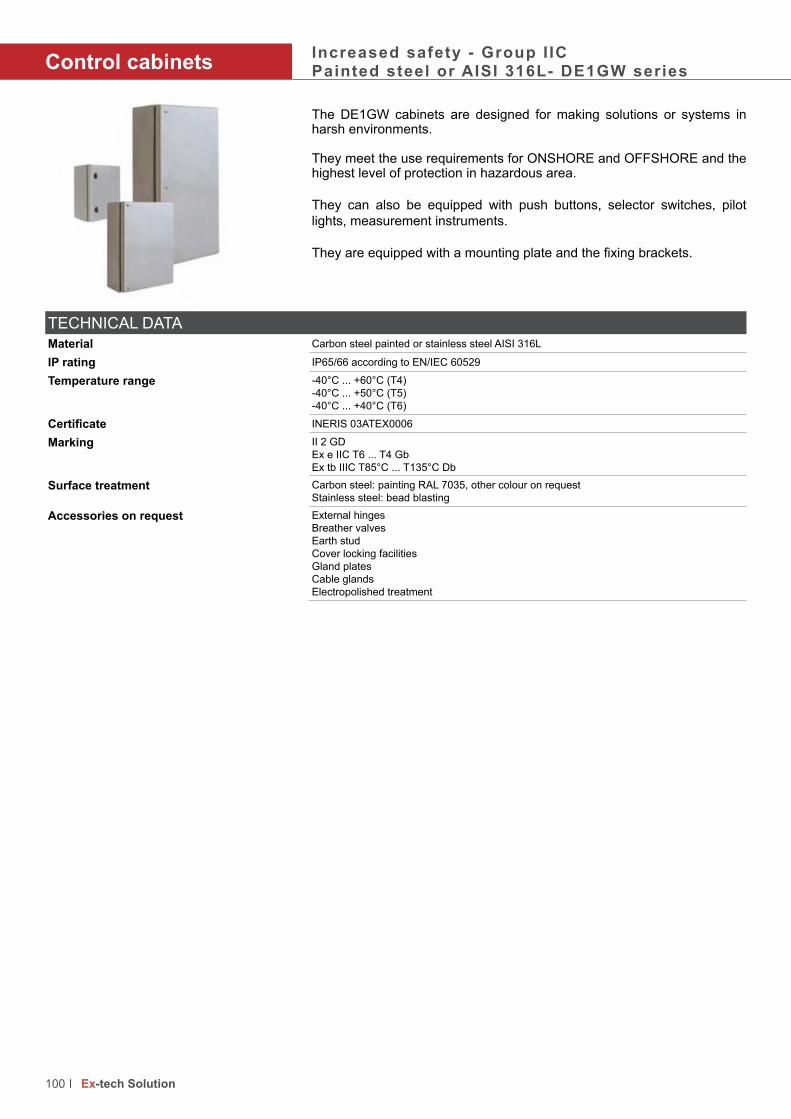
100 Ex-tech Solution
Control cabinetsIncreased safety - Group I ICPainted steel or AISI 316L- DE1GW series
The DE1GW cabinets are designed for making solutions or systems in harsh environments.
They meet the use requirements for ONSHORE and OFFSHORE and the highest level of protection in hazardous area.
They can also be equipped with push buttons, selector switches, pilot
lights, measurement instruments.
They are equipped with a mounting plate and the fixing brackets.
TECHNICAL DATA
Material Carbon steel painted or stainless steel AISI 316L
IP rating IP65/66 according to EN/IEC 60529
Temperature range -40°C ... +60°C (T4)
-40°C ... +50°C (T5)
-40°C ... +40°C (T6)
Certificate INERIS 03ATEX0006
Marking II 2 GD
Ex e IIC T6 ... T4 Gb
Ex tb IIIC T85°C ... T135°C Db
Surface treatment Carbon steel: painting RAL 7035, other colour on request
Stainless steel: bead blasting
Accessories on request External hinges
Breather valves
Earth stud
Cover locking facilities
Gland plates
Cable glands
Electropolished treatment

101 Ex-tech Solution
They are equipped with a mounting plate and the fixing brackets.
DimensionsProduct codes carbon steel
Product codes stainless steel
External Fixing Max. dissipated power Volume Weight
A B C See drawing at Tamb = 40°C (W) (dm3) (kg)
DE1GW302020 DE1GWS302020 200 300 200 “ 30 W 12 5
DE1GW302515 DE1GWS302515 250 300 150 “ 30 W 11 5.15
DE1GW282820 DE1GWS282820 280 280 200 “ 40 W 15 7
DE1GW403020 DE1GWS403020 300 400 200 “ 50 W 24 8.6
DE1GW383820 DE1GWS383820 380 380 200 “ 50 W 29 9.3
DE1GW385720 DE1GWS385720 570 380 200 “ 65 W 43 11.2
DE1GW504025 DE1GWS504025 400 500 250 “ 90 W 50 14.1
DE1GW575720 DE1GWS575720 570 570 200 “ 105 W 65 17.9
DE1GW577627 DE1GWS577627 760 570 270 “ 140 W 117 23.9
DE1GW706030 DE1GWS706030 600 700 300 “ 180 W 126 26.1
DE1GW907030 DE1GWS907030 700 900 300 “ 240 W 189 49.8
DE1GW769527 DE1GWS769527 950 760 270 “ 240 W 195 36.7
Other sizes available on request
Number maximum of entries per sideProduct code M16 M18 M20 M25 M32 M40 M50 M63
DE1GW302020 10 10 10 8 5 3 2 -
DE1GW302515 10 10 10 8 5 3 2 -
DE1GW282820 10 10 10 8 5 3 2 -
DE1GW403020 28 24 24 18 15 8 6 2
DE1GW383820 28 24 24 18 15 8 6 2
DE1GW385720 66 50 50 45 28 18 15 6
DE1GW504025 66 50 50 45 28 18 15 6
DE1GW575720 66 50 50 45 28 18 15 6
DE1GW577627 152 112 112 75 60 40 24 15
DE1GW706030 152 112 112 75 60 40 24 15
DE1GW907030 184 133 133 90 75 48 30 21
DE1GW769527 184 133 133 90 75 48 30 21
B
B - 50
B + 50
A +
50
A -
50
C
A

102 Ex-tech Solution

103 Ex-tech Solution
Lighting
Content Page
Anodized fluorescent lighting fixtures
TNAML series 104
TNAML option 106

Fluorescent lightingEncapsulationAnodized aluminium - TNAML series
• 100% encapsulated, maintenance free design requiring only visual inspection to IEC/EN 60079-17
• 10 years operational warranty* assures favourable total cost of
ownership
• Easy and flexible installation via slide guides• Seawater resistant anodized aluminium (NORSOK 121)
• Tempered glass, very high impact resistant, IK10 (20 joules)
• High light output efficiency (>80%) - Less luminaries required for same lighting level
• Optional battery powered, 90/180 minutes functionality, battery
functionality -40ºC to +30ºC - Emergency light by LEDs
• No condensation
• Self-cleaning glass
• Black start for unmanned platforms
TECHNICAL DATA
Material Anodized aluminium seawater resistant in accordance with Norsok 121Tempered glass high impact resistance
IP rating IP68 according to EN/IEC 60529
Temperature range -20°C ... +55°C-20°C ... +30°C for emergency function
Certificates DEKRA 11ATEX0133IECEx DEK11.0075
Marking ATEX
II 2 GD
Ex e mb II T6 ... T5
Ex tD A21 T80°C ... T100°C
IECEx
II 2 GD
Ex e mb IIC T6 ...T5
Ex tD A21 T80°C ... T100°C
Standards ROHS 2002/95/EC REACH 2006/121/EC HACCP by DEKRA 06540-QUA/Ex
Impact rating IK 10 (20 joules)
Visual inspection Visual in accordance with EN 60079-17
Lamps Pre-mounted long life, colour 4000K
Voltage 220-264 VAC 50/60Hz
Ballast Electronic with end of life protection preheated start
Emergency batteries Disconnecting possibility during installation by “B” terminal
Battery life time 300 cycles, automatic random, test each 100 days
Entries 2 x M25 cable glands
Vibration According to IEC60721-2-3 Ed and IEC68-2-6
Frequency range: 1-150 Hz - Sweep rate: 1 octave per minute
Amplitude: 5 mm (1 ... 10 Hz) - Sweep cycle: 10
Acceleration: 2 gn (10 ... 150 Hz) - Direction: 3
Total cost of ownership
The benefits of installing TNAML can be shown by using a Total Cost of Ownership tool. The calculation shows the LIFETIME COST SAVINGS using the data of the
client.
104 Ex-tech Solution

• 100% encapsulated, maintenance free design requiring only visual
•
• Easy and flexible installation via slide guides• • • High light output efficiency (>80%) - Less luminaries required for same
•
• • •
Product code Zone of use A (mm) Emergency light Watt Voltage Weight Lumen
TNAMLG218 GAS 1 & 21 738 - 2 x 18 W 220-264 VAC 7.1 kg 2600
TNAMLG236 GAS 1 & 21 1348 - 2 x 36 W 220-264 VAC 9,7 kg 6000
TNAMLG258 GAS 1 & 21 1648 - 2 x 58 W 220-264 VAC 12,4 kg 10400
TNAMLD218 DUST 2 & 22 738 - 2 x 18 W 220-264 VAC 7.1 kg 2600
TNAMLD236 DUST 2 & 22 1348 - 2 x 36 W 220-264 VAC 9,7 kg 6000
TNAMLD258 DUST 2 & 22 1648 - 2 x 58 W 220-264 VAC 12,4 kg 10400
TNAMLG218-E1 GAS 1 & 21 898 90 minutes, 2 LEDs 2 x 18 W 220-264 VAC 9,4 kg 2600
TNAMLG218-E2 GAS 1 & 21 898 180 minutes, 2 LEDs 2 x 18 W 220-264 VAC 9,4 kg 2600
TNAMLG236-E1 GAS 1 & 21 1348 90 minutes, 2 LEDs 2 x 36 W 220-264 VAC 11,3 kg 6000
TNAMLG236-E2 GAS 1 & 21 1348 180 minutes, 2 LEDs 2 x 36 W 220-264 VAC 11,3 kg 6000
TNAMLG258-E1 GAS 1 & 21 1648 90 minutes, 2 LEDs 2 x 58 W 220-264 VAC 14,2 kg 10400
TNAMLG258-E2 GAS 1 & 21 1648 180 minutes, 2 LEDs 2 x 58 W 220-264 VAC 14,2 kg 10400
TNAMLD218-E1 DUST 2 & 22 898 90 minutes, 2 LEDs 2 x 18 W 220-264 VAC 9,4 kg 2600
TNAMLD218-E2 DUST 2 & 22 898 180 minutes, 2 LEDs 2 x 18 W 220-264 VAC 9,4 kg 2600
TNAMLD236-E1 DUST 2 & 22 1348 90 minutes, 2 LEDs 2 x 36 W 220-264 VAC 11,3 kg 6000
TNAMLD236-E2 DUST 2 & 22 1348 180 minutes, 2 LEDs 2 x 36 W 220-264 VAC 11,3 kg 6000
TNAMLD258-E1 DUST 2 & 22 1648 90 minutes, 2 LEDs 2 x 58 W 220-264 VAC 14,2 kg 10400
TNAMLD258-E2 DUST 2 & 22 1648 180 minutes, 2 LEDs 2 x 58 W 220-264 VAC 14,2 kg 10400
Outline dimensions (mm)
15
8
216
17
8
A
Standard lighting Emergency lighting
Light distribution curve
105 Ex-tech Solution

Fluorescent lightingEncapsulationAnodized aluminium - TNAML series
Options
Product code Description
TNAML V1 110/120 VAC - 50/60 Hz - ONLY for 2 x 18 W and 2 x 36 W
TNAML L1 Lamp colour 3000K
TNAML L2 Lamp colour 6500K
TNAML E1 Electrical connection by 8 meter permanent flying lead, braidedTNAML M1 Pole mounting brackets
TNAML M2 Ceiling mounting brackets
TNAML M3 Suspended mounting brackets
TNAML M4 Frame in painted steel for recessed installation in modular ceiling systems
TNAML M5 Frame in stainless steel for recessed installation in modular ceiling systems
TNAML G1 Glass for use accordance with HACCP environment
TNAML G2 Frosted glass avoiding glare for low mounted fixturesTNAML S1 Safety wire for installation into a fixing arrangement on the light fittingTNAML S2 2 terminal boxes including through wiring 2.5 mm2
TNAML B1 Black start emergency light - Wireless “Black Start” function for manned/unmanned functionality
TNAML C1 Ex e Cable gland (separate package)
TNAML H1 HACCP for food industry
Frame for recessed installation in modular ceiling systems
Pole mounting brackets Suspended mounting
brackets
Ceiling mounting brackets
Options
Outline dimensions with wiring through 2 junction boxes
15
8
17
8
216 1558
106 Ex-tech Solution
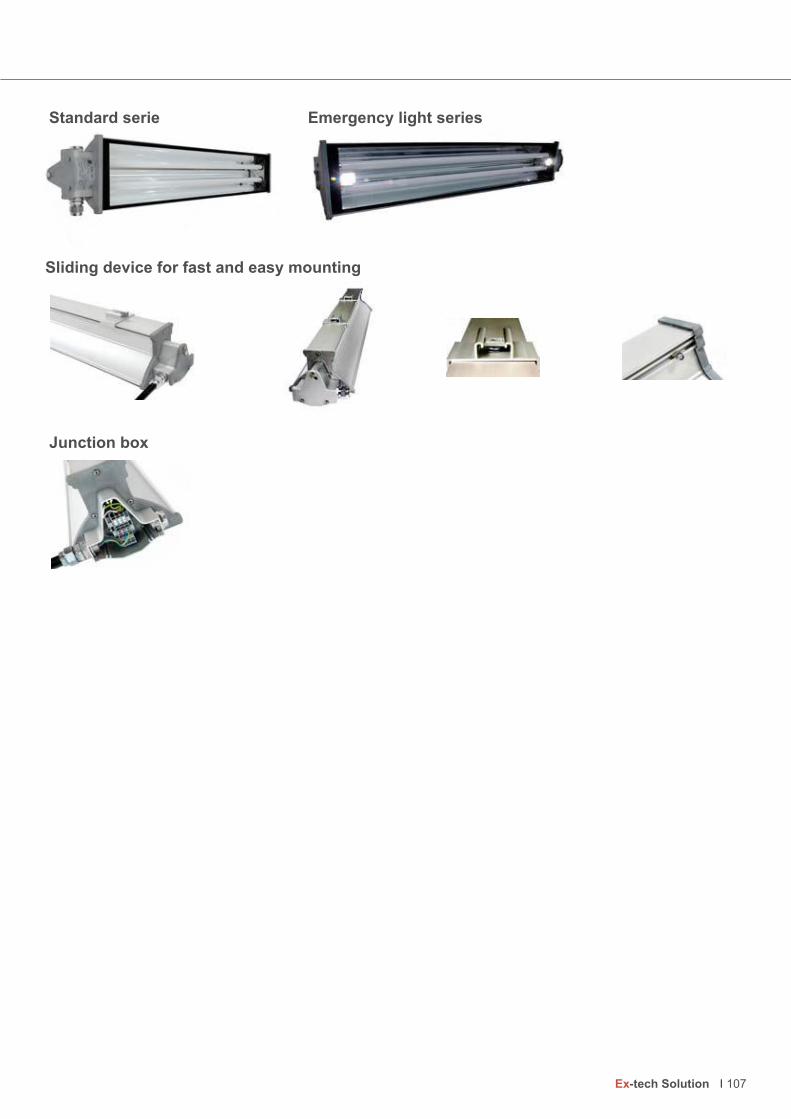
Sliding device for fast and easy mounting
Standard serie
Junction box
Emergency light series
107 Ex-tech Solution

108 Ex-tech Solution

109 Ex-tech Solution
Sensors
Content Page
Limit switches - Flameproof - Explosion gas group IIC
XCWD series - Assembled 110
ZCWD series - Unassembled 114
XC8J and ZC8J series 116
Limit switches - Increased safety
XCK and XCR series 118
Photocell - Flameproof - Explosion gas group IIC
XUWB series 124
Pressure switches - Flameproof - Explosion gas group IIC
XMLW series 126

Limit switchesFlameproof - Group I ICXCWD series
The XCWD limit switches is a safe bet for controlling movement. It benefits from the latest developments: modularity, compactness, a very broad range of actuators.
They are designed for intensive use and a very good repeatability.
They are provided in complete assemblies or variable composition with:
• 2 or 4 electrically separate snap action contacts• Heads that can be adjusted from 15° to 15° on 360° relative to the body
• can substitute the previous range XCWA and XCWF
TECHNICAL DATA
Material Zamac
IP rating IP66/67 according to EN/IEC 60529
Operating temperature -20°C ... +60°C
Certificate INERIS 03ATEX0083X
Marking II 2 GD
Ex d IIC T6 Gb
Ex tb IIIC T85°C Db
Repeat accuracy 0.05 mm on the tripping points, with 1 million operation cycles for actuator with end plunger
Shock resistance 25 gn (18ms) according to IEC 60068-2-27
Vibration resistance 5 gn according to IEC 60068-2-27
Rated thermal current 6 A for 2 contacts according to versions, 3 A for 4 contacts
Rated insulation voltage 400 V according to IEC 60947-5-1
Contact blocks Snap action - 1 x NC + 1 x NO or 2 x NC + 2 x NO
Resistance across terminals ≤ 25 mΩ according to IEC 60255-7 category 3
Electrical features of the contacts Switches with 2 contacts
AC-15 ; C300 (Ue = 240 V, Ie = 1.5 A)DC-13 ; R300 (Ue = 250 V, Ie = 0.1 A)
Switches with 4 contacts
AC-15 ; C300 (Ue = 240 V, Ie = 0.75 A)DC-13 ; R300 (Ue = 250 V, Ie = 0.1 A)
110 Ex-tech Solution

The XCWD limit switches is a safe bet for controlling movement. It benefits
• 2 or 4 electrically separate snap action contacts• Heads that can be adjusted from 15° to 15° on 360° relative to the
• can substitute the previous range XCWA and XCWF
Head with straight movement
Fixing by the body
Actuator type Metal end plunger Steel roller plunger
2 contacts 4 contacts 2 contacts 4 contacts
1 m cable length XCWD2110L1 XCWD4110L1 XCWD2102L1 XCWD4102L12 m cable length XCWD2110L2 XCWD4110L2 XCWD2102L2 XCWD4102L25 m cable length XCWD2110L5 XCWD4110L5 XCWD2102L5 XCWD4102L510 m cable length XCWD2110L10 XCWD4110L10 XCWD2102L10 XCWD4102L10
Head with straight movement
Fixing by the head
Actuator type Metal end plunger - M12 Steel roller plunger - M12
2 contacts 4 contacts 2 contacts 4 contacts
1 m cable length XCWD21F0L1 XCWD410L1 XCWD21F2L1 XCWD41F2L12 m cable length XCWD21F0L2 XCWD410L2 XCWD21F2L2 XCWD41F2L25 m cable length XCWD21F0L5 XCWD410L5 XCWD21F2L5 XCWD41F2L510 m cable length XCWD21F0L10 XCWD410L10 XCWD21F2L10 XCWD41F2L10
Head with angular movement
Fixing by the body
Actuator type Thermoplastic roller lever Steel roller lever
2 contacts 4 contacts 2 contacts 4 contacts
1 m cable length XCWD2115L1 XCWD4115L1 XCWD2116L1 XCWD4116L12 m cable length XCWD2115L2 XCWD4115L2 XCWD2116L2 XCWD4116L25 m cable length XCWD2115L5 XCWD4115L5 XCWD2116L5 XCWD4116L510 m cable length XCWD2115L10 XCWD4115L10 XCWD2116L10 XCWD4116L10
Head with angular movement
Fixing by the body
Actuator type Lever variable length with thermoplastic roller Lever variable length with steel roller
2 contacts 4 contacts 2 contacts 4 contacts
1 m cable length XCWD2145L1 XCWD4145L1 XCWD2146L1 XCWD4146L12 m cable length XCWD2145L2 XCWD4145L2 XCWD2146L2 XCWD4146L25 m cable length XCWD2145L5 XCWD4145L5 XCWD2146L5 XCWD4146L510 m cable length XCWD2145L10 XCWD4145L10 XCWD2146L10 XCWD4146L10
111 Ex-tech Solution

Switch actuation On end By 30° cam
Maximum actuation speed 0.5 m/s 0.5 m/s
Mechanical durability 10 million operating cycles
Minimum force or torque for tripping 8.5 N 7 N
for positive opening 42.5 N 35 N
Cabling PvR cable: 5 x 0.75 mm2 for 2-pole contact versions, 9 x 0.34 mm2 for 4-pole contact versions
10
22
.5
Ø 7
16
4 x Ø 4.2
12
.41
44
0
66
.4
20
30
3.5
Ø 12 20
.4
33
Ø 11.6
Limit switchesFlameproof - Group I ICXCWD series
Switch actuation On end By 30° cam
Maximum actuation speed 0.5 m/s 0.1 m/s
Mechanical durability 10 million operating cycles
Minimum force or torque for tripping 8.5 N 7 N
for positive opening 42.5 N 35 N
Cabling PvR cable: 5 x 0.75 mm2 for 2-pole contact versions, 9 x 0.34 mm2 for 4-pole contact versions
3.5
M12 x 1
38
50
.4
8 m
ax.
Ø 10.6
16
4 x Ø 4.2
12
.41
44
0
66
.4
20
30
26
38
.4
M12 x 1
8 m
ax.Ø 7
112 Ex-tech Solution

All actuators can be adjusted from 15° to 15° on 360° relative to the body
RD-W
HRD
VT
VT-W
H
GN-YE
BK-W
HBK
BU
BN
Switches with 4-pole contacts NC + NC + NO + NOsnap action
BK-W
HBK
BU
BN
GN-YE
Switches with 2-pole contacts NC + NOsnap action
Contacts blocks
Switch actuation By 30° cam By 30° cam
Maximum actuation speed 0.1 m/s 1.5 m/s
Mechanical durability 10 million operating cycles
Minimum force or torque for tripping 7 N 0.1 N.m
for positive opening 35 N 0.5 N.m
Cabling PvR cable: 5 x 0.75 mm2 for 2-pole contact versions, 9 x 0.34 mm2 for 4-pole contact versions
5.5
24
32.4
44
56
.4
34
.4
Ø 16
5.5
33
33
.5 …
83
.5
Ø 16
43
… 9
3
55
.4 …
10
5.4
16
4 x Ø 4.2
12
.41
44
0
66
.4
20
30
113 Ex-tech Solution

Variable components - Actuator and body unassembled
Snap action contacts
ZCE21 ZCE27 ZCE28 ZCE24
ZCE62 ZCE63 ZCE64 ZCE65 ZCE66
ZCEF0 ZCEF2 ZCE2A (1) ZCEGA (2)
ZCE02 ZCE29 (1) ZCE2A (2) ZCE13 ZCE07 (1) ZCEA7 (2) ZCE08 (1) ZCEA8 (2) ZCE06 (1) ZCEA6 (2)
ZCE10 ZCE11 (1) ZCE1A (2) ZCE14
(1) Soufflet en nitrile pour utilisation à l’intérieur d’un local (2) Soufflet en silicone pour utilisation à l’extérieur d’un local
A levier à galet thermoplastique sens d’attaque latéral
A levier à galet thermoplastique sens d’attaque vertical
A levier à galet thermoplastique sens d’attaque latéral ou vertical
A levier à galet en acier escamotable
A poussoir à galet en acier
A poussoirà galet en acier avec soufflet
A poussoirà galet en acier avec soufflet
A poussoirà bille en acier
A poussoir de côté métallique
A poussoir de côté à galet horizontal
A poussoir de côté à galet vertical
A poussoir de côté à bille
M12 à poussoir Métallique
M12 à poussoir à galet en acier
M12 à poussoir à galet en acier avec soufflet
A tige à ressort avec embout thermoplastique
A tige à ressort A tige souple à ressort
A poussoirmétallique
A poussoir métallique avec soufflet
A poussoir métallique avec soufflet
A poussoirmétalliqueréglable
A poussoir de côté métallique réglable
Roller leverthermoplasticone-way horizontalactuation
Roller leverthermoplasticone-way vertical actuation
Roller leverthermoplasticone-way horizontal orvertical actuation
Retractable roller lever, steel
Adjustable side plunger, metal
Side plunger, metal
Side steel roller plungerhorizontal
Side steel roller plungervertical
Side ballbearing plunger
M12 with elastomer boot Wobble stick with coil spring extension and thermoplastic end
Wobble stick with coil spring extension
Cat whisker
A poussoirà galeten acieravecsoufflet
A poussoirmétallique
A poussoirmétallique avec soufflet
A poussoirmétallique réglable
(1) Nitrile boot for use within a local(2) Silicone boot for use outside of a local
ZCWE21 ZCWE27 ZCWE28 ZCWE24
ZCWE62 ZCWE63 ZCWE64 ZCWE65 ZCWE66
ZCWEG1 (1)
ZCWE29 (1)
ZCWE2A (2)
ZCWE07 (1)
ZCWEA7 (2)
ZCWE08 (1)
ZCWEA8 (2)
ZCWE06 (1)
ZCWEA6 (2)
ZCWE1A (2)
A poussoir métallique avec soufflet
A poussoir métallique avec soufflet
Amrégl
soufflet soufflet
Metal plunger with elastomer boot
Steel ball bearing plunger
Steel rod plunger with elastomer boot
Metal plunger with elastomer boot
ZCWE13
ZCWE11 (1) ZCWE14
Adjustable metal plunger
Part number of the body - When ordering specify the selected actuator
Cable length 2 contacts ( 1NC + 1NO) 4 contacts (2NC + 2NO)
1 m long ZCWD21L1 ZCWD41L1
2 m long ZCWD21L2 ZCWD41L2
5 m long ZCWD21L5 ZCWD41L5
10 m long ZCWD21L10 ZCWD41L10
Limit switchesFlameproof - Group I ICXCWD series
114 Ex-tech Solution

Variable components - Actuator, head and body unassembled
Snap action contacts
A levier à rouleau céramique
ZCY22
A levier à ressort embout thermoplastique
ZCY81
A levier à ressort à tige métallique
ZCY91
A levier pliable à galet thermoplastique de longueur variable
ZCY44
A levier à galet thermoplastique de longueur variable
ZCY45
A levier pliable à galet acier de longueur variable
ZCY46
A levier pliable à galet acier de longueur variable
ZCY48
A levier à galet thermoplastique pistes 20/36 mm
ZCY18
A levier à galet acier pistes 20/36 mm
ZCY19
A levier à galet roulement billepistes 20/36
ZCY12
A levier à galet à thermoplastique pistes 20/36 mm
ZCY15
A levier à galet acier pistes 20/36 mm
ZCY16
A tige ronde acier Ø 3 mm L = 125 mm
ZCY53
A tige carrée acier 3 mm L = 125 mm
ZCY54
A tige ronde en fibre de verre Ø 3 mm L = 125 mm
ZCY55
A tige ronde thermoplastique Ø 6 mm L = 200 mm
ZCY56
A levier à galet acier à roulement à billes pistes 20/36 mm
ZCY17
A levier à galet thermoplastique pistes 20/36 mm
ZCY25
A levier à galet acier pistes 20/36 mm
ZCY26
A levier à galet acier à roulement à billes pistes 20/36 mm
ZCY23
Round rod, steel
Ø 3 mm
L = 125 mm
Square rod, steel
3 mm
L = 125 mm
Round rod, fibreglass
Ø 3 mm
L = 125 mm
Round rod, thermoplastic
Ø 3 mm
L = 200 mm
ZCWY53 ZCWY54 ZCWY55 ZCWY59
Coil spring lever with thermoplastic end
Ceramic roller lever
Spring rod lever
Adjustable length flexible lever arm with thermoplastic roller
ZCWY44
Thermoplastic roller levertracks 20/36 mm
Steel roller lever tracks 20/36 mm
Ball bearing roller lever, tracks 20/36 mm
Spring return
for right AND left actuation
ZCWE01
ZCWY22 ZCWY81 ZCWY91
ZCWY48
ZCWY18 ZCWY19 ZCWY12 ZCY16
ZCWY17 ZCWY25 ZCWY26 ZCWY23
Ball bearing roller lever tracks 24/31 mm
Thermoplastic roller levertracks 16/39 mm
Steel roller lever tracks16/39 mm
Ball beraing roller lever tracks 16/39 mm
Y17 Y25
galet
Y26
Aacià pi
ZC
e de
Y44 Y45
e à
Y46
Agalde lvari
ZC
Y18 Y19
galet
Y12 ZC
Y17 Y25 Y26 ZC
Adjustable length flexible lever arm with steel roller
Part number of the body - When ordering specify the selected actuator
Cable length 2 contacts ( 1NC + 1NO) 4 contacts (2NC + 2NO)
1 m long ZCWD21L1 ZCWD41L1
2 m long ZCWD21L2 ZCWD41L2
5 m long ZCWD21L5 ZCWD41L5
10 m long ZCWD21L10 ZCWD41L10
115 Ex-tech Solution

Limit switchesFlameproof - Group I ICXC8J and ZC8J series
The XC8JC and ZC8JC, made in cast iron, are extremely robust and reliable.
Their high performances added to the very important choice of actuators make them suitable in many applications.
For special applications, the heads can be designed according to the needs.
TECHNICAL DATA
Material Painted cast iron
IP rating IP66/67 according to EN/IEC 60529
Temperature range -20°C or - 50°C ... +60°C or +80°C
Certificate INERIS 03ATEX0123
Marking II 2 GD
Ex d IIC T6 ... T5 Gb
Ex tb IIIC T85°C ... T100°C Db
Rated thermal current 6 A
Insulation voltage 500 V
Contact block 1 x O+C - 1 pole snap-action contact
Resistance between terminals ≤ 25 mΩ
Power use Category: AC11, DC11
Mechanical durability 10 million of operation cycles
116 Ex-tech Solution

The XC8JC and ZC8JC, made in cast iron, are extremely robust and
Product code Actuators with straight movement Add the cable entry codes according to (6)
Weight (kg)
XC8JC161P1 Steel plunger (1) • • • 2
XC8JC162P1 Roller plunger (2) • • • 2
XC8JC163P1 Side plunger (2) • • • 2
Product code Heads with angular movement Actuation direction Add the cable entry codes according to (6)
XC8JC10111P1 Thermoplastic roller lever (3) Actuation from left and right • • • 2,2
XC8JC10511P1 Actuation from left or right (5) • • • 2,2
XC8JC10131P1 Variable length (3) Actuation from left and right • • • 2,2
XC8JC10531P1 Actuation from left or right (5) • • • 2,2
XC8JC10151P1 Steel rod (4)
3 mm, length: 125 mm
Actuation from left and right • • • 2,2
XC8JC10551P1 Actuation from left or right (5) • • • 2,2
ZC8JC1P1 Limit switch body only for plunger and
rotary heads for plunger and rotary
heads
1 contact “OC” • • • 2,2
ZC8JC2P1 2 x “OC”, simultaneous • • • 2,2
ZC8JC4P1 1 contact “OC” + 1 contact “OC”, 2 steps • • • 2,2
Cable entry code (6) Codes below to add to the product code
Thread M20 1F for no-armoured cable with clamping device 1 I C
4F for armoured cable 4 I
Without cable gland 5
(1) Actuation on end. Maximum actuation speed: 0.5 m/s (2) Actuation by cam 30°. Maximum actuation speed: 0.5 m/s
(3) Actuation by cam 30°. Maximum actuation speed: 1.5 m/s (4) Actuation by cylindrical finger. Maximum actuation speed: 1.5 m/s
(5) By adjusting the operating head
Ø 12
75
56
76
==
71
50
33
77
20
7
4
27
44
79
75
56
76
2 x Ø 7
Ø 22
==
21
5
50
33
49 …76
5
77
XC8JC161P1 XC8-JC162P1 XC8-JC163P1 XC8JC10111P1XC8JC10511P1
XC8JC10131P1XC8JC10531P1
XC8JC10151P1 ZC8JC1P1
ZC8JC2P1
ZC8JC4P1
117 Ex-tech Solution

Limit switchesIncreased safety - Group I ICXCK and XCR series
This extensive range of products and components is well known worldwide
for its reliability, its design and the many opportunities in the choice of
heads.
They allow the customers to implement and operate them in numerous
places of their process.
TECHNICAL DATA
Material (body) Zamac
IP rating IP65 according to EN/IEC 60529
Temperature range XCKW: -40°C ... +60°CXCR.W: -30°C ... +60°C
Certificates INERIS 03ATEX0038XINERIS 03ATEX0039X
IECEx INE 12.0029XIECEx INE 12.0030X
Marking II 2 GD
Ex d e IIC T6 Gb
Ex tb IIIC T85°C Db
Contact block 500 V, 3A
118 Ex-tech Solution

For lifting equipment, conveyors
Fixing distance 85 x 75 mm
Actuator type Square rod 6 mm spring
return position
Thermoplastic roller lever Ø
30 mm
Thermoplastic roller lever Ø
50 mm
Metallic square rod in cross,
stay put
Conveyor belt shift monitoringLever
galvanizedLever in
stainless steel
Two 2-pole NC + NO contacts,
both operate in each directionXCRAW111 XCRAW121 XCRAW151 XCREW181 (2)
Two 2-pole NC + NO contacts,
one operates in each directionXCRBW111 XCRBW121 XCRBW151 XCRFW171 (3)
2 single contacts “O + C” XCRTW115 XCRTW215Actuation speed 1.5 m/s
Mechanical durability 10 million operations 0.3 million operations
Contact type Snap action
Cable entry 1 entry ISO M20 for cable of Ø 8 to 13 mm
(2) Metallic rods in cross
(3) Metallic rods in “T”
For lifting equipment, conveyors, handling devices
Fixing distance 61.5 mm
Actuator type Metallic rods in cross Metallic rods in cross, reversed head
Two 2-pole NC + NC XCKWMR54D1H29 XCKWMR54D2H29Actuation speed 1.5 m/s
Mechanical durability 2 million operations
Contact type Staggered, slow break
Cable entry 2 entries with blind plug, 1 entry with cable gland ISO M20 for cable Ø 8 to 13mm
Overall use
Fixing distance 41 mm
Actuator type Metal end plunger Steel roller plunger
Thermoplastic roller lever
Thermoplastic roller lever
”Cat’s wisker”
NO + NC XCKWM2110H29 XCKWM2102H29 XCKWM2121H29 XCKWM2115H29 XCKWM2106H29Actuation speed 0.5 m/s 1.5 m/s 0.5 m/s
Mechanical durability 20 million operations 10 million operations
Contact type Snap action
Cable entry 2 entries with blind plug, 1 entry with cable gland ISO M20 for cable Ø 8 to 13mm
119 Ex-tech Solution

Compact range
Fixing distance 20 mm
Actuator type Metal end plunger Booted metal end
plunger
Steel roller
plunger
Plastic roller,
horizontal
actuation
Plastic roller,
vertical actuation
Plastic roller, ver-
tical or horizontal
actuation
NC + NC XCKWD2110P16 XCKWD2111P16 XCKWD2102P16 XCKWD2121P16 XCKWD2127P16 XCKWD2128P16NO + NC XCKWD2910P16 XCKWD2911P16 XCKWD2902P16 XCKWD2921P16 XCKWD2927P16 XCKWD2928P16Actuation speed 0.5 m/s 1 m/s
Durability 15 million operations 10 million operation 15 million operations
Type of contact Snap action
Cable entry 1 entry M16 for câble Ø 5 to 8 mm
Compact rangeFixing distance 30 x 60 mm
Actuator type Metal end plunger Steel roller plunger
Steel roller lever Thermoplastic roller lever
Variable length thermoplastic
roller lever
Round lever Ø 6 mm polyamide
L = 200 mm
Contact NO + NC XCKWJ2161H29 XCKWJ2167H29 XCKWJ210513H29 XCKWJ210511H29 XCKWJ210541H29 XCKWJ210559H29Actuation speed 0.5 m/s 1 m/s 1.5 m/s
Durability 30 million operations 25 million operation 30 million operations 20 million operations
Type of contact Snap action
Cable entry 1 entry ISO M20 for cable Ø 8 to 13 mm
Compact rangeFixing distance 20mm
Actuator type Thermoplastic
roller lever
Thermoplastic
roller lever
Ø 50 mm
Variable length
plastic roller
lever
Variable length
plastic roller Ø
50 mm
”Cat’s wisker” M18 head
Metal end
plunger
M18 steel roller
end plunger
NO + NC XCKWD2118P16 XCKWD2139P16 XCKWD2145P16 XCKWD2149P16 XCKWD2106P16 XCKWD21H0P16 XCKWD21H2P16NO + NC XCKWD2918P16 XCKWD2939P16 XCKWD2945P16 XCKWD2949P16 XCKWD2906P16 XCKWD29H0P16 XCKWD29H2P16Actuation speed 1.5 m/s 1 m/s 0.5 m/s
Durability 10 million operations 5 million 10 million operations
Type of contact Snap action
Cable entry 1 entry ISO M16 for cable Ø 5 to 8 mm
Limit switchesFlameproof - Group I ICXCK and XCR series
120 Ex-tech Solution
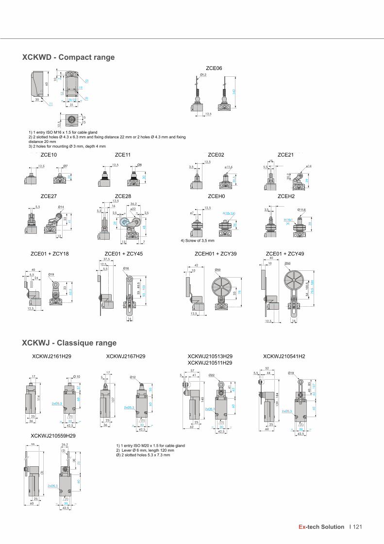
XCKWJ - Classique rangeLimit switch, Classic, XCKWJ (metal) XCKWJ2161H29 XCKWJ2167H29 XCKWJ210513H29 XCKWJ210541H29
92H115012JWKCX
X(1) 1 ISO M20 x 1,5 for cable gland.
CKWJ210559H29
(2) lever ø 6, length 200 mm. (3) 282 maxi. (4) 190 maxi. (5) 212 maxi. ø: 2 oblongs holes ø 5,3 x 7,3.
36
25
114
17
(1)
42,5
30= =
60
37
(1)
42,5
30= =
60
50
36
25
12
7
17
5
63
60
30
42,5
==
41
(1)25
57
62
5
140
41
25
52
60
5,5
13
9…
18
4
44
62
…1
07
60
30
42,5
==
40
…8
5
(1)
60
25
(3)
48
(1)
42,5
30= =
60
(5)(4
)
(2)
26,2
XCKWJ2161H29 XCKWJ2167H29 XCKWJ210513H29 XCKWJ210541H2 XCKWJ210511H29
XCKWJ210559H29
1) 1 entry ISO M20 x 1.5 for cable gland
2) Lever Ø 6 mm, length 120 mm
Ø) 2 slotted holes 5.3 x 7.3 mm
XCKWD - Compact range 60ECZ
(1) ISO M16 x 1,5 for cable gland. (2) 2 oblongs holes ø 4,3 x 6,3 mm pitch 22 mm or 2 holes ø 4,3 pitch 20 mm. (3) 2 holes for mounting ø 3 depth 4 mm.
12ECZ 20ECZ 11ECZ 01ECZ
2HECZ 0HECZ 82ECZ 72ECZ
ZCE01 + ZCY18 ZCE01 + ZCY45 ZCE01 + ZCY39 ZCE01 + ZCY49
Limit switch, Classic, XCKWJ (metal)
12,5
20
12,5
30
3,5
30
,5
12,5
ø 11,6 5,5
20,2
16
39
ø14
2
(2)
(1)
20/22
12
,5
15
15
30
31
19
65
(3)
10
53
5,5
12
22
41
=2,5
12,536,2
16
713
5,5
48
29
2,5=
ø22
M18x1(4)
26
12,5
ø7
38
M18x1(4)
3,5
(4) Screw thickness 3,5 mm.
37,5
5,5
12,5
16
10
42
33 78
12,5
10
16
40
12,5
40
5,524
12,5
33
52
,5
142
12,5
ZCE10 ZCE11 ZCE02 ZCE21
ZCE27 ZCE28 ZCEH0 ZCEH2
ZCE01 + ZCY18 ZCE01 + ZCY45 ZCEH01 + ZCY39 ZCE01 + ZCY49
1) 1 entry ISO M16 x 1.5 for cable gland
2) 2 slotted holes Ø 4.3 x 6.3 mm and fixing distance 22 mm or 2 holes Ø 4.3 mm and fixing distance 20 mm
3) 2 holes for mounting Ø 3 mm, depth 4 mm
ZCE06
4) Screw of 3,5 mm
121Ex-tech Solution
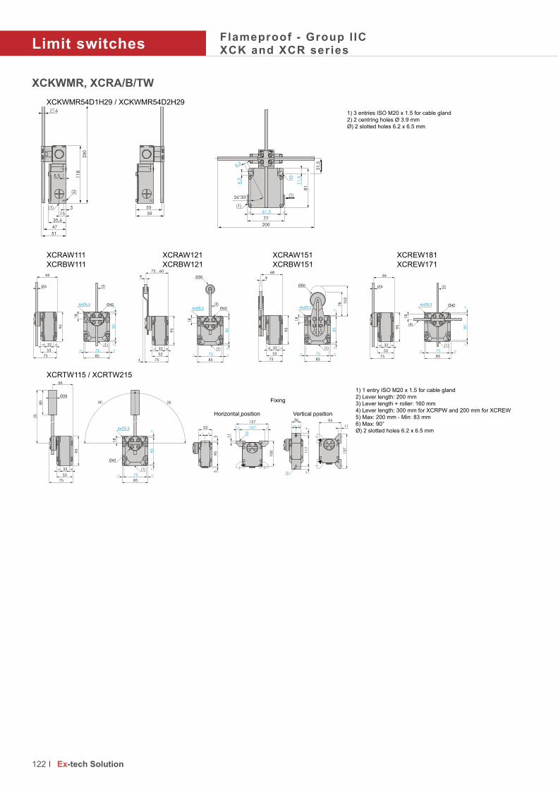
Limit switchesFlameproof - Group I ICXCK and XCR series
122 Ex-tech Solution
XCKWMR, XCRA/B/TWXCKWMR54D1H29 / XCKWMR54D2H29
(1) 3 ISO M20 x 1,5 for cable gland. (2) 2 centring holes ø 3,9. ø : 2 oblongs holes 6,2 x 6,5.
XCRAW111 XCRAW121 XCRAW151 XCREW181 XCRBW111 XCRBW121 XCRBW151 XCRFW171
XCR(1) ISO M20 x 1,5 for cable gland.
TW115 / XCRTW215
(2) Lever length: 200mm. (3) Lever length + roller: 160mm. (4) Lever length 300mm for XCRFW, 200mm for XCREW (5) 200 maxi – 83 mini (6) 90° maxi Ø: 2 oblongs holes 6,2 x 6,5.
Limit switch, Classic, XCKWM (metal)
35,6
5,5
15
(1) 5
(2)
20
0
51
47
6
11
8
59
55
77
81
11
,5
61,5= =
(1)
(1)
31
,5
200
6,2
6,5
26°30'
66
53
75
== 32
95
(2)
85
85
== 75
(1)
18
==
6
72…60
4
9
53
75
== 32
95
(3)
85
85
== 75
(1)
18
==
66
53
75
== 32
95
6
9
68
53
75
== 32
95
18
85
78
85
== 75
(1) ==
10
2
(2)
(4)
85
== 75
(1)
18
==
85
53
75
== 32
95
66
80
(5)
85
85
== 75
(1)
18
==
(6) (6)
53
==
55
95
10
0
11
127
107 ==
Horizontal position Vertical position
==
36
==
11
7
95
13
7
11
Fixing
XCRAW111 XCRAW121 XCRAW151 XCREW181 XCRBW111 XCRBW121 XCRBW151 XCREW171
XCKWMR54D1H29 / XCKWMR54D2H291) 3 entries ISO M20 x 1.5 for cable gland
2) 2 centring holes Ø 3.9 mm
Ø) 2 slotted holes 6.2 x 6.5 mm
Fixing
Horizontal position Vertical position
1) 1 entry ISO M20 x 1.5 for cable gland
2) Lever length: 200 mm
3) Lever length + roller: 160 mm
4) Lever length: 300 mm for XCRPW and 200 mm for XCREW5) Max: 200 mm - Min: 83 mm
6) Max: 90°
Ø) 2 slotted holes 6.2 x 6.5 mm
XCRTW115 / XCRTW215

XCKWM - Classique rangeLimit switch, Classic, XCKWM (metal) XCKWM2110H29 XCKWM2102H29 XCKWM2121H29 XCKWM2115H29
XCK(1) 3 ISO M20 x 1,5 for cable gland.
WM2106H29
(2) 2 x Ø 4. Ø: 2 oblongs holes 5,2 x 6,2.
41
64
30
==
88,5
30
14
(1)
48
,5
41
64
==
4
14
10
8
30
(1)
8
14
11
2,5
30
(1)
54
41
65
11,5
34,5
60,5
41
64
==
5,5
22 15
119
30
34
(1)
8
14
201
30
(1)
142,5
41
64
==
41
= 27 =
54
(2)
Back side
XCKWM2110H29 XCKWM2102H29 XCCKWM2121H29 XCKWM2115H29
XCKWM2106H29
arrière
1) 3 entries ISO M20 x 1.5 for cable gland
2) 2 holes x Ø 4
Ø) 2 slotted holes 5.2 x 6.2 mm
123 Ex-tech Solution

PhotocellsFlameproof - Group I ICXUWB series
With a footprint diameter of only 30 mm these prewired photocells, certified ATEX Ex d, can be used in all types of applications and processes.
With a nominal range from 0.6 m to 15 m, it will be able to meet all needs.
TECHNICAL DATA
Material Brass nickel platted or stainless steel AISI 316L
IP rating IP67 according to EN/IEC 60529
Temperature range -25°C ... +55°C
Certificate INERIS 06ATEX0066X
Marking II 2 GD
Ex d IIC T6 Gb
Ex tb IIIC T85°C Db
Type of transmission Infrared
Supply voltage 12 ... 24 VDC with protection against reverse polarity
Current consumption 35 mA
Maximum switching frequency 500 Hz
Electrical connection By cable 2 m for XUWB...L2By cable 5 m for XUWB...L5
Fixing diameter M30 x 1.5
124 Ex-tech Solution

With a footprint diameter of only 30 mm these prewired photocells, certified ATEX Ex d, can be used in all types of applications and processes.
Type of detection Reflex polarized Reflex Barrier
Type of output in DC circuit (static output) Product code
PNP OUTPUT - NO XUWB9APANL2 XUWB1APANL2 XUWB2APANL2RPNP OUTPUT - NC XUWB9APBNL2 XUWB1APBNL2 XUWB2APBNL2RNPN OUTPUT - NO XUWB9ANANL2 XUWB1ANANL2 XUWB2ANANL2RNPN OUTPUT - NC XUWB9ANBNL2 XUWB1ANBNL2 XUWB2ANBNL2RTransmitter to add - - XUWB2AKSNL2T
Rated operating distance in meter 2 4 15
For a length of 5m, replace L2 by L5. Example: XUWB5APANL2 becomes XUWB5APANL5
Reflector code Size
XUZC16 Standard reflector Ø 16
XUZC21 Standard reflector Ø 21
XUZC31 Standard reflector Ø 31
XUZC39 Standard reflector Ø 39
XUZC24 Reflector for short sensing ranges 24 x 21
Standard reflector Reflector for short distance of detection9
45
4
7.5
24
29
21 33
Ø 7.5
Ø 4.5
C
A B
L
M3
0 x
1.5
Ø 2
8
125 Ex-tech Solution

Pressure switchesFlameproof - Group I ICXMLW series
With a wide range of pressures, from 0.1 to 500 bars, the XMLW pressure switches allow to control fluids in hazardous areas.
They meet the highest level of protection for the explosive atmospheres.
TECHNICAL DATA
Material Zamac
IP rating IP66 according to EN/IEC 60529
Temperature range -20°C ... +60°C
Certificate INERIS 04ATEX0007
Marking For Tfluid < +65°CII 2 GD
Ex d e IIC T6 Gb
Ex tb IIIC T85°C Db
Rated thermal current 6 A
Insulation voltage 250 V
Contact block Single-pole snap action NO+NC
Electrical connection Screw terminal block, cable entry ISO M20 for cable Ø 8 to 13 mm
Short circuit protection By fuse 6 A gG (gl) to be installed outside the Ex area
Hydraulic connection 1/4” gas female - Other on request
126 Ex-tech Solution

With a wide range of pressures, from 0.1 to 500 bars, the XMLW pressure switches allow to control fluids in hazardous areas.
Pressure switch with display
Gauge Setting range upper threshold (ph)
Fluids controlled Possible differential (add to PB to get PH)
Min. low setting Min. high setting Max. high setting
XMLW-CM02T2S12 - 1 bar - 1 … - 0.14 bar Hydraulic oils, water, air 0.13 bar 0.14 bar 0.8 bar
XMLW-C001R2S12 1 bar 0.05 … 1 bar Hydraulic oils, air 0.03 bar 0.04 bar 0.8 bar
XMLW-C001S2S12 1 bar 0.005 … 1 bar Water, corrosives fluids 0.03 bar 0.04 bar 0.8 bar
XMLW-C004B2S12 4 bar 0.3 … 4 bar Hydraulic oils, water, air 0.17 bar 0.15 bar 2.5 bar
XMLW-C004C2S12 4 bar 0.3 … 4 bar Corrosive fluids 0.17 bar 0.15 bar 2.5 bar
XMLW-C010B2S12 10 bar 0.7 … 10 bar Hydraulic oils, water, air 0.45 bar 0.70 bar 8 bar
XMLW-C010C2S12 10 bar 0.7 … 10 bar Corrosive fluids 0.45 bar 0.70 bar 8 bar
XMLW-C020B2S12 20 bar 1.3 … 20 bar Oil, water, air 0.7 bar 1 bar 11 bar
XMLW-C020C2S12 20 bar 1.3 … 20 bar Corrosive fluids 0.7 bar 1 bar 11 bar
XMLW-C035B2S12 35 bar 3.5 … 35 bar Hydraulic oils, water, air 1 bar 1.5 bar 22 bar
XMLW-C035C2S12 35 bar 3.5 … 35 bar Corrosive fluids 1 bar 1.5 bar 22 bar
XMLW-C070D2S12 70 bar 7 … 70 bar Hydraulic oils, air 4.5 bar 8.9 bar 60 bar
XMLW-C070E2S12 70 bar 7 … 70 bar Fresh water, sea water 4.5 bar 8.9 bar 60 bar
XMLW-C070N2S12 70 bar 7 … 70 bar Corrosive fluids 4.5 bar 8.9 bar 60 bar
XMLW-C160D2S12 160 bar 12 … 160 bar Hydraulic oils, air 9 bar 21 bar 110 bar
XMLW-C160E2S12 160 bar 12 … 160 bar Fresh water, sea water 9 bar 21 bar 110 bar
XMLW-C160N2S12 160 bar 12 … 160 bar Corrosive fluids 9 bar 21 bar 110 bar
XMLW-C300D2S12 300 bar 22 … 300 bar Hydraulic oils, air 16 bar 35 bar 240 bar
XMLW-C300E2S12 300 bar 22 … 300 bar Fresh water, sea water 16 bar 35 bar 240 bar
XMLW-C300N2S12 300 bar 22 … 300 bar Corrosive fluids 16 bar 35 bar 240 bar
XMLW-C500D2S12 500 bar 30 … 500 bar Hydraulic oils, air 19 bar 52 bar 340 bar
XMLW-C500E2S12 500 bar 30 … 500 bar Fresh water, sea water 19 bar 52 bar 340 bar
XMLW-C500N2S12 500 bar 30 … 500 bar Corrosive fluids 19 bar 52 bar 340 bar
56
14
5
65
10
20 20
40
Ø 5.2 x 15.2
Ø 5.2
(2)
Ø 110
(1)
85
2 x Ø 5.2
23
56
120
(1)
37
Ø 5.2 x 6.7
DIN Connector
20 - 22
523(2) 11
3
46
17
.5
10
63
41
3
15
8
Ø 5.2
55
37 - 40= =
Ø 5.2 x 6.7
90
30(1)
(2)
122
DIN Connector
XMLW-C010/C020/035/070/160/300/500
XMLW-CM02T2S12, XMLW-C004B2S12, XMLW-C004C2S12
XMLW-C001
(1) Fluid entry G ¼”
(2) Electrical connection M20 x 1.5
127Ex-tech Solution
XMLW-C004B2S12, XMLW-C004C2S12,XMLW-C010 / C020 / 035XMLW-070 / 160 / 300 / 500XMLW-C001
1
2
PH
PB
0
2 4
1
2 4
1
XMLW-CM02T2S121
2
PB
PH
0
2 4
1
2 4
1

128 Ex-tech Solution
129 Ex-tech Solution
Content Page
Increased safety
Polyamide TRCG series 130
Brass nickel-platted TRCG series 132
Cable glands
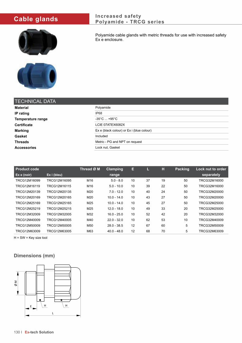
Cable glandsIncreased safetyPolyamide - TRCG series
Polyamide cable glands with metric threads for use with increased safety Ex e enclosure.
Product code Thread Ø M Clamping
range
E L H Packing Lock nut to order
separatelyEx e (noir) Ex i (bleu)
TRCG12M16099 TRCG12M16095 M16 5.0 - 8.0 10 37 19 50 TRCG32M16000
TRCG12M16119 TRCG12M16115 M16 5.0 - 10.0 10 39 22 50 TRCG32M16000
TRCG12M20139 TRCG12M20135 M20 7.0 - 12.0 10 40 24 50 TRCG32M20000
TRCG12M20169 TRCG12M20165 M20 10.0 - 14.0 10 43 27 50 TRCG32M20000
TRCG12M25169 TRCG12M25165 M25 10.0 - 14.0 10 45 27 50 TRCG32M25000
TRCG12M25219 TRCG12M25215 M25 12.0 - 18.0 10 49 33 20 TRCG32M25000
TRCG12M32009 TRCG12M32005 M32 16.0 - 25.0 10 52 42 20 TRCG32M32000
TRCG12M40009 TRCG12M40005 M40 22.0 - 32.0 10 62 53 10 TRCG32M40009
TRCG12M50009 TRCG12M50005 M50 28.0 - 38.5 12 67 60 5 TRCG32M50009
TRCG12M63009 TRCG12M63005 M63 40.0 - 48.0 12 68 70 5 TRCG32M63009
TECHNICAL DATA
Material Polyamide
IP rating IP68
Temperature range -35°C ... +95°C
Certificate LCIE 07ATEX6082X
Marking Ex e (black colour) or Ex i (blue colour)
Gasket Included
Threads Metric - PG and NPT on request
Accessories Lock nut, Gasket
130 Ex-tech Solution
Dimensions (mm)
H
Ø M
HE
L
H = SW = Key size tool

PlugsIncreased safetyPolyamide - TRCG series
Polyamide plugs with metric threads for use with increased safety Ex e enclosure.
H = SW = Key size tool
TECHNICAL DATA
Material Polyamide
IP rating IP68
Temperature range -35°C to +90°C
Certificate LCIE 03ATEX0033U
Marking Ex e
Gasket Included
Threads Metric - PG and NPT on request
Accessories Lock nut, Gasket
Dimensions
131 Ex-tech Solution
Ø M
HE
L
Product code
(Colour black)
Thread Ø M E L H Packing
Pieces
Lock nut to order
separately
TRCG22M16009 M16 8 12.0 20 50 TRCG32M16000
TRCG22M20009 M20 9 13.0 26 50 TRCG32M20000
TRCG22M25009 M25 10 15.0 32 25 TRCG32M25000
TRCG22M32009 M32 11 16.5 40 15 TRCG32M32000
TRCG22M40009 M40 12 18.0 48 10 TRCG32M40009
TRCG22M50009 M50 13 21.0 55 10 TRCG32M50009
TRCG22M63009 M63 15 24.5 70 10 TRCG32M63009
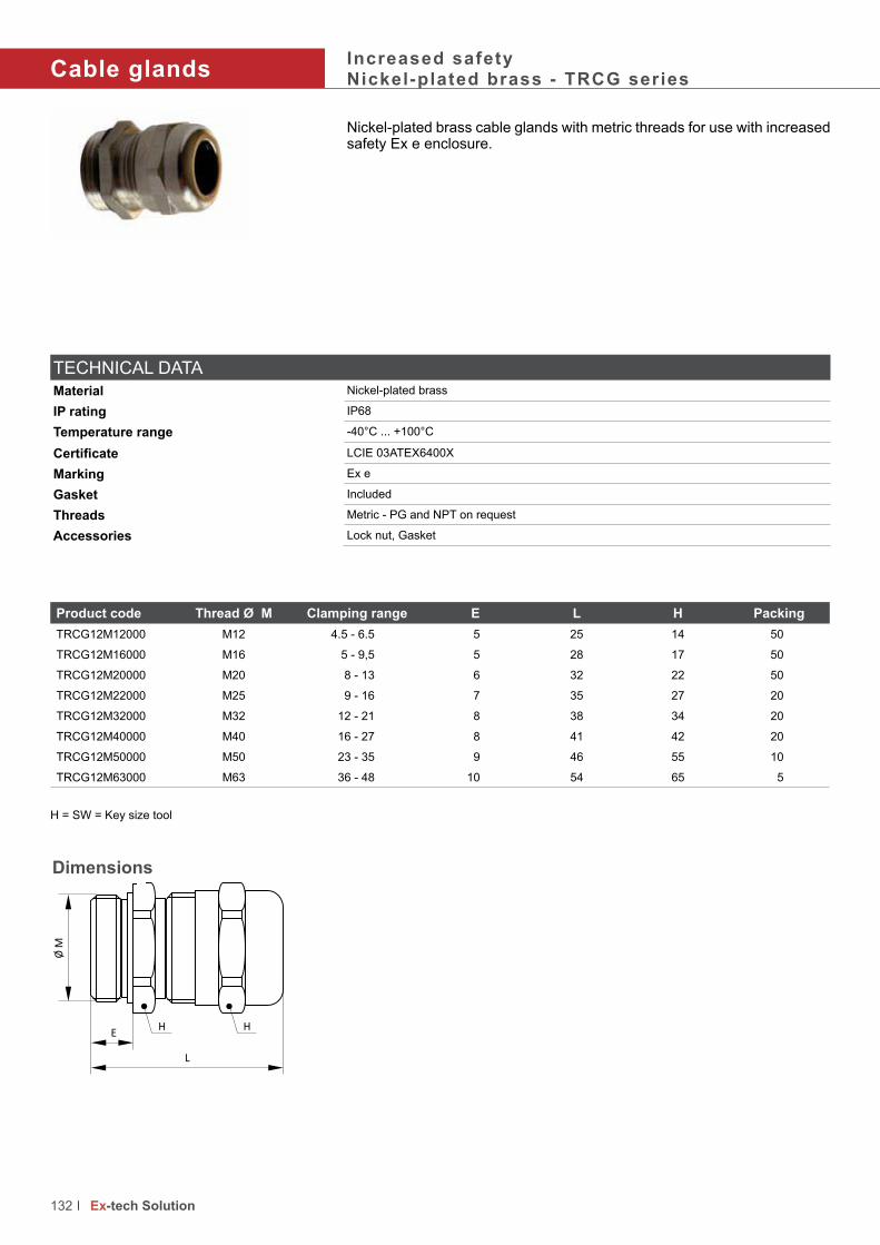
Cable glandsIncreased safetyNickel-plated brass - TRCG series
Nickel-plated brass cable glands with metric threads for use with increased safety Ex e enclosure.
Product code Thread Ø M Clamping range E L H Packing
TRCG12M12000 M12 4.5 - 6.5 5 25 14 50
TRCG12M16000 M16 5 - 9,5 5 28 17 50
TRCG12M20000 M20 8 - 13 6 32 22 50
TRCG12M22000 M25 9 - 16 7 35 27 20
TRCG12M32000 M32 12 - 21 8 38 34 20
TRCG12M40000 M40 16 - 27 8 41 42 20
TRCG12M50000 M50 23 - 35 9 46 55 10
TRCG12M63000 M63 36 - 48 10 54 65 5
TECHNICAL DATA
Material Nickel-plated brass
IP rating IP68
Temperature range -40°C ... +100°C
Certificate LCIE 03ATEX6400X
Marking Ex e
Gasket Included
Threads Metric - PG and NPT on request
Accessories Lock nut, Gasket
132 Ex-tech Solution
Dimensions
Ø M
E
L
H H
H = SW = Key size tool

PlugsIncreased safetyNickel-plated brass - TRCG series
Nickel-plated brass plugs with metric threads for use with increased safety Ex e enclosure.
Dimensions
Product code Thread Ø M E L H Packing
Pieces
Lock nut to order
separately
TRCG22M16009NP M16 8 12.0 20 50 TRCG32M16000NP
TRCG22M20009NP M20 9 13.0 26 50 TRCG32M20000NP
TRCG22M25009NP M25 10 15.0 32 25 TRCG32M25000NP
TRCG22M32009NP M32 11 16.5 40 15 TRCG32M32000NP
TRCG22M40009NP M40 12 18.0 48 10 TRCG32M40009NP
TRCG22M50009NP M50 13 21.0 55 10 TRCG32M50009NP
TRCG22M63009NP M63 15 24.5 70 10 TRCG32M63009NP
H = SW = Key size tool
TECHNICAL DATA
Material Nickel-plated brass
IP rating IP68
Temperature range -20°C to +80°C
Certificate LCIE 03ATEX0033U
Marking Ex e
Gasket Included
Threads Metric - PG and NPT on request
Accessories Lock nut, Gasket
133Ex-tech Solution
Ø M
HE
L

134 Ex-tech Signalling

Audible and Visual Signalling devices
Content Page
Beacons / Lights
BC125 and BC150 series 136
Sounders / Horns
SD125-1 and SD150-1 series 140
Sounders and beacons
SB125-1 and SB150-1 series 144
Combined products
SB125 and SB150 series 148
Status lights
SL125 and SL150 series 152
Manual call point
CP125, CP135 and CP150 series 156
Push buttons
PB125, PB135 and PB150 series 162
Junction boxes
JB125 and JB150 seires 168
Accessories and spare parts
172
135Ex-tech Signalling
Ex-tech Signalling

Beacons / LightsFlameproof - Ex d I IC - Zones 1 & 2, 21 & 22Stainless steel - BC125 series
This beacon is designed for corrosive environments and dedicated for the Oil & Gas, chemical, petrochemical, pharmacy industries, marine and offshore applications. It is available in two lighting technology options, each with four selectable flashing frequencies:
• LED with steady, rotary, fixed or blinking LED of different powers• Flashing with XENON tube of different powers
The housing in stainless steel AISI 316L is coated with a UV resistant paint. The lens is made with borosilicate glass.
Optional: control of the beacon via a telephone.
Accessories to customize the products are available (refer to page 172).
136 Ex-tech Signalling
TECHNICAL DATA
Material ENCLOSURE: Stainless steel AISI 316L LENS: Tempered borosilicate glass 3.3
Colour RED: RAL 3001 - YELLOW**: RAL1018 - BLUE**: RAL5005 - BLACK**: RAL9005
IP rating IP66/67
Ambient temperature -40°C ... +70°C
Certificates NEMKO 13ATEX1561XIECEX NEM 13.0030X
Marking II 2 GD
Ex d IIC T4 ... T6 Gb
Ex tb IIIC T135°C ... T85°C
Lens colour - Candela lens colour factor Red: 0.15 Amber: 0.51 Blue: 0.12 Green: 0.49 Clear: 1
Light type Flash tube (Xenon) LED
True light intensity 5 joules = 109 Cd 10 joules = 293 Cd 15 joules = 395 cd 21 joules = 424 Cd
5 W = 128 Cd 10W = 312 Cd
Peak light intensity 5 joules = 35970 Cd 10 joules = 66804 Cd 15 joules = 83345 Cd 21 joules = 95824 Cd
Consumption 5 joules = 10W 10 joules = 15W15 joules = 20W 21 joules = 25W
5W 10W
Time life Emissions reduced to 70% after 8 million flashes >50 000 h without luminosity decreasing
Blinking or rotary frequency 60/80/120 Times/min
100/120/150 Times/min
120/150/180 Times/min
60/75/0 Times/min (1)
60/75/100 Times/min
75/95/0 Times/min (1)
75/95/120 Times/min
(1) (0 = steady status)
Ambient Humidity* Until 95%
Power supply 12 ... 48V DC 12 ... 48V AC (50/60hz) 100 ... 240V AC (50/60hz)
Rated impulse withstand voltage 1 kV according to IEC 61000-4-5
LED operating current Power 12V DC 24V DC 48V DC 110V AC 220V AC
5W 530 mA 260 mA 120 mA 80 mA 40 mA
10W 1100 mA 530 mA 240 mA 160 mA 80 mA
XENON operating current Energy 12V DC 24V DC 48V DC 110V AC 220V AC
5J 460 mA 280 mA 140 mA 60 mA 35 mA
10J 850 mA 490 mA 250 mA 100 mA 60 mA
15J 1200 mA 700 mA 360 mA 140 mA 80 mA
21J NA 960 mA 480 mA 180 mA 110 mA
Cable entries 4 x M20, M25**, 1/2” NPT**, 3/4” NPT** or other** (Specify)
Terminals From 22 to 14 AWG - From 0.50 mm² to 2.5 mm²
Net weight 4.5 kg
External trigger** 25Hz <f<50Hz 40V<U<100V Z = 2k Ohm
* = without runoff ** = Optional - cable gland and blind plug not provided

• • Flashing with XENON tube of different powers
137Ex-tech Signalling
Meaning of lens colour usage in the international standard (IEC 60073)
Colour Meaning Action Example
RED EMERGENTDangerous state
Take immediate action
Pressure/Temperature beyond the safe state - Shutdown due to the action
of protective devices - Fire alarm - Equipment failure alarm
AMBER ABNORMALAbnormal state, near the critical
status
Pressure/Temperature above the normal range - Protective device
released - Toxic and harmful gases release alarm
GREEN SAFE Normal statePressure/Temperature in normal state - Automatic control system is
operating normally
BLUE MANDATORY Requires operator’s actionEmergency evacuation - Abandon rescue and escape - Abandon platform
or abandon ship - Enter the command
CLEARNO SPECIAL
SIGNIFICANCE
If uncertainty for other colours,
clear is allowed to be used
General information - Can’t exactly use red, yellow, green or blue - Used
for the implementation of command - Indicate the measured values
Add the codes related to the features required to BC125 :
Product code configuratorLens colour
R = Red
A = Amber
B = Blue
G = Green
C = Clear
Type
X=
Xenon
L=
LED
Power
05LED: 5WXenon: 5J
10LED: 10WXenon: 10J
15Xenon: 15J
21Xenon: 21J
Duty
label
Y=
Yes
N=
No
Lens
guard
Y=
Yes
N=
No
Tag
label
Y=
Yes
N=
No
Cable
entry
A
=M20
B=
M25
C=
1/2” NPT
D=
3/4” NPT
Finish colour
RD = Red
YW = Yellow
BU = Blue
BL = Black
OR = Other on request
Telephone
initiated
Y=
Yes
N=
No
Voltage
DC 12 .. 48V DC
AC1
12..48V AC
AC100 .. 240V AC
OR(Other Request)
Dimensions

Beacons / LightsFlameproof - Ex d I IC - Zones 1 & 2, 21 & 22Glass-reinforced polyester - BC150 series
This beacon is designed for corrosive environments and dedicated for the Oil & Gas, chemical, petrochemical, pharmacy industries, marine and offshore applications. It is available in two lighting technology options, each with four selectable flashing frequencies:
• LED with steady, rotary, fixed or blinking LED of different powers• Flashing with XENON tube of different powers
The housing moulded in glass-reinforced polyester is dyed in the mass and protected with a UV resistant paint. The lens is made with borosilicate glass.
Optionally: control of the beacon via a telephone.
Accessories to customize the products are available (refer to page 172).
138 Ex-tech Signalling
TECHNICAL DATA
Material ENCLOSURE: Glass-reinforced polyester (GRP) LENS: Tempered borosilicate glass 3.3
Colour RED: RAL 3001 - YELLOW**: RAL1018 - BLUE**: RAL5005 - BLACK**: RAL9005
IP rating IP66/67
Ambient temperature -40°C ... +70°C
Certificates NEMKO 13ATEX1561XIECEX NEM 13.0030X
Marking II 2 GD
Ex d IIC T4 ... T6 Gb
Ex tb IIIC T135°C ... T85°C
Lens colour - Candela lens colour factor Red: 0.15 Amber: 0.51 Blue: 0.12 Green: 0.49 Clear: 1
Light type Flash tube (Xenon) LED
True light intensity 5 joules = 109 Cd 10 joules = 293 Cd 15 joules = 395 cd 21 joules = 424 Cd
5 W = 128 Cd 10W = 312 Cd
Peak light intensity 5 joules = 35970 Cd 10 joules = 66804 Cd 15 joules = 83345 Cd 21 joules = 95824 Cd
Consumption 5 joules = 10W 10 joules = 15W15 joules = 20W 21 joules = 25W
5W 10W
Time life Emissions reduced to 70% after 8 million flashes >50 000 h without luminosity decreasing
Blinking or rotary frequency 60/80/120 Times/min
100/120/150 Times/min
120/150/180 Times/min
60/75/0 Times/min (1)
60/75/100 Times/min
75/95/0 Times/min (1)
75/95/120 Times/min
(1) (0 = steady status)
Ambient Humidity* Until 95%
Power supply 12 ... 48V DC 12 ... 48V AC (50/60hz) 100 ... 240V AC (50/60hz)
Rated impulse withstand voltage 1 kV according to IEC 61000-4-5
LED operating current Power 12V DC 24V DC 48V DC 110V AC 220V AC
5W 530 mA 260 mA 120 mA 80 mA 40 mA
10W 1100 mA 530 mA 240 mA 160 mA 80 mA
XENON operating current Energy 12V DC 24V DC 48V DC 110V AC 220V AC
5J 460 mA 280 mA 140 mA 60 mA 35 mA
10J 850 mA 490 mA 250 mA 100 mA 60 mA
15J 1200 mA 700 mA 360 mA 140 mA 80 mA
21J NA 960 mA 480 mA 180 mA 110 mA
Cable entries 4 x M20, M25**, 1/2” NPT**, 3/4” NPT** or other** (Specify)
Terminals From 22 to 14 AWG - From 0.50 mm² to 2.5 mm²
Net weight 3.8 kg
External trigger** 25Hz <f<50Hz 40V<U<100V Z = 2k Ohm
* = without runoff ** = Optional - cable gland and blind plug not provided

• • Flashing with XENON tube of different powers
139Ex-tech Signalling
Meaning of lens colour usage in the international standard (IEC 60073)
Colour Meaning Action Example
RED EMERGENTDangerous state
Take immediate action
Pressure/Temperature beyond the safe state - Shutdown due to the action
of protective devices - Fire alarm - Equipment failure alarm
AMBER ABNORMALAbnormal state, near the critical
status
Pressure/Temperature above the normal range - Protective device
released - Toxic and harmful gases release alarm
GREEN SAFE Normal statePressure/Temperature in normal state - Automatic control system is
operating normally
BLUE MANDATORY Requires operator’s actionEmergency evacuation - Abandon rescue and escape - Abandon platform
or abandon ship - Enter the command
CLEARNO SPECIAL
SIGNIFICANCE
If uncertainty for other colours,
clear is allowed to be used
General information - Can’t exactly use red, yellow, green or blue - Used
for the implementation of command - Indicate the measured values
Add the codes related to the features required to BC150 :
Product code configuratorLens colour
R = Red
A = Amber
B = Blue
G = Green
C = Clear
Type
X=
Xenon
L=
LED
Power
05LED: 5WXenon: 5J
10LED: 10WXenon: 10J
15Xenon: 15J
21Xenon: 21J
Duty
label
Y=
Yes
N=
No
Lens
guard
Y=
Yes
N=
No
Tag
label
Y=
Yes
N=
No
Cable
entry
A
=M20
B=
M25
C=
1/2” NPT
D=
3/4” NPT
Finish colour
RD = Red
YW = Yellow
BU = Blue
BL = Black
OR = Other on request
Telephone
initiated
Y=
Yes
N=
No
Voltage
DC 12 .. 48V DC
AC1
12..48V AC
AC100 .. 240V AC
OR(Other Request)
Dimensions

Sounders / HornsFlameproof - Ex d I IC - Zones 1 & 2, 21 & 22Stainless steel - SD125-1 series
This sounder is designed for corrosive environments and dedicated for the Oil & Gas, chemical, petrochemical, pharmacy industries, marine and offshore applications.
The sounder, according to user control system, can be set with one tone among 59 prerecorded tones.
The housing in stainless steel AISI 316L is coated with a UV resistant paint.
Optionally: control of the sounder via a telephone.
Accessories to customize the products are available (refer to page 172).
140 Ex-tech Signalling
TECHNICAL DATA
Material ENCLOSURE & BRACKET: Stainless Steel AISI 316L
Colour RED: RAL 3001 - YELLOW**: RAL1018 - BLUE**: RAL5005 - BLACK**: RAL9005
IP rating IP66/67
Ambient temperature -40°C ... +70°C
Certificates NEMKO 13ATEX1562XIECEX NEM 13.0032X
Marking
II 2 GD
Ex d IIC T4 ... T6 Gb
Ex tb IIIC T135°C ...T85°C
Ambient Humidity* Until 95%
Power supply 12 ... 48V DC 12 ... 48V AC (50/60hz) 100 ... 240V AC (50/60hz)
Rated impulse withstand voltage 1 kV according to IEC 61000-4-5
Consumption Adjustable from 5 to 25 W (factory setting 20W)
Current consumption 0.5 to 1 A
Tone selection 59 tones siren. Specific customer tones can be recorded in factory
Sound output Until 115 dB at 1 m
Cable entries 2 x M20, M25**, 1/2” NPT**, 3/4” NPT** or other** (Specify)
Terminals From 22 to 14 AWG - From 0.50 mm² to 2.5 mm²
Net weight 6.2 kg
External trigger** 25Hz <f<50Hz 40V<U<100V Z = 2k Ohm
* = without runoff ** = optional - cable gland and blind plug not provided

141Ex-tech Signalling
Add the codes related to the features required to SD125-1 :
Product code configuratorDuty label
Y = Yes
N = No
Tag label
Y = Yes
N = No
Cable entry
A = M20
B = M25
C = 1/2” NPT
D = 3/4” NPT
Finish colour
RD = Red
YW = Yellow
BU = Blue
BL = Black
OR = Other on request
Telephone
initiated
Y = Yes
N = No
Voltage
DC 12 .. 48V DC
AC1
12..48V AC
AC100 .. 240V AC
OR(Other Request)
Dimensions

Sounders / HornsFlameproof - Ex d I IC - Zones 1 & 2, 21 & 22Glass-reinforced polyester - SD150-1 series
This sounder is designed for corrosive environments and dedicated for the Oil & Gas, chemical, petrochemical, pharmacy industries, marine and offshore applications.
The sounder, according to user control system, can be set with one tone among 59 prerecorded tones.
The housing moulded in glass-reinforced polyester is dyed in the mass and protected with a UV resistant paint. The lens is made with borosilicate glass.
Optionally: control of the sounder via a telephone.
Accessories to customize the products are available (refer to page 172).
142 Ex-tech Signalling
TECHNICAL DATA
Material ENCLOSURE: Glass-reinforced polyester (GRP) BRACKET: Stainless steel AISI 316L
Colour RED: RAL 3001 - YELLOW**: RAL1018 - BLUE**: RAL5005 - BLACK**: RAL9005
IP rating IP66/67
Ambient temperature -40°C ... +70°C
Certificates NEMKO 13ATEX1562XIECEX NEM 13.0032X
Marking
II 2 GD
Ex d IIC T4 ... T6 Gb
Ex tb IIIC T135°C ...T85°C
Ambient Humidity* Until 95%
Power supply 12 ... 48V DC 12 ... 48V AC (50/60hz) 100 ... 240V AC (50/60hz)
Rated impulse withstand voltage 1 kV according to IEC 61000-4-5
Consumption Adjustable from 5 to 25 W (factory setting 20W)
Current consumption 0.5 to 1 A
Tone selection 59 tones siren. Specific customer tones can be recorded in factory
Sound output Until 115 dB at 1 m
Cable entries 2 x M20, M25**, 1/2” NPT**, 3/4” NPT** or other** (Specify)
Terminals From 22 to 14 AWG - From 0.50 mm² to 2.5 mm²
Net weight 5.4 kg
External trigger** 25Hz <f<50Hz 40V<U<100V Z = 2k Ohm
* = without runoff ** = optional - cable gland and blind plug not provided

143Ex-tech Signalling
Add the codes related to the features required to SD150-1 :
Product code configuratorDuty label
Y = Yes
N = No
Tag label
Y = Yes
N = No
Cable entry
A = M20
B = M25
C = 1/2” NPT
D = 3/4” NPT
Finish colour
RD = Red
YW = Yellow
BU = Blue
BL = Black
OR = Other on request
Telephone
initiated
Y = Yes
N = No
Voltage
DC 12 .. 48V DC
AC1
12..48V AC
AC100 .. 240V AC
OR(Other Request)
Dimensions
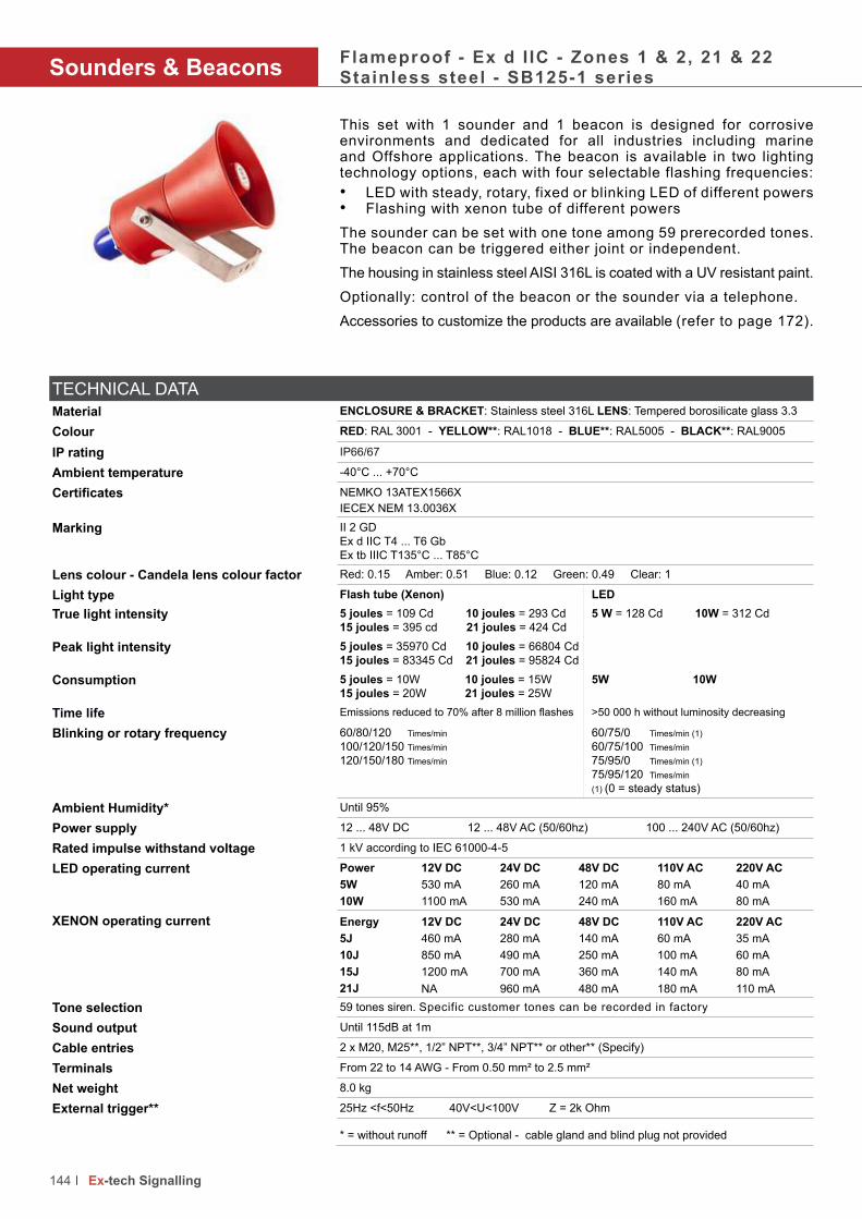
Sounders & BeaconsFlameproof - Ex d I IC - Zones 1 & 2, 21 & 22Stainless steel - SB125-1 series
This set with 1 sounder and 1 beacon is designed for corrosive environments and dedicated for all industries including marine and Offshore applications. The beacon is available in two lighting technology options, each with four selectable flashing frequencies:
• LED with steady, rotary, fixed or blinking LED of different powers• Flashing with xenon tube of different powers
The sounder can be set with one tone among 59 prerecorded tones. The beacon can be triggered either joint or independent.
The housing in stainless steel AISI 316L is coated with a UV resistant paint.
Optionally: control of the beacon or the sounder via a telephone.
Accessories to customize the products are available (refer to page 172).
144 Ex-tech Signalling
TECHNICAL DATA
Material ENCLOSURE & BRACKET: Stainless steel 316L LENS: Tempered borosilicate glass 3.3
Colour RED: RAL 3001 - YELLOW**: RAL1018 - BLUE**: RAL5005 - BLACK**: RAL9005
IP rating IP66/67
Ambient temperature -40°C ... +70°C
Certificates NEMKO 13ATEX1566XIECEX NEM 13.0036X
Marking II 2 GD
Ex d IIC T4 ... T6 Gb
Ex tb IIIC T135°C ... T85°C
Lens colour - Candela lens colour factor Red: 0.15 Amber: 0.51 Blue: 0.12 Green: 0.49 Clear: 1
Light type Flash tube (Xenon) LED
True light intensity 5 joules = 109 Cd 10 joules = 293 Cd 15 joules = 395 cd 21 joules = 424 Cd
5 W = 128 Cd 10W = 312 Cd
Peak light intensity 5 joules = 35970 Cd 10 joules = 66804 Cd 15 joules = 83345 Cd 21 joules = 95824 Cd
Consumption 5 joules = 10W 10 joules = 15W15 joules = 20W 21 joules = 25W
5W 10W
Time life Emissions reduced to 70% after 8 million flashes >50 000 h without luminosity decreasing
Blinking or rotary frequency 60/80/120 Times/min
100/120/150 Times/min
120/150/180 Times/min
60/75/0 Times/min (1)
60/75/100 Times/min
75/95/0 Times/min (1)
75/95/120 Times/min
(1) (0 = steady status)
Ambient Humidity* Until 95%
Power supply 12 ... 48V DC 12 ... 48V AC (50/60hz) 100 ... 240V AC (50/60hz)
Rated impulse withstand voltage 1 kV according to IEC 61000-4-5
LED operating current Power 12V DC 24V DC 48V DC 110V AC 220V AC
5W 530 mA 260 mA 120 mA 80 mA 40 mA
10W 1100 mA 530 mA 240 mA 160 mA 80 mA
XENON operating current Energy 12V DC 24V DC 48V DC 110V AC 220V AC
5J 460 mA 280 mA 140 mA 60 mA 35 mA
10J 850 mA 490 mA 250 mA 100 mA 60 mA
15J 1200 mA 700 mA 360 mA 140 mA 80 mA
21J NA 960 mA 480 mA 180 mA 110 mA
Tone selection 59 tones siren. Specific customer tones can be recorded in factory
Sound output Until 115dB at 1m
Cable entries 2 x M20, M25**, 1/2” NPT**, 3/4” NPT** or other** (Specify)
Terminals From 22 to 14 AWG - From 0.50 mm² to 2.5 mm²
Net weight 8.0 kg
External trigger** 25Hz <f<50Hz 40V<U<100V Z = 2k Ohm
* = without runoff ** = Optional - cable gland and blind plug not provided

• •
145Ex-tech Signalling
Meaning of lens colour usage in the international standard (IEC 60073)
Colour Meaning Action Example
RED EMERGENTDangerous state
Take immediate action
Pressure/Temperature beyond the safe state - Shutdown due to the action
of protective devices - Fire alarm - Equipment failure alarm
AMBER ABNORMALAbnormal state, near the critical
status
Pressure/Temperature above the normal range - Protective device
released - Toxic and harmful gases release alarm
GREEN SAFE Normal statePressure/Temperature in normal state - Automatic control system is
operating normally
BLUE MANDATORY Requires operator’s actionEmergency evacuation - Abandon rescue and escape - Abandon platform
or abandon ship - Enter the command
CLEARNO SPECIAL
SIGNIFICANCE
If uncertainty for other colours,
clear is allowed to be used
General information - Can’t exactly use red, yellow, green or blue - Used
for the implementation of command - Indicate the measured values
Add the codes related to the features required to SB125-1 :
Product code configuratorLens colour
R = Red
A = Amber
B = Blue
G = Green
C = Clear
Type
X=
Xenon
L=
LED
Power
05LED: 5WXenon: 5J
10LED: 10WXenon: 10J
15Xenon: 15J
21Xenon: 21J
Duty
label
Y=
Yes
N=
No
Lens
guard
Y=
Yes
N=
No
Tag
label
Y=
Yes
N=
No
Cable
entry
A
=M20
B=
M25
C=
1/2” NPT
D=
3/4” NPT
Finish colour
RD = Red
YW = Yellow
BU = Blue
BL = Black
OR = Other on request
Telephone
initiated
Y=
Yes
N=
No
Voltage
DC 12 .. 48V DC
AC1
12..48V AC
AC100 .. 240V AC
OR(Other Request)
Dimensions

Sounders & BeaconsFlameproof - Ex d I IC - Zones 1 & 2, 21 & 22Glass-reinforced polyester - SB150-1 series
This set with 1 sounder and 1 beacon is designed for corrosive environments and dedicated for all industries including marine and Offshore applications. The beacon is available in two lighting technology options, each with four selectable flashing frequencies:
• LED with steady, rotary, fixed or blinking LED of different powers• Flashing with xenon tube of different powers
The sounder can be set with one tone among 59 prerecorded tones. The beacon can be triggered either joint or independent.
The housing moulded in glass-reinforced polyester is dyed in the mass and protected with a UV resistant paint.
Optionally: control of the beacon or the sounder via a telephone.
Accessories to customize the products are available (refer to page 172).
146 Ex-tech Signalling
TECHNICAL DATA
Material ENCLOSURE: Glass-reinforced polyester (GRP) LENS: Tempered borosilicate glass 3.3BRACKET: Stainless steel AISI 316L
Colour RED: RAL 3001 - YELLOW**: RAL1018 - BLUE**: RAL5005 - BLACK**: RAL9005
IP rating IP66/67
Ambient temperature -40°C ... +70°C
Certificates NEMKO 13ATEX1566XIECEX NEM 13.0036X
Marking II 2 GD
Ex d IIC T4 ... T6 Gb
Ex tb IIIC T135°C ... T85°C
Lens colour - Candela lens colour factor Red: 0.15 Amber: 0.51 Blue: 0.12 Green: 0.49 Clear: 1
Light type Flash tube (Xenon) LED
True light intensity 5 joules = 109 Cd 10 joules = 293 Cd 15 joules = 395 cd 21 joules = 424 Cd
5 W = 128 Cd 10W = 312 Cd
Peak light intensity 5 joules = 35970 Cd 10 joules = 66804 Cd 15 joules = 83345 Cd 21 joules = 95824 Cd
Consumption 5 joules = 10W 10 joules = 15W15 joules = 20W 21 joules = 25W
5W 10W
Time life Emissions reduced to 70% after 8 million flashes >50 000 h without luminosity decreasing
Blinking or rotary frequency 60/80/120 Times/min
100/120/150 Times/min
120/150/180 Times/min
60/75/0 Times/min (1)
60/75/100 Times/min
75/95/0 Times/min (1)
75/95/120 Times/min
(1) (0 = steady status)
Ambient Humidity* Until 95%
Power supply 12 ... 48V DC 12 ... 48V AC (50/60hz) 100 ... 240V AC (50/60hz)
Rated impulse withstand voltage 1 kV according to IEC 61000-4-5
LED operating current Power 12V DC 24V DC 48V DC 110V AC 220V AC
5W 530 mA 260 mA 120 mA 80 mA 40 mA
10W 1100 mA 530 mA 240 mA 160 mA 80 mA
XENON operating current Energy 12V DC 24V DC 48V DC 110V AC 220V AC
5J 460 mA 280 mA 140 mA 60 mA 35 mA
10J 850 mA 490 mA 250 mA 100 mA 60 mA
15J 1200 mA 700 mA 360 mA 140 mA 80 mA
21J NA 960 mA 480 mA 180 mA 110 mA
Tone selection 59 tones siren. Specific customer tones can be recorded in factory
Sound output Until 115dB at 1m
Cable entries 2 x M20, M25**, 1/2” NPT**, 3/4” NPT** or other** (Specify)
Terminals From 22 to 14 AWG - From 0.50 mm² to 2.5 mm²
Net weight 6.5 kg
External trigger** 25Hz <f<50Hz 40V<U<100V Z = 2k Ohm
* = without runoff ** = Optional - cable gland and blind plug not provided
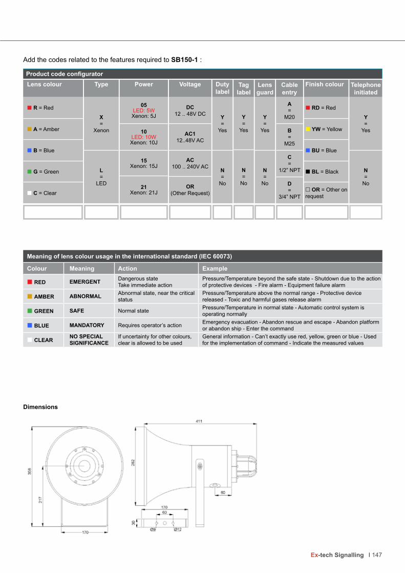
• •
147Ex-tech Signalling
Meaning of lens colour usage in the international standard (IEC 60073)
Colour Meaning Action Example
RED EMERGENTDangerous state
Take immediate action
Pressure/Temperature beyond the safe state - Shutdown due to the action
of protective devices - Fire alarm - Equipment failure alarm
AMBER ABNORMALAbnormal state, near the critical
status
Pressure/Temperature above the normal range - Protective device
released - Toxic and harmful gases release alarm
GREEN SAFE Normal statePressure/Temperature in normal state - Automatic control system is
operating normally
BLUE MANDATORY Requires operator’s actionEmergency evacuation - Abandon rescue and escape - Abandon platform
or abandon ship - Enter the command
CLEARNO SPECIAL
SIGNIFICANCE
If uncertainty for other colours,
clear is allowed to be used
General information - Can’t exactly use red, yellow, green or blue - Used
for the implementation of command - Indicate the measured values
Add the codes related to the features required to SB150-1 :
Product code configuratorLens colour
R = Red
A = Amber
B = Blue
G = Green
C = Clear
Type
X=
Xenon
L=
LED
Power
05LED: 5WXenon: 5J
10LED: 10WXenon: 10J
15Xenon: 15J
21Xenon: 21J
Duty
label
Y=
Yes
N=
No
Lens
guard
Y=
Yes
N=
No
Tag
label
Y=
Yes
N=
No
Cable
entry
A
=M20
B=
M25
C=
1/2” NPT
D=
3/4” NPT
Finish colour
RD = Red
YW = Yellow
BU = Blue
BL = Black
OR = Other on request
Telephone
initiated
Y=
Yes
N=
No
Voltage
DC 12 .. 48V DC
AC1
12..48V AC
AC100 .. 240V AC
OR(Other Request)
Dimensions

Combined productsFlameproof - Ex d I IC - Zones 1 & 2, 21 & 22Stainless steel - SB125 series
This set is designed for corrosive environments and dedicated for all industries including marine and Offshore applications. The set is provided with a sounder plus a combination of 4 products max. The beacons are available in two lighting technology options, each with four selectable flashing frequencies:
• LED with steady, rotary, fixed or blinking LED of different powers• Flashing with xenon tube of different powers
The sounder can be set with one tone among 59 prerecorded tones. The beacons can be triggered either joint or independent.
The housing in stainless steel AISI 316L is coated with a UV resistant paint.
Optionally: control of the beacon and the sounder via a telephone. One beacon can be replaced by a push button or a junction box.
Accessories to customize the products are available (refer to page 172).
148 Ex-tech Signalling
TECHNICAL DATA
Material ENCLOSURE: Stainless steel 316L LENS: Tempered borosilicate glass 3.3
MOUNTING PLATE: Stainless steel AISI 316L
Colour RED: RAL 3001 - YELLOW**: RAL1018 - BLUE**: RAL5005 - BLACK**: RAL9005
IP rating IP66/67
Ambient temperature -40°C ... +70°C
Certificates NEMKO 13ATEX1561XIECEX NEM 13.0030X
Marking II 2 GD
Ex d IIC T4 ... T6 Gb
Ex tb IIIC T135°C ... T85°C
Lens colour - Candela lens colour factor Red: 0.15 Amber: 0.51 Blue: 0.12 Green: 0.49 Clear: 1
Light type Flash tube (Xenon) LED
True light intensity 5 joules = 109 Cd 10 joules = 293 Cd 15 joules = 395 cd 21 joules = 424 Cd
5 W = 128 Cd 10W = 312 Cd
Peak light intensity 5 joules = 35970 Cd 10 joules = 66804 Cd 15 joules = 83345 Cd 21 joules = 95824 Cd
Consumption 5 joules = 10W 10 joules = 15W15 joules = 20W 21 joules = 25W
5W 10W
Time life Emissions reduced to 70% after 8 million flashes >50 000 h without luminosity decreasing
Blinking or rotary frequency 60/80/120 Times/min
100/120/150 Times/min
120/150/180 Times/min
60/75/0 Times/min (1)
60/75/100 Times/min
75/95/0 Times/min (1)
75/95/120 Times/min
(1) (0 = steady status)
Ambient Humidity* Until 95%
Power supply 12 ... 48V DC 12 ... 48V AC (50/60hz) 100 ... 240V AC (50/60hz)
Rated impulse withstand voltage 1 kV according to IEC 61000-4-5
LED operating current Power 12V DC 24V DC 48V DC 110V AC 220V AC
5W 530 mA 260 mA 120 mA 80 mA 40 mA
10W 1100 mA 530 mA 240 mA 160 mA 80 mA
XENON operating current Energy 12V DC 24V DC 48V DC 110V AC 220V AC
5J 460 mA 280 mA 140 mA 60 mA 35 mA
10J 850 mA 490 mA 250 mA 100 mA 60 mA
15J 1200 mA 700 mA 360 mA 140 mA 80 mA
21J NA 960 mA 480 mA 180 mA 110 mA
Tone selection 59 tones siren. Specific customer tones can be recorded in factory
Sound output Until 115dB at 1m
Cable entries 3 x M20, M25**, 1/2” NPT**, 3/4” NPT** or other** (Specify)
Terminals From 22 to 14 AWG - From 0.50 mm² to 2.5 mm²
Net weight SB125-2 : 11.9 kg - SB125-3 : 16.7 kg - SB125-4 : 20.7 kg - SB125-5 : 25.10 kg
External trigger** 25Hz <f<50Hz 40V<U<100V Z = 2k Ohm
* = without runoff ** = Optional - cable gland and blind plug not provided

• •
149Ex-tech Signalling
Add the codes related to the features required to SB125:
Product code configuratorLens
guard
Y=
Yes
N=
No
Tag
label
Y=
Yes
N=
No
Cable
entry
A
=M20
B=
M25
C=
1/2” NPT
D=
3/4” NPT
Finish
colour
RD = Red
YW = Yellow
BU = Blue
BL = Black
OR = Other on request
Tel.
init.
Y=
Yes
N=
No
Meaning of lens colour usage in the international standard (IEC 60073)
Colour Meaning Action Example
RED EMERGENTDangerous state
Take immediate action
Pressure/Temperature beyond the safe state - Shutdown due to the action
of protective devices - Fire alarm - Equipment failure alarm
AMBER ABNORMALAbnormal state, near the critical
status
Pressure/Temperature above the normal range - Protective device
released - Toxic and harmful gases release alarm
GREEN SAFE Normal statePressure/Temperature in normal state - Automatic control system is
operating normally
BLUE MANDATORY Requires operator’s actionEmergency evacuation - Abandon rescue and escape - Abandon platform
or abandon ship - Enter the command
CLEARNO SPECIAL
SIGNIFICANCE
If uncertainty for other colours,
clear is allowed to be used
General information - Can’t exactly use red, yellow, green or blue - Used
for the implementation of command - Indicate the measured values
Dimensions
Duty
label
Y=
Yes
N=
No
Power
05LED: 5WXenon: 5J
10LED: 10WXenon: 10J
15Xenon: 15J
21Xenon: 21J
Voltage
DC 12 .. 48V DC
AC1
12..48V AC
AC100 .. 240V AC
OR(Other Request)
Combination type
2J/P - 1 Sounder, 1 Beacon with Junction Box or Push Button
3J/P - 1 Sounder,2 Beacons with Junction Box or Push Button
4J/P - 1 Sounder, 3 Beacons with Junction Box or Push Button
O - Other combinations
Type
X=
Xenon
L=
LED
Lens colour
R = Red
A = Amber
B = Blue
G = Green
C = Clear

Combined productsFlameproof - Ex d I IC - Zones 1 & 2, 21 & 22Glass-reinforced polyester - SB150 series
This set is designed for corrosive environments and dedicated for all industries including marine and Offshore applications. The set is provided with a sounder plus a combination of 4 products max. The beacons are available in two lighting technology options, each with four selectable flashing frequencies:
• LED with steady, rotary, fixed or blinking LED of different powers• Flashing with xenon tube of different powers
The sounder can be set with one tone among 59 prerecorded tones. The beacons can be triggered either joint or independent.
The housing moulded in glass-reinforced polyester is dyed in the mass and protected with a UV resistant paint.
Optionally: control of the beacons and the sounder via a telephone. One beacon can be replaced by a push button or a junction box.
Accessories to customize the products are available (refer to page 172).
150 Ex-tech Signalling
TECHNICAL DATA
Material ENCLOSURE: Glass-reinforced polyester (GRP) LENS: Tempered borosilicate glass 3.3
MOUNTING PLATE: Stainless steel AISI 316L
Colour RED: RAL 3001 - YELLOW**: RAL1018 - BLUE**: RAL5005 - BLACK**: RAL9005
IP rating IP66/67
Ambient temperature -40°C ... +70°C
Certificates NEMKO 13 ATEX 1566XIECEX NEM 13.0036X
Marking II 2 GD
Ex d IIC T4 ... T6 Gb
Ex tb IIIC T135°C ... T85°C
Lens colour - Candela lens colour factor Red: 0.15 Amber: 0.51 Blue: 0.12 Green: 0.49 Clear: 1
Light type Flash tube (Xenon) LED
True light intensity 5 joules = 109 Cd 10 joules = 293 Cd 15 joules = 395 cd 21 joules = 424 Cd
5 W = 128 Cd 10W = 312 Cd
Peak light intensity 5 joules = 35970 Cd 10 joules = 66804 Cd 15 joules = 83345 Cd 21 joules = 95824 Cd
Consumption 5 joules = 10W 10 joules = 15W15 joules = 20W 21 joules = 25W
5W 10W
Time life Emissions reduced to 70% after 8 million flashes >50 000 h without luminosity decreasing
Blinking or rotary frequency 60/80/120 Times/min
100/120/150 Times/min
120/150/180 Times/min
60/75/0 Times/min (1)
60/75/100 Times/min
75/95/0 Times/min (1)
75/95/120 Times/min
(1) (0 = steady status)
Ambient Humidity* Until 95%
Power supply 12 ... 48V DC 12 ... 48V AC (50/60hz) 100 ... 240V AC (50/60hz)
Rated impulse withstand voltage 1 kV according to IEC 61000-4-5
LED operating current Power 12V DC 24V DC 48V DC 110V AC 220V AC
5W 530 mA 260 mA 120 mA 80 mA 40 mA
10W 1100 mA 530 mA 240 mA 160 mA 80 mA
XENON operating current Energy 12V DC 24V DC 48V DC 110V AC 220V AC
5J 460 mA 280 mA 140 mA 60 mA 35 mA
10J 850 mA 490 mA 250 mA 100 mA 60 mA
15J 1200 mA 700 mA 360 mA 140 mA 80 mA
21J NA 960 mA 480 mA 180 mA 110 mA
Tone selection 59 tones siren. Specific customer tones can be recorded in factory
Sound output Until 115dB at 1m
Cable entries 3 x M20, M25**, 1/2” NPT**, 3/4” NPT** or other** (Specify)
Terminals From 22 to 14 AWG - From 0.50 mm² to 2.5 mm²
Net weight SB150-2 : 10.4 kg - SB150-3 : 14.5 kg - SB150-4 : 18.5 kg - SB150-5 : 22.1 kg
External trigger** 25Hz <f<50Hz 40V<U<100V Z = 2k Ohm
* = without runoff ** = Optional - cable gland and blind plug not provided
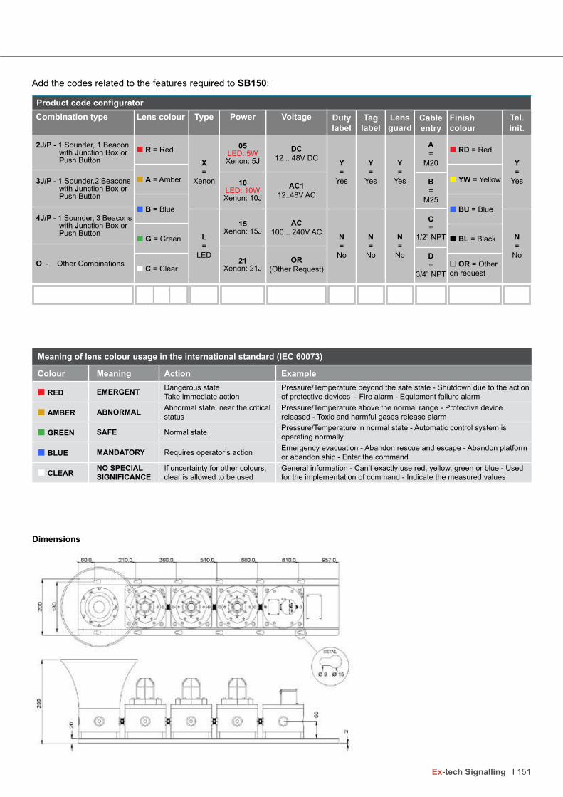
• •
151Ex-tech Signalling
Add the codes related to the features required to SB150:
Meaning of lens colour usage in the international standard (IEC 60073)
Colour Meaning Action Example
RED EMERGENTDangerous state
Take immediate action
Pressure/Temperature beyond the safe state - Shutdown due to the action
of protective devices - Fire alarm - Equipment failure alarm
AMBER ABNORMALAbnormal state, near the critical
status
Pressure/Temperature above the normal range - Protective device
released - Toxic and harmful gases release alarm
GREEN SAFE Normal statePressure/Temperature in normal state - Automatic control system is
operating normally
BLUE MANDATORY Requires operator’s actionEmergency evacuation - Abandon rescue and escape - Abandon platform
or abandon ship - Enter the command
CLEARNO SPECIAL
SIGNIFICANCE
If uncertainty for other colours,
clear is allowed to be used
General information - Can’t exactly use red, yellow, green or blue - Used
for the implementation of command - Indicate the measured values
Dimensions
Product code configurator
Duty
label
Y=
Yes
N=
No
Lens
guard
Y=
Yes
N=
No
Tag
label
Y=
Yes
N=
No
Finish
colour
RD = Red
YW = Yellow
BU = Blue
BL = Black
OR = Other on request
Power
05LED: 5WXenon: 5J
10LED: 10WXenon: 10J
15Xenon: 15J
21Xenon: 21J
Combination type
2J/P - 1 Sounder, 1 Beacon with Junction Box or Push Button
3J/P - 1 Sounder,2 Beacons with Junction Box or Push Button
4J/P - 1 Sounder, 3 Beacons with Junction Box or Push Button
O - Other Combinations
Type
X=
Xenon
L=
LED
Tel.
init.
Y=
Yes
N=
No
Voltage
DC 12 .. 48V DC
AC1
12..48V AC
AC100 .. 240V AC
OR(Other Request)
Lens colour
R = Red
A = Amber
B = Blue
G = Green
C = Clear
Cable
entry
A
=M20
B=
M25
C=
1/2” NPT
D=
3/4” NPT

Status lightsFlameproof - Ex d I IC - Zones 1 & 2, 21 & 22Stainless Steel - SL125 series
This set is designed for corrosive environments and dedicated for all industries including marine and Offshore applications. The set is provided with a sounder and 4 beacons max. The beacons are available in two lighting technology options, each with four selectable flashing frequencies:
• LED with steady, rotary, fixed or blinking LED of different powers• Flashing with xenon tube of different powers
The beacons can be triggered either joint or independently.
The housing in stainless steel AISI 316L is coated with a UV resistant paint.
Optionally : control of all beacons or individually via a telephone line. One beacon can be replaced by a push button or a junction box.
Accessories to customize the products are available (refer to page 172).
152 Ex-tech Signalling
TECHNICAL DATA
Material ENCLOSURE: Stainless steel AISI 316L LENS: Tempered borosilicate glass 3.3
MOUNTING PLATE: Stainless steel AISI 316L
Colour RED: RAL 3001 - YELLOW**: RAL1018 - BLUE**: RAL5005 - BLACK**: RAL9005
IP rating IP66/67
Ambient temperature -40°C ... +70°C
Certificates NEMKO 13ATEX1565XIECEX NEM 13.0035X
Marking II 2 GD
Ex d IIC T4 ... T6 Gb
Ex tb IIIC T135°C ... T85°C
Lens colour - Candela lens colour factor Red: 0.15 Amber: 0.51 Blue: 0.12 Green: 0.49 Clear: 1
Light type Flash tube (Xenon) LED
True light intensity 5 joules = 109 Cd 10 joules = 293 Cd 15 joules = 395 cd 21 joules = 424 Cd
5 W = 128 Cd 10W = 312 Cd
Peak light intensity 5 joules = 35970 Cd 10 joules = 66804 Cd 15 joules = 83345 Cd 21 joules = 95824 Cd
Consumption 5 joules = 10W 10 joules = 15W15 joules = 20W 21 joules = 25W
5W 10W
Time life Emissions reduced to 70% after 8 million flashes >50 000 h without luminosity decreasing
Blinking or rotary frequency 60/80/120 Times/min
100/120/150 Times/min
120/150/180 Times/min
60/75/0 Times/min (1)
60/75/100 Times/min
75/95/0 Times/min (1)
75/95/120 Times/min
(1) (0 = steady status)
Ambient Humidity* Until 95%
Power supply 12 ... 48V DC 12 ... 48V AC (50/60hz) 100 ... 240V AC (50/60hz)
Rated impulse withstand voltage 1 kV according to IEC 61000-4-5
LED operating current Power 12V DC 24V DC 48V DC 110V AC 220V AC
5W 530 mA 260 mA 120 mA 80 mA 40 mA
10W 1100 mA 530 mA 240 mA 160 mA 80 mA
XENON operating current Energy 12V DC 24V DC 48V DC 110V AC 220V AC
5J 460 mA 280 mA 140 mA 60 mA 35 mA
10J 850 mA 490 mA 250 mA 100 mA 60 mA
15J 1200 mA 700 mA 360 mA 140 mA 80 mA
21J NA 960 mA 480 mA 180 mA 110 mA
Cable entries 3 x M20, M25**, 1/2” NPT**, 3/4” NPT** or other** (Specify)
Terminals From 22 to 14 AWG - From 0.50 mm² to 2.5 mm²
Net weight SL125-2: 10.2 kg - SL125-3: 15.0 kg - SL125-4: 20.0 kg - SL125-5: 24.5 kg
External trigger** 25Hz <f<50Hz 40V<U<100V Z = 2k Ohm
* = without runoff ** = Optional - cable gland and blind plug not provided

• •
153Ex-tech Signalling
Add the codes related to the features required to SL125:
Product code configurator
Meaning of lens colour usage in the international standard (IEC 60073)
Colour Meaning Action Example
RED EMERGENTDangerous state
Take immediate action
Pressure/Temperature beyond the safe state - Shutdown due to the action
of protective devices - Fire alarm - Equipment failure alarm
AMBER ABNORMALAbnormal state, near the critical
status
Pressure/Temperature above the normal range - Protective device
released - Toxic and harmful gases release alarm
GREEN SAFE Normal statePressure/Temperature in normal state - Automatic control system is
operating normally
BLUE MANDATORY Requires operator’s actionEmergency evacuation - Abandon rescue and escape - Abandon platform
or abandon ship - Enter the command
CLEARNO SPECIAL
SIGNIFICANCE
If uncertainty for other colours,
clear is allowed to be used
General information - Can’t exactly use red, yellow, green or blue - Used
for the implementation of command - Indicate the measured values
Dimensions
Duty
label
Y=
Yes
N=
No
Lens
guard
Y=
Yes
N=
No
Tag
label
Y=
Yes
N=
No
Cable
entry
A
=M20
B=
M25
C=
1/2” NPT
D=
3/4” NPT
Finish colour
RD = Red
YW = Yellow
BU = Blue
BL = Black
Power
05LED: 5WXenon: 5J
10LED: 10WXenon: 10J
15Xenon: 15J
21Xenon: 21J
Combination type
A20 - 2 Beacons
B30 - 3 Beacons
B3J - 2 Beacons & 1 Junction Box
B3P - 2 Beacons & 1 Push Button
C40 - 4 Beacons
C4J - 3 Beacons & 1 Junction Box
C4P - 3 Beacons & 1 Push Button
D50 - 5 Beacons
D5J - 4 Beacons & 1 Junction Box
D5P - 4 Beacons & 1 Push Button
Type
X=
Xenon
L=
LED
Tel.
init.
Y=
Yes
N=
No
Voltage
DC 12 .. 48V DC
AC1
12..48V AC
AC100 .. 240V AC
OR(Other Request)
Lens colour
R = Red
A = Amber
B = Blue
G = Green
C = Clear

Status lightsFlameproof - Ex d I IC - Zones 1 & 2, 21 & 22Glass-reinforced polyester - SL150 series
This set is designed for corrosive environments and dedicated for all industries including marine and Offshore applications. The set is provided with a sounder and 4 beacons max. The beacons are available in two lighting technology options, each with four selectable flashing frequencies:
• LED with steady, rotary, fixed or blinking LED of different powers• Flashing with xenon tube of different powers
The beacons can be triggered either joint or independently.
The housing moulded in glass-reinforced polyester is dyed in the mass and protected with a UV resistant paint.
Optionally : control of all beacons or individually via a telephone line. One beacon can be replaced by a push button or a junction box.
Accessories to customize the products are available (refer to page 172).
154 Ex-tech Signalling
TECHNICAL DATA
Material ENCLOSURE: Glass-reinforced polyester (GRP) LENS: Tempered borosilicate glass 3.3
MOUNTING PLATE: Stainless steel AISI 316L
Colour RED: RAL 3001 - YELLOW**: RAL1018 - BLUE**: RAL5005 - BLACK**: RAL9005
IP rating IP66/67
Ambient temperature -40°C ... +70°C
Certificates NEMKO 13ATEX1565XIECEX NEM 13.0035X
Marking II 2 GD
Ex d IIC T4 ... T6 Gb
Ex tb IIIC T135°C ... T85°C
Lens colour - Candela lens colour factor Red: 0.15 Amber: 0.51 Blue: 0.12 Green: 0.49 Clear: 1
Light type Flash tube (Xenon) LED
True light intensity 5 joules = 109 Cd 10 joules = 293 Cd 15 joules = 395 cd 21 joules = 424 Cd
5 W = 128 Cd 10W = 312 Cd
Peak light intensity 5 joules = 35970 Cd 10 joules = 66804 Cd 15 joules = 83345 Cd 21 joules = 95824 Cd
Consumption 5 joules = 10W 10 joules = 15W15 joules = 20W 21 joules = 25W
5W 10W
Time life Emissions reduced to 70% after 8 million flashes >50 000 h without luminosity decreasing
Blinking or rotary frequency 60/80/120 Times/min
100/120/150 Times/min
120/150/180 Times/min
60/75/0 Times/min (1)
60/75/100 Times/min
75/95/0 Times/min (1)
75/95/120 Times/min
(1) (0 = steady status)
Ambient Humidity* Until 95%
Power supply 12 ... 48V DC 12 ... 48V AC (50/60hz) 100 ... 240V AC (50/60hz)
Rated impulse withstand voltage 1 kV according to IEC 61000-4-5
LED operating current Power 12V DC 24V DC 48V DC 110V AC 220V AC
5W 530 mA 260 mA 120 mA 80 mA 40 mA
10W 1100 mA 530 mA 240 mA 160 mA 80 mA
XENON operating current Energy 12V DC 24V DC 48V DC 110V AC 220V AC
5J 460 mA 280 mA 140 mA 60 mA 35 mA
10J 850 mA 490 mA 250 mA 100 mA 60 mA
15J 1200 mA 700 mA 360 mA 140 mA 80 mA
21J NA 960 mA 480 mA 180 mA 110 mA
Cable entries 3 x M20, M25**, 1/2” NPT**, 3/4” NPT** or other** (Specify)
Terminals From 22 to 14 AWG - From 0.50 mm² to 2.5 mm²
Net weight SL150-2: 10.2 kg - SL150-3: 15.2 kg - SL150-4: 20.2 kg - SL150-5: 23.9 kg
External trigger** 25Hz <f<50Hz 40V<U<100V Z = 2k Ohm
* = without runoff ** = Optional - cable gland and blind plug not provided

• •
155Ex-tech Signalling
Add the codes related to the features required to SL150:
Meaning of lens colour usage in the international standard (IEC 60073)
Colour Meaning Action Example
RED EMERGENTDangerous state
Take immediate action
Pressure/Temperature beyond the safe state - Shutdown due to the action
of protective devices - Fire alarm - Equipment failure alarm
AMBER ABNORMALAbnormal state, near the critical
status
Pressure/Temperature above the normal range - Protective device
released - Toxic and harmful gases release alarm
GREEN SAFE Normal statePressure/Temperature in normal state - Automatic control system is
operating normally
BLUE MANDATORY Requires operator’s actionEmergency evacuation - Abandon rescue and escape - Abandon platform
or abandon ship - Enter the command
CLEARNO SPECIAL
SIGNIFICANCE
If uncertainty for other colours,
clear is allowed to be used
General information - Can’t exactly use red, yellow, green or blue - Used
for the implementation of command - Indicate the measured values
Product code configurator
Dimensions
Duty
label
Y=
Yes
N=
No
Lens
guard
Y=
Yes
N=
No
Tag
label
Y=
Yes
N=
No
Cable
entry
A
=M20
B=
M25
C=
1/2” NPT
D=
3/4” NPT
Finish colour
RD = Red
YW = Yellow
BU = Blue
BL = Black
Power
05LED: 5WXenon: 5J
10LED: 10WXenon: 10J
15Xenon: 15J
21Xenon: 21J
Combination type
A20 - 2 Beacons
B30 - 3 Beacons
B3J - 2 Beacons &1 Junction Box
B3P - 2 Beacons & 1 Push Button
C40 - 4 Beacons
C4J - 3 Beacons &1 Junction Box
C4P - 3 Beacons & 1 Push Button
D50 - 5 Beacons
D5J - 4 Beacons &1 Junction Box
D5P - 4 Beacons & 1 Push Button
Type
X=
Xenon
L=
LED
Tel.
init.
Y=
Yes
N=
No
Voltage
DC 12 .. 48V DC
AC1
12..48V AC
AC100 .. 240V AC
OR(Other Request)
Lens colour
R = Red
A = Amber
B = Blue
G = Green
C = Clear

Manual call pointsFlameproof - Ex d I IC - Zones 1 & 2, 21 & 22Stainless Steel - CP125 series
This manual call point “break glass” type is designed for corrosive environments and dedicated for the Oil & Gas, chemical, petrochemical, pharmacy industries, marine and offshore applications.
The product is compatible with PLC, ESD, DCS systems via an output 4-20mA.
The housing in stainless steel AISI 316L is coated with a UV resistant paint.
Optionally: visualisation functions, line detection, glass protection and hammer.
Accessories to customize the products are available (refer to page 172).
156 Ex-tech Signalling
TECHNICAL DATA
Material ENCLOSURE: Stainless steel AISI 316 L
Colour RED: RAL 3001 - YELLOW**: RAL1018 - BLUE**: RAL5005 - BLACK**: RAL9005
IP rating IP66/67
Ambient temperature -40°C ... +70°C
CertificatesNEMKO 13ATEX1563XIECEX NEM 13.0033X
Marking II 2 GD
Ex d IIC T6 Gb
Ex tb IIIC T85°C (Tamb = -40°C ... +70°C)
Ambient humidity* Until 95% with ice*
Rated impulse withstand voltage 1kV according to IEC 61000-4-5
Contact type 1x C/O or 2 x C/O**
Conventional thermal courant (lth) AC 125/250V (50/60Hz)=11A*** ; 30V DC= 6A*** ; 125V DC = 0.3A***
Minimum voltage and courant DC 5V 10mA
Shorts circuit protection 10 A gG
Cable entries 4 x M20, M25**, 1/2” NPT**, 3/4” NPT** or other** (Specify)
Terminals From 22 to 14 AWG - From 0.5mm² to 2.5mm²
Net Weight 4.9 Kg
Line resistor** 470 Ohm**
Signalling LED** Green U=24V DC I= 10mA ; Red U=24V DC I= 20mA
* = without runoff - ** = optional - *** = resistive load - cable gland and blind plug not provided

157Ex-tech Signalling
Add the codes related to the features required to CP125:
Duty label
Y=
Yes
N=
No
Cable entry
A
=M20
B=
M25
C=
1/2” NPT
D=
3/4” NPT
Finish colour
RD = Red
YW = Yellow
BU = Blue
BL = Black
OR = Other on request
Tag label
Y=
Yes
N=
No
Features
F = Lift Flap
R = Resistor
D = Diode
N = No features
LED Indicator
L = Red & Green
R = Red
G = Green
N = No LED
Switch
Single = 1 x C/O
Double = 2 x C/O
Product code configurator
Dimensions

Manual call pointsFlameproof - Ex d I IB+H2 - Zones 1 & 2, 21 & 22 Glass-reinforced polyester - CP135 series
This manual call point “break glass” type is designed for corrosive environments and dedicated for the Oil & Gas, chemical, petrochemical, pharmacy industries, marine and offshore applications.
The product is compatible with PLC, ESD, DCS systems via an output 4-20mA.
The housing moulded in glass-reinforced polyester is dyed in the mass and protected with a UV resistant paint.
Optionally: visualisation functions, line detection, glass protection and hammer.
Accessories to customize the products are available (refer to page 172).
158 Ex-tech Signalling
TECHNICAL DATA
Material ENCLOSURE: Glass-reinforced polyester (GRP)
Colour RED: RAL 3001 - YELLOW**: RAL1018 - BLUE**: RAL5005 - BLACK**: RAL9005 BLACK WITH YELLOW ZEBRA**
IP rating IP66/67
Ambient temperature -40°C ... +70°C
Certificates NEMKO 13ATEX1568XIECEX NEM 13.0038X
Marking II 2 GD
Ex d IIB+H2 T6 Gb
Ex tb IIIC T85°C (Tamb = -40°C ... +70°C)
Ambient humidity* Until 95% with ice
Rated impulse withstand voltage 1 kV according to IEC 61000-4-5
Contact type 1x C/O or 2 x C/O**
Conventional thermal courant (lth) AC 125/250V (50/60Hz)=11A*** ; 30V DC= 6A*** ; 125V DC = 0.3A***
Minimum voltage and courant DC 5V 10mA
Shorts circuit protection 10 A gG
Cable entries 2 x M20, M25**, 1/2” NPT**, 3/4” NPT** or other** (Specify)
Terminals From 22 to 14 AWG - From 0.5mm² to 2.5mm²
Net Weight 1.5 kg
Line resistor** 470 Ohm
Signalling LED** Green U=24V DC I= 10mA ; Red U=24V DC I= 20mA
* = without runoff - ** = optional - *** = resistive load - cable gland and blind plug not provided

159Ex-tech Signalling
Product code configuratorCable
entry
A
=M20
B=
M25
C=
1/2” NPT
D=
3/4” NPT
Finish colour
RD = Red
YW = Yellow
BU = Blue
BL = Black
OR = Other on request
Entry
position
T=
TOP
B=
BOTTOM
Duty label
Y=
Yes
N=
No
Switch
S = Single Switch
D = Double Switch
Tag label
Y=
Yes
N=
No
Features
F = Lift Flap
R = Resistor
D = Diode
N = No features
LED Indicator
L = Red & Green
R = Red
G = Green
N = No LED
Add the codes related to the features required to CP135:
Dimensions

Manual call pointsFlameproof - Ex d I IC - Zones 1 & 2, 21 & 22Glass-reinforced polyester - CP150 series
This manual call point “break glass” type is designed for corrosive environments and dedicated for the Oil & Gas, chemical, petrochemical, pharmacy industries, marine and offshore applications.
The product is compatible with PLC, ESD, DCS systems via an output 4-20mA.
The housing moulded in glass-reinforced polyester is dyed in the mass and protected with a UV resistant paint.
Optionally: visualisation functions, line detection, glass protection and hammer.
Accessories to customize the products are available (refer to page 172).
160 Ex-tech Signalling
TECHNICAL DATA
Material ENCLOSURE: Glass-reinforced polyester (GRP)
Colour RED: RAL 3001 - YELLOW**: RAL1018 - BLUE**: RAL5005 - BLACK**: RAL9005
IP rating IP66/67
Ambient temperature -40°C ... +70°C
CertificatesNEMKO 13ATEX1564XIECEX NEM 13.0034X
Marking II 2 GD
Ex d IIC T6 Gb
Ex tb IIIC T85°C (Tamb = -40°C ... +70°C)
Ambient humidity* Until 95% with ice
Rated impulse withstand voltage 1 kV according to IEC 61000-4-5
Contact type 1x C/O or 2 x C/O**
Conventional thermal courant (lth) AC 125/250V (50/60Hz)=11A*** ; 30V DC= 6A*** ; 125V DC = 0.3A***
Minimum voltage and courant DC 5V 10mA
Shorts circuit protection 10 A gG
Cable entries 4 x M20, M25**, 1/2” NPT**, 3/4” NPT** or other** (Specify)
Terminals From 22 to 14 AWG - From 0.5mm² to 2.5mm²
Net Weight 4.2 kg
Line resistor** 470 Ohm
Signalling LED** Green U=24V DC I= 10mA ; Red U=24V DC I= 20mA
* = without runoff - ** = optional - *** = resistive load - cable gland and blind plug not provided

161Ex-tech Signalling
Add the codes related to the features required to CP150:
Product code configuratorDuty
label
Y=
Yes
N=
No
Cable entry
A
=M20
B=
M25
C=
1/2” NPT
D=
3/4” NPT
Finish colour
RD = Red
YW = Yellow
BU = Blue
BL = Black
OR = Other on request
Switch
Single = 1 x C/O
Double = 2 x C/0
Features
F = Lift Flap
R = Resistor
D = Diode
N = No features
Tag
label
Y=
Yes
N=
No
LED Indicator
L = Red & Green
R = Red
G = Green
N = No LED
Dimensions

Push buttonsFlameproof - Ex d I IC - Zones 1 & 2, 21 & 22Stainless Steel - PB125 series
This manual call point “push button” type is designed for corrosive environments and dedicated for the Oil & Gas, chemical, petrochemical, pharmacy industries, marine and offshore applications.
This product is compatible with PLC, ESD, DCS systems via an output 4-20mA.
There are two versions: push button and push button with key to release.
The housing in stainless steel AISI 316L is coated with a UV resistant paint.
Optionally: visualisation functions, line detection and lift flap protection.
Accessories to customize the products are available (refer to page 172).
162 Ex-tech Signalling
TECHNICAL DATA
Material ENCLOSURE: Stainless steel AISI 316L
Colour RED: RAL 3001 - YELLOW**: RAL1018 - BLUE**: RAL5005 - BLACK**: RAL9005
IP rating IP66/67
Ambient temperature -40°C ... +70°C
Certificates NEMKO 13ATEX1563XIECEX NEM 13.0033X
Marking II 2 GD
Ex d IIC T6 GbEx tb IIIC T85°C (Tamb = -40°C ... +70°C)
Ambient humidity* Until 95%, with ice if flap option
Rated impulse withstand voltage 1 kV according to IEC 61000-4-5
Contact type 1x C/O or 2 x C/O**
Unit type command Self reset or key to reset
Conventional thermal courant (lth) AC 125/250V (50/60Hz)=11A*** ; 30V DC= 6A*** ; 125V DC = 0.3A***
Minimum voltage and courant DC 5V 10mA
Shorts circuit protection 10 A gG
Cable entries 4 x M20, M25**, 1/2” NPT**, 3/4” NPT** or other** (Specify)
Terminals From 22 to 14 AWG - From 0.5mm² to 2.5mm²
Net weight 4.9 kg
Line resistor** 470 Ohm
Signalling LED** Green U=24V DC I= 10mA ; Red U=24V DC I= 20mA
* = without runoff - ** = optional *** = resistive load - cable gland and blind plug not provided

Optionally: visualisation functions, line detection and lift flap protection.
163Ex-tech Signalling
Add the codes related to the features required to PB125:
Product code configuratorDuty
label
Y=
Yes
N=
No
Cable entry
A
=M20
B=
M25
C=
1/2” NPT
D=
3/4” NPT
Finish colour
RD = Red
YW = Yellow
BU = Blue
BL = Black
OR = Other on request
Switch
S = Single Switch
D =Double Switch
Features
F = Lift Flap
R = Resistor
D = Diode
N = No features
Reset
S=
Self Reset
K=
Key Reset
Tag
label
Y=
Yes
N=
No
LED Indicator
L = Red & Green
R = Red
G = Green
N = No LED
Dimensions

Push buttonsFlameproof - Ex d I IB+H2 - Zones 1 & 2, 21 & 22 Glass-reinforced polyester - PB135 series
This manual call point “push button” type is designed for corrosive environments and dedicated for the Oil & Gas, chemical, petrochemical, pharmacy industries, marine and offshore applications.
This product is compatible with PLC, ESD, DCS systems via an output 4-20mA.
There are two versions: push button and push button with key to release.
The housing moulded in glass-reinforced polyester is dyed in the mass and protected with a UV resistant paint.
Optionally: visualisation functions, line detection and lift flap protection.
Accessories to customize the products are available (refer to page 172).
164 Ex-tech Signalling
TECHNICAL DATA
Material ENCLOSURE: Glass-reinforced polyester (GRP)
Colour RED: RAL 3001 - YELLOW**: RAL1018 - BLUE**: RAL5005 - BLACK**: RAL9005 BLACK WITH YELLOW ZEBRA**
IP rating IP66/67
Ambient temperature -40°C ... +70°C
Certificates NEMKO 13ATEX1563XIECEX NEM 13.0033X
Marking II 2 GD
Ex d IIB+H2 T6GbEx tb IIIC T85°C (Tamb = -40°C ... +70°C)
Ambient humidity* Until 95%, with ice if flap option
Rated impulse withstand voltage 1kV according to IEC 61000-4-5
Contact type 1x C/O
Unit type command self reset or key to reset
Conventional thermal courant (lth) AC 125/250V (50/60Hz)=11A*** ; 30V DC= 6A*** ; 125V DC = 0.3A***
Minimum voltage and courant DC 5V 10mA
Shorts circuit protection 10 A gG
Cable entries 2 x M20, M25**, 1/2” NPT**, 3/4” NPT** or other** (Specify)
Terminals From 22 to 14 AWG - From 0.5mm² to 2.5mm²
Net weight 2.0 kg
Line resistor** 470 Ohm
Signalling LED** Green U=24V DC I= 10mA ; Red U=24V DC I= 20mA
* = without runoff - ** = optional - *** = resistive load - cable gland and blind plug not provided

Optionally: visualisation functions, line detection and lift flap protection.
165Ex-tech Signalling
Product code configuratorDuty
label
Y=
Yes
N=
No
Cable
entry
A
=M20
B=
M25
C=
1/2” NPT
D=
3/4” NPT
Finish colour
RD = Red
YW = Yellow
BU = Blue
BL = Black
OR = Other on request
Entry
position
T=
TOP
B=
BOTTOM
Switch
S = Single Switch
Features
F = Lift Flap
R = Resistor
D = Diode
N = No features
LED Indicator
L = Red & Green
R = Red
G = Green
N = No LED
Reset
S=
Self Reset
K=
Key Reset
Tag
label
Y=
Yes
N=
No
Add the codes related to the features required to PB135 :
Dimensions

Push buttonsFlameproof - Ex d I IC - Zones 1 & 2, 21 & 22Glass-reinforced polyester - PB150 series
This manual call point “push button” type is designed for corrosive environments and dedicated for the Oil & Gas, chemical, petrochemical, pharmacy industries, marine and offshore applications.
This product is compatible with PLC, ESD, DCS systems via an output 4-20mA.
There are two versions: push button and push button with key to release.
The housing moulded in glass-reinforced polyester is dyed in the mass and protected with a UV resistant paint.
Optionally: visualisation functions, line detection and lift flap protection.
Accessories to customize the products are available (refer to page 172).
166 Ex-tech Signalling
TECHNICAL DATA
Material ENCLOSURE: Glass-reinforced polyester (GRP)
Colour RED: RAL 3001 - YELLOW**: RAL1018 - BLUE**: RAL5005 - BLACK**: RAL9005
IP rating IP66/67
Ambient temperature -40°C to +70°C
Certificates NEMKO 13ATEX1564XIECEX NEM 13.0034X
Marking II 2 GD
Ex d IIC T6 GbEx tb IIIC T85°C (Tamb = -40°C ... +70°C)
Ambient humidity* Until 95%, with ice if flap option
Rated impulse withstand voltage 1kV according to IEC 61000-4-5
Contact type 1x C/O or 2 x C/O**
Unit type command self reset or key to reset
Conventional thermal courant (lth) AC 125/250V (50/60Hz)=11A*** ; 30V DC= 6A*** ; 125V DC = 0.3A***
Minimum voltage and courant DC 5V 10mA
Shorts circuit protection 10 A gG
Cable entries 4 x M20, M25**, 1/2” NPT**, 3/4” NPT** or other** (Specify)
Terminals From 22 to 14 AWG - From 0.5mm² to 2.5mm²
Net weight 4.2 kg
Line resistor** 470 Ohm
Signalling LED** Green U=24V DC I= 10mA ; Red U=24V DC I= 20mA
* = without runoff - ** = optional- *** = resistive load - cable gland and blind plug not provided

Optionally: visualisation functions, line detection and lift flap protection.
167Ex-tech Signalling
Product code configuratorDuty
label
Y=
Yes
N=
No
Cable entry
A
=M20
B=
M25
C=
1/2” NPT
D=
3/4” NPT
Finish colour
RD = Red
YW = Yellow
BU = Blue
BL = Black
OR = Other on request
Switch
S = Single Switch
D =Double Switch
Features
F = Lift Flap
R = Resistor
D = Diode
N = No features
Reset
S=
Self Reset
K=
Key Reset
Tag
label
Y=
Yes
N=
No
LED Indicator
L = Red & Green
R = Red
G = Green
N = No LED
Add the codes related to the features required to PB150 :
Dimensions

Junction boxesFlameproof - Ex d I IC - Zones 1 & 2, 21 & 22Stainless Steel - JB125 series
This junction box is designed for corrosive environments and dedicated for the Oil & Gas, chemical, petrochemical, pharmacy industries, marine and offshore applications.
The box is equipped with terminals.
The housing in stainless steel AISI 316L is coated with a UV resistant paint.
Accessories to customize the products are available (refer to page 172).
168 Ex-tech Signalling
TECHNICAL DATA
Material ENCLOSURE: Stainless steel AISI 316L
Colour RED: RAL 3001 - YELLOW**: RAL1018 - BLUE**: RAL5005 - BLACK**: RAL9005
IP rating IP66/67
Ambient temperature -40°C ... +70°C
Certificates NEMKO 13ATEX1569XIECEX NEM 13.0039X
Marking II 2 GD
Ex d IIC T4 ... T6 Gb
Ex tb IIIC T135°C ... T85°C
Ambient humidity* Until 95%
Cable entries 4 x M20, M25**, 1/2” NPT**, 3/4” NPT** or other** (Specify)
Terminals 8 or 10 terminals for cable from 22 to 14 AWG - from 0.32mm² to 2.5mm²
Net weight 4.5 kg
* = without runoff - ** = optional- cable gland and blind plug not provided

169Ex-tech Signalling
Product code configurator
Cable entry
A = M20
B = M25
C = 1/2” NPT
D = 3/4” NPT
Finish colour
RD = Red
YW = Yellow
BU = Blue
BL = Black
OR = Other on request
Terminal block
08 = 8 terminals
10 = 10 terminals
Add the codes related to the features required to JB125 :
Dimensions
00 = Empty

Junction boxesFlameproof - Ex d I IC - Zones 1 & 2, 21 & 22Glass-reinforced polyester - JB150 range
This junction box is designed for corrosive environments and dedicated for the Oil & Gas, chemical, petrochemical, pharmacy industries, marine and offshore applications.
The box is equipped with terminals.
The housing moulded in glass-reinforced polyester is dyed in the mass and protected with a UV resistant paint.
Accessories to customize the products are available (refer to page 172).
170 Ex-tech Signalling
TECHNICAL DATA
Material ENCLOSURE: Glass-reinforced polyester (GRP)
Colour RED: RAL 3001 - YELLOW**: RAL1018 - BLUE**: RAL5005 - BLACK**: RAL9005
IP rating IP66/67
Ambient temperature -40°C ... +70°C
Certificates NEMKO 13ATEX1569XIECEX NEM 13.0039X
Marking II 2 GD
Ex d IIC T4 ... T6 Gb
Ex tb IIIC T135°C ... T85°C,
Ambient humidity* Until 95%
Cable entries 4 x M20, M25**, 1/2” NPT**, 3/4” NPT** or other** (Specify)
Terminals 8 or 10 terminals for cable from 22 to 14 AWG - from 0.32mm² to 2.5mm²
Net weight 2.6 kg
* = without runoff - ** = optional- cable gland and blind plug not provided

171Ex-tech Signalling
Add the codes related to the features required to JB150 :
Product code configurator
Cable entry
A = M20
B = M25
C = 1/2” NPT
D = 3/4” NPT
Finish colour
RD = Red
YW = Yellow
BU = Blue
BL = Black
OR = Other on request
Terminal block
08 = 8 terminals
10 = 10 terminals
Dimensions
00 = Empty

AccessoriesAccessories and spare parts for signall ingdevices
172 Ex-tech Signalling
LABELS FOR ALL PRODUCTS - STAINLESS STEEL
Label Description Product code
FIRE 50120110001
ABANDON PLATFORM 50120110002
CO2 MANUAL RELEASE 50120110003
GAS LEAKAGE 50120110004
MANUAL STATION 5012011005
PROCESS SHUTDOWN 5012011006
NORMAL 5012011007
FIRE / ESD 5012011008
FIRE HOUSE 5012011009
TELEPHONE SIGNAL 5012011011
STAINLESS STEEL TAG LABEL 50080210229

173Ex-tech Signalling
ACCESSORIES AND SPARE PARTS
Picture Description Product code Picture Description Product code
FOR CP125, CP150
50080270108
FOR PB125, CP125
50080110205BREAKABLE GLASS
(CIRCULAR) HAMMER WITH KEY
FOR CP135
50080370105
FOR CP135
50080310104BREAKABLE GLASS
(RECTANGULAR) STAINLESS STEEL FLAP
FOR CP135
50080300230
FOR SD125
50050180237PLASTIC TEST KEY O RING DIAM 95
FOR SD125
50050110202-
DD
FOR SD150
50050280237STAINLESS STEEL
BRACKET O RING DIAM 115
FOR SD150
50050250201
FOR CP135
50080380106STAINLESS STEEL
BRACKETHOUSING GASKET
FOR BC125, BC150
50060110109
FOR PB125, CP125
50080150202STAINLESS STEEL LENS
GUARD FOR BEACONNYLON LIFT FLAP
FOR PB125, CP125
50080110105
FOR BC125, BC150
50060110100STAINLESS STEEL CHAIN
FOR HAMMER
STAINLESS STEEL WALL
MOUNTING PLATE 1 SINGLE
PRODUCT 2” 2 1/2” 3”


Ex-tech Solution22, impasse de la Volute - ZA Les montagnes
BP 20708 - 16430 Champniers - France
Tél: + 33 5 45 93 01 10 - Fax: + 33 5 45 93 01 15email: [email protected]
Ex-tech SystemMaskinveien 12, p.o.box 256 forus,
4066 Stavanger - Norway
Tél: + 47 51 63 00 70 - Fax: + 47 51 63 00 72email: [email protected]
Ex-tech Signalling355, rue de la Génoise - ZA Les montagnes16430 Champniers - France
Tél: + 33 5 45 61 81 68 - Fax: +33 5 45 23 29 46email: [email protected]
Ex-tech Group ASMaskinveien 12, p.o.box 256 forus,
4066 Stavanger, Norway
Tél: + 47 51 63 00 70 - Fax: + 47 51 63 00 72email: [email protected]
www.ex-tech.no