equipment data record analyzer transmittersyrinxel.com/files/commissioning-sheets.pdf ·...
TRANSCRIPT
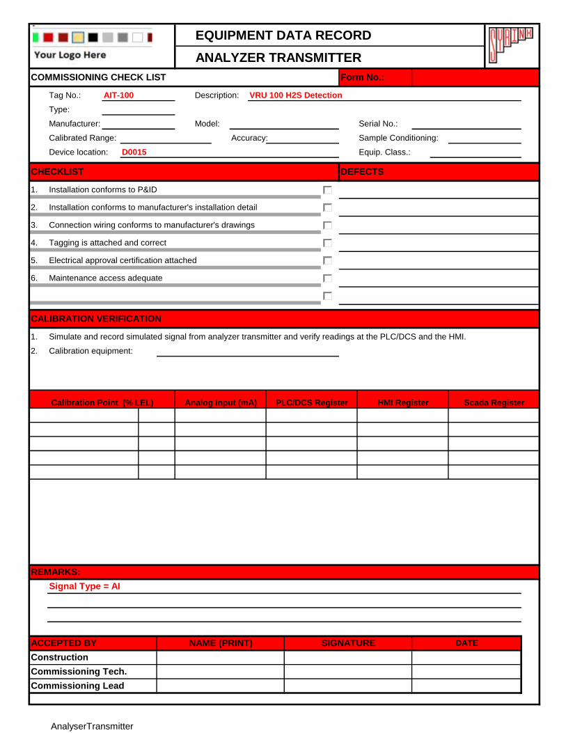
EQUIPMENT DATA RECORD
ANALYZER TRANSMITTER
Tag No.: AIT-100 Description: VRU 100 H2S Detection
Type:
Manufacturer: Model: Serial No.:
Calibrated Range: Accuracy: Sample Conditioning:
Device location: D0015 Equip. Class.:
1.
2.
3.
4.
5.
6.
1.
2. Calibration equipment:
Construction
Commissioning Tech.
Signal Type = AI
REMARKS:
Simulate and record simulated signal from analyzer transmitter and verify readings at the PLC/DCS and the HMI.
Scada RegisterHMI RegisterAnalog Input (mA)
Commissioning Lead
ACCEPTED BY NAME (PRINT) SIGNATURE DATE
Installation conforms to P&ID
Installation conforms to manufacturer's installation detail
DEFECTSCHECKLIST
COMMISSIONING CHECK LIST
Tagging is attached and correct
Form No.:
Connection wiring conforms to manufacturer's drawings
CALIBRATION VERIFICATION
Electrical approval certification attached
PLC/DCS Register
Maintenance access adequate
Calibration Point (% LEL)
AnalyserTransmitter
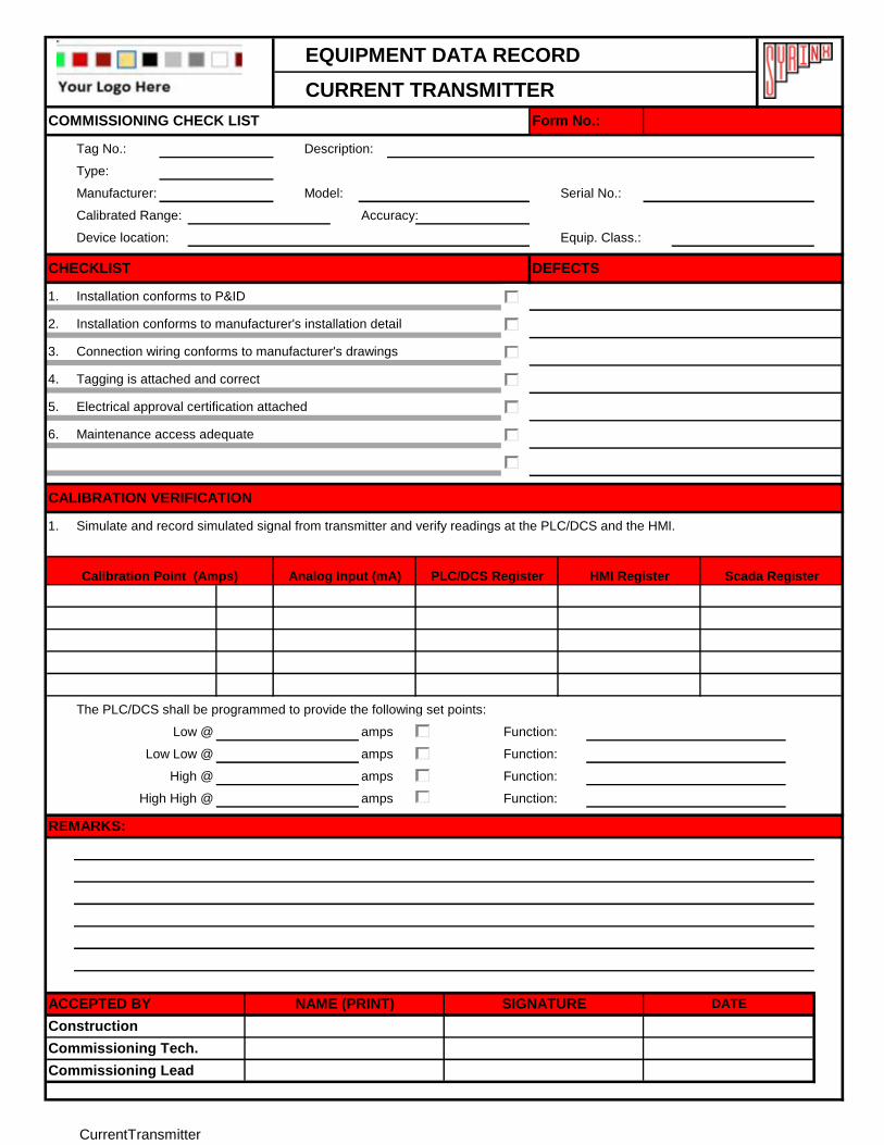
EQUIPMENT DATA RECORD
CURRENT TRANSMITTER
Tag No.: Description:
Type:
Manufacturer: Model: Serial No.:
Calibrated Range: Accuracy:
Device location: Equip. Class.:
1.
2.
3.
4.
5.
6.
1.
The PLC/DCS shall be programmed to provide the following set points:
amps Function:
amps Function:
amps Function:
amps Function:
CALIBRATION VERIFICATION
Tagging is attached and correct
Electrical approval certification attached
Maintenance access adequate
Installation conforms to P&ID
Installation conforms to manufacturer's installation detail
DEFECTSCHECKLIST
COMMISSIONING CHECK LIST Form No.:
Connection wiring conforms to manufacturer's drawings
Commissioning Lead
Commissioning Tech.
Construction
ACCEPTED BY NAME (PRINT) SIGNATURE DATE
REMARKS:
Simulate and record simulated signal from transmitter and verify readings at the PLC/DCS and the HMI.
Scada RegisterHMI Register
High High @
Low @
Low Low @
High @
Calibration Point (Amps) Analog Input (mA) PLC/DCS Register
CurrentTransmitter
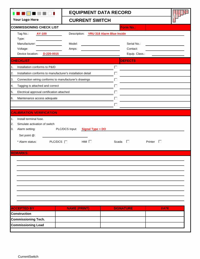
EQUIPMENT DATA RECORD
CURRENT SWITCH
Tag No.: AY-100 Description: VRU 318 Alarm Blue Inside
Type:
Manufacturer: Model: Serial No.:
Voltage: Amps: Contact:
Device location: D-220-0015 Equip. Class.:
1.
2.
3.
4.
5.
6.
1.
2.
3. Alarm setting: PLC/DCS Input: Signal Type = DO
Set point @:
* Alarm status: PLC/DCS HMI Scada Printer
Install terminal fuse.
Simulate activation of switch
Commissioning Tech.
Commissioning Lead
ACCEPTED BY NAME (PRINT) SIGNATURE DATE
Construction
CALIBRATION VERIFICATION
COMMISSIONING CHECK LIST
Maintenance access adequate
Installation conforms to manufacturer's installation detail
Connection wiring conforms to manufacturer's drawings
Form No.:
Installation conforms to P&ID
DEFECTSCHECKLIST
Tagging is attached and correct
Electrical approval certification attached
REMARKS:
CurrentSwitch
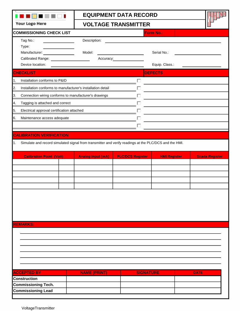
EQUIPMENT DATA RECORD
VOLTAGE TRANSMITTER
Tag No.: Description:
Type:
Manufacturer: Model: Serial No.:
Calibrated Range: Accuracy:
Device location: Equip. Class.:
1.
2.
3.
4.
5.
6.
1.
HMI RegisterCalibration Point (Volt) Analog Input (mA) PLC/DCS Register
Commissioning Lead
REMARKS:
Simulate and record simulated signal from transmitter and verify readings at the PLC/DCS and the HMI.
Scada Register
ACCEPTED BY NAME (PRINT) SIGNATURE DATE
Construction
Commissioning Tech.
COMMISSIONING CHECK LIST Form No.:
Connection wiring conforms to manufacturer's drawings
Installation conforms to P&ID
Installation conforms to manufacturer's installation detail
DEFECTSCHECKLIST
Tagging is attached and correct
Electrical approval certification attached
Maintenance access adequate
CALIBRATION VERIFICATION
VoltageTransmitter
EQUIPMENT DATA RECORD
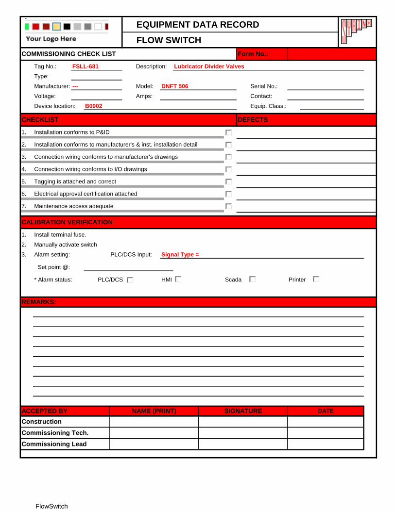
FLOW SWITCH
Tag No.: FSLL-681 Description: Lubricator Divider Valves
Type:
Manufacturer: --- Model: DNFT 506 Serial No.:
Voltage: Amps: Contact:
Device location: B0902 Equip. Class.:
1.
2.
3.
4.
5.
6.
7.
1.
2.
3. Alarm setting: PLC/DCS Input: Signal Type =
Set point @:
* Alarm status: PLC/DCS HMI Scada Printer
REMARKS:
CALIBRATION VERIFICATION
Tagging is attached and correct
Maintenance access adequate
Electrical approval certification attached
Installation conforms to manufacturer's & inst. installation detail
Connection wiring conforms to manufacturer's drawings
DEFECTSCHECKLIST
Connection wiring conforms to I/O drawings
Commissioning Lead
NAME (PRINT)
Construction
Commissioning Tech.
COMMISSIONING CHECK LIST Form No.:
Installation conforms to P&ID
Install terminal fuse.
Manually activate switch
ACCEPTED BY SIGNATURE DATE
FlowSwitch
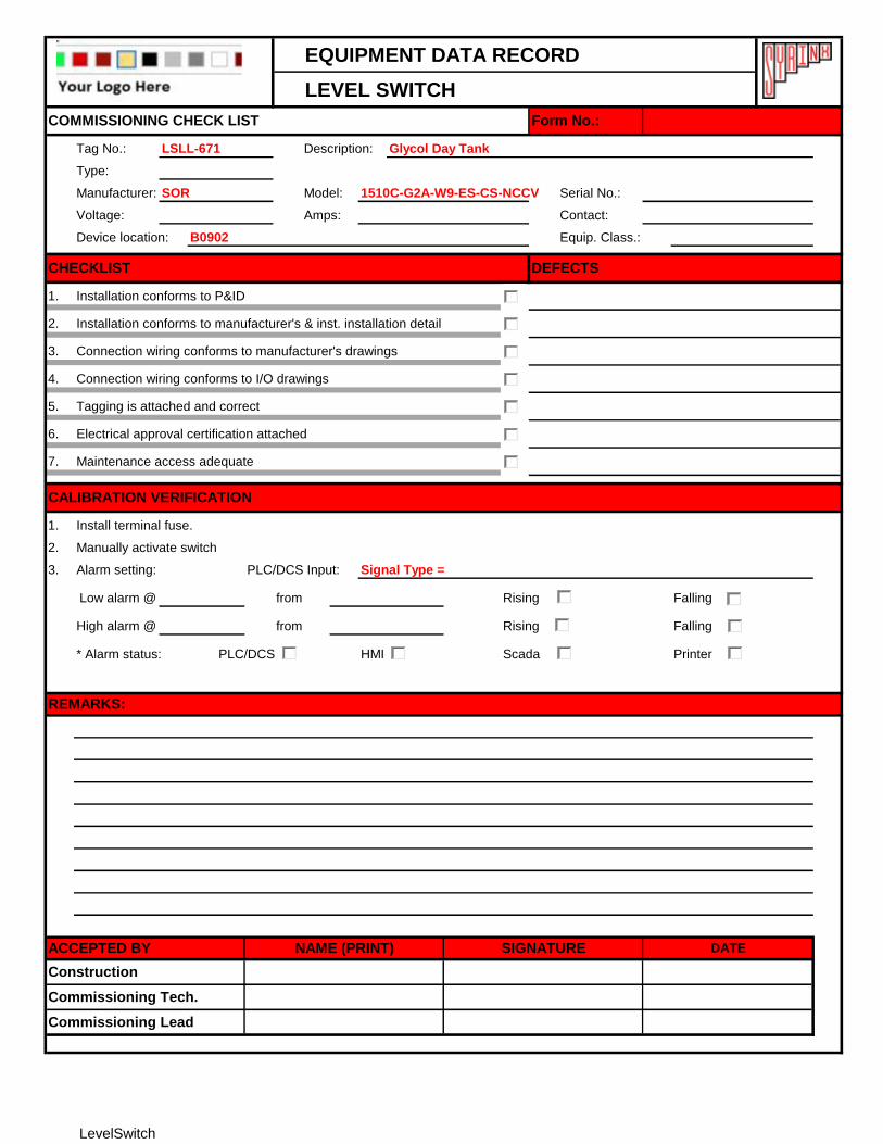
EQUIPMENT DATA RECORD
LEVEL SWITCH
Tag No.: LSLL-671 Description: Glycol Day Tank
Type:
Manufacturer: SOR Model: 1510C-G2A-W9-ES-CS-NCCV Serial No.:
Voltage: Amps: Contact:
Device location: B0902 Equip. Class.:
1.
2.
3.
4.
5.
6.
7.
1.
2.
3. Alarm setting: PLC/DCS Input: Signal Type =
Low alarm @ from Rising Falling
High alarm @ from Rising Falling
* Alarm status: PLC/DCS HMI Scada Printer
Installation conforms to manufacturer's & inst. installation detail
Connection wiring conforms to manufacturer's drawings
CHECKLIST
Tagging is attached and correct
Electrical approval certification attached
Maintenance access adequate
Install terminal fuse.
Manually activate switch
Connection wiring conforms to I/O drawings
CALIBRATION VERIFICATION
COMMISSIONING CHECK LIST Form No.:
Installation conforms to P&ID
DEFECTS
REMARKS:
ACCEPTED BY NAME (PRINT) SIGNATURE DATE
Construction
Commissioning Lead
Commissioning Tech.
LevelSwitch
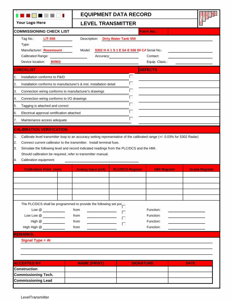
EQUIPMENT DATA RECORD
LEVEL TRANSMITTER
Tag No.: LIT-550 Description: Dirty Water Tank 550
Type:
Manufacturer: Rosemount Model: 5302 H A 1 S 1 E 5A E 036 00 CA E6 M1Serial No.:
Calibrated Range: Accuracy: Contact:
Device location: B0902 Equip. Class.:
1.
2.
3.
4.
5.
6.
7.
1.
2.
3.
Should calibration be required, refer to transmitter manual.
4. Calibration equipment:
The PLC/DCS shall be programmed to provide the following set points:
Low @ from Function:
Low Low @ from Function:
High @ from Function:
High High @ from Function:
Signal Type = AI
HMI RegisterCalibration Point (mm) Analog Input (mA)
Calibrate level transmitter loop to an accuracy setting representative of the calibrated range (+/- 0.03% for 5302 Radar)
Simulate the following level and record indicated readings from the PLC/DCS and the HMI.
Scada Register
Connection wiring conforms to I/O drawings
Tagging is attached and correct
Electrical approval certification attached
Connect current calibrator to the transmitter. Install terminal fuse.
CALIBRATION VERIFICATION
Maintenance access adequate
ACCEPTED BY NAME (PRINT)
Installation conforms to P&ID
Installation conforms to manufacturer's & inst. installation detail
Connection wiring conforms to manufacturer's drawings
DEFECTSCHECKLIST
COMMISSIONING CHECK LIST Form No.:
Construction
SIGNATURE DATE
REMARKS:
Commissioning Lead
Commissioning Tech.
PLC/DCS Register
LevelTransmitter
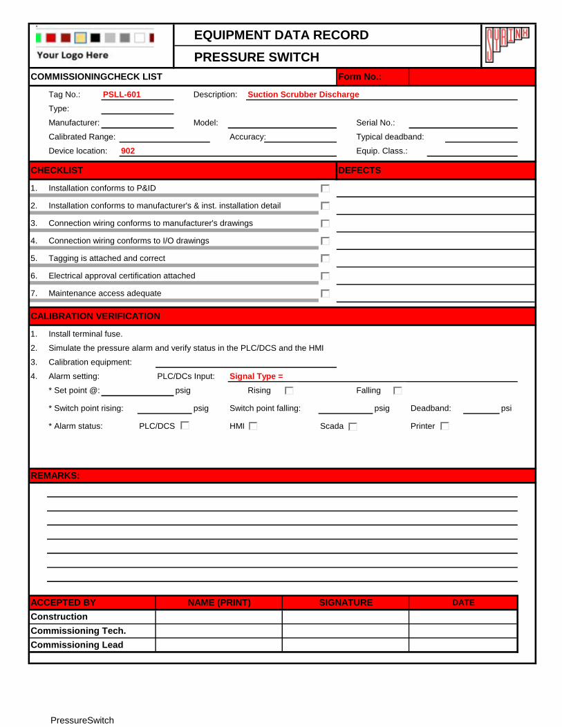
EQUIPMENT DATA RECORD
PRESSURE SWITCH
Tag No.: PSLL-601 Description: Suction Scrubber Discharge
Type:
Manufacturer: Model: Serial No.:
Calibrated Range: Accuracy: Typical deadband:
Device location: 902 Equip. Class.:
1.
2.
3.
4.
5.
6.
7.
1.
2.
3. Calibration equipment:
4. Alarm setting: PLC/DCs Input: Signal Type =
* Set point @: psig Rising Falling
* Switch point rising: psig Switch point falling: psig Deadband: psi
* Alarm status: PLC/DCS HMI Scada Printer
Commissioning Lead
Commissioning Tech.
Construction
ACCEPTED BY NAME (PRINT) SIGNATURE DATE
COMMISSIONINGCHECK LIST Form No.:
Installation conforms to P&ID
Installation conforms to manufacturer's & inst. installation detail
Connection wiring conforms to manufacturer's drawings
DEFECTSCHECKLIST
Connection wiring conforms to I/O drawings
Tagging is attached and correct
Electrical approval certification attached
Maintenance access adequate
Install terminal fuse.
Simulate the pressure alarm and verify status in the PLC/DCS and the HMI
CALIBRATION VERIFICATION
REMARKS:
PressureSwitch
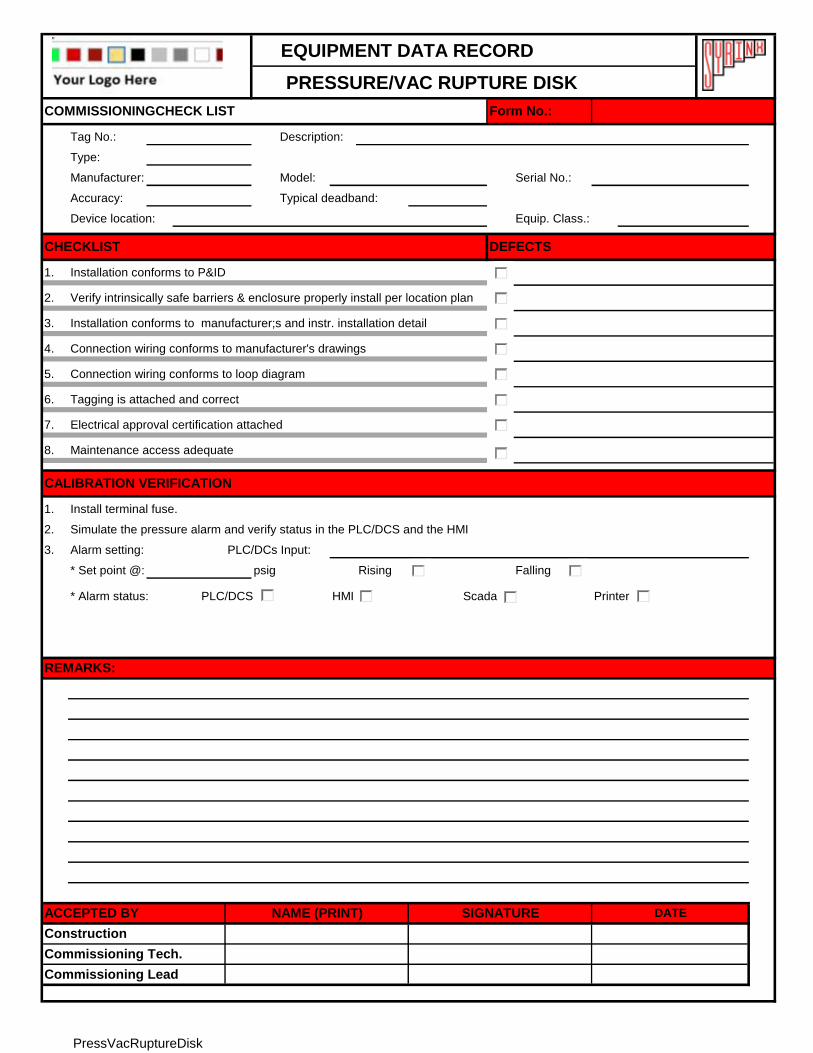
EQUIPMENT DATA RECORD
PRESSURE/VAC RUPTURE DISK
Tag No.: Description:
Type:
Manufacturer: Model: Serial No.:
Accuracy: Typical deadband:
Device location: Equip. Class.:
1.
2.
3.
4.
5.
6.
7.
8.
1.
2.
3. Alarm setting: PLC/DCs Input:
* Set point @: psig Rising Falling
* Alarm status: PLC/DCS HMI Scada Printer
DEFECTSCHECKLIST
Connection wiring conforms to manufacturer's drawings
Installation conforms to P&ID
Commissioning Lead
Construction
COMMISSIONINGCHECK LIST Form No.:
Verify intrinsically safe barriers & enclosure properly install per location plan
Commissioning Tech.
ACCEPTED BY DATE
REMARKS:
Tagging is attached and correct
Electrical approval certification attached
NAME (PRINT) SIGNATURE
Maintenance access adequate
Installation conforms to manufacturer;s and instr. installation detail
Connection wiring conforms to loop diagram
Install terminal fuse.
Simulate the pressure alarm and verify status in the PLC/DCS and the HMI
CALIBRATION VERIFICATION
PressVacRuptureDisk
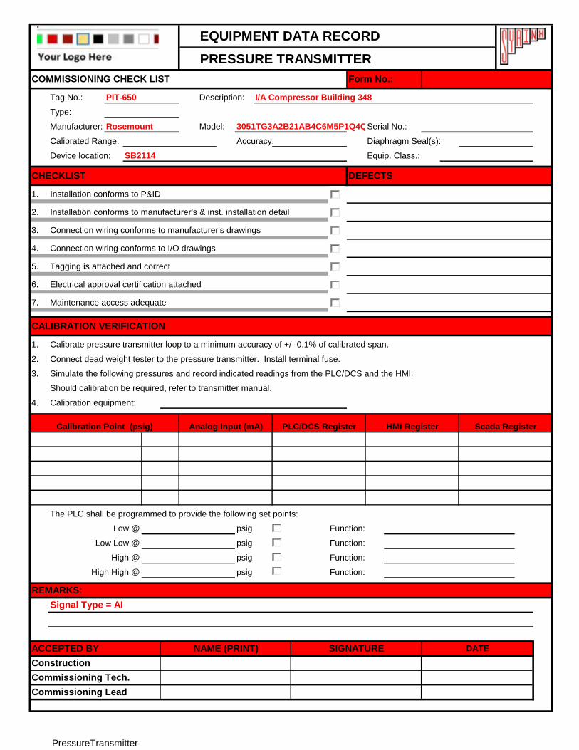
EQUIPMENT DATA RECORD
PRESSURE TRANSMITTER
Tag No.: PIT-650 Description: I/A Compressor Building 348
Type:
Manufacturer: Rosemount Model: 3051TG3A2B21AB4C6M5P1Q4Q8Serial No.:
Calibrated Range: Accuracy: Diaphragm Seal(s):
Device location: SB2114 Equip. Class.:
1.
2.
3.
4.
5.
6.
7.
1.
2.
3.
Should calibration be required, refer to transmitter manual.
4. Calibration equipment:
The PLC shall be programmed to provide the following set points:
psig Function:
psig Function:
psig Function:
psig Function:
REMARKS:
Low Low @
High @
High High @
Commissioning Tech.
Commissioning Lead
ACCEPTED BY NAME (PRINT) SIGNATURE DATE
Construction
COMMISSIONING CHECK LIST Form No.:
Installation conforms to P&ID
Calibration Point (psig)
Installation conforms to manufacturer's & inst. installation detail
Connection wiring conforms to manufacturer's drawings
DEFECTSCHECKLIST
Simulate the following pressures and record indicated readings from the PLC/DCS and the HMI.
Low @
Maintenance access adequate
Connect dead weight tester to the pressure transmitter. Install terminal fuse.
HMI Register Scada Register
CALIBRATION VERIFICATION
Connection wiring conforms to I/O drawings
Tagging is attached and correct
Calibrate pressure transmitter loop to a minimum accuracy of +/- 0.1% of calibrated span.
Electrical approval certification attached
Analog Input (mA) PLC/DCS Register
Signal Type = AI
PressureTransmitter
EQUIPMENT DATA RECORD
TEMPERATURE DEVICE -THERMOCOUPLE
Tag No.: TE -6060A Description: Melter Temperature
Type:
Manufacturer: Model: Serial No.:
Calibrated Range: Accuracy:
Device location: 107-019 Equip. Class.:
1.
2.
3.
4.
5.
6.
7.
1.
2.
Setpoint: In Protection Relay In PLC/DCS
PLC/DCS Input: I/O Type = TC ; Card ID = TC06_G6_1112 : Channel = 0
°C Function:
°C Function:
* Alarm status: PLC/DCS HMI Scada Printer
Commissioning Lead
Commissioning Tech.
Construction
ACCEPTED BY NAME (PRINT) SIGNATURE DATE
COMMISSIONING CHECK LIST Form No.:
DEFECTSCHECKLIST
Installation conforms to P&ID
Installation conforms to manufacturer's installation detail
Connection wiring conforms to I/O drawings
Tagging is attached and correct
Electrical approval certification attached
(and/or Motor Protection Relay) according to calibration Table.
Simulate the following temperature and record indicated readings from the PLC/DCS and the HMI
CALIBRATION VERIFICATION
Connect precision Millivolt Source to the loop.
Scada Register
REMARKS:
Alarm @:
Trip @:
Maintenance access adequate
Connection wiring conforms to manufacturer's drawings
HMI RegisterCalibration Point (mV) Equivalent Temp (°C) PLC/DCS Register
Thermocouple

EQUIPMENT DATA RECORD
RESISTIVE TEMPERATURE DEVICE - RTD
Tag No.: Description:
Type:
Manufacturer: Model: Serial No.:
Calibrated Range: Accuracy:
Device location: Equip. Class.:
1.
2.
3.
4.
5.
6.
7.
1.
2.
Setpoint: In Protection Relay In PLC/DCS
PLC/DCS Input:
°C Function:
°C Function:
* Alarm status: PLC/DCS HMI Scada Printer
Connection wiring conforms to I/O drawings
Tagging is attached and correct
Electrical approval certification attached
Maintenance access adequate
(and/or Motor Protection Relay).
Calibration Point (Ohm)
CALIBRATION VERIFICATION
Simulate the following temperature and record indicated readings from the PLC/DCS and the HMI
Connect precision decade box at RTD (or at junction box at end of the loop).
ACCEPTED BY NAME (PRINT) SIGNATURE DATE
HMI Register
DEFECTSCHECKLIST
COMMISSIONING CHECK LIST Form No.:
Installation conforms to P&ID
Installation conforms to manufacturer's installation detail
Connection wiring conforms to manufacturer's drawings
Construction
Commissioning Tech.
Commissioning Lead
REMARKS:
Alarm @:
Trip @:
Scada RegisterEquivalent Temp (°C) PLC/DCS Register
RTD
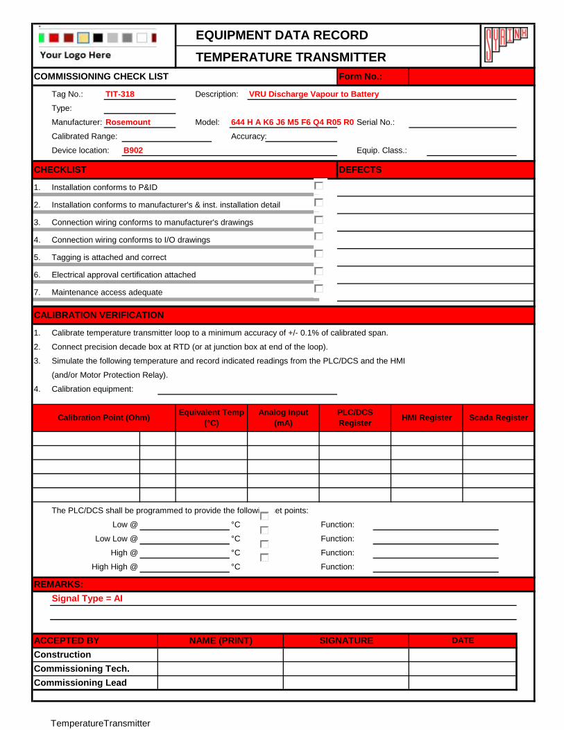
EQUIPMENT DATA RECORD
TEMPERATURE TRANSMITTER
Tag No.: TIT-318 Description: VRU Discharge Vapour to Battery
Type:
Manufacturer: Rosemount Model: 644 H A K6 J6 M5 F6 Q4 R05 R07 R12 R21 R25Serial No.:
Calibrated Range: Accuracy:
Device location: B902 Equip. Class.:
1.
2.
3.
4.
5.
6.
7.
1.
2.
3.
4. Calibration equipment:
The PLC/DCS shall be programmed to provide the following set points:
°C Function:
°C Function:
°C Function:
°C Function:
Calibrate temperature transmitter loop to a minimum accuracy of +/- 0.1% of calibrated span.
Signal Type = AI
CALIBRATION VERIFICATION
Simulate the following temperature and record indicated readings from the PLC/DCS and the HMI
(and/or Motor Protection Relay).
Scada Register
Connection wiring conforms to I/O drawings
Tagging is attached and correct
Electrical approval certification attached
Low @
Maintenance access adequate
Connect precision decade box at RTD (or at junction box at end of the loop).
ACCEPTED BY NAME (PRINT)
Installation conforms to P&ID
Installation conforms to manufacturer's & inst. installation detail
Connection wiring conforms to manufacturer's drawings
High @
High High @
DEFECTSCHECKLIST
SIGNATURE DATE
Construction
COMMISSIONING CHECK LIST Form No.:
Commissioning Lead
Commissioning Tech.
REMARKS:
Low Low @
Calibration Point (Ohm) HMI RegisterPLC/DCS
Register
Analog Input
(mA)
Equivalent Temp
(°C)
TemperatureTransmitter
EQUIPMENT DATA RECORD
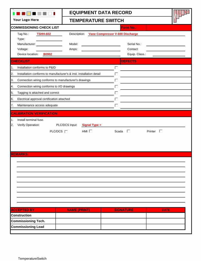
TEMPERATURE SWITCH
Tag No.: TSHH-602 Description: Vane Compressor V-600 Discharge
Type:
Manufacturer: Model: Serial No.:
Voltage: Amps: Contact:
Device location: B0902 Equip. Class.:
1.
2.
3.
4.
5.
6.
7.
1.
2. Verify Operation: PLC/DCS Input: Signal Type =
PLC/DCS HMI Scada Printer
Install terminal fuse.
Commissioning Tech.
Commissioning Lead
ACCEPTED BY NAME (PRINT) SIGNATURE DATE
Construction
CALIBRATION VERIFICATION
COMMISSIONING CHECK LIST
Electrical approval certification attached
Installation conforms to manufacturer's & inst. installation detail
Connection wiring conforms to manufacturer's drawings
Form No.:
Installation conforms to P&ID
DEFECTSCHECKLIST
Connection wiring conforms to I/O drawings
Tagging is attached and correct
Maintenance access adequate
REMARKS:
TemperatureSwitch
EQUIPMENT DATA RECORD
TEMPERATURE CONTROLLER OUTPUT
Tag No.: Description:
Type:
Manufacturer: Model: Serial No.:
Calibrated Range: Accuracy: Contact:
Device location: Equip. Class.:
1.
2.
3.
4.
5.
6.
1.
2.
3.
Should calibration be required, refer to Control Valve manual.
The PLC/DCS shall be checked for following
Air Failure Opens Closes Last Position
Signal Failure Opens Closes Last Position
Control to Valve PLC/DCS Output:
Commissioning Tech.
Commissioning Lead
ACCEPTED BY NAME (PRINT) SIGNATURE DATE
Construction
COMMISSIONING CHECK LIST Form No.:
Installation conforms to P&ID
DEFECTSCHECKLIST
Connect Control Valve. Install terminal fuse.
CALIBRATION VERIFICATION
Installation conforms to manufacturer's installation detail
Connection wiring conforms to manufacturer's drawings
Tagging is attached and correct
Electrical approval certification attached
Maintenance access adequate
Simulate Valve action and record indicated readings from the PLC/DCS and the HMI.
HMI Register
Calibrate Control Valve as per Datasheet.
Valve Position Analog Output (mA) PLC/DCS Register Scada Register
REMARKS:
Open/Close
75% / 25%
50%
25% / 75%
Close/Open
TempControllerOutput
EQUIPMENT DATA RECORD
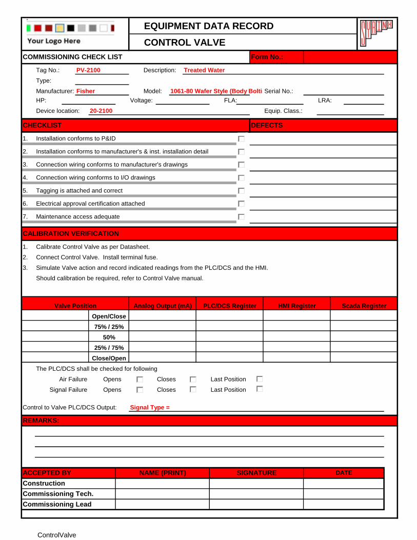
CONTROL VALVE
Tag No.: PV-2100 Description: Treated Water
Type:
Manufacturer: Fisher Model: 1061-80 Wafer Style (Body Bolting) V250Serial No.:
HP: Voltage: FLA: LRA:
Device location: 20-2100 Equip. Class.:
1.
2.
3.
4.
5.
6.
7.
1.
2.
3.
Should calibration be required, refer to Control Valve manual.
The PLC/DCS shall be checked for following
Air Failure Opens Closes Last Position
Signal Failure Opens Closes Last Position
Control to Valve PLC/DCS Output: Signal Type =
REMARKS:
Commissioning Lead
Commissioning Tech.
Construction
ACCEPTED BY NAME (PRINT) SIGNATURE DATE
COMMISSIONING CHECK LIST Form No.:
Installation conforms to P&ID
Installation conforms to manufacturer's & inst. installation detail
Connection wiring conforms to manufacturer's drawings
DEFECTSCHECKLIST
Tagging is attached and correct
Electrical approval certification attached
Connect Control Valve. Install terminal fuse.
CALIBRATION VERIFICATION
Maintenance access adequate
Calibrate Control Valve as per Datasheet.
Simulate Valve action and record indicated readings from the PLC/DCS and the HMI.
Scada Register
Connection wiring conforms to I/O drawings
HMI RegisterValve Position Analog Output (mA) PLC/DCS Register
Open/Close
75% / 25%
50%
25% / 75%
Close/Open
ControlValve
EQUIPMENT DATA RECORD
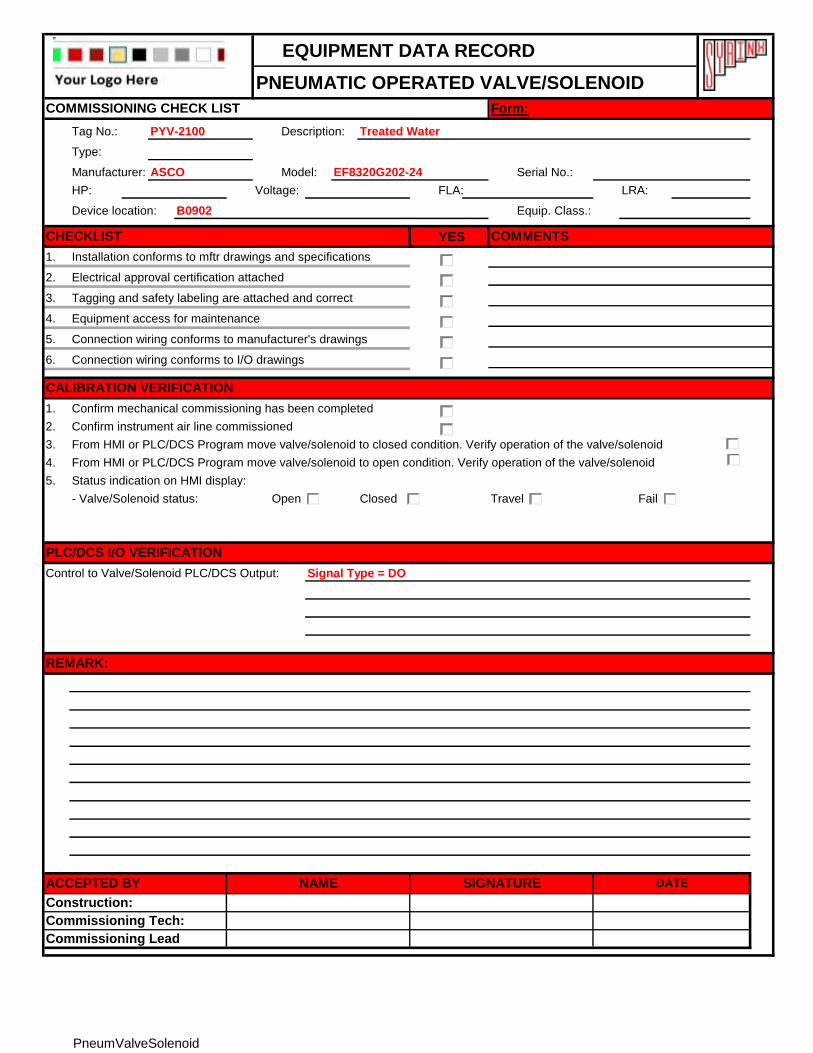
PNEUMATIC OPERATED VALVE/SOLENOID
Tag No.: PYV-2100 Description: Treated Water
Type:
Manufacturer: ASCO Model: EF8320G202-24 Serial No.:
HP: Voltage: FLA: LRA:
Device location: B0902 Equip. Class.:
YES
1. Installation conforms to mftr drawings and specifications
2. Electrical approval certification attached
3. Tagging and safety labeling are attached and correct
4. Equipment access for maintenance
5.
6.
1. Confirm mechanical commissioning has been completed
2. Confirm instrument air line commissioned
3. From HMI or PLC/DCS Program move valve/solenoid to closed condition. Verify operation of the valve/solenoid
4. From HMI or PLC/DCS Program move valve/solenoid to open condition. Verify operation of the valve/solenoid
5. Status indication on HMI display:
Open Closed Travel Fail
Control to Valve/Solenoid PLC/DCS Output: Signal Type = DO
Form:
CALIBRATION VERIFICATION
Commissioning Tech:
Commissioning Lead
Connection wiring conforms to manufacturer's drawings
Connection wiring conforms to I/O drawings
Construction:
CHECKLIST COMMENTS
- Valve/Solenoid status:
COMMISSIONING CHECK LIST
PLC/DCS I/O VERIFICATION
REMARK:
SIGNATURENAMEACCEPTED BY DATE
PneumValveSolenoid
EQUIPMENT DATA RECORD
SCR ANALOG CONTROL
Tag No.: Description:
Type:
Manufacturer: Model: Serial No.:
Calibrated Range: Accuracy: Contact:
Device location: Equip. Class.:
1.
2.
3.
4.
5.
6.
7.
1.
2.
3. Verify analog output operation as per vendor manual.
Install terminal fuse.
Connection wiring conforms to I/O drawings
Tagging is attached and correct
Electrical approval certification attached
From HMI or PLC/DCS program simulate signals to SCR Controller.
CALIBRATION VERIFICATION
Maintenance access adequate
ACCEPTED BY NAME (PRINT)
Installation conforms to P&ID
Installation conforms to manufacturer's installation detail
Connection wiring conforms to manufacturer's drawings
DEFECTSCHECKLIST
COMMISSIONING CHECK LIST Form No.:
Construction
SIGNATURE DATE
REMARKS:
Commissioning Lead
Commissioning Tech.
SCRAnalogControl
EQUIPMENT DATA RECORD
SCR DIGITAL CONTROL
Tag No.: Description:
Type:
Manufacturer: Model: Serial No.:
Calibrated Range: Accuracy: Contact:
Device location: Equip. Class.:
1.
2.
3.
4.
5.
6.
7.
1.
2.
3.
REMARKS:
Commissioning Lead
Commissioning Tech.
Construction
ACCEPTED BY NAME (PRINT) SIGNATURE DATE
COMMISSIONING CHECK LIST Form No.:
Installation conforms to P&ID
Installation conforms to manufacturer's installation detail
Connection wiring conforms to manufacturer's drawings
DEFECTSCHECKLIST
Connection wiring conforms to I/O drawings
Tagging is attached and correct
Electrical approval certification attached
From HMI or PLC/DCS program simulate signals to SCR Controller.
CALIBRATION VERIFICATION
Maintenance access adequate
Verify digital output operation as per vendor manual.
Install terminal fuse.
SCRDigitalControl
EQUIPMENT DATA RECORD
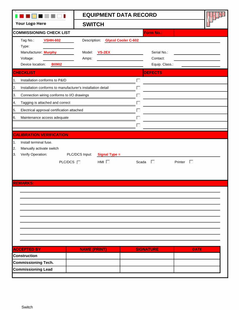
SWITCH
Tag No.: VSHH-602 Description: Glycol Cooler C-602
Type:
Manufacturer: Murphy Model: VS-2EX Serial No.:
Voltage: Amps: Contact:
Device location: B0902 Equip. Class.:
1.
2.
3.
4.
5.
6.
1.
2.
3. Verify Operation: PLC/DCS Input: Signal Type =
PLC/DCS HMI Scada Printer
REMARKS:
Maintenance access adequate
Installation conforms to manufacturer's installation detail
Connection wiring conforms to I/O drawings
CALIBRATION VERIFICATION
Electrical approval certification attached
COMMISSIONING CHECK LIST Form No.:
Installation conforms to P&ID
DEFECTSCHECKLIST
ACCEPTED BY NAME (PRINT) SIGNATURE DATE
Construction
Tagging is attached and correct
Commissioning Lead
Commissioning Tech.
Install terminal fuse.
Manually activate switch
Switch
EQUIPMENT DATA RECORD
SWITCH (JOG-OFF-AUTO)
Tag No.: HS-140 Description: Skim Pump P-140
Type:
Manufacturer: By Vendor Model: By Vendor Serial No.:
Voltage: Amps: Contact:
Device location: 220-2111 Equip. Class.:
1.
2.
3.
4.
5.
6.
1.
2.
3. Verify Operation: PLC/DCS Input AUTO Position: Signal Type = DI
PLC/DCS Input JOG Position:
PLC/DCS Input OFF Position:
PLC/DCS HMI Scada Printer
COMMISSIONING CHECK LIST Form No.:
CHECKLIST DEFECTS
Installation conforms to P&ID
Installation conforms to manufacturer's installation detail
Connection wiring conforms to I/O drawings
Tagging is attached and correct
Electrical approval certification attached
Maintenance access adequate
CALIBRATION VERIFICATION
Install terminal fuse.
Manually activate switch
REMARKS:
ACCEPTED BY NAME (PRINT) SIGNATURE DATE
Commissioning Lead
Construction
Commissioning Tech.
SwitchJOA
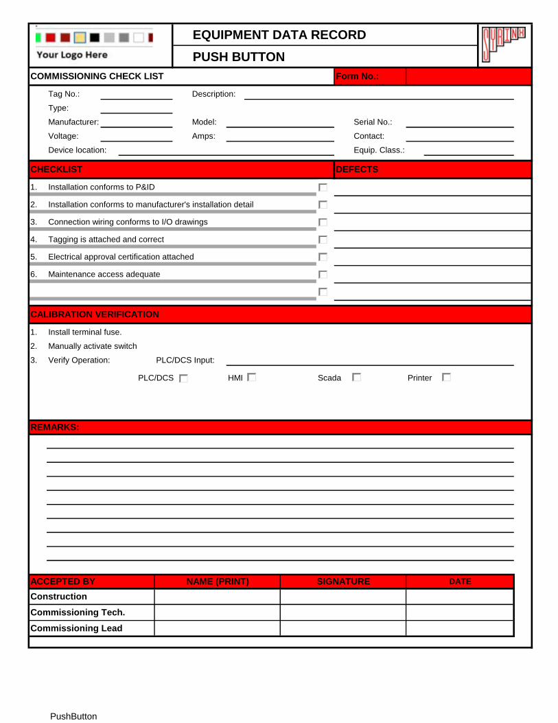
EQUIPMENT DATA RECORD
PUSH BUTTON
Tag No.: Description:
Type:
Manufacturer: Model: Serial No.:
Voltage: Amps: Contact:
Device location: Equip. Class.:
1.
2.
3.
4.
5.
6.
1.
2.
3. Verify Operation: PLC/DCS Input:
PLC/DCS HMI Scada Printer
Install terminal fuse.
Manually activate switch
Commissioning Tech.
Commissioning Lead
ACCEPTED BY NAME (PRINT) SIGNATURE DATE
Construction
CALIBRATION VERIFICATION
COMMISSIONING CHECK LIST
Maintenance access adequate
Installation conforms to manufacturer's installation detail
Connection wiring conforms to I/O drawings
Form No.:
Installation conforms to P&ID
DEFECTSCHECKLIST
Tagging is attached and correct
Electrical approval certification attached
REMARKS:
PushButton
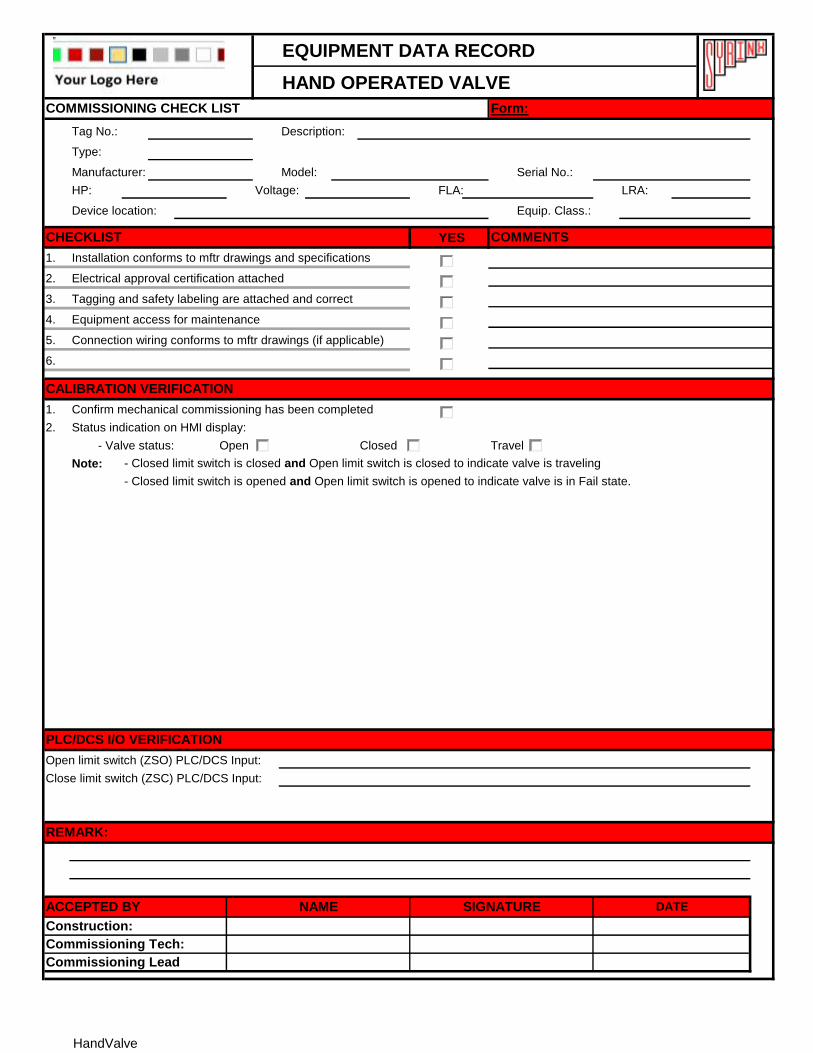
EQUIPMENT DATA RECORD
HAND OPERATED VALVE
Tag No.: Description:
Type:
Manufacturer: Model: Serial No.:
HP: Voltage: FLA: LRA:
Device location: Equip. Class.:
YES
1. Installation conforms to mftr drawings and specifications
2. Electrical approval certification attached
3. Tagging and safety labeling are attached and correct
4. Equipment access for maintenance
5.
6.
1. Confirm mechanical commissioning has been completed
2. Status indication on HMI display:
- Valve status: Open Closed Travel
Note: - Closed limit switch is closed and Open limit switch is closed to indicate valve is traveling
- Closed limit switch is opened and Open limit switch is opened to indicate valve is in Fail state.
Open limit switch (ZSO) PLC/DCS Input:
Close limit switch (ZSC) PLC/DCS Input:
PLC/DCS I/O VERIFICATION
REMARK:
SIGNATURENAMEACCEPTED BY DATE
Commissioning Tech:
Connection wiring conforms to mftr drawings (if applicable)
CALIBRATION VERIFICATION
COMMENTS
Commissioning Lead
Construction:
Form:COMMISSIONING CHECK LIST
CHECKLIST
HandValve
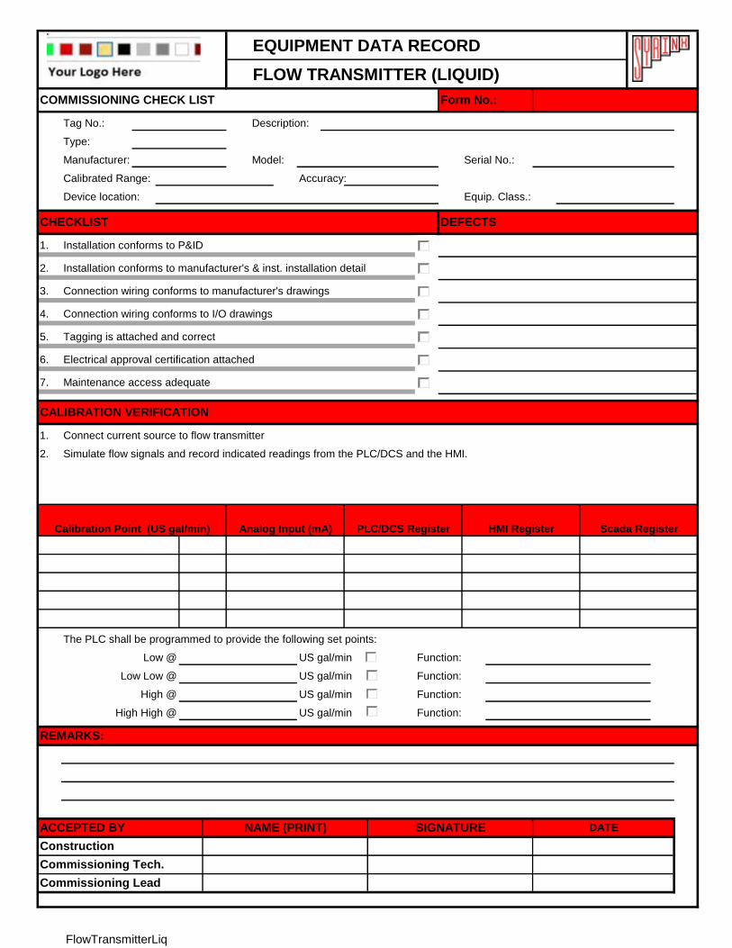
EQUIPMENT DATA RECORD
FLOW TRANSMITTER (LIQUID)
Tag No.: Description:
Type:
Manufacturer: Model: Serial No.:
Calibrated Range: Accuracy:
Device location: Equip. Class.:
1.
2.
3.
4.
5.
6.
7.
1.
2.
The PLC shall be programmed to provide the following set points:
US gal/min Function:
US gal/min Function:
US gal/min Function:
US gal/min Function:
Low @
CALIBRATION VERIFICATION
Connection wiring conforms to I/O drawings
Tagging is attached and correct
Electrical approval certification attached
Maintenance access adequate
HMI Register Scada RegisterAnalog Input (mA) PLC/DCS Register
Connect current source to flow transmitter
Connection wiring conforms to manufacturer's drawings
Simulate flow signals and record indicated readings from the PLC/DCS and the HMI.
Calibration Point (US gal/min)
DEFECTSCHECKLIST
Installation conforms to P&ID
Installation conforms to manufacturer's & inst. installation detail
COMMISSIONING CHECK LIST Form No.:
ACCEPTED BY NAME (PRINT)
Construction
Commissioning Lead
Commissioning Tech.
SIGNATURE DATE
REMARKS:
Low Low @
High @
High High @
FlowTransmitterLiq
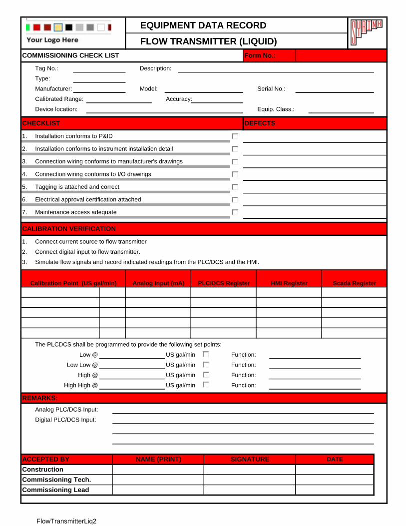
EQUIPMENT DATA RECORD
FLOW TRANSMITTER (LIQUID)
Tag No.: Description:
Type:
Manufacturer: Model: Serial No.:
Calibrated Range: Accuracy:
Device location: Equip. Class.:
1.
2.
3.
4.
5.
6.
7.
1.
2.
3.
The PLCDCS shall be programmed to provide the following set points:
US gal/min Function:
US gal/min Function:
US gal/min Function:
US gal/min Function:
Simulate flow signals and record indicated readings from the PLC/DCS and the HMI.
Digital PLC/DCS Input:
Analog PLC/DCS Input:
REMARKS:
Low Low @
High @
High High @
Commissioning Tech.
Commissioning Lead
ACCEPTED BY NAME (PRINT) SIGNATURE DATE
Construction
COMMISSIONING CHECK LIST Form No.:
Installation conforms to P&ID
DEFECTSCHECKLIST
Low @
Maintenance access adequate
Installation conforms to instrument installation detail
Connection wiring conforms to manufacturer's drawings
CALIBRATION VERIFICATION
Connection wiring conforms to I/O drawings
Tagging is attached and correct
Calibration Point (US gal/min)
Connect digital input to flow transmitter.
HMI Register Scada Register
Connect current source to flow transmitter
Electrical approval certification attached
Analog Input (mA) PLC/DCS Register
FlowTransmitterLiq2
EQUIPMENT DATA RECORD
FLOW TRANSMITTER (GAS)
Tag No.: Description:
Type:
Manufacturer: Model: Serial No.:
Calibrated Range: Accuracy:
Device location: Equip. Class.:
1.
2.
3.
4.
5.
6.
7.
1.
2.
The PLC shall be programmed to provide the following set points:
SCFN Function:
SCFN Function:
SCFN Function:
SCFN Function:
Commissioning Tech.
ACCEPTED BY NAME (PRINT) SIGNATURE
Commissioning Lead
DATE
Construction
COMMISSIONING CHECK LIST Form No.:
Connection wiring conforms to I/O drawings
Tagging is attached and correct
Electrical approval certification attached
Installation conforms to P&ID
Installation conforms to manufacturer's & inst. installation detail
Connection wiring conforms to manufacturer's drawings
DEFECTSCHECKLIST
Low @
Maintenance access adequate
Low Low @
High @
Simulate flow signals and record indicated readings from the PLC/DCS and the HMI.
HMI RegisterCalibration Point (scfh) Analog Input (mA) PLC/DCS Register
Connect current source to flow transmitter
CALIBRATION VERIFICATION
REMARKS:
High High @
Scada Register
FlowTransmitterGas
EQUIPMENT DATA RECORD
MOTOR OPERATED VALVE
Tag No.: Description:
Type:
Manufacturer: Model: Serial No.:
HP: Voltage: FLA: LRA:
Device location: Equip. Class.:
YES
1. Installation conforms to mftr drawings and specifications
2. Electrical approval certification attached
3. Tagging and safety labeling are attached and correct
4. Equipment access for maintenance
5.
6.
1. Confirm mechanical commissioning has been completed
2. Close power circuit for valve
3. Record the following:
- Direction of close: C.W. C.C.W.
- Close Action: Limit Torque Torque value on opening
- Open Action: Limit Torque Torque value on opening
4. From HMI or PLC/DCS Program move valve to closed condition. Verify the following occurrences just as the limit of travel
is reached
Note: Closed limit switch is closed and Open limit switch is opened to indicate valve is closed. Check status
PLC/DCS HMI Scada Printer
5. From HMI or PLC/DCS Program move valve to open condition. Verify the following occurrences just as the limit of travel
is reached.
Note: Closed limit switch is opened and Open limit switch is closed to indicate valve is opened. Check status
PLC/DCS HMI Scada Printer
6. Status indication on HMI display:
- Valve status: Open Closed Travel Fail
Note: - Closed limit switch is closed and Open limit switch is closed to indicate valve is traveling
- Closed limit switch is opened and Open limit switch is opened to indicate valve is in Fail state.
Open limit switch (ZSO) PLC/DCS Input:
Close limit switch (ZSC) PLC/DCS Input:
Control to Valve PLC/DCS Output:
Control to Valve PLC/DCS Output:
Form:COMMISSIONING CHECK LIST
Commissioning Lead
Construction:
CHECKLIST COMMENTS
Connection wiring conforms to manufacturer's drawings
CALIBRATION VERIFICATION
Connection wiring conforms to I/O drawings
PLC/DCS I/O VERIFICATION
REMARK:
SIGNATURENAMEACCEPTED BY DATE
Commissioning Tech:
MOV2In2Out
EQUIPMENT DATA RECORD
MOTOR OPERATED VALVE
Tag No.: Description:
Type:
Manufacturer: Model: Serial No.:
HP: Voltage: FLA: LRA:
Device location: Equip. Class.:
YES
1. Installation conforms to mftr drawings and specifications
2. Electrical approval certification attached
3. Tagging and safety labeling are attached and correct
4. Equipment access for maintenance
5.
6.
1. Confirm mechanical commissioning has been completed
2. Close power circuit for valve
3. Record the following:
- Direction of close: C.W. C.C.W.
- Close Action: Limit Torque Torque value on opening
- Open Action: Limit Torque Torque value on opening
4. From HMI or PLC/DCS Program move valve to closed condition. Verify the following occurrences just as the limit of travel
is reached
Note: Closed limit switch is closed and Open limit switch is opened to indicate valve is closed. Check status
PLC/DCS HMI Scada Printer
5. From HMI or PLC/DCS Program move valve to open condition. Verify the following occurrences just as the limit of travel
is reached.
Note: Closed limit switch is opened and Open limit switch is closed to indicate valve is opened. Check status
PLC/DCS HMI Scada Printer
6. Status indication on HMI display:
- Valve status: Open Closed Travel Fail
Note: - Closed limit switch is closed and Open limit switch is closed to indicate valve is traveling
- Closed limit switch is opened and Open limit switch is opened to indicate valve is in Fail state.
Open limit switch (ZSO) PLC/DCS Input:
Close limit switch (ZSC) PLC/DCS Input:
Control to Valve PLC/DCS Output:
PLC/DCS I/O VERIFICATION
REMARK:
SIGNATURENAMEACCEPTED BY DATE
Commissioning Tech:
Connection wiring conforms to manufacturer's drawings
CALIBRATION VERIFICATION
Connection wiring conforms to I/O drawings
COMMENTS
Commissioning Lead
Construction:
Form:COMMISSIONING CHECK LIST
CHECKLIST
MOV2In1OutFY
EQUIPMENT DATA RECORD
MOTOR OPERATED VALVE
Tag No.: Description:
Type:
Manufacturer: Model: Serial No.:
HP: Voltage: FLA: LRA:
Device location: Equip. Class.:
YES
1. Installation conforms to mftr drawings and specifications
2. Electrical approval certification attached
3. Tagging and safety labeling are attached and correct
4. Equipment access for maintenance
5.
6.
1. Confirm mechanical commissioning has been completed
2. Close power circuit for valve
3. Record the following:
- Direction of close: C.W. C.C.W.
- Close Action: Limit Torque Torque value on opening
- Open Action: Limit Torque Torque value on opening
4. From HMI or PLC/DCS Program move valve to closed condition. Verify the following occurrences just as the limit of travel
is reached
Note: Closed limit switch is closed and Open limit switch is opened to indicate valve is closed. Check status
PLC/DCS HMI Scada Printer
5. From HMI or PLC/DCS Program move valve to open condition. Verify the following occurrences just as the limit of travel
is reached.
Note: Closed limit switch is opened and Open limit switch is closed to indicate valve is opened. Check status
PLC/DCS HMI Scada Printer
6. Status indication on HMI display:
- Valve status: Open Closed Travel Fail
Note: - Closed limit switch is closed and Open limit switch is closed to indicate valve is traveling
- Closed limit switch is opened and Open limit switch is opened to indicate valve is in Fail state.
Open limit switch (ZSO) PLC/DCS Input:
Close limit switch (ZSC) PLC/DCS Input:
Control to Valve PLC/DCS Output:
Form:COMMISSIONING CHECK LIST
Commissioning Lead
Construction:
CHECKLIST COMMENTS
Connection wiring conforms to manufacturer's drawings
CALIBRATION VERIFICATION
Connection wiring conforms to I/O drawings
PLC/DCS I/O VERIFICATION
REMARK:
SIGNATURENAMEACCEPTED BY DATE
Commissioning Tech:
MOV2In1OutBSV
EQUIPMENT DATA RECORD
MOTOR OPERATED VALVE
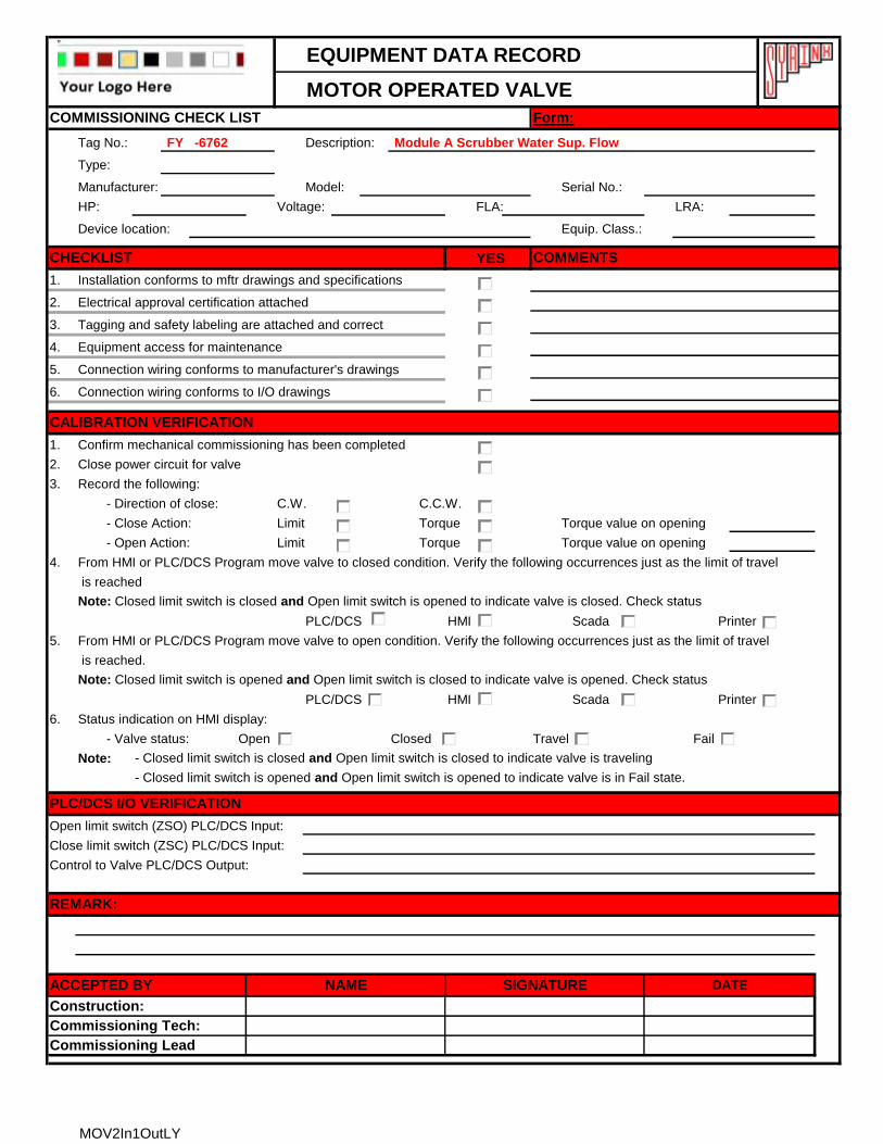
Tag No.: FY -6762 Description: Module A Scrubber Water Sup. Flow
Type:
Manufacturer: Model: Serial No.:
HP: Voltage: FLA: LRA:
Device location: Equip. Class.:
YES
1. Installation conforms to mftr drawings and specifications
2. Electrical approval certification attached
3. Tagging and safety labeling are attached and correct
4. Equipment access for maintenance
5.
6.
1. Confirm mechanical commissioning has been completed
2. Close power circuit for valve
3. Record the following:
- Direction of close: C.W. C.C.W.
- Close Action: Limit Torque Torque value on opening
- Open Action: Limit Torque Torque value on opening
4. From HMI or PLC/DCS Program move valve to closed condition. Verify the following occurrences just as the limit of travel
is reached
Note: Closed limit switch is closed and Open limit switch is opened to indicate valve is closed. Check status
PLC/DCS HMI Scada Printer
5. From HMI or PLC/DCS Program move valve to open condition. Verify the following occurrences just as the limit of travel
is reached.
Note: Closed limit switch is opened and Open limit switch is closed to indicate valve is opened. Check status
PLC/DCS HMI Scada Printer
6. Status indication on HMI display:
- Valve status: Open Closed Travel Fail
Note: - Closed limit switch is closed and Open limit switch is closed to indicate valve is traveling
- Closed limit switch is opened and Open limit switch is opened to indicate valve is in Fail state.
Open limit switch (ZSO) PLC/DCS Input:
Close limit switch (ZSC) PLC/DCS Input:
Control to Valve PLC/DCS Output:
Form:COMMISSIONING CHECK LIST
Commissioning Lead
Construction:
CHECKLIST COMMENTS
Connection wiring conforms to manufacturer's drawings
CALIBRATION VERIFICATION
Connection wiring conforms to I/O drawings
PLC/DCS I/O VERIFICATION
REMARK:
SIGNATURENAMEACCEPTED BY DATE
Commissioning Tech:
MOV2In1OutLY
EQUIPMENT DATA RECORD
MOTOR OPERATED VALVE
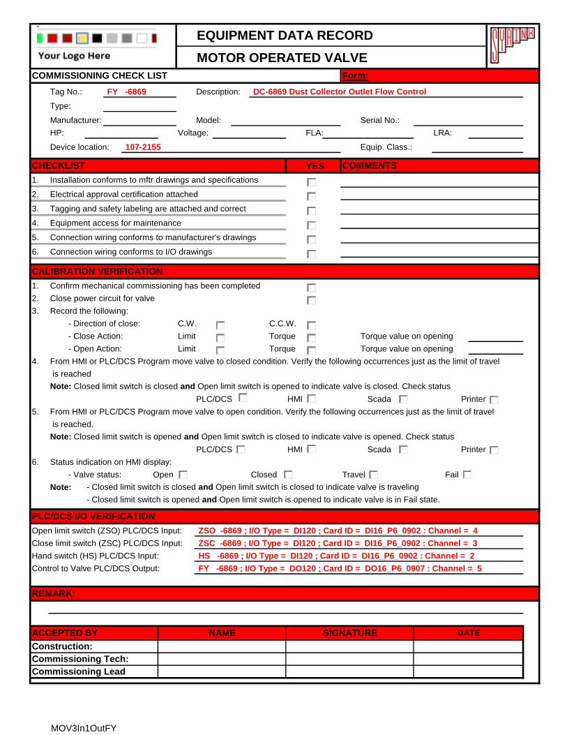
Tag No.: FY -6869 Description: DC-6869 Dust Collector Outlet Flow Control
Type:
Manufacturer: Model: Serial No.:
HP: Voltage: FLA: LRA:
Device location: 107-2155 Equip. Class.:
YES
1. Installation conforms to mftr drawings and specifications
2. Electrical approval certification attached
3. Tagging and safety labeling are attached and correct
4. Equipment access for maintenance
5.
6.
1. Confirm mechanical commissioning has been completed
2. Close power circuit for valve
3. Record the following:
- Direction of close: C.W. C.C.W.
- Close Action: Limit Torque Torque value on opening
- Open Action: Limit Torque Torque value on opening
4. From HMI or PLC/DCS Program move valve to closed condition. Verify the following occurrences just as the limit of travel
is reached
Note: Closed limit switch is closed and Open limit switch is opened to indicate valve is closed. Check status
PLC/DCS HMI Scada Printer
5. From HMI or PLC/DCS Program move valve to open condition. Verify the following occurrences just as the limit of travel
is reached.
Note: Closed limit switch is opened and Open limit switch is closed to indicate valve is opened. Check status
PLC/DCS HMI Scada Printer
6. Status indication on HMI display:
- Valve status: Open Closed Travel Fail
Note: - Closed limit switch is closed and Open limit switch is closed to indicate valve is traveling
- Closed limit switch is opened and Open limit switch is opened to indicate valve is in Fail state.
Open limit switch (ZSO) PLC/DCS Input: ZSO -6869 ; I/O Type = DI120 ; Card ID = DI16_P6_0902 : Channel = 4
Close limit switch (ZSC) PLC/DCS Input: ZSC -6869 ; I/O Type = DI120 ; Card ID = DI16_P6_0902 : Channel = 3
Hand switch (HS) PLC/DCS Input: HS -6869 ; I/O Type = DI120 ; Card ID = DI16_P6_0902 : Channel = 2
Control to Valve PLC/DCS Output: FY -6869 ; I/O Type = DO120 ; Card ID = DO16_P6_0907 : Channel = 5
Form:COMMISSIONING CHECK LIST
Commissioning Lead
Construction:
CHECKLIST COMMENTS
Connection wiring conforms to manufacturer's drawings
CALIBRATION VERIFICATION
Connection wiring conforms to I/O drawings
PLC/DCS I/O VERIFICATION
REMARK:
SIGNATURENAMEACCEPTED BY DATE
Commissioning Tech:
MOV3In1OutFY
EQUIPMENT DATA RECORD
ACTUATED VALVE WITH LIMIT SWITCHES
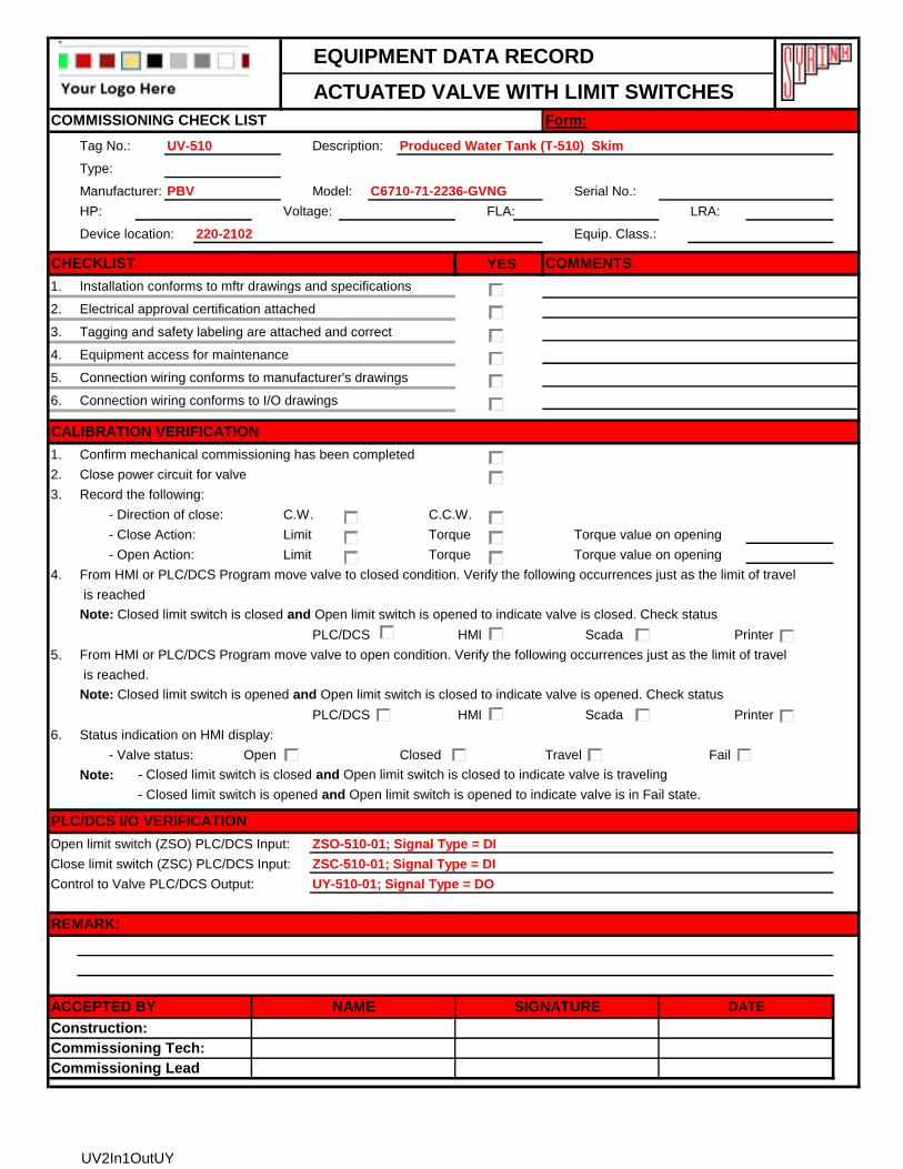
Tag No.: UV-510 Description: Produced Water Tank (T-510) Skim
Type:
Manufacturer: PBV Model: C6710-71-2236-GVNG Serial No.:
HP: Voltage: FLA: LRA:
Device location: 220-2102 Equip. Class.:
YES
1. Installation conforms to mftr drawings and specifications
2. Electrical approval certification attached
3. Tagging and safety labeling are attached and correct
4. Equipment access for maintenance
5.
6.
1. Confirm mechanical commissioning has been completed
2. Close power circuit for valve
3. Record the following:
- Direction of close: C.W. C.C.W.
- Close Action: Limit Torque Torque value on opening
- Open Action: Limit Torque Torque value on opening
4. From HMI or PLC/DCS Program move valve to closed condition. Verify the following occurrences just as the limit of travel
is reached
Note: Closed limit switch is closed and Open limit switch is opened to indicate valve is closed. Check status
PLC/DCS HMI Scada Printer
5. From HMI or PLC/DCS Program move valve to open condition. Verify the following occurrences just as the limit of travel
is reached.
Note: Closed limit switch is opened and Open limit switch is closed to indicate valve is opened. Check status
PLC/DCS HMI Scada Printer
6. Status indication on HMI display:
- Valve status: Open Closed Travel Fail
Note: - Closed limit switch is closed and Open limit switch is closed to indicate valve is traveling
- Closed limit switch is opened and Open limit switch is opened to indicate valve is in Fail state.
Open limit switch (ZSO) PLC/DCS Input: ZSO-510-01; Signal Type = DI
Close limit switch (ZSC) PLC/DCS Input: ZSC-510-01; Signal Type = DI
Control to Valve PLC/DCS Output: UY-510-01; Signal Type = DO
COMMISSIONING CHECK LIST Form:
CHECKLIST COMMENTS
Connection wiring conforms to manufacturer's drawings
Connection wiring conforms to I/O drawings
CALIBRATION VERIFICATION
PLC/DCS I/O VERIFICATION
REMARK:
ACCEPTED BY NAME SIGNATURE DATE
Commissioning Lead
Construction:
Commissioning Tech:
UV2In1OutUY
EQUIPMENT DATA RECORD
LOW VOLTAGE MOTOR WITHOUT VFD
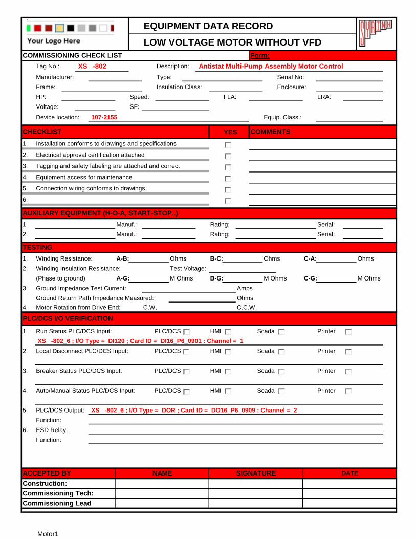
Tag No.: XS -802 Description: Antistat Multi-Pump Assembly Motor Control
Manufacturer: Type: Serial No:
Frame: Insulation Class: Enclosure:
HP: Speed: FLA: LRA:
Voltage: SF:
Device location: 107-2155 Equip. Class.:
YES
1. Installation conforms to drawings and specifications
2. Electrical approval certification attached
3. Tagging and safety labeling are attached and correct
4. Equipment access for maintenance
5.
6.
1. Manuf.: Rating: Serial:
2. Manuf.: Rating: Serial:
1. Winding Resistance: A-B: Ohms B-C: Ohms C-A: Ohms
2. Winding Insulation Resistance: Test Voltage:
(Phase to ground) A-G: M Ohms B-G: M Ohms C-G: M Ohms
3. Ground Impedance Test Current: Amps
Ground Return Path Impedance Measured: Ohms
4. Motor Rotation from Drive End: C.W. C.C.W.
1. PLC/DCS HMI Scada Printer
XS -802_6 ; I/O Type = DI120 ; Card ID = DI16_P6_0901 : Channel = 1
2. PLC/DCS HMI Scada Printer
3. PLC/DCS HMI Scada Printer
4. PLC/DCS HMI Scada Printer
5.
6.
Run Status PLC/DCS Input:
COMMISSIONING CHECK LIST
Connection wiring conforms to drawings
Form:
CHECKLIST
Local Disconnect PLC/DCS Input:
TESTING
AUXILIARY EQUIPMENT (H-O-A, START-STOP..)
Breaker Status PLC/DCS Input:
ESD Relay:
PLC/DCS I/O VERIFICATION
Commissioning Lead
ACCEPTED BY
Construction:
NAME
COMMENTS
Function:
DATE
Commissioning Tech:
SIGNATURE
Auto/Manual Status PLC/DCS Input:
PLC/DCS Output: XS -802_6 ; I/O Type = DOR ; Card ID = DO16_P6_0909 : Channel = 2
Function:
Motor1
EQUIPMENT DATA RECORD
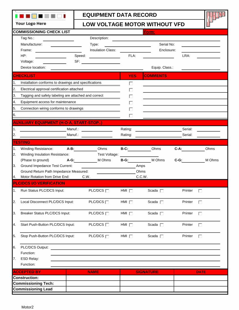
LOW VOLTAGE MOTOR WITHOUT VFD
Tag No.: Description:
Manufacturer: Type: Serial No:
Frame: Insulation Class: Enclosure:
HP: Speed: FLA: LRA:
Voltage: SF:
Device location: Equip. Class.:
YES
1. Installation conforms to drawings and specifications
2. Electrical approval certification attached
3. Tagging and safety labeling are attached and correct
4. Equipment access for maintenance
5.
6.
1. Manuf.: Rating: Serial:
2. Manuf.: Rating: Serial:
1. Winding Resistance: A-B: Ohms B-C: Ohms C-A: Ohms
2. Winding Insulation Resistance: Test Voltage:
(Phase to ground) A-G: M Ohms B-G: M Ohms C-G: M Ohms
3. Ground Impedance Test Current: Amps
Ground Return Path Impedance Measured: Ohms
4. Motor Rotation from Drive End: C.W. C.C.W.
1. PLC/DCS HMI Scada Printer
2. PLC/DCS HMI Scada Printer
3. PLC/DCS HMI Scada Printer
4. PLC/DCS HMI Scada Printer
5. PLC/DCS HMI Scada Printer
6.
7.
Function:
ESD Relay:
TESTING
AUXILIARY EQUIPMENT (H-O-A, START-STOP..)
Function:
Local Disconnect PLC/DCS Input:
Breaker Status PLC/DCS Input:
PLC/DCS Output:
Start Push-Button PLC/DCS Input:
Stop Push-Button PLC/DCS Input:
DATE
COMMENTS
PLC/DCS I/O VERIFICATION
Commissioning Tech:
SIGNATURE
Commissioning Lead
ACCEPTED BY
Construction:
NAME
Run Status PLC/DCS Input:
Connection wiring conforms to drawings
Form:COMMISSIONING CHECK LIST
CHECKLIST
Motor2
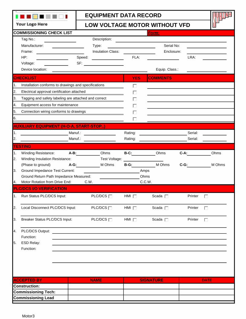
EQUIPMENT DATA RECORD
LOW VOLTAGE MOTOR WITHOUT VFD
Tag No.: Description:
Manufacturer: Type: Serial No:
Frame: Insulation Class: Enclosure:
HP: Speed: FLA: LRA:
Voltage: SF:
Device location: Equip. Class.:
YES
1. Installation conforms to drawings and specifications
2. Electrical approval certification attached
3. Tagging and safety labeling are attached and correct
4. Equipment access for maintenance
5.
6.
1. Manuf.: Rating: Serial:
2. Manuf.: Rating: Serial:
1. Winding Resistance: A-B: Ohms B-C: Ohms C-A: Ohms
2. Winding Insulation Resistance: Test Voltage:
(Phase to ground) A-G: M Ohms B-G: M Ohms C-G: M Ohms
3. Ground Impedance Test Current: Amps
Ground Return Path Impedance Measured: Ohms
4. Motor Rotation from Drive End: C.W. C.C.W.
1. PLC/DCS HMI Scada Printer
2. PLC/DCS HMI Scada Printer
3. PLC/DCS HMI Scada Printer
4.
5.
Function:
ESD Relay:
Connection wiring conforms to drawings
Breaker Status PLC/DCS Input:
PLC/DCS Output:
DATE
PLC/DCS I/O VERIFICATION
Commissioning Tech:
SIGNATURE
Function:
AUXILIARY EQUIPMENT (H-O-A, START-STOP..)
Local Disconnect PLC/DCS Input:
TESTING
Commissioning Lead
ACCEPTED BY
Construction:
NAME
Run Status PLC/DCS Input:
COMMISSIONING CHECK LIST
CHECKLIST COMMENTS
Form:
Motor3
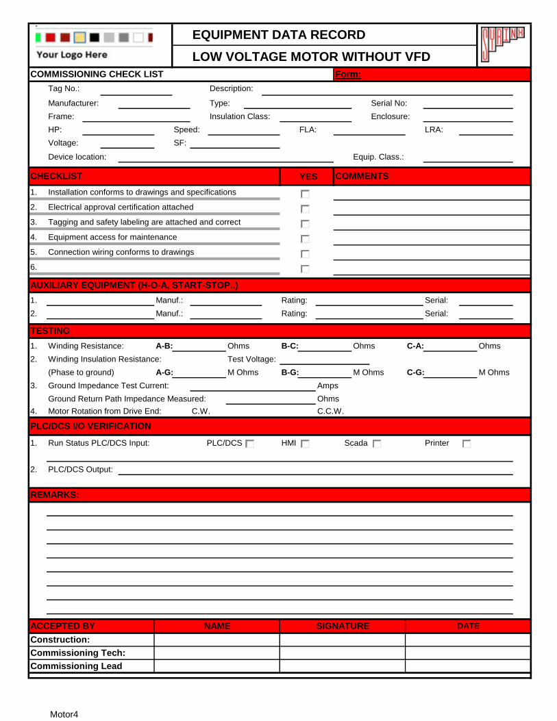
EQUIPMENT DATA RECORD
LOW VOLTAGE MOTOR WITHOUT VFD
Tag No.: Description:
Manufacturer: Type: Serial No:
Frame: Insulation Class: Enclosure:
HP: Speed: FLA: LRA:
Voltage: SF:
Device location: Equip. Class.:
YES
1. Installation conforms to drawings and specifications
2. Electrical approval certification attached
3. Tagging and safety labeling are attached and correct
4. Equipment access for maintenance
5.
6.
1. Manuf.: Rating: Serial:
2. Manuf.: Rating: Serial:
1. Winding Resistance: A-B: Ohms B-C: Ohms C-A: Ohms
2. Winding Insulation Resistance: Test Voltage:
(Phase to ground) A-G: M Ohms B-G: M Ohms C-G: M Ohms
3. Ground Impedance Test Current: Amps
Ground Return Path Impedance Measured: Ohms
4. Motor Rotation from Drive End: C.W. C.C.W.
1. PLC/DCS HMI Scada Printer
2.
REMARKS:
DATESIGNATURE
Run Status PLC/DCS Input:
Connection wiring conforms to drawings
Form:
PLC/DCS I/O VERIFICATION
AUXILIARY EQUIPMENT (H-O-A, START-STOP..)
COMMISSIONING CHECK LIST
Commissioning Lead
ACCEPTED BY
Construction:
NAME
Commissioning Tech:
CHECKLIST COMMENTS
TESTING
PLC/DCS Output:
Motor4
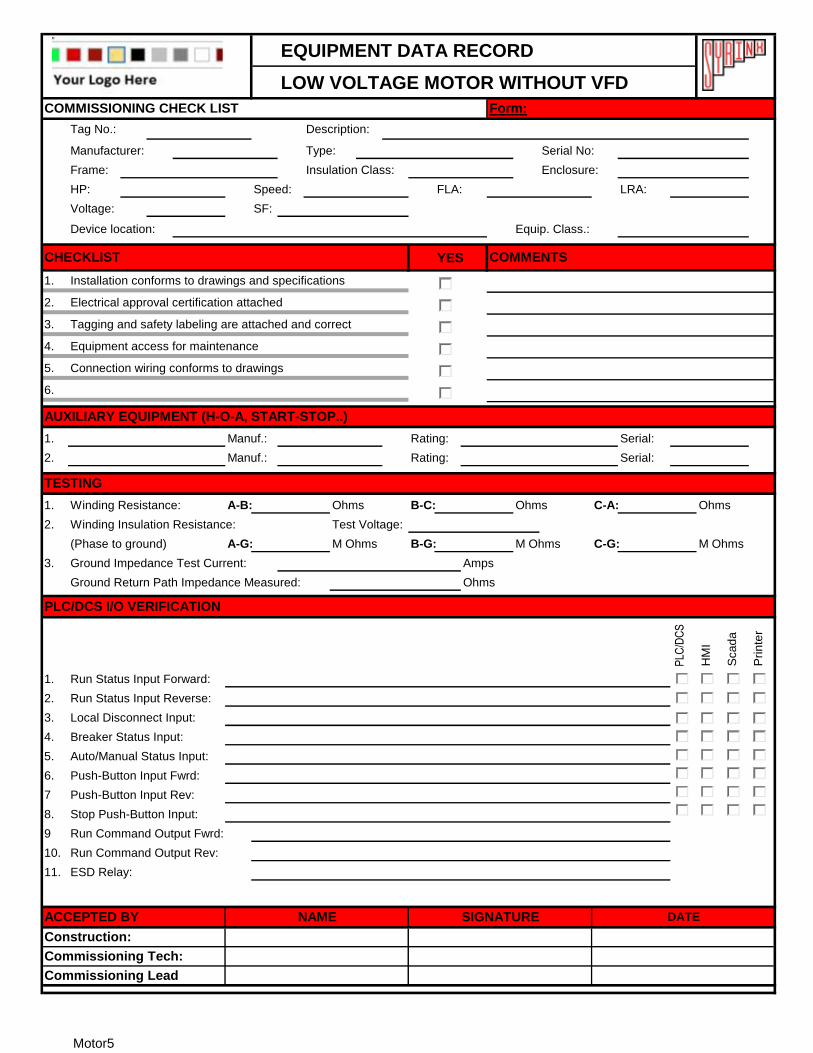
EQUIPMENT DATA RECORD
LOW VOLTAGE MOTOR WITHOUT VFD
Tag No.: Description:
Manufacturer: Type: Serial No:
Frame: Insulation Class: Enclosure:
HP: Speed: FLA: LRA:
Voltage: SF:
Device location: Equip. Class.:
YES
1. Installation conforms to drawings and specifications
2. Electrical approval certification attached
3. Tagging and safety labeling are attached and correct
4. Equipment access for maintenance
5.
6.
1. Manuf.: Rating: Serial:
2. Manuf.: Rating: Serial:
1. Winding Resistance: A-B: Ohms B-C: Ohms C-A: Ohms
2. Winding Insulation Resistance: Test Voltage:
(Phase to ground) A-G: M Ohms B-G: M Ohms C-G: M Ohms
3. Ground Impedance Test Current: Amps
Ground Return Path Impedance Measured: Ohms
PLC
/DC
S
HM
I
Sca
da
Pri
nte
r
1. Run Status Input Forward:
2. Run Status Input Reverse:
3. Local Disconnect Input:
4. Breaker Status Input:
5. Auto/Manual Status Input:
6. Push-Button Input Fwrd:
7 Push-Button Input Rev:
8. Stop Push-Button Input:
9
10.
11.
Run Command Output Fwrd:
Run Command Output Rev:
TESTING
AUXILIARY EQUIPMENT (H-O-A, START-STOP..)
DATE
PLC/DCS I/O VERIFICATION
Commissioning Tech:
SIGNATURE
ESD Relay:
Commissioning Lead
ACCEPTED BY
Construction:
NAME
Connection wiring conforms to drawings
Form:COMMISSIONING CHECK LIST
CHECKLIST COMMENTS
Motor5

EQUIPMENT DATA RECORD
LOW VOLTAGE MOTOR WITHOUT VFD
Tag No.: Description:
Manufacturer: Type: Serial No:
Frame: Insulation Class: Enclosure:
HP: Speed: FLA: LRA:
Voltage: SF:
Device location: Equip. Class.:
YES
1. Installation conforms to drawings and specifications
2. Electrical approval certification attached
3. Tagging and safety labeling are attached and correct
4. Equipment access for maintenance
5.
6.
1. Manuf.: Rating: Serial:
2. Manuf.: Rating: Serial:
1. Winding Resistance: A-B: Ohms B-C: Ohms C-A: Ohms
2. Winding Insulation Resistance: Test Voltage:
(Phase to ground) A-G: M Ohms B-G: M Ohms C-G: M Ohms
3. Ground Impedance Test Current: Amps
Ground Return Path Impedance Measured: Ohms
PLC
/DC
S
HM
I
Sca
da
Pri
nte
r
1. Run Status Input Up:
2. Run Status Input Down:
3. Local Disconnect Input:
4. Breaker Status Input:
5. Auto/Manual Status Input:
6. Push-Button Input Up:
7 Push-Button Input Down:
8. Stop Push-Button Input:
9
10.
11.
Connection wiring conforms to drawings
Form:COMMISSIONING CHECK LIST
CHECKLIST COMMENTS
Commissioning Lead
ACCEPTED BY
Construction:
NAME DATE
PLC/DCS I/O VERIFICATION
Commissioning Tech:
SIGNATURE
ESD Relay:
TESTING
AUXILIARY EQUIPMENT (H-O-A, START-STOP..)
Run Command Output Up:
Run Command Output Down:
Motor6
EQUIPMENT DATA RECORD
LOW VOLTAGE MOTOR WITHOUT VFD
Tag No.: Description:
Manufacturer: Type: Serial No:
Frame: Insulation Class: Enclosure:
HP: Speed: FLA: LRA:
Voltage: SF:
Device location: Equip. Class.:
YES
1. Installation conforms to drawings and specifications
2. Electrical approval certification attached
3. Tagging and safety labeling are attached and correct
4. Equipment access for maintenance
5.
6.
1. Manuf.: Rating: Serial:
2. Manuf.: Rating: Serial:
1. Winding Resistance: A-B: Ohms B-C: Ohms C-A: Ohms
2. Winding Insulation Resistance: Test Voltage:
(Phase to ground) A-G: M Ohms B-G: M Ohms C-G: M Ohms
3. Ground Impedance Test Current: Amps
Ground Return Path Impedance Measured: Ohms
4. Motor Rotation from Drive End: C.W. C.C.W.
1. PLC/DCS HMI Scada Printer
2. PLC/DCS HMI Scada Printer
3.
4.
Form:
NAME DATE
Run Status PLC/DCS Input:
COMMISSIONING CHECK LIST
CHECKLIST COMMENTS
PLC/DCS I/O VERIFICATION
Commissioning Lead
ACCEPTED BY
Construction:
Function:
Commissioning Tech:
SIGNATURE
Function:
ESD Relay:
Connection wiring conforms to drawings
PLC/DCS Output:
DC Motor Speed Cntrl PLC/DCS Outnput:
AUXILIARY EQUIPMENT (H-O-A, START-STOP..)
TESTING
Motor7
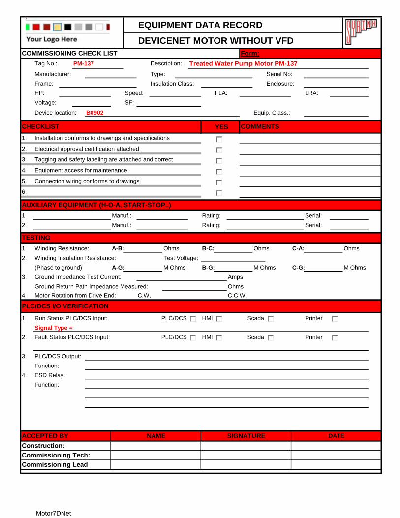
EQUIPMENT DATA RECORD
DEVICENET MOTOR WITHOUT VFD
Tag No.: PM-137 Description: Treated Water Pump Motor PM-137
Manufacturer: Type: Serial No:
Frame: Insulation Class: Enclosure:
HP: Speed: FLA: LRA:
Voltage: SF:
Device location: B0902 Equip. Class.:
YES
1. Installation conforms to drawings and specifications
2. Electrical approval certification attached
3. Tagging and safety labeling are attached and correct
4. Equipment access for maintenance
5.
6.
1. Manuf.: Rating: Serial:
2. Manuf.: Rating: Serial:
1. Winding Resistance: A-B: Ohms B-C: Ohms C-A: Ohms
2. Winding Insulation Resistance: Test Voltage:
(Phase to ground) A-G: M Ohms B-G: M Ohms C-G: M Ohms
3. Ground Impedance Test Current: Amps
Ground Return Path Impedance Measured: Ohms
4. Motor Rotation from Drive End: C.W. C.C.W.
1. PLC/DCS HMI Scada Printer
Signal Type =
2. PLC/DCS HMI Scada Printer
3.
4. ESD Relay:
Function:
COMMISSIONING CHECK LIST Form:
CHECKLIST COMMENTS
Connection wiring conforms to drawings
Function:
AUXILIARY EQUIPMENT (H-O-A, START-STOP..)
TESTING
PLC/DCS I/O VERIFICATION
Run Status PLC/DCS Input:
Fault Status PLC/DCS Input:
PLC/DCS Output:
ACCEPTED BY NAME SIGNATURE DATE
Construction:
Commissioning Tech:
Commissioning Lead
Motor7DNet
EQUIPMENT DATA RECORD
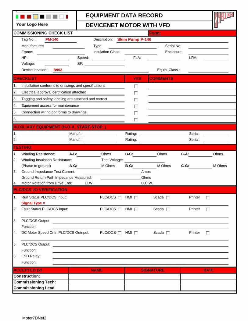
DEVICENET MOTOR WITH VFD
Tag No.: PM-140 Description: Skim Pump P-140
Manufacturer: Type: Serial No:
Frame: Insulation Class: Enclosure:
HP: Speed: FLA: LRA:
Voltage: SF:
Device location: B902 Equip. Class.:
YES
1. Installation conforms to drawings and specifications
2. Electrical approval certification attached
3. Tagging and safety labeling are attached and correct
4. Equipment access for maintenance
5.
6.
1. Manuf.: Rating: Serial:
2. Manuf.: Rating: Serial:
1. Winding Resistance: A-B: Ohms B-C: Ohms C-A: Ohms
2. Winding Insulation Resistance: Test Voltage:
(Phase to ground) A-G: M Ohms B-G: M Ohms C-G: M Ohms
3. Ground Impedance Test Current: Amps
Ground Return Path Impedance Measured: Ohms
4. Motor Rotation from Drive End: C.W. C.C.W.
1. PLC/DCS HMI Scada Printer
Signal Type =
2. PLC/DCS HMI Scada Printer
3.
4. PLC/DCS HMI Scada Printer
5.
6. ESD Relay:
Function:
COMMISSIONING CHECK LIST Form:
CHECKLIST COMMENTS
Connection wiring conforms to drawings
DATE
AUXILIARY EQUIPMENT (H-O-A, START-STOP..)
TESTING
PLC/DCS I/O VERIFICATION
Run Status PLC/DCS Input:
Fault Status PLC/DCS Input:
PLC/DCS Output:
Function:
DC Motor Speed Cntrl PLC/DCS Outnput:
PLC/DCS Output:
Function:
ACCEPTED BY NAME SIGNATURE
Commissioning Lead
Construction:
Commissioning Tech:
Motor7DNet2
EQUIPMENT DATA RECORD
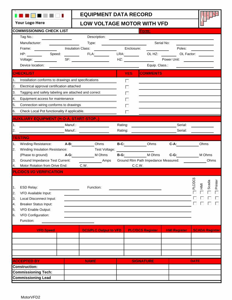
LOW VOLTAGE MOTOR WITH VFD
Tag No.: Description:
Manufacturer: Type: Serial No:
Frame: Insulation Class: Enclosure: Poles:
HP: Speed: FLA: LRA: OL HZ: OL Factor:
Voltage: SF: HZ: Power Unit:
Device location: Equip. Class.:
YES
1. Installation conforms to drawings and specifications
2. Electrical approval certification attached
3. Tagging and safety labeling are attached and correct
4. Equipment access for maintenance
5.
6. Check Local Pot functionality if applicable.
1. Manuf.: Rating: Serial:
2. Manuf.: Rating: Serial:
1. Winding Resistance: A-B: Ohms B-C: Ohms C-A: Ohms
2. Winding Insulation Resistance: Test Voltage:
(Phase to ground) A-G: M Ohms B-G: M Ohms C-G: M Ohms
3. Ground Impedance Test Current: Amps Ground Rtrn Path Impedance Measured: Ohms
4. Motor Rotation from Drive End: C.W. C.C.W.
1. ESD Relay: Function: PLC
/DC
S
HM
I
Sca
da
Pri
nte
r
2. VFD Available Input:
3. Local Disconnect Input:
4. Breaker Status Input:
5. Auto/Manual Status Input:
6. VFD Enable Output:
7. VFD Configuration:
Function:
Connection wiring conforms to drawings
Form:
Commissioning Lead
ACCEPTED BY
Construction:
NAME DATE
PLC/DCS I/O VERIFICATION
Commissioning Tech:
SIGNATURE
TESTING
AUXILIARY EQUIPMENT (H-O-A, START-STOP..)
COMMISSIONING CHECK LIST
CHECKLIST COMMENTS
SCADA RegisterPLC/DCS Register HMI RegisterVFD Speed DCS/PLC Output to VFD
MotorVFD
EQUIPMENT DATA RECORD
LOW VOLTAGE MOTOR WITH VFD
Tag No.: Description:
Manufacturer: Type: Serial No:
Frame: Insulation Class: Enclosure: Poles:
HP: Speed: FLA: LRA: OL HZ: OL Factor:
Voltage: SF: HZ: Power Unit:
Device location: Equip. Class.:
YES
1. Installation conforms to drawings and specifications
2. Electrical approval certification attached
3. Tagging and safety labeling are attached and correct
4. Equipment access for maintenance
5.
6. Check Local Pot functionality if applicable.
1. Manuf.: Rating: Serial:
2. Manuf.: Rating: Serial:
1. Winding Resistance: A-B: Ohms B-C: Ohms C-A: Ohms
2. Winding Insulation Resistance: Test Voltage:
(Phase to ground) A-G: M Ohms B-G: M Ohms C-G: M Ohms
3. Ground Impedance Test Current: Amps Ground Rtrn Path Impedance Measured: Ohms
4. Motor Rotation from Drive End: C.W. C.C.W.
1. ESD Relay: Function: PLC
/DC
S
HM
I
Sca
da
Pri
nte
r
2. VFD Available Input:
3. Local Disconnect Input:
4. Breaker Status Input:
5. VFD Enable Output:
6. VFD Configuration:
Function:
TESTING
AUXILIARY EQUIPMENT (H-O-A, START-STOP..)
VFD Speed DCS/PLC Output to VFD PLC/DCS Register HMI Register
Commissioning Tech:
SIGNATURE
Commissioning Lead
ACCEPTED BY
Connection wiring conforms to drawings
Form:
SCADA Register
NAME DATE
COMMISSIONING CHECK LIST
CHECKLIST COMMENTS
Construction:
PLC/DCS I/O VERIFICATION
MotorVFD2
EQUIPMENT DATA RECORD
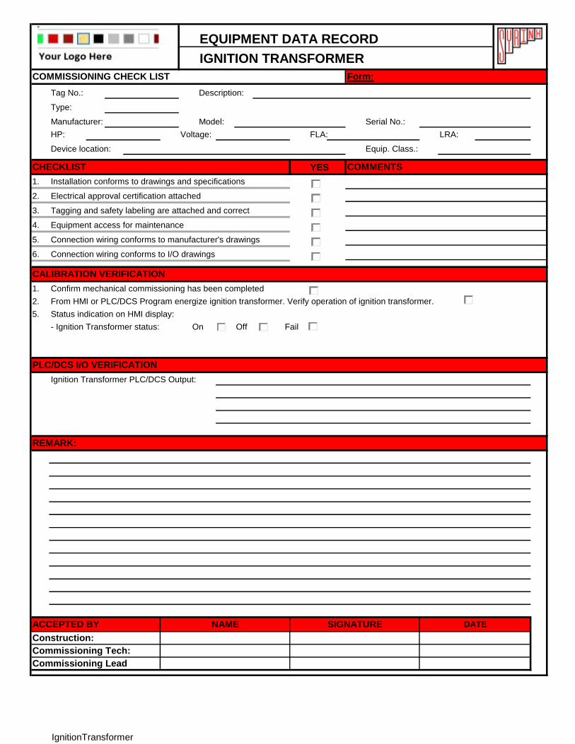
IGNITION TRANSFORMER
Tag No.: Description:
Type:
Manufacturer: Model: Serial No.:
HP: Voltage: FLA: LRA:
Device location: Equip. Class.:
YES
1. Installation conforms to drawings and specifications
2. Electrical approval certification attached
3. Tagging and safety labeling are attached and correct
4. Equipment access for maintenance
5.
6.
1. Confirm mechanical commissioning has been completed
2. From HMI or PLC/DCS Program energize ignition transformer. Verify operation of ignition transformer.
5. Status indication on HMI display:
On Off Fail
Ignition Transformer PLC/DCS Output:
COMMISSIONING CHECK LIST
PLC/DCS I/O VERIFICATION
REMARK:
SIGNATUREACCEPTED BY
CHECKLIST COMMENTS
Construction:
Form:
CALIBRATION VERIFICATION
Connection wiring conforms to manufacturer's drawings
Connection wiring conforms to I/O drawings
- Ignition Transformer status:
NAME DATE
Commissioning Tech:
Commissioning Lead
IgnitionTransformer
EQUIPMENT DATA RECORD
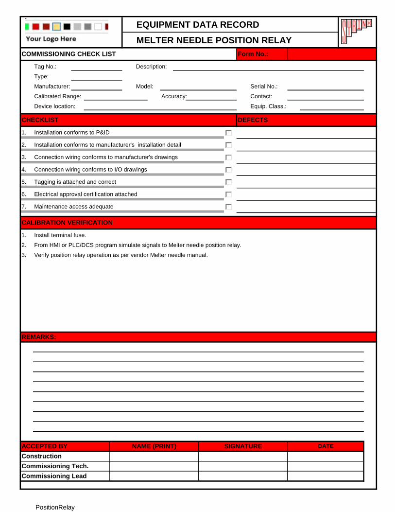
MELTER NEEDLE POSITION RELAY
Tag No.: Description:
Type:
Manufacturer: Model: Serial No.:
Calibrated Range: Accuracy: Contact:
Device location: Equip. Class.:
1.
2.
3.
4.
5.
6.
7.
1.
2.
3.
REMARKS:
Commissioning Lead
Commissioning Tech.
Construction
ACCEPTED BY NAME (PRINT) SIGNATURE DATE
COMMISSIONING CHECK LIST Form No.:
Installation conforms to P&ID
Installation conforms to manufacturer's installation detail
Connection wiring conforms to manufacturer's drawings
DEFECTSCHECKLIST
Connection wiring conforms to I/O drawings
Tagging is attached and correct
Electrical approval certification attached
From HMI or PLC/DCS program simulate signals to Melter needle position relay.
CALIBRATION VERIFICATION
Maintenance access adequate
Verify position relay operation as per vendor Melter needle manual.
Install terminal fuse.
PositionRelay
EQUIPMENT DATA RECORD
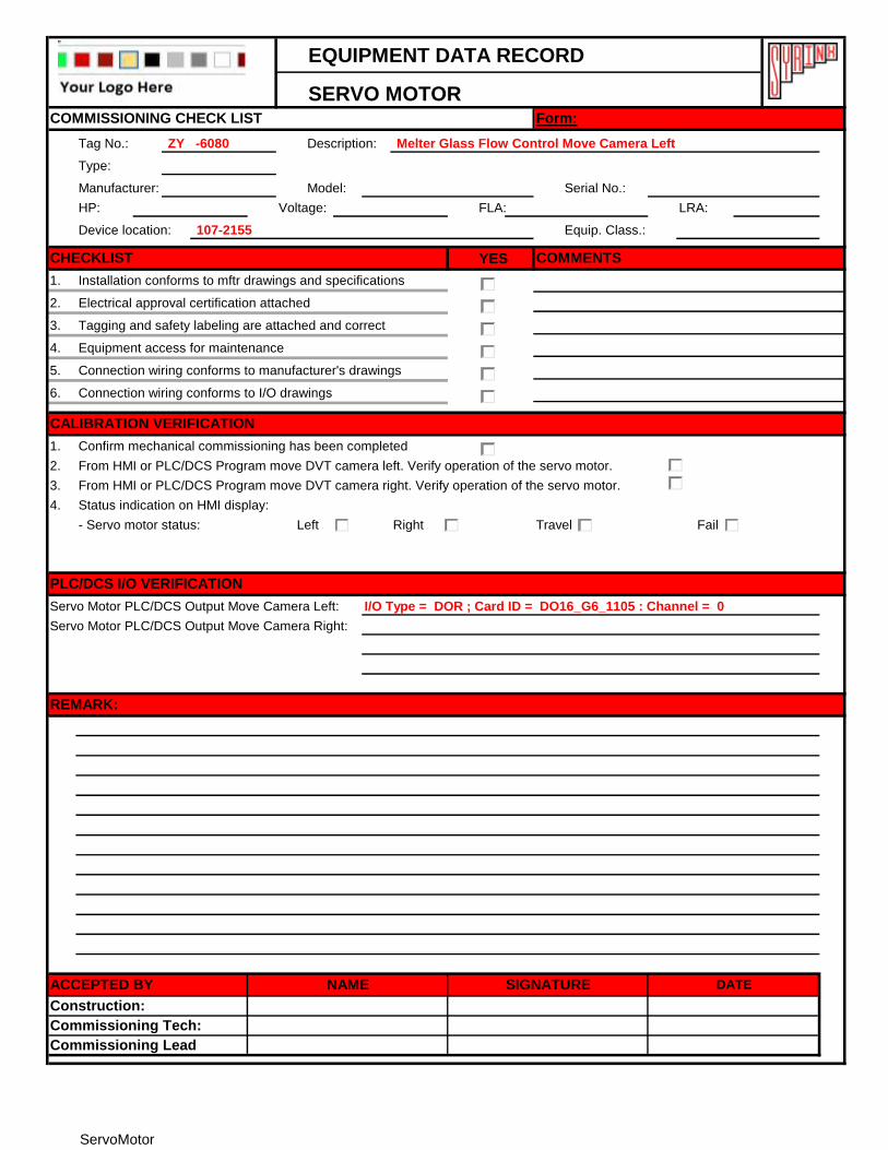
SERVO MOTOR
Tag No.: ZY -6080 Description: Melter Glass Flow Control Move Camera Left
Type:
Manufacturer: Model: Serial No.:
HP: Voltage: FLA: LRA:
Device location: 107-2155 Equip. Class.:
YES
1. Installation conforms to mftr drawings and specifications
2. Electrical approval certification attached
3. Tagging and safety labeling are attached and correct
4. Equipment access for maintenance
5.
6.
1. Confirm mechanical commissioning has been completed
2. From HMI or PLC/DCS Program move DVT camera left. Verify operation of the servo motor.
3. From HMI or PLC/DCS Program move DVT camera right. Verify operation of the servo motor.
4. Status indication on HMI display:
Left Right Travel Fail
Servo Motor PLC/DCS Output Move Camera Left: I/O Type = DOR ; Card ID = DO16_G6_1105 : Channel = 0
Servo Motor PLC/DCS Output Move Camera Right:
COMMISSIONING CHECK LIST
PLC/DCS I/O VERIFICATION
REMARK:
SIGNATUREACCEPTED BY
CHECKLIST COMMENTS
Construction:
Form:
CALIBRATION VERIFICATION
Connection wiring conforms to manufacturer's drawings
Connection wiring conforms to I/O drawings
- Servo motor status:
NAME DATE
Commissioning Tech:
Commissioning Lead
ServoMotor
EQUIPMENT DATA RECORD
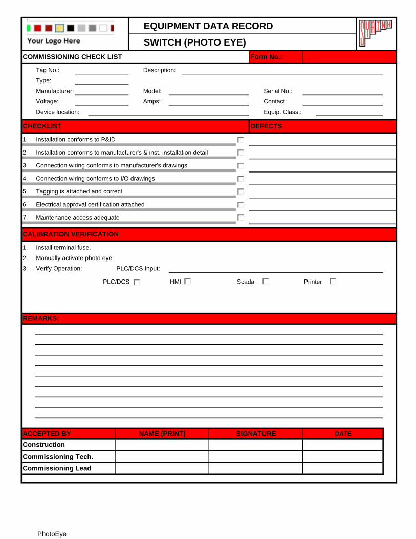
SWITCH (PHOTO EYE)
Tag No.: Description:
Type:
Manufacturer: Model: Serial No.:
Voltage: Amps: Contact:
Device location: Equip. Class.:
1.
2.
3.
4.
5.
6.
7.
1.
2.
3. Verify Operation: PLC/DCS Input:
PLC/DCS HMI Scada Printer
Install terminal fuse.
Manually activate photo eye.
Commissioning Tech.
Commissioning Lead
ACCEPTED BY NAME (PRINT) SIGNATURE DATE
Construction
CALIBRATION VERIFICATION
COMMISSIONING CHECK LIST
Electrical approval certification attached
Installation conforms to manufacturer's & inst. installation detail
Connection wiring conforms to manufacturer's drawings
Form No.:
Installation conforms to P&ID
DEFECTSCHECKLIST
Connection wiring conforms to I/O drawings
Tagging is attached and correct
Maintenance access adequate
REMARKS:
PhotoEye
EQUIPMENT DATA RECORD
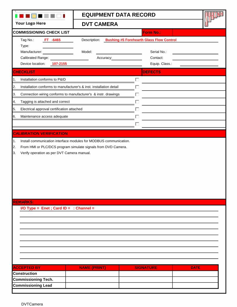
DVT CAMERA
Tag No.: FT -6465 Description: Bushing #5 Forehearth Glass Flow Control
Type:
Manufacturer: Model: Serial No.:
Calibrated Range: Accuracy: Contact:
Device location: 107-2155 Equip. Class.:
1.
2.
3.
4.
5.
6.
1.
2.
3.
I/O Type = Enet ; Card ID = : Channel =
REMARKS:
Commissioning Lead
Commissioning Tech.
Construction
ACCEPTED BY NAME (PRINT) SIGNATURE DATE
COMMISSIONING CHECK LIST Form No.:
Installation conforms to P&ID
Installation conforms to manufacturer's & inst. installation detail
Connection wiring conforms to manufacturer's & instr. drawings
DEFECTSCHECKLIST
Tagging is attached and correct
Electrical approval certification attached
Maintenance access adequate
From HMI or PLC/DCS program simulate signals from DVD Camera.
CALIBRATION VERIFICATION
Verify operation as per DVT Camera manual.
Install communication interface modules for MODBUS communication.
DVTCamera
EQUIPMENT DATA RECORD
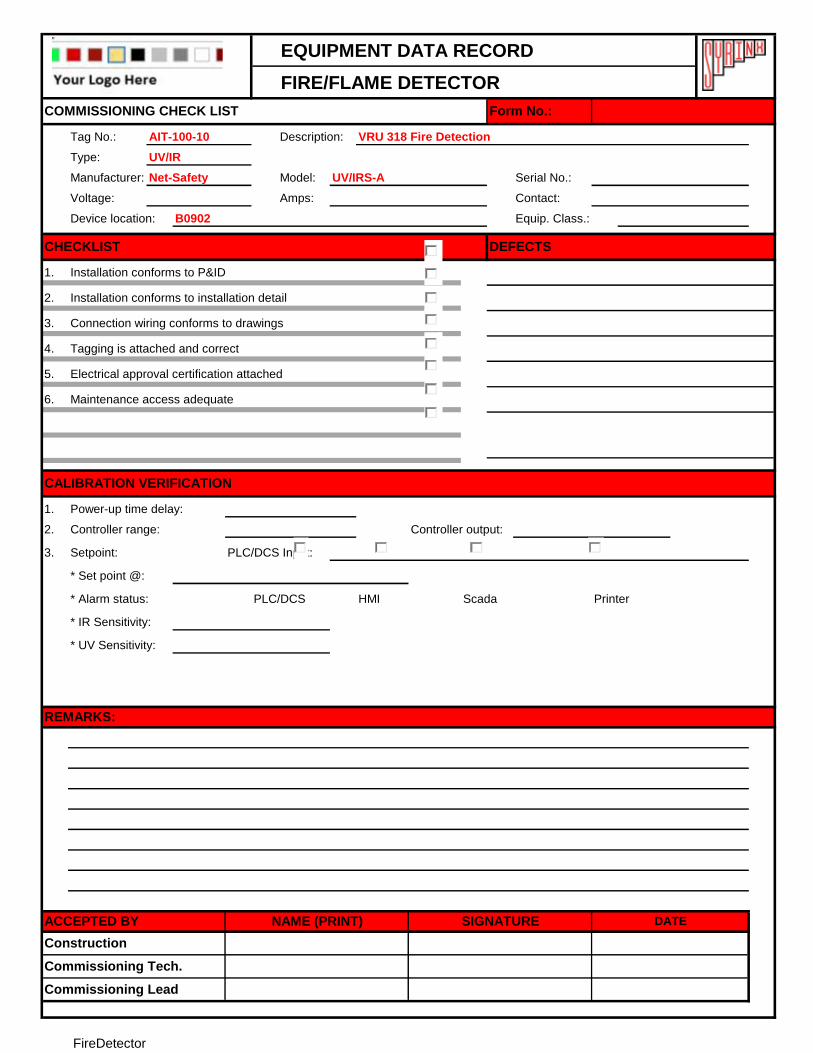
FIRE/FLAME DETECTOR
Tag No.: AIT-100-10 Description: VRU 318 Fire Detection
Type: UV/IR
Manufacturer: Net-Safety Model: UV/IRS-A Serial No.:
Voltage: Amps: Contact:
Device location: B0902 Equip. Class.:
1.
2.
3.
4.
5.
6.
1. Power-up time delay:
2. Controller range: Controller output:
3. Setpoint: PLC/DCS Input:
* Set point @:
* Alarm status: PLC/DCS HMI Scada Printer
* IR Sensitivity:
* UV Sensitivity:
REMARKS:
COMMISSIONING CHECK LIST Form No.:
Commissioning Lead
Construction
Commissioning Tech.
ACCEPTED BY NAME (PRINT) SIGNATURE DATE
Installation conforms to P&ID
Installation conforms to installation detail
Connection wiring conforms to drawings
DEFECTSCHECKLIST
Tagging is attached and correct
Electrical approval certification attached
Maintenance access adequate
CALIBRATION VERIFICATION
FireDetector
EQUIPMENT DATA RECORD
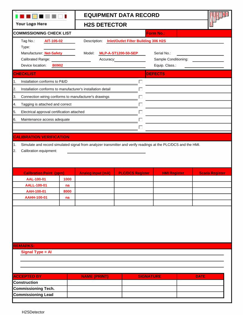
H2S DETECTOR
Tag No.: AIT-105-02 Description: Inlet/Outlet Filter Building 306 H2S
Type:
Manufacturer: Net-Safety Model: MLP-A-ST1200-50-SEP Serial No.:
Calibrated Range: Accuracy: Sample Conditioning:
Device location: B0902 Equip. Class.:
1.
2.
3.
4.
5.
6.
1.
2. Calibration equipment:
COMMISSIONING CHECK LIST Form No.:
CHECKLIST DEFECTS
Installation conforms to P&ID
Installation conforms to manufacturer's installation detail
Connection wiring conforms to manufacturer's drawings
Tagging is attached and correct
HMI Register Scada Register
Electrical approval certification attached
Maintenance access adequate
Calibration Point (ppm) Analog Input (mA)
AALL-100-01
CALIBRATION VERIFICATION
Simulate and record simulated signal from analyzer transmitter and verify readings at the PLC/DCS and the HMI.
AAH-100-01
AAHH-100-01
8000
na
REMARKS:
Signal Type = AI
Commissioning Lead
ACCEPTED BY NAME (PRINT) SIGNATURE DATE
AAL-100-01
na
Commissioning Tech.
Construction
PLC/DCS Register
1000
H2SDetector
EQUIPMENT DATA RECORD
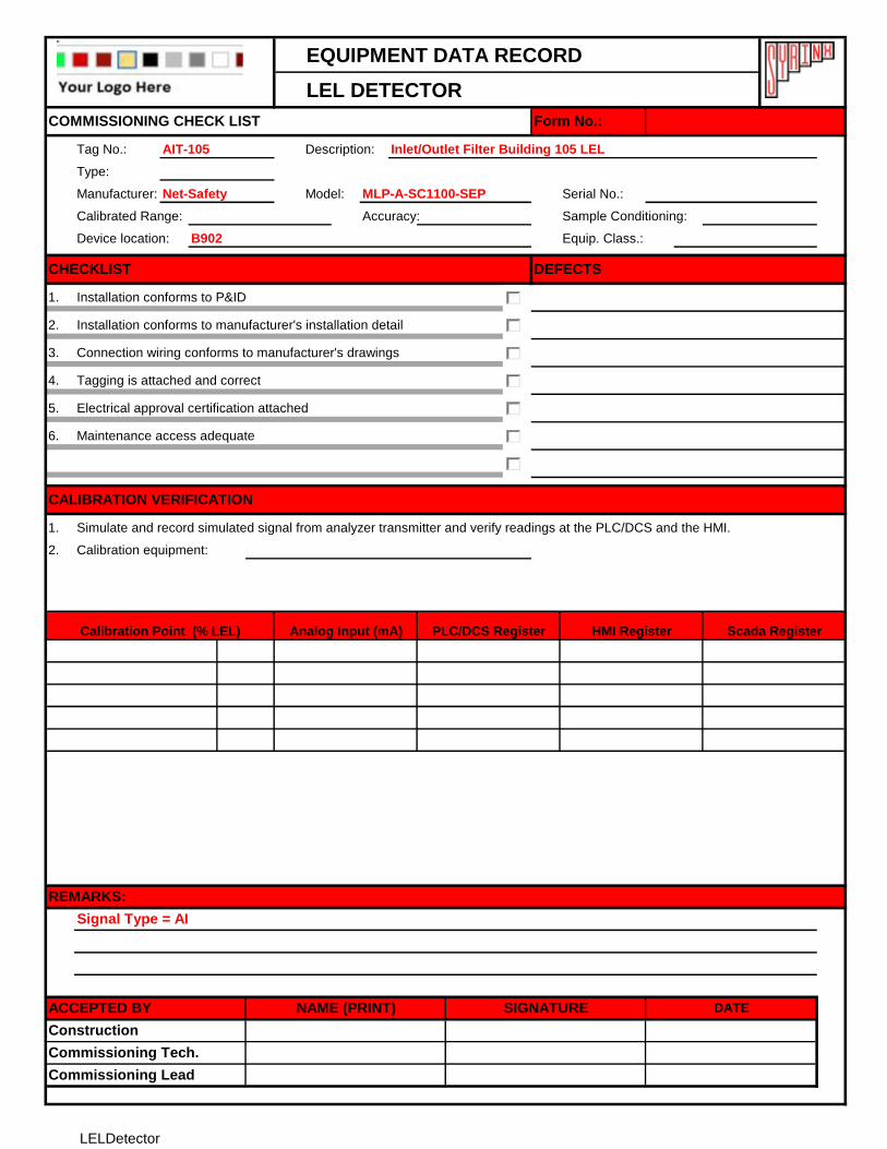
LEL DETECTOR
Tag No.: AIT-105 Description: Inlet/Outlet Filter Building 105 LEL
Type:
Manufacturer: Net-Safety Model: MLP-A-SC1100-SEP Serial No.:
Calibrated Range: Accuracy: Sample Conditioning:
Device location: B902 Equip. Class.:
1.
2.
3.
4.
5.
6.
1.
2. Calibration equipment:
COMMISSIONING CHECK LIST Form No.:
CHECKLIST DEFECTS
Installation conforms to P&ID
Installation conforms to manufacturer's installation detail
Connection wiring conforms to manufacturer's drawings
Tagging is attached and correct
HMI Register Scada Register
Electrical approval certification attached
Maintenance access adequate
Calibration Point (% LEL) Analog Input (mA)
CALIBRATION VERIFICATION
Simulate and record simulated signal from analyzer transmitter and verify readings at the PLC/DCS and the HMI.
REMARKS:
Signal Type = AI
Commissioning Lead
ACCEPTED BY NAME (PRINT) SIGNATURE DATE
Commissioning Tech.
Construction
PLC/DCS Register
LELDetector
EQUIPMENT DATA RECORD
EMERGENCY SHUT DOWN VALVE
Tag No.: Description:
Type:
Manufacturer: Model: Serial No.:
HP: Voltage: FLA: LRA:
Device location: Equip. Class.:
1.
2.
3.
4.
5.
6.
7.
1.
2.
3.
Should calibration be required, refer to Control Valve manual.
The PLC/DCS shall be checked for following
Air Failure Opens Closes Last Position
Signal Failure Opens Closes Last Position
Control to Valve PLC/DCS Output:
COMMISSIONING CHECK LIST Form No.:
CHECKLIST DEFECTS
Installation conforms to P&ID
Installation conforms to manufacturer's & inst. installation detail
Connection wiring conforms to manufacturer's drawings
Connection wiring conforms to I/O drawings
Tagging is attached and correct
Electrical approval certification attached
Maintenance access adequate
CALIBRATION VERIFICATION
Calibrate Control Valve as per Datasheet.
Connect Control Valve. Install terminal fuse.
Simulate Valve action and record indicated readings from the PLC/DCS and the HMI.
HMI Register Scada RegisterValve Position Analog Output (mA) PLC/DCS Register
REMARKS:
Close/Open
ACCEPTED BY NAME (PRINT) SIGNATURE DATE
Construction
Commissioning Tech.
Commissioning Lead
Open/Close
ESDValve
EQUIPMENT DATA RECORD
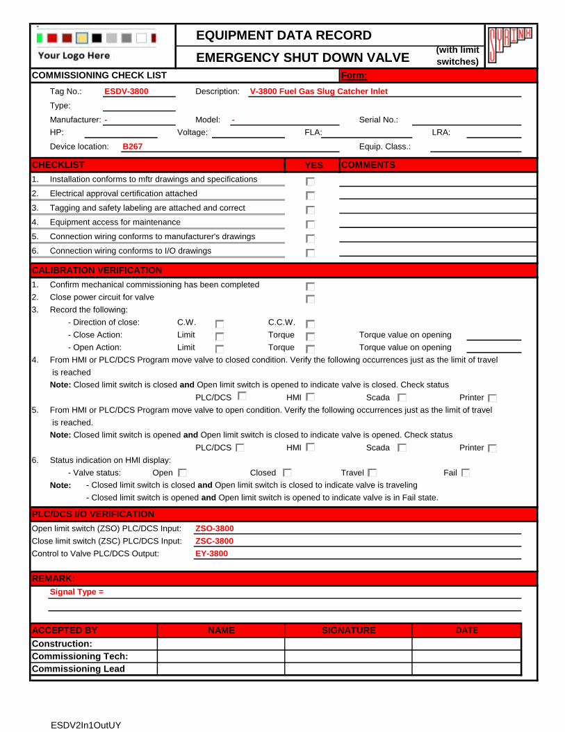
EMERGENCY SHUT DOWN VALVE
Tag No.: ESDV-3800 Description: V-3800 Fuel Gas Slug Catcher Inlet
Type:
Manufacturer: - Model: - Serial No.:
HP: Voltage: FLA: LRA:
Device location: B267 Equip. Class.:
YES
1. Installation conforms to mftr drawings and specifications
2. Electrical approval certification attached
3. Tagging and safety labeling are attached and correct
4. Equipment access for maintenance
5.
6.
1. Confirm mechanical commissioning has been completed
2. Close power circuit for valve
3. Record the following:
- Direction of close: C.W. C.C.W.
- Close Action: Limit Torque Torque value on opening
- Open Action: Limit Torque Torque value on opening
4. From HMI or PLC/DCS Program move valve to closed condition. Verify the following occurrences just as the limit of travel
is reached
Note: Closed limit switch is closed and Open limit switch is opened to indicate valve is closed. Check status
PLC/DCS HMI Scada Printer
5. From HMI or PLC/DCS Program move valve to open condition. Verify the following occurrences just as the limit of travel
is reached.
Note: Closed limit switch is opened and Open limit switch is closed to indicate valve is opened. Check status
PLC/DCS HMI Scada Printer
6. Status indication on HMI display:
- Valve status: Open Closed Travel Fail
Note: - Closed limit switch is closed and Open limit switch is closed to indicate valve is traveling
- Closed limit switch is opened and Open limit switch is opened to indicate valve is in Fail state.
Open limit switch (ZSO) PLC/DCS Input: ZSO-3800
Close limit switch (ZSC) PLC/DCS Input: ZSC-3800
Control to Valve PLC/DCS Output: EY-3800
COMMISSIONING CHECK LIST Form:
CHECKLIST COMMENTS
Connection wiring conforms to manufacturer's drawings
Connection wiring conforms to I/O drawings
CALIBRATION VERIFICATION
PLC/DCS I/O VERIFICATION
REMARK:
Signal Type =
Commissioning Tech:
ACCEPTED BY NAME SIGNATURE DATE
Commissioning Lead
(with limit
switches)
Construction:
ESDV2In1OutUY
EQUIPMENT DATA RECORD
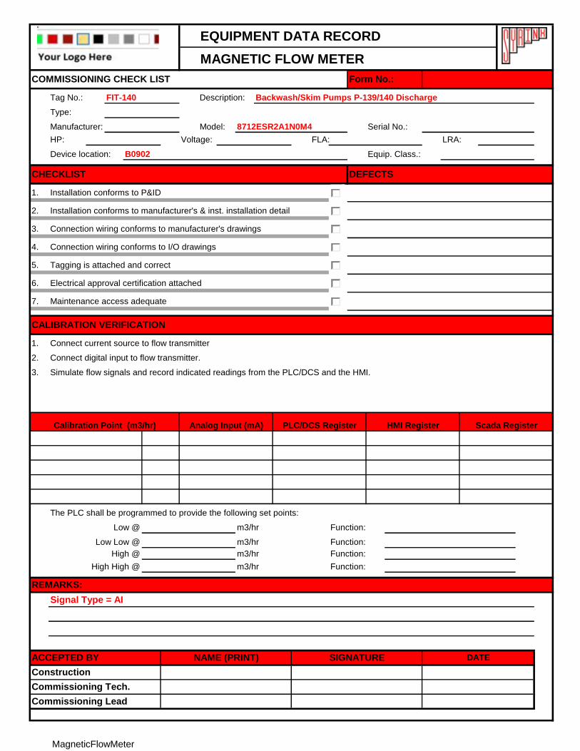
MAGNETIC FLOW METER
Tag No.: FIT-140 Description: Backwash/Skim Pumps P-139/140 Discharge
Type:
Manufacturer: Model: 8712ESR2A1N0M4 Serial No.:
HP: Voltage: FLA: LRA:
Device location: B0902 Equip. Class.:
1.
2.
3.
4.
5.
6.
7.
1.
2.
3.
The PLC shall be programmed to provide the following set points:
m3/hr Function:
m3/hr Function:
m3/hr Function:
m3/hr Function:
Signal Type = AI
COMMISSIONING CHECK LIST Form No.:
CHECKLIST DEFECTS
Installation conforms to P&ID
Installation conforms to manufacturer's & inst. installation detail
Connection wiring conforms to manufacturer's drawings
Connection wiring conforms to I/O drawings
Tagging is attached and correct
Electrical approval certification attached
Maintenance access adequate
CALIBRATION VERIFICATION
Connect current source to flow transmitter
Connect digital input to flow transmitter.
Simulate flow signals and record indicated readings from the PLC/DCS and the HMI.
HMI Register Scada RegisterCalibration Point (m3/hr) Analog Input (mA) PLC/DCS Register
REMARKS:
Low @
ACCEPTED BY NAME (PRINT) SIGNATURE DATE
Construction
Commissioning Tech.
Commissioning Lead
High High @
Low Low @
High @
MagneticFlowMeter
EQUIPMENT DATA RECORD
DIFFERENTIAL PRESSURE TRANSMITTER
Tag No.: DPIT-338 Description: Basket Strainer 500 Differentail Pressure (FUTURE)
Type:
Manufacturer: Model: (FUTURE) Serial No.:
Calibrated Range: Accuracy: Diaphragm Seal(s):
Device location: B0902 Equip. Class.:
1.
2.
3.
4.
5.
6.
7.
The PLC shall be programmed to provide the following set points:
psig Function:
psig Function:
psig Function:
psig Function:
COMMISSIONING CHECK LIST Form No.:
CHECKLIST DEFECTS
Installation conforms to P&ID
Installation conforms to manufacturer's & inst. installation detail
Connection wiring conforms to manufacturer's drawings
Connection wiring conforms to I/O drawings
Tagging is attached and correct
Electrical approval certification attached
Maintenance access adequate
CALIBRATION VERIFICATION
HMI Register Scada RegisterCalibration Point (psig) Analog Input (mA) PLC/DCS Register
Low @
Low Low @
High @
High High @
REMARKS:
Signal Type = AI
ACCEPTED BY NAME (PRINT) SIGNATURE DATE
Construction
Commissioning Tech.
Commissioning Lead
DifferentialPressureTransmitter
EQUIPMENT DATA RECORD
VIBRATION TRANSMITTER
Tag No.: VT-137 Description: Treated Water Pump P-137
Type:
Manufacturer: By Vendor Model: By Vendor Serial No.:
Calibrated Range: Accuracy: Diaphragm Seal(s):
Device location: B0902 Equip. Class.:
1.
2.
3.
4.
5.
6.
7.
The PLC shall be programmed to provide the following set points:
mm/sec Function:
mm/sec Function:
mm/sec Function:
mm/sec Function:
COMMISSIONING CHECK LIST Form No.:
CHECKLIST DEFECTS
Installation conforms to P&ID
Installation conforms to manufacturer's & inst. installation detail
Connection wiring conforms to manufacturer's drawings
Connection wiring conforms to I/O drawings
Tagging is attached and correct
Electrical approval certification attached
Maintenance access adequate
CALIBRATION VERIFICATION
HMI Register Scada RegisterCalibration Point (mm/s) Analog Input (mA) PLC/DCS Register
Low @
Low Low @
High @
High High @
REMARKS:
Signal Type = AI
ACCEPTED BY NAME (PRINT) SIGNATURE DATE
Construction
Commissioning Tech.
Commissioning Lead
VibrationTransmitter
EQUIPMENT DATA RECORD
MISCELLANEOUS
Tag No.: AY-106 Description: MCC Process Alarm Red Outside
Type:
Manufacturer: --- Model: --- Voltage: Current:
Feed from Panel: Circuit Reference: Protection Rating:
Device location: B902 Equip. Class.:
YES
.1 Installation conforms to drawings and specifications
.2 Electrical approval certification attached
.3 Tagging and safety labeling are attached and correct
.4 Equipment access for maintenance
.5 Check ground wire termination
Lighting
6. Measure voltage at termination end
7. Check operation of individual control switch
8. Measure luminous intensity
9.
Receptacle
10. Check interlock mechanism
11. Measure voltage at each outlet
12.
Attend control station (switch, push-button ..etc)
13. Check normal operation
14. Check lock-off position operation
15. Signal Type = DO
Miscellaneous (smoke detector, door switch ..etc)
16. Check normal operation
17. Device set point
18.
19.
Signal Type = E
Commissioning Lead
Commissioning Tech.
Construction
NAME (PRINT) SIGNATURE DATEACCEPTED BY
REMARKS:
COMMENTSCHECKLIST
PRE-COMMISSIONING INSPECTION CHECK LIST Form No.:
Miscellaneous