equipment for applying soil pesticides
TRANSCRIPT

EQUIPMENT for APPLYING SOIL PESTICIDES
U. $. DEPT. OF HGRlCULTUîll
MAR "^' " Ml
Agriculture Handbook No. 297
Agricultural J¡,esearch Service, Uí^ITED STATES DEPARTMENT, OF AGRICULTURE.
in cooperation with
Ohio Agricultural Research and Development Center

Contents Page
Construction materials 2 Applicator components for fluid-tjrpe pesticides 3
Tanks, agitators, and strainers 3 Fluid transfer systems 4
Gravity flow systems 4 Pneumatic and aeriform systems 6 Pumping systems 7 Fluid supply lines 7 Valves and pressure regulators 8
Components for volume control 9 Terminal distribution devices 11
Subsurface dispersion 11 Subsurface linear application 12 Results of different distribution methods 15
Fumigant retaining devices 15 Permeable fumigant retainers 15 Impermeable fumigant retainers 17
Applicator components for granular-type pesticides 19 Hoppers and metering devic<îs 19 Granular dispersal systems 20
Specialized soil pesticide applicators 20 Applicators for treating the root zone of living
plants 20 Applicators for treating tha seed zone while
planting 21 Surface incorporation 23
Methods for controlling application rates of soil pes- ticides 25
Speed of applicator 25 Flow rate of fluid pesticides 26
Calculations for applying fluids 26 Flow rate of granular pesticides 31
Calculations for applying granules 31 Cleaning applicator equipment 32 Selected references 33 Appendix 37
Pesticide chemical key 37
Washington/(D.C. Issued January 1966
For sale by the Superintendent of Documents, U.S. Government Printing Office Washington, D.C., 20402 - Price 20 cents

EQUIPMENT FOR APPLYING SOIL PESTICIDES
^By 0. K. Hedden, ^h^HeaUn-rttl ^enQ^meeVy Agricultural Research ^ermeer; J. D. Wilson, ■^ pn}0s^m^of-^büéanp~^nd pl^n-t and J. B. Sleesmany/professor of zoology
and entomology^ the Ohio Agricultural Research and Development Center and Ohio State University
Many spe<:ies of fungi, insects, and nematodes are in the soil at population levels that are detrimen- tal to crops {11, 23, 32, 52, 69)} Soil pesticides destroy some of these pests and may also destroy the viability of the seed of some weeds.
Some soil pesticides are tolerated by living plants, but a great many are toxic to vegetation {50). Only a very few are specifically toxic to a single species or type of soil or- ganism {66). The use of fumigants or other pesticides to destroy soil organisms and associated micro- flora may require the subsequent correction of nutrient deficiencies in the soil or the restoration of soil environment that is favorable to the growth of beneficial nitrifying bacteria {lJf,53),
Soil pesticides are manufactured as solutions, wettable powders, and emulsions (to be applied as liquids), and as granular preparations {20). Liquid soil pesticides usually re- quire dilution with water before they are applied. Some pesticides are highly volatile and, under proper temperature and moisture, diffuse rapidly through the soil. Other pesticides may remain where
^ ItaUc numbers in parentheses refer to Selected References, p. 33.
they are placed, and some may move slowly through the soil after application.
Soil pesticides that will not dif- fuse naturally must be thoroughly mixed with the soil to affect the or- ganisms they are intended to con- trol. Eq^uipment used in applying nonvolatile soil pesticides is quite different from that used in apply- ing fumigants. Types of equip- ment are described later.
Granular soil pesticides are man- ufactured by impregnating small granules of an inert material with the pesticide {30, Jf6, 55). The re- sult is a relatively dry formulation that may in some circumstances be more convenient to use than a liquid formulation. '
Granular pesticide formulations are available in many size ranges. The analysis for granule size should be made after the pesticide has been added to the inert material because this operation may affect the size range and the amount of fine ma- terial in the finished product. Ap- plicator equipment functions most accurately if granules are uniform in size and free from very small and very large particles.
Granular size should be deter- mined by a sieving analysis made through standard sieves {1). The

AGRICULTURE HANDBOOK NO. 2 9 7, U.S. DEPT. OF AGRICULTURE
granule size range is sometimes stated on the pesticide label. If the size is 24/48, at least 98 percent by weight of the granules will pass through a U.S. Standard Series sieve No. 24, and at least 95 percent by weight of the granules will be retained on a TT.S. Standard Series sieve No. 48.
The inert material of the granule may be referred to by a letter desig- nation that describes the method of processing. The volatility of the impregnated pesticide granule is in- fluenced by the processing of the inert, portion of the granule. Gran- ules described as AA LVM are low volatile materials that have been ex- truded. The AA part of the desig- nation means that the inert material in the granule was extruded and has been heated to a temperature that drove off some combined water. This processing makes the inert ma- terial more absorbent but may in- hibit the release of pesticide. The single letter A designation means the inert part of the granule was not extruded.
The designation A RVM means that the inert material in the granule was not extruded and is a regular volatile material. RVM (regular volatile material) granules have not been heated to drive off the com- bined water of the inert portion of the granule.
PRECAUTIONS IN THE USE OF PESTICIDES
Pesticides are poisonous to man and animals. Use them only w^hen
needed and handle them with care. Follow the directions and heed all precautions on the labels.
Keep pesticides in closed, well- labeled containers in a dry place. Store them where they will not con- taminate food or feed, and where children and pets cannot reach them.
Avoid repeated or prolonged con- tact of pesticides with the skin. Avoid inhalation of pesticide dusts or mists. Avoid spilling pesticide on your skin, and keep it out of the eyes, nose, and mouth. If any is spilled on skin or clothing, wash it off the skin and change clothing im- mediately.
AVhen handling pesticide, wear clean dry clothing. Wash your hands and face before eating or smoking and immediately after completing pesticide application.
To protect wildlife, do not con- taminate lakes, streams, or ponds with pesticide. Do not clean equip- ment or dump excess pesticide ma- terial near such water.
Empty containers are particu- larly hazardous. Bum empty bags and cardboard containers in the open or bury them. Crush and bury bottles or cans.
Persons using pesticides should know the location and telephone number of the nearest Poison Con- trol Center in his State or, prefer- ably, be sure his doctor has this in- formation {57), Users of pesticides should be able to quickly recognize the first symptoms of poisoning and also be able to promptly apply ap- propriate emergency measures.
CONSTRUCTION MATERIALS Corrosion- and erosion-resistant
materials should be used in the con- struction of soil pesticide appli- cators. Pesticide chemicals in wa- ter or on wet surfaces exposed to air
may produce compounds highly cor- rosive to iron, aluminum, or mag- nesium and to alloys of these metals. Several types of stainless steel and copper and nickel alloys resist the

EQUIPMENT FOR APPLYING SOIL PESTICIDES
corrosive action of the majority of Polyethylene, nylon, Teflon, Saran,^ pesticide chemicals now m use {39, and other plastics resist certain ^'^)- types of corrosion and are used sat-
Neoprene can be used for gaskets, isfactorily for some purposes {6, diaphragms, hose lining, or other ^9). places where flexibility is required.
APPLICATOR COMPONENTS FOR FLUID-TYPE PESTICIDES
A satisfactory pesticide appli- cator must consist of parts that per- form their function properly and have an adequate service life. Each component has an important func- tion to perform in the application of pesticides.
Tanks, Agitators, and Strainers
Corrosion-resistant materials should be used for the construction of a tank or for a tank lining. If plastics are used, the tank must have strength to withstand the shock and vibration of field use. Several types of high-strength stainless steel are suitable for form- ing and machining into various ap- plicator parts. Most of these are quite resistant to the corrosive ac- tion of soil pesticides now in use. A tank constructed of 18-8 stain- less steel is shown in figure 1.
Tank seams should be soldered to prevent leakage and to prevent cor- rosion between surfaces within the seam. In addition seams should be riveted to prevent vibration from cracking the soldered joints.
The tank should be equipped with a corrosion-resistant agitator to properly maintain liquid suspen- sions of wettable powder pesticide formulations. Some soil pesticides foam profusely if severely agitated. Foaming interferes with the flow of pesticide to the pump. Agitators should, therefore, rotate only fast enough to keep the pesticide in suspension.
If not submerged, an agitator with paddle-type blades beats and splashes liquid violently and thus increases the formation of foam, which the pump cannot remove from the tank. An agitator with wobble-plate type blades does not beat and splash the contents of the tank so severely and can be con- structed to agitate the pesticide until the tank is nearly empty. A sump with a large outlet area will improve the flow of foamy liquid to the pump.
A coarse removable screen in- stalled in the filler opening of the tank will pass pesticide materials readily and prevent the accidental introduction of foreign matter such as leaves, sticks, or paper bag frag- ments.
A strainer with a removable screen should be placed between the tank and the pump to protect the latter from damage that might be caused by foreign matter in the liquid pesticide. A screen with openings corresponding to those of a U.S. Standard Series sieve No. 30 should pass most suspended pesti- cide materials. Total open area of the screen should exceed the inter- nal cross-sectional area of the suction line by about 40 percent to
^ Trade names are used in this pubUca- tion solely for the purpose of providing specific information. Mention of a trade name does not constitute a guarantee or warranty of the product by the U.S. De- partment of Agriculture or an endorse- ment by the Department over other prod- ucts not mentioned.

AGRICULTURE HANDBOOK NO. 297, U.S. DEPT. OF AGRICULTURE
FIGURE 1.—A .stainless steel i)esticide tank and a nylon roller-type pump on a pesticide applicator.
allow tlie accumulation of some material without seriously interfer- ing with pesticide flow to the pump. This strainer may have to be re- moved temporarily to allow liquids of high-foam content to enter the pump. This strainer should be lo- cated wliere the screen can be readily removed and cleaned.
Fluid Transfer Systems Several types of flow systems can
be used to deliver liquid pesticide to the metering and distributing com- ponents of the applicator equip- ment. The parts of flow systems generally perform dual functions and cannot be clearly classified as metering, distribution, or transfer components.
Gravity Flow Systems
Gravity flow systems can be used sussessfully under some conditions (43,48, 68). Flow rates in a simple
gravity flow system vary with the height of pesticide in the supply tank. Pressure at the opening where liquid is released into the soil cannot exceed the low pressure pro- duced by the column of pesticide above that opening. Because of this low pressure, the openings wliere liquid enters the soil are apt to clog. The gravity flow system shown schematically in figure 2A is about as simple as can be made. The flow of pesticide may vary con- siderably in this system, depending on the total depth of liquid in the pesticide tank. The flow charac- teristics could be improved con- siderably by placing the tank on its side to reduce the initial depth of liquid.
Needle valves, orifice plates, and capillary coils have been used suc- cessfully to smooth and control the rate of flow from the pesticide tank. Capillary coils of copper or plastic tubing can be varied in both length

EQUIPMENT FOR APPLYING SOIL PEiSTICIDES
OPEN TO AIR PRESSURE (Ap)
DEPTH (d)
PESTICIDE TANK
TOTAL STARTING
HEIGHT (H)
CLOSED
® DEPTH
(d)
m 1 PESTICIDE
TANK
^-^ CONTROL VALVE
TOTAL STARTING
HEIGHT (H)
CONSTANT (K)
JL PESTICIDE PRESSURE - Ap+H =Ap + (K-f-d) (dj DECREASES AS THE PESTICIDE IS USED
O VENT OPEN TO AIR PRESSURE
(Ap)
^-^ CONTROL VALVE
CONSTANT (K)
TANK PRESSURE = Tp= Ap-d PESTICIDE PRESSURE=K+d-»-Tp= K+d + Ap-d PESTICIDE DEPTH NULLS OUT
FiGUEE 2.—Schematic diagram of two gravity flow soil pesticide applicators. A, tank open at top; B, tank vented at bottom. Friction loss is ignored in example B.
and diameter to obtain a desired flow rate. Small diameter tubes may be difficult to clean if they be- come clogged. The flow rate of each pesticide from any of these flow- control devices must be carefully calibrated. Calibrations should be made under conditions similar to those in w^hich the equipment is to be operated.
Another gravity floAv system that has been used with considerable success includes an external float chamber. The float maintains a fixed level of pesticide in the ex- ternal chamber, and thus a constant pressure head is maintained on the flow regulators through which the liquid is metered into the pesticide distribution system. A float-con- trolled system wall function best when operated over level fields.
A gravity flow^ system with a bottom-vented tank is illustrated in figure 2, B. Pressure variations measured in this type of gravity flow system are shown in figure 3.
The pesticide container used in this system had a height-to-diameter ratio about as showm schematically in figure 2, B, The vent through which air entered the container was a 3^-inch pipe. Pesticide flowed from the tank through a 1-inch
Pressure variations occur in this bottom-vented gravity system be- cause the pesticide surges and re- gurgitates as air passes from the vent into the tank to replace the pesticide flowing to the injector blades. These pressure surges vary in magnitude and duration. The cycle of pressure change showm in figure 3 is a representative sample of these variations. Average pres- sure for the 4.1-second period was 1.46 inches of wvater (fig. 3). This pressure produced an average flow rate of 0.83 of a gallon per minute from the system.
To illustrate the efliect of varia- tions in pressure on rate of pesticide application, assume the variation

6 AGRICULTURE HANDBOOK NO. 29 7, U.S. DEPT. OF AGRICULTURE
2 3 TIME IN SECONDS
FIGURE 3.—Liquid pressure variation in a bottom-vented gravity flow pesticide applicator system. Average flow rate was 0.83 of a gallon per minute.
shown in figure 3 occurred in an applicator with nine injector blades spaced 10 inches apart (total treated width is 90 inches) and traveling 1.8 miles per hour. The applicator would apply about 30 gallons of pesticide per acre.
Delivery through the flow regula- tors is about proportional to pres- sure on the liquid pesticide. The application rate in the foregoing ex- ample would drop to about 13 gal- lons i^er acre at the lowest pressure recorded in figure 3 and would in- crease to about 47 gallons per acre at the highest pressure. This is a variation of 3.6 to 1. An applicator moving at the assumed speed of 1.8 miles per hour would travel about 11 feet while this variation in pesti- cide flow occurred. An increase in travel speed would increase the length of the overtreatment and undertreatment. A steady con- trolled pressure on the pesticide eliminates this variation in flow rate and produces a more accurate pesticide application.
Pneumatic and Aeriform Systems
A compressed gas such as air or nitrogen, or in some cases vapor from tlie pesticidal material itself, may be used as a source of energy in
a pressurized pesticide flow system (.9, J6, %2, 5h). The pressurized container must have sufficient strength to with.stand any internal pressure that may arise because of high storage or transport tempera- tures and an adequate shutoff valve to control the release of compressed gas or pesticide. In addition, there sliould be a corrosion-resistant, con- veniently adjustable pressure-con- trol valve attached to the pressur- ized cylinder (fig. 4). In the illus- tration, the pressure-control valve, through which chloropicrin flows into the pesticide applicator fluid system, is located between the two pressure gages. The large gage (on the right) indicates the pressure in tlie pesticide tank or bottle. The small gage indicates the pressure on the chloropicrin flowing to the dis- tribution lines of the pesticide ap- plicator.
Compressed air can be used to ¡jressurize chloropicrin. An inert gas such as nitrogen should be used to pressurize containers of pesticides having explosive characteristics. Containers of pesticides thus pres- surized may be used on an appli- cator without being attached to an external source of pressure. The initial pressure must be high enough
FIGURE 4.—Pressurized chloropicrin con- tainer with attached shutoff valve and pressure regulator.

EQUIPMENT FOR APPLYING SOIL PEISTICIDES
to completely empty the pesticide container and not fall below the pressure required in the pesticide distribution lines.
Pumping Systems A pump to supply pesticide under
pressure may be included in the liquid supply system of an appli- cator (fig. 5). The rotary pump is most popular for this service be- cause it is compact and easily in- stalled. The nylon roller type (13) is probably most widely used, but gear pumps {32^ 1^1) are also used. Suspensions of wettable-powder pesticides are abrasive and cause rapid wear in a pump. Because of their clearance requirements, rotary pumps may be damaged by this abrasion and require repair or re- placement.
An ordinary gray cast-iron case on a nylon roller pump may wear almost as rapidly as the rollers. A hardened nickel steel case can be expected to outlast several sets of nylon rollers. These rollers are rel- atively inexpensive and replacing them will lengthen the useful life of the pump. Shaft seals used in the pump should be resistant to the cor- rosive action of pesticides. Replace- ment parts or even a complete spare pump should be on hand to avoid costly delays if breakdowns occur while soil pesticides are being ap- plied.
Fluid Supply Lines Pipe or hose that conducts the
fluid pesticide from the tank to the nozzle or outlet where it is released on or in the soil are important parts of the applicator. Rigid lines made
QUICK OPENING VALVE.
INJECTOR BLADES SPRAY BOOM
FIGURE 5.—Schematic diagram of a liquid supply system that might be used to apply pesticide to the soil through use of the mixing action of rotary tiUer blades (spray boom) or through fixed injector blades.
782-909 0—66 2

8 AGRICULTURE HANDBOOK NO. 2 97, U.S. DEPT. OF AGRICULTURE
FIGURE 6.—Thin injector blades for use on soil pesticide applicators. The three blades on the left are back-swept types ; the two on right, forward-swept types.
of brass, copper, or stainless steel pipe generally give satisfactory service. Short pieces of ordinary i/g-inch black iron pipe welded to the back of injector blades are sat- isfactory for conducting a fluid pesticide to the point of release in the soil (fig. 6).
Neoprene-lined hose of adequate size will provide needed flexibility in large supply lines. Hose fittings should be large enough to avoid re- stricting the pesticide flow, should be attached firmly to the hose, and must be attached to other parts of the applicator by use of leak-proof joints. Polyethylene tubes with ap- propriate fittings are very satisfac- tory for use as small distributor lines (fig. 6).
Valves and Pressure Regulators Control valves of brass, stainless
steel, or corrosion-resistant plastic should be installed to control the
flow of fluid pesticides. A quick- opening cam-action gate valve or a ball valve should be installed in a position that is conveniently acces- sible to the equipment operator.
The pressure regulator should be resistant to corrosion and abrasion. It should be sensitive to small changes in pressure and should re- spond quickly and accurately to each change. These requirements apply to regulators used in any type of fluid soil pesticide transfer system.
The use of a diaphragm-type pressure regulator requires the se- lection of a diaphragm material that will not soften or be permanently deformed when exposed to soil pes- ticides. In some regulators, a thin protective layer of corrosion-resist- ant material can be inserted between the diaphragm and the pesticide. The protective layer must not inter-
EQUIPMENT FOR APPLYING SOIL PESTICIDES 9 fere with the elastic action of the regulator diaphragm.
Components for Volume Control
An accurate pressure gage is needed in the pesticide supply line from the piunp. This gage should be large enough and located so that it can be easily read by the operator of the pesticide applicator. The volume of liquid pesticide flowing at a selected pressure can be controlled by orifice plates, by capillary tubes similar to those discussed under gravity systems, or by spray-nozzle orifices. These devices should be manufactured from corrosion- and abrasion-resistant material to min-
imize size changes that affect liquid delivery rates.
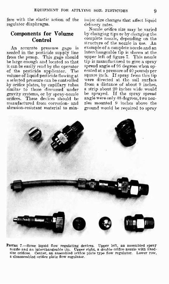
Nozzle orifice size may be varied by changing tips or by changing the complete nozzle, depending on the structure of the nozzle in use. An example of a complete nozzle and an interchangeable tip is shown at the upper left of figure 7. This nozzle tip is manufactured to give a spray spread angle of 95 degrees when op- erated at a pressure of 40 pounds per square inch. If spray from this tip were directed at the soil surface from a distance of about 9 inches, a strip about 20 inches wide would be sprayed. If the spray spread angle were only 48 degrees, two noz- zles mounted 9 inches above the ground would be required to spray
FiGTJEE 7.—Some liquid flow regulating devices. Upper left, an assembled spray nozzle and an interchangeable tip. Upper right, a double orifice nozzle with fixed- size orifices. Center, an assembled orifice plate type flow regulator. Lower row, a disassembled orifice plate flow regulator.

10 AGRICULTURE HANDBOOK NO. 297, U.S. DEPT. OF AGRICULTURE
a strip 20 inches wide. Thus, to cover a strip of given widtli, wide spray angles allow the use of fewer nozzles.
Fewer nozzles in turn allow the use of larger nozzle orifices and screens with larger openings for a particular application rate. This is desirable because suspensions of a wettable powder will pass through the large openings, and less clogging will occur than if small openings are used. Clogging can be further re- duced by the use of substantial amounts of water to dilute the sus- pensions. Total liquid application rates of 100 or 200 gallons per acre may be desirable for this purpose.
Another device frequently used to regulate the flow of soil pesticides is an orifice plate inserted in the liquid flow line (fig. 7). Orifice plates can be obtained in a wide range of sizes. Several sets in différent sizes should be obtained and calibrated for sev- eral application rates (51). With these available, the operator of the pesticide applicator will have a wide range from which to select an appli- cation rate.
A moderatei range in flow rates can be obtained by adjusting the op- erating pressure in the fluid line leading to the flow regulator. An initial calibration of the application rate should be made to be certain that operating conditions allow the flow regulators to deliver their rated capacities. Necessary adjustments can be made before treatment is started. This procedure prevents overdosage, which wastes pesticide and, in addition, may leave excessive chemical residue. Underdosage, which would very likely cause the treatment to fail, will also be pre- vented.
The rate of pesticide application can also be controlled by inserting coils of tubing of selected diameter and length in the liquid supply lines. Rate of flow at a .selected
pressure can be varied by changing either the diameter or the length of tubing in the coil. Needle valves may also be used to throttle flow and reduce volume.
Gravity flow rates in a system as simple as that shown in figure 2, A may be altered by changing the height of the supply tank. If a float valve and chamber are used to pro- duce a con.stant head, volume can be changed by reducing or increas- ing the height of liquid in the float chamber.
Manual applications of low vola- tile soil pesticides may be made by sprinkling a weighed or measured amount of the pesticide over a chosen area and mixing it into the soil with a rotary tiller or other tillage tool. The more volatile materials may be poured into open furrows and covered with soil or be injected through a metal tube thrust into the soil to the desired depth (5, 36, 4-1) ■ Devices for releasmg highly volatile fumigants are shown in figure 8.
Highly volatile fumigants may be released under a cover placed over a measured area (£9, p. 103-11^). The 1-pound containers of fumi- gant shown in figure 8 are placed in the clamp. Closing the clamp punc- tures the container and allows the fumigant, which is under pressure.
FIGURE 8.—Equipment for the controlled manual release of highly volatile soil fumigant.

EQUIPMENT FOR APPLYING SOIL PESTICIDES 11
to flow through the tube into a shal- low container under the cover (56'). The shallow container should be used to prevent adsorption of fumi- gant by the soil before vaporization can take place. The device shown at the right in figure 8 is useful for the application of small measured amounts of fumigant.
Terminal Distribution Devices
The distribution of pesticide into soil has been accomplished in a number of ways {12. 19, 31. 32, 0, ^7, IfS, Gif., 70). Some pesticide ap- plicators use parts of tillage imple- ments to obtain the desired place- ment of pesticide in the soil. A very simple method of distribution con- sists of spraying a pesticide on the soil and covering it with soil turned in by disks (fig. 9). Retention of pesticide in soil is improved by the
use of a drag that smooths and slightly compacts the soil surface. In irrigated areas, some soil pesti- cides can be applied by mixing them with the irrigation water (60).
Subsurface Dispersion Soil pesticides may be scattered
througli a soil mass by the use of disks, rotary hoe teeth, or rotary tiller blades (37). A pesticide ap- plicator using rotary hoe teeth has been effective where only a shallow dispersion below the soil surface is required.
An applicator using rotary tiller blades has been very effective for mixing pesticide into the soil in depth (27). Lange and Carlson (31) found that pesticides applied to a soil surface and rotary tilled once were dispersed to a depth of 5 inches as well as pesticides mixed into the soil by disking six times in two directions. A thorough dis-
FiGURE 9.—Soil pesticide applicator covering herbicide with soil turned in by disks. Pesticide is sprayed from nozzle located just ahead of the toolbar.

12 AGRICULTURE HANDBOOK NO. 297, U.S. DEPT. OF AGRICULTURE
riGUEE 10.—Soil pesticide applicator equipped with rotary tiller blades. Liquid pesticide is distributed across full width of the cut by spray nozzles.
persion of nonvolatile pesticides is required to reach soil-inhabiting pests at depths of 6 to 8 inches (35). A soil pesticide applicator equipped
FIGURE 11.—Pesticide applicator equipped with rotary tiller blades applying pes- ticide to a single-row width.
with rotary tiller blades does this satisfactorily (fig. 10). An appli- cator equipped with rotary blades can be used for applying pesticide in narrow rows as well as full width strips (fig. 11).
Subsurface Linear Application Soil pesticides may be applied
when the soil is plowed (13) to ob- tain a line or a sheet distribution of chemical at plowing depth. The initial spread of the liquid pesti- cide depends on whether it is to be applied to the bottom of the furrow as a narrow stream or is to be sprayed across the full width of the furrow.
An applicator commonly used for subsurface linear applications of soil pesticide consists of a frame on which spring-trip shanks are rig- idly mounted. A similar applicator

EQUIPMENT FOR APPLYING SOIL PESTICIDES 13
can be assembled by attaching spring shanks to a toolbar (fig. 12) and fitting the shanks with blades, points, or chisels. Tubing, prefer- ably of a flexible type, connects the supply system to the individual blades where the pesticide is dis- tributed into the soil.
Several shapes of fittings may be attached to the shanks to open a space in the soil where the pesticide can be deposited (28, 59). Points or chisels usually have good pene- tration qualities in hard soil but may leave a wide slot in the soil that allows volatile pesticide to escape without proper diffusion unless the slot is securely closed. Chisels, sim- ilar to those used on subsoiler im- plements, are desirable shank fit- tings for deep applications of soil pesticides.
Thin blades of the types shown in figure 6 leave only a narrow slit as they pass through the soil. Either the forward- or back-swept blade may be used. The forward- swept blade penetrates the soil more readily than a back-swept blade but collects roots and trash if these ma- terials are plentiful or have not thoroughly decayed. An accumu- lation of trash and roots on the blade may open a wide furrow through which volatile pesticides can escape before they become ef- fective. For best results, fumigants sliould be applied after plant roots and stems have completely decayed. If this condition does not prevail, the use of back-swept blades may be helpful.
The soil pesticide applicator shown in figure 12 injects the active
FIGURE 12.—Soil pesticide applicator with spring shanks mounted on a toolbar. Blades attached to shanks carry tubes from which pesticide is released at the desired depth below the soil surface.
14 AGRICULTURE HANDBOOK NO. 29 7, U.S. DEPT. OF AGRICULTURE
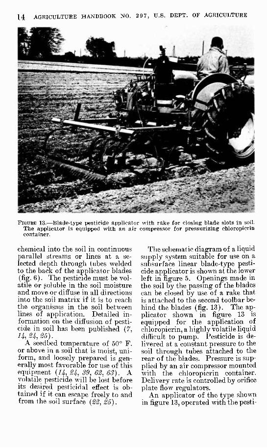
FIGURE 13.—Blade-type i)esticide applicator with rake for closing blade slots in soil. The applicator is equipped with an air compressor for pressurizing chloropicrin container.
chemical into the soil in continuous parallel streams or lines at a se- lected depth through tubes welded to the back of the applicator blades (fig. 6). The pesticide must be vol- atile or soluble in the soil moisture and move or diffuse in all directions into the soil matrix if it is to reach the organisms in the soil betAveen lines of application. Detailed in- formation on the diffusion of pesti- cide in soil has been published (7, 1Í •*, ?5).
A seedbed temperature of 50° F. or above in a soil that is moist, uni- form, and loosely prepared is gen- erally most favorable for use of this equipment (Z^, 21^, 39, 62, 63). A volatile pesticide will be lost before its desiretl pesticidal effect is ob- tained if it can escape freely to and from the soil surface {22, 25).
The schematic diagram of a liquid supply system suitable for use on a subsurface linear blade-type pesti- cide applicator is shown at the lower left in figure 5. Openings made in the soil by the passing of the blades can be closed by use of a rake that is attached to the second toolbar be- hind the blades (fig. 13). The ap- plicator shown in figure 13 is equipped for the application of chloropicrin, a highly volatile liquid difficult to pump. Pesticide is de- livered at a constant pressure to the soil through tubes attached to the rear of the blades. Pressure is sup- plied by an air compressor mounted with the chloropicrin container. Delivery rate is controlled by orifice plate flow regulators.
An applicator of the type shown in figure 13, operated with the pesti-

EQUIPMENT FOR APPLYING SOIL PESTICIDES 15
TABLE 1.—Yields of carrots ohtained from muck soil treated loith nematoclde hy stated methods for the control of root knot ^
Treatment Carrots
Method of distribution
Nematocide
Name 2 Amount per acre
Having root knot
Total yield
per acre
Market- able yield
per acre
Subsurface mixed _ Subsurface linear.. Subsurface mixed. Subsurface linear.. Subsurface mixed.
D-D® D-D® Ethylene dibromide.. Ethylene dibromide__ None
Gallons 45 45 36 36
Percent 4. 5
12.8 4.6 8.7
20. 0
Tons 29. 7 29.6 34. 6 31. 1 33.6
Tons 28. 4 25.8 33. 0 28.4 26.9
1 The muck soil was Rifle peat (0- to 3-percent slopes) in Huron County, Ohio. 2 See appendix.
cide flowing under pressure of 15 to 50 pounds per square inch, produces a more uniform and reliable appli- cation than if the pesticide were ap- plied under the low pressure pro- duced from a gravity head. ^^Hien highly volatile poisonous chemicals are applied by a pressure system, special care must be taken to assure that the system is free from leaks and is operated safely.
Results of Different Distribution Methods
The effects of two low-volatility nematocides applied as preplanting treatments by two methods of dis- tribut ion for controlling root knot in a muck soil (Rifle peat, Huron County, Ohio) in which vegetables were grown are shown in table 1. Under the conditions of this experi- ment, the subsurface-mixed treat- ment applied by an applicator equipped with rotary tiller blades (fig. 10) was more effective in re- ducing nematode-caused root knot than was the subsurface linear treat- ment applied by an applicator equipped with fixed blades and an attached rake (fig. 12). The greater yield of marketable carrots
782-909 O—66 3
reflects the reduction in nematode injury (table 1).
Results of preplant treatments in which soil pesticides of different volatility were applied by different methods are shown in table 2. In this experiment, the soil was treated to control verticillium wilt, a soil- borne disease of many vegetables (50, 62, 65), The less volatile fungicides that were subsurface mixed into the soil by rotary tilling provided less control of wilt and lower yields of vegetables than did the highly volatile chloropicrin applied to soil without mixing.
Fumigant Retaining Devices Permeable Fumigant Retainers
There are several w^ays to retard or prevent the escape of fumigants from the soil {22), Any practice that reduces surface porosity or eliminates ditches, furrows, grooves, or cracks can be expected to increase the effectiveness of volatile soil pesticides. Drags, rakes, or har- rows may be used to close or level furrows and cracks. Land rollers have a similar action and, in addi- tion, compact a layer of soil at the

16 AGRICULTURE HANDBOOK NO. 2 9 7, U.S. DEPT. OF AGRICULTURE
TABLE 2.—Effects of a preplantlng fungieidal soil treatment on the control of verticilUum wilt
Fungicide ' Eggplant Yield per acre 1
Name and method of distribution ^ Appli- cation
per acre Yield
Cull fruit
Toma- toes Potatoes
None . Gallons Pounds
107 287 265 384
Percent 5. 0 5. 9
15. 7 7. 1
Tons 18.0 20. 1 22.5 24.5
Bushels 280
Vapam (R) (subsurface mixed) Niagara 5961 (subsurface mixed) Chloropicrin (subsurface linear)
60 20 35
313 350 356
' Vapam and Niagara 5961 in water were applied to give the stated amounts of pesticide per acre when the solutions were mixed into the soil at a rate of 100 gallons per acre. Chloropicrin was applied without dilution as a linear subsurface injection using a fixed-blade applicator.
2 See appendix.
FiGUBE 14.—Applying a liquid seal over a single row subsurface-mixed soil pesticide application.
EQUIPMENT FOR APPLYING SOIL PESTICIDES 17
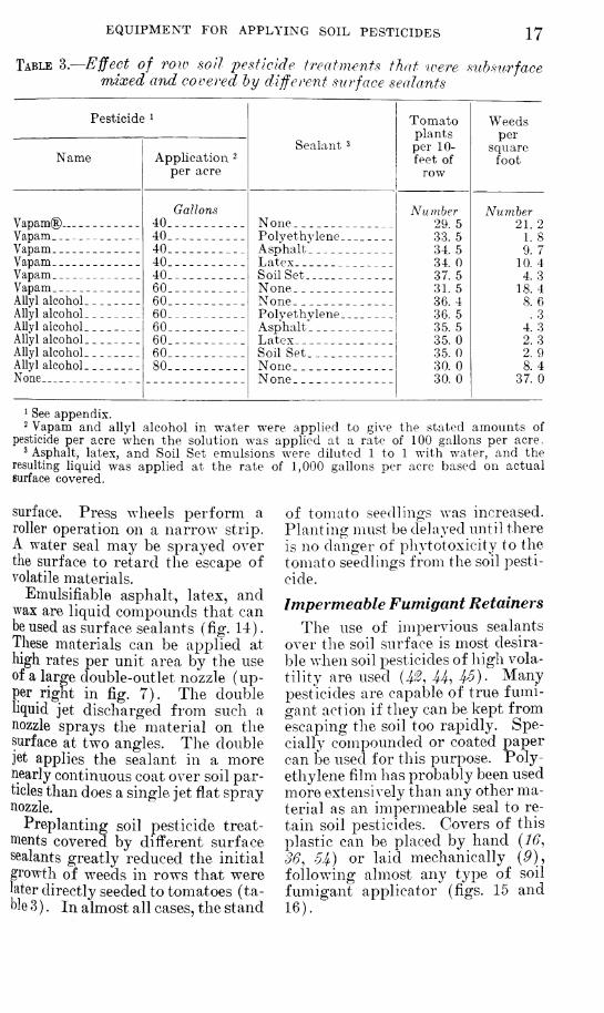
TABLE 3.- -Ejfect of TOW soil pesticide treatinents thit loere siihsurface mixed and covered hy different surface sealants
Pesticide i
Sealant 3
Tomato plants per 10- feet of
row
Weeds per
square foot Name Application ^
per acre
Vapam® _ Gallons
40 40 40 40 40
None Polyethylene Asphalt Latex Soil Set
Number 29. 5 33. 5 34. 5 34. 0 37. 5 31. 5 36. 4 36. 5 35. 5 35. 0 35. 0 30. 0 30. 0
Number 21 2
Vapam 1 S Vapam _ 9 7 Vapam Vapam.
10. 4 4 3
Vapam 60 60 60 60 60 60 80
None None Polyethylene Asphalt Latex
18 4 Allyl alcohol Allyl alcohol Allyl alcohol Allyl alcohol
8.6 .3
4. 3 2. 3
Allyl alcohol Soil Set _ _ _ __ 2. 9 Allyl alcohol None
None None
8.4 37. 0
^ See appendix. 2 Vapam and aUyl alcohol in water were applied to give the stated amounts of
pesticide per acre when the solution was applied at a rate of 100 gallons per acre. ^ Asphalt, latex, and Soil Set emulsions were diluted 1 to 1 with water, and the
resulting liquid was applied at the rate of 1,000 gallons per acre based on actual surface covered.
surface.. Press wheels perform a roller operation on a narrow strip. A water seal may be sprayed over the surface to retard the escape of volatile materials.
Emulsifiable asphalt, latex, and wax are liquid compounds that can be used as surface sealants (fig. 14). These materials can be applied at high rates per unit area by the use of a large double-outlet nozzle (up- per right in fig, 7). The double liquid jet discharged from such a nozzle sprays the material on the surface at two angles. The double jet applies the sealant in a more nearly continuous coat over soil par- ticles than does a single jet flat spray nozzle.
Preplanting soil pesticide treat- ments covered by different surface sealants greatly reduced the initial growth of weeds in rows that were later directly seeded to tomatoes (ta- ble 3 ). In almost all cases, the stand
of tomato seedlings was increased. Planting must be delayed until there is no danger of phytotoxicity to the tomato seedlings from the soil pesti- cide.
Impermeable Fumigant Retainers The use of impervious sealants
over the soil surface is most desira- ble when soil pesticides of high vola- tility are used {Jß, U, i^). Many pesticides are capable of true fumi- gant action if they can be kept from escaping the soil too rapidly. Spe- cially compounded or coated paper can be used for this purpose. Poly- ethylene film has probably been used more extensively than any other ma- terial as an impermeable seal to re- tain soil pesticides. Covers of this plastic can be placed by hand {16, 36, 5If) or laid mechanically (P), following almost any type of soil fumigant applicator (figs. 15 and 16).

18 AGRICULTURE HANDBOOK NO. 297, U.S. DEPT. OF AGRICULTURE
FiGUBE 15.—Attachment for laying polyethylene flbn over a subsurface linear application of soil pesticide.
FIGURE 16.—Attachment for laying polyethylene film over a subsurface mixed application of soil pesticide.

EQUIPMENT FOR APPLYING SOIL PESTICIDES 19 The cost of polyethylene film may
make its recovery desirable imder some circumstances (5, 10). The film is difficult to recover without tearing or puncturing and when re-
covered from silty soil is difficult to clean. Punctured and torn film must be repaired before it can be reused as a sealant for soil fumi- gation.
APPLICATOR COMPONENTS FOR GRANULAR-TYPE PESTICIDES
If the equipment has suitable com- ponents, the same general types of applicators used for liquid pesti- cides may be used for the applica- tion of granular pesticides.
Hoppers and Metering Devices
Hoppers on an applicator used for granular pesticides need not be so corrosion resistant as tanks used for liquid pesticides. Hoppers will
corrode se\'erely if not thoroughly cleaned or if wet granules are al- lowed to remain in them. It is im- portant that hojipers have sides that slope steeply toward the feed and metering mechanism in the hopper bottom. This design prevents bridging and facilitates the flow of granules into the metering device.
Several types of feeding devices suited to granular application are available (5.33). The accuracy of the rate of pesticide distribution
ir>i
FIGURE 17.—Granular soil pesticide applicator equipped with multiple hopper outlets and rot^ary tiller blades.

20 AGRICULTURE HANDBOOK NO. 297, U.S. DEPT. OF AGRICULTURE
depends on the performance of tlie feeding mecliani.sm. Feed rates should be carefully calilirated for each mechanism and each granular pesticide in order that feed settings be accurate. A metering device driven by a ground wheel can be expected to deliver an application that is proportionate to the forward travel of the implement.
Granular Dispersal Systems Granular pesticides metered from
the hopfwr in correct amounts must be uniformly applied on or through the soil in which their action is desired. They can be uniformly
distributed on the soil by using a hopper with multiple outlets, (fig. 17 appearing on page 19). Gran- ulas can be mixed into the soil by an applicator equipped with rotary tiller blades.
(îranules impregnated with vola- tile pesticides can be distributed in parallel subsurface lines by a blade- type soil pesticide applicator if large tub&s are used to conduct the granules from the hopper to their point of release in the soil {4S)- Devices for retaining fumigants in the soil are similar to those previ- ously described for use with liquid pesticides.
SPECIALIZED SOIL PESTICIDE APPLICATORS
Applicators for Treating the Root Zone of Living Plants A short toolbar to wliich is at-
tached a pair of rigid shanks or a pair of spring shanks with blades and covering devices can be used to apply nonphytotoxic soil pesticides to the root zone of living plants (fig. 18). This method of treating has proved useful in reducing nematode injury to certain plants (64). The blades on this equipment were mounted 12 inches apart to allow plants in the row to pass between them without injury to the growth above ground. Blade spacing must be close enough to assure the dif- fusion of injected soil pesticide in lethal concentrations throughout the root zone.
The use of very thin injector blades is suggested for treating liv- ing plants because even a smooth flat blade shows some tendency to lift plants and soil. This action may break and injure feeder roots of small, newly established trans- plants. Wide points or wings should be removed from blades when pesticides are applied in the
root zone of living plants. Openings left by the passing of
blades should be closed. Press wheels or drags may be attached to
FIGURE 18.—Pesticide applicator for placing a neinatocide as a side dressing in the root zone of nursery-grown roses.

EQUIPMENT FOR APPLYING SOIL PESTICIDES 21
''■ '"-■
1^ FiGDEE 19.—Blade-type two-row soil pesticide applicator equipped to seal slots left in
soil by the passing of blades. Press wheel equipment is on right ; drag equipment is on left.
the applicator for tliis purpose (fig. 19). Drags can be adjusted to give good closure in loose soil without depressing the surface directly over the fumigant injection.
Large colters make a very narrow cut when pulled through soil. They have been used on applicators that were placing pesticides in the root zone of growing vegetables (fig. 20). Colters miniminze the collec- tion of crop refuse, but, unless a shielding device is added, they will prune the plant growth that droops more than 6 inches to the side of the row.
Applicators for Treating the Seed Zone While Planting Some pesticides may be applied to
the soil near the seed when it is planted {50). A 4-row vegetable planter used in this method of soil treatment is shown in figure 21. Figure 22 shows the application of pesticide to the soil behind the fur- row opener but ahead of the press ^Yheel. The location of this appli- cation should be carefully adjusted because proper technique requires that some soil roll into the furrow and lightly cover the seed before the

22 AGRICULTURE HANDBOOK NO. 29 7, U.S. DEPT. OF AGRICULTURE
FiGUEB 20.—Soil pesticide applicator equipped with large colters for treating root zone of vegetable row. Press wheel sealing device on left ; drag sealing device on right.
pesticide is applied. The pesticide is then covered in the seed zone by the press wheel but is not in direct contact with the seed.
Results of applying pesticides in soil when onions were planted are given in table 4. The initial stand of onion seedlings in the untreated rows was better than that in some treated rows. Yields of onions, however, were best from the treated rows. The reduced yield in the un- treated rows resulted from damage to the plants by uncontrolled mag-
gots or smut. Treating the seed zone while planting has also pro- duced excellent seedling stands in several other vegetable plantings.
A pesticide applicator combined with a planter and other devices that are suitable for applying various types of pesticides and various combinations of treatments while used for seeding is shown in figure 23. Insecticide or fungicide or a mixture of these may be carried in a tank mounted on the left side of the tractor and sprayed into the

EQUIPMENT FOR APPLYING SOIL PESTICIDES 23
FioTJBE 21.—Four-row vegetable planter with pesticide application equipment placing pesticide in the seed furrow while planting onions.
seed row at selected rates in the manner described for equipment shown in figure 22.
In figure 23 two tanks pressur- ized by an air compressor are mounted over the right end of the toolbar. Each tank has a regulator that controls air pressure on the liquid in the tank. The rate of flow of liquid from the tanks to the point of release is controlled by adjusting these regulators. The larger of these two tanks contains a liquid sealing material; the smaller one (right), a herbicide. Each tank is provided with a re- movable inner container that allows changes from one pesticide or liquid seal to another to be made quickly. The use of throw-away polyethylene bags as liners in the container for the liquid sealants greatly simpli-
fies the cleanup process after use of sticky liquids. Any one pesticide, a combination of pesticides, or a combination of pesticides and seal- ant can be applied by opening or closing appropriate control valves.
Surface Incorporation Many kinds of tillage equip-
ment—including rotary hoes, disks, and weeders—may be used for plac- ing a soil pesticide at a shallow depth below the soil surface (5,37). Such treatments have been effective against some crop pests. These treatments, referred to as "incorpo- ration", have been particularly ef- fective in the application of numer- ous herbicides {2, h, 17, 3^, 38). In some cases, shallow mixing of fungicidal chemicals before crops

24 AGRICULTURE HANDBOOK NO. 29 7, U.S. DEPT. OF AGRICULTURE
FIGURE 22.—Spray nozzle used to apply soil pesticide in the seed furrow while planting.
FIGURE 23.—Equipment for planting vegetables and applying variable combinations of soil pesticides and liquid surface seals.

EQUIPMENT FOR APPLYING SOIL PESTICIDES 25
are planted, including vegetable and forest nursery plantings, has been inconclusive (67), Shallow appli- cations increase the concentration of chemical per unit volume of soil
if application rates per acre are kept constant. This has increased ef- fectiveness of certain herbicides applied by incorporation methods (S).
TABLE 4.—Results of some in-roio applications of fungicides and insecticides to an onion planting in muck soil^
Pesticide
Trade name 2 Application per acre
Manzate® (80%) VC-13 EC (7^2
pounds). Trithion® EC (2
pounds). Ethion (4 pounds) and
formaldehyde (40%). _
VC-13 and formal- dehyde (40%).
Cynem EC (4 pounds) and formaldehyde (40%).
VC-13 and Dithane D-14(20%).
VC-13 and Arasan 42-S.
No treatment.
6 pounds 0.133 gaUon
0.5 gallon
0.25 gallon and 2 gaUons, respec- tively.
0.133 gallon and 2 gallons, respec- tively.
0.25 gallon and 2 gallons, respec- tively.
0.133 gallon and 2 gallons, respec- tively.
0.133 gallon and 2 pounds, respec- tively.
Onions per foot
of row on May 22 Maggot-
infested
Number 23. 1 22. 6
20. 6
21. 1
23. 0
22. 6
24.3
20. 5
22.4
Plants per plot
Number 60
4
0
0
Smut- infected
Yield per acre in
50-pound
Number 0 4
6
3
12
Number 1, 133 1, 126
1, 129
1, 180
1,226
1,235
1,228
1, 123
960
1 Muck soil is Rifle peat (0- to 3-percent slopes) in Huron County, Ohio. 2 See appendix.
METHODS FOR CONTROLLING APPLICATION RATES OF SOIL PESTICIDES
Speed of Applicator One way of controlling the appli-
cation rate of pesticides is to regu- late the speed of the applicator. This method is accurate if the ap- plicator is equipped with a speed- ometer that indicates true forward travel with considerable precision. If the tachometer-type of instru- ment is used, the operator should assure himself that slippage and
compaction of the soil do not change the indicated ratios between engine speed and true forward travel. Ap- plicator speeds are readily varied by regulating the throttle, shifting gears, or by using both of these controls.
A considerable degree of control over the application rate may be accomplished by selecting the proper speed available through the tractor transmission. This method

26 AGRICULTURE HANDBOOK NO. 2 9 7, U.S. DEPT. OF AGRICULTURE
of control is well suited to linear subsurface treatments that are ap- plied by use of fixed blades or sim- ilar types of equipment. Changes in speed of this type applicator cause little change in the action of the tool or of any attached rake or drag.
Changing the forward speed of an applicator that makes a subsurface dispersion of pesticide through the mixing action of rotary tiller blades may not prove satisfactory unless the speed of the rotating blades is changed to maintain a constant length of cut. If this is not done, the mixing action may be increased or decreased depending on the ratio maintained between forward travel and speed of rotation of the tiller blades.
Flow Rate of Fluid Pesticides
The application rate of fluid soil pesticides can also be changed by altering the rate of flow to release points. This is readily accom- plished by selecting the proper op- erating pressure for use with the chosen nozzle or orifice plate. The operation of these devices has been previously discussed.
Calculations for Applying Fluids Rates of pesticide application are
recommended in various ways, usually by the number of pounds or gallons to be distributed per acre or by the amount to apply per foot of row. Specialized information or charts of conversion factors and methods for the calculation of application rates are available (16; 16; 18; 29, p, 103-112; 39; 48; 60; 61). A few of the simple con- version factors that are often useful in calculating application rates are :
1 mile=5,280 feet. 1 mile per hour =88 feet per
minute.
1 acre=43,560 square feet. 1/4 acre= 10,890 square feet=area
15 feet x 726 feet. 1/100 acre=4r35.6 square feet=
area approximately 15 feet x 29 feet or 17.4 feet x 25 feet.
100 feet of 2-foot (24-inch) row = 0.0046 acre or approximately 0.005 acre.
1 gallon = 128 ounces =3,785.4 milliliters.
1 pint=16 ounces=473.2 milli- liters.
1 fluid ounce=29.6 milliliters= 480 drops or minims.
1 pound=16 ounces=453.6 grams.
Many methods are available for calculating the application rates of liquids. The following formulas may be helpful to operators in making such calculations. If:
TF=Treated width in feet, /§"=Speed of travel in miles per
hour, and Ä = Gallons of liquid to be
applied per acre.
Then:
495" -- 0.002 SW=acres treated
per minute, or approxi-
mately -^.
and:
'^J^/^-0.002 /SFÄ=gallons of
liquid applied per min- ute, or approximately SWR
500 '
If treated widths are narrow and are measured in inches, then Wi = treated width in inches, and
^^^=0.00017 SW,R=g2i\\ons of 5940
liquid applied per minute. The decimal or fraction can be rounded off to the desired approximation.

EQUIPMENT FOR APPLYING SOIL PEfSTICIDES 27 Gallons of liquid applied per
minute can be converted to any de- sired unit of measurement if multi- plied by an appropriate conversion factor. For example, the formula
-^^multiplied by 3785.43 = the
required application rate in milli- liters per minute ; thus :
SW,R (3785.43)_^TF,/g 5940 1.569
= 0.637 SW^R milliliters per min- ute.
Liquid flow rates per minute that are required to give stated applica- tions in gallons per acre over a stated specific width of treatment are shown in tables 5 and 6.
Flow rates given in tables 5 and 6 apply only to the stated width at
the stated application rate per acre for the travel speeds shown. Appli- cation rates per acre based on row spacings that may vary from 12 inches to 12 feet with a correspond- ing multitude of variations in lui- treated widths between the rows thejiiselves are beyond the scope of tables 5 and 6.
Flow rates required to treat widths not shown in tables 5 and 6 can be obtained by simple multi- plication. For example, table 6 gives flow rates for a treated strip 1 foot wide. The flow rate for 60 gallons per acre at 2 miles per hour is 1.92 pints per minute. If we wish to treat a strip 8 feet wide, the total flow rate required would be 15.36 pints per minute (8 X 1.92). If the pesticide is distributed across the 8-
TABLE 5.—Flow rates and travel speeds required to obtain stated applica- tion rates of pesticide on a strip of soil 10 inches \oide ^ ^
Application rate per— Flow rate per minute required when—
Acre 1001
Gallons Pints 200 3.06 175 2.68 150 2.30 125 1.91 100 1.53 75 1. 15 60 .92 50 .76 40 .61 35 .54 30 .46 25 .38 20 .31
Applicator travel speed is lyi miles per hour
Milliliters 1,448. 4 1, 267. 4 1, 086. 3
905.3 724. 2 543. 2 434. 5 362. 1 289.7 253. 5 217. 3 181. 1 144. 8
Pints Ounces 4.04 64.7 3.54 56.6 3. 03 48.5 2. 53 40.4 2. 02 32.3 1.52 24. 2 1.21 19. 4 1.01 16. 2
. 81 12.9
. 71 11.3
.61 9.7
. 51 8. 1
.40 6. 5
Milliliters 1,911. 6 1, 672. 6 1, 433. 7 1, 194. 8
955. 8 716. 8 573. 5 477.9 382.3 334. 5 286. 7 239. 0 191.2
Applicator travel speed is 2 miles per hour
Pints 5. 39 4. 71 4. 04 3. 38 2.69 2. 02 1. 62 1.35 1. 08 .94 .81 .67 . 54
Ounces 86. 2 75.4 64. 6 53.9 43. 1 32. 3 25.9 21. 6 17. 2 15. 1 12.9 10.8
8. 6
Milliliters 2, 548. 8 2, 230. 2 1,911. 6 1, 593. 0 1, 274. 4
955.8 764.6 637.2 509.8 446. 0 382.3 318. 6 254. 9
^ To calculate flow rates for treating a 10-inch width of soil at application rates and travel speeds not shown in the table: Let Ä=application rate per acre in gallons and o=travel speed in miles per hour. Required flow rate per minute in milliliters is
6.372 SR; in ounces, 0.2155 SR; and in pints, -|^= 0.0135 SR,
^ To convert application rate in gallons-per-acre on a 10-inch width to an equal
linear application rate: Pints per 100 feet = ^^^^ = Q.01530 R; milliliters per 100
''''=ôm='-'''' ^• 65.34

28 AGRICULTURE HANDBOOK NO. 2 9 7, U.S. DEPT. OF AGRICULTURE
TABLE 6.—Floto rates and travel speeds required to obtain stated applica- tion rates of pesticide on a strip of soil 12 inches wide ^ ^
Application rate per— Flow rate per minute required when —
Acre 100 linear feet Applicator travel speed is Applicator travel speed is ] y2 miles per hour 2 miles per hour
Gallons Pints Milliliiers Pints Ounces Milliliters Pints Ounces Milliliters 200 3.67 1,738. 0 4. 85 77. 6 2, 293. 8 6.46 103.4 3, 058. 4 175 3. 21 1, 520. 8 4. 24 67. 9 2, 007. 1 5. 66 90.5 2, 676. 1 150 2.75 1,303. 5 3.63 58. 2 1,720. 3 4. 85 77.6 2, 293. 8 125 2.29 1, 086. 2 3.03 48. 5 1,433. 6 4. 04 64.6 1, 979. 1 100 1.83 869.0 2.42 38. 8 1, 146. 9 3. 23 51.7 1, 529. 2 75 1.38 651.7 1.82 29. 1 860. 2 2.42 38.8 1, 146. 9 60 1. 10 521. 4 1. 46 23. 3 688. 1 1. 92 3L0 917.5 50 . 92 434. 5 1.21 19. 4 573. 4 1.62 25.8 764.6 40 . 74 347.6 . 97 15. 5 458. 8 1. 30 20. 7 611.7 35 . 55 260.7 .73 11. 6 344. 1 .97 15.5 458.8 25 .46 217. 2 .61 9.7 286.7 .81 12. 9 382.3 20 .37 173.8 .49 7.7 229.4 .65 10.3 305.8
^ To calculate flow rates for treating a 12-inch width of soil at application rates and travel speeds not shown in the table: Let Ä = application rate per acre in gallons and <S=travel speed in miles per hour. Required flow rate per minute in milliliters is
7.646 SR; in ounces, 0.2585 SR; and in pints, ^3^^= 0.01616 SR. 01.875
2 To convert application rate in gallons-per-acre on a 12-inch width to an equal
linear application rate: Pints per 100 feet = —^=0.01836 R: milliliters per 100 54.45
^^et=-^^=8.690 R.
foot width from 4 outlets, the flow should be divided equally between them if they are spaced at equal in- tervals across the width. Thus, in this example, each outlet should dis- charge 3.84 pints per minute.
Rates of flow for other speeds can also be readily calculated from ta- bles 5 and 6. Suppose it is desired to apply 100 gallons of pesticide per acre to a 10-inch width of soil at 3 miles per hour. Reference to table 5 shows that a flow rate of 2.02 pints per minute is required to apply 100 gallons per acre to a 10-inch width of soil at a travel speed of n/y miles per hour. At 8 miles per hour, the total flow rate must be doubled to 4.04 pints per minute (2 X 2.02). If the pesticide is distributed through more than one outlet, the total flow rate must be divided by the number
of outlets to determine the amount of pesticide that should be dis- charged by each individual outlet. This assimies the outlets are equally spaced across the width of the pesti- cide applicator.
If it is desired to apply pesticide to a 10-inch treatment width at 100 gallons per acre and the applicator travels 31/2 miles per hour, the re- quired flow rate can be obtained by adding the rates stated in table 5 for IV2 and 2 miles per hour (2.02 + 2.69 ). Other combinations or trans- formations will suggest themselves as the need arises.
Flow rates should be verified for each pesticide applicator by cali- bration. This can be done by oper- ating the equipment, with pesticide flowing under the pressure and other conditions selected for the ap-

EQUIPMENT FOR APPLYING SOIL PESTICIDES 29
plication. The volume of liquid flowing from an injector tube or a spray nozzle for a chosen length of time should be collected and meas- ured. These measurements are then converted to flow rates per minute. Operating adjustments are made as needed to obtain the desired flow rates.
Measurements of low flow rates made during a short time interval should be timed with a stopwatch or a watch with an accurately readable sweep second hand. If this type of timing equipment is not available, flow should be measured over a longer time interval to decrease the effect of small errors in timing the flow.
Two blades on an applicator that is used for sidedressing both sides of a row of plants with pesticide double the width of soil treated. For example, if the blades have one outlet each and are spaced 12 inches apart (fig. 20), the total soil width treated is 24 inches because the f umigant action takes place on both sides of each blade.
Soil pesticide application rates are sometimes stated in amounts of material applied per 100 linear feet of row. Examples of such rates are shown in columns 2 and 3 of tables 5 and 6. Referring to the first line in the second column of table 5 and reading across the page on that line, the table shows that 3.06 pints of pesticide would be applied per 100 feet of row if the applicator traveled li^ miles per hour and pesticide flowed at the rate of 4.04 pints per minute (1,911.6 milliliters per minute). For applying exactly 3 pints of pesticide per 100 feet, the flow rate per minute w^ould have to be reduced by 28 milliliters; or about 0.06 of a pint. A measure reading in ounces or milliliters should be used to obtain this degree of precision in adjusting the flow' rate.
Increasing the flow rate in the preceding example by 28 milliliters would increase the application rate 3.7 gallons per acre. Although the error is only 1.8 percent in an ap- plication rate of 200 gallons per acre, the error becomes increasingly important as application rates per acre are lowered. Therefore, to in- crease the accuracy of the calibra- tions, smaller measurement units should be used when calibrating equipment for low pesticide appli- cation rates.
In the section "Components for Volume Control,'' it was stated that clogging decreases when pesticide suspensions are copiously diluted and applied at a high rate of liquid per acre. Care must be taken to assure that the correct amount of active pesticide is used even though it is diluted. If the pesticide for- mulation is a 25-percent (by vol- ume) emulsifiable compound and it is desired to distribute 4 gallons of active pesticide per acre, then 16 gallons of the emulsifia;ble formula- tion must be applied per acre (16X0.25=4). If 100 gallons of liquid per acre is selected as the amount to be introduced into the soil by the applicator, the 16 gal- lons of emulsifiable formulation should be mixed with 84 gallons of water to make up 100 gallons for the total application. This mixture can then be applied according to the rates stated in tables 5 or 6.
Pesticides formulated at other percentages of concentration than the 25 percent explained in the fore- going example or that contain a specified weight of pesticide per gallon require similar calculations to determine correct amounts to use for any selected application rate. If application rates are stated in pounds of pesticide to be applied per acre, the container label should indicate the percentage by weight or the actual weight of active pesti-

30 AGRICULTURE HANDBOOK NO. 29 7, U.S. DEPT. OF AGRICULTURE
gallon of the cicle contained in a formulation.
As an example of such a calcula- tion, assume 10 pounds of a pesti- cide is to be applied per acre and that the label on the pesticide con- tainer states the formulation weighs 12.2 pounds per gallon and contains 70.7 percent of the pesticide by weight. The amount of pesticide in a gallon of formulation is, there- fore, 8.6 pounds (12.2 X 0.707). The quantity of formulation required to obtain 10 pounds of pesticide is 1.16 gallons (10^8.6). To make an ap- plication of 60 gallons per acre that contains the 10-pound dose of pesti- cide, mix 1.16 gallons of the formu- lation with 58.84 gallons of wat^r. The 60 gallons should be applied at the flow rate in table 5 to treat a 10- inch strip or the flow rate in table 6 to treat a 12-inch strip.
The use of wide-angle spray nozzles to distribute pesticide across the treated swath when making a subsurface dispersion type of ap- plication has been mentioned. The width of spread of the spray pat- tern formed by a nozzle may be varied by changing the operating pressure. The spread angle also varies between difl'erent types and sizes of nozzles operated at a single pressure. Many manufacturers of spray nozzles can supply informa- tion showing spray-pattern spread angles and corresponding pressure characteristics for their products.
Soil pesticide that is distributed by a spray nozzle may be spread across too wide a swath or the spread may be too narrow if the nozzle is improperly located on the pesticide applicator. Spray nozzles may be mounted vertically or their
TABLE 7.—Distance (D) from nozzle orifice required to obtain spray pattern of stated width (TT)^
Width of spray
Distance when spray-spread angle (A) ^ of nozzle is—
pattern (W) 15^ 25° 30° 40° 50° 65° 73° 80° 95° 110°
Inches 1
Inches 3.80 7.60
11.39 15. 19 18. 99 22. 79 30.38 37.98 45.58 53. 17
Inches 2.25 4.51 6.77 9. 02
11.28 13.53 18.04 22.55 27. 07 31.58 36. 09 40. 60 45. 11 49.62
Inches 1.87 3.73 5.60 7.46 9.33
11.20 14.93 18.66 22. 39 26. 12 29.86 33. 59 37. 32 41. 05 44. 78 48. 52
Inches 1.37 2. 75 4. 12 5.49 6. 87 8.24
10.99 13.73 16.48 19. 23 21.98 24. 72 27.47 30. 22 32.96 35.71 38.46 41.20
Inches 1. 07 2. 14 3.22 4.29 5.36 6.43 8.58
10. 72 12.86 15. 01 17. 15 19.30 21. 44 23.58 25.73 27. 87 30. 02 32. 16
Inches 0.78 1.57 2.35 3. 14 3.92 4. 71 6.28 7.85 9.42
10.99 23.56 14. 13 15.70 17.27 18.84 20.41 21.98 23.55
Inches 0.69 1.38 2.06 2.75 3.44 4. 13 5. 50 6.88 8.26 9.63
11. 01 12.38 13. 76 15. 14 16.51 17.89 19.26 20.64
Inches 0.60 1. 19 1.79 2.38 2,98 3,58 4.77 5.96 7. 15 7.34 9.54
10. 73 11.92 13. 11 14.30 15.50 16. 69 17. 88
Inches 0.46 0.92 1.37 1.83 2.29 2.75 3.66 4.58 5.50 6.41 7.33 8.24 9. 16
10.08 10.99 11.91 12.82 13. 74
Inches 0 35
2 0 70 3 1 05 4 5
1.40 1 75
6____ 2. 10 2.80 3.50 4.20 4.90 5.60 6.30 7.00 7.70 8.40 9. 10 9.80
10.50
8 10 12 14 16 18 20 22 24 26 28 30
1 Formula for computing distance (D) in inches from spray nozzle orifice to a desired
width of spread in the spray pattern: D = ^X cotangent -.

EQUIPMENT FOR APPLYING SOIL PESTICIDES 31 axis may be inclined to the direction of travel. They should be placed so that the distance from the nozzle orifice to the center of spray impact on the soil, allows the spray to spread and cover the desired width. This distance (table 7) should be measured along the central axis of the projected spray. For example, if it were desired to distribute a soil pesticide across a width of 60 inches using only three vertically mounted nozzles, each nozzle should dis- tribute pesticide across 20 inches (60-Í-3). A spray nozzle having a spread angle of 110 degrees does this if the nozzle orifice is 7 inches above the soil surface where the spray is incorporated into the soil by the mixing action of the applica- tor's blades (table 7).
A pesticide spray entering the seed row as shown in figure 22 should be narrow enough to enter the gap left by the furrow opener. If this gap is about 1 inch wide, reference to table 7 shows that a vertically mounted nozzle produc- ing a 25-degree spray angle should be mounted 2.25 inches above the furrow opening for such an appli- cation. A spray pattern of greater angular spread would require that the nozzle be mounted closer to the furrow opening.
Flow Rate of Granular Pesticides
Granular soil pesticides should be applied as carefully as liquid pesti- cides. Much of the discussion re- garding control of travel speed and flow rates applies also to granular pesticides.
Ground-driven feed mex^hanisms should be calibrated at several speeds to assure that the application rate for the particular granular ma- terial being applied is correct for the rate of travel being used. If the hopper has multiple feed out-
lets, the delivery from each should be measured to be certain they are equal. If granular flow is divided in the distribution tubes, flow meas- urements should be taken to prove the divisions are receiving equal quantities of granules.
Calculations for Applying Granules
Application rates for granular soil pesticides are usually stated in pounds per acre. Many manufac- turers of equipment and some pro- ducers of granular pesticides can provide tables showing proper set- tings of the feed mechanism for se- lected flow rates of specified gran- ular pesticides.
Table 8 can be used to calibrate an applicator by collecting and weighing the granules that flow from the delivery tubes when the applicator moves at selected for- ward speeds with chosen feed set- tings. Weights per minute shown in table 8 are totals for the stated soil treatment width and speed of applicator travel. If the pesticide applicator has equally spaced mul- tiple outlets, the total must be di- vided by the number of outlets to obtain the weight of granules to be delivered through any individual outlet. If the width of the appli- cation is to be only 20 inches, the total weight of granules per min- ute shown in table 8 for a stated application rate must be divided by 3. If the treated width is 60 inches and the applicator travels at 3 miles per hour, the weight of granules per minute shown in the table must be multiplied by 1.5 to obtain the flow rate required to provide the stated application rate per acre.
Soil pesticide applications are sometimes recommended by stating the pounds of pesticide to be ap- plied per acre rather than the weight of granules per acre. In this ca^e, additional calculations are needed

32 AGRICULTURE HANDBOOK NO. 2 9 7, U.S. DEPT. OF AGRICULTURE
to obtain the proper application rates. For example, if 50 pounds of pesticide is needed per acre and
TABLE 8.—Weights of granules re- quired to treat a strip of soil 60 inches %oide at stated application rates when applicator travels 2 miles per hour
Applica- tion rate per acre (pounds)
500 450 400 350 300 250 200 150 100 75_. 60_. 50_. 40_. 30_. 25_- 20_. 15_. 10-. 5__.
Weight of granules per minute
Pounds 10. 10
9. 09 8. 08 7. 07 6. 06 5. 05 4. 04 3. 03 2. 02 1. 51 1.21 1. 01
. 81
. 61
. 50
.40
.30
. 20
. 10
Ounces 161. 6 145. 4 129. 3 113. 1 97. 0 80. 8 64. 6 48. 5 32.3 24, 2 19.4 16. 2 12. 9
9. 7 8. 1 6.5 4. 8 3.2 1. 6
Grams 4, 582. 6 4, 124. 0 3, 665. 8 3, 207. 6 2, 749. 3 2, 291. 1 1, 832. 9 1, 374. 7
916. 4 687, 3 549. 9 458.2 366. 6 274. 9 229. 1 183. 3 137. 5 91. 6 45. 8
the container label states that the granular formulation contains 34.6 percent of the pesticide, then each pound of granules contains 0.346 pound of the pesticide. Therefore, to obtain an application of 50 pounds of pesticide per acre, 144.5 pounds of granules must be ap- plied (50-^0.346=144.5).
If the amount of pesticide to be applied were specified in gallons in- stead of in pounds, the operator would need to know the weight per gallon of the pesticide to calculate the required granular formulation application rate. Suppose a grower wishes to apply 5 gallons of nema- tocide per acre to his soil. The con- tainer label states that the nemato- cide weighs 17.3 pounds per gallon. The weight to be applied is 86.5 pounds per acre (5X17.3 = 86.5). Calculations remaining are the same as in the preceding paragraph ex- cept in this case a greater amount of pesticide is to be applied per acre. If the granular formulation to be applied contains 34.6 percent by weight of the nematocide, 250 pounds of granules must be applied per acre (86.5-^0.346=250).
CLEANING APPLICATOR EQUIPMENT Applicator equipment should be
thoroughly cleaned and flusl^ed after it has been used. The main purpose of this cleaning is to re- move as much corrosive chemical residue as possible. A petroleum solvent should be used to wash away compounds containing halogenated hydrocarbons. Water should not be used because it may react with these compounds to produce hydro- chloric acid, which is highly corro- sive to iron, magnesium, and aluminum and to alloys of these metals. Under these circumstances, the final cleaning and ñushing of the applicator should be done with
Stoddard solvent or with other petroleum solvents sold under vari- ous trade names.
If distillate or kerosene is used for cleaning an applicator, it should be mixed with some lubricating oil to reduce the volatility. Kerosene or distillate used without the addi- tion of oil will remove the natural oils from leather seals or gaskets and greatly reduce their useful life. Gasoline should never be used for cleaning or flushing because it is highly explosive and very danger- ous to use for such purposes.
Aft^r the pump, pipelines, and other parts of a liquid pesticide ap-
EQUIPMENT FOR APPLYING SOIL PEiSTICIDES 33
plicator have been thoroughly cleaned by the use of the proper cleaning material, they may be left filled with the cleaner. This will exclude air and greatly reduce the amount of corrosive oxidation dur- ing short idle periods. As previ- ously mentioned, never allow water to stand in an applicator that has been used for applying any of the halogenated hydrocarbons.
Parts that have been exposed to pesticide should be cleaned and given a light coating of petroleum solvent or other rust inhibitor if the applicator is to be out of service for a long period.
Granular applicators should be thoroughly washed and dried after they have been used. The hopper, feed mec'hanism, and conductor tubes should be free from chemical dust after cleaning. Chemical dust may combine with condensed mois- ture to form corrosive compounds that are harmful to applicator parts. After cleaning and drying, compK)nents should be given a light coat of oil or rust inhibitor to pre- vent corrosion. Before using the applicator again, this material must be completely removed from all parts that come in contact with pesticide granules.
SELECTED REFERENCES
(1) AMERICAN SOCIETY FOR TESTING AND MATERIALS.
1964. STANDARD SPECIFICATIONS FOR SIEVES FOR TESTING PUR- POSES. Amer. Soc. Testing Mater. E 11-61, ASTM Standards Part 30: 161- 168,
(2) ANONYMOUS.
1964. SOIL INCORPORATION. Farm Mach. World 3(3) : 5-16.
(3) AsHTON, F. M., and DUNSTER, K.
1961. THE HERBICIDAL EFFECT OF EPTC, cDEc, and CDAA ECHI-
NOCHOLA CRUSGALLI WITH VARIOUS DEPTHS OF SOIL IN- CORPORATION. Weeds 9(2) : 312-317.
(4) BECKER, C, and COSTEL, G.
1962. EFFECTS OF INCORPORATION METHODS ON HERBICIDE WEED CONTROL IN SUGAR BEETS. Through the Leaves 50(1) : 28^-31.
(5) COSTEL, G. L., HOOD, G., and ALLEY, H. P.
1960. EQUIPMENT FOR METERING,
DISTRIBUTING, AND MIXING
GRANULAR HERBICIDES IN
BANDS. Amer. Soc. Agx. Engin. Trans. 3(2): 108- 110, nius.
(6) BLACK, D. T.
1956. EFFEX7T OF PESTICIDES ON AP- PLICATION EQUIPMENT. U.S. Dept. Agr., Agr. Res. Serv., Agr. Engin. Research Div., Progress report to pesticide
and application equipment committee, No. 5 : 3-4.
(7) BRAZEE, R. D., and HEDDEN, O. K.
1963. SOME THEORETICAL ASPECTS OF SOIL FUMIGANT DIFFU- SION U.S. Dept. Agr., ARS 42-80, 15 pp., illns.
(8) CHRISTIE, J, R., and TAYLOR, A. L. 1960. CONTROLLING NEMATODES IN
THE HOME GARDEN. U.S. Dept, Agr., Farmers Bui. 2048, rev., 10 pp., illus.
(9) CLIFFORD, E. C. 1959. A RAPID METHOD OF FUMI-
GATING NURSERY SOILS WITH METHYL BROMIDE. U.S. Dept. Agr., Forest Serv. Tree Planters Notes No. 37, pp. 9-10, illus.
(10) — and HOWE, R. G. 1963. RECLAIMING POLYFILM TARP
FOLLOWING SOIL FUMIGATION OF SEEDBEDS. Down tO Earth 19(2) : 11-12.
(11) CROSSAN, D. F., BIEN, W. L., MORE-
HART, A. L., and BANIECKI, J. F. 1963. CONTROL OF RHIZOCTONIA
ROOT-ROT OF SNAP BEAN : LOW VOLUME IN-THE-FUR- ROW VERSUS HIGH VOLUME PREPLANT FUNGICIDAL SPRAYS. U.S. Dept Agr., Agr. Res. Serv., Plant Dis. Rptr. 47(2) : 109-111.
(12) CYKLER, J. F., and TRLBBLE, R. T.
1961. PRINCIPLES OF INJECTION SOIL FUMIGATION. Amer. Soc. Agr. Engin. Trans. 4(2) : 199-202, illus.

34 AGRICULTURE HANDBOOK NO. 2 9 7, U.S. DEPT. OF AGRICULTURE
(13) DALLIMORE, C. E. 1960. SOIL FUMIGATION WITH A
TWO-BOTTOM TWO-WAY PLOW. Idaho Agv. Expt. Sta. Bui. 337, 20 pp., illus.
(14) DIETER, C. E. 1954. FACTORS AFFECTING RESULTS
WITH SOIL FUMIGANTS. U.'S. Dept. Agr., Agr. Res. Serv., Plant Dis. Rptr. Supp. 227, pp. 98-101.
(15) Dow Chemical Company. 1958. SOIL FUMIGATION HANDBOOK.
36 pp., illus. Midland, Mich.
(16) 1962. CALIBRATION AND EQUIPMENT
FOR APPLYING TRIZONE FROM PRESSURE CYLINDERS. Tech. Bul. No. 125, 19 pp., illus. Midland, Mich.
(17) ENO, C. F.
1958. WHAT PESTICIDES DO TO
SOILS, 2. INSECTICIDES AND THE SOIL. AgT, and Food Chem. 6(5) : 348-351.
(18) Entomological Society of America. 1961-1962. TABLES OF INFORMA-
TION, ENTOMA. 14th ed., 166-177, Madison, Wis.
(19) FENSTER, C. R., HANWAY, D. G., and BURNSIDE, O. D.
1962. EQUIPMENT FOR SUBSURFACE APPLICATION OF HERBICIDES IN FALLOW LAND. WeedS 10(4) : 329-330.
(20) FREAR, D. E. H. 1964. PESTICIDE HANDBOOK. CK)!.
Sei. Pub., state College, Pa.
(21) FULTON, R. A., SMITH, F. F., and BUSBEY, R. L.
1964. RESPIRATORY DE\T:CES FOR
PROTECTION AGAINST CERTAIN PESTICIDES. U.S. Dept Agr., ARS 33-76-1, 12 pp., illus.
(22) GOOD, J. M.
1964. EFFECT OF SOIL APPLICATION AND SEALING METHODS ON THE EFFICACY OF ROW AP- PLICATIONS OF SEVERAL SOIL NEMATOCIDES FOR CONTROL- LING ROOT-KNOT NEMATODES, WEEDS, AND FUSARIUM WILT. U.S. Dept. Agr., Agr. Res. Serv., Plant Dis. Rptr. 48(3) : 199-203, illus.
(23) and RANKIN, H. W. 1964. EVALUATION OF SOIL FUMI-
GANTS FOR CONTROL OF NEMA- TODES, WEEDS, AND SOIL FUNGI. U.S. Dept. Agr., Agr. Res. Serv., Plant Dis. Rptr. 48(3) : 194-199.
(24) GORING, CLEVE A. I. 1957. FACTORS INFLUENCING DIF-
FUSION AND NEMATOCIDE CONTROL BY SOIL FUMIGANTS. Dow Chemical Co., ACD Inform. Bui. 110, 53 pp., illus. Midland, Mich.
(25) HEM WALL, J. B. 1960. THEORETICAL CONSIDER A-
TIONS OF SEVERAL FACTORS INFLUENCING THE EFFECTIV- ITY OF SOIL FUMIGANTS UNDER FIELD CONDITIONS. Soil Sei. 90(3) : 157-168.
(26) HOLDS WORTH, R. P., JR. 1964. HOW TO USE CROP SPRAYS
SAFELY. Ohio Agr. Ext. Serv., Columbus, Ohio.
(27) HuLBERT, W. C, and MENZEL, R. G. 1953. SOIL MIXING CHARACTERIS-
TICS OF TILLAGE IMPLEMENTS. Agr. Engin. 34(10) : 702- 708.
(28) JENSEN, H. J., HOPPER, W. E. R.,
and PAGE, G. E. 1964. CONTROL OF STUBBY ROOT
NEMATODE IN OREGON PLANT- INGS BY SOIL FUMIGATION. U.S. Dept. Agr., Agr. Res. Serv., Plant Dis. Rptr. 48(3) : 225-227.
(29) KNOTT, J. E. 1962. HANDBOOK FOR VEGETABLE
GROWERS. 238 pp. J. Wiley & Sons, Inc. New York, N.Y.
(30) KRAUSCHE, KENNETH. 1959. GRANULAR PESTICIDES. Agr.
Chem. 14(4) : 31-32, 129. (31) LANGE, W. H., JR., and CARLSON.
E. C. 1955. ZONAL DISPERSION OF CHEM-
ICALS IN SOIL FOLLOWING SEVERAL TILLAGE METHODS. Jour. Econ. Ent 48(1) : 61- 67.
(32) LEAR, B., MAE, W. F., FELDMESSER,
J., and SPRUYT. F. J. 1952. SOIL FUMIGATION EXPERI-
MENTS ON LONG ISLAND, NEW YORK, TO CONTROL GOLDEN NEMATODE OF POTATOES. Phytopathology 42(4) : 193- 196.
(33) LOVELY, W. G., COX, H. C, and BRINDLEY, T. A.
1956. APPLICATION EQUIPMENT FOR GRANULATED INSECTICIDES. Jour. Econ. Ent. 49(6) : 839-846, illus.
(34) MARTIN, J. P., and PRATT, P, F.
1958. WHAT PESTICIDES DO TO SOILS, 1. FUMIGANTS, FUNGI- CIDES, AND THE SOIL. Agr.

EQUIPMENT FOR APPLYING SOIL PESTICIDES 35 and Food Chem. 6(5) : 345- 348
(35) MCBETH, C. W., WHITE, L, V, and ICHIKAWA, S. T.
1964. A NEW RESIDUAL NEMATO- CIDE: 2,4-DICHLOROPHENYL
METHANESULFONATE. U.S. Dept. Agr., Agr. Res. Serv., Plant Dis Rptr. 48(8) : 634-635.
(36) MoNY, C. C. 1959. MANUAL APPLICATION OF
METHYL BROMIDE SOIL FUMI- GANT. U.S. Dept Agr., For- est Serv., Tree Planters Notes No. 37, pp. 7-8.
(37) NEWHALL, A. G., and GUNKEL, W. W. 1959. EFFICIENT INCORPORATION OF
GRANULAR FUNGICIDES AND OTHER CHEMICALS IN THE ROOT ZONE OF CULTIVATED SOILS. U.S. Dept. Agr., Agr. Res. Serv., Plant Dis. Rptr. 43(1) : 111-114.
(38) NEWMAN, A. S., and DOWNING, C. R. 1958. WHAT PESTICIDES DO TO
SOILS, 3. HERBICIDES AND THE SOIL. Agr. and Food Chem. 6(5) : 352-353.
(39) OREGON DEPARTMENT OF AGRICUL- TURE.
1964. OREGON AGRICULTURAL CHEM- ICAL APPLICATORS MANUAL. 3d ed., pp. 17-12, 167-168.
(40) PAGE, G. B. 1961. A SPECIAL SWEEP FOR THE
APPLICATION OF SOIL FUMI- GANTE AND VOLATILE HERBI- CIDES. Greg. Agr. Expt. Sta. Misc. Paper 111, 5 pp., illus.
(41) and JENSEN, H.
1956. SOIL FUMIGATION EQUIPMENT
FOR NEMATODE CONTROL.
Greg. Agr. Expt. Sta. Bui.
555,19 pp., illus. (42) PHILLIPS, G. L., and NELSON, H. D.
1957. PERMEABILITY TO METHYL
BROMIDE OF PLASTIC FILMS
AND PLASTIC- AND RUBBER-
COATED FABRICS. Jour. Econ.
Ent. 50(4) : 452-454, (43) PicKARD, J. A., and THOMAS, C. H.
1962. HOW TO CONTROL THE WILT-
NEMATODE DISEASES OF COT-
TON THROUGH SOIL FUMIGA-
TION. Down to Earth
18(3),: 8-12. (44) PiEczARKA, S. J., and WARREN, G. F.
1961. CONFINING FUMIGANTS IN
THE SOIL SURFACE WITH SUR-
FACE SEALS. Weeds 9 (1) : 106-110.
(45) - and WARREN, G. F. 1961. EFFECT OF SOIL SEALS ON THE
DIFFUSION AND DRENCH PAT- TERNS OF FUMIGANTS. <S0Í1 Sei. 91(4) : 265-271.
(46) REYNOLDS, H. T. 1958. RESEARCH ADVANCES IN SEED
AND SOIL TREATMENT WITH SYSTEMIC AND NONSYSTEMIC INSECTICIDES. In Advauces in Pest Control Research 11:135-182 (edited by R. L. Meitealf). Interscience Publishers Inc., New York.
(47) SHAFFER, T. F., Jr. 1964. USE OF CORROSION-RESISTANT
STEELS FOR AGRICULTURAL
CHEMICALS. Amer. Soc. Agr. Engin. Trans. 7(4) : 439-443, 447.
(48) SHELL CHEMICAL CORPORATION. 1957. HOW TO APPLY D-D AND
NEMAGON SOIL FUMIGANTS FOR INCREASED CROP YIELDS AND PROFITS. 15 pp., illuS. New York.
(49) ISHELL DEVELOPMENT COMPANY. 1950. CORROSION DATA SURVEY. 58
pp. San Francisco. (50) SLEESMAN, J. P., and WILSON, J. D.
1964. PESTICIDES FOR THE CONTROL OF VEGETABLE INSECTS AND DISEASES. Ohio Agr. Expt. Sta. Pubs. Ser. No. 11, pp. 3-6.
(51) SPRAYING SYSTEMS COMPANY. 1956. MASTER TABULATION FOR
GALLONS PER ACRE COVERAGE. Drawing 7001-2, 7001-3, Bellwood, 111.
(52) STEINER, G. 1956. PLANT NEMATODES THE
GROWER SHOULD KNOW. Fla. Dept. Agr. Bui. 131 amend- ed ed., 47 pp., illus.
(53) THIEGS, B. J. 1955. EFFECT OF SOIL FUMIGATION
ON NITRIFICATION. DOWU TO Earth 11(1) : 14-15.
(54) TURNER, G. O. 1960. TRIZONE. A NEW TRIPLE AC-
TION SOIL FUMIGANT. DoWU to Earth 15(4) : 2-5, illus.
(55) UNITED STATES DEPARTMENT OF AGRICULTURE.
1962. GRANULAR INSECTICIDES, RE- SEARCH DEVELOPMENTS AND USES. Agr. Res. Serv. Spec. Rept. ARS 22-78, 14 pp.
(56) 1964. SAFE DISPOSAL OF EMPTY PES-
TICIDE CONTAINERS AND SUR-
PLUS PESTICIDES. 6 pp.,
Washington, D.C.

36 AGRICULTURE HANDBOOK NO. 29 7, U.S. DEPT. OF AGRICULTURE
(57)
(58)
(59)
(00)
UNITED STATES DEPARTMENT OF
HEALTH, EDUCATION, AND WELFARE.
1962. DIRECTORY OF POISON CON-
TROL CENTERS. Pub. Health Serv. CM 1308, 41 pp.
1963. CLINICAL HANDBOOK ON ECO- NOMIC POISONS. Pub. Health Serv. Pub. No. 476, 144 pp.
WARREN, G. F.
1958. NEMATODE PROBLEMS SIMPLI-
FIED WITH ROW-TYPE FUMI-
GATOR. Amer. Veg. Grower 6(3) :30.
WARREN, L. E.
1961. COMPUTATION CHART FOR AP-
PLYING CHEMICALS TO IRRI-
GATION WATER. Down to Earth 17(3) : 2, 16.
(61) 1962. CALIBRATION CHARTS TO SIM-
PLIFY COMPUTATIONS OF FLOW RATES FOR LIQUID AND SOLID MATERIALS IN LINE AP- PLICATIONS. Down to Earth 18(2) : 14, 15.
(62) WILHELM, S. 1956. CONTROL OF VERTICILLIUM
WILT OF CHRYSANTHEMUM AND STRAWBERRY BY SOIL FUMIGATION WITH CHLORO- PICRIN. Down to Earth 12(2) : 12-15.
(63) WILSON, J. D., and HEDDEN, O. K.
1961. NEMATODE POPULATIONS IN MUCK SOIL TREATED EACH YEAR WITH THE SAME FUMI- GANT. Down to Earth 17 (1) : 6-10, illus.
(64) and HEDDEN, O. K.
1962. ROOT KNOT INFESTATION
(65)
(66)
AND WINTER INJURY TO NURS- ERY STOCK AND ITS REDUC- TION BY SOIL TREATMENTS. Down to Earth 18(1) : 11- 13.
and HEDDEN, O. K.
1963. SOIL FUNGICIDES REDUCE VER- TICILLIUM WILT EFFECT ON VEGETABLE YIELDS. Ohlo Farm, and Home Res. 48(4) : 54-.55.
and HEDDEN, O. K.
1964. EFFECT OF REPEATED APPLICA- TIONS OF NEMATOCIDES ON VEGETABLE YIELDS AND NEMATODE POPULATIONS IN MUCK SOIL. U.S. Dept. Agr., Agr. Res. Serv., Plant Dis. Rptr. 48(9) : 698-702.
(67) HEDDEN, O. K., and BAILEY,
C. V. 1963. SOIL TREATMENTS AND THE
GROWING OF LOCUST SEED- LINGS. Ohio Agr. Expt. Sta. Res. Cir. 114, 31 pp., illus.
(68) HEDDEN, O. K., and REIMER,
C. A. 1958. FIELD APPLICATION OF CHLOR-
OPICRIN FOR CONTROL OF SOIL- BORNE PESTS. Down to Earth 13(4) : 13-16.
( (59 ) and WALKER, J. T.
1961. AN INVENTORY OF STYLET- BEARING NEMATODES IN OHIO. Ohio Agr. Expt. Sta. Spec. Cir. 97, 10 pp.
(70) WOOTEN, O. B., MCWORTER, C. G., and RANNEY, C. D.
1962. UNDERGROUND APPLICATION
OF HERBICIDES AND FUNGI-
CIDES. Agr. Engin. 43(1) : 30-32.

APPENDIX
Pesticide Chemical Key
Arasan® 42-S (42% slurry) See thiram captan (50W) A^-(trichloromethylthio)-4-cyclohexene-
1,2-dicarboximide carbophenothion >S-[(y-chlorophenylthio) methyl] 0,0-
diethyl phosphorodithioate chloropicrin trichloronitromethane Cynem EC 0,0-diethyl 0-2-pyrazinyl phosphoro-
thioate D-D® dichloropropane-dichloropropene mix-
ture dichlone 2,3-dichloro-l ,4-naphthoquinone Dithane® D-14 (20%) See nabam ethion 0,0,0',0'-tetraethyl S^,S'-methylene-
bisphosphorodithioate ethylene dibromide 1,2-dibromoethane Lanstan See Niagara 5961 maneb manganese ethyl en ebis[dithiocarba-
mate] Manzate® (80%) See maneb nabam disodium ethyl en ebis[dithiocarbamate] Niagara 5961 l-chloro-2-nitropropane PCNB pentachloronitrobenzene Phygon® See dichlone thiram bis (dimethylthiocarbamoyl) disulfide Trithion® See carbophenothion Vapam® sodium A^-methyldithiocarbamate VC 13(EC) . 0-2,4-dichlorophenyl 0,0-diethyl phos-
phorothioate
P01-I.O^^ THC LABEI.
37
U.S. GOVERNMENT PRINTING OFFICE: 1966 O—782-909