equipment laryngoscope blade shape and design ... · new criteria for ... anatomy: airway, larynx;...
TRANSCRIPT

262
Equipment
An analysis of laryngoscope blade shape and design: new criteria for laryngoscope evaluation
Rex R.D. Marks MB ChB BSc (Hons.),* Richard Hancock RMIP LBIPP~'~ Peter Charters MD MRCP FFARCS BA*
Laryngoscope blade design has tended to be relatively arb#rary
and so far scientific analysis has not allowed useful comparisons between blade shapes. A new theoretical method o f analysing laryngoscope blades is introduced and uses the depth o f in- sertion profiles o f two angular measurements. One represents eyeline displacement and the other the forward space that the blade occupies at the level o f the mandible. Photographs o f straight and curved blades were studied on Cartesian graphs
with the tip T, at the origin and handle fittings parallel to the x-axis o f the graph. Then, IT is any line from the origin to the incisor surface and represents a point o f contact with the upper incisors for a given depth o f blade insertion. Angle EIT (eyeline displacemenO is to a tangent from I along the lower lingual surface o f the blade. Point M is on the upper
lingual surface o f the blade, at right angles to IT, 1/3 o f the distance from I along IT. Angle MIT (forward space) may be positive or negative depending on whether M is in front o f or behind IT. The angles EIT, MIT and their additive com- bination are used in blade analysis. Negative MIT compensates for eyeline displacement as Macintosh size 3 and 4 blades have better combination scores than Miller size 3. All three are su- perior to the straight Soper size 3 blade. The Macintosh size
1 and 2 blades are quite different from the larger Macintosh blades. This theoretical basis for blade analysis is consistent with commonly expressed clinical opinions and may influence blade design in the future.
Key words ANATOMY: airway, larynx; EQUIPMENT: laryngoscopes; INTUBATION: tracheal.
From the Department of Anaesthesia*, and the Department of Medical Illustrationi', Walton Hospital, Rice Lane, Liverpool L9 IAE, England UK.
Address correspondence to: Dr. P. Charters. Accepted for publication 9th November, 1992.
La conception des lames de laryngoscope tient de l'arbitraire et a jusqu'~ maintenant a dOfiO toute analyse scientifique com- parative. Les auteurs prOsentent une nouvelle m~thode ana-
lytique basOe sur le profil de la lame vue sous deux angles diffirents aprks son insertion. Le premier montre la d~viation de la ligne de vision et l'autre l'espace rOtromandibulaire que la lame occupe. Des photographies de lames droites et courbes sont transposOes sur des coordonn~es cartOsiennes avec la pointe T ~ l'origine et le point d'attache du manche parallble ~ l'abs- cisse du graphique. I T devient la ligne qui nalt de la surface des incisives et reprOsente le point de contact avec les incisives
sup~rieures pour une profondeur donnOe d'insertion. L'angle EIT (d~placement de la ligne de vision) est la tangente de I avec la surface linguale inf~rieure de la lame. Le point M se situe sur la surface lingua& sup~rieure de la lame, ~ angle droit avec IT, au tiers de la distance entre ! et IT. L'angle MIT (espace ant~rieur) peut ~tre positif ou n~gatif selon que M est en avant ou en arribre de IT. Les angles EIT et MIT et leur combinaisons additives sont utilisOs pour l'analyse des lames. Un angle MIT n~gatif compense pour le d~placement de la ligne de vision: les lames Macintosh 3 et 4 ont une meilleur cotte que la Miller 3. Les trois sont sup~rieures ~ la lame droite Soper 3. Les
Macintosh 1 et 2 sont tout ~ fait diffOrentes des Macintosh plus longues. Cette analyse thkorique est consistante avec les impressions cliniques courantes et pourrait dans l'avenir in-
fluencer la conception des lames.
Since the advent of tracheal intubation in anaesthesia, at least 50 descriptions of laryngoscope blade designs have been published, and many more designs exist un- published. Despite this, only a small number of blades has passed beyond the prototype stage to enjoy wide- spread clinical use. In a recent review, Mclntyre classified different designs in terms of addressing specific problems of difficult intubation; however, he concluded that "de- tailed evaluations of the performance of any particular
CAN J ANAESTH 1993 / 40:3 /pp 262-70

Marks et at.: LARYNGOSCOPE BLADES 263
laryngoscope blade are extremely rare and critical analy- sis virtually nonexistent. "~ Attempted practical methods of laryngoscope evaluation include: clinical trial, 2,3 ra- diographs at laryngoscopy ("x-ray laryngoscopy"), 3 and the use of an animal model. 4 Theoretical analysis of la- ryngoscope blade shape has been alluded to as a means of evaluation by comparison of lateral blade projec- tions 5-7 and by estimation of the line of visionf1,3'8,9 The majority of laryngoscope designers make no attempt at scientific evaluation but instead resort to subjective an- ecdotal recommendations ranging from modest claims; "Over a period of six months it has given satisfactory results ... and has been of value in children with deft- lips and cleft palate, "~~ to bold generalizations: "Intuba- tion is easier and more successful with this blade, in con- junction with a Sanders catheter than with any other blade."" A number of problems of standardization and reproducibility arises from practical methods of laryn- goscope evaluation. Reproducibility among individual an- aesthetists has been shown to be poor. 12 For this reason, a standard intubating position has been proposed for use in intubation studies. 13 Despite this, the evident limita- tions of standardizing clinical studies convinced us that a successful evaluation of laryngoscope blades must in- itially derive from a theoretical basis.
This paper outlines theoretical criteria for blade analy- sis and comparison based on previous investigative x- ray laryngoscopy studies. The most important observa- tion from this preceding work was that difficulty or other- wise correlated well with a single "ease of intubation" angle. This midline angle is the connection of three points - from the internal mid-point of the symphysis menti to the tip of the upper incisors and from there to an anterior airway point (just behind the thyroid cartilage). 14 This measurement was considered to represent the space available behind the mandible into which the tongue vol- ume which was not amenable to displacement would be compressed during laryngoscopy to permit laryngeal ex- posure.
FIGURE I Normal laryngoscopy with the mouth closed around the blade. The incisor surface of the laryngoscope blade contacts the upper incisors at I. The blade tip contacts the hyoid at T. The two points are connected as the anterior airway line IT. JS is the line from the internal mid-point of the mandibular symphysis menti (S) to the mid-point of the mandibular condyles (J). IT and JS cross at C and previous work has shown that SCT is almost 90 ~ and C is 1 / 3 of the distance along IT from I.
Theory Measurements derived from fen normal x-ray laryngos- copies in the standardized intubating position of 35 ~ neck flexion and 15 ~ face plane extension show that during normal laryngoscopy the blade contacts the upper incisors proximally whilst the blade tip engages the hyoid bone. is The mouth tends to close around the blade at the time of epiglottic elevation and-visualization of the glottis. Fig- ures 1 and 2 show normal laryngoscopy with x-ray de- rived body points. Point I represents the upper incisors, T the hyoid, J a point mid-way between mandibular con- dyles and S the mid-point of the mandibular symphysis menti. The line IT represents the ideal straight fine view
FIGURE 2 X-ray laryngoscopy in the standard intubating position showing incisor and hyoid point contact. The mouth is not completely closed around the blade in this example and thus a line joining J and S makes an angle of 85 degrees to a line joining points I and T. The angle approximates to 90 degrees when the mouth is fully closed around the blade. (The Macintosh blade shown was not necessarily the same as those analysed in the present study.)
to the laryngeal inlet and is the reference line for our angular measurements. It will be referred to as the anterior airway line. The fine JS crosses IT at an angle of approximately 90 ~ (mean 91.6 ~ ___5.34 ~ Sd) when the mouth is closed around the blade. The fine JS being

264 CANADIAN JOURNAL OF ANAESTHESIA
at the level of the mandible, this is the level at which space restriction occurs. This may result directly from a receding mandible, or indirectly from an anterior larynx or prominent incisors. In the latter two cases the line IT would lie closer to S so that space behind the mandible is reduced in spite of a normal mandible. The point of intersection of IT and JS is C, which lies at approximately 1/3 (mean 32.2% --+2.4% Sd) of the length of IT from point I. Hence, a perpendicular to IC marks the level of the mandible relative to IT. Throughout our analysis we refer to blades in the position of incisor and hyoid contact. Measurements of blade shape relative to the an- terior airway line thus reflect blade positioning at laryn- goscopy, and also provide a reproducible system of com- parison for different blade shapes in the same position.
Whilst it is appreciated that the mouth is not com- pletely closed around the blade in every normal laryn- goscopy, this position has been adopted for the purpose of blade shape analysis, since, in this position, the avail- able space behind the mandible is maximized. When the jaw is already pulled well forward by a laryngoscope, further mouth opening will be simulated by simple ro- tation of the line JS about the point J. Since S starts at right angles to IT, such rotation will inevitably mean S gets closer to IT and further restricts the forward space.
Our analysis consists of two aspects of blade shape and we have used the angular displacement values as this preserves the flexibility of size independence. How- ever, the equivalent linear displacement values for eyeline and forward space are easily derived.
The mechanism of direct laryngoscopy The two essentials for successful direct laryngoscopy are: (1) movement of the hyoid bone by the laryngoscope blade tip (epiglottic elevation), and (2) a clear line of view to the exposed larynx.
I I
FIGURE 3 Measurement of the angle MIT. M is on the perpendicular to IT from C (Figure 1), where this line meets the upper fingual surface of the blade. Two arbitrary curved blade shapes are shown to indicate that MIT may be positive or negative, i.e., above or below IT (right and left hand diagrams respectively). MIT thus influences how close the laryngoscope blade can move toward the mandible and so indicates forward space encroachment or forward space enhancement accordingly.
tissue between the blade and the mandible causing failure to contact the hyoid bone will occur more readily if the blade itself occupies more of this available space.
The angle MIT in Figure 3 is a measure of the blade shape effect on available forward space. Point M lies on the blade surface at the level of the mandible, that is, along the line JS. When the blade lies in front of the line IT, the angle MIT is taken as positive and the blade is said to encroach on available forward space. When the blade point M lies behind the line IT then the angle MIT is taken as a negative value and the increased space between the blade and the mandible is described as for- ward space enhancement. Our current work outlines a measure of the space occupied by the blade shape behind the mandible at laryngoscopy.
1 Blade tip - hyoid bone contact Chevalier Jackson appeared to recognize the importance of blade tip-hyoid bone contact in his important 1913 publication on direct laryngoscopy. ~6 Recent x-ray laryn- goscopy confirms the mechanism of epiglottic elevation by downward and forward displacement of the hyoid bone by the laryngoscope blade tip. Failure of blade tip-hyoid bone contact due to compression of soft tissue between the laryngoscope blade and the buccal surface of the mandible was recognized in cases of difficult la- ryngoscopy. 14,17 An index of difficult intubation based on the amount of space available behind the mandible shows a highly significant correlation with degree of difficulty. 18 It follows that the amount of space that the laryngoscope blade itself occupies behind the mandible is an important factor when space is already limited. Compression of soft
2 Eyeline A direct line of view to the exposed glottis is an obvious requirement of direct laryngoscopy. Previous attempts at laryngoscope evaluation have compared eyelines showing how a particular blade shape might affect the view down the blade's long axis visualizing the glottis. 2,3,8,9 This ap- proach to laryngoscope evaluation has failed to be of value for two reasons; firstly, there has been no agreed standard method of eyeline measurement and secondly, the eyeline was not always measured relative to the likely position of the laryngoscope blade at laryngoscopy and, as a result, is of limited meaning. Our current work meas- ures angular deviation of the eyeline from the glottis based on blade positioning at laryngoscopy.
Figure 4 shows measurement of the eyeline relative to the anterior airway line, IT. When the laryngoscope
Marks et aL: LARYNGOSCOPE BLADES 265
I
T
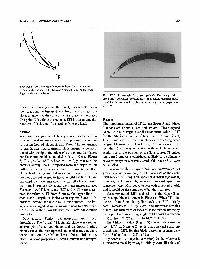
E FIGURE 4 Measurement of eyeline deviation from the anterior airway fine by the angle EIT. E lies on a tangent from I to the lower lingual surface of the blade.
blade shape impinges on the direct, unobstructed view (i.e., IT), then the best eyeline is from the upper incisors along a tangent to the curved under-surface of the blade. The point E lies along this tangent. EIT is thus an angular measure of deviation of the eyeline from the ideal.
Method Accurate photographs of laryngoscope blades with a super-imposed measuring scale were produced according to the method of Hancock and Patel. 19 In an attempt to standardize measurements, blade images were posi- tioned with the tip at the origin of a graph and the blade's handle mounting block parallel with y = 0 (see Figure 5). The position of T is fLxed at x ---- 0, y = 0 and the anterior airway line IT projected from the origin to the outline of the blade incisor surface. To simulate the effect of the blade being inserted to different depths (i.e., air- ways of different incisor to hyoid length) the line IT was increased by 1 cm increments which effectively moved the point I progressively along the blade incisor surface. For each new IT line, angles EIT and M I T were meas- ured for values of IT from 5 cm to the upper limit of each blade's length, as indicated in Figures 3 and 4. In order to increase the accuracy of measurement, the im- ages were enlarged. Angular measurement to better than 0.5 degrees is then possible with the Linex 720 circular protractor.
New unused Penlon Laryngoscopes were used throughout. The "British" Macintosh blade was used as an example of a curved shape, and the Soper 3 adult blade used as the best approximation of a pure straight shape. The adult size Miller 3 was also studied as this blade has some properties of both a curved and straight shape.
FIGURE 5 Photograph of laryngoscope blade. The blade (in this case a size 4 Macintosh) is positioned with its handle mounting block parallel to the x-axis and the blade tip at the origin of the graph (x = 0, y=0).
Results The max imum values of IT for the Soper 3 and Miller 3 blades are about 17 cm and 19 cm. (These depend solely on blade length overall.) Max imum values of IT for the Macintosh series of blades are 15 cm, 12 cm, 10 cm, and 9 cm for the four blades in decreasing order of size. Measurement of M I T and EIT for values of IT less than 5 cm was associated with artifacts on some blades due to the position of the light source: IT values less than 5 cm, were considered unlikely to be clinically relevant except in extremely small children and so were not studied.
In general we should expect that blade curvature causes greater eyeline deviation (i.e., EIT increases as the curve itself blocks the view). This apparent disadvantage might, however, be balanced by increased forward space en- hancement (i.e., M I T could be less with a curved blade), and it would be the combined effect that mattered.
Measurement of M I T and EIT for the Soper 3 la- ryngoscope blade is shown in Figure 6. When IT is in- creased from 5 cm the eyeline deviation, EIT, initially zero, increases to 0.5 ~ by 9 cm, and thereafter remains at 0.5 ~ . Measurement of forward space encroachment by the Soper 3 with increasing length of IT shows a reduction in M I T from 28.25 ~ at 5 cm to 14.5 ~ at 17 cm.
The Miller 3 eyeline (Figure 7) shows little variation from 2.75 ~ at 5 cm to 2 ~ at 19 cm. Forward space en- croachment, MIT, for this blade decreases progressively from 13.0 ~ at 5 cm to 2.8 ~ at 19 cm.
By contrast, EIT (eyeline deviation) for the Macintosh 4 laryngoscope (Figure 8), is initially zero, like that of

266 CANADIAN JOURNAL OF ANAESTHESIA
30
20 u,J m: lO
I,a,,I :m 0
-10
~ M I T
IT (CMS)
FIGURE 6 Soper 3 laryngoscope straight blade. The flat eyeline trace (eyeline angle EIT) is shown. Forward space encroachment (positive MIT) remains high at all values of IT.
I,,IM I,,I.I
l.IJ
3O
2O
K
C
-10
~ EIT
MIT
IT (CMSJ
r 1T IL9
FIGURE 8 Macintosh 4 curved blade. Progressive deviation of the eyeline angle EIT at greater than IT = 7 cm is shown. There is compensation of the eyeline deviation by negative MIT angle with forward space enhancement at greater than IT ----- 11 era.
30
2O
~ - 10 I m !
0 EIT
I I I I I I
ZX CCMS)
FIGURE 7 Miller 3 straight blade with distal curve. The straight blade flat eyeline trace, EIT, and forward space encroachment (positive MIT) are shown.
the Soper 3 and Miller 3 blades, but unlike these blades, beyond 7 cm of IT there is a progressive increase in EIT to a maximum of 9.5 ~ at the blade's maximum IT value of 15 cm. On the other hand, the initial value for forward space encroachment, MIT, is 17.4 ~ at 5 cm, but lessens progressively with increasing IT, becoming zero at 11 cm and -7 ~ by 15 cm.
Analysis of the Macintosh 3 (Figure 9) also shows an EIT of zero until after 7 cm, increasing to a maximum value of 5.9 ~ at 12 cm. There is a similar pattern of reduction in forward space encroachment to the Mac- intosh 4, in that MIT decreases from 19 ~ at 5 cm, to 4).9 ~ by 12 cm.
Eyeline for the Macintosh 2 blade (Figure 10) as for the larger blades, is zero until 7 cm of IT. The maximum EIT is 6.6 ~ at 10 cm. The pattem of forward space en- croachment is unusual because MIT first decreases from
M.I i.a.i r a.nJ d ~
: x
1(3
o
-lO ' -~ ' ~ ' 1~I ' 1'3 '
IT (CMS)
FIGURE 9 Macintosh 3 curved blade. Progressive increase in eyeline deviation angle EIT at greater than IT = 7 cm and forward space enhancement, negative MIT at greater than IT = I 1 cm.
22 ~ at 5 cm to a minimum of 3.5 ~ at 8 cm but then increases again to 6.1 ~ by 10 cm. This late rise in MIT is peculiar to the Macintosh 2 blade.
The Macintosh 1 eyeline (Figure l l) is initially zero, the progressive increase after 5 cm reaching a maximum of 5.6 ~ at 9 cm. The forward space encroachment value for this blade falls progressively from 17 ~ at 5 cm to 11.2 ~ at 9 cm.
Both Soper 3 (Figure 6) and Miller 3 (Figure 7) blades show a distinctive flat eyeline trace. This is in contrast to the curved Macintosh blades which after an initial flat trace show a progressive increase in EIT with in- creasing length of IT. The Soper 3 exhibits the lowest EIT values of all the blades tested. The Miller 3 shows higher EIT values than the Soper 3, but lower than any EIT for curved blades. The Macintosh 4 blade (Figure 8) has the highest EIT values of all the blades tested.

Marks et al.: LARYNGOSCOPE BLADES 267
MJ
3O
2O .
10
0 i
MIT
IT (CMS)
FIGURE 10 Macintosh 2 curved blade. Progressive increase in eyeline deviation angle at greater than IT = 7 cm. Forward space encroachment angle MIT falls progressively to IT = 8 cm but rises again after IT = 9 cm.
3O
20-
~ " 10- LU 0
~ : : MIT
_ _ _ ~ EtT
IT fCMS)
FIGURE 11 Macintosh 1 curved blade. Progressive rise in eyeline deviation angle EIT from IT = 5 cm. Forward space encroachment angle MIT remains high with little improvement against increasing IT.
The other three curved blades share a similar range of values which are intermediate between the straight blades and the Macintosh 4.
The lowest MIT values are shown by the two larger curved blades which are the only ones achieving negative MIT values with forward space enhancement. The Mac- intosh 4 exhibits the lowest MIT values of all the blades analyzed. Neither of the small curved blades achieve neg- ative MIT values. The Soper 3 blade fairs worst in terms of forward space encroachment with the highest MIT values of all the blades tested.
In order to interpret the measurements of the eyeline deviation and forward space encroachment (or enhance- ment) a combination score was produced from simple addition of EIT and MIT on the basis that an increase in magnitude of either angle represents a deterioration in performance of the laryngoscope blade for any given value of IT. Figure 12 compares the Soper 3 straight blade, Miller 3 straight blade with distal curve, and the Macintosh 4 curved blade in terms of their combination scores. The Macintosh curved blade shows the lowest ovemU range of combination scores. The Miller 3 com- bination score lies between the curved blade and the straight Soper 3 blade. Combination score for the Mac- intosh series of blades are shown in Figure 13. Both the Macintosh 3 and 4 blades show progressive reduction in combination score with increasing IT. The longer Mac- intosh 4 blade has the lowest combination scores. The deterioration in performance of the Macintosh 2 blade in terms of increasing combination score at IT values greater than 8 cm is well shown. The Macintosh 1 com- bination score is a remarkably flat trace with little im- provement as IT increases.
3O
LM, I ~ 2 C
I,-,., B
E + -'[ i.,.,,. m IL l
~ SOPER
IT (CMS) FIGURE 12 Combination scores for the Soper 3, Miller 3, and Macintosh 4 laryngoscope blades.
3O
~. ~ M A G 1 I'm MAC 2
'X
FIGURE 13 Combination scores for the Macintosh series of blades. The smaller size 1 and 2 blades are quite different from the larger size 3 and 4 blades.

268 C A N A D I A N J O U R N A L O F A N A E S T H E S I A
Discussion Despite possessing the lowest eyeline deviation score of all, the straight Soper 3 blade has the highest MIT and therefore worst combination score on account of the high values for forward space encroachment. The significance of high forward space encroachment is that in difficult intubating situations where forward space is limiting, it may be impossible for the blade to be positioned with
�9 the tip in contact with the hyoid point. As a result, al- though the eyeline to the Soper blade tip is excellent, elevation of the epiglottis with laryngeal exposure may be prevented. Clearly, when forward space is not limiting, the Soper blade achieves minimal eyeline deviation with a straight line view of the vocal cords. Soper uses the same Z-shaped cross-section as the Macintosh blade. Soper considered this to be superior to the C-shaped cross-section of other "orthodox" straight blades used at the time. Soper's justification for a straight blade was that, with a curved shape, a "stiffener" was sometimes needed in order to pass the endotracheal tube around the curve and into the larynx. 2~ This advantage of a straight shape claimed by Soper now seems tenuous with the advent of modem endotracheal tubes not requiring a "stiffener."
Miller's blade shows an improvement in combination score over the pure straight shape. There is a small eyeline deviation (maximum of 4.5 ~ ) which results from the distal curved part of the shape. The distal curve also contributes to the lesser forward space encroachment when compared with the Soper. This is because the blade tip extends beyond the rest of the shape. This means that when the blade tip contacts the hyoid point, less of the blade is forward of the anterior airway line and hence the lower MIT angle. The fact that the blade is narrower than the Soper also contributes to its lower forward space en- croachment. Miller claimed that his narrower blade al- lowed the mouth to be open less widely at laryngoscopy. He remarked, "This allows freer anterior movement of the mandible which in itself is an aid in obtaining better exposure. "2~ The implication of "freer anterior movement of the mandible" is that available forward space (the space between the blade and the mandible) is increased by the Miller blade compared with other straight blades that were available in 1941.
The lowest and best combination scores are achieved by the Macintosh size 3 and 4 curved blades. Both exhibit higher eyeline deviation than either the Soper or Miller blades but possess low combination scores on account of low forward space encroachment. The high eyeline deviation of Macintosh blades is a direct effect of the curved shape. When the blade tip contacts the hyoid point the bend of the blade is clearly in the way of a direct
view of the tip. Apparently the original Macintosh design had a "slight but distinct flattening near the mid-point ... On the principle that one cannot see through the crest of a hill. "22 This would appear to be an attempt to reduce eyeline deviation caused by the curved shape. Unfortu- nately when stainless steel was first used for blade man- ufacture in 1956 it was not possible to press a shape with mid-point flattening due to the more springy prop- erty of steel compared with previously used chromium plated brass, 22 and the flat mid-point now seems to have disappeared from the curve.
The two larger Macintosh blades are distinct in ex- hibiting forward space enhancement with negative MIT values. Forward space enhancement is an effect attrib- utable to the curve. It occurs when the concavity of the curve passes behind the anterior airway line at the level of the mandible. It is not possible for either the Soper or Miller shapes to achieve forward space enhancement since both are flat at the level of the anterior airway line. With Macintosh 3 and 4 blades, forward space enhance- ment occurs for values of IT greater than 11 cm. Eyeline deviation with these blades does not begin until after 7 cm IT, and only exceeds that of the straight blades after 9 cm. The increased eyeline deviation of the curved shape is offset by forward space enhancement with negative MIT after I 1 cm. The forward space enhancement after 11 cm of IT is clinically relevant since the range of values obtained for IT from our accumulated data in adults is from 9.5 to 14.5 cm. The Macintosh 4 blade shows the greatest degree of forward space enhancement and this may represent an advantage over the Macintosh 3 blade when IT is greater than 12 cm. There is little dif- ference between the two shapes for IT lengths of less than 12 cm.
Macintosh remarked on two occasions that "the precise shape or curve of the blade does not seem to matter much provided the tip does not go beyond the epiglot- tis. "23'24 The curve of the Macintosh blade was designed with the intention of positioning the tip "into the angle made by the epiglottis with the base of the tongue. "23 Such a placement does achieve blade tip-hyoid contact as described in this paper. Macintosh did not allude to the forward space enhancing property of his blade other than to say "I find a curved blade easy to introduce" without any further qualilication. 24 However, he did cite the curved shape as being advantageous for passage of the curved Magill-type endotracheal tube. 24 Cassels ap- peared to recognize the potentially greater laryngeal ex- posure possible with a curved blade when space is re- stricted, but he considered the gap between the upper and lower teeth to be the important space restriction rather than forward space at the level of the mandible. 8

Marks et al.: LARYNGOSCOPE BLADES 269
Furthermore, the "curved" blade illustrated in Cassels' 1942 paper, which pre-dates the Macintosh design, is a predominantly straight shape with a distal curve.
The Macintosh 2 combination score graph is inter- esting (Figure 13). Whilst the blade shows some advan- tage over the larger blades for IT values of 8 cm and less, there is a marked deterioration in score at IT greater than 8 cm such that it is inferior to the larger Macintosh 3 and 4 size blades. The increase in score at > 8 cm of IT with the Macintosh 2 blade is because forward space enhancement does not occur with this blade and MIT increases after 9 cm. This means that the charac- teristic curved blade eyeline deviation is not compensated.
The Macintosh 1 blade shows the worst performance and highest combination score of all the curved blades (Figure 13). The blade does not have the advantage of a curved shape in that MIT shows very little improvement with increasing IT, yet the blade still possesses the eyeline deviation of a curved shape. In other words the Mac- intosh 1 has the disadvantageous eyeline deviation of a curved blade and also the high MIT values more in keeping with a straight blade. The designer of the size 1 Macintosh blade is not known, but the shape was ap- parently condemned by Macintosh as "anatomically wrong. "22 Robertshaw observes that the larger Macintosh blades could be used "even in the newborn" but that the smaller sized blades were "much too curved. "2s We have no information on the clinical range of IT for chil- dren but a value of 8 cm or greater would mean that the Macintosh 2 blade is inferior to the larger curved blades according to our criteria. The concept of available forward space limiting laryngoscopy was derived from adult data and hence the significance of forward space encroachment by the paediatric size Macintosh blades re- mains unclear. Despite this, it is relevant that the two smaller blades are quite different in shape, in terms of MIT and EIT, than the larger size 3 and 4 blades. Our own subjective experience is that the smaller size Mac- intosh blades are inferior to the two larger sizes for pae- diatric anaesthesia. It is interesting that Miller initially advocated only one size of laryngoscope for tracheal in- tubation in patients of all ages. 21
Theoretical prediction of laryngoscope blade perform- ance in terms of eyeline deviation and forward space en- hancement and encroachment supports the view that a curved blade is superior to a straight one, 8 and that the smaller Macintosh blades are comparatively poor per- formers. 22,25 Whilst our method produces MIT and EIT values for comparison of different blades, it is not possible to say what the absolute numerical value is for a bad MIT or EIT unless the anatomical values of IT JS and IC are known in a particular circumstance. Eyeline de-
viation has been calculated with the blade tip as the zero reference point. The laryngeal opening is actually some distance behind the blade tip at laryngoscopy and hence EIT measurement may overestimate eyeline deviation from the laryngeal opening. The combination score is produced by simple addition of EIT and MIT. This may prove to be an over-simplification, although each angle influences laryngoscopy such that an increase in its mag- nitude predicts a worse view. Measurement of MIT was from the anterior airway line. The position of the man- dible (where forward space effects are thought to be most important) has been assumed to be along a perpendicular from C on IT such that IC = IT/3. Angle MIT is meas- ured along this line. The value of IC = IT/3 has been derived from measurements of x-ray laryngoscopy. The ratio IC:IT may well be altered in difficult intubation. This will result in different MIT values.
Throughout our work we have assumed that position- ing of the blade along the IT axis was possible and thus our measurements are a reflection of the properties in- trinsic to laryngoscope blade shape. We have not attemp- ted to predict the view when there are limitations on mouth opening or restricted neck movement, although both would be likely to restrict forward space.
It is important to point out that the Soper and Miller blades were designed for direct elevation of the epiglottis whilst the Macintosh blade is intended for indirect epi- glottic elevation. Forward space restriction is likely to ef- fect both mechanisms in a similar fashion since both di- rect and indirect epiglottic elevation require similar blade tip positioning and similar epiglottic elevation for laryn- geal exposure. Furthermore, the straight blades may be used for indirect epiglottic elevation.
Over the years, many promising laryngoscope designs have fallen by the wayside without any objective eval- uation. In our view simple comparative clinical trials, in the present state of knowledge, would require stringent conditions, be time consuming and might still give un- certain results. It should be noted that curved blades even of the same generic type and size from different man- ufacturers are not necessarily exactly the same shape. Our information from Penlon Ltd was that the original Mac- intosh designs were from simple pencil line drawings which are not now available. This study underlines the relevance of laryngoscope blade shape and establishes a theoretical reproducible method for performance analysis. The values obtained for standard straight and curved blades may be considered as yardsticks against which future developments in blade design can be compared. It would appear reasonable to suggest even on the basis of the limited information available thus far that the blades studied can probably be improved on. A blade

270 CANAD1ANJOURNALOFANAESTHES1A
with a combination score close to zero for its whole length would seem feasible.
Acknowledgement We are grateful to Penton UK Limited for making avail- able a complete range of unused laryngoscopes.
References 1 Mclntyre JWR. Laryngoscope design and the difficult
adult tracheal intubation. Can J Anaesth 1989; 36: 1: 94-8. 2 Phillips OC, Duerksen RL. Endotracheal intubation: a
new blade for direct laryngoscopy. Anesth Analg 1973; 52: 4: 691-8.
3 Gabuya R, Orkin LR. Design and utility of a new curved laryngoscope blade. Anesth Analg 1959; 38: 5: 364-9.
4 Bainton CR. A new laryngoscope blade to overcome pha- ryngeal obstruction. Anesthesiology 1987; 67: 767-70.
5 Portzer M, Wasmuth CE. Endotracheal anesthesia using a modified Wis-Foregger laryngoscope blade. Cleve Clin Q 1959; 26: 140-3.
6 SchapiraM. A modified straight laryngoscope blade de- signed to facilitate endotracheal intubation. Anesth Analg 1973; 52: 553-4.
7 Bizzarri DV, Giuffrida JG. Improved laryngoscope blade designed for ease of manipulation and reduction of trauma. Anesth Analg 1958; 37: 231-2.
8 Cassels WH. Advantages of a curved laryngoscope. Anes- thesiology 1942; 3: 580-1.
9 Racz GB. Improved vision modification of the Macintosh laryngoscope (Correspondence). Anaesthesia 1984; 39: 1249-50.
10 Bryce-Smith R. A laryngoscope blade for infants. BMJ 1952; 1: 217.
11 Snow JC. Modification of laryngoscope blade. Anesthesi- ology 1962; 23: 394.
12 Williams KN, Carli F, Cormack RS. Unexpected, difficult laryngoscopy: a prospective survey in routine general surgery. Br J Anaesth 1991; 66: 38-44.
13 Horton WA, Fahy L Charters P. Defining a standard intu- bating position using "angle finder." Br J Anaesth 1989; 62: 6-12.
14 Horton WA, Fahy L Charters P Factor analysis in diffi- cult tracheal intubation: laryngoscopy-induced airway ob- struction. Br J Anaesth 1990; 65: 801-5.
15 Horton WA, Fahy I_, Charters R Disposition of cervical vertebrae, atlanto-axial joint, hyoid and mandible during x-ray laryngoscopy. Br J Anaesth 1989; 63: 435-8.
16 Jackson C. The technique of insertion of intratracheal in- sufflation tubes. Surg Gynecol Obstet 1913; 17: 507-9.
17 Fahy L, Horton WA, Charters P Factor analysis in pa- tients with a history of failed tracheal intubation during pregnancy. Br J Anaesth 1990; 65: 813-5.
18 Horton WA, Fahy I_, Charters P. Towards a single index
for quantifying osseous factors in difficult laryngoscopy. Br J Anaesth 1990; 65: 583-4P.
19 Hancock R, Patel BC. Clinical photography: a method of accurate documentation. J Audiov Media Med 1989; 12: 154-5.
20 Soper RL. A new laryngoscope for anaesthetists. BMJ 1947; 1: 265.
21 Miller RA. A new laryngoscope. Anesthesiology 1941; 2: 318-20.
22 Jephcott A. The Macintosh laryngoscope. A historical note on its clinical and commercial development. Anaesthe- sia 1984; 39: 474-9.
23 Macintosh RR. A new laryngoscope. Lancet 1943; 1: 205. 24 Macintosh RR. Laryngoscope blades (Correspondence).
Lancet 1944; 1: 485. 25 Robertshaw FL. A new laryngoscope for infants and chil-
dren. Lancet 1962; 2: 1034.