equipment marking requirements - iaei western...
TRANSCRIPT

This is a photographic template – yourphotograph should fit precisely within this rectangle.
International Association of Electrical InspectorsWestern Section Meeting
Louisville, KYS t b 19 2011September 19, 2011
Equipment Marking RequirementsThomas Domitrovich David Bredhold
© 2010 Eaton Corporation. All rights reserved.
Thomas Domitrovich David Bredhold
2 2

The Importance of Labeling
3 3

4 4
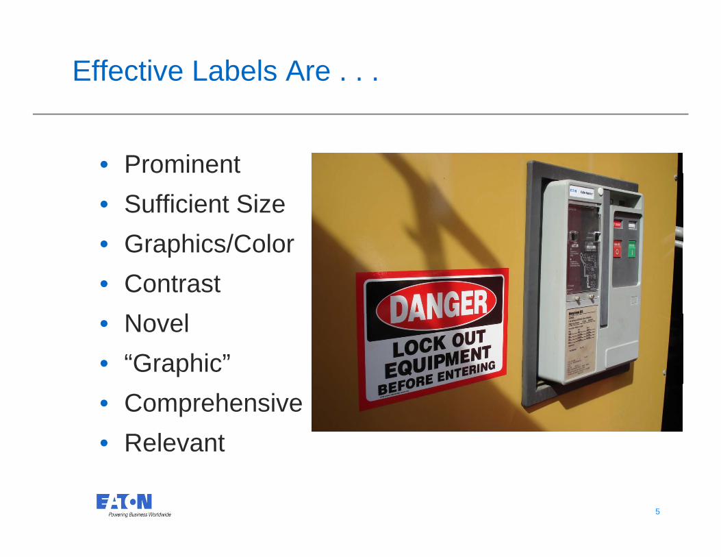
Effective Labels Are . . .
• Prominent• Sufficient Size• Graphics/Color• Graphics/Color• Contrast
N l• Novel• “Graphic”• Comprehensive• Relevant
5 5
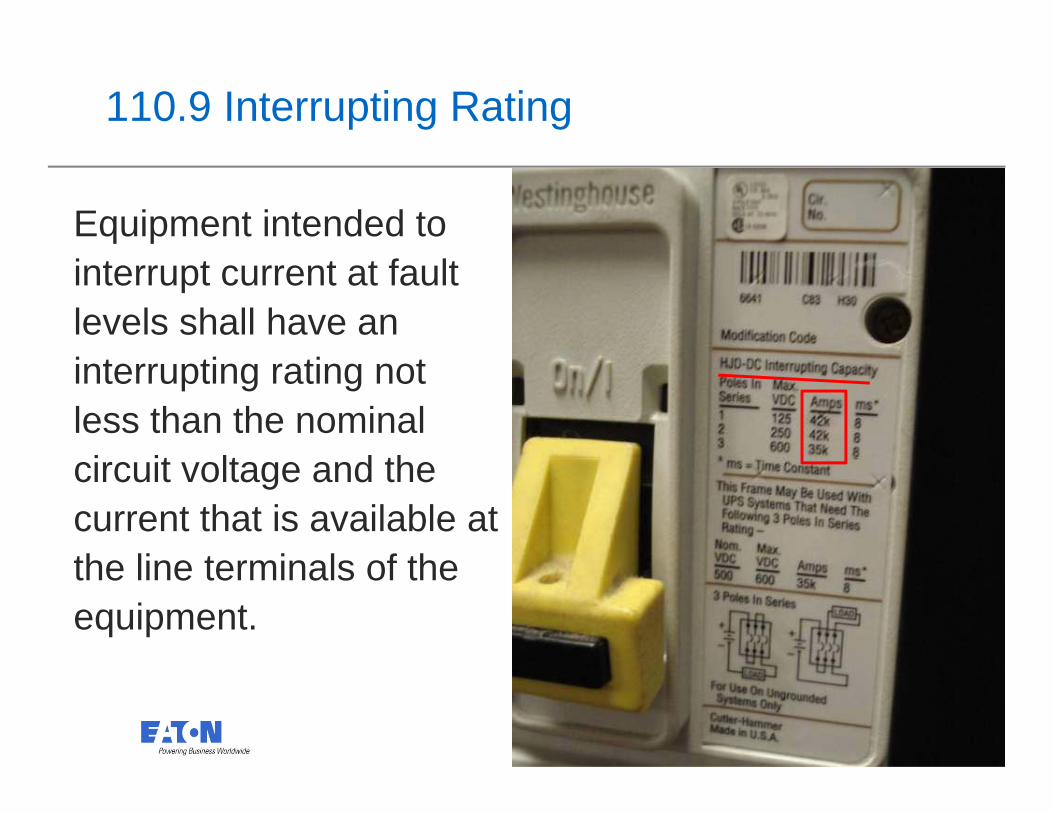
110.9 Interrupting Rating
Equipment intended to interrupt current at fault levels shall have an interrupting rating not less than the nominal i it lt d thcircuit voltage and the
current that is available at the line terminals of thethe line terminals of the equipment.
6 6
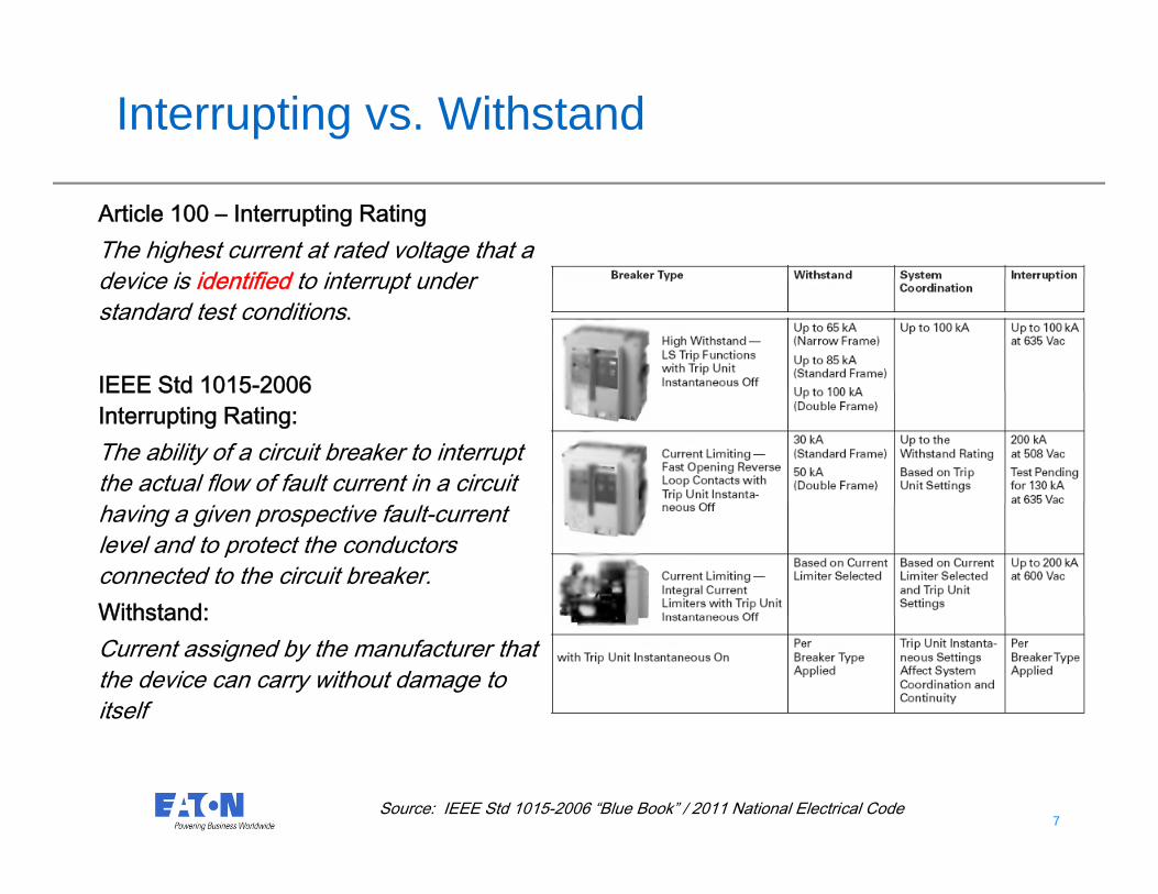
Interrupting vs. Withstand
Article 100 – Interrupting RatingThe highest current at rated voltage that a device is identified to interrupt underdevice is identified to interrupt under standard test conditions.
IEEE Std 1015-2006IEEE Std 1015 2006 Interrupting Rating:The ability of a circuit breaker to interrupt the actual flow of fault current in a circuit having a given prospective fault-current level and to protect the conductors connected to the circuit breaker.Withstand:Withstand:Current assigned by the manufacturer that the device can carry without damage to itself
7 7Source: IEEE Std 1015-2006 “Blue Book” / 2011 National Electrical Code

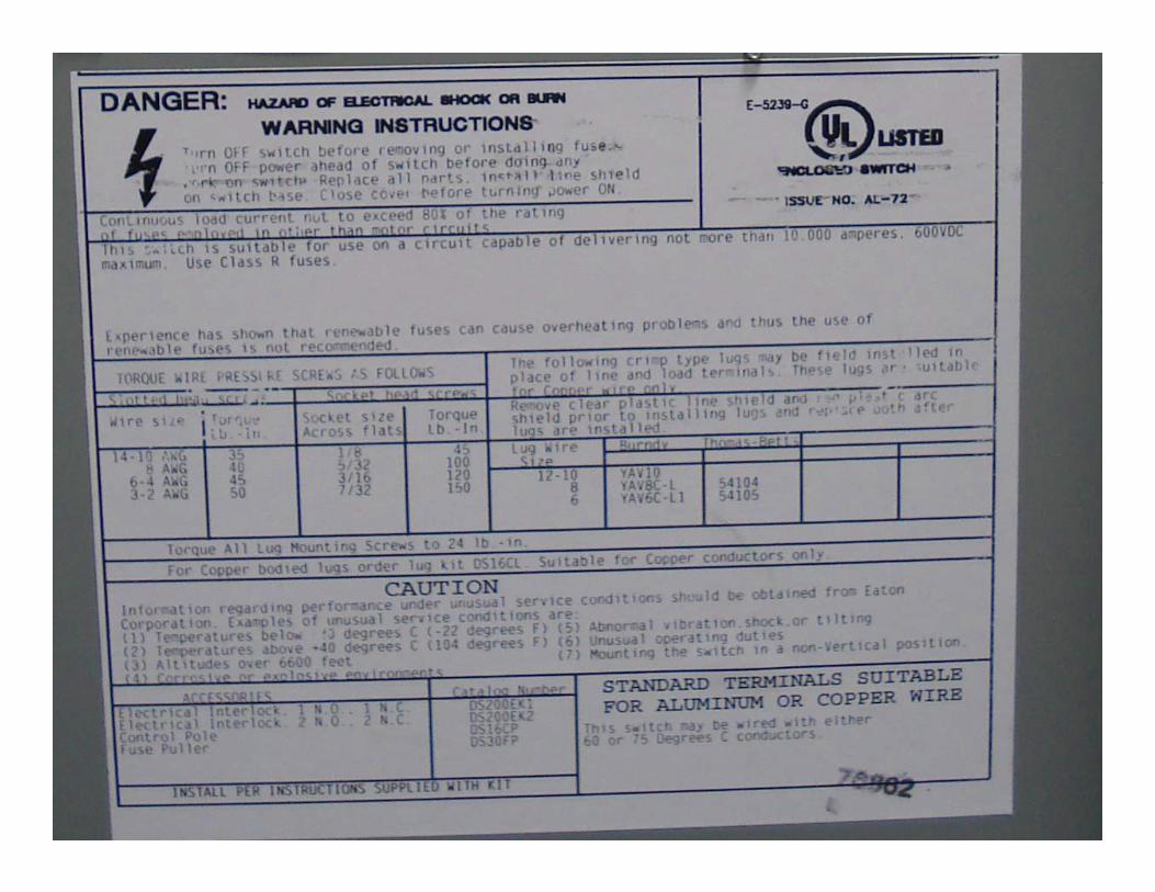
110.14(C) Electrical Connections
(1)Equipment Provisions(a)(1) Conductors rated 600C (1400F)(a)(1) Conductors rated 60 C (140 F).
(3) Conductors with higher temperature ratings if the equipment is listed and identified for use with q psuch conductors.
Terminals identified for use with 750C conductors
8 8
9 9

110.15 High-Leg Marking
Four-wire delta systems, where one leg is grounded.y g gOnly the leg having the higher voltage to ground—marked by orange color or other effective means.
10 10

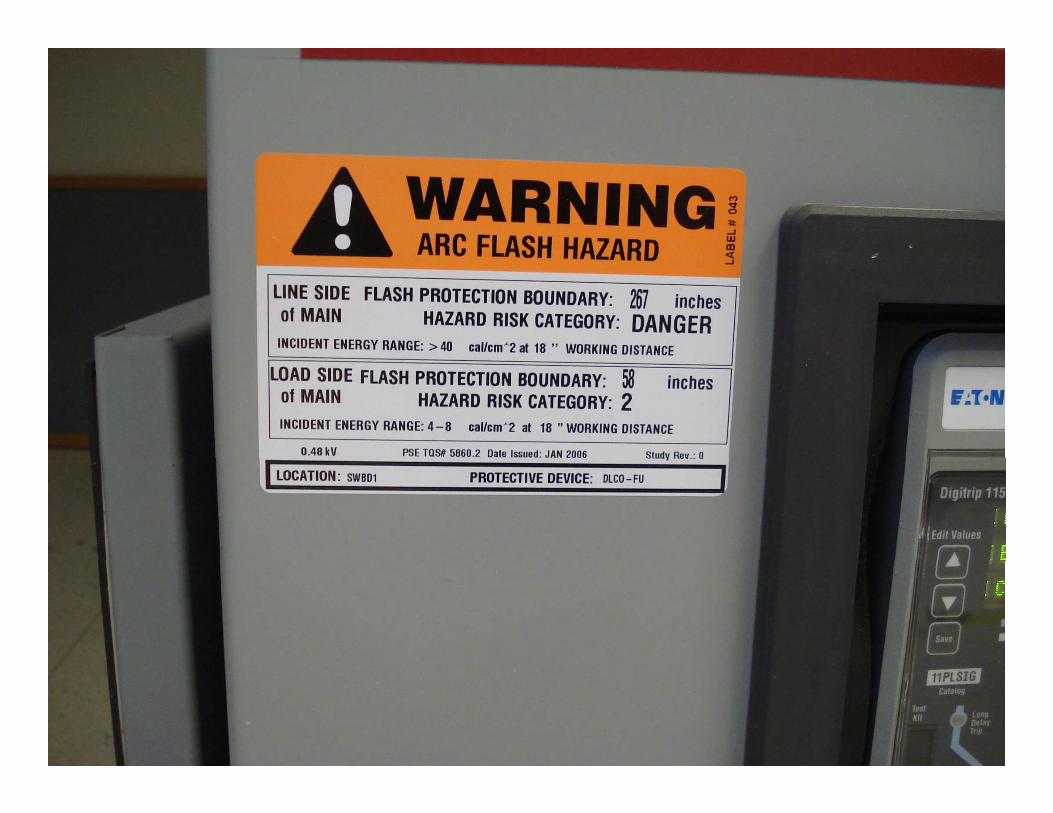
110.16 Arc-Flash Warning
Other than dwelling units:Equipment likely to require examinationEquipment likely to require examination, adjustment, servicing, or maintenance while energized– field-marked to warn qualifiedenergized– field-marked to warn qualified persons of potential arc flash hazards.
11 11Labels--Brady Worldwide ©
12 12

13 13
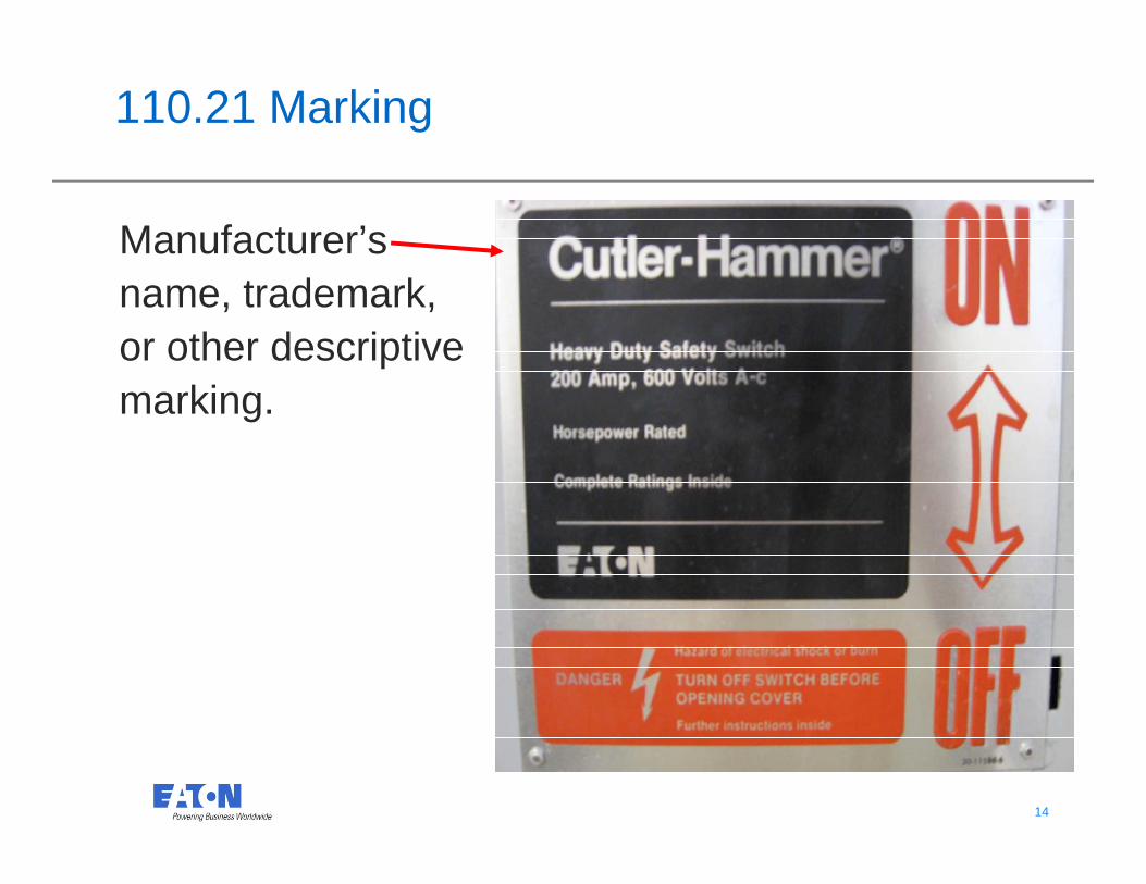
110.21 Marking
Manufacturer’s name, trademark, or other descriptive
kimarking.
14 14
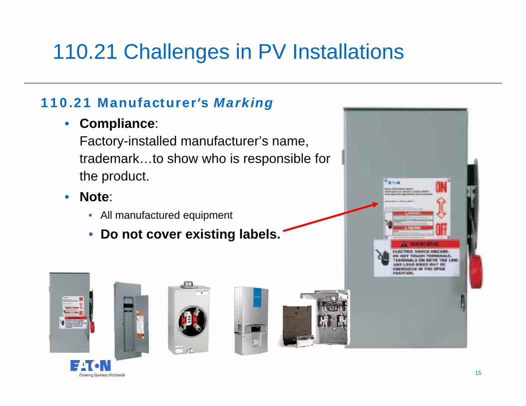
110.21 Challenges in PV Installations
110.21 Manufacturer’s Marking
• Compliance:Compliance:Factory-installed manufacturer’s name, trademark…to show who is responsible for the productthe product.
• Note:• All manufactured equipment
• Do not cover existing labels.
15 15

110.22 Identification of Disconnecting Means
(A) General. Each disconnecting h ll b l ibl k dmeans shall be legibly marked
to indicate its purpose…
16 16
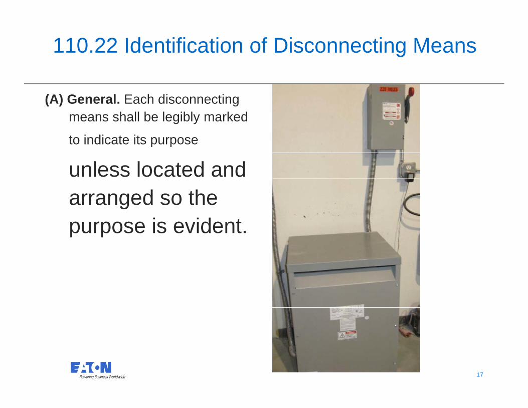
110.22 Identification of Disconnecting Means
(A) General. Each disconnecting means shall be legibly marked
to indicate its purpose
unless located and arranged so the purpose is evidentpurpose is evident.
17 17
Disconnecting Means Labeling for PV
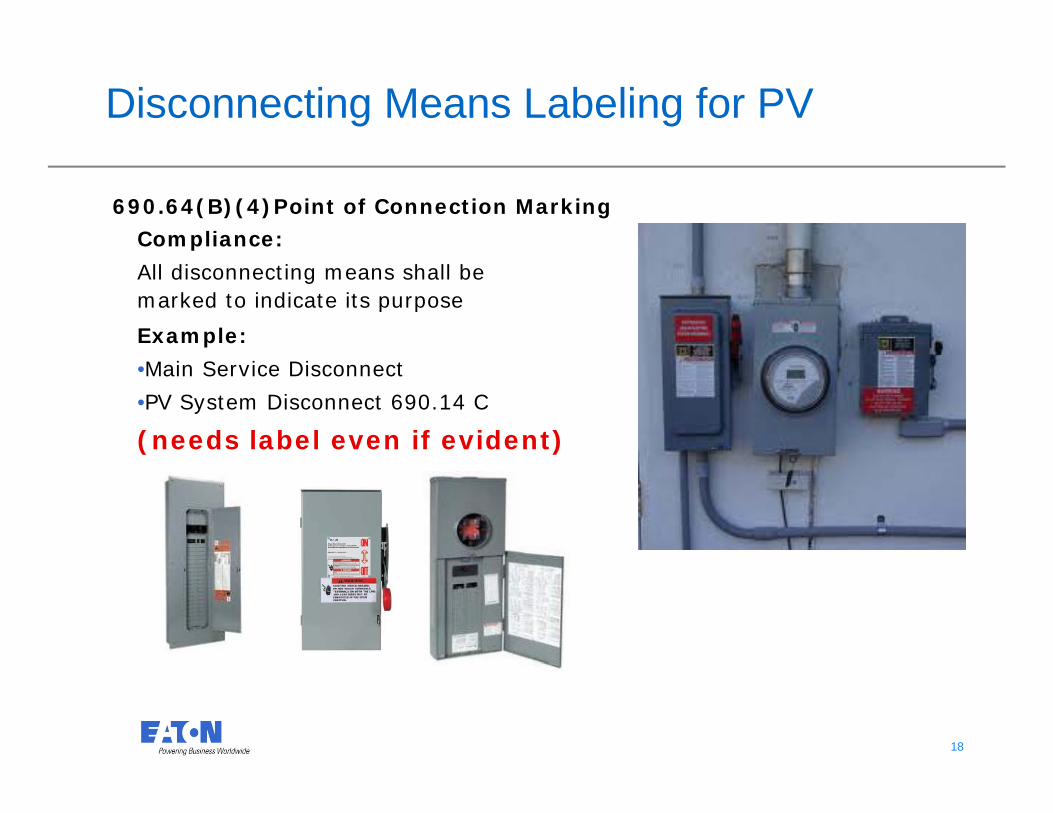
Compliance:
690.64(B)(4)Point of Connection Marking
All disconnecting means shall be marked to indicate its purpose
Example:
•Main Service Disconnect
•PV System Disconnect 690.14 C
(needs label even if evident)
18 18
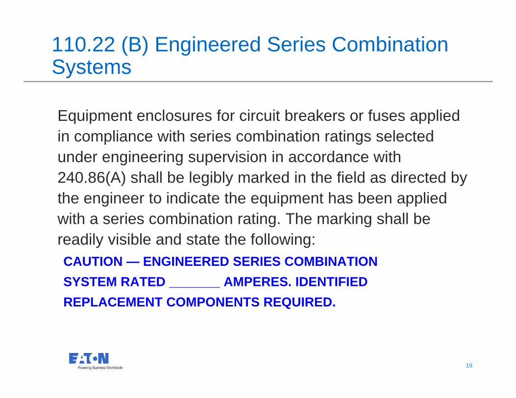
110.22 (B) Engineered Series Combination SystemsSystems
Equipment enclosures for circuit breakers or fuses applied q p ppin compliance with series combination ratings selected under engineering supervision in accordance with 240 86(A) h ll b l ibl k d i th fi ld di t d b240.86(A) shall be legibly marked in the field as directed by the engineer to indicate the equipment has been applied with a series combination rating. The marking shall be g greadily visible and state the following:CAUTION — ENGINEERED SERIES COMBINATIONSYSTEM RATED _______ AMPERES. IDENTIFIEDREPLACEMENT COMPONENTS REQUIRED.
19 19

Series Ratings
ExampleBreaker A
Available Fault Current = 50KA
Breaker B• Breaker A Rated For 65KA
• Breaker B Rated ForBreaker B Rated For 10KA
Under Normal CircumstancesUnder Normal Circumstances, Breaker B Would Not Be
Acceptable. A Series Rated Combination Would Be Acceptable
20 20
Combination Would Be Acceptable
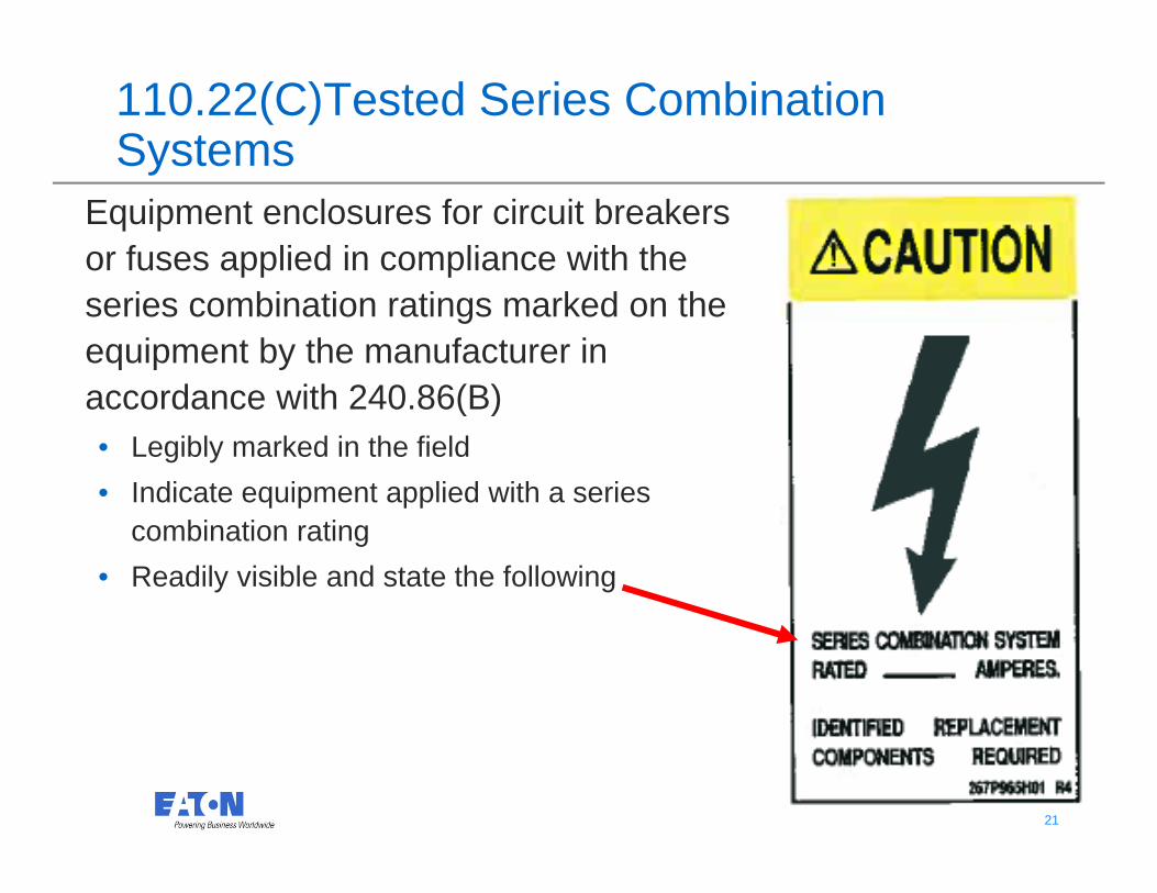
110.22(C)Tested Series Combination SystemsSystems
Equipment enclosures for circuit breakers or fuses applied in compliance with the series combination ratings marked on the equipment by the manufacturer in
d ith 240 86(B)accordance with 240.86(B) • Legibly marked in the field • Indicate equipment applied with a series q p pp
combination rating• Readily visible and state the following
21 21

22 22
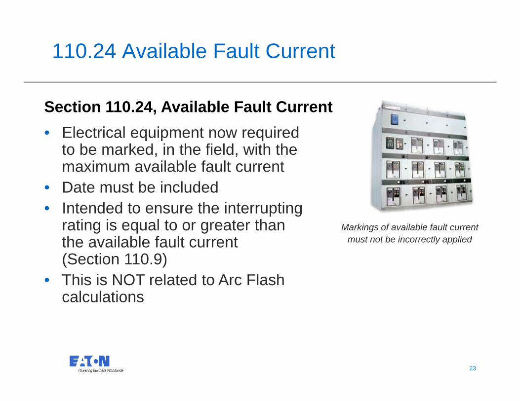
110.24 Available Fault Current
Section 110.24, Available Fault Current• Electrical equipment now required
to be marked, in the field, with the maximum available fault current
• Date must be included• Intended to ensure the interrupting
rating is equal to or greater than Markings of available fault currentrating is equal to or greater than the available fault current (Section 110.9)Thi i NOT l t d t A Fl h
Markings of available fault current must not be incorrectly applied
• This is NOT related to Arc Flash calculations
23 23
110.24 Available Fault Current (contd.)
(B) Modifications. When modifications to theelectrical installation occur that affect theelectrical installation occur that affect the maximum available fault current at the service, the maximum available fault current shall be
ifi d l l t d Th i d fi ldverified or recalculated... The required field marking(s) in 110.24(A) shall be adjusted to reflect the new level of maximum availablereflect the new level of maximum available fault current.
(What happens when new fault current level exceeds rating of equipment??)
24 24

Fault Current in a SystemInfinite Bus Calculation
Unlimited Fault Current Note:12,470VΔ
2,500 kVA, Z = 5.75%
Calculated Fault12 Feet, 3,200A Copper Feeder Busway
Obtain specific impedancevalues for each system.Do not assume the valuesshown here will be typical.
*52,296A480Y/277V , , pp y
3,200A3,200A Bus
60 F t 200A 200A 150A 100 Feet60 Feet(3) 1-Conductor#4/0 CopperTHW InsulationSteel Conduit
200A 200A 150A 100 Feet(3) 1-Conductor1/0 CopperTHW InsulationSteel Conduit
MainControlPanel
*64,324A when motor contribution added
25 25
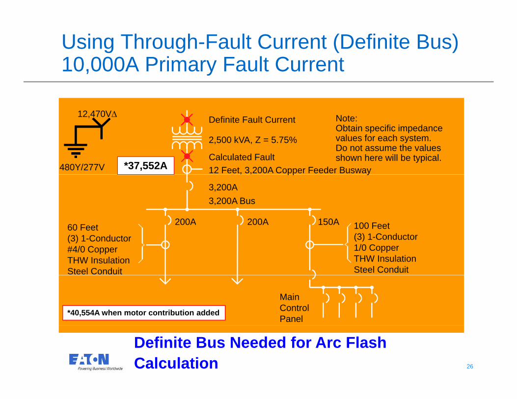
Using Through-Fault Current (Definite Bus)10,000A Primary Fault Current, y
Definite Fault Current Note:12,470VΔ
2,500 kVA, Z = 5.75%
Calculated Fault12 Feet, 3,200A Copper Feeder Busway
Obtain specific impedancevalues for each system.Do not assume the valuesshown here will be typical.
*37,552A480Y/277V , , pp y
3,200A3,200A Bus
60 F t 200A 200A 150A 100 Feet60 Feet(3) 1-Conductor#4/0 CopperTHW InsulationSteel Conduit
200A 200A 150A 100 Feet(3) 1-Conductor1/0 CopperTHW InsulationSteel Conduit
MainControlPanel
*40,554A when motor contribution added
26 26
Definite Bus Needed for Arc Flash Calculation
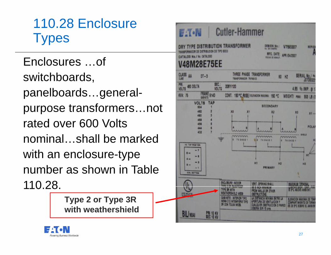
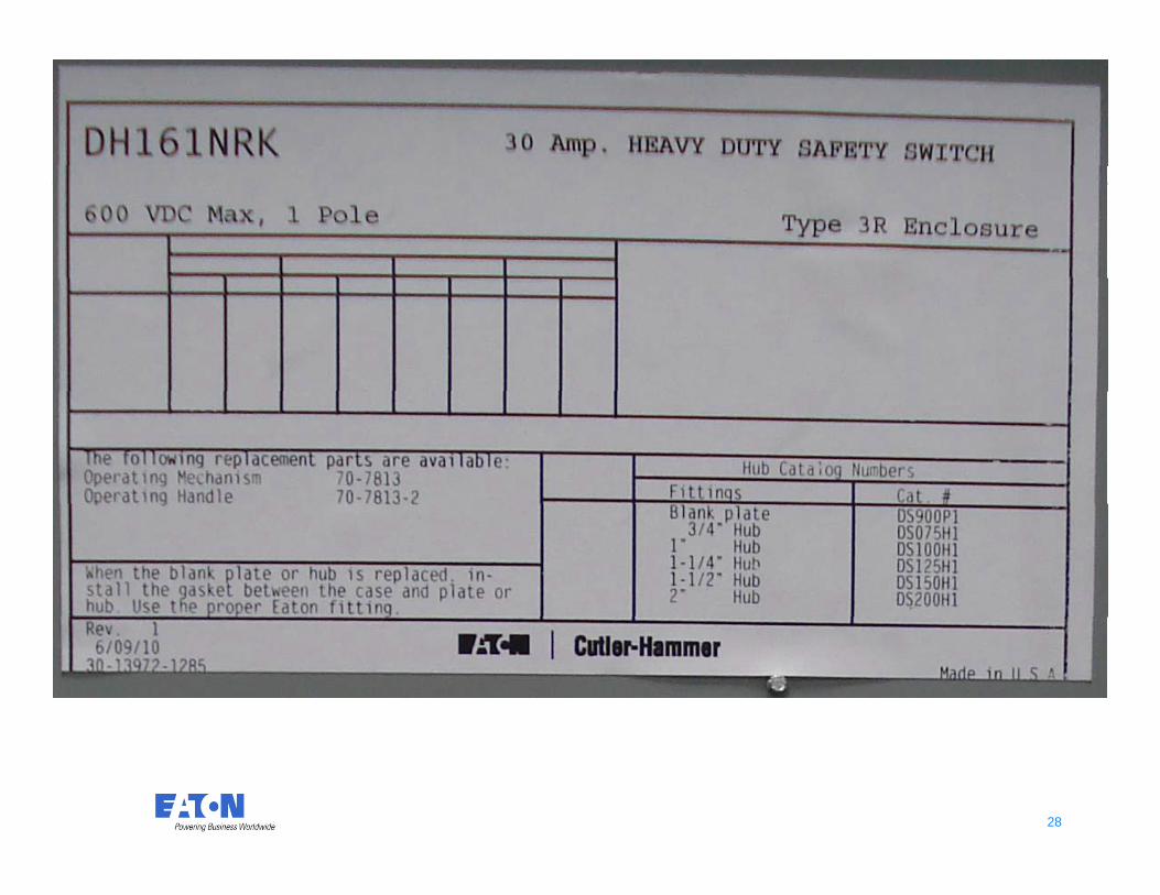
110.28 EnclosureTypes
Enclosures …of switchboardsswitchboards, panelboards…general-purpose transformers…notpurpose transformers…not rated over 600 Volts nominal…shall be marked with an enclosure-type number as shown in Table
Type 2 or Type 3R ith eathershield
110.28.
27 27
with weathershield
28 28
110.34(C)Locked Rooms or Enclosures (Over 600 Volts)(Over 600 Volts)
Where the voltage exceeds 600 volts, nominal, g , ,permanent and conspicuous signs shall be provided, reading as follows:p , g
DANGER—HIGH VOLTAGE—KEEP OUTDANGER—HIGH VOLTAGE—KEEP OUT
(Wh i ibl f idi i ??(Who is responsible for providing signage??NEC is not specific.)
29 29
NEC 225.70 Substations
(A) Warning Signs( ) g g(1) General
Warning notice “DANGER—HIGH VOLTAGE”Warning notice DANGER HIGH VOLTAGE(1) At all entrances(2) At points of access to conductors on all high-( ) po s o access o co duc o s o a gvoltage conduit and cable systems(3) On all cable trays( ) y
30 30
NEC 225.37 Outside Circuit Identification
Where a building or structure has any combination f f d b h i it i iof feeders, branch circuits, or services passing
through it or supplying it, a permanent plaque or directory shall be installed at each feeder anddirectory shall be installed at each feeder and branch-circuit disconnect location denoting all other services feeders or branch circuits supplying thatservices, feeders, or branch circuits supplying that building or structure or passing through that building or structure and the area served by eachbuilding or structure and the area served by each.
31 31
NEC 230.2 Number of Services—Identification
230.2(E) Where a building or structure is ( ) gsupplied by more than one service, or any combination of branch circuits, feeders, and branch circuits, a permanent plaque or directory shall be installed at each location denoting all other services, feeders, and branch circuits supplying that building or structure. See 225.37
32 32

NEC PV System Directory Labeling
Compliance:
705.10 Directory PV System Disconnect
Must have a plaque or directory giving the location of the other power source disconnecting means.
Compliance:
Utility Meter
Main Service Disconnect
Utility Meter
At the AC service disconnecting means and the DC disconnect(s)
Label Location:
and the DC disconnect(s)
Label Wording (Example):
AC Service Disconnect
PV System disconnecting means located PV System disconnecting means located outside on the north wall.
PV System Disconnect
Utilit i di t i l t d I id
33 33
Utility service disconnect is located Inside on the Southwest corner wall.
NEC 230.44 ServicesCable TraysCable Trays
Such cable trays shall be identified with tl ffi d l b l ith th dipermanently affixed labels with the wording
“Service-Entrance Conductors.” The labels shall be located so as to be visible after installation andbe located so as to be visible after installation and placed so that the service-entrance conductors are readily traced through the entire length of thereadily traced through the entire length of the cable tray.
34 34

NEC 230.66 Service Equipment—Marking
Service equipment rated at 600 volts or less shall be marked to identify it as being suitable for use as service equipment.
35 35

NEC 230.72 Grouping of Disconnects
(A) General.The two to six disconnects as permitted in 230.71 shall be grouped. Each disconnect shall be marked to indicate the load served.
36 36
NEC 250.21(C)
Marking. Ungrounded systems shall be legibly g g y g ymarked “Ungrounded System” at the source or first disconnecting means of the system.g y
37 37

NEC 310.120 Conductor and Cable Marking
(A) Required Information.( ) q(1) Maximum rated voltage(2) Proper type letter or letters for type of wire(3) Manufacturer’s name, trademark, or other distinctive
marking(4) AWG size or circular mil area.(5) Cable assemblies where the neutral conductor is
ll th th d d d tsmaller than the ungrounded conductors.
38 38
NEC 392.18(H) Cable Tray Marking
Cable trays containing conductors rated over y g600 volts shall have a permanent, legible warning notice carrying the wording g y g g“DANGER—HIGH VOLTAGE—KEEP AWAY” placed on all cable trays, with the spacing of warning notices to exceed 10 ft.
39 39

NEC 400.6 Flexible Cords
(A) Standard Markings. Flexible cords and ( ) gcable shall be marked by means of a printed tag attached to the coil reel or carton. The tag g gshall contain the information required in 310.120(A).(B) Optional Markings. Flexible cords and cable types listed in Table 400.4 shall be yppermitted to be surface marked…
40 40

NEC 408.3 Switchboards and Panelboards
(F) Switchboard and Panelboards Identification.( )(1)High-Leg Identification. Switchboards or panel
board containing a 4-wire delta-connectedboard containing a 4 wire, delta connected system where the mid-point of one phase winding is grounded shall be legibly and d g s g ou ded s a be eg b y a dpermanently field marked as follows:“Caution Phase Has Volts to Ground”____ ____
41 41

NEC 408.4 Switchboards and PanelboardsField Identification RequiredField Identification Required
(A) Circuit Directory or Circuit Identification.( ) yEvery circuit and circuit modification shall be legibly identified as to its clear evident andlegibly identified as to its clear, evident, and specific purpose.
(B) Source of Supply All switchboards and(B) Source of Supply. All switchboards and panelboards supplied by a feeder in other than one- or two-family dwellings shall be marked toone or two family dwellings shall be marked to indicate the device or equipment where the power supply originates.
42 42
power supply originates.

PV Systems Also Require Identification
408.4 Circuit Directory or Circuit Identification
All new circuits and modified circuits shall have,
The specific purpose shall be legibly clear
408.4 Circuit Directory or Circuit Identification
Compliance:
•The specific purpose shall be legibly clear
•Enough detail to distinguish from all others
Label Location:Label Location:
The face or inside cover of all Panel Boards and Switch Boards
43 43
409.110 Industrial Control Panels
Marking1. Manufacturer2. Supply information3. Multiple power sources4. Short-circuit ratingg5. Service entrance use6 Wiring diagram6. Wiring diagram7. Enclosure type
44 44
NEC 409.110 Industrial Control Panels
(1) Manufacturer’s name(1) Manufacturer s name…(2) Supply voltage, number of phases,
frequency and full-load current for eachfrequency, and full-load current for each incoming supply circuit.
45 45
NEC 409.110 Marking
(3) Industrial control panels supplied by more than ( ) p pp yone power source …shall be marked to indicate that more than one disconnecting means is grequired to de-energize the equipment. (Added in NEC 2011)
[Note: 408.4(B) requires field-marking for[Note: 408.4(B) requires field marking for source of power.]
46 46

NEC 409.110 Marking
(4) Short-circuit current rating of the industrial ( ) gcontrol panel…Exception to (4): Short-circuit current ratingsException to (4): Short circuit current ratings are not required for industrial control panels containing only control circuit components.co ta g o y co t o c cu t co po e ts
47 47

NEC 409.110 Marking
(5) If the industrial control panel is intended as ( ) pservice equipment, it shall be marked to identify it as being suitable for use as service y gequipment.
[Consistent with 230.66 marking requirement for service equipment.]for service equipment.]
48 48

NEC 409.110 Marking
(6) Electrical wiring diagram or the identification ( ) g gnumber of a separate electrical wiring diagram or a designation referenced in a separate g pwiring diagram.
(7) An enclosure type number shall be marked on the industrial control panel enclosure.p
49 49

This is a photographic template – yourphotograph should fit precisely within this rectangle.
Photovoltaic Installations
© 2010 Eaton Corporation. All rights reserved.
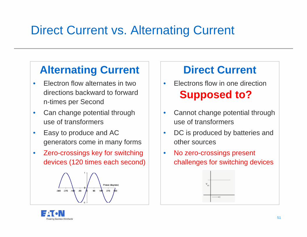
Direct Current vs. Alternating Current
Alternating Current Direct Currentg• Electron flow alternates in two
directions backward to forward n-times per Second
• Electrons flow in one direction
Supposed to?n times per Second
• Can change potential through use of transformers
• Easy to produce and AC
• Cannot change potential through use of transformers
• DC is produced by batteries andEasy to produce and AC generators come in many forms
• Zero-crossings key for switching devices (120 times each second)
DC is produced by batteries and other sources
• No zero-crossings present challenges for switching devicesdevices (120 times each second) challenges for switching devices
51 51

Direct Current vs. Alternating Current
Safety Discussion• If you touch . . . EITHER TYPE CAN KILL YOU• Work de-energized
Safety equipment will have an AC or DC rating: check it• Safety equipment will have an AC or DC rating: check it
Example: It is important to select gloves & other safety equipment rated for their p g y q pparticular applications.
CLASS TEST AC VOLTS USE AC VOLTS USE DC VOLTS LABEL COLOR
00 2,500 500 750 Beige....
0 5,000 1,000 1,500 Red
1 10,000 7,500 11,250 White
2 20,000 17,000 25,500 Yellow
3 30 000 26 500 39 750 Green
52 52
3 30,000 26,500 39,750 Green
4 40,000 36,000 54,000 Orange
http://www.supplylinedirect.com/tech_info/article.asp?ARTICLE_ID=21&F_CATEGORY_ID=3
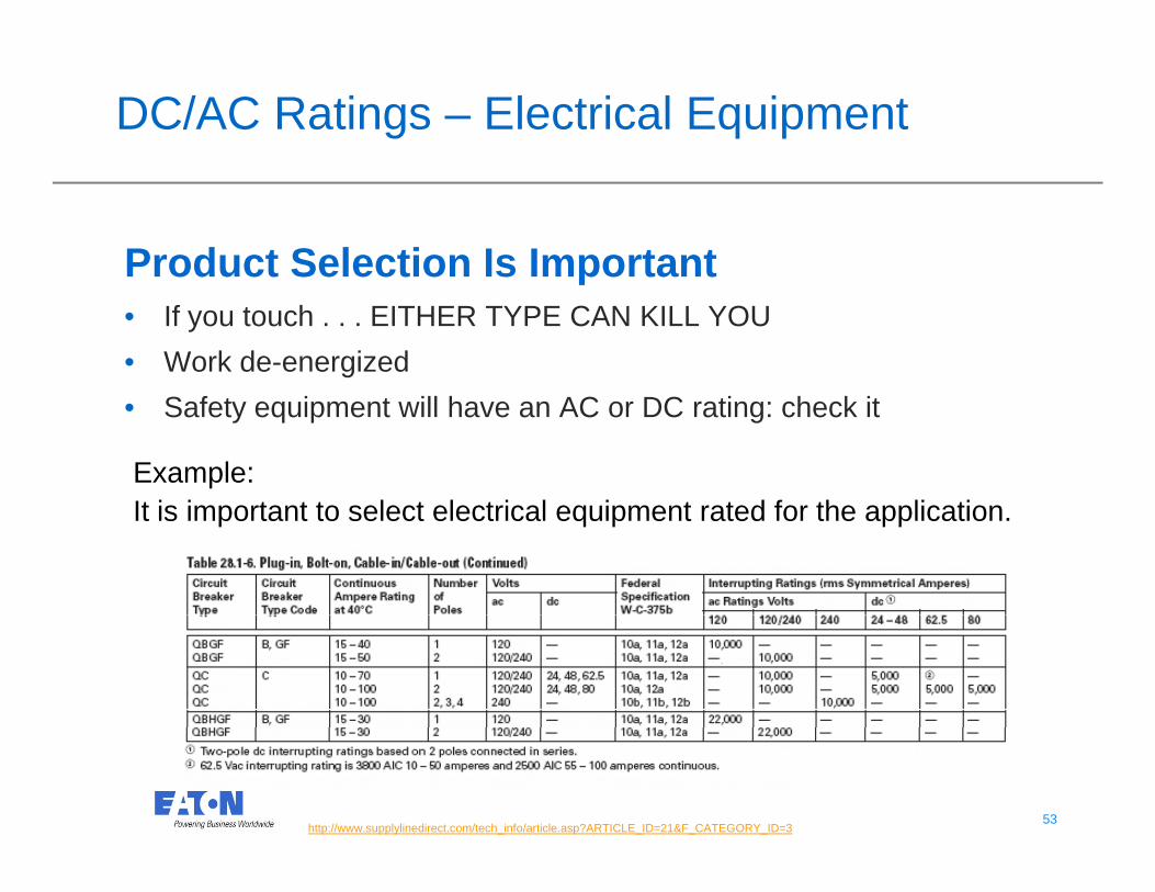
DC/AC Ratings – Electrical Equipment
Product Selection Is Importantp• If you touch . . . EITHER TYPE CAN KILL YOU• Work de-energized• Safety equipment will have an AC or DC rating: check it
Example: It i i t t t l t l t i l i t t d f th li tiIt is important to select electrical equipment rated for the application.
....
53 53http://www.supplylinedirect.com/tech_info/article.asp?ARTICLE_ID=21&F_CATEGORY_ID=3

Read the Label
54 54
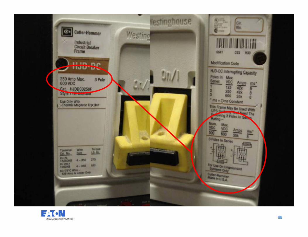
DC Breaker Image
55 55

DC Arc Interruption Techniques
Multiple Poles Magnetic Fields• Multiple Poles Break
Current• Works for currents
• Single Pole Breaks Current
• Normally Works forWorks for currents flowing in both directions
• Un-used poles
Normally Works for currents flowing in one direction (Read Instructions)
• No un used poles• One circuit per device • No un-used poles • Multiple circuits per
device
Ensure You Read The Manufacturer’s Instructions & Understand The Limitations
56 56
Understand The Limitations

Equipment Identification
110.3 (B) Identification of Equipment
Listed and labeled equipment must be installed in Listed and labeled equipment must be installed in accordance with any instructions included in the listing or labeling.
690.4(D) Inverters, Motor Generators, Photovoltaic Modules, Source Circuit Combiners, Charge C t ll h ll b id tifi d d li t d f th Controllers, shall be identified and listed for the application.
Testing agency will label equipment and that label must be
57 57
maintained.
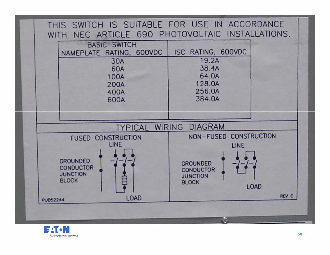
58 58

Identified and Listed
• NEC Part I. 690. 4(D) EquipmentAll i t i t d d f i h t lt i• All equipment intended for use in photovoltaic power systems shall be identified and listed for the application. Module, Inverters, Combiners, and Disconnects., , ,
59 59
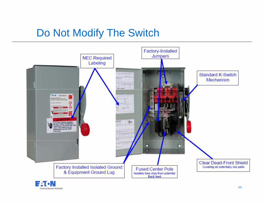
Do Not Modify The Switchy
60 60

Arc Flash Labeling Also Required for DC
110.16 Arc Flash ProtectionProtectionCompliance:Other than dwelling occupancies.When equipment is likely to require examination, adjusting, servicing or maintenance whileservicing, or maintenance while energized.Note: Commercial only
61 61
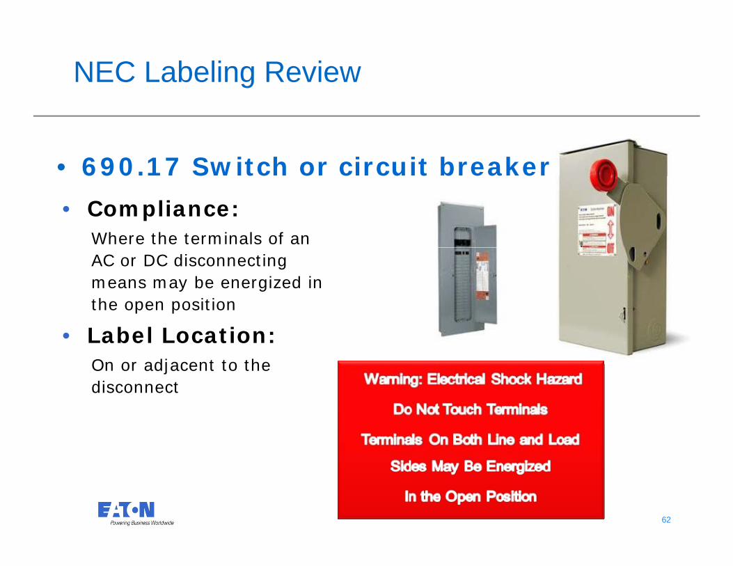
NEC Labeling Review
• 690.17 Switch or circuit breaker
• Compliance:Where the terminals of an AC or DC disconnecting means may be energized in the open position
• Label Location:On or adjacent to the disconnectdisconnect
62 62

NEC Labeling Review
690.53 Direct Current Photovoltaic Power Source• Compliance: Needs to be installed on all DC Photovoltaic power
source disconnecting means
63 63

NEC Labeling Review
Compliance:
690.64(B)(4)Point of Connection Marking
All disconnecting means shall be marked to indicate it purpose
Example:
•Main Service Disconnect
•PV System Disconnect 690.14 C
(needs label even if evident)
64 64
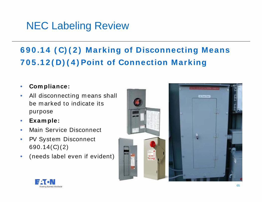
NEC Labeling Review
690.14 (C)(2) Marking of Disconnecting Means
705 12(D)(4)Point of Connection Marking 705.12(D)(4)Point of Connection Marking
• Compliance:Compliance:
• All disconnecting means shall be marked to indicate its purpose p p
• Example:
• Main Service Disconnect
• PV System Disconnect • PV System Disconnect 690.14(C)(2)
• (needs label even if evident)
65 65

66 66
67 67

68 68
69 69
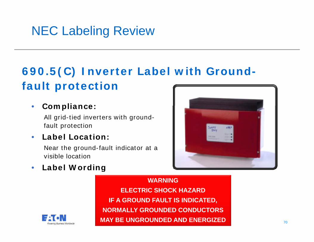
NEC Labeling Review
690.5(C) Inverter Label with Ground-( )fault protection
• Compliance:• Compliance:All grid-tied inverters with ground-fault protection
• Label Location:• Label Location:Near the ground-fault indicator at a visible location
• Label Wording• Label Wording
WARNINGELECTRIC SHOCK HAZARD
70 70
IF A GROUND FAULT IS INDICATED,NORMALLY GROUNDED CONDUCTORS
MAY BE UNGROUNDED AND ENERGIZED
71 71

72 72

Reverse Feed Situations
• Not All Circuit Breakers Can Be Reverse fed• If Marked LINE/LOAD – DO NOT REVERSE
73 73
FEED

Connections / Terminations
• Tapping of Bus Bar• If Not Listed for Field Tapping – A Field Evaluation May Be
Warranted – Your Label Could be at RiskP lb d d d df t it hb d t Li t d t• Panelboards and deadfront switchboards are not Listed to have busbars tapped unless existing holes are marked with the word “Tap” adjacent to themthe word Tap adjacent to them
• Other holes in busbar not marked with “Tap” are intended for overcurrent devices or other devices
• Watch for product markings and read installation instructions
74 74

Connections / Terminations
75 75
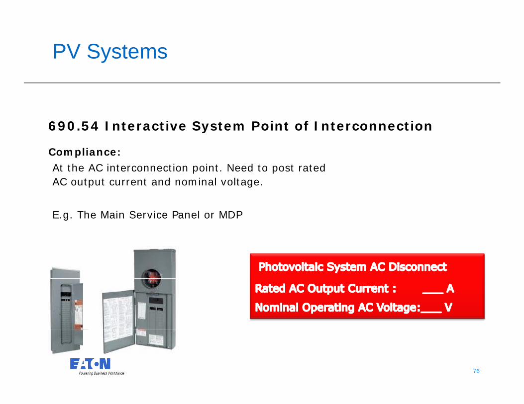
PV Systems
690 54 Interactive System Point of Interconnection690.54 Interactive System Point of Interconnection
Compliance:At the AC interconnection point. Need to post rated AC output current and nominal voltage.
E.g. The Main Service Panel or MDP
76 76

PV Systems
690.64(B)(7) Marking of Overcurrent Devices
Note: 2011 NEC Moved to 705 12(D)(7)Note: 2011 NEC Moved to 705.12(D)(7)
Compliance:Where a panel’s bus bar rating is exceeded by 20% per 690.64(B)The breaker at the AC interconnection point shall be marked be marked. Label Location:Where the AC interconnection overcurrent protection device is located.
77 77

This is a photographic template – yourphotograph should fit precisely within this rectangle.
Questions?Q
© 2010 Eaton Corporation. All rights reserved.