equiwedge edward valves gate valves - flowserve · pdf file1 to 24 gate valve figure numbers...
TRANSCRIPT
Edward ValvesMaintenance Manual for Edward
Equiwedge™ Gate ValvesV-378 R1

2
Flow Control Division
Edward ValvesTable of Contents
Introduction and Scope .........................3
Gate Valve Figure Numbers...................3
Description of Equiwedge Gate Valve Types...............................4
Type I..................................................4
Type II ..............................................4-5
Type III ................................................5
Type IV................................................5
Type V.................................................5
Service Problems ..................................6Packing Chamber Leak.......................6Packing Recommendations..................6Pressure Seal Gasket Leak ..................7Pressure Seal Leak .............................7Gate and Seat Leakage......................8Body or Bonnet Wall Leak ..................8Lubrication ........................................8
Repair Procedures.................................9Valve Body Repairs.– BodyBore Gasket Seal Area Repairs .........9
Body Wall Repairs ...........................10Body Guide Repairs.........................10Seat Repairs....................................10Gate Repairs...................................11Bonnet Repairs ................................11Backseat .........................................11Porosity in Bonnet ............................12Stem Repairs ...................................12Field Repair Equipment.....................12
Disassembly Procedure for Equiwedge Gate Valves....................13
Disassembly Procedure for Bonnet Types,Area 3
Type I .............................................14Type II ............................................15Type III ...........................................16Type IV & V ....................................17
Reassembly Procedures for EquiwedgeGate Valves ....................................18
Exploded View ...................................19
Reassembly Instructions........................20Handwheel Actuated Valves..............20Tapered Roller Bearing
Preload Instructions ........................21Reassembly Instructions for
Valves with Composite Pressure Seal Gaskets Only .........................23
Type I Reassembly............................24Type II Reassembly...........................25Type III Reassembly ..........................26Type IV & V Reassembly ...................26
Appendix AProcedure for Removing Manual
& Electric Actuators ...................28-29
Appendix BValve Tools Available for Rental .........30
Terms and Conditions..........................31
Contact Information ............................32
TABLES
Table 1 Gland Bolt Torques.................7
Table 2 Bonnet/Cover Bolt/Nut Pull-up Torques.................7
Table 3 Welding Rod Recommendations ................22
Table 4 Dimensions for Bearing Preload Washer.......22
Table 5 Bearing Retainer Preload Torque ....................22
Table 5A ..........................................22
Table 6 Bearing Retainer Final Torque ........................22
Table 6A ..........................................22
Table 7 Composite Gasket Bonnet/Cover Bolt/Nut Pull-Up Torques ....................23

3
Flow Control Division
Edward ValvesIntroduction and Scope
IntroductionThis manual has been prepared to serve asa guide for maintenance of EdwardEquiwedge gate valves, all of whichfeature the pressure seal bonnet jointconstruction. Although rigid metallurgical,non-destructive examination, physical andvisual inspection is standard procedure forEdward Valves products, it is inevitablethat some valves, after a period of time,will require repairs. This manual will assistyou in restoring the valve to good workingcondition with a minimum of time andexpense.
ScopeBefore starting any repairs, it will behelpful to have some understanding of thevalve’s physical construction. Consequently,the five basic types of pressure seal con-struction are discussed and illustrated first.All Equiwedge gate valves employ one ofthese five basic types.The next major section of this manualdiscusses the more common serviceproblems, and explains the reason forcertain failures. The reason for the problemshould be understood before work is actu-ally started.Then, the procedure to be followed in mak-ing the repair is explained. This sectionincludes normal valve maintenance as wellas major valve repairs. Field repair equip-ment available from Edward Valves isdescribed and illustrated. Valve lubrication
and welding rod recommendations arealso included. These procedures should beadequate for almost any Equiwedge gatevalve repair or maintenance problem thatmay arise.Following is a section describing thedisassembly procedure for the variousvalve components; for example, manualhandwheel, manual geared actuators orelectric actuators, valve yokes, and the fivebasic bonnet types. It is very important thatthis manual be studied before anydisassembly work is done to avoid need-less work and loss of time by selecting theimproper procedures.The last sections include reassembly instruc-tions and available maintenance equip-ment and information on the various typesof actuators, both manual and electrical.
Figure No. Class Pressure Seal Type Size1611-1611Y 600 I & II 21⁄2 to 28
1711Y Special Class 600 I & II 21⁄2 to 281911-1911Y 900 III, IV, & V 21⁄2 to 28
14311Y Special Class 900 III, IV, & V 21⁄2 to 2811511-11511Y 1500 III, IV, & V 21⁄2 to 24
12011Y Special Class 1500 III, IV, & V 21⁄2 to 2412511-12511Y 2500 III, IV, & V 21⁄2 to 24
14411Y Special Class 2500 III, IV, & V 21⁄2 to 24
Gate Valve Figure Numbers Described in this Manual

4
Flow Control Division
Edward ValvesDescription of Equiwedge Gate Valve Types
Type I is a flanged yoke design with aseparate gasket retainer ring, both ofwhich are held to the body by capscrews. The bonnet retainer is screwedonto the bonnet and cap screws arescrewed down on top of the body to forcethe bonnet into contact with the gasket.See illustration No. 1.Type II is a flanged yoke design with orwithout a separate bonnet retainer ring,both of which are held on the body bycap screws or studs and nuts. The bonnetis pulled up into contact with the gasketwith studs and hex nuts. See illustrationsNos. 2A and 2B, pgs. 4 and 5.
Type III is a wishbone yoke design boltedto the body. It has a segmental retainingring, spacer ring and a screwed onbonnet retainer equipped with push downbolts to pull the bonnet up into contactwith the gasket. See illustration No. 3,pg. 5. Type IV is a wishbone yoke designed bolt-ed to the body. It has a segmentalretaining ring, spacer ring and separatebonnet retainer with pull up studs screwedinto the bonnet to contact the gasket. Seeillustration No.4, pg. 5.
Type V has a yoke lock ring connection tothe body with a segmented ring, gasketretainer and a separate bonnet retainerwith studs screwed into the bonnet to pullup the bonnet against the gasket. Seeillustration No. 5, pg. 5.
Illustration No. 1 Illustration No. 2ASize 2-1/2 & 3 - Figure 1611 and 1611Y Size 4” -Figure 1611 and 1611YSize 2-1/2 & 3 - Figure 1711Y Size 4” - Figure 1711Y
Valve Type I Valve Type IIA

5
Flow Control Division
Edward ValvesDescription of Equiwedge Gate Valve Types (cont.)
Illustration No. 2BSize 6 - 28 - Figure 1611 and 1611YSize 6 - 28 - Figure 1711YNOTE: Size 6 and 8 valves are wishbone yoke design with flange.
Valve Type IIB
Illustration No. 4Size 4 - 8 - Figure 1911-1911Y-14311YSize 4 - 8 - Figure 11511-11511Y-12011YSize 4 - 8 - Figure 12511-12511Y-14411Y
Valve Type IV
Illustration No. 3Size 2-1/2 - 3 - Figure 1911-1911Y-14311YSize 2-1/2 - 3 - Figure 11511-11511Y-12011YSize 2-1/2 - 3 - Figure 12511-12511Y-14411Y
Valve Type III
Illustration No. 5Size 10 - 28 - Figure 1911-1911Y-14311YSize 10 - 24 - Figure 11511-11511Y-12011YSize 10 - 24 - Figure 12511-12511Y-14411Y
Valve Type V
6
Flow Control Division
Edward ValvesService Problems
Packing Chamber LeakWhere moisture appears or actual drippingoccurs at the packing chamber around thestem, gland or gland flange which cannotbe eliminated by re-torquing the gland boltthe following points should be considered.
1. The packing may have become hard.Replace the packing.
2. Gland travel has been fully taken up.Repack with new packing.
3. The wrong packing is being used. See packing recommendations shownon this page.
4. A stem should be replaced when ithas become deeply scratched,burred, or otherwise mutilated fromcareless handling, or where the stemhas worn, tapered or has been bent.
5. The gaps in the rings of split packinghave not been staggered around thestem. They should be inserted in thismanner.
6. The packing gland may be bindingagainst the packing chamber or stemand does not compress the packingproperly. Make certain the gland fitsthe packing chamber and is tight-ened down equally on each side.
Packing RecommendationsEdward valves are packed with all-purposewith packing sets. This is a combination ofpacking using braided rings at the top andbottom in the packing chamber and flexi-ble graphite packing in the center section.Packing gland should be tightened downenough to prevent leakage but not enoughto develop excessive operating torque.When the gland has advanced approxi-mately half way into the packing chamber,it is recommended that additional packingrings be added. To obtain best results, the stem should be thoroughly cleaned.Replacement packing should be the sameas that originally furnished.We recommend that replacement packingbe purchased from Edward Valves toassure packing with the proper density andcorrosion inhibitors is always used.
IMPORTANT:Long service life from modern graphiticpacking requires that adequate preloadsbe applied when repacking.
1. All parts should be clean and notscored or pitted, especially the stem.
2. The valve internal parts and bonnetshould be assembled prior toinstalling the packing.
3. Position split packing rings with theends of adjacent rings rotated 90°.
4. Install in the following sequence:Bottom Ring – Braided RingCenter Rings – Die formed
expanded graphiteTop Ring – Braided Ring
5. Clean and lubricate the gland eye-bolts.
6. Carefully seat each individual pack-ing ring before adding the next ring.
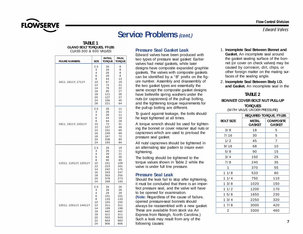
7. Apply the recommended torque tothe gland nuts evenly without cockingthe gland. See Table 1, pg. 7, forrecommended torques.
8. Tighten the nuts to the initial valuesshown, then loosen and re-tighten tothe final torque.
9. Stroke the valve, then re-check thegland nut torques.
Note: The torque values given are forsealing full rated pressure. For line pres-sures less than the full CWP rating of thevalve, the final torques may be reduced bythe ratio of Pactual/CWP down to a mini-mum of Pactual = 1500 psig. This willreduce packing drag and extend packinglife.
Flow Control Division
Edward ValvesService Problems (cont.)
Pressure Seal Gasket LeakEdward valves have been produced withtwo types of pressure seal gasket: Earliervalves had metal gaskets, while laterdesigns have composite expanded graphitegaskets. The valves with composite gasketscan be identified by a “B” prefix on the fig-ure number. Assembly and disassembly ofthe two gasket types are essentially thesame except the composite gasket designshave belleville spring washers under thenuts (or capscrews) of the pull-up bolting,and the tightening torque requirements forthe pull-up bolting are different.To guard against leakage, the bolts shouldhe kept tightened at all times.A torque wrench should be used for tighten-ing the bonnet or cover retainer stud nuts orcapscrews which are used to pre-load thepressure seal gasket.All nuts/capscrews should be tightened inan alternating star pattern to insure eventightening.The bolting should be tightened to thetorque values shown in Table 2 while thevalve is under full line pressure.
Pressure Seal LeakShould the leak fail to stop after tightening,it must be concluded that there is an imper-fect pressure seal, and the valve will haveto be opened for examination. (Note: Regardless of the cause of failure,opened pressure-seal bonnets shouldalways be reassembled with a new gasket.These are available from stock via AirExpress from Raleigh, North Carolina.)Such a leak may result from any of thefollowing causes:
1. Incomplete Seal Between Bonnet andGasket. An incomplete seal aroundthe gasket seating surface of the bon-net (or cover on check valves) may becaused by corrosion, dirt, chips, orother foreign matter on the mating sur-faces of the sealing angle.
2. Incomplete Seal Between Body I.D.and Gasket. An incomplete seal in the
INITIAL FINALFIGURE NUMBERS SIZE TORQUE TORQUE
2.5 26 83 26 84 26 86 29 88 44 13
1611, 1611Y, 1711Y 10 67 1912 72 2114 76 2216 95 2718 121 3520 127 3724 156 4528 221 64
2.5 26 113 26 114 26 116 44 198 64 28
1911, 1911Y, 14311Y 10 72 3112 107 4614 151 6516 159 6918 167 7220 208 9024 193 84
2.5 26 193 26 114 29 216 48 358 90 65
11511, 11511Y, 12011Y 10 151 10912 223 16114 242 17516 343 24718 353 25520 378 27324 268 193
2.5 26 263 26 264 29 296 101 1018 133 133
10 155 15512511, 12511Y, 14411Y 12 311 311
14 199 19916 442 44218 311 31120 503 50322 663 66324 806 806
TABLE 1GLAND BOLT TORQUES, FT-LBS
CLASS 300 & 600 VALVES
TABLE 2BONNET/COVER BOLT/NUT PULL-UP
TORQUES (WITH VALVE UNDER PRESSURE)
REQUIRED TORQUE, FT-LBSBOLT SIZE METAL COMPOSITE
GASKET GASKET3/8 18 5
7/16 30 51/2 45 7
9/16 68 105/8 90 153/4 150 257/8 240 351 370 55
1 1/8 533 801 1/4 750 1101 3/8 1020 1501 1/2 1200 1701 5/8 1650 2301 3/4 2250 3201 7/8 3000 420
2 3300 460
7
8
Flow Control Division
Edward ValvesService Problems (cont.)
area of the gasket and body I.D. contactmay be caused by surface imperfectionsin the body wall in the form of pin holes,extended cracks, or indentations wherethe metal has failed sometime after valveinstallation and use. Such imperfectionsmay be surface indications deeper flawsin the body casting which may cause aby-pass around the pressure seal.
Gate and Seat LeakageA leak existing at the seat and gate of aproperly closed valve might be indicatedby one of the following: a definite pressureloss in the high pressure side of the valve;continued flow through an inspection drainon the low pressure side; or, in hot lines, adownstream pipe that remains hot beyondthe usual length of time and conductivityrange. First, try opening the valve slightlyto flush any foreign material from the seat-ing surfaces and then fully close the valve.If this doesn’t stop the leakage, then one ormore of the following may be the cause: 1. Foreign material has been imbedded
into the seating surfaces preventing aseal.
2. Foreign material has scratched or cutthe seating surface.
3. An obstruction such as a tool or other
foreign material has been lodged acrossor between the seats and preventing thegate from closing.
4. The valve seat has been steam or watercut by not fully closing the valve duringa previous operation.
If the valve cannot be isolated andrepaired as soon as possible, schedule thework to be done at the next outage.
Body or Bonnet Wall LeakThis is a leak through the pressure contain-ing parts of the valve. A leak occurringthrough the bonnet should be readilydetectable because of the lack of insula-tion. On the body, because of the heavyinsulation, a small leak may go unnoticedfor a time on a hot line because the pipingevaporates the leakage.
LubricationIn order to obtain long service life andmaximum reliability, valves require per-iodic lubrication of the bearings and stemthreads the same as for any machinerywith rotating parts.
All handwheel actuated Equiwedge gatevalves are equipped with low friction bear-ings, needle bearings in the smaller sizesand tapered roller bearings in the largersizes. These valves have a lube fitting forconvenient relubrication. Both the stemthreads and the bearings can be relubedthrough this fitting. In addition, it is advis-able to clean the stem first while in theopen position and apply fresh grease tothe threads, then repeat while in the closedposition.For valves that are operated infrequently,relubrication at least once a year is recom-mended. The recommended lubricant forboth bearings and stem threads is RyconEP 2, manufactured by the American OilCompany. This is an extreme pressure,temperature lubricant of high quality. Useof other lubricants should be avoided.For valves that are operated frequently, thelubricant should be replenished at both thebearings and stem threads every threemonths or at shorter intervals dependingon the severity of the service.
9
Flow Control Division
Edward Valves
VALVE BODY REPAIRS
Body Bore Gasket Seal Area Repair (Valves with metal gasket only)Class 600 Equiwedge gate valves havethe seal area for the pressure seal justbelow the top of the body bore. The sealsurface is inlaid with 18-8 stainless steelon all valves size 16 and larger.Class 900 and higher Equiwedge gatevalves have the seal area just below thegasket retainer groove. The seal surface isinlaid with 18-8 stainless steel on all valvesin these pressure classes.The seal area, whether inlaid or not, mustbe smooth, round and without any appre-ciable taper. Upon normal disassembly ofthe valve the gasket may leave some verti-cal score marks when withdrawn.If the depth of defects are .010” or less,the seal area can be honed using aportable Sunnen Hone. This device isadjustable for different bore sizes and canbe operated by one man using a portableelectric drill of 1/2” to 3/4” capacity.When the defects are greater than .010”,welding will be required to cut down therepair time.First make visual inspection all around thisarea, noting, if possible, where flaws mayoccur. Next wash the area with a suitablesolvent, drying with clean rags and, if nec-essary, polishing with a fine grade ofemery cloth to remove any undesirablescale or foreign matter which may be beendeposited on the area suspected of havingflaws. Use a dye penetrant test if cracksare suspected.
Where it is necessary to repair the bodyinlay by welding, note the following:
1. Prior to any cutting or welding oper-ations being performed on the valve,it is necessary that adequate seatjoint protection be provided andsome means of insurance againstgetting chips, weld spatter or otherforeign matter into the pipe line ifthe valve is permanently mounted. Around piece of sheet metal placed inthe bore down to the shoulder abovethe guide grooves and taped inplace will protect the guide surfacesand seats.
2. Chip out the defective area in thebody, being careful to remove theaffected portion to its end, inside thecasting, and to thoroughly clean itaway.
3. With a small hand grinder, grind thechipped area smooth.
4. Preheat an area large enougharound the imperfection so that dur-ing the entire welding operation heatwill be retained at approximately400 degrees Fahrenheit.
5. Use a stainless steel inlay selectedfrom either 18-8 stainless steel rod,Harstain 18-8, Stainweld “K” 18-3,Stainweld 18-8 or equivalent.
6. Lay the weld in thin, even layers,peening each layer before proceed-ing with the next, and being carefulto maintain a temperature above400 degrees Fahrenheit in the areabeing repaired. Peening the bead
actually stretches it and counteractsits tendency to contract and shrink asit cools. The last layer of weld mustoverlap onto the sound metal toinsure a weld without an undercut atthe edges. The overlapping shouldbe done along this edge by using awelding rod of 1/8” maximum diam-eter. The last layer should bring theheight of the welded area up to1/16” above the original surface, aschecked with a straight edge alongthe body bore. For this type of weld repair, it is rec-ommended that the last layer bepounded while still hot with the flatface of the hammer. Thermal stressrelieving is not recommended. With a hand grinder, rough grindthe welded surface to within about.010” of the finished surface. A sim-ple template cut from thin sheetmetal and having the same arc asthe body bore diameter, and straightedge laid along the body bore canbe used as a guide. A final cut thencan be made, using a fixture similarto the one shown in Illustration No.9, pg. 15. Final finishing can bedone with the adjustable Sunnenhone described on this page.After removing all the dirt, chips,slag, spatter, and grinding dust fromthe body, the bore should be pol-ished with fine emery cloth and thenthoroughly cleaned before reassem-bly of the valve.
Repair Procedures
10
Flow Control Division
Edward Valves
It is best that a new pressure-sealgasket be used upon reassembly.
Body Wall RepairsThere are five basic steps in repairing acasting defect:1. Cut out to sound metal. Attempting to
weld over the defect will only leave anotch that may re-introduce the defect.Cutting may be done by chipping,grinding or flame gouging. The amountof metal removed should be held to aminimum to avoid distortion during sub-sequent welding.
2. Preheat, using the minimum temperaturespecified by the material specificationand/or the design code. Use at least400F on WC9 or C5 material, 300Fon WC6. Although cast carbon steelssuch as WCB or WCC do not requirepreheat, it may be advantageous toremove any moisture or other contami-nants from the area to be welded. Thismay also identify any leak paths. Thereare also disadvantages to preheat,especially localized preheat, that mustbe considered when working in areasof the casting with finish machineddimensions. Distortion may result inmore damaging problems than thoseconcerns created by the original defect.Lower preheats and the control of inter-pass temperature are two methods usedto minimize distortion.
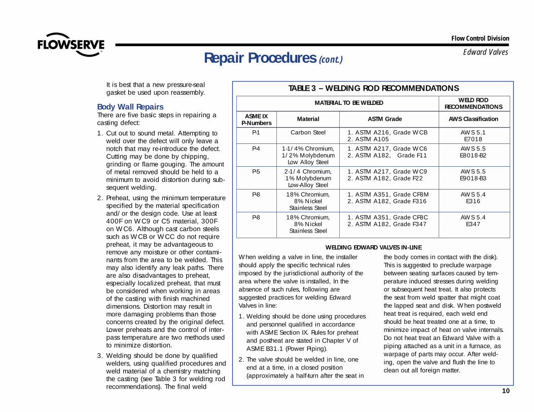
3. Welding should be done by qualifiedwelders, using qualified procedures andweld material of a chemistry matchingthe casting (see Table 3 for welding rodrecommendations). The final weld
TABLE 3 – WELDING ROD RECOMMENDATIONS
MATERIAL TO BE WELDED WELD RODRECOMMENDATIONS
ASME IX Material ASTM Grade AWS ClassificationP-Numbers
P-1 Carbon Steel 1. ASTM A216, Grade WCB AWS 5.12. ASTM A105 E7018
P-4 1-1/4% Chromium, 1. ASTM A217, Grade WC6 AWS 5.51/2% Molybdenum 2. ASTM A182, Grade F11 E8018-B2
Low Alloy SteelP-5 2-1/4 Chromium, 1. ASTM A217, Grade WC9 AWS 5.5
1% Molybdenum 2. ASTM A182, Grade F22 E9018-B3Low-Alloy Steel
P-8 18% Chromium, 1. ASTM A351, Grade CF8M AWS 5.48% Nickel 2. ASTM A182, Grade F316 E316
Stainless SteelP-8 18% Chromium, 1. ASTM A351, Grade CF8C AWS 5.4
8% Nickel 2. ASTM A182, Grade F347 E347Stainless Steel
Repair Procedures (cont.)
WELDING EDWARD VALVES IN-LINE
When welding a valve in line, the installershould apply the specific technical rulesimposed by the jurisdictional authority of thearea where the valve is installed, In theabsence of such rules, following aresuggested practices for welding EdwardValves in line:
1. Welding should be done using proceduresand personnel qualified in accordancewith ASME Section IX. Rules for preheatand postheat are stated in Chapter V ofASME B31.1 (Power Piping).
2. The valve should be welded in line, oneend at a time, in a closed position(approximately a half-turn after the seat in
the body comes in contact with the disk).This is suggested to preclude warpagebetween seating surfaces caused by tem-perature induced stresses during weldingor subsequent heat treat. It also protectsthe seat from weld spatter that might coatthe lapped seat and disk. When postweldheat treat is required, each weld endshould be heat treated one at a time, tominimize impact of heat on valve internals.Do not heat treat an Edward Valve with apiping attached as a unit in a furnace, aswarpage of parts may occur. After weld-ing, open the valve and flush the line toclean out all foreign matter.
11
Flow Control Division
Edward Valves
should be blended into the contour ofthe casting.
4. Stress relieving is generally recommend-ed. Decisions to not stress relieve shouldfactor in piping code rules. The temper-atures must be based on material speci-fication and piping code recommenda-tions. Again, since temperatures aremuch higher than those experienced inwelding, there are also disadvantagesthat must be considered. Distortion mayresult in more damaging problems.Lower temperature postweld heat treat-ment is sometimes an option for carbonsteels.
5. The final weld should receive any need-ed nondestructive testing. This shouldinclude a visual examination and liquidpenetrant or magnetic particle examina-tion. Some major weld repairs couldeven mandate radiography to ensure asound weld.
Body Guide RepairsThe body guide grooves guide the gatethrough about 95% of the valve stroke andallow only 5% of the valve stroke to thrustagainst the seating surfaces. It is importantthat the side faces of the groove be smoothand free of gouges and burrs. A flat filecan be used to remove any burrs andraised edges.
Seat RepairsThe seats in a gate valve may requirerepair when the seating surfaces allowfluid to pass. This may be due to erosionof the surfaces caused by not closing thevalve tightly or seating on foreign material.Verification of such conditions may beobtained by a seat blueing test or by closevisual examination.To correct these conditions seat refinishingwill be necessary. A Dexter gate valverefinishing fixture will speed up repairs.See Appendix B for a discussion on use ofthe Dexter equipment.
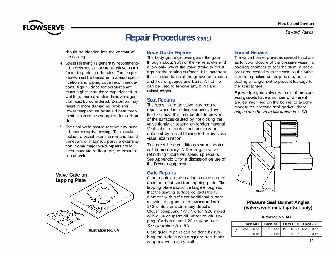
Gate RepairsGate repairs to the seating surface can bedone on a flat cast iron lapping plate. Thelapping plate should be large enough sothat the seating surface contacts the fulldiameter with sufficient additional surfaceallowing the gate to be pushed at least1/3 of its diameter in any direction.Clover compound “A”, Norton 320 mixedwith olive or sperm oil, or for rough lap-ping, Carborundum H20 may be used.See illustration No. 6A.Gate guide repairs can be done by rub-bing the surface with a square steel blockwrapped with emery cloth.
Bonnet RepairsThe valve bonnet provides several functionsas follows: closure of the pressure vessel, apacking chamber to seal the stem, a back-seat area sealed with the stem so the valvecan be repacked under pressure, and asealing arrangement to prevent leakage tothe atmosphere.Equiwedge gate valves with metal pressureseal gaskets have a number of differentangles machined on the bonnet to accom-modate the pressure seal gasket. Theseangles are shown in illustration No. 6B.
Repair Procedures (cont.)
Illustration No. 6A
Valve Gate on Lapping Plate A°
±0.25° 30°
Pressure Seal Bonnet Angles(Valves with metal gasket only)
Illustration No. 6B
Class 600 Class 900 Class 1500 Class 2500
A 25° +0.5° 35° +0.5° 35° +0.5° 45° +0.5°- 0.0° - 0.0° - 0.0° - 0.0°
12
Flow Control Division
Edward ValvesRepair Procedures (cont.)
If the gasket sealing surface of the bonnethas been damaged by corrosion, erosionor careless handling, this surface can bemachined in a lathe. Chuck the bonnet,indicate true the large diameter and thebottom face before cutting the angle. Theangle should be generated using a highspeed or carbide cutting tool. Remove aslittle stock as possible to clean up. Thesurface finish should be held to 63 microinch (1.6 micrometer) or better.
BackseatThe backseating surface is inlaid withhardfacing. Any machining on this surfacemust be done with carbide tools. Theincluded angle of the backseat is 60° andthe tolerance on the half angle is ± 0.25°.The surface finish should be held to 63micro inch (1.6 micrometer) or better.Machining of this surface can be done inthe same setup as machining the pressureseal angle. Once again the angle shouldbe generated using a carbide cutting tool.
Porosity in BonnetIn most gate valve sizes and pressure class-es, the bonnet is made from a steel cast-ing. Steel castings are subject to varioustypes of defects such as shrinkage orporosity. Weld repair any defect in thebonnet wall the same as a body. If exten-sive repairs are required, remachining ofthe packing chamber, backseat, and pres-sure seal angle may be required becauseof distortion of these surfaces.
Stem RepairsThe basic function of a valve stem is toactuate the valve open or closed. Becauseit penetrates a pressure boundary, it mustprovide a diameter for the packing to sealleakage to the atmosphere and provide aseal in the fully open or backseated posi-tion so that packing may be replacedunder pressure. Stems are made of highquality martensitic stainless steel or otherstainless alloy and hardened to withstandthe high stresses. Welding is not recom-mended. Only cosmetic repairs to thepacking diameter and machining of thebackseat should be attempted. The angleon the backseat of the stem is 28° – 0.50°+ 0.25°. First contact is made at the top ofthe conical surface. Valve stems must beconcentric and free from score marks onthe packing diameter and backseat area toperform the functions listed above. Whena stem is bent or deeply scored on thepacking diameter, it should be replaced.
Field Repair EquipmentAvailable from the Edward Valves plant atRaleigh, North Carolina are some basictools for repairing valves in the field. Thisequipment was developed for customer useon a rental basis. Contact your localEdward Valves sales representative formore information. A partial list of thisequipment follows: 1. Four sizes of Dexter seat refinishing
machines complete with refinishing platesfor valve sizes 2-1/2 thru 28. (See Appendix B, pg. 30)
2. Two sizes of portable boring machinescapable of reboring the pressure sealarea in body on valves size 10 and larg-er. (See Appendix B, pg. 30)
13
Flow Control Division
Edward ValvesDisassembly Procedure for Equiwedge Gate Valves
IntroductionStep-by-step disassembly procedures aredescribed below for all types ofEquiwedge pressure seal gate valves,including those with manual and motoractuators. It is important that the following instructions be read and under-stood before any specific disassembly work is attempted.First determine the problem area.Maintenance problems can be divided intothree major areas, and the area involvedwill affect the disassembly procedure.These areas,in general, are:
Area 1 The handwheel, or a manual orelectric motor actuator.
Area 2 The yoke assembly including theyoke, yoke bushing, and bearings.
Area 3 The valve internals including thebonnet, body, pressure seal gas-ket, stem, gate, and seats.
If the problem is in Area 1, usually a man-ual or electric actuator will be involvedand not a handwheel; see Appendix A,pg. 29.
If the problem is in Area 2, it will benecessary to remove the valve actuatoronly if the valve is handwheel actuated orhas a torque-only manual or electricactuator. See procedure on pgs. 28 and29 and select the proper one.If the problem is in Area 3, two methodsare available. In method 1 the yoke andactuator assembly may be removed fromthe valve body as a unit. This saves time,but requires adequate clearance. Inmethod 2 the actuator and yoke areremoved separately.If problems are suspected to exist in anycombination of Area 1, 2 or 3, then eachof the respective procedures must befollowed.
CAUTIONAS A GENERAL REMINDER, MAKE SURE ALL THE PRESSURE IS RELIEVED, BOTH UPSTREAM AND DOWNSTREAM AND IN THECENTER CAVITY, BEFORE DISASSEMBLY WORK IS STARTED. Exceptions to this rule are noted below.1. For service In Area 1
If pressure is to be maintained in the valve, backseat to full open position. The actuator, both manual or electrical, torque-only andtorque and thrust types, may be removed. The blowout force on the stem due to pressure in the line will keep the stem on the backseat.
2. For service in Area 2If pressure is to be maintained in the valve, the yoke may be removed on Types III, IV, and V. The blowout force on the stem dueto pressure in the line will keep the stem on the backseat. UNDER NO CIRCUMSTANCES SHOULD THE YOKE BE REMOVED ONTYPES I AND II WHILE UNDER PRESSURE.
3. For service In Area 3Close the valve fully and then open 1/8” (3mm). SERVICE AREA 3 WITHOUT PRESSURE IN LINE.
14
Flow Control Division
Edward ValvesDisassembly Procedure of Bonnet Types Area 3
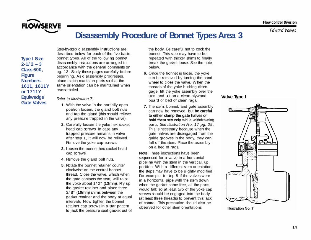
Type I Size 2-1/2 – 3Class 600,FigureNumbers1611, 1611Yor 1711YEquiwedge Gate Valves
Illustration No. 7
Valve Type I
Step-by-step disassembly instructions aredescribed below for each of the five basicbonnet types. All of the following bonnetdisassembly instructions are arranged inaccordance with the general comments onpg. 13. Study these pages carefully beforebeginning. As disassembly progresses,place match marks on parts so that thesame orientation can be maintained whenreassembled.
Refer to illustration 7.1. With the valve in the partially open
position loosen, the gland bolt nutsand tap the gland (this should relieveany pressure trapped in the valve).
2. Carefully loosen the yoke hex sockethead cap screws. In case anytrapped pressure remains in valveafter step 1, it will now be relieved.Remove the yoke cap screws.
3. Loosen the bonnet hex socket headcap screws.
4. Remove the gland bolt nuts.5. Rotate the bonnet retainer counter
clockwise on the central bonnetthread. Close the valve, which whenthe gate contacts the seat, will raisethe yoke about 1/2” (13mm). Pry upthe gasket retainer and place three3/8” (10mm) shims between thegasket retainer and the body at equalintervals. Now tighten the bonnetretainer cap screws in a star patternto jack the pressure seal gasket out of
the body. Be careful not to cock thebonnet. This step may have to berepeated with thicker shims to finallybreak the gasket loose. See the notebelow.
6. Once the bonnet is loose, the yokecan be removed by turning the hand-wheel to close the valve. When thethreads of the yoke bushing disen-gage, lift the yoke assembly over thestem and set on a clean plywoodboard or bed of clean rags.
7. The stem, bonnet, and gate assemblycan now be removed, but be carefulto either clamp the gate halves orhold them securely while withdrawingparts. See illustration No. 17 pg. 25.This is necessary because when thegate halves are disengaged from theguide grooves in the body, they canfall off the stem. Place the assemblyon a bed of rags.
Note: These instructions have beensequenced for a valve in a horizontalpipeline with the stem in the vertical, upposition. With a different stem orientation,the steps may have to be slightly modified.For example, in step 5 if the valves werein a horizontal pipe with the stem downwhen the gasket came free, all the partswould fall; so at least two of the yoke capscrews should be engaged into the body(at least three threads) to prevent this lackof control. This precaution should also beobserved for other stem orientations.

15
Flow Control Division
Edward Valves
See illustrations 8 and 9.1. With the valve in a partially open
position remove the handwheel. Thehandwheel nut is locked in positionwith a small nylock set screw. This setscrew must be loosened first beforeattempting to remove the handwheelnut. The handwheel is keyed to theyoke bushing. Remove the handwheelnut, handwheel and key and setaside.
2. Loosen the gland bolt nuts and tapthe gland loose from the packingchamber. This should relieve anypressure that may be trapped in thevalve.
3. Carefully loosen the yoke cap screwsor hex nuts. In case any trappedpressure remains in the valve afterstep 2, it will not be relieved.
Remove all yoke cap screws or hex nuts.
4. Remove the gland bolt nuts.5. Loosen the bonnet hex nuts about
3/8” (10mm) to 1/2” (13mm).6. Close the valve, which when the gate
contacts the seat, will raise the yoke.Place three or four shims 3/8”(10mm) to 1/2” (13mm) thick equallyspaced between the yoke flange andthe body. Now tighten the bonnetretainer hex nuts in a star pattern tojack the gasket out of the body. Becareful not to cock the bonnet. Thisstep may have to be repeated withthicker shims to finally break the gas-ket loose. See Note this page.
7. Once the bonnet is loose the yokecan be removed. Remove the bonnetretainer hex nuts. Sling the yokethrough the windows leaving spaceto turn the yokebushing and take upslack in a chain hoist. With a strapwrench around the top of the yokebushing, close the valve, thereby rais-ing the yoke. Keep a slight tension onthe chain hoist so that the yoke bush-ing and stem threads are not dam-aged. Also, the pull point must be inline with the stem. Raise the yoke inthis manner until the threads are dis-engaged, then lift away the yokeassembly. Set the yoke on a cleanplywood board or bed of rags.
8. Valves with stems 1.62” (41.1 mm) to2” (50.8mm) in diameter are thread-ed on the top end to accept a 1/2” –13 eye bolt and those 2” (50.8mm)in diameter or over to accept a 3/4”– 10 eye bolt. Screw the eye bolt intothe stem and attach a chain hoist. Liftthe stem, bonnet, and gate out of thevalve but be careful to clamp thegate halves securely while withdraw-ing the parts (see illustration No. 17pg. 25). This is necessary becausewhen the gate halves are disengagedfrom the body guide grooves, thehalves and spacer ring can fall offthe stem. Place the assembly on abed of rags.
Note: These instructions have beensequenced for valve in a horizontal pipe-line with the stem in the vertical, upposition. With a different stem orientation,the steps may have to be slightly modified.For example, in step 3, if the valve were ina horizontal pipeline with the stem down,when the gasket breaks free in step 6, allthe parts would fall; so, at least two of theyoke cap screws or hex nuts need to bepartially engaged into/onto the body studsto prevent this. This precaution should alsobe observed for other stem orientations.
Disassembly Procedure of Bonnet Types Area 3 (cont.)
Valve Type IIA Valve Type IIB
Illustration No. 8 Illustration No. 9
Type II Sizes 4 - 28 Class600, FigureNumbers1611,1611Y or 1711YEquiwedge Gate Valves
16
Flow Control Division
Edward Valves
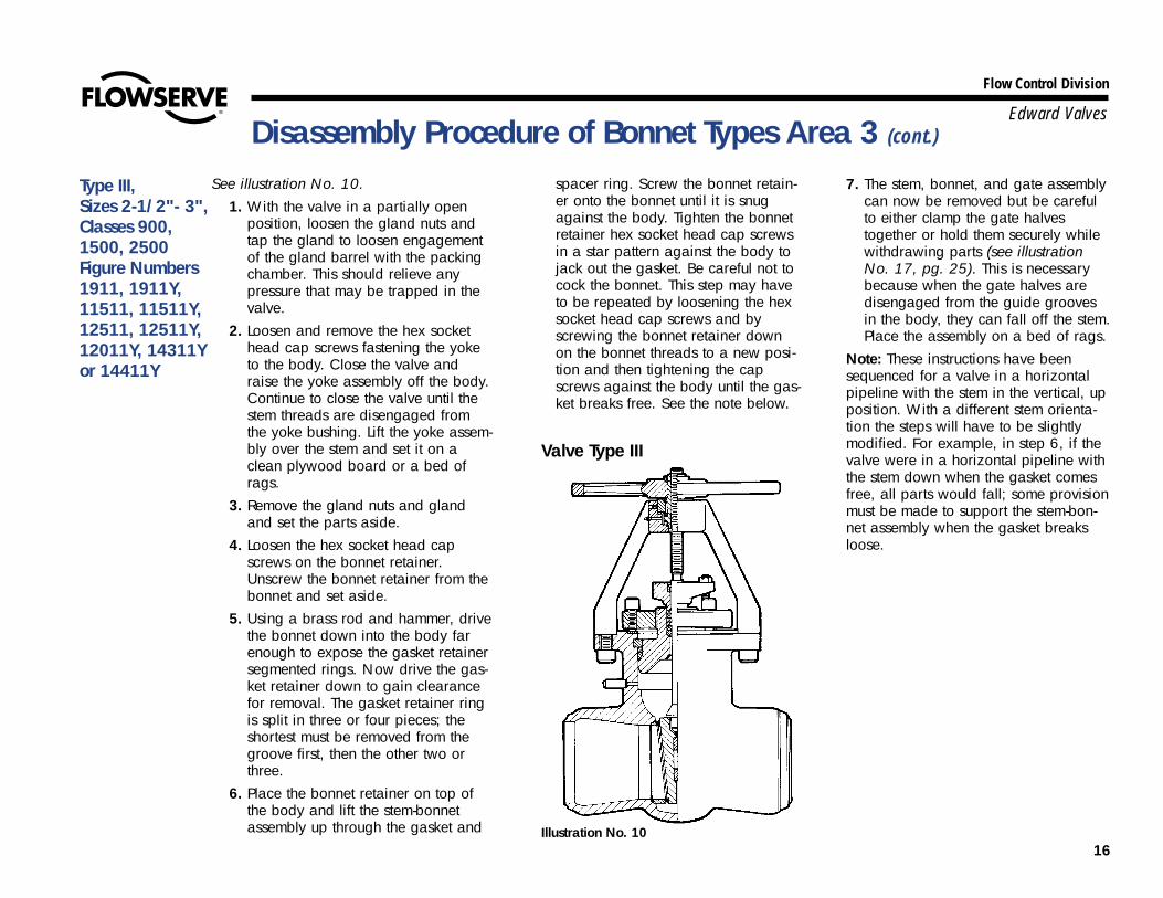
See illustration No. 10.1. With the valve in a partially open
position, loosen the gland nuts andtap the gland to loosen engagementof the gland barrel with the packingchamber. This should relieve anypressure that may be trapped in thevalve.
2. Loosen and remove the hex sockethead cap screws fastening the yoketo the body. Close the valve andraise the yoke assembly off the body.Continue to close the valve until thestem threads are disengaged fromthe yoke bushing. Lift the yoke assem-bly over the stem and set it on aclean plywood board or a bed ofrags.
3. Remove the gland nuts and glandand set the parts aside.
4. Loosen the hex socket head capscrews on the bonnet retainer.Unscrew the bonnet retainer from thebonnet and set aside.
5. Using a brass rod and hammer, drivethe bonnet down into the body farenough to expose the gasket retainersegmented rings. Now drive the gas-ket retainer down to gain clearancefor removal. The gasket retainer ringis split in three or four pieces; theshortest must be removed from thegroove first, then the other two orthree.
6. Place the bonnet retainer on top ofthe body and lift the stem-bonnetassembly up through the gasket and
spacer ring. Screw the bonnet retain-er onto the bonnet until it is snugagainst the body. Tighten the bonnetretainer hex socket head cap screwsin a star pattern against the body tojack out the gasket. Be careful not tocock the bonnet. This step may haveto be repeated by loosening the hexsocket head cap screws and byscrewing the bonnet retainer downon the bonnet threads to a new posi-tion and then tightening the capscrews against the body until the gas-ket breaks free. See the note below.
7. The stem, bonnet, and gate assemblycan now be removed but be carefulto either clamp the gate halvestogether or hold them securely whilewithdrawing parts (see illustrationNo. 17, pg. 25). This is necessarybecause when the gate halves aredisengaged from the guide groovesin the body, they can fall off the stem.Place the assembly on a bed of rags.
Note: These instructions have beensequenced for a valve in a horizontalpipeline with the stem in the vertical, upposition. With a different stem orienta-tion the steps will have to be slightlymodified. For example, in step 6, if thevalve were in a horizontal pipeline withthe stem down when the gasket comesfree, all parts would fall; some provisionmust be made to support the stem-bon-net assembly when the gasket breaksloose.
Disassembly Procedure of Bonnet Types Area 3 (cont.)
Type III, Sizes 2-1/2"- 3",Classes 900,1500, 2500 Figure Numbers1911, 1911Y,11511, 11511Y,12511, 12511Y,12011Y, 14311Yor 14411Y
Illustration No. 10
Valve Type III
17
Flow Control Division
Edward ValvesDisassembly Procedure of Bonnet Types Area 3 (cont.)
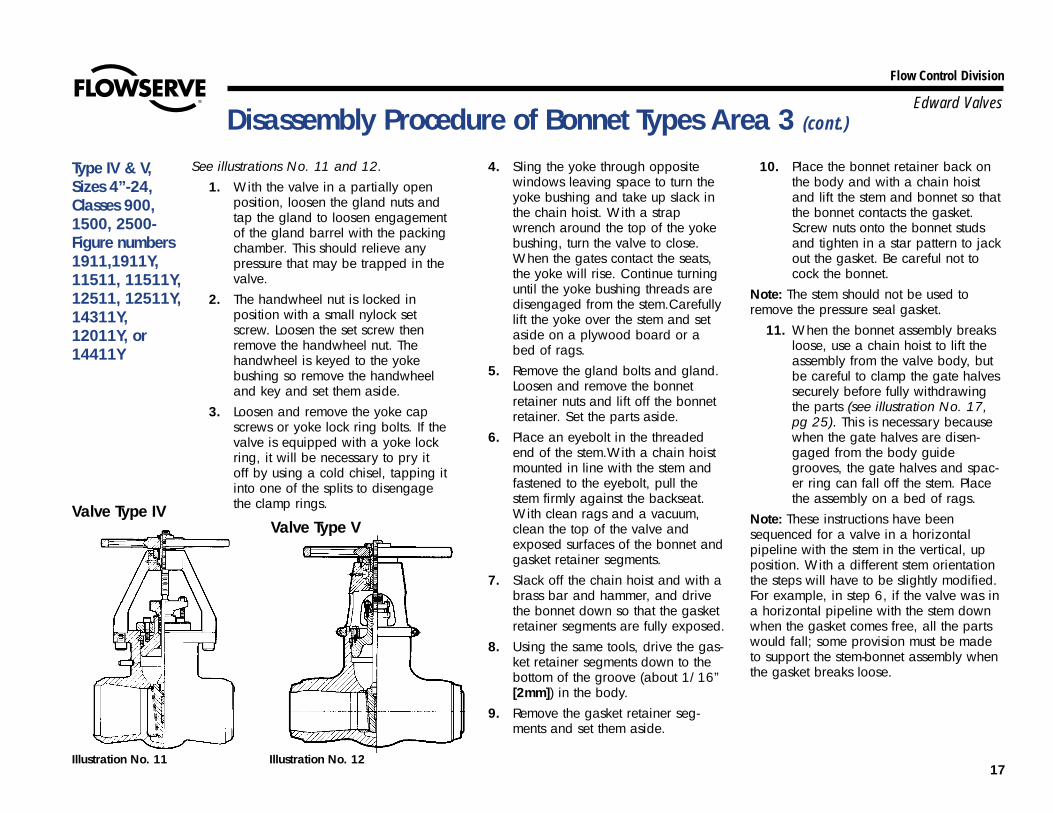
See illustrations No. 11 and 12.1. With the valve in a partially open
position, loosen the gland nuts andtap the gland to loosen engagementof the gland barrel with the packingchamber. This should relieve anypressure that may be trapped in thevalve.
2. The handwheel nut is locked inposition with a small nylock setscrew. Loosen the set screw thenremove the handwheel nut. Thehandwheel is keyed to the yokebushing so remove the handwheeland key and set them aside.
3. Loosen and remove the yoke capscrews or yoke lock ring bolts. If thevalve is equipped with a yoke lockring, it will be necessary to pry itoff by using a cold chisel, tapping itinto one of the splits to disengagethe clamp rings.
4. Sling the yoke through oppositewindows leaving space to turn theyoke bushing and take up slack inthe chain hoist. With a strapwrench around the top of the yokebushing, turn the valve to close.When the gates contact the seats,the yoke will rise. Continue turninguntil the yoke bushing threads aredisengaged from the stem.Carefullylift the yoke over the stem and setaside on a plywood board or abed of rags.
5. Remove the gland bolts and gland.Loosen and remove the bonnetretainer nuts and lift off the bonnetretainer. Set the parts aside.
6. Place an eyebolt in the threadedend of the stem.With a chain hoistmounted in line with the stem andfastened to the eyebolt, pull thestem firmly against the backseat.With clean rags and a vacuum,clean the top of the valve andexposed surfaces of the bonnet andgasket retainer segments.
7. Slack off the chain hoist and with abrass bar and hammer, and drivethe bonnet down so that the gasketretainer segments are fully exposed.
8. Using the same tools, drive the gas-ket retainer segments down to thebottom of the groove (about 1/16”[2mm]) in the body.
9. Remove the gasket retainer seg-ments and set them aside.
10. Place the bonnet retainer back onthe body and with a chain hoistand lift the stem and bonnet so thatthe bonnet contacts the gasket.Screw nuts onto the bonnet studsand tighten in a star pattern to jackout the gasket. Be careful not tocock the bonnet.
Note: The stem should not be used toremove the pressure seal gasket.
11. When the bonnet assembly breaksloose, use a chain hoist to lift theassembly from the valve body, butbe careful to clamp the gate halvessecurely before fully withdrawingthe parts (see illustration No. 17,pg 25). This is necessary becausewhen the gate halves are disen-gaged from the body guidegrooves, the gate halves and spac-er ring can fall off the stem. Placethe assembly on a bed of rags.
Note: These instructions have beensequenced for a valve in a horizontalpipeline with the stem in the vertical, upposition. With a different stem orientationthe steps will have to be slightly modified.For example, in step 6, if the valve was ina horizontal pipeline with the stem downwhen the gasket comes free, all the partswould fall; some provision must be madeto support the stem-bonnet assembly whenthe gasket breaks loose.
Type IV & V,Sizes 4”-24,Classes 900,1500, 2500-Figure numbers1911,1911Y,11511, 11511Y,12511, 12511Y,14311Y,12011Y, or14411Y
Valve Type VValve Type IV
Illustration No. 11 Illustration No. 12

18
Flow Control Division
Edward Valves
IntroductionThe reassembly procedures in this manualare not as detailed as the disassemblyprocedures since, in most cases, just thereverse procedure is used. However, step-by-step instructions are provided for eachof the five bonnet types. In addition, thefollowing general points should beconsidered:
1. The most important consideration inthe reassembly of pressure sealvalves is cleanliness. All flaky rustand dirt should be removed from allparts with a wire brush and emerycloth. Oil and grease should beremoved with a suitable solvent toprevent any foreign material from col-lecting on the sealing and seatingsurfaces.
2. All threaded parts should be relubri-cated, such as cap screws, nuts,studs, and bonnet retainer threads,with a product such as “Never-Seez”.The stem threads should be washedwith solvent, dried, and a new appli-cation of high temperature EP(extreme pressure) grease applied tothe threads. See pg. 8 for recommen-dations.
3. An important feature of Equiwedgegate valves is the two piece gate witha spacer ring between the twohalves, illustrated in figure 13A. Thisspacer can be increased in thicknessto compensate for material removedfrom the seats and gates by normalor extensive refinishing of these sur-faces. This is a unique design feature.For every .005” (.13mm) (total) that
is removed from the seating surfaces,the gate seats lower in the bodyapproximately 0.032” (.81mm). Thisamount of metal removal will notrequire any adjustment to the gatespacer ring thickness.But, for example, if 0.050”(1.27mm) were removed from thecombined seating surfaces, the gatewill seat 0.312” (7.92mm) lower inthe body and this wear can be com-pensated for by making a new spac-er ring. In addition, the guide railson each gate half will require grind-ing by half the amount added to thespacer ring to restore an adequateamount of clearance. The gate spac-er ring material is stainless steel type410 heat treated to 26 to 32 RC.
Reassembly Procedures for Equiwedge Gate Valves
Stem-Gate Spacer Ring Assembly
Illustration No. 13A
STEM
GATE HALF
GATE HALF
SPACER RING
19
Flow Control Division
Edward ValvesExploded View
Illustration No. 13B
34
2120
191817
16
15
14
1211
13
10
9
87
65
4
3
2
1
33
32
31
30
29
28
27
26
25
24
23
22
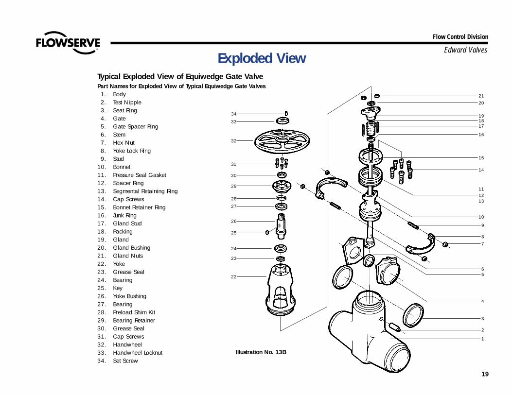
Typical Exploded View of Equiwedge Gate ValvePart Names for Exploded View of Typical Equiwedge Gate Valves1. Body2. Test Nipple3. Seat Ring4. Gate5. Gate Spacer Ring6. Stem7. Hex Nut8. Yoke Lock Ring9. Stud
10. Bonnet11. Pressure Seal Gasket12. Spacer Ring13. Segmental Retaining Ring14. Cap Screws15. Bonnet Retainer Ring16. Junk Ring17. Gland Stud18. Packing19. Gland20. Gland Bushing21. Gland Nuts22. Yoke23. Grease Seal24. Bearing25. Key26. Yoke Bushing27. Bearing28. Preload Shim Kit29. Bearing Retainer30. Grease Seal31. Cap Screws32. Handwheel33. Handwheel Locknut34. Set Screw
Flow Control Division
Edward ValvesReassembly Instructions
The yoke bushing threads should becleaned in the same manner as the otherthreaded parts and regreased. The samelubricant should be used to regrease theyoke bushing bearings through the lubefitting. See pg. 8 for lubricant recommen-dations. Follow these guidelines:1. Replace the stem packing.2. Replace the pressure seal gasket with a
new gasket.3. Observe all match marks assigned dur-
ing disassembly so that part orientationis maintained.
4. Reassemble stud nuts and cap screwsusing a torque wrench. See Table 2, pg.7, for recommended torque values.
5. When reassembling the bearings in theyoke assembly, use the following proce-dure to obtain the proper clearance orpreload.
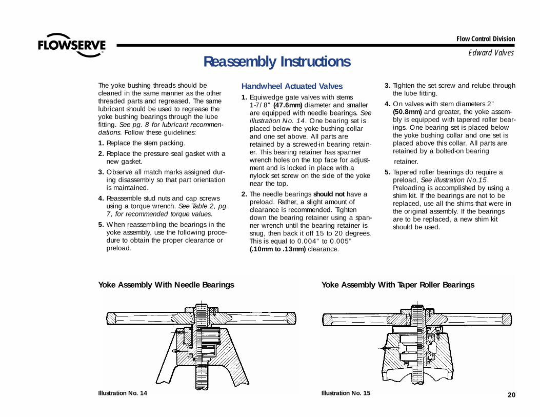
Handwheel Actuated Valves1. Equiwedge gate valves with stems
1-7/8” (47.6mm) diameter and smallerare equipped with needle bearings. Seeillustration No. 14. One bearing set isplaced below the yoke bushing collarand one set above. All parts areretained by a screwed-in bearing retain-er. This bearing retainer has spannerwrench holes on the top face for adjust-ment and is locked in place with anylock set screw on the side of the yokenear the top.
2. The needle bearings should not have apreload. Rather, a slight amount ofclearance is recommended. Tightendown the bearing retainer using a span-ner wrench until the bearing retainer issnug, then back it off 15 to 20 degrees.This is equal to 0.004” to 0.005”(.10mm to .13mm) clearance.
3. Tighten the set screw and relube throughthe lube fitting.
4. On valves with stem diameters 2”(50.8mm) and greater, the yoke assem-bly is equipped with tapered roller bear-ings. One bearing set is placed belowthe yoke bushing collar and one set isplaced above this collar. All parts areretained by a bolted-on bearing retainer.
5. Tapered roller bearings do require apreload, See illustration No.15.Preloading is accomplished by using ashim kit. If the bearings are not to bereplaced, use all the shims that were inthe original assembly. If the bearingsare to be replaced, a new shim kitshould be used.
Yoke Assembly With Needle Bearings
Illustration No. 14
Yoke Assembly With Taper Roller Bearings
Illustration No. 15 20
21
Flow Control Division
Edward ValvesReassembly instructions (cont.)
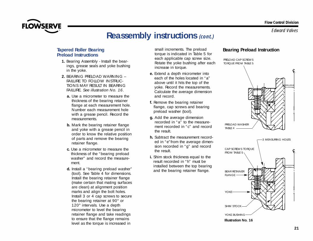
Tapered Roller Bearing Preload Instructions
1. Bearing Assembly - Install the bear-ings, grease seals and yoke bushingin the yoke.
2. BEARING PRELOAD WARNING –FAILURE TO FOLLOW INSTRUC-TIONS MAY RESULT IN BEARINGFAILURE. See illustration No. 16.a. Use a micrometer to measure the
thickness of the bearing retainerflange at each measurement hole.Number each measurement holewith a grease pencil. Record themeasurements.
b. Mark the bearing retainer flangeand yoke with a grease pencil inorder to know the relative positionof parts and remove the bearingretainer flange.
c. Use a micrometer to measure thethickness of the “bearing preloadwasher” and record the measure-ment.
d. Install a “bearing preload washer”(tool). See Table 4 for dimensions.Install the bearing retainer flange(make certain that mating surfacesare clean) at alignment positionmarks and align the bolt holes.Install 3 or 4 cap screws to securethe bearing retainer at 90° or120° intervals. Use a depthmicrometer to level the bearingretainer flange and take readingsto ensure that the flange remainslevel as the torque is increased in
small increments. The preloadtorque is indicated in Table 5 foreach applicable cap screw size.Rotate the yoke bushing after eachincrease in torque.
e. Extend a depth micrometer intoeach of the holes located in “a”above until it hits the top of theyoke. Record the measurements.Calculate the average dimensionand record.
f. Remove the bearing retainerflange, cap screws and bearingpreload washer (tool).
g. Add the average dimensionrecorded in “a” to the measure-ment recorded in “c” and recordthe result.
h. Subtract the measurement record-ed in “e”from the average dimen-sion recorded in “g” and recordthe result.
i. Shim stock thickness equal to theresult recorded in “h” must beinstalled between the top bearingand the bearing retainer flange.
Illustration No. 16
Bearing Preload Instruction
PRELOAD CAP SCREWSTORQUE FROM TABLE 5
PRELOAD WASHER TABLE 4
CAP SCREWS TORQUEFROM TABLE 5
BEAR RETAINERFLANGE
YOKE
SHIM STOCK
YOKE BUSHING
3 MEASURING HOLES

22
Flow Control Division
Edward ValvesReassembly Instructions (cont.)
j. Install the bearing retainer flange onthe yoke (make certain that the matingsurfaces are clean), align the positionmarks and align the holes in the bear-ing retainer flange with the holes inthe yoke. Install 3 or 4 cap screws at900 intervals. Use a depth micrometerto level the bearing retainer flangeand take readings to ensure that theflange remains level while the torque
is increased in small increments.Rotate the yoke bushing after eachincrease in torque. Apply a preloadtorque indicated on Table 5 to the capscrews, use a depth micrometer totake measurements and compare themeasurements with those taken in step(a) above. If the measurements are thesame as those recorded in step “a”,then the flange has bottomed on the
yoke. If the measurements are greaterthan “a” measurements, then theflange has not bottomed and the bear-ing preload procedure should berepeated. Install the remaining capscrews and tighten in a star patternuntil the torque indicated in Table 6 isdeveloped. Be careful to keep thebearing retainer flange level whiletorque is applied to the cap screws.
Table 4—Dimensions For Bearing Preload Washer - in inches (mm)
Valve Stem Diameter Washer OD Washer ID Washer Thickness+.005 (±.13) +.010 (±.25) +.001 (±.03)
2.000 (50.80) 5.100 (129.54) 4.56 (115.8) .187 (4.75)2.125 (53.98) 5.100 (129.54) 4.56 (115.8) .187 (4.75)2.250 (57.15) 5.687 (144.45) 5.15 (130.8) .187 (4.75)2.375 (60.32) 6.090 (154.69) 5.38 (136.7) .187 (4.75)2.500 (63.50) 7.110 (180.59) 6.40 (162.6) .187 (4.75)2.625 (66.68) 7.075 (179.70) 6.36 (161.5) .187 (4.75)2.750 (69.85) 6.985 (177.42) 6.30 (160.0) .187 (4.75)2.875 (73.02) 8.110 (205.99) 7.34 (185.9) .187 (4.75)3.000 (76.20) 8.985 (228.22) 8.12 (206.2) .187 (4.75)3.250 (82.55) 9.985 (253.62) 9.00 (228.6) .187 (4.75)3.500 (88.90) 11.360 (288.54) 10.25 (260.3) .187 (4.75)3.750 (95.25) 12.485 (317.12) 11.25 (285.8) .187 (4.75)4.250 (107.95) 12.485 317.12) 11.25 (285.8) .187 (4.75)
Table 5—Bearing Retainer Preload TorqueCap Screws Threads Per Torque In Ft. Torque No. of Cap
Diameter Inch Pounds In NM Screws3/4 10 20 27 3 or 47/8 9 35 47 3 or 41 8 50 68 4
1-1/4 7 135 183 4
Table 5ACap Screws Pitch Torque No. of Cap
Diameter in NM Screws16 2 120 3 or 420 2.5 240 3 or 424 3 400 3 or 430 3.5 880 4
Table 6—Bearing Retainer Final TorqueCap Screws Threads Per Torque in Ft. Torque
Diameter Inch Pounds in NM3/4 10 165 2247/8 9 265 3601 8 405 550
1-1/4 7 895 1215
Table 6ACap Screws Pitch Torque
Diameter in NM16 2 12020 2.5 24024 3 40030 3.5 880
23
Flow Control Division
Edward Valves
Reassembly Instructions for Valves with Composite Pressure Seal Gaskets OnlyIt is important to determine that the newcomposite pressure seal gasket:, the bon-net and the body sealing area are in satis-factory condition before installation. Thefollowing steps will help ensure superiorperformance of the gasket.
1. Carefully inspect the body bore andbonnet O.D. sealing surfaces.Remove any raised metal from theentry chambers and gasket chamberregions. Repair any gouges in thesealing region in accordance withthe instructions on pg. 10.
2. Inspect the new composite gasket.Note: All composite gaskets havecracks and wrinkles in the flexiblegraphite. This is a normal result ofthe forming process and will notaffect gasket performance.
3. Be sure the anti-extrusion rings aretightly bonded to the graphitic gas-ket, so they will not touch the bodyduring assembly, If any of the anti-extrusion rings are loose, carefullyscrape away all flexible graphiteleft on the anti-extrusion ring surfaceand re-bond to the graphite surfaceusing Loctite 454 or other suitablecontact cement. The ends of theouter rings should touch after bond-ing. There should be an approxi-mate .020 ± .005 inch gap at theends of the inner ring.
4. Place the gasket on the bonnet withthe two anti-extrusion rings facingup as shown in the illustration. Thegasket should fit snugly around thebonnet, and the gasket O.D. should
not exceed the O.D. of the bonnet.This will ensure that the gasket doesnot catch on the body and “ener-gize” prematurely.
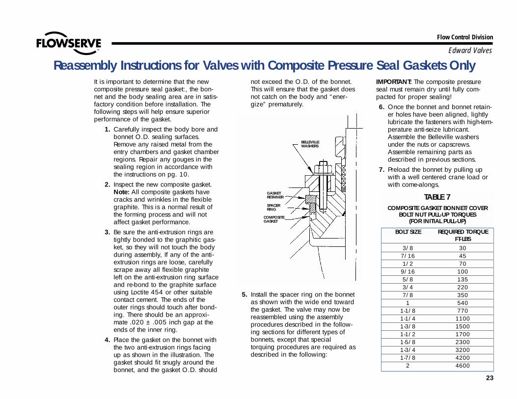
5. Install the spacer ring on the bonnetas shown with the wide end towardthe gasket. The valve may now bereassembled using the assemblyprocedures described in the follow-ing sections for different types ofbonnets, except that specialtorquing procedures are required asdescribed in the following:
IMPORTANT: The composite pressureseal must remain dry until fully com-pacted for proper sealing!6. Once the bonnet and bonnet retain-
er holes have been aligned, lightlylubricate the fasteners with high-tem-perature anti-seize lubricant.Assemble the Belleville washersunder the nuts or capscrews.Assemble remaining parts asdescribed in previous sections.
7. Preload the bonnet by pulling upwith a well centered crane load orwith come-alongs.
BELLEVILLEWASHERS
GASKETRETAINER
SPACERRING
COMPOSITEGASKET
TABLE 7COMPOSITE GASKET BONNET/COVER
BOLT/NUT PULL-UP TORQUES(FOR INITIAL PULL-UP)
BOLT SIZE REQUIRED TORQUEFT-LBS
3/8 307/16 451/2 709/16 1005/8 1353/4 2207/8 3501 540
1-1/8 7701-1/4 11001-3/8 15001-1/2 17001-5/8 23001-3/4 32001-7/8 4200
2 4600
24
Flow Control Division
Edward Valves
8. Initially compress the pressure sealgasket making sure that the bonnetdoes not cock in the body.
9. While maintaining the pull up load,torque the bonnet/cover bolts even-ly using a varying star pattern, untilthe fastener torques reach a valueof 2/3 the torque given in Table 7,pg. 23.
10. After reaching 2/3 of the torquevalue given in Table 7, torque thebonnet nuts in small torque incre-ments, with no more than 1/6 turnper tightening round, using a vary-ing star pattern, until the full torquevalue given in Table 7 is reached.
11. Re-torque the bolts at the finaltorque value several times, until thegasket no longer compresses. Thisstep is necessary due to the highresilience of the graphitic gasket.
12. Complete remaining valve assemblyin accordance with the appropriatepreceding section of this manual.
13. When the valve is next under pres-sure, either during system hydrostat-ic test or when put in service, re-torque the bolts to the torque valuesgiven in Table 2, pg. 7.
CAUTIONDo not use the torque
values in Table 7 while the valve is under pressure.
Reassembly Instructions for Valves with Composite Pressure Seal Gaskets Only (cont.)
Reassembly Instructions for Valves with Metal Gaskets OnlyType I Pressure Seal BonnetSee Illustration No. 7, pg. 14
1. Place one gate half on a clean ply-wood board. Place the stem T-headin the recess in the gate.
2. Place the gate spacer ring into thecounterbore in one gate half. Placethe other gate half on top, engag-ing the spacer ring and stem.Holding the gate halves together,lift the stem and lower assemblyinto the body, engaging the gateguide rails with the grooves in thebody. Lower the gate to the seats.
3. Assemble a new pressure seal gas-ket and the junk ring on the bon-
net. Lift the bonnet assembly overthe stem and lower it into the body.Be very careful not to mar the pres-sure seal gasket or other machinedsurfaces.
4. Place the gasket retainer plate andthrust washer on the body andalign cap screw holes on the gas-ket retainer plate with the bodyholes.
5. Place the bonnet retainer plateover the stem and start threadingonto the bonnet.
6. Place the gland over the stem.7. Place the yoke over the stem and
engage the stem threads by turningthe yoke bushing counterclockwise.
When the yoke contacts the gasketretainer plate, align the cap screwholes and continue to turn the yokebushing until the stem contacts thebackseat. This will pull the bonnetand gasket up against the gasketretainer and the yoke flange upagainst the body.
8. Assemble the yoke flange capscrews and tighten in a star patternusing a torque wrench to values asshown in Table 2, pg. 7.
9. With the bonnet retainer capscrews flush on the bottom of thebonnet retainer, screw the bonnetretainer down until it contacts thethrust washer. Now back it off
25
Flow Control Division
Edward Valves
1/8” (3mm) and align the glandbolts with the yoke windows.
10. Tighten the bonnet retainer capscrews using a torque wrench in astar pattern to the values shown onTable 2, pg. 7. See step 13 below.
11. Repack the packing chamber fol-lowing instructions on pg. 6. Placethe gland in position and tightenthe gland nuts.
12. Reassemble the handwheel,(oractuator) using the reverse of theinstructions for disassembly.
13. After the valve is pressurized,retighten the bonnet retainer capscrews using the same torque val-ues in step 10. This is important.
Types IIA & IIB Pressure Seal BonnetSee Illustration Nos. 8 & 9. pg. 15
1. Place one gate half, seat facedown, on a bed of clean rags orplywood board. Place the stem T-head into the recess in the gate.
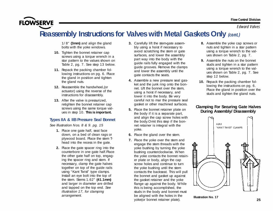
2. Place the gate spacer ring into thecounterbore in one gate half.Placethe other gate half on top, engag-ing the spacer ring and stem. Ifnecessary, clamp the gate halvestogether on top of the guide railsusing “Kant Twist” type clamps.Install an eye bolt into the top ofthe stem. Stems 1.62” (41.1mm)and larger in diameter are drilledand tapped on the top end. Seeillustration 17, for clampingarrangement.
3. Carefully lift the stem-gate assem-bly using a hoist if necessary toavoid scratching the stem or gatesurfaces, and lower the assemblypart way into the body with theguide rails fully engaged with theguide grooves. Remove the clampsand lower the assembly until thegate contacts the seats.
4. Assemble a new pressure seal gas-ket and the junk ring onto the bon-net. Lift the bonnet over the stem,using a hoist if necessary, andlower it into the body. Be verycareful not to mar the pressure sealgasket or other machined surfaces.
5. Place the bonnet retainer plate onthe body if it is a separate part,and align the cap screw holes withthe body.Omit this step if the bon-net retainer is integral with theyoke.
6. Place the gland over the stem.7. Place the yoke over the stem and
engage the stem threads with theyoke bushing by turning the yokebushing counterclockwise. Whenthe yoke contacts the bonnet retain-er plate or body, align the capscrew holes and continue to turnthe yoke bushing until the stemcontacts the backseat. This will pullthe bonnet and gasket up againstthe gasket retainer and the yokeflange up against the body. Whilethis is being accomplished, thestuds in the body and bonnet mustbe aligned with the holes in theyoke(or bonnet retainer plate).
8. Assemble the yoke cap screws ornuts and tighten in a star patternusing a torque wrench to the val-ues shown on Table 2, pg. 7.
9. Assemble the nuts on the bonnetstuds and tighten in a star patternusing a torque wrench to the val-ues shown on Table 2, pg. 7. Seestep 12 below.
10. Repack the packing chamber fol-lowing the instructions on pg. 6.Place the gland in position over thestuds and tighten the gland nuts.
Reassembly Instructions for Valves with Metal Gaskets Only (cont.)
Clamping For Securing Gate Halves During Assembly/Disassembly
Illustration No. 17
AJAX“KANT TWIST” CLAMPS
26
Flow Control Division
Edward Valves
11. Reassemble the handwheel, (oractuator) using the reverse of theinstructions for disassembly.
12. After the valve is pressurized,retighten the bonnet retainer nutsusing same torque values as inStep 9. This is important.
Type III Pressure Seal BonnetSee Illustration No. 10, pg. 16
1. Place one gate half on a clean ply-wood board. Place the stem T-headinto the recess in the gate.
2. Place the gate spacer ring into thecounterbore in one gate half. Placethe other gate half on top, engag-ing the spacer ring and stem.Holding the gate halves together,lift the stem and lower the assem-bly into the body engaging thegate guide rails with the groove inthe body. Lower the gate to theseats.
3. Assemble a new pressure seal gas-ket, the spacer ring and junk ringon the bonnet. Lift the bonnetassembly over the stem and lowerinto the body. Be very careful notto mar the pressure seal gasket orother machined surfaces.
4. Assemble the gasket retainer seg-ments into the groove.
5. Place the thrust washer on thebody, and the bonnet retainerplate on top of the body. Lift thestem assembly up so that the bon-net penetrates the gasket retainer
segments and engages the threadsof the bonnet retainer and bonnet.The bonnet retainer cap screwshould be engaged so they areflush. Lift the stem assembly up andscrew the bonnet retainer downuntil it contacts the body. Nowback it off about 1/8” (3mm) andalign the gland bolts for correct ori-entation.
6. Place the gland over the stem.7. Place the yoke over the stem and
engage the stem threads by turningthe yoke bushing counterclockwise.When the yoke contacts the body,align the cap screw holes and con-tinue to turn the yoke bushing untilthe stem contacts the backseat firm-ly. This will pull the bonnet, gasket,and spacer ring up against thebonnet retainer and the yoke upagainst the body.
8. Assemble the yoke flange capscrews and tighten the cap screwsusing a torque wrench to the val-ues shown on Table 2, pg. 7. Seestep 12 below.
9. Tighten the bonnet retainer capscrews in a star pattern using atorque wrench to the values shownon Table 2, pg. 7.
10. Repack the packing chamber, fol-lowing the instructions on pg. 6.Place the gland in position andtighten the gland nuts.
11. Reassemble the handwheel, (oractuator) using the reverse of the
instructions for disassembly.12. After the valve is pressurized,
retighten the bonnet retainer capscrews, step 8, using the sametorque values. This is important.
Type IV & V Pressure Seal BonnetSee Illustration Nos. 11 & 12, pg. 17
1. Place one gate half seat face downon a bed of clean rags or plywoodboard. Place the stem T-head intothe recess in the gate.
2. Place the gate spacer ring into thecounterbore in one gate half. Placethe other gate half on top, engag-ing the spacer ring and stem.Clamp the gate halves togethernear the top of the guide rails.Place an eyebolt in the top end ofthe stem. Stems 1.62” (41.1mm)and larger are drilled and tappedon the top end. See illustration No.17, pg. 25, for clamping arrange-ment.
3. Carefully lift the stem-gate assem-bly, using a hoist in the eyebolt ifnecessary, so as to avoid scratch-ing the stem or gate surfaces.Lower the assembly part way intothe body with the gate guide railsengaged with the body guidegroove. Remove the clamps andlower the assembly until the gatecontacts the seats.
Reassembly Instructions for Valves with Metal Gaskets Only (cont.)
27
Flow Control Division
Edward Valves
Reassembly Instructions for Valves with Metal Gaskets Only (cont.)4. Assemble a new pressure seal gas-
ket, the spacer ring, junk ring andgland on the bonnet. Lift the bon-net using a hoist if necessary, andplace it over the stem and lowerinto the body. Be very careful notto mar the pressure seal gasket orother machined surfaces.
5. Install the gasket retainer ring seg-ments in the body groove. Placethe bonnet retainer over the stemonto the top of the body.
6. Lift the stem and bonnet assemblyup through the gasket retainer andrealign the studs with the bonnetretainer and match marks.
7. Assemble the nuts on the bonnetretainer studs and snug them up.
8. Lift the yoke assembly over thestem and engage the stem threadsby turning the yoke bushing coun-terclockwise. When the yoke con-tacts the body, align the bolt holes(or match mark) and continue toturn the yoke bushing until the stemcontacts the backseat firmly.
9. Install the cap screw (or yoke lockring) and tighten the cap screws(or studs and nuts) to the torquevalues shown on Table 2, pg. 7.See step 13 below.
10. Tighten the bonnet retainer nutscarefully using a torque wrench ina star pattern to the values shownon Table 2, pg. 7.
11. Install new packing following theinstructions on pg. 6. Place thegland in position and tighten thegland bolts evenly.
12. Reassemble the handwheel (oractuator) using the reverse of theinstructions for disassembly.
13. After the valve has been pressur-ized,retighten the bonnet retainernuts to the same torque valuesused in step 10. This is important.
28
Flow Control Division
Edward Valves
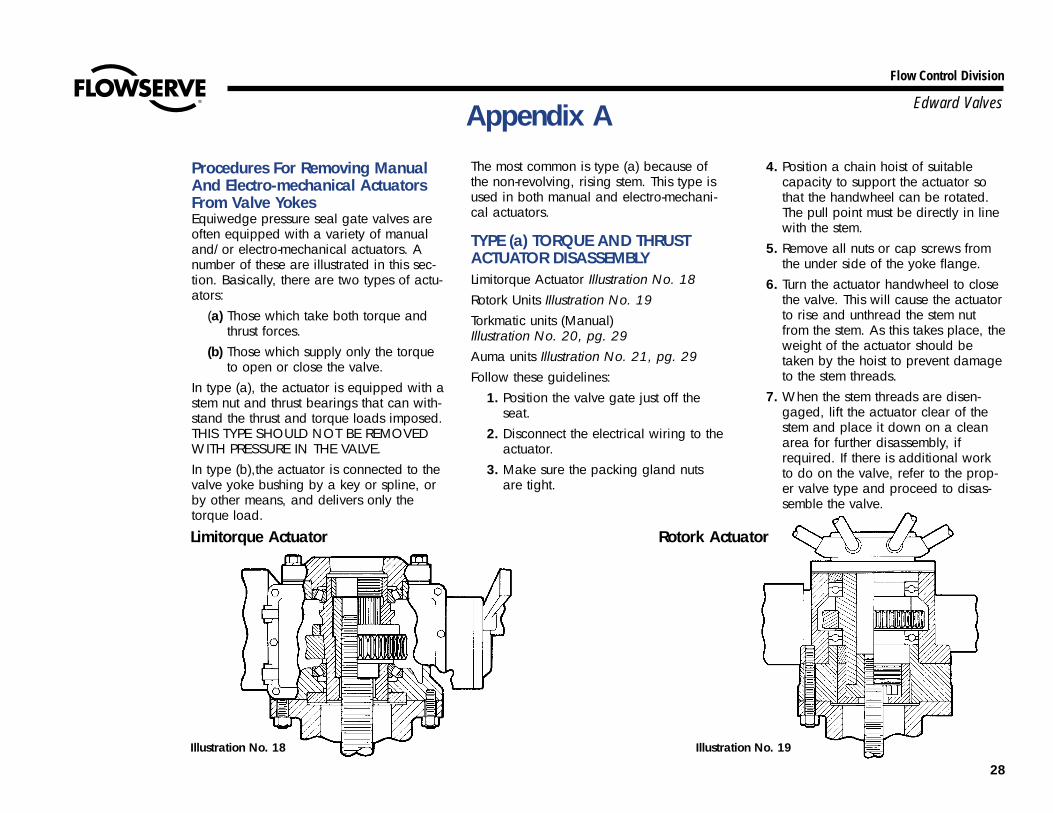
Procedures For Removing ManualAnd Electro-mechanical ActuatorsFrom Valve YokesEquiwedge pressure seal gate valves areoften equipped with a variety of manualand/or electro-mechanical actuators. Anumber of these are illustrated in this sec-tion. Basically, there are two types of actu-ators:
(a) Those which take both torque andthrust forces.
(b) Those which supply only the torqueto open or close the valve.
In type (a), the actuator is equipped with astem nut and thrust bearings that can with-stand the thrust and torque loads imposed.THIS TYPE SHOULD NOT BE REMOVEDWITH PRESSURE IN THE VALVE.In type (b),the actuator is connected to thevalve yoke bushing by a key or spline, orby other means, and delivers only thetorque load.
The most common is type (a) because ofthe non-revolving, rising stem. This type isused in both manual and electro-mechani-cal actuators.
TYPE (a) TORQUE AND THRUSTACTUATOR DISASSEMBLYLimitorque Actuator Illustration No. 18Rotork Units Illustration No. 19Torkmatic units (Manual)Illustration No. 20, pg. 29Auma units Illustration No. 21, pg. 29Follow these guidelines:
1. Position the valve gate just off theseat.
2. Disconnect the electrical wiring to theactuator.
3. Make sure the packing gland nutsare tight.
4. Position a chain hoist of suitablecapacity to support the actuator sothat the handwheel can be rotated.The pull point must be directly in linewith the stem.
5. Remove all nuts or cap screws fromthe under side of the yoke flange.
6. Turn the actuator handwheel to closethe valve. This will cause the actuatorto rise and unthread the stem nutfrom the stem. As this takes place, theweight of the actuator should betaken by the hoist to prevent damageto the stem threads.
7. When the stem threads are disen-gaged, lift the actuator clear of thestem and place it down on a cleanarea for further disassembly, ifrequired. If there is additional workto do on the valve, refer to the prop-er valve type and proceed to disas-semble the valve.
Appendix A
Limitorque Actuator Rotork Actuator
Illustration No. 18 Illustration No. 19
29
Flow Control Division
Edward Valves
Appendix A (cont.)
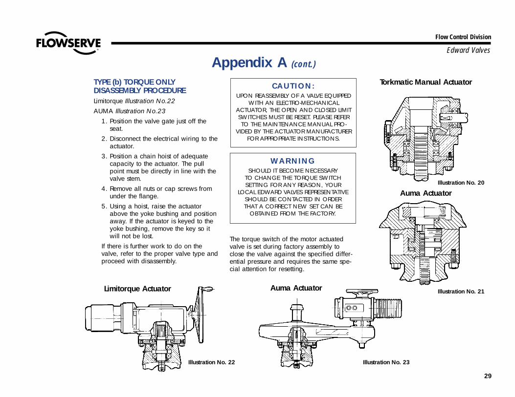
TYPE (b) TORQUE ONLYDISASSEMBLY PROCEDURELimitorque Illustration No.22AUMA Illustration No.23
1. Position the valve gate just off theseat.
2. Disconnect the electrical wiring to theactuator.
3. Position a chain hoist of adequatecapacity to the actuator. The pullpoint must be directly in line with thevalve stem.
4. Remove all nuts or cap screws fromunder the flange.
5. Using a hoist, raise the actuatorabove the yoke bushing and positionaway. If the actuator is keyed to theyoke bushing, remove the key so itwill not be lost.
If there is further work to do on thevalve, refer to the proper valve type andproceed with disassembly.
CAUTION:UPON REASSEMBLY OF A VALVE EQUIPPED
WITH AN ELECTRO-MECHANICALACTUATOR, THE OPEN AND CLOSED LIMITSWITCHES MUST BE RESET. PLEASE REFERTO THE MAINTENANCE MANUAL PRO-
VIDED BY THE ACTUATOR MANUFACTURERFOR APPROPRIATE INSTRUCTIONS.
WARNINGSHOULD IT BECOME NECESSARY
TO CHANGE THE TORQUE SWITCHSETTING FOR ANY REASON, YOUR
LOCAL EDWARD VALVES REPRESENTATIVESHOULD BE CONTACTED IN ORDER THAT A CORRECT NEW SET CAN BE
OBTAINED FROM THE FACTORY.
The torque switch of the motor actuatedvalve is set during factory assembly toclose the valve against the specified differ-ential pressure and requires the same spe-cial attention for resetting.
Illustration No. 20
Illustration No. 21
Illustration No. 23Illustration No. 22
Torkmatic Manual Actuator
Auma Actuator
Limitorque Actuator Auma Actuator
30
Flow Control Division
Edward Valves
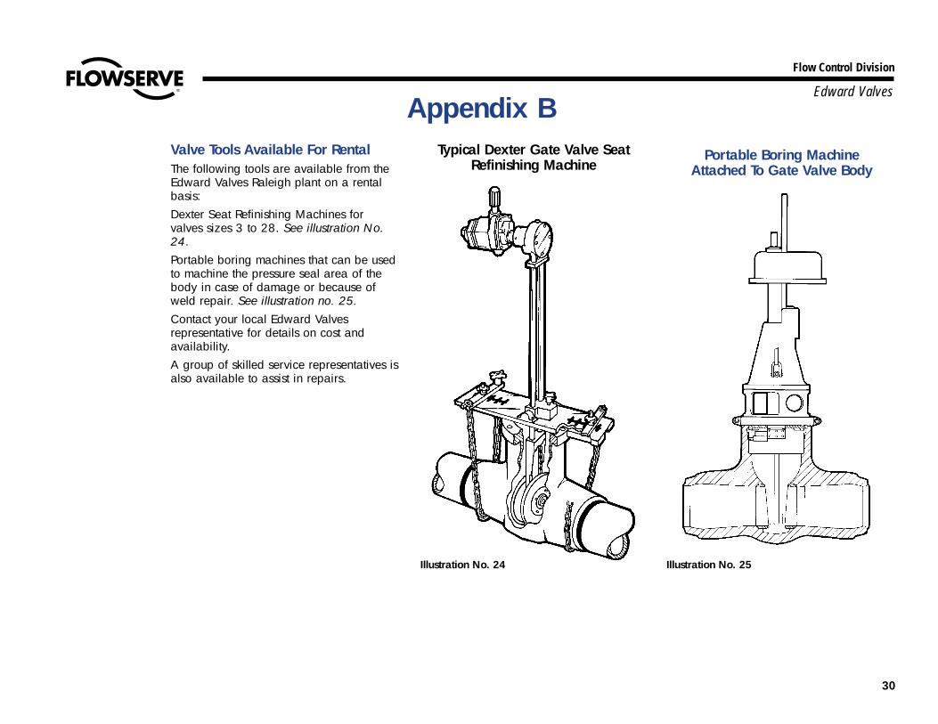
Valve Tools Available For RentalThe following tools are available from theEdward Valves Raleigh plant on a rentalbasis:Dexter Seat Refinishing Machines forvalves sizes 3 to 28. See illustration No.24.Portable boring machines that can be usedto machine the pressure seal area of thebody in case of damage or because ofweld repair. See illustration no. 25.Contact your local Edward Valvesrepresentative for details on cost andavailability.A group of skilled service representatives isalso available to assist in repairs.
Appendix BTypical Dexter Gate Valve Seat
Refinishing MachinePortable Boring Machine
Attached To Gate Valve Body
Illustration No. 25Illustration No. 24
Flow Control Division
Edward Valves
Flowserve Corporation has established industry leadership in the design and manufacture of its products. When properly selected, this Flowserve product is designed to perform its intended function safely during its useful life.However, the purchaser or user of Flowserve products should be aware that Flowserve products might be used in numerous applications under a wide variety of industrial service conditions. Although Flowserve can (and often does)provide general guidelines, it cannot provide specific data and warnings for all possible applications. The purchaser/user must therefore assume the ultimate responsibility for the proper sizing and selection, installation, operation,and maintenance of Flowserve products. The purchaser/user should read and understand the Installation Operation Maintenance (IOM) instructions included with the product, and train its employees and contractors in the safe use ofFlowserve products in connection with the specific application.
While the information and specifications contained in this literature are believed to be accurate, they are supplied for informative purposes only and should not be considered certified or as a guarantee of satisfactory results byreliance thereon. Nothing contained herein is to be construed as a warranty or guarantee, express or implied, regarding any matter with respect to this product. Because Flowserve is continually improving and upgrading its productdesign, the specifications, dimensions and information contained herein are subject to change without notice. Should any question arise concerning these provisions, the purchaser/user should contact Flowserve Corporation at anyone of its worldwide operations or offices.
© 2003 Flowserve Corporation, Irving, Texas, USA. Flowserve and Edward Valves are registered trademarks of Flowserve Corporation. V-378 R1 3/03 Printed in USA
FLOWSERVE CORPORATIONFLOW CONTROL DIVISIONEdward Valves1900 South Saunders StreetRaleigh, NC 27603 USA
Toll- Free Telephone Service(U. S. and Canada)Day: 1-800-225-6989
After Hours Customer Service1-800-543-3927
US Sales OfficesPhone: 919-832-0525Facsimile: 919-831-3369Facsimile: 919-831-3376
Visit Our Websitewww.edwardvalves.com
For more information about Flowserve Corporation, contact www.flowserve.com or call USA 1-800-225-6989.