er 1110-2-106 26 sept 1979mde.state.md.us/programs/water/damsafety/documents/www...er 1110-2-106 26...
TRANSCRIPT

ER 1110-2-10626 Sept 1979
APPENDIX D
ER 1110-2-10626 Sept 1979
33 CFR - CHAPTER II - PART 222
Appendix D to § 222.6 -- Recommended Guidelines for Safety Inspection of Dams
Department of the Army -- Office of the Chief of Engineers
Preface
The recommended guidelines for the safety inspection of dams were prepared to outlineprincipal factors to be weighed in the determination of existing or potential hazardsand to define the scope of activities to be undertaken in the safety inspection ofdams. The establishment of rigid criteria or standards is not intended. Safety must beevaluated in the light of peculiarities and local conditions at a particular dam andin recognition of the many factors involved, some of which may not be precisely known.This can only be done by competent, experienced engineering judgment, which theguidelines are intended to supplement and not supplant. The guidelines are intended tobe flexible, and the proper flexibility must be achieved through the employment ofexperienced engineering personnel.
Conditions found during the investigation which do not meet guideline recommendationsshould be assessed by the investigator as to their import from the standpoint of theinvolved degree of risk. Many deviations will not compromise project safety and theinvestigator is expected to identify them in this manner if that is the case. Otherswill involve various degrees of risk, the proper evaluation of which will afford abasis for priority of subsequent attention and possible remedial action.
The guidelines present procedures for investigating and evaluating existing conditionsfor the purpose of identifying deficiencies and hazardous conditions. The two phasesof investigation outlined in the guidelines are expected to accomplish only this anddo not encompass in scope the engineering which will be required to perform the designstudies for corrective modification work.
It is recognized that some States may have established or will adopt inspectioncriteria incongruous in some respects with these guidelines. In such instancesassessments of project safety should recognize the State's requirements as well asguideline recommendations.
The guidelines were developed with the help of several Federal agencies and many Stateagencies, professional engineering organizations, and private engineers. In reviewingtwo drafts of the guidelines they have contributed many helpful suggestions. Theircontributions are deeply appreciated and have made it possible to evolve a documentrepresenting a consensus of the engineering fraternity. As experience is gained withuse of the guidelines, suggestions for future revisions will be generated. All suchsuggestions should be directed to the Chief of Engineers, U.S. Army, DAEN-CWE-D,Washington, D.C. 20314.

ER 1110-2-10626 Sept 1979
Recommended Guidelines forSafety Inspection of Dams
Table of Contents
PrefaceChapter 1 – Introduction1.1 Purpose.1.2 Applicability.1.3 Authority.
Chapter 2 -- General Requirements2.1 Classification of dams.2.1.1 Size.2.1.2 Hazard potential.2.2 Selection of dams to be investigated.2.3 Technical investigations.2.4 Qualifications of investigators.2.5 Reports.
Chapter 3 -- Phase I Investigation3.1 Purpose.3.2 Scope.3.3 Engineering data.3.4 Field inspections.3.5 Evaluation of hydraulic and hydrologic features.3.5.1 Design data.3.5.2 Experience data.3.6 Evaluation of structural stability.3.6.1 Design and construction data.3.6.2 Operating records.3.6.3 Post construction changes.3.6.4 Seismic stability.
Chapter 4 -- Phase II Investigation4.1 Purpose.4.2 Scope.4.3 Hydraulic and hydrologic analysis.4.3.1 Maximum water surface based on SDF peak inflow.4.3.1.1 Peak for 100-year flood.4.3.1.2 Peak for PMF or fraction thereof.4.3.2 Maximum water surface based on SDF hydrograph.4.3.3 Acceptable procedures.4.3.4 Freeboard allowances.4.4 Stability investigations.4.4.1 Foundation and material investigations.4.4.2 Stability assessment.4.4.2.1 Seismic stability.4.4.2.2 Clay shale foundation.4.4.3 Embankment dams.4.4.3.1 Liquefaction.4.4.3.2 Shear failure.4.4.3.3 Loading conditions.4.4.3.4 Safety factors.4.4.3.5 Seepage failure.4.4.3.6 Seepage analyses.4.4.4 Concrete dams and appurtenant structures.4.4.4.1 Requirements for stability.4.4.4.2 Loads.4.4.4.3 Stresses.4.4.4.4 Overturning.4.4.4.5 Sliding.

ER 1110-2-10626 Sept 1979
4.4.4.5.1 Sliding resistance.4.4.4.5.2 Downstream resistance.4.4.4.5.3 Safety factor.
Chapter 5 -- Reports5.1 General.5.2 Preparation of report.5.2.1 Phase I reports.5.2.2 Phase II reports.
TablesTable 1 Size classification.Table 2 Hazard potential classification.Table 3 Hydrologic evaluation guidelines.Table 4 Factors of safety (embankment dams).
FiguresFigure 1 Seismic zone map of contiguous States.Figure 2 Seismic zone map of California, Nevada and Arizona.Figure 3 Seismic zone map of Alaska.Figure 4 Seismic zone map of Hawaii.Figure 5 Design envelope for Case I (Table 4).Figure 6 Design envelope for Cases II and III (Table 4).
AppendixesAppendix I Engineering dataAppendix II Inspection itemsAppendix III Public Law 92-367

ER 1110-2-10626 Sept 1979
RECOMMENDED GUIDELINES FOR SAFETY INSPECTION OF DAMS
CHAPTER 1 - Introduction
1.1. Purpose. This document provides recommended guidelines for the inspection andevaluation of dams to determine if they constitute hazards to human life or property.1.2. Applicability. The procedures and guidelines outlined in this document apply tothe inspection and evaluation of all dams as defined in the National Dam InspectionAct, Public Law 92-367. Included in this program are all artificial barriers togetherwith appurtenant works which impound or divert water and which (1) are twenty-fivefeet or more in height or (2) have an impounding capacity of fifty acre-feet or more.Not included are barriers which are six feet or less in height, regardless of storagecapacity, or barriers which have a storage capacity at maximum water storage elevationof fifteen acre-feet or less regardless of height.
1.3. Authority. The Dam Inspection Act, Public Law 92-367 (Appendix III), authorizedthe Secretary of the Army, through the Corps of Engineers, to initiate a program ofsafety inspection of dams throughout the United States. The Chief of Engineers issuesthese guidelines pursuant to that authority. Chapter 2 -- General Requirements2.1. Classification of dams. Dams should be classified in accordance with size andhazard potential in order to formulate a priority basis for selecting dams to beincluded in the inspection program and also to provide compatibility between guidelinerequirements and involved risks. When possible the initial classifications should bebased upon information listed in the National Inventory of Dams with respect to size,impoundment capacity and hazard potential. It may be necessary to reclassify dams whenadditional information becomes available.
CHAPTER 2 – GENERAL REQUIREMENTS
2.1.1. Size. The classification for size based on the height of the dam and storagecapacity should be in accordance with Table 1. The height of the dam is establishedwith respect to the maximum storage potential measured from the natural bed of thestream or watercourse at the downstream toe of the barrier, or if it is not across astream or watercourse, the height from the lowest elevation of the outside limit ofthe barrier, to the maximum water storage elevation. For the purpose of determiningproject size, the maximum storage elevation may be considered equal to the top of damelevation. Size classification may be determined by either storage or height,whichever gives the larger size category.
TABLE 1
SIZE CLASSIFICATION
ImpoundmentCategory Storage (Ac-ft) Height (Ft)Small < 1000 and � 50 < 40 and � 25Intermediate � 1000 and < 50,000 � 40 and < 100Large � 50,000 � 100
2.1.2. Hazard Potential. The classification for potential hazards should be inaccordance with Table 2. The hazards pertain to potential loss of human life orproperty damage in the area downstream of the dam in event of failure or misoperationof the dam or appurtenant facilities. Dams conforming to criteria for the low hazardpotential category generally will be located in rural or agricultural areas wherefailure may damage farm buildings, limited agricultural land, or township and countryroads. Significant hazard potential category structures will be those located inpredominantly rural or agricultural areas where failure may damage isolated homes,secondary highways or minor railroads or cause interruption of use or service ofrelatively important public utilities. Dams in the high hazard potential category willbe those located where failure may cause serious damage to homes, extensiveagricultural, industrial and commercial facilities, important public utilities, mainhighways, or railroads.

ER 1110-2-10626 Sept 1979
TABLE 2
HAZARD POTENTIAL CLASSIFICATION
Category Loss of Life(Extent of Development)
Economic Loss(Extent of Development)
Low None Expected (No permanentstructures for humanhabitation)
Minimal (Undeveloped tooccasional structures oragricultural)
Significant Few (No urban developmentand no more than a smallnumber of inhabitablestructures)
Appreciable (Notableagriculture, industry, orstructures)
High More than a few Excessive (Extensivecommunity, industry, oragriculture)
2.2. Selection of dams to be investigated. The selection of dams to be investigatedshould be based upon an assessment of existing developments in flood hazard areas.Those dams possessing a hazard potential classified high or significant as indicatedin Table 2 should be given first and second priorities, respectively, in theinspection program. Inspection priorities within each category may be developed from aconsideration of factors such as size classification and age of the dam, thepopulation size in the downstream flood area, and potential developments anticipatedin flood hazard areas.
2.3. Technical Investigations. A detailed, systematic, technical inspection andevaluation should be made of each dam selected for investigation in which thehydraulic and hydrologic capabilities, structural stability and operational adequacyof project features are analyzed and evaluated to determine if the dam constitutes adanger to human life or property. The investigation should vary in scope andcompleteness depending upon the availability and suitability of engineering data, thevalidity of design assumptions and analyses and the condition of the dam. The minimuminvestigation will be designated Phase I, and an in-depth investigation designatedPhase II should be made where deemed necessary. Phase I investigations should consistof a visual inspection of the dam, abutments and critical appurtenant structures, anda review of readily available engineering data. It is not intended to perform costlyexplorations or analyses during Phase I. Phase II investigations should consist of alladditional engineering investigations and analyses found necessary by results of thePhase I investigation.
2.4. Qualifications of investigators. The technical investigations should be conductedunder the direction of licensed professional engineers experienced in theinvestigation, design, construction and operation of dams, applying the disciplines ofhydrologic, hydraulic, soils and structural engineering and engineering geology. Allfield inspections should be conducted by qualified engineers, engineering geologistsand other specialists, including experts on mechanical and electrical operation ofgates and controls, knowledgeable in the investigation, design, construction andoperation of dams.
ER 1110-2-10626 Sept 1979
CHAPTER 3 - PHASE I INVESTIGATION
3.1. Purpose. The primary purpose of the Phase I investigation program is to identifyexpeditiously those dams which may pose hazards to human life or property.
3.2. Scope. The Phase I investigation will develop an assessment of the generalcondition with respect to safety of the project based upon available data and a visualinspection, determine any need for emergency measures and conclude if additionalstudies, investigation and analyses are necessary and warranted. A review will be madeof pertinent existing and available engineering data relative to the design,construction and operation of the dam and appurtenant structures, including electricaland mechanical operating equipment and measurements from inspection and performanceinstruments and devices; and a detailed systematic visual inspection will be performedof those features relating to the stability and operational adequacy of the project.Based upon findings of the review of engineering data and the visual inspection, anevaluation will be made of the general condition of the dam, including where possiblethe assessment of the hydraulic and hydrologic capabilities and the structuralstability.
3.3. Engineering data. To the extent feasible the engineering data listed in AppendixI relating to the design, construction and operation of the dam and appurtenantstructures, should be collected from existing records and reviewed to aid inevaluating the adequacy of hydraulic and hydrologic capabilities and stability of thedam. Where the necessary engineering data are unavailable, inadequate or invalid, alisting should be made of those specific additional data deemed necessary by theengineer in charge of the investigation and included in the Phase I report.
3.4. Field inspections. The field inspection of the dam, appurtenant structures,reservoir area, and downstream channel in the vicinity of the dam should be conductedin a systematic manner to minimize the possibility of any significant feature beingoverlooked. A detailed checklist should be developed and followed for each daminspected to document the examination of each significant structural and hydraulicfeature including electrical and mechanical equipment for operation of the controlfacilities that affect the safety of the dam.
3.4.1. Particular attention should be given to detecting evidence of leakage, erosion,seepage, slope instability, undue settlement, displacement, tilting, cracking,deterioration, and improper functioning of drains and relief wells. The adequacy andquality of maintenance and operating procedures as they pertain to the safety of thedam and operation of the control facilities should also be assessed.
3.4.2. Photographs and drawings should be used freely to record conditions in order tominimize descriptions.
3.4.3. The field inspection should include appropriate features and items, includingbut not limited to those listed in Appendix II, which may influence the safety of thedam or indicate potential hazards to human life or property.
3.5. Evaluation of Hydraulic and Hydrologic Features.
3.5.1. Design data. Original hydraulic and hydrologic design assumptions obtained fromthe project records should be assessed to determine their acceptability in evaluatingthe safety of the dam. All constraints on water control such as blocked entrances,restrictions on operation of spillway and outlet gates, inadequate energy dissipatorsor restrictive channel conditions, significant reduction in reservoir capacity bysediment deposits and other factors should be considered in evaluating the validity ofdischarge ratings, storage capacity, hydrographs, routings and regulation plans. Thedischarge capacity and/or storage capacity should be capable of safely handling therecommended spillway design flood for the size and hazard potential classification ofthe dam as indicated in Table 3. The hydraulic and hydrologic determinations fordesign as obtained from project records will be acceptable if conventional techniquessimilar to the procedures outlined in paragraph 4.3. were used in obtaining the data.When the project design flood actually used exceeds the recommended spillway design

ER 1110-2-10626 Sept 1979
flood, from Table 3, the project design flood will be acceptable in evaluating thesafety of the dam.
TABLE 3
HYDROLOGIC EVALUATION GUIDELINES
RECOMMENDED SPILLWAY DESIGN FLOODS
Hazard Size *Spillway Design Flood (SDF)
Low SmallIntermediateLarge
50 to 100-yr frequency100-yr to ½ PMF½ PMF to PMF
Significant SmallIntermediateLarge
100-yr to ½ PMF½ PMF to PMFPMF
High SmallIntermediateLarge
½ PMF to PMFPMFPMF
*The recommended design floods in this column represent the magnitude of the spillwaydesign flood (SDF), which is intended to represent the largest flood that need beconsidered in the evaluation of a given project, regardless of whether a spillway isprovided; i.e., a given project should be capable of safely passing the appropriateSDF. Where a range of SDF is indicated, the magnitude that most closely relates tothe involved risk should be selected.
100-yr = 100-Year Exceedence Interval. The flood magnitude expected to be exceeded, onthe average, of once in 100 years. It may also be expressed as an exceedencefrequency with a one-percent chance of being exceeded in any given year.
PMF = Probable Maximum Flood. The flood that may be expected from the most severecombination of critical meteorologic and hydrologic conditions that arereasonably possible in the region. The PMF is derived from probable maximumprecipitation (PMP), which information is generally available from theNational Weather Service, NOAA. Most Federal agencies apply reduction factorsto the PMP when appropriate. Reductions may be applied because rainfallisohyetals are unlikely to conform to the exact shape of the drainage basinand/or the storm is not likely to center exactly over the drainage basin. Insome cases local topography will cause changes from the generalized PMPvalues, therefore it may be advisable to contact Federal construction agenciesto obtain the prevailing practice in specific areas.
3.5.2. Experience data. In some cases where design data are lacking, an evaluation ofovertopping potential may be based on watershed characteristics and rainfall andreservoir records. An estimate of the probable maximum flood may also be developedfrom a conservative, generalized comparison of the drainage area size and themagnitude of recently adopted probable maximum floods for damsites in comparablehydrologic regions. Where the review of such experience data indicates that therecommended spillway design flood would not cause overtopping additional hydraulic andhydrologic determinations will be unnecessary.
3.6. Evaluation of structural stability. The Phase I evaluations of structuraladequacy of project features are expected to be based principally on existingconditions as revealed by the visual inspection, together with available design andconstruction information and records of performance. The objectives are to determinethe existence of conditions which are hazardous, or which with time might develop intosafety hazards, and to formulate recommendations pertaining to the need for anyadditional studies, investigations, or analyses. The results of this phase of the
ER 1110-2-10626 Sept 1979
inspection must rely very substantially upon the experience and judgment of theinspecting engineer.
3.6.1. Design and construction data. The principal design assumptions and analysesobtained from the project records should be assessed. Original design and constructionrecords should be used judiciously, recognizing the restricted applicability of suchdata as material strengths and permeabilities, geological factors and constructiondescriptions. Original stability studies and analyses should be acceptable ifconventional techniques and procedures similar to those outlined in paragraph 4.4 wereemployed, provided that review of operational and performance data confirm that theoriginal design assumptions were adequately conservative. The need for such analyseswhere either none exist or the originals are incomplete or unsatisfactory will bedetermined by the inspecting engineer based upon other factors such as condition ofstructures, prior maximum loadings and the hazard degree of the project. Designassumptions and analyses should include all applicable loads including earthquake andindicate the structure's capability to resist overturning, sliding and overstressingwith adequate factors of safety. In general seepage and stability analyses comparableto the requirements of paragraph 4.4 should be on record for all dams in the highhazard category and large dams in the significant hazard category. This requirementfor other dams will be subject to the opinion of the inspecting engineer.
3.6.2. Operating records. The performance of structures under prior maximum loadingconditions should in some instances provide partial basis for stability evaluation.Satisfactory experience under loading conditions not expected to be exceeded in thefuture should generally be indicative of satisfactory stability, provided adversechanges in physical conditions have not occurred. Instrumentation observations offorces, pressures, loads, stresses, strains, displacements, deflections or otherrelated conditions should also be utilized in the safety evaluation. Where such dataindicate abnormal behavior, unsafe movement or deflections, or loadings whichadversely affect the stability or functioning of the structure, prompt reporting ofsuch circumstances is required without the delay for preparation of the officialinspection report.
3.6.3. Post construction changes. Data should be collected on changes which haveoccurred since project construction that might influence the safety of the dam such asroad cuts, quarries, mining and groundwater changes.
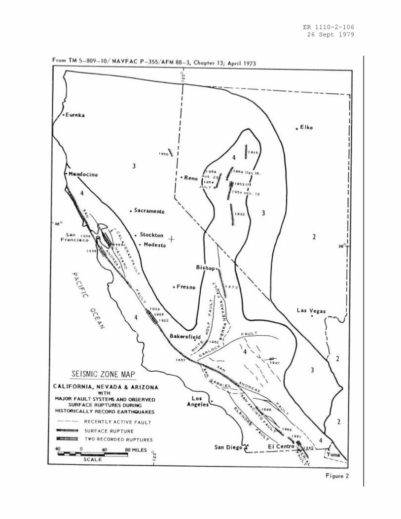
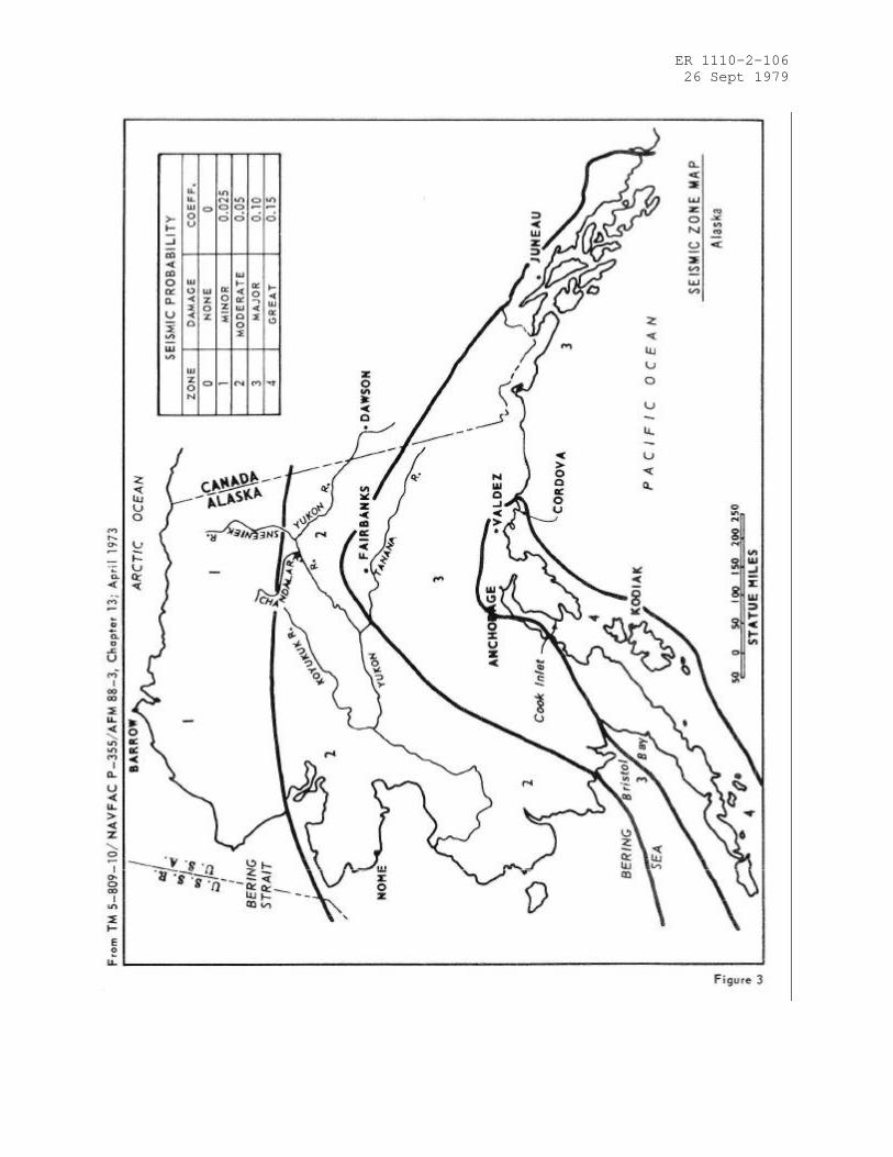
3.6.4. Seismic stability. An assessment should be made of the potential vulnerabilityof the dam to seismic events and a recommendation developed with regard to the needfor additional seismic investigation. In general, projects located in Seismic Zones 0,1 and 2 may be assumed to present no hazard from earthquake provided static stabilityconditions are satisfactory and conventional safety margins exist. Dams in Zones 3 and4 should, as a minimum, have on record suitable analyses made by conventionalequivalent static load methods. The seismic zones together with appropriatecoefficients for use in such analyses are shown in Figures 1 through 4. Boundary linesare approximate and in the event of doubt about the proper zone, the higher zoneshould be used. All high hazard category dams in Zone 4 and high hazard dams of thehydraulic fill type in Zone 3 should have a stability assessment based upon knowledgeof regional and local geology, engineering seismology, in situ properties of materialsand appropriate dynamic analytical and testing procedures. The assessment shouldinclude the possibility of physical displacement of the structures due to movementsalong active faults. Departure from this general guidance should be made whenever inthe judgment of the investigating engineer different seismic stability requirementsare warranted because of local geological conditions or other reasons.
ER 1110-2-10626 Sept 1979
CHAPTER 4 -- PHASE II INVESTIGATION
4.1. Purpose. The Phase II investigation will be supplementary to Phase I and shouldbe conducted when the results of the Phase I investigation indicate the need foradditional in-depth studies, investigations or analyses.
4.2. Scope. The Phase II investigation should include all additional studies,investigations and analyses necessary to evaluate the safety of the dam. Included, asrequired, will be additional visual inspections, measurements, foundation explorationand testing, materials testing, hydraulic and hydrologic analysis and structuralstability analyses.
4.3. Hydraulic and hydrologic analysis. Hydraulic and hydrologic capabilities shouldbe determined using the following criteria and procedures. Depending on the projectcharacteristics, either the spillway design flood peak inflow or the spillway designflood hydrograph should be the basis for determining the maximum water surfaceelevation and maximum outflow. If the operation or failure of upstream water controlprojects would have significant impact on peak flow or hydrograph analyses, the impactshould be assessed.
4.3.1. Maximum water surface based on SDF peak inflow. When the total projectdischarge capability at maximum pool exceeds the peak inflow of the recommended SDF,and operational constraints would not prevent such a release at controlled projects, areservoir routing is not required. The maximum discharge should be assumed equal tothe peak inflow of the spillway design flood. Flood volume is not controlling in thissituation and surcharge storage is either absent or is significant only to the extentthat it provides the head necessary to develop the release capability required.
4.3.1.1. Peak for 100-year flood. When the 100-year flood is applicable under theprovisions of Table 3 and data are available, the spillway design flood peak inflowmay be determined by use of "A Uniform Technique for Determining Flood Frequencies,"Water Resources Council (WRC), Hydrology Committee, Bulletin 15, December 1967. Flowfrequency information from regional analysis is generally preferred over singlestation results when available and appropriate. Rainfall-runoff techniques may benecessary when there are inadequate runoff data available to make a reasonableestimate of flow frequency.
4.3.1.2. Peak for PMF or fraction thereof. When either the Probable Maximum Flood peakor a fraction thereof is applicable under the provisions of Table 3, the unithydrograph -- infiltration loss technique is generally the most expeditious method ofcomputing the spillway design flood peak for most projects. This technique isdiscussed in the following paragraph.
4.3.2. Maximum water surface based on SDF hydrograph. Both peak and volume arerequired in this analysis. Where surcharge storage is significant, or where there isinsufficient discharge capability at maximum pool to pass the peak inflow of the SDF,considering all possible operational constraints, a flood hydrograph is required. Whenthere are upstream hazard areas that would be imperiled by fast rising reservoirslevels, SDF hydrographs should be routed to ascertain available time for warning andescape. Determination of probable maximum precipitation or 100-year precipitation,which ever is applicable, and unit hydrographs or runoff models will be required,followed by the determination of the PMF or 100-year flood. Conservative loss rates(significantly reduced by antecedent rainfall conditions where appropriate) should beestimated for computing the rainfall excess to be utilized with unit hydrographs.Rainfall values are usually arranged with gradually ascending and descending rateswith the maximum rate late in the storm. When applicable, conservatively high snowmeltrunoff rates and appropriate releases from upstream projects should be assumed. ThePMP may be obtained from National Weather Service (NWS) publications such asHydrometeorological Report (HMR) 33. Special NWS publications for particular areasshould be used when available. Rainfall for the 100-year frequency flood can beobtained from the NWS publication "Rainfall Frequency Atlas of the United States,"Technical Paper No. 40; Atlas 2, "Precipitation Frequency Atlas of Western UnitedStates;" or other NWS publications. The maximum water surface elevation and spillway

ER 1110-2-10626 Sept 1979
design flood outflow are then determined by routing the inflow hydrograph through thereservoir surcharge storage, assuming a starting water surface at the bottom ofsurcharge storage, or lower when appropriate. For projects where the bottom ofsurcharge space is not distinct, or the flood control storage space (exclusive ofsurcharge) is appreciable, it may be appropriate to select starting water surfaceelevations below the top of the flood control storage for routings. Conservativelyhigh starting levels should be estimated on the basis of hydrometeorologicalconditions reasonably characteristic for the region and flood release capability ofthe project. Necessary adjustment of reservoir storage capacity due to existing orfuture sediment or other encroachment may be approximated when accurate determinationof deposition is not practicable.
4.3.3. Acceptable procedures. Techniques for performing hydraulic and hydrologicanalyses are generally available from publications prepared by Federal agenciesinvolved in water resources development or textbooks written by the academiccommunity. Some of these procedures are rather sophisticated and require expensivecomputational equipment and large data banks. While results of such procedures aregenerally more reliable than simplified methods, their use is generally not warrantedin studies connected with this program unless they can be performed quickly andinexpensively. There may be situations where the more complex techniques have to beemployed to obtain reliable results; however, these cases will be exceptions ratherthan the rule. Whenever the acceptability of procedures is in question, the advice ofcompetent experts should be sought. Such expertise is generally available in the Corpsof Engineers, Bureau of Reclamation and Soil Conservation Service. Many otheragencies, educational facilities and private consultants can also provide expertadvice. Regardless of where such expertise is based, the qualification of thoseindividuals offering to provide it should be carefully examined and evaluated.
4.3.4. Freeboard allowances. Guidelines on specific minimum freeboard allowances arenot considered appropriate because of the many factors involved in suchdeterminations. The investigator will have to assess the critical parameters for eachproject and develop its minimum requirement. Many projects are reasonably safe withoutfreeboard allowance because they are designed for overtopping, or other factorsminimize possible overtopping. Conversely, freeboard allowances of several feet may benecessary to provide a safe condition. Parameters that should be considered includethe duration of high water levels in the reservoir during the design flood; theeffective wind fetch and reservoir depth available to support wave generation; theprobability of high wind speed occurring from a critical direction; the potential waverunup on the dam based on roughness and slope; and the ability of the dam to resisterosion from overtopping waves.
4.4 Stability investigations. The Phase II stability investigations should becompatible with the guidelines of this paragraph.
4.4.1 Foundation and material investigations. The scope of the foundation andmaterials investigation should be limited to obtaining the information required toanalyze the structural stability and to investigate any suspected condition whichwould adversely affect the safety of the dam. Such investigations may include boringsto obtain concrete, embankment, soil foundation, and bedrock samples; testingspecimens from these samples to determine the strength and elastic parameters of thematerials, including the soft seams, joints, fault gouge and expansive clays or othercritical materials in the foundation; determining the character of the bedrockincluding joints, bedding planes, fractures, faults, voids and caverns, and othergeological irregularities; and installing instruments for determining movements,strains, suspected excessive internal seepage pressures, seepage gradients and upliftforces. Special investigations may be necessary where suspect rock types such aslimestone, gypsum, salt, basalt, claystone, shales or others are involved infoundations or abutments in order to determine the extent of cavities, piping or otherdeficiencies in the rock foundation. A concrete core drilling program should beundertaken only when the existence of significant structural cracks is suspected orthe general qualitative condition of the concrete is in doubt. The tests of materialswill be necessary only where such data are lacking or are outdated.
ER 1110-2-10626 Sept 1979
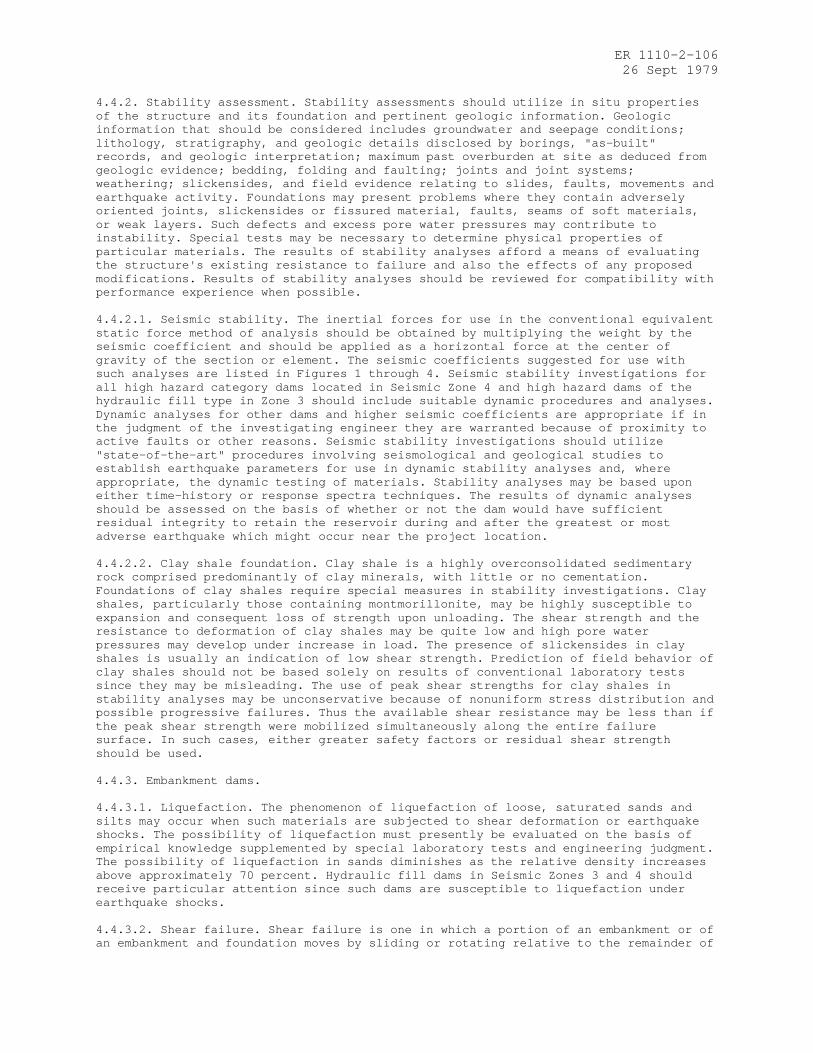
4.4.2. Stability assessment. Stability assessments should utilize in situ propertiesof the structure and its foundation and pertinent geologic information. Geologicinformation that should be considered includes groundwater and seepage conditions;lithology, stratigraphy, and geologic details disclosed by borings, "as-built"records, and geologic interpretation; maximum past overburden at site as deduced fromgeologic evidence; bedding, folding and faulting; joints and joint systems;weathering; slickensides, and field evidence relating to slides, faults, movements andearthquake activity. Foundations may present problems where they contain adverselyoriented joints, slickensides or fissured material, faults, seams of soft materials,or weak layers. Such defects and excess pore water pressures may contribute toinstability. Special tests may be necessary to determine physical properties ofparticular materials. The results of stability analyses afford a means of evaluatingthe structure's existing resistance to failure and also the effects of any proposedmodifications. Results of stability analyses should be reviewed for compatibility withperformance experience when possible.
4.4.2.1. Seismic stability. The inertial forces for use in the conventional equivalentstatic force method of analysis should be obtained by multiplying the weight by theseismic coefficient and should be applied as a horizontal force at the center ofgravity of the section or element. The seismic coefficients suggested for use withsuch analyses are listed in Figures 1 through 4. Seismic stability investigations forall high hazard category dams located in Seismic Zone 4 and high hazard dams of thehydraulic fill type in Zone 3 should include suitable dynamic procedures and analyses.Dynamic analyses for other dams and higher seismic coefficients are appropriate if inthe judgment of the investigating engineer they are warranted because of proximity toactive faults or other reasons. Seismic stability investigations should utilize"state-of-the-art" procedures involving seismological and geological studies toestablish earthquake parameters for use in dynamic stability analyses and, whereappropriate, the dynamic testing of materials. Stability analyses may be based uponeither time-history or response spectra techniques. The results of dynamic analysesshould be assessed on the basis of whether or not the dam would have sufficientresidual integrity to retain the reservoir during and after the greatest or mostadverse earthquake which might occur near the project location.
4.4.2.2. Clay shale foundation. Clay shale is a highly overconsolidated sedimentaryrock comprised predominantly of clay minerals, with little or no cementation.Foundations of clay shales require special measures in stability investigations. Clayshales, particularly those containing montmorillonite, may be highly susceptible toexpansion and consequent loss of strength upon unloading. The shear strength and theresistance to deformation of clay shales may be quite low and high pore waterpressures may develop under increase in load. The presence of slickensides in clayshales is usually an indication of low shear strength. Prediction of field behavior ofclay shales should not be based solely on results of conventional laboratory testssince they may be misleading. The use of peak shear strengths for clay shales instability analyses may be unconservative because of nonuniform stress distribution andpossible progressive failures. Thus the available shear resistance may be less than ifthe peak shear strength were mobilized simultaneously along the entire failuresurface. In such cases, either greater safety factors or residual shear strengthshould be used.
4.4.3. Embankment dams.
4.4.3.1. Liquefaction. The phenomenon of liquefaction of loose, saturated sands andsilts may occur when such materials are subjected to shear deformation or earthquakeshocks. The possibility of liquefaction must presently be evaluated on the basis ofempirical knowledge supplemented by special laboratory tests and engineering judgment.The possibility of liquefaction in sands diminishes as the relative density increasesabove approximately 70 percent. Hydraulic fill dams in Seismic Zones 3 and 4 shouldreceive particular attention since such dams are susceptible to liquefaction underearthquake shocks.
4.4.3.2. Shear failure. Shear failure is one in which a portion of an embankment or ofan embankment and foundation moves by sliding or rotating relative to the remainder of
ER 1110-2-10626 Sept 1979
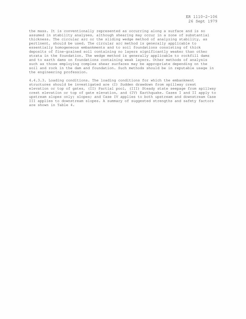
the mass. It is conventionally represented as occurring along a surface and is soassumed in stability analyses, although shearing may occur in a zone of substantialthickness. The circular arc or the sliding wedge method of analyzing stability, aspertinent, should be used. The circular arc method is generally applicable toessentially homogeneous embankments and to soil foundations consisting of thickdeposits of fine-grained soil containing no layers significantly weaker than otherstrata in the foundation. The wedge method is generally applicable to rockfill damsand to earth dams on foundations containing weak layers. Other methods of analysissuch as those employing complex shear surfaces may be appropriate depending on thesoil and rock in the dam and foundation. Such methods should be in reputable usage inthe engineering profession.
4.4.3.3. Loading conditions. The loading conditions for which the embankmentstructures should be investigated are (I) Sudden drawdown from spillway crestelevation or top of gates, (II) Partial pool, (III) Steady state seepage from spillwaycrest elevation or top of gate elevation, and (IV) Earthquake. Cases I and II apply toupstream slopes only; slopes; and Case IV applies to both upstream and downstream CaseIII applies to downstream slopes. A summary of suggested strengths and safety factorsare shown in Table 4.

ER 1110-2-10626 Sept 1979
TABLE 4
FACTORS OF SAFETY †
Case Loading ConditionFactor ofSafety Shear Strength †† Remarks
I Sudden drawdownfrom spillway crestor top of gates tominimum drawdownelevation.
1.2* Minimum compositeof R and S shearstrengths. SeeFigure 5.
Within the drawdown zonesubmerged unit weightsof materials are usedfor computing forcesresisting sliding andsaturated unit weightsare used from computingforces contributing tosliding.
II Partial pool withassumed horizontalsteady seepagesaturation.
1.5 (R+S)/2 for R < S
S for R > S
Composite ofintermediate envelope orR and S shear strengths.See Figure 6.
III Steady seepage fromspillway crest ortop of gates withKh/Kv = 9 assumed**
1.5 Same as Case II
IV Earthquake (CasesII and II withseismic loading)
1.0 *** See Figures 1 through 4for Seismic Coefficients
† Not applicable to embankments on clay shale foundation. Experience has indicatedspecial problems in determination of design shear strengths for clay shalefoundations and acceptable safety factors should be compatible with the confidencelevel in shear strength assumptions.
†† Other strength assumptions may be used if in common usage in the engineeringprofession.
* The safety factor should not be less than 1.5 when drawdown rate and pore waterpressure developed from flow nets are used in stability analyses.
**Kh/Kv is the ratio of horizontal to vertical permeability. A minimum value of 9 issuggested for use in compacted embankments and alluvial sediments.
***Use shear strength for case analyzed without earthquake. It is not necessary toanalyze sudden drawdown for earthquake loading. Shear strength tests areclassified according to the controlled drainage conditions maintained during thetest. R tests are those in which specimen drainage is allowed during consolidation(or swelling) under initial stress conditions, but specimen drainage is not allowedduring application of shearing stresses. S tests allow full drainage duringinitial stress application and shearing is at a slow rate so that complete specimendrainage is permitted during the complete test.

ER 1110-2-10626 Sept 1979
4.4.3.4. Safety factors. Safety factors for embankment dam stability studies should bebased on the ratio of available shear strength to developed shear strength, SD:
Where:C = Cohesion = Angle of internal friction = Normal stressF.S.= Factor of Safety
The factors of safety listed in Table 4 are recommended as minimum acceptable. Finalaccepted factors of safety should depend upon the degree of confidence theinvestigating engineer has in the engineering data available to him. The consequencesof a failure with respect to human life and property damage are importantconsiderations in establishing factors of safety for specific investigations.
4.4.3.5. Seepage failure. A critical uncontrolled underseepage or through seepagecondition that develops during a rising pool can quickly reduce a structure which wasstable under previous conditions, to a total structural failure. The visuallyconfirmed seepage conditions to be avoided are (1) the exit of the phreatic surface onthe downstream slope of the dam and (2) development of hydrostatic heads sufficient tocreate in the area downstream of the dam sand boils that erode materials by thephenomenon known as "piping" and (3) localized concentrations of seepage alongconduits or through pervious zones. The dams most susceptible to seepage problems arethose built of or on pervious materials of uniform fine particle size, with noprovisions for an internal drainage zone and/or no underseepage controls.
4.4.3.6. Seepage analyses. Review and modifications to original seepage designanalyses should consider conditions observed in the field inspection and piezometerinstrumentation. A seepage analysis should consider the permeability ratios resultingfrom natural deposition and from compaction placement of materials with appropriatevariation between horizontal and vertical permeability. An underseepage analysis ofthe embankment should provide a critical gradient factor of safety for the maximumhead condition of not less than 1.5 in the area downstream of the embankment.
Where:ic = Critical gradienti = Design gradientH = Uplift head at downstream toe of dam measured above tailwaterHc = The critical upliftDb = The thickness of the top impervious blanket at the downstream toe of the dam = The estimated saturated unit weight of the material in the top impervious blanket = The unit weight of water
Where a factor of safety less than 1.5 is obtained the provision of an underseepagecontrol system is indicated. The factor of safety of 1.5 is a recommended minimum andmay be adjusted by the responsible engineer based on the competence of the engineeringdata.
4.4.4. Concrete dams and appurtenant structures.
4.4.4.1. Requirements for stability. Concrete dams and structures appurtenant toembankment dams should be capable of resisting overturning, sliding and overstressingwith adequate factors of safety for normal and maximum loading conditions.

ER 1110-2-10626 Sept 1979
4.4.4.2. Loads. Loadings to be considered in stability analyses include the water loadon the upstream face of the dam; the weight of the structure; internal hydrostaticpressures (uplift) within the body of the dam, at the base of the dam and within thefoundation; earth and silt loads; ice pressure, seismic and thermal loads, and otherloads as applicable. Where tailwater or backwater exists on the downstream side of thestructure it should be considered, and assumed uplift pressures should be compatiblewith drainage provisions and uplift measurements if available. Where applicable, icepressure should be applied to the contact surface of the structure of normal poolelevation. A unit pressure of not more than 5,000 pounds per square foot should beused. Normally, ice thickness should not be assumed greater than two feet. Earthquakeforces should consist of the inertial forces due to the horizontal acceleration of thedam itself and hydrodynamic forces resulting from the reaction of the reservoir wateragainst the structure. Dynamic water pressures for use in a conventional methods ofanalysis may be computed by means of the "Westergaard Formula" using the parabolicapproximation (H.M. Westergaard, "Water Pressures on Dams During Earthquakes," Trans.,ASCE, Vol 98, 1933, pages 418-433), or similar method.
4.4.4.3. Stresses. The analysis of concrete stresses should be based on in situproperties of the concrete and foundation. Computed maximum compressive stresses fornormal operating conditions in the order of 1/3 or less of in situ strengths should besatisfactory. Tensile stresses in unreinforced concrete should be acceptable only inlocations where cracks will not adversely affect the overall performance and stabilityof the structure. Foundation stresses should be such as to provide adequate safetyagainst failure of the foundation material under all loading conditions.
4.4.4.4. Overturning. A gravity structure should be capable of resisting alloverturning forces. It can be considered safe against overturning if the resultant ofall combinations of horizontal and vertical forces, excluding earthquake forces,acting above any horizontal plane through the structure or at its base is locatedwithin the middle third of the section. When earthquake is included the resultantshould fall within the limits of the plane or base, and foundation pressures must beacceptable. When these requirements for location of the resultant are not satisfiedthe investigating engineer should assess the importance to stability of thedeviations.
4.4.4.5. Sliding. Sliding of concrete gravity structures and of abutment andfoundation rock masses for all types of concrete dams should be evaluated by theshear-friction resistance concept. The available sliding resistance is compared withthe driving force which tends to induce sliding to arrive at a sliding stabilitysafety factor. The investigation should be made along all potential sliding paths. Thecritical path is that plane or combination of planes which offers the leastresistance.

ER 1110-2-10626 Sept 1979
4.4.4.5.1. Sliding resistance. Sliding resistance is a function of the unit shearingstrength at no normal load (cohesion) and the angle of friction on a potential failuresurface. It is determined by computing the maximum horizontal driving force whichcould be resisted along the sliding path under investigation. The following generalformula is obtained from the principles of statics and may be derived by resolvingforces parallel and perpendicular to the sliding plane:
Where:
RR =Sliding Resistance (maximum horizontal driving force which can be resisted by thecritical path)
=Angle of internal friction of foundation material or, where applicable, angle ofsliding friction
V =Summation of vertical forces (including uplift)
C =Unit shearing strength at zero normal loading along potential failure plane
A =Area of potential failure plane developing unit shear strength "c"
=Angle between inclined plane and horizontal (positive for uphill sliding)
For sliding downhill the angle is negative and Equation (1) becomes:
When the plane of investigation is horizontal, and the angle á is zero andEquation (1) reduces to the following:
4.4.4.5.2. Downstream Resistance. When the base of a concrete structure is embedded inrock or the potential failure plane lies below the base, the passive resistance of thedownstream layer of rock may sometimes be utilized for sliding resistance. Rock thatmay be subjected to high velocity water scouring should not be used. The magnitude ofthe downstream resistance is the lesser of (a) the shearing resistance along thecontinuation of the potential sliding plane until it daylights or (b) the resistanceavailable from the downstream rock wedge along an inclined plane. The theoreticalresistance offered by the passive wedge can be computed by a formula equivalent toformula (3):
Where:
Pp = Passive resistance of rock wedge W = Weight (buoyant weight if applicable) of downstream rock wedge above inclined
plane of resistance, plus any superimposed loads = Angle of internal friction or, if applicable, angle of sliding friction = Angle between inclined failure plane and horizontalc = Unit shearing strength at zero normal load along failure planeA = Area of inclined plane of resistance

ER 1110-2-10626 Sept 1979
When considering cross-bed shear through a relatively shallow, competent rock strut,without adverse jointing or faulting, W and á may be taken at zero and 45°,respectively, and an estimate of passive wedge resistance per unit width obtained bythe following equation:
Where:D=Thickness of the rock strut
4.4.4.5.3. Safety factor. The shear-friction safety factor is obtained by dividing theresistance RR by H, the summation of horizontal service loads to be applied to thestructure:
When the downstream passive wedge contributes to the sliding resistance, the shearfriction safety factor formula becomes:
The above direct superimposition of passive wedge resistance is valid only if shearingrigidities of the foundation components are similar. Also, the compressive strengthand buckling resistance of the downstream rock layer must be sufficient to develop thewedge resistance. For example, a foundation with closely spaced, near horizontal,relatively weak seams might not contain sufficient buckling strength to develop themagnitude of wedge resistance computed from the cross-bed shear strength. In this casewedge resistance should not be assumed without resorting to special treatment (such asinstalling foundation anchors). Computed sliding safety factors approximating 3 ormore for all loading conditions without earthquake, and 1.5 including earthquake,should indicate satisfactory stability, depending upon the reliability of the strengthparameters used in the analyses. In some cases when the results of comprehensivefoundation studies are available, smaller safety factors may be acceptable. Theselection of shear strength parameters should be fully substantiated. The bases forany assumptions; the results of applicable testing, studies and investigations; andall pre-existing, pertinent data should be reported and evaluated.

ER 1110-2-10626 Sept 1979
CHAPTER 5 -- REPORTS
5.1. General. This chapter outlines the procedures for reporting the results of thetechnical investigations. Hazardous conditions should be reported immediately upondetection to the owner of the dam, the Governor of the State in which the dam islocated and the appropriate regulatory agency without delay for preparation of theformal report.
5.2. Preparation of report. A formal report should be prepared for each daminvestigated for submission to the regulatory agency and the owner of the dam. Eachreport should contain the information indicated in the following paragraphs. Thesignature and registration identification of the professional engineer who directedthe investigation and who was responsible for evaluation of the dam should be includedin the report.
5.2.1. Phase I reports. Phase I reports should contain the following information:
5.2.1.1. Description of dam including regional vicinity map showing location andplans, elevations and sections showing the essential project features and the size andhazard potential classifications.
5.2.1.2. Summary of existing engineering data, including geologic maps andinformation.
5.2.1.3. Results of the visual inspection of each project feature includingphotographs and drawings to minimize descriptions.
5.2.1.4. Evaluation of operational adequacy of the reservoir regulation plan andmaintenance of the dam and operating facilities and features that pertain to thesafety of the dam.
5.2.1.5. Description of any warning system in effect.
5.2.1.6. Evaluation of the hydraulic and hydrologic assumptions and structuralstability.
5.2.1.7. An assessment of the general condition of the dam with respect to safetybased upon the findings of the visual inspection and review of engineering data. Wheredata on the original design indicate significant departure from or non-conformancewith guidelines contained herein, the engineer-in-charge of the investigation willgive his opinion of the significance, with regard to safety, of such factors. Anyadditional studies, investigations and analyses considered essential to assessment ofthe safety of the dam should be listed, together with an opinion about the urgency ofsuch additional work.
5.2.1.8. Indicate alternative possible remedial measures or revisions in operating andmaintenance procedures which may (subject to further evaluation) correct deficienciesand hazardous conditions found during the investigation.
5.2.2. Phase II reports. Phase II reports should describe the detailed investigationsand should supplement Phase I reports. They should contain the following information:
5.2.2.1. Summary of additional engineering data obtained to determine the hydraulicand hydrologic capabilities and/or structural stability.
5.2.2.2. Results of all additional studies, investigations, and analyses performed.
5.2.2.3. Technical assessment of dam safety including deficiencies and hazardousconditions found to exist.
5.2.2.4. Indicate alternative possible remedial measures or revision in maintenanceand operating procedures which may (subject to further evaluation) correctdeficiencies and hazardous conditions found during the investigation.

ER 1110-2-10626 Sept 1979
ER 1110-2-10626 Sept 1979
ER 1110-2-10626 Sept 1979

ER 1110-2-10626 Sept 1979

ER 1110-2-10626 Sept 1979

ER 1110-2-10626 Sept 1979

ER 1110-2-10626 Sept 1979
APPENDIX I
ENGINEERING DATA
This appendix lists engineering data which should be collected from project recordsand, to the extent available, included in the Phase I investigation report. The listis intended to serve as a checklist and not to establish rigid data requirements. Sucha compilation should also facilitate future inspections and investigations. Only datareadily available will be included in Phase I reports, but data lacking and deemednecessary for an adequate safety evaluation should be identified.
1. General Project Data
a. Regional Vicinity Map showing the location of the dam, the upstream drainage areaand the downstream area subject to potential damage due to failure of the dam andmisoperation or failure of the operating equipment.
b. As-Built Drawings indicating plans, elevations and sections of the dam andappurtenant structures including the details of the discharge facilities such asoutlet works, limited service and emergency spillways, flashboards, fuse plugs andoperating equipment.
2. Hydrologic and Hydraulic Data including the following:
a. Drainage area and basin runoff characteristics (indicating pending changes).
b. Elevation of top of conservation pool or normal upper retention water surfaceelevation, as applicable (base level of any flood impoundment).
c. Storage capacity including dead or inactive storage, corresponding to top ofconservation or normal upper retention level (cumulative, excluding flood control andsurcharge storage).
d. Elevation of the top of flood control pool.
e. Storage capacity of flood control zone (incremental).
f. Elevation of maximum design pool (corresponding to top of surcharge storage orspillway design flood).
g. Storage capacity of surcharge zone (incremental, above top of flood control poolor, above normal upper retention level if flood control space not provided).
h. Height of freeboard (distance between maximum design flood water surface and top ofdam).
i. Elevation of top of dam (lowest point of embankment or non-overflow structure).
j. Elevation of crest, type, width, crest length and location of spillways (number,size and type of gates if controlled).
k. Type, location, entrance and exit inverts of outlet works and emergency drawdownfacilities (number, size and shape of conduits and gates, including penstocks andsluices').
l. Location, crest elevation, description of invert and abutments (concrete, rock,grass, earth) and length of limited service and emer%ency spillways.
m. Location and description of flashboards and fuse plugs, including hydraulic head(pool elevation) and other conditions required for breaching, along with the assumedresults of breaching.

ER 1110-2-10626 Sept 1979
n. Location and top elevation of dikes and floodwalls (overflow and non-overflow)affected by reservoir. Include information on low reaches of reservoir rim.
o. Type, location, observations and records of hydrometeorological gages appurtenantto the project.
p. Maximum non-damaging discharge, or negligible damage rate, at potential damagelocations downstream.
3. Foundation Data and Geological Features including logs of borings, geological maps,profiles and cross sections, and reports of foundation treatment.
4. Properties of Embankments and Foundation Materials including results of laboratorytests, field permeability tests, construction control tests, and assumed designproperties for materials.
5. Concrete Properties including the source and type of aggregate, cement used, mixdesign a and the results of testing during construction.
6. Electrical and Mechanical Equipment type and rating of normal and emergency powersupplies, hoists, cranes, valves and valve operator, control and alarm systems andother electrical and mechanical equipment and systems that could affect the safeoperation of the dam.
7. Construction History including diversion scheme, construction sequence, pertinentconstruction problems, alterations, modifications and maintenance repairs.
8. Water Control Plan including regulation plan under normal conditions and duringflood events or other emergency conditions. The availability of dam tenders, means ofcommunication between dam tenders and authority supervising water control, and methodof gate operation (manual, automatic, or remote control) should be included. Floodwarning systems should be described in sufficient detail to enable assessment of theirreduction in the flood hazard potential.
9. Operation Record.
a. Summary of past major flood events including any experiences that presented aserious threat to the safety of the project or to human life or property. The criticalproject feature, date and duration of event, causative factor, peak inflow andoutflow, maximum elevation of water surface, wind and wave factors if significant,issuance of alert or evacuation warnings and adequacy of project feature involvedshould be included in the summary of past experience of serious threat to the safetyof the project.
b. Records of performance observations including instrumentation records.
c. List of any known deficiencies that pose a threat to the safety of the dam or tohuman life or property.
d. History of previous failures or deficiencies and pending remedial measures forcorrecting known deficiencies and the schedule for accomplishing remedial measuresshould be indicated.
10. Earthquake History including a summary of the seismic data of significant recordedearthquakes in the vicinity of the dam and information on major damage in the vicinityof the dam from both recorded and unrecorded earthquakes. Regional geologic maps andother documents showing fault locations should be collected.
11. Inspection History including the results of the last safety inspection, theorganization that performed the inspection, the date inspection performed and theauthority for conducting the inspection.
12. Principal Design Assumptions and Analyses.

ER 1110-2-10626 Sept 1979
a. Hydrologic and Hydraulic Determinations.
(1) Quantity, time and area distribution, and reference source of depth-area-duration data of spillway design storm precipitation (point precipitation ifapplicable).
(2) Maximum design flood inflow hydrograph including loss rates (initial andaverage for design flood conditions) and time of runoff concentration of reservoirwatershed (peak inflow only when applicable).
(3) Maximum design flood outflow hydrograph (maximum outflow only whenapplicable).
(4) Discharge-frequency relationship, preferably at damsite, includingestimated frequency of spillway design flood for small dams, when appropriate.
(5) Reservoir area and storage capacity versus water surface elevation (tableor curves).
(6) Rating curves (free flow and partial gate openings) for all dischargefacilities contributing to the maximum design flood outflow hydrograph. Also acomposite-rating of all contributing facilities, if appropriate.
(7) Tailwater rating curve immediately below damsite including elevationcorresponding to maximum design flood discharge and approximate nondamaging channelcapacity.
(8) Hydrologic map of watershed above damsite including reservoir area,watercourse, elevation contours,, and principal stream-flow and precipitation gagingstations.
b. Stability and Stress Analysis of the dam, spillway and appurtenant structures andfeatures including the assumed properties of materials and all pertinent appliedloads.
c. Seepage and Settlement Analyses. The determination of distribution,, direction andmagnitude of seepage forces and the design and construction measures for theircontrol. Settlement estimates and steps adopted to compensate for total settlement andto minimize differential settlements.
ER 1110-2-10626 Sept 1979
APPENDIX II
INSPECTION ITEMS
This appendix provides guidance for performing field inspections and may serve as thebasis for developing a detailed checklist for each dam.
I. Concrete Structures in General.
a. Concrete Surfaces. The condition of the concrete surfaces should be examined toevaluate the deterioration and continuing serviceability of the concrete. Descriptionsof concrete conditions should conform with the appendix to "Guide for Making aCondition Survey of Concrete in Service", American Concrete Institute (ACI) Journal,Proceedings Vol. 65, No. 11, November 1968, page 905-918.
b. Structural Cracking. Concrete structures should be examined for structural crackingresulting from overstress due to applied loads, shrinkage and temperature effects ordifferential movements.
c. Movement Horizontal and Vertical Alignment. Concrete structures should be examinedfor evidence of any abnormal settlements, heaving, deflections, or lateral movements.
d. Junctions. The conditions at the junctions of the structure with abutments orembankments should be determined.
e. Drains Foundation, Joint, Face. All drains should be examined to determine thatthey are capable of performing their design function.
f. Water Passages. All water passages and other concrete surfaces subject t6 runningwater should be examined for erosion, cavitation, obstructions, leakage or significantstructural cracks.
g. Seepage or Leakage. The faces, abutments and toes of the concrete structures shouldbe examined for evidence of seepage or abnormal leakage, and records of flow ofdownstream springs reviewed for variation with reservoir pool level. The sources ofseepage should be determined if possible.
h. Monolith Joints Construction Joints. All monolith and construction joints should beexamined to determine the condition of the joint and filler material, any movement ofjoints, or any indication of distress or leakage.
i. Foundation. Foundation should be examined for damage or possible undermining of thedownstream toe.
j. Abutments. The abutments should be examined for sign of instability or excessiveweathering.
2. Embankment Structures.
a. Settlement. The embankments and downstream toe areas should be examined for anyevidence of localized or overall settlement, depressions or sink holes.
b. Slope Stability. Embankment slopes should be examined for irregularities inalignment and variances from smooth uniform slopes, unusual changes from originalcrest alignment and elevation, evidence of movement at or beyond the toe, and surfacecracks which indicate movement.
c. Seepage. The downstream face of abutments, embankment slopes and toes, embankmentstructure contacts, and the downstream valley areas should be examined for evidence ofexisting or past seepage. The sources of seepage should be investigated to determinecause and potential severity to dam safety under all operating conditions. Thepresence of animal burrows and tree growth on slopes which might cause detrimentalseepage should be examined.

ER 1110-2-10626 Sept 1979
d. Drainage Systems. All drainage systems should be examined to determine whether thesystems can freely pass discharge and that the discharge water is not carryingembankment or foundation material. Systems used to monitor drainage should be examinedto assure they are operational and functioning properly.
e. Slope Protection. The slope protection should be examined for erosion-formedgullies and wave-formed notches and benches that 'have reduced the embankment cross-section or exposed less wave resistant materials. The adequacy of slope protectionagainst waves, currents, and surface runoff that may occur at the site should beevaluated. The condition of vegetative cover should be evaluated where pertinent.
3. Spillway Structures. Examination should be made of the structures and featuresincluding bulkheads, flashboards, and fuse plugs of all service and auxiliaryspillways which serve as principal or emergency spillways for any condition which mayimpose operational constraints on the functioning of the spillway.
a. Control Gates and Operating Machinery. The structural members, connections, hoists,cables and operating machinery and the adequacy of normal and emergency power suppliesshould be examined and tested to determine the structural integrity and verify theoperational adequacy of the equipment. Where cranes are intended to be used forhandling gates and bulkheads, the availability, capacity and condition of the cranesand lifting beams should be investigated. Operation of control systems and protectiveand alarm devices such as limit switches, sump high water alarms and drainage pumpsshould be investigated.
b. Unlined Saddle Spillways. Unlined saddle spillways should be examined for evidenceof erosion and any conditions which may impose constraints on the functioning of thespillway. The ability of the spillway to resist erosion due to operation and thepotential hazard to the safety of the dam from such operation should be determined.
c. Approach and Outlet Channels. The approach and outlet channels should be examinedfor any conditions which may impose constraints on the functioning of the spillway andpresent a potential hazard to the safety of the dam.
d. Stilling Basin, (Energy Dissipators). Stilling basins including baffles, flipbuckets or other energy dissipators should be examined for any conditions which maypose constraints on the ability of the stilling basin to prevent downstream scour orerosion which may create or present a potential hazard to the safety of the dam. Theexisting condition of the channel downstream of the stilling basin should bedetermined.
4. Outlet Works. The outlet works examination should include all structures andfeatures designed to release reservoir water below the spillway crest through oraround the dam.
a. Intake Structure. The structure and all features should be examined for anyconditions which may impose operational constraints on the outlet works. Entrances tointake structure should be examined for conditions such as silt or debris accumulationwhich may reduce the discharge capabilities of the outlet works.
b. Operating and Emergency Control Gates. The structural members, connections, guides,hoists, cables and operating machinery including the adequacy of normal and emergencypower supplies should be examined and tested to determine the structural integrity andverify the operational adequacy of the operating and emergency gates, valves,bulkheads, and other equipment.
c. Conduits, Sluices, Water Passages, Etc. The interior surfaces of conduits should beexamined for erosion, corrosion, cavitation, cracks, joint separation and leakage atcracks or joints.
d. Stilling Basin (Energy Dissipator). The stilling basin or other energy dissipatershould be examined for conditions which may impose any constraints on the ability of

ER 1110-2-10626 Sept 1979
the stilling basin to prevent downstream scour or erosion which may create or presenta potential hazard to the safety of the dam. The existing condition of the channeldownstream of the stilling basin should be determined by soundings.
e. Approach and Outlet Channels. The approach and outlet channels should be examinedfor any conditions which may impose constraints on the functioning of the dischargefacilities of the outlet works, or present a hazard to the safety of the dam.
f. Drawdown Facilities. Facilities provided for drawdown of the reservoir to avertimpending failure of the dam or to facilitate repairs in the event of stability orfoundation problems should be examined for any conditions which may impose constraintson their functioning as planned.
5. Safety and Performance Instrumentation. Instruments which have been installed tomeasure behavior of the structures should be examined for proper functioning. Theavailable records and readings of installed instruments should be reviewed to detectany unusual performance of the instruments or evidence of unusual performance ordistress of the structure, The adequacy of the installed instrumentation to measurethe performance and safety of the dam should be determined.
a. Headwater and Tailwater Gages. The existing records of the headwater and tailwatergages should be examined to determine the relationship between other instrumentationmeasurements such as stream flow, uplift pressures, alignment, and drainage systemdischarge with the upper and lower water surface elevations.
b. Horizontal and Vertical Alignment instrumentation (Concrete Structures). Theexisting records of alignment and elevation surveys and measurements frominclinometers, inverted plumb bobs, gage points acr6ss cracks and joints, or otherdevices should be examined to determine any change from the original position of thestructures.
c. Horizontal and Vertical Movement, Consolidation, and Pore-Water PressureInstrumentation (Embankment Structures). The existing records of measurements fromsettlement plates or gages, surface reference marks, slope indicators and otherdevices should be examined to determine the movement history of the embankment.Existing piezometer measurements should be examined to determine if the pore-waterpressures in the embankment and foundation would under given conditions impair thesafety of the dam.
d. Uplift Instrumentation. The existing records of uplift measurements should beexamined to determine if the uplift pressures for the maximum pool would impair thesafety of the dam.
e. Drainage System Instrumentation. The existing records of measurements of thedrainage system flow should be examined to establish the normal relationship betweenpool elevations and discharge quantities and any changes that have occurred in thisrelationship during the history of the project.
f. Seismic Instrumentation, The existing records of seismic instrumentation should beexamined to determine the seismic activity in the area and the response of thestructures to past earthquakes.
6. Reservoir. The following features of the reservoir should be examined to determineto what extent the water impounded by the dam would constitute a danger to the safetyof the dam or a hazard to human life or property.
a. Shore line. The land forms around the reservoir should be examined for indicationsof major active or inactive landslide areas and to determine susceptibility of bedrockstratigraphy to massive landslides of sufficient magnitude to significantly reducereservoir capacity or create waves that might overtop the dam.
b. Sedimentation. The reservoir and drainage area should be examined for excessivesedimentation or recent developments in the drainage basin which could cause a sudden

ER 1110-2-10626 Sept 1979
increase in sediment load thereby reducing the reservoir capacity with attendantincrease in maximum outflow and maximum pool elevation.
c. Potential Upstream Hazard Areas. The reservoir area should be examined for featuressubject to potential backwater flooding resulting in loss of human life or property atreservoir levels up to the maximum water storage capacity including any surchargestorage.
d. Watershed Runoff Potential. The drainage basin should be examined for any extensivealterations to the surface of the drainage basin such as changed agriculturepractices, timber clearing, railroad or highway construction or real estatedevelopments that might extensively affect the runoff characteristics. Upstreamprojects that could have impact on the safety of the dam should be identified.
7. Downstream Channel. The channel immediately downstream of the dam should beexamined for conditions which might impose any constraints on the operation of the damor present any hazards to the safety of the dam. Development of the potential floodedarea downstream of the dam should be assessed for compatibility with the hazardclassification.
8. Operation and Maintenance Features.
a. Reservoir Regulation Plan. The actual practices in regulating the reservoi7r anddischarges under normal and emergency conditions should be examined to determine ifthey comply with the designed reservoir regulation plan and to assure that they do notconstitute a danger to the safety of the dam or to human life or property.
b. Maintenance. The maintenance of the operating facilities and features that pertainto the safety of the dam should be examined to determine the adequacy and quality ofthe maintenance procedures followed in maintaining the dam and facilities in safeoperating condition.

ER 1110-2-10626 Sept 1979
Be it enacted by the Senate and the House of Representatives of the United States of America in Congress,assembled, That the term “dam” as used in this Act means any artificial barrier, including appurtenant works, whichimpounds or diverts water, and which (1) is twenty-five feet or more in height from the natural bed of the stream orwatercourse measured at the downstream toe of the barrier, or from the lowest elevation of the outside limit of thebarrier, if it is not across a stream channel or watercourse, to the maximum water storage elevation or (2) has animpounding capacity at maximum water storage elevation of fifty acre-feet or more. This Act does not apply to anysuch barrier which is not in excess of six feet in height, regardless of storage capacity or which has a storagecapacity at maximum water storage elevation not in excess of fifteen acre-feet, regardless of height.
Sec. 2. As soon as practicable, the Secretary of the Army, acting through the Chief of Engineers, shall carry out anational program of inspection of dams for the purpose of protecting human life and property. All dams in theUnited States shall be inspected by the Secretary except (1) dams under the jurisdiction of the Bureau ofReclamation, the Tennessee Valley Authority, or the International Boundary and Water Commission, (2) damswhich have been constructed pursuant to licenses issued under the authority of the Federal Power Act, (3) damswhich have been inspected within the twelve-month period immediately prior to the enactment of this Act by a StateAgency and which the Governor of such State requests be excluded from inspection, and (4) dams which theSecretary of the, Army determines do not pose any threat to human life or property. The Secretary may inspect damswhich have been licensed under the Federal Power Act upon request of the Federal Power Commission and damsunder the jurisdiction of the International Boundary and Water Commission upon request of such Commission.
Sec. 3. As soon as practicable after inspection of a dam, the Secretary shall notify the Governor of the State in whichsuch dam is located the results of such investigation. The Secretary shall immediately notify the Governor of anyhazardous conditions found during an inspection. The Secretary shall provide advice to the Governor, upon request,relating to timely remedial measures necessary to mitigate or obviate any hazardous conditions found during aninspection.
Sec. 4. For the purpose of determining whether a dam (including the waters impounded by such dam) constitutes adanger to human life or property, the Secretary shall take into consideration the possibility that the dam might beendangered by overtopping, seepage, settlement, erosion, sediment, cracking, earth movement, earthquakes, failureof bulkheads, flashboard, gates on conduits, or other- conditions which exist or which might occur in any area in thevicinity of the darn.
Sec. 5. The Secretary shall report to the Congress on or before July 1, 1974, on his activities under the Act, whichreport shall include, but not be limited to-
(1) an inventory of all dams located in the United States;(2) a review of each inspection made, the recommendations furnished to the Governor of the State in which
such dam is located and information as to the implementation of such recommendation;(3) recommendations for a comprehensive national program for the inspection, and regulation for safety
purpose of dams of the Nation, and the respective responsibilities which should be assumed by Federal, State, andlocal governments and by public and private interests.
Sec. 6. Nothing contained in this Act and no action or failure to act under this Act sliall be construed (1) to createany liability in the United States or its officers or employees for the recovery of damages caused by such action orfailure to act; or (2) to relieve an owner or operator of a dam of the legal duties, obligations, or liabilities incident tothe ownership or operation of the, dam.
Approved August 8. 1972.
Public Law 92-36792nd Congress, H. R. 15951
August 8, 1972
An Act
To authorize the Secretary of the Army to undertake a national program ofinspection of dams