eriks sealing technology
TRANSCRIPT

ERIKS Sealing Technology Engineered Polymer Solutions for Oil & Gas Applications

2
Oil and Gas applications present the most extreme conditions in which seals are expected to operate. Mechanical, thermo-chemical and fluid phase conditions must be accommodated to maintain the integrity of the seal in these, often safety critical, uses.Richard Curtis Technical Manager ERIKS Sealing Technology
Contents
Dynamic SealsDynamic seal designs demand the use of
compounds with tailored physical properties able to withstand the stresses resultant from their operation

3
ContentsInTRODuCTIOn 04LOGISTICS 05
TEChnICaL 06Test and Validation 06
Pressure Guidelines 07
Groove Design 08
MaTERIaLS 09Technology Centre 09
Elastomers 10
Compounds 16
Thermoplastics 18
Chemical Compatibility Chart 20
Explosive Decompression 22
appLICaTIOnS 25
pRODuCTS 28O-ring 28
Vulc-O-ring 30
Back-up Rings 31
T-seal 34
S-seal 36
Energised Lip Seals 37
Cap Seals 38
Spring Energised Seal 44
Metal Face Seals 46
Exclusion Devices / Wiper Rings 50
Machined Wear Ring 52
aDDITIOnaL pRODuCTS & SERvICES 58V-packing 58
Lip Seals for Pipeline Closures 58
Moulded Products, Gaskets, Valves 59
All information in this documentation has been compiled with care to ensure accuracy. Despite this we can bear no liability for error and/or changes in legislation that may affect content. Recommendations are intended as guidelines only, for further information and technical assistance, please consult your ERIKS representative.
Viton and Kalrez are trademarks of DuPont, Aflas is a trademark of Asahi Glass, Elgiloy is a trademark of Elgiloy Ltd, Hastelloy is a trademark of Haynes International Inc.

4
Comprehensive Sealing
Introduction
With locations and dedicated application engineers based at all of the major global oil and gas industry hubs, ERIKS Sealing Technology is an ideal partner to service your sealing requirements.
Boasting cutting edge technology
centres in the UK and USA, ERIKS
Sealing Technology operates at
the forefront of material science,
developing new and tightly
controlled, qualified compounds.
Experienced application engineers draw
upon in-depth technical knowledge
to ensure that the optimal seal is
impartially specified for your application;
whether this is a standard product from
our premium manufacturers, or as a
bespoke solution tailored to your needs.
ERIKS design teams work closely
with our material scientists to produce
accurate materials data upon which our
non-linear finite element analyses are
based, to minimise design iterations in
successfully satisfying your application.
We use the latest 3D CAD to
capture design intent, which is
verified using our contact and
non-contact CMM equipment.
Full traceability of product and
batch data per NORSOK M710
requirements is available. We
hold ISO 9001:2008 certification
across both of the UK sealing core
competence centres and throughout
our FPAL accredited distribution
network, for your peace of mind.
We work closely with premium
manufacturers to provide market
specific stock profiles and can offer
logistical solutions including direct
supply, managed inventory, or on-
site integrated supply; available via
our extensive branch network.
O-rings manufactured from our
speciality polymers are also available
as components in both our Econ®
and other valves via Econosto.
ERIKS’ focus on five core activities: n Sealing technology
n Power transmission, including
electromechanical services and
condition monitoring
n Flow technology
n Industrial plastics
n Tools and maintenance products
These products are supported by
advanced technical and logistics services
that form the link between our know-how
and your reliability.
5
Stock availability SupportAs Europe’s largest stockholder of sealing
and associated products, you are assured
of the highest levels of availability to keep
your operation working.
We hold extensive stocks of O-rings in
elastomer compounds suitable for both
general purpose and high pressure
operation, that may be despatched
same-day to meet your requirements.
O-rings are available in AS568,
BS1806, BS4518 and ISO 3601, sizes
together with Hydraulic Seals, Back-up
Rings, Metal Face Seals, Mechanical
and Rotary Seals.
Customer specific stock holding is our
speciality. This maintains continuity
of supply, including specific qualified
products that we would not otherwise
hold. Our advanced logistics software
helps us optimise customer specific
stock to maximise availability yet
minimise your capital exposure.
n Dedicated office based technical
support staff and customer service
n Field based Sealing Technology
application engineers and specialists
n Excellent technical support from
skilled research and development
engineers
n 24-hour call out service available
Logistics
Our global network of Service Centres includes 70 UK locations
and 25 UK Repair Workshops. This ensures our product and
application know how is readily available, to provide support 24/7.
Our local teams have a direct line to all the technical support you
may need along with visibility of our own stocks and those of our
supply partners.
Global network - Local to you

6 Technical
In an environment dedicated to innovation
and free thought, our highly talented
design team work with the latest 3D
CAD tools to capture design intent with
your teams. This technology proves an
invaluable tool in communicating and
developing conceptual solutions involving
co-engineering partnerships, as we
can share 3D data in many standard
formats including IGES and STEP.
Comprehensive change control and
configuration management techniques
are used to ensure that the design
intent is fully embodied into the finished
product; with our combined visual and
CMM dimensional inspection system
being programmed from the original 3D
CAD model.
Finite Element analysis (FEa)To improve design integrity and
efficiency, we use FEA as a
mathematical technique to predict:
deflection (strain), stress, reaction force
and contact pressure. These are based
on dimensional information, physical
constraints and material properties.
Our Materials Technology Centre
can generate temperature specific,
validated, hyper-elastic material models,
on which to base these analyses. FEA
then allows our engineers to rapidly
iterate to optimal design solutions,
minimising product development time
and cost, reducing time to market.
Test and validation
High volume - High pressure gas:
10,000psi gaseous media
Hydro-testing up to pressure class 300
Hydro-testing up to pressure class 2500
Nitrogen Gas (N2) Test media system –
Ambient temperature gas testing up to pressure class 2500
Low volume – high pressure to 25000psi
Low pressure valve seat and seal testing
Testing:In house application capabilities include:

7
pressure Guidelines
At high pressures, above 10MPa, it is typical to use an O-ring in conjunction with either one or two Back-up rings, or to use high
performance seal designs such as T-Seals.
Har
dnes
s (I
HR
D)
2 7 12 17
Modulus (MPa)
90°
50°
60°
70°
80°
GeneralPurpose
ExtremePressure
Very LowPressure
Rules to Determine Elastomeric Material SelectionLow hardness and low modulus elastomers complement lower
pressure sealing applications. Extreme pressure applications
require materials that are robust, with high modulus and
high hardness.
O-Ring Pressure Capability
Radial Extrusion Gap (mm)
ElastomerHardness
70° IRHD
80° IRHD
90° IRHD
Diff
eren
tial P
ress
ure
(MP
a)
0
5
10
15
20
25
30
40
50
45
35
0.05 0.1 0.15 0.2 0.25 0.3
O-ring pressure Capability
Contact ERIKS for assistance in selecting the correct solution for your high pressure application.
Sealing of extreme pressure applications typically requires robust high modulus, high hardness materials. On the contrary,
elastomers with a reduced hardness and lower modulus are more compliant and complement lower pressure sealing applications.
It is normal practice to specify elastomers with a high hardness for high pressure applications. With the vast array of elastomeric
compounds and formulations available today, it is possible to utilise materials with a relatively low hardness and relatively high modulus.
8 Technical
Groove StandardsAs experts in seal design we recognise that there are a
number of international standards used to specify O-Rings
into grooves.
AS5857 and AS4716 detail grooves suitable for use
with AS568 O-Rings for static and dynamic applications,
respectively. All three standards are governed by the US
Society of Automotive Engineers and are available from www.
sae.org. AS4716 supersedes the popular MIL-G-5514 for
dynamic applications.
BS1806 and BS4518 are the British Standards for Imperial
and Metric sizes respectively. BS1806 has now been
withdrawn and has been replaced by ISO3601, however the
recommended groove dimensions differ between the two.
ISO3601 is a comprehensive standard for imperial sizes.
However care should be taken when specifying dynamic
locations as use of this standard may result in unnecessary
machining and AS4716 should be considered in its place.
Groove Design ConsiderationsCompression (Squeeze) – Compression is applied to an
O-ring, which creates an initial seal. As differential pressure
increases this is transmitted by the visco-elastic material, with
the normal force increasing with pressure, maintaining the
seal. There is no single correct initial percentage compression,
as this will vary by application. Typically nominal compression
levels are:
Face seals - 25%
Static piston / rod seals – 15%
(Lower at large cross section, higher at small cross section,
governed by installation force)
Dynamic piston / rod seals – 12%
Increased squeeze may be used to increase high pressure
performance; standard grooves should be used per the above
except for pressures above 4000psi or where RGD (see
below) will be seen. For advice on groove optimisation for
such applications please contact our technical department.
Groove Design
Groove fill (Gland Occupancy)To ensure pressure energisation of the seal for high pressure
operation the O-ring should not reach 100% gland occupancy.
Typical nominal occupancy levels would be 75% and with
the standards taking account of differential rates of thermal
expansion, chemical swell and tolerance stack-up.
StretchO-rings are typically stretched into piston grooves to
overcome tolerance stack-up and ensure correct assembly.
Rod applications typically interfere on the outside diameter,
although stretch may be applied this is always in a constrained
state.
Design for Rapid Gas Decompression (Explosive Decompression)The adverse effects of rapid gas decompression may be
mitigated through both correct compound selection and
appropriate mechanical design. To allow dissolved gasses
to rapidly permeate out from the seal, smaller cross section
O-rings should be used. Use of 200 series, 3.53mm cross
section, O-rings is typical. High groove fill and decreased
squeeze may be used to minimise principal stresses generated
during Rapid Gas Decompression (RGD) and hence increase
resistance. For advice on groove optimisation for such
applications please contact our technical department.

9
Material Technology CentreERIKS Material Technology Centre is
a testimony to our commitment to the
highest level of product quality and
customer satisfaction possible.
Situated in Warrington, in the UK,
this facility benefits from continuous
investment in technology and people
and is one of the major factors in ERIKS
Sealing Technology’s success. The
Material Technology Centre’s principal
activities are to ensure our high quality
standards are maintained and to develop
new compounds or technical solutions for
your applications.
Capabilities:n Hardness (°IRHD/Shore A)
n Compression-set
n Mechanical property testing
n Chemical and heat ageing
n Ozone resistance
n Material composition
n Dimensional measurements
n Surface defects
n Material properties at temperatures
from –70°C to 300°C
n Wet bench analysis
n Extraction testing
n Failure analysis
n Hyper elastic material characterisation
n Immersion testing
Fourier Transform Infra-red Spectroscopy (FTIR)Molecules have specific frequencies at which they naturally rotate or vibrate.
By exposing a material sample to a spectrum of infra-red frequencies the equipment can identify which
molecules are present by detecting which frequencies are absorbed. This technique is used to identify
the base polymers material type in quality control and to identify thermo-chemical decomposition.
Thermo-Gravimetric analysis (TGa)TGA is used to identify weight loss of a compound either isothermally over time or over a ramped
temperature range. The relative composition of compounds can be identified, to quantify polymer, organic
and inorganic filler contents and types.
Differential Scanning Calorimetry (DSC) DSC analysis measures changes in enthalpy (exothermic or endothermic energy changes) over
time, or, with changes in temperature. DSC analysis can be used as a quality tool (residual cure), an
analytical tool (failure analysis), or in development of new materials (glass transition, oxidation etc).
With modulated DSC (MDSC), the samples are subjected to a non-linear heating/cooling regime
(i.e. sinusoidal). This non-linear temperature profile allows the measurement of heat-capacity effects
simultaneously with the kinetic effect, as well as increasing the sensitivity of the system. With the
MDSC, overlapping events can also be separated, i.e. measurement of the Tg and molecular relaxation.
Materials

10
ElastomersElastomeric materials are described
as having non linear, viscoelastic
behaviour, this means that they exhibit
elastic recovery, time dependant
behaviour and the relationship between
load and deflection is not linear.
Elastomers used in sealing are often
described as compounds, meaning
that they are a mixture of ingredients
manufactured under specific conditions.
A compound typically comprises:
n polymer backbone - A long chain
of molecules made up of one or
more monomeric units, this governs
basic thermal, chemical and physical
properties of a compound. ISO and
ASTM classifications define families
of elastomer such as NBR, FKM etc.
n Cross-link - Polymer chains are
tied together by cross links, short
chains of molecules eg sulphur, to
prevent chain slippage and create
elastic behaviour. Different cross
link systems will fundamentally
change thermo-chemical or physical
properties.
n Fillers - Organic or inorganic solid
particles with specific shapes and
chemistries that tailor physical
properties such as tensile strength,
hardness, elongation at break,
modulus and compression-set.
n Other ingredients used to achieve
specific manufacturing, application or
cost requirements.
A typical HNBR 85 Shore A compound
may have 20 ingredients and may contain
only 30% polymer by weight.
Therefore it is important not just to
specify the family of polymer backbone
and hardness, but to specify an individual
compound/grade in order to achieve
consistent performance.
Materials

11
nitrile(nBR)
Nitrile rubber, often referred to as
Buna-N or NBR is the most commonly
used elastomer in the sealing industry.
It is a copolymer of two monomers:
acrylonitrile (ACN) and butadiene. The
properties of this elastomer are ruled by
the ACN content, which is broken down
into three general classifications:
High Nitrile: >45% ACN
Medium Nitrile: 30 – 45% ACN
Low Nitrile: <30% ACN
The higher the ACN content, the
better the resistance to hydrocarbon-
based fluids. With lower ACN content,
the material offers better flexibility at
low temperatures. Medium nitrile is,
therefore, the most widely specified
due to its good overall balance in most
applications. Typically, nitrile rubber
can be compounded to work over a
temperature range of -35°C to 120°C
and is superior to most other elastomers
in regard to compression set, tear and
abrasion resistance. Nitrile rubbers
possess excellent resistance to oil-based
fluids, greases, water and air.
hydrogenated nitrile (hnBR)
The properties of hydrogenated nitrile
rubber (HNBR) are dependent upon
the acrylonitrile content and degree
of hydrogenation of the butadiene
copolymer. They have better oil and
chemical resistance than nitrile rubber,
and can withstand higher temperatures.
HNBR has excellent resistance to hot
water, steam and ozone. Mechanical
properties (e.g. tensile and tear strength,
elongation, abrasion resistance,
compression set etc.) are also excellent
and compounds display strong dynamic
behaviour at elevated temperatures.
HNBR can either be cured with sulphur
or with peroxide, depending on which
properties are the most important.
Typical applications include O-rings
and dynamic seals, and products
where high tensile strength or abrasion
resistance are needed, e.g. mud motors,
rotary steerable tools, MWD/LWD
etc. Limitations include poor electrical
properties, poor flame resistance and
swelling with aromatic oils.

12
Fluorocarbon Rubber (FKM, viton®)
FKMs (sometimes known as FPMs in
Europe) are frequently used to resist
extreme temperatures and harsh
chemicals. The strong carbon-fluorine
bonds that make up the polymer structure
provide high thermo-chemical resistance,
giving excellent ageing characteristics
shown by low compression set at elevated
temperatures.
FKMs offer excellent resistance to
mineral oils and greases, aliphatic,
aromatic and some chlorinated
hydrocarbons, fuels, silicone oils and
greases. However FKMs show poor
resistance to ethers, ketones, esters and
amines.
FKMs are available as a copolymer (two
monomers), terpolymer (three monomers)
or as a tetrapolymer (four monomers).
Each type determines both fluorine
content and chemical structure which
in turn significantly impact the chemical
resistance and temperature performance
of the polymer.
Also related to the chemical resistance of
the different types of fluoroelastomer is
the cure system utilised. Bisphenol cure
systems are common with the copolymer
family; this system is a condensation
reaction, which can be reversed when
exposed to steam, hot water etc.
Reversion occurs typically above 150°C,
however when specifying into application,
terpolymers should be used above
120°C as unsaturated steam will super-
heat when pressurised. Terpolymers or
tetrapolymers are most commonly cured
using peroxide based systems, which
offer significant improvements in steam
and water resistance. Such cure systems
can also offer benefits for hydrogen
sulfide (H2S) exposure.
More recent innovations include the
development of FKM materials for use
in low temperature applications, where,
with a glass transition of -40°C, it is
possible to use FKMs down to -51°C in
service. ERIKS 514322 brings true low
temperature capabilities to chemically
demanding and high temperature
applications.
Materials

13
Types of Fluorocarbon Rubber
ASTM D1418 Designation
Common Name Typical Cure SystemTypical Fluorine
ContentDescription
Type 1 Viton® A Bisphenol or amine 66% General purpose with excellent mechanical properties
Type 2Viton® B, F
or GFBisphenol, amine or
peroxide66 - 70%
Improved fluid and oil/solvent resistance, including improved fuel resistance. Peroxide cured materials offer improvements in coolant and water resistance
Type 3 Viton® GLT Peroxide 64 - 67%Improved low temperature resistance but reduced
chemical resistance
Type 4 Aflas® Peroxide 55%Excellent resistance to lubricating oils, corrosion
inhibitors and coolants.
Type 5 Viton® ETP Peroxide 67%Speciality grade, excellent chemical resistance,
including increased resistance to amines and fuel additives.
Ultra-low temp Ultra-low temp Peroxide 66%Speciality polymers are available that further extend
the low temperature performance of FKMs.

14 Materials
aflas®
(FEpM)
The most common forms of Aflas®
(100 or 150 series) are categorized
within ASTM D 1418-01 as FEPM.
These grades are alternating
copolymers of tetrafluoroethylene and
propylene, with a fluorine content of
~54%. Such chemical structures offer
excellent heat resistance, exceptional
chemical resistance (significantly to
alkalis and amines), along with high
electrical resistivity.
Aflas® compounds are resistant to
a wide range of chemicals such as
acids, alkalis and steam, offering
superior resistance to strong bases
in comparison with FKM. A common
weakness of Aflas® compounds
however is low temperature
performance, in aromatic oils and offers
only limited resistance to mineral oils.
perfluoroelastomers (FFKM)
Perfluoroelastomers (FFKM) have a fully
fluorinated polymer backbone resulting
in a fluorine content >71%. As the
material is free from carbon-hydrogen
bonds in the polymer chain, the FFKM
materials offer the ultimate thermo-
chemical resistance.
This is demonstrated by the good long-
term, high-temperature, compression-
set resistance. Chemical resistance is
second to none, with good performance
in a broad variety of harsh environments:
hot amines, steam, solvents,
hydrocarbons etc.
Traditionally, FFKM polymers have
offered limited resistance to low
temperatures, however, new polymer
chemistry now offers FFKM grades
capable of sealing at temperatures down
to -40°C.
Although all FFKM polymer backbones
are fully fluorinated, the cross-linking
systems used to join the polymer
chains together differ significantly,
resulting in varied temperature and
chemical resistance.
Types of perfluoroelastomers
Common FFKM Types
Peroxide 240°C Broad chemical resistance.
Triazinic 327°CHigh temperature, excellent mechanical properties.
Reduced chemical and steam resistance.
Modified Triazinic 275°CBroad chemical resistance, excellent mechanical
properties.
Modified Peroxide 325°CHigh temperature resistance, excellent mechanical
properties, reduced amine and base resistance.

15
polychloroprene(CR, neoprene®)
Neoprene (CR) rubbers are
homopolymers of chloroprene
(chlorobutadiene), and were among
the earliest synthetic rubbers used to
produce seals. CR has good ageing
characteristics in ozone and weather
environments, along with abrasion and
flex-cracking resistance.
Most elastomers are either resistant
to deterioration from exposure to
petroleum based lubricants, or, to
oxygen; Neoprene is unusual, in offering
a degree of resistance to both. CR also
offers resistance to ammonia, silicone
oils, water, ozone, alcohols and low-
pressure oxygen. This, combined with a
broad temperature range and moderate
cost, accounts for its desirability in many
seal applications. CR is not effective
in aromatic and oxygenated solvent
environments, and offers only limited
resistance to mineral oils.
As CR has a halogen incorporated in
its backbone, such grades can offer a
degree of inherent flame retardancy.
Ethylenepropylene Rubbers (EpM, EpDM)
Ethylenepropylene based rubbers
are forms of non-polar synthetic
rubbers. EPM (sometimes also known
as EP) rubber is based on ethylene
and propylene monomers, with no
unsaturation (carbon-carbon double
bonds) present. EPDM is also based
on the same constituent monomers,
however as no unsaturation is present
in the backbone, it is added as a third
monomer, pendent to the main chain.
EPDM materials can be cured with
either sulfur or peroxide; sulfur offers
improved mechanical properties and
peroxide enhanced heat stability. EPM
rubber can only be cured using free-
radicals (peroxide or radiation curing).
As the polymer chains of both EPM
and EPDM have completely saturated
hydrocarbon backbones, excellent ozone
resistance and very good resistance to
heat and oxidation are achieved.
Being non-polar elastomers, EPM
and EPDM offer good performance in
polar fluids such as alcohols, hydrogen
sulfide (H2S), super-critical carbon-
dioxide, water, steam, ketones etc., but
perform badly in non-polar fluids such as
hydrocarbon oils, lubricants and greases.
polyurethane Rubber (au, Eu, pu)
Polyurethane rubber is a polymer
formed from a chain of organic units
joined by urethane links. Polyurethanes
are produced by the addition reaction
of a polyisocyanate with a polyalcohol
(polyol) in the presence of a catalyst and
other additives.
Polyurethane demonstrates excellent
resistance to weathering and oxidation.
They resist hydrocarbon fuels, hydrogen
sulfide (H2S) and mineral oils, however
some grades degrade (hydrolyse) in hot
water. Polyurethane rubbers also offer
some of the best resistance to abrasion,
and are therefore often specified
for use in hydraulic, reciprocating or
dynamic seals.

16 Materials
Selection of Standard ERIKS Compounds
ElastomerCompoundReference
Colour Hardness Temperature Application
Nitrile, NBR, Buna N
36624 Black 70–35 to +110°C–31 to +230°F
Standard compound with good compression-set values and medium acrylonitrile content for use with hydraulic oils,
vegetable oils, animal fats, acetylene, alcohols, water, air, fuels and many other fluids.
47702 Black 90–25 to +110°C–13 to +230°F
Similar to 36624 with higher hardness for higher pressure applications.
Ethylene Propylene,EPDM, EPM
55914 Black 70–55 to +130°C–67 to +266°F
Standard, sulphur cured EPDM compound with very good compression-set for use with solvents, alcohols, ketones, esters, organic and inorganic acids. Not recommended for
animal fats, vegetable or mineral oils.
55914PC Black 70–50 to +150°C–58 to +302°F
High performance peroxide cured EPDM compound with very good compression-set, steam, ozone and
weathering resistance.
Hydrogenated Nitrile, HNBR
886510 Black 70 -40 to +1502°CLow temperature HNBR, offering good hydrocarbon
resistance and high temperature performance. Good abrasion resistance.
FluorocarbonFKM, Viton® A
51414 Black 75–20 to +200°C–4 to +392°F
General purpose compound with very low compression-set characteristics at high temperatures and chemical
resistance to oils, fats, fuels. Suitable for vacuum applications.
51414G Green 75–20 to +200°C–4 to +392°F
General purpose compound with very low compression-set characteristics at high temperatures and chemical resistance
to oils, fats, fuels. Suitable for vacuum applications.
514320 Black 90–20 to +200°C–4 to +392°F
Similar to 51414 with higher hardness for higher pressure applications.
Viton® GF 514141 Black 75–10° to +200°C+14°F +392°F
Original Viton® GF-Terpolymer with improved steam and temperature resistance.
Perfluoroelastomer, FFKM
Kalrez® 0090 Black 90 +250°C +482°F
A product developed to provide outstanding resitance to rapid gas decompression (RGD), as well as broad
chemical resistance. Kalrez® 0090 also retains high levels of elasticity and recovery even after long-term exposure
to temperatures up to 250 degree C
Kalrez® 6375 Black 75 +275°C +527°F
Outstanding performance in the widest possible range of chemicals and temperatures
a range of different ERIKS compounds developed for specific applications
Dupont Kalrez® is also available through ERIKS, subject to regional availability.

17
physical properties of ERIKS Compounds
Technical Data 36624 47702 55914 55914PC 886510 51414 51414G 514320 514141FFKM- 75-162
FFKM- 75-164
Colour Black Black Black Black Black BlackGreen (RAL 6011)
Black Black Black Black
Hardness (ISO 48 Method M) ±5 °IRHD
70 90 70 70 70 75 75 90 7575
(Shore A)75
(Shore A)
Specific Gravity 1.25 1.25 1.13 1.12 1.24 1.85 2.07 1.87 1.88 – –
Minimum operating temperature °C
–30 –30 –50 –55 –40 –20 –20 –20 –10 – –
TR-10 °C –22 –22 –40 –45 –33 –16 –16 –16 –16 – –
Maximum operating temperature °C
120 120 130 150 150 200 200 200 200 275 310
Tensile strength MPa 13 16 10 10 20 13 12 14 19.3 14 13
Elongation % 250 150 250 330 340 170 170 120 328 130 137
Compression-set (ISO 815 method A)
Test time (hours) 22 22 22 22 22 24 24 24 22 70 70
Test temperature °C 100 100 100 150 150 200 200 200 175 200 200
Result – Slab % 12 13 16 15 12 12 14 14 14 – –
Result – O-ring 3.53 mm %
20 25 26 25 16 18 19 18 – 14.2 22.9
Heat Ageing (ISO 188)
Test time (hours) 70 70 70 70 20 70 70 70 70 – –
Test temperature °C 100 100 100 100 150 200 200 200 250 – –
Hardness change °IRHD 6 4 14 12 -2 4 5 5 4 – –

18 Materials
polytetrafluoroethylene (pTFE)
PTFE (polytetrafluoroethylene) is a
synthetic, thermoplastic polymer and
offers exceptional chemical resistance
over a wide range of temperatures, as
well as extremely low levels of friction.
PTFE lacks elasticity which prevents
its use as an elastomeric-type sealing
ring, however, it is commonly used for
anti-extrusion as a back-up ring, and for
non-stick requirements. Owing to its low
friction and excellent chemical resistance,
it is also commonly used for applications
such as bearings, rotary seals etc.
Non-filled (‘virgin’) grades are stable
up to +260°C and quite flexible and
resistant to breaking under tensile and
compressive stresses. PTFE is also
available with fillers added, to enhance its
physical characteristics.
Typical fillers include:
n Glass fillers for improved
deformation and wear
n Inorganic fillers (e.g. calcium
silicate, wollastonite) are used in a
similar manner to glass fillers, with
reduced abrasiveness
n Carbon-filled for considerable wear
and deformation improvement, and
increased thermal conductivity
n Graphite or molybdenum
disulphide (MoS2) filled to lower
the coefficient of friction
n Polyester filled for improved high
temperature and wear resistance, for
applications where running surfaces
are non-hardened
n polyphenylenesulphide (ppS)
filled for improved extrusion and
deformation resistance
Combinations of some of the above
are also often used to offer optimal
performance in service.
Thermoplastics

19
polyether ether ketone (pEEK)
Polyether ether ketone (PEEK) is an organic, semicrystalline,
thermoplastic polymer used in demanding engineering
applications. PEEK offers excellent mechanical properties,
which are maintained at high temperatures. Its resistance
to thermal attack and its dimensional stability at high
temperatures, along with broad chemical resistance, allows
PEEK to be used in applications such as bearings, sealing
back-up rings etc.
PEEK is available as non-filled (‘virgin’) grades, and as
various filled grades which modify its physical and mechanical
characteristics.
n virgin grades offer high impact resistance as well as a
degree of recovery.
n Glass-filled PEEK grades have increased compressive
strength and shear strength at elevated temperatures.
n Carbon-filled grades have enhanced compressive
strength, tensile strength and wear-resistance.
n pTFE-filled PEEK offers a reduced coefficient of friction.
n Graphite-filled PEEK reduces the friction of the
materials, improving the ‘glide’ properties.
Combinations of some of the above are also often used to offer
optimal performance in service.
polyphenylenesulfide (ppS)
Polyphenylenesulfide (PPS) is a high-temperature, semi-
crystalline thermoplastic material that offers an excellent
combination of thermal, mechanical and chemical resistance.
PPS can be moulded, extruded, or machined to precise
tolerances and in its pure form is opaque white to light tan in
colour. Maximum service temperature is approx. 220°C, and
parts can withstand exposure to pressures up to ~70MPa,
even at elevated temperatures.
PPS offers good chemical resistance and has been found
to not dissolve in any solvent at temperatures below 200°C.
Based on such broad chemical resistance, PPS is generally
recommended for use in both sweet and sour applications,
crude oil, and with amines.
In its pure form it is often described as ‘brittle’ and hence
can be supplied with various fillers to improve its mechanical
properties.

Materials20
phenolic Resins
Phenolic resins, also known as phenol formaldehyde resins
(PF), are synthetic thermosetting materials created by the
reaction of phenols with formaldehyde. These thermosets
perform well in most engineering applications such as:
hydraulic fluids, oil, glycols, phosphate esters etc.
Phenolic resins demonstrate high dimensional stability and
abrasion resistance, and are commonly used in wear-ring
applications in sealing, where the resin is reinforced by the
addition of a matrix to form a composite.
Standard ERIKS Thermoplastic Grades
Material Reference Description Application
E400 Virgin Polytetrafluoroethylene (PTFE) Static, Low duty cycles
E451U Glass reinforced PTFE Dynamic / static duty, hardened running surfaces
E471 Graphite reinforced PTFE Dynamic, Medium duty cycles
E462 Carbon / Graphite reinforced PTFE Dynamic, Medium duty cycles
E491 Polyester reinforced PTFEDynamic/static, Medium to high duty cycles,
minimum 45 HRc runnning surface
E282Z Carbon / Graphite/ PPS reinforced PTFE Dynamic /static, high duty cycles, Hardened metal running surfaces
E210 Virgin Polyphenylene sulphide (PPS)
Anti-extrusion rings Machined wear rings
Structural components V-rings
V1PEEK 450
Virgin 0Back-up Rings
V2PEEK 450 CA30
Carbon filledDynamic Anti-extrusion elements / bearings
V3PEEK 450 GL30
Glass filledBearings
V4PEEK 450 FC30
LubricatedBearings
Material information can also be found on our Chemical Compatibility tool:
http://oring-groove-wizard.eriks.co.uk/chemicalcompatibility.aspx

21
CH
EM
ICA
L C
OM
PATI
BIL
ITY
Ep
DM
CR
nB
R
hn
BR
FK
M (
a)
FK
M (
GF
)
FK
M (
low
tem
p)
FE
pM
FF
KM
pu
(a
u o
r E
u)
ph
en
oli
cs
nyl
on
pp
S
pE
EK
po
lyim
ide
pTF
E
Acetic acid 1 4 2 2 3 2 2 3 1 4 2 3 1 1 1 1
Acetone 1 4 4 4 4 4 4 4 1 4 2 1 1 1 3 1
Acid - carboxylic; strong 1 4 2 2 3 2 2 3 1 4 2 3 1 1 1 1
Acid - carboxylic; weak 1 3 2 2 2 1 1 2 1 3 2 3 1 1 1 1
Acid - mineral; strong 1 4 3 3 3 2 2 2 1 4 1 3 2 1 3 1
Acid - mineral; weak 1 3 3 3 3 1 1 1 1 3 1 3 2 1 3 1
Alcohols (not methanol) 1 1 1 1 1 1 1 1 1 4 2 1 1 1 1 1
Aliphatic hydrocarbons 4 2 1 1 1 1 1 1 1 2 1 1 1 1 1 1
Alkalis 1 2 2 1 3 3 3 1 1 3 2 1 2 1 2 1
Alkanes 4 2 1 1 1 1 1 1 1 2 1 1 1 1 1 1
Amines 1 3 3 2 4 4 4 1 1 3 3 1 2 1 2 1
Aromatic hydrocarbons 4 4 4 4 2 1 1 3 1 3 2 2 2 1 1 1
Base oil 4 2 1 1 1 1 1 1 1 2 1 1 1 1 1 1
Biocide - conc. 2 2 3 3 3 3 3 2 1 1 1 3 1 1 1 1
Biocide - dilute 1 1 1 1 2 2 2 1 1 1 1 2 1 1 1 1
Brine - alkaline - NaOH / KOH 1 1 1 1 2 2 2 1 1 1 1 2 1 1 1 1
Brine - HD - Na/Ca bromide 1 1 2 1 1 1 1 1 1 3 1 2 1 1 1 1
Brine - HD - Zn bromide 1 1 2 1 1 1 1 1 1 3 1 2 1 1 1 1
Brine - LD - Ca/Na chloride 1 1 2 1 1 1 1 1 1 3 1 2 1 1 1 1
Brines 1 1 2 1 1 1 1 1 1 3 1 2 1 1 1 1
Calcium bromide 1 1 2 1 1 1 1 1 1 3 1 2 1 1 1 1
Carbon dioxide - supercritical 2 3 3 3 3 3 3 2 2 2 1 1 1 1 1 1
Carbon dioxide, CO22 2 1 1 2 2 2 2 1 1 1 1 1 1 1 1
Cement 1 2 2 1 2 1 1 1 1 3 1 1 1 1 1 1
Corrosion inhibitor - amine 1 3 3 2 4 4 4 1 1 3 3 1 2 1 2 1
Corrosion inhibitor - K2CO31 2 2 1 3 3 3 1 1 3 2 1 2 1 2 1
Corrosion inhibitors 1 3 2 1 3 3 3 1 1 2 2 1 1 1 1 1
Crude oil, sour <2000ppm H2S 4 2 3 1 2 1 1 1 1 2 1 1 1 1 1 1
Crude oil, sour 2000ppm-5% H2S 4 2 3 2 3 1 1 1 1 2 1 2 1 1 1 1
Crude oil, sour 5% to 40% H2S 4 3 4 4 4 2 2 1 1 3 1 3 1 1 1 1
Crude oil, sweet 4 2 1 1 1 1 1 1 1 2 2 1 1 1 1 1
De-emulsifier (mud) 4 2 2 1 1 1 1 1 1 2 1 1 1 1 1 1
Defoamers 3 2 1 1 1 1 1 1 1 2 1 1 1 1 1 1
Dielectric fluid 1 1 2 1 1 1 1 1 1 3 1 2 1 1 1 1
Dimethyl disulfide (DMDS) 4 2 1 1 1 1 1 1 1 1 1 1 2 1 1 1
Dissolvers 1 3 3 3 3 1 1 1 1 3 1 3 2 1 3 1
Drilling mud 1 2 3 2 2 2 2 1 1 2 1 1 1 1 1 1
Drilling mud (diesel oil) 4 2 2 1 2 1 2 2 1 2 1 2 1 1 1 1
Drilling mud (ester) 1 2 2 1 3 3 3 2 1 3 1 1 1 1 1 1
Drilling mud (mineral oil) 4 2 1 1 1 1 1 1 1 2 1 1 1 1 1 1
Drilling mud (silicate) 1 1 2 1 2 2 2 1 1 1 1 1 1 1 1 1
Emulsifiers 3 2 2 1 1 1 1 1 1 2 1 1 1 1 1 1
Fire fighting media 1 1 4 4 1 1 1 2 1 2 1 1 1 1 1 1
Fluorinated grease 1 1 1 1 2 3 2 2 2 1 1 1 1 1 1 2
Foaming agents 2 2 2 2 1 1 1 2 1 2 1 1 1 1 1 1
Formation water - acid 1 1 2 1 1 1 1 1 1 3 1 2 1 1 1 1
Formation water - chloride 1 1 2 1 1 1 1 1 1 3 1 2 1 1 1 1
Formic acid 1 4 2 2 3 2 2 3 1 4 2 3 1 1 1 1
Glycols 1 1 2 1 1 1 1 1 1 3 1 2 1 1 1 1
Gravel packer fluid (oil based) 4 2 1 1 1 1 1 1 1 2 1 1 1 1 1 1
Gravel packer fluid (water based) 1 1 2 1 1 1 1 1 1 3 1 2 1 1 1 1
Hydraulic fluid - fire resistant 1 2 2 1 3 3 3 2 1 3 1 1 1 1 1 1
Hydraulic fluid - HFD-R 4 2 1 1 1 1 1 1 1 1 1 1 1 1 1 1
Hydraulic fluid - HFD-S 4 2 1 1 1 1 1 1 1 1 1 1 1 1 1 1
Hydraulic fluid - HFD-U 4 2 1 1 1 1 1 1 1 1 1 1 1 1 1 1
Common Chemical Compatibilities of Materials
KEY: 1 = Excellent 3 = Poor 2 = Good 4 = Not recommended
CH
EM
ICA
L C
OM
PATI
BIL
ITY
Ep
DM
CR
nB
R
hn
BR
FK
M (
a)
FK
M (
GF
)
FK
M (
low
tem
p)
FE
pM
FF
KM
pu
(a
u o
r E
u)
ph
en
oli
cs
nyl
on
pp
S
pE
EK
po
lyim
ide
pTF
E
Hydraulic fluid - mineral oil 4 2 1 1 1 1 1 1 1 1 1 1 1 1 1 1
Hydraulic fluid - oil/water emulsion (HFB) 3 2 1 1 1 1 1 1 1 2 1 1 1 1 1 1
Hydraulic fluid - phosphate ester 1 2 2 1 3 3 3 2 1 3 1 1 1 1 1 1
Hydraulic fluid - water free 4 2 1 1 1 1 1 1 1 2 1 1 1 1 1 1
Hydraulic fluid - water/oil emulsion (HFA) 3 2 1 1 1 1 1 1 1 2 1 1 1 1 1 1
Hydrochloric acid 1 3 3 3 3 1 1 1 1 3 1 3 2 1 3 1
Hydrofluoric acid 4 4 4 4 3 1 1 1 1 4 3 4 2 1 2 1
Hydrogen sulphide (H2S) - dry 2 2 1 1 3 3 3 1 1 3 1 3 1 1 1 1
Hydrogen sulphide (H2S) - wet 2 2 4 4 3 3 3 1 1 3 1 3 1 1 1 1
Hydraulic fluid - water/glycol (HFC) 1 1 2 1 1 1 1 1 1 3 1 2 1 1 1 1
Liquified petroleum gas (LPG) 4 2 1 1 1 1 1 2 1 3 1 2 1 1 1 1
Lithium complex grease 4 3 2 2 1 1 1 1 1 1 1 1 1 1 1 1
Lost circulation treatment fluid 4 2 1 1 1 1 1 1 1 2 1 1 1 1 1 1
Lubricant - synthetic 4 2 1 1 1 1 1 1 1 2 1 1 1 1 1 1
Mercaptans 1 2 2 1 3 3 3 1 1 2 1 1 1 1 1 1
Methane 4 2 1 1 1 1 1 1 1 3 1 1 1 1 1 1
Methanol 1 1 1 1 3 1 2 1 1 3 1 2 1 1 1 1
Methanol with hydrocarbons 3 1 1 1 3 1 2 1 1 3 1 2 1 1 1 1
Methanol with water 1 1 1 1 3 1 2 1 1 3 1 2 1 1 1 1
Methylethylketone (MEK) 1 4 4 4 4 4 4 4 1 4 1 1 2 1 1 1
Mineral oil / lubricants 4 2 1 1 1 1 1 1 1 2 1 1 1 1 1 1
Mud - oil based 4 2 1 1 1 1 1 1 1 2 1 1 1 1 1 1
Mud - synthetic oil based 4 2 1 1 1 1 1 1 1 2 1 1 1 1 1 1
Mud - water based 1 1 2 1 1 1 1 1 1 3 1 2 1 1 1 1
Natural gas 4 2 1 1 1 1 1 1 1 3 1 1 1 1 1 1
Polyalkylene glycol 1 1 2 1 1 1 1 1 1 3 1 2 1 1 1 1
Poly-a-olefin oil 4 2 1 1 1 1 1 1 1 2 1 1 1 1 1 1
Polyethylene glycol 1 1 2 1 1 1 1 1 1 3 1 2 1 1 1 1
Polyol fire resistant ester oil 1 2 2 1 3 3 3 2 1 3 1 1 1 1 1 1
Polypropylene glycol 1 1 2 1 1 1 1 1 1 3 1 2 1 1 1 1
Potassium carbonate 1 2 2 1 3 3 3 1 1 3 2 1 2 1 2 1
Salt water 1 1 2 1 1 1 1 1 1 3 1 2 1 1 1 1
Scale inhibitors 1 3 3 3 3 1 1 1 1 3 1 3 2 1 3 1
Sea water 1 1 2 1 1 1 1 1 1 3 1 2 1 1 1 1
Slurries 1 1 2 1 1 1 1 1 1 3 1 2 1 1 1 1
Solvent - aromatic 4 4 4 4 1 1 1 2 1 4 1 2 2 1 1 1
Solvent - halogenated 1 3 1 1 3 3 3 2 2 4 1 1 1 1 3 1
Steam 100-150ºC 1 3 3 2 2 1 1 1 1 4 1 4 1 1 2 1
Steam 150-200ºC 3 4 4 4 4 1 1 1 1 4 2 4 2 1 3 1
Steam >200ºC 4 4 4 4 4 4 4 3 2 4 3 4 3 1 4 1
Strong acids 1 4 2 2 3 2 2 3 1 4 2 3 1 1 1 1
Synthetic biodegradable ester 1 2 2 1 3 3 3 2 1 3 1 1 1 1 1 1
Synthetic grease 4 2 1 1 1 1 1 1 1 2 1 1 1 1 1 1
Thinners 4 4 4 4 1 1 1 2 1 4 1 2 2 1 1 1
Toluene 4 4 4 4 1 1 1 2 1 4 1 2 2 1 1 1
Trichloromethane 4 4 4 4 1 1 1 4 1 4 2 4 1 1 4 1
Viscosifiers 1 1 1 1 1 1 1 1 1 1 1 1 1 1 1 1
Water - general 1 1 2 1 1 1 1 1 1 3 1 2 1 1 1 1
Water - produced 1 1 2 1 1 1 1 1 1 3 1 2 1 1 1 1
Water - treated 1 1 2 1 1 1 1 1 1 3 1 2 1 1 1 1
Wax dissolvers 4 4 4 4 1 1 1 2 1 4 1 2 2 1 1 1
Weathering / UV 1 1 2 1 1 1 1 1 1 2 1 1 1 1 1 1
Well cleaning fluids 1 1 2 1 3 1 2 1 1 3 1 2 1 1 1 1
Xylene 4 4 2 1 2 1 1 4 1 4 1 1 1 1 1 1
Zinc bromide 1 1 2 1 1 1 1 1 1 3 1 2 1 1 1 1

22 Materials
Sour and Sweet Gas/Oil
“Sour” gas or oil is an often-used term for hydrocarbons containing hydrogen
sulphide (H2S). Those that do not contain significant amounts of hydrogen sulphide
are called “sweet”. Hydrogen sulphide has a “dipole” which is created from the
bond angle of the hydrogen atoms, and is therefore best described as a “Lewis
Base” (i.e. an electron donor or nucleophile). Therefore, H2S causes problems with
elastomer seals in two different ways: physical swelling of components and chemical
degradation (nucleophilic attack). With regards to explosive decompression, H2S has
little effect other than to weaken some elastomers through chemical degradation,
thus reducing a materials ability to withstand rapid gas decompression.
For such sour environments, the selection of the material is therefore key.
Traditionally, FKMs were thought to offer poor performance in sour environments,
however, more recent studies have brought this into question. Therefore, in terms
of material selection for sour applications, the following can be adopted: FKM
copolymers (<0.2% H2S); FKM terpolymers (up to 64% H2S); Aflas® (up to 30%
H2S); HNBR (up to 5% H2S depending on ACN content of the elastomer); FFKM
(generally resistant). The effects of corrosion inhibitors should also be accounted
for, as it is often the case that where H2S is present, such chemicals are also found.
Corrosion inhibitors can take a number of different forms (e.g. amine, potassium
carbonate based), however not all materials perform well in such conditions (i.e. FKM
grades in amines).
Rapid Gas Decompression / Explosive Decompression
Rapid Gas Decompression (RGD) occurs when elastomers are subject to prolonged
exposure to high pressure gases which are subsequently depressurized. Whilst
exposed, gas permeates and dissolves into the elastomer, once the pressure is
released, the dissolved gas drops out of solution and must escape. If the gas
pressure is reduced quickly, the dissolved gas coalesces to form pockets. This gas
cannot escape fast enough, it increases in volume, and causes the rubber to blister
or rupture.
This effect is compounded by increased temperatures, pressures or decompression
rate. Different gas / elastomer combinations will also have different results, with
some elastomers being more permeable to particular gases. Carbon dioxide can
be particularly difficult, especially in the supercritical phase, as it works as a very
powerful solvent to most elastomers.
Components with small cross-sections are less liable to such damage, as the gas can
escape more efficiently than with larger sections.
*O-ring and hardware dimensional details are available at:
http://oring-groove-wizard.eriks.co.uk/DiameterGrooves.aspx

23
ED Standard Test Conditions
Norsok M710 Annex B
NACE TM 0297-2002
Effects of High-Temperature,
High-Pressure Carbon
Dioxide Decompression in
Elastomeric Materials
NACE TM0192-2003
Evaluating Elastomeric
Materials in Carbon
Dioxide Decompression
Environments
TOTAL GS EP PVV 142 Shell DODEP
02.01B.03.02
Test aim:General decompression resistance of elastomer
materials
Exposure of seals to high CO2 environments
Exposure of seals to high CO2 environments
Evaluation ED resistance of seals for use in valves
Evaluation ED resistance of seals for use in valves
Sample size BS-325 O-ring AS-325 O-ring; 37.47 x 5.33mmAS-325 O-ring; 37.47 x
5.33mm
113.67mm ID with either 5.33mm or 6.99mm cross-
sectionsBS1806-329
arrangement Flange / face seal Free or constrained (optional) Free Flange / face seal Flange / face seal
Compression 20% Optional Not applicable 13.5% 14.0%
Groove-fill Mounted between parallel plates Optional Not applicable 73% Open or 83%
no. of test samples
3 minimum 6 35 (3 for ED testing, 1
for mechanical testing, 1 reference)
Not specified
Gas(es)3 % CO2, 97 % CH4 or
10 % CO2, 90 % CH4 or 100 % CO2
100% CO2 100% CO2 80/20 CH4/CO2
CO2, CH4, North Sea Hydrocarbon gas.
(min. 5% CO2)
Temperature 100, 150 or 200ºC 50, 100, 120, 150, 170, 230ºCRoom temperature
(20-30ºC)75ºC 100ºC
pressure 15, 20 or 30 MPa 7, 17, 28, 38 MPa 5.2 MPa 19 +/-2 MPa 13.8 MPa minimum
Initial soak time 72 hours 24 hours 24 hours 78 hours 72 hours
Cycle soak times 23 hours Not applicable Not applicable 48 hours 72 hours
Decompression rate
2-4 MPa/min 7 MPa/min <1minute19 to 0.1 MPa in 90 secs;
linearInstantaneous
Dwell at ambient 1hour None None 1 hour 1 hour
no. of cycles 10 Minimum of 1 1 Initial soak followed by 4 cycles 20
Sample removalRemoved after 24 hours at
ambient pressureAs soon as possible at ambient
pressureAs soon as possible at ambient
pressureRemoved from test vessel
within 3 hoursNot specified
Examination Internal and external Internal and external Internal and external External Internal and external
OtherPhotographic evidence
required at x10 magnification
Samples removed as soon as possible after depressuring. Dimensions and mechanical
properties are measured.
Samples removed as soon as possible after depressuring. Dimensions and mechanical
properties are measured.
Dimensional checks, weight change, density, hardness
and tensile strength before and after testing required.
Photographic evidence required at x10 and x20 mag.
Dimensions, hardness and mechanical properties
measured
ED Testing

ED Testing Continued24
Explosive Decompression Test Ratings
NOROSK M710 Rating:
n No internal cracks, holes or blisters of
any size (0)
n Less than 4 internal cracks, each
shorter than 50% of cross section
with total crack length less than the
cross section (1)
n Less than 6 internal cracks, each
shorter than 50% of the cross section,
with a total crack length of less than 2.5
times the cross section (2)
n Less than 9 internal cracks of which
max. 2 cracks can have a length
between 50% and 80 % of the cross
section (3)
n More than 8 internal cracks or one or
more cracks longer than 80 % of the
cross section (4)
n Crack(s) going through cross section
or complete separation of the seal into
fragments (5)
Seals with rating 4 or 5 are not acceptable.
polymer Type Compound reference Colourhardness
(IRhD)Temperature Range Material Designator
hnBR (med) 866523 Black 90 -25 to +180ºC HNBR
FKM (B) 514533 Black 90 -27 to +230ºC FPM
FKM (GF) 514534 Black 91 -10 to +200ºC FPM
FKM (GLT) 514535 Black 92 -40 to +220ºC FPM
Materials For TOTaL GS Ep pvv 142
polymer Type Com-pound
referenceColour
hard-ness
(IRhD)
Tempera-ture Range
Select for…
Material Designator
Sour Gas RGD / ED
n
ors
ok
M71
0 a
n-
nex
a
na
CE
TM
0187
n
ors
ok
M71
0 a
n-
nex
B
n
aC
E
TM02
97
TOTa
L G
S
Ep
pv
v
142
S
hell
D
OD
Ep
02
.01B
.03.
02
Oth
er
hnBR 866516 Black 90-35 to
+160°C 4 4 4 HNBR
FKM (B) 514530 Black 90-27 to
+230°C 4 4 4 4 FPM
FKM (GLT) 514531 Black 90-40 to
+220°C 4 4 4 4 FPM
FKM (ultra-low temp)
514532 Black 90-50 to
+225°C 4 FPM
FEpM (aflas®) 223504 Black 90-20 to
+200°C 4 FEPM
FFKMFFKM-90-
248Black 90
-40 to +270°C 4 FFKM
Explosive Decompression Resistant Grades

Applications 25
Drilling – Evaluation
Abrasive drilling muds and mechanically hostile conditions, demand the use of rugged elastomer compounds, specifically
developed to maximise their ability to withstand the conditions seen by the drill string.
Down-hole Completion and production
The varied applications seen down-hole require a plethora of tailored sealing solutions, each requiring in-depth understanding of
the application details to ensure reliable operation.
Thermal expansions and hardware deflection must be accounted for when designing down-hole seals.
n Rock bit seals
n Fluid sampling (sampling cylinders)
n Core analysis
n Control systems & rotary steerable tools
n Mud motors
Requirements
n High pressure
n High temperature
n Chemical resistance
n Low temperature 1
n Rapid gas
decompression 1
n Abrasion resistance
n Drilling fluid resistance
1 = Sampling cylinders only
Seal profiles
n O-Rings
n T-Seals
n Pressure compensated
tubes
n Metal face seals
Sealing Materials
n NBR
n HNBR
n FKM
n FKM -F
n FFKM
n Aflas®
n Safetly valves
n Blow out preventors (BOP)
n Flow divertors
n Perforation guns
n Enchanced oil recovery - Excitation - Fracking - Electrical Submersible
n Artificial Lift
Requirements
n High pressure
n High temperature
n Chemical resistance
n Rapid gas decompression
Seal profiles
n O-Rings
n T-Seals
n Hydraulic seals
n V-Packings
n S-Seals
n SE-Seals
n BOP rubber metal
bonded blocks
Sealing Materials
n NBR
n HNBR
n FKM
n FKM -F
n FFKM
n Aflas®
applications
applications

applications
applications
26 Applications
Wireline and Fishing Services
Intervention techniques may be necessary in diverse conditions to meet the needs of the specific wells or tasks. Tailored sealing
solutions are often required to optimise tool performance to a specific role.
Sub-Sea
Once above the safety valve the likelihood of Rapid Gas Decompression significantly increases. The use of elastomers resistant
to damage from RGD is therefore typical in flow applications. The differential pressures applied to submerged hydraulic sealing
arrangements, may demand pressure venting to be added.
n Wireline
n Fishing tools
Requirements
n High pressure
n High temperature
n Chemical resistance
n Rapid gas decompression
n Abrasion1
1 = Fishing tools only
Seal profiles
n O-Rings
n Energised lip seals
n Cap seals
Sealing Materials
n NBR
n HNBR
n FKM
n FKM -F
n FFKM
n Aflas®
n Christmas trees
n Wellhead
n Hydraulics
n Valves
n Risers
n Remote operated vehicles (ROV)
Requirements
n High pressure
n High temperature
n Chemical resistance
n Rapid gas decompression
Seal profiles
n O-Rings
n Energised lip seals
n Cap seals
Sealing Materials
n NBR
n HNBR
n FKM
n FKM -F
n FFKM
n Aflas®

applications
27
Top-Side
Larger diameter applications typically have broader tolerances and higher extrusion gaps. Seal selection and design must
accommodate such requirements whilst creating a reliable, safe seal.
n Pipeline
n Closure seals
n Pumps
n Compressors
n Wellhead
n Hydraulics
n Valves
Requirements
n Chemical resistance
n Rapid gas
decompression
n Large diameter
n Large extrusion gaps
n Rough surfaces
Seal profiles
n O-Rings
n Lip seals
n Spring reinforced lip
seals
n Back-up rings
Sealing Materials
n NBR
n HNBR
n FKM
n FKM -F
n FFKM
n Aflas®

28 Products
O-ring product Overview
The most common type of static seal is the flexible elastomer O-ring. O-rings
provide an affordable seal that in most cases are simple to install and subject to
correct material selection, give acceptable life between maintenance checks.
Available in a variety of materials to suit every sealing application, fully moulded
O-rings are manufactured to several international size standards, including
BS1806, BS4518, AS568 and ISO 3601. Alternatively non-standard custom
sizes, up to 2.5m (8ft) diameter can be produced to specific requirements.
O-ring Standard Compounds
Polymer TypeCompound reference
ColourHardness
(IRHD)Temperature
RangeSelect for..
Material Designator
NBR (low) 366519 Black 70 -40 to +120ºC Top-side and low temperature applications NBR
NBR (med) 36624 Black 70 -30 to +120ºC General purpose all round grade NBR
NBR (med) 47702 Black 90 -30 to +120ºC High pressure applications NBR
HNBR (low) 886510 Black 70 -40 to +150ºC Low temperature HNBR
HNBR (low) 886512 Black 85 -40 to +150ºC High pressure, low temperature HNBR
HNBR (med) 886516 Black 90 -30 to +150ºC RGD compliant HNBR
EPDM 55914 PC Black 70 -55 to +150ºC Water based applications, geothermal EP
EPDM 559519 Black 90 -55 to +150ºC High pressure EP
FKM (A) 51414 Black 75 -20 to +200ºC General purpose all round grade FPM
FKM (A) 514309 Black 90 -20 to +200ºC High pressure FPM
FKM (A) 514204 Black 90 -20 to +200ºC RGD compliant FPM
FKM (GF) 514141 Black 75 -10 to +200ºC High chemical resistance FPM
FKM (GF) 514522 Black 90 -10 to +200ºC RGD compliant, high chemical resistance FPM
FKM (GLT) 514523 Black 75 -40 to +200ºC Low temperature FPM
FKM (GLT) 514525 Black 90 -40 to +200ºC RGD compliant, low temperature FPM
FKM (ultra-low temp)
514322 Black 70 -51 to +20ºC Ultra Low temperature FPM
FFKM FFKM-75-162 Black 75 -15 to +275ºC General purpose all round grade FFKM
FFKM HT FFKM-75-164 Black 75 -15 to +310ºC High temperature FFKM
FEPM 223301 Black 80 -15 to +230ºC General purpose all round grade FEPM
FEPM 223503 Black 90 -15 to +230ºC RGD compliant FEPM

29
Metric O-rings
†O-rings are supplied to ISO3601-1 class B tolerances unless otherwise specified.
†O-rings are supplied to ISO3601-1 class B tolerances unless otherwise specified.
139.3 -5.7 FpM 75 51414
COMPOuND REFERENCE51414
HARDNESS 75 °IRHD ±5
MATERIAL FAMILY DESIGNATOR FPM
NOMINAL CROSS SECTION 5.70 mm
NOMINAL INNER DIAMETER 139.30 mm
Imperial O-rings
BS -214 nBR 70 36624
COMPOuND REFERENCE36624
HARDNESS 70 °IRHD ±5
MATERIAL FAMILY DESIGNATOR NBR Nitrile
DASH SIzE REFERENCE†
214
TYPE BS1806, AS-568, ISO3601-1
X
Use this QR code to access data sheets for specific approvals available at http://oring-groove-wizard.eriks.co.uk

30 Products
vulc-O-ringproduct overview
ERIKS has developed a very successful method of producing O-rings from
extruded cord to a very high technical standard.
The main benefits of Vulc-O-rings are:
n Moulds are not required resulting in cost savings
n No upper diameter restrictions such as moulding
n No flash lines are present
n Can be used in standard housings
n Short lead times
Elastomer Compound Reference Colour Hardness °IRHDMaterial Family
Designator
Nitrile (NBR) 366185 Black 75 NBR
Fluorocarbon (FKM) A Type 514206 Black 75 FPM
Fluorocarbon (FKM) GF Type 514141 Black 75 FPM
Ethylene Propylene Diene Monomer 559303 Black 75 EPDM
vulc-O-ring Materials
Metric vulc-O-rings
1999.35 -5.7 FpM 75 514206 vuLC
COMPOuND REFERENCE514206
HARDNESS 75 °IRHD
MATERIAL FAMILY DESIGNATOR FPM
NOMINAL CROSS SECTION 5.70 mm
NOMINAL INNER DIAMETER 1999.35 mm
x

Back-up Rings (anti-extrusion Ring)product overview
Back-up rings are used to extend the operating pressure of an O-ring. Either one
or two back-up rings are co-located within a groove of increased width, on the
low-pressure side of the seal. When pressure is applied to the sealing system the
back-up ring is axially compressed, increasing its radial width to close the extrusion
gap. The high shear strength of the back-up ring material is then able to contain
the elevated pressures.
Unlike elastomers, which see visco-elastic extrusion, thermoplastic back-up ring
materials fail if the maximum shear stress is greater than the shear strength of the
material at the operating temperature.
The graphs and instructions on the following pages can be used to select the
correct material.
Note: Back-up rings are groove specific, the above part numbering format being only suitable for BS1806 grooves. Hardware dimensional details are available at: http://oring-groove-wizard.eriks.co.uk/DiameterGrooves.aspx
-00 210 BuSp
BACK-uP TYPE DESIGNATOR Spiral Virgin PTFE
DASH SIzE REFERENCE 210
BACK uP RING TYPE BS1806
Back-up Type Designator
Designator Type
BUSP Spiral Back-up
BUCU Scarf Cut Back-up
BUEN Solid Back-up
ISO 3601 Back-up Ring Material
Material Family Designator Description
A1 Virgin Polytetrafluoroethylene (PTFE)
V1 Virgin PEEK
V3 Glass Filled
31
T1

T1 Spiral Turn Anti-Extrusion Ring
T2 Scarf Cut Anti-Extrusion Ring
T3 Solid Anti-Extrusion Ring
T4 Scarf Cut Concaved Anti-Extrusion Ring
T5 Solid Concaved Anti-Extrusion Ring
32 Products
ISO3601 Back-up Rings
699ISO3601-4 -- -pDT1 20000 21180 a1MATERIAL FAMILY
DESIGNATORA1
HOuSING DIAMETER211.80 mm
DRIVING DIAMETER 200.00 mm
APPLICATION TYPE PD – Piston DynamicRD – Rod DynamicPS – Piston StaticRS – Rod Static
O-RING CROSS SECTION
6.99 mm
BACK uP STYLE T1
BACK uP RING ISO3601-4
-- -
Spiral Scarf cut Solid Scarf cut Solid
Double
Single
Double
Single
Double
Single
Double
Single
Double
Single

33
Back-up Ring Material Selection process
The graphs and instructions on these pages can be used to select the correct material.
Step 1: Select the correct shear stress 3D plot for your O-ring cross- section. Plot the system’s maximum diametral clearance
and differential pressure then read off the appropriate shear stress.
Step 2: Apply an appropriate safety factor to this value (Minimum 2).
Step 3: Select a material from the ‘Material Shear Strengths’ chart where the Shear Strength of the material is greater than the value
calculated at Step 2, at the application operating temperature.
Temperature (°C)
0 25 50 75 100 125
She
ar S
tren
gth
(MP
a)
0.0
10.0
20.0
30.0
40.0
50.0
60.0
70.0
80.0
90.0
Material Type
Virgin PTFE
Glass/Moly FilledPTFE
Virgin PEEK
Material Shear Strength vs TemperatureBack-up Ring for 400 series
Shear Stress plotted against Clearance Gap/Pressure(Back-up Ring for 400 Series O-rings)
0.00
Differential Pressure (MPa)
Diametral Clearance (E Gap x2)
She
ar S
tress
(MPa
)
0.0
0.00
mm
gap
0.05
mm
gap
0.10
mm
gap
0.15
mm
gap
0.20
mm
gap
0.25
mm
gap
20.0
40.0
60.0
80.0
100.
0
120.
0
140.
0
10.00
20.00
30.00
40.00
50.00
60.00
Back-up Ring for 000/100/200 series
Shear Stress plotted against Clearance Gap/Pressure(Back-up Ring for 000/100/200 Series O-rings)
0.00
Differential Pressure (MPa)
Diametral Clearance (E Gap x2)
She
ar S
tress
(MPa
)
0.0
0.00
mm
gap
0.05
mm
gap
0.10
mm
gap
0.15
mm
gap
0.20
mm
gap
0.25
mm
gap
20.0
40.0
60.0
80.0
100.
0
120.
0
140.
0
10.00
20.00
30.00
40.00
50.00
60.00
Back-up Ring for 300 seriesShear Stress plotted against Clearance Gap/Pressure
(Back-up Ring for 300 Series O-rings)
0.00
5.00
Differential Pressure (MPa)
Diametral Clearance (E Gap x2)
She
ar S
tress
(MPa
)
0.0
0.00
mm
gap
0.05
mm
gap
0.10
mm
gap
0.15
mm
gap
0.20
mm
gap
0.25
mm
gap
20.0
40.0
60.0
80.0
100.
0
120.
0
140.
0
10.00
15.00
20.00
25.00
30.00
35.00
40.00
45.00

T-Seal
T1p- - - -BSI 214 0 36624 - pWI
BACK-uP MATERIAL REFERENCEE471
ELASTOMER ENERGISER COMPOuND REFERENCE
36624
BACK-uP RING STYLEC=SCARF CuT S = SOLID
Groove width0 = zero back-up ring width (Narrow)1 = Single back-up ring width (Inter)2 = Double back-up ring width (Wide)
Piston
Rod
Groove design standardBSI = BS1806, ASD = AS4716ASS = ASS857, ISO = ISO3601
BSM = BS4518
TYPET1P = PISTON
T1R = ROD
C E471- -
product Overview
Typically used in reciprocating and high pressure static applications, T-Seals
comprise a single T-section elastomeric energiser and two thermoplastic back-up
rings. Available in both piston and rod geometries, T-Seals can retro-fit into most
standard O-ring grooves designed for widths to accommodate 0, 1 or 2 back-ups.
The shape prevents spiral failure whilst reciprocating. The elastomer component
transmits the system pressure under the low pressure back-up ring, forcing it into
position, closing the extrusion gap. As an elastomeric contact seal, the T-Seal
provides highly efficient sealing and can be used in applications
where two fluid types need to be separated e.g. gas, oil
separation by an accumulator piston seal.
SIzE REFERENCE214
34 Products

Elastomeric Energiser Materials
35
Back-up Material Reference Codes
ElastomerCompound Reference
ColourHardness
(IRHD)Temperature
RangeSelect for..
Nitrile rubber (NBR) 36624 Black 70 -30 to +120°C General purpose
Fluorocarbon (FKM, A-type)
51414 Black 75
-20 to +200°C High temperature performance; high speed applications
51414G Green 75
Hydrogenated nitrile, HNBR
886510 Black 70 -40 to +150°CHigh temperature, mechanically demanding
applications
PTFE ReferenceMaterial
CompositionColour
Coefficient of Friction
Temperature Range
Select for..
E400 Virgin PTFE White 0.05 / 0.08 -240 to +200°C Static or low duty cycles
E451U Glass filled PTFE Cream 0.06 / 0.10 -160 to +290°CDynamic or static, medium duty cycles, hardened
metal running surfaces
E471 Graphite reinforced PTFE Black 0.06 / 0.10 -200 to 250°C Dynamic, medium duty cycles
E462Carbon and graphite
reinforced PTFEBlack 0.08 / 0.12 -200 to 250°C Dynamic, medium duty cycles
E491 Polyester reinforced PTFE Beige 0.08 / 0.12 -130 to +290°CDynamic or static, medium to high duty cycles,
minimum 45 HRc running surface
E282ZCarbon, graphite and PPS
reinforced PTFEGrey/Black 0.08 / 0.12 -130 to +290°C
Dynamic or static, high duty cycles, hardened metal running surfaces
Use this QR code to access data sheets for specific approvals available at http://oring-groove-wizard.eriks.co.uk

S-Sealproduct Overview
The S-Seal is a compact, moulded elastomeric seal design with two integral metal
spring anti-extrusion supports, designed to prevent seal extrusion.
Sized to fit existing O-ring type grooves, they also offer resistance to high pressure
and high temperature, without the need for additional anti-extrusion rings.
They are available in both rod and piston seal orientation. Custom sizes for unique
sealing applications can be designed on request.
Developed to withstand pressures of 140 MPa and above, S-Seals are particularly
suited for demanding oil and gas applications where traditional
O-rings may be prone to short service life or failure.
36 Products
SSR - -125- 15000 - 55414 SS
SPRING MATERIAL(SS – STAINLESS STEEL)
ELASTOMER COMPOuND REFERENCE 55414
ROD OR BORE DIAMETER6.000” = 006000†
NOMINAL RADIAL GROOVE CROSS SECTION 0.125” = 125†
SEAL TYPE AND ORIENTATIONSSR – ROD
SSP - PISTON
(=Dimension rounded down to 3 decimal places, multiplied by 100)

Energised Lip Seals
ELS -
ENERGISED LIP SEAL TYPEELS
Imperial (English) Sizes
aM1 - 125 - 006000 - 343 - pWI
NOMINAL AxIAL GROOVE WIDTH0.125” = 125†1
NOMINAL SEAL ID6.000” = 006000†2
NOMINAL RADIAL GROOVE CROSS SECTION
0.125” = 125†3
JACKET COMPOuND REFERENCEAM1
†1 to 3 decimal places multiplied by 1000†2 (Rod diameter/Piston groove diameter to 3 decimal places) multiplied by 1000
†3 to 3 decimal places multiplied by 1000
product overview
Pioneer Weston’s Energised Lip Seal is a symmetrical seal optimised for heavy duty
reciprocating applications with unidirectional pressure.
The Energised Lip Seal comprises a high modulus, highly durable, wear resistant,
elastomeric jacket, energised by a low modulus split O-ring.
The jacket provides superior sealing efficiency and abrasion resistance, whilst
the O-ring both transmits system pressure to the contact surfaces and ensures
energisation of the seal lips under low pressure or low temperature. The elongated
square heal minimises seal roll and improves seal stability.
By separating the sealing and energising functions, optimal
materials may be selected for each. A typical application would
include actuator rod seals.
37
Jacket MaterialCompound Reference
Energiser Material
ColourHardness
(IRHD)Temperature
RangeSelect for..
Gasket Designator
Aflas® (FEPM) FE-80-229 FKM 75 Black 80 -10 to +200ºCHigh temperatures, increased chemical
resistanceFE7
Polyurethane (PU) PU-90-203 NBR 70 Black 90 -40 to +100ºCHydraulic ram rod seals for high volume
manufactureAM1
Hydrogenated nitrile (HNBR), moulded
H-85-205 HNBR 70 Black 85 -40 to +180ºCElevated temperatures, high abrasion
resistanceHJ1
Hydrogenated nitrile (HNBR), machined
H-85-206 HNBR 70 Black 85 -40 to +180ºCElevated temperatures, high abrasion
resistance; low volume rapid manufactureHJ2

Products38
Single acting Cap Sealproduct overview
A self-actuating, pressure venting, extrusion resistant seal that combines low
breakout and running friction with minimal leakage. The seal is constructed of a
premium grade PTFE sealing element and an elastomer energiser.
The Single Acting Cap Seal is a reliable, compact, design with
a long service life and is available in both rod and piston type
geometries to retro-fit into ISO7425-2. Stick-slip is eliminated
even after long periods of inactivity whether in a lubricated or
non-lubricated environment, giving low breakout friction.
Standard Radial Sections
Radial Section Code
Standard Bore Diameter (mm) Piston Groove Diameter (mm) Rod Groove Diameter (mm) Groove Width (mm)
A 8 – 16.9 –4.9 +4.9 2.20
B 17 – 26.9 –7.3 +7.3 3.20
C 27 – 59.9 –10.7 +10.7 4.20
D 60 – 199.9 –15.1 +15.1 6.30
E 200 – 255.9 –20.5 +20.5 8.10
C** - - - -15000 D 36624 E471 - pWI
PTFE GRADE CODE E471 Graphite Filled PTFE
ELASTOMERIC ENERGISER COMPOuND REFERENCE 36624 Nitrile NBR 70 °IRHD
BORE/ROD DIAMETER150.00 mm
TYPE SP – Piston Type Single Acting DP – Piston Type Double Acting
SR – Rod Type Single Acting DR – Rod Type Double Acting
RADIAL SECTION CODE A = 1.78B = 2.62C = 3.53D = 5.33E = 6.99

39
Material Grades
Energiser Materials
ElastomerCompound Reference
ColourHardness
(IRHD)Temperature
RangeSelect for..
Aflas® 223301 Black 80 -10 to +200ºCGood chemical resistance (including amines and
alkalis), good high temperature performance
Nitrile rubber (NBR) 36624 Black 70 -30 to +120ºC General purpose
Fluorocarbon (FKM, A-type)
51414 Black 75
-20 to +200ºCHigh temperature performance; high speed
applications; 514141 (Viton® GF type) for improved coolant and fuel resistance
51414G Green 75
Fluorocarbon (FKM, GF-type)
514141 Black 75 -10 to +200ºC
Hydrogenated nitrile (HNBR)
88625 Black 70 -30 to +180ºC Abrasion resistance; high temperatures
Perfluoroelastomer (FFKM)
FFKM-75-162 Black 75 -15 to +275ºCExceptional chemical resistance and high
temperaturesFFKM-75-164 Black 75 -15 to +310ºC
Material Reference
Description ColourCoefficient of
FrictionTemperature
RangeSelect for..
E400 Virgin PTFE Grey 0.05 / 0.08 -240 to +200ºC Static or low duty cycles
E451U Glass reinforced PTFE Grey / Black 0.06 / 0.10 -160 to +290ºCDynamic or static, medium duty cycles,
hardened metal running surfaces
E471 Graphite reinforced PTFE White 0.06 / 0.10 -200 to +250ºC Dynamic, medium duty cycles
E462Carbon and graphite reinforced
PTFEBlack 0.08 / 0.12 -200 to +250ºC Dynamic, medium duty cycles
E491 Polyester reinforced PTFE Brown 0.08 / 0.12 -130 to +290ºCDynamic or static, medium to high duty
cycles, minimum 45 HRc running surface
E282ZCarbon, graphite and PPS
reinforced PTFEGrey 0.08 / 0.12 -130 to +290ºC
Dynamic or static, high duty cycles, hardened metal running surfaces

Products40
Double acting Cap Sealproduct overview
A self-actuating, bi-directional, extrusion resistant seal that combines low
breakout and running friction with minimal leakage. The seal is constructed of a
premium grade PTFE sealing element and an elastomer energiser.
The Double Acting Cap Seal is a reliable, compact design with a long service life
and is available in both rod and piston type geometries to
retro-fit into ISO7425-2. Stick-slip is eliminated even after
long periods of inactivity whether in a lubricated or non-
lubricated environment, giving low breakout friction.
Standard Radial Sections
Radial Section Code
Standard Bore Diameter (mm) Piston Groove Diameter (mm) Rod Groove Diameter (mm) Groove Width (mm)
A 8 – 16.9 –4.9 +4.9 2.20
B 17 – 26.9 –7.3 +7.3 3.20
C 27 – 59.9 –10.7 +10.7 4.20
D 60 – 199.9 –15.1 +15.1 6.30
E 200 – 255.9 –20.5 +20.5 8.10
C** - - - -15000 D 36624 E471 - pWI
PTFE GRADE CODE E471 Graphite Filled PTFE
ELASTOMERIC ENERGISER COMPOuND REFERENCE 36624 Nitrile NBR 70 °IRHD
RADIAL SECTION CODE A = 1.78B = 2.62C = 3.53D = 5.33E = 6.99
BORE/ROD DIAMETER150.00 mm
TYPE SP – Piston Type Single Acting DP – Piston Type Double Acting
SR – Rod Type Single Acting DR – Rod Type Double Acting

41
Material Grades
Energiser Materials
ElastomerCompound Reference
ColourHardness
(IRHD)Temperature
RangeSelect for..
Aflas® 223301 Black 80 -10 to +200ºCGood chemical resistance (including amines and
alkalis), good high temperature performance
Nitrile rubber (NBR) 36624 Black 70 -30 to +120ºC General purpose
Fluorocarbon (FKM, A-type)
51414 Black 75
-20 to +200ºCHigh temperature performance; high speed
applications; 514141 (Viton® GF type) for improved coolant and fuel resistance
51414G Green 75
Fluorocarbon (FKM, GF-type)
514141 Black 75 -10 to +200ºC
Hydrogenated nitrile (HNBR)
88625 Black 70 -30 to +180ºC Abrasion resistance; high temperatures
Perfluoroelastomer (FFKM)
FFKM-75-162 Black 75 -15 to +275ºCExceptional chemical resistance and high
temperaturesFFKM-75-164 Black 75 -15 to +310ºC
Material Reference
Description ColourCoefficient of
FrictionTemperature
RangeSelect for..
E400 Virgin PTFE Grey 0.05 / 0.08 -240 to +200ºC Static or low duty cycles
E451U Glass reinforced PTFE Grey / Black 0.06 / 0.10 -160 to +290ºCDynamic or static, medium duty cycles,
hardened metal running surfaces
E471 Graphite reinforced PTFE White 0.06 / 0.10 -200 to +250ºC Dynamic, medium duty cycles
E462Carbon and graphite reinforced
PTFEBlack 0.08 / 0.12 -200 to +250ºC Dynamic, medium duty cycles
E491 Polyester reinforced PTFE Brown 0.08 / 0.12 -130 to +290ºCDynamic or static, medium to high duty
cycles, minimum 45 HRc running surface
E282ZCarbon, graphite and PPS
reinforced PTFEGrey 0.08 / 0.12 -130 to +290ºC
Dynamic or static, high duty cycles, hardened metal running surfaces

Capped O-ring
COp - - - -10000 C 36624 E491 - pWI
PTFE GRADE CODEE491
ELASTOMERIC ENERGISER COMPOuND REFERENCE
36624
BORE/ROD DIAMETER150.00 mm
TYPECOP = PistonCOR = Rod
RADIAL SECTION CODE A = 1.78B = 2.62C = 3.53D = 5.33E = 6.99
product Overview
Capped O-rings are a cost-effective solution for providing cap seals for rod and piston
seal applications. The seal assembly consists of a cap manufactured from one of
ERIKS premier PTFE compounds and an O-ring to act as the seal energiser.
The design of the capped O-ring protects the elastomer from extrusion and nibbling.
The specially profiled cap element acts as the seal’s dynamic interface and prevents
spiral failure and reduces stick slip, commonly associated with O-ring seals.
Our capped O-rings are designed to retrofit existing O-ring grooves, including AS4716
standard housing dimensions. Both metric and imperial sizes are
available and can be tailored to fit housing dimensions provided.
Our technical team can also advise on how to optimise O-ring
squeeze to minimise seal friction.
Products42
Material Grades
Energiser Materials
ElastomerCompound Reference
ColourHardness
(IRHD)Temperature
RangeSelect for..
Aflas® 223301 Black 80 -10 to +200ºCGood chemical resistance (including amines and
alkalis), good high temperature performance
Nitrile rubber (NBR) 36624 Black 70 -30 to +120ºC General purpose
Fluorocarbon (FKM, A-type)
51414 Black 75
-20 to +200ºCHigh temperature performance; high speed
applications; 514141 (Viton® GF type) for improved coolant and fuel resistance
51414G Green 75
Fluorocarbon (FKM, GF-type)
514141 Black 75 -10 to +200ºC
Hydrogenated nitrile (HNBR)
88625 Black 70 -30 to +180ºC Abrasion resistance; high temperatures
Perfluoroelastomer (FFKM)
FFKM-75-162 Black 75 -15 to +275ºCExceptional chemical resistance and high
temperaturesFFKM-75-164 Black 75 -15 to +310ºC
Material Reference
Description ColourCoefficient of
FrictionTemperature
RangeSelect for..
E400 Virgin PTFE Grey 0.05 / 0.08 -240 to +200ºC Static or low duty cycles
E451U Glass reinforced PTFE Grey / Black 0.06 / 0.10 -160 to +290ºCDynamic or static, medium duty cycles,
hardened metal running surfaces
E471 Graphite reinforced PTFE White 0.06 / 0.10 -200 to +250ºC Dynamic, medium duty cycles
E462Carbon and graphite reinforced
PTFEBlack 0.08 / 0.12 -200 to +250ºC Dynamic, medium duty cycles
E491 Polyester reinforced PTFE Brown 0.08 / 0.12 -130 to +290ºCDynamic or static, medium to high duty
cycles, minimum 45 HRc running surface
E282ZCarbon, graphite and PPS
reinforced PTFEGrey 0.08 / 0.12 -130 to +290ºC
Dynamic or static, high duty cycles, hardened metal running surfaces
43

Spring Energised Sealproduct overview
The Spring Energised (SE) seal pressure activated seal, with assisted energisation
provided by corrosion-resistant metal spring. When the seal is in situ, the spring
is under compression and applies force to seal’s sealing lips. This creates a tight
barrier to prevent gas or fluids from leaking.
The spring also provides resiliency to compensate for seal wear, gland
misalignment or eccentricity. While spring force provides adequate force for
sealing at low pressure, at high pressure the system pressure augments the spring
force to provide an even tighter seal. SE seals are precision machined from PTFE,
filled PTFE and other high performance polymers. SE seals work consistently
under a wide array of temperatures and pressures. ERIKS offers over 100 jacket
materials, 8 spring materials, and 5 spring designs to meet your sealing needs.
Spring Type Material Code Material Description
Cantilever
1 301 Stainless Steel
6 316 Stainless Steel
H Hastelloy® C-276
E Elgiloy®
Spiral Pitch
2 302 Stainless Steel
6 316 Stainless Steel
H Hastelloy® C-276
Helical2 302 Stainless Steel
H Hastelloy® C-276
Spring Designation
pTFE Grades
Material Reference
DescriptionWear Factor
(K)Application
E431Glass and Molybdenum Disulphide
reinforced PTFE15
Dynamic/Static, Medium duty cyclesHardened metal running surfaces
E471 Graphite reinforced PTFE 10 Dynamic, Medium duty cycles
E462 Carbon/Graphite reinforced PTFE 15 Dynamic, Medium duty cycles
E491 Polyester reinforced PTFE 2Dynamic / Static, Medium to high duty cycles,
Minimum 45 HRc running surface
E282Z Carbon/Graphite/PPS reinforced PTFE 1 Dynamic / Static, High duty cycles, Hardened metal running surfaces
Products44
Cantilever
Spring Pitch
Helical

E - v - 1 - a - 1 - M - 136 - E431
DASH SIzE REFERENCE136
SPRING LOADL – Light
M – MediumH – Hard
MATERIAL CODE E431
SPRING MATERIAL
301 Stainless Steel
LIP CONFIGuRATION
ROD AND PISTON SEALS:A – Standard
B – I.D. ScraperC – O.D. Scraper
D – Double Scraper
FACE SEALS:A – Standard
SEAL TYPE
ROD AND PISTON SEALS:1– Standard heel rod seal
2 – Standard heel piston seal3 – Extended heel rod seal
4 – Extended heel piston seal
FACE SEALS:5 – Internal face seal6 – External face seal
SPRING TYPEV – Cantilever
S – Spiral pitchH – Helical
PRODuCT LINEE
45

Metal Face Seals product Overview
Pioneer Weston’s range of metal face seals offer bearing protection and fluid retention
on any relatively slow-moving housing assembly. These seals are constructed from two
identical, tapered metal rings, loaded using elastomer seals. Such designs excel under
extreme environments, where the exclusion of contaminants such as sand, rock, mud
and water is imperative, providing a robust efficient solution, with long service life and low
maintenance.
Advantages & Benefits
n Corrosion and abrasion resistant seal rings
n Special seals and load ring materials to match application requirements
n Self-centering to compensate for eccentricity or misalignment
n Cost savings from extended machinery life
n Easy to assemble and minimal maintenance
n Broad operational temperature range from -40ºC to 200ºC,
dependent upon material selections
Pioneer Weston can provide a comprehensive range of sizes
that are common in the market place. Non standard sizes are
available on request.
46 Products

Metal Face Seal profiles
Seal Profile Profile Features Advantages and Benefits Applications
5000 Series – Two identical tapered
metal rings with precision
lapped opposing faces
(One rotating and the other
stationary).
– Elastomer O-rings
– The most common design of a metal
face seal, available in a large range
of sizes.
– O-rings are used as secondary
sealing elements providing: static
sealing on housing and ID, uniform
axial pressure on metal rings,
transmits torque to the rotating face.
– Tapered surfaces allow lubrication
to get to the precision-lapped metal
faces via centrifugal action
– Large rigid axles
– Rock drill bits
– Conveyor equipment (e.g.
rollers)
– Mixers and grinders
– Road-rolling equipment
– Cranes
– Planetary gear box (speed
reducer)
– Idler rollers for tracked
vehicles
– Tunnelling and mining
equipment
5500 Series – Two identical tapered
metal rings with precision
lapped opposing faces
(One rotating and the other
stationary).
– Special elastomer washers
– Allows for simpler housing design
and construction
– Housing is easier to machine, but
more housing space is required
– Tapered surfaces allow lubrication
to get to the precision-lapped metal
faces via centrifugal action
– Special elastomer seals allows
higher pressure capability, whilst
maintaining the same functions as
an O-ring.
– Specifically used for
undercarriage applications
for agricultural and
construction vehicles, i.e.
bulldozers, excavators
– Military Vehicles
47

Products48
Polymer FamilyCompound Reference
ColourHardness
(IRHD)Temperature Range Select for..
MaterialDesignator
Nitrile rubber (NBR)
N-60-214 Black 60 -35 to +110°C General purpose NB
N-60-148 Black 60 -60 to +110°CLow temperature, with a degree of resistance
to lubricantsLTNB
Fluorocarbon (FKM, A-type)
V-60-190 Black 60 -20 to +200°C
High temperatures, good lubricant resistance.
FKM
Fluorocarbon (FKM, GLT-type)
V-60-181 Black 60 -40 to +200°C LTF
Hydrogenated nitrile (HNBR)
H-60-123 Green 60 -40 to +180°C Abrasion resistance; high temperatures HN
Metal Face Seals Reference
Metal Ring Designator Metal Type Description
F Forged roller bearing steel
n General purposen Hardness >58 HRcn Circumferential speed ≤ 2.0m/sn Pressure ≤ 1.5 bar
C Cast iron
n Enhanced corrosion and abrasion resistancen Hardness 65-72 HRcn Circumferential speed ≤ 3.0m/sn Pressure ≤ 2.0 bar
X Cast alloy
n Superior corrosion and abrasion resistancen Hardness 68-72 HRcn Circumferential speed ≤ 4.0m/sn Pressure ≤ 2.5 bar
Selection and Material Specification
aM5084 - C - nB 60
HARDNESS 60
MATERIAL FAMILY DESIGNATOR NB = Nitrile
METAL RING C = CAST IRON
SIzE REFERENCE
Ensuring the correct material composition is paramount. Pioneer Weston can work with the customer to analyse application
requirements and recommend the most suitable materials. The main factors in ensuring the correct selection are:
size, temperature, speed, pressure, media

49
Installation and Maintenance
Installation Method1. Ensure that the inside of the housing is
clean, free of burrs, scratches and dust. The load ring must be correctly fitted on the seal and be free from distortion (see Figure A).
2. Install the seal with load ring in the housing (Figure B). At this time, confirm that the end of the housing (1) will be parallel to the lapped surface of the seal (2). If the seal becomes out of alignment, even partially (Figure C) the seal shall have abnormal wear, the o-ring will become distorted and will eventually fail prematurely.
3. After insertion, make sure that the precision lapped surfaces are absolutely free of foreign matter, then lightly apply lubricant oil to the mating surfaces. Upon completion of the seal installation, reassemble the housings to the correct setting gap (see below) and fill with lubricating oil.
When properly installed, the two mated metal surfaces seal against each other, a thin film of lubrication between these two surfaces minimises wear, and the load rings provide pressure to ensure positive sealing.
Setting gapThe setting gap determines the amount of axial pressure on the sealing faces and the compression applied to the elastomeric rings. Pioneer Weston seals are designed so a setting gap A of 3.0-0.5mm will provide adequate sealing force for the majority of applications. However if the seals are required to work at a continuous high peripheral speed the setting gap should be adjusted in order to prevent an excessive loading of the lubricating oil.
This will reduce surface pressures and can be done by increasing the setting gap. In this case tests should be conducted to find the most suitable setting.
LubricationCorrect installation will count for very little if the lubrication regime is overlooked or incorrectly administered. The seals will have a far greater operating life when provided with good lubricating and heat dissipating qualities when oil is used as opposed to grease.
OilTransmission oils, grade SAE 80 and SAE 90 are recommended. If necessary, lower viscosity lubricants such as engine oil 20W 20 can also be used. In cases where hydraulic fluids / bio-oils are to be used, please contact Pioneer Weston direct for advice. The oil level should be between the axis centre line and 2/3 of the seal diameter. When filled to the correct level, the oil will generally suffice for the lifetime of the seal.
GreaseAlthough grease can be used as a lubricator it is not recommended due to the fact it will not centrifuge to the wedge gaps in the seal faces during dynamic conditions. If grease is used it will result in higher wear, shorter lifetime and can only run at slower sliding speeds.
The seal should, on no account, be regreased with a grease gun, as the high pressure of the gun can dislodge the o-rings and ultimately destroy them.
Figure A Figure B Figure C
Correct Incorrect
1
2
Exclusion Devices / Wiper Ringsproduct Overview
Exclusion devices also known as Wiper Rings or Scrapers are installed in sealing
configurations to exclude foreign particles such as sand, grit, dirt, water, abrasive
media, etc. They are normally installed in the piston rod gland housing and wipe
the piston rod during retraction. They prevent contamination of the hydraulic fluid,
which could otherwise damage valves, seals, wear rings and other components.
ERIKS Sealing Technology offers a comprehensive range of metallic and polymeric
Exclusion devices. These configurations include combinations of elastomeric,
metallic and PTFE based material Exclusion/Wiper lips, which are configured to
the application requirements. ERIKS also provide both single-acting and double-
acting wiper ring designs. Vented forms available for subsea applications on
request.
- - -WR MET 050.00 070.00
MATERIAL DESIGNATORGPN
GROOVE WIDTH10.00mm
GROOVE DIAMETER70.00mm
ROD DIAMETER (mm)50.0mm ROD
WIPER RING STYLEMET = Metal / Elastomeric
MEP = Metal EncasedPolyurethane
ETP = Elastomeric and ThermoplasticDouble Acting Wipers
WIPER RING CALL OuT
Gpn-10.00-
50 Products

Metal Scrapers
Metal scrapers consist of a Nitrile (NBR) wiping lip in conjunction with a thin
brass scraper lip, encased in a steel shell. The combination is used for arduous
environments and is suitable for tar, ice, removing dried or frozen mud and other
contaminants from the rod.
Metal Encased polyurethane Scraper
A Metal Encased Polyurethane scraper can be installed into open grooves. This
style of Scraper comprises of a polyurethane (AU) scraper element housed in a
metallic casing. The polyurethane scraper element offers highly effective scraping
performance and abrasion resistance. This design is commonly used in mobile
hydraulic plant and agricultural equipment.
Elastomeric and Thermoplastic Double acting Wipers
A Double acting wiper has either a sealing and a scraping lip in Nitrile (NBR) or
proprietary reinforced PTFE. It is optimised when used with rod seals that have
a back pumping capability. The double acting wiper is recommended for light to
medium duty and is available in alternative elastomeric/PTFE grades on request.
Material Designator Description Temperature Range
BPN Bronze reinforced PTFE / NBR 70 -30°C to 100°C
BPV Bronze reinforced PTFE / FKM 70 -20°C to 200°C
GPN Graphite reinforced PTFE / NBR 70 -30°C to 100°C
GPV Graphite reinforced PTFE / FKM 70 -20°C to 200°C
Material Designator Codes
51

- -MWR p -125.00 - B 2.15
BORE/ROD DIAMETER5mm TO 999.99mm
GROOVE WIDTH (mm)
THICKNESS (GROOVE DEPTH)
TYPE OF CuTA = Angled B = Butt
S = Stepped
MATERIAL DESIGNATOR
V = Virgin PTFE
C = Carbon Filled PTFE
B = Bronze Filled PTFE
F = Fabric Composite
BEARING ORIENTATION P = PISTON TYPE R = ROD TYPE
B-14.50-
MWR – MACHINED WEAR RING BT – PRE-CuT BEARING STRIP
Machined Wear Ring / Bearing Strip product Overview
The design intent of a Bearing Strip or Wear Ring is to guide the piston and/or
rod into a pneumatic or hydraulic cylinder. Any potential side or transverse loads
applied to the piston rod will be supported by the Wear Ring, thus preventing
contact between the static and sliding parts of the cylinder.
ERIKS Wear Rings are non-metallic and offer advantages over traditional metallic
bearings. These benefits include improved load distribution, reduced friction, easy
installation and lower abrasion.
Different types of materials are available depending upon the application
requirements. PTFE based Wear Rings are for use in low to medium loads, fabric
composite Wear Rings are to be used under high load conditions.
ERIKS Wear Rings are precision machined to mate with the customers hardware
and are available in a range of sizes, as defined by the below part numbering system.
52 Products

Machined Wear Ring Dimensions
PISTON BEARINGS
Bearing Radial Thickness (mm)
Groove Width (mm) (+0.25/0.00)
Bearing Groove DiameterInternal Groove
Radii
1.00 6.00 Bore Diameter - 2.00/2.05mm
0.25mmMax
1.503.20
Bore Diameter - 3.00/3.05mm10.00
1.552.50
Bore Diameter - 3.10/3.15mm4.00
2.009.70
Bore Diameter - 4.00/4.05mm15.00
2.50
4.20
Bore Diameter - 5.00/5.05mm
5.60
6.30
8.10
9.70
15.00
20.00
25.00
30.00
3.00 20.00 Bore Diameter - 6.00/6.05mm
4.009.70
Bore Diameter - 8.00/8.05mm25.00
ROD BEARINGS
Bearing Radial Thickness (mm)
Groove Width (mm) (+0.25/0.00)
Bearing Groove DiameterInternal Groove
Radii
1.00 6.00 Rod Diameter - 2.00/2.05mm
0.25mmMax
1.503.20
Rod Diameter - 3.00/3.05mm10.00
1.552.50
Rod Diameter - 3.10/3.15mm4.00
2.009.70
Rod Diameter - 4.00/4.05mm15.00
2.50
4.20
Rod Diameter - 5.00/5.05mm
5.60
6.30
8.10
9.70
15.00
20.00
25.00
30.00
3.00 20.00 Rod Diameter - 6.00/6.05mm
4.009.70
Rod Diameter - 8.00/8.05mm25.00
53

Bearing Stripproduct Overview
Bearing Strips are skived from material billets and are available in the standard
thicknesses and widths. ERIKS Bearing Strip can be supplied in metre lengths.
Length Calculation for Bearing Strip
Once the bearing strip is installed it is important that a ‘Gap’ is present between
each end of the bearing strip. This feature is required to ensure :-
n There is sufficient room to allow for expansion which occurs during increases
in temperature.
n The prevention of pressure entrapment.
n To ease installation and aid bearing strip removal.
If you purchase our Bearing Strip by the metre, the length of the strip can
be calculated as shown in the box to the right.
For Bearing Strip used in Piston applications:-
LB = (p x (B - TH) / 1.01) – C
For Bearing Strip used in Rod applications:-
LB = (p x (R + TH) / 1.01) – C
Where:-LB = Calculated Bearing Strip
Length (mm).B = Bore diameter (mm)R = Rod diameter (mm).TH = Bearing Strip thickness (mm)C = Gap constant: 0.8 (1.8 for
PTFE based materials above 120°C)
Bearing Design Options
Careful consideration needs to be taken
when choosing the correct bearing
material. Factors influencing the design
are load capacity, friction, temperature,
service life and running velocity. As a
general guide if wear and load bearing
is paramount, then Phenolic/fabric
composite materials are favoured. If
low friction is important, PTFE based
materials offer the best option.
Load Capability
To ensure minimal wear and optimum
performance it is important to maintain
the lowest possible unit load over the
bearing. The bearing load can be
estimated using the below illustrated
calculation.
Influencing factors such as rod/piston
deflection, bearing deformation and
diametrical tolerancing need to be
considered when considering bearing
design. Other factors including
external loads, geometrical tolerances
(eccentricity, concentricity, ovality) and
component weight also need to be
recognised.
It is good practice to minimise bearing
radial cross section as for a given load
the thinner the radial cross section,
the less the deflection. Lifetime
requirements may contradict this.
Our experts can assist you in selecting
the optimal configuration for your
application if required.
Wear Ring / Machined Bearing Strip Design Guide
54 Products

BT -
BT–BEARING STRIP
2.50- 15.00 - B
MATERIAL DESIGNATORV = Virgin PTFE
C = Carbon filled PTFEB = Bronze Filled PTFE
GROOVE WIDTH (mm)2.504.005.609.7015.0020.0025.00
THICKNESS (GROOVE DEPTH)1.00mm1.55mm2.00mm2.50mm3.00mm4.00mm
Note: For small diameters, machined wear rings are
recommended to aid installation. Minimum Bearing Strip
Diameters: PTFE 8mm, Fabric 60mm.
55

56 Products
Bearing Calculation
For the Bearing Load Calculation we assume the load
distribution is uniform over a project bearing area. The bearing
area may be approximated by using the following calculation.
projected Bearing area (Bpa) =
Internal Bearing Dia (Bd) X Bearing axial Length (BL).
e.g. Internal Bearing Diameter (Bd) = 50mm
Bearing Axial Length (BL) = 25mm
Projected Bearing Area (Bpa) = 1,250mm2
When the Projected Bearing Area (shaded red) has been
approximated, the bearing pressure may be found by dividing
the Total Force Load by the Projected Bearing Area. This
will determine the minimum compressive strength (Cs) of the
bearing material to be utilised. If your design requires the
incorporation of a safety factor, it is advisable to multiply the
Total Force Load (FL) by the desired factor of safety (FOS),
e.g. 2. The required bearing compressive strength can be
calculated as follows;
Cs = FOS X FL ( Bd X BL)
Cs = (2 X 3000n) (50mm X 25mm)
Cs = 6000 1250
= 4.8 Mpa

Angle Cut Straight Cut
GA
P
Stepped Cut
GAP
GA
P GA
P
57
Material Selection
Calculating the required bearing material strength is important in determining the correct material to
use. Listed below are additional criteria that need to be considered;
n Is the application rotary, reciprocating or static?
n What surface speed will the bearing see?
n Is lubrication present?
n What are the temperature extremes?
n What is the shaft/bore material, hardness and surface finish?
n Does the bearing have exposure to abrasive, erosive and chemically aggressive media?
The below table defines the properties of the standard materials available.
MaterialCompressive
Strength (Max)Max Surface Speed Mating Surface Size Availability General uses
Bronze filled PTFE15 MPa at 25°C12 MPa at 80°C8 MPa at 120°C
15.0 m/s
Steel Hard Chrome, Steel Hardened Rings 8mm to
2600mm
Up to 4600mm in Strip form
Light load, Lubricated environment
Carbon filled PTFE12 MPa at 25°C9 MPa at 80°C
5 MPa at 120°C
Stainless Steel, Hard Anodised Aluminium
Light duty, can run dry
Phenolic(Fabric composite)
300 MPa at 25°C(Static)
50 MPa at 60°C(Dynamic)
1.0 m/sSteel Hard Chrome, Steel
Hardened10mm to 1500mm
(Rod Dia)Heavy load, lubricated
environment
Type of Cut
Angled cuts are recommended for use in reciprocating applications. Straight cuts are for rotary
applications. Stepped cuts are used in special applications, e.g. for flow restriction.
Machined Wear Rings are application specific. Based upon application data, the appropriate dimensions
and hardware tolerances will be calculated by our technical team for the entire sealing system.
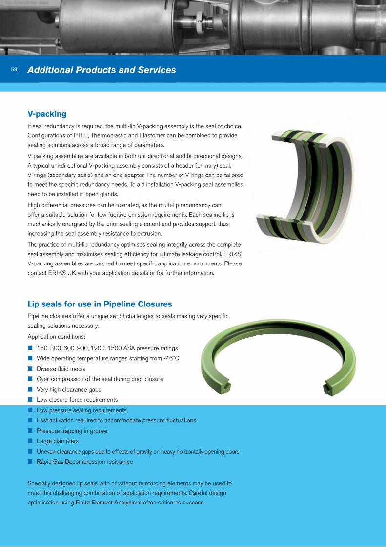
v-packingIf seal redundancy is required, the multi-lip V-packing assembly is the seal of choice.
Configurations of PTFE, Thermoplastic and Elastomer can be combined to provide
sealing solutions across a broad range of parameters.
V-packing assemblies are available in both uni-directional and bi-directional designs.
A typical uni-directional V-packing assembly consists of a header (primary) seal,
V-rings (secondary seals) and an end adaptor. The number of V-rings can be tailored
to meet the specific redundancy needs. To aid installation V-packing seal assemblies
need to be installed in open glands.
High differential pressures can be tolerated, as the multi-lip redundancy can
offer a suitable solution for low fugitive emission requirements. Each sealing lip is
mechanically energised by the prior sealing element and provides support, thus
increasing the seal assembly resistance to extrusion.
The practice of multi-lip redundancy optimises sealing integrity across the complete
seal assembly and maximises sealing efficiency for ultimate leakage control. ERIKS
V-packing assemblies are tailored to meet specific application environments. Please
contact ERIKS UK with your application details or for further information.
58 Additional Products and Services
Lip seals for use in pipeline ClosuresPipeline closures offer a unique set of challenges to seals making very specific
sealing solutions necessary:
Application conditions:
n 150, 300, 600, 900, 1200, 1500 ASA pressure ratings
n Wide operating temperature ranges starting from -46°C
n Diverse fluid media
n Over-compression of the seal during door closure
n Very high clearance gaps
n Low closure force requirements
n Low pressure sealing requirements
n Fast activation required to accommodate pressure fluctuations
n Pressure trapping in groove
n Large diameters
n Uneven clearance gaps due to effects of gravity on heavy horizontally opening doors
n Rapid Gas Decompression resistance
Specially designed lip seals with or without reinforcing elements may be used to
meet this challenging combination of application requirements. Careful design
optimisation using Finite Element Analysis is often critical to success.

59
ERIKS’ product knowledge ensures you
always get the right gasket for the job.
Our gasket installation kits for example,
have the seals and gaskets logically
packed for ease of assembly, to save
you time.
We design, manufacture and supply
a wide range of essential sealing
and insulation components to many
industries where equipment failure is not
an option. Products include cut gaskets,
packings, sheet jointing materials,
moulded seals and shaped thermal
insulation components, all vital to a
modern industrial society.
By closely working with leading material
manufacturers we offer a range of
quality products at cost-effective prices.
Cut gaskets and sheet jointing available
from every imaginable sealing material
including specialised materials
Gaskets
Rubber MouldingsThe moulding of rubber and elastomeric
compounds is accomplished by forcing
the material into a shape using heat and
pressure. Rubber and elastomers can
be moulded by compression, transfer
and injection methods. The volume of
parts and type of compound required
will determine the moulding method
used. Our engineers participate with
you to develop innovative solutions for
your production.
Extruded Rubber profiles/InflatablesOur comprehensive product range
incorporates not only rubber, but also
Thermo Plastic Elastomer (TPE). Our
TPE solutions are a prime example of
our innovative thinking, combining two
or three thermo plastic elastomers in
one product to reduce the steps in the
manufacturing process.
Our in-house CAD/CAM capability
also enables us to quickly design and
accurately manufacture innovative
solutions to meet new applications and
operating conditions utilising
our in-house 3D
rubber printing
capabilities.
Rubber Moulded and Extruded products
valvesIn addition we offer:
n Spiral Wound
Gaskets
n Gland Packings
n Ring Type Joints
n Extrusions
n Rubber Mouldings Rubber Proof
Woven Cloths
n Dry and Coated Woven Cloths
n Boiler House Products
n Thermal Insulation Fabrications
n Multi-ply Expansion Joints
and Strip
n Boiler Combustion
Chamber Insulation
n Boiler/Cooker Case Insulation
Econosto offer a wide range
of oil & gas valves from stock
held locally both at Aberdeen and
Leicester.
These may be supplied with API 6D
and API 6A approvals for wellhead and
Christmas tree equipment.
From stock:
Forged steel gate
Globe and check valves
Ball valves
Trunnion-mounted ball valves
upon request:
Tandem trunnion ball valves
Floating ball valves
Bypass valves with high temperature
and cryogenic options

ERIKS Sealing Technology ERIKS Sealing Technology offers a comprehensive range of high performance sealing
products, supported by a world-class technical and logistical service to deliver the right
seal on time to your critical applications.
ERIKS Sealing Technology unit 5, Yorks park Blowers Green RoadDudley West MidlandsDY2 8uL
Tel 0845 603 1221Fax 0845 603 1441 www.eriks.co.uk
ERIKS Sealing Technology206 Cavendish placeBirchwood parkWarringtonCheshireWa3 6Wu
Tel 01925 853000Fax 01925 853030