erin non boiler solid fuel stove - waterford stanleysecondary air damper assembly note: ensure that...
TRANSCRIPT

Erin Non Boiler Solid Fuel Stove
INSTALLATION AND OPERATING INSTRUCTIONS
This appliance is hot while in operation and retains its heat for a long period of time after use.
Children, aged or infirm persons should be supervised at all times and should not be allowed to touch
the hot working surfaces while in use or until the appliance has thoroughly cooled.
When using the stove in situations where children, aged and/or infirm persons are present a fireguard
must be used to prevent accidental contact with the stove. The fireguard should be manufactured in
accordance with BS 8423:2002.

TABLE OF CONTENTS
PAGE NO.
1. General . . . . . . . . . . . . . . . . . . . . . . . . . . . . . . . . . . . . . . . . . . . . . . . . . . . . . . . . . . . . . . . . . . . . . . .3Handling . . . . . . . . . . . . . . . . . . . . . . . . . . . . . . . . . . . . . . . . . . . . . . . . . . . . . . . . . . . . . . . . . . . .3
Fire Cement . . . . . . . . . . . . . . . . . . . . . . . . . . . . . . . . . . . . . . . . . . . . . . . . . . . . . . . . . . . . . . . . . .3
Asbestos . . . . . . . . . . . . . . . . . . . . . . . . . . . . . . . . . . . . . . . . . . . . . . . . . . . . . . . . . . . . . . . . . . . .3
Metal Parts . . . . . . . . . . . . . . . . . . . . . . . . . . . . . . . . . . . . . . . . . . . . . . . . . . . . . . . . . . . . . . . . . .3
2. Pre-Installation Assembly . . . . . . . . . . . . . . . . . . . . . . . . . . . . . . . . . . . . . . . . . . . . . . . . . . . . . . . . . .3
3. Top Flue Exit . . . . . . . . . . . . . . . . . . . . . . . . . . . . . . . . . . . . . . . . . . . . . . . . . . . . . . . . . . . . . . . . . . .4
4. Rear Flue Exit . . . . . . . . . . . . . . . . . . . . . . . . . . . . . . . . . . . . . . . . . . . . . . . . . . . . . . . . . . . . . . . . . .5
5. Flues . . . . . . . . . . . . . . . . . . . . . . . . . . . . . . . . . . . . . . . . . . . . . . . . . . . . . . . . . . . . . . . . . . . . . . . . .5
6. Flue Pipes . . . . . . . . . . . . . . . . . . . . . . . . . . . . . . . . . . . . . . . . . . . . . . . . . . . . . . . . . . . . . . . . . . . . .5
7. Chimney . . . . . . . . . . . . . . . . . . . . . . . . . . . . . . . . . . . . . . . . . . . . . . . . . . . . . . . . . . . . . . . . . . . . . . .6
8. Ventilation & Combustion Air Requirements . . . . . . . . . . . . . . . . . . . . . . . . . . . . . . . . . . . . . . . . . . .6
9. Permanent Air Vent . . . . . . . . . . . . . . . . . . . . . . . . . . . . . . . . . . . . . . . . . . . . . . . . . . . . . . . . . . . . . .6Extractor Fan . . . . . . . . . . . . . . . . . . . . . . . . . . . . . . . . . . . . . . . . . . . . . . . . . . . . . . . . . . . . . . . . .6
10. Location . . . . . . . . . . . . . . . . . . . . . . . . . . . . . . . . . . . . . . . . . . . . . . . . . . . . . . . . . . . . . . . . . . . . . . .6
11. Installation Clearances . . . . . . . . . . . . . . . . . . . . . . . . . . . . . . . . . . . . . . . . . . . . . . . . . . . . . . . . . . . .7
12. Floor Protection . . . . . . . . . . . . . . . . . . . . . . . . . . . . . . . . . . . . . . . . . . . . . . . . . . . . . . . . . . . . . . . . .7
13. Commissioning & Handover . . . . . . . . . . . . . . . . . . . . . . . . . . . . . . . . . . . . . . . . . . . . . . . . . . . . . . .7
14. Important Notes . . . . . . . . . . . . . . . . . . . . . . . . . . . . . . . . . . . . . . . . . . . . . . . . . . . . . . . . . . . . . . . . .8
15. Lighting the Stove . . . . . . . . . . . . . . . . . . . . . . . . . . . . . . . . . . . . . . . . . . . . . . . . . . . . . . . . . . . . . . .9
16. Specification . . . . . . . . . . . . . . . . . . . . . . . . . . . . . . . . . . . . . . . . . . . . . . . . . . . . . . . . . . . . . . . . . . . .10
17. Technical Data . . . . . . . . . . . . . . . . . . . . . . . . . . . . . . . . . . . . . . . . . . . . . . . . . . . . . . . . . . . . . . . . . .10
18. Operating Instructions . . . . . . . . . . . . . . . . . . . . . . . . . . . . . . . . . . . . . . . . . . . . . . . . . . . . . . . . . . . .11
19. Recommended Fuels . . . . . . . . . . . . . . . . . . . . . . . . . . . . . . . . . . . . . . . . . . . . . . . . . . . . . . . . . . . . .11
20. Primary Air Control . . . . . . . . . . . . . . . . . . . . . . . . . . . . . . . . . . . . . . . . . . . . . . . . . . . . . . . . . . . . . . .11
21. Air Wash Control . . . . . . . . . . . . . . . . . . . . . . . . . . . . . . . . . . . . . . . . . . . . . . . . . . . . . . . . . . . . . . . .11
22. Secondary Air Control . . . . . . . . . . . . . . . . . . . . . . . . . . . . . . . . . . . . . . . . . . . . . . . . . . . . . . . . . . . .12
23. Low/Slumber Burn . . . . . . . . . . . . . . . . . . . . . . . . . . . . . . . . . . . . . . . . . . . . . . . . . . . . . . . . . . . . . . .12
24. Burning of Anthracite or Somkeless Coal . . . . . . . . . . . . . . . . . . . . . . . . . . . . . . . . . . . . . . . . . . . . .12
25. De-Ashing . . . . . . . . . . . . . . . . . . . . . . . . . . . . . . . . . . . . . . . . . . . . . . . . . . . . . . . . . . . . . . . . . . . . .12
26. Disposal of Ashes . . . . . . . . . . . . . . . . . . . . . . . . . . . . . . . . . . . . . . . . . . . . . . . . . . . . . . . . . . . . . . .12
27. To Clean Chimney Outlet . . . . . . . . . . . . . . . . . . . . . . . . . . . . . . . . . . . . . . . . . . . . . . . . . . . . . . . . . .13
28. To Replace Damaged Grate or Rocker Bar . . . . . . . . . . . . . . . . . . . . . . . . . . . . . . . . . . . . . . . . . . . .13
29. To Replace Damaged Bricks . . . . . . . . . . . . . . . . . . . . . . . . . . . . . . . . . . . . . . . . . . . . . . . . . . . . . . .13
30. CO Alarm . . . . . . . . . . . . . . . . . . . . . . . . . . . . . . . . . . . . . . . . . . . . . . . . . . . . . . . . . . . . . . . . . . . . . .13
31. Fire Safety . . . . . . . . . . . . . . . . . . . . . . . . . . . . . . . . . . . . . . . . . . . . . . . . . . . . . . . . . . . . . . . . . . . . .13
32. In Case of Fire . . . . . . . . . . . . . . . . . . . . . . . . . . . . . . . . . . . . . . . . . . . . . . . . . . . . . . . . . . . . . . . . . .13
33. Vitreous Enamel Cleaning . . . . . . . . . . . . . . . . . . . . . . . . . . . . . . . . . . . . . . . . . . . . . . . . . . . . . . . . .13
34. Cleaning Glass . . . . . . . . . . . . . . . . . . . . . . . . . . . . . . . . . . . . . . . . . . . . . . . . . . . . . . . . . . . . . . . . . .14
35. Glass Replacement . . . . . . . . . . . . . . . . . . . . . . . . . . . . . . . . . . . . . . . . . . . . . . . . . . . . . . . . . . . . . .14
36. Door Latch Adjustment . . . . . . . . . . . . . . . . . . . . . . . . . . . . . . . . . . . . . . . . . . . . . . . . . . . . . . . . . . . .14
37. Periods of Prolonged Non-Use . . . . . . . . . . . . . . . . . . . . . . . . . . . . . . . . . . . . . . . . . . . . . . . . . . . . .14
38. Exploded View . . . . . . . . . . . . . . . . . . . . . . . . . . . . . . . . . . . . . . . . . . . . . . . . . . . . . . . . . . . . . . . . . .15
39. Installation Check List . . . . . . . . . . . . . . . . . . . . . . . . . . . . . . . . . . . . . . . . . . . . . . . . . . . . . . . . . . . .16
2
ERIN SOLID FUEL NON BOILER STOVE
INSTALLATION & OPERATING INSTRUCTIONS
GENERAL
When installing, operating and maintaining your
Erin Stove respect basic standards of fire safety.
Read these instructions carefully before commenc-
ing the installation. Failure to do so may result in
damage to persons and property. Consult your local
Municipal office and your insurance representative
to determine what regulations are in force. Save
these instructions for future reference.
Please note that it is a legal requirement under
England & Wales Building Regulations that the
installation of the stove is either carried out under
Local Authority Building Control approval or is
installed by a Competent Person registered with a
Government approved Competent Persons
Scheme. HETAS Ltd operate such a scheme and a
listing of their Registered Competent Persons can
be found on their website at www.hetas.co.uk.
Special care must be taken when installing the stove
such that the requirements of the Health & Safety at
Work Act are met.
Handling
Adequate facilities must be available for loading,
unloading and site handling.
Fire Cement
Some types of fire cement are caustic and should
not be allowed to come into contact with the skin. In
case of contact with the skin wash immediately with
plenty of water.
Asbestos
This stove contains no asbestos. If there is a possi-
bility of disturbing any asbestos in the course of
installation then please seek specialist guidance and
use appropriate protective equipment.
Metal Parts
When installing or servicing this stove care should
be taken to avoid the possibility of personal injury.
“IMPORTANT WARNING”
This stove must not be installed into a chimney that
serves any other heating appliance.
There must not be an extractor fan fitted in the same
room as the stove as this can cause the stove to
emit fumes into the room.
3
The complete installation must be done inaccordance with current Standards and LocalCodes. It should be noted that the require-ments and these publications may be super-seded during the life of this manual.
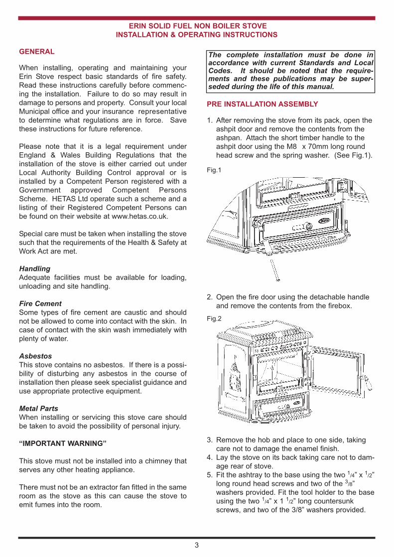
Fig.1
Fig.2
3. Remove the hob and place to one side, taking
care not to damage the enamel finish.
4. Lay the stove on its back taking care not to dam-
age rear of stove.
5. Fit the ashtray to the base using the two 1/4” x 1/2”
long round head screws and two of the 3/8”
washers provided. Fit the tool holder to the base
using the two 1/4” x 1 1/2” long countersunk
screws, and two of the 3/8” washers provided.
2. Open the fire door using the detachable handle
and remove the contents from the firebox.
PRE INSTALLATION ASSEMBLY
1. After removing the stove from its pack, open the
ashpit door and remove the contents from the
ashpan. Attach the short timber handle to the
ashpit door using the M8 x 70mm long round
head screw and the spring washer. (See Fig.1).

Fig.3
Fig.4
6. Fit the secondary air control rod bracket to the
ashtray using the two 1/4” x 1/2” long round head
screws and the two lock washers provided. Fit
the connecting rod through the control rod brack-
et with the notches facing downwards and leave
it hanging loose until the stove is standing
upright. See Fig.4.
7. Remove the four M10 bolts from the base,
and fit the four legs using the four M10 x 20mm
long bolts and the 3/8” washers provided in the
jiffy bag. (See Fig.5).
Fig.5
9. Stand the stove upright, taking care not to strain
the back leg bolts. Attach the secondary air
damper assembly to the back panel using the two1/4” x 3/4” long round head screws and the two
lock washers provided (See Fig.6). Connect the
connecting rod to the secondary air damper
assembly and fix it into place using the split pin
and 1/4” washer provided in the jiffy bag. Ensure
that the ends of the split pin are bent back with
the 1/4” washer between the casting and the
ends of the split pin. See Fig 7.
Fig.6
Secondary Air
Damper Assembly
Note: Ensure that the secondary air damper is
sealing against the back panel when the connecting
rod is in the closed position. (see section on
Secondary Air Control).
TOP FLUE EXIT
Fit the top flue spigot to the top of the stove as
shown in Fig.8, and cement into place. Ensure that
no cement blocks the flue passageway.
Fig.7
4

Fig.8
REAR FLUE EXIT
Remove the back flue cover plate from the back of
the stove and using the 1/4” countersunk screws for
the cover plate, attach the top flue outlet hob cover
plate (see Fig.8).
FLUES
It is not possible to sweep the chimney through this
appliance. Allow adequate access to the flue and
chimney for sweeping. Flues should be vertical
wherever possible and where a bend is necessary, it
should not make an angle of more than 45o with the
vertical. Horizontal flue runs should be avoided
except in the case of a back outlet appliance, when
the length of the horizontal section should not
exceed 150mm.
In order to minimise flue resistance and to make
sweeping easier it is recommended to use 2 x 45o
bends rather than a 90o bend.
The flue termination point must be located to min-
imise any wind effects. Wind effects of suction,
pressure zones and turbulence can be created by
the roof and adjacent objects. Wind effects can also
be created by natural land contours.
To minimise the wind effects, the flue termination
point should be located a minimum of 1000mm from
the roof measured vertically and 2300mm measured
horizontally. Where this termination point does not
suffice it may be necessary to extend the flue pipe
so that the termination point is above the apex. (See
Fig.9)-
Fig.9
FLUE PIPES
A flue pipe should only be used to connect an appli-
ance to a chimney and should not pass through any
roof space.
Flue pipes may be of any of the following materials:
(a) Cast iron as described in BS 41:1973
(1981), or
(b) Mild steel with a wall thickness of at
least 3mm, or
(c) Stainless steel with a wall thickness of
at least 1mm and as described in BS
EN 10095:1999 Specification for stain
less and heat resisting steel plate,
sheet and strip, for Grade 316 S11,
316 S13, 316 S16, 316 S31, 316 S33,
or the equivalent Euronorm 88-71
designation, or(d) Vitreous enamelled steel complying
with BS 6999: 1989.
Flue pipes with spigot and socket joints should be fit-
ted with the socket uppermost.
Clearance to combustibles must be adhered to
when fitting the flue pipe.
The flue gas mass flow is 8.2 g/s solid mineral fuel
and 7.7g/s wood logs. The mean flue gas tempera-
ture measured directly downstream of the spigot at
nominal heat output is 344oC. The appliance is suit-
able for continuous operation on solid mineral fuel
and intermittent operation on wood logs.
5

6
CHIMNEY
The Erin is a radiant room heater and must be con-
nected to a chimney of the proper size and type.
The chimney must have a cross-sectional area of at
least 30 square inches 18150sq. mm or a diameter
of at least 6” (150mm). It is best to connect to a
chimney of the same size, as connection to
a larger size may result in a somewhat less draught.
Do not connect to a chimney serving another appli-
ance. Minimum chimney height 15’ (4.5 meters)
from floor on which stove is installed. An existing
masonry chimney should be inspected and if neces-
sary repaired by a competent mason. The stove
must be connected to a chimney with a minimum
continuous draft of .06” wg (15 Pascals). Poor draft
conditions will result in poor performance.
Chimneys for use with solid fuel appliances should
be capable of withstanding a temperature of 1100oC
without any structural change which would impair
the stability or performance of the chimney.
If the stove is fitted in place of an open fire then the
chimney should be swept again, one month after
installation, to clear any soot falls which may have
occurred due to the difference in combustion
between the stove and the open fire.
BS EN 15287-1:2007, Design Installation and
Commissioning of Chimneys; Part 1: Chimneys for
non-roomsealed heating appliances should be used.
VENTILATION & COMBUSTION AIR REQUIRE-MENTS
It is imperative that there is sufficient air supply tothe stove in order to support correct combustion.The air supply to this appliance must comply withB.S. 8303: Part 1. The minimum effective air require-ment for this appliance in Ireland is 65cm2. In theUK the air requirement is 60.1cm2 if a flue draughtstabiliser is used or 29.2cm2 without.
If there is another air using appliance fitted in thesame or adjacent room, it will be necessary to cal-culate additional air supply.
All materials used in the manufacture of air ventsshould be such that the vent is dimensionally stableand corrosion resistant.
The effective free area of any vent should be ascer-tained before installation. The effect of any screenshould be allowed for when determining the effectivefree area of any vent.
Air vents direct to the outside of the building shouldbe located so that any air current produced will notpass through normally occupied areas of the room.
An air vent outside the building should not be locat-ed less than the dimensions specified within theBuilding Regulations from any part of any flue termi-nal. These air vents must also be fire proofed as perBuilding Regulations.
Air vents traversing cavity walls should include acontinuous duct across the cavity. The duct shouldbe installed in such a manner as not to impair theweather resistance of the cavity.
Joints between air vents and outside walls should besealed to prevent the ingress of moisture. Existingair vents should be of the correct size and unob-structed for the appliance in use.
If there is an air extraction fan or other air usingappliance fitted in the room or adjacent rooms wherethis appliance is fitted, additional air vents will berequired to eleviate the possibility of spillage of prod-ucts of combustion from the appliance/flue while thefan is in operation.
Where such a installation exists, a test for spillageshould be made with the fan or fans and other appli-ances using air in operation at full rate, (i.e. extrac-tion fans, tumble dryers) with all external doors andwindows closed.
If spillage occurs following the above operation, anadditional air vent of sufficient size to prevent thisoccurrence should be installed.
PERMANENT AIR VENT
The stove requires a permanent and adequate air
supply in order for it to operate safely and efficiently.
In accordance with current Building Regulations the
installer will have fitted a permanent air supply vent
into the room in which the stove is installed to pro-
vide combustion air. This air vent should not under
any circumstances be shut off or sealed.
Extractor Fan
There must not be an extractor fan fitted in the same
room as the stove as this can cause the stove to
emit smoke and fumes into the room.
LOCATION
There are several conditions to be considered in
selecting a location for your Erin Stove.
a. Position in the area to be heated- central
locations are usually best.
b. Allowances for proper clearances to
combustibles.
NOTE: Sufficient space should be given around the
back and sides of the stove to allow access to the
secondary air control damper.

INSTALLATION CLEARANCES
Maintain at least the following clearances to all
combustible material:
From the front 910 mm
From the back 900 mm
From the sides 700 mm
From the flue pipe 910 mm
straight up only
It is recommended that this appliance is sited next to
and on a non-combustible surface. A minimum all
round clearance of 100 mm will allow air circulation
and not impede the performance of the stove.
FLOOR PROTECTION
It is recommended that this appliance is installed on
a solid, level, non- combustible hearth conforming to
current Building Regulations. See Fig. 10.
7
127mm 127mm
225mm
127mmFig.10
COMMISSIONING & HANDOVER
On completion of the installation allow a suitable
period of time for any fire cement and mortar to dry
out, when a small fire may be lit and checked to
ensure the smoke and fumes are taken from the
stove up the chimney and emitted safely to the
atmosphere. Do not run at full output for at least 24
hours.
On Completion of the installation ensure that the
operating instructions for the stove are left with the
customer. Ensure to advise the customer on the
correct use of the appliance with the fuels likely to be
used on the stove and warn them to use only the
recommended fuels for the stove.
Advise the user what to do should smoke or fumes
be emitted from the stove. The customer should be
warned to use a fireguard to BS 6539 in the pres-
ence of children, aged and/or infirm persons.

IMPORTANT NOTES
Now that your Stanley solid fuel Stove is installed and no doubt you are looking forward to many comforts it will
provide, we would like to give you some tips on how to get the best results from your stove.
1. We would like if you could take some time to read the operating instructions/hints, which we are
confident, will be of great benefit to you.
2. Do not burn fuel with a high moisture content, such as a damp peat or unseasoned timber. This
will only result in a build up of tar in the stove and in the chimney.
3. CLEAN THE FLUE-WAYS OF THE STOVE EVERY WEEk AND ENSURE THAT THERE ARE
NO BLOCkAGES. PLEASE REFER TO MANUAL FOR INSTRUCTIONS.
4. Before loading fresh fuel into the firebox, riddle fully to remove all ashes this will allow better and
cleaner burning. See directions in manual.
5. Never allow a build up of ashes in the ash pan, as this will cause the grate to burn out prema-
turely.
6. Avoid slow burning of damp or unseasoned fuel as this will result in tarring flue ways and chim-
ney i.e. peat or timber.
7. Allow adequate air ventilation to ensure plenty of air for combustion.
8. Do not burn rubbish/household plastic.
9. The ash door can only be opened when the fire door is opened first. This is to prevent the ash
door being left open when the fire door is closed, causing damage to the stove.
10. Clean the chimney at least twice a year.
11. Burning soft fuels such as timber and peat will stain the glass. Regular cleaning will prevent per-
manent staining.
12. Keep all combustible materials a safe distance away from unit, please see section for clear-
ances to combustibles.
13. For safety reasons never leave children unaccompanied while stove is in use.
14. Avoid contact with unit when in use as stove reaches very high operating temperatures.
15. Do not use an aerosol spray on or near the stove when it is alight.
FUEL CALORIFIC VALUES - SOLID FUELS
Anthracite 25-50mm C.V.: 8.2kW/Kg 14,000 BTUs/lb
House Coal 25-75mm C.V.: 7.2kW/Kg 12,000 BTUs/lb
Timber - Firebox size C.V.: 5.0kW/Kg 8,600 BTUs/lb
Peat Briquettes C.V.: 4.8kW/Kg 8,300 BTUs/lb
Bog Peat C.V.: 3.4kW/Kg 6,000 BTUs/lb
8

LIGHTING
1. Before lighting the stove, ensure that any build up in the firebox has been removed (see
De-Ashing Section) and that the ashpan has been emptied.
2. Open firedoor and open the primary air inlet by sliding the control knob on the ashpit
door to the right hand side.
3. Open the secondary air inlet by turning it anti-clockwise.
4. Cover with crumpled pieces of paper.
5. Lay 10-12 pieces of kindling on top of the paper towards the back of the firebox.
6. Ignite and close the firedoor.
7. Under no circumstances should any flammable liquid i.e. petrol, paraffin etc.,
be used to light the fire.
8. When the kindling is well alight open the firedoor and add more kindling of a larger size
to sustain the fire. Close the firedoor.
9. When a hot bed of coals is established add the normal fuel.
10. When well lighted, adjust the air controls to give the required heat output.
11. Always open the firedoor first before opening the ash door. Do not only open the ash
door to de-ash the appliance as this will cause the fire to run away and may cause dam-
age if left open for a prolonged period , with the firedoor closed.
Re-fuelling - Open the firedoor and reload, close the firedoor.
9
Before lighting the stove check with the installer that the installation work and
commissioning checks described in the installation instructions have been carried out
correctly and that the chimney has been swept clean, is sound and free from any
obstructions. As part of the stove’s commissioning and handover the installer should
have demonstrated how to operate correctly.
Fig.11

10
Fig.12
SPECIFICATION
Note: Dimensions stated are in millimetres and may be subject to a slight +/- variation.
Typical refuelling intervals to obtain nominal out-
puts
Wood 1.5 hours 5.5kgs
MSF 4 hours 6.5kgs
Flue Gas Mass Flow Wood 7.7 g/s
MSF 8.2 g/s
Flue Gas temp at nominal output 344oC
Gross Weight: 172 kgs
Flue Outlet 153 mm Log size 406 mm
This appliance has been tested in
accordance with BS EN 13240
Flue draught 15 Pascals
OUTPUT TO ROOM TOTAL OUTPUT
NOMINAL MAX. NOMINAL MAX.
WOOD LOGS 10.2 kW 10.2kW
MANUFACTURED
SMOkELESS FUEL
10.4 kW 14.7kW 10.4kW 14.7kW
TECHNICAL DATA

OPERATING INSTRUCTIONS
RECOMMENDED FUELS
All fuels should be stored under cover and kept
as dry as possible prior to use.
This appliance has been tested using seasoned
wood logs and manufactured briquetted smokeless
fuel (Ancit) for closed appliances, sized between
20g and 140g. Other fuels are commercially avail-
able and may give similar results. Wood logs up to
406mm long are suitable. All fuels should be stored
under cover and kept as dry as possible prior to use.
Do not use fuels with a Petro-coke ingredient as this
may cause the grate to overheat, causing damage.
Reduced outputs will result when fuels of lower
calorific values are used. Never use gasoline or
gasoline type lantern fuel, kerosene, charcoal lighter
fluid or similar liquids to start or freshen up a fire in
this heater. Keep all such liquid well away from the
heater at all times. Operate the stove only with the
fuelling door closed except for re-fuelling.
This stove has obtained HETAS Ltd approval for
burning natural and manufactured smokeless fuels
and wood logs only as detailed in recommended
fuels below. HETAS Approval does not cover the
use of other fuels either alone or mixed with the rec-
ommended fuels listed, nor does it cover instructions
for the use of other fuels.
WARNING: DO NOT OBSTRUCT SECONDARY
AIR SUPPLY TO THE AIR DUCT AT THE BACk
OF THE STOVE
WARNING:
Properly installed, operated and maintained this
stove will not emit fumes into the dwelling.
Occasional fumes from de-ashing and re-fuelling
may occur. However, persistent fume emission is
potentially dangerous and must not be tolerated. If
fume emission does persist, then the following
immediate action should be taken -
(a) Open doors and windows to ventilate room.
(b) Let the fire out or eject and safely dispose of
fuel from the stove.
(c) Check for flue or chimney blockage and clean if
required.
(d) Do not attempt to relight the fire until the cause
of the fume emission has been identified and
corrected. If necessary seek expert advice.
The most common cause of fume emission is flue-
way or chimney blockage. For your own safety
these must be kept clean at all times.
PRIMARY AIR CONTROL
The primary air for the stove is controlled by sliding
the primary air control knob on the ashpit door. The
control knob should be moved right for the maximum
burn setting and moved to the left for the minimum
burn setting. Fig.14 shows the various positions for
the control knob corresponding to their burn rates.
When operating the stove for the first time put the air
controls in a mid position first to become familiar
with the heat output obtained from different fuels.
Primary Air Control
Other Settings
Fully Closed
Fig.14
AIR WASH CONTROL
The amount of air supplied to the air wash is con-
trolled by adjusting the air wash control knob on the
top of the front casting. The air wash is adjusted by
inserting the moulded end of the operating tool onto
the air wash control knob and twisting it clockwise to
close it and anti-clockwise to open it. (see Fig.15)
When burning wood this control being open will help
to keep the glass clean. For nominal heat output
slide the primary air control to the closed to half
open position and use the air wash control to adjust
the burning rate. The best positions will be learned
over a period of time.
Fig.13
Air Wash Control Knob
Primary Air Control Knob
Secondary Air Pull Lever
Located Under Ash-Shelf
Full Open
11

Fig.15
Air Wash Control
OPEN When burning coal, timber or peat.
CLOSE When burning anthracite, and smokeless fuels.
SECONDARY AIR CONTROL
The secondary air is adjusted by adjusting the posi-
tion of the secondary air connecting rod, which is
located underneath the ash tray. Pulling the rod out
to the last notch on the connecting rod, gives the
maximum amount of secondary air and pushing it
back towards the stove, closes the secondary air
completely.
When burning wood this control only needs to be
cracked open and closed when burning smokeless
fuels.
Fig.17
Fig.16
Air Wash Control
BURNING OF ANTHRACITE OR SMOkELESS
COAL
When burning anthracite or smokeless coal, close
the air wash control knob by turning it in a clockwise
direction. Open the primary air control knob by slid-
ing it fully towards the right. Close the secondary air
control by lifting the secondary air connecting rod
and pushing it fully back until the notch engages in
the connecting rod bracket.
NOTE: When burning anthracite or smokeless coal,
the air wash and secondary air damper must be
closed.
LOW / SLUMBER BURN
To achieve an overnight or a low burn rate, close the
air wash control knob and the secondary air control.
Slide the primary air control knob until it is approxi-
mately 3mm open. If the fuel load is too small or the
draught too strong, the primary air control knob may
need to be closed even further to sustain the low
burn rate.
DE-ASHING
When ash build-up becomes excessive in the fire
chamber shake the firebars by inserting the grate
operating tool into the rocker connection at the right
hand side of the stove, and turning it clockwise and
anticlockwise to achieve the rocker motion.
Fig.18
DISPOSAL OF ASHES
When opening the ash door the fire door must be
opened first.
The stove is provided with a steel ashpan. This ash-
pan must be emptied every day.
If ashes are allowed to build up to grate level the fire-
bars could be damaged by overheating. We recom-
mend that you remove ashes after you have riddled
the fire following an overnight burn.
Note: The stove should never be operated with the
ashpit door open.
Ashes should be placed in a metal or other non-
combustible container with a tight fitting lid. The
closed container of ashes should be placed on a
non-combustible material, pending final disposal. If
ashes are buried in soil, or otherwise dumped they
should be retained in the closed container until they
are thoroughly cooled.
12

13
Fig.19
Replace Ashpan. Close Ashpit Door & Fire Door
TO CLEAN CHIMNEY OUTLET
Remove the hob and place to one side, taking care
not to damage the enamel finish. Remove the heat
exchanger by unscrewing the four 1/4” round head
screws, and insert the cleaning brush. Replace the
heat exchanger, ensuring that the rope has not
moved out of position or been damaged. Replace
the hob before relighting the fire.
TO REPLACE DAMAGED GRATE OR ROCkER
BAR
Clean the firebox thoroughly and remove the fire
fence. Lift up the back rocker bar by catching it in
the centre until it disengages from the front rocker
bar and take it out of the fire box. Lift up the front
rocker bar by catching it at the end on the left hand
side of the firebox until it disengages from the rock-
er sleeve and take out of the firebox. Replace the
damaged part and replace the rocker bars by doing
the reverse of the above. Fig 20 shows all the fire-
box parts removed.
TO REPLACE DAMAGED BRICkS
Clean the firebox thoroughly and remove any fire
cement in the joints of the bricks. Remove the left
and right hand front bricks. Remove the two back
bricks. To remove the side bricks (left or right), lift
the top side brick up and hold it in position. Lift up
the bottom side brick to clear the rocker bar frame
then swing the bottom brick and take it out. Lower
the top firebrick and take it out at the firebox.
Replace the damaged brick and replace the bricks
by doing the reverse of the above.
CO ALARM
Waterford Stanley recommend the fitting of a CO
Alarm in the same room as the appliance, this is a
requirement under UK Building Regulations.
Further guidance on the installation of a carbon
monoxide alarm is available in BS EN 50292:2002
and from the alarm manufacturers instructions.
Fig.20
FIRE SAFETY
To provide reasonable fire safety, the following
should be given serious consideration.
1. Do not over fire the stove.
2. Over-firing will also damage painted or enamel
finish.
3. Install a smoke detector in the room.
4. A conveniently located class A fire extinguisher
to contend with small fires resulting from burn-
ing embers.
5. A practical evacuation plan.
6. A plan to deal with a chimney fire as follows:-
(a) Notify the fire department.
(b) Prepare occupants for immediate evacua-
tion.
(c) Close all openings into the stove.
(d) While awaiting the fire department watch for
ignition to adjacent combustibles from over
heated flue pipe or from embers or sparks
from the chimney.
IN CASE OF FIRE
Close all openings into the stove and watch for igni-
tion of adjacent combustibles from the over heated
stove, or hot embers or sparks from chimney.
Provision of an alarm must not be considered a
substitute for either installing the appliance
correctly or ensuring regular servicing and
maintenance of the appliance and chimney
system.
WARNING:-
If the CO Alarm sounds unexpectedly:-
1. Open Doors and windows to ventilate the
room and then leave the premises.
2. Let the fire go out.Ashpan

VITREOUS ENAMEL CLEANING
General cleaning must be carried out when the
stove is thoroughly cool.
If this stove is finished in a high gloss vitreous
enamel, to keep the enamel in the best condition
observe the following tips:
1. Wipe over daily with a soapy damp cloth,
followed by a polish with a clean dry duster.
2. For stubborn deposits a soap impregnated
pad can be carefully used on the vitreous
enamel.
3. Use only products recommended by the
Vitreous Enamel Association, these products
carry the Vitramel label.
4. DO NOT USE ABRASIVE PADS OR OVEN
CLEANSERS CONTAINING CITRIC ACID
ON ENAMELLED SURFACES. ENSURE
THAT THE CLEANSER MANUFACTUR-
ERS INSTRUCTIONS ARE ADHERED TO.
GLASS CLEANING
The glass will self clean when there is sufficient heat
generated by the burning fuel. If a build-up of cre-
osote occurs on the glass it may be due to draft con-
ditions, poor quality fuel or very low burning for a
long time. It is best to clean the glass when it is
thoroughly cooled.
GLASS REPLACEMENT
(a) Open the firedoor fully.
(b) Remove the four corner screws and clips and
carefully remove the broken glass.
(c) Clean the glass recess in the door.
(d) Attach adhesive thermal tape to the
14
Fig.21
DOOR LATCH ADJUSTMENT
If the door latch should be come loose over time due
to compression/ hardening of the rope inside the fire
door, an adjustment can be carried out by removing
one of the washers.
Remove the nut, spacer, latch and one washer, then
replace the nut, spacer and latch leaving only one
washer, see Figs. 22 & 23.
PERIODS OF PROLONGED NON-USE
If the stove is to be left unused for a prolonged peri-
od of time then it should be given a thorough clean
to remove ash and unburned fuel residues. To
enable a good flow of air through the appliance to
reduce condensation and subsequent damage,
leave the air controls fully open.
Fig.22
Fig.23
perimeter of the replacement glass.
(e) Place the thermal tape side of the glass into
the door recess and replace the four corner
clips.
(f) Tighten screws.
(g) Replace glass only with ceramic glass 5mm
thick.
15
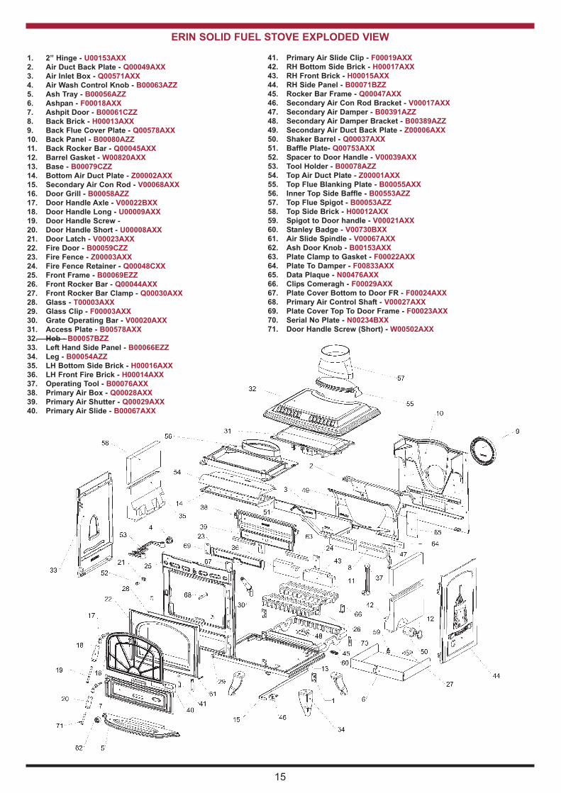
ERIN SOLID FUEL STOVE EXPLODED VIEW
1. 2” Hinge - U00153AXX
2. Air Duct Back Plate - Q00049AXX
3. Air Inlet Box - Q00571AXX
4. Air Wash Control knob - B00063AZZ
5. Ash Tray - B00056AZZ
6. Ashpan - F00018AXX
7. Ashpit Door - B00061CZZ
8. Back Brick - H00013AXX
9. Back Flue Cover Plate - Q00578AXX
10. Back Panel - B00080AZZ
11. Back Rocker Bar - Q00045AXX
12. Barrel Gasket - W00820AXX
13. Base - B00079CZZ
14. Bottom Air Duct Plate - Z00002AXX
15. Secondary Air Con Rod - V00068AXX
16. Door Grill - B00058AZZ
17. Door Handle Axle - V00022BXX
18. Door Handle Long - U00009AXX
19. Door Handle Screw -
20. Door Handle Short - U00008AXX
21. Door Latch - V00023AXX
22. Fire Door - B00059CZZ
23. Fire Fence - Z00003AXX
24. Fire Fence Retainer - Q00048CXX
25. Front Frame - B00069EZZ
26. Front Rocker Bar - Q00044AXX
27. Front Rocker Bar Clamp - Q00030AXX
28. Glass - T00003AXX
29. Glass Clip - F00003AXX
30. Grate Operating Bar - V00020AXX
31. Access Plate - B00578AXX
32. Hob - B00057BZZ
33. Left Hand Side Panel - B00066EZZ
34. Leg - B00054AZZ
35. LH Bottom Side Brick - H00016AXX
36. LH Front Fire Brick - H00014AXX
37. Operating Tool - B00076AXX
38. Primary Air Box - Q00028AXX
39. Primary Air Shutter - Q00029AXX
40. Primary Air Slide - B00067AXX
41. Primary Air Slide Clip - F00019AXX
42. RH Bottom Side Brick - H00017AXX
43. RH Front Brick - H00015AXX
44. RH Side Panel - B00071BZZ
45. Rocker Bar Frame - Q00047AXX
46. Secondary Air Con Rod Bracket - V00017AXX
47. Secondary Air Damper - B00391AZZ
48. Secondary Air Damper Bracket - B00389AZZ
49. Secondary Air Duct Back Plate - Z00006AXX
50. Shaker Barrel - Q00037AXX
51. Baffle Plate- Q00753AXX
52. Spacer to Door Handle - V00039AXX
53. Tool Holder - B00078AZZ
54. Top Air Duct Plate - Z00001AXX
55. Top Flue Blanking Plate - B00055AXX
56. Inner Top Side Baffle - B00553AZZ
57. Top Flue Spigot - B00053AZZ
58. Top Side Brick - H00012AXX
59. Spigot to Door handle - V00021AXX
60. Stanley Badge - V00730BXX
61. Air Slide Spindle - V00067AXX
62. Ash Door knob - B00153AXX
63. Plate Clamp to Gasket - F00022AXX
64. Plate To Damper - F00833AXX
65. Data Plaque - N00476AXX
66. Clips Comeragh - F00029AXX
67. Plate Cover Bottom to Door FR - F00024AXX
68. Primary Air Control Shaft - V00027AXX
69. Plate Cover Top To Door Frame - F00023AXX
70. Serial No Plate - N00234BXX
71. Door Handle Screw (Short) - W00502AXX

DP 130903 Rev 015Item No: N00229AXX
INSTALLATION CHECk LIST
Flue System
1. Minimum Flue Height of 4.5 metres (15 feet).
2. When an appliance is installed into an existing chimney, it should be connected to
a minimum of 1.8 meters (6 feet) of 150mm (6”) flue pipe with a horizontal run not
exceeding 150mm.
3. Appliance should be connected to a chimney of less than 200mm (8”) in diameter
(otherwise the chimney must be lined with a 6” flue liner).
4. The chimney venting position must comply with current Building Regulations.
5. The chimney serving this appliance should not serve any other appliance.
6. Access should be provided to the chimney serving the appliance to allow for cleaning.
Location
7. Clearance to combustible materials must be adhered to as described in the Clearance
to Combustible section.
8. The stove must be installed on a non combustible hearth.
Ventilation & Combustion Air Requirements
9. The room in which the appliance is located must have an air vent of adequate
size to support correct combustion (see Ventilation & Combustion Air Requirement
Section for specific details).
Tick
16
Manufactured by
Waterford Stanley Ltd.,
Unit 401-403, IDA Industrial Estate, Cork Road,
Waterford, Ireland.
Tel: (051) 302300 Fax (051) 302315
www.waterfordstanley.com