erl rf systems
DESCRIPTION
ERL RF Systems. A. Nassiri November 15, 2006. Presented to the Machine Advisory Committee for the Technical Review of APS Accelerator Upgrade Options – November 15-16, 2006. Outline. Goals Cavity design criterion Cavity parameters Frequency Cell Shape Number of cells Q vs. Gradient - PowerPoint PPT PresentationTRANSCRIPT
ERL RF Systems
A. Nassiri
November 15, 2006
Presented to the Machine Advisory Committee for the Technical Review of APS Accelerator Upgrade Options – November 15-16, 2006
2ERL RF Systems ( Exploring Options)A. Nassiri November 15, 2006
Outline
Goals Cavity design criterion
o Cavity parameters
o Frequency
o Cell Shape
o Number of cells
o Q vs. Gradient
o Cavity and wall-plug Power
o Fundamental RF Coupler
o HOM Coupler Cooling Requirement RF power sources and rf distribution LLRF system A summary of cavity design parameters Cavity R&D Conclusion
3ERL RF Systems ( Exploring Options)A. Nassiri November 15, 2006
Goals
To accelerate beam with up to 100 mA and 2-4 ps bunch length to 7 GeV CW operation Achieve and maintain rf amplitude and phase required for stability Preserve nm-type beam emittance in the linac Acceptable machine reliability and beam availability
4ERL RF Systems ( Exploring Options)A. Nassiri November 15, 2006
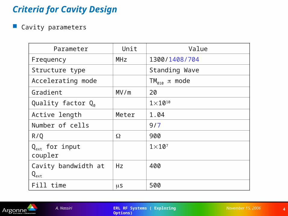
Criteria for Cavity Design
Cavity parameters
Parameter Unit Value
Frequency MHz 1300/1408/704
Structure type Standing Wave
Accelerating mode TM010 mode
Gradient MV/m 20
Quality factor Q0 11010
Active length Meter 1.04
Number of cells 9/7
R/Q 900
Qext for input coupler 1107
Cavity bandwidth at Qext Hz 400
Fill time s 500
5ERL RF Systems ( Exploring Options)A. Nassiri November 15, 2006
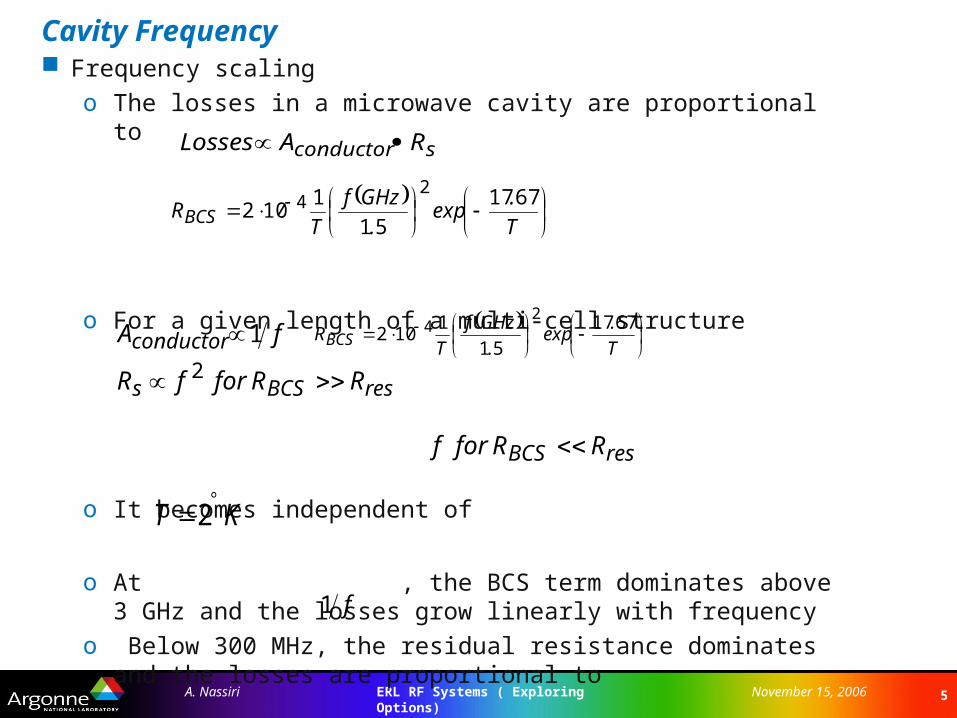
Cavity Frequency Frequency scaling
o The losses in a microwave cavity are proportional to
o For a given length of a multi-cell structure
o It becomes independent of
o At , the BCS term dominates above 3 GHz and the losses grow linearly with frequency
o Below 300 MHz, the residual resistance dominates and the losses are proportional to
sconductor RALosses
resBCSs
conductor
RRforfR
fA
1
2
resBCS RRforf
KT 2
f1
T
.exp
.
GHzf
TRBCS
6717
51
1102
24
T
.exp
.
GHzf
TRBCS
6717
51
1102
24
6ERL RF Systems ( Exploring Options)A. Nassiri November 15, 2006
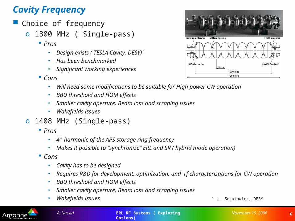
Cavity Frequency Choice of frequency
o 1300 MHz ( Single-pass) Pros
• Design exists ( TESLA Cavity, DESY)1
• Has been benchmarked
• Significant working experiences
Cons• Will need some modifications to be suitable for High power CW operation
• BBU threshold and HOM effects
• Smaller cavity aperture. Beam loss and scraping issues
• Wakefields issues
o 1408 MHz (Single-pass) Pros
• 4th harmonic of the APS storage ring frequency
• Makes it possible to “synchronize” ERL and SR ( hybrid mode operation)
Cons• Cavity has to be designed
• Requires R&D for development, optimization, and rf characterizations for CW operation
• BBU threshold and HOM effects
• Smaller cavity aperture. Beam loss and scraping issues• Wakefields issues 1 J. Sekutowicz, DESY
7ERL RF Systems ( Exploring Options)A. Nassiri November 15, 2006
Cavity Frequency Choice of frequency (Two-pass)
o 704 MHz Pros
• 2nd harmonic of the APS storage ring frequency
• Makes it possible to “synchronize” ERL and SR ( hybrid mode operation)
• Higher BBU threshold limit
• Injector design is simplified. Input power couplers will have higher power handling capability
• High peak current effects are reduced
• In principle can accelerate higher than 100 mA
Cons• Requires higher bunch charge ( ~150 pc for 100 mA average current), compared to
~77 pc at 1300 MHz
• This potentially affects emittance and source brightness
• Cavity fabrication and processing due to larger surface area
• Lower field gradient
8ERL RF Systems ( Exploring Options)A. Nassiri November 15, 2006
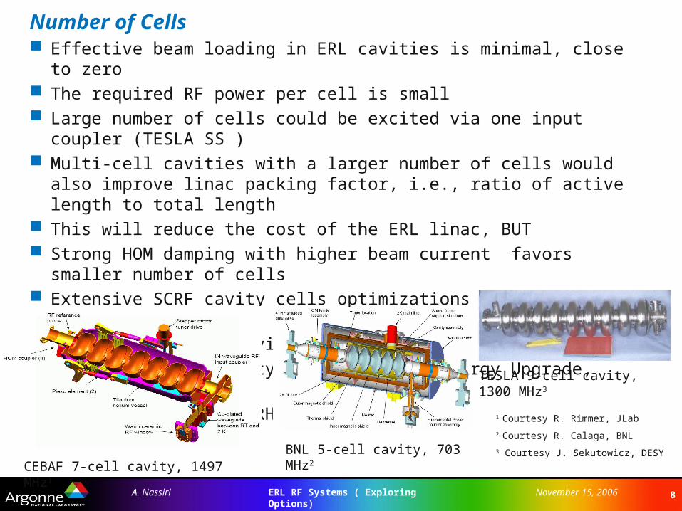
Number of Cells Effective beam loading in ERL cavities is minimal, close to zero The required RF power per cell is small Large number of cells could be excited via one input coupler (TESLA SS ) Multi-cell cavities with a larger number of cells would also improve linac packing
factor, i.e., ratio of active length to total length This will reduce the cost of the ERL linac, BUT Strong HOM damping with higher beam current favors smaller number of cells Extensive SCRF cavity cells optimizations have been done at TESLA and JLab
o TESLA – 9-cell cavity
o JLab- 7-cell cavity ( CEBAF 12 GeV Energy Upgrade, Renascence)
o BNL 703 MHz for eRHIC
TESLA 9-cell cavity, 1300 MHz3
CEBAF 7-cell cavity, 1497 MHz1
BNL 5-cell cavity, 703 MHz2
1 Courtesy R. Rimmer, JLab
2 Courtesy R. Calaga, BNL
3 Courtesy J. Sekutowicz, DESY
9ERL RF Systems ( Exploring Options)A. Nassiri November 15, 2006
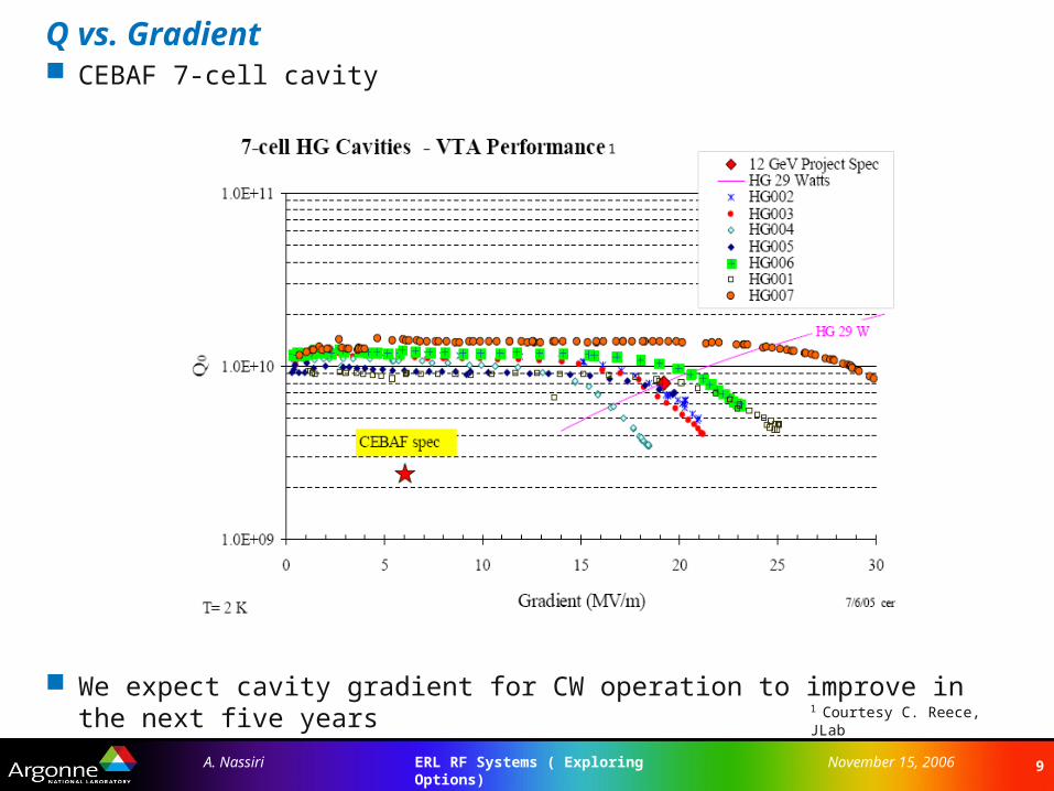
Q vs. Gradient CEBAF 7-cell cavity
We expect cavity gradient for CW operation to improve in the next five years1 Courtesy C. Reece, JLab
1
10ERL RF Systems ( Exploring Options)A. Nassiri November 15, 2006
Cavity and Wall-Plug Power
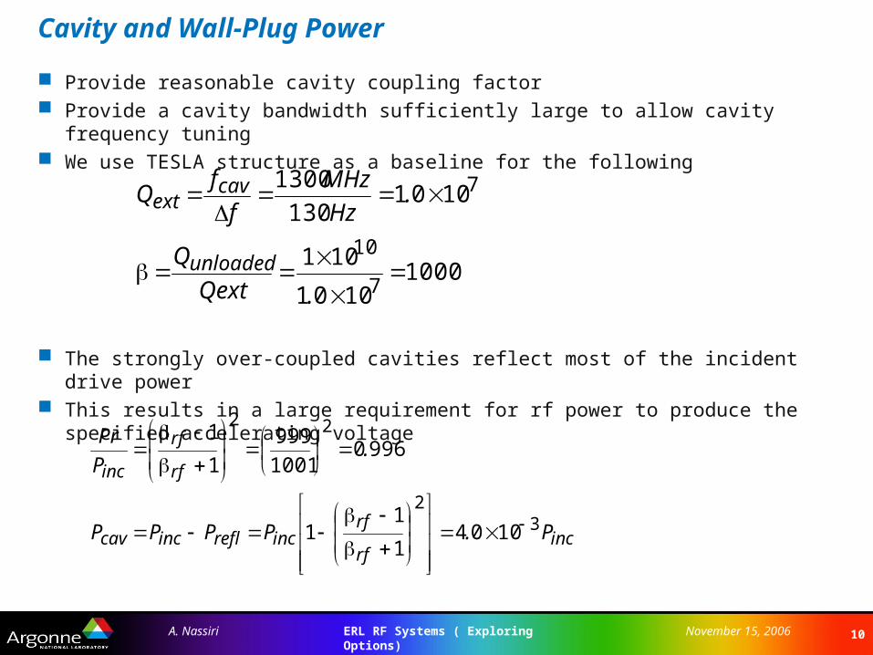
Provide reasonable cavity coupling factor Provide a cavity bandwidth sufficiently large to allow cavity frequency tuning We use TESLA structure as a baseline for the following
The strongly over-coupled cavities reflect most of the incident drive power This results in a large requirement for rf power to produce the specified accelerating
voltage
10001001
101
1001 130
1300
7
10
7
.Qext
Q
.Hz
MHz
f
fQ
unloaded
cavext
incrf
rfincreflinccav
rf
rf
inc
P.PPPP
.P
Pr
32
22
10041
11
99601001
999
1
1
11ERL RF Systems ( Exploring Options)A. Nassiri November 15, 2006
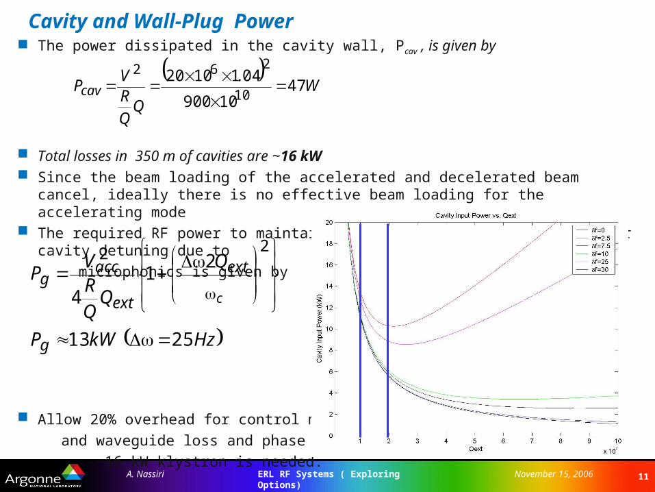
Cavity and Wall-Plug Power The power dissipated in the cavity wall, Pcav , is given by
Total losses in 350 m of cavities are ~16 kW Since the beam loading of the accelerated and decelerated beam cancel, ideally there is no
effective beam loading for the accelerating mode The required RF power to maintain a given accelerating voltage under cavity detuning due to
microphonics is given by
Allow 20% overhead for control margin
and waveguide loss and phase shift
~16 kW klystron is needed.
W
.
RV
Pcav 4710900
041102010
262
HzkWP
Q
RV
P
g
ext
ext
accg
c
25 13
21
4
22
12ERL RF Systems ( Exploring Options)A. Nassiri November 15, 2006
Cavity and Wall-Plug Power
The required rf power will increase to ~17 kW if one operate the TESLA cavity at the design gradient of 23 MV/m
APS-ERL requires ~350 cavities ( ~350m effective accelerating length) Assuming an IOT efficiency of 65% The wall-plug power for the 7 GeV ERL is 7.0 MW Injector beam power ( 100 mA @10 MeV) is 1MW. 1MW of CW RF power
is required Assuming a klystron efficiency of 50% Injector wall-plug power is 2 MW Losses due to synchrotron radiation ( ~15 MeV) ~1.5 MW Total wall-plug power is 11.5 MW Multi-pass recirculation reduces wall-plug power
13ERL RF Systems ( Exploring Options)A. Nassiri November 15, 2006
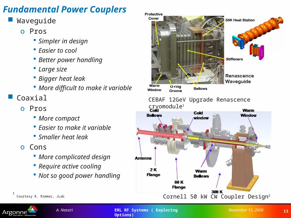
Fundamental Power Couplers Waveguide
o Pros Simpler in design Easier to cool Better power handling Large size Bigger heat leak More difficult to make it variable
Coaxial
o Pros More compact Easier to make it variable Smaller heat leak
o Cons More complicated design Require active cooling Not so good power handling
Cornell 50 kW CW Coupler Design2
CEBAF 12GeV Upgrade Renascence cryomodule1
1 Courtesy R. Rimmer, JLab
2 Courtesy M. Liepe, Cornell
14ERL RF Systems ( Exploring Options)A. Nassiri November 15, 2006
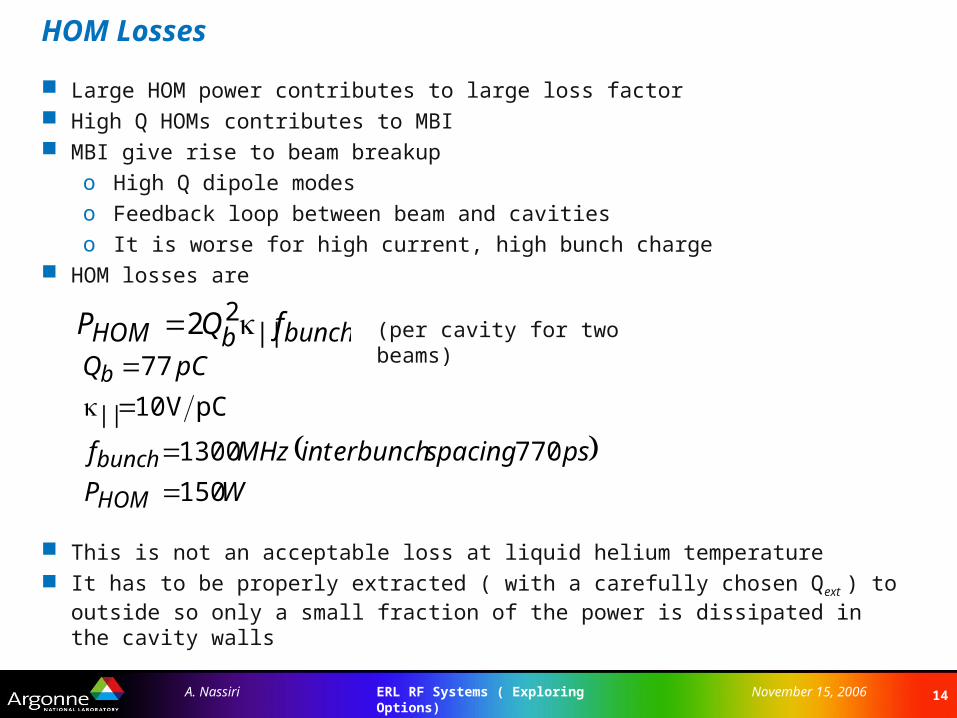
HOM Losses
Large HOM power contributes to large loss factor High Q HOMs contributes to MBI MBI give rise to beam breakup
o High Q dipole modeso Feedback loop between beam and cavitieso It is worse for high current, high bunch charge
HOM losses are
This is not an acceptable loss at liquid helium temperature It has to be properly extracted ( with a carefully chosen Qext ) to outside so only a small
fraction of the power is dissipated in the cavity walls
bunch||bHOM fQP 22
WP
psspacingerbunchintMHzf
pCQ
HOM
bunch
||
b
150
770 1300
pCV 10
77
(per cavity for two beams)
15ERL RF Systems ( Exploring Options)A. Nassiri November 15, 2006
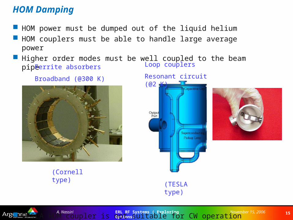
HOM Damping
HOM power must be dumped out of the liquid helium HOM couplers must be able to handle large average power Higher order modes must be well coupled to the beam pipe
TESLA HOM coupler is not suitable for CW operation
Ferrite absorbers
Broadband (@300 K)
Loop couplers
Resonant circuit (@2 K)
(Cornell type)
(TESLA type)

16ERL RF Systems ( Exploring Options)A. Nassiri November 15, 2006
Cooling Requirements for 7 GeV
APS-ERL will require a cryogenic plant equivalent to 3.5 x CEBAF Electrical power utilities requirement: 16.0 MW ( operating at 2.08 ºK) Multi-pass recirculation reduces power requirement
Cavity frequency (MHz) 1300 1300 704 704
Gradient 15 MV/m 20 MV/m 15 MV/m 20 MV/m
Vcav (MV) 15.6 20.8 15.8 21
Number of cavities 448 337 443 333
Heat/cavity@Q0 1010 (W) 28 47 41 74
Dynamic heat (kW) 13.0 16.0 18.0 24
17ERL RF Systems ( Exploring Options)A. Nassiri November 15, 2006
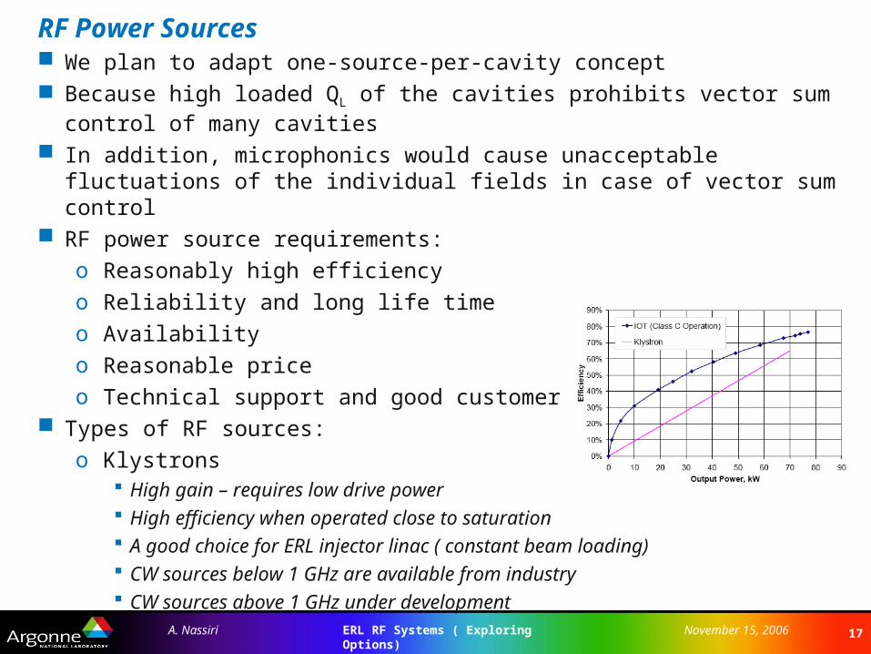
RF Power Sources We plan to adapt one-source-per-cavity concept Because high loaded QL of the cavities prohibits vector sum control of many
cavities In addition, microphonics would cause unacceptable fluctuations of the individual
fields in case of vector sum control RF power source requirements:
o Reasonably high efficiency
o Reliability and long life time
o Availability
o Reasonable price
o Technical support and good customer service Types of RF sources:
o Klystrons High gain – requires low drive power High efficiency when operated close to saturation A good choice for ERL injector linac ( constant beam loading) CW sources below 1 GHz are available from industry CW sources above 1 GHz under development
18ERL RF Systems ( Exploring Options)A. Nassiri November 15, 2006
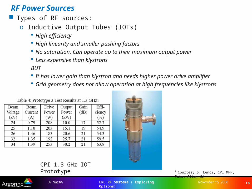
RF Power Sources Types of RF sources:
o Inductive Output Tubes (IOTs) High efficiency High linearity and smaller pushing factors No saturation. Can operate up to their maximum output power Less expensive than klystrons
BUT It has lower gain than klystron and needs higher power drive amplifier Grid geometry does not allow operation at high frequencies like klystrons
CPI 1.3 GHz IOT Prototype1 Courtesy S. Lenci, CPI MPP, Palo, Alto, CA
1
19ERL RF Systems ( Exploring Options)A. Nassiri November 15, 2006
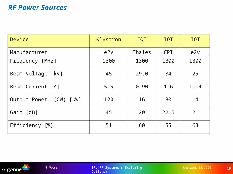
RF Power Sources
Device Klystron IOT IOT IOT
Manufacturer e2v Thales CPI e2v
Frequency [MHz] 1300 1300 1300 1300
Beam Voltage [kV] 45 29.0 34 25
Beam Current [A] 5.5 0.90 1.6 1.14
Output Power (CW) [kW] 120 16 30 14
Gain [dB] 45 20 22.5 21
Efficiency [%] 51 60 55 63
20ERL RF Systems ( Exploring Options)A. Nassiri November 15, 2006
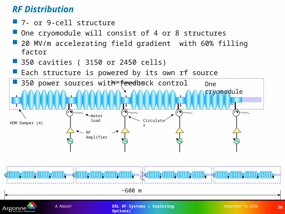
RF Distribution 7- or 9-cell structure One cryomodule will consist of 4 or 8 structures 20 MV/m accelerating field gradient with 60% filling factor 350 cavities ( 3150 or 2450 cells) Each structure is powered by its own rf source 350 power sources with feedback control
HOM Damper (4)
HOM Damper (4)
RF Amplifier
Water loadCirculator
One cryomodule
~600 m
21ERL RF Systems ( Exploring Options)A. Nassiri November 15, 2006
LLRF Control Requirements Maintain constant phase and amplitude of the cavity fields within given
tolerances
o RF phase: 0.050 RMS
o RF amplitude: 1x10⁻⁴ RMS Minimize power needed for control by actively controlling cavity tuners to
ensure operation on resonance Build-in diagnostics for calibration of gradient and phase, cavity detuning Fast interlock system for faults during a cavity trip Feedback loops and control to deal with:
o Beam current fluctuations
o Microphonics
o Lorentz force detuning Possible types of control systems:
o Self-excited loop
o Generator driven system and monitor separate amplitude and phase
o Use I/Q detector and controller
o FPGA/DSP Use JLab, SNS, CORNELL LLRF systems as baseline design
22ERL RF Systems ( Exploring Options)A. Nassiri November 15, 2006
Cavity R&D Active R&D is needed to address critical SCRF cavity design for CW operation
o Investigate the need for the development of a new cavity that meets APS ERL requirements Higher fill factor Strong HOM damping Low microphonics TESLA, JLab, Cornell, and BNL experiences are essential
o Optimize the shape of the Cornell 7-Cell cavity to further increase HOM damping and to lower cryogenic losses Collaborate with Cornell SCRF group
o Design and build a prototype multi-cell copper cavity Measure fundamental rf parameters
• Q’s of fundamental and HOM modes
Bead-pull measurements to check field flatness Identify the HOM modes from bead pull field profile
o Analysis and simulation of HOM and damping o Design of a high power input coupler (FPC)
Use JLab WG coupler and TESLA Coaxial coupler as baseline
o Design and build a multi-cell Nb first prototype cavityo Design and build a prototype cryomoduleo Perform vertical dewar test
23ERL RF Systems ( Exploring Options)A. Nassiri November 15, 2006
Conclusion SCRF technology for ERLs and CW machines is advancing at a fast pace We expect cavities development to make possible to operate at energy gains in
excess of 20 MV/m A wide range of expertise and experience already exists Our challenge is to:
o How to deal with a 16 kW cryogenic plant ( big footprint, capital+operation) Note: CEBAF CHL system is 4.6 kW @ 2.1 K
o Design a CW-specific cavity to meet ERL design parameters Tesla 9-cell and JLab 7-cell structures are good candidates
o Develop a robust HOM damping system
o Better understand and reduce field emission for higher gradient in CW mode
o Improve cavity quality factor ( 11011 !) For CW operation highest fields are not important. Highest possible Q values at
about 20 MV/m are very critical. This is in contrast with pulsed ILC requirement.
o Develop a robust LLRF control system for CW operation We intend to actively seek collaboration with other laboratories and institutions
on the development of SCRF for ERL ( JLab, Cornell, BNL, Daresbury,….)