erl sessions bettina kuske and susan smith + joint session convenors + contributing speakers
TRANSCRIPT
ERL Sessions
Bettina Kuske and Susan Smith+
Joint Session Convenors+
Contributing Speakers
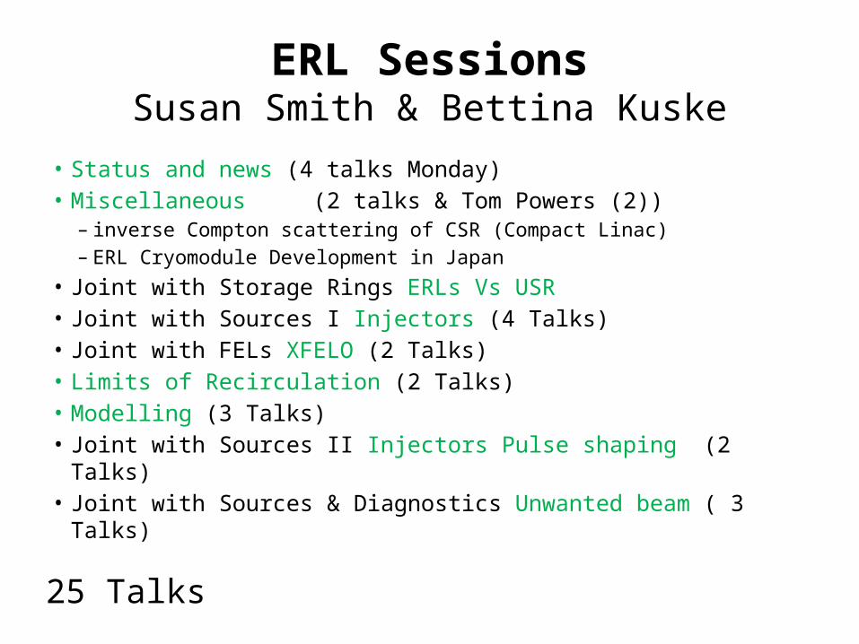
ERL SessionsSusan Smith & Bettina Kuske
• Status and news (4 talks Monday)• Miscellaneous (2 talks & Tom Powers (2))
– inverse Compton scattering of CSR (Compact Linac)– ERL Cryomodule Development in Japan
• Joint with Storage Rings ERLs Vs USR • Joint with Sources I Injectors (4 Talks)• Joint with FELs XFELO (2 Talks)• Limits of Recirculation (2 Talks)• Modelling (3 Talks)• Joint with Sources II Injectors Pulse shaping (2 Talks)• Joint with Sources & Diagnostics Unwanted beam ( 3 Talks)
25 Talks
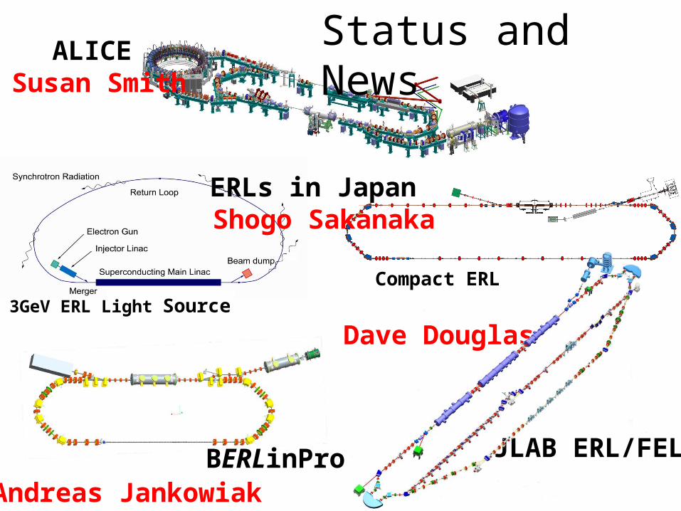
ALICESusan Smith
Compact ERL 3GeV ERL Light Source
ERLs in JapanShogo Sakanaka
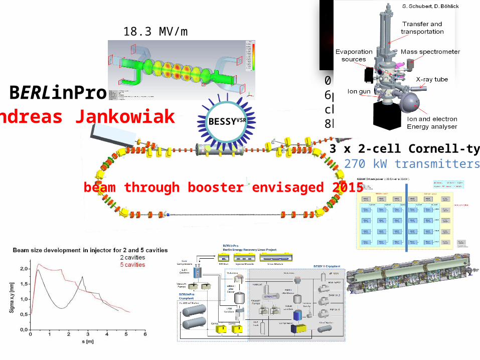
BERLinProAndreas Jankowiak
JLAB ERL/FELs
Dave Douglas
Status and News

• THz beamline– ~10s of W @ 0.2 – 1.5 THz
• IR FEL– High power FEL, optics, beam dynamics studies– 14+ kW at 1.6 microns; several kW @ multiple
wavelengths• UV FEL
– Recently commissioned (summer 2010)– High power (100+W) CW 700, 400 nm– Coherent harmonics into VUV (10 eV)
Now lasing CW again in the IR
DC Gun
SRF Lin
ac
Dump
IR W
iggl
er
Bunch
ing
Chica
ne
E
f
E
f
E
f
E
f
E
f
E
f
Sextupoles(B’dL) 10730 G
Sextupoles(B’dL) 12730 G
Sextupoles(B’dL) 8730 G
JLab IR Demo Dump
core of beam off center, even though BLMs showed edges were centered
(high energy tail
JLAB ERL/FELsDave Douglas
Machine overhaul, upgrade during next long shutdown
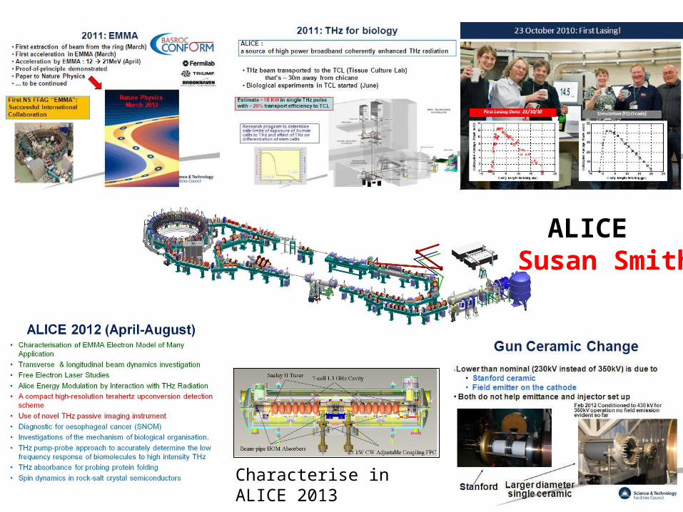
Characterise in ALICE 2013
ALICESusan Smith
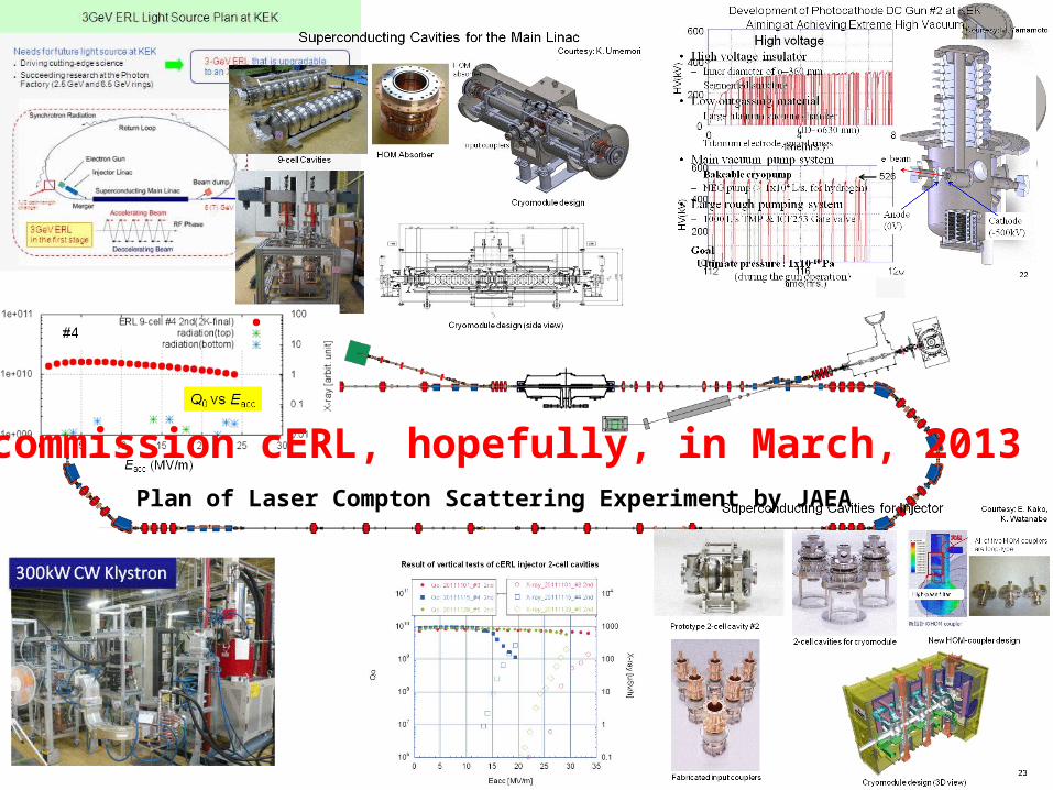
Plan of Laser Compton Scattering Experiment by JAEA
commission cERL, hopefully, in March, 2013
First beam21st April 2011
0. 1.8MeV6pC bunch charge8kHz (~50nA)
BESSYVSR
18.3 MV/m
3 x 2-cell Cornell-type270 kW transmitters
beam through booster envisaged 2015
BERLinProAndreas Jankowiak

Compact ERLEarthquake proof
ERL SHIELDING @ 100 mA
BERLinPro Radiation regulatory body proof
BESSY II: 200mC / a @ 1.7GeV typicalBERLinPro: some 100mC / 1s @ 50 MeV possible (30kW linac RF-power)
Miscellaneous
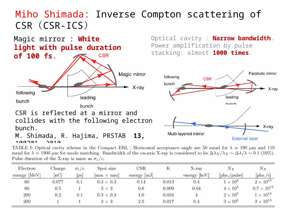
CSR is reflected at a mirror and collides with the following electron bunch.M. Shimada, R. Hajima, PRSTAB 13, 100701, 2010
Miho Shimada: Inverse Compton scattering of CSR(CSR-ICS)
Optical cavity : Narrow bandwidth. Power amplification by pulse stacking: almost 1000 times.
Magic mirror : White light with pulse duration of 100 fs.
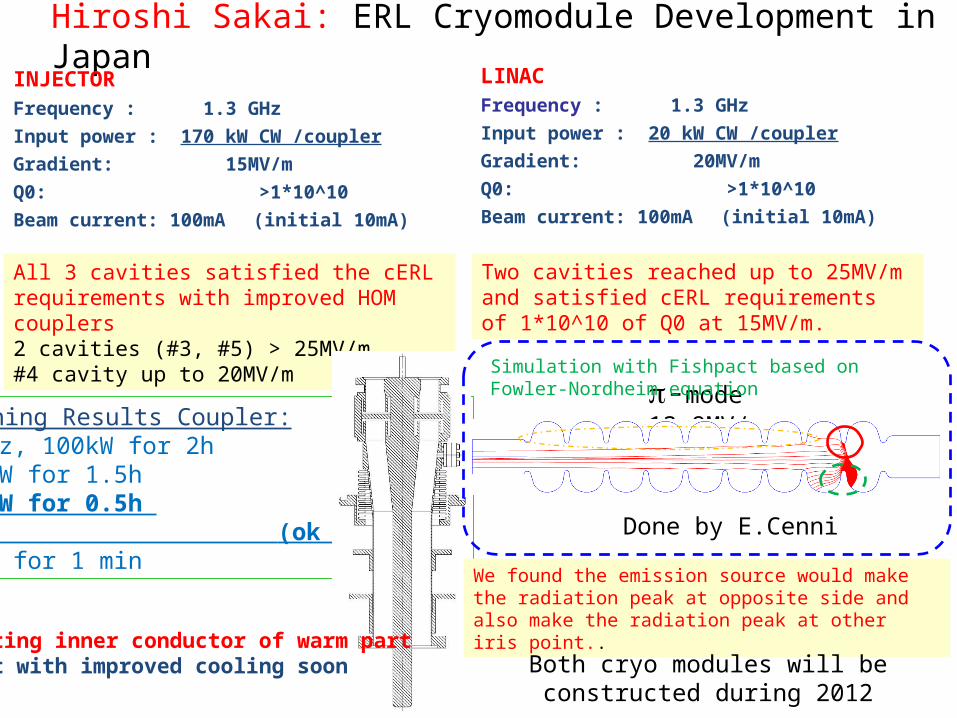
Hiroshi Sakai: ERL Cryomodule Development in JapanINJECTORFrequency : 1.3 GHz
Input power : 170 kW CW /coupler
Gradient: 15MV/m
Q0: >1*10^10
Beam current: 100mA (initial 10mA)
All 3 cavities satisfied the cERL requirements with improved HOM couplers2 cavities (#3, #5) > 25MV/m #4 cavity up to 20MV/m
Conditioning Results Coupler:• 1s, 0.1Hz, 100kW for 2h• cw 30kW for 1.5h• cw 50kW for 0.5h (ok for 10mA)• cw 100kW for 1 min
Heating inner conductor of warm partTest with improved cooling soon
LINACFrequency : 1.3 GHz
Input power : 20 kW CW /coupler
Gradient: 20MV/m
Q0: >1*10^10
Beam current: 100mA (initial 10mA)
-mode 13.9MV/m
t
Simulation with Fishpact based on Fowler-Nordheim equation
We found the emission source would make the radiation peak at opposite side and also make the radiation peak at other iris point..
Done by E.Cenni
Two cavities reached up to 25MV/m and satisfied cERL requirements of 1*10^10 of Q0 at 15MV/m.
Both cryo modules will be constructed during 2012

Tom Powers Cost Calculator
Inputs
gradient 1.80E+07current
(A)1.00E-01
RF PWR
margin1.3
Cryo margin
1.5Machine Energy
2Linac
packing factor
1.25Microph
onics10
Total $3,464M $3,436M $1,212M $1,181M $693M $3,558M $3,433M $3,554M $3,424M
Relative capital costs1.00 0.99 0.35 0.34 0.20 1.03 0.99 1.03 0.9910 year Operating Costs ($M)$36M $24M $34M $34M $20M $21M $23M $19M $20MTotal cost 10 years ($M)$3,500M $3,460M $1,246M $1,215M $713M $3,579M $3,456M $3,573M $3,444M
Relative Cost 1.00 0.99 0.36 0.35 0.20 1.02 0.99 1.02 0.98

Joint session with storage rings:Christof Steier / Ivan Bazarov: USR versus ERL Comparison and potential synergiesBenefits of USR has a strong orientation towards typical ERL features: short
pulses, high coherence, round beams, flexible operation modes, reduced no. of turns
Special operating modes:– Single/few-turn, sub-ps bunch mode– Crab cavity short pulse scheme (shorter bunches plus smaller emittance might allow much shorter pulses compared to SPX)– 100-1000 turn mode, enabling very low emittance with reduced dynamic aperture, requiring injection of fresh electrons from a superconducting linac operating withoutenergy recovery (e.g. ~1 mA @ few GeV)– localized bunch compression systems with components located in long straight sections– bunch tailoring with low alpha, non linear momentum compaction, multiple RF frequencies– lasing in an FEL located in a switched bypass, where the post-lasing electron bunchesare returned to the storage ring for damping– partial lasing at soft X-ray wavelengths using the stored beam, requiring high peakcurrent created by localized bunch manipulation
USR lattices and optimization procedures become highly complex, but using existing technologiesERLs just start off and future potentials will develop after ‘generation 1’ goes online

Joint session:Sources I- Injectors for ERLs
Three areas future collaboration1. Emittance and longitudinal bunch properties vs
charge2. Operating cathode lifetime and integrated
charge per cathode intervention3. Field emission
– Removal methods (HV, wiping, gas processing & others)– Characterisation (location, causes etc.)
50 mA record and 35 mA sustainable (Cornell)
Andrew Burrill Requirements and first ideasInjector development BERLinPro T. Kamps SRF gun – beam studies with Pb cathode
KEK T. Miyajima DC gun reached > 500kV JAEA N. Nishimori DC gun reached > 500kV
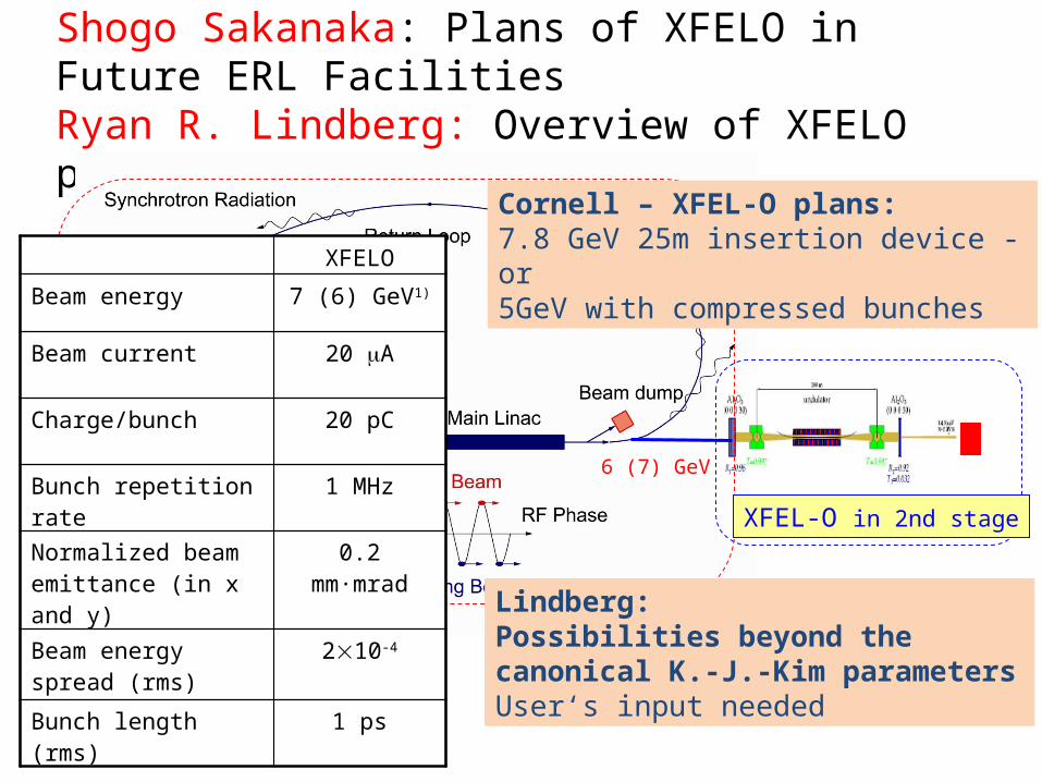
Joint session with FEL: XFELO Shogo Sakanaka: Plans of XFELO in Future ERL FacilitiesRyan R. Lindberg: Overview of XFELO parameters
6 (7) GeV
3GeV ERLin the first stage
XFEL-O in 2nd stage
lrf/2 path-lengthchanger
XFELO
Beam energy 7 (6) GeV1)
Beam current 20 mA
Charge/bunch 20 pC
Bunch repetition rate 1 MHz
Normalized beam emittance (in x and y)
0.2 mm·mrad
Beam energy spread (rms)
210-4
Bunch length (rms) 1 ps
Cornell – XFEL-O plans:7.8 GeV 25m insertion device - or5GeV with compressed bunches
Lindberg:Possibilities beyond the canonical K.-J.-Kim parametersUser‘s input needed

Effects of Several VLong Undulatorsin the APS ERL Design
The impact of undulators in 4GLS
Limits of Recirculation
• 7 GeV, 9 x 48m undulators K=5, 55mm
• Energy shift 1.4 MeV noticeable• Use of booster cavities seems
advisable
• 600MeV, 10 m 1 T hel. Undulator
• Energy shift 4.6 keV negligible
M. Borland, G. Decker, X. Dong, L. Emery, A. Nassiri, Proc. PAC09, 44- (2009).
• Energy spread increase is fairly modest c.f. CSR increase
• Final energy spread of ~1.3 MeV with all gaps closed
• No emittance growth seen• Conclusion should be checked with
realistic optics errors (i.e., dispersion leaking into straight sections
• Negligible emittance growth• Negligible energy spread• CSR in arcs ~1MeV !• Path length change 300fs for long
undulator• Use path length chicane seems
advisable (feedforward)• Photon pulse lengthening due to long
undulator ~ 150 fs, 30fs short• Impact on beam dynamics in
general of the varying focussing and non-linear terms was not studied
(http://www.4gls.ac.uk/)
Mike Borland Jim Clarke
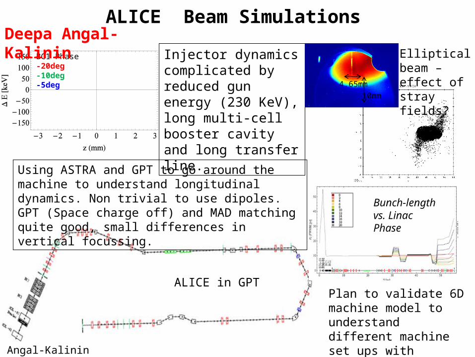
ALICE Beam Simulations
ALICE in GPT
BC1 Phase-20deg -10deg -5deg
Injector dynamics complicated by reduced gun energy (230 KeV), long multi-cell booster cavity and long transfer line.
Using ASTRA and GPT to go around the machine to understand longitudinal dynamics. Non trivial to use dipoles. GPT (Space charge off) and MAD matching quite good, small differences in vertical focussing.
4.65mm10mm
Elliptical beam – effect of stray fields?
Bunch-length vs. Linac Phase
Plan to validate 6D machine model to understand different machine set ups with additional diagnostics .
D. Angal-Kalinin
Deepa Angal-Kalinin

Miho Shimada: Lattice and optics design of both compact ERL and 3-GeV ERL projects
DecelerationAcceleration
• Injection / dump energy: 10 MeV, full energy: 3 GeV• Circumference ~2000 m, linac length : 470 m• 22 x 6 m short straight , 6 x 30 m long straight• 28 cryo modules, 8 x 9-cell cavities per cryo module• field gradient: 13.4 MV/m, focusing triplets• Deceleration symmetric to the acceleration• Achromatic and isochronous TBA optics in arcs r~20m
1 mm-mrad
5 mm-mrad
9 mm-mrad
• enx increases step by step at every each arc.– In the first inner loop : 1 mm-mrad– In the outer loop : 5 mm-mrad
• The low emittance beam is difficult for 2 loop ERL compared with 1 loop ERL

Yichao Jing: Bunch compressor design for FEL @ eRHIC
Studies for eRHIC FELChoose low energy (~ 10 GeV) for FEL to avoid severe blow up in both emittance and energy spread caused by synchrotron radiation. Normalized emittance assumed to be 0.2 μm in simulation.
Phase space plots show clear evidence of emittance spoil due to the longitudinal – transverse coupling in chicanes.
C-type chicane 1C-type chicane 2Opposite bending directionSmaller bending strength
Phase shifter
Reduction of emittance growth
Promising FEL performance
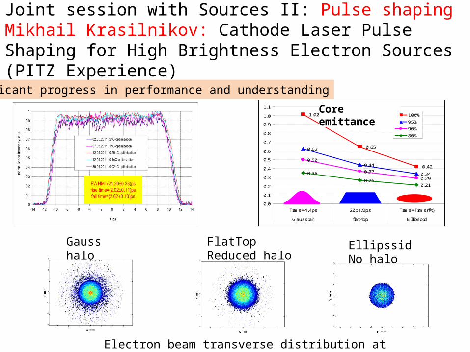
Joint session with Sources II: Pulse shapingMikhail Krasilnikov: Cathode Laser Pulse Shaping for High Brightness Electron Sources (PITZ Experience)
1.02
0.65
0.42
0.62
0.44
0.34
0.50
0.37
0.290.35
0.260.21
0.0
0.1
0.2
0.3
0.4
0.5
0.6
0.7
0.8
0.9
1.0
1.1
Trms=4.4ps 20ps/2ps Trms=Trms(f-t)
Gaussian flat-top Ellipsoid
100%
95%
90%
80%
Core emittance
Electron beam transverse distribution at z=5.74m
Gausshalo
FlatTopReduced halo
EllipssidNo halo
Significant progress in performance and understanding
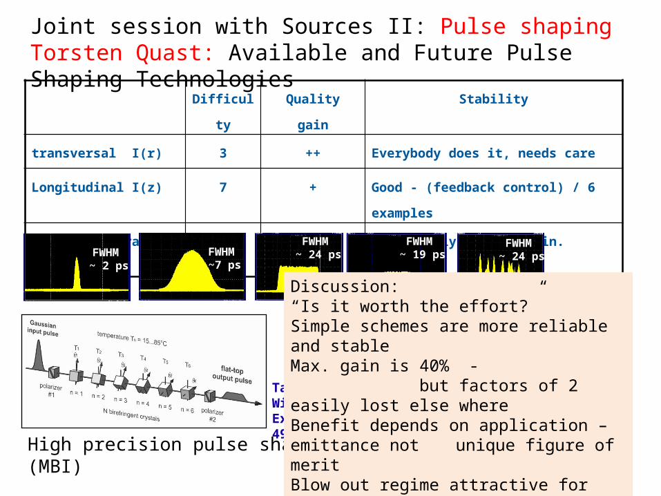
Joint session with Sources II: Pulse shapingTorsten Quast: Available and Future Pulse Shaping Technologies
Difficulty Quality gain Stability
transversal I(r) 3 ++ Everybody does it, needs care
Longitudinal I(z) 7 + Good - (feedback control) / 6 examples
spatio-temporal I{r(z)} 10 ? Poor – relying on nonlin. effects
High precision pulse shaper (MBI)
Taken from: Will, Klemz, Optics Express 16 (2008) , 4922-14935
FWHM ~7 ps
FWHM ~ 2 ps
FWHM ~ 24 ps
FWHM ~ 19 ps
FWHM ~ 24 ps
Discussion:“Is it worth the effort?”Simple schemes are more reliable and stableMax. gain is 40% - but factors of 2 easily lost else whereBenefit depends on application – emittance not unique figure of meritBlow out regime attractive for
halo reductioninsensitive towards laser parameters
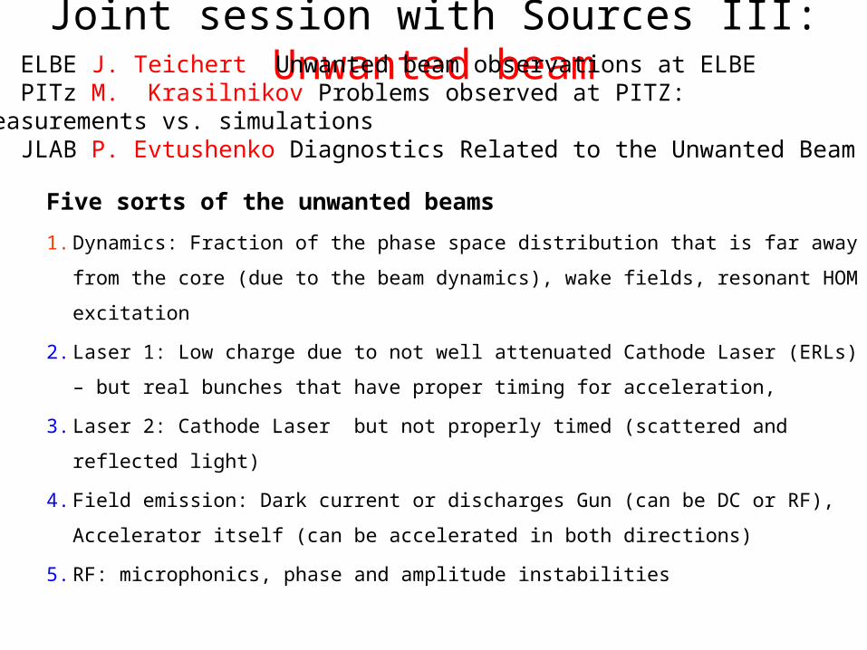
Joint session with Sources III: Unwanted beam
Five sorts of the unwanted beams
1. Dynamics: Fraction of the phase space distribution that is far away from the
core (due to the beam dynamics), wake fields, resonant HOM excitation
2. Laser 1: Low charge due to not well attenuated Cathode Laser (ERLs) – but real
bunches that have proper timing for acceleration,
3. Laser 2: Cathode Laser but not properly timed (scattered and reflected light)
4. Field emission: Dark current or discharges Gun (can be DC or RF), Accelerator
itself (can be accelerated in both directions)
5. RF: microphonics, phase and amplitude instabilities
ELBE J. Teichert Unwanted beam observations at ELBEPITz M. Krasilnikov Problems observed at PITZ: measurements vs. simulationsJLAB P. Evtushenko Diagnostics Related to the Unwanted Beam
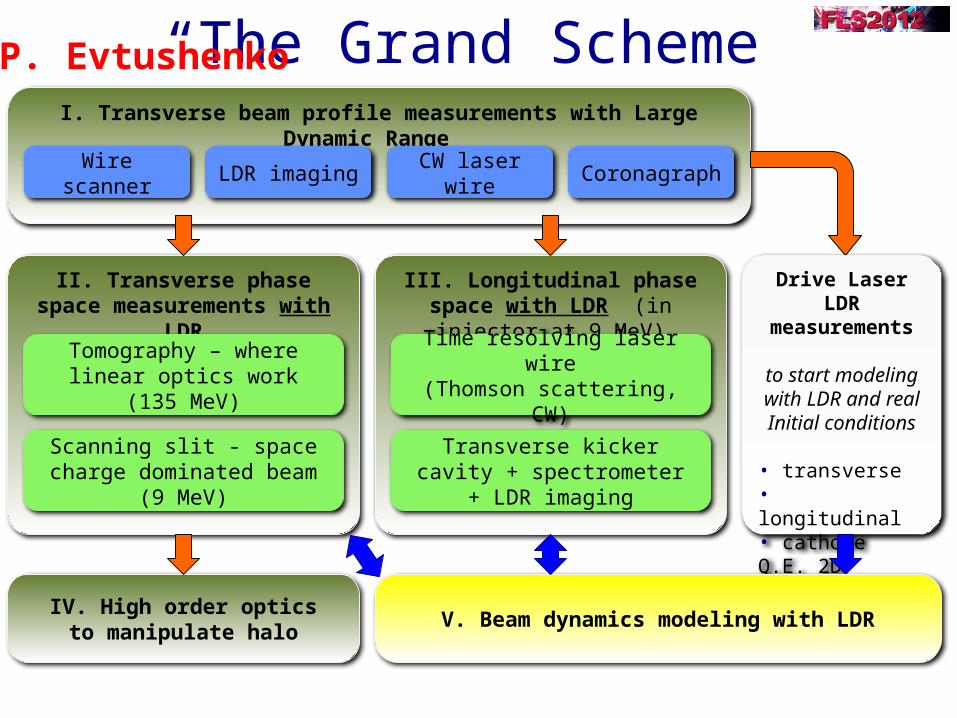
“The Grand Scheme”I. Transverse beam profile measurements with Large Dynamic Range
Wire scanner LDR imaging CW laser wire Coronagraph
II. Transverse phase space measurements with LDR
Tomography – where linear optics work (135 MeV)
Scanning slit - space charge dominated beam (9 MeV)
III. Longitudinal phase space with LDR (in injector at 9 MeV)
Time resolving laser wire(Thomson scattering, CW)
Transverse kicker cavity + spectrometer + LDR imaging
IV. High order opticsto manipulate halo
Drive Laser LDRmeasurements
to start modeling with LDR and realInitial conditions
• transverse • longitudinal• cathode Q.E. 2D
V. Beam dynamics modeling with LDR
P. Evtushenko
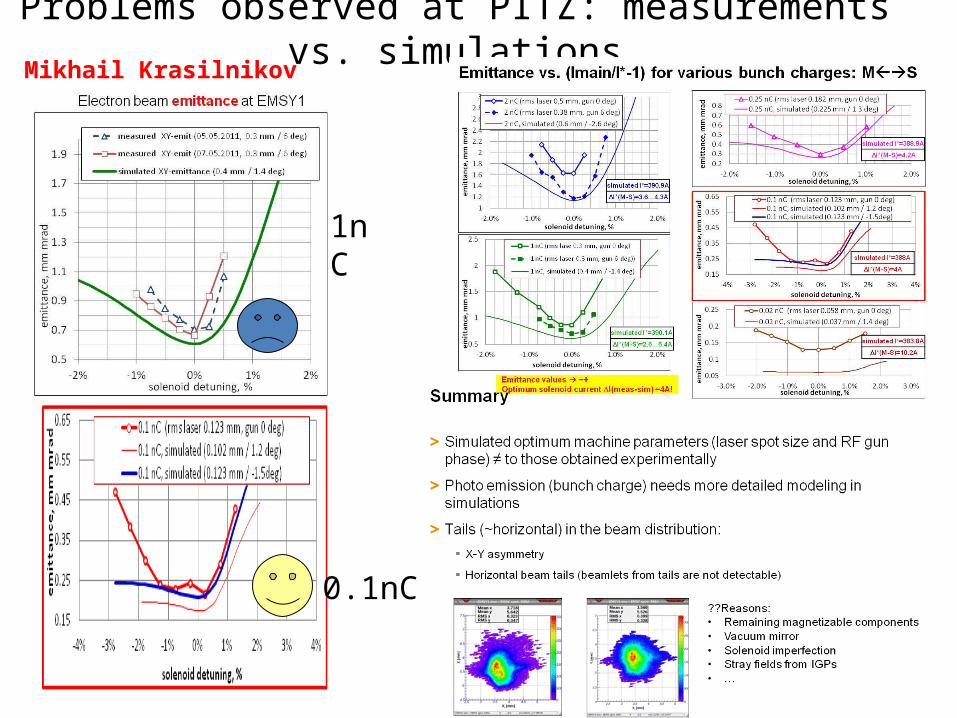
Problems observed at PITZ: measurements vs. simulations
1nC
0.1nC
Mikhail Krasilnikov

assuming an unwanted beam of < 1 µA in CW accelerators with SRF guns there will be a need for photo cathodes with low dark current
proper handling to prevent dust particles and damage
plug materials and roughness
photo layer properties - roughness, homogeneity, thickness - high work function - crystal size and structure - multi-layer design - post-preparation treatment (ions, heating) - pre-conditioning
20% Cathode (80% scratch on cavity)
courtesy ofF. Obier/DESY
Dark current kicker
Pulsed operation
bunch 100 pCdark current at 1.3 GHz
100 ms
10 ms
pulsed RF laser
10 ms
Unwanted Beam Observations at ELBE
J. Teichert