ermtgsrr_xxxxxxxxx · web viewultrasonic-only or ultrasonic+camera-fusion provides obstacle...
TRANSCRIPT

ERMTGSRR_XXXXXXXXX
Title*: Interference Testing for 76-81GHz Automotive Radars
from Source*: Magna ElectronicsContact: Wayne Stark, Helmut Wodrich, Gordon Woodington
input for Committee*: ERM TGSRR
Contribution For*: DecisionDiscussion XInformation
Submission date*: 2018-03-07
Meeting & Allocation: ERMTGSRR#32 Relevant WI(s), or
deliverable(s):
ABSTRACT: Simple Interference tests for current and future radar systems are proposed that are simple to perform and determines the performance in the presence of in-band interference.
Introduction:
The European Union Directive 2014/53EU states that
“In order to ensure that radio equipment uses the radio spectrum effectively and supports the efficient use of radio spectrum, radio equipment should be constructed so that: … in the case of a receiver, it has a level of performance that allows it to operate as intended and protects it against the risk of harmful interference, in particular from shared or adjacent channels, and, in so doing, supports improvements in the efficient use of shared or adjacent channels.”
Automotive radars, in order to satisfy the harmonization goals should be tested to demonstrate that the radars operate as intended, especially in the presence of interference. Tests that are simple to perform are desirable. Test that will emulate real world conditions in the next 5+ years are also desirable.
Radars are typically characterized by a probability of false alarm (sometimes called the false positive rate) and a probability of detection (sometimes called the true positive rate). The receiver operating characteristics (RoC) is a plot of the probability of detection versus the probability of false alarm. The different points on the curve arise from different thresholds for deciding the presence or absence of a target.
Previously [1] three tests were suggested as a possibility for satisfying the EU Commission requirement stated above. The first test was a “receiver empty test” in which the probability of false alarm was measured (i.e. no target and an empty anechoic chamber).The second test was a receiver sensitivity test in which the probability of detection was measured for a target at various distances.
1/13

ERMTGSRR_XXXXXXXXXThe third test was a receiver blocking test in which an interfering source was placed at the 3dB beam width of the transmitting signal. The electric field received at the device under test (DUT) was specified corresponding an interfering signal transmitting with power about 10dBm (EIRP) at a distance of 10m. The interfering source was an FMCW type of signal although the specific chirp bandwidth and chirp time were not specified. Various target sizes with radar cross sections from -10dBsm to +10dBsm at distances between 10m and 500m were chosen. There are many parameters to completely specify this test including the chirp bandwidth, the chirp time, time between chirps, time between frames in a sequence of chirps. These parameters are yet to be specified for the test and vary dependent on the specific feature use case.
Variations on this test could include varying the angle of the interference or could consider other modulation techniques including OFDM, PN, FSK, CW. These other types of interference are potential sources of future radar systems [1]. Each interferer could employ any one of a number of different modulation techniques, from different angles, with different power levels, with different parameters.
Future automotive radars might be subject to numerous types and sources of interference. As such, it is important to test for a composite of many different signals. Performing tests with a composite of many signals with targets at different distances and different angles, while complex, does likely represent the environment of the future. Market projections for future radar deployment have been included separately for consideration by TG-SRR#32. A simple alternative to specifying numerous parameters for multiple interferers would be a receiver blocking test using an interferer that is just bandlimited white Gaussian noise. Only a power level needs to be specified.
We propose the following additional tests:
A first additional test is just using a source that is a white Gaussian noise source with power density of -10dBm/MHz (.1mW/MHz) or a total of 500mW= over the total 76-81GHz frequency band. The transmitter will be located 10m 1m from the receiver at the 3dB beamwidth of the receiving antenna of the radar system. Various target sizes with radar cross sections from -10dBsm to +10dBsm at distances between 10m and 500m 250m were chosen, according to the radar type and mode declaration. The receiver will measure the probability of detection. Passing the test means that the estimated range of the target will be within +/- 5% of the actual range. Additionally, based on use case required parameters, passing should also include similar accuracy tests for all detection attributes used within feature software, trackers, etc.to achieve the intended use. These could include angular position detection in azimuth, or azimuth and elevation, magnitude of target and/or Doppler. As with the receiver sensitivity test and receiver empty test, 1000 outputs should be generated and the number of detection events counted to estimate the probability of detection.
A second possible test is just using a source that is a continuous wave (CW), that is a sinusoidal signal. The CW interferer is at a distance of 10m 1m and has total power 10dBm. The frequency of the interferer shall be sequentially stepped (100 MHz) across the band of the frequency allocation under which the DUT operates.
2/13

ERMTGSRR_XXXXXXXXX A third proposed test is to have 6 interferers that are unsynchronized using different
modulation techniques with different parameters. Ideally the interference would come from multiple angles. For example, three interferers from one angle and another three interferers from a second angle. The modulation techniques should include those modulation techniques that the MOSARIM study considered possible for future radar systems. For FMCW type of modulation the chirp rates should be chosen to include fast FMCW (e.g. 10-50 μs chirp time) and slow FMCW (e.g >1 ms chirp time.). Similarly, for other modulation techniques, parameters that may be typical of future radar systems should be chosen. Power levels commensurate with the power levels for the other tests should be used.
All tests should be accomplished in a reproducible and/or shielded RF environment.
The proposed tests can be accomplished in a number of ways.
1) A vector signal generator (e.g. R&S SMW200A) can generate a low frequency FMCW or CW signal and then a frequency multiplier (e.g. R&S SMZ) can be used to generate the signal in the frequency range 76-81GHz as shown below. The frequency multiplier will generate signals in the appropriate frequency band.
[2)] A pulse sequence generator can be used to generate an arbitrary baseband signal and the results mixed to a sub-20GHz carrier. Then, an up-converter (not frequency multiplier) is needed to generate a 76-81GHz signal for arbitrary waveforms. However, for FMCW, CWfrequency and phase modulated signals a frequency multiplier can be usedis sufficient.
2)[3)] A dedicated noise source can be utilized to generate noise and upconverted. 3) The shielded environment can be accomplished by using a small shielded chamber. 4) For target generation a calibrated corner reflector or radar echo generator can be used (some
radar echo generators also allow to upconvert the interference signal with the inbuild RF upconverter in the frontend and IF input (e.g. R&S AREG100A) (see setup #2) ).
References:
[1] “The EU-funded research project MOSARIM Final Project Report,” December 2012.
3/13

ERMTGSRR_XXXXXXXXX[2] Michael Mahler, “Summary RX-Requirement Discussion,” ERMTGSRR(17)029016r1
[3] “Millimeter wave vehicular collision avoidance radars and radio communication systems for intelligent transport system applications” Recommendation ITU-R M. 1452-2, May 2012.
4/13

ERMTGSRR_XXXXXXXXX
Proposed Modification to 8.2.2
8.2.2 Requirements for in-band interfererClass Given target Given interferer CriterionUSRR RCS = -10dBsm @
10m55mV/m @ FMCW
50 % probability of detection (Note)
USRR RCS = -10dBsm @ 10m
55mV/m @ WGN 50 % probability of detection (Note)
USRR RCS=-10dBsm @10m
10mV/m each from 6 sources
50 % probability of detection (Note)
SRR RCS = 0dBsm @ 20m
55mV/m @ FMCW
50 % probability of detection (Note)
SRR RCS = 0dBsm @ 20m
55mV/m @ WGN 50 % probability of detection (Note)
SRR RCS = 0dBsm @ 20m
10mV/m each from 6 sources
50 % probability of detection (Note)
MRR RCS = 10dBsm @ 50m
55mV/m @ FMCW
50 % probability of detection (Note)
MRR RCS = 10dBsm @ 50m
55mV/m @ WGN 50 % probability of detection (Note)
MRR RCS = 10dBsm @ 50m
10mV/m each from 6 sources
50 % probability of detection (Note)
LRR RCS = 10dBsm @ 150m
55mV/m @ FMCW
50 % probability of detection (Note)
LRR RCS = 10dBsm @ 150m
55mV/m @ WGN 50 % probability of detection (Note)
LRR RCS = 10dBsm @ 150m
10mV/m each from 6 sources
50 % probability of detection (Note)
Super LRR RCS = -10dBsm @ 500m
55mV/m @ FMCW
50 % probability of detection (Note)
Super LRR RCS = -10dBsm @ 500m
55mV/m @ WGN 50 % probability of detection (Note)
Super LRR RCS = -10dBsm @ 500m
10mV/m each from 6 sources
50 % probability of detection (Note)
Note: How many “EUT output update rates” show the given target at the given distance with an accuracy of up to +/- 5%.
The field strength of 55mV/m corresponds to a transmit power level of approximately 10dBm at a distance of 10m with an interfering antenna gain of 0dB. Alternatively, a horn antenna with 25dB gain can be used with a source generating -15dBm power at 10 meters or -21dBm at 5 meters. A field strength of 10mV/m corresponds to a transmit power level of approximately -4.77dBm at a distance of 10m with an interfering antenna gain of 0dB.
The six sources can be generated at two different angles relative to bore sight of the DUT.
Discussion point: If such long measuring distances are not possible within a certified test environment, then scaled down distances and scaled down RCS, or target simulators can be used.
Further test details: Check for given interferer parameters whether declared RF 1dB compression point is reached.
Check for given interferer parameters whether declared LF clipping point is reached.
5/13

ERMTGSRR_XXXXXXXXX
A.1 – Advanced Driving Assistance Systems: descriptions of features & use parameters
Function Key System Elements
Feature Description
Adaptive Light Control Matrix LED Lighting, RadarCameraLocalization
Matrix lighting is adapted based on inputs from ADAS sensors to control illumination on oncoming traffic, while providing maximum lamination for roadway, road signs, intersections or points of interest.Closed loop illumination control of traffic signs, etc. to achieve optimum illumination to enhance FCM detection potential. Blanking, shaping, highlighting, adaptive aiming and path planning potential.
Forward Collision Warning CameraRadar
Forward Collision Warning provides a early warning to the driver of a potential collision risk, prompting action by the driver to mitigate the risk. Ignoring the warning, causes the AEB function to be activated, where equipped.
Automatic Emergency Braking CameraRadarBraking Control
AEB alerts drivers to collisions with vehicles in their path. If they do not react to the alerts, it automatically brakes to mitigate or avoid a collision. This can be demonstrated two ways: 1) camera only and 2) fusion of a camera and RADAR.
Automatic Cruise Control (ACC) CameraRadarBraking Control
ACC is normally used under highway conditions and in essence, is a system which maintains a constant distance or time to a lead vehicle when the vehicle is
6/13

ERMTGSRR_XXXXXXXXXon highway (road where non-motorised vehicles and pedestrians are prohibited). In combination with Front Corner Radar, Pedestrian & VRU (Vulnerable Roadway User with AEB, LKA features, urban scenarios above 30 kph are supported.
Traffic Sign Recognition / Intelligent Speed Control
Camera Navigation dataBraking Control
The traffic sign and traffic light recognition system provides advisory, warning or intervention actions based on inputs from the detected signs or traffic lights. The source of information shall be an electronic map data with a system that can read the actual road signs. The combination of both technologies, apart from scoring more points in NCAP, shall be a reliable source of information for a variety of other functionalities, e.g. bend speed warning, temporary roadworks and for areas where mapping has not yet been undertaken (e.g. new road builds). The traffic light functionality shall be an optical based system.
Enhanced Blind Spot Monitoring Radar,Camera
Enhanced blind spot monitoring is a convenience feature, providing the driver with a warning, typically located in the rearview mirror, for vehicles in the blind spot zone or quickly approaching the vehicle. Coverage includes merging scenarios, with the incorporation of lane marking information. Vehicles approaching in the adjacent lane are reported up to 30m behind the vehicles (10m/s closing speed maximum). Where Lane Keep Assist is included, steering counter torque will be provided to the driver, providing an indication that a lane
7/13

ERMTGSRR_XXXXXXXXXchange is not recommended. The driver always maintains control of the decision to change lanes.
Lane Keep Assist Camera,Steering &/or Braking Control
EYERIS® solutions for lane detection are optimized for every kind of lane marking, thus providing a reliable performance in every market and every corner of the world. EYERIS® features either signal a warning to the driver prior to lane departure or automatically intervene with the car’s controls to deter the driver from moving out of their lane.
Lane Change Assist Front CameraCorner Radar
Lane Change Assist and cross traffic alert system extended the warning zone to support warnings at up to 70m behind the vehicle or in crossing traffic situations. Required to support high speed overtaking for European Autobahn scenarios and performance exceeding NHTSA NCAP BSD requirement.
Traffic Jam Assist Camera RadarCorner RadarLidarSteering &/or Braking Control
ACC is normally used under highway conditions and in essence, is a system which maintains a constant distance or time to a lead vehicle when the vehicle is on highway (road where non-motorised vehicles and pedestrians are prohibited). Traffic Jam Assist acts in combination with Front Corner Radar, LiDAR, Pedestrian & VRU (Vulnerable Roadway User with AEB, LKA features, in urban scenarios to provide full speed range ACC capabilities including Stop & Go traffic. The system maintains the current driving lane, permitting the driver to complete lane changes.
Rear Cross Traffic Alert Corner Radar, Rear Camera, UPA,
Backing in a busy shopping mall parking lot (cars, shopping carts, pedestrians
8/13

ERMTGSRR_XXXXXXXXXSVS,Braking Control
walking), the cross traffic alert system scans for traffic, pedestrians and range to surrounding objects. The driver is issued warnings via a mirror icon. In combination with Rear Pedestrian AEB, an expanded range of coverage is realized with the fusion of UPA, SVS and corner radar for enhanced security.
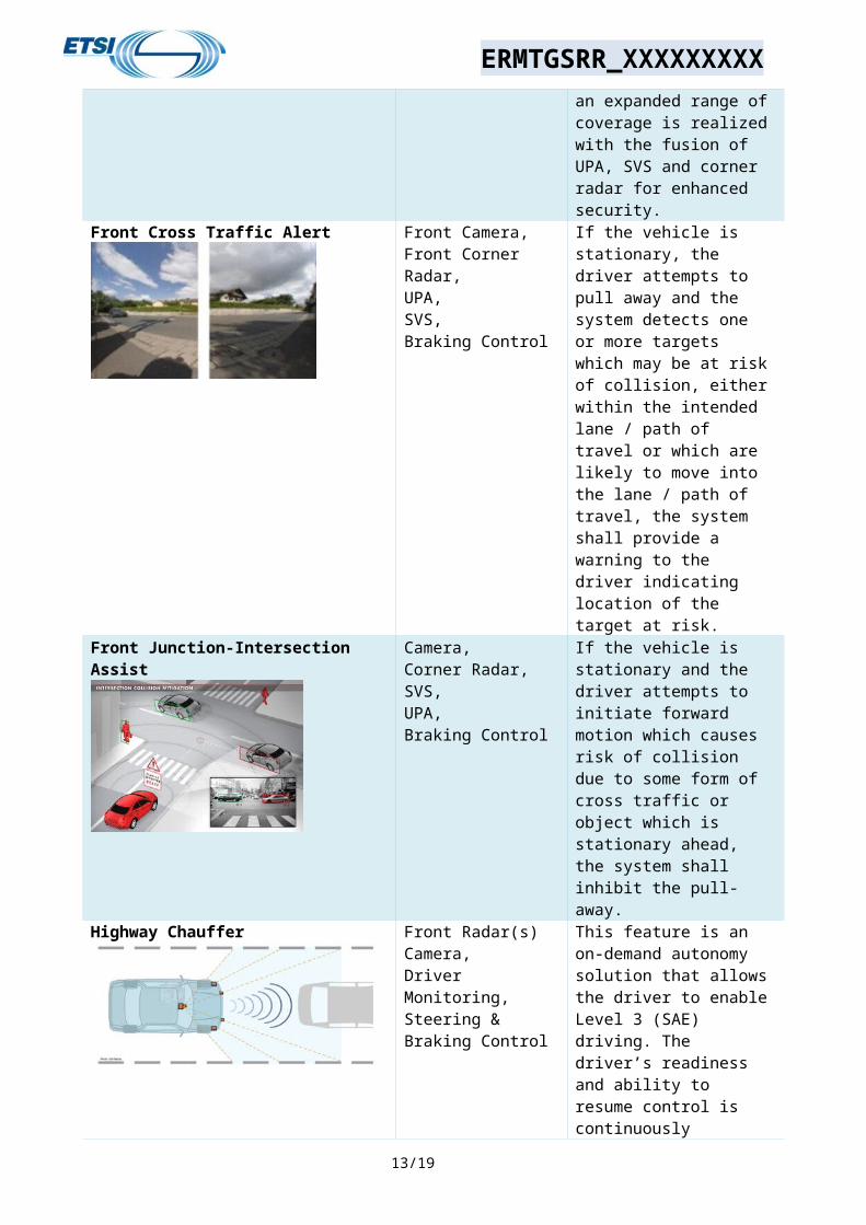
Front Cross Traffic Alert Front Camera, Front Corner Radar, UPA, SVS,Braking Control
If the vehicle is stationary, the driver attempts to pull away and the system detects one or more targets which may be at risk of collision, either within the intended lane / path of travel or which are likely to move into the lane / path of travel, the system shall provide a warning to the driver indicating location of the target at risk.
Front Junction-Intersection Assist Camera, Corner Radar, SVS,UPA,Braking Control
If the vehicle is stationary and the driver attempts to initiate forward motion which causes risk of collision due to some form of cross traffic or object which is stationary ahead, the system shall inhibit the pull-away.
Highway Chauffer Front Radar(s)Camera, Driver Monitoring,Steering & Braking Control
This feature is an on-demand autonomy solution that allows the driver to enable Level 3 (SAE) driving. The driver’s readiness and ability to resume control is continuously monitored. The driver is required to monitor the driving task, and when requested to take back control, they will be given 3 seconds to do so.Highway Chauffer handles all required driving on limited access highways with driver supervision. It handles lane management, speed modulation, and path planning.
Rear – Auto Emergency Braking UPA, Ultrasonic-only or
9/13

ERMTGSRR_XXXXXXXXXRear Camera,Radar,Braking Control
ultrasonic+camera-fusion provides obstacle detection and evaluation for Rear Automatic Emergency Braking (Rear AEB). The feature will automatically brake in case an object is in the path of the vehicle supporting NCAP requirements. Detection of the entire FMVSS 111 and NCAP reduces harsh emergency braking by providing control of rear backing speeds & comfort stops
Automatic Lane Change Camera360° Radar,Steering & Braking Control
Automated Lane Change Assist supplements ACC function to autonmously initiate and execute an overtaking manuever. System anticipates the need for overtaking manuever, monitors the driving situation and available opportunities to change lanes, selects the desired opportunity, initiates turn signal, changes lanes & adjusts speed to match the traffic flow. Automatically returns to the original lane after passing the preceeding vehicle.
Automated Parking Assist (APA) UPA,SVSSteering Control,Braking Control
Ultrasonic-only or camera+ultrasonic-fusion automated parking systems detects obstacles in the vehicle’s path, open parking spots and performs parallel or perpendicular parking maneuvers to park the car automatically. In combination with obstacle detection, the Rear Automatic Emergency Braking (Rear AEB) feature will automatically brake in case an object is in the path of the vehicle supporting NCAP requirements.
Home Zone Automated Parking (HZAP) Secure Connectivity, UPA, SVS,RadarSteering & Braking Control
An Ultrasonic or UPA+Vision fusion system for assisting the driver by automating the repetitive tasks such as parking in/out of known (learned) parking
10/13

ERMTGSRR_XXXXXXXXXspots. Once the desired spot and the associated approach are stored through a short learning/training session, HZAP system will maneuver the vehicle autonomously to a memorized parking spot
Valet Parking Secure Connectivity,Camera, 360° Radar, UPA, LiDARSteering & Braking Control
The driver exits the vehicle at a drop-off area and uses a remote control system, such as a fob or smart phone application, to send the vehicle away to park itself. The driver has no further interaction with the vehicle and the vehicle parks itself in a suitable parking location. The space is allocated by a carpark control system. After some time, either predefined or upon driver request the vehicle drives itself to a pickup area to meet the driver, (the summon function). The system should be capable of communicating with the driver using a remote device to allow the driver to go to the vehicle rather than summon the vehicle.
Highway Pilot Secure ConnectivityCamera, 360° Radar, UPA, LiDAR,Driver Monitoring,Steering & Braking Control
This feature is an on-demand autonomy solution that allows the driver to enable Level 4 (SAE) driving. If the driver is required to take back control, they will be given 10 seconds to do so. Enhanced biometric, driver monitoring required.Highway Pilot handles all required driving on limited access highways with driver supervision. It handles lane management, speed modulation, and path planning.
11/13

ERMTGSRR_XXXXXXXXX
B.5
The proposed tests can be accomplished in a number of ways.
1) A vector signal generator (e.g. R&S SMW200A) can generate a low frequency noise source and then a frequency multiplier (e.g. R&S SMZ) can be used to generate noise in the frequency range 76-81GHz as shown below. The frequency multiplier will generate signals in the appropriate frequency band.
2) A pulse sequence generator can be used to generate an arbitrary baseband signal and the results mixed to a sub-20GHz carrier. From that an up-converter (not frequency multiplier) is needed to generate a 76-81GHz signal.
A dedicated noise source can be utilized to generate noise.
12/13