erosion and sediment control, landscape design criteria
TRANSCRIPT
Erosion and Sediment Control,Landscape Design Criteria
MARCH 2017
ILLINOIS STATE TOLL HIGHWAY AUTHORITY
EROSION AND SEDIMENT CONTROL, LANDSCAPE DESIGN CRITERIA
THIS PAGE INTENTIONALLY LEFT BLANK
EROSION AND SEDIMENT CONTROL, LANDSCAPE DESIGN CRITERIA
The Erosion and Sediment Control, Landscape Design Criteria dated March 2017 replaces theMarch 2016 version.
Major Revision Highlights
Section 1.0 Introduction Reformatting:
Article 1.1 – Was previously Article 2.1Article 1.2 – Was previously Section 1.0Article 1.3 – Was previously Section 1.0
Article 2.3: Infiltration practices shall not be implemented in areas where vehicle fueling ormaintenance will occur, or where there is shallow bedrock, contaminated soil, or within 400 feetof a community drinking water supply or 200 feet of a private water supply well.
Article 3.1.1, C: Stormwater management must consider adjacent property use, sensitivereceived waters, TMDLs, watershed plans, adjacent high quality natural resources or ADIDwetlands, and the use of rubbilized concrete for road base.
Article 3.1.3, A: For compliance with new General NPDES Permit ILR40, Designer mustdetermine applicability of TMDL allocations, watershed management plan, and anyrequirements for control of stormwater discharges or pollutants likely to be found associatedwith road construction or roadway use.
Article 3.2.4, BB: Temporary dewatering filter bags shall now be required to have secondarycontainment and/or a rock leveling pad.
Article 3.3.4, H: NPDES documents are now to be kept at the CM Field Office and maintainedon the Illinois Tollway’s WBPM.
Article 3.3.5, G: A-39 forms are no longer required.
Article 3.5.1: Stabilization of cut or fill slopes is now required when activity reaches 8’ vertically.
Article 4.2.1, B: Class 4G, IT Pollinator Mixture has been added.
EROSION AND SEDIMENT CONTROL, LANDSCAPE DESIGN CRITERIA
THIS PAGE INTENTIONALLY LEFT BLANK

EROSION AND SEDIMENT CONTROL, LANDSCAPE DESIGN CRITERIA
March 2017 -i- Illinois Tollway
TABLE OF CONTENTSSECTION 1.0 INTRODUCTION .................................................................................... 11.1 Purpose and Use ........................................................................................................... 11.2 Abbreviations and Acronyms ....................................................................................... 21.3 Definitions ...................................................................................................................... 2
SECTION 2.0 GENERAL INFORMATION ................................................................... 72.1 Primary Documents ....................................................................................................... 72.2 Projects Not Requiring Erosion and Sediment Control .............................................. 82.3 Policies and Regulations .............................................................................................. 8
2.3.1 Federal Statutes, Regulations and Policies ........................................................ 102.3.2 Illinois Statutes and Directives ........................................................................... 102.3.3 Guidance Documents ........................................................................................ 10
2.4 Coordination and Documentation .............................................................................. 112.4.1 Coordination ...................................................................................................... 112.4.2 Documentation ................................................................................................... 122.4.3 Request for Design Deviation............................................................................. 13
SECTION 3.0 EROSION AND SEDIMENT CONTROL .............................................. 153.1 Planning, Design Guidelines, and Submittal Requirements ..................................... 15
3.1.1 Planning ............................................................................................................. 153.1.2 Design Guidelines .............................................................................................. 163.1.3 Design Concept Submittal .................................................................................. 233.1.4 Preliminary Design Submittal ............................................................................. 263.1.5 Pre-Final Design Submittal ................................................................................ 293.1.6 Final Design Submittal ....................................................................................... 303.1.7 References ........................................................................................................ 30
3.2 Design Criteria ............................................................................................................. 313.2.1 Runoff Control .................................................................................................... 313.2.2 Erosion Control .................................................................................................. 323.2.3 Sediment Control ............................................................................................... 333.2.4 Control Practices and Applications ..................................................................... 343.2.5 Permanent Erosion and Sediment Control ......................................................... 58
3.3 Responsibilities ........................................................................................................... 583.3.1 Illinois Tollway .................................................................................................... 583.3.2 Designer: ........................................................................................................... 593.3.3 Construction Manager (CM): .............................................................................. 603.3.4 Contractor .......................................................................................................... 613.3.5 Contractor’s Erosion and Sediment Control Manager/Inspector (ESCM)............ 62
3.4 Permits and Approvals................................................................................................ 623.4.1 National Pollutant Discharge Elimination System (NPDES) ............................... 633.4.2 Soil and Water Conservation District (SWCD) .................................................... 633.4.3 County Stormwater Management Agency (CSMA) ............................................ 633.4.4 Municipalities ..................................................................................................... 63
3.5 Construction Requirements........................................................................................ 63
EROSION AND SEDIMENT CONTROL, LANDSCAPE DESIGN CRITERIA
March 2017 -ii- Illinois Tollway
3.5.1 General .............................................................................................................. 633.5.2 Preconstruction Erosion and Sediment Control Meeting .................................... 65
SECTION 4.0 LANDSCAPE ....................................................................................... 674.1 Design Factors and Data Requirements .................................................................... 67
4.1.1 Design Approach ............................................................................................... 674.1.2 Design Concept Development............................................................................ 684.1.3 Use of Design Factors and Data Requirements ................................................. 694.1.4 Preliminary Plans and Special Provisions .......................................................... 704.1.5 Pre-Final Plans and Special Provisions .............................................................. 724.1.6 Final Plans and Special Provisions .................................................................... 724.1.7 Addenda, Bidding, Tagging, and Construction Observation ............................... 73
4.2 Design Criteria ............................................................................................................. 734.2.1 Permanent Seeding/Sodding Design Requirements .......................................... 734.2.2 Planting, Removal, and Care ............................................................................. 854.2.3 Protection of Existing Resources ....................................................................... 874.2.4 Grading and Alignment ...................................................................................... 884.2.5 Erosion Control .................................................................................................. 884.2.6 Drainage ............................................................................................................ 894.2.7 Visual Quality ..................................................................................................... 894.2.8 Safety ................................................................................................................ 894.2.9 Historical Influences ........................................................................................... 904.2.10 Planting Treatments ........................................................................................... 904.2.11 Protection of Existing Plants .............................................................................. 944.2.12 Plant Materials ................................................................................................... 944.2.13 Restoration of Staging Areas ............................................................................. 99
4.3 Landscape Plans ......................................................................................................... 994.4 Responsibilities ......................................................................................................... 100
4.4.1 Illinois Tollway responsibilities include: ............................................................ 1004.4.2 Designer responsibilities include: ..................................................................... 1014.4.3 Construction Manager (CM) responsibilities include: ........................................ 102
4.5 Approvals ................................................................................................................... 1034.5.1 Coordination with other Agencies/Municipalities............................................... 1034.5.2 Coordination with Other Disciplines that are part of the Project Team .............. 104
FIGURES Figure 1 – Ditch Check Spacing……………………………………….…….……….. 21 Figure 2 – Seeding Zones………………………….…………………………………. 75
TABLES Table 1 – Influence of Environmental Conditions on Erosion……………………... 19 Table 2 – Applicability of Dust Control Measures…………….……….…………… 29 Table 3 – Landscape Materials List……………………………….…………….…… 96
EROSION AND SEDIMENT CONTROL, LANDSCAPE DESIGN CRITERIA
March 2017 -iii- Illinois Tollway
APPENDICES
Appendix 1 – NPDES Forms: NPDES Permit No. IL R10, NOI, ION, and NOT Forms Appendix 2 – EPA’s Stormwater Phase II Final Rule, Small Construction Program
Overview Appendix 3 – Illinois Tollway – Sample Erosion Control Plans
Appendix 4 – Illinois Tollway – Erosion and Sediment Control Plan Technical ReviewChecklist
Appendix 5 – Illinois Tollway – Stabilized Construction Entrance/Exit Appendix 6 – Illinois Tollway - Roadside Mowing Policy Appendix 7 – Illinois Tollway – Landscape Design Submittal Checklist Appendix 8 – Illinois Tollway – Sample Landscape Plans Appendix 9 – Illinois Tollway – Preservation, Removal and Replacement of Trees Appendix 10 – U.S. Department of Agriculture Plant Hardiness Zone Map

EROSION AND SEDIMENT CONTROL, LANDSCAPE DESIGN CRITERIA
March 2017 -iv- Illinois Tollway
THIS PAGE INTENTIONALLY LEFT BLANK

EROSION AND SEDIMENT CONTROL, LANDSCAPE DESIGN CRITERIA
March 2017 1 Illinois Tollway
SECTION 1.0 INTRODUCTION
1.1 Purpose and Use
The Illinois State Toll Highway Authority (Illinois Tollway) strives to lead the Industry ininnovative and best practices, and to support a transportation system that preserves andenhances the environment. The Illinois Tollway also endeavors to design and build a moresustainable transportation infrastructure in Illinois. In support of these goals, the Illinois Tollwayis committed to ensuring the protection of existing water resources and natural areas byimplementing and maintaining an erosion and sediment control and landscape program as partof all Illinois Tollway projects.
This document provides the criteria, guidance, and general policies and procedures that need tobe followed by the Design Section Engineers (DSE) or Designer for implementation of theerosion and sediment control and landscape measures for any construction on Illinois Tollwayright-of-way (ROW), temporary easements, and borrow sites. These criteria, guidance, andgeneral policies and procedures are intended to prevent erosion and sediment damage to theroadway, associated ROW, and adjacent properties; and to reduce impacts to water quality,aquatic ecosystems, and sensitive environmental resources; before, during, and afterconstruction; and to provide a landscape that is both visually and environmentally compatibleand pleasing with the surrounding areas.
This manual provides general guidelines for plan preparation and for obtaining required permitsfor erosion and sedimentation control, as well as landscape planning and design. It is theresponsibility of the Designer to be familiar with the Illinois Tollway landscape managementpractices and to be knowledgeable in the principles of erosion and sediment control, roadsidelandscape design, and of current practices and regulations as they may affect Illinois Tollwayprojects. The Designer shall also be knowledgeable of the most sustainable method for handlingstormwater runoff. The Designer shall ensure that the proposed grading and drainage designsfor any project are coordinated with the landscape design in order to minimize conflicts and takefull advantage of design opportunities and efficiencies.
The Construction Manager (CM) shall be experienced in the development and implementationof erosion and sediment control plans that can be effectively applied by the Contractor duringthe construction phase of the project. In addition, it is the responsibility of the CM to ensurecontinuous monitoring of the effectiveness of the implemented erosion and sediment controlmeasures throughout construction of the Illinois Tollway projects and that permit compliance ismet. Remedial measures shall be proposed and implemented as necessary.
The criteria, guidance, and general policies and procedures documented in this manual are foruse in ensuring fulfillment of commitments for erosion and sediment control associated withSection 402 and Section 404 permits of the Clean Water Act issued by the U.S. Army Corps ofEngineers (USACE), on such commitments made to the Illinois Environmental ProtectionAgency (IEPA), and other regulatory and natural resource agencies during project development.The National Pollutant Discharge Elimination System (NPDES) program of the Federal CleanWater Act imposes erosion and sediment control requirements on construction activities thatinvolve a disturbance of 1 acre or more of the total land area. The IEPA has issued a statewideGeneral Construction Permit (ILR10) that details the NPDES requirements for constructionprojects.

EROSION AND SEDIMENT CONTROL, LANDSCAPE DESIGN CRITERIA
March 2017 2 Illinois Tollway
1.2 Abbreviations and Acronyms
AASHTO American Association of State Highway Transportation OfficialsBMPs Best Management PracticesCFR Code of Federal RegulationsCM Construction ManagerCPESC Certified Professional in Erosion and Sediment ControlCSMA County Stormwater Management AgencyDBH Diameter at Breast HeightDSE The Engineer or firm of engineers and their duly authorized
employees, agents, and representatives engaged by the IllinoisTollway to prepare the Plans and Special Provisions for a DesignSection.
EP Environmental PlannerEPA Environmental Protection AgencyESCM Erosion and Sediment Control Manager/InspectorESCP Erosion and Sediment Control PlanEVA Existing Vegetative AssessmentFAA Federal Aviation AdministrationIDOT Illinois Department of TransportationIEPA Illinois Environmental Protection AgencyILCS Illinois Compiled StatutesIllinois Tollway The Illinois State Toll Highway AuthorityIllinois Tollway DDM Illinois Tollway Drainage Design ManualIOD Issues and Opportunities DiagramION Incidence of Non-ComplianceNOI Notice of IntentNOT Notice of TerminationNPDES National Pollutant Discharge Elimination SystemNRCS Agriculture, Natural Resources Conservation ServicePM Project ManagerPAM PolyacrylamidePLP Permanent Landscape PlanPPM Parts Per MillionROW Right-of-WaySWCD Soil and Water Conservation DistrictSWPPP Stormwater Pollution Prevention PlanTMDL Total Maximum Daily LoadsUSACE United States Army Corps of EngineersWBPM Web-Based Program Management (e-Builder)
1.3 Definitions
Best Management Practices. Design, construction, and maintenance practices and criteria fordevelopments that promote infiltration, minimize impacts from stormwater runoff rates andvolume, prevent erosion and capture pollutants.
Community. Any municipality, or the unincorporated County, within Illinois acting as a unit oflocal government.

EROSION AND SEDIMENT CONTROL, LANDSCAPE DESIGN CRITERIA
March 2017 3 Illinois Tollway
Clear Zone. The unobstructed, traversable area provided beyond the edge of the throughtraveled way for the recovery of errant vehicles.
Construction Manager. The Engineer or firm of engineers and their duly authorizedemployees, agents and representatives engaged by the Illinois Tollway to observe the projectwork in order to determine whether or not it is being performed and constructed in compliancewith the Contract.
Contract. The written agreement executed between the Illinois Tollway and the successfulBidder and any supplemental agreements duly executed, establishing the terms and conditionsfor the performance and construction of the work and to furnish labor, equipment and materials,and by which the Illinois Tollway is obligated to compensate the Contractor therefore at theestablished rate or price. The Contract includes the Advertisement to Bidders, Instructions toBidders, the Proposal, the Standard Specifications, Bonds, the drawings, the SpecialProvisions, the Plans, the Specifications and all Addenda and any Extra Work Order, ChangeOrder or Supplemental Agreement after execution of the Agreement.
Dam. Any obstruction, wall embankment, or barrier, together with any abutments andappurtenant works, constructed to store or direct water or to create a pool (not includingunderground water storage tanks).
Designer. The person (or consultant team) responsible for performing a design task for anIllinois Tollway project. Although this is typically the Design Section Engineer (DSE), it can alsoinclude a person (or consultant team) hired by a Contractor to perform design as part of a ValueEngineering Proposal or part of a Performance Based Design. This document will use the term“Designer” which covers anyone performing design and will only use the term “DSE” whendiscussing tasks specific to the DSE.
Design Section Engineer. The Engineer or firm of engineers and their duly authorizedemployees, agents, and representatives engaged by the Illinois Tollway to prepare the Plansand Special Provisions for a Design Section.
Detention. The storage and controlled release of stormwater following a precipitation event bymeans of excavated pond, enclosed depression, pipe or tank used for stormwater peak flowreduction, storage and pollutant removal. Both dry and wet detention facilities can be applied.Special conditions for wet detention ponds apply on the Illinois Tollway ROW.
Development. Any activity, excavation or fill, alteration, subdivision, change in land use, orpractice, undertaken by private or public entities that affects the discharge of stormwater; orsubstantial improvement to any portion of a building in the flood plain. The term "development"does not include maintenance of stormwater facilities.
Drainage. The removal of excess surface or ground water from land or roadway pavement bymeans of surface or subsurface drains.
Drainage/Tributary Area. The area of land from which the water drains to a given point.
Erosion Control. Measures proposed and provided to prevent or reduce the displacement ofsoil by the running water on road embankment fills, banks, and at various drainage structures(i.e., culvert inlets and outlets, channels, detention pond overflow areas, junctions, etc.).
EROSION AND SEDIMENT CONTROL, LANDSCAPE DESIGN CRITERIA
March 2017 4 Illinois Tollway
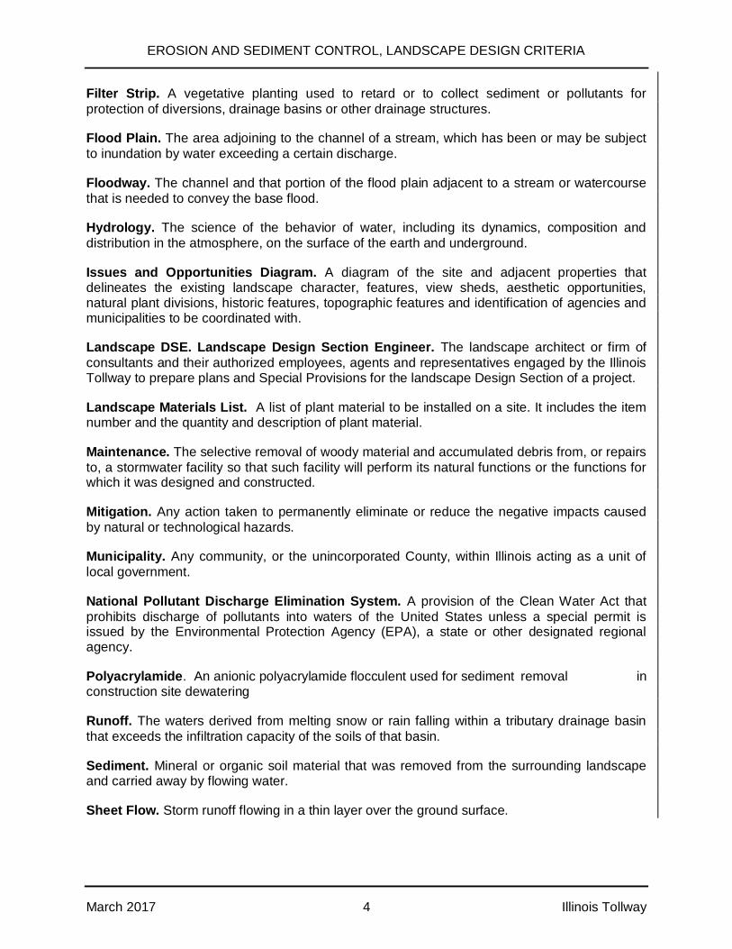
Filter Strip. A vegetative planting used to retard or to collect sediment or pollutants forprotection of diversions, drainage basins or other drainage structures.
Flood Plain. The area adjoining to the channel of a stream, which has been or may be subjectto inundation by water exceeding a certain discharge.
Floodway. The channel and that portion of the flood plain adjacent to a stream or watercoursethat is needed to convey the base flood.
Hydrology. The science of the behavior of water, including its dynamics, composition anddistribution in the atmosphere, on the surface of the earth and underground.
Issues and Opportunities Diagram. A diagram of the site and adjacent properties thatdelineates the existing landscape character, features, view sheds, aesthetic opportunities,natural plant divisions, historic features, topographic features and identification of agencies andmunicipalities to be coordinated with.
Landscape DSE. Landscape Design Section Engineer. The landscape architect or firm ofconsultants and their authorized employees, agents and representatives engaged by the IllinoisTollway to prepare plans and Special Provisions for the landscape Design Section of a project.
Landscape Materials List. A list of plant material to be installed on a site. It includes the itemnumber and the quantity and description of plant material.
Maintenance. The selective removal of woody material and accumulated debris from, or repairsto, a stormwater facility so that such facility will perform its natural functions or the functions forwhich it was designed and constructed.
Mitigation. Any action taken to permanently eliminate or reduce the negative impacts causedby natural or technological hazards.
Municipality. Any community, or the unincorporated County, within Illinois acting as a unit oflocal government.
National Pollutant Discharge Elimination System. A provision of the Clean Water Act thatprohibits discharge of pollutants into waters of the United States unless a special permit isissued by the Environmental Protection Agency (EPA), a state or other designated regionalagency.
Polyacrylamide. An anionic polyacrylamide flocculent used for sediment removal inconstruction site dewatering
Runoff. The waters derived from melting snow or rain falling within a tributary drainage basinthat exceeds the infiltration capacity of the soils of that basin.
Sediment. Mineral or organic soil material that was removed from the surrounding landscapeand carried away by flowing water.
Sheet Flow. Storm runoff flowing in a thin layer over the ground surface.
EROSION AND SEDIMENT CONTROL, LANDSCAPE DESIGN CRITERIA
March 2017 5 Illinois Tollway
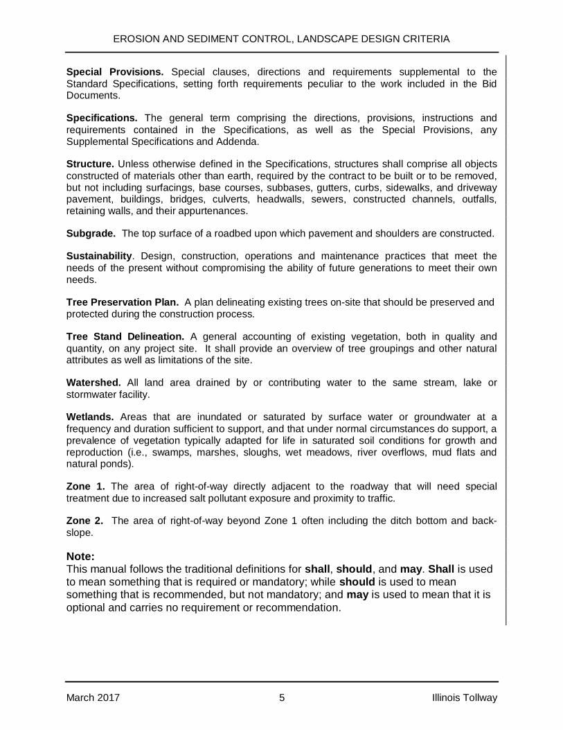
Special Provisions. Special clauses, directions and requirements supplemental to theStandard Specifications, setting forth requirements peculiar to the work included in the BidDocuments.
Specifications. The general term comprising the directions, provisions, instructions andrequirements contained in the Specifications, as well as the Special Provisions, anySupplemental Specifications and Addenda.
Structure. Unless otherwise defined in the Specifications, structures shall comprise all objectsconstructed of materials other than earth, required by the contract to be built or to be removed,but not including surfacings, base courses, subbases, gutters, curbs, sidewalks, and drivewaypavement, buildings, bridges, culverts, headwalls, sewers, constructed channels, outfalls,retaining walls, and their appurtenances.
Subgrade. The top surface of a roadbed upon which pavement and shoulders are constructed.
Sustainability. Design, construction, operations and maintenance practices that meet theneeds of the present without compromising the ability of future generations to meet their ownneeds.
Tree Preservation Plan. A plan delineating existing trees on-site that should be preserved andprotected during the construction process.
Tree Stand Delineation. A general accounting of existing vegetation, both in quality andquantity, on any project site. It shall provide an overview of tree groupings and other naturalattributes as well as limitations of the site.
Watershed. All land area drained by or contributing water to the same stream, lake orstormwater facility.
Wetlands. Areas that are inundated or saturated by surface water or groundwater at afrequency and duration sufficient to support, and that under normal circumstances do support, aprevalence of vegetation typically adapted for life in saturated soil conditions for growth andreproduction (i.e., swamps, marshes, sloughs, wet meadows, river overflows, mud flats andnatural ponds).
Zone 1. The area of right-of-way directly adjacent to the roadway that will need specialtreatment due to increased salt pollutant exposure and proximity to traffic.
Zone 2. The area of right-of-way beyond Zone 1 often including the ditch bottom and back-slope.
Note:This manual follows the traditional definitions for shall, should, and may. Shall is usedto mean something that is required or mandatory; while should is used to meansomething that is recommended, but not mandatory; and may is used to mean that it isoptional and carries no requirement or recommendation.

EROSION AND SEDIMENT CONTROL, LANDSCAPE DESIGN CRITERIA
March 2017 6 Illinois Tollway
THIS PAGE INTENTIONALLY LEFT BLANK

EROSION AND SEDIMENT CONTROL, LANDSCAPE DESIGN CRITERIA
March 2017 7 Illinois Tollway
SECTION 2.0 GENERAL INFORMATION
2.1 Primary Documents
The primary documents developed through use of the criteria in this manual are:
· Special Provision 111 – Erosion and Sediment Control Stormwater PollutionPrevention Plan (SWPPP) Narrative,
· Erosion and Sediment Control Plan (ESCP),and
· Permanent Landscape Plan (PLP).
The SWPPP defines and describes the Best Management Practices (BMPs) for erosion andsediment control, good housekeeping measures, liquid and solid waste handling, spillprevention, and spill control measures to be used on the project site. The SWPPP includes anarrative, the ESCP, maintenance of specific ESCP measures, and the PLP showingpermanent ground cover.
The ESCP defines how properties and surface water(s) located on and outside of the projectarea will be protected from erosion and sediment damage by the use of temporary controlmeasures.
The PLP defines how the properties and surface water/s located outside of the project area willbe permanently protected from erosion and sediment damage by the use of permanent groundcover and vegetation.
The temporary and permanent erosion control measures function best when proper operationand maintenance of these measures are based on implementing the following main elements:
· data collection and evaluation of the project vicinity to identify areas that aresusceptible to erosion;
· assessment of the project site and determination of landscape requirements;
· review of the regulatory requirements for erosion and sediment control andlandscape in the project area;
· planning and design for the most suitable and sustainable erosion and sedimentcontrol and landscape measures; and
· proper inspection, installation, and maintenance of the proposed erosion andsediment control and permanent landscape control measures coordinated with theconstruction schedule.
All Designer and CM personnel working on the preparation and implementation of the ESCPand PLP for a specific project shall be knowledgeable of the current Illinois Tollway designcriteria in roadway Erosion and Sediment Control and Landscape Design for highways.

EROSION AND SEDIMENT CONTROL, LANDSCAPE DESIGN CRITERIA
March 2017 8 Illinois Tollway
2.2 Projects Not Requiring Erosion and Sediment Control
Illinois Tollway projects which do not involve clearing and grubbing, excavation, stockpiling ofsoil and aggregate, borrow, or construction of embankment normally will not typically requiretemporary erosion and sediment control measures. Illinois Tollway projects which involve onlyisolated excavation areas of less than 1 acre combined total disturbed area will not normallyrequire an ESCP. The following are examples of routine construction and maintenanceoperations that normally will not require erosion and sediment control measures:
· installation of lighting, signing, traffic signals, or guardrail;
· weed spraying;
· pavement marking;
· seal coating;
· pavement patching;
· planting of woody landscaping materials; and
· pond outlet cleaning or ditch scraping if the soil is not redeposited on the site.
If a single project involves a cumulative land disturbance of 1 acre or more, such asrepair/replacement of guardrail at numerous locations, an ESCP plan and an NPDES permit isrequired.
Refer to Article 2.3 Policies and Regulations and the Illinois Tollway’s Special Provision 111Stormwater Pollution Prevention Plan.
2.3 Policies and Regulations
SWPPPs, including the development of ESCPs and control measures, are required on all IllinoisTollway projects that will expose areas of soil to potential displacement by precipitation events,wind, or other means, such that the sediment:
· could adversely affect traffic on the Illinois Tollway or associated ROW,
· could be conveyed into stormwater systems or receiving waters, i.e., natural streams
· could affect adjacent properties or sensitive environmental areas adjacent to theproject site.
The need for erosion and sediment control measures shall be evaluated in the early designstages, prior to the preparation of design plans, so that the identified needed measures can beaccounted for later in the ESCP and PLP design phases. The ESCPs shall provide pre-construction/during construction drawings that include information identifying the types oferosion and sediment control practices to be used, their locations, and when they shall beinstalled in relation to the sequence of construction operations that will expose soil. In somecases, the Designer may recommend specific sequences of construction in order to address theprotection of a sensitive area from erosion and sediment damage. Permanent landscape

EROSION AND SEDIMENT CONTROL, LANDSCAPE DESIGN CRITERIA
March 2017 9 Illinois Tollway
features, such as proposed trees and shrubs, should also be provided on the PLP postconstruction drawings when included in the scope of work.
The ESCP and/or PLP shall incorporate green infrastructure where appropriate and practicable.Stormwater management shall mimic natural processes whenever possible, such as directingstormwater to areas where infiltration, evapotranspiration, or water quality practices should beutilized. (Infiltration practices shall not be implemented in areas where vehicle fueling ormaintenance will occur, where there is shallow bedrock, areas with contaminated soil orgroundwater, or areas within 400 feet of a community drinking water supply or 200 feet of aprivate water supply well.) Natural buffers shall be provided or maintained around surfacewaters. Soil compaction should be minimized and topsoil preserved, unless infeasible.
The ESCPs and/or PLPs shall attempt to incorporate one or more of the following strategies, inorder of preference:
1. preservation of natural features of the site, including open space, naturalstormwater storage, and infiltration features
2. preservation of existing natural streams, channels, and drainage ways
3. minimization of new impervious surfaces or unnecessary soil compaction
4. conveyance of stormwater in open vegetated channels
Construction of structures that provide both water quality and water quantity control, withstructures serving multiple sites preferable to those serving individual sites.
The Designer shall collect and analyze the existing site conditions as described in Article 3.1Planning, Design Guidelines, and Submittal Requirements. A summary of submittalrequirements follows:
Design Concept Submittal includes:
· data collecting and inventory development including, but not limited to, an ExistingVegetative Assessment (EVA) and an Issues and Opportunities Diagram (IOD); and
· addressing the Environmental Studies Inventory Sheet and Erosion and SedimentControl Analysis Form in the Illinois Tollway’s Environmental Studies Manual.
Preliminary Design Submittal includes:
· developing the SWPPP;
· interpreting, evaluating, and applying data; and
· developing preliminary plans.
Pre-Final Design Submittal includes:
· development of ESCP and

EROSION AND SEDIMENT CONTROL, LANDSCAPE DESIGN CRITERIA
March 2017 10 Illinois Tollway
· development of PLP.
The following statutes, regulations, and references can be consulted to properly define theelements that shall be incorporated in the SWPPP, the ESCP, and the PLP.
2.3.1 Federal Statutes, Regulations and Policies
There are federal regulations overseen by numerous agencies. These agencies are the U.S.Environmental Protection Agency (EPA), USACE, the U.S. Department of Agriculture’s NaturalResources Conservation Service (NRCS), and the U.S. Fish and Wildlife Service.
Key regulations and policies written by these agencies include:
· National Environmental Policy Act
· Water Quality Act (Clean Water Act Amendments) (1987)
· Clean Water Act: Sections 309, 319, 401, 402, 404
· EPA – Office of Water: “Controlling Nonpoint Source Runoff Pollution from Roads,Highways and Bridges” (EPA-841-F-95-008a / 1995)
· United States Code Title 23: Highways - Section 319: Landscaping and ScenicEnhancement
· 23 CFR 650, Subpart B Erosion and Sediment Control on Highway ConstructionProjects
· 23 CFR 752: Landscape and Roadside Development
· 40 CFR 450: Effluent Limitation Guidelines and Standards for the Construction andDevelopment Point Source Category
2.3.2 Illinois Statutes and Directives
A number of Illinois statutes and directives contain guidance for landscaping, erosion andsediment control measures, not limited to the following:
· 615 ILCS 5 Rivers, Lakes, and Streams Act
· 35 Illinois Adm. Code, Subtitle C, Chapter I
2.3.3 Guidance Documents
Several guidance documents are available to assist in planning, design, and implementation ofthe landscaping and erosion and sediment control measures for the Illinois Tollway projects (alldocuments shall be the latest revision or edition), including:
· AASHTO – Guide for Transportation Landscape and Environmental Design
EROSION AND SEDIMENT CONTROL, LANDSCAPE DESIGN CRITERIA
March 2017 11 Illinois Tollway
· AASHTO – A Guide for Achieving Flexibility in Highway Design
· AASHTO – Roadside Design Guide
· Environmental Protection Agency (EPA) – Developing Your Stormwater PollutionPrevention Plan; A Guide for Construction Sites
· Illinois Tollway – Design Section Engineers Manual
· Illinois Tollway – Drainage Design Manual
· Illinois Tollway – Environmental Studies Manual
· Illinois Tollway – Design Guidelines (Architecture, Landscape, Signage, etc.)
· Illinois Tollway – Standard K Drawings and Section M Base Sheets
· Illinois Tollway – Supplemental Specifications to the Illinois Department ofTransportation (IDOT) Standard Specifications for Road and Bridge Construction
· Illinois Tollway – Criteria for Removal and Replacement of Trees
· Illinois Tollway – Roadside Mowing Policy
· IDOT – Bureau of Design and Environmental Manual, Chapter 41 – Construction SiteStorm Water Pollution Control
· IDOT – Bureau of Design and Environmental Manual, Chapter 59 – LandscapeDesign
· IDOT – Standard Specifications for Road and Bridge Construction
· IEPA/NRCS/SWCD – Illinois Urban Manual
As manuals are updated and re-issued, please ensure that the most recent version of thedocument is being used for guidance.
If there is any conflict between this Erosion and Sediment Control, Landscape Design Criteriaand any reference document or specification, the Designer shall discuss this conflict with theIllinois Tollway Project Manager (PM) before proceeding.
2.4 Coordination and Documentation
2.4.1 Coordination
Below is a discussion of coordination activities needed during the preparation of the soil erosioncontrol and landscape plans.
A. Coordination of several disciplines (e.g., engineering, landscape architecture,biology, hydrology, and others) is needed during the project’s design in order to meet
EROSION AND SEDIMENT CONTROL, LANDSCAPE DESIGN CRITERIA
March 2017 12 Illinois Tollway
the proper environmental requirements. This is necessary not only for large andcomplex projects but also for small and simple projects. The Designer shall obtain allavailable inputs to ensure a coordinated, environmentally-based, integrative designapproach.
B. Coordination with other state and federal regulatory agencies is necessary wheretransportation projects involve wetlands, endangered species, Illinois natural areas,nature preserves, historic sites, naturally or culturally sensitive areas, or where theplanned facility is adjacent to public natural resources such as streams, forests, orforest preserves. The design aspect of these projects shall be identified by theDesigner and coordinated by the assigned Illinois Tollway PM/Coordinator.
C. The Designer shall support the Illinois Tollway PM/Coordinator when coordination isneeded with local jurisdictional agencies or property/landowners adjacent to oraffected by Illinois Tollway projects. Coordination at the local level includes counties,municipalities, schools, park and forest preserve districts, chambers of commerce,residential and commercial developments, and other special districts. Coordination atthe general public level should include groups that could have valuable input to theproject or have special requirements.
D. The NPDES General Construction Permit to regulate the discharge of stormwaterfrom a construction site, which is granted to the Illinois Tollway, requires certainitems be prepared and kept current by the CM. See Special Provisions 111.1 and111.2 and Part IV of the NPDES General Construction Permit for more detailsregarding the requirements for developing the NPDES SWPPP. Appendix 1 providesa summary of the various NPDES forms that may be applicable to a project.
2.4.2 Documentation
The Illinois Tollway’s Environmental Studies Manual provides guidance on the necessarycoordination and documentation for different types of projects.
Preparation of the documentation for ESCPs and/or PLPs involves the following steps.
A. Collection of data, including:
· topography,
· rainfall frequency and intensities,
· drainage pattern (overland watersheds and existing drainage systems),
· soil data and ground cover,
· adjacent area’s conditions and land use,
· U.S. Geologic Survey Hydrologic Maps/hydraulic characteristics,
· wetlands and environmentally sensitive areas,
EROSION AND SEDIMENT CONTROL, LANDSCAPE DESIGN CRITERIA
March 2017 13 Illinois Tollway
· flood elevations,
· vegetation surveys and requirements, and
· preparation of the Erosion and Sedimentation Control Analysis checklist.
B. Analysis of the data, including:
· drainage areas, including areas where sheet or concentrated flows enter or leaveIllinois Tollway property,
· vegetation,
· runoff calculation/s and runoff coefficient/s for the SWPPP
· detention requirements, hydrology, ground water elevations, and
· evaluation of the soil erodibility potential, hydrology, and topography.
C. Development of project site plan, including the proposed drainage facilities.
D. Development of erosion and sediment control and landscape plans, including:
· applicable Section 4.0 requirements for PLP;
· narrative for ESCP, permit submittals, and/or ESIS;
· overview drawings, detailed plans, and staging sequence narrative;
· construction details; and
· supporting calculations.
2.4.3 Request for Design Deviation
If the landscape or erosion control design submitted by the Designer deviates from the criteriaspecified in this manual, the Designer shall prepare and submit a Design Deviation to the IllinoisTollway in accordance with Article 10.1.5 of the DSE Manual.
The Designer shall prepare documentation to be used to obtain local permits/approval if localagency requirements for landscaping or erosion and sediment control are more stringent thanthe Illinois Tollway’s requirements; these requirements shall be considered in the developmentof the ESCP and the PLP. If the proposed ESCP or the PLP does not meet or exceed the localordinances, the Designer shall summarize for the Illinois Tollway information and considerationfor the differences and explain why the more stringent requirements cannot be met.
The Illinois Tollway will review the information submitted and direct the Designer on a course ofaction to continue development of contract documents and permit applications.
EROSION AND SEDIMENT CONTROL, LANDSCAPE DESIGN CRITERIA
March 2017 14 Illinois Tollway
THIS PAGE INTENTIONALLY LEFT BLANK
EROSION AND SEDIMENT CONTROL, LANDSCAPE DESIGN CRITERIA
March 2017 15 Illinois Tollway
SECTION 3.0 EROSION AND SEDIMENT CONTROL
3.1 Planning, Design Guidelines, and Submittal Requirements
3.1.1 Planning
An effective ESCP shall minimize the amount of sediment displacement and erosion due toconstruction activities. The success of the ESCP depends mainly on site planning, coordination,maintenance, and operation. The following outlines the main principles of planning a successfulECSP.
A. The Designer shall coordinate with all disciplines to understand construction stagingand drainage patterns tributary to and within the project limits. The Designer shallobtain delineations of drainage divides, tributary areas, and drainage flow routesfrom drainage reports (if available).
B. The Designer shall understand the erosion potential of existing soils, includingclassifications, slopes, stream corridors, and special management areas.
C. The Designer shall identify potential problem areas which will likely require theimplementation of erosion and sediment control measures and identify potentialsolutions. Consideration should include, but not be limited to, adjacent property use,distance and sensitivity of receiving waters, receiving waters with impaired water ortotal maximum daily loads (TMDLs), watershed plans developed for constituentsassociated with roadways or construction, adjacent high quality naturalresources/ADID wetlands, the use of rubbilized concrete for road base, etc.
D. The Designer shall identify affected agencies that will require coordination meetings.The Designer shall prepare a listing of issues that will need to be discussed at themeeting and be prepared to present solutions to identified issues.
E. The Designer shall plan the use of appropriate erosion and sediment controlmeasures. The Contractor may recommend changes in the ESCP, as appropriate.The CM will accept or reject Contractor suggestions and advise Contractor of same.The CM is responsible for erosion and sediment control oversight to ensure propermeasures are installed, effective, and maintained throughout all phases ofconstruction, including shutdown periods.
F. Throughout all phases of design, the Designer shall implement a thorough reviewprocess involving both design and construction personnel. The Designer shallinclude a review program of the plans and specifications to assure that localconcerns are addressed and regulatory requirements are met, including a plan fortemporary stormwater storage during construction.
G. The Designer shall prepare the Erosion and Sediment Control Analysis checklist.
Illinois Tollway Supplemental Specifications Section 280, Special Provision 111-Erosion andSediment Control, Standard K1 Drawings, and Section M Base Sheets are available to theDesigner. The most current versions shall be obtained from the Illinois Tollway’s website. The

EROSION AND SEDIMENT CONTROL, LANDSCAPE DESIGN CRITERIA
March 2017 16 Illinois Tollway
information is to be used to identify the erosion and sediment control items and quantities to beincluded in the contract documents.
For further guidance see Appendix 2 for the EPA’s Stormwater Phase II Final Rule, SmallConstruction Program Overview.
3.1.2 Design Guidelines
The Designer shall use the design guidelines provided to develop erosion and sediment controlsolutions for individual site conditions. Consideration shall be given to erosion and sedimentcontrol early on in the design process to properly account for it in the design process. Theseguidelines are included to provide the Designer with a general sense of the important factorsthat need to be accounted for throughout the design. The design guidelines are listed below bycategory:
A. General Design
1. Plan the construction to take advantage of existing topography, soils, drainagepatterns, and natural vegetation.
2. Apply erosion control practices prior to construction to reduce on-site erosion andprevent off-site sediment damage.
3. Complete coordination meetings with affected agencies early on in the designprocess to solicit input and comments to be incorporated in the ESCP.
4. If the Designer determines that there is a need for additional measures notcovered under Illinois Tollway guidelines, the Designer can use one of thedrawings included in the Illinois Urban Manual or design details from IDOT’sBureau of Design and Environmental Manual, Chapter 41. The Designer shouldalso provide a custom design based upon site specific requirements. TheDesigner shall submit the drawings to Illinois Tollway for review and acceptance.
5. Design erosion control features to facilitate timely maintenance, repair, andreplacement of impaired measures.
6. The erosion of new embankment slopes is to be reduced by construction oftemporary berms with temporary pipe slope drains at the end of eachconstruction day. The size and distance between pipes are to be designed by theDesigner in accordance with the Illinois Urban Manual or Illinois TollwayStandard Drawings. Calculations supporting non-standard spacing shall besubmitted for review.
7. The Illinois Tollway has initiated a program that utilizes recycled concrete forroadway rehabilitation projects. Excavated concrete is broken up and crushedinto smaller pieces, often in situ, to create an aggregate base for new pavement.The use of recycled or rubblized concrete creates unique challenges for erosionand sediment control design. The Designer shall be mindful of the fine materialthat is washed away during storm events, often continuing beyond thecompletion of construction. In addition, the presence of limestone in the rubblizedconcrete can significantly alter the pH of the stormwater runoff. Where

EROSION AND SEDIMENT CONTROL, LANDSCAPE DESIGN CRITERIA
March 2017 17 Illinois Tollway
rubblization is to be utilized, the Designer shall investigate the current technologyand identify locations and design devices that will allow for the remediation ofrubblized concrete fines prior to discharging stormwater to outside of the ROW.In many instances, the material can be removed via vegetated ditches as long asthere is sufficient time and space for removal prior to the discharge of thestormwater to outside the ROW or to receiving waters.
If stormwater will discharge to sensitive ecological systems, such as creeks orwetlands, or interfere with the growth of adjacent plants and grasses, methodsfor neutralizing the pH shall also be assessed. In no instance shall liveplants/plugs be installed near underdrain outfalls. The Designer shall identifymethods for preventing impacts to stormwater discharging to outside the IllinoisTollway ROW from rubblized concrete, and provide plans to the Illinois Tollwayfor review and acceptance. Contract documents shall incorporate appropriateBMPs into project plans to prevent these types of sediments from leaving IllinoisTollway ROW.
The Illinois Tollway Drainage Design Manual (Illinois Tollway DDM) hasadditional requirements for subsurface drainage design in areas constructed withrubblized concrete See Article 10.7.2 of the Illinois Tollway DDM for additionalinformation.
B. Basic Principles
Overview
Construction activities involving earthwork (e.g., clearing and grubbing, grading,importing fill material, utility installation) disturb the soil such that when the vegetation isremoved, the soil becomes exposed and vulnerable to excessive erosion. This results insediment being the most common pollutant associated with construction activities.Sediment can be detrimental to aquatic life by interfering with photosynthesis,respiration, growth, reproduction, and oxygen exchange in waterways. In addition,sediment particles can transport other pollutants that are attached to them, includingnutrients, trace metals, and hydrocarbons. Sediment particles (e.g., silts and clays) arethe primary components of total suspended solids, a common water quality parameter.
Construction activities involving building materials, vehicular use, and landscaping havethe potential to contribute pollutants to stormwater. Common pollutants related to theseconstruction activities include vehicle fluids, curing compounds, solvents, paints,emulsions, oil and grease, metals, organics, pesticides, nutrients, trash, debris, andfloatables, as well as other miscellaneous waste.
Erosion and Sedimentation
Erosion is the process of soil particle detachment from the land surface by the forces ofwind, water, or gravity. After the soil particles have been detached (eroded), thesuspended soil particles in transport are referred to as sediment. Sedimentation occurswhere suspended sediment settles out and is deposited. Note that gravels and sandstend to drop out of suspension more rapidly than finer particles (e.g., silts and clays) dueto differences in size, density, and shape.
EROSION AND SEDIMENT CONTROL, LANDSCAPE DESIGN CRITERIA
March 2017 18 Illinois Tollway
Where soil is cleared or disturbed, erosion occurs at a much higher rate due to directexposure to erosive forces (e.g., raindrop impacts, sheet erosion, rill erosion). Landclearing disturbances can also alter the natural structure of soil and weaken thereinforcing matrix of plant roots and organic compounds. The EPA estimates thatunprotected construction sites can experience erosion at over 100 times the natural rate.As a result, primary emphasis should be placed on erosion control practices as they arepreventative source controls, while sediment control practices are secondary measuresdesigned to contain sediment after it is in transport, preventing it from leaving the site.Sediment control is often more expensive than erosion control.
Types of Erosion
1. Erosion from Raindrop Impact. The dislodgement of soil particles by fallingraindrops is a primary agent of erosion, particularly on soils with sparsevegetative cover. Individual soil particles can be splashed over 1.5 feet in heightand 5 feet to the side.
2. Sheet Erosion. Splashed soil particles are moved in a semi-suspended layeruniformly over the land surface. The distance of sheet flow depends on slope,soil roughness, type of vegetative cover, and rainfall intensity.
3. Rill and Gully Erosion. As runoff concentrates, tiny channels form called rills. Rillerosion is the form that produces the greatest amount of soil loss worldwide. Rillsare channels small enough to be smoothed by normal tillage. As the runoffaccumulates in the rills, they erode further, causing gullies to form. Gullies are solarge that they cannot be smoothed by normal tillage. The rate of rill erosion caneasily be 100 times greater than that of sheet flow, and the rate of gully erosioncan easily be 100 times greater than rill erosion. Due to the significant amount ofsediment generated by rill and gully erosion, these types of erosion shall begiven top priority for elimination, reduction, and control.
4. Ditch and channel erosion is produced by a concentrated flow moving within aditch or channel without energy dissipation such as the access to a floodplain.This type of erosion can undermine channel banks and erode ditch/channelbottoms. Depending on the channel capacity, this form of erosion can do severedamage to a drainage system.
The following basic variables are to be considered during the preparation of the ESCP.
1. The soil erosion hazard varies with soil type, soil surface conditions, the slope ofthe lands (S), and the length of the slope exposed to the stormwater runoff (L).General guidelines are as follows:
Low Erosion Hazard: for S = < 4% and L > 300 feet
Moderate Erosion Hazard: for S = 4 to 7% and L > 150 feet
High Erosions Hazard: for S = > 7%

EROSION AND SEDIMENT CONTROL, LANDSCAPE DESIGN CRITERIA
March 2017 19 Illinois Tollway
The higher the erosion hazard, the more critical the design, practice, installation,and maintenance of the erosion and sediment control measures. Table 1 belowdemonstrates this principle.
Table 1:Influence of Environmental Conditions on Erosion*
*Table above used with permission, courtesy of the Kentucky Division of Water’s Kentucky Best Management Practices (BMPs) forControlling Erosion, Sediment, and Pollutant Runoff from Construction Sites Planning and Technical Specifications Manual ,(undated), Tetra Tech, Inc.
2. Locate and identify any wetlands or special management areas for protection.
3. Determine if rubblized or recycled concrete will be used. If so, identify locationswhere Illinois Tollway stormwater leaves the ROW and affects stormwater qualityand/or plantings.
4. Evaluation for control of erosion shall include the changes in drainage patternsfor various construction phases, time of year, and site conditions.
5. Divert off-site runoff flowing through the site away from disturbed areas.
6. Use construction phases and clearing limits to maintain the natural vegetation foras long as possible on the site.
7. Attempt to prevent erosion, and trap sediments from unavoidable erosion.

EROSION AND SEDIMENT CONTROL, LANDSCAPE DESIGN CRITERIA
March 2017 20 Illinois Tollway
8. Stabilize and protect disturbed areas as soon as possible. Retain any releasedsediment within the construction area and reduce tracking off-site.
9. Reflect in the construction plans and specifications that permanent erosion andsediment control measures will be implemented as quickly as practical.
10. Develop a thorough monitoring/inspection, maintenance, and follow-up program.
C. Drainage and Runoff Control
1. Understand existing drainage patterns within the project limits and offsite flowstributary to the project area.
2. When possible, keep off-site runoff from entering the construction site throughthe use of diversion ditches and channels.
3. Keep runoff velocities low and retain sediment loaded runoff on the constructionsite.
4. Temporary ditch checks or rock check dams shall be used in all proposed ortemporary ditches to reduce velocity and to prevent excessive erosion in a ditchor swale. These devices are not to be used as a substitute for sediment trappingdevices, such as sediment traps or basins. Spacing between devices shall bedetermined from Figure 1, Ditch Check Spacing (next page).
5. Super silt fence should be considered when slope angle and/or the contributingslope results in concentrated flows, and/or the design life of the silt fence isgreater than 6 months.
6. Neither silt fence nor super silt fence barriers are designed for drainage channelswhere concentrated flows will occur, such as ditches, channels, or streams. Thefences may be undercut and damaged by the impact of concentrated channelflow.

EROSION AND SEDIMENT CONTROL, LANDSCAPE DESIGN CRITERIA
March 2017 21 Illinois Tollway
FIGURE 1 – DITCH CHECK SPACING
% SLOPE HEIGHT AT CENTER/OVERFLOW POINTOF DITCH CHECK
SPACING OF DITCHCHECK IN
FEET8% 1.0’ 13’
1.5’ 20’2.0’ 26’
7% 1.0’ 14’1.5’ 21’2.0’ 28’
6% 1.0’ 17’1.5’ 26’2.0’ 34’
5% 1.0’ 20’1.5’ 30’2.0’ 40’
4% 1.0’ 25’1.5’ 38’2.0’ 50’
3% 1.0’ 33’1.5’ 50’2.0’ 66’
2% 1.0’ 50’1.5’ 75’2.0’ 100’
1% & BELOW 1.0’ 100’1.5’ 150’2.0’ 200’
1. Chart indicates recommended spacing of ditch checks, based upon the percentof slope.
2. For applications not addressed in this figure, spacing shall be equal to the heightof the ditch check divided by the slope. This ensures that the base of theupstream check is at the same elevation as the crest of the downstream check.
3. The spacings indicated in this figure are for guidance only. The Designer shalltake into consideration all variables in the design and selection of the type ofditch checks used, including but not limited to soil types, surface water flow, andother construction activities unique to the individual project which may impacterosion and sediment control structures.
4. Adapted from the Illinois Urban Manual.
EROSION AND SEDIMENT CONTROL, LANDSCAPE DESIGN CRITERIA
March 2017 22 Illinois Tollway
D. Soils, Excavation, and Disturbed Areas
1. Understand soil conditions within the project limits.
2. Minimize the extent of area exposed at any one time, and the duration of theexposure.
3. Use perimeter control practices to protect disturbed areas from off-site runoff andprevent sedimentation damage to areas located downstream of the disturbedareas.
4. Disturbed areas are to be protected from erosion in a timely manner and erosionstabilization measures shall be initiated as soon as practicable in all portions ofthe site.
For portions of the site where construction activities have temporarily ceased andwill not resume within 14 days (e.g., the total time period that construction activityis temporarily ceased will be 14 days or more), stabilization measures shall beinitiated within 1 working day from the time activities have ceased. In portions ofthe site where construction activities have permanently ended, erosionstabilization measures shall immediately take place and final erosion measuresused whenever possible.
Any adjacent sediment control measures shall continuously remain in place whileconstruction has temporarily or permanently ended and until final erosionstabilization is complete.
Same day stabilization is to be implemented as outlined in the Illinois TollwaySupplemental Specification Article 280.15(c). Same day stabilization is typicallyused to minimize erosion and the movement of soils at those areas shown on theplans, as directed by the CM, or where construction activity will temporarily ceasefor 14 days. The primary method to perform same day stabilization is through theuse of Temporary Stabilization with straw mulch, with permanent measuresinstalled at the earliest opportunity. This item generally provides for the additionallabor that may be required to perform the continuous soil stabilization workneeded to reduce sediment loss where limited space is available for sedimentcontrol measures.
E. Construction Practices and Issues
1. All temporary diversions, swales, ditches, etc. shall be installed in a manner thatprotects these areas from erosion during construction.
2. Apply and maintain the appropriate erosion and sediment control measures onthe project site during all phases of construction, including construction shutdown periods.
EROSION AND SEDIMENT CONTROL, LANDSCAPE DESIGN CRITERIA
March 2017 23 Illinois Tollway
Where the initiation of stabilization measures is precluded by snow cover,stabilization measures shall be initiated as soon as practicable.
3. Clearly define wherever dewatering is expected to be needed, pointing out theneed to pass the sediment laden water through a sediment trapping device priorto leaving the construction site.
4. Any silt fence constructed in an area where ponding depth may exceed 18” shallbe constructed as a super silt fence.
5. Super silt fence shall be used when the contributing slope is longer than 100’, theslope is greater than 3%, and/or the design life of the silt fence is greater than 6months. This item should also be used to protect wetlands and otherenvironmentally sensitive areas.
6. Neither silt fence nor super silt fence barriers are designed for drainage channelswhere concentrated flows will occur, such as ditches, channels, or streams. Thefences may be undercut and damaged by the impact of concentrated channelflow.
7. Clearly define ways that the Contractor can ensure all sediment laden wateroriginating on the site will flow through sediment control devices prior to leavingthe site.
8. Upon completion of construction and/or permanent stabilization, temporaryerosion and sediment control measures shall be removed. Temporary erosioncontrol measures may be left in place for a period of time following construction ifconstruction included rubblized/recycled concrete. Under these circumstances,temporary erosion and sediment control measures shall be left in place until finesfrom the rubblized/recycled concrete are no longer being washed out from theunderpavement. Temporary erosion and sediment control measures cannot beleft in place on a permanent basis, however, unless consistent with standardsfrom the Illinois Tollway DDM. In no instance may riprap or ditch checks be left inplace unless the CM gets written acceptance from the Illinois TollwayEnvironmental Unit and it does not pose a hazard to the motorist.
Refer to the Illinois Tollway’s Standard K1 and Section M Base Sheet Drawings forinformation regarding various erosion and sediment control measures and theapplications to which each of them is best suited for Illinois Tollway projects. For furtherguidance see the EPA’s Developing Your Stormwater Pollution Prevention Plan, AGuide for Construction Sites.
3.1.3 Design Concept Submittal
The design concept shall be developed in conjunction with the overall design team, following theguidelines provided. The primary focus of this submittal will be to understand the existingconditions, plan the overall erosion and sediment control concept, and define the permitrequirements. Coordination with all project disciplines including Landscape Architect, DrainageEngineer, Environmental Planner, and governmental and regulatory agencies will be criticalduring this phase of the project. The Designer shall identify any special requirements that need
EROSION AND SEDIMENT CONTROL, LANDSCAPE DESIGN CRITERIA
March 2017 24 Illinois Tollway
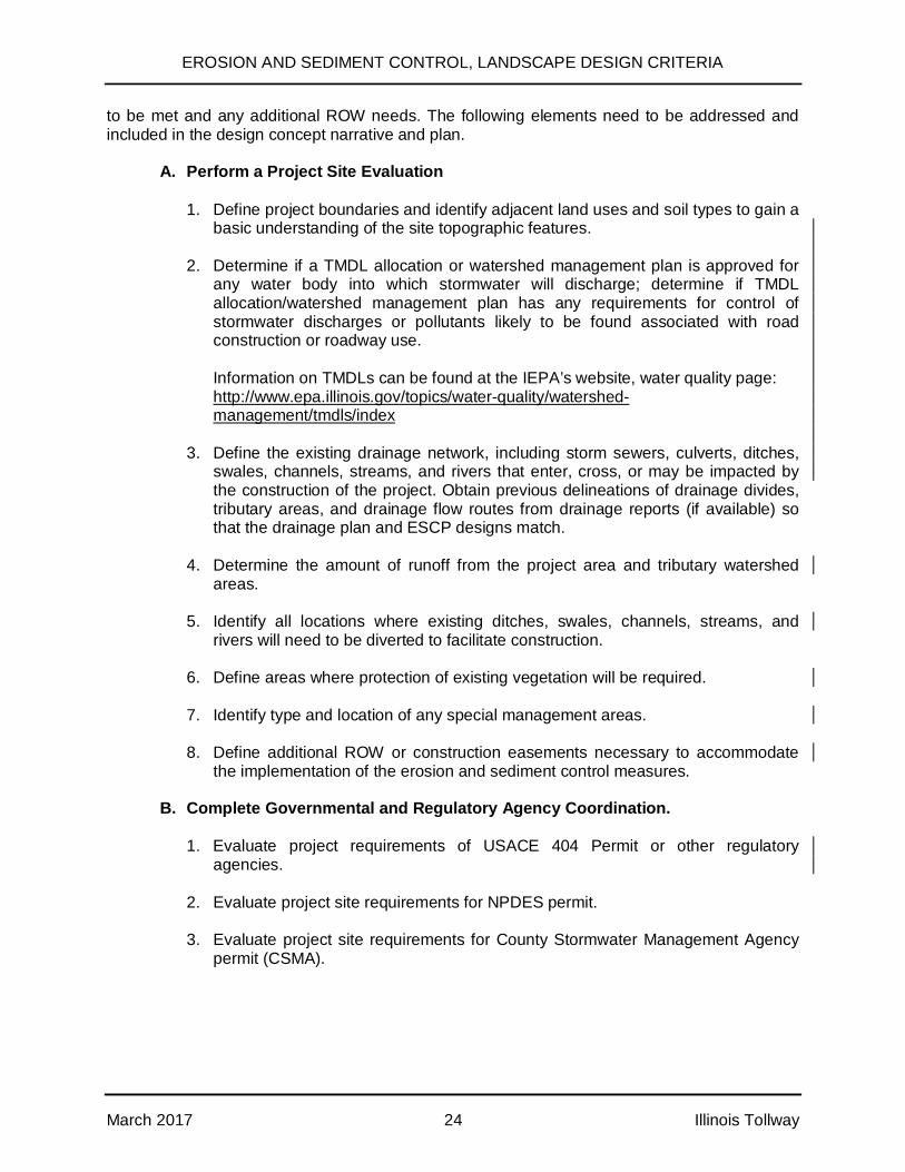
to be met and any additional ROW needs. The following elements need to be addressed andincluded in the design concept narrative and plan.
A. Perform a Project Site Evaluation
1. Define project boundaries and identify adjacent land uses and soil types to gain abasic understanding of the site topographic features.
2. Determine if a TMDL allocation or watershed management plan is approved forany water body into which stormwater will discharge; determine if TMDLallocation/watershed management plan has any requirements for control ofstormwater discharges or pollutants likely to be found associated with roadconstruction or roadway use.
Information on TMDLs can be found at the IEPA’s website, water quality page: http://www.epa.illinois.gov/topics/water-quality/watershed-
management/tmdls/index
3. Define the existing drainage network, including storm sewers, culverts, ditches,swales, channels, streams, and rivers that enter, cross, or may be impacted bythe construction of the project. Obtain previous delineations of drainage divides,tributary areas, and drainage flow routes from drainage reports (if available) sothat the drainage plan and ESCP designs match.
4. Determine the amount of runoff from the project area and tributary watershedareas.
5. Identify all locations where existing ditches, swales, channels, streams, andrivers will need to be diverted to facilitate construction.
6. Define areas where protection of existing vegetation will be required.
7. Identify type and location of any special management areas.
8. Define additional ROW or construction easements necessary to accommodatethe implementation of the erosion and sediment control measures.
B. Complete Governmental and Regulatory Agency Coordination.
1. Evaluate project requirements of USACE 404 Permit or other regulatoryagencies.
2. Evaluate project site requirements for NPDES permit.
3. Evaluate project site requirements for County Stormwater Management Agencypermit (CSMA).
EROSION AND SEDIMENT CONTROL, LANDSCAPE DESIGN CRITERIA
March 2017 25 Illinois Tollway
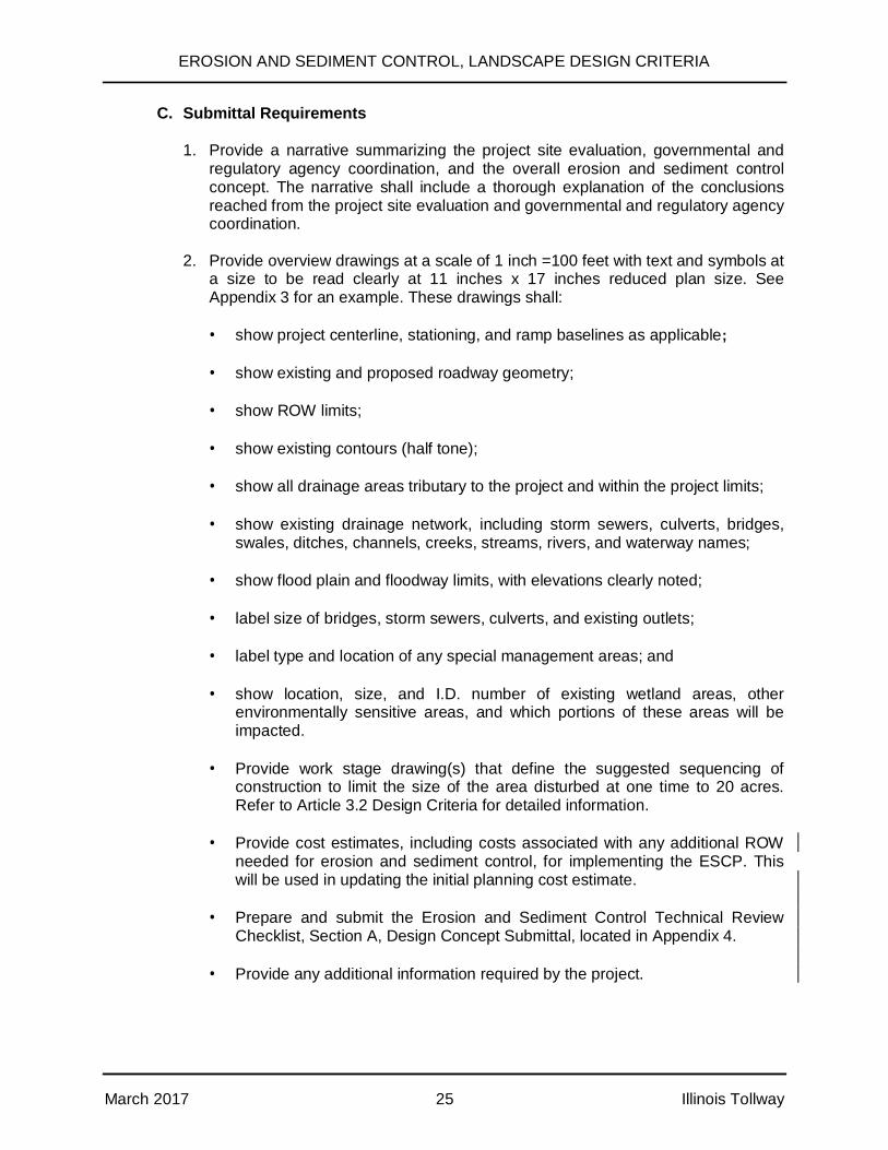
C. Submittal Requirements
1. Provide a narrative summarizing the project site evaluation, governmental andregulatory agency coordination, and the overall erosion and sediment controlconcept. The narrative shall include a thorough explanation of the conclusionsreached from the project site evaluation and governmental and regulatory agencycoordination.
2. Provide overview drawings at a scale of 1 inch =100 feet with text and symbols ata size to be read clearly at 11 inches x 17 inches reduced plan size. SeeAppendix 3 for an example. These drawings shall:
· show project centerline, stationing, and ramp baselines as applicable;
· show existing and proposed roadway geometry;
· show ROW limits;
· show existing contours (half tone);
· show all drainage areas tributary to the project and within the project limits;
· show existing drainage network, including storm sewers, culverts, bridges,swales, ditches, channels, creeks, streams, rivers, and waterway names;
· show flood plain and floodway limits, with elevations clearly noted;
· label size of bridges, storm sewers, culverts, and existing outlets;
· label type and location of any special management areas; and
· show location, size, and I.D. number of existing wetland areas, otherenvironmentally sensitive areas, and which portions of these areas will beimpacted.
· Provide work stage drawing(s) that define the suggested sequencing ofconstruction to limit the size of the area disturbed at one time to 20 acres.Refer to Article 3.2 Design Criteria for detailed information.
· Provide cost estimates, including costs associated with any additional ROWneeded for erosion and sediment control, for implementing the ESCP. Thiswill be used in updating the initial planning cost estimate.
· Prepare and submit the Erosion and Sediment Control Technical ReviewChecklist, Section A, Design Concept Submittal, located in Appendix 4.
· Provide any additional information required by the project.
EROSION AND SEDIMENT CONTROL, LANDSCAPE DESIGN CRITERIA
March 2017 26 Illinois Tollway
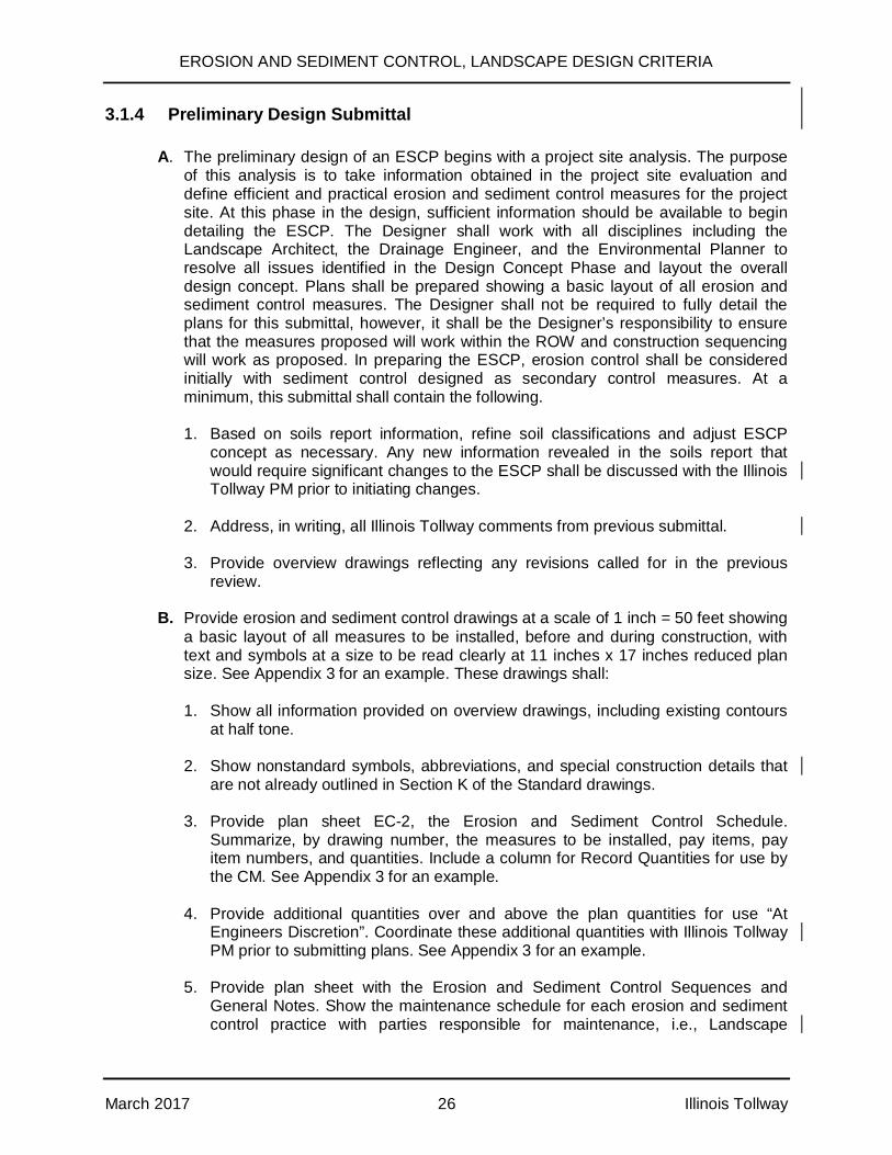
3.1.4 Preliminary Design Submittal
A. The preliminary design of an ESCP begins with a project site analysis. The purposeof this analysis is to take information obtained in the project site evaluation anddefine efficient and practical erosion and sediment control measures for the projectsite. At this phase in the design, sufficient information should be available to begindetailing the ESCP. The Designer shall work with all disciplines including theLandscape Architect, the Drainage Engineer, and the Environmental Planner toresolve all issues identified in the Design Concept Phase and layout the overalldesign concept. Plans shall be prepared showing a basic layout of all erosion andsediment control measures. The Designer shall not be required to fully detail theplans for this submittal, however, it shall be the Designer’s responsibility to ensurethat the measures proposed will work within the ROW and construction sequencingwill work as proposed. In preparing the ESCP, erosion control shall be consideredinitially with sediment control designed as secondary control measures. At aminimum, this submittal shall contain the following.
1. Based on soils report information, refine soil classifications and adjust ESCPconcept as necessary. Any new information revealed in the soils report thatwould require significant changes to the ESCP shall be discussed with the IllinoisTollway PM prior to initiating changes.
2. Address, in writing, all Illinois Tollway comments from previous submittal.
3. Provide overview drawings reflecting any revisions called for in the previousreview.
B. Provide erosion and sediment control drawings at a scale of 1 inch = 50 feet showinga basic layout of all measures to be installed, before and during construction, withtext and symbols at a size to be read clearly at 11 inches x 17 inches reduced plansize. See Appendix 3 for an example. These drawings shall:
1. Show all information provided on overview drawings, including existing contoursat half tone.
2. Show nonstandard symbols, abbreviations, and special construction details thatare not already outlined in Section K of the Standard drawings.
3. Provide plan sheet EC-2, the Erosion and Sediment Control Schedule.Summarize, by drawing number, the measures to be installed, pay items, payitem numbers, and quantities. Include a column for Record Quantities for use bythe CM. See Appendix 3 for an example.
4. Provide additional quantities over and above the plan quantities for use “AtEngineers Discretion”. Coordinate these additional quantities with Illinois TollwayPM prior to submitting plans. See Appendix 3 for an example.
5. Provide plan sheet with the Erosion and Sediment Control Sequences andGeneral Notes. Show the maintenance schedule for each erosion and sedimentcontrol practice with parties responsible for maintenance, i.e., Landscape

EROSION AND SEDIMENT CONTROL, LANDSCAPE DESIGN CRITERIA
March 2017 27 Illinois Tollway
Contractor and/or General Contractor. Show construction sequences forinstalling control measures in relation to specific stages of construction and earthdisturbance activities. Include the following general notes and details applicableto the project:
a. For erosion and sediment control general notes see Standard K1 and SectionM Base Sheet Drawings.
b. The permanent vegetation plan shall be used on all disturbed areaswhenever possible. A quantity for temporary stabilization with straw mulchshall also be provided for all anticipated disturbed areas.
c. Same day stabilization is to be implemented as outlined in the Illinois TollwaySupplemental Specification Articles 280.15(c). Same day stabilization istypically used to minimize erosion and the movement of soils at those areasshown on the plans or directed by the CM. Same day stabilization is typicallyperformed each day any soil disturbance occurs as a result of Contractor’soperations. The primary method to perform same day stabilization is throughthe use of Temporary Stabilization with straw mulch with permanentmeasures installed at the earliest opportunity. This item generally provides forthe additional labor that may be required to perform the continuous soilstabilization work needed to reduce sediment loss where limited space isavailable for sediment control measures.
d. Temporary sediment basin #____ and temporary sediment traps #____ and#____.
e. Stabilized construction entrances at Contractor’s access to work areas. Seestandard drawings K and Illinois Tollway – Supplemental Specification Article280.07 and Appendix 5 for additional direction.
f. Identify the vehicle washout areas.
6. Delineate disturbed area and provide drainage patterns for proposed conditions.Make special note of drainage areas used to size the perimeter controls,sediment traps, or retention basins.
7. Show the direction runoff flows prior to construction, during construction, andafter construction is completed. This may require duplicate drawings in somesituations.
8. Identify reaches that will require the use of staged construction, with temporary orpermanent stabilization of slopes, before additional excavation or placement offill. Label how many stages/phases of construction will be needed, with the slopelength (50 feet) and/or 15 feet fill or cut limitations shown on the Illinois TollwayStandard Drawing Section K1, at representative (20 acre) locations along theroute.
9. Show borrow sites and topsoil stockpile locations with erosion and sedimentcontrol measures around the perimeter of the stockpiles.
EROSION AND SEDIMENT CONTROL, LANDSCAPE DESIGN CRITERIA
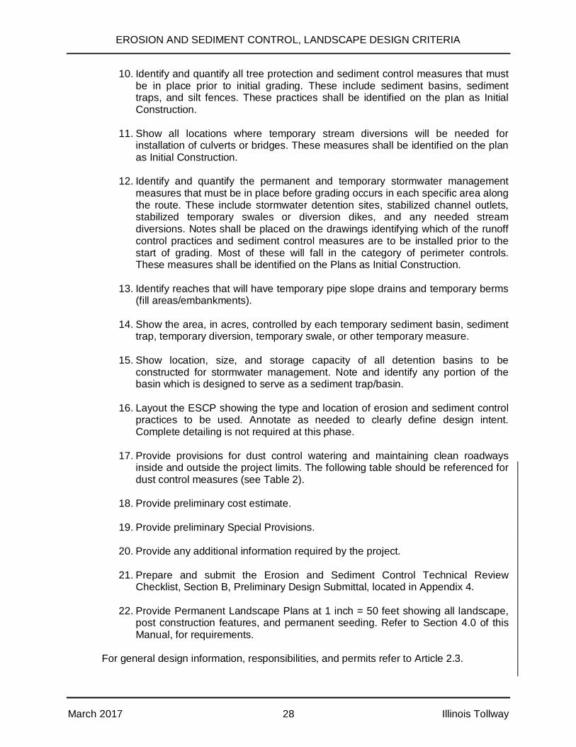
March 2017 28 Illinois Tollway
10. Identify and quantify all tree protection and sediment control measures that mustbe in place prior to initial grading. These include sediment basins, sedimenttraps, and silt fences. These practices shall be identified on the plan as InitialConstruction.
11. Show all locations where temporary stream diversions will be needed forinstallation of culverts or bridges. These measures shall be identified on the planas Initial Construction.
12. Identify and quantify the permanent and temporary stormwater managementmeasures that must be in place before grading occurs in each specific area alongthe route. These include stormwater detention sites, stabilized channel outlets,stabilized temporary swales or diversion dikes, and any needed streamdiversions. Notes shall be placed on the drawings identifying which of the runoffcontrol practices and sediment control measures are to be installed prior to thestart of grading. Most of these will fall in the category of perimeter controls.These measures shall be identified on the Plans as Initial Construction.
13. Identify reaches that will have temporary pipe slope drains and temporary berms(fill areas/embankments).
14. Show the area, in acres, controlled by each temporary sediment basin, sedimenttrap, temporary diversion, temporary swale, or other temporary measure.
15. Show location, size, and storage capacity of all detention basins to beconstructed for stormwater management. Note and identify any portion of thebasin which is designed to serve as a sediment trap/basin.
16. Layout the ESCP showing the type and location of erosion and sediment controlpractices to be used. Annotate as needed to clearly define design intent.Complete detailing is not required at this phase.
17. Provide provisions for dust control watering and maintaining clean roadwaysinside and outside the project limits. The following table should be referenced fordust control measures (see Table 2).
18. Provide preliminary cost estimate.
19. Provide preliminary Special Provisions.
20. Provide any additional information required by the project.
21. Prepare and submit the Erosion and Sediment Control Technical ReviewChecklist, Section B, Preliminary Design Submittal, located in Appendix 4.
22. Provide Permanent Landscape Plans at 1 inch = 50 feet showing all landscape,post construction features, and permanent seeding. Refer to Section 4.0 of thisManual, for requirements.
For general design information, responsibilities, and permits refer to Article 2.3.

EROSION AND SEDIMENT CONTROL, LANDSCAPE DESIGN CRITERIA
March 2017 29 Illinois Tollway
Table 2:Applicability of Dust Control Measures for Various Site Conditions
Disturbed AreaNo Traffic
Disturbed AreaWith Traffic Soil Stockpiles Clearing/
ExcavatingSite Exitto Road
• Seeding• Mulching• Watering•Chemical Application
• Watering•Chemical Application•Temporary Gravel or Paved Road
• Seeding• Mulching•Watering•Chemical Application
•Seeding•Mulching•Watering•Chemical Application
•Temporary Gravel or Paved Entrance•Truck Washdown Area•Daily Roadway Sweeping/ Cleaning
3.1.5 Pre-Final Design Submittal
The erosion and sediment control submittal for this phase shall include the plans, specifications,and cost estimate submitted at the Preliminary Design Phase developed to a 99% level ofcompleteness. Submit permit applications and backup data, including NPDES Notice of Intent(NOI), and CSMA (if required) submittal at 100% level for use by Illinois Tollway in permitsubmittals. Items to be addressed or included in this submittal are:
A. Address, in writing, all Illinois Tollway comments from previous submittal.
B. Identify any erosion or sediment control measure that will serve as a permanenterosion or sediment control measure after construction is complete.
C. Identify number, volume, length, width, bottom elevation, and cleanout elevation ofsediment traps and sediment basins. These shall be shown on the drawings.
D. Include sediment traps, sediment basins, dewatering basins, temporary swales, andtemporary channel diversions drawings on the cross sections. Submit these forreview to verify that the devices will fit in the intended area.
E. Label the specific location(s), size, and length of all erosion and sediment controlmeasures shown of the drawings.
F. Provide the dimension, material, and installation details for all erosion and sedimentcontrol measures and facilities not covered by the Standard Drawings.
G. Provide a maintenance schedule for any special measures not covered in thestandard drawings and specifications.
H. Provide Pre-Final cost estimate.
I. Provide Pre-Final Special Provisions.
EROSION AND SEDIMENT CONTROL, LANDSCAPE DESIGN CRITERIA
March 2017 30 Illinois Tollway
J. Prepare SWPPP. The SWPPP shall not be considered complete until the Designerhas prepared the site description, along with identification, implementation, andmaintenance of BMPs to reduce pollutants in stormwater discharges. This is requiredto comply with the provisions of the NPDES Permit Number ILR10 issued by theIEPA for stormwater discharges from construction site activities. The Designer shallmodify Special Provision 111.2 to satisfy this requirement.
K. Provide any additional information required by the project.
L. Provide the NPDES NOI form.
M. Provide CSMA submittal (if required). Include two full size sets of Erosion andSediment Control Plans, one reduced size set, and three sets of submittaldocuments.
N. Prepare and submit the Erosion and Sediment Control Technical Review Checklist,Section C, Pre-Final Design Submittal, located in Appendix 4.
3.1.6 Final Design Submittal
The erosion and sediment control submittal for this phase shall include the plans, specifications,and cost estimate developed to a 100% level of completeness. Items to be addressed orincluded in this submittal are:
A. Address, in writing, all Illinois Tollway comments from previous submittal.
B. Provide final Overview and ESCP Drawings.
C. Provide final Special Provisions and SWPPP in Special Provision 111.2.
D. Provide final cost estimate.
E. Provide Professional Engineer’s seal and signature on the plans.
F. Provide any additional information required by the project.
G. Prepare and submit the Erosion and Sediment Control Technical Review Checklist,Section D, Final Design Submittal, located in Appendix 4.
3.1.7 References
Please refer to the Illinois Tollway’s website for the most recent guidance documents, includingIllinois Tollway Standard K1 and applicable Section M Base Sheet Drawings and Specifications.
IEPA's National Pollutant Discharge Elimination System (NPDES) Stormwater Permit No.ILR10, - General Permit for Stormwater Discharges Associated with Construction Sites.
Illinois Urban Manual, AISWCD, IEPA, and NRCS
Illinois Department of Transportation (IDOT) – Bureau of Design and Environmental Manual,Chapter 41 – Construction Site Storm Water Pollution Control
EROSION AND SEDIMENT CONTROL, LANDSCAPE DESIGN CRITERIA
March 2017 31 Illinois Tollway
Appendix 4, Illinois Tollway Erosion and Sediment Control Plan Technical ReviewChecklist.
3.2 Design Criteria
All runoff, erosion, and sediment control measures shall be reviewed to ensure that roadsidehazards are not created. In no instance shall control measures be located in or near the clearzone.
3.2.1 Runoff Control
Runoff plays an important role in soil and sediment erosion, as well as collecting and moving thechemicals (i.e., nutrients and pesticides) from soil and vegetative cover. Runoff control appliesboth to the on-site and off-site runoff.
A. On-site runoff is generally either conveyed through the site or stored on-site.
· Runoff conveyance is generally done through temporary or permanent ditches,swales, or channels, and is intended to convey the runoff generated within theproject area through the site. The conveyance facilities shall be designedaccording to the Illinois Tollway DDM and protected against erosion, usingtemporary and/or permanent erosion control measures.
· Storage of on-site runoff can be done using temporary or permanent detentionbasins.
B. Off-site runoff shall generally be diverted from the construction site using diversiondikes and diversion channels. The diversion shall not cross the watershed drainageboundaries for the site. If diversion is not possible, the off-site runoff is to beconveyed through the site in such manner that untreated on-site runoff does not mixwith the off-site runoff. Generally, the off-site runoff shall outlet into an undisturbed ora stabilized area, at a non-erosive velocity. The diversion channels shall be designedand constructed to withstand the expected velocity for the 25 year, 24 hourfrequency storm without erosion. All constructed or modified channels shall bestabilized within 48 hours. If separation of on-site and off-site runoff is not possible,size sediment traps, basins, and other measures for both on-site and off-site runoff.
C. The following is a brief description of possible erosion control measures that willachieve runoff control.
· Temporary ditch checks or rock check dams shall be used in the existing,proposed, and temporary ditches to control velocity. These types of erosioncontrol practices are not intended to trap sediment, but are used as a temporarymeasure to control velocity. The spacing between ditch checks and rock checkdams shall be determined as shown in Figure 1 (Article 3.1.2C) or according tomanufacturer’s requirements.
EROSION AND SEDIMENT CONTROL, LANDSCAPE DESIGN CRITERIA
March 2017 32 Illinois Tollway
· Diversion dikes shall be used to route off-site flows away from disturbed areas.The diverted runoff from an undisturbed area shall outlet into an undisturbed or astabilized area at non-erosive velocities.
· Temporary channel diversion shall be used to carry existing stream flow throughor around the construction site. A dewatering discharge basin shall be providedwith either a minimum storage capacity (in cubic feet) equal to the dewateringpump capacity (in gallons per minute) times 32, or a minimum size of 10 feet x 10feet x 3 feet in depth, whichever is more stringent.
3.2.2 Erosion Control
A. Erosion control can be done through several measures that:
· limit the exposure duration of the unprotected soil to the erosion factors, and/or
· ensure the proper temporary and permanent soil protection; i.e., throughvegetative measures or structural measures.
B. The following general criteria shall be used for the design of vegetative and structuralerosion control measures as part of Illinois Tollway projects.
1. All necessary erosion and sediment control measures shall be constructed andfunctional prior to initiating clearing, grading, stripping, excavating, or fillactivities. Illinois Tollway Standard K1 and Section M Base Sheet Drawingscontain the general rules that shall be followed and the standard symbols thatshall be used for the erosion and sediment control measures.
2. Disturbed areas are to be protected from erosion in a timely manner. Erosionstabilization measures shall be initiated within 1 day, in portions of the site whereconstruction activities have temporarily or permanently ceased, except portionsof the construction site where activities will resume within 14 days (e.g., the totaltime period that construction activity is temporarily ceased will be less than 14days). Adjacent sediment control measures shall remain continuously in placeduring construction.
Same day stabilization is to be implemented as outlined in the Illinois TollwaySupplemental Specification Article 280.15(c). Same day stabilization is typicallyused to minimize erosion and the movement of soils at those areas shown on theplans or directed by the CM. Same day stabilization is typically performed eachday any soil disturbance occurs as a result of Contractor’s operations. Theprimary method to perform same day stabilization is through the use ofTemporary Stabilization with straw mulch, with permanent measures installed atthe earliest opportunity. This item generally provides for the additional labor thatmay be required to perform the continuous soil stabilization work needed toreduce sediment loss where limited space is available for sediment controlmeasures.
3. Site plans shall show the existing vegetation that is to be preserved wherepossible, and disturbed portions of the site that shall be stabilized. Stabilization

EROSION AND SEDIMENT CONTROL, LANDSCAPE DESIGN CRITERIA
March 2017 33 Illinois Tollway
practices shall include temporary seeding, permanent seeding, mulching, geo-textiles, sod stabilization, vegetative buffer strips, protection of trees,preservation of mature vegetation, or other appropriate non-vegetativemeasures.
4. Areas having slopes greater than 1:10 (V:H) shall be stabilized with erosionblankets in combination with permanent seeding as soon as possible. Providetemporary seeding and appropriate mulch or erosion control blanket controlmeasures on all slopes if permanent seeding is not immediately installed.
5. Channel lining shall be provided where the design discharge velocity exceeds thescour velocity of the soil. See Article 4.2.10 B. Treatment of Drainage Channelsand Ditches for guidance.
6. Permanent riprap protection and fabric formed concrete mats shall be avoided onIllinois Tollway drainage facilities due to maintenance difficulties. Open cell,articulated concrete block mats or other environmentally friendly methods suchas turf reinforcement mats with open patterns and cost effective products shall beconsidered. Refer to Illinois Tollway DDM, Ditch and Channel Design forpermanent erosion control measures.
7. Each site shall have stabilized construction entrance(s).
8. In some cases, when there is limited space available for sediment traps or othercontrol measures, “same day stabilization” shall apply.
3.2.3 Sediment Control
Sediment is the most common non-point source of pollutants. The design of Illinois Tollwaysediment control measures shall consider the following general principles.
A. For disturbed areas draining less than 1 acre, filter barriers (including silt fences orequivalent control measures) shall be constructed to control all runoff leaving thesite. Generally, these are appropriate sediment control measures for small drainageareas where concentrated flow is not present. Vegetative filter strips, with a minimumwidth of 50 feet, may be used as an alternative in areas where only sheet flow runoffis expected. In areas of high environmental significance, concentrated flow, or wherethe ponded water depth may exceed 18 inches, a super silt fence shall be provided.
B. For disturbed areas draining more than 1 acre but less than 5 acres, a sediment trapor sediment basin shall be constructed at the down-slope point of the disturbed area.Sediment traps will normally adequately control the sediment in areas whereconcentrated flow is likely to be present.
C. For disturbed areas draining more than 5 acres, a sediment basin shall be providedat the down-slope point of the disturbed area. A maximum of 20 acres may bedisturbed at a single time. The sediment traps or basins shall be designed to store3600 cubic feet per acre for the entire on-site and off-site drainage area tributary tothe basin, or as determined necessary by soil erosion calculations. Where reducedsized basins will be used, a general note needs to be added on the erosion controlplans indicating that these traps/basins shall need to be cleaned out more frequently.

EROSION AND SEDIMENT CONTROL, LANDSCAPE DESIGN CRITERIA
March 2017 34 Illinois Tollway
This shall be properly reflected in the quantity estimate for “Erosion and SedimentControl – Clean-out”.
D. Design of any stormwater detention basin shall be coordinated with the need forsediment traps or basins. If properly designed, located, and maintained, thepermanent detention basins can be easily modified to serve as temporary sedimentbasins until the project area is stabilized.
E. Temporary pipe slope drains shall be used to convey runoff from the top of fill slopesto conveyance systems at the base of slopes as the embankments are constructed.Pipe slope drains are to remain in place until gutters or shoulders are constructedand the slopes are seeded and mulched, or otherwise stabilized.
F. Anionic flocculent polymers (PAMs) may also be applied where extreme turbidityexists and/or as a pre-treatment for sediment laden water, before draining intosediment traps or basins.
All temporary and permanent erosion and sediment control measures shall be inspected,maintained, and repaired as needed to assure effective performance of their intended function.At a minimum, contractor shall inspect measures weekly and within 24 hours of a rainfall eventwith 0.5 inch or greater of precipitation (5 inches of snow).
Upon completion of construction and/or permanent stabilization, temporary erosion andsediment control measures shall be removed. (Temporary erosion control measures may be leftin place for a period of time following construction if construction included rubblized/recycledconcrete.) Temporary erosion and sediment control measures cannot be left in place on apermanent basis unless consistent with standards from the Illinois Tollway DDM. In no instancemay riprap or ditch checks be left in place unless the CM gets written acceptance from theIllinois Tollway Environmental Unit and it is not a hazard to the motorist.
3.2.4 Control Practices and Applications
For the ESCP to be implemented correctly, practices need to be applied within their intendeduse. The following is provided to help guide the Designer and CM.
Refer to the latest Illinois Tollway Supplemental Specifications Section 280 for detaileddescriptions of control practices and pay items. Refer to Standard K1 and applicable Section MBase Sheet Drawings for control device details and construction notes. The Illinois UrbanManual (IEPA/NRCS) and Bureau of Design and Environmental Manual, Chapter 41 (IDOT)may also be used for reference.
A. Dust Control
Pay items:
JS107361 - APPLY DUST SUPPRESSION AGENTSJS107362 - SOIL STABILIZERS

EROSION AND SEDIMENT CONTROL, LANDSCAPE DESIGN CRITERIA
March 2017 35 Illinois Tollway
Description and Purpose:
This item, discussed in Article 107.36 of the Illinois Tollway Supplemental Specifications,consists of applying water or chemical products to exposed soil surfaces to prevent themovement of dust that may be harmful to human health or the environment. Dustcontrols reduce the surface and air transport of dust, thereby preventing pollutants frominfiltrating into stormwater.
Application:
· This item is to be used to control dust resulting from construction operationsexclusively.
· The Designer shall prepare a Dust Control Plan in accordance with Article 107.36of the Illinois Tollway Supplemental Specifications. The Plans and SpecialProvisions shall be coordinated with this Dust Control plan.
· Dust Control Watering can provide onsite control of fugitive dust on haul roadsand disturbed surfaces on an as-needed basis. The frequency of wateringdepends on several factors, including weather, soil type, and construction traffic.Water treatment is typically only effective for 0.5 hour to 12 hours. Water shall beapplied at a rate so that the soil surface is wet, but not saturated or muddy. Ifwatering is to be employed, conditions shall be monitored to prevent mud frombeing spread on local streets.
· Dust Control Watering shall consist of the uniform application of sprinkled water,and shall be applied only when directed and in a manner accepted by the CM.
· The Dust Control Watering pay item shall not be used in the compaction of earthembankments.
· Dust Suppression Agents are a mid to long term measure, may require multipleapplications per year. They shall be applied according to manufacturers’recommendations, and according to the guidance in the IDOT Bureau of Designand Environmental Manual, Article 41-2.03.
· Chloride, gypsum or plaster-type sprayable mulches cannot be used without prioracceptance from the Illinois Tollway Environmental Unit.
Also see Section 4 of this Manual – Landscape, for the following items:
· Standard and Illinois Tollway Supplemental Specifications Section 250 – Seeding
· Standard and Illinois Tollway Supplemental Specification Section 251 – Mulch
B. Management of Erosion and Sediment Control
Pay Item:
JS280020 - MANAGEMENT OF EROSION AND SEDIMENT CONTROL
EROSION AND SEDIMENT CONTROL, LANDSCAPE DESIGN CRITERIA
March 2017 36 Illinois Tollway
Description and Purpose:
This item, described in Article 280.02 of the Illinois Tollway Supplemental Specifications,consists of the management and maintenance of erosion and sediment control aspectsof the project. This item includes inspections, meetings, schedule adherence,maintenance, and repair of erosion and sediment control items. It generally requires noaction by the Designer, unless there are unique project conditions requiring a SpecialProvision.
Application:
· This item is to be used for all projects requiring erosion and sediment controlmeasures for the duration necessary to ensure compliance with NPDES permit,contract plans, and specifications.
C. Erosion and Sediment Control – Excavation
Pay Item:
JS280030 - EROSION AND SEDIMENT CONTROL-EXCAVATION
Description and Purpose:
This item, described in Article 280.03 of the Illinois Tollway Supplemental Specifications,is comprised of earth and rock excavation associated with erosion control construction.
Application:
· This item to be used for excavation of sediment basins, sediment traps,dewatering basins, temporary swales, and temporary channel diversions.
· This item does not include excavation of permanent ditches parallel to theroadway, at the toe of embankments, or at the top of cuts.
· This item includes locating, detailing, constructing, and maintaining concretetruck washout areas within the Contract Limits, as well as their removal andrestoration.
D. Erosion and Sediment Control – Cleanout
Pay Item:
JS280040 - EROSION AND SEDIMENT CONTROL-CLEANOUT
EROSION AND SEDIMENT CONTROL, LANDSCAPE DESIGN CRITERIA
March 2017 37 Illinois Tollway
Description and Purpose:
This item, described in Article 280.04 of the Illinois Tollway Supplemental Specifications,consists of the excavation required for the removal of accumulated sediment. Sedimentshall be removed from devices when 50% full or when 50% of the device height isreached.
Application:
· Use this item whenever Erosion and Sediment Control – Excavation, is used.
· This item also consists of excavation required for the removal of accumulatedsediment, vegetation, and debris from traps, basins, and the areas adjacent tosilt fences, super silt fences, rectangular inlet protection, filter fabric inletprotection, ditch checks, and any other clean out excavation of accumulatedsediment.
E. Silt Fence
Pay Item:
JS280050 - SILT FENCE
Description and Purpose:
A silt fence is a temporary, linear sediment barrier of permeable fabric designed tointercept and slow the flow of sediment-laden sheet flow runoff. Silt fences allowsediment to settle from runoff before water leaves the construction site. This item isdescribed in Article 280.05 of the Illinois Tollway Supplemental Specifications.
Application:
· Silt fences shall be employed:
· below the toe of exposed and erodible slopes,
· down-slope of exposed soil areas,
· around temporary stockpiles, and
· along streams and channels.
· Silt fences serve little purpose as perimeter fencing, unless they are emplaced tointercept off-site sediment from entering the project. In those cases, permanentsediment interception and control measures should be considered.
· Silt fences help contain water to allow sediment to deposit, they do not filtersediment from runoff water.

EROSION AND SEDIMENT CONTROL, LANDSCAPE DESIGN CRITERIA
March 2017 38 Illinois Tollway
· This device is to be used to control sheet flow only, do not use for concentratedflows, drainage channels, or above or below drainage pipes.
· Maximum drainage area for sheet flow shall not exceed ½ acre per 100 feet ofsilt fence.
· To function properly, silt fences should be constructed along the contour lines toprevent concentration of flow, which increases the likelihood of silt fence failure.
· When silt fence is used to create a small containment system, the end posts shallbe turned uphill to prevent water from flowing around the ends.
· Silt fence barriers shall not be used as mid-slope protection where slopes aresteeper than 1:4 (V:H). Sediment rolls shall be used under those conditions.
· Silt fence barriers shall not be employed where water ponding behind the siltfence may cause flooding or fence failure, or where washout of the silt fence maycause damage.
· Silt build up against the fence is to be inspected within 24 hours of rainfall eventwith 0.5 inch or greater of precipitation (5 inches of snow) and removed whenbulges develop in the fence, or when silt reaches 50% of fence height.
· Reference Standard Drawing K1 for additional information.
· Additional reference on silt fencing can be found in Article 41-3.01(b) of the IDOTBureau of Design and Environmental Manual, Chapter 41.
F. Re-Erect Silt Fence
Pay Item:
JS280051 - RE-ERECT SILT FENCE
Description and Purpose:
This item, described in Article 280.05(b) of the Illinois Tollway SupplementalSpecifications, consists of re-erecting silt fencing damaged by natural causes.
Application:
· This item to be used for replacement of the silt fence that has become damagedor ineffective as a result of natural forces.
· Silt fence damaged by the Contractor’s operations or negligence shall not be re-erected under this item.
· If damage to silt fence has been caused by high flow volumes, or if damage isanticipated from heavy containment, replacement with super silt fence should beconsidered.
EROSION AND SEDIMENT CONTROL, LANDSCAPE DESIGN CRITERIA
March 2017 39 Illinois Tollway
G. Temporary Swales
Pay Items:
JS280060 - TEMPORARY SWALE, TREATMENT TYPE IJS280061 - TEMPORARY SWALE, TREATMENT TYPE IIJS280062 - TEMPORARY SWALE, TREATMENT TYPE III
Description and Purpose:
A temporary swale is an excavated drainage way designed to prevent runoff fromentering disturbed areas by intercepting and diverting it to a stabilized outlet, or tointercept sediment laden water and divert it to a sediment-trapping device. This item isdescribed in Article 280.06 of the Illinois Tollway Supplemental Specifications. Thismeasure requires the Designer to prepare a design plan detail; reference Illinois Tollwayapplicable Base Sheet in Section M.
Application:
· To intercept and divert runoff from one undisturbed area to another undisturbedstabilized area at non-erosive velocity.
· To transport off-site flows across disturbed areas such as right-of-way.
· All temporary swales shall have uninterrupted positive grade to an outlet.
· To intercept sediment laden water from a disturbed area and divert it to asediment trapping device.
· Diverted runoff from an undisturbed area shall outlet directly into an undisturbed,stabilized area at a non-erosive velocity.
· Hydraulic design of temporary swales shall accommodate a 25-year, 24-hourstorm frequency. In cases where temporary swale failure would endanger theroadway or other Illinois Tollway facilities, hydraulic design shall accommodatethe 50-year event. The lining design shall accommodate a 10-year, 24-hourstorm.
· For Temporary Swale, Treatment Type l, consisting of temporary ground coverand a heavy duty erosion control blanket, the maximum channel velocity shall notexceed the manufacturer’s recommended velocity for the erosion blanket.Generally, channel slope should not exceed 3%.
· For Temporary Swale, Treatment Type lI, consisting of course aggregate CA3for ditch lining, 3 inches in thickness over a geotextile filter fabric (designed foruse with riprap), pressed into the soil with construction equipment, the maximumchannel velocity shall not exceed 3 feet per second. Generally, channel slopeshould not exceed 5%.
EROSION AND SEDIMENT CONTROL, LANDSCAPE DESIGN CRITERIA
March 2017 40 Illinois Tollway
· For Temporary Swale, Treatment Type lII, consisting of gradation RR3 riprap in alayer at least 8 inches thick over a geotextile filter fabric (designed for use withriprap), pressed into the soil, the maximum channel velocity shall not exceed 4.5feet per second. Temporary Swales may require the design of a velocitydissipation device at their outlet, to prevent localized erosion. Generally, channelslope should not exceed 8%.
· Temporary swales may require the design of a velocity dissipation device at theiroutlet to prevent localized erosion.
· Swales collecting runoff from disturbed areas shall be specified to remain inplace until the disturbed areas are permanently stabilized.
· The use of Type II and Type III Treatments shall be approved by the IllinoisTollway Environmental Unit.
· Additional reference on drainage swales can be found in Article 41-2.04(a) of theIDOT Bureau of Design and Environmental Manual, Chapter 41.
H. Stabilized Construction Entrance
Pay Item:
JS280070 - STABILIZED CONSTRUCTION ENTRANCE
Description and Purpose:
A stabilized construction access, described in Article 280.07 of the Illinois TollwaySupplemental Specifications, is defined as a point of entrance/exit to a construction sitethat is stabilized to reduce the tracking of mud and dirt onto public roads by constructionvehicles. Tire wash stations shall be considered where stabilized exits may notsufficiently remove sediment.
Application:
· Place stabilized entrance at all points of construction ingress and egress.
· Reference Standard Drawing K1 for additional information.
· Additional reference on stabilized construction entrances can be found in Article41-3.06(a) of the IDOT Bureau of Design and Environmental Manual, Chapter 41
I. Flotation Boom
Pay Item:
JS280080 - FLOTATION BOOM
EROSION AND SEDIMENT CONTROL, LANDSCAPE DESIGN CRITERIA
March 2017 41 Illinois Tollway
Description and Purpose:
A flotation boom, described in Article 280.08 of the Illinois Tollway SupplementalSpecifications, is designed specifically to contain and control the dispersion of turbidityand silt in a water body caused by marine construction, shoreline work, pile driving,dredging activities, and other site work. Floating turbidity barriers consist of a topflotation boom, a fabric curtain extending downward under water, and a heavygalvanized steel chain sealed into a hem along the bottom of the curtain to provideballast.
Application:
· This item to be used to control turbidity encountered during construction whenworking in a stream or waterway.
· Install and anchor floatation boom to one shoreline of stream or waterway inaccordance with manufacturer’s recommendations, to prevent drift towards theshore or downstream. Booms shall not be perpendicular to the flow of a flowingbody of water.
· Bottom of boom shall be weighted to reach the bottom of the waterway.
· Reference Standard Drawing K1 for additional information.
J. Super Silt Fence
Pay Item:
JS280100 - SUPER SILT FENCE
Description and Purpose:
A super silt fence, described in Article 280.10 of the Illinois Tollway SupplementalSpecifications, is designed to handle a higher amount of water and silt runoff or sensitiveareas. It features a permeable fabric and chain link fence. Super silt fence is capable ofwithstanding more severe erosion conditions while providing maximum protection incritical landscapes.
Application:
· This item to be used to protect wetlands and other environmentally sensitiveareas.
· This item is to be used to control high sheet flow volumes. Maximum drainagearea shall not exceed 1/2 acre per 100 feet of fence. Under sheet flow conditions,Super Silt Fence should be constructed along the contour lines (as with silt fenceinstallation).
· This item shall not be used in ditches or obstruct flow of drainage channels.
EROSION AND SEDIMENT CONTROL, LANDSCAPE DESIGN CRITERIA
March 2017 42 Illinois Tollway
· Reference Standard Drawing K1 for additional information.
· Silt build up against fence shall be inspected within 24 hours of rainfall event with0.5 inch or greater of precipitation (or 5 inch of snow) and removed when bulgesdevelop in the fence, or when silt reaches 50% of fence height.
K. Temporary Pipe Slope Drain
Pay Item:
JS280110 - TEMPORARY PIPE SLOPE DRAINS
Description and Purpose:
A slope drain, described in Article 280.11 of the Illinois Tollway SupplementalSpecifications, is a pipe used to intercept and direct surface runoff or groundwater downthe face of unstabilized slopes in order to minimize erosion on the slope face. Slopedrains discharge into a stabilized watercourse, trapping device, or stabilized area. Slopedrains are used with lined ditches to intercept and direct surface flow away from slopeareas to protect cut or fill slopes.
Slope drains are generally used in conjunction with earthen dikes (berms) that direct therunoff to the temporary pipe slope drain with flared end section. This measure requiresthe Designer to prepare a design plan detail. Reference Illinois Tollway Base Sheet inSection M.
Application:
· This item shall be used to control erosion on the embankment slope face duringconstruction of the embankment.
· Maintain device in place until shoulders are constructed and embankment slopesare seeded and mulched.
· At the end of each day of embankment construction, temporary pipe slope drainshall be extended to the top of the embankment.
· Discharge from pipe slope drain shall release into sediment trap, into sedimentbasin, or to a stabilized ditch discharging to a trap or basin.
· Design criteria for capacity, dike, pipe size, spacing, inlet, and outlet shall be inaccordance with the Illinois Urban Manual.
· Additional reference on slope drains can be found in Article 41-2.04(b) of theIDOT Bureau of Design and Environmental Manual, Chapter 41.
EROSION AND SEDIMENT CONTROL, LANDSCAPE DESIGN CRITERIA
March 2017 43 Illinois Tollway
L. Tree Protection
Pay Item:
JS280120 - TREE PROTECTION
Description and Purpose:
A tree protection zone, described in Article 280.12 of the Illinois Tollway SupplementalSpecifications, is established using temporary fencing in order to protect the critical rootarea important to the tree’s health.
Application:
· This item to be used to protect trees from disturbance and from equipmenttraveling over the root zone. It shall be used for trees identified to be protected inthe Tree Preservation Plans.
· Tree protection should be erected for single trees, or around groups of trees,according to the judgment of the Designer.
· Tree protection fence shall be high visibility plastic or other approved materialthat can last through the duration of the protection period.
· Tree protection shall be constructed as part of Initial Construction, prior tostarting grading.
· Locate fence outside the drip line of the tree or trees to be saved, and in no casecloser than 5 feet to the trunk of any tree.
· Reference Standard Drawing K1 for additional information.
· See Standard Specifications Section 201 – Clearing, Tree Removal andProtection, Care and Repair of Existing Plant Material.
M. Temporary Riprap
Pay Items:
JS280140 - TEMPORARY RIPRAP28200200 - FILTER FABRIC
Description and Purpose:
Riprap, described in Article 280.14 of the Illinois Tollway Supplemental Specifications, isa layer of large stones used to protect soil from erosion in areas of concentrated runoff.Riprap can also be used on slopes that are unstable because of seepage problems. Thisitem consists of placing a geotextile fabric and a protective coating of dumped or hand-laid stone for rock check dams, stone outlet structure sediment traps, dewatering basins,temporary swales, diversion dikes, and aggregate berms as shown on the Plans, and
EROSION AND SEDIMENT CONTROL, LANDSCAPE DESIGN CRITERIA
March 2017 44 Illinois Tollway
the removal of the riprap and geotextile upon completion of the need for these temporaryfacilities. Temporary erosion control measures cannot be left in place on a permanentbasis unless consistent with standards from the Illinois Tollway DDM and it is not ahazard to the motorist. In addition, the CM shall obtain written acceptance from theIllinois Tollway Environmental Unit for the allowance of the use of temporary erosioncontrol measures on a permanent basis.
Application:
· Use riprap to stabilize cut-and-fill slopes; channel side slopes and bottoms; inletsand outlets for culverts, bridges, slope drains, grade stabilization structures,storm drains; streambanks and grades; and as rock check dams.
· Temporary erosion control measures cannot be left in place on a permanentbasis unless consistent with standards from the Illinois Tollway DDM.
· In no instance may riprap or ditch checks be left in place unless the CM getswritten approval from the Illinois Tollway Environmental Unit. In no instance shallriprap be located in the clear zone.
· Riprap installations shall be designed to accommodate the flow velocity, andshall be designed in accordance with Article 41-2.05(a) of the IDOT Bureau ofDesign and Environmental Manual, Chapter 41, and the IDOT Drainage Manual.
· Filter fabric is to be installed under all riprap.
N. Temporary Stabilization with Straw Mulch
Pay Item:
JS280150 - TEMPORARY STABILIZATION WITH STRAW MULCH
Description and Purpose:
Seed stabilization with straw mulch and tackifier, described in Article 280.15 of theIllinois Tollway Supplemental Specifications, consists of placing temporary seed followedby a uniform layer of straw and anchoring it with a stabilizing tackifier. This method isused as a temporary erosion control method to stabilize the soil and reduce erosioncaused by wind and water.
Application:
· This item is for the combination of both temporary seed and temporary mulchingof areas that cannot at the time be stabilized with permanent vegetativemeasures.
· This item shall be used for temporary erosion control where slopes are 1:3 (V:H),or flatter.
EROSION AND SEDIMENT CONTROL, LANDSCAPE DESIGN CRITERIA
March 2017 45 Illinois Tollway
· Erosion control blanket or alternate mulch methods should be considered fortemporary erosion control on steeper slopes when temporary stabilization withstraw mulch are not effective
· Gypsum or plaster-type sprayable tackifiers shall not be used without priorapproval from the Illinois Tollway Environmental Unit.
· This item shall not be used in areas where concentrated flows occur. In thosecases, consider the use of Erosion Blanket, Turf Reinforcement Mat (With openpatterns), sodding, or sediment control devices.
· Provide if a portion of the work is to be exposed without activity for more than 14days. (See Article 3.1.2 D. Soils, Excavation, and Disturbed Areas.)
· Additional reference on straw mulch can be found in Article 41-2.02(a) of theIDOT Bureau of Design and Environmental Manual, Chapter 41.
O. Same Day Stabilization
Pay Item:
JS280151 - SAME-DAY STABILIZATION
Description and Purpose:
Same day stabilization is to be implemented as outlined in the Illinois TollwaySupplemental Specification Article 280.15(c). Same day stabilization is typically used tominimize erosion and the movement of soils at those areas shown on the plans ordirected by the CM. Same day stabilization is typically performed each day for any areaof soil disturbed as a result of Contractor’s operations. The primary method to performsame day stabilization is through the use of Temporary Stabilization with Straw Mulch,with permanent measures installed at the earliest opportunity. This item generallyprovides for the additional labor that may be required to perform the continuous soilstabilization work needed to reduce sediment loss where limited space is available forsediment control measures.
Application:
· Same day stabilization is to be implemented when perimeter and secondarycontrols are not in place due to limited available work space or in environmentallysensitive areas.
· Same day stabilization may consist of either temporary erosion control measuresor the permanent landscaping indicated on the plan. The permanent landscapingshall be implemented as the same day stabilization whenever possible. Thismeans that the Contractor shall stage his work so that portions of the slopes andditches can be brought to finished grade, topsoiled, and landscaped prior to theend of the workday.
EROSION AND SEDIMENT CONTROL, LANDSCAPE DESIGN CRITERIA
March 2017 46 Illinois Tollway
· When permanent landscaping is not possible, due either to construction stagingor specification constraints, same day stabilization shall consist of temporaryerosion control measures. The primary erosion control method used along withsame day stabilization during grading operations shall be Temporary Stabilizationwith straw mulch.
· The Designer shall indicate on the plans which specific items or limits are subjectto Same Day Stabilization.
P. Diversion Dike
Pay Items:
JS280160 - DIVERSION DIKE, TREATMENT TYPE IJS280161 - DIVERSION DIKE, TREATMENT TYPE IIJS280162 - DIVERSION DIKE, TREATMENT TYPE III
Description and Purpose:
A diversion dike, described in Article 280.16 of the Illinois Tollway SupplementalSpecifications, is an earthen perimeter control consisting of a ridge of compacted soil,often accompanied by a ditch or swale at the top or base of a sloping disturbed area,constructed to control the velocity of or route sediment-laden stormwater runoff. Thismeasure requires the Designer to prepare a design plan detail. Reference IllinoisTollway Base Sheet in Section M.
When on the upslope side of a site, earthen perimeter controls help to prevent surfacerunoff from entering a disturbed construction site. An earthen structure located upslopecan improve working conditions on a construction site. It can prevent an increase in thetotal amount of sheet flow runoff traveling across the disturbed area and thereby lessenerosion on the site.
Earthen perimeter control structures also can be located on the downslope side of a site.They divert sediment-laden runoff created onsite to onsite sediment-trapping devices,preventing sediment from leaving the disturbed area.
Application:
· To intercept and divert runoff from an undisturbed area to an undisturbedstabilized area at non-erosive velocity.
· To intercept sediment laden water and divert it to a sediment trapping device.
· All dikes shall have positive drainage to an outlet.
· Design criteria shall be in accordance with the Illinois Urban Manual.
· Dike and embankment flow stabilization dimensioning to be sized for thedrainage area.
EROSION AND SEDIMENT CONTROL, LANDSCAPE DESIGN CRITERIA
March 2017 47 Illinois Tollway
· Design capacity to carry the peak runoff for a 100-year, 24-hour storm frequency.
· Earth dikes shall have an outlet that functions with a minimum of erosion. Runoffshall be conveyed to a sediment trapping device such as a sediment trap orsediment basin where either the dike channel or the drainage area above thedike is adequately stabilized.
· Diverted runoff from an undisturbed area shall outlet to an undisturbed, stabilizedarea at a non-erosive velocity.
· For Diversion Dike, Treatment Type l, consisting of temporary ground cover anda heavy duty erosion control blanket, the maximum channel velocity shall notexceed the manufacturer’s recommended velocity for the erosion blanket.
· For Diversion Dike, Treatment Type Il, consisting of course aggregate CA3 forditch lining, 3 inches in thickness over a geotextile filter fabric (designed for usewith riprap), pressed into the soil with construction equipment, the maximumchannel velocity shall not exceed 3 feet / second.
· For Diversion Dike, Treatment Type IIl, consisting of gradation RR3 riprap in alayer at least 8 inches thick over a geotextile filter fabric (designed for use withriprap), pressed into the soil, the maximum channel velocity shall not exceed 4.5feet / second.
· The use of Type II and Type III Treatments shall be approved by the IllinoisTollway Environmental Unit.
· Diversion dikes may require the design of a velocity dissipation device at theiroutlet, to prevent localized erosion.
· Additional reference on diversion dikes can be found in Article 41-2.04(a) of theIDOT Bureau of Design and Environmental Manual, Chapter 41.
Q. Dewatering Basins
Pay Items:
JS280030 - EROSION AND SEDIMENT CONTROL-EXCAVATIONJS280040 - EROSION AND SEDIMENT CONTROL-CLEANOUTJS280140 - TEMPORARY RIPRAPJS280190 - GEOTEXTILE FABRIC, CLASS C
Description and Purpose:
Dewatering basins, described in Article 280.17 of the Illinois Tollway SupplementalSpecifications, are structures designed to settle sediment from stormwater before itenters receiving waters. This measure requires the Designer to prepare a design plandetail. Reference Illinois Tollway Base Sheet in Section M.

EROSION AND SEDIMENT CONTROL, LANDSCAPE DESIGN CRITERIA
March 2017 48 Illinois Tollway
Application:
· A dewatering basin shall be installed wherever the Contractor is removing anddischarging water from excavated areas on the construction site and the water isnot being routed through an adequately sized sediment trap or sediment basin.The purpose of the basin is to temporarily store the discharged water and torelease it in a manner that causes the sediment laden water to be filtered prior torelease into a natural drainage way or stabilized conveyance.
· The minimum storage capacity of the Dewatering Basin in cubic feet shall be thedewatering pump capacity in gallons per minute times 32 or the minimum size:10 feet x 10 feet x 3 feet in depth, whichever is more stringent.
· Sediment to be removed when the basin is 50% full.
R. Rectangular Inlet Protection
Pay Item:
JS280180 - RECTANGULAR INLET PROTECTION
Description and Purpose:
Rectangular Inlet Protection, described in Article 280.18 of the Illinois TollwaySupplemental Specifications, is used at storm drain inlets located in unpaved areas, andthat are subject to runoff from construction activities. They are used to detain and/or filtersediment-laden runoff to allow sediment to settle and/or filter prior to discharge intostorm drainage systems or watercourses.
Application:
· This device is to be used to protect existing and new inlets, catch basins, andmanholes with open lids in non-paved areas.
· Maximum drainage area to each rectangular inlet protection device shall notexceed 1 acre.
· If Contractor prefers, super silt fence can be constructed around the inlet.
· Sediment shall be removed when silt reaches 50% of fence height.
· Reference Standard Drawing K1 for additional information.
S. Geotextile Fabric
Pay Item:
JS280190 - GEOTEXTILE FABRIC, CLASS C
EROSION AND SEDIMENT CONTROL, LANDSCAPE DESIGN CRITERIA
March 2017 49 Illinois Tollway
Description and Purpose:
Geotextile fabric, described in Article 280.19 of the Illinois Tollway SupplementalSpecifications, is an engineered textile designed to reinforce soil structures and toseparate fine grained from coarse grained materials.
Application:
· Geotextile fabric placed atop the ground surface is used to increase soil stabilityand provide for slope and fill erosion control.
· Geoweb is a cellular confinement structure used to stabilize infill and controlsshearing, as well as lateral and vertical movement for a load support system.Acting like a semi-rigid slab, it provides a stable base for unpaved surfaces forconstruction equipment loading.
· Additional reference on Geotextile Fabric can be found in StandardSpecifications Article 1080.02.
T. Filter Fabric Inlet Protection
Pay Item:
JS280205 - FILTER FABRIC INLET PROTECTION, COVER TYPEJS280210 – FILTER FABRIC INLET PROTECTION, BASKET TYPE
Description and Purpose:
Fabric Filter Protection devices, described in Article 280.20 of the Illinois TollwaySupplemental Specifications, are used at storm drain inlets in paved areas that aresubject to runoff from construction activities. They are used to detain and/or filtersediment-laden runoff and to allow sediment to settle, and/or to filter sediment prior todischarge into storm drainage systems or watercourses. The device consists of inletbasket and fabric insert, or inlet dam placed in front of curb inlet.
Application:
· Inlet dam shall not be used at pavement sags.
· This device shall be used to protect existing and new inlets, catch basins, andmanholes with open lids in paved areas only.
· Use only within paved areas if disturbed areas drain to paved areas. Use inconjunction with additional upstream protective measures, such as silt fence.
· Sediment shall be removed from fabric inlet basket and insert when 50% ofcapacity is reached.
· Sediment shall be removed from the perimeter of inlet dam when 50% of damheight is reached.
EROSION AND SEDIMENT CONTROL, LANDSCAPE DESIGN CRITERIA
March 2017 50 Illinois Tollway
· Field expedient inlet filters comprising a layer of geofabric laid under the inletcover shall be prohibited.
· Reference Standard Drawing K1 for additional information.
· Additional reference on inlet filter bags can be found in Article 41-3.02(a) and (b)of the IDOT Bureau of Design and Environmental Manual, Chapter 41.
U. Stone Outlet Structure Sediment Trap
Pay Items:
JS280030 - EROSION AND SEDIMENT CONTROL-EXCAVATIONJS280040 - EROSION AND SEDIMENT CONTROL-CLEANOUTJS280140 - TEMPORARY RIPRAPJS280190 - GEOTEXTILE FABRIC, CLASS C
Description and Purpose:
A sediment trap, described in Article 280.21 of the Illinois Tollway SupplementalSpecifications, is a containment area where sediment laden runoff is temporarilydetained under inactive conditions, allowing sediment to settle out before the runoff isdischarged. Sediment traps are formed by excavating or constructing an earthenembankment across a low drainage area. This measure requires the Designer toprepare a design plan detail. Reference Illinois Tollway Base Sheet in Section M.
Application:
· This practice is to be used to collect sediment laden water in existing, proposed,and temporary ditches/swales of all types.
· Design criteria shall be in accordance with the Illinois Urban Manual.
· The detention storage shall be composed of equal volumes of “wet” and “dry”detention storage.
· The wet and dry storage areas shall each be sized according to guidanceprovided by the Illinois Urban Manual or the IDOT Bureau of Design andEnvironmental Manual.
· The minimum length to width ratio for a sediment trap shall be 2:1.
· The spillway weir length shall be determined based on drainage runoff from thecontributing areas.
· Maximum drainage area allowed per trap is 5 acres, including both on-site andoff-site tributary areas.

EROSION AND SEDIMENT CONTROL, LANDSCAPE DESIGN CRITERIA
March 2017 51 Illinois Tollway
· If drainage area is over 5 acres, use a sediment basin or sediment traps inseries.
· Sediment shall be removed when the trap is 50% full.
· This work to be paid for as Erosion and Sediment Control – Excavation, ErosionAnd Sediment Control-Cleanout, Temporary Riprap and Geotextile Fabric, ClassC.
V. Sediment Basin
Pay Items:
JS280030 - EROSION AND SEDIMENT CONTROL-EXCAVATIONJS280040 - EROSION AND SEDIMENT CONTROL-CLEANOUTJS280220 - SEDIMENTATION BASIN DEWATERING DEVICEJS280140 - TEMPORARY RIPRAPJS280190 - GEOTEXTILE FABRIC, CLASS C
Description and Purpose:
A sediment basin, described in Article 280.22 of the Illinois Tollway SupplementalSpecifications, is a temporary basin formed by excavating and/or constructing anembankment so that sediment-laden runoff is temporarily detained under inactiveconditions, allowing sediment to settle out before the runoff is discharged. This measurerequires the Designer to prepare a design plan detail. Reference Illinois Tollway BaseSheet in Section M.
Application:
· Sediment basins are to be used to collect sediment laden water while allowingsediments to settle out.
· When discharging from the sediment basin, utilize outlet structures that withdrawwater from the surface in order to minimize the discharge.
· Prevent erosion of the sediment basin using stabilization controls, at the inlet andoutlet using erosion controls and velocity dissipation devices.
· Sediment basins shall be designed to facilitate maintenance, including sedimentremoval from the basins, as necessary.
· The difference between a stone outlet structure sediment trap and a sedimentbasin is that the former discharges over a riprap weir, while the latter employs afloating outlet structure. The Designer shall select the appropriate type structurebased on the project characteristics.
EROSION AND SEDIMENT CONTROL, LANDSCAPE DESIGN CRITERIA
March 2017 52 Illinois Tollway
· When a sediment basin aggregate berm is used for outlet control, the detentionstorage shall be composed of equal volumes of “wet” and “dry” storage.
· Provide storage capacity according to guidance provided by the Illinois UrbanManual or the IDOT Bureau of Design and Environmental Manual. In restrictiveROW areas, the trap can be designed for less storage per acre of runoff withmore frequent cleanout of sediment.
· Runoff area includes both on-site and off-site tributary areas.
· Sediment basin shall be used when drainage area exceeds 5 acres.
· Sediment basin aggregate berm shall be used when existing or proposeddetention basin or infield area is used for a sediment basin.
· Sediment basins may be designed as temporary basins to provide sedimentcontrol during construction, and/or may be designed as permanent sedimentcontrols to remove sediment from stormwater before discharging to outsideIllinois Tollway ROW.
· Detention basins shall have an emergency outlet designed to release waterlevels that exceed basin capacity. This emergency outlet shall allow sediment tobe filtered from stormwater prior to release. Both temporary and PermanentSediment basin emergency outlets shall be designed to pass the 25-year, 24-hour storm.
· Additional reference on sediment basins can be found in Article 41-3.04(b) of theIDOT Bureau of Design and Environmental Manual, Chapter 41.
W. Temporary Ditch Check
Pay Item:
JS280305 - TEMPORARY DITCH CHECKS
Description and Purpose:
A ditch check, described in Article 280.24 of the Illinois Tollway SupplementalSpecifications, is a sediment control device constructed across a swale or drainageditch, or along the contour lines of slopes, to reduce the velocity of flowing water,thereby allowing sediment to settle.
Application:
· Ditch checks shall be used in permanent or temporary ditches.
· Ditch checks shall be used to control flow in existing, proposed, or temporaryditches. Maintain in place until seeding is established.
· Ditch checks shall be placed upstream of sediment basins or sediment traps.
EROSION AND SEDIMENT CONTROL, LANDSCAPE DESIGN CRITERIA
March 2017 53 Illinois Tollway
· Spacing (L) between ditch checks shall be determined from the following formula:L= Minimum Height (Feet) / Ditch Grade (%) x 100. See Figure 1 (Article 3.1.2B)
· Bottom of the ditch check on side slopes shall be a minimum of 12 inches higherthan the top of the ditch check in center of the ditch.
· Sediment shall be removed when it reaches 50% of ditch check height.
· Note this pay item is paid per foot.
· Additional reference regarding rolled barrier slope checks can be found in Article41-3.03(c) of the IDOT Bureau of Design and Environmental Manual, Chapter 41.
X. Temporary Rock Check Dam
Pay Item:
JS280140 - TEMPORARY RIPRAP
Description and Purpose:
Rock Check dams, described in Article 280.25 of the Illinois Tollway SupplementalSpecifications, reduce scour and channel erosion by reducing flow velocity andencouraging sediment settlement. A check dam is a small structure constructed of riprapplaced across a natural or man-made channel or drainage ditch.
Application:
· This item shall be used to control flow in existing, proposed, or temporaryditches. Maintain in place until permanent ground cover is established.
· Construct Temporary Rock Check Dam on a blanket of geotextile filter fabric inaccordance with Article 1030.03 of the Standard Specifications. Blanket shallextend 5 feet beyond upstream and downstream toes, to facilitate cleanup of theaggregate.
· Consider using other measures if access to the area of installation is difficult, ifcleanup of stone at end of construction will be difficult, or rock checkdam/cleanup will cause environmental damage.
· Spacing (L) between ditch checks to be determined from the following formula:L= Minimum Height (Feet) / Ditch Grade (%) x 100. See Figure 1 (Article 3.1.2B)
· Maximum drainage area shall not exceed 10 acres to each rock check dam.
· Top of the ditch check in the center of the ditch shall be a minimum of 6 incheslower than top of ditch check at side slope.
· Reference Standard Drawing K1 for additional information.
EROSION AND SEDIMENT CONTROL, LANDSCAPE DESIGN CRITERIA
March 2017 54 Illinois Tollway
· Sediment shall be removed when it reaches 50% of the rock check dam height.
· Upon completion of construction and/or permanent stabilization, temporary rockcheck dam shall be removed. In no instance may riprap or ditch checks be left inplace unless the CM gets written acceptance from the Environmental Unit and itis not a hazard to the motorist.
· Additional reference on aggregate ditch checks can be found in Article 41-3.03(a)of the IDOT Bureau of Design and Environmental Manual, Chapter 41.
Y. Culvert Inlet Protection Fence
Pay Item:
JS280100 - SUPER SILT FENCE
Description and Purpose:
Culvert inlet protection is a protective barrier for the immediate area around the inlet of apipe or culvert subject to erosion. It protects the inlet of the culvert from the transport anddeposition of sediment. Culvert inlet protection fence is used to protect against sheetflows.
Application:
· This item to be used to protect culvert inlets from sediment carried by sheet flow.
· Do not use super silt fence in the flow channel.
· Maximum drainage area to the culvert being protected is 1 acre.
· Silt build up against fence shall be inspected within 24 hours of rainfall event with0.5 inch or greater of precipitation (or 5 inches of snow) and removed whenbulges develop in the fence, or when silt reaches 50% of fence height.
· Reference Standard Drawing K1 for additional information.
Z. Culvert Inlet Protection Stone
Pay Items:
JS280140 - TEMPORARY RIPRAP28200200 - FILTER FABRIC
Description and Purpose:
Culvert inlet protection is a protective barrier for the immediate area around the inlet of apipe or culvert subject to erosion. It protects the inlet of the culvert from the transport and

EROSION AND SEDIMENT CONTROL, LANDSCAPE DESIGN CRITERIA
March 2017 55 Illinois Tollway
deposition of sediment. Culvert inlet protection stone is used to protect againstconcentrated flows.
Application:
· This item to be used to protect culvert inlets from sediment carried byconcentrated or channel flow.
· Design the structure to accommodate the 25-year, 24-hour storm.
· The maximum drainage area to the culvert being protected is 3 acres.
· Construct culvert inlet protection stone on a blanket of geotextile filter fabricblanket; it shall extend 5 feet beyond upstream and downstream toes, to facilitatecleanup of the aggregate.
· Consider using other measures if cleanup of stone at end of construction will bedifficult or inlet protection stone/cleanup will cause environmental damage.
· Sediment shall be removed when it reaches 50% of the rock check dam height.
· Reference Standard Drawing K1 for additional information.
· Upon completion of construction and/or permanent stabilization, culvert inletprotection stone shall be removed. In no instance may riprap or ditch checks beleft in place unless the CM gets written approval from the Environmental Unit andit is not a hazard to the motorist.
· Additional reference on aggregate ditch checks can be found in Article 41-3.03(a)of the IDOT Bureau of Design and Environmental Manual, Chapter 41.
AA. Creek Buffer Strip and Silt Fence
Pay Items:
JS280100 - SUPER SILT FENCEJS280305 - TEMPORARY DITCH CHECKLandscape Pay Items
Description and Purpose:
Creek buffer strips are densely vegetated areas that collect and slow runoff, filtering outsediments and insoluble pollutants, and encourage infiltration. Stormwater flows into abuffer strip through a silt fence and is used as a device to convert concentrated flow intosheet flow. As the runoff flows through the vegetation, its velocity is reduced, resulting inits load of suspended solids being released; buffer strips also promoting infiltration.Buffer strips are uniformly graded and are located down slope from disturbed orimpervious areas, or adjacent to waterways.
EROSION AND SEDIMENT CONTROL, LANDSCAPE DESIGN CRITERIA
March 2017 56 Illinois Tollway
Application:
· This item to be used to protect streams and wetlands from sediment carried bysheet flow.
· Ideally, buffer strips should be 25 feet wide, but they shall be fit into the availablespace. Variations from the 25 foot dimension shall be noted on the plans. Verifyrequirements with Local Approving Agency.
· Provide super silt fence along the edge of the wetland or along the stream bank.Provide 5 feet gaps in the Super Silt Fence, with Temporary Ditch Checks. Thegaps are to allow floodwater to flow into the creek without damage to the siltfence.
· Grade the filter strip as uniformly as practical. Minimum slope along the fall lineshall be 1%.
· Provide permanent plantings in the buffer strip.
· Reference Standard Drawing K1 for additional information.
BB. Temporary Dewatering Filter Bag
Pay Item:
JT280500 – TEMPORARY DEWATERING FILTER BAG
Description and Purpose:
A Sediment Filter Bag is a geotextile bag fitted with a connection for a dewatering pumpdischarge hose. Discharge water is filtered through the bag wall, and the sediment isretained in the bag for disposal. This measure requires the Designer to prepare a designplan detail, reference Illinois Tollway Base Sheet in Section M.
Application:
· Dewatering Filter Bag to be considered an alternate for sites where sedimentbasin installation is problematic.
· Dewatering Filter Bag is to be sized based on volume of water being pumped,quantity and type of sediment, and permeability of the specific bag size.
· Dewatering Filter Bags are best used as sediment filters on pump discharges,where the bag can be matched to the relatively low output of a pump.
· This item should be used where dewatering pumps are employed. Multipledischarges into a single bag are not permitted.
· Locate the Dewatering Filter Bag in areas where discharge from the bag will notcause additional erosion or sediment transport.

EROSION AND SEDIMENT CONTROL, LANDSCAPE DESIGN CRITERIA
March 2017 57 Illinois Tollway
· Dewatering Filter Bag shall be replaced when it becomes ½ full of sediment orwhen sediment has reduced the discharge flow rate below design requirements.
· Locate a ditch check downstream from the Dewatering Filter Bag.
· Secondary containment and/or a rock leveling pad shall be included below oraround the bag. See M Base Sheets for details.
· Reference Standard Drawing K1 for additional information.
CC. Temporary Sediment Control Floc Logs for Dewatering
Pay Item:
JT280510 – FLOC LOGJT280530 – IN-LINE FLOCCULATION SYSTEM
Description and Purpose:
A floc log is a semi-hydrated block of anionic or nonionic polyacrylamide (PAM) placed inturbid water with suspended sediment. Sediment laden water mixes with the PAMforming a flocculate that settles out of the stormwater. PAMs are manufactured invarious forms to be used on specific soil types. The use of a floc log or multiple floc logswithin a carefully balanced mixing system and collection area allows for the removal ofsediment, thereby reducing turbidity prior to discharge. This measure requires theDesigner or a Certified Professional in Erosion and Sediment Control (CPESC) in LakeCounty to prepare a design and details to ensure the stormwater discharge is clear.Cationic formulations of PAMs are not allowed.Application:
· PAMs removed sediment via a chemical process, and therefore shall beconsidered when mechanical sediment control methods are not enough to clarifythe water.
· Only anionic or nonionic PAMs shall be used.
· The manufacture’s specification, including MSDS sheet and LC-50 testing, shallbe submitted to the CM for approval.
· PAMs are soil specific. Soil and water samples from the project location shall betested with different PAM formulas to ensure the most effective type is used.
· Mixing procedures and required time for mixing vary by site conditions. Followmanufacturer’s directions and consult with an experienced CPESC or Designer.
· PAM system components and floc logs shall be inspected regularly and replacedwhen no longer effective.
EROSION AND SEDIMENT CONTROL, LANDSCAPE DESIGN CRITERIA
March 2017 58 Illinois Tollway
· Sediment build up shall be removed when containment area becomes ½ full ofsediment or when sediment has reduced the discharge flow rate below designrequirements. Material can be re-spread onsite and stabilized.
· Floc logs are typically used in conjunction with coffer dam, de-watering, or filterbag items.
3.2.5 Permanent Erosion and Sediment Control
For permanent seeding, sodding, mulching, and erosion control blanket for disturbed areas,refer to Section 4 – Landscape Design. Install permanent measures as soon as site conditionsallow.
For permanent erosion control measures including riprap, ditch linings, concrete ditch checks,and open cell articulated concrete block mats, see Illinois Tollway DDM.
3.3 Responsibilities
3.3.1 Illinois Tollway
A. Will facilitate the coordination necessary with EPA, USACE, regulatory agencies, andlocal governments after the Designer determines and identifies the need for permits.
B. Will provide Illinois Tollway Supplemental Specifications, which are to be used toprepare the ESCP, if requested. (The most recent Illinois Tollway SupplementalSpecifications are available on the Illinois Tollway web site.)
C. Will review the plans prepared by the Designer for technical adequacy and confirmthat the bid schedule includes the ESCP measures.
D. Illinois Tollway Staff Responsibilities:
(Description of staff responsibilities can vary by contract and is presented for guidanceonly.)
1. Illinois Tollway Project Manager – The Project Manager (PM) will be the primarypoint of contact with the Designer. The PM will be responsible for ensuring thatthe Designer complies with the directives of this section and for disseminatinginformation and submittals to the appropriate individuals. Permit submittals shallbe prepared by the Designer and submitted to the PM. The PM will submit permitapplications to the Illinois Tollway Environmental Planner. The CM will ensurethat electronic copies of NOI, Incidents of Non-Compliance (IONs), and NOT arefiled in the Illinois Tollway’s web-based Program Management e-Builder(WBPM).
2. Illinois Tollway Environmental Planner – The Environmental Planner (EP) will beresponsible for ensuring that the PM, and thus the Designer, is aware of howenvironmental concerns affect the project or study. The EP will review all relatedsubmittals, including permit applications, submitted to the Illinois Tollway by the

EROSION AND SEDIMENT CONTROL, LANDSCAPE DESIGN CRITERIA
March 2017 59 Illinois Tollway
Designer, and other reports and contract documents as necessary. The EP willbe the primary point of contact with state and federal resource and regulatoryagencies. The EP will be responsible for filing the NOI, IONs, and NOTs with theIEPA.
3. Illinois Tollway Landscape Architect – The Landscape Architect will primarilyadminister the Illinois Tollway policy and procedures for the application andplanning of natural/constructed elements, vegetation impacts, anderosion/sediment control, with a concern for stewardship, green strategies, andconservation of natural resources.
E. Refer to Article 4.4.1 for additional responsibilities.
3.3.2 Designer
A. Shall review current Illinois Tollway Standard Drawings, Specifications, andSupplemental Specifications for the latest criteria.
B. Shall define necessary control measures; design control measures utilizing StandardSpecifications and Standard Drawings; and shall prepare Plans, Special Provisions,and special Drawings as required.
C. Shall prepare preliminary ESCP by describing the control measures andmaintenance of controls for the project site.
D. Shall determine and identify the need for permits for compliance with Federal,County, or local agency requirements.
E. Shall incorporate any special requirements by the County or local agencies into theESCP and SWPPP.
F. Shall prepare background documentation needed to submit permit applications andfill out the application forms that shall be submitted by Illinois Tollway. Backgrounddocumentation and application forms shall be submitted to the Illinois Tollway at pre-final plan submittal for review.
G. Shall fill out and submit to the Illinois Tollway the Soil and Erosion Control ChecklistTechnical Review Form. See Appendix 4 for the form.
H. Shall attend the Erosion and Sediment Control Preconstruction Meeting and give areview of the ESCP. See the Illinois Tollway’s WBPM for the most recent A-40 form.
I. Shall start the NOI by completing the owner, construction site, type of construction,historic preservation and endangered species compliance, and receiving watersinformation sections.
J. Refer to Article 4.4.2 for additional responsibilities.
EROSION AND SEDIMENT CONTROL, LANDSCAPE DESIGN CRITERIA
March 2017 60 Illinois Tollway
3.3.3 Construction Manager (CM)
A. Will be responsible for scheduling and holding the Erosion and Sediment ControlPreconstruction Meeting. If the project involves an USACE 404 permit, notify theCounty Soil and Water Conservation District or, in Lake County, the StormwaterManagement Commission. Will ensure that meeting minutes and attendance sheetsare uploaded to the Illinois Tollway’s WBPM. See Article 3.5.2, PreconstructionMeeting, for list of attendees. See the Illinois Tollway’s WBPM for the most recentversion of form A-40.
B. Will be responsible for providing qualified personnel to inspect installation andmaintenance of the measures identified in the ESCP until the site has been stabilizedwith final landscaping.
C. Will review ESCP plans and specifications for thoroughness and constructabilityissues, obtain the Contractor(s) signature on the SWPPP (Special Provision 111.2),and obtain credentials of the Contractor’s Erosion and Sediment Control Manager atthe Preconstruction Meeting.
D. Working in conjunction with the Contractor, will develop the finalized NOI and providesame to the Illinois Tollway Environmental Unit. The NOI will be finalized bycompleting the contractor information, dates of construction start/end, and anymissing information from the type of construction information sections. Will ensurethat NOI is uploaded to the Illinois Tollway’s WBPM and the Illinois TollwayEnvironmental Unit submits same to the IEPA.
E. Will ensure that the ESCP is installed in accordance with the plans and specificationsand will consult with the Designer or other Illinois Tollway designated representativeif the ESCP needs to be adjusted or modified.
F. Shall review any proposed changes to the ESCP against the Erosion Control Manualand the Illinois Tollway DDM prior to approving any changes. The proposed changesshall be consistent with Illinois Tollway standards. The CM shall not approve norpermit leaving temporary erosion control measures in place on a permanent basis,unless consistent with standards from the Illinois Tollway DDM and it is not a hazardto the motorist. In no instance may riprap or ditch checks be left in place unless theCM gets written acceptance from the Environmental Unit.
G. Will inspect (or appoint a dedicated person to act in his stead) the installed measuresin cooperation with the Contractor’s Erosion and Sediment ControlManager/Inspector for necessary maintenance at least once every 7 calendar daysand within 24 hours of a rainfall event with 0.5 inch of precipitation or greater (5inches of snow). The CM, in conjunction with the Contractor’s Erosion and SedimentControl Manager/Inspector, will prepare an inspection report after each inspection. Aphotographic log of these inspections will be maintained with the inspection forms.See the Illinois Tollway’s WBPM for the most recent version of the A-38 inspectionform.
H. Will ensure that roadway is kept clean and any trucks exiting the work zone do nothave excess dirt or debris on the tires.

EROSION AND SEDIMENT CONTROL, LANDSCAPE DESIGN CRITERIA
March 2017 61 Illinois Tollway
I. If the inspections determine concrete fines are discharging as a result of roadwayreconstruction, the CM shall ensure that the discharge does not exit the right-of-way.Additionally, the CM shall immediately test the pH levels of the affected dischargerunoff to determine the average pH levels. Where pH levels exceed 9.0, the CM shallrecommend remediation strategy to reduce the alkalinity to acceptable levels beforeallowing it to exit the ROW or discharge to environmentally sensitive locations.
J. Will provide the Illinois Tollway EP with an electronic copy of the completed NOI andSWPPP. These documents will be submitted a minimum of 35 days prior to start ofconstruction.
K. Will fill out any ION forms and provide to Illinois Tollway Environmental Unit forsubmittal to the IEPA. See Appendix 1 for forms.
L. Will provide the Illinois Tollway EP with a copy of the NOT when construction sitehas achieved 70% stabilization with permanent landscaping.
M. Will complete the A-40 form (Erosion and Sediment Control Preconstruction MeetingAgenda) and ensure that it is filed in the Illinois Tollway’s WBPM.
N. Will ensure that ESCP, SWPPP, Erosion and Sediment Control schedule, signedContractor Certification Statements, A-38s, A-40, and any IONs are filed in theIllinois Tollway WBPM.
O. Refer to Article 4.4.3 for additional responsibilities.
3.3.4 Contractor
A. Shall appoint an Erosion and Sediment Control Manager/Inspector (ESCM). Thisemployee shall be thoroughly experienced in all aspects of erosion and sedimentcontrol and construction. This employee shall have the primary responsibility andsufficient authority for the implementation of the approved erosion and sedimentcontrol schedules and methods of operation. At least 10 days prior to the beginningof work, the name and credentials of this employee shall be submitted to the CM foracceptance.
B. If it is determined that concrete fines are discharging into the ditch, in cooperationwith the CM, the Contractor’s Erosion and Sediment Control Manager/Inspector shallensure that no discharge of noted sediments occurs from the Illinois Tollway ROW.Additionally, if directed by the CM, shall take action to ensure the pH of thecontaminated stormwater does not exceed 9.0.
C. Shall attend, and support the CM in coordinating a pre-construction erosion andsediment control meeting at least five business days prior to start of work.
D. Shall finalize the preliminary ESCP provided by the Designer. Finalize the ESCP byproviding missing details related to the ESC control measures and maintenance ofcontrols for the project site. Copy of completed ESCP to be provided to the IllinoisTollway CM within 21 days of Notice of Award and prior to any ground disturbingactivities.
EROSION AND SEDIMENT CONTROL, LANDSCAPE DESIGN CRITERIA
March 2017 62 Illinois Tollway
E. Shall provide support to the CM to finalize the NOI.
F. Shall develop a SWPPP, Erosion and Sediment Control schedule, and signContractor Certification Statements. SWPPP, Erosion and Sediment Controlschedule, and Contractor Certification Statement to be submitted to the IllinoisTollway CM within 21 days of Notice of Award and prior to any ground disturbingactivities.
G. Shall install all the required measures of the plan detailed ESCP and additionalmeasures as directed by the CM.
H. All NPDES documents are to be kept at the CM Field Office and on the IllinoisTollway’s WBPM for viewing by inspectors or the public.
3.3.5 Contractor’s Erosion and Sediment Control Manager/Inspector (ESCM)
A. Shall have sufficient training and experience to carry out all aspects of erosioncontrol during construction. This person is required to have taken an approvedsediment and erosion control training course and have an approved certification onErosion and Sediment Control. Examples of qualifications for this position includeCPESC and Certified Erosion, Sediment and Stormwater Inspector (CESSWI).Reference CM manual Article 5.1.2.2.9 for approved certification sources on Erosionand Sediment Control training.
B. Shall attend all Erosion Control Field Meetings.
C. Shall attend Preconstruction Erosion and Sediment Control Meeting, prior to any soildisturbance.
D. Shall participate in erosion control inspections weekly and within 24 hours of arainfall event with 0.5 inch or greater of precipitation (5 inches of snow).
E. Shall be responsible for identifying the need for any required maintenance or repairs.Shall be responsible for identifying the need for any changes to the erosion andsediment control plans. Shall be responsible for confirming appropriate correctiveaction was taken.
F. Shall participate in preparing A-38 weekly inspection forms for every inspection. A-38inspection forms shall include a log of color photographs for every inspection.
G. Shall ensure that all A-38 forms and accompanying photographs are maintained inthe project file. Electronic copies of these forms shall also be filed in the IllinoisTollway’s WBPM.
3.4 Permits and Approvals
The Designer shall prepare background documentation needed to submit permit applicationsand shall prepare the application forms for submittal by Illinois Tollway.

EROSION AND SEDIMENT CONTROL, LANDSCAPE DESIGN CRITERIA
March 2017 63 Illinois Tollway
3.4.1 National Pollutant Discharge Elimination System (NPDES)
A General NPDES Permit for Stormwater Discharges from Construction Site Activities, NOI isrequired for any project with a disturbance of 1 acre or more. If a single project involves acumulative disturbance of 1 acre or more, such as a program of repair/replacement of guardrailat numerous locations, a permit is required.
The NOI shall be submitted for each individual design section project so the permit can beclosed out by submittal of a NOT (by the CM) after that section is complete. For NPDES forms,refer to Appendix 1.
An electronic copy of the NOI shall be provided to the Illinois Tollway Environmental Planner aminimum of 35 days prior to the start of construction.
A permit will not be required for projects that consist of only resurfacing or patching, or ditch orpond cleanings if the soil is not redeposited on the land. Refer to Article 2.2 for projects that donot require a permit.
3.4.2 Soil and Water Conservation District (SWCD)
If an USACE Section 404 Permit is required, a review of the ESCP may be required by theCounty Soil and Water Conservation District (SWCD) in order to obtain the USACE Permit.Coordination with the SWCD will be on a case by case basis as directed by the Illinois TollwayEnvironmental Unit. The SWCD submittal shall include the application form, permit review fee,site plan checklist, narrative checklist, and narrative. The application form can be obtained atthe appropriate County’s stormwater management web page. The Designer shall obtain currentforms and fee schedule from the appropriate SWCD.
The Designer shall determine the disturbed area involved and the required permit review fee.The fee will be paid for by the Designer and reimbursed by the Illinois Tollway
3.4.3 County Stormwater Management Agency (CSMA)
A review of the ESCP and a permit may be required from the CSMA. The Designer shall obtainthe latest requirements from the County.
3.4.4 Municipalities
The CSMA generally handles the ESCP review. In some cases, the municipality is designated awaiver community and performs the review. The Designer shall determine which agencygoverns and shall obtain the requirements from that agency.
3.5 Construction Requirements
3.5.1 General
The Illinois Tollway requires that the Contractor assign an employee to the project to serve asan ESCM. This employee shall be experienced and have satisfactorily completed an Erosionand Sediment Control Training program. Proof of compliance with the above shall be providedat the Preconstruction Meeting.

EROSION AND SEDIMENT CONTROL, LANDSCAPE DESIGN CRITERIA
March 2017 64 Illinois Tollway
A. Prior to construction, it is important that all parties responsible for implementing theESCP understand why the proposed measures are needed, and how they must beinstalled, operated, and maintained.
B. If during construction, adjustments or modifications to the ESCP are necessary, theadjustments or modifications shall be reviewed and accepted by the CM or hisrepresentative. A copy of the revised ESCP shall be kept on-site during construction.
C. During construction, an adequate inspection, maintenance, and prompt repairprogram shall be implemented by the Contractor.
D. After construction is completed, the temporary erosion control measures shall beremoved, as called for in the plan, and the final permanent measures installed.Temporary erosion control measures cannot be left in place on a permanent basisunless consistent with standards, the Illinois Tollway DDM, and approved by theIllinois Tollway CM. In no instance may riprap or ditch checks be left in place unlessthe CM gets written acceptance from the Environmental Unit and it is not a hazard tothe motorist.
E. A maximum of 20 acres is allowed to be disturbed at a single time. See Standard K1Drawing general notes for exceptions. In addition, stabilization of cut or fill slopes isrequired whenever the cut or fill activity reaches 8’ vertically, or the finished slopeequals 50’, whichever is more restrictive.
F. All construction personnel (including the CM) shall be required to wear highly visiblefluorescent orange, fluorescence yellow/green, or a combination of fluorescentorange and fluorescent yellow/green vests at all times while on the construction site.These vests shall meet the requirements of ANSI/ISEA 107-2004 for ConspicuityClass 2 garments.
G. Projects that will disturb 1 acre or more of total land area are subject to the statewidegeneral NPDES Stormwater Permit for Construction Site Activities. The Contractorshall complete and sign the Contractor Certification Statement in Special Provision111.2 indicating that he understands the requirements of the NPDES Permit and theSWPPP.
H. The Designer and CM should be aware that the permitting authority may elect tomake periodic on-site inspections, especially at the main stages of the project orafter completion of the following construction stages:
1. upon completion of installation of sediment and runoff control measures, prior toproceeding with any other earth disturbance or grading,
2. after stripping and clearing,
3. after rough grading,
4. after final grading,
5. after seeding and landscaping, or
EROSION AND SEDIMENT CONTROL, LANDSCAPE DESIGN CRITERIA
March 2017 65 Illinois Tollway
6. after final stabilization and landscaping, prior to the removal of temporarysediment control measures.
If a permitting authority does make an on-site inspection, the CM shall notify theIllinois Tollway Environmental Unit and provide an inspection report indicating theresults of the inspection.
I. Inspection of the construction site shall be performed by qualified personnel familiarwith the current Illinois Tollway erosion and sediment control practices, as well as theother regulatory agency requirements. Inspections to determine necessarymaintenance shall be done by the CM in cooperation with the Contractor’s ESCM atleast once every 7 calendar days and within 24 hours of a rainfall event with 0.5 inchof precipitation or greater (5 inches of snow).
The IEPA’s General NPDES Permit No. ILR10 is a required reference for completinginspections.
ESCMs shall complete an A-38 form and create a photographic log of the inspection.This log shall be attached to the A-38 form and both shall be saved as part of theproject file.
See the Illinois Tollway’s WBPM for the most recent version of the A-38 inspectionform.
J. Hard copies of the A-38 form and the photographic log of the inspections shall begiven to both the Contractor and the CM in writing. Electronic copies of same shallbe filed in the Illinois Tollway’s WBPM.
3.5.2 Preconstruction Erosion and Sediment Control Meeting
A Preconstruction Erosion and Sediment Control Meeting shall be held prior to any landdisturbance to discuss the Erosion and Sediment Control Plan, the Landscape Plan, projectpermits, Contractor’s schedule, installation of controls, and inspections to be performed. TheContractor’s Certification Statement is to be signed at this Meeting.
A. The Preconstruction Erosion and Sediment Control Meeting shall be attended by theDSE, Landscape DSE, CM, Illinois Tollway Coordinator, Contractor’s ESCM, and theContractor’s erosion/landscape subcontractor. Minutes and the sign-in sheet shall beuploaded to the WBPM. See the Illinois Tollway’s WBPM for the most recent versionof the A-40 form.
B. If the project involves an USACE 404 permit, notify and invite the SWCD, NRCS, andthe USACE. In Lake County, contact the Stormwater Management Commission.
C. The Preconstruction Erosion and Sediment Control Meeting shall include an onsitefield review of the ESCP.
EROSION AND SEDIMENT CONTROL, LANDSCAPE DESIGN CRITERIA
March 2017 66 Illinois Tollway
THIS PAGE INTENTIONALLY LEFT BLANK
EROSION AND SEDIMENT CONTROL, LANDSCAPE DESIGN CRITERIA
March 2017 67 Illinois Tollway
SECTION 4.0 LANDSCAPE
4.1 Design Factors and Data Requirements
4.1.1 Design Approach
The Landscape DSE shall consider any Context Sensitive Solutions (CSS) developed inprevious design phases as a basis for the design approach to a project. The Designer shallidentify the need and purpose, while incorporating design standards, flexibility, safety,aesthetics, environmental stewardship, and community sensitivity with the goal of constructingsafe roadways that improve mobility, while enhancing the qualities of place.
A. Inventory and Data Collection
The Landscape DSE shall work with the Illinois Tollway PM, EP, LandscapeArchitect, and other members of the project team to carry out an in-the-fieldinvestigation to systematically examine the site, collect data, and then analyze theexisting site conditions, along with data developed during previous design orplanning stages. The existing landscape character shall be examined and anExisting Vegetative Assessment (EVA) carried out, if needed. The main componentsof the landscape, built and natural, shall be identified and recorded on a FieldAnalysis Map, in a brief written narrative, and by taking photographs or makingsketches. The information distilled from the field analysis shall be recorded on theIssues and Opportunities Schematic.
The EVA is typically generated in the Master planning stage for use and furtherevaluation in planning and design. The EVA may include a Tree Stand Delineationand/or Tree Survey map.
The Tree Stand Delineation is a general accounting of existing vegetation, both inquality and quantity. It shall provide an overview of the tree groupings, other naturalattributes, and limitations of the site. General information may include groupings ofsimilar trees, individual trees of significance, and important roles or value of thevegetative groupings.
Where more detailed and precise information is needed, a Tree Survey may benecessary. The map resulting from the tree survey shall identify and briefly describeall trees of importance, show tree species, trunk diameter, and base locations withelevations of each tree so potential impacts of grade changes can be easilydetermined.
B. Issues and Opportunities Schematic
The Issues and Opportunities Schematic shall delineate the following:
· the identification, by text and illustration (photograph or graphic image), of thelandscape character of the project and adjacent sites and surrounding land use;
· landscape features to be preserved or that may influence the design;

EROSION AND SEDIMENT CONTROL, LANDSCAPE DESIGN CRITERIA
March 2017 68 Illinois Tollway
· integration of maintenance and safety requirements;
· opportunities to include Illinois Tollway initiatives, such as the Pollinator Programor the Chicago Region Trees Initiative;
· any important viewsheds that are to be protected or enhanced;
· any important features, natural or built, within or outside the Illinois Tollway ROWthat may influence the design shall be identified and recorded;
· aesthetic opportunities and views to or from the site that should be screened;
· natural plant divisions;
· historic features or influences;
· topographic and hydraulic features, including existing runoff patterns and erosioncontrol deficiencies;
· the overall strengths and weaknesses of the site and potential designopportunities; and
· identification of any agencies, municipalities, community groups, or individualsthat the design team will have to coordinate with to achieve a successfullandscape design.
4.1.2 Design Concept Development
The landscape design concept shall be developed in conjunction with the overall design team.Particular attention shall be paid to developing a single clear landscape concept that unites anduses drainage, grading, and planting to maximize functional effect. The design concept shalltake into account the information obtained from the Site Analysis and the Issues andOpportunities Schematic. Additional site visits shall be carried out to evaluate preliminaryconcepts as they are developed by the team. Special attention shall be given to working withand reducing the impact on the existing ecological systems and areas surrounding the site, toseek out aesthetic and functional opportunities, and to maintain a high level of environmentalstewardship. The design shall be as self-maintaining as possible. The Designer shall inform theIllinois Tollway PM of any agencies, municipalities, community groups, or individuals that theLandscape DSE should coordinate with to achieve a successful landscape design.
The following are the minimum requirements to be considered for the Landscape DesignConcept Submittal. The submittal shall be developed to a 30% level of completeness:
· a site location map;
· a table of suggested and required agency, municipality, groups, or individualswith whom coordination is desirable;
· a table of potential utility conflicts;
· an Issues and Opportunities Schematic plan, and/or conceptual drawings;
EROSION AND SEDIMENT CONTROL, LANDSCAPE DESIGN CRITERIA
March 2017 69 Illinois Tollway
· A narrative report describing the desired and agreed upon general landscapecharacter and landscape goals for each of the project’s target areas. Thenarrative shall explain how existing site conditions, as provided in the Issues andOpportunities Schematic, have been addressed; the project overview; thelandscape concept and proposed options; how the desired landscape characterwill be accomplished; maintenance; suggested opportunities; any proposedchanges to the drainage and grading design; and a discussion of the pros andcons of any alternates that are included in the submission;
· a plan view showing the conceptual layout of the proposed landscape design,suggested planting, and mowing pattern treatments (see Appendix 6 for IllinoisTollway’s Roadside Mowing Policy). The plan or plans shall be coordinated withdrainage and grading design concepts and any utility layouts to ensure thedevelopment of a single, clear landscape design and the avoidance of any futureconflicts on-site;
· views to or from the site that should be screened, and any important viewshedsthat are to be protected or enhanced, shall be indicated on the plans;
· cross sections or enlargements shall display the viability of the conceptualdesign;
· the plans shall be at a maximum 1 inch = 100 feet scale to represent the overallconcept and typical landscape treatments, and at a minimum of 1 inch = 50 feetto adequately represent typical segments of the concept where additional detailis desirable;
· a list or copies of the relevant information and design criteria collected throughthe coordination process;
· a list of plant types intended to be used, including appropriate backgroundinformation, if needed;
· a rough cost estimate; and
· any additional information required by Illinois Tollway PM.
· Prepare and submit the Landscape Design Submittal Checklist, Section A,Landscape Design Concept Submittal located in Appendix 7.
4.1.3 Use of Design Factors and Data Requirements
The Landscape Design Section Engineer (Landscape DSE) shall use an integrative approachand these Design Factors provided as a guide in developing innovative design solutions forproject conditions. The Landscape DSE shall consider all design elements of the roadwaylandscape and create a facility that is functional in overall form and detail, while providingappropriate aesthetics. Grading, safety, visual quality, erosion control, environmental issues,materials, and maintenance practices are some of the design elements that must beconsidered. Every factor may not apply to all projects, nor will those described in this sectioncover all project situations. However, all landscape designs shall be developed in conjunction
EROSION AND SEDIMENT CONTROL, LANDSCAPE DESIGN CRITERIA
March 2017 70 Illinois Tollway
with the drainage, grading, utilities, and erosion control concepts; and with an overallcommitment to protect, preserve, and enhance environmental resources, while applying greenstrategies and promoting environmental sustainability. Contracts including landscapedisturbance or addition of trees, shrubs, environmental mitigation, or protection shall include aRegistered Landscape Architect licensed in the State of Illinois with roadway experiencethroughout the design process. The final plans for landscape improvement contracts shall besigned and sealed by a Registered Landscape Architect, licensed in State of Illinois.
A. Application of Design Factors
The application of the criteria to projects will depend on the scope and type ofproposed improvements as follows:
· Landscape improvement projects:The design factors and data requirements in this document shall be applied.
· Rehabilitation/reconstruction, widening, or lane addition projects:The design factors and data requirements shall be used in the design of theproject section to correct any deficiencies identified in the proposed improvementand to ensure that the completed project has a coordinated design intent.
B. Illinois Tollway Publications to be Referenced
Reference shall be made to the current editions of following Illinois Tollwaypublications when designing any landscape installation.
· Environmental Studies Manual,
· Erosion and Sediment Control sections of this manual,
· Drainage Design Manual,
· Design Section Engineer’s Manual, and
· other publications as directed by Illinois Tollway.
4.1.4 Preliminary Plans and Special Provisions
The landscape design shall be developed by a Landscape Architect registered in Illinois, inconjunction with the overall design team, and shall be coordinated with and complimentary tothe proposed drainage, grading, and lighting designs. Any alternative drainage systems andgrading solutions proposed shall be described in the text and displayed in plan and crosssection format. All planting plans shall be coordinated with any utility drawings to eliminatepotential conflicts. The background documentation maintained by the Designer shall meet therequirements in the Illinois Tollway Environmental Studies Manual. The documentation shallalso identify any special requirements used to select specific measures.The following are the minimum requirements for the Preliminary Landscape Design Submittal.The submittal shall contain a minimum of the following, which shall be developed to a 60% levelof completeness:
EROSION AND SEDIMENT CONTROL, LANDSCAPE DESIGN CRITERIA
March 2017 71 Illinois Tollway
· a comment disposition log that addresses each and all Illinois Tollway commentsfrom the previous submittal;
· site location map and construction area map;
· plan views showing the layout of the overall landscape design. The overalldesign shall be delineated at a scale of 1 inch = 50 feet, and at 1 inch = 20 feet inareas where additional detail is required (see Appendix 8 for example). The plansshall be coordinated with and complimentary to the proposed drainage, grading,and utility drawings;
· tree preservation plan that will include existing tree locations; size; species;methods of protection, including fencing and wrapping; and a defined safe areaneeded to protect tree root structures of trees to be protected based on theanalysis of the existing vegetative assessment;
· preliminary planting and construction details needed to clarify design intent,including plans of any atypical or special areas;
· details of any hard landscape elements, such as paving or special features;
· cross sections that adequately display significant changes in grade or width ofthe area to be planted, and the viability of the landscape concept;
· plant quantities, types, and sizes shall be indicated on the plan. The LandscapeDSE shall determine the viability of the plant material selection with dueconsideration to site conditions, soils, and salt tolerance. Provide a plant nameabbreviation key to be used on all plan drawings;
· utilities matrix sheet that identifies any utility interferences;
· plan drawing set, which shall typically include a cover sheet, index of drawings,general and landscape notes, suggested progress schedule, summary ofquantities, schedule of quantities, maintenance of traffic, drawing key plan,required erosion control plans, plan drawings, and details;
· a preliminary cost estimate;
· proposed preliminary mowing patterns and delineations, as needed;
· Special Provisions to the Standard Specifications (J pages) and Schedule ofPrices (P pages) that follow accepted Illinois Tollway standards;
· a suggested schedule for all work and inspection of the planting material shall becoordinated with all other roadway/project construction schedule that are in thevicinity;
· any additional information required by Illinois Tollway PM; and
· prepare and submit the Landscape Design Submittal Checklist, Section B,Preliminary Plans and Special Provisions, located in Appendix 7.
EROSION AND SEDIMENT CONTROL, LANDSCAPE DESIGN CRITERIA
March 2017 72 Illinois Tollway
4.1.5 Pre-Final Plans and Special Provisions
The landscape design submittal for the Pre-Final Plan phase shall include the plans, text, andspecifications submitted at the Preliminary Plans and Special Provisions Phase developed to a99% level of completeness. This submittal shall include the following.
· Address in written comment disposition log all Illinois Tollway comments from theprevious submittal. All drawings shall be coordinated with the appropriateagencies and shall include the drainage, grading, lighting, signage, and utilitypackages (see Appendix 7 for Landscape Design Submittal checklist).
· All drawings shall be fully annotated and show dimensions, landscape notes,general notes, references, symbols, legends, labels, cover sheet, index,suggested progress schedule, drawing key plan, maintenance of traffic, andrequired erosion control.
· The drawings shall be cross referenced to a fully detailed Summary of Quantitiesand Schedule of Quantities. The Summary of Quantities shall fully delineate thepay item number, species, type, unit of measure, and quantity of all plantsselected. The Schedule of Quantities shall provide pay item numbers, keynames, item names, and quantities to be found on each sheet.
· All details, hardscape, and special features shall be completed and crossreferenced to the plans, suggested schedule, and drawing key plans.
· Special Provisions shall follow the Illinois Tollway format and shall be completewith all materials and ways and means specified.
· The submittal shall include a construction cost estimate to reflect adjustments tothe landscape plan,.
· a completed utilities matrix, and
· a list of any additional information required by Illinois Tollway PM.
· Prepare and submit the Landscape Design Submittal Checklist, Section C, Pre-Final Plans and Special Provisions, located in Appendix 7.
4.1.6 Final Plans and Special Provisions
All comments and questions received during the review of the Pre-Final Plans shall beadequately addressed and provided in writing on the comment disposition log, and resolved byrevisions to the final plans and Special Provisions. The final plans and Special Provisions shallbe sealed by a Registered Landscape Architect licensed in Illinois.
Upon final review, if comments or changes are needed to the Final Plans or Special Provisions,the Designer shall provide a Final Advertising Submittal to include all completed plans andSpecial Provisions. An updated Engineer Estimate shall be provided with the submittal.

EROSION AND SEDIMENT CONTROL, LANDSCAPE DESIGN CRITERIA
March 2017 73 Illinois Tollway
Prepare and submit the Landscape Design Submittal Checklist, Section D (Appendix 7), FinalPlans and Special Provisions.
4.1.7 Addenda, Bidding, Tagging, and Construction Observation
The Landscape DSE shall, at the request of the Illinois Tollway, produce the technicalinformation as appropriate to interpret, clarify, or expand on the Construction Documents. Whenaddendums are required, the Designer will prepare the documents, the Illinois Tollway will issuethe addenda and perform the complete bidding process. The Illinois Tollway or the CM isusually responsible for nursery tagging, as determined necessary, and concurrence of the finallocation of plants on-site. Reference shall be made to the Standard Specifications Sections 253and 254 for transportation, temporary storage, and planting procedures.
The Landscape DSE shall also be responsible for attending the Preconstruction Erosion andSediment Control Meeting.
4.2 Design Criteria
4.2.1 Permanent Seeding/Sodding Design Requirements
When planning for the use of seeding classes provided in the Standard Specifications andIllinois Tollway Supplemental Specifications, the Landscape DSE shall recognize the mowingpolicy and maintenance practices, and general seeding zones. Locations for each seeding classand sod type shall be clearly shown on the plans, along with a graphic legend and quantitysummary for each sheet.
A. Topsoil and Compost
Pay Items:
21101505 - TOPSOIL EXCAVATION AND PLACEMENT 21101600 - 21101695 – TOPSOIL FURNISH AND PLACE, Various items 21101800 - 21101855 – COMPOST FURNISH AND PLACE, Various items
Description and Purpose:
Topsoil shall be obtained from within the limits of the ROW per Standard Specifications211; on-site topsoil material shall comply with the materials requirements in Article1081.05 of the Standard Specifications. When the site is prepared, the topsoil shall bespread at the specified depth in the final location.
Application:
· During pavement widening projects, a 6 foot wide swath of the existing on-sitetopsoil along the existing pavement shall typically be removed and disposed ofoff-site at a proper location. The remainder of the existing on-site topsoil shallthen be tested on-site for use and nutrient requirements.
· The Designer shall complete a visual inspection of the project area and removetopsoil locations that display signs of contamination.
EROSION AND SEDIMENT CONTROL, LANDSCAPE DESIGN CRITERIA
March 2017 74 Illinois Tollway
· Topsoil replacement shall be used when there is an insufficient quantity ofexisting on-site topsoil that meets the requirements of Articles 211.03 and1081.05 of the Standard Specifications.
· As appropriate, the Designer shall complete an inspection of the project area toevaluate the condition of existing slopes. If the field inspection indicates slopefailure or erosion concerns, a plan shall be developed for the repair of the site.
· When compost is specified, it shall be incorporated with the topsoil at a specifiedblend and depth and shall meet the requirements of Article 1081.05 of theStandard Specifications.
B. Seeding
Pay Items:
25000100 through 25000350 – SEEDING, Various ClassesJS250220 through JS250350 – SEEDING, Various Classes
Description and Purpose:
The seeding classes shown in Section 250 of the Standard Specifications are typicallyused for bare earth seeding but some of the seeding classes may also be considered forinterseeding into existing turf. The seeding can generally be broken into the followingzones. See Figure 2 (Article 4.2.1, General Seeding Zones). The use of Illinois TollwaySupplemental Specifications take precedence over Standard Specifications if both couldapply.
Application:
1. Zone 1 Seeding
The turf immediately adjacent to the roadway is normally the most intensively managedpart of the ROW (see Figure 2, General Seeding Zones). This area also receives thehighest concentrations of salt laden spray. This portion of the roadway requires aseeding mixture that can tolerate salt concentrations and regular mowing while stillmaintaining an acceptable appearance and resistance to erosion. This area wouldtypically extend from the edge of pavement to the bottom of the backslope of thedrainage ditch, or to a minimum of 20 feet in areas with slopes 1:3 (V:H) and flatter.Seeding in this zone would typically be accompanied with erosion control blanket. Themix developed for this use is:
· CLASS 2E, SALT TOLERANT ROADSIDE MIXTURE, as shown in Article250.07 of the Illinois Tollway Supplemental Specifications.
· Other applications for this mix may be in ditches or portions of detentionponds that receive salt laden water.
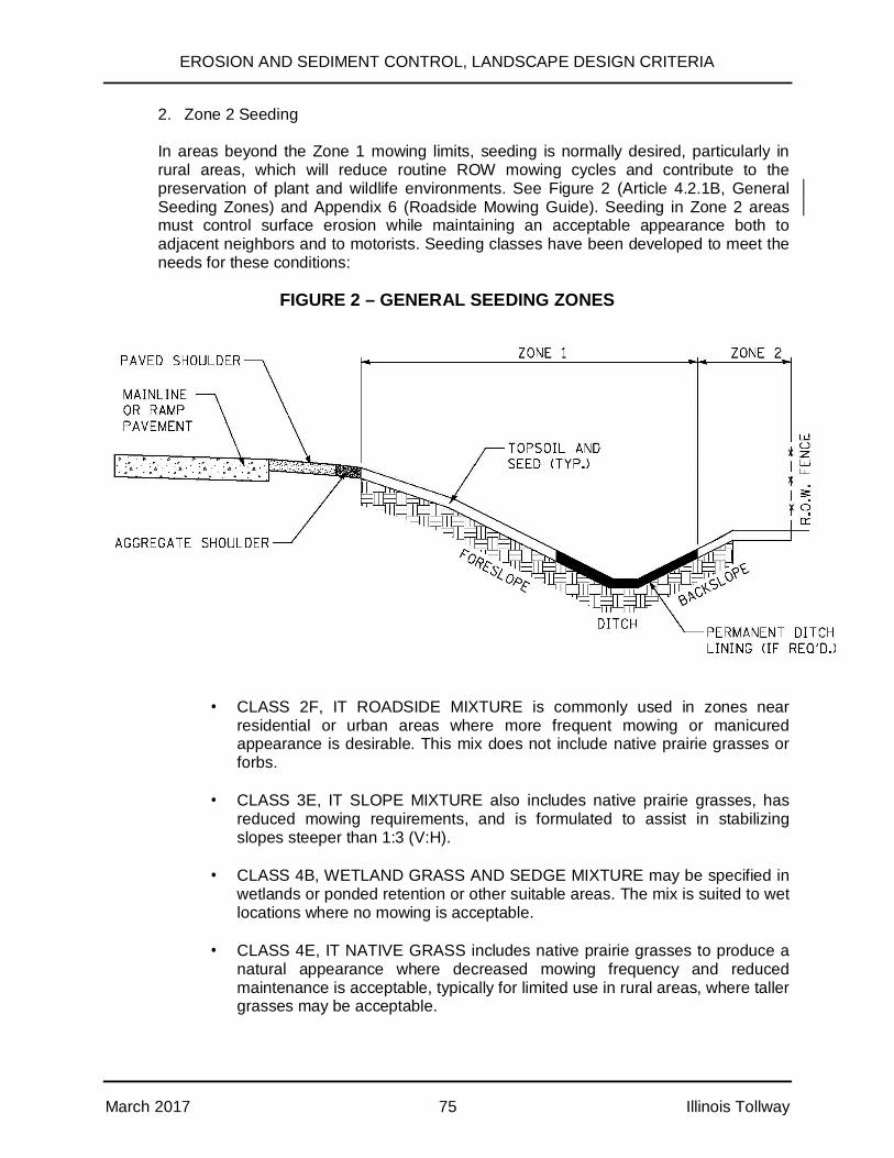
EROSION AND SEDIMENT CONTROL, LANDSCAPE DESIGN CRITERIA
March 2017 75 Illinois Tollway
2. Zone 2 Seeding
In areas beyond the Zone 1 mowing limits, seeding is normally desired, particularly inrural areas, which will reduce routine ROW mowing cycles and contribute to thepreservation of plant and wildlife environments. See Figure 2 (Article 4.2.1B, GeneralSeeding Zones) and Appendix 6 (Roadside Mowing Guide). Seeding in Zone 2 areasmust control surface erosion while maintaining an acceptable appearance both toadjacent neighbors and to motorists. Seeding classes have been developed to meet theneeds for these conditions:
FIGURE 2 – GENERAL SEEDING ZONES
· CLASS 2F, IT ROADSIDE MIXTURE is commonly used in zones nearresidential or urban areas where more frequent mowing or manicuredappearance is desirable. This mix does not include native prairie grasses orforbs.
· CLASS 3E, IT SLOPE MIXTURE also includes native prairie grasses, hasreduced mowing requirements, and is formulated to assist in stabilizingslopes steeper than 1:3 (V:H).
· CLASS 4B, WETLAND GRASS AND SEDGE MIXTURE may be specified inwetlands or ponded retention or other suitable areas. The mix is suited to wetlocations where no mowing is acceptable.
· CLASS 4E, IT NATIVE GRASS includes native prairie grasses to produce anatural appearance where decreased mowing frequency and reducedmaintenance is acceptable, typically for limited use in rural areas, where tallergrasses may be acceptable.
EROSION AND SEDIMENT CONTROL, LANDSCAPE DESIGN CRITERIA
March 2017 76 Illinois Tollway
· CLASS 4F, IT LOW PROFILE NATIVE GRASS also includes native prairiegrasses where decreased mowing frequency and reduced maintenance isacceptable, but where taller grasses are not acceptable. This mixture isgenerally used for most backslope conditions where native grasses arepreferred.
· CLASS 4G, IT POLLINATOR MIXTURE includes low profile native grassesand flowering forbs. This mix is suited to dry, upland areas such as backslopes, basin sides, or embankments with full sun that are to be mowedinfrequently. The forbs within the mix were selected to provide year-roundblooms for pollinators. It is an option for designers with the goal of providinghabitat for pollinators and to display wildflowers for interest at specificlocations. Locations designated for use of this mix shall be reviewed anddiscussed with the Illinois Tollway Landscape Architect prior to use.
This mix should be used as a base; however, site-specific mixes should beused when the following conditions exist:
§ Area to be seeded is greater than 5 acres§ The soil conditions are not uniform§ For wetland mitigation sites
· CLASS 5, FORBS WITH ANNUALS MIXTURE may be specified to be addedwith the class 4E and/or 4F mixtures in areas where wildflowers areacceptable.
· CLASS 5A, LARGE FLOWER NATIVE FORB MIXTURE may be specified tobe added with the class 4E and/or 4F mixtures typically in limited high profileareas where larger, showier flowers are desired. Selective Mowing Stakesmay be needed when adding this mix to assist the maintenance crews bydirecting mowing activities.
· CLASS 5B, WETLAND FORB MIXTURE may be specified in wetlands oroccasionally ponded retention areas. The mix is suited to wet locations and isto be combined with Class 4B where forbs and no mowing is desirable.
Additional seed mixes may be required for detention basins, retention basins, wetlands,restoration areas, or other site specific conditions. These mixes shall be addressedindividually, reviewed with the Illinois Tollway Landscape Architect, and be included in thecontract special provisions.
All seeds shall meet Article 1081.04 of the Standard Specifications requirements.
For seeding in swales, the maximum velocity for seeding is to be determined by IllinoisTollway DDM Table 7.0, Permissible Flow Velocities For Grass Lined Channels.
EROSION AND SEDIMENT CONTROL, LANDSCAPE DESIGN CRITERIA
March 2017 77 Illinois Tollway
C. Bare Earth Seeding
Pay Items:
25000100 - 25000350 – SEEDING, Various ClassesJS250220 - JS250350 – SEEDING, Various Classes
Description and Purpose:
Bare earth seeding will require seed bed preparation prior to applying seed. The area tobe seeded shall be cleared and prepared as detailed in Articles 250.05 and 250.06 ofthe Illinois Tollway Supplemental Specifications.
Application:
· No seeds shall be sown until the seed bed has been approved by the Engineer.
D. Interseeding
Pay Item:
25003110 - INTERSEEDING, Various Classes
Description and Purpose:
Interseeding in areas of existing turf shall be done in conformance with Article 250.06 ofthe Standard Specifications.
Application:
· Where desirable, native grasses may be interseeded into the existing turf in theprocess of converting previously mowed areas to reduced mowing areas. Thisprocedure is used in selected Zone 2 seeding areas only.
· In select reduced mowing areas where added diversity is desired, CLASS 5,FORBS WITH ANNUALS MIXTURE or CLASS 5A, LARGE FLOWER NATIVEFORB may be sowed into existing native turf to highlight or further enhance theappearance of an area. Selective Mowing Stakes may be utilized to delineate thereduced mowing area and assist the maintenance crews by clearly directingfuture mowing activity.
· These grasses and forbs may take several years to establish and are generallyimplemented to reduce mowing, supplement existing turf and provide a naturalmeadow ground cover appearance. Wildflower seeding may need to bereseeded on a regular basis to provide long term benefit.
EROSION AND SEDIMENT CONTROL, LANDSCAPE DESIGN CRITERIA
March 2017 78 Illinois Tollway
E. Fertilizer and Agricultural Ground Limestone Application
Pay Items:
25000400 - NITROGEN FERTILIZER NUTRIENT, POUND25000500 - PHOSPHORUS FERTILIZER NUTRIENT, POUND25000600 - POTASSIUM FERTILIZER NUTRIENT, POUND25000700 - AGRICULTURAL GROUND LIMESTONE, TON
Description and Purpose:
Fertilizer should be specified for newly seeded areas. Agricultural limestone andphosphorus is typically not required for seeding on Illinois Tollway ROW. In the absenceof soil testing, the application rate provided in Article 250.04 should be used.
Application:
Soil testing should be conducted during the initial stages of the design process whereexisting topsoil is to be re-used on the site. The soil tests should be used, along withvisual inspection, to determine areas where existing topsoil is unacceptable for re-use,resulting in the need for removal from the site. The tests may then be used to moreaccurately determine fertilizer application rates to supplement natural fertility levels ofthe re-used topsoil.
When re-use of site topsoil is considered, soil tests shall be taken from the in-placematerial at its natural location. Locations not acceptable for use as topsoil shall beclearly shown on the drawings and/or special provisions for removal prior to stockpiling.The Designer is responsible for initiating and directing soil testing that is to be carried outby a state laboratory, or a recognized commercial laboratory, using approved methods.Soil tests shall include the following:
1. Chemical Analysis
BIOASSAY TESTS shall be provided to determine the persistence of plantdamaging chemical residue and its damage potential. Should the bioassay tests onany samples disclose the presence of chemical activity adverse to acceptable plantgrowth, the material represented by those samples shall be disqualified for use astopsoil.
SOLUBLE SALT TESTS indicating salt content in parts per million (ppm) shall beprovided. If the tests disclose soluble salt concentrations in excess of 1000 ppm, thematerial represented by those samples shall either be disqualified for use as topsoilor a cost effective reclamation process shall be recommended.
PH TESTS shall be provided to measure acidity and alkalinity levels to assist indetermining the availability of nutritional material in the soil, and the consequentability of plants to extract materials from the soil.
PHOSPHORUS, and POTASSIUM TESTS shall be provided to indicate theavailable nutrient levels in the soil.
EROSION AND SEDIMENT CONTROL, LANDSCAPE DESIGN CRITERIA
March 2017 79 Illinois Tollway
2. Mechanical Analysis
PERCENT SAND, SILT, and CLAY shall be provided. Turf grown on different soilsmay respond differently to the same fertilizer. It is therefore important to review andunderstand the soil type.
3. Laboratory Recommendation
Rates for application of nitrogen, phosphorus, potassium, and agricultural groundlimestone or sulfur shall be provided by the testing agency. Nutrients that arealready available to the plants in adequate amounts shall not be added, and the useof phosphorus shall be minimized.
Soil samples shall be collected from a series of sub-sample points equallydistributed across the area to be represented. All sub-samples representing thesample area near the shoulder shall be taken within 10 feet of the shoulder. Thesesoil sub-samples shall be taken to a depth of 6 inches to 8 inches for eachrepresentative area. The sub-samples shall be thoroughly mixed together for eachrepresentative test area prior to testing. A minimum of 3 sub-samples shall begathered for each soil sample area representing approximately 1 acre of in-placetopsoil.
The Designer shall visually review areas such as ramp side slopes and snowdisposal locations which show evidence of heavy erosion, poor turf growth, or saltsaturation as possible locations for topsoil removal. A 6 feet wide strip of topsoilalong the edge of the pavement shall be removed and disposed of on mainline andramp widening improvements. This is in addition to soil in other areas identified forremoval by visual inspection and/or topsoil testing.
Additional specifications for fertilizer application use on existing trees and sod canbe found in:
· Care of Existing Plant Material, Section 201 of the Standard Specifications
· Ground Preparation for Sodding, Section 252 of the Standard Specifications
F. Seeding and Sodding Times
Description and Purpose:
Article 250.07 (Note 7) of the Illinois Tollway Supplemental Specifications and Article252.04 of the Standard Specifications provide seeding and sodding dates. The Designershall carefully consider the seasonal planting limitations for each seeding and soddingitem and coordinate their timing into the construction schedule.
G. Selective Mowing Stakes
Pay Item:
25000775 – SELECTIVE MOWING STAKES, EACH

EROSION AND SEDIMENT CONTROL, LANDSCAPE DESIGN CRITERIA
March 2017 80 Illinois Tollway
Description and Purpose:
Selective mowing stakes may be used in seeding to assist in delineating reduced or no-mow areas, in compliance with Article 250.08 of the Standard Specifications. Selectivemowing stakes are installed to assist the maintenance crews by clearly directing futuremowing activity at approved locations.
H. Mulch, Erosion Control Blankets
Pay Items:
25100105 - 25100135 – MULCH, Various Methods25100630 - 25100900 – Various Erosion Control BlanketsJI251010 - EROSION CONTROL BLANKET, BIODEGRADABLE NETTINGJI251015 - HEAVY DUTY EROSION CONTROL BLANKET, BIODEGRADABLE
NETTING
Description and Purpose:
Mulch is a protective covering of organic material typically used with permanent seeding,and is laid over the soil to reduced erosion, retain moisture, retain seed, and protectplantings.
These items consist of furnishing, transporting, and placing straw and/or wood fibermulch on seeded areas (Article 251.03 of the Standard Specifications and IllinoisTollway Supplemental Specifications). Material shall be in conformance with Article1081.06 of the Standard Specifications. Refer to IDOT’s Bureau of Design andEnvironmental Manual, Sediment Control Practices Reference Table (Figure 41-3.C) fortreatments to be considered and recommended.
Article 251.04 of the Standard Specifications provides guidance on placing erosioncontrol blankets on seeded areas. Erosion control blankets are most commonly usedwith permanent seeding. Limited use may also be considered for temporary erosioncontrol on very steep slopes or other extreme conditions. Materials shall be inconformance with Article 1081.10 of the Standard Specifications.
These items can be used in conjunction with Section 250 (Seeding), Section 253(Planting Woody Material), Section 254 (Planting Perennial Plants), and subject toArticle 1081.06 requirements.
Application:
Mulch, Straw, Fiber, Compost
· Use with permanent seeding on prepared slopes up to 1:10 (V:H) unless erosioncontrol blanket is provided; and
· Provide erosion control blanket when slopes meet or exceed 1:10 (V:H).
· Provide sod or erosion control blanket in swales.

EROSION AND SEDIMENT CONTROL, LANDSCAPE DESIGN CRITERIA
March 2017 81 Illinois Tollway
· Unless dictated by the necessities of the project or other reasons where, in theDesigner’s judgment, one procedure is preferable, the Contractor should beallowed to use any or all of these procedures interchangeably.
1. Mulch Method 1
· Mulch Method 1 comprises the application of loose straw mulch by handor machine.
· Use in flat areas where wind displacement will not carry mulch onto theroadway or off Illinois Tollway property.
· Apply at a rate of 2 tons/acre.
2. Mulch Method 2
· Mulch Method 2 comprises the application and stabilization of strawmulch by mechanical or chemical procedures.
· Procedure 2 comprises the placement of straw mulch by blower, followedby an overspray of hydraulic mulch. This procedure is particularly suitedto confined areas where access by a tractor might be difficult and onareas which have been hydroseeded.
· Apply straw mulch at the same rate as Method 1.
· Apply hydraulic mulch at a rate of 750 pounds/acre and water at a rate of1,000 gallons/acre.
· Procedure 3 comprises the application of chemical stabilizer to blownstraw mulch. The chemical binder and application rate shall be acceptedby the Engineer prior to use to ensure the product is environmentally safeand acceptable.
· Do not use gypsum, emulsified asphalt, or plaster-like binders.
3. Mulch Method 3
· Mulch Method 3 is not used individually on the Illinois Tollway.
4. Mulch Method 4
· This method consists of applying compost combined with a performanceadditive designed to bind/stabilize the compost.
· The compost/performance additive mixture shall be applied to the surfaceof the slope to a depth of 2 inches using a pneumatic blower.
EROSION AND SEDIMENT CONTROL, LANDSCAPE DESIGN CRITERIA
March 2017 82 Illinois Tollway
· Mulch Method 4 can only be used if approved by the Illinois TollwayLandscape Architect.
Erosion Control Blanket:
· These items are typically more effective than mulch alone and consist offurnishing and installing erosion control blankets over prepared permanentseeding beds as shown on the plans or as directed by the Engineer.
· Because of continuing new technology in erosion control, the Designer isencouraged to explore new methods and materials beyond those shown in theStandard Specifications for erosion control and turf reinforcement. The Designershall be familiar with such products, evaluate and recommend their use whenappropriate. For example, if there is a slope failure as a result of regularsubsurface drainage, other methods shall be employed to correct the problemprior to application of erosion blanket surface treatments or when innovativemethods and/or materials may be beneficial to prevent scour at drain outlets.
· Erosion blankets are typically used in conjunction with permanent seeding, asper Section 250 of the Illinois Tollway Supplemental Specifications and Article1081.04 of the Standard Specifications.
1. Erosion Control Blanket, Biodegradable Netting
· This item is a single net Rolled Erosion Control Product (Erosion Blanket)intended for short term use on shallow slopes. The netting is intended tobiodegrade in 90 days. This product is described in Articles 1081.10(a)and (b) of the Standard Specifications.
· Excelsior Blanket or Knitted Straw Mat can be used interchangeably.
· To be used in conjunction with permanent seeding, Section 250 of theIllinois Tollway Supplemental Specifications.
· Use in swales where the hydraulic shear is less than 2.1 pounds persquare foot.
· To be used on all slopes within a 30 feet wide strip adjacent to theroadway and ramp pavements where wind and debris create a difficultenvironment for seed germination.
· May be used with Temporary Ground Cover, Article 280.04(f) of theStandard Specifications, for temporary erosion control in swales with amaximum velocity of 6 feet per second.
2. Heavy Duty Erosion Control Blanket, Biodegradable Netting
· This item is a double net Rolled Erosion Control Product (ErosionBlanket) intended for short term use on steeper slopes. The bottom
EROSION AND SEDIMENT CONTROL, LANDSCAPE DESIGN CRITERIA
March 2017 83 Illinois Tollway
netting is intended to remain in service as turf reinforcement. Thisproduct is described in Article 1081.10(c) of the Standard Specifications.
· To be used as a permanent, non-degradable liner primarily to stabilizechannel configurations while permanent vegetation is establishing. Thisblanket works best when drainage can be diverted until turf is established.
· To be used as permanent lining in swales where the hydraulic shear isbetween 2.1 and 6.0 pounds per square foot.
· To be used with permanent seeding of specified channels or ditches withvelocities between 4 feet and 6 feet per second.
· When velocities exceed 6 feet per second, line channel or ditch perIllinois Tollway DDM, Section 7.0 – Ditch and Channel Design.
· May be used for temporary erosion control in swales with velocitiesbetween 6 and 10 feet per second.
I. Sodding
Pay Items:
25200100 – SODDING25200110 – SODDING, SALT TOLERANT
Description and Purpose:
In general, sodding is to be used in a limited basis at specifically designated areas, suchas toll plazas, applicable ditches, maintenance buildings, oasis, or other supportcomplexes. Sodding (salt tolerant) shall be used in designated areas within 30 feet fromthe edge of pavement. Salt tolerant sod may also be considered for use in drainageditches where flow velocities do not exceed 4 feet per second and slope is no more than10%. A channel lining shall be required where the flow velocity exceeds 4 feet persecond and ditch slope exceeds 10%. For additional details see Section 252 of theStandard Specifications and the Illinois Tollway DDM, Section 7.0 Ditch and ChannelDesign. Sodding shall be done in conformance with Article 1081.03 of the StandardSpecifications.
J. Perennial PlugsPay items:
JT250400 – Mesic Bioswale Plug MixJT254010, JT254015 – Bioswale PlugsJT254100 – Wetland Plugs
Description and Purpose:
Native plugs may be used on a limited basis when standing water prevents the use ofseed. In instances where shallow standing water is the norm within wet bottomed
EROSION AND SEDIMENT CONTROL, LANDSCAPE DESIGN CRITERIA
March 2017 84 Illinois Tollway
retention/detention ponds, plugs may be considered in place of seed. In all otherinstances, seed and erosion control blanket will be used in conformance with Article4.2.1 of this manual. For additional details, see Section 254 of the StandardSpecifications. The planting of plugs shall be done in conformance with Article 1081.02of the Standard Specifications.
Application:
· If contract completion date is later than October 1st, plugs shall not be utilizedunless written authorization from the Illinois Tollway Landscape Architect.
· Plugs may be used in project specific inclusion of bioswales or wetlandmitigation.
K. Watering and Supplemental Watering
Pay Item:
25200200 – SUPPLEMENTAL WATERING
Description and Purpose:
Supplemental watering may be required for sod during periods of heat or drought, perArticle 252.09 (Sodding) of the Standard Specifications.
Application:
· During the period of establishment, watering is typically incidental for woodyplants (Article 253.15 of the Standard Specifications) and Perennial Plants(Article 254.09 of the Standard Specifications), and is not consideredsupplemental.
· If woody plant supplemental watering and seeding supplemental watering isneeded, it shall be provided in the Special Provisions for each contract.
· Supplemental Watering is used in conjunction with sodding and is most criticalduring the initial 60 day establishment period. This item is typically used tosupplement the contractors required watering during the first 30 days in the eventof hot or dry periods, and/or for watering needed beyond the first 30 day growingperiod. This item is not required for seeding.
L. Herbicide and Weed Control
Description and Purpose:
Weed control should be used for weed management opportunities and may be neededeither before planting or during the period of establishment. Weeding for woody plantsshall be done during the period of establishment per Article 253.15 of the StandardSpecifications and at the end of the period of establishment for perennial beds per
EROSION AND SEDIMENT CONTROL, LANDSCAPE DESIGN CRITERIA
March 2017 85 Illinois Tollway
Article 254.09 of the Standard Specifications. Additionally, weed control may be used forexisting areas or as required at the direction of the Engineer.
Weed control may be accomplished through the use of Weed Barrier Fabric, as specifiedin Article 1081.14; mulch for woody plants, as specified in Article 253.11; or mulch forperennial beds, as specified in Article 254.07 (all of the Standard Specifications).
M. Filter Fabric
Pay Item:
28200200 - FILTER FABRIC, SQUARE YARD
Description and Purpose:
Filter fabric is used to provide a separation between fine grained and open gradedmaterials in order to prevent intermingling of the materials. For example, it may be usedto separate planting mix from drain stone, drain stone from subgrade, or planting mixfrom coarse subgrade. Filter fabrics shall be in accordance with Article 1080.03 of theStandard Specifications.
4.2.2 Planting, Removal, and Care
Per Sections 253 and 254 of the Standard Specifications, all placements of plantings along theroadside shall comply with Illinois Tollway and AASHTO safety recommendations, includingthose for clear zones and distance from signage, and shall follow the overall guidelines to blendthe facility into the surrounding areas.
When trees must be removed, opportunities for providing replacement shall be pursued (SeeAppendix 9). The addition of vegetation can be reviewed once all existing desirable vegetationhas been protected.
The adjacent land use and topography shall provide direction for the intensity of the planting.Rural areas may require little or no planting, while more urban sites should be more heavilyplanted in an effort to blend into the adjacent community. A natural and sustainable landscapeshall be the basis for all roadside design.
A. Clearing, Tree Removal and Protection, Care and Repair of Existing PlantMaterial
Pay Items:
20100110 through 20101700
Description and Purpose:
Clearing shall consist of removal and disposal of obstructions, logs, and vegetationaccording to Article 201.01 of the Standard Specifications. Clearing shall be used whenvegetation interferes with construction activities, when dead or diseased trees arepresent in the work zone, or as directed by the Illinois Tollway, except when specified inthe plans that the tree should be protected. The Designer and CM shall review and
EROSION AND SEDIMENT CONTROL, LANDSCAPE DESIGN CRITERIA
March 2017 86 Illinois Tollway
inventory the existing vegetation and complete site inspections to save or protectexisting vegetation of value, whenever possible.
Application:
· Care of existing plant material consists of pruning, fertilizing, and watering ofexisting vegetation to remain, and shall be done in accordance with Articles201.05 – 201.06 of the Standard Specifications. Repair or replacement ofexisting plant material consists of restoring plants damaged by the Contractor toits original condition, per Article 201.07 of the Standard Specifications. The needfor protection or repair of existing plant material will be identified by the Designerduring the design phase. These determinations will be made based on fieldinspections; project specific conditions; plant size, type, condition; andprofessional judgment. Plant material damaged by the Contractor shall berepaired at no additional cost to the Illinois Tollway.
· The need for the repair or replacement of existing plant material shall beevaluated during design by the DSE’s Landscape Architect.
B. Planting Woody Plants and Perennial Plants
Pay Items:
A2C00G03 through B2013916 – TREES, VariousC2C00124 through C3006024 – SHRUBS, VariousD20C00412 through D2015401 – EVERGREENS, VariousE20010G1 through E20330Q1 – VINES, VariousF2001072 through H20040Y2 – SEEDLINGS, VariousK0012970 through K0013110 – PERENNIALS, VARIOUS
Description and Purpose:
Landscape within the Illinois Tollway ROW accomplishes multiple purposes, includingpermanent erosion control, aesthetics, and visual screening of adjacent residential orcommercial properties. It is important to design this border to be aesthetically appealingand to blend in with surroundings, but it is also important to provide a landscape that isfunctional and easily maintained. Maintenance activities, such as mowing, can beminimized through the use of woody plants (trees, shrubs, evergreens, vines) orperennial herbaceous plants (ornamental plants or native plants, including wetland,woodland, or prairie plants). Plants shall be chosen based on general landscape design,location, growing requirements, maintenance requirements, and aesthetics. Materials forplanting of woody and perennial plants shall be done in conformance with Section 1081of the Standard Specifications.
Application:
· The Illinois Tollway may initiate adjacent landowner or municipal outreach. Theadjacent entities may provide input for the Illinois Tollway to consider, and mayresult in cost-participation by the local entity to increase quality or quantity of thelandscape plan.
EROSION AND SEDIMENT CONTROL, LANDSCAPE DESIGN CRITERIA
March 2017 87 Illinois Tollway
· All placement of plantings along the roadside shall comply with Illinois Tollwayand AASHTO safety recommendations, including clear zones and distance fromsignage, and shall follow overall guidelines to blend the facility into thesurrounding areas.
· When trees must be removed, opportunities for providing replacements shall bepursued (See Appendix 9, Preservation, Removal and Replacement of Trees).The addition of vegetation can be reviewed once all existing desirable vegetationhas been protected.
· The adjacent land-use and topography should provide direction for the intensityof the planting. Rural areas may require little or no planting while more urbansites should be more heavily planted in an effort to blend into the adjacentcommunity. A natural effect should be the basis for all roadside design.
· The Landscape DSE shall also address maintenance, such as mowingexpectations. Mowing and Turf Maintenance activities should be minimized inareas of woody plants (trees, shrubs, evergreens, vines) or perennial herbaceousplants (ornamental plants or native plants, including wetland, woodland, or prairieplants). Plants shall be chosen based on general landscape design, location,growing requirements, maintenance requirements, and aesthetics.
4.2.3 Protection of Existing Resources
Certain existing landscape features, whether manmade or natural, shall be protected through aprocess of identification; enhancement, restoration, or preservation; avoidance; or incorporationinto the design of the highway improvement. A variety of techniques may be employed toprotect identified resources, including both temporary and permanent measures, as appropriate.The appropriate technique shall be determined during the design concept phase. Consider thefollowing when protecting existing features.
A. Review Previous Commitments
Review commitments in environmental documents, ESIS, tree surveys, wetlandreports, public hearing records, and other project documents for areas requiringattention or protection during project development and implementation.
B. Statute Protection
Determine which features of the project area are protected by statute. These mayinclude wetlands, endangered species, nature preserves, natural areas, and culturalsites.
C. Cultural Environment
Establish the project’s setting or cultural environment. Determine if the project is in arural, urban, or a transitional area. The design shall be influenced by the cultural andphysical environment adjacent to it. Existing features shall be protected whenpossible.
EROSION AND SEDIMENT CONTROL, LANDSCAPE DESIGN CRITERIA
March 2017 88 Illinois Tollway
4.2.4 Grading and Alignment
The portion of the design process concerning alignment and grading offers the best opportunityto fit the highway into the landscape, thereby avoiding unnecessary environmental impacts andyielding a functional and aesthetically pleasing form. The basic guidelines for grading andalignment are included in the AASHTO-“Guide for Transportation Landscape and EnvironmentalDesign”. In addition, consider the following:
A. Environmental Commitments
During Master Planning, ensure that all environmental commitments, including theEVA and tree inventories, are reviewed and noted so that these issues canappropriately influence alignment and grading decisions. These commitments willalso serve as controls during Design Phase plan preparation.
B. Surrounding Landscape
Give consideration to the surrounding landscape and the best application of site cutand fill for functional use and balancing. Blend the alignment and grading to fit theexisting topography with minimal visual or physical disruption. Where appropriate,screen unsightly views of industrial areas, junkyards, etc. Vegetative screens shouldalso be provided as visual buffers for residential development.
C. Clearing and Construction Limits
Carefully plan and define the establishment of clearing and construction limits.Consider both existing landscape features and critical areas.
D. Plant Survival
Consider the survival potential of both existing plantings to be preserved andproposed plantings at the time that grading decisions are made. Existing plantingsare vulnerable when there is the potential for disturbance to root zones or drainagepatterns. This is especially critical in confined areas where landscape features suchas screening are proposed.
4.2.5 Erosion Control
The measures incorporated in the Landscape Plans shall permanently protect the site fromerosion and sediment damage to adjacent sites.
Every effort shall be made to schedule the permanent erosion control to be completed as earlyas practical, to minimize the cost of the temporary control measures.
All projects shall comply with current provisions of the EPA’s “Clean Water Act” (see IllinoisTollway DDM). Erosion control plans shall clearly describe the location, type of controls, andscheduling to be implemented in each stage of construction. Special resources, such aswetlands, shall be clearly identified along with erosion protection measures. Specific projectneeds, problem areas, and erosion control philosophy shall be identified and discussed at thePreconstruction Erosion and Sediment Control Meeting. The Preconstruction Erosion andSediment Control Meeting also includes a field review.
EROSION AND SEDIMENT CONTROL, LANDSCAPE DESIGN CRITERIA
March 2017 89 Illinois Tollway
4.2.6 Drainage
Design of the highway drainage system shall be part of, and not separate from, the naturalhydrology of the environment. Consider the environmental impacts of drainage, stormwatermanagement, detention or retention basin design shapes, and the impact that water retentionand/or soil saturation will have on existing or proposed plant material.
See the Illinois Tollway DDM for more detailed guidance.
4.2.7 Visual Quality
Encouraging a visual change that will improve or enhance the surrounding landscape ensures aproject’s visual quality. Define the visual environment by identifying key views, analyzingresources, depicting the project’s proposed appearance, and assessing its visual impacts.Manmade features such as buildings, bridges, retaining walls, sound walls, and other structuresshall also be assessed during the project design and integrated successfully into the Illinoisnatural landscape.
To support the reduction of maintenance and enhance visual quality in a project, evaluate theproject’s relationship with regards to the following:
· natural landscape elements,
· topographical ,physical characteristics, and functional use of cut and fill,
· ecological influences,
· residential areas and their character,
· historical features,
· visual and psychological values,
· existing land uses, and
· existing and proposed project profile and structures.
4.2.8 Safety
Safety shall be the highest functional goal of every Illinois Tollway design, and all landscape andenvironmentally based design principles shall be compatible with such criteria.
During design, consider the following:
· soil erosion/pollution control;
· the location, size, and height (mature size, height) of plantings in relation to sightdistance, drainage, and clear zones;

EROSION AND SEDIMENT CONTROL, LANDSCAPE DESIGN CRITERIA
March 2017 90 Illinois Tollway
· pedestrian safety in areas such as oasis areas, toll plazas, and bikeways;
· reduction of headlight glare;
· directional and feature delineation or screening;
· snow drifting and environmental conditions control; and
· sound abatement.
4.2.9 Historical Influences
Historical influences may affect the project by way of a nearby destination, an adjacent feature,or in some cases, as a part of the roadway or its appurtenances. Pay particular attention to suchinfluences and prepare the project design to be compatible or to harmonize with them. Historicalmarkers, structures, districts, and bridges all may influence the design of a project. Requiredavoidance of, or mitigation of impacts to, historical resources are usually identified in earlyproject coordination, but the Landscape DSE shall be alert for any unidentified items. Specialconsideration may need to be given to landscape treatment within designated National RegisterHistoric Districts.
4.2.10 Planting Treatments
A. Treatment of Mainline ROW
1. Roadside plantings under normal conditions are viewed at high speeds. Theamount, spacing, and size of planting shall be sufficient to produce a groupingthat will be recognized by the passing motorists. At high speeds, the angle of adriver’s vision narrows and distant views are held for a longer time. Therefore,typically, lineal and more extensive swaths of planting masses shall be usedalong mainline locations with decreasing plant bed size near or at plazas.
2. There should be an overall naturalistic theme for the landscape design, withgroups of primarily native trees following free form lines, unless a specificlocalized design intent requires a more formal planting. Shrub planting beds shallfollow contour lines in defined, intentional shapes. Shrubs shall be spaced closeenough so plants grow together, reducing future maintenance.
3. Maintenance shall be a prime consideration of the landscape design. Integrationof tree, shrub, and turf areas shall be designed to minimize mowing aroundindividual plants. This may be achieved by using architectural mow lines tocreate areas where mowing is reduced and by planting predominantly in naturalgroupings. Trees shall be located within no mowing zones or reduced mow areaswhenever possible. Selective Mowing Stakes shall be considered to delineateareas that do not require mowing.
4. All tree and shrub plantings shall be kept out of the clear zone as defined inAASHTO - Roadside Design Guide. The clear zone along the mainline variesbased on the steepness of the slopes and design speed. Refer to the IllinoisTollway’s Traffic Barrier Guidelines for more information. Typically, tree and
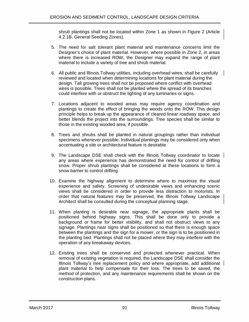
EROSION AND SEDIMENT CONTROL, LANDSCAPE DESIGN CRITERIA
March 2017 91 Illinois Tollway
shrub plantings shall not be located within Zone 1 as shown in Figure 2 (Article4.2.1B, General Seeding Zones).
5. The need for salt tolerant plant material and maintenance concerns limit theDesigner’s choice of plant material. However, where possible in Zone 2, in areaswhere there is increased ROW, the Designer may expand the range of plantmaterial to include a variety of tree and shrub material.
6. All public and Illinois Tollway utilities, including overhead wires, shall be carefullyreviewed and located when determining locations for plant material during thedesign. Tall growing trees shall not be proposed where conflict with overheadwires is possible. Trees shall not be planted where the spread of its branchescould interfere with or obstruct the lighting of any luminaries or signs.
7. Locations adjacent to wooded areas may require agency coordination andplantings to create the effect of bringing the woods onto the ROW. This designprinciple helps to break up the appearance of cleared linear roadway space, andbetter blends the project into the surroundings. Tree species shall be similar tothose in the existing wooded area, if possible.
8. Trees and shrubs shall be planted in natural groupings rather than individualspecimens whenever possible. Individual plantings may be considered only whenaccentuating a site or architectural feature is desirable.
9. The Landscape DSE shall check with the Illinois Tollway coordinator to locateany areas where experience has demonstrated the need for control of driftingsnow. Proper shrub plantings shall be considered at these locations to form asnow barrier to control drifting.
10. Examine the highway alignment to determine where to maximize the visualexperience and safety. Screening of undesirable views and enhancing scenicviews shall be considered in order to provide less distraction to motorists. Inorder that natural features may be preserved, the Illinois Tollway LandscapeArchitect shall be consulted during the conceptual planning stage.
11. When planting is desirable near signage, the appropriate plants shall bepositioned behind highway signs. This shall be done only to provide abackground or frame for better visibility, and shall not obstruct views to anysignage. Plantings near signs shall be positioned so that there is enough spacebetween the plantings and the sign for a mower, or the sign is to be positioned inthe planting bed. Plantings shall not be placed where they may interfere with theoperation of any breakaway devices.
12. Existing trees shall be conserved and protected whenever practical. Whenremoval of existing vegetation is required, the Landscape DSE shall consider theIllinois Tollway’s tree replacement policy and where appropriate, add additionalplant material to help compensate for their loss. The trees to be saved, themethod of protection, and any maintenance requirements shall be shown on theconstruction plans.

EROSION AND SEDIMENT CONTROL, LANDSCAPE DESIGN CRITERIA
March 2017 92 Illinois Tollway
13. The design shall take into consideration salt spray and drifting from winterplowing operations. Assume winter winds will be predominantly from the north,northwest, and west. Salt drifting can carry up to approximately 150 feet, withheavy concentrations of salt spray up to 30 feet from the edge of pavement. Thedesign shall address ramps, plazas, and other areas where concentrations of saltsaturated surface runoff may affect adjacent turf.
14. Large planting projects may include a small percentage of fast growing trees toprovide the immediate benefit of large plant material while slower growing plantsmature.
15. Subsurface drainage on cut slopes that interferes with soil sediment control orproper vegetation establishment shall be identified and evaluated for repair.
B. Treatment of Drainage Channels and Ditches
Ditch bottom erosion, and the depositing of sediment from the erosion of side slopes,are prevailing problems with ditches. Erosion control treatment of these slopes shallbe handled in accordance with Article 3.2.1 of this manual, to ensure minimumsedimentation of drainage ways during turf establishment.
A minimum of 0.3% longitudinal slope shall be maintained in any channel and ditchbottom where positive drainage is expected. Flatter minimum grades will producepockets of standing water and cattail growth, and may increase the need for futuremaintenance. For roadside ditches with a longitudinal slope less than 0.3% (i.e., dueto some special local conditions), a ditch lining shall be provided. Consult the IllinoisTollway DDM for details.
The ditch cross section shall typically be trapezoidal in shape and maintain a 6 footwide bottom whenever possible. (Per the Illinois Tollway DDM, ditches shall maintaina minimum 4 foot wide bottom.) The erosion control measures be salt tolerantsodding, erosion blanket lining with salt tolerant seed, or open cell articulatedconcrete block mats, depending on specific slope and hydraulic conditions. Any otheravailable erosion control products existing on the market can be used if costeffective, upon the acceptance by the Illinois Tollway PM.
See Article 4.2.1, Paragraph H for applications of Erosion Blankets. When seeding isused in ditch bottoms, it is best to restrict flowing water until turf is established. Whensodding is used, water velocities up to 4 feet per second may remain without beingrestricted during establishment. Properly placed sod is normally the preferred coverin swales because there is no time lag between installation and the time when thechannel is protected by vegetation. Sod also offers more flexibility in the timing ofinstallation than seeding. Channel lining shall be required where the designdischarge velocity exceeds the scour velocity of the soil. See Illinois Tollway DDMSection 7.0 – Ditch and Channel Design Section for additional information.
Trees or shrubs shall not be planted in or near drainage ways where their presencewould interfere with the flow of water or access to drainage structures.
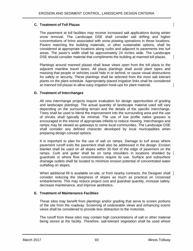
EROSION AND SEDIMENT CONTROL, LANDSCAPE DESIGN CRITERIA
March 2017 93 Illinois Tollway
C. Treatment of Toll Plazas
The pavement at toll facilities may receive increased salt applications during wintersnow removal. The Landscape DSE shall consider salt drifting and higherconcentrations of brine associated with snow plowing operations in these locations.Pavers matching the building materials, or other sustainable options, shall beconsidered at appropriate locations along curbs and adjacent to pavements into turfareas. The paver’s width shall be approximately 24 inches wide. The LandscapeDSE should consider material that compliments the building at manned toll plazas.
Plantings around manned plazas shall leave views open from the toll plaza to theadjacent mainline travel lanes. All plaza plantings shall avoid plant types andmassing that people or vehicles could hide in or behind, or cause visual obstructionsfor safety or security. These plantings shall be selected from the most salt tolerantplants on the plant schedule. Appropriately placed irrigation links shall be consideredat manned toll plazas to allow easy irrigation hook-ups for plant material.
D. Treatment of Interchanges
All new interchange projects require evaluation for design opportunities of gradingand landscape plantings. The actual quantity of landscape material used will varydepending on the surrounding terrain and the details of the specific interchange.Trees shall be used to blend the improvement into the surrounding area and the useof shrubs shall typically be minimal. The use of low profile native grasses isencouraged in the interior of appropriate infields to reduce mowing. Interchanges andramps may be viewed as gateways to some local communities. The Landscape DSEshall consider any defined character developed by local municipalities whenpreparing design concept options.
It is important to plan for the use of salt on ramps. Damage to turf areas wherepavement runoff exits the pavement shall also be addressed in the design. Erosionblanket shall be used on all slopes within 30 feet of the edge of pavement on theramps. Curb and gutter shall be on ramp shoulders in locations shielded byguardrails or where flow concentrations require its use. Surface and subsurfacedrainage outlets shall be located to minimize erosion potential of concentrated wateroutfalling on slopes.
When additional fill is available on-site, or from nearby contracts, the Designer shallconsider reducing the steepness of slopes as much as practical on crossroadembankments. This may reduce project cost and guardrail quantity, increase safety,decrease maintenance, and improve aesthetics.
E. Treatment of Maintenance Facilities
These sites may benefit from plantings and/or grading that serve to screen portionsof the site from the roadway. Screening of undesirable views and enhancing scenicviews shall be considered to provide less distraction to the motorists.
The runoff from these sites may contain high concentrations of salt or other materialbeing stored at the facility. Therefore, salt-tolerant vegetation shall be used where
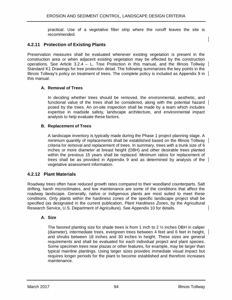
EROSION AND SEDIMENT CONTROL, LANDSCAPE DESIGN CRITERIA
March 2017 94 Illinois Tollway
practical. Use of a vegetative filter strip where the runoff leaves the site isrecommended.
4.2.11 Protection of Existing Plants
Preservation measures shall be evaluated whenever existing vegetation is present in theconstruction area or when adjacent existing vegetation may be effected by the constructionoperations. See Article 3.2.4 – L. Tree Protection in this manual, and the Illinois TollwayStandard K1 Drawings for tree protection detail. The following summarizes the key points in theIllinois Tollway’s policy on treatment of trees. The complete policy is included as Appendix 9 inthis manual.
A. Removal of Trees
In deciding whether trees should be removed, the environmental, aesthetic, andfunctional value of the trees shall be considered, along with the potential hazardposed by the trees. An on-site inspection shall be made by a team which includesexpertise in roadside safety, landscape architecture, and environmental impactanalysis to help evaluate these factors.
B. Replacement of Trees
A landscape inventory is typically made during the Phase 1 project planning stage. Aminimum quantity of replacements shall be established based on the Illinois Tollwaycriteria for removal and replacement of trees. In summary, trees with a trunk size of 6inches or more diameter at breast height (DBH) and other desirable trees plantedwithin the previous 15 years shall be replaced. Minimum ratios for replacement oftrees shall be as provided in Appendix 9 and as determined by analysis of thevegetative assessment information.
4.2.12 Plant Materials
Roadway trees often have reduced growth rates compared to their woodland counterparts. Saltdrifting, harsh microclimates, and low maintenance are some of the conditions that affect theroadway landscape. Generally, native or indigenous plants are most suited to meet theseconditions. Only plants within the hardiness zones of the specific landscape project shall bespecified (as designated in the current publication, Plant Hardiness Zones, by the AgriculturalResearch Service, U.S. Department of Agriculture). See Appendix 10 for details.
A. Size
The favored planting size for shade trees is from 1 inch to 2 ½ inches DBH in caliper(diameter), intermediate trees, evergreen trees between 4 feet and 6 feet in height,and shrubs between 18 inches and 30 inches in height. These sizes are generalrequirements and shall be evaluated for each individual project and plant species.Some specimen trees near plazas or other features, for example, may be larger thantypical mainline plantings. Using larger sizes provides immediate visual impact butrequires longer periods for the plant to become established and therefore increasesmaintenance.

EROSION AND SEDIMENT CONTROL, LANDSCAPE DESIGN CRITERIA
March 2017 95 Illinois Tollway
B. Root
All deciduous trees larger than 1 inch DBH in caliper or 4 feet in height shall bespecified as “balled and burlapped root type”. All evergreen trees shall be specifiedas “balled and burlapped” root type. Shrubs shall be specified as either “balled andburlapped” or “container grown”. Bare root material may be used for smaller plantmaterial but shall be approved by the Illinois Tollway’s Landscape Architect prior tospecifying.
C. Plans and Legend
When the scope of work includes the planting of trees and shrubs as part of thegeneral roadway improvement plans, a separate Plant Materials List shall beincluded in the plans in addition to that provided in the Summary of Quantities (SeeTable 3). If conditions prevent the planting work from being performed concurrently,the landscape plans shall be able to be removed and function independently.

EROSION AND SEDIMENT CONTROL, LANDSCAPE DESIGN CRITERIA
March 2017 96 Illinois Tollway
Table 3Landscape Materials List
Pay Item Description Unit Quantity
RecordQuantity Comments
20101400 Nitrogen Fertilizer Nutrient Pound 300 30 pound/acre
20101600 Potassium Fertilizer Nutrient Pound 1800 90 pound/acre
25200110 Sodding (Salt Tolerant) SY YD 8,500 No fertilizer
JIA20011
Tree, Gleditsia TriacanthosInermis Skyline (SkylineThornless Common HoneyLocust), 1-1/2" Caliper,Balled and Burlapped
Each 36 Specimen qual.B&B root
JIA20020Tree, Quercus Macrocarpa(Bur Oak), 1-1/2" Caliper Each 50 Specimen qual.
B&B root
JIC20010
Shrub, Lonicera TataricaArnold Red, (Arnold RedTatarian Honeysuckle), 6"Height
Each 32 Specimen qual.B&B root
JIC20015Shrub, CephalanthusOccidentalis (Button Bush)Container Grown, 3-Gallon
Each 160 Full specimen
JI251010 Erosion Control Blanket,Biodegradable Netting SQ YD 104,54
4
ObservestaplingRequirements
JS250220 Seeding, Class 2E Acre 21.6 Salt tolerant
JT253020 Summer Watering Unit 102
K0026710 Tree Care Mulch LumpSum 1
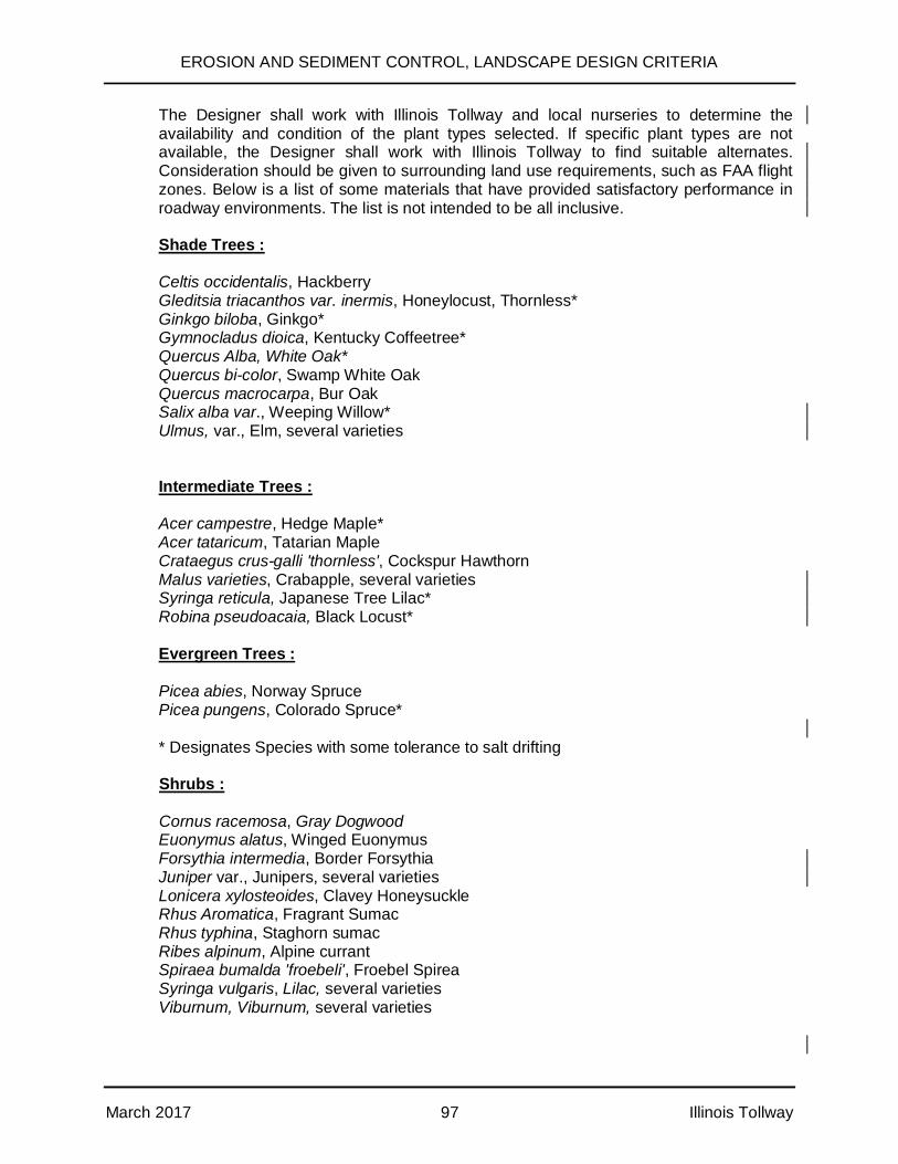
EROSION AND SEDIMENT CONTROL, LANDSCAPE DESIGN CRITERIA
March 2017 97 Illinois Tollway
The Designer shall work with Illinois Tollway and local nurseries to determine theavailability and condition of the plant types selected. If specific plant types are notavailable, the Designer shall work with Illinois Tollway to find suitable alternates.Consideration should be given to surrounding land use requirements, such as FAA flightzones. Below is a list of some materials that have provided satisfactory performance inroadway environments. The list is not intended to be all inclusive.
Shade Trees :
Celtis occidentalis, HackberryGleditsia triacanthos var. inermis, Honeylocust, Thornless*Ginkgo biloba, Ginkgo*Gymnocladus dioica, Kentucky Coffeetree*Quercus Alba, White Oak*Quercus bi-color, Swamp White OakQuercus macrocarpa, Bur OakSalix alba var., Weeping Willow*Ulmus, var., Elm, several varieties
Intermediate Trees :
Acer campestre, Hedge Maple*Acer tataricum, Tatarian MapleCrataegus crus-galli 'thornless', Cockspur HawthornMalus varieties, Crabapple, several varietiesSyringa reticula, Japanese Tree Lilac*Robina pseudoacaia, Black Locust*
Evergreen Trees :
Picea abies, Norway SprucePicea pungens, Colorado Spruce*
* Designates Species with some tolerance to salt drifting
Shrubs :
Cornus racemosa, Gray DogwoodEuonymus alatus, Winged EuonymusForsythia intermedia, Border ForsythiaJuniper var., Junipers, several varietiesLonicera xylosteoides, Clavey HoneysuckleRhus Aromatica, Fragrant SumacRhus typhina, Staghorn sumacRibes alpinum, Alpine currantSpiraea bumalda 'froebeli', Froebel SpireaSyringa vulgaris, Lilac, several varietiesViburnum, Viburnum, several varieties
EROSION AND SEDIMENT CONTROL, LANDSCAPE DESIGN CRITERIA
March 2017 98 Illinois Tollway
D. Graphic Symbols
See Appendix 8 for sample drawings used with the Landscape Plans.
E. Recurring General Planting Notes
1. The plant locations shown on the plans are approximate only. The exactlocations shall be staked by the Engineer and reviewed by the Illinois Tollway’sLandscape Architect prior to excavation of any plant pits or beds. The Contractorshall review staking locations and discuss any revisions needed to avoid utilitiesor any other elements prior to digging operations.
2. The Contractor shall verify the location of all underground utilities and structuresin the field prior to the excavation of any plant pit or planting bed. The Contractorshall be responsible for the protection of all underground or surface utilities eventhough they may not be shown on the plans. Locations of tree and shrubplantings shall be adjusted to avoid damaging any underground utilities.
3. Salt tolerant sodding shall be installed at the bottom of ditches and to a point 2feet above the ditch invert where flow velocities do not exceed 4 feet per secondand the slope is no more than 10%, or as directed by the Engineer.
4. All plant material shall be of specimen quality and at a minimum comply with theAmerican National Standard Institute (ANSI) Section Z-60.1 American IndustryStandards for Nursery Stock, 2014 or current issue.
5. Any turf areas outside the construction seeding limits which are disturbed shallbe repaired, reseeded, and covered with erosion blanket, or sodded, to thesatisfaction of and as directed by the Engineer, at the Contractor’s expense.
6. All plant material root types shall be balled and burlapped, unless otherwisespecified.
7. The Contractor is required to comply with all State and Federal regulationsregarding air, water, and noise pollution.
8. The plant locations shown on the plans are approximate only. Tree locationsshall not be moved closer to pavement edges than shown on the plans, however.
9. Trees shall be spaced no closer than six feet from any fences and shall not blockaccess gates.
10. Tree and shrub planting shall not block access to gates in fences, hydrants onnoise walls, or other service access doors.
11. Trees shall be spaced a minimum of 10 feet from noise walls or other structures.
12. Ditches shall be kept clear of plantings. The minimum vertical distance betweenditch bottoms and plants shall be 3 feet.
EROSION AND SEDIMENT CONTROL, LANDSCAPE DESIGN CRITERIA
March 2017 99 Illinois Tollway
13. If during excavation, a plant hole or planting bed shows poor drainage, standingwater, or an impervious stratum of soil, the contractor shall cease excavation andshall notify the engineer. The plant(s) shall be relocated as directed by theengineer and the hole(s) or bed shall be filled in and restored to match thecondition and vegetation of the adjacent area.
14. Improperly pruned planting will be rejected and replacements will immediately bemade by the contractor.
15. The sides of all plant pits shall be loosened to disjoin any glazing which mayoccur during the digging operation.
16. Tree wrapping shall extend to the lowest major branch.
17. Top of rootball shall be approximately 2 inches above adjacent finished grade.
18. Shrub plantings:• The edge of a mulch bed for shrub plantings adjacent to a wall, fence,
guardrail, or other fixed object shall extend to the object. The peripheralplants in the bed shall not be planted within 5 feet of the object.
• When a tree is located in a shrub bed, the minimum distance between thetree and the adjacent shrub shall be 6 feet.
19. Remove all twine, rope, wire, and burlap from top half of rootball; the lower half ofburlap shall be folded toward the bottom of the rootball or removed.
4.2.13 Restoration of Staging Areas
When a staging area is provided in the design, Restoration Plans shall be provided in thecontract documents. When staging area restoration is not required in the contract plans, theContractor shall provide a Restoration Plan for review and acceptance by the Illinois Tollway.The Contractor shall obtain a permit from the Illinois Tollway and post a bond for the completionof restoration work. Requirements for Use of Illinois Tollway Property to Support ConstructionActivities form shall be completed and provided to the Illinois Tollway. This form (which can befound on the Illinois Tollway’s WBPM) details general requirements for the use of staging areasand documents efforts needed to support this activity.
When the staging site is ready to be restored in accordance with the approved Restoration Plan,the CM will advise the Illinois Tollway’s PM and Landscape Architect. At that time, anyreplacement trees should be tagged and inspected at the nursery prior to arriving at the site.Once the final grading and permanent seeding work is completed, inspected, and approved, thetree locations may be staked by the Illinois Tollway’s Landscape Architect. The Contractor shallmaintain and guarantee the trees in accordance with the Standard Specifications andProvisions.
4.3 Landscape Plans
The landscape plans, special provisions, and ESCP’s that are part of the total erosion andsediment control program for the site shall identify all measures to be installed; indicate aplanting schedule; and provide maintenance, care, and fertilizer requirements. Maintenance,care, and fertilizer shall be for a 2 year establishment period (Standard and Supplemental

EROSION AND SEDIMENT CONTROL, LANDSCAPE DESIGN CRITERIA
March 2017 100 Illinois Tollway
Specifications Section 253). Incorporate a tree preservation plan and define what standarddrawing/specification is to be used to ensure that the correct measure is applied. See Appendix8 of this Manual for example of Landscape Drawings developed for the Illinois Tollway and referto Standard and Supplemental Specifications.
The background documentation maintained by the Designer shall meet the requirements in theIllinois Tollway Environmental Studies Manual. This documentation shall also identify anyspecial requirements used to select specific measures.
Additional Special Provisions may be developed for payment of plant care, materials, and laborneeded to encourage the proper health of the plantings over the establishment period.
4.4 Responsibilities
Below is a discussion of the responsibilities of the various entities.
4.4.1 Illinois Tollway responsibilities include:
· will facilitate the coordination necessary with other agencies and local governments;
· will determine, with the assistance of the Designer, the potential impacts of theproject and the need for permits and/or approvals. The impact of the project andneed for permits and/or approvals shall be identified by the Landscape DSE.
· The Illinois Tollway will review the plans prepared by the Designer for technicaladequacy, compliance with the Landscape Goals established for the project, andconfirm that the bid schedule includes all relevant measures.
· Illinois Tollway Staff Responsibilities:(Description of staff responsibilities can vary by contract and is for guidance only.)
A. Illinois Tollway Project Manager (PM)
The PM will be the primary point of contact with the Designer. The PM will beresponsible for ensuring that the Designer complies with the directives of thismanual and for disseminating information and submittals to the appropriateindividuals. Permit submittals, when needed, shall be prepared by the Designerand submitted to the PM. The PM will submit permit applications to theappropriate Tollway staff or outside agencies.
B. Illinois Tollway Environmental Planner (EP)
The Environmental Planner (EP) will be responsible for ensuring that the PM,and therefore the Designer and the Landscape DSE, is aware of howenvironmental concerns effect the project or study. The EP will review all relatedsubmittals, including permit applications to the Illinois Tollway by the Designer,and other reports and contract documents as necessary, and will ensure that thelandscape plans are in compliance with the Landscape Goals for the project. TheEP will be the primary point of contact with state and federal resource andregulatory agencies.
EROSION AND SEDIMENT CONTROL, LANDSCAPE DESIGN CRITERIA
March 2017 101 Illinois Tollway
C. Illinois Tollway Landscape Architect
The Landscape Architect will primarily administer the Illinois Tollway policy andprocedures for the application and planning of natural elements, and thereduction of impacts on the landscape, including but not limited to, vegetation.The Landscape Architect will administer Illinois Tollway policies and procedureswith a concern for stewardship and conservation of natural resources, aesthetics,and sensitivity to the community, with the goal of constructing roadways thatimprove mobility while enhancing the qualities of a place. The responsibilities ofthe Landscape Architect can vary by contract. The Landscape Architect, on atypical project, will guide the work as follows:
· advise the Designer, EP, Landscape DSE, and other members of the projectteam on in-the-field site investigations, the systematic examination of the site,the collection of site data, and analysis of existing site conditions;
· review the Issues and Opportunities Diagram and EVA to assist inestablishing the Landscape Goals for the project;
· review any landscape design standards developed by County, local agencies,or municipalities with the Designer and the Landscape DSE, and determine towhat extent they should be adopted for use on the project;
· assist in establishing the Landscape Goals for the project;
· advise the Designer and the Landscape DSE on the selection of plantmaterial and on the site and landscape design direction;
· make the final assessment of the plant material selected to determine itssuitability for site conditions and salt tolerance;
· approve the selection of bare root plant material where appropriate;
· review any addenda for compliance with Landscape Goals of the project; and
· work with the CM to nursery tag plant material and review placement of plantmaterial on-site.
4.4.2 Designer responsibilities include:
· ensuring that the approach to the project follows the principles of “Context SensitiveDesign” as stated in Article 4.1.2. Design Approach of this manual.
· coordinating with the Illinois Tollway EP, Illinois Tollway Landscape Architect, theLandscape DSE, and other members of the project team to facilitate in-the-fieldinvestigations, systematic examination of the site, collection of site data, and theanalysis of existing site conditions;
EROSION AND SEDIMENT CONTROL, LANDSCAPE DESIGN CRITERIA
March 2017 102 Illinois Tollway
· ensuring that the finding of the data collection and analysis phase and the EVA isrecorded on the Issues and Opportunities Diagram;
· verifying County or local agency requirements under the direction of the PM;
· reviewing any landscape design standards developed by County, local agencies, ormunicipalities with the Illinois Tollway’s Landscape Architect and the LandscapeDSE, and determining to what extent they should be adopted for use on the project;
· assisting in establishing the Landscape Goals for the project;
· reviewing current Illinois Tollway Standard Drawings, Specifications, andSupplemental Specifications for the latest criteria;
· ensuring that the landscape concept design is coordinated with the grading anddrainage concepts;
· ensuring that the landscape design addresses all the issues and opportunitiesdelineated on the Issues and Opportunities Diagram;
· ensuring that the landscape plans conform to Illinois Tollway Standard Specificationsand Standard Drawings and preparing or directing the preparation of Plans, SpecialProvisions, and Special Drawings as required;
· reviewing design submittals to ensure that the landscape concepts are coordinatedand complimentary to the proposed drainage, grading, and lighting designs; as wellas for technical adequacy, compliance with the Landscape Goals established for theproject, and confirming that the bid schedule includes all relevant measures;
· filling out and submitting to the Illinois Tollway the Landscape Design SubmittalChecklist;
· assisting the Landscape DSE in making the final assessment of the plant materialselected in determining its suitability for site conditions and salt tolerance;
· reviewing, if required, any addenda for clarity and accuracy;
· ensuring that background documentation meets the requirements of the IllinoisTollway Environmental Studies Manual; and
· attending the Erosion and Sediment Control Preconstruction Meeting.
4.4.3 Construction Manager (CM) responsibilities include:
· scheduling and holding the Preconstruction Erosion and Sediment Control Meeting.See the Illinois Tollway’s WBPM for the most recent version of the A-40 form;
· nursery tagging, transporting, storing, and on-site locating of all plant materials inaccordance with Standard Specification Sections 253 and 254 – Planting, under theguidance of the Illinois Tollway Landscape Architect;
EROSION AND SEDIMENT CONTROL, LANDSCAPE DESIGN CRITERIA
March 2017 103 Illinois Tollway
· ensuring that the plant material and other landscape features are installed inaccordance with the plans and specifications and consulting with the IllinoisTollway’s Landscape Architect or other Illinois Tollway designated representatives ifthe landscape plans need to be changed;
· developing the A-37, Period of Establishment form, and providing copies to theIllinois Tollway PM, Illinois Tollway Landscape Architect, and Landscape Contractor(See the Illinois Tollway’s WBPM for the most recent version of the A-37 LandscapePeriod of Establishment form.);
· ensuring that electronic copies of these forms shall be filed in the Illinois Tollway’sWBPM.;
· Ensuring that the Landscape Design Submittal Checklist is filed in the IllinoisTollway’s WBPM; and
· Inspecting the installed measures, in cooperation with the Contractor’s LandscapeManager, to ensure compliance with all plans, specifications, and procedures.
4.5 Approvals
4.5.1 Coordination with other Agencies/Municipalities
Illinois Tollway facilities cross and interconnect with State, Township, County, and Municipalproperties and roadways. Requirements, design standards, or defined landscape characterestablished by these agencies/municipalities should be followed, if possible, within, adjacent to,or leading to that agency’s jurisdiction. Opportunities to expand local partnerships or applyinnovative designs should also be explored. It is the responsibility of the Designer to obtain therequirements of all agencies within and directly adjacent to the project limits, as well as identifyopportunities to expand local partnerships. The Designer, in coordination with the IllinoisTollway PM, shall evaluate these requirements and opportunities and determine theirapplicability to the Illinois Tollway project. The Illinoi Tollway PM will be informed of allcoordination efforts to be performed prior to contact being made with any agencies.
Special attention shall be paid in the coordination of the following:
· any public outreach or presentations that may be required by the municipality oragency in question;
· the potential of developing gateway treatments at the intersections, with roadwaysleading into towns, or other important facilities;
· the potential of developing gateway treatments at the crossing of boundaries such ascounty lines, or the crossing of natural features such as rivers;
· the preservation of viewsheds that are deemed important by the municipality oragency;
· the screening of views to or from the Illinois Tollway facility; and
EROSION AND SEDIMENT CONTROL, LANDSCAPE DESIGN CRITERIA
March 2017 104 Illinois Tollway
· the blending of the Illinois Tollway facility into the landscape character of itssurroundings.
4.5.2 Coordination with Other Disciplines that are part of the Project Team
The character and concept for the landscape design will be developed in conjunction with theoverall design team in an integrative design approach. The drainage systems, grading, andother elements shall be part of the same overall landscape character as defined in theLandscape Goals developed for the project. Coordination with the other disciplines of the designteam shall take place throughout all phases of the project. The Landscape DSE shall considerstructures, site furnishings, plant materials, topography, grading, swales, and ponds in order todevelop innovative design solutions and collaborative problem solving. The design, however,shall comply with the criteria as laid out in the Illinois Tollway DDM or other Illinois Tollwaycriteria, and shall also place safety as the highest concern.
EROSION AND SEDIMENT CONTROL, LANDSCAPE DESIGN CRITERIA
March 2017
APPENDIX 1
NPDES Forms: NPDES Permit No. ILR10, NOI, ION, andNOT Forms

EROSION AND SEDIMENT CONTROL, LANDSCAPE DESIGN CRITERIA
March 2017
THIS PAGE INTENTIONALLY LEFT BLANK

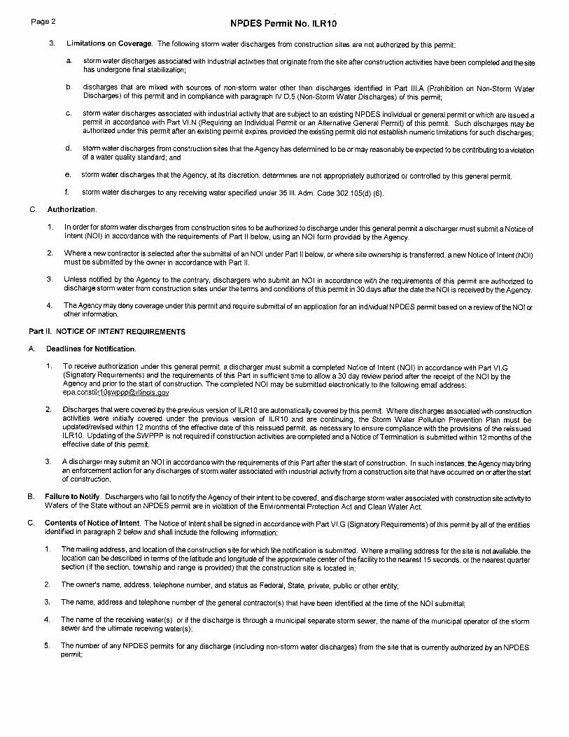


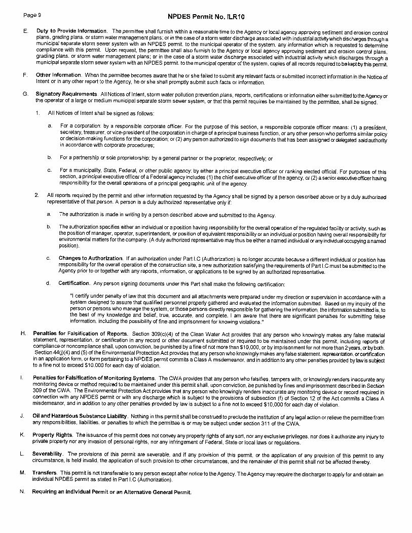

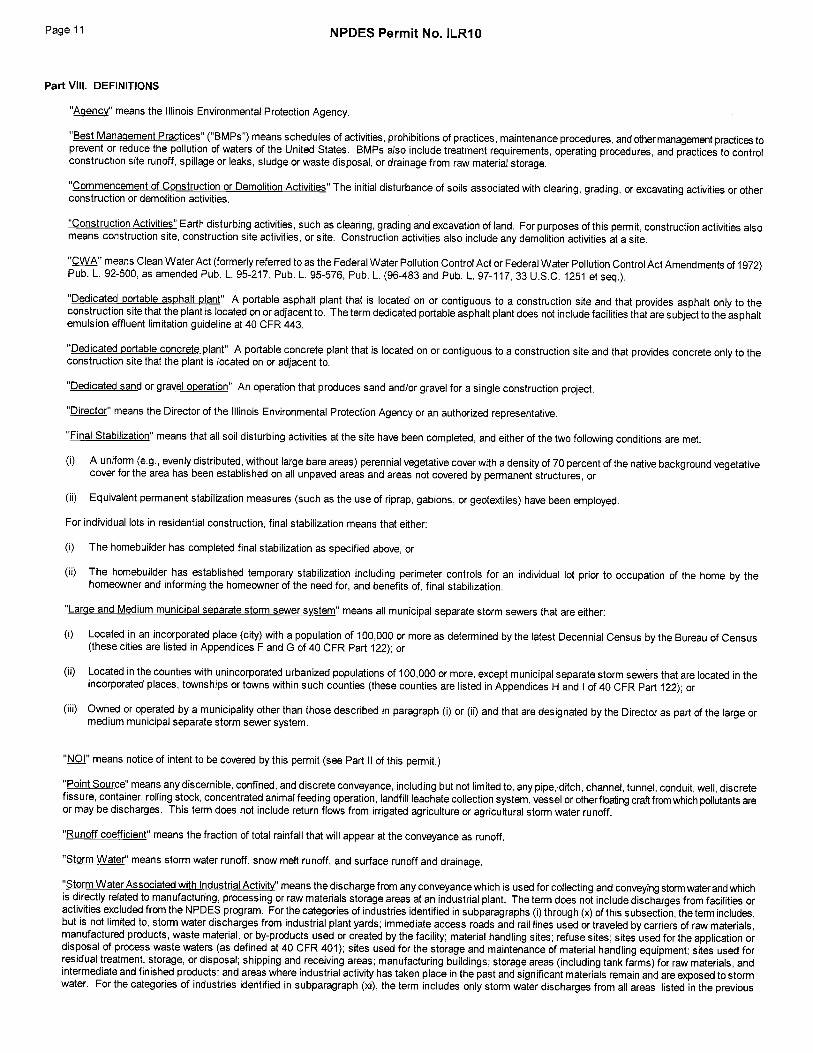
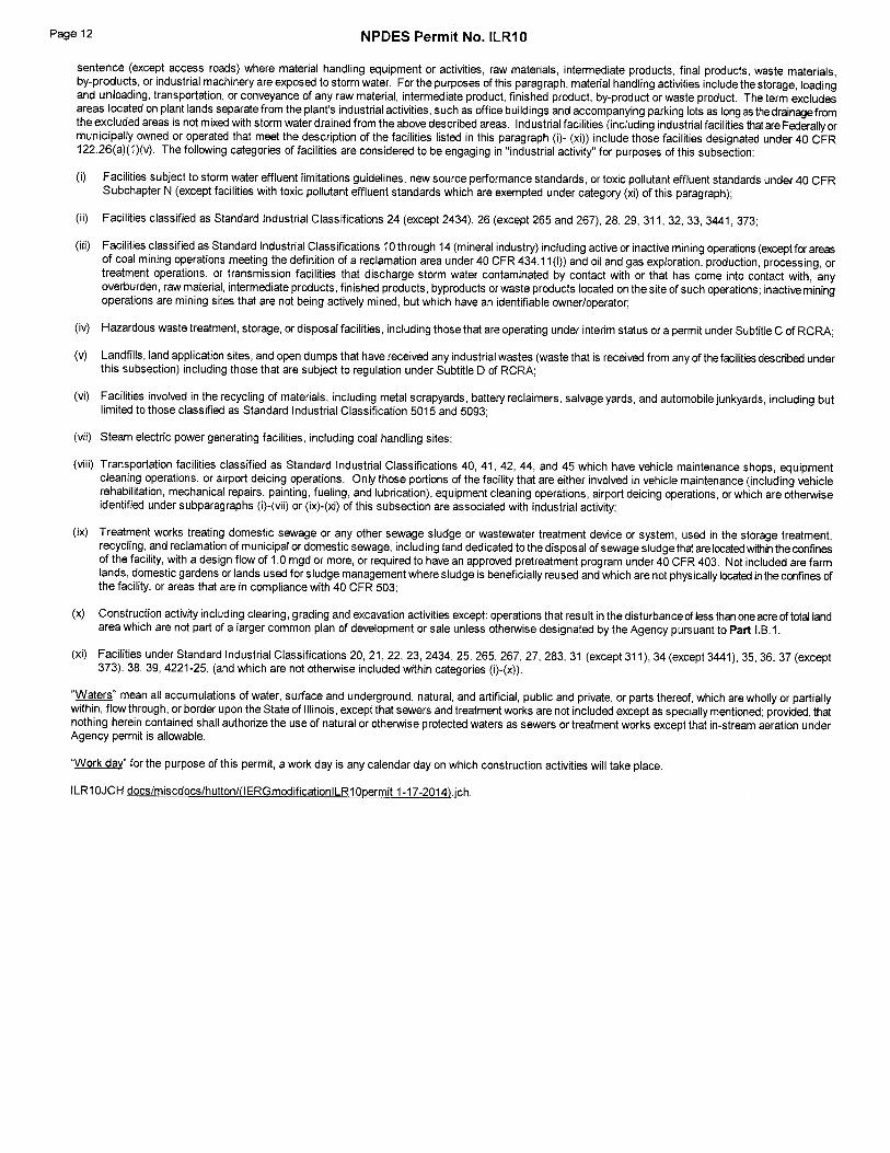
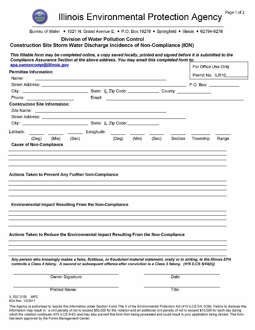
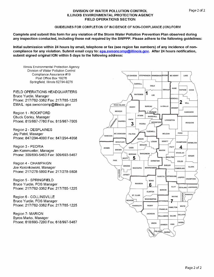

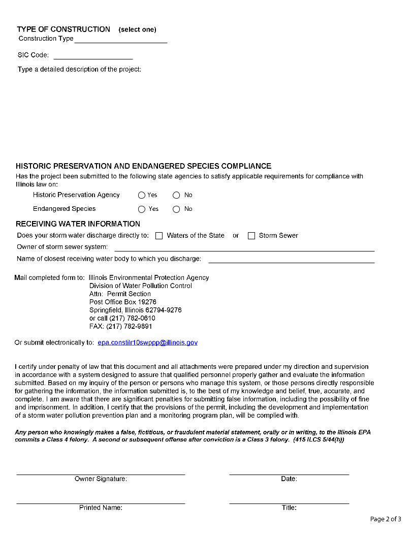
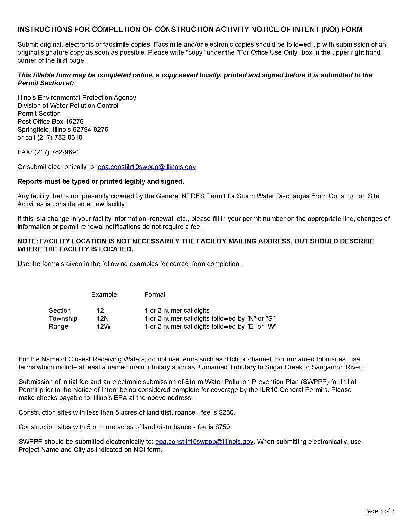


EROSION AND SEDIMENT CONTROL, LANDSCAPE DESIGN CRITERIA
March 2017
THIS PAGE INTENTIONALLY LEFT BLANK

EROSION AND SEDIMENT CONTROL, LANDSCAPE DESIGN CRITERIA
March 2017
APPENDIX 2
EPA’s Stormwater Phase II Final Rule, SmallConstruction Program Overview

EROSION AND SEDIMENT CONTROL, LANDSCAPE DESIGN CRITERIA
March 2017
THIS PAGE INTENTIONALLY LEFT BLANK


EROSION AND SEDIMENT CONTROL, LANDSCAPE DESIGN CRITERIA
March 2017
THIS PAGE INTENTIONALLY LEFT BLANK

EROSION AND SEDIMENT CONTROL, LANDSCAPE DESIGN CRITERIA
March 2017
APPENDIX 3
Illinois Tollway – Sample Erosion Control Plans

EROSION AND SEDIMENT CONTROL, LANDSCAPE DESIGN CRITERIA
March 2017
THIS PAGE INTENTIONALLY LEFT BLANK

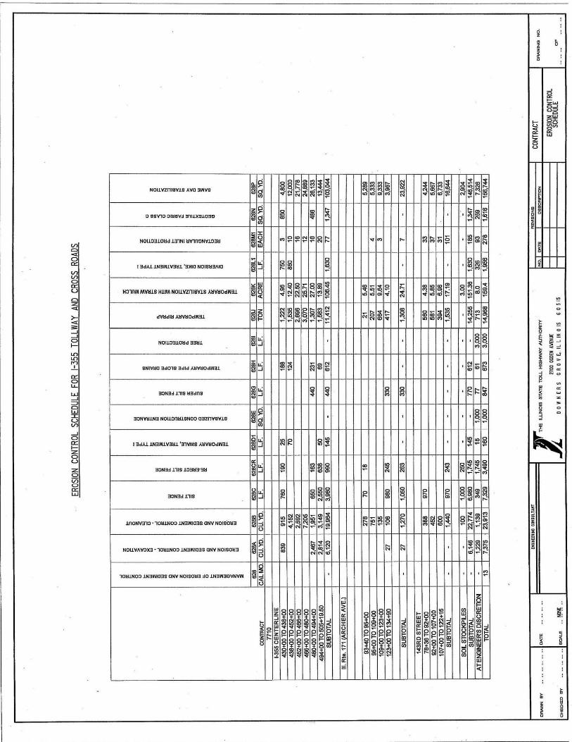
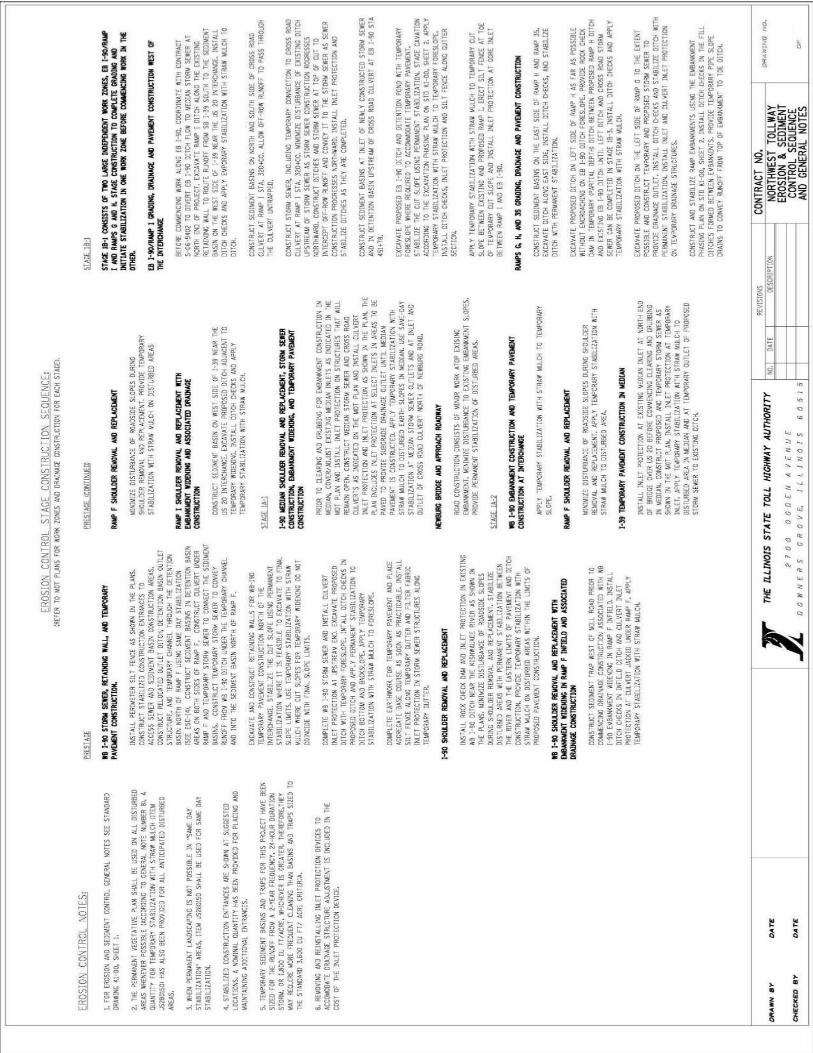


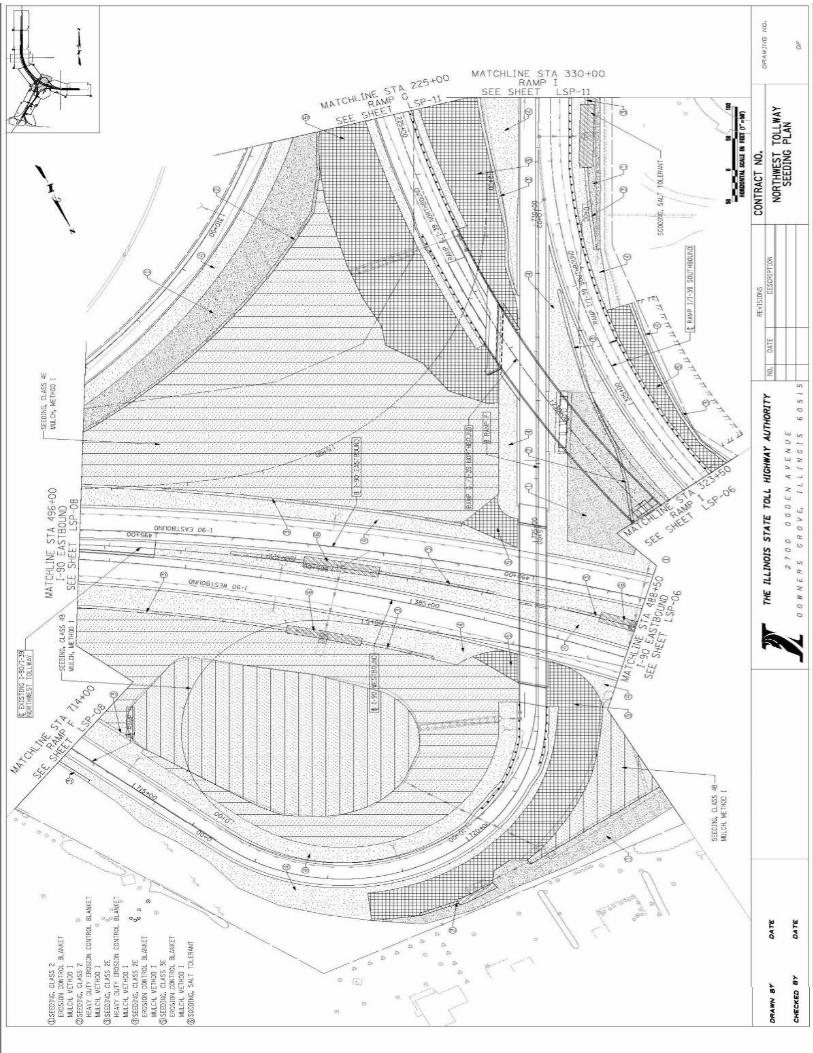


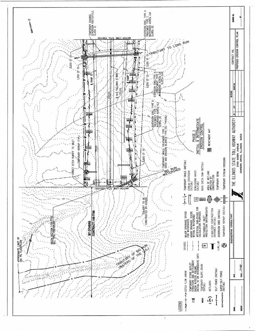

EROSION AND SEDIMENT CONTROL, LANDSCAPE DESIGN CRITERIA
March 2017
APPENDIX 4
Illinois Tollway - Erosion and Sediment Control Plan Technical Review Checklist

EROSION AND SEDIMENT CONTROL, LANDSCAPE DESIGN CRITERIA
March 2017
THIS PAGE INTENTIONALLY LEFT BLANK
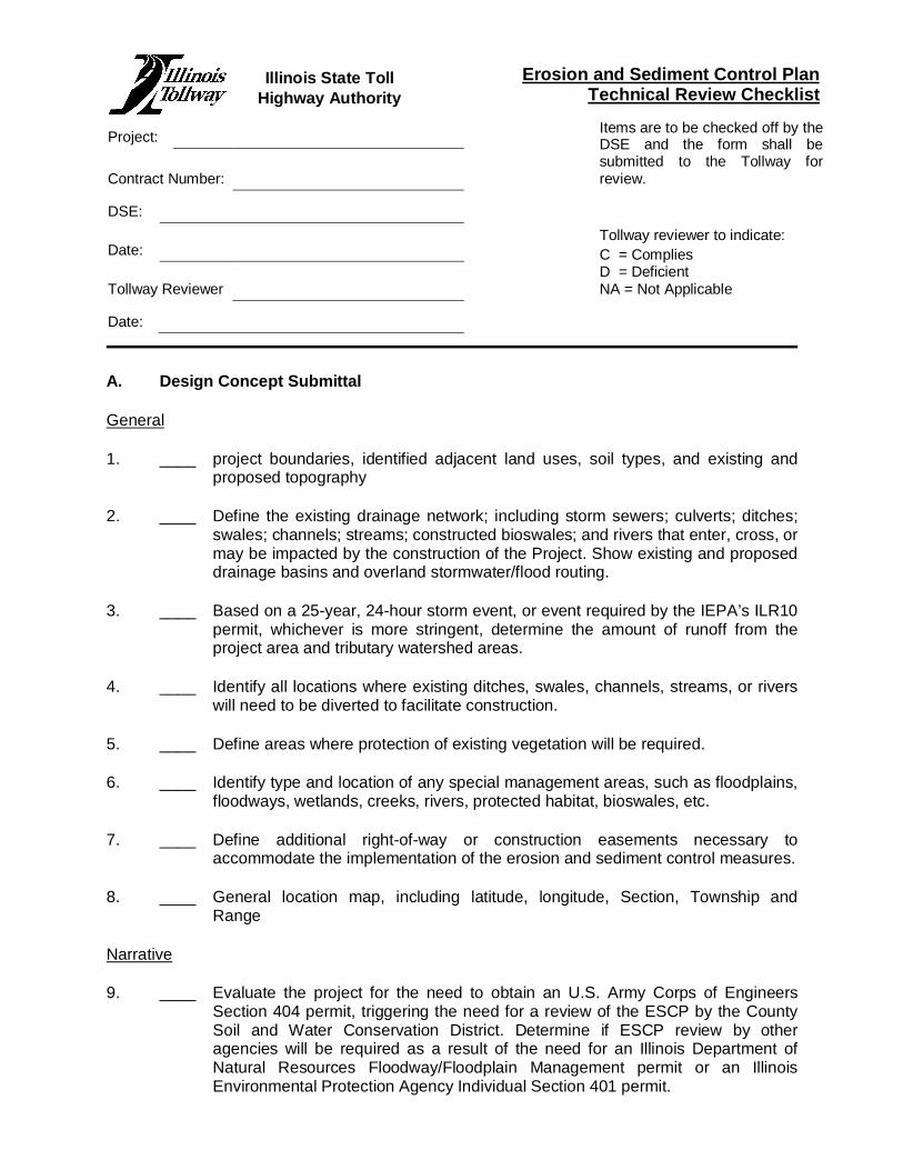
Erosion and Sediment Control Plan Technical Review Checklist
Project: Items are to be checked off by theDSE and the form shall besubmitted to the Tollway forreview.Contract Number:
DSE:
Date:Tollway reviewer to indicate:C = CompliesD = DeficientNA = Not ApplicableTollway Reviewer
Date:
A. Design Concept Submittal
General
1. ____ project boundaries, identified adjacent land uses, soil types, and existing andproposed topography
2. ____ Define the existing drainage network; including storm sewers; culverts; ditches;swales; channels; streams; constructed bioswales; and rivers that enter, cross, ormay be impacted by the construction of the Project. Show existing and proposeddrainage basins and overland stormwater/flood routing.
3. ____ Based on a 25-year, 24-hour storm event, or event required by the IEPA’s ILR10permit, whichever is more stringent, determine the amount of runoff from theproject area and tributary watershed areas.
4. ____ Identify all locations where existing ditches, swales, channels, streams, or riverswill need to be diverted to facilitate construction.
5. ____ Define areas where protection of existing vegetation will be required.
6. ____ Identify type and location of any special management areas, such as floodplains,floodways, wetlands, creeks, rivers, protected habitat, bioswales, etc.
7. ____ Define additional right-of-way or construction easements necessary toaccommodate the implementation of the erosion and sediment control measures.
8. ____ General location map, including latitude, longitude, Section, Township andRange
Narrative
9. ____ Evaluate the project for the need to obtain an U.S. Army Corps of EngineersSection 404 permit, triggering the need for a review of the ESCP by the CountySoil and Water Conservation District. Determine if ESCP review by otheragencies will be required as a result of the need for an Illinois Department ofNatural Resources Floodway/Floodplain Management permit or an IllinoisEnvironmental Protection Agency Individual Section 401 permit.
Illinois State TollHighway Authority

10. ____ Evaluate project site requirements for NPDES Permit No. ILR10 – Storm WaterDischarges From Construction Activities.
11. ____ Evaluate project site requirements for County Stormwater Management Agencyrequirements.
12. ____ Begin necessary coordination related to National Historic Preservation Act andEndangered Species Act compliance. Per requirements of NPDES Permit No.ILR10 – Storm Water Discharges From Construction Activities, informationrelated to this coordination must be provided as part of the Notice of Intent (NOI).The DSE will develop draft documents suitable for submission to the IllinoisHistoric Preservation Agency and U.S. Fish and Wildlife Service, as necessary.Draft documents will be provided to the Tollway Environmental Unit for theirsubmission to these agencies.
13. ____ Provide narrative summarizing the project site evaluation, strategy for runoffcontrol, rationalization for choice of BMPs, regulatory and resource agencycoordination, and the overall erosion and sediment control concept. The narrativeshall include a thorough explanation of the conclusions reached from the projectsite evaluation and governmental and regulatory coordination.
Overview Drawings at 1” = 100’
14. ____ conceptual proposed conditions, including contours, drainage patterns, stormconveyance systems, and possible BMPs
15. ____ project centerline stationing and ramp baseline, as applicable
16. ____ existing and proposed roadway geometry
17. ____ right-of-way limits
18. ____ existing contours (half tone)
19. ____ drainage areas tributary to the project and within project limits
20. ____ existing drainage network, including storm sewers, culverts, bridges, swales,ditches, channels, creeks, streams, rivers, constructed bioswales, and waterwaynames
21. ____ floodplain and floodway limits, with elevations clearly noted
22. ____ size of bridges, storm sewer/s, culverts, and existing outlets
23. ____ type and location of any special management areas
24. ____ location, size, and I.D. number of existing wetland areas, other environmentallysensitive areas, and which portions of these (if any) will be impacted
Other
25. ____ work stage drawing(s) that define the suggested sequencing of construction tolimit the size of the area disturbed at one time to 20 acres

26. ____ Submit the Environmental Studies Inventory Sheet and the Erosion andSediment Control Analysis form contained in the Tollway Environmental StudiesManual.
27. ____ rough cost estimate, including any additional right-of-way costs for implementingthe ESCP
B. Preliminary Design Submittal
General
1. ____ Identify hydric or potentially erodible soils. Based on soils report information,refine soil classifications and adjust ESCP concept, as necessary.
2. ____ Address, in writing, all Tollway comments from previous submittal.
3. ____ Provide overview drawings reflecting any revisions called for in the previousreview.
Drawings at 1” = 50’
4. ____ Show all information provided on overview drawings, including existing contour athalf tone and proposed contours at full tone.
5. ____ Provide plan sheet EC-1, Erosion and Sediment Control Plan, and StandardSymbols. Show standard symbols, non standard symbols, abbreviations, andspecial construction details (if necessary). See Appendix 3 of the Tollway’sErosion and Sediment Control, Landscape Design Criteria manual and TollwayStandard K Drawings.
6. ____ Provide plan sheet EC-2, Erosion Control Schedule, and Materials Schedule.Summarize, by drawing number, the measures to be installed, pay items, payitem numbers, and quantities. Include a column for Record Quantities for use bythe CSE.
Provide additional quantities over and above the plan quantities for use “AtEngineer’s Discretion”. Coordinate these quantities with Tollway ProjectEngineers prior to submitting plans (see Appendix 3).
7. ____ Provide plan sheet EC-3, Erosion Control Sequences and General Notes. Showmaintenance schedule for each erosion control practice with parties responsiblefor maintenance, i.e., Landscape Contractor or General Contractor. Showconstruction sequences for installing control measures in relation to specificstages of construction and earth disturbance activities. Show the followinggeneral notes:
____a) For erosion and sediment control general notes, see Standard DrawingsK1 and K2.
____b) The permanent vegetative plan shall be used on all disturbed areaswhenever possible (according to general note number 8). A quantity fortemporary stabilization with straw mulch (Item 280.15) has also beenprovided for all anticipated disturbed areas.
____c) When permanent landscaping is not possible in “Same Day Stabilization”areas, Item 280.15 shall be used for same day stabilization.
____d) Temporary sediment basin #____ and temporary sediment traps #____have been sized using 1800 cubic feet/acre storage and may need morefrequent cleaning than traps sized to the standard 3600 cubic feet/acrecriteria.
____e) Stabilized construction entrances shown at suggested locations. Anominal quantity has been provided for placing and maintaining additionalentrances(s).
8. ____ Delineate disturbed area and provide drainage patterns for proposed conditions.Make special note of drainage areas used to size the perimeter controls,sediment traps, or retention basins.
9. ____ Direction of runoff flow prior to construction, during construction, and afterconstruction is completed. This may require duplicate drawings in somesituations.
10. ____ Identify reaches that will require use of staged construction with temporary orpermanent stabilization of slopes before additional excavation or placement of fill.Label how many stages/phases of construction will be needed, with the slopelength (50 feet) and/or 15 feet fill or cut limitations shown on Tollway StandardDrawing K1, at representative (20 acre) locations along the route.
11. ____ borrow sites and topsoil stockpile locations, including applicable ESC measures.
12. ____ Identify and quantity all tree protection and sediment control measures that mustbe in place prior to start of grading. These include sediment basins, sedimenttraps, and silt fences. These practices shall be identified on the plan as InitialConstruction.
13. ____ Identify locations where temporary stream diversions will be needed forinstallation of culverts or bridges. These measures shall be identified on the planas Initial Construction.
14. ____ Identify and quantify the permanent and temporary storm water practices thatmust be in place before grading occurs in each specific area along the route.These include storm water detention sites, stabilized channel outlets, stabilizedtemporary swales or diversion dikes, and any needed stream diversions. Notesshall be placed on the drawings identifying which of the runoff control practicesand sediment control measures are to be installed prior to the start of grading.Most of these will fall in the category of perimeter controls. These practices shallbe identified as Initial Construction.
15. ____ Identify reaches that will have temporary pipe slope drains and temporary berms(fill areas).
16. ____ Show the area, in acres, controlled by each temporary sediment basin, sedimenttrap, temporary diversion, temporary swale, or other temporary measure.
17. ____ Show the location, size, and storage capacity of all detention basins to beconstructed for storm water management. Add notes if any portion of the basin isdesigned to serve as a sediment trap/basin.
18. ____ Layout the ESCP showing type and location of erosion and sediment controlmeasures to be used. Annotate as needed to get design intent across. Completedetailing is not required at this phase.
19. ____ Provide provisions for dust control watering and other pollution control measures.
Other
20. ____ preliminary cost estimate
21. ____ preliminary Special Provisions
22. ____ any additional information required by the Tollway Project Engineer
23. ____ provide Permanent Landscape Plans at 1” = 50’ showing final landscape postconstruction features and permanent seeding. Refer to Section II Landscape forrequirements.
C. Pre-Final Design Submittal
General
1. ____ Address, in writing, all Tollway comments from previous submittal.
2. ____ overview drawings
Drawings at 1” = 50’
3. ____ Identify any erosion or sediment control measures that will serve as permanenterosion control measures remaining after construction is complete.
4. ____ Identification number, volume, length, width, bottom elevation and cleanoutelevation of sediment traps and sediment basins shall be shown on the drawings.
5. ____ Sediment traps, sediment basins, dewatering basins, temporary swales andtemporary channel diversions shall be drawn on the cross sections andsubmitted for review to verify that the devices fin in the intended area.
6. ____ Label the specific location(s), size and length of all erosion and sediment controlmeasures shown on the drawings.
7. ____ Provide the dimension, material and installation details for all erosion andsediment control measures and facilities not covered by the Standard Drawings.
8. ____ Provide a maintenance schedule on sheet EC-3 for any special measures notcovered in the standard drawings and specifications.
Other
9. ____ pre-final cost estimate
10. ____ pre-final Special Provisions
11. ____ prepare Storm Water Pollution Prevention Plan (SWPPP). The DSE shall modifySpecial Provisions 111.2 to satisfy this requirement.

12. ____ any additional information required by the Tollway Project Engineer
13. ____ NPDES NOI form
14. ____ County Soil and Water Conservation District form, checklist and narrative(provide only if required because of a Section 404 permit)
15. ____ County Stormwater Management Agency submittal (if required)
16. ____ submittal information for other agencies, as required
D. Final Design Submittal
1. ____ Address, in writing, all Tollway comments from previous submittals.
2. ____ final overview and ESCP drawings
3. ____ final Special Provisions and SWPPP in Special Provision 111.2
4. ____ final cost estimate
5. ____ Professional Engineer’s seal and signature on plans
6. ____ any additional information required by the Tollway Project Engineer
7. ____ final schedule of materials
EROSION AND SEDIMENT CONTROL, LANDSCAPE DESIGN CRITERIA
March 2017
APPENDIX 5
Illinois Tollway – Stabilized Construction Entrance/Exit

EROSION AND SEDIMENT CONTROL, LANDSCAPE DESIGN CRITERIA
March 2017
THIS PAGE INTENTIONALLY LEFT BLANK
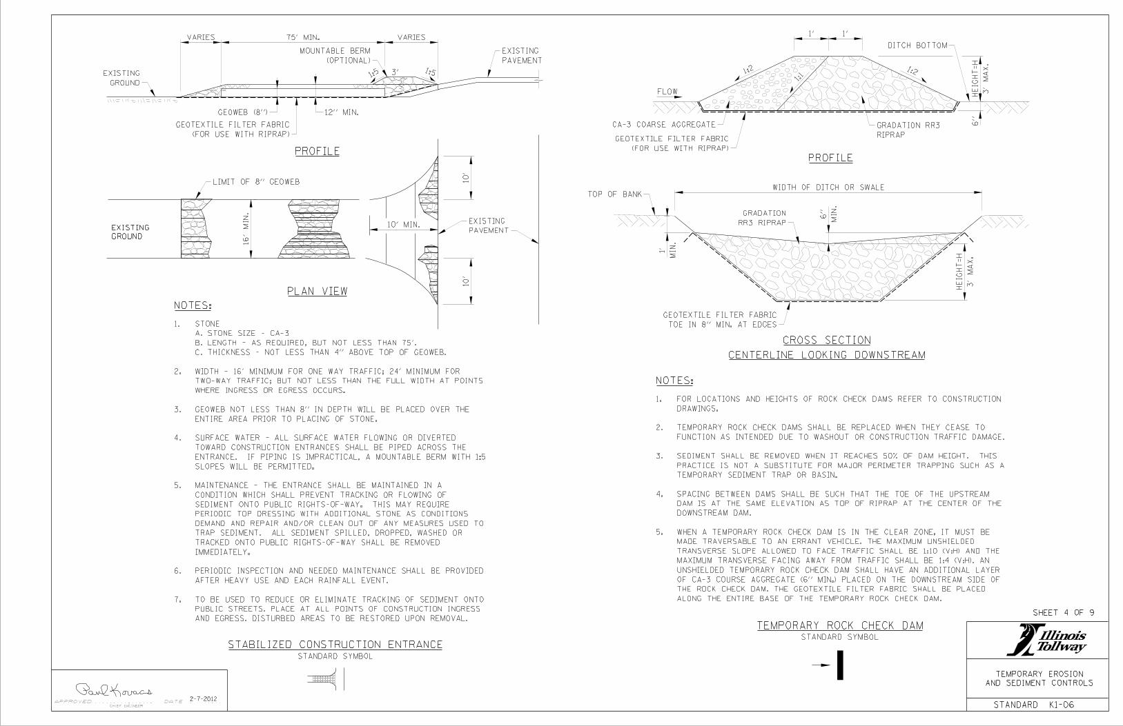
STANDARD K1-06
AND SEDIMENT CONTROLS
TEMPORARY EROSION
APPROVED DATE
CHIEF ENGINEER
2-7-2012
SHEET 4 OF 9
NOTES:
PLAN VIEW
PROFILEPROFILE
CROSS SECTION
CENTERLINE LOOKING DOWNSTREAM
NOTES:
TEMPORARY ROCK CHECK DAM
STABILIZED CONSTRUCTION ENTRANCE
GROUND
EXISTING
STANDARD SYMBOL
STANDARD SYMBOL
GROUND
EXISTING1:53'
PAVEMENT
EXISTING
VARIES75' MIN.VARIES
(OPTIONAL)
MOUNTABLE BERM
GEOWEB (8")
(FOR USE WITH RIPRAP)
GEOTEXTILE FILTER FABRIC
12" MIN.
LIMIT OF 8" GEOWEB
16'
MIN.
10' MIN.
10'
10'
PAVEMENT
EXISTING
FLOW
CA-3 COARSE AGGREGATE
(FOR USE WITH RIPRAP)
GEOTEXTILE FILTER FABRICRIPRAP
GRADATION RR3
1'1'
3'
MA
X.
HEIG
HT
=H
6"
DITCH BOTTOM
1:21:2
1:1
WIDTH OF DITCH OR SWALETOP OF BANK
RR3 RIPRAP
GRADATION
TOE IN 8" MIN. AT EDGES
GEOTEXTILE FILTER FABRIC
3'
MA
X.
HEIG
HT
=H
MIN.
6"
MIN.
1'
AND EGRESS. DISTURBED AREAS TO BE RESTORED UPON REMOVAL.
PUBLIC STREETS. PLACE AT ALL POINTS OF CONSTRUCTION INGRESS
TO BE USED TO REDUCE OR ELIMINATE TRACKING OF SEDIMENT ONTO 7.
AFTER HEAVY USE AND EACH RAINFALL EVENT.
PERIODIC INSPECTION AND NEEDED MAINTENANCE SHALL BE PROVIDED 6.
IMMEDIATELY.
TRACKED ONTO PUBLIC RIGHTS-OF-WAY SHALL BE REMOVED
TRAP SEDIMENT. ALL SEDIMENT SPILLED, DROPPED, WASHED OR
DEMAND AND REPAIR AND/OR CLEAN OUT OF ANY MEASURES USED TO
PERIODIC TOP DRESSING WITH ADDITIONAL STONE AS CONDITIONS
SEDIMENT ONTO PUBLIC RIGHTS-OF-WAY. THIS MAY REQUIRE
CONDITION WHICH SHALL PREVENT TRACKING OR FLOWING OF
MAINTENANCE - THE ENTRANCE SHALL BE MAINTAINED IN A 5.
SLOPES WILL BE PERMITTED.
ENTRANCE. IF PIPING IS IMPRACTICAL, A MOUNTABLE BERM WITH 1:5
TOWARD CONSTRUCTION ENTRANCES SHALL BE PIPED ACROSS THE
SURFACE WATER - ALL SURFACE WATER FLOWING OR DIVERTED 4.
ENTIRE AREA PRIOR TO PLACING OF STONE.
GEOWEB NOT LESS THAN 8" IN DEPTH WILL BE PLACED OVER THE 3.
WHERE INGRESS OR EGRESS OCCURS.
TWO-WAY TRAFFIC; BUT NOT LESS THAN THE FULL WIDTH AT POINTS
WIDTH - 16' MINIMUM FOR ONE WAY TRAFFIC; 24' MINIMUM FOR 2.
C. THICKNESS - NOT LESS THAN 4" ABOVE TOP OF GEOWEB.
B. LENGTH - AS REQUIRED, BUT NOT LESS THAN 75'.
A. STONE SIZE - CA-3
STONE1.
ALONG THE ENTIRE BASE OF THE TEMPORARY ROCK CHECK DAM.
THE ROCK CHECK DAM. THE GEOTEXTILE FILTER FABRIC SHALL BE PLACED
OF CA-3 COURSE AGGREGATE (6" MIN.) PLACED ON THE DOWNSTREAM SIDE OF
UNSHIELDED TEMPORARY ROCK CHECK DAM SHALL HAVE AN ADDITIONAL LAYER
MAXIMUM TRANSVERSE FACING AWAY FROM TRAFFIC SHALL BE 1:4 (V:H). AN
TRANSVERSE SLOPE ALLOWED TO FACE TRAFFIC SHALL BE 1:10 (V:H) AND THE
MADE TRAVERSABLE TO AN ERRANT VEHICLE. THE MAXIMUM UNSHIELDED
WHEN A TEMPORARY ROCK CHECK DAM IS IN THE CLEAR ZONE, IT MUST BE 5.
DOWNSTREAM DAM.
DAM IS AT THE SAME ELEVATION AS TOP OF RIPRAP AT THE CENTER OF THE
SPACING BETWEEN DAMS SHALL BE SUCH THAT THE TOE OF THE UPSTREAM 4.
TEMPORARY SEDIMENT TRAP OR BASIN.
PRACTICE IS NOT A SUBSTITUTE FOR MAJOR PERIMETER TRAPPING SUCH AS A
SEDIMENT SHALL BE REMOVED WHEN IT REACHES 50% OF DAM HEIGHT. THIS 3.
FUNCTION AS INTENDED DUE TO WASHOUT OR CONSTRUCTION TRAFFIC DAMAGE.
TEMPORARY ROCK CHECK DAMS SHALL BE REPLACED WHEN THEY CEASE TO 2.
DRAWINGS.
FOR LOCATIONS AND HEIGHTS OF ROCK CHECK DAMS REFER TO CONSTRUCTION 1.
1:5

EROSION AND SEDIMENT CONTROL, LANDSCAPE DESIGN CRITERIA
March 2017
THIS PAGE INTENTIONALLY LEFT BLANK

EROSION AND SEDIMENT CONTROL, LANDSCAPE DESIGN CRITERIA
March 2017
APPENDIX 6
Illinois Tollway – Roadside Mowing Policy

EROSION AND SEDIMENT CONTROL, LANDSCAPE DESIGN CRITERIA
March 2017
THIS PAGE INTENTIONALLY LEFT BLANK

Illinois Tollway
Roadside Mowing Guide
March 2010
TABLE OF CONTENTS
Section 1 - Roadside Vegetation Management
A.) General Appearance and Function………………………. 2
Section 2 - Mowing Guidelines
A.) Shoulder Mowing……………………………………………… 3B.) Backslope (and Interchange) Mowing………….………… 3C.) Facility Mowing………………………………………………… 4D.) Safety/Best Management Practices (BMP’s)……………. 4-5
Section 3 - Turf Management and Weed Control
A.) Vegetation Management Maps……………………………. 5B.) Herbicides and Weed Control…………………………….. 5-6C.) Marking Special Areas……………………………………….. 6D.) Mowing Equipment………………………………………….. 6
Mowing Figures……………...…………………………………….. 7-9
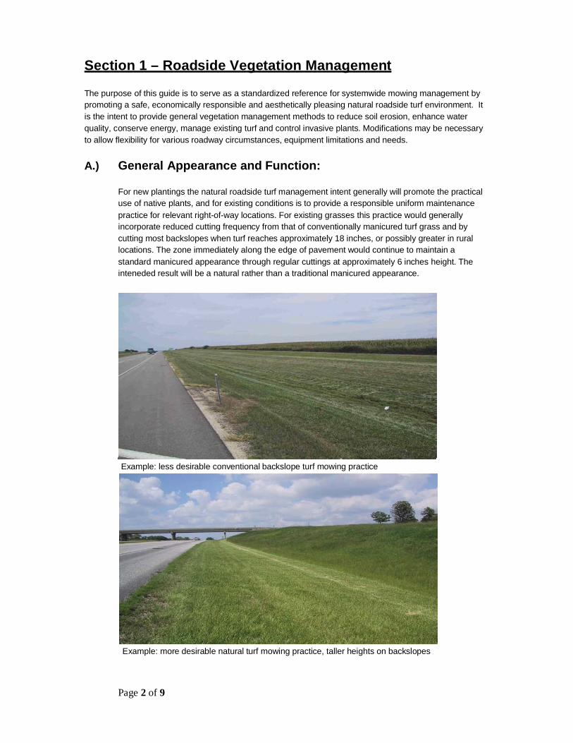
Page 2 of 9
Section 1 – Roadside Vegetation Management
The purpose of this guide is to serve as a standardized reference for systemwide mowing management bypromoting a safe, economically responsible and aesthetically pleasing natural roadside turf environment. Itis the intent to provide general vegetation management methods to reduce soil erosion, enhance waterquality, conserve energy, manage existing turf and control invasive plants. Modifications may be necessaryto allow flexibility for various roadway circumstances, equipment limitations and needs.
A.) General Appearance and Function:
For new plantings the natural roadside turf management intent generally will promote the practicaluse of native plants, and for existing conditions is to provide a responsible uniform maintenancepractice for relevant right-of-way locations. For existing grasses this practice would generallyincorporate reduced cutting frequency from that of conventionally manicured turf grass and bycutting most backslopes when turf reaches approximately 18 inches, or possibly greater in rurallocations. The zone immediately along the edge of pavement would continue to maintain astandard manicured appearance through regular cuttings at approximately 6 inches height. Theinteneded result will be a natural rather than a traditional manicured appearance.
Example: less desirable conventional backslope turf mowing practice
Example: more desirable natural turf mowing practice, taller heights on backslopes

Page 3 of 9
Section 2 – Mowing Guidelines(see figures 1, 2 and 3)
A.) Shoulder (and Median) Mowing:
Mowing Frequency: As needed, approximately 3 – 5 cycles per yearMowing Height: Minimum 6 inches
Shoulder and median cutting cycles may be made as needed to maintain a manicured appearanceand should typically begin when 50 percent of the vegetation reaches 10 inch height. Mowerequipment settings shall be adjusted to maintain the vegetation height between 6 and 12 inches.
The width of the cut shall be approximately 15 feet wide from the edge of shoulder or through theditch line and is generally intended to be one pass of the mowing equipment. This practice mayrequire a range of mowing widths to continuously manage drainage through the ditch line.
Mowing and vegetation control should be provided on all medians less than 100 feet in width.Medians 100 feet and wider may be managed at discretion of each maintenance section and isdependent upon the terrain.
B.) Backslope (and Interchange) Mow Management-
URBAN AREAS:
Mowing Frequency: Between 1 to 3 cycles per yearMowing Height: Minimum 6 inches
For the purposes of Tollway vegetation management, urban areas are defined as having asurrounding setting that is characteristic of city or town development. The start of rural locationlimits commonly begin west of the Fox River, but exact locations should be determined by eachmaintenance section.
Urban mowing of all accessible areas beyond the “Shoulder and Median Mowing” limits shalltypically be conducted between one to three mowing cycles each year. Mower equipment settingsshall be adjusted to cut vegetation once heights reach approximately 18 inches.
Mowing areas generally include, interchange infields and back-slopes to the fence line. A singlemowing pass along the fence line may be provided on a more frequent basis in areas such asthose adjacent to residential neighborhoods.
RURAL AREAS:
Mowing Frequency: Approximately 1 cycle every 1 – 2 years (less as practical)Mowing Height: Minimum 6 inches (up to 15 inches)
For the purposes of Tollway vegetation management, rural areas are defined as those outsideurban areas, generally with a surrounding setting characteristic of that beyond a city or town.
Rural mowing of all accessible areas beyond the “Shoulder and Median Mowing” limits shalltypically be conducted in one cycle every (1) one or two (2) years or less depending on site

Page 4 of 9
conditions. Mower equipment settings shall be adjusted to cut vegetation once heights reachapproximately 18 inches or higher when practical and desirable.
Mowing areas generally include, interchange infields and back-slopes to the fence line. Mowingfrequency should be evaluated each year and is intended to be the least possible to control weedgrowth and undesirable woody vegetation.
C.) Facility Mowing:
The area immediately surrounding Oasis, Toll Plazas, Maintenance Yards and other Tollwaystructures and facilities may be maintained with conventional lawn maintenance methods (ShoulderMowing and/or Traditional Mowing) of increased mowing frequency for a more manicured turfappearance. Additional care and watering may also be required to turf areas with traditionalmowing practices and should also to surrounding trees, shrubs and other ornamental plants duringthe summer months or dry periods, as needed.
D.) Safety and Best Management Practices Notes:
a.) Operator training is provided by each maintenance section and should be completed priorto use of any mowing equipment.
b.) Additional mowing may be performed in areas where vegetation impedes roadsidedrainage. If possible mowing in drainage ditches should be performed when the areas aredry to reduce turf damage and potential soil erosion.
c.) Spot mowing may be performed for noxious weed control. Blanket mowing of largerselect areas may also be provided when increase control of noxious weeds is desirableand to aesthetically blend mow areas. When cutting for weed control the timing isimportant and typically should be completed before the targeted plant flowers, reducingthe ability to propagate, but may vary for various plant types (see Section 4).
d.) Shoulder Mowing may also be expanded where lower grass heights are desirable, suchas, delineation of message signs. This shall be performed with long, smooth approachtransitions to the signage, so the mowed edge does not produce an abrupt or raggedappearance.
e.) Medians and Interchange infields less than approximately 100 feet wide shall becompletely mowed according to the regular ‘Shoulder Mowing’ cycle.
f.) Slopes greater than 2.5:1 shall not be mowed with conventional mowers.
g.) Areas with steep slopes or poor access or conditions that currently have reduced mowingrestrictions may remain as such unless otherwise directed or indicated on the vegetationmanagement maps.
h.) All mowing should be performed in a manner to prevent scalping, equipment rutting tracksor other turf and slope damage. Whenever possible mowing should not be done whenground conditions are wet or where equipment slipping could cause turf damage or lead topotential soil erosion and sediment loss.
i.) Designated locations behind noise walls may be considered for regular ‘Shoulder Mowing’practices to maintain a manicured appearance and control debris adjacent to residentialand urban locations.
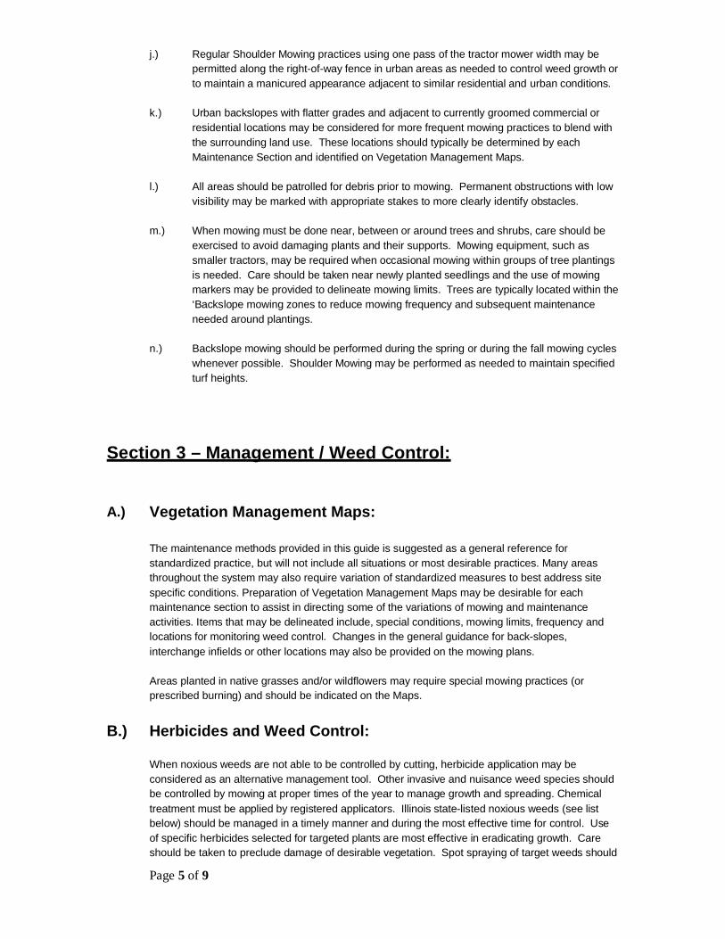
Page 5 of 9
j.) Regular Shoulder Mowing practices using one pass of the tractor mower width may bepermitted along the right-of-way fence in urban areas as needed to control weed growth orto maintain a manicured appearance adjacent to similar residential and urban conditions.
k.) Urban backslopes with flatter grades and adjacent to currently groomed commercial orresidential locations may be considered for more frequent mowing practices to blend withthe surrounding land use. These locations should typically be determined by eachMaintenance Section and identified on Vegetation Management Maps.
l.) All areas should be patrolled for debris prior to mowing. Permanent obstructions with lowvisibility may be marked with appropriate stakes to more clearly identify obstacles.
m.) When mowing must be done near, between or around trees and shrubs, care should beexercised to avoid damaging plants and their supports. Mowing equipment, such assmaller tractors, may be required when occasional mowing within groups of tree plantingsis needed. Care should be taken near newly planted seedlings and the use of mowingmarkers may be provided to delineate mowing limits. Trees are typically located within the‘Backslope mowing zones to reduce mowing frequency and subsequent maintenanceneeded around plantings.
n.) Backslope mowing should be performed during the spring or during the fall mowing cycleswhenever possible. Shoulder Mowing may be performed as needed to maintain specifiedturf heights.
Section 3 – Management / Weed Control:
A.) Vegetation Management Maps:
The maintenance methods provided in this guide is suggested as a general reference forstandardized practice, but will not include all situations or most desirable practices. Many areasthroughout the system may also require variation of standardized measures to best address sitespecific conditions. Preparation of Vegetation Management Maps may be desirable for eachmaintenance section to assist in directing some of the variations of mowing and maintenanceactivities. Items that may be delineated include, special conditions, mowing limits, frequency andlocations for monitoring weed control. Changes in the general guidance for back-slopes,interchange infields or other locations may also be provided on the mowing plans.
Areas planted in native grasses and/or wildflowers may require special mowing practices (orprescribed burning) and should be indicated on the Maps.
B.) Herbicides and Weed Control:
When noxious weeds are not able to be controlled by cutting, herbicide application may beconsidered as an alternative management tool. Other invasive and nuisance weed species shouldbe controlled by mowing at proper times of the year to manage growth and spreading. Chemicaltreatment must be applied by registered applicators. Illinois state-listed noxious weeds (see listbelow) should be managed in a timely manner and during the most effective time for control. Useof specific herbicides selected for targeted plants are most effective in eradicating growth. Careshould be taken to preclude damage of desirable vegetation. Spot spraying of target weeds should

Page 6 of 9
be the first consideration in chemical control. Blanket spraying should only be used in areascontaining high concentrations of the target weeds when other options are not effective.
Illinois Noxious weeds List (as of current printing):
1. Marihuana (Cannabis sativa L.)2. Giant Ragweed (Ambrosia trifida L.)3. Common Ragweed (Ambrosia artemisiifolia L.)4. Canada Thistle (Cirsium arvense)5. Perennial Sowthistle (Sonchus arvensis)6. Musk Thistle (Carduus nutans)7. Perennial sorghum types, including Johnsongrass (Sorghum halepense)8. Kudzu (Pueraria labata)
Other common invasive or nuisance weeds include, but not limited to:
1. Leafy Spurge2. Purple Loosestrife3. Garlic Mustard4. Reed Canary Grass5. White and Yellow Sweet Clover6. Cut-leaf and Common Teasel
Effective and safe weed management control may be developed for problem areas by contactingthe USDA Midwest Area Weed Management Unit.
C.) Marking Limits for Special Mow Areas:
Selective mowing stakes (Article 250.08 of the Standard Specifications) may be used to delineatemowing lines for special mowing practices of wildflower, wetland and/or other conservation areasrequiring guidance of mower operations.
When the complete right-of-way is mowed, use extra care in areas beyond the clear zone toidentify and save desirable volunteer trees and shrubs.
D.) Mowing Equipment:
Large tractors with flail or rotary mowing equipment attachments are used for most roadwaymowing conditions.
Smaller rotary tractors and/or hand mowing equipment should be used in locations that are noteasily accessible to larger tractor units. These locations may include, between tree groupings,around culvert inlets and outlets, near building facilities or other locations that may cause unwanteddamage to desirable vegetation or structures.
Slope mowers are designed for use on slopes steeper than 3 to 1. These mowers are equippedwith proper center-of-gravity mechanics and can maneuver slopes safely while reducing damage toslopes. The equipment should be operated as provided by each manufacturer.
All mowing equipment should be checked to confirm the proper mowing deck heights are set priorto cutting. Adjustments to mowing equipment may be considered to achieve higher cuts ifdesirable and beneficial, particularly for rural backslope and interchanges. Adjustments, changesor additions to mowing equipment should be coordinated with specific manufactures to provide saferesults.
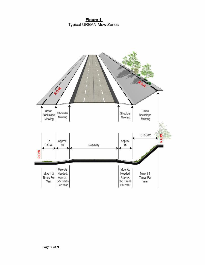
Page 7 of 9
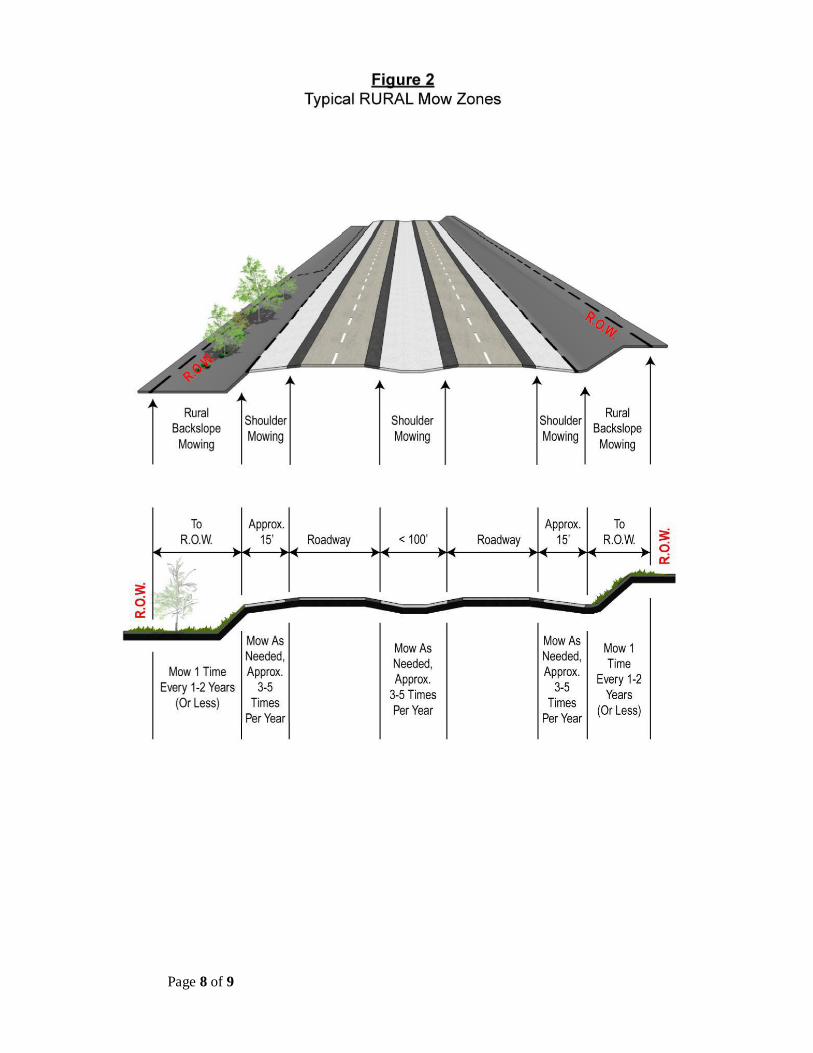
Page 8 of 9
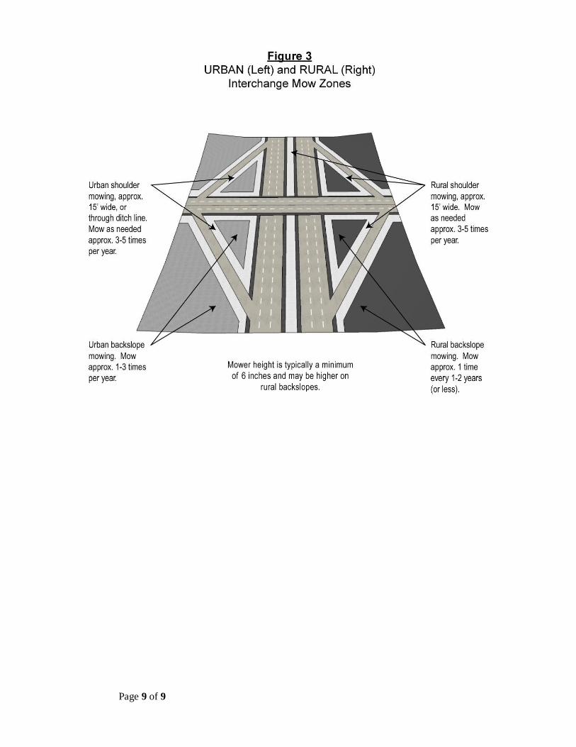
Page 9 of 9
EROSION AND SEDIMENT CONTROL, LANDSCAPE DESIGN CRITERIA
March 2017
THIS PAGE INTENTIONALLY LEFT BLANK
EROSION AND SEDIMENT CONTROL, LANDSCAPE DESIGN CRITERIA
March 2017
APPENDIX 7
Illinois Tollway – Landscape Design SubmittalChecklist

EROSION AND SEDIMENT CONTROL, LANDSCAPE DESIGN CRITERIA
March 2017
THIS PAGE INTENTIONALLY LEFT BLANK
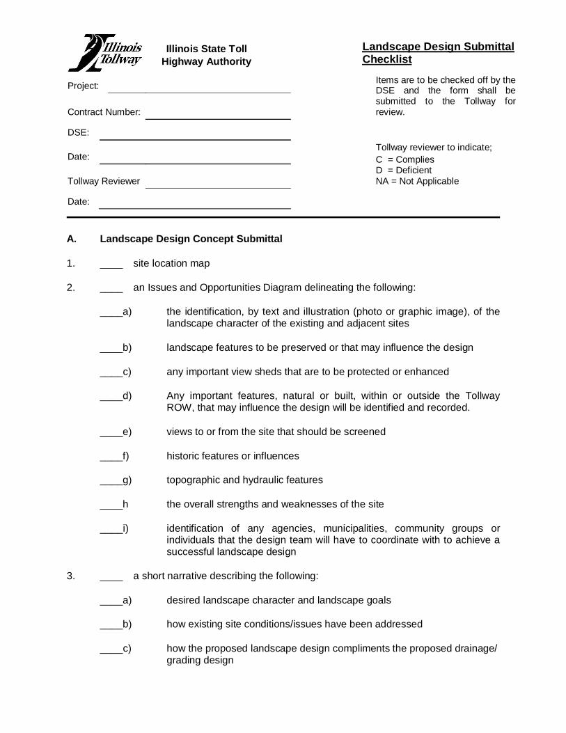
Landscape Design SubmittalChecklist
Project: Items are to be checked off by theDSE and the form shall besubmitted to the Tollway forreview.Contract Number:
DSE:
Date:Tollway reviewer to indicate;C = CompliesD = DeficientNA = Not ApplicableTollway Reviewer
Date:
A. Landscape Design Concept Submittal
1. ____ site location map
2. ____ an Issues and Opportunities Diagram delineating the following:
____a) the identification, by text and illustration (photo or graphic image), of thelandscape character of the existing and adjacent sites
____b) landscape features to be preserved or that may influence the design
____c) any important view sheds that are to be protected or enhanced
____d) Any important features, natural or built, within or outside the TollwayROW, that may influence the design will be identified and recorded.
____e) views to or from the site that should be screened
____f) historic features or influences
____g) topographic and hydraulic features
____h the overall strengths and weaknesses of the site
____i) identification of any agencies, municipalities, community groups orindividuals that the design team will have to coordinate with to achieve asuccessful landscape design
3. ____ a short narrative describing the following:
____a) desired landscape character and landscape goals
____b) how existing site conditions/issues have been addressed
____c) how the proposed landscape design compliments the proposed drainage/grading design
Illinois State TollHighway Authority
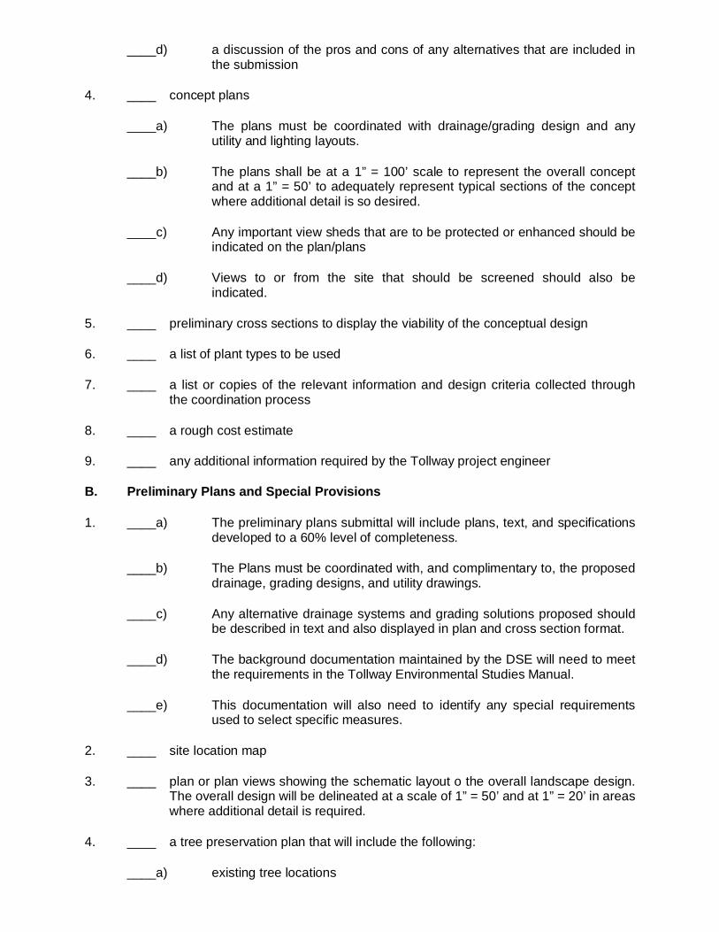
____d) a discussion of the pros and cons of any alternatives that are included inthe submission
4. ____ concept plans
____a) The plans must be coordinated with drainage/grading design and anyutility and lighting layouts.
____b) The plans shall be at a 1” = 100’ scale to represent the overall conceptand at a 1” = 50’ to adequately represent typical sections of the conceptwhere additional detail is so desired.
____c) Any important view sheds that are to be protected or enhanced should beindicated on the plan/plans
____d) Views to or from the site that should be screened should also beindicated.
5. ____ preliminary cross sections to display the viability of the conceptual design
6. ____ a list of plant types to be used
7. ____ a list or copies of the relevant information and design criteria collected throughthe coordination process
8. ____ a rough cost estimate
9. ____ any additional information required by the Tollway project engineer
B. Preliminary Plans and Special Provisions
1. ____a) The preliminary plans submittal will include plans, text, and specificationsdeveloped to a 60% level of completeness.
____b) The Plans must be coordinated with, and complimentary to, the proposeddrainage, grading designs, and utility drawings.
____c) Any alternative drainage systems and grading solutions proposed shouldbe described in text and also displayed in plan and cross section format.
____d) The background documentation maintained by the DSE will need to meetthe requirements in the Tollway Environmental Studies Manual.
____e) This documentation will also need to identify any special requirementsused to select specific measures.
2. ____ site location map
3. ____ plan or plan views showing the schematic layout o the overall landscape design.The overall design will be delineated at a scale of 1” = 50’ and at 1” = 20’ in areaswhere additional detail is required.
4. ____ a tree preservation plan that will include the following:
____a) existing tree locations
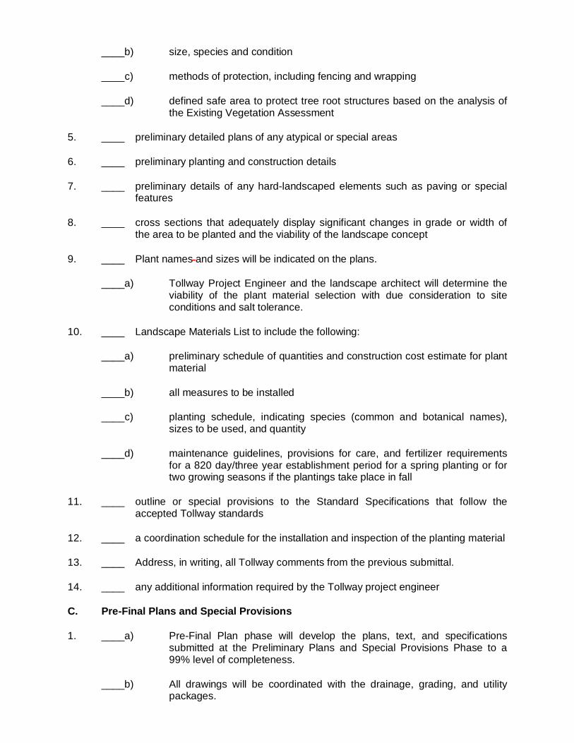
____b) size, species and condition
____c) methods of protection, including fencing and wrapping
____d) defined safe area to protect tree root structures based on the analysis ofthe Existing Vegetation Assessment
5. ____ preliminary detailed plans of any atypical or special areas
6. ____ preliminary planting and construction details
7. ____ preliminary details of any hard-landscaped elements such as paving or specialfeatures
8. ____ cross sections that adequately display significant changes in grade or width ofthe area to be planted and the viability of the landscape concept
9. ____ Plant names and sizes will be indicated on the plans.
____a) Tollway Project Engineer and the landscape architect will determine theviability of the plant material selection with due consideration to siteconditions and salt tolerance.
10. ____ Landscape Materials List to include the following:
____a) preliminary schedule of quantities and construction cost estimate for plantmaterial
____b) all measures to be installed
____c) planting schedule, indicating species (common and botanical names),sizes to be used, and quantity
____d) maintenance guidelines, provisions for care, and fertilizer requirementsfor a 820 day/three year establishment period for a spring planting or fortwo growing seasons if the plantings take place in fall
11. ____ outline or special provisions to the Standard Specifications that follow theaccepted Tollway standards
12. ____ a coordination schedule for the installation and inspection of the planting material
13. ____ Address, in writing, all Tollway comments from the previous submittal.
14. ____ any additional information required by the Tollway project engineer
C. Pre-Final Plans and Special Provisions
1. ____a) Pre-Final Plan phase will develop the plans, text, and specificationssubmitted at the Preliminary Plans and Special Provisions Phase to a99% level of completeness.
____b) All drawings will be coordinated with the drainage, grading, and utilitypackages.
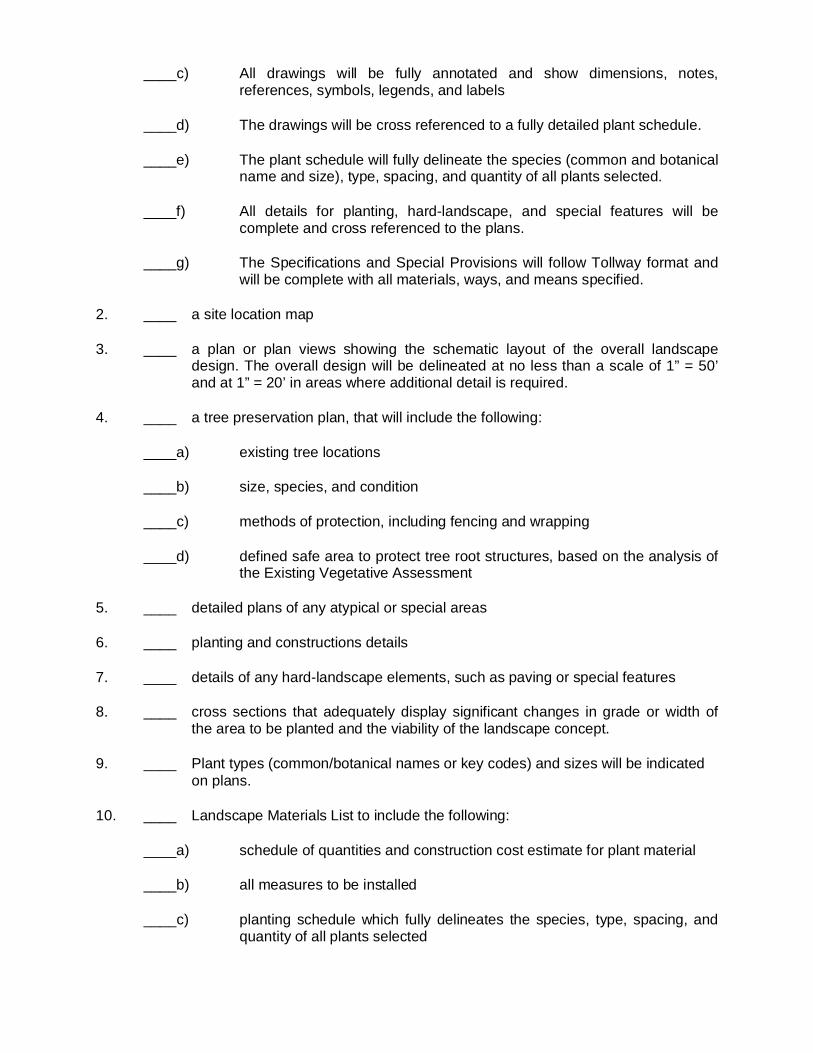
____c) All drawings will be fully annotated and show dimensions, notes,references, symbols, legends, and labels
____d) The drawings will be cross referenced to a fully detailed plant schedule.
____e) The plant schedule will fully delineate the species (common and botanicalname and size), type, spacing, and quantity of all plants selected.
____f) All details for planting, hard-landscape, and special features will becomplete and cross referenced to the plans.
____g) The Specifications and Special Provisions will follow Tollway format andwill be complete with all materials, ways, and means specified.
2. ____ a site location map
3. ____ a plan or plan views showing the schematic layout of the overall landscapedesign. The overall design will be delineated at no less than a scale of 1” = 50’and at 1” = 20’ in areas where additional detail is required.
4. ____ a tree preservation plan, that will include the following:
____a) existing tree locations
____b) size, species, and condition
____c) methods of protection, including fencing and wrapping
____d) defined safe area to protect tree root structures, based on the analysis ofthe Existing Vegetative Assessment
5. ____ detailed plans of any atypical or special areas
6. ____ planting and constructions details
7. ____ details of any hard-landscape elements, such as paving or special features
8. ____ cross sections that adequately display significant changes in grade or width ofthe area to be planted and the viability of the landscape concept.
9. ____ Plant types (common/botanical names or key codes) and sizes will be indicatedon plans.
10. ____ Landscape Materials List to include the following:
____a) schedule of quantities and construction cost estimate for plant material
____b) all measures to be installed
____c) planting schedule which fully delineates the species, type, spacing, andquantity of all plants selected
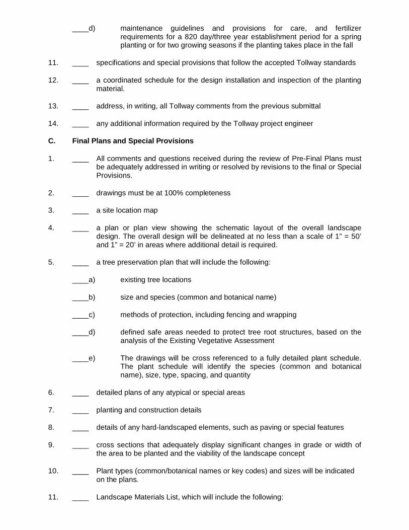
____d) maintenance guidelines and provisions for care, and fertilizerrequirements for a 820 day/three year establishment period for a springplanting or for two growing seasons if the planting takes place in the fall
11. ____ specifications and special provisions that follow the accepted Tollway standards
12. ____ a coordinated schedule for the design installation and inspection of the plantingmaterial.
13. ____ address, in writing, all Tollway comments from the previous submittal
14. ____ any additional information required by the Tollway project engineer
C. Final Plans and Special Provisions
1. ____ All comments and questions received during the review of Pre-Final Plans mustbe adequately addressed in writing or resolved by revisions to the final or SpecialProvisions.
2. ____ drawings must be at 100% completeness
3. ____ a site location map
4. ____ a plan or plan view showing the schematic layout of the overall landscapedesign. The overall design will be delineated at no less than a scale of 1” = 50’and 1” = 20’ in areas where additional detail is required.
5. ____ a tree preservation plan that will include the following:
____a) existing tree locations
____b) size and species (common and botanical name)
____c) methods of protection, including fencing and wrapping
____d) defined safe areas needed to protect tree root structures, based on theanalysis of the Existing Vegetative Assessment
____e) The drawings will be cross referenced to a fully detailed plant schedule.The plant schedule will identify the species (common and botanicalname), size, type, spacing, and quantity
6. ____ detailed plans of any atypical or special areas
7. ____ planting and construction details
8. ____ details of any hard-landscaped elements, such as paving or special features
9. ____ cross sections that adequately display significant changes in grade or width ofthe area to be planted and the viability of the landscape concept
10. ____ Plant types (common/botanical names or key codes) and sizes will be indicatedon the plans.
11. ____ Landscape Materials List, which will include the following:
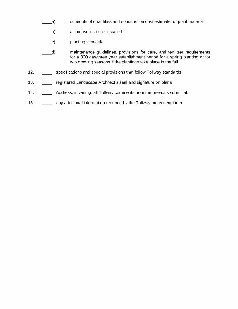
____a) schedule of quantities and construction cost estimate for plant material
____b) all measures to be installed
____c) planting schedule
____d) maintenance guidelines, provisions for care, and fertilizer requirementsfor a 820 day/three year establishment period for a spring planting or fortwo growing seasons if the plantings take place in the fall
12. ____ specifications and special provisions that follow Tollway standards
13. ____ registered Landscape Architect’s seal and signature on plans
14. ____ Address, in writing, all Tollway comments from the previous submittal.
15. ____ any additional information required by the Tollway project engineer
EROSION AND SEDIMENT CONTROL, LANDSCAPE DESIGN CRITERIA
March 2017
APPENDIX 8
Illinois Tollway – Sample Landscape Plans
EROSION AND SEDIMENT CONTROL, LANDSCAPE DESIGN CRITERIA
March 2017
THIS PAGE INTENTIONALLY LEFT BLANK
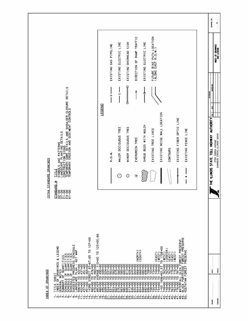


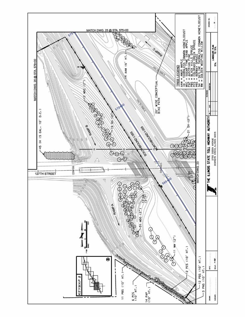


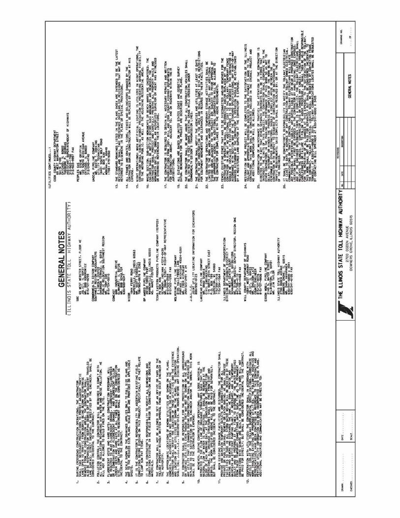
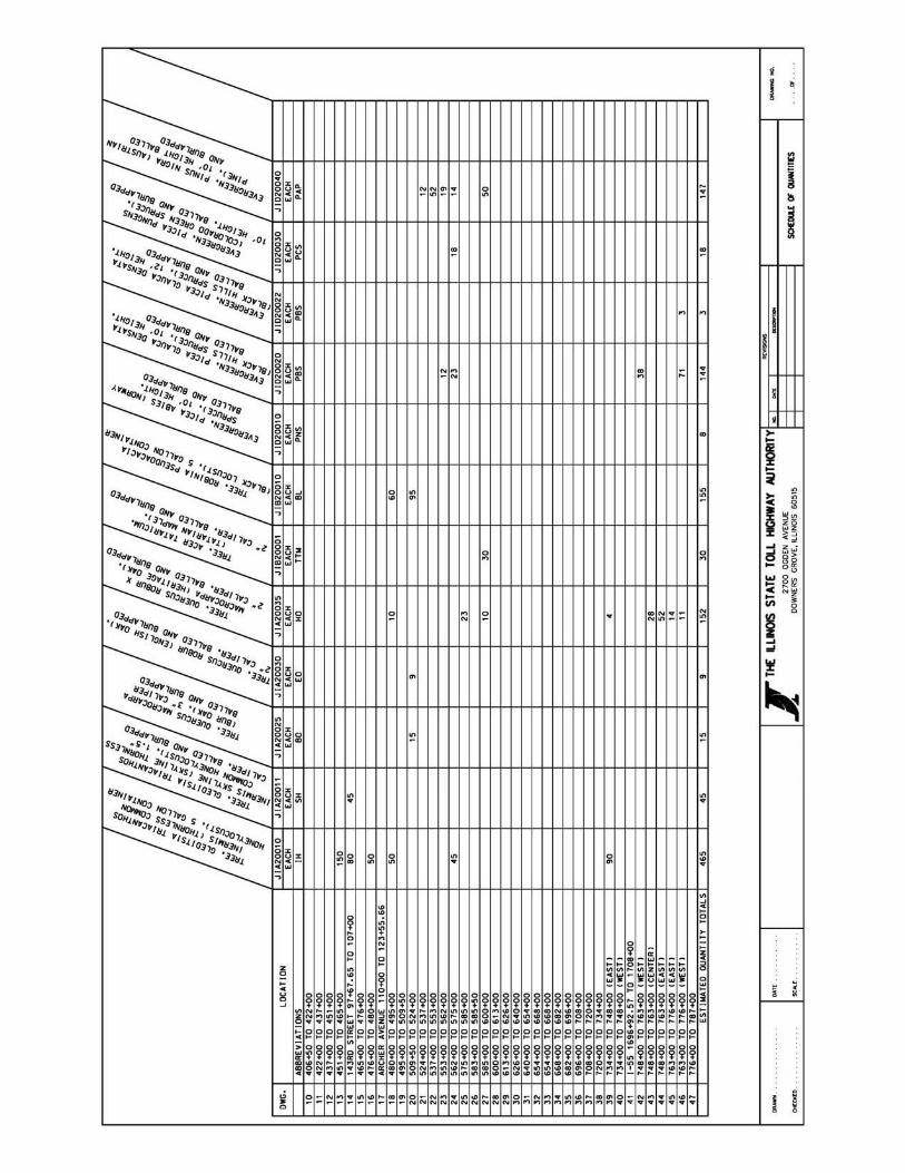
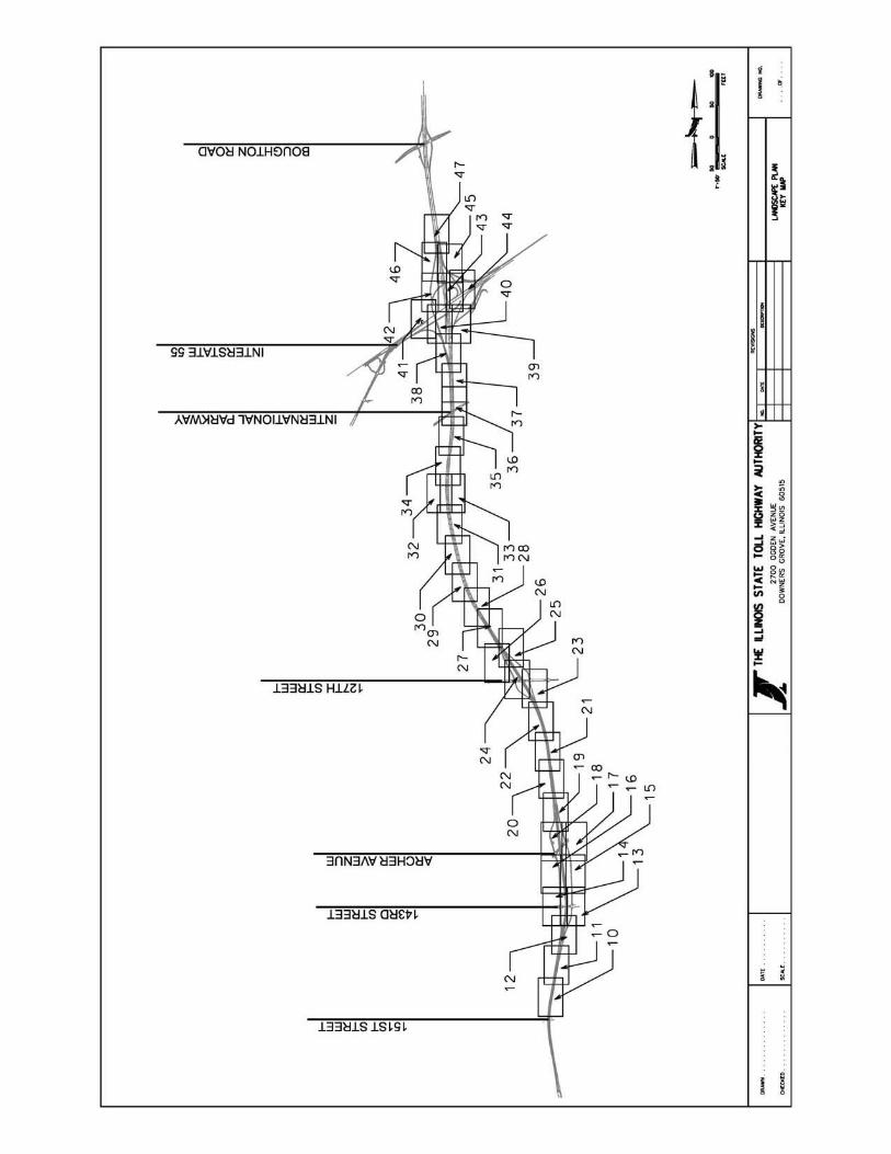

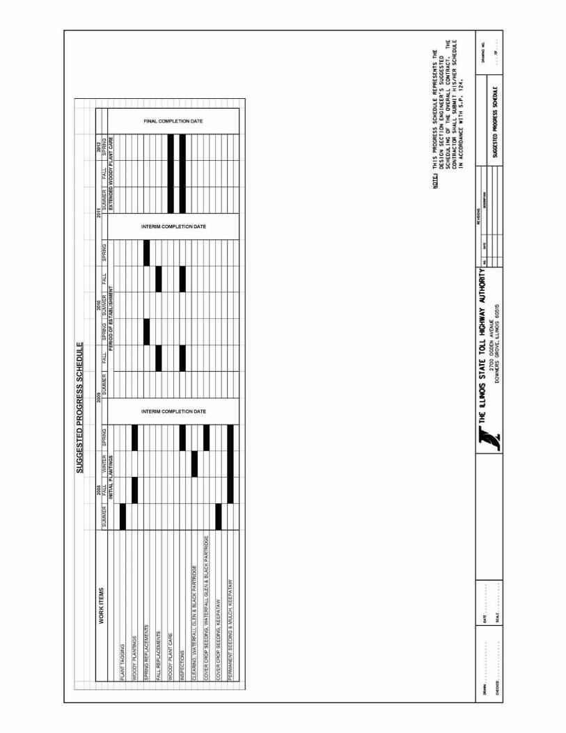
EROSION AND SEDIMENT CONTROL, LANDSCAPE DESIGN CRITERIA
March 2017
APPENDIX 9
Illinois Tollway – Preservation, Removal andReplacement of Trees
EROSION AND SEDIMENT CONTROL, LANDSCAPE DESIGN CRITERIA
March 2017
THIS PAGE INTENTIONALLY LEFT BLANK
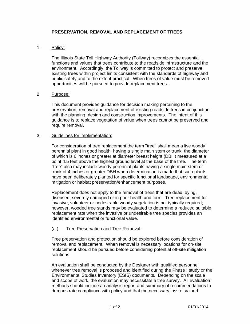
1 of 2 01/01/2014
PRESERVATION, REMOVAL AND REPLACEMENT OF TREES
1. Policy:
The Illinois State Toll Highway Authority (Tollway) recognizes the essentialfunctions and values that trees contribute to the roadside infrastructure and theenvironment. Accordingly, the Tollway is committed to protect and preserveexisting trees within project limits consistent with the standards of highway andpublic safety and to the extent practical. When trees of value must be removedopportunities will be pursued to provide replacement trees.
2. Purpose:
This document provides guidance for decision making pertaining to thepreservation, removal and replacement of existing roadside trees in conjunctionwith the planning, design and construction improvements. The intent of thisguidance is to replace vegetation of value when trees cannot be preserved andrequire removal.
3. Guidelines for implementation:
For consideration of tree replacement the term "tree" shall mean a live woodyperennial plant in good health, having a single main stem or trunk, the diameterof which is 6 inches or greater at diameter breast height (DBH) measured at apoint 4.5 feet above the highest ground level at the base of the tree. The term"tree" also may include woody perennial plants having a single main stem ortrunk of 4 inches or greater DBH when determination is made that such plantshave been deliberately planted for specific functional landscape, environmentalmitigation or habitat preservation/enhancement purposes.
Replacement does not apply to the removal of trees that are dead, dying,diseased, severely damaged or in poor health and form. Tree replacement forinvasive, volunteer or undesirable woody vegetation is not typically required;however, wooded tree stands may be evaluated to determine a reduced suitablereplacement rate when the invasive or undesirable tree species provides anidentified environmental or functional value.
(a.) Tree Preservation and Tree Removal:
Tree preservation and protection should be explored before consideration ofremoval and replacement. When removal is necessary locations for on-sitereplacement should be pursued before considering potential off-site mitigationsolutions.
An evaluation shall be conducted by the Designer with qualified personnelwhenever tree removal is proposed and identified during the Phase I study or theEnvironmental Studies Inventory (ESIS) documents. Depending on the scaleand scope of work, the evaluation may necessitate a tree survey. All evaluationmethods should include an analysis report and summary of recommendations todemonstrate compliance with policy and that the necessary loss of valued
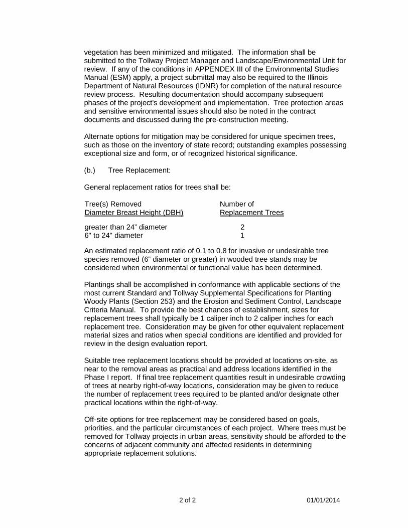
2 of 2 01/01/2014
vegetation has been minimized and mitigated. The information shall besubmitted to the Tollway Project Manager and Landscape/Environmental Unit forreview. If any of the conditions in APPENDEX III of the Environmental StudiesManual (ESM) apply, a project submittal may also be required to the IllinoisDepartment of Natural Resources (IDNR) for completion of the natural resourcereview process. Resulting documentation should accompany subsequentphases of the project's development and implementation. Tree protection areasand sensitive environmental issues should also be noted in the contractdocuments and discussed during the pre-construction meeting.
Alternate options for mitigation may be considered for unique specimen trees,such as those on the inventory of state record; outstanding examples possessingexceptional size and form, or of recognized historical significance.
(b.) Tree Replacement:
General replacement ratios for trees shall be:
Tree(s) RemovedDiameter Breast Height (DBH)
greater than 24” diameter6" to 24" diameter
Number ofReplacement Trees
2 1
An estimated replacement ratio of 0.1 to 0.8 for invasive or undesirable treespecies removed (6” diameter or greater) in wooded tree stands may beconsidered when environmental or functional value has been determined.
Plantings shall be accomplished in conformance with applicable sections of themost current Standard and Tollway Supplemental Specifications for PlantingWoody Plants (Section 253) and the Erosion and Sediment Control, LandscapeCriteria Manual. To provide the best chances of establishment, sizes forreplacement trees shall typically be 1 caliper inch to 2 caliper inches for eachreplacement tree. Consideration may be given for other equivalent replacementmaterial sizes and ratios when special conditions are identified and provided forreview in the design evaluation report.
Suitable tree replacement locations should be provided at locations on-site, asnear to the removal areas as practical and address locations identified in thePhase I report. If final tree replacement quantities result in undesirable crowdingof trees at nearby right-of-way locations, consideration may be given to reducethe number of replacement trees required to be planted and/or designate otherpractical locations within the right-of-way.
Off-site options for tree replacement may be considered based on goals,priorities, and the particular circumstances of each project. Where trees must beremoved for Tollway projects in urban areas, sensitivity should be afforded to theconcerns of adjacent community and affected residents in determiningappropriate replacement solutions.

EROSION AND SEDIMENT CONTROL, LANDSCAPE DESIGN CRITERIA
March 2017
APPENDIX 10
U.S. Department of Agriculture Plant Hardiness ZoneMap

EROSION AND SEDIMENT CONTROL, LANDSCAPE DESIGN CRITERIA
March 2017
THIS PAGE INTENTIONALLY LEFT BLANK
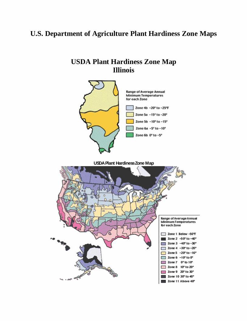
U.S. Department of Agriculture Plant Hardiness Zone Maps
USDA Plant Hardiness Zone MapIllinois
USDA Plant Hardiness Zone Map

EROSION AND SEDIMENT CONTROL, LANDSCAPE DESIGN CRITERIA
March 2017
THIS PAGE INTENTIONALLY LEFT BLANK