error codes km c2525e c3232e c4035e sm uk ref 03
TRANSCRIPT

2JL/2JJ/2JG/2JD
1-4-21
1-4-2 Self-diagnosis
(1) Self-diagnostic function
This unit is equipped with a self-diagnostic function. When a problem is detected, copying is disabled and the problem dis-played as a code consisting of C followed by a number, indicating the nature of the problem. A message is also displayedrequesting the user to call for service.After removing the problem, the self-diagnostic function can be reset by turning cover switch off and back on.
Figure 1-4-3
List of system errorsWhen an unexpected error is detected for some reason, a system error will be indicated. (When 0800 error is detected,JAM05 is indicated.) After a system error is indicated, the error can be cleared by turning the power switch off and then on.If the error is detected continuously, however, perform the operation shown in Table 1-4-1. If a system error occurs fre-quently, a fault may have occurred. Check the details of the C call to take proper measures.
Table 1-4-1
System error Contents Operation
0250 Network scanner PWB communication prob-lem
System error Normal service call processing
0410 DP communication problem (optional DP) System error Service call Partial operation control
0420 Paper feeder communication error (optional paper feeder)
System error Service call Partial operation control
0440 Document finisher communication problem (optional document finisher)
System error Service call Partial operation control
0610 Bitmap problem System error Normal service call processing
0630 DMA problem System error Normal service call processing
0640 Hard disk drive problem System error Service call Partial operation control
0800 Secondary feed time-out Repetition of JAM05 System error JAM05
3100 Scanner carriage problem System error Normal service call processing
4100 BD initialization problem System error Normal service call processing
4200 BD steady-state problem System error Normal service call processing
012345678901234
C0210
System error.
Call service.

2JL/2JJ/2JG/2JD-2
1-4-22
Partial operation controlIf one of the following service codes is detected, partial operation control will be activated. Take actions to clear the causeof the trouble and perform maintenance item U906 to reset partial operation control.
Measures against the service codes detecting fuser problemsIf one of the following service codes is detected, take actions to clear the cause of the trouble and perform maintenanceitem U163 to reset the service code.
Code Contents
C0840 Faults of RTC
C1010 Lift motor 1 error
C1020 Lift motor 2 error
C1030 Paper feeder lift motor 1 error (optional paper feeder)
C1040 Paper feeder lift motor 2 error (optional paper feeder)
C1100 Paper feeder lift motor 1 error (optional 3000-sheet paper feeder)
C1110 Paper feeder lift motor 2 error (optional 3000-sheet paper feeder)
C1120 Paper feeder left lift position problem (optional 3000-sheet paper feeder)
C1130 Paper feeder right lift position problem (optional 3000-sheet paper feeder)
C9060 EEPROM problem (optional DP)
Code Contents
C6000 Fuser heater 1/2 break
C6010 Abnormally high fuser thermistor temperature
C6020 Abnormally high fuser thermistor 1/3 temperature
C6030 Fuser thermistor 1/3 break error
C6050 Abnormally low fuser thermistor 3 temperature
C6100 Fuser heater 3 break
C6120 Abnormally high fuser thermistor 2 temperature
C6130 Fuser thermistor 2 break error
C6400 Zero-cross signal error
2JL/2JJ/2JG/2JD
1-4-23
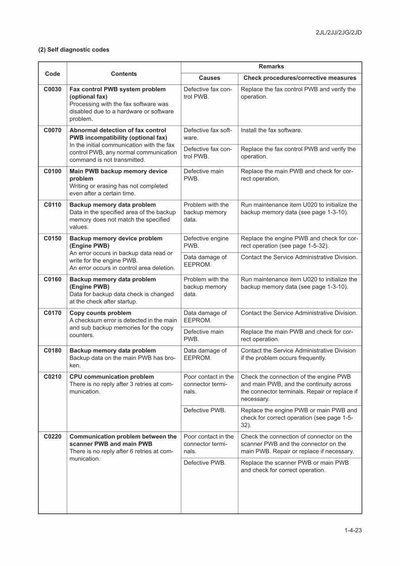
(2) Self diagnostic codes
Code ContentsRemarks
Causes Check procedures/corrective measures
C0030 Fax control PWB system problem (optional fax)Processing with the fax software was disabled due to a hardware or software problem.
Defective fax con-trol PWB.
Replace the fax control PWB and verify the operation.
C0070 Abnormal detection of fax control PWB incompatibility (optional fax)In the initial communication with the fax control PWB, any normal communication command is not transmitted.
Defective fax soft-ware.
Install the fax software.
Defective fax con-trol PWB.
Replace the fax control PWB and verify the operation.
C0100 Main PWB backup memory device problemWriting or erasing has not completed even after a certain time.
Defective main PWB.
Replace the main PWB and check for cor-rect operation.
C0110 Backup memory data problemData in the specified area of the backup memory does not match the specified values.
Problem with the backup memory data.
Run maintenance item U020 to initialize the backup memory data (see page 1-3-10).
C0150 Backup memory device problem (Engine PWB)An error occurs in backup data read or write for the engine PWB.An error occurs in control area deletion.
Defective engine PWB.
Replace the engine PWB and check for cor-rect operation (see page 1-5-32).
Data damage of EEPROM.
Contact the Service Administrative Division.
C0160 Backup memory data problem (Engine PWB)Data for backup data check is changed at the check after startup.
Problem with the backup memory data.
Run maintenance item U020 to initialize the backup memory data (see page 1-3-10).
C0170 Copy counts problemA checksum error is detected in the main and sub backup memories for the copy counters.
Data damage of EEPROM.
Contact the Service Administrative Division.
Defective main PWB.
Replace the main PWB and check for cor-rect operation.
C0180 Backup memory data problemBackup data on the main PWB has bro-ken.
Data damage of EEPROM.
Contact the Service Administrative Division if the problem occurs frequently.
C0210 CPU communication problemThere is no reply after 3 retries at com-munication.
Poor contact in the connector termi-nals.
Check the connection of the engine PWB and main PWB, and the continuity across the connector terminals. Repair or replace if necessary.
Defective PWB. Replace the engine PWB or main PWB and check for correct operation (see page 1-5-32).
C0220 Communication problem between the scanner PWB and main PWBThere is no reply after 6 retries at com-munication.
Poor contact in the connector termi-nals.
Check the connection of connector on the scanner PWB and the connector on the main PWB. Repair or replace if necessary.
Defective PWB. Replace the scanner PWB or main PWB and check for correct operation.
2JL/2JJ/2JG/2JD
1-4-24
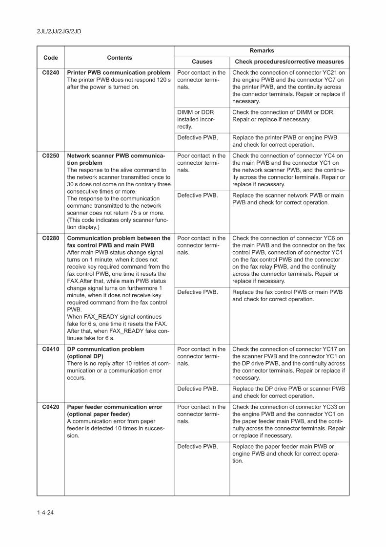
C0240 Printer PWB communication problemThe printer PWB does not respond 120 s after the power is turned on.
Poor contact in the connector termi-nals.
Check the connection of connector YC21 on the engine PWB and the connector YC7 on the printer PWB, and the continuity across the connector terminals. Repair or replace if necessary.
DIMM or DDR installed incor-rectly.
Check the connection of DIMM or DDR. Repair or replace if necessary.
Defective PWB. Replace the printer PWB or engine PWB and check for correct operation.
C0250 Network scanner PWB communica-tion problemThe response to the alive command to the network scanner transmitted once to 30 s does not come on the contrary three consecutive times or more.The response to the communication command transmitted to the network scanner does not return 75 s or more. (This code indicates only scanner func-tion display.)
Poor contact in the connector termi-nals.
Check the connection of connector YC4 on the main PWB and the connector YC1 on the network scanner PWB, and the continu-ity across the connector terminals. Repair or replace if necessary.
Defective PWB. Replace the scanner network PWB or main PWB and check for correct operation.
C0280 Communication problem between the fax control PWB and main PWBAfter main PWB status change signal turns on 1 minute, when it does not receive key required command from the fax control PWB, one time it resets the FAX.After that, while main PWB status change signal turns on furthermore 1 minute, when it does not receive key required command from the fax control PWB.When FAX_READY signal continues fake for 6 s, one time it resets the FAX. After that, when FAX_READY fake con-tinues fake for 6 s.
Poor contact in the connector termi-nals.
Check the connection of connector YC6 on the main PWB and the connector on the fax control PWB, connection of connector YC1 on the fax control PWB and the connector on the fax relay PWB, and the continuity across the connector terminals. Repair or replace if necessary.
Defective PWB. Replace the fax control PWB or main PWB and check for correct operation.
C0410 DP communication problem(optional DP)There is no reply after 10 retries at com-munication or a communication error occurs.
Poor contact in the connector termi-nals.
Check the connection of connector YC17 on the scanner PWB and the connector YC1 on the DP drive PWB, and the continuity across the connector terminals. Repair or replace if necessary.
Defective PWB. Replace the DP drive PWB or scanner PWB and check for correct operation.
C0420 Paper feeder communication error (optional paper feeder)A communication error from paper feeder is detected 10 times in succes-sion.
Poor contact in the connector termi-nals.
Check the connection of connector YC33 on the engine PWB and the connector YC1 on the paper feeder main PWB, and the conti-nuity across the connector terminals. Repair or replace if necessary.
Defective PWB. Replace the paper feeder main PWB or engine PWB and check for correct opera-tion.
Code ContentsRemarks
Causes Check procedures/corrective measures

2JL/2JJ/2JG/2JD
1-4-25
C0440 Document finisher communication problem (optional document finisher)A communication error from document finisher is detected 10 times in succes-sion.
Poor contact in the connector termi-nals.
Check the connection of connector YC33 on the engine PWB and the connector on the finisher main PWB, and the continuity across the connector terminals. Repair or replace if necessary.
Defective PWB. Replace the finisher main PWB or engine PWB and check for correct operation.
C0610 Bitmap problemThe DIMM on the main PWB does not operate correctly.
Defective main PWB.
Replace the main PWB and check for cor-rect operation.
DDR on the main PWB installed incorrectly.
Check the connection. Repair or replace if necessary.
C0630 DMA problemDMA transmission of compressed, decompressed, rotated, relocated or blanked-out image data does not com-plete within the specified period of time.
Defective main PWB.
Replace the main PWB and check for cor-rect operation.
DDR on the main PWB installed incorrectly.
Check the connection. Repair or replace if necessary.
C0640 Hard disk drive problemThe hard disk cannot be accessed.
Poor contact in the connector termi-nals.
Check the connection of connector YC11 on the main PWB and the connector on the hard disk, and the continuity across the con-nector terminals. Repair or replace if neces-sary.
Defective hard disk.
Run U024 (HDD formatting) without turning the power off to initialize the hard disk (see page 1-3-11). Replace the hard disk drive and check for correct operation if the prob-lem is still detected after initialization.
Defective main PWB.
Replace the main PWB and check for cor-rect operation.
C0820 Fax control PWB CG ROM checksum error (optional fax)A checksum error occurred with the CG ROM data of the fax control PWB.
Defective fax soft-ware.
Install the fax software.
Defective fax con-trol PWB.
Replace the fax control PWB and verify the operation.
C0830 Fax control PWB flash program area checksum error (optional fax)A checksum error occurred with the pro-gram of the fax control PWB.
Defective fax soft-ware.
Install the fax software.
Defective fax con-trol PWB.
Replace the fax control PWB and verify the operation.
C0840 Faults of RTCThe time is judged to go back based on the comparison of the RTC time and the current time or five years or more have passed.
Defective main PWB.
Replace the main PWB and check for cor-rect operation.
The battery is dis-connected from the main PWB.
Check visually and remedy if necessary.
C0860 Fax control PWB software switch checksum error (optional fax)A checksum error occurred with the soft-ware switch value of the fax control PWB.
Defective fax soft-ware.
Install the fax software.
Defective fax con-trol PWB.
Replace the fax control PWB and verify the operation.
Code ContentsRemarks
Causes Check procedures/corrective measures

2JL/2JJ/2JG/2JD
1-4-26
C0870 Fax control PWB to main PWB high capacity data transfer problemHigh-capacity data transfer between the fax control PWB and the scanner MIP PWB was not normally performed even if the data transfer was retried 10 times.
Poor contact in the connector termi-nals.
Check the connection of connector YC6 on the main PWB and the connector on the fax control PWB, and the continuity across the connector terminals. Repair or replace if necessary.
Defective PWB. Replace the fax control PWB or main PWB and check for correct operation.
C0880 Program archive problem (optional fax)When power is turned on, the com-pressed program in the Flash ROM on the fax control PWB was not success-fully decompressed.
Defective fax soft-ware.
Install the fax software.
Defective fax con-trol PWB.
Replace the fax control PWB and verify the operation.
C0890 Fax control PWB CG FONT archive problem (optional fax)When power is turned on, the com-pressed CG font in the Flash ROM on the fax control PWB was not success-fully decompressed.
Defective fax soft-ware.
Install the fax software.
Defective fax con-trol PWB.
Replace the fax control PWB and verify the operation.
C0920 Fax file system errorThe backup data is not retained for file system abnormality of flash memory of the fax control PWB.
Defective fax con-trol PWB.
Replace the fax control PWB and verify the operation.
C1010 Lift motor 1 errorWhen cassette 1 is inserted, lift limit switch 1 does not turn on within 12 s of lift motor 1 turning on.
Poor contact in the connector termi-nals.
Check the connection of connector of lift motor 1 and the connector YC25 on the engine PWB, and the continuity across the connector terminals. Repair or replace if necessary.
Broken gears or couplings of lift motor 1.
Replace lift motor 1.
Defective lift motor 1.
Check for continuity across the coil. If none, replace lift motor 1.
Defective lift switch 1.
Check if YC9-12 on the feed PWB goes low when lift switch 1 is turned off. If not, replace lift switch 1.
Poor contact in the connector termi-nals.
Check the connection of connector of lift switch 1 and the connector YC9 on the feed PWB, and the continuity across the connec-tor terminals. Repair or replace if necessary.
Defective PWB. Replace the feed PWB or engine PWB and check for correct operation.
Code ContentsRemarks
Causes Check procedures/corrective measures

2JL/2JJ/2JG/2JD
1-4-27
C1020 Lift motor 2 errorWhen cassette 2 is inserted, lift limit switch 2 does not turn on within 12 s of lift motor 2 turning on.
Poor contact in the connector termi-nals.
Check the connection of connector of lift motor 2 and the connector YC25 on the engine PWB, and the continuity across the connector terminals. Repair or replace if necessary.
Broken gears or couplings of lift motor 2.
Replace lift motor 2.
Defective lift motor 2.
Check for continuity across the coil. If none, replace lift motor 2.
Defective lift switch 2.
Check if YC9-6 on the feed PWB goes low when lift switch 2 is turned off. If not, replace lift switch 2.
Poor contact in the connector termi-nals.
Check the connection of connector of lift switch 2 and the connector YC9 on the feed PWB, and the continuity across the connec-tor terminals. Repair or replace if necessary.
Defective PWB. Replace the feed PWB or engine PWB and check for correct operation.
C1030 Paper feeder lift motor 1 error (optional paper feeder)When optional cassette 3 is inserted, paper feeder lift switch 1 does not turn on within 12 s of paper feeder lift motor 1 turning on.The lift overcurrent protective monitor signal is detected above 500 ms during driving the motor.However, the first 1 s after paper feeder lift motor 1 is turned on is excluded from detection.
Poor contact in the connector termi-nals.
Check the connection of connector on the engine PWB and the connector on the paper feeder main PWB, and the continuity across the connector terminals. Repair or replace if necessary.
Broken gears or couplings of paper feeder lift motor 1.
Replace paper feeder lift motor 1.
Defective paper feeder lift motor 1.
Check for continuity across the coil. If none, replace paper feeder lift motor 1.
Defective paper feeder lift switch 1.
Check if YC1-5 on the paper feeder main PWB goes low when paper feeder lift switch 1 is turned off. If not, replace paper feeder lift switch 1.
C1040 Paper feeder lift motor 2 error (optional paper feeder)When optional cassette 4 is inserted, paper feeder lift switch 2 does not turn on within 12 s of paper feeder lift motor 2 turning on.The lift overcurrent protective monitor signal is detected above 500 ms during driving the motor.However, the first 1 s after paper feeder lift motor 2 is turned on is excluded from detection.
Poor contact in the connector termi-nals.
Check the connection of connector on the engine PWB and the connector on the paper feeder main PWB, and the continuity across the connector terminals. Repair or replace if necessary.
Broken gears or couplings of paper feeder lift motor 2.
Replace paper feeder lift motor 2.
Defective paper feeder lift motor 2.
Check for continuity across the coil. If none, replace paper feeder lift motor 2.
Defective paper feeder lift switch 2.
Check if YC1-7 on the paper feeder main PWB goes low when paper feeder lift switch 2 is turned off. If not, replace paper feeder lift switch 2.
Code ContentsRemarks
Causes Check procedures/corrective measures

2JL/2JJ/2JG/2JD
1-4-28
C1100 Paper feeder lift motor 1 error (optional 3000-sheet paper feeder)A motor over-current signal is detected continuously for 1 s or longer.
Poor contact in the connector termi-nals.
Check the connection of connector on the engine PWB and the connector on the paper feeder main PWB, and the continuity across the connector terminals. Repair or replace if necessary.
Paper feeder lift motor 1 does not rotate correctly (the motor is over-loaded).
Check the gears and remedy if necessary.
C1110 Paper feeder lift motor 2 error (optional 3000-sheet paper feeder)A motor over-current signal is detected continuously for 1 s or longer.
Poor contact in the connector termi-nals.
Check the connection of connector on the engine PWB and the connector on the paper feeder main PWB, and the continuity across the connector terminals. Repair or replace if necessary.
Paper feeder lift motor 2 does not rotate correctly (the motor is over-loaded).
Check the gears and remedy if necessary.
C1120 Paper feeder left lift position problem (optional 3000-sheet paper feeder)Paper feeder switch 1 does not turn on within 30 s of paper feeder lift motor 2 turning on.
Poor contact in the connector termi-nals.
Check the connection of connector on the engine PWB and the connector on the paper feeder main PWB, and the continuity across the connector terminals. Repair or replace if necessary.
Defective paper feeder lift switch 1.
Check if YC5-4 on the paper feeder main PWB goes low when paper feeder lift switch 1 is turned off. If not, replace paper feeder lift switch 1.
Defective paper feeder lift motor 2.
Check for continuity across the coil. If none, replace paper feeder lift motor 2.
The paper feeder left lift does not rise properly.
Check the gears and belts, and remedy if necessary.
C1130 Paper feeder right lift position prob-lem (optional 3000-sheet paper feeder)Paper feeder switch 2 does not turn on within 30 s of paper feeder lift motor 1 turning on.
Poor contact in the connector termi-nals.
Check the connection of connector on the engine PWB and the connector on the paper feeder main PWB, and the continuity across the connector terminals. Repair or replace if necessary.
Defective paper feeder lift switch 2.
Check if YC5-7 on the paper feeder main PWB goes low when paper feeder lift switch 2 is turned off. If not, replace paper feeder lift switch 2.
Defective paper feeder lift motor 1.
Check for continuity across the coil. If none, replace paper feeder lift motor 1.
The paper feeder right lift does not rise properly.
Check the gears and belts, and remedy if necessary.
Code ContentsRemarks
Causes Check procedures/corrective measures
2JL/2JJ/2JG/2JD
1-4-29
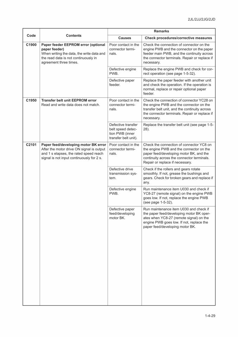
C1900 Paper feeder EEPROM error (optional paper feeder)When writing the data, the write data and the read data is not continuously in agreement three times.
Poor contact in the connector termi-nals.
Check the connection of connector on the engine PWB and the connector on the paper feeder main PWB, and the continuity across the connector terminals. Repair or replace if necessary.
Defective engine PWB.
Replace the engine PWB and check for cor-rect operation (see page 1-5-32).
Defective paper feeder.
Replace the paper feeder with another unit and check the operation. If the operation is normal, replace or repair optional paper feeder.
C1950 Transfer belt unit EEPROM errorRead and write data does not match.
Poor contact in the connector termi-nals.
Check the connection of connector YC28 on the engine PWB and the connector on the transfer belt unit, and the continuity across the connector terminals. Repair or replace if necessary.
Defective transfer belt speed detec-tion PWB (inner transfer belt unit).
Replace the transfer belt unit (see page 1-5-28).
C2101 Paper feed/developing motor BK errorAfter the motor drive ON signal is output and 1 s elapses, the rated speed reach signal is not input continuously for 2 s.
Poor contact in the connector termi-nals.
Check the connection of connector YC8 on the engine PWB and the connector on the paper feed/developing motor BK, and the continuity across the connector terminals. Repair or replace if necessary.
Defective drive transmission sys-tem.
Check if the rollers and gears rotate smoothly. If not, grease the bushings and gears. Check for broken gears and replace if any.
Defective engine PWB.
Run maintenance item U030 and check if YC8-27 (remote signal) on the engine PWB goes low. If not, replace the engine PWB (see page 1-5-32).
Defective paper feed/developing motor BK.
Run maintenance item U030 and check if the paper feed/developing motor BK oper-ates when YC8-27 (remote signal) on the engine PWB goes low. If not, replace the paper feed/developing motor BK.
Code ContentsRemarks
Causes Check procedures/corrective measures
2JL/2JJ/2JG/2JD
1-4-30
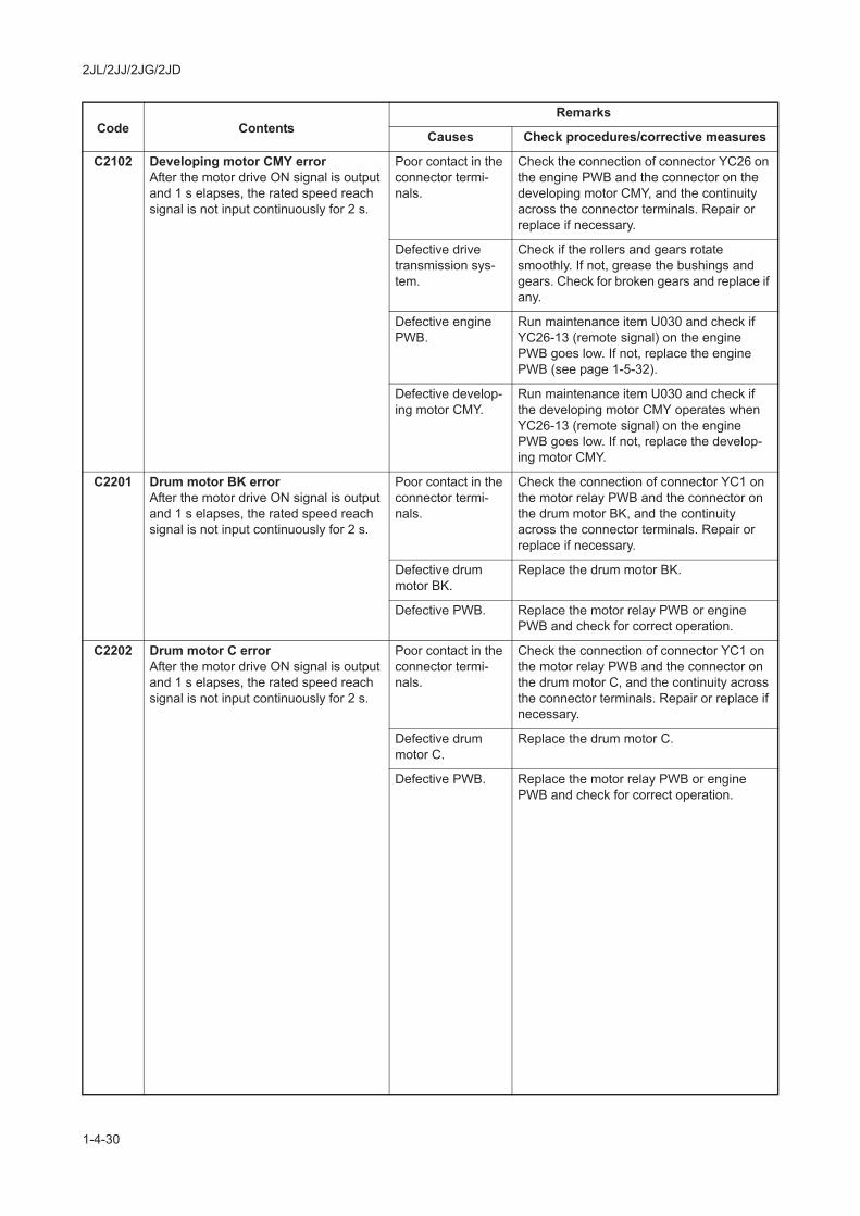
C2102 Developing motor CMY errorAfter the motor drive ON signal is output and 1 s elapses, the rated speed reach signal is not input continuously for 2 s.
Poor contact in the connector termi-nals.
Check the connection of connector YC26 on the engine PWB and the connector on the developing motor CMY, and the continuity across the connector terminals. Repair or replace if necessary.
Defective drive transmission sys-tem.
Check if the rollers and gears rotate smoothly. If not, grease the bushings and gears. Check for broken gears and replace if any.
Defective engine PWB.
Run maintenance item U030 and check if YC26-13 (remote signal) on the engine PWB goes low. If not, replace the engine PWB (see page 1-5-32).
Defective develop-ing motor CMY.
Run maintenance item U030 and check if the developing motor CMY operates when YC26-13 (remote signal) on the engine PWB goes low. If not, replace the develop-ing motor CMY.
C2201 Drum motor BK errorAfter the motor drive ON signal is output and 1 s elapses, the rated speed reach signal is not input continuously for 2 s.
Poor contact in the connector termi-nals.
Check the connection of connector YC1 on the motor relay PWB and the connector on the drum motor BK, and the continuity across the connector terminals. Repair or replace if necessary.
Defective drum motor BK.
Replace the drum motor BK.
Defective PWB. Replace the motor relay PWB or engine PWB and check for correct operation.
C2202 Drum motor C errorAfter the motor drive ON signal is output and 1 s elapses, the rated speed reach signal is not input continuously for 2 s.
Poor contact in the connector termi-nals.
Check the connection of connector YC1 on the motor relay PWB and the connector on the drum motor C, and the continuity across the connector terminals. Repair or replace if necessary.
Defective drum motor C.
Replace the drum motor C.
Defective PWB. Replace the motor relay PWB or engine PWB and check for correct operation.
Code ContentsRemarks
Causes Check procedures/corrective measures

2JL/2JJ/2JG/2JD
1-4-31
C2203 Drum motor M errorAfter the motor drive ON signal is output and 1 s elapses, the rated speed reach signal is not input continuously for 2 s.
Poor contact in the connector termi-nals.
Check the connection of connector YC1 on the motor relay PWB and the connector on the drum motor M, and the continuity across the connector terminals. Repair or replace if necessary.
Defective drum motor M.
Replace the drum motor M.
Defective PWB. Replace the motor relay PWB or engine PWB and check for correct operation.
C2204 Drum motor Y errorAfter the motor drive ON signal is output and 1 s elapses, the rated speed reach signal is not input continuously for 2 s.
Poor contact in the connector termi-nals.
Check the connection of connector YC1 on the motor relay PWB and the connector on the drum motor Y, and the continuity across the connector terminals. Repair or replace if necessary.
Defective drum motor Y.
Replace the drum motor Y.
Defective PWB. Replace the motor relay PWB or engine PWB and check for correct operation.
C2300 Fuser motor errorAfter the motor drive ON signal is output and 1 s elapses, the rated speed reach signal is not input continuously for 2 s.
Poor contact in the connector termi-nals.
Check the connection of connector YC27 on the engine PWB and the connector on the fuser motor, and the continuity across the connector terminals. Repair or replace if necessary.
Defective drive transmission sys-tem.
Check if the rollers and gears rotate smoothly. If not, grease the bushings and gears. Check for broken gears and replace if any.
Defective engine PWB.
Run maintenance item U030 and check if YC27-A10 (remote signal) on the engine PWB goes low. If not, replace the engine PWB (see page 1-5-32).
Defective fuser motor.
Run maintenance item U030 and check if the fuser motor operates when YC27-A10 (remote signal) on the engine PWB goes low. If not, replace the fuser motor.
Code ContentsRemarks
Causes Check procedures/corrective measures

2JL/2JJ/2JG/2JD
1-4-32
C2400 Eject motor errorAfter the motor drive ON signal is output and 1 s elapses, the rated speed reach signal is not input continuously for 2 s.
Poor contact in the connector termi-nals.
Check the connection of connector YC27 on the engine PWB and the connector on the eject motor, and the continuity across the connector terminals. Repair or replace if necessary.
Defective drive transmission sys-tem.
Check if the rollers and gears rotate smoothly. If not, grease the bushings and gears. Check for broken gears and replace if any.
Defective engine PWB.
Run maintenance item U030 and check if YC27-B4 (remote signal) on the engine PWB goes low. If not, replace the engine PWB (see page 1-5-32).
Defective eject motor.
Run maintenance item U030 and check if the eject motor operates when YC27-B4 (remote signal) on the engine PWB goes low. If not, replace the eject motor.
C2500 MP motor errorAfter the motor drive ON signal is output and 1 s elapses, the rated speed reach signal is not input continuously for 2 s.
Poor contact in the connector termi-nals.
Check the connection of connector YC26 on the engine PWB and the connector on the MP motor, and the continuity across the con-nector terminals. Repair or replace if neces-sary.
Defective drive transmission sys-tem.
Check if the rollers and gears rotate smoothly. If not, grease the bushings and gears. Check for broken gears and replace if any.
Defective engine PWB.
Run maintenance item U030 and check if YC26-5 (remote signal) on the engine PWB goes low. If not, replace the engine PWB (see page 1-5-32).
Defective MP motor.
Run maintenance item U030 and check if the MP motor operates when YC26-5 (remote signal) on the engine PWB goes low. If not, replace the MP motor.
C2600 Paper feeder paper conveying motor error (optional paper feeder)The lock signal of the motor is detected above 450 ms.
Poor contact in the connector termi-nals.
Check the connection of connector on the engine PWB and the connector on the paper feeder main PWB, and the continuity across the connector terminals. Repair or replace if necessary.
Defective drive transmission sys-tem.
Check if the rollers and gears rotate smoothly. If not, grease the bushings and gears. Check for broken gears and replace if any.
Defective PWB. Replace the paper feeder main PWB or engine PWB and check for correct opera-tion.
Defective paper feeder paper con-veying motor.
Replace the paper feeder paper conveying motor.
Code ContentsRemarks
Causes Check procedures/corrective measures
2JL/2JJ/2JG/2JD
1-4-33
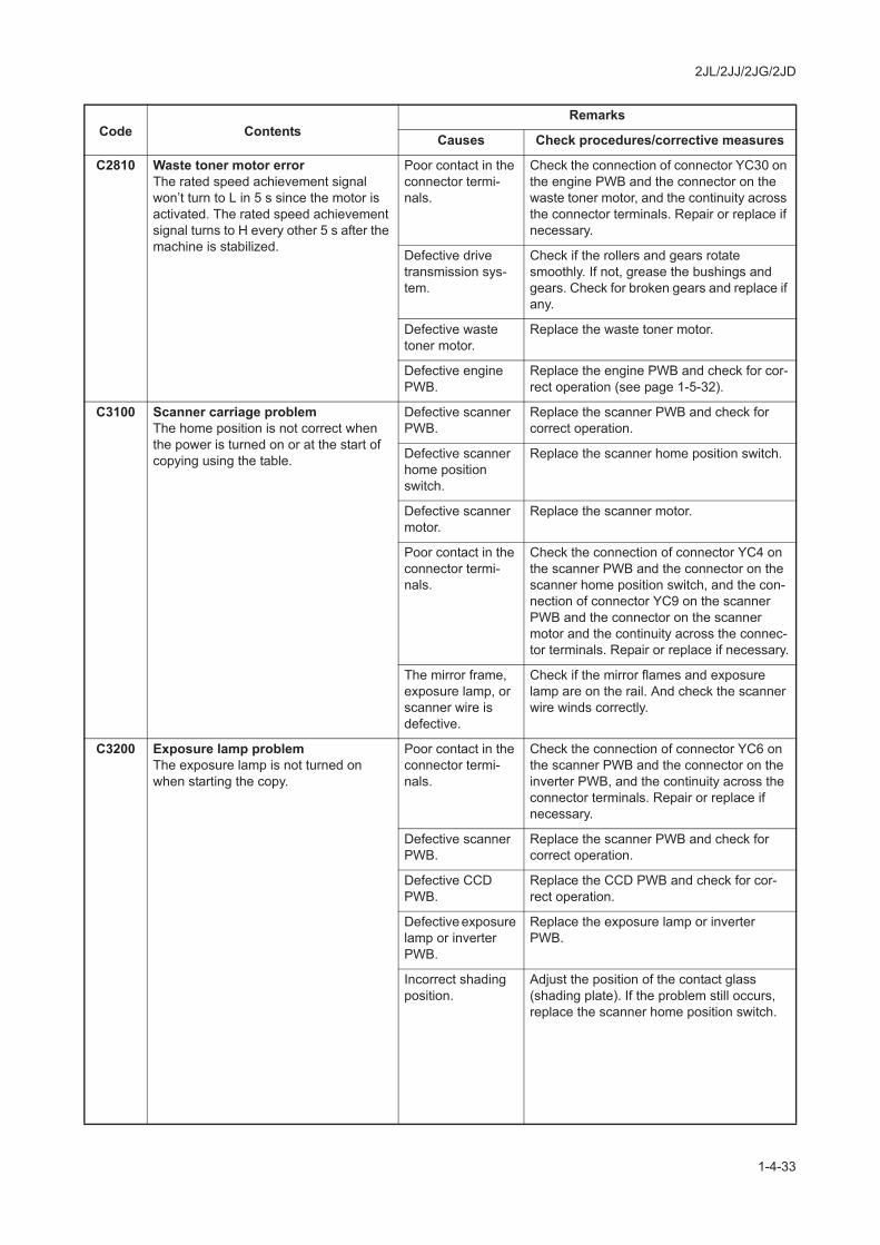
C2810 Waste toner motor errorThe rated speed achievement signal won’t turn to L in 5 s since the motor is activated. The rated speed achievement signal turns to H every other 5 s after the machine is stabilized.
Poor contact in the connector termi-nals.
Check the connection of connector YC30 on the engine PWB and the connector on the waste toner motor, and the continuity across the connector terminals. Repair or replace if necessary.
Defective drive transmission sys-tem.
Check if the rollers and gears rotate smoothly. If not, grease the bushings and gears. Check for broken gears and replace if any.
Defective waste toner motor.
Replace the waste toner motor.
Defective engine PWB.
Replace the engine PWB and check for cor-rect operation (see page 1-5-32).
C3100 Scanner carriage problemThe home position is not correct when the power is turned on or at the start of copying using the table.
Defective scanner PWB.
Replace the scanner PWB and check for correct operation.
Defective scanner home position switch.
Replace the scanner home position switch.
Defective scanner motor.
Replace the scanner motor.
Poor contact in the connector termi-nals.
Check the connection of connector YC4 on the scanner PWB and the connector on the scanner home position switch, and the con-nection of connector YC9 on the scanner PWB and the connector on the scanner motor and the continuity across the connec-tor terminals. Repair or replace if necessary.
The mirror frame, exposure lamp, or scanner wire is defective.
Check if the mirror flames and exposure lamp are on the rail. And check the scanner wire winds correctly.
C3200 Exposure lamp problemThe exposure lamp is not turned on when starting the copy.
Poor contact in the connector termi-nals.
Check the connection of connector YC6 on the scanner PWB and the connector on the inverter PWB, and the continuity across the connector terminals. Repair or replace if necessary.
Defective scanner PWB.
Replace the scanner PWB and check for correct operation.
Defective CCD PWB.
Replace the CCD PWB and check for cor-rect operation.
Defective exposure lamp or inverter PWB.
Replace the exposure lamp or inverter PWB.
Incorrect shading position.
Adjust the position of the contact glass (shading plate). If the problem still occurs, replace the scanner home position switch.
Code ContentsRemarks
Causes Check procedures/corrective measures
2JL/2JJ/2JG/2JD
1-4-34
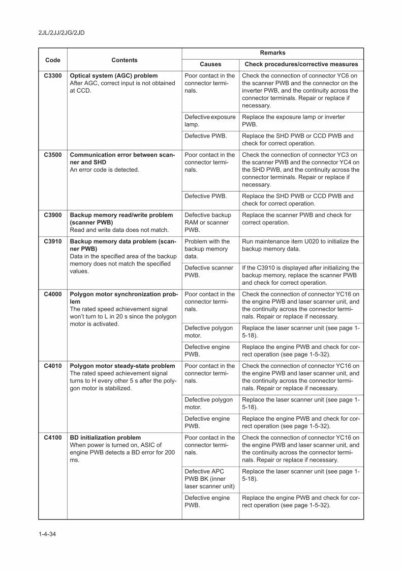
C3300 Optical system (AGC) problemAfter AGC, correct input is not obtained at CCD.
Poor contact in the connector termi-nals.
Check the connection of connector YC6 on the scanner PWB and the connector on the inverter PWB, and the continuity across the connector terminals. Repair or replace if necessary.
Defective exposure lamp.
Replace the exposure lamp or inverter PWB.
Defective PWB. Replace the SHD PWB or CCD PWB and check for correct operation.
C3500 Communication error between scan-ner and SHDAn error code is detected.
Poor contact in the connector termi-nals.
Check the connection of connector YC3 on the scanner PWB and the connector YC4 on the SHD PWB, and the continuity across the connector terminals. Repair or replace if necessary.
Defective PWB. Replace the SHD PWB or CCD PWB and check for correct operation.
C3900 Backup memory read/write problem (scanner PWB)Read and write data does not match.
Defective backup RAM or scanner PWB.
Replace the scanner PWB and check for correct operation.
C3910 Backup memory data problem (scan-ner PWB)Data in the specified area of the backup memory does not match the specified values.
Problem with the backup memory data.
Run maintenance item U020 to initialize the backup memory data.
Defective scanner PWB.
If the C3910 is displayed after initializing the backup memory, replace the scanner PWB and check for correct operation.
C4000 Polygon motor synchronization prob-lemThe rated speed achievement signal won’t turn to L in 20 s since the polygon motor is activated.
Poor contact in the connector termi-nals.
Check the connection of connector YC16 on the engine PWB and laser scanner unit, and the continuity across the connector termi-nals. Repair or replace if necessary.
Defective polygon motor.
Replace the laser scanner unit (see page 1-5-18).
Defective engine PWB.
Replace the engine PWB and check for cor-rect operation (see page 1-5-32).
C4010 Polygon motor steady-state problemThe rated speed achievement signal turns to H every other 5 s after the poly-gon motor is stabilized.
Poor contact in the connector termi-nals.
Check the connection of connector YC16 on the engine PWB and laser scanner unit, and the continuity across the connector termi-nals. Repair or replace if necessary.
Defective polygon motor.
Replace the laser scanner unit (see page 1-5-18).
Defective engine PWB.
Replace the engine PWB and check for cor-rect operation (see page 1-5-32).
C4100 BD initialization problemWhen power is turned on, ASIC of engine PWB detects a BD error for 200 ms.
Poor contact in the connector termi-nals.
Check the connection of connector YC16 on the engine PWB and laser scanner unit, and the continuity across the connector termi-nals. Repair or replace if necessary.
Defective APC PWB BK (inner laser scanner unit)
Replace the laser scanner unit (see page 1-5-18).
Defective engine PWB.
Replace the engine PWB and check for cor-rect operation (see page 1-5-32).
Code ContentsRemarks
Causes Check procedures/corrective measures
2JL/2JJ/2JG/2JD
1-4-35
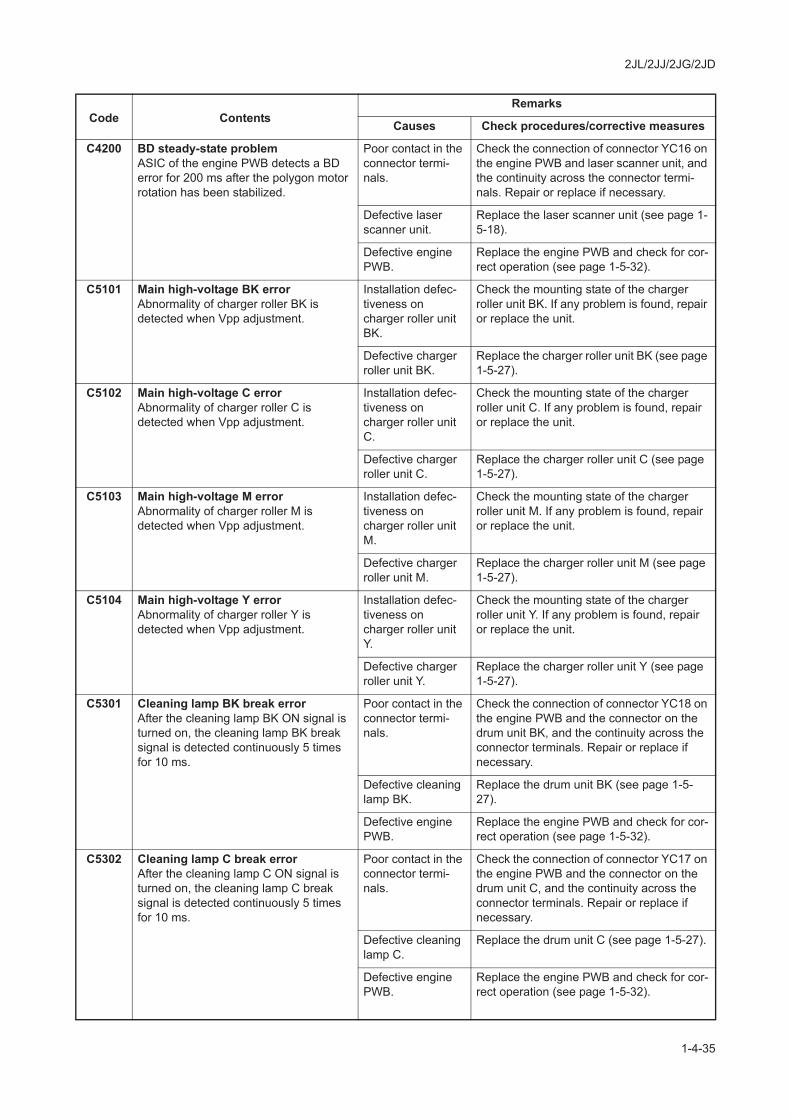
C4200 BD steady-state problemASIC of the engine PWB detects a BD error for 200 ms after the polygon motor rotation has been stabilized.
Poor contact in the connector termi-nals.
Check the connection of connector YC16 on the engine PWB and laser scanner unit, and the continuity across the connector termi-nals. Repair or replace if necessary.
Defective laser scanner unit.
Replace the laser scanner unit (see page 1-5-18).
Defective engine PWB.
Replace the engine PWB and check for cor-rect operation (see page 1-5-32).
C5101 Main high-voltage BK errorAbnormality of charger roller BK is detected when Vpp adjustment.
Installation defec-tiveness on charger roller unit BK.
Check the mounting state of the charger roller unit BK. If any problem is found, repair or replace the unit.
Defective charger roller unit BK.
Replace the charger roller unit BK (see page 1-5-27).
C5102 Main high-voltage C errorAbnormality of charger roller C is detected when Vpp adjustment.
Installation defec-tiveness on charger roller unit C.
Check the mounting state of the charger roller unit C. If any problem is found, repair or replace the unit.
Defective charger roller unit C.
Replace the charger roller unit C (see page 1-5-27).
C5103 Main high-voltage M errorAbnormality of charger roller M is detected when Vpp adjustment.
Installation defec-tiveness on charger roller unit M.
Check the mounting state of the charger roller unit M. If any problem is found, repair or replace the unit.
Defective charger roller unit M.
Replace the charger roller unit M (see page 1-5-27).
C5104 Main high-voltage Y errorAbnormality of charger roller Y is detected when Vpp adjustment.
Installation defec-tiveness on charger roller unit Y.
Check the mounting state of the charger roller unit Y. If any problem is found, repair or replace the unit.
Defective charger roller unit Y.
Replace the charger roller unit Y (see page 1-5-27).
C5301 Cleaning lamp BK break errorAfter the cleaning lamp BK ON signal is turned on, the cleaning lamp BK break signal is detected continuously 5 times for 10 ms.
Poor contact in the connector termi-nals.
Check the connection of connector YC18 on the engine PWB and the connector on the drum unit BK, and the continuity across the connector terminals. Repair or replace if necessary.
Defective cleaning lamp BK.
Replace the drum unit BK (see page 1-5-27).
Defective engine PWB.
Replace the engine PWB and check for cor-rect operation (see page 1-5-32).
C5302 Cleaning lamp C break errorAfter the cleaning lamp C ON signal is turned on, the cleaning lamp C break signal is detected continuously 5 times for 10 ms.
Poor contact in the connector termi-nals.
Check the connection of connector YC17 on the engine PWB and the connector on the drum unit C, and the continuity across the connector terminals. Repair or replace if necessary.
Defective cleaning lamp C.
Replace the drum unit C (see page 1-5-27).
Defective engine PWB.
Replace the engine PWB and check for cor-rect operation (see page 1-5-32).
Code ContentsRemarks
Causes Check procedures/corrective measures

2JL/2JJ/2JG/2JD
1-4-36
C5303 Cleaning lamp M break errorAfter the cleaning lamp M ON signal is turned on, the cleaning lamp M break signal is detected continuously 5 times for 10 ms.
Poor contact in the connector termi-nals.
Check the connection of connector YC17 on the engine PWB and the connector on the drum unit M, and the continuity across the connector terminals. Repair or replace if necessary.
Defective cleaning lamp M.
Replace the drum unit M (see page 1-5-27).
Defective engine PWB.
Replace the engine PWB and check for cor-rect operation (see page 1-5-32).
C5304 Cleaning lamp Y break errorAfter the cleaning lamp Y ON signal is turned on, the cleaning lamp Y break signal is detected continuously 5 times for 10 ms.
Poor contact in the connector termi-nals.
Check the connection of connector YC18 on the engine PWB and the connector on the drum unit Y, and the continuity across the connector terminals. Repair or replace if necessary.
Defective cleaning lamp Y.
Replace the drum unit Y (see page 1-5-27).
Defective engine PWB.
Replace the engine PWB and check for cor-rect operation (see page 1-5-32).
C6000 Fuser heater 1/2 breakFuser thermistor 1 detected less than 75 C/167 F for 30 s during warming up.
Fuser thermistor 1 deduced 40 C/104 F or more for 5 s during warming up.
Fuser thermistor 3 deduced less than 90 C/194 F for 30 s during warming up.
Fuser thermistor 3 deduced less than 160 C/320 F for 90 s during warming up.Fuser thermistor 3 deduced less than 140 C/284 F for 5 s during stand-by.
Defective fuser heater 1/2.
Check for continuity across each heater. If none, replace the fuser unit (see page 1-5-31).
Defective fuser thermostat 1.
Check for continuity across thermostat. If none, remove the cause and replace the fuser unit (see page 1-5-31).
Installation defec-tiveness on fuser thermistor 1/2.
Measure the resistance. If it is , replace the fuser unit (see page 1-5-31).
Defective PWB. Replace the power source PWB or engine PWB and check for correct operation.
C6010 Abnormally high fuser thermistor temperatureThe fuser Abnormally high signal is detected for 60 s or more.
Defective PWB. Replace the power source PWB or engine PWB and check for correct operation.
C6020 Abnormally high fuser thermistor 1/3 temperatureThe fuser temperature exceeds 240 C/464 F.
Defective PWB. Replace the power source PWB or engine PWB and check for correct operation.
Installation defec-tiveness on fuser thermistor 1/3.
Measure the resistance. If it is , replace the fuser unit (see page 1-5-31).
C6030 Fuser thermistor 1/3 break errorFuser thermistor 1 detected 40 C/104 F or less during warming up.
40 C/104 F or less is detected between 10 s of continuation during warming up.Fuser thermistor 3 detected 40 C/104 F or less during warming up.
Defective fuser heater 1/2.
Check for continuity across each heater. If none, replace the fuser unit (see page 1-5-31).
Installation defec-tiveness on fuser thermistor 1/3.
Measure the resistance. If it is , replace the fuser unit (see page 1-5-31).
Defective PWB. Replace the power source PWB or engine PWB and check for correct operation.
C6050 Abnormally low fuser thermistor 3 temperatureDuring copying, the temperature at the heat roller lower than 100 C/212 F is detected continuously for 1 s.
Defective fuser heater 1/2.
Replace the fuser unit (see page 1-5-31).
Defective PWB. Replace the power source PWB or engine PWB and check for correct operation.
Code ContentsRemarks
Causes Check procedures/corrective measures

2JL/2JJ/2JG/2JD
1-4-37
C6100 Fuser heater 3 breakFuser thermistor 2 detected less than 100 C/212 F for 120 s during driving.Fuser thermistor 2 deduced less than 150 C/302 F for 300 s during driving.Fuser thermistor 2 deduced less than 100 C/212 F for 5 s during driving.
Defective fuser heater 3.
Check for continuity across each heater. If none, replace the fuser unit (see page 1-5-31).
Defective fuser thermostat 2.
Check for continuity across thermostat. If none, remove the cause and replace the fuser unit (see page 1-5-31).
Installation defec-tiveness on fuser thermistor 2.
Measure the resistance. If it is , replace the fuser unit (see page 1-5-31).
Defective PWB. Replace the power source PWB or engine PWB and check for correct operation.
C6120 Abnormally high fuser thermistor 2 temperatureThe fuser temperature exceeds 190 C/374 F.
Installation defec-tiveness on fuser thermistor 2.
Measure the resistance. If it is , replace the fuser unit (see page 1-5-31).
Defective PWB. Replace the power source PWB or engine PWB and check for correct operation.
C6130 Fuser thermistor 2 break errorFuser thermistor 2 detected less than 40 C/104 F during driving.
When the difference of temperature of fuser thermistor 1 and 3 becomes 100 C/212 F or more.
Installation defec-tiveness on fuser thermistor 2.
Measure the resistance. If it is , replace the fuser unit (see page 1-5-31).
Defective fuser heater 3.
Check for continuity across each heater. If none, replace the fuser unit (see page 1-5-31).
Defective PWB. Replace the power source PWB or engine PWB and check for correct operation.
C6400 Zero-cross signal errorWhile fuser heater ON/OFF control is performed, the zero-cross signal is not input within 3 s.
Defective PWB. Replace the engine PWB or power source PWB and check for correct operation.
C7000 Toner motor problemThe rated speed achievement signal won’t turn to L in 5 s since the motor is activated. The rated speed achievement signal turns to H every other 5 s after the machine is stabilized.
Poor contact in the connector termi-nals.
Check the connection of connector YC30 on the engine PWB and the connector on the toner motor, and the continuity across the connector terminals. Repair or replace if necessary.
Broken the gear. Check visually and replace the gear if nec-essary.
Defective toner motor M/C/Y/BK.
Run maintenance item U135 and check if the toner motor operates. If not, replace the toner motor.
Defective engine PWB.
Replace the engine PWB and check for cor-rect operation (see page 1-5-32).
C7101 Toner sensor BK problemSensor output value of 78 or less or 944 or more continued for 3 s.
Defective develop-ing unit BK.
Replace the developing unit BK (see page 1-5-26).
Defective engine PWB.
Replace the engine PWB and check for cor-rect operation (see page 1-5-32).
C7102 Toner sensor C problemSensor output value of 78 or less or 944 or more continued for 3 s.
Defective develop-ing unit C.
Replace the developing unit C (see page 1-5-26).
Defective engine PWB.
Replace the engine PWB and check for cor-rect operation (see page 1-5-32).
Code ContentsRemarks
Causes Check procedures/corrective measures

2JL/2JJ/2JG/2JD
1-4-38
C7103 Toner sensor M problemSensor output value of 78 or less or 944 or more continued for 3 s.
Defective develop-ing unit M.
Replace the developing unit M (see page 1-5-26).
Defective engine PWB.
Replace the engine PWB and check for cor-rect operation (see page 1-5-32).
C7104 Toner sensor Y problemSensor output value of 78 or less or 944 or more continued for 3 s.
Defective develop-ing unit Y.
Replace the developing unit Y (see page 1-5-26).
Defective engine PWB.
Replace the engine PWB and check for cor-rect operation (see page 1-5-32).
C7200 Broken internal thermistor wireAn abnormal value is detected in the input data to inner temperature sensor 1.
Poor contact in the connector termi-nals.
Check the connection of connector YC16 on the engine PWB and the continuity across the connector terminals. Repair or replace if necessary.
Defective laser scanner unit.
Replace the laser scanner unit (see page 1-5-18).
Defective engine PWB.
Replace the engine PWB and check for cor-rect operation (see page 1-5-32).
C7210 Short-circuited internal thermistorAn abnormal value is detected in the input data to inner temperature sensor 1.
Poor contact in the connector termi-nals.
Check the connection of connector YC16 on the engine PWB and the continuity across the connector terminals. Repair or replace if necessary.
Defective laser scanner unit.
Replace the laser scanner unit (see page 1-5-18).
Defective engine PWB.
Replace the engine PWB and check for cor-rect operation (see page 1-5-32).
C7220 Broken internal thermistor 2 wireAn abnormal value is detected in the input data to inner temperature sensor 2.
Poor contact in the connector termi-nals.
Check the connection of connector YC28 on the engine PWB and the continuity across the connector terminals. Repair or replace if necessary.
Defective engine PWB.
Replace the engine PWB and check for cor-rect operation (see page 1-5-32).
C7230 Short-circuited internal thermistor 2An abnormal value is detected in the input data to inner temperature sensor 2.
Poor contact in the connector termi-nals.
Check the connection of connector YC28 on the engine PWB and the continuity across the connector terminals. Repair or replace if necessary.
Defective engine PWB.
Replace the engine PWB and check for cor-rect operation (see page 1-5-32).
C7240 Broken internal thermistor 3 wireAn abnormal value is detected in the input data to inner temperature sensor 3.
Poor contact in the connector termi-nals.
Check the connection of connector YC8 on the engine PWB and the continuity across the connector terminals. Repair or replace if necessary.
Defective engine PWB.
Replace the engine PWB and check for cor-rect operation (see page 1-5-32).
C7250 Short-circuited internal thermistor 3An abnormal value is detected in the input data to inner temperature sensor 3.
Poor contact in the connector termi-nals.
Check the connection of connector YC8 on the engine PWB and the continuity across the connector terminals. Repair or replace if necessary.
Defective engine PWB.
Replace the engine PWB and check for cor-rect operation (see page 1-5-32).
Code ContentsRemarks
Causes Check procedures/corrective measures
2JL/2JJ/2JG/2JD
1-4-39
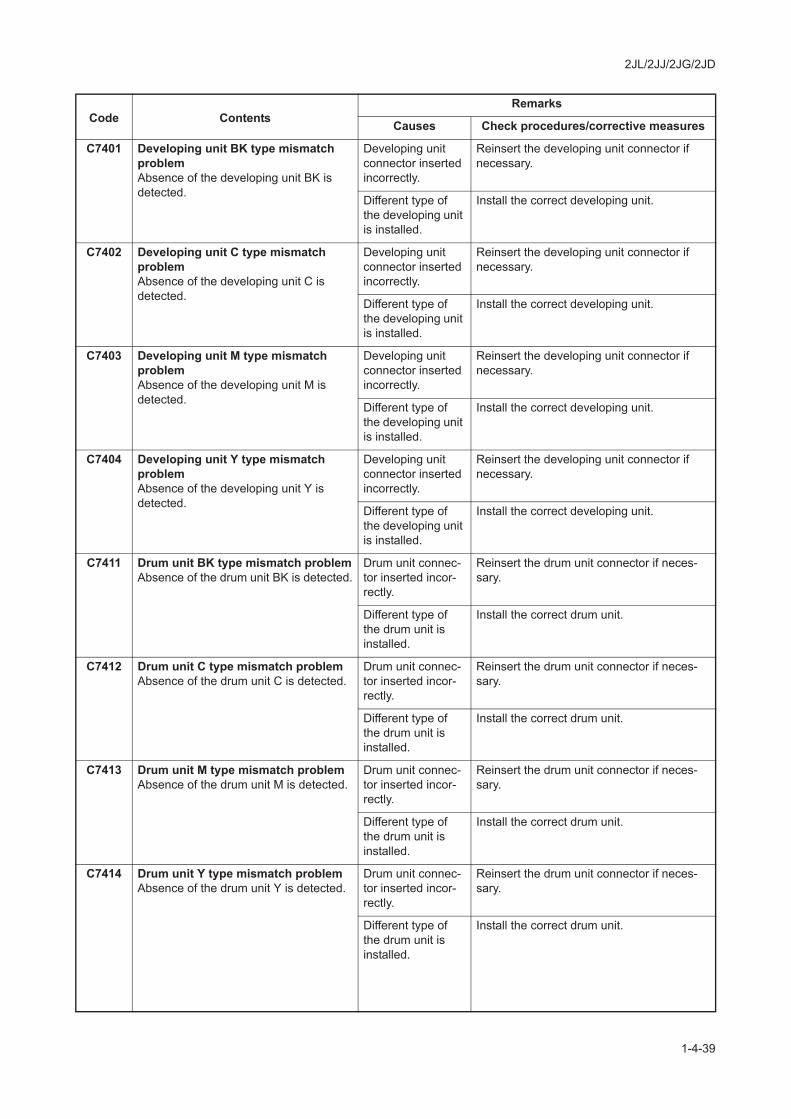
C7401 Developing unit BK type mismatch problemAbsence of the developing unit BK is detected.
Developing unit connector inserted incorrectly.
Reinsert the developing unit connector if necessary.
Different type of the developing unit is installed.
Install the correct developing unit.
C7402 Developing unit C type mismatch problemAbsence of the developing unit C is detected.
Developing unit connector inserted incorrectly.
Reinsert the developing unit connector if necessary.
Different type of the developing unit is installed.
Install the correct developing unit.
C7403 Developing unit M type mismatch problemAbsence of the developing unit M is detected.
Developing unit connector inserted incorrectly.
Reinsert the developing unit connector if necessary.
Different type of the developing unit is installed.
Install the correct developing unit.
C7404 Developing unit Y type mismatch problemAbsence of the developing unit Y is detected.
Developing unit connector inserted incorrectly.
Reinsert the developing unit connector if necessary.
Different type of the developing unit is installed.
Install the correct developing unit.
C7411 Drum unit BK type mismatch problemAbsence of the drum unit BK is detected.
Drum unit connec-tor inserted incor-rectly.
Reinsert the drum unit connector if neces-sary.
Different type of the drum unit is installed.
Install the correct drum unit.
C7412 Drum unit C type mismatch problemAbsence of the drum unit C is detected.
Drum unit connec-tor inserted incor-rectly.
Reinsert the drum unit connector if neces-sary.
Different type of the drum unit is installed.
Install the correct drum unit.
C7413 Drum unit M type mismatch problemAbsence of the drum unit M is detected.
Drum unit connec-tor inserted incor-rectly.
Reinsert the drum unit connector if neces-sary.
Different type of the drum unit is installed.
Install the correct drum unit.
C7414 Drum unit Y type mismatch problemAbsence of the drum unit Y is detected.
Drum unit connec-tor inserted incor-rectly.
Reinsert the drum unit connector if neces-sary.
Different type of the drum unit is installed.
Install the correct drum unit.
Code ContentsRemarks
Causes Check procedures/corrective measures

2JL/2JJ/2JG/2JD
1-4-40
C7420 Transfer belt unit type mismatch problemAbsence of the transfer belt unit is detected.
Transfer belt unit connector inserted incorrectly.
Reinsert the transfer belt unit connector if necessary.
Different type of the transfer belt unit is installed.
Install the correct transfer belt unit.
C7800 Broken external thermistor wireAn abnormal value is detected in the input data to the outer temperature sen-sor.
Poor contact in the connector termi-nals.
Check the connection of connector YC13 on the engine PWB and the continuity across the connector terminals. Repair or replace if necessary.
Defective engine PWB.
Replace the engine PWB and check for cor-rect operation (see page 1-5-32).
C7810 Short-circuited external thermistorAn abnormal value is detected in the input data to the outer temperature sen-sor.
Poor contact in the connector termi-nals.
Check the connection of connector YC13 on the engine PWB and the continuity across the connector terminals. Repair or replace if necessary.
Defective engine PWB.
Replace the engine PWB and check for cor-rect operation (see page 1-5-32).
C7901 Drum BK EEPROM errorReading from or writing to EEPROM cannot be performed.
Poor contact in the connector termi-nals.
Check the connection of connector YC18 on the engine PWB and the continuity across the connector terminals. Repair or replace if necessary.
Defective drum PWB BK.
Replace the drum unit BK (see page 1-5-27).
C7902 Drum C EEPROM errorReading from or writing to EEPROM cannot be performed.
Poor contact in the connector termi-nals.
Check the connection of connector YC17 on the engine PWB and the continuity across the connector terminals. Repair or replace if necessary.
Defective drum PWB C.
Replace the drum unit C (see page 1-5-27).
C7903 Drum M EEPROM errorReading from or writing to EEPROM cannot be performed.
Poor contact in the connector termi-nals.
Check the connection of connector YC17 on the engine PWB and the continuity across the connector terminals. Repair or replace if necessary.
Defective drum PWB M.
Replace the drum unit M (see page 1-5-27).
C7904 Drum Y EEPROM errorReading from or writing to EEPROM cannot be performed.
Poor contact in the connector termi-nals.
Check the connection of connector YC18 on the engine PWB and the continuity across the connector terminals. Repair or replace if necessary.
Defective drum PWB Y.
Replace the drum unit Y (see page 1-5-27).
C7911 Developing unit BK EEPROM errorReading from or writing to EEPROM cannot be performed.
Poor contact in the connector termi-nals.
Check the connection of connector YC18 on the engine PWB and the continuity across the connector terminals. Repair or replace if necessary.
Defective develop-ing PWB BK.
Replace the developing unit BK (see page 1-5-26).
Code ContentsRemarks
Causes Check procedures/corrective measures
2JL/2JJ/2JG/2JD
1-4-41
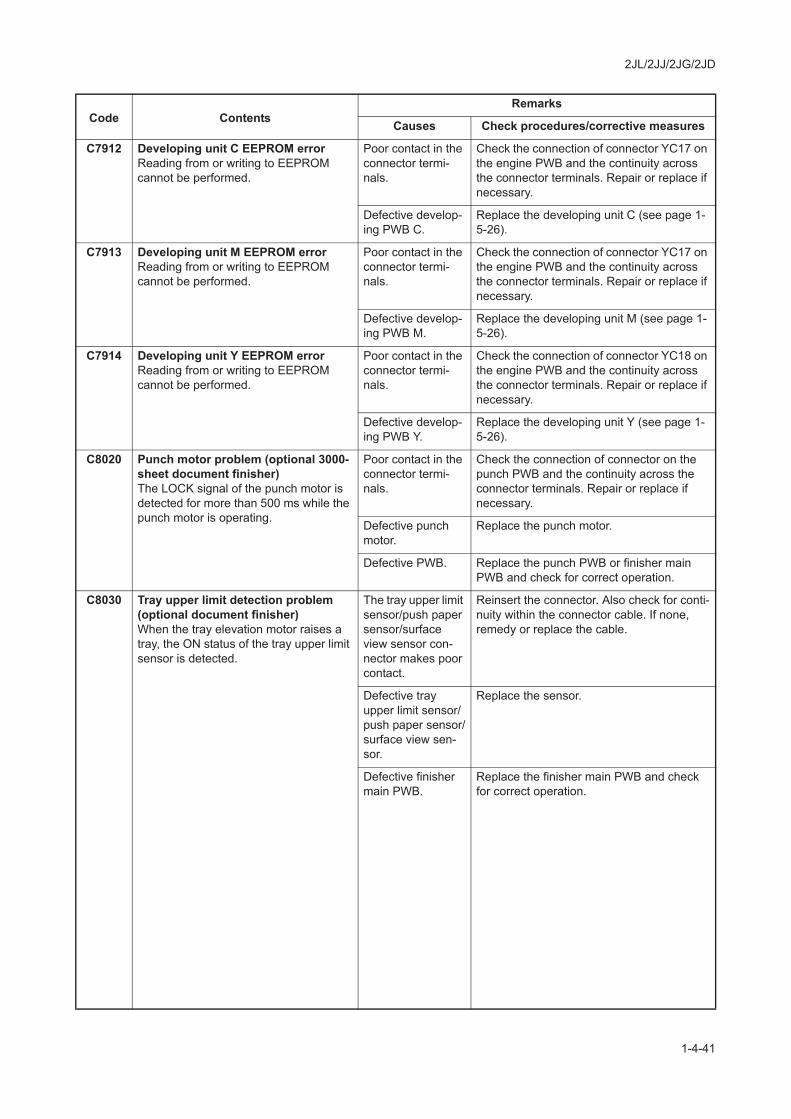
C7912 Developing unit C EEPROM errorReading from or writing to EEPROM cannot be performed.
Poor contact in the connector termi-nals.
Check the connection of connector YC17 on the engine PWB and the continuity across the connector terminals. Repair or replace if necessary.
Defective develop-ing PWB C.
Replace the developing unit C (see page 1-5-26).
C7913 Developing unit M EEPROM errorReading from or writing to EEPROM cannot be performed.
Poor contact in the connector termi-nals.
Check the connection of connector YC17 on the engine PWB and the continuity across the connector terminals. Repair or replace if necessary.
Defective develop-ing PWB M.
Replace the developing unit M (see page 1-5-26).
C7914 Developing unit Y EEPROM errorReading from or writing to EEPROM cannot be performed.
Poor contact in the connector termi-nals.
Check the connection of connector YC18 on the engine PWB and the continuity across the connector terminals. Repair or replace if necessary.
Defective develop-ing PWB Y.
Replace the developing unit Y (see page 1-5-26).
C8020 Punch motor problem (optional 3000-sheet document finisher)The LOCK signal of the punch motor is detected for more than 500 ms while the punch motor is operating.
Poor contact in the connector termi-nals.
Check the connection of connector on the punch PWB and the continuity across the connector terminals. Repair or replace if necessary.
Defective punch motor.
Replace the punch motor.
Defective PWB. Replace the punch PWB or finisher main PWB and check for correct operation.
C8030 Tray upper limit detection problem (optional document finisher)When the tray elevation motor raises a tray, the ON status of the tray upper limit sensor is detected.
The tray upper limit sensor/push paper sensor/surface view sensor con-nector makes poor contact.
Reinsert the connector. Also check for conti-nuity within the connector cable. If none, remedy or replace the cable.
Defective tray upper limit sensor/push paper sensor/surface view sen-sor.
Replace the sensor.
Defective finisher main PWB.
Replace the finisher main PWB and check for correct operation.
Code ContentsRemarks
Causes Check procedures/corrective measures

2JL/2JJ/2JG/2JD
1-4-42
C8050 Paper conveying belt motor 1 prob-lem (optional 3000-sheet document finisher)Paper conveying belt home position sen-sor 1 does not turn off within 1.5 s.Paper conveying belt home position sen-sor 1 does not turn on within 2.5 s.Jam 88 is indicated.
Poor contact in the connector termi-nals.
Check the connection of connector YC2 on the internal tray PWB and the connector on paper conveying belt motor 1, and the conti-nuity across the connector terminals. Repair or replace if necessary.
Defective paper conveying belt home position sen-sor 1.
Replace paper conveying belt home position sensor 1.
Defective paper conveying belt motor 1.
Replace paper conveying belt motor 1.
Defective PWB. Replace the internal tray PWB or finisher main PWB and check for correct operation.
C8060 Paper conveying belt motor 2 prob-lem (optional 3000-sheet document finisher)Paper conveying belt home position sen-sor 2 does not turn off within 1.5 s.Paper conveying belt home position sen-sor 2 does not turn on within 1.5 s.
Poor contact in the connector termi-nals.
Check the connection of connector YC6 on the internal tray PWB and the connector on paper conveying belt motor 2, and the conti-nuity across the connector terminals. Repair or replace if necessary.
Defective paper conveying belt home position sen-sor 2.
Replace paper conveying belt home position sensor 2.
Defective paper conveying belt motor 2.
Replace paper conveying belt motor 2.
Defective PWB. Replace the internal tray PWB or finisher main PWB and check for correct operation.
C8070 Internal tray communication error (optional 3000-sheet document fin-isher)Communication with the internal tray is not possible although the connection is detected.
Poor contact in the connector termi-nals.
Check the connection of connector YC6 on the finisher main PWB and the connector YC1 on the internal tray PWB, and the conti-nuity across the connector terminals. Repair or replace if necessary.
Defective PWB. Replace the internal tray PWB or finisher main PWB and check for correct operation.
Code ContentsRemarks
Causes Check procedures/corrective measures

2JL/2JJ/2JG/2JD
1-4-43
C8140 Main tray problem (optional 3000-sheet document finisher)The main tray is not detected by the main tray upper limit detection sensor or the main tray paper upper surface detec-tion sensor within 20s since the tray has started ascending.The main tray upper limit detection sen-sor or the main tray paper upper surface detection sensor is not detected to be turned off in 20 s after the main tray has descended.The main tray low limit detection sensor is not detected to be turned on in 20 s after the main tray has descended.During main tray ascent, the main tray upper limit detection sensor or the main tray paper upper surface detection sen-sor stays on for more than 2 s.
Poor contact in the connector termi-nals.
Check the connection of connector YC6 on the finisher main PWB and the connector on the main tray motor, and the continuity across the connector terminals. Repair or replace if necessary.
Defective main tray motor.
Replace the main tray motor.
Defective main tray upper limit detec-tion sensor/main tray paper upper surface detection sensor/main tray lower limit detec-tion sensor.
Replace the sensor.
Defective finisher main PWB.
Replace the finisher main PWB and check for correct operation.
Tray elevation motor problem (optional document finisher)The tray low limit sensor, paper retaining sensor or paper surface sensor cannot be detected to be on within 10 s since the tray elevation motor is activated.
The tray elevation motor connector makes poor con-tact.
Reinsert the connector. Also check for conti-nuity within the connector cable. If none, remedy or replace the cable.
The tray elevation motor malfunc-tions.
Replace the tray elevation motor.
The tray lower limit sensor/push paper sensor/surface view sensor con-nector makes poor contact.
Reinsert the connector. Also check for conti-nuity within the connector cable. If none, remedy or replace the cable.
Defective tray lower limit sensor/push paper sensor/surface view sen-sor.
Replace the sensor.
Defective finisher main PWB.
Replace the finisher main PWB and check for correct operation.
Code ContentsRemarks
Causes Check procedures/corrective measures

2JL/2JJ/2JG/2JD
1-4-44
C8170 Side registration motor 1 problem (optional 3000-sheet document fin-isher)When operation returned to a home position is performed at the time of initial operation and a home position is not detected even if 3 s passed.Jam 88 is indicated.
Poor contact in the connector termi-nals.
Check the connection of connector YC2 on the internal tray PWB and the connector on side registration motor 1, and the continuity across the connector terminals. Repair or replace if necessary.
Defective side reg-istration motor 1.
Replace side registration motor 1.
Defective PWB. Replace the internal tray PWB or finisher main PWB and check for correct operation.
Adjustment motor problem (optional document finisher)The registration home position sensor cannot be detected to be on or off within 125 ms since the registration motor is activated after registration has started.The registration home position sensor cannot be detected to be on within 710 ms since the registration motor is acti-vated after registration has ceased.
The adjustment motor connector makes poor con-tact.
Reinsert the connector. Also check for conti-nuity within the connector cable. If none, remedy or replace the cable.
Defective adjust-ment motor.
Replace adjustment motor.
The adjustment home position sen-sor connector makes poor con-tact.
Reinsert the connector. Also check for conti-nuity within the connector cable. If none, remedy or replace the cable.
Defective adjust-ment home posi-tion sensor.
Replace the adjustment home position sen-sor.
Defective finisher main PWB.
Replace the finisher main PWB and check for correct operation.
C8180 Side registration motor 2 problem (optional 3000-sheet document fin-isher)When operation returned to a home position is performed at the time of initial operation and a home position is not detected even if 3 s passed.Jam 88 is indicated.
Poor contact in the connector termi-nals.
Check the connection of connector YC8 on the internal tray PWB and the connector of side registration motor 2, and the continuity across the connector terminals. Repair or replace if necessary.
Defective side reg-istration motor 2.
Replace side registration motor 2.
Defective PWB. Replace the internal tray PWB or finisher main PWB and check for correct operation.
Code ContentsRemarks
Causes Check procedures/corrective measures
2JL/2JJ/2JG/2JD
1-4-45
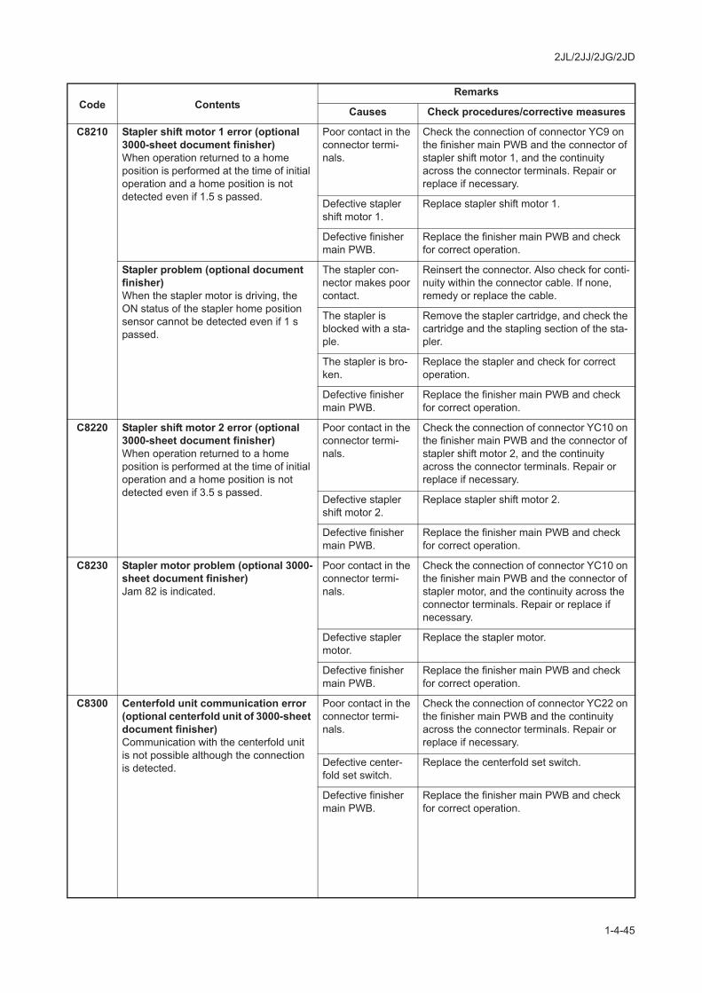
C8210 Stapler shift motor 1 error (optional 3000-sheet document finisher)When operation returned to a home position is performed at the time of initial operation and a home position is not detected even if 1.5 s passed.
Poor contact in the connector termi-nals.
Check the connection of connector YC9 on the finisher main PWB and the connector of stapler shift motor 1, and the continuity across the connector terminals. Repair or replace if necessary.
Defective stapler shift motor 1.
Replace stapler shift motor 1.
Defective finisher main PWB.
Replace the finisher main PWB and check for correct operation.
Stapler problem (optional document finisher)When the stapler motor is driving, the ON status of the stapler home position sensor cannot be detected even if 1 s passed.
The stapler con-nector makes poor contact.
Reinsert the connector. Also check for conti-nuity within the connector cable. If none, remedy or replace the cable.
The stapler is blocked with a sta-ple.
Remove the stapler cartridge, and check the cartridge and the stapling section of the sta-pler.
The stapler is bro-ken.
Replace the stapler and check for correct operation.
Defective finisher main PWB.
Replace the finisher main PWB and check for correct operation.
C8220 Stapler shift motor 2 error (optional 3000-sheet document finisher)When operation returned to a home position is performed at the time of initial operation and a home position is not detected even if 3.5 s passed.
Poor contact in the connector termi-nals.
Check the connection of connector YC10 on the finisher main PWB and the connector of stapler shift motor 2, and the continuity across the connector terminals. Repair or replace if necessary.
Defective stapler shift motor 2.
Replace stapler shift motor 2.
Defective finisher main PWB.
Replace the finisher main PWB and check for correct operation.
C8230 Stapler motor problem (optional 3000-sheet document finisher)Jam 82 is indicated.
Poor contact in the connector termi-nals.
Check the connection of connector YC10 on the finisher main PWB and the connector of stapler motor, and the continuity across the connector terminals. Repair or replace if necessary.
Defective stapler motor.
Replace the stapler motor.
Defective finisher main PWB.
Replace the finisher main PWB and check for correct operation.
C8300 Centerfold unit communication error (optional centerfold unit of 3000-sheet document finisher)Communication with the centerfold unit is not possible although the connection is detected.
Poor contact in the connector termi-nals.
Check the connection of connector YC22 on the finisher main PWB and the continuity across the connector terminals. Repair or replace if necessary.
Defective center-fold set switch.
Replace the centerfold set switch.
Defective finisher main PWB.
Replace the finisher main PWB and check for correct operation.
Code ContentsRemarks
Causes Check procedures/corrective measures

2JL/2JJ/2JG/2JD
1-4-46
C8310 Centerfold side registration motor 1 problem (optional centerfold unit of 3000-sheet document finisher)The home position is not detected when initial operation even if 1 s passed.
Poor contact in the connector termi-nals.
Check the connection of connector YC6 on the centerfold main PWB and the connector of centerfold side registration motor 1, and the continuity across the connector termi-nals. Repair or replace if necessary.
Defective center-fold side registra-tion motor 1.
Replace centerfold side registration motor 1.
Defective PWB. Replace the centerfold main PWB or finisher main PWB and check for correct operation.
C8320 Centerfold paper conveying belt motor problem (optional centerfold unit of 3000-sheet document finisher)The home position is not detected when initial operation even if 2.5 s passed.
Poor contact in the connector termi-nals.
Check the connection of connector YC6, YC7 on the centerfold main PWB and the connector of centerfold paper conveying belt motor 1/2, and the continuity across the con-nector terminals. Repair or replace if neces-sary.
Defective center-fold paper convey-ing belt motor 1/2.
Replace centerfold paper conveying belt motor 1/2.
Defective PWB. Replace the centerfold main PWB or finisher main PWB and check for correct operation.
C8330 Blade motor problem (optional cen-terfold unit of 3000-sheet document finisher)The home position is not detected when initial operation even if 1.5 s passed.
Poor contact in the connector termi-nals.
Check the connection of connector YC8 on the centerfold main PWB and the connector of the blade motor, and the continuity across the connector terminals. Repair or replace if necessary.
Defective blade motor.
Replace the blade motor.
Defective PWB. Replace the centerfold main PWB or finisher main PWB and check for correct operation.
C8340 Centerfold staple motor problem (optional centerfold unit of 3000-sheet document finisher)Jam89 is indicated.
Poor contact in the connector termi-nals.
Check the connection of connector YC9 on the centerfold main PWB and the connector of the centerfold staple motor, and the conti-nuity across the connector terminals. Repair or replace if necessary.
Defective center-fold staple motor.
Replace the centerfold staple motor.
Defective PWB. Replace the centerfold main PWB or finisher main PWB and check for correct operation.
C8350 Centerfold side registration motor 2 problem (optional centerfold unit of 3000-sheet document finisher)The home position is not detected when initial operation even if 1 s passed.
Poor contact in the connector termi-nals.
Check the connection of connector YC7 on the centerfold main PWB and the connector of centerfold side registration motor 2, and the continuity across the connector termi-nals. Repair or replace if necessary.
Defective center-fold side registra-tion motor 2.
Replace centerfold side registration motor 1.
Defective PWB. Replace the centerfold main PWB or finisher main PWB and check for correct operation.
Code ContentsRemarks
Causes Check procedures/corrective measures

2JL/2JJ/2JG/2JD
1-4-47
C8360 Centerfold main motor problem (optional centerfold unit of 3000-sheet document finisher)The motor lock signal is detected above 1 s during driving the centerfold main motor.
Poor contact in the connector termi-nals.
Check the connection of connector YC12 on the centerfold main PWB and the connector of the centerfold main motor, and the conti-nuity across the connector terminals. Repair or replace if necessary.
Defective center-fold main motor.
Replace the centerfold main motor.
Defective PWB. Replace the centerfold main PWB or finisher main PWB and check for correct operation.
C8440 Sensor adjusting problem (optional document finisher)The sensor cannot be adjusted within the specified range.
The paper entry sensor connector makes poor con-tact.
Reinsert the connector. Also check for conti-nuity within the connector cable. If none, remedy or replace the cable.
Defective paper entry sensor.
Replace the paper entry sensor and check for correct operation.
The optical path of the paper entry sensor is blocked by foreign matter.
Remove the foreign matter.
Defective finisher main PWB.
Replace the finisher main PWB and check for correct operation.
C8460 EEPROM problem (optional document finisher)Read and write data does not match 3 times in succession.
Defective EEPROM or fin-isher main PWB.
Replace the finisher main PWB and check for correct operation.
C8500 Mailbox communication error (optional mailbox of 3000-sheet docu-ment finisher)Communication with the mailbox is not possible although the connection is detected.
Poor contact in the connector termi-nals.
Check the connection of the connector of the mailbox and the connector YC7 on the finisher main PWB, and the continuity across the connector terminals. Repair or replace if necessary.
Defective PWB. Replace the mailbox main PWB or finisher main PWB and check for correct operation.
C8510 Mailbox drive motor problem (optional mailbox of 3000-sheet docu-ment finisher)The motor lock signal is detected above 500 ms during driving the mailbox drive motor.
Poor contact in the connector termi-nals.
Check the connection of connector YC2 on the mailbox main PWB and the connector of the mailbox drive motor, and the continuity across the connector terminals. Repair or replace if necessary.
Defective mailbox drive motor.
Replace the mailbox drive motor.
Defective PWB. Replace the mailbox main PWB or finisher main PWB and check for correct operation.
C8900 Backup memory data problem (optional 3000-sheet document fin-isher)Read and write data does not match 3 times in succession.
Poor contact in the connector termi-nals.
Check the connection of connector on the finisher main PWB and the connector of the machine, and the continuity across the con-nector terminals. Repair or replace if neces-sary.
Defective finisher main PWB.
Replace the finisher main PWB and check for correct operation.
Code ContentsRemarks
Causes Check procedures/corrective measures

2JL/2JJ/2JG/2JD
1-4-48
C8910 Backup memory data problem (optional 3000-sheet document fin-isher)Read and write data does not match 3 times in succession.
Poor contact in the connector termi-nals.
Check the connection of connector on the punch PWB and the connector YC4 on the finisher main PWB, and the continuity across the connector terminals. Repair or replace if necessary.
Defective punch PWB.
Replace the punch PWB and check for cor-rect operation.
C8920 Backup memory data problem (optional mailbox of 3000-sheet docu-ment finisher)Read and write data does not match 3 times in succession.
Poor contact in the connector termi-nals.
Check the connection of connector on the mailbox main PWB and the connector YC7 on the finisher main PWB, and the continuity across the connector terminals. Repair or replace if necessary.
Defective mailbox main PWB.
Replace the mailbox main PWB and check for correct operation.
C8930 Backup memory data problem (optional centerfold unit of 3000-sheet document finisher)Read and write data does not match 3 times in succession.
Poor contact in the connector termi-nals.
Check the connection of connector on the centerfold main PWB and the connector YC5 on the finisher main PWB, and the con-tinuity across the connector terminals. Repair or replace if necessary.
Defective center-fold main PWB.
Replace the centerfold main PWB and check for correct operation.
C9060 EEPROM problem (optional DP)Read and write data does not match.
Poor contact in the connector termi-nals.
Check the connection of connector YC7 on the scanner PWB and the continuity across the connector terminals. Repair or replace if necessary.
Defective DP drive PWB.
Replace DP drive PWB and check for cor-rect operation.
C9500 Contact the Service Administrative Division.
C9510 Contact the Service Administrative Division.
C9520 Contact the Service Administrative Division.
C9530 Contact the Service Administrative Division.
C9540 Contact the Service Administrative Division.
C9550 Contact the Service Administrative Division.
Code ContentsRemarks
Causes Check procedures/corrective measures