errors in dic.pdf
DESCRIPTION
errorsTRANSCRIPT
Optics and Lasers in Engineering 49 (2011) 57–65
Contents lists available at ScienceDirect
Optics and Lasers in Engineering
0143-81
doi:10.1
� Corr
E-m
journal homepage: www.elsevier.com/locate/optlaseng
Error estimation in measuring strain fields with DIC on planar sheet metalspecimens with a non-perpendicular camera alignment
P. Lava a,�, S. Coppieters a, Y. Wang b, P. Van Houtte b, D. Debruyne a,b
a Catholic University College Ghent, Association K.U. Leuven, Department of Mechanical Engineering, Gebroeders Desmetstraat 1, B-9000 Gent, Belgiumb Department MTM, Katholieke Universiteit Leuven, Kasteelpark Arenberg 44, B-3001 Leuven (Heverlee), Belgium
a r t i c l e i n f o
Article history:
Received 8 July 2010
Received in revised form
30 August 2010
Accepted 30 August 2010Available online 16 September 2010
Keywords:
Digital image correlation
Stereo vision
Strain calculations
Systematic errors
Finite element simulations
66/$ - see front matter & 2010 Elsevier Ltd. A
016/j.optlaseng.2010.08.017
esponding author. Tel.: +32 9 2658722; fax:
ail address: [email protected] (P. Lava).
a b s t r a c t
The determination of strain fields based on displacement components obtained via 2D-DIC is subject to
several errors that originate from various sources. In this contribution, we study the impact of a non-
perpendicular camera alignment to a planar sheet metal specimen’s surface. The errors are estimated in
a numerical experiment. To this purpose, deformed images – that were obtained by imposing finite
element (FE) displacement fields on an undeformed image – are numerically rotated for various Euler
angles. It is shown that a 3D-DIC stereo configuration induces a substantial compensation for the
introduced image-plane displacement gradients. However, higher strain accuracy and precision are
obtained – up to the level of a perfect perpendicular alignment – in a proposed ‘‘rectified’’ 2D-DIC setup.
This compensating technique gains benefit from both 2D-DIC (single camera view, basic amount of
correlation runs, no cross-camera matching nor triangulation) and 3D-DIC (oblique angle compensa-
tion). Our conclusions are validated in a real experiment on SS304.
& 2010 Elsevier Ltd. All rights reserved.
1. Introduction
Digital image correlation (DIC), being a member of the class ofoptical full-field measurement methods, has undergone contin-uous modification and improvement since the early eighties. As aresult, DIC experiments are currently extensively applied to studye.g. the deformation characteristics of a wide range of materials intensile experiments on planar specimens [1–8]. One of the majordrawbacks of the technique, however, is the absence of a clearerror estimation on the obtained experimental results.
Recently, elaborate studies have been dedicated to thevalidation of single camera DIC (designated 2D-DIC) displacementand strain fields [9–21]. In theory, however, 2D-DIC is restrictedto planar specimens subject to in-plane deformations. In addition,the single recording camera is assumed to be perpendicularlyaligned with the specimen’s surface. If not, relative out-of-planemotion of the specimen with respect to the imaging system willintroduce image-plane displacement gradients, resulting incorrupted displacement and strain field data [22]. One possiblesolution to accommodate for this kind of experimental noise is astereovision 3D-DIC system setup, employing two or morecameras to record the specimen from various points of view.The stereo system, however, involves multiple correlation runs,including cross-camera subset matching. In addition, a stereosystem urges the input of calibration data. Accordingly, at the
ll rights reserved.
+32 9 2658648.
eventual benefit of avoiding errors due to deviations fromplanarity, one introduces (other) extra error sources in theobtained displacement and strain fields.
In the past, the effect of out-of-plane motion on 2D and 3D DICmeasurements was the subject of investigation in Refs. [14,22]. Itwas shown that a single 2D imaging system is sensitive to out-of-plane translation (DZ=Z, where Z is the distance from the object tothe pin hole and DZ the out-of-plane translation displacement)and out-of-plane rotation (function of both rotation angle andimage distance Z). Accordingly, to minimize the effect of out-of-plane motion on 2D-DIC measurements one can increase theimage distance or alternatively use a telecentric lens. In addition,it was shown that a stereovision system measures all displace-ment components with relatively high accuracy.
The above-mentioned papers, however, focussed on rigid bodydeformations of the specimen. In Refs. [16,23], errors in 2D-DICdisplacement and strain fields were investigated in regions withlarge heterogeneous deformations. It was shown that consciouschoices in the interpolation order, shape function, subset size,strain-window size and strain-window interpolation order shouldbe made according to the spatial variation of the strain fields. Inview of the multiple correlation runs and cross-camera subsetmatching in a 3D-DIC system, the accumulating effect of theseadditional error sources may extinguish the benefits of the out-of-plane displacement compensation.
In this paper, we estimate the errors involved in a 3D-DIC stereosetup using a similar procedure as outlined in Refs. [16,23], focussingon a realistic uni-axial tensile test on a perforated tensile sheet metalspecimen subject to large in-plane plastic deformation. A reference

Fig. 1. Reference speckle pattern for the uni-axial tensile test with a subset of
19�19 pixels (left), mesh pattern with the applied force (middle) and speckle
pattern with finite element deformation (right panel) corresponding to epleq ¼ 0:21.
Fig. 2. Euler reference rotation frame (left), rotated reference speckle pattern
corresponding to fðyÞ (middle) and yðxÞ (right) angle of 301.
P. Lava et al. / Optics and Lasers in Engineering 49 (2011) 57–6558
image is numerically deformed by imposing finite element (FE)displacement fields corresponding to various load steps. These areobtained by the commercial software package Abaqus [24]. Next, thereference image and numerically deformed images corresponding tolarge plastic strains are numerically rotated for various Euler angles.The unrotated images are considered as taken by camera 1, therotated as captured by camera 2. An identical rotation procedure isadopted to a calibration pattern, allowing the determination of thespecific camera parameters. Accordingly, we can validate our strainpredictions obtained in a simulated perpendicular (camera 1), non-perpendicular (camera 2) and stereo setup on a planar specimen athigh plastic deformation by comparing them to the well-known FEstrain fields at the Gauss points. All DIC results are computed withour recently developed inhouse DIC platform ‘‘MatchID’’ [25].
It is important to remark that our validation procedure isnumerical by nature. As such, we are not sensitive to differencesin lighting conditions and, moreover, we can avoid out-of-planerotations/translations in the perpendicular setup due to (a)Poisson’s effect (b) small amounts of specimen bending (c) localnecking during the loading process and (d) deviations from idealgrip constraints. We are well aware that in a realistic experimentthese effects are hard to avoid, but can be minimized whenappropriate experimental conditions are fulfilled.
Finally, we propose a compensating technique which gains benefitfrom both 2D-DIC (single camera view, basic amount of correlationruns, no cross-camera subset matching and triangulation) and 3D-DIC(out-of-plane displacement compensation) implementations. In thisso-called ‘‘rectified 2D-DIC’’ setup we first rectify the non-perpendi-cular images with the obtained camera parameters, simulating aperpendicular alignment in a single camera setup. Next, this newprocedure is verified by a real experiment on SS304.
The outline of this article is as follows. In Section 2 we presentthe formalism for the numerical deformation and out-of-planerotation of the reference images. In Section 3 the 3D-DIC system isdescribed, whereas in Section 4 attention is paid to the procedureof rectification. Our results, both numerical and experimental areincluded in Section 5. We conclude in Section 6.
2. Generation of synthetic images
In order to construct our numerical images, a similarprocedure is adopted as in Refs. [16,23]. First, the deformedimages are obtained by imposing finite element (FE) displacementfields on an undeformed image yielding plastic deformation of thespecimen. In particular, Abaqus [24] was used to simulate an uni-axial tensile test on a perforated tensile specimen. The specimenhas a thickness of 0.8 mm in the simulation and assumes a vonMises yield criterion in combination with an isotropic hardeningbehaviour that was derived from tests on SS 304 sheet metal:s ¼ 1533ð0:033þeÞ0:48. The mesh that was generated to performthe calculations is shown in the centre panel of Fig. 1, with thearrow denoting the direction of the applied force. The FEcalculation yields well-known displacement fields at the nodalpoints and strain values at the Gauss points of the finite elements.The average generated elements have a size of approximately3�3 pixels. Next, the nodal displacements are used to numeri-cally deform a random speckle pattern displayed in the left panelof Fig. 1, representing an undeformed state. The displacementfields at integer pixel locations are determined through bicubicinterpolation within the corresponding finite element. The rightpanel of this figure shows the resulting numerically deformedimage corresponding to a maximum equivalent plastic strainof 0.21.
By construction, the reference image and the numericallydeformed images correspond to a camera point of view with
sensor plane parallel to the object plane. In order to investigatethe impact of a non-perpendicular alignment of the camera to theobject plane, we need to numerically rotate the reference anddeformed images. A 3D rotation around the origin yields arotation matrix
R¼
cosccosf coscsinfsiny�sinccosy coscsinfcosyþsincsinysinccosf sincsinfsinyþcosccosy sincsinfcosy�coscsiny�sinf cosfsiny cosfcosy
264
375,
ð1Þ
where y,f,c represent the Euler angles around the X-, Y- andZ-axis, respectively (see Fig. 2). The rotated image coordinates canthen be obtained as
xrotim
yrotim
" #¼
R11ximþR12yim
R31ximþR32yim
R21ximþR22yim
R31ximþR32yim
26664
37775¼
xim
yim
" #þ
q
r
� �: ð2Þ
A similar procedure can now be adopted as for the numericaldeformation case. Indeed, as depicted in Eq. (2) the rotated imagecoordinates (xim
rot,yimrot) yield well-known displacement fields q and r
with respect to the reference coordinates. Again, the resultinggreyscale values at integer pixel locations are determined throughbicubic interpolation. Since the spatial variation of strain in oneelement is linear, one can expect that the additional errors due tothis interpolation procedure are minor. In Fig. 2 the rotatedreference pattern is shown corresponding to a rotation around theX- and Y-axis.
P. Lava et al. / Optics and Lasers in Engineering 49 (2011) 57–65 59
3. 3D digital image correlation
3.1. Formalism
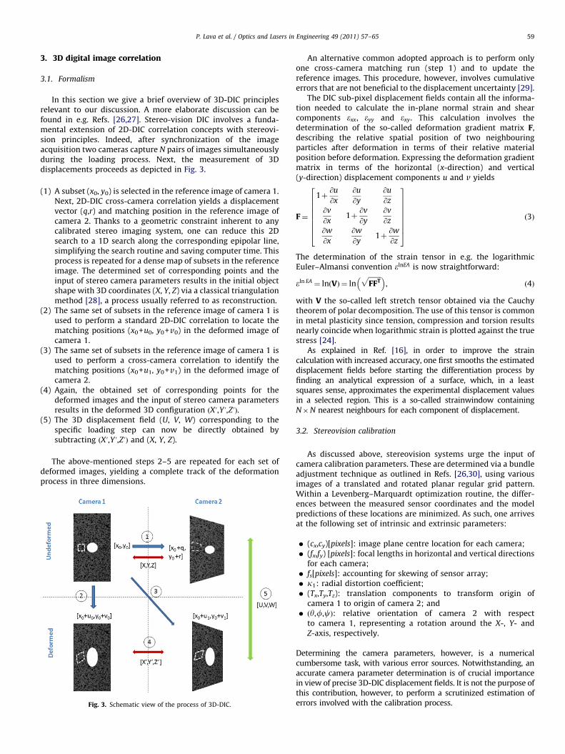
In this section we give a brief overview of 3D-DIC principlesrelevant to our discussion. A more elaborate discussion can befound in e.g. Refs. [26,27]. Stereo-vision DIC involves a funda-mental extension of 2D-DIC correlation concepts with stereovi-sion principles. Indeed, after synchronization of the imageacquisition two cameras capture N pairs of images simultaneouslyduring the loading process. Next, the measurement of 3Ddisplacements proceeds as depicted in Fig. 3.
(1)
A subset (x0, y0) is selected in the reference image of camera 1.Next, 2D-DIC cross-camera correlation yields a displacementvector (q,r) and matching position in the reference image ofcamera 2. Thanks to a geometric constraint inherent to anycalibrated stereo imaging system, one can reduce this 2Dsearch to a 1D search along the corresponding epipolar line,simplifying the search routine and saving computer time. Thisprocess is repeated for a dense map of subsets in the referenceimage. The determined set of corresponding points and theinput of stereo camera parameters results in the initial objectshape with 3D coordinates (X, Y, Z) via a classical triangulationmethod [28], a process usually referred to as reconstruction.(2)
The same set of subsets in the reference image of camera 1 isused to perform a standard 2D-DIC correlation to locate thematching positions (x0+u0, y0+v0) in the deformed image ofcamera 1.(3)
The same set of subsets in the reference image of camera 1 isused to perform a cross-camera correlation to identify thematching positions (x0+u1, y0+v1) in the deformed image ofcamera 2.(4)
Again, the obtained set of corresponding points for thedeformed images and the input of stereo camera parametersresults in the deformed 3D configuration ðXu,Y u,ZuÞ.(5)
The 3D displacement field (U, V, W) corresponding to thespecific loading step can now be directly obtained bysubtracting ðXu,Y u,ZuÞ and (X, Y, Z).The above-mentioned steps 2–5 are repeated for each set ofdeformed images, yielding a complete track of the deformationprocess in three dimensions.
Fig. 3. Schematic view of the process of 3D-DIC.
An alternative common adopted approach is to perform onlyone cross-camera matching run (step 1) and to update thereference images. This procedure, however, involves cumulativeerrors that are not beneficial to the displacement uncertainty [29].
The DIC sub-pixel displacement fields contain all the informa-tion needed to calculate the in-plane normal strain and shearcomponents exx, eyy and exy. This calculation involves thedetermination of the so-called deformation gradient matrix F,describing the relative spatial position of two neighbouringparticles after deformation in terms of their relative materialposition before deformation. Expressing the deformation gradientmatrix in terms of the horizontal (x-direction) and vertical(y-direction) displacement components u and v yields
F¼
1þ@u
@x
@u
@y
@u
@z@v
@x1þ
@v
@y
@v
@z@w
@x
@w
@y1þ
@w
@z
266666664
377777775
ð3Þ
The determination of the strain tensor in e.g. the logarithmicEuler–Almansi convention elnEA is now straightforward:
eln EA ¼ lnðVÞ ¼ lnffiffiffiffiffiffiffiffiFFT
p� �, ð4Þ
with V the so-called left stretch tensor obtained via the Cauchytheorem of polar decomposition. The use of this tensor is commonin metal plasticity since tension, compression and torsion resultsnearly coincide when logarithmic strain is plotted against the truestress [24].
As explained in Ref. [16], in order to improve the straincalculation with increased accuracy, one first smooths the estimateddisplacement fields before starting the differentiation process byfinding an analytical expression of a surface, which, in a leastsquares sense, approximates the experimental displacement valuesin a selected region. This is a so-called strainwindow containingN�N nearest neighbours for each component of displacement.
3.2. Stereovision calibration
As discussed above, stereovision systems urge the input ofcamera calibration parameters. These are determined via a bundleadjustment technique as outlined in Refs. [26,30], using variousimages of a translated and rotated planar regular grid pattern.Within a Levenberg–Marquardt optimization routine, the differ-ences between the measured sensor coordinates and the modelpredictions of these locations are minimized. As such, one arrivesat the following set of intrinsic and extrinsic parameters:
�
(cx,cy)[pixels]: image plane centre location for each camera; � (fx,fy) [pixels]: focal lengths in horizontal and vertical directionsfor each camera;
� fs[pixels]: accounting for skewing of sensor array; � k1: radial distortion coefficient; � (Tx,Ty,Tz): translation components to transform origin ofcamera 1 to origin of camera 2; and
� ðy,f,cÞ: relative orientation of camera 2 with respectto camera 1, representing a rotation around the X-, Y- andZ-axis, respectively.
Determining the camera parameters, however, is a numericalcumbersome task, with various error sources. Notwithstanding, anaccurate camera parameter determination is of crucial importancein view of precise 3D-DIC displacement fields. It is not the purpose ofthis contribution, however, to perform a scrutinized estimation oferrors involved with the calibration process.

0
0.02
0.04
0.06
0.08
0.1Δq
av
11
2131
41
φ (deg)
σ
0
0.025
0.05
0.075
0.1
0 5 10 15 20 25 30 35 40
Fig. 5. Impact of the subset size on the mean systematic errors (upper panels) and
standard deviation (lower panels) for cross-camera horizontal displacements as a
function of out-of-plane rotation around the Y-axis. The solid, dashed, dot-dashed,
and dotted lines represent a subset size of 11 �11, 21�21, 31�31 and 41�41,
respectively.
P. Lava et al. / Optics and Lasers in Engineering 49 (2011) 57–6560
3.3. Error estimation in cross-camera matching
In Section 5 the overall errors for the 3D-DIC system will bestudied. Before embarking on this, we should first clearlyunderstand the roots of these errors. Indeed, as can be inferredfrom Fig. 3, a 3D-DIC stereo system involves various correlationruns and reconstruction, each of them with their specific errorscontributing to the overall accuracy and precision of themeasurement. Errors due to reconstruction in image stereo-correlation were the subject of investigation in Ref. [31]. Errorestimation (process 2) in regular single camera 2D-DIC wasalready the subject of our investigation in Refs. [16,23]. It wasshown that the impact of the subset size on the strain precisionpersists, even when a smoothing procedure as outlined above isimplemented. Cross-camera 2D-DIC matching (process 1), how-ever, needs some further investigation. Due to the numericalrotation process of the images, we are provided with well-knowndisplacement values (q,r) in Eq. (2), allowing us to estimate theerrors of the displacement results obtained by 2D-DIC calcula-tions. In this section we are only interested in errors due to thecross-camera matching. As such, a full 2D search across the entireimage is performed instead of a 1D search along the correspond-ing epipolar line, since this latter would introduce errors due tothe calibration procedure. In the overall 3D DIC mechanism,however, this epipolar constraint is incorporated.
A similar procedure is followed as outlined in Ref. [16] inwhich we calculate the mean Dqav and the standard deviation s ofthe measured differences Dq¼ qimp�qDIC . The following standardsettings are adopted: rASSD, affine transformation, bicubic inter-polation and a subset size of 21�21. The errors on the verticaldisplacement components r and for rotations around the X-axisare not shown since they are of the same order, yielding similarconclusions concerning the impact of the parameter underinvestigation.
First, in Fig. 4, we study the impact of the adopted DICinterpolation order on the cross-camera matching. As stated inRef. [11], an accurate choice of this quantity is of the utmostimportance in the DIC algorithm since it introduces a largereduction in the bias of displacement fields when going frombilinear to bicubic interpolation order. As can be inferred, thisconclusion is confirmed for stereo angles ranging from 5 up to 401,with the bicubic and bicubic spline routines yielding the optimumresults.
0
0.02
0.04
0.06
0.08
0.1
Δqav
BC
BCSPLINEBL
φ (deg)
σ
0
0.025
0.05
0.075
0.1
0 5 10 15 20 25 30 35 40
Fig. 4. Impact of the interpolation order on the mean systematic errors (upper
panels) and standard deviation (lower panels) for cross-camera horizontal
displacements as a function of out-of-plane rotation around the Y-axis. The solid,
dashed and dot-dashed lines adopt a bicubic (BC), bicubic spline (BCSPLINE) and
bilinear (BL) interpolation routine, respectively.
Next, in Fig. 5 the mean error and corresponding standarddeviations are displayed for different dimensions of the subset asa function of the rotation angle with respect to the Y-axis. As canbe inferred, the accuracy and precision are relatively high whensmall subset sizes in combination with stereo angles below 301are considered. Larger subset sizes and stereo angles involvequestionable matching results. This is in agreement with theresults of Ref. [26]. The choice for a small subset size, however, is aventure into dangerous territory since its lower limit is estab-lished by the granularity of the speckle pattern. As such, one canwonder if it is not possible to keep the subset size fixed to areasonable large value combined with an alternate shapefunction. In Ref. [26], one considers a homographic shapefunction, which reads as
mðx,y,sÞ
nðx,y,sÞ
" #¼
s0xþs1yþs2
s6xþs7yþ1s3xþs4yþs5
s6xþs7yþ1
2664
3775: ð5Þ
This a more natural approach to describe cross-camera displace-ments in view of the perspective projection of planar objects. InEq. (5), (x,y) and ðm,nÞ represent the pixel positions in the image
0
0.025
0.05
0.075
0.1
Δqav
AffineIrregularQuadratic
φ (deg)
σ
0
0.025
0.05
0.075
0.1
0 5 10 15 20 25 30 35 40
Fig. 6. Impact of the subset shape function on the mean systematic errors (upper
panels) and standard deviation (lower panels) for cross-camera horizontal
displacements as a function of out-of-plane rotation around the Y-axis. The solid,
dashed and dot-dashed lines represent the results of affine, irregular and quadratic
transformations, respectively.

-0.0010
0.001
0.002
0.003
0.004
0
0.005
0.01
0.015
-0.001
0
0.001
0.002
0.003
0
0.005
0.01
0.015
0.02
0
0.005
0.01
0.015
Δεxx
Δεyy
2D Perp
2D NonPerp
3D Stereo
2D Rect
Δεxy
φ (deg)
|Mean| σ
0
0.005
0.01
100 20 30 40100 20 30 40
Fig. 7. Impact of an oblique angle observation on the mean error and corresponding standard deviations for various Euler pitch angles at a maximum equivalent plastic
strain of epleq ¼ 0:21. The solid, dashed, dot-dashed and dotted lines correspond to a 2D perpendicular setup, a 2D non-perpendicular setup, a 3D stereo setup and a 2D
rectified setup, respectively.
0
0.0025
0.005
0.0075
0.01
0
0.002
0.004
0.006
0.008
0.01
0
0.0025
0.005
0.0075
0
0.005
0.01
0.015
0
0.0025
0.005
0.0075
3D STEREO
Δεxx
Δεyy
Δεxy
X (mm)
|Mean| σ
0
0.002
0.004
0.006
0.008
0
0.0025
0.005
0.0075
0.01
0
0.002
0.004
0.006
0.008
0.01
0
0.0025
0.005
0.0075
0
0.005
0.01
0.015
0
0.0025
0.005
0.0075
2D RECT
Φ = 5Φ = 15Φ = 30
Φ = 40
X (mm)
|Mean| σ
0
0.002
0.004
0.006
0.008
-20
Δεxx
Δεyy
Δεxy
-10 0 10 20-20 -10 0 10
-20 -10 0 10 20-20 -10 0 10
Fig. 8. Mean error and standard deviations for a stereo 3D-DIC (a) and 2D-DIC rectified (b) setup at a maximum equivalent plastic strain of epleq ¼ 0:21 as a function of the
distance to the rotation axis. The solid, dashed, dot-dashed and dotted lines correspond to various Euler pitch angles.
P. Lava et al. / Optics and Lasers in Engineering 49 (2011) 57–65 61

P. Lava et al. / Optics and Lasers in Engineering 49 (2011) 57–6562
frame of camera 1 and 2, respectively, whereas s is the parametervector to be identified. A homographic shape function was testedin our approach, but in accordance with Ref. [26], convergenceproblems appeared during the matching process. A valid alter-native is to use rectified images for which the epipolar lines arehorizontal and aligned. Unfortunately, this involves additionalinterpolation, at the expect of additional positional errors. In thiscontribution, we chose to alter the order of the subset shapefunction. In Fig. 6, the impact of an irregular and quadratic shapefunction on the mean errors and standard deviations is shown.These transformation orders were defined in Ref. [16]. As can beinferred, the introduction of quadratic terms substantiallyimproves the cross-camera matching process. This is not surpris-ing since a first-order Taylor expansion of the above-mentioned‘‘more natural’’ homography produces quadratic terms. Moreover,the quadratic shape function does not suffer from convergenceproblems.
To conclude, in this section it was shown that 3D-DIC is muchmore complex compared to standard 2D-DIC. Accordingly, onecan already expect that the overall errors for the 3D-DIC systemwill be larger. Before we embark on this, however, we firstconcentrate on a technique that might be a viable alternative tostandard 2D-DIC when the perpendicular condition is not fulfilled.
0
0.0025
0.005
0.0075
0.01
0.008
Δεxx
Φ = 5°
4. Image rectification
It is clear that a 3D-DIC stereosystem as depicted in Section 3.1suffers from multiple error sources due to the accumulation ofvarious 2D-DIC correlation runs (cross-camera and deformationtracking) and the camera calibration procedure. In Section 5 theoverall errors for the 3D-DIC system will be studied. First,however, attention is paid to a technique that gains benefit fromboth 2D-DIC (single camera view, basic amount of correlationruns and no cross-camera subset matching) and 3D-DIC (out-of-plane displacement compensation) implementations. This imagerectification procedure transforms the ‘‘non-perpendicular’’images to a camera point of view perpendicular aligned to thespecimen plane and includes the following steps:
0.004
0.006
σ
(1)
0
0.002
-0.08
0.005
0.0075
0.01
Δεxx
Φ = 30°
2D Perp
2D Rect3D
-0.07 -0.06 -0.05 -0.04 -0.03 -0.02 -0.01 0εxx
As for the 3D-DIC stereo system a clear prerequisite for therectification process is a precise determination of the cameraparameters. As described in Section 3.2, we use a regular gridpattern translated and rotated into various positions. For the firstcalibration image, we put the regular planar grid pattern parallelto the specimen’s surface and at the same position of thespecimen. As such, we can consider the world reference frame asthe frame parallel to the object plane frame. Accordingly, wearrive at six extrinsic parameters (R, T) describing the relativeposition of the camera frame to the (parallel) world referenceframe and the intrinsic parameters fx,fy,fs,cx,cy,k1.
0.0025
(2)0
First, the real distorted images are transformed into idealdistortion-free images.
(3)
σ
0
0.002
0.004
0.006
0.008
-0.08 -0.07 -0.06 -0.05 -0.04 -0.03 -0.02 -0.01 0εxx
Next, the four corners of the specimen’s undistorted imagesare converted from sensor (xs
u, ysu) to world coordinates (XW,
YW, ZW) on the basis of the following relationships (ZW¼0):
xus
yus
" #¼
cxþ fxR11XWþR12YWþTx
R31XWþR32YWþTzþ fs
R21XWþR22YWþTy
R31XWþR32YWþTz
cyþ fyR21XWþR22YWþTy
R31XWþR32YWþTz
26664
37775:ð6Þ
Fig. 9. Mean error and standard deviation for the transverse strain component at
an Euler pitch angle of f¼ 53 (a) and f¼ 303 (b). Results are binned over
(4)equidistant strain intervals. The circles, triangles and squares correspond to a
perpendicular 2D-DIC, a 3D-DIC and a rectified 2D-DIC setup, respectively.
Finally, for all other points the rectification is implementedbackwards, i.e. starting from the new image plane applyingthe inverse transformations of the four corner points. As such
the pixel values in the new image plane can be computed as abicubic interpolation of the integer pixel values in the oldimage plane.
We remark that the rectified image is in general not containedin the same region of the image plane as the original image.Accordingly, one has to adjust the focal lengths of the camera forthe rectification process.
5. Results
5.1. Numerical
Now that we are provided with various DIC frameworks tomeasure displacement and strain fields on planar specimensobserved from an oblique angle, we can embark on the validationprocedure via the numerical experiment as described in Section 2.Since camera 1 and 2 correspond to the unrotated and rotatedimages, respectively, the following numerical achievements areobtained: 2D-DIC perpendicular setup via camera 1, a 2D-DICoblique angle setup via camera 2, a 3D-DIC stereo setup bycombining camera 1 and 2, and a 2D-DIC rectified setup byrectifying the images of camera 2. As stated above, the stereosystem and the rectification procedure require the input ofcamera parameters, both intrinsic and extrinsic. To this purpose,we perform an identical numerical rotation procedure asdescribed in Section 2 on a calibration image of a regular grid

P. Lava et al. / Optics and Lasers in Engineering 49 (2011) 57–65 63
pattern. Next, the fictive camera parameters are estimated in abundle-adjustment calibration procedure, with the Euler anglesfixed to the imposed values. As such, the object distance for allforthcoming numerical results corresponds to Z � 612 mm. Allresults presented below adopt the following standard settings:rASSD, affine transformation, bicubic interpolation, a subset size of21�21, a step size of 2 and a strain window of 10�10 withbilinear interpolation.
Fig. 7 displays the impact of an oblique angle observation onthe mean error and standard deviation of the measureddifferences De¼ eimp�eDIC for various Y-axis rotation angles at amaximum equivalent plastic strain of epl
eq ¼ 0:21. The errors forrotations around the X-axis are of the same order, yielding similarconclusions concerning the framework under consideration. Weemphasize that our main focus is on sheet metal applicationswhere thickness reduction is of minor importance compared tothe object distance. As can be inferred, the errors related to the2D-DIC setup subject to oblique angle observation gain inimportance when larger Euler angles are probed. The stereo3D-DIC accuracy and precision are much better and nearlyindependent of the rotation angle since this framework largelycompensates the involved oblique angle. The improvements,however, do not bring the errors down to the level of theperpendicular 2D-DIC setup. By rectifying the images captured bythe non-perpendicular camera a priori to a 2D-DIC correlationrun, a substantial higher accuracy and precision is achieved,nearly reproducing the results of the perpendicular setup. Sinceboth methods are provided with the same set of cameracalibration parameters, these differences can be mainly attributed
0
0.005
0.01
0.015
0.02Φ = 5°
0
0.005
0.01
0.015
0
0.005
0.01
0.015
0.02
Δεyy 2D Perp
2D Rect3D
σ
0
0.005
0.01
0.015
0
Δεyy
σ
Φ = 30°
0.02 0.04 0.06 0.08 0.1 0.12 0.14 0.16 0.18 0.2
0 0.02 0.04 0.06 0.08 0.1 0.12 0.14 0.16 0.18 0.2
εyy
εyy
Fig. 10. Same as in Fig. 9 but for the longitudinal strain component.
to an accumulation of error sources inherent in the 3D-DICsystem, as e.g. cross-camera matching, camera calibration, multi-ple correlation runs and triangulation.
The accuracy and precision results presented in Fig. 7 areobtained by including all measured points in the entire imagewith an equal weight. The impact of the oblique angle, however,largely depends on the distance to the rotation axis. As such, inFig. 8 we present the mean error and standard deviations for astereo 3D-DIC and 2D-DIC rectified setup at a maximumequivalent plastic strain of epl
eq ¼ 0:21 as a function of the distanceto the rotation axis, with Euler pitch angles ranging from 51 up to401. As can be inferred, the angle variation has nearly no impacton the accuracy and precision of both methods, nor for pointsclose or at a larger distance to the rotation axis. This confirms that3D-DIC and the rectified 2D-DIC accurately account for obliqueangle observations. The overall error for 3D-DIC, however,overshoots the ones of the rectification method for the entiredistance range. As already stated, these deviations are due to thecomplexity of the 3D-DIC system.
The principle goal of this paper is to study the impact of anoblique angle observation when the specimen is subject tosubstantial plastic deformation. Since the results presented abovereveal that both rectified 2D-DIC and 3D-DIC accurately accountfor various out-of-plane rotations, we will further on concentrateon two fixed Euler pitch angles: a realistic f¼ 53 and 301, which isoften recognized as the optimum stereo angle. In order to be ableto present the strain accuracy and precision as a function of thestrain value, the following ‘‘binning’’ procedure is adopted. First,the maximum and minimum strain values are determined. Next,
0
0.005
0.01
0.015
Δεxy
Φ = 5°
εxy
σ
0
0.002
0.004
0.006
0.008
-0.02
0
0.005
0.01
0.015
2D Perp
2D Rect3D
Φ = 30°
0
0.002
0.004
0.006
0.008
-0.015 -0.01 -0.005 0 0.005 0.01 0.015 0.02
-0.02 -0.015 -0.01 -0.005 0 0.005 0.01 0.015 0.02
Δεxy
σ
εxy
Fig. 11. Same as in Fig. 9 but for the shear strain component.

Table 1Calibration parameters for the stereovision system.
Parameter Camera 1 Camera 2 Transformation
cx (pixels) 666.02709 675.9223 y (deg) 0.52678
cy (pixels) 584.9601 616.7829 f (deg) 17.2755
fx (pixels) 3438.1036 3430.8922 c (deg) 2.2669
fy (pixels) 3438.1036 3430.8922 Tx (mm) �109.8739
fs (pixels) 1.3712 1.36264 Ty (mm) 0.13709
k1 �0.017 �0.012 Tz (mm) 38.9439
P. Lava et al. / Optics and Lasers in Engineering 49 (2011) 57–6564
we subdivide the strain values into equidistant intervals. Finally,we calculate the mean and standard deviation of each straininterval.
In Figs. 9–11 we present the results for the transverse exx, thelongitudinal eyy and the shear exy strain components obtainedwith the 2D-DIC, the rectified 2D-DIC and the 3D-DIC model. Allthree models have the following expected common behaviour: adecreasing accuracy and precision when higher strain values areprobed. On the other hand, at a certain lower strain threshold ofe� 0:01, the uncertainties start to gain in importance. Indeed, it iswell-known that measuring small strain values with DIC is acumbersome task. It is clear that for all three strain componentsthe 2D perpendicular setup yields the utmost accurate results,closely followed by the predictions of the rectified 2D-DIC setup.The 3D-DIC model yields comparable results at modest strainvalues. The increasing error behaviour, however, is much moreoutspoken compared to the 2D-DIC alternatives. This can again bemainly attributed to the cumulative effect of multiple correlationruns. As can be inferred, the errors of 3D-DIC are more or less afactor of three larger compared to the ones of a 2D-DIC setup,
Fig. 12. Oblique angle view of the uni-axial tensile test on a SS304 sheet metal specim
component, respectively, obtained with rectified images in a 2D-DIC framework.
exactly the ratio of correlation runs appearing in 3D-DIC versus2D-DIC. These conclusions were confirmed by the commercialsoftware Vic3d [32], yielding similar 3D-DIC results. Finally, it isimportant to remark that the strain values are consistent. Indeed,equal strain values in exx,eyy,exy yield almost equal accuracy andprecision values. As such, the strain errors are inherent to thestrain value, and not to the strain component considered.
en with a central hole (a). Panels (b), (c) and (d) display the exx ,eyy and exy strain

Table 2Mean error and standard deviations for the three strain components in a rectified 2D-DIC and 3D-DIC setup.
Model jDexxj sðexxÞ jDeyyj sðeyyÞ jDexyj sðexyÞ
Rectified 2D 0.000186 0.00089 0.000162 0.000918 �3.5638E�05 0.000999
Stereo 3D 0.000212 0.00166 0.000221 0.00185 �0.00265 0.00588
The results of a perpendicular 2D-DIC measurement are considered as baseline ones.
P. Lava et al. / Optics and Lasers in Engineering 49 (2011) 57–65 65
5.2. Experimental
In this last part, a real experimental case is studied on stainlesssteel SS304. An uni-axial tensile test is performed on sheetmaterial with a thickness of 0.8 mm. A perforated tensile speci-men is loaded up to 15.9 kN, inducing strain values well beyondyielding. The experiment is tracked by two CCD cameras (Retiga1300) with a resolution of 1280�1024 pixels. The cameras arepositioned so that camera 1 has an approximate perpendicularalignment to the specimen’s surface and camera 2 has an angledview, as shown in Fig. 12. As such, we can evaluate theexperiment with a 2D-DIC perpendicular, 2D-DIC rectified an3D-DIC method. The camera parameters of the experiment aredisplayed in Table 1. These were obtained by capturing 23 rotatedand translated positions of the grid pattern. The first grid patternis put parallel to and at the same position of the specimen’ssurface, in view of retrieving the extrinsic parameters needed forthe 2D-DIC rectified method as described in Section 4. The overallcalibration is accurate, with a standard deviation of residuals inthe pixel positions for all images of 0.027, indicating thecalibration is adequate for stereovision measurements. In Fig. 12the strain components are displayed at a maximum equivalentplastic strain of 0.15 obtained via a 2D-DIC rectification method.Uncertainties in the material model parameters make it cumber-some to consider the FE values as baseline results. As such, wetake the 2D-DIC perpendicular strain values of camera 1 as areference. The deviations of the rectified 2D-DIC and the 3D-DICsetup are displayed in Table 2. As can be inferred, the above-mentioned numerical conclusions are confirmed by the experi-ment, with the 2D-DIC rectified calculations yielding a higherprecision and accuracy for all three strain components. Thisindicates that the 2D-DIC rectified setup can be a valid alternativein the accurate determination of strain fields on planar sheetmetal specimens with an oblique angle observation.
6. Conclusions
In this contribution we studied the impact of a non-perpendicular alignment of the camera with a planar sheet metalspecimen subject to large plastic deformation. Errors of 2D-DICand 3D-DIC are estimated in both a numerical and real experi-ment. It is shown that the 3D-DIC stereo setup largely compen-sates oblique angle observation. The accuracy and precision,however, are not of the same order as the ones of a perpendicular2D-DIC setup. As such, in measuring strain fields on planar
specimen major attention should be paid to the perpendicularalignment of the camera to the specimen’s surface. If thiscondition is hard to fulfill, a ‘‘rectified’’ 2D-DIC method could bea valid alternative. This compensating technique gains benefitfrom both 2D-DIC (single camera view, basic amount of correla-tion runs and no cross-camera subset matching) and 3D-DIC (out-of-plane displacement compensation).
References
[1] Cooreman S, Lecompte D, Sol H, Vantomme J, Debruyne D. Exp Mech2008;48:421–33.
[2] Lecompte D, Cooreman S, Coppieters S, Vantomme J, Sol H, Debruyne D. EurComput Mech 2009;18:393–418.
[3] Lecompte D, Smits A, Sol H, Vantomme J, Van Hemelrijck D. Int J Solids Struct2007;44:1643–56.
[4] Kajberg J, Lindkvist G. Int J Solids Struct 2004;41:3439–59.[5] Rossi M, Broggiato GB, Papalini S. Meccanica 2008;43:185–99.[6] Van Paepegem W, Shulev AA, Roussev IR, De Pauw S, Degrieck J, Sainov VC.
Opt Lasers Eng 2009;47:390–7.[7] Willems A, Lomov SV, Verpoest I, Vandepitte D. Opt Lasers Eng 2009;47:
343–51.[8] Ivanov D, Ivanov S, Lomov S, Verpoest I. Opt Lasers Eng 2009;47:360–70.[9] Bruck HA, McNeill SR, Sutton MA, Peters WH. Exp Mech 1989;29:261–7.
[10] Vendroux G, Knauss WG. Exp Mech 1998;38:86–92.[11] Schreier HW, Braasch JR, Sutton MA. Opt Eng 2000;39:2915–21.[12] Schreier HW, Sutton MA. Exp Mech 2002;42:303–10.[13] Pan B, Xie H-m, Xu B-q, Dai F-l. Meas Sci Technol 2006;17:1615–21.[14] Haddadi H, Belhabib S. Opt Lasers Eng 2008;46:185–96.[15] Pan B, Xian K-m, Xie H-m, Asundi A. Meas Sci Technol 2009;20:062001.[16] Lava P, Cooreman S, Coppieters S, De Strycker M, Debruyne D. Opt Lasers Eng
2009;47:747–53.[17] Bornert M, et al. Exp Mech 2009;49:353–70.[18] Triconnet K, Derrien K, Hild F, Baptiste D. Opt Lasers Eng 2009;47:728–37.[19] Cofaru C, Philips W, Van Paepegem W. Meas Sci Technol 2010;21:055102.[20] Reu PL, Miller TJ. SEM annual conference, Indianapolis, 2010.[21] Fazzini M, Mistou S, Dalverny O, Robert L. Opt Lasers Eng 2010;48:335–9.[22] Sutton MA, Yan JH, Tiwari V, Schreier HW, Orteu JJ. Opt Lasers Eng
2008;46:746–57.[23] Lava P, Cooreman S, Debruyne D. Opt Lasers Eng 2010;48:457–68.[24] Abaqus. Theory manual, Version 6.7, 2007.[25] /http://www.matchid.orgS.[26] Sutton MA, Orteu JJ, Schreier HW. Image correlation for shape, motion and
deformation measurements. New York: Springer; 2009.[27] Orteu JJ. Opt Lasers Eng 2009;47:282–91.[28] Hartley R, Sturm P. Comput Vision Image Understanding 1997;68:146–57.[29] Hild F, Raka B, Baudequin M, Roux S, Cantelaube F. Appl Opt 2002;41:
6815–28.[30] Triggs B, Mclauchlan P, Hartley R, Fitzgibbon A. Bundle adjustment—a
modern synthesis. In: Triggs B, Zisserman A, Szeliski R, editors. Visionalgorithms. Berlin: Springer; 2000.
[31] Fazzini M, Mistou S, Dalverny O. In: 14th international conference onexperimental mechanics, vol. 6, 2010. id.31009.
[32] Vic3D digital image correlation program. Correlated Solutions, Inc. /http://www.correlatedsolutions.comS.