er/studio® 8.0 evaluation guide - embarcadero technologies
TRANSCRIPT

ER/Studio® 8.0 Evaluation Guide

Copyright © 1994-2008 Embarcadero Technologies, Inc.
Embarcadero Technologies, Inc. 100 California Street, 12th FloorSan Francisco, CA 94111 U.S.A.All rights reserved.
All brands and product names are trademarks or registered trademarks of their respective owners. This software/documentation contains proprietary information of Embarcadero Technologies, Inc.; it is provided under a license agreement containing restrictions on use and disclosure and is also protected by copyright law. Reverse engineering of the software is prohibited.
If this software/documentation is delivered to a U.S. Government Agency of the Department of Defense, then it is delivered with Restricted Rights and the following legend is applicable:
Restricted Rights Legend Use, duplication, or disclosure by the Government is subject to restrictions as set forth in subparagraph (c)(1)(ii) of DFARS 252.227-7013, Rights in Technical Data and Computer Software (October 1988).
If this software/documentation is delivered to a U.S. Government Agency not within the Department of Defense, then it is delivered with Restricted Rights, as defined in FAR 552.227-14, Rights in Data-General, including Alternate III (June 1987).
Information in this document is subject to change without notice. Revisions may be issued to advise of such changes and additions. Embarcadero Technologies, Inc. does not warrant that this documentation is error-free.

Contents
Introduction to ER/Studio . . . . . . . . . . . . . . . . . . . . . . . . . . . . . . . . . . . . . . . . . . . . . . . . . . . . . . . . . . . . . . . . . . . . . . . . 5
Product Benefits by Audience. . . . . . . . . . . . . . . . . . . . . . . . . . . . . . . . . . . . . . . . . . . . . . . . . . . . . . . . . . . . . . . . . . 5
About this Guide . . . . . . . . . . . . . . . . . . . . . . . . . . . . . . . . . . . . . . . . . . . . . . . . . . . . . . . . . . . . . . . . . . . . . . . . . . . . . . . 6
Getting Started with ER/Studio . . . . . . . . . . . . . . . . . . . . . . . . . . . . . . . . . . . . . . . . . . . . . . . . . . . . . . . . . . . . . . . . . . . . 7
Downloading and Installing . . . . . . . . . . . . . . . . . . . . . . . . . . . . . . . . . . . . . . . . . . . . . . . . . . . . . . . . . . . . . . . . . . . . 7
Overview. . . . . . . . . . . . . . . . . . . . . . . . . . . . . . . . . . . . . . . . . . . . . . . . . . . . . . . . . . . . . . . . . . . . . . . . . . . . . . . . . . 8
Starting to Data Model with ER/Studio . . . . . . . . . . . . . . . . . . . . . . . . . . . . . . . . . . . . . . . . . . . . . . . . . . . . . . . . . . . 9
Logical and Physical Modeling . . . . . . . . . . . . . . . . . . . . . . . . . . . . . . . . . . . . . . . . . . . . . . . . . . . . . . . . . . . . . . . . . . . 11
Using Data Dictionary Domains to Populate New Entity. . . . . . . . . . . . . . . . . . . . . . . . . . . . . . . . . . . . . . . . . . . . . 12
Establishing Relationships Between Entities . . . . . . . . . . . . . . . . . . . . . . . . . . . . . . . . . . . . . . . . . . . . . . . . . . . . . 15
Creating and Working with Submodels in ER/Studio . . . . . . . . . . . . . . . . . . . . . . . . . . . . . . . . . . . . . . . . . . . . . . . 15
Generating Physical Models from a Logical Model. . . . . . . . . . . . . . . . . . . . . . . . . . . . . . . . . . . . . . . . . . . . . . . . . 18
Denormalizing the Physical Model . . . . . . . . . . . . . . . . . . . . . . . . . . . . . . . . . . . . . . . . . . . . . . . . . . . . . . . . . . . . . 21
Finding out How an Entity Maps to the Physical Model . . . . . . . . . . . . . . . . . . . . . . . . . . . . . . . . . . . . . . . . . . . . . 23
Documenting an Existing Database . . . . . . . . . . . . . . . . . . . . . . . . . . . . . . . . . . . . . . . . . . . . . . . . . . . . . . . . . . . . . . . 25
Generating an HTML Intranet Dictionary Report . . . . . . . . . . . . . . . . . . . . . . . . . . . . . . . . . . . . . . . . . . . . . . . . . . 25
Documenting Data Lineage . . . . . . . . . . . . . . . . . . . . . . . . . . . . . . . . . . . . . . . . . . . . . . . . . . . . . . . . . . . . . . . . . . . . . 35
Create a Data Flow . . . . . . . . . . . . . . . . . . . . . . . . . . . . . . . . . . . . . . . . . . . . . . . . . . . . . . . . . . . . . . . . . . . . . . . . . 35
Create a Data Movement Rule . . . . . . . . . . . . . . . . . . . . . . . . . . . . . . . . . . . . . . . . . . . . . . . . . . . . . . . . . . . . . . . . 37
Define Legacy Source and Target Systems . . . . . . . . . . . . . . . . . . . . . . . . . . . . . . . . . . . . . . . . . . . . . . . . . . . . . . 38
Create a Data Lineage and Transformation Visualization. . . . . . . . . . . . . . . . . . . . . . . . . . . . . . . . . . . . . . . . . . . . 39
Diagram Navigation and Aesthetics . . . . . . . . . . . . . . . . . . . . . . . . . . . . . . . . . . . . . . . . . . . . . . . . . . . . . . . . . . . . . . . 43
Diagram Navigation . . . . . . . . . . . . . . . . . . . . . . . . . . . . . . . . . . . . . . . . . . . . . . . . . . . . . . . . . . . . . . . . . . . . . . . . 43
Diagram Aesthetics . . . . . . . . . . . . . . . . . . . . . . . . . . . . . . . . . . . . . . . . . . . . . . . . . . . . . . . . . . . . . . . . . . . . . . . . 46
Importing and Exporting Metadata . . . . . . . . . . . . . . . . . . . . . . . . . . . . . . . . . . . . . . . . . . . . . . . . . . . . . . . . . . . . . . . . 49
Importing Metadata . . . . . . . . . . . . . . . . . . . . . . . . . . . . . . . . . . . . . . . . . . . . . . . . . . . . . . . . . . . . . . . . . . . . . . . . . 49
Exporting Metadata. . . . . . . . . . . . . . . . . . . . . . . . . . . . . . . . . . . . . . . . . . . . . . . . . . . . . . . . . . . . . . . . . . . . . . . . . 52
Dimensional Modeling . . . . . . . . . . . . . . . . . . . . . . . . . . . . . . . . . . . . . . . . . . . . . . . . . . . . . . . . . . . . . . . . . . . . . . . . . 54
Overview of Dimensional Notation . . . . . . . . . . . . . . . . . . . . . . . . . . . . . . . . . . . . . . . . . . . . . . . . . . . . . . . . . . . . . 54
Working in a Dimensional Model . . . . . . . . . . . . . . . . . . . . . . . . . . . . . . . . . . . . . . . . . . . . . . . . . . . . . . . . . . . . . . 57
Automating Tasks . . . . . . . . . . . . . . . . . . . . . . . . . . . . . . . . . . . . . . . . . . . . . . . . . . . . . . . . . . . . . . . . . . . . . . . . . . . . . 59
EMBARCADERO TECHNOLOGIES > ER/STUDIO® 8.0 EVALUATION GUIDE 3

CONTENTS
Creating Macros . . . . . . . . . . . . . . . . . . . . . . . . . . . . . . . . . . . . . . . . . . . . . . . . . . . . . . . . . . . . . . . . . . . . . . . . . . . 59
Using Macros to Automate the Modeling Process . . . . . . . . . . . . . . . . . . . . . . . . . . . . . . . . . . . . . . . . . . . . . . . . . 60
Collaborative Modeling . . . . . . . . . . . . . . . . . . . . . . . . . . . . . . . . . . . . . . . . . . . . . . . . . . . . . . . . . . . . . . . . . . . . . . . . . 62
Getting Started with ER/Studio Enterprise . . . . . . . . . . . . . . . . . . . . . . . . . . . . . . . . . . . . . . . . . . . . . . . . . . . . . . . 62
Working with Diagrams . . . . . . . . . . . . . . . . . . . . . . . . . . . . . . . . . . . . . . . . . . . . . . . . . . . . . . . . . . . . . . . . . . . . . . 64
Creating Different Versions of a Diagram . . . . . . . . . . . . . . . . . . . . . . . . . . . . . . . . . . . . . . . . . . . . . . . . . . . . . . . . 72
Applying Security to Diagrams through the Security Center. . . . . . . . . . . . . . . . . . . . . . . . . . . . . . . . . . . . . . . . . . 74
Additional Evaluation Resources . . . . . . . . . . . . . . . . . . . . . . . . . . . . . . . . . . . . . . . . . . . . . . . . . . . . . . . . . . . . . . . . . 81
EMBARCADERO TECHNOLOGIES > ER/STUDIO® 8.0 EVALUATION GUIDE 4

Introduction to ER/StudioER/Studio is a visual modeling application used for platform-independent logical data architecture analysis and design in addition to platform-specific physical database design and construction. Its powerful, multi-level design environment addresses the everyday needs of database administrators, developers and data architects who build and maintain large, complex database applications and strive to consolidate, report and re-use metadata across the enterprise.
ER/Studio's progressive interface and simplicity has been designed to effectively address the ease-of-use issues which have plagued data modeling and CASE tools for the past decade and more. The application equips you to create, understand, and manage the life-cycle of mission-critical database designs and business metadata within the enterprise.
The product offers strong logical design capabilities, the ability to spawn many physical designs from a corporate logical design, bidirectional model comparison and synchronization of Information, rich and customizable, Visual-Basic for Applications API for product customization, powerful DDL reverse engineering and generation, metadata import and export capabilities and sophisticated HTML and RTF-based documentation and reporting facilities.
Product Benefits by AudienceData Modelers and Data Architects
ER/Studio is critical for organizations concerned with eliminating data redundancy, creating an enterprise view of data assets and assisting development with making informed decisions about how best to reuse elements pre-defined by the enterprise. Its powerful logical (non-database or technology specific) analysis and design environment helps to normalize and create an enterprise view of the objects concerning the data managed by an organization. More importantly, it can communicate this quickly through powerful reporting and metadata exchange mechanisms throughout the enterprise.
Database Administrators and Database Developers
Managing databases can be incredibly difficult without a blue print or road map to understand important object dependencies. ER/Studio’s round-trip engineering capabilities including database reverse-engineering provide database administrators (DBAs) or developers with important ‘physical’ data models in seconds. These models can be used as powerful and efficient change management platforms, allowing users to update a model for the purpose of required changes which need to be implemented at the database and automatically generate DBMS-specific, syntactically correct alteration or database DDL.
Business and IT Managers
ER/Studio’s robust reporting facilities allow delivery of critical information about designs to the enterprise in seconds. This heavily leveraged and beneficial capability of ER/Studio allows users to provide, in literally seconds, clear, easily navigable and safe-to-distribute documentation about a database or enterprise data model to those who need to review it.
EMBARCADERO TECHNOLOGIES > ER/STUDIO® 8.0 EVALUATION GUIDE 5

ABOUT THIS GUIDE > PRODUCT BENEFITS BY AUDIENCE
About this GuideThis guide is intended to help you get started using Embarcadero’s data modeling and database design solution, ER/Studio and its collaborative Repository available in Enterprise Edition.
After completing this guide, you’ll have the foundation you need to explore the many features and benefits of ER/Studio. You’ll have learned how to create a new data model, work with logical and physical diagrams, leverage the productivity-focused features such as its powerful reporting engines and learn the basics of the Enterprise Edition which allows you to collaborate, set versions, and manage security on models. You’ll also have become familiar with some frequently used tasks and commands to make you more productive.
This guide is divided into nine sessions. Do them all at once or complete them individually as you have time.
• Getting Started with ER/Studio
• Logical and Physical Modeling
• Documenting Data Lineage
• Documenting an Existing Database
• Diagram Navigation and Aesthetics
• Importing and Exporting Metadata
• Dimensional Modeling
• Automating Tasks
• Collaborative Modeling
You can use this basic tutorial as a road map of product highlights, but also to help you find your own path in exploring ER/Studio.
Once you’ve started, from the Main menu you can click Help to find many additional resources that complement and build on many of the activities shown in this brief guide.
EMBARCADERO TECHNOLOGIES > ER/STUDIO® 8.0 EVALUATION GUIDE 6

Getting Started with ER/Studio
Downloading and InstallingYou can obtain the latest version of the ER/Studio Enterprise software from the Embarcadero Web site at: www.embarcadero.com/downloads/download.html
Click Download, and follow the steps indicated. Save the file on your computer and then double-click to launch the self-extracting file that will guide you through the installation process.
When you first install an evaluation copy of ER/Studio, you can use the tool for 14 days. After that time, a permanent license is needed and can be acquired by contacting [email protected] or calling (415) 834 3131.
EMBARCADERO TECHNOLOGIES > ER/STUDIO® 8.0 EVALUATION GUIDE 7

OverviewThe graphic below names and describes the functionality of some key elements of the ER/Studio user interface.
Toolbars are
Diagram Explorer displays information about logical and physical models, submodels and nested submodels. Repository object status
icons display real-time user access information.
Complex schema objects like functions can be displayedto illustrate dependencies.
dockable anywherein the ER/Studio application
Sophisticated diagramauto-layout tools providesingle-click clean up of diagram objects.
window.
EMBARCADERO TECHNOLOGIES > ER/STUDIO® 8.0 EVALUATION GUIDE 8

GETTING STARTED WITH ER/STUDIO > STARTING TO DATA MODEL WITH ER/STUDIO
Starting to Data Model with ER/Studio
1 On the Windows Start > Programs menu, click Embarcadero > ER/Studio.
2 Click File > New > Draw a new data model.
As you can see in the Create a New Model dialog, there are a number of ways to begin modeling with ER/Studio:
• Build a new design from the ground up by drawing a new data model.
• Build a data model from an existing database through live reverse engineering.
• Import designs from other modeling products such as Computer Associate’s ERwin or SQL files.
TIP: You can select an initial layout style for your model before the SQL import takes place.
3 Ensure Relational is selected for the new model type and then click OK.
EMBARCADERO TECHNOLOGIES > ER/STUDIO® 8.0 EVALUATION GUIDE 9

GETTING STARTED WITH ER/STUDIO > STARTING TO DATA MODEL WITH ER/STUDIO
After selecting Draw a new data model and clicking OK, ER/Studio will resemble the image below:
EMBARCADERO TECHNOLOGIES > ER/STUDIO® 8.0 EVALUATION GUIDE 10

LOGICAL AND PHYSICAL MODELING > STARTING TO DATA MODEL WITH ER/STUDIO
Logical and Physical ModelingER/Studio supports both logical (non-DBMS or technology-specific) modeling and physical (DBMS-specific) modeling. ER/Studio is designed to allow organizations the flexibility to analyze and design a business problem or application logically and generate as many different physical interpretations from the logical model as you want. Multiple physical models can be generated from the logical model for the same DBMS (for example, Oracle) or other DBMSs (such as Oracle, SQL Server and DB2). Generating logical and physical models will be discussed in detail in the following sessions.
• Using Data Dictionary Domains to Populate New Entity
• Establishing Relationships Between Entities
• Creating and Working with Submodels in ER/Studio
• Generating Physical Models from a Logical Model
• Denormalizing the Physical Model
• Finding out How an Entity Maps to the Physical Model\
EMBARCADERO TECHNOLOGIES > ER/STUDIO® 8.0 EVALUATION GUIDE 11

LOGICAL AND PHYSICAL MODELING > USING DATA DICTIONARY DOMAINS TO POPULATE NEW ENTITY
Using Data Dictionary Domains to Populate New EntityAs instructed in Getting Started with ER/Studio, you have chosen to draw a new data model to begin a logical model from the ground up. Before, we begin to add entities, let’s populate ER/Studio with some sample domains (Domains are re-usable attributes).
1 Click File > Import Data Dictionary
2 Next to the File Location box, click the ellipsis and browse to the Sample Models folder, which is located at:
• For Windows XP:C:\Documents and Settings\All Users\Application Data\Embarcadero\ERStudio_X.X\Sample Models
• For Windows Vista:C:\ProgramData\Embarcadero\ERStudio_X.X\Sample Models
EMBARCADERO TECHNOLOGIES > ER/STUDIO® 8.0 EVALUATION GUIDE 12

3 Double-click the Orders.dm1 sample model and then click OK.
This model contains a pre-populated, sample data dictionary.
NOTE: Under Resolve Imported Objects with Duplicate Names, you can choose between a couple of options to determine how the dictionary objects are imported. This is more important when importing into a diagram that already has dictionary objects in it.
Once opened, you’ll see that the ER/Studio Diagram Explorer has automatically switched to the Data Dictionary tab to allow immediate drag and drop access to domains
4 Now, to add an entity to the Diagram Window, click the Entity tool on the Modeling toolbar,
and then click in the Diagram Window to drop the entity.
TIP: The cursor will change to an entity symbol once the Entity tool is clicked, so you can click to drop as many entities on the Diagram Window as you want.
5 Right-click to return your mouse to its original arrow cursor.
EMBARCADERO TECHNOLOGIES > ER/STUDIO® 8.0 EVALUATION GUIDE 13

LOGICAL AND PHYSICAL MODELING > USING DATA DICTIONARY DOMAINS TO POPULATE NEW ENTITY
6 In the entity name field, type Customer, replacing the default entity name, Entity1.
7 In the Domains folder of the Data Dictionary tab, locate the ID domain in the Numeric Domains folder.
8 Click on the ID domain (do not release your mouse), drag it onto the Customer entity, and then release it just below the entity’s name, which is the entity’s Primary Key field.
TIP: You can edit or rename an entity and insert, edit or rename attributes by holding down the Shift key and clicking the name or attribute. Pressing the Tab key cycles between the entity’s name, and primary key and non-primary key fields. After naming the field, pressing Return inserts a new field.
TIP: If you need to zoom in on the entity to read the entity name and attributes, press F8 to view the Zoom Window, then use the scroll bars of the Zoom Window to center the entity on the Diagram Window. Press Shift while rolling the mouse wheel forward to increase the view magnification. You can use the Pan tool to reposition the view to better see the entity.
9 In the entity, click ID, the name of the attribute we just created from the ID domain, and change its name to CustomerID, as seen in the illustration above.
10 Repeat the process in step 7 and step 8 to populate the Customer entity with the following domains:
• Name and Phone from the Property Domains folder
• Address, City, State, Zip Code from the Address Domains folder.
11 Drop another entity on the Diagram Window and call it Order.
12 Drag the ID domain onto the Order entity’s Primary Key field, change the ID domain name to OrderID.
13 Save your data model. We’ll use it in the next session of this tutorial.
EMBARCADERO TECHNOLOGIES > ER/STUDIO® 8.0 EVALUATION GUIDE 14

LOGICAL AND PHYSICAL MODELING > ESTABLISHING RELATIONSHIPS BETWEEN ENTITIES
Establishing Relationships Between Entities1 On the Modeling toolbar, click the Non-Identifying, Mandatory Relationship tool.
NOTE: The screen shots of this tutorial were taken using a model where the notation was set to IE (Crow’s Feet). Depending upon the notation your model is currently set to, the icons for each relationship will be slightly different.
TIP: You can change the model notation by selecting Model > Model Options, and then choosing another notation option in the Notation pane.
2 To establish a relationship between Customer and Order, click the parent entity, Customer and then click the child entity, Order.
NOTE: ER/Studio supports sound design practices by automatically propagating the primary key, from parent to child entities. If there are candidate alternate keys that should also be propagated to the child, in the Relationship Editor you can choose all available parent entity keys in the Parent Key list. Deleting a relationship will remove a non-native propagated attribute. However, if you want to keep the child columns of the relationship or foreign constraint, when you delete the relationship you can check the Make Foreign Keys Native option. In this case, if the relationship between Customer and Order is deleted, the CustomerID will be left in the Order entity.
What are Domains? Domains are a valuable tool in establishing standard, re-usable Attributes/Columns. They allow data modelers to create a data element once (such as an ID field you require all of your entities to leverage as its primary key) which has the same data type, definition, rule, and constraint no matter where the data element is distributed and bound. Read more about Domains in ER/Studio’s Help.
Creating and Working with Submodels in ER/StudioNow that you have a general understanding of how to build logical models from the ground up in ER/Studio, it’s important to understand how to work with an incredibly important navigation feature of ER/Studio, called Submodels. Submodels and nested submodels are designed to break down large, complicated Main Model views of a data model in order to focus on a specific area. An important aspect of Submodels to understand is that any changes made in the submodel…other than layout, color, display settings, notation, etc. which can be unique to the submodel…will occur automatically in the Main Model view. In other words, change or add an attribute to an object in a Submodel and the change is automatically propagated to its Main Model counterpart.
Let’s close the current sample model, and open a more mature model. Use this exercise to learn more about submodeling.
1 Click File > Open.
2 Select Orders.dm1 and then click Open.
3 To preserve this sample model for future use, click File > Save As and then save the Orders.dm1 file with a new name.
In this exercise, we’ll be modifying this model.
EMBARCADERO TECHNOLOGIES > ER/STUDIO® 8.0 EVALUATION GUIDE 15

LOGICAL AND PHYSICAL MODELING > CREATING AND WORKING WITH SUBMODELS IN ER/STUDIO
4 Collapse the folders in the Data Model tab of the Diagram Explorer to look like the image below:
In the Orders.DM1 sample model, there are no physical models. This model includes several submodel folders that help to describe the logical model:
• Main Model – This is the entire collection of all logical objects for the Orders.DM1 file. Note the absence of the magnifying glass on the folder icon which designates it as the main model.
• Bill of Materials through Shopping Cart – These are submodels, which are smaller collections of entities derived from the Main Model that help to describe specific areas of the Main Model free from other entities.
• Alternate Key through Primary Key – These are nested submodels, which can go ‘n’ levels deep and are literally submodels of submodels.
Feel free to explore. Click the plus sign (+) to expand these folders.
Let’s create a submodel with all the objects related to the Orders.DM1 Address components.
EMBARCADERO TECHNOLOGIES > ER/STUDIO® 8.0 EVALUATION GUIDE 16
LOGICAL AND PHYSICAL MODELING > CREATING AND WORKING WITH SUBMODELS IN ER/STUDIO
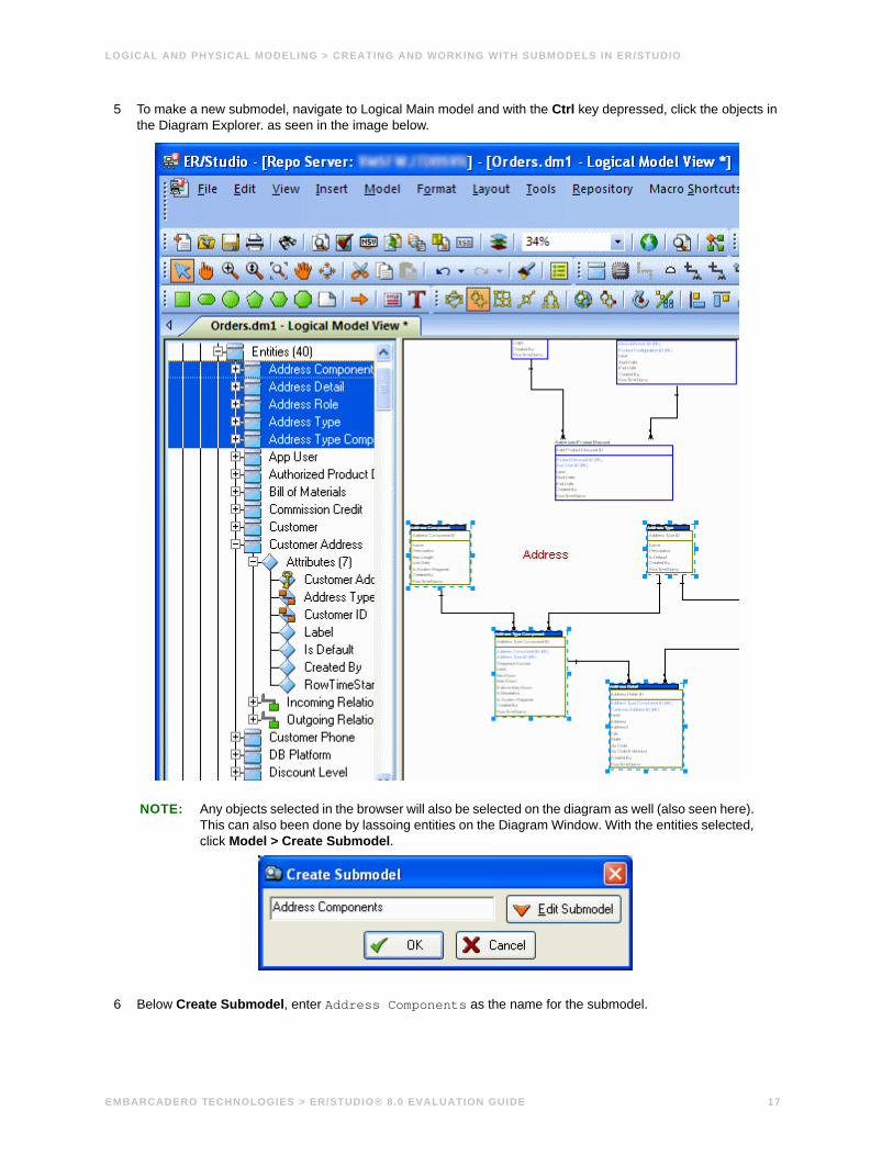
5 To make a new submodel, navigate to Logical Main model and with the Ctrl key depressed, click the objects in the Diagram Explorer. as seen in the image below.
NOTE: Any objects selected in the browser will also be selected on the diagram as well (also seen here). This can also been done by lassoing entities on the Diagram Window. With the entities selected, click Model > Create Submodel.
6 Below Create Submodel, enter Address Components as the name for the submodel.
EMBARCADERO TECHNOLOGIES > ER/STUDIO® 8.0 EVALUATION GUIDE 17

LOGICAL AND PHYSICAL MODELING > GENERATING PHYSICAL MODELS FROM A LOGICAL MODEL
7 Click OK.
ER/Studio creates the Address Components submodel.
What do the results look like and how do I navigate to the submodel? Once created, you’ll see the new submodel listed in the Diagram Explorer, denoted as a submodel by the magnifying glass over its folder, as in the case with Bill of Materials and the other submodels.Generating Physical Models from a Logical Model.
ER/Studio can generate as many physical models from a single logical model as desired. There are many ways to leverage multiple physical models in ER/Studio to help the design process. Examples of how multiple physical models are used are:
• Managing change in an existing application: Maintain independent development, test, and production physical model diagrams that represent specific databases.
• Migrating database applications: Use ER/Studio as an analysis and design hub for migrating database applications. Manage a physical model of the legacy source database application in addition to its new target physical model, which can be for an entirely new DBMS than originally maintained in the legacy database.
Generating Physical Models from a Logical ModelER/Studio can generate as many physical models from a single logical model as desired. There are many ways to leverage multiple physical models in ER/Studio to help the design process. Examples of how multiple physical models are used are:
• Managing change in an existing application: Maintain independent development, test, and production physical model diagrams that represent specific databases.
• Migrating database applications: Use ER/Studio as an analysis and design hub for migrating database applications. Manage a physical model of the legacy source database application in addition to its new target physical model, which can be for an entirely new DBMS than originally maintained in the legacy database.
Let’s generate a new physical model from a logical model in order to build a database. We’ll use the Orders.DM1 sample model.
1 Open your version of the Orders.DM1 sample model.
TIP: Use the steps shown in the last session to do so.
EMBARCADERO TECHNOLOGIES > ER/STUDIO® 8.0 EVALUATION GUIDE 18

LOGICAL AND PHYSICAL MODELING > GENERATING PHYSICAL MODELS FROM A LOGICAL MODEL
2 Select the Main Model and then click Model > Generate Physical Model.
ER/Studio invokes a step-by-step wizard to walk you through the process of generating a DBMS-specific physical model.
3 Name the new physical model, DB2 Physical Model and then select DB2 UDB for OS/390 8.x as the target DBMS to generate
4 Continue through the Generate Physical Model Wizard, which prompts very clear and concise questions about how you’d like your physical model to be generated.
NOTE: The wizard prompts you to customize items such as individual object selection, index assignment, default storage parameters, resolution of many-to-many relationships that may be in the logical model, naming conventions. A DBMS-specific validation check is also provided in this wizard.
TIP: The Quick Launch can store common settings so that an operation can be reused on this model or other any other models. You can reuse the settings on another model by choosing the Use File-Based Quick Launch Setting option when saving the Quick Launch information on the last page of the wizard.
EMBARCADERO TECHNOLOGIES > ER/STUDIO® 8.0 EVALUATION GUIDE 19

LOGICAL AND PHYSICAL MODELING > GENERATING PHYSICAL MODELS FROM A LOGICAL MODEL
5 To generate the new Physical Model, on the last page of the wizard, click Finish.
Now that a physical model has been generated from the logical model, feel free to navigate to specific objects via the Diagram Explorer (such as the CUSTMR table selected here, double click and view the physical details of the object such as DDL, Indexes, Partitions, and Storage.
New PhysicalModel in the Diagram Explorer
Double-clickCUSTMR, to invokethe Table Editorand view designdetails, such asthe DDL script.
EMBARCADERO TECHNOLOGIES > ER/STUDIO® 8.0 EVALUATION GUIDE 20
LOGICAL AND PHYSICAL MODELING > DENORMALIZING THE PHYSICAL MODEL
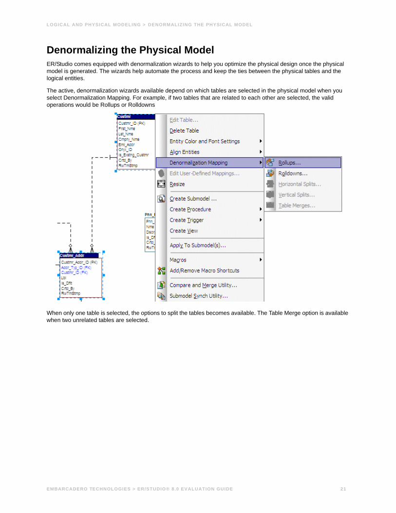
Denormalizing the Physical ModelER/Studio comes equipped with denormalization wizards to help you optimize the physical design once the physical model is generated. The wizards help automate the process and keep the ties between the physical tables and the logical entities.
The active, denormalization wizards available depend on which tables are selected in the physical model when you select Denormalization Mapping. For example, if two tables that are related to each other are selected, the valid operations would be Rollups or Rolldowns
When only one table is selected, the options to split the tables becomes available. The Table Merge option is available when two unrelated tables are selected.
EMBARCADERO TECHNOLOGIES > ER/STUDIO® 8.0 EVALUATION GUIDE 21

LOGICAL AND PHYSICAL MODELING > DENORMALIZING THE PHYSICAL MODEL
Let’s walk through an example of a denormalization operation using the generated physical model in previous session of this tutorial. We may want to reduce the overhead on the Custmr table by splitting it into two physical tables, Custmr_East and Custmr_West. Splitting the table can reduce the query time and provide opportunities to store the tables at different locations which could further reduce lookup time.
Before the operation, the Custmr table should look like:
1 Open the Orders1.dm1 model you modified and saved in the last session.
2 In the Diagram Explorer, right-click the Custmr table.
3 Click Denormalization Mapping > Horizontal Splits.
Notice that since only Custmr is selected, the only possible mappings are vertical and horizontal splits.
The Horizontal Table Split Wizard launches.
4 On Page 1, type 2 for the number of splits.
5 On Page 2, rename splits1 and 2 to Custmr_East and Custmr_West respectively.
EMBARCADERO TECHNOLOGIES > ER/STUDIO® 8.0 EVALUATION GUIDE 22

6 On Page 3, click Next.
We’ll keep all the relationships.
7 On Page 4, type a name and definition for the denormalization operation, select Reflect changes to original tables, and then click Finish.
Finished! After the split the Custmr table will be two physical tables that look like this:
The two tables are identical except for the name.
You can selectively choose which attributes are included in the resultant tables by using a vertical split.
The denormalization mapping is stored in the data model tree underneath the submodels. You can use this to undo the operation or see the history of what happened. ER/Studio tracks the before and after states of these operations. This comes in handy in the next section where we discuss the Where Used analysis that can be performed between the logical and physical models.
Finding out How an Entity Maps to the Physical ModelNow that we have performed a denormalization operation, the logical entity, Customer, essentially has become two physical tables, Custmr_East and Custmr_West. The ties between the logical and physical models are not lost. ER/Studio allows you to see what Customer in the logical model maps to in the DB2 physical model.
Let’s take a look at the Customer entity in the logical model.
1 In the Diagram Explorer, navigate back to the Customer entity in the Logical model
2 To start the Entity Editor, double-click the Customer entity.
EMBARCADERO TECHNOLOGIES > ER/STUDIO® 8.0 EVALUATION GUIDE 23

LOGICAL AND PHYSICAL MODELING > FINDING OUT HOW AN ENTITY MAPS TO THE PHYSICAL MODEL
3 Click the Where Used tab.
Once the tree is expanded, you can see the lineage of what has happened to the object. Notice that Custmr_East and Custmr_West are listed as physical implementations of the Customer entity. The denormalization mapping object from the data model explorer tree is visible to see how the end result was achieved.
The Where Used tab also displays the submodel usage of a particular entity within the logical or physical model. This allows you to see which business areas the entity belongs to.
NOTE: The Where Used information is also available for attributes and columns.
ConclusionIn this session, you have seen how incredibly quick and easy it is to:
• Build a logical data model from scratch.
• Create a new submodel view to understand how to model on specific parts of a larger Main Model.
• Generate a physical model from a logical database in preparation for building a new database.
• Denormalize objects in the physical model.
• View the mappings between the logical and physical models using the Where Used tabs.
For more assistance on these issues, please feel free to refer to the ER/Studio Help and the review the Logical Modeling Features and Physical Modeling Features topics that describe processes such as
• SQL Generation.
• Merging changes between logical and physical models.
EMBARCADERO TECHNOLOGIES > ER/STUDIO® 8.0 EVALUATION GUIDE 24

DOCUMENTING AN EXISTING DATABASE > GENERATING AN HTML INTRANET DICTIONARY REPORT
Documenting an Existing DatabaseOne of ER/Studio’s most powerful applications is that of a documentation generator to communicate complex databases and associated metadata to the Enterprise. ER/Studio is equipped with extensive report generation capabilities:
• HTML Report Generation: Instantaneous generation of an HTML-based Web site designed to provide simple navigability through data models and model metadata using standard browsers such as Microsoft’s Internet Explorer or Netscape Navigator.
• RTF Report Generation: Instantaneous documentation generation compatible with applications like Microsoft Word.
In the exercise below, we’ll reverse-engineer an existing database and generate an HTML report for distribution and navigation to those who depend upon the information about the data model, but who may not be permitted to connect to the database for security or organizational reasons.
Generating an HTML Intranet Dictionary Report
PRE-REQUISITE: This exercise assumes that you can connect to an existing database in order to document it. Please refer to “Reverse-Engineering an Existing Database” in ER/Studio’s Help for explicit setup details if needed. If you cannot connect to an existing database, you can still generate documentation from the installed sample models. Skip steps step 1 through step 7 below involved in reverse-engineering and begin at step 8 after opening a sample model included with ER/Studio.
1 Click File > New.
2 Select Reverse-engineer an existing database.
3 Click Login.
You can reverse engineer the database from either an ODBC datasource or via Native RDBMS client connectivity. In this example, Native Connectivity to Microsoft SQL Server will be demonstrated.
EMBARCADERO TECHNOLOGIES > ER/STUDIO® 8.0 EVALUATION GUIDE 25

DOCUMENTING AN EXISTING DATABASE > GENERATING AN HTML INTRANET DICTIONARY REPORT
4 Type the relevant connectivity information such as the datasource name, and user name and password and then click Next.
EMBARCADERO TECHNOLOGIES > ER/STUDIO® 8.0 EVALUATION GUIDE 26

DOCUMENTING AN EXISTING DATABASE > GENERATING AN HTML INTRANET DICTIONARY REPORT
5 Walk through the Reverse Engineer Wizard selecting the objects, options, and layout preferences for the model.
EMBARCADERO TECHNOLOGIES > ER/STUDIO® 8.0 EVALUATION GUIDE 27

DOCUMENTING AN EXISTING DATABASE > GENERATING AN HTML INTRANET DICTIONARY REPORT
EMBARCADERO TECHNOLOGIES > ER/STUDIO® 8.0 EVALUATION GUIDE 28
DOCUMENTING AN EXISTING DATABASE > GENERATING AN HTML INTRANET DICTIONARY REPORT
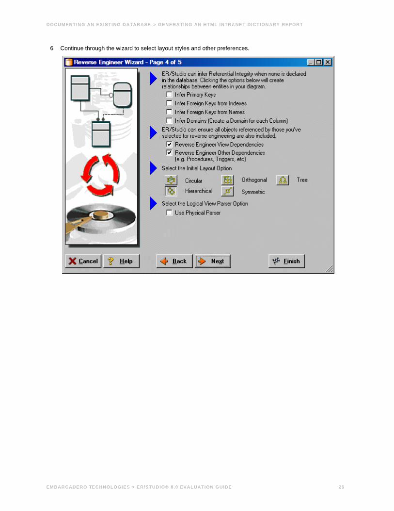
6 Continue through the wizard to select layout styles and other preferences.
EMBARCADERO TECHNOLOGIES > ER/STUDIO® 8.0 EVALUATION GUIDE 29

7 Click Finish and ER/Studio reverse engineers your database!
Once reverse engineering of your database is complete, let’s generate a complete HTML report of the database for others in your organization to review….
8 In the Diagram Explorer, select the Physical Main Model.
EMBARCADERO TECHNOLOGIES > ER/STUDIO® 8.0 EVALUATION GUIDE 30
DOCUMENTING AN EXISTING DATABASE > GENERATING AN HTML INTRANET DICTIONARY REPORT
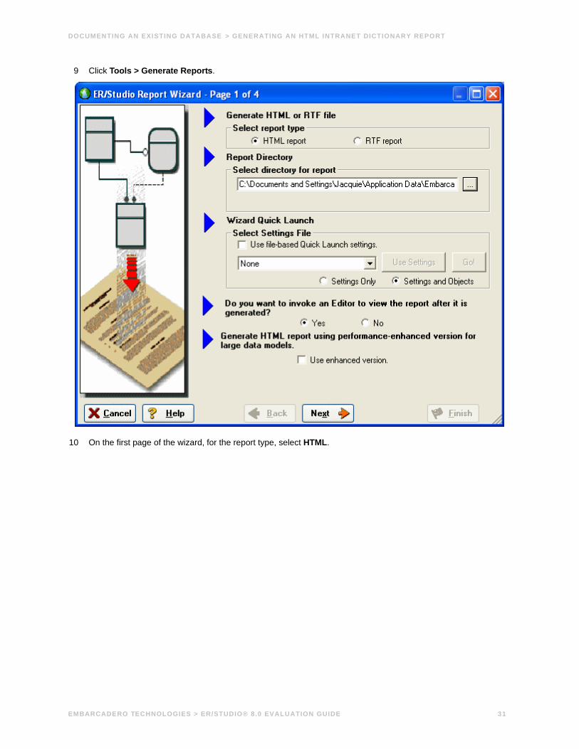
9 Click Tools > Generate Reports.
10 On the first page of the wizard, for the report type, select HTML.
EMBARCADERO TECHNOLOGIES > ER/STUDIO® 8.0 EVALUATION GUIDE 31
DOCUMENTING AN EXISTING DATABASE > GENERATING AN HTML INTRANET DICTIONARY REPORT
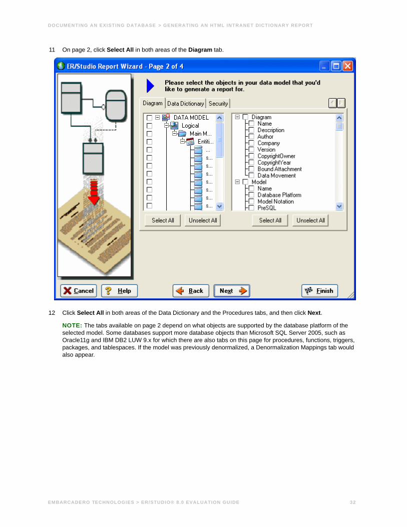
11 On page 2, click Select All in both areas of the Diagram tab.
12 Click Select All in both areas of the Data Dictionary and the Procedures tabs, and then click Next.
NOTE: The tabs available on page 2 depend on what objects are supported by the database platform of the selected model. Some databases support more database objects than Microsoft SQL Server 2005, such as Oracle11g and IBM DB2 LUW 9.x for which there are also tabs on this page for procedures, functions, triggers, packages, and tablespaces. If the model was previously denormalized, a Denormalization Mappings tab would also appear.
EMBARCADERO TECHNOLOGIES > ER/STUDIO® 8.0 EVALUATION GUIDE 32

DOCUMENTING AN EXISTING DATABASE > GENERATING AN HTML INTRANET DICTIONARY REPORT
13 On page 3 below Submodel Image Options, click Select All.
TIP: In the Logo and Link Options, you can choose to replace ER/Studio’s default Embarcadero Technologies logo in favor of your own corporate logo (and Hyperlink).
Because HTML formatting can be included in object definitions, you can also choose to preserve the formatting specified on the Definitions tab of the various object editors.
14 Click Next to advance to Page 4 of 4, and then click Finish.
ER/Studio then begins the report publication process and launch the default browser so you can review the report.
EMBARCADERO TECHNOLOGIES > ER/STUDIO® 8.0 EVALUATION GUIDE 33

DOCUMENTING AN EXISTING DATABASE > GENERATING AN HTML INTRANET DICTIONARY REPORT
15 Finished!
Start navigating the report via your browser. Navigation will perform exactly as it does when you are using ER/Studio! Expand the tree to find Model Image and click on it (see below). You will see a read-only version of your data model (as seen below). Use the Explorer to navigate to ANY metadata you want or select the entities and relationships in the model image to jump to their information.
ConclusionIn this session, you have learned how to:
• Connect to and reverse-engineer an existing database with ER/Studio.
• Document a database in seconds by ER/Studio’s automatic HTML documentation publication facility.
For more assistance on Reporting, please feel free to refer to ER/Studio’s Help and review the Reports section.
EMBARCADERO TECHNOLOGIES > ER/STUDIO® 8.0 EVALUATION GUIDE 34

DOCUMENTING DATA LINEAGE > CREATE A DATA FLOW
Documenting Data LineageThe Data Lineage features of ER/Studio enables you to document the movement of data from point A to point B (and any intermediate steps in between) is sometimes referred to as ETL (Extraction, Transformation and Load). Points A and B can be anything from flat files, databases, XML, Access, Excel, etc.. This is sometimes referred to as source and target mapping. A model produced in ERStudio can represent any point along the way. Data Architects need to ability to specify the source or target of data down to the column-level. Along with the metadata that defines the source and target mapping are rules for how the data is manipulated along the way.
This section will help you document the data lineage of your systems. It is comprised of the following tasks which correspond to the general ETL workflow:
• Create a Data Flow
• Create a Data Movement Rule
• Define Legacy Source and Target Systems
• Create a Data Lineage and Transformation Visualization
Create a Data FlowThe Data Flow organizes and encapsulates one data transformation and the source tables and columns used in the transformation to produce the target data. Multi-tiered mappings are possible and there can be multiple transformations involving different columns between two tables as illustrated below.
EMBARCADERO TECHNOLOGIES > ER/STUDIO® 8.0 EVALUATION GUIDE 35

Create a Data Lineage Data Flow1 Click File > Open and select the GIMB.DM1 diagram in the Sample Models directory.
2 Click the Data Lineage tab at the bottom of the application window.
You are prompted to create a Data Lineage Data Flow.
3 Click Yes.
If this is not the first time you click the Data Lineage tab after opening a diagram, from the Data Lineage explorer, right-click the Data Flows node and then click Create Data Flow.
4 Enter a Data Lineage Data Flow name and then click OK.
NOTE: The name that appears in the diagram title tab at the top of the application window is appended with : task name, when you click a task in the Data Lineage explorer, such as GIMDB.DM1 - Data Flow Model View: Broker*.
The Data Flow has been created.
Create a Data Movement Rule Data Movement rules describe how source and target tables and entities are related. You can relate source data to one or more tables and entities in the same model, the active diagram, or to tables imported from legacy systems. The rules defined here are used on the at the table level on the Data Lineage tab of the entity and table editors.
EMBARCADERO TECHNOLOGIES > ER/STUDIO® 8.0 EVALUATION GUIDE 36

DOCUMENTING DATA LINEAGE > CREATE A DATA MOVEMENT RULE
Create a data movement rule1 On the Data Lineage tab, right-click Data Movement Rules and choose New Data Movement Rule.
2 Complete the Data Movement Rule editor as required and then click OK to exit the editor.
TIP: Once created, you can edit the Data Movement rule by double-clicking it to launch the Data Movement Rule editor.
The following describes options that are not self-explanatory:
Rule Information tab
• Rule Name: Enter a name that indicates the operation and objects acted on, depending on the specifics of your binding definition.
• Rule Type: Select a generic movement rule type that best describes the data movement.
• Rule Text: Document your data movement plan here, perhaps adding instructions or contingency plans.
Binding Information tab
Select the object classes and/or specific objects to which you want to bind this attachment. You can override this setting using the Data Lineage tab of the entity or table editor.
EMBARCADERO TECHNOLOGIES > ER/STUDIO® 8.0 EVALUATION GUIDE 37

DOCUMENTING DATA LINEAGE > DEFINE EXTERNAL SOURCE AND TARGET SYSTEMS
Define External Source and Target SystemsData sources can originate from models in the active diagram (local models) or from an external source that are either imported into the active diagram or created on the Data Lineage tab. A data source can be imported from *.dm1 files, *.dt1 files, database or a SQL files, flat files, and other common application files. The following describes how to import metadata from an external source.
NOTE: Source data imported through the Data Lineage tab only includes information such as table and column name, datatype, nillability, primary key, and column definitions. To obtain more details, reverse engineer the database or import it into ER/Studio using the Metadata Wizard.
Import external source or target data1 From the Data Lineage tab, expand the Data Sources node.
2 Right-click Other Sources and choose New Source.
3 Complete the Data Source/Target Properties dialog as required and then click OK to exit the editor.
The following describes options that are not self-explanatory:
EMBARCADERO TECHNOLOGIES > ER/STUDIO® 8.0 EVALUATION GUIDE 38

DOCUMENTING DATA LINEAGE > CREATE A DATA LINEAGE AND TRANSFORMATION VISUALIZATION
General tab
• General Properties
• Name: The name you give it here will be displayed as a data source in the physical model.
• Type: Select the source/target type. This setting affects available options in the Connectivity group. For example, select Relational for a DBMS such as MySQL.
• Connectivity Properties
• Host, Server/Service, Port: For connecting to an external DBMS. For an existing ER/Studio physical model, leave blank.
• DBMS Type, Version, Location/Path, File Type, Encoding: These settings depend on the Type selected above.
Model Usage tab
This is a read-only display of the source or target defined on the General tab. Ensure that it matches your intentions.
Create a Data Lineage and Transformation Visualization1 To create the data source or transformation input tables, expand Data Sources > Local Models > Logical >
Entities and then drag and drop the Broker and Investment tables onto the Data Lineage window.
2 To create the data target or transformation output tables, navigate to Data Sources > Local Models > GIM_DW and then drag and drop the Broker table onto the Data Lineage window.
3 To obtain the Transformation insertion tool, right-click an empty space in the Data Lineage window and then click Insert Transformation.
4 To insert the transformation, click in the Data Lineage window between the source and target data sources and then right-click to drop the Transformation Insertion tool.
EMBARCADERO TECHNOLOGIES > ER/STUDIO® 8.0 EVALUATION GUIDE 39

DOCUMENTING DATA LINEAGE > CREATE A DATA LINEAGE AND TRANSFORMATION VISUALIZATION
5 Right-click an empty space of the Data Lineage window and then click Insert Data Stream.
TIP: Transformation and Data Flow tools are also available on the toolbar. Mouse over the tools to find the tool you need.
6 Click an input and then click the transformation object. Repeat as many times as necessary to link all the inputs to the transformation object.
7 Click the transformation object and then click an output.
TIP: If the Inputs and Outputs don’t display in the diagram as they do in the illustration above, click View > Diagram and Object Display Options > Transformation and then click Input and Output Columns.
8 To define which columns should be used in the transformation and any transformation rules, double-click the new transformation to open the Transformation Editor.
EMBARCADERO TECHNOLOGIES > ER/STUDIO® 8.0 EVALUATION GUIDE 40

9 Complete the Transformation Editor as required and then click OK to exit the editor.
You’re done! Now you can more easily share your ideas with your colleagues!
TIP: Once the Data Flow is created, you can double-click it to change its name, or double click a transformation or component to change its properties.
The following describes options in the Transformation Editor that are not self-explanatory:
Columns tab
• Inputs: Click the ellipsis (...) button to choose the source data to be transformed in this task.
• Outputs: Click the ellipsis (...) button to choose the outputs resulting from the transformation.
Definition tab
• Business: Describe the transformation for your audience.
• Code: Enter the code that will perform the transformation, such as a SELECT statement, of a VB Basic or Java Script function or procedure.
Rules tab
These are the rules from the Data Movement Rules node of the Data Lineage explorer.
NOTE: You can delete or edit an input or output column by double-clicking the transformation in the Data Lineage window, clicking the ellipsis in the Transformation Editor and then deselecting the column you want to remove.
EMBARCADERO TECHNOLOGIES > ER/STUDIO® 8.0 EVALUATION GUIDE 41

DOCUMENTING DATA LINEAGE > CREATE A DATA LINEAGE AND TRANSFORMATION VISUALIZATION
Attachments tab
Lets you bind an external piece of information, or attachment to the transformation. You can also remove an attachment from an object, override an attachment binding’s default value, or change a bound attachment’s position. To override the value of the attachment you have moved to the Selected Attachments grid, double-click the Value field of the target attachment. ER/Studio opens the Value Override Editor or a list depending on the attachment datatype. Attachments are created in the Attachments folder of the Data Dictionary and must be applied to the default before they will display on this tab.
EMBARCADERO TECHNOLOGIES > ER/STUDIO® 8.0 EVALUATION GUIDE 42

DIAGRAM NAVIGATION AND AESTHETICS > DIAGRAM NAVIGATION
Diagram Navigation and Aesthetics The fruit a powerful data modeling product like ER/Studio bears are its diagrams. To assist with the creation of presentation-quality diagrams that are easy to navigate and are aesthetically pleasing, ER/Studio offers progressive diagram Auto Layout and Navigation utilities that also helps you to clean up complex diagrams. Modelers should spend time solving complex database or business data model problems, not forcing boxes and lines to look a certain way.
Diagram NavigationTo demonstrate some of ER/Studio’s layout and navigation utilities, we’ll import a sample SQL script provided with ER/Studio.
1 Close any files you have open.
2 Click File > New.
EMBARCADERO TECHNOLOGIES > ER/STUDIO® 8.0 EVALUATION GUIDE 43

DIAGRAM NAVIGATION AND AESTHETICS > DIAGRAM NAVIGATION
3 Select Import Model From: and then in the import list, click SQL File.
NOTE: The ERX File choice indicates the products ability to import Computer Associates ERwin 3.5.2 ERX files, From External Metadata launches the MetaWizard to import from alternative sources.
The Import Database SQL File dialog appears:
4 To the right of Select a Database SQL File click the folder icon, click IBM DB2 OS390.SQL, and then click Open.
The full path to this file is:
Windows XP:C:\Documents and Settings\<user>\Application Data\Embarcadero\ERStudio\SQLCode
Windows Vista: C:\Users\<user>\AppData\Roaming\Embarcadero\ERStudio\SQLCodeSample
5 In the Select the target database platform list, click IBM DB2 UDB for OS /390 9.x.
EMBARCADERO TECHNOLOGIES > ER/STUDIO® 8.0 EVALUATION GUIDE 44

DIAGRAM NAVIGATION AND AESTHETICS > DIAGRAM NAVIGATION
6 Click OK.
Finished! Once the SQL Script is finished importing (as depicted below) the following items will assist you in leveraging a variety of Auto Layout and Navigation Features.
• Layout and Alignment Toolbar: Use any of the 4 Auto Layout styles to change the layout of the diagram with the click of a button. These are all entirely customizable styles as well via the Layout Properties pages launched by clicking Main menu > Layout > Layout Properties.
• Diagram Explorer: Click on any object in the Diagram Explorer and it will automatically be selected in the diagram and focused in both the Zoom and Overview windows.
• Overview Window: Use this window as a thumbnail of your model to pan the entire model or zoom in and out. It can also pan and zoom the diagram if grabbed or sized. If the Overview Window is not already visible, press the F9 key to activate.
• Zoom Window: Use this window as a magnifying glass to enlarge any diagram objects under your mouse cursor. You can also press SHIFT+F8 to freeze the zoom window to keep a single object frozen while you continue to pan around the diagram. If the Zoom Window is not already visible, press F8 to activate it.
Layout and Alignment Toolbar
Diagram Explorer
Zoom Window
Overview WIndow
EMBARCADERO TECHNOLOGIES > ER/STUDIO® 8.0 EVALUATION GUIDE 45

Diagram Aesthetics One of the tremendous benefits of building data models is the wide range of audiences that can realize value from them. Part of this relies on what information is displayed on the diagram. Depending on the audience you may want to limit or expand what is displayed. For example, developers may benefit from looking at a model that displays data type, null option, and unique and non-unique index information, while business analysts may just need the entity name and the definition. ER/Studio offers many display properties that can be customized exactly for this purpose.
Continuing with the previous section, we’ll use the DB2 model that was built to demonstrate some of the ways to customize the appearance of the model.
We’ll use the Diagram and Object Display Options dialog on the Diagram toolbar to customize the view of the logical and physical models.
NOTE: You can use the Colors & Fonts tool to customize the look and feel further of each model.
Setting the Logical Model Display1 Select the logical model and then on the Diagram Toolbar, click the Diagram and Objects Display Options
tool
2 In the Diagram And Object Display Options dialog, click the Entity tab, and then in the Display Level are, select Entity.
3 Click OK.
NOTE: Only entity names are displayed for each entity. You may also want to re-layout the diagram since the entity sizes have changed.
EMBARCADERO TECHNOLOGIES > ER/STUDIO® 8.0 EVALUATION GUIDE 46

DIAGRAM NAVIGATION AND AESTHETICS > DIAGRAM AESTHETICS
Setting the Physical Model Display1 Select the physical model and then on the Diagram toolbar, click the Diagram and Objects Display Options
tool.
2 In the Diagram And Object Display Options dialog, click the Table tab.
3 In the Display Level area, select Physical Attribute Ordering.
4 In the Available Options are, select the specific properties you want to display.
EMBARCADERO TECHNOLOGIES > ER/STUDIO® 8.0 EVALUATION GUIDE 47

DIAGRAM NAVIGATION AND AESTHETICS > DIAGRAM AESTHETICS
5 Click OK.
The model should now display more details for the physical model, as seen below.
NOTE: Since the objects sizes changed, you may want to change the model layout using one of ER/Studio’s advanced layout engines. You can also customize the default display properties for new models by clicking Tools > Options, and then selecting the desired options on the Display tab.
ConclusionIn this session, you have learned how to:
• Import an SQL file and allow ER/Studio to automatically create a diagram.
• Use a variety of auto layout and navigation tools to enhance the aesthetic experience of the diagram and overall improve the data model navigability.
• Customize the display of both the logical and physical models.
EMBARCADERO TECHNOLOGIES > ER/STUDIO® 8.0 EVALUATION GUIDE 48

IMPORTING AND EXPORTING METADATA > IMPORTING METADATA
Importing and Exporting MetadataThe MetaWizard allows you to import and export metadata from a wide spectrum of sources and targets. Various metadata formats are supported that provide connectivity to environments such as XML Schemas and DTDs, OMG’s CWM-XMI, and business intelligence repositories such as Business Objects, Cognos, DB2 Cube Views, and various UML and data modeling tools.
NOTE: The MetaWizard is a separately licensed module. For evaluation purposes the Import Bridge is enabled during the install, but the Export Bridge is not. Contact [email protected] to enable the Export Bridge for evaluation.
Importing MetadataLet’s walk through an example of how to build a model from a specific metadata source. In this case we’ll use OMG CWM XMI 1.1, one of the popular formats used by various modeling tools.
1 Close any open files.
2 To launch the Import MetaWizard, click File > Import File > From External Metadata.
3 To select the external metadata:.In the Type list, click OMG CWM 1.xXMI 1.x.
• Next to From, click the folder icon and browse to the Sample Models directory, select OrangeMart (XMI).xml, and then click Open.
The sample models are located at:
• Windows XP:C:\Documents and Settings\All Users\Application Data\Embarcadero\ERStudio_X.X\Sample Models
EMBARCADERO TECHNOLOGIES > ER/STUDIO® 8.0 EVALUATION GUIDE 49

• Windows Vista:C:\ProgramData\Embarcadero\ERStudio_X.X\Sample Models
Each environment has specific versions that determine how the metadata is translated. When importing models or metadata from another source of your own, ensure you select appropriate platform and version.
EMBARCADERO TECHNOLOGIES > ER/STUDIO® 8.0 EVALUATION GUIDE 50

IMPORTING AND EXPORTING METADATA > IMPORTING METADATA
4 Click Next, click through page 2, and then on page 3 click Finish
By default the MetaWizard preforms a basic consistency check of the file imported and reports any inconsistencies on page 2 of the wizard.
The MetaWizard builds a logical and physical model based on the source metadata.
5 Click File > Save and then specify a filename.
Please keep this model for use in Dimensional Modeling of this guide.
NOTE: In some cases the layout will not import from the source metadata. If this happens you can use one of ER/Studio’s advanced layout engines as described in an earlier section.
EMBARCADERO TECHNOLOGIES > ER/STUDIO® 8.0 EVALUATION GUIDE 51

IMPORTING AND EXPORTING METADATA > EXPORTING METADATA
Exporting MetadataER/Studio can export metadata in the same formats from which it can import. The difference is that metadata can be exported from the entire diagram by clicking File > Export or from any of the submodels including the main model by right-clicking the submodel.
Let’s walk through an example of exporting. We’ll use the model that was built from the XMI file. In this example we want to export the diagram metadata to Business Objects so the business intelligence folks can use the metadata to generate reports.
NOTE: You need a separate license for the Export Bridge to continue with this exercise.
1 Click File > Export File > Export Diagram Metadata.
This launches the Export Bridge
2 To select the output type
• In the Type list, click Business Objects Data Integrator.
• Next to Save To, click the folder icon and browse to a file location for the XML file, enter a filename, and then click OK.
EMBARCADERO TECHNOLOGIES > ER/STUDIO® 8.0 EVALUATION GUIDE 52

IMPORTING AND EXPORTING METADATA > EXPORTING METADATA
3 Click Next.
This will run a check on the exported metadata.
4 Click Finish.
This will save the file to the specified location. We will use this file in the next tutorial.
ConclusionIn this session we’ve explored the metadata management capabilities of ER/Studio, specifically how to:
• Import metadata from a wide range of sources to produce a logical and physical model.
• Export metadata to an equally wide range of formats so that metadata can be shared with other groups within your organization.
EMBARCADERO TECHNOLOGIES > ER/STUDIO® 8.0 EVALUATION GUIDE 53

DIMENSIONAL MODELING > OVERVIEW OF DIMENSIONAL NOTATION
Dimensional ModelingER/Studio allows you to model dimensional structures such as star and snowflake schemas that can be leveraged for data warehouses, data marts, and OLAP. ER/Studio’s dimensional notation helps you to visualize and build these complex models by using icons for the various table types, and enforcing rules specific to dimensional modeling standards. This session will help you construct a dimensional model and walk you through some of the aspects inherent to dimensional notation.
Overview of Dimensional NotationFirst, let’s create a dimensional model. There are a number of ways you can designate a model as dimensional.
Designating a Model as DimensionalIf you are creating a new model you can designate the model as dimensional in one of the following dialogs:
• On Page 5 of the Reverse Engineer Wizard.
Click File > New, select Reverse-engineer en existing database. Login to the database, click Next to page 5, and then in answer to What type of Physical Model is this?, select Dimensional.
• In the SQL Import dialog.
Click File > Import file from SQL file, and then in answer to What type of Physical Model is this?, select Dimensional.
• On Page 1 of the Generate Physical Model Wizard.
Right-click the Logical model, select Generate Physical Model, and then in answer to What type of Physical Model is this, select Dimensional
If you have an existing physical model, you can change the type in Model > Model Options. For the purpose of this session, we will use the model created from the XMI file in the Import Metadata session. If you skipped to that session, go back to Importing and Exporting Metadata and walk through the Import Metadata section.
Since we already have an existing model, we’ll just change the notation.
1 Click File > Open, navigate to the physical model you saved in Importing Metadata, and then click Open.
2 Right-click the physical model and then click Model Options.
EMBARCADERO TECHNOLOGIES > ER/STUDIO® 8.0 EVALUATION GUIDE 54
DIMENSIONAL MODELING > OVERVIEW OF DIMENSIONAL NOTATION
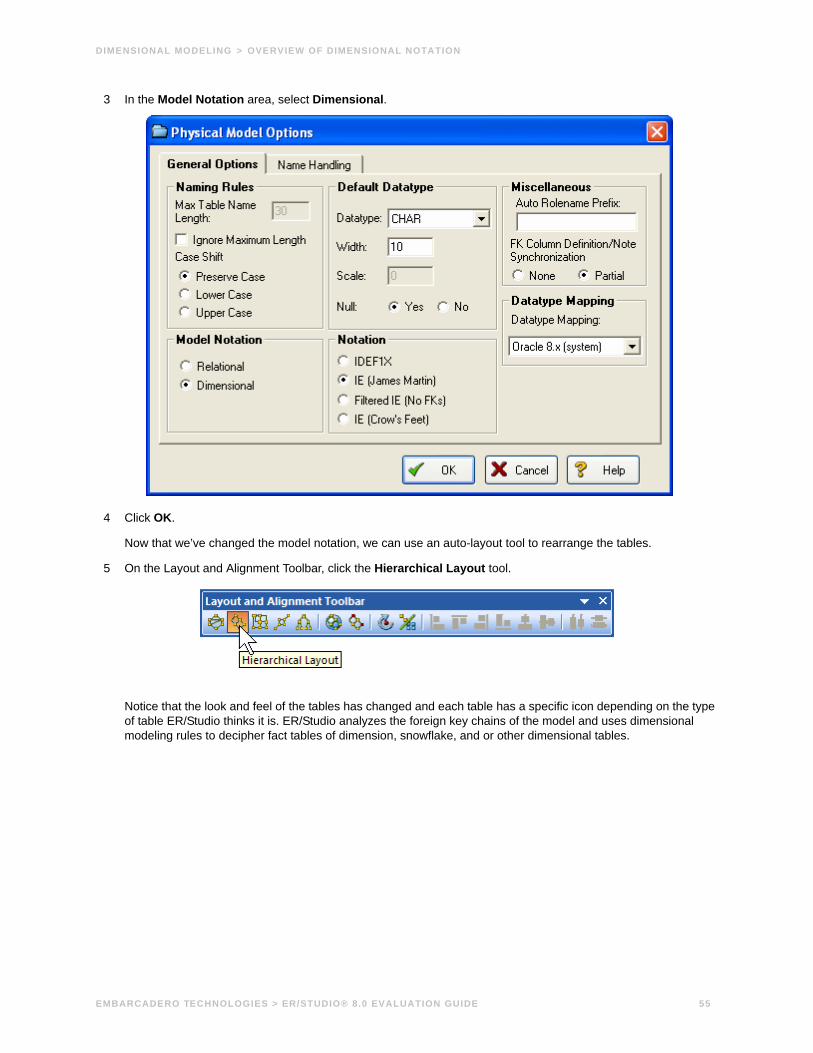
3 In the Model Notation area, select Dimensional.
4 Click OK.
Now that we’ve changed the model notation, we can use an auto-layout tool to rearrange the tables.
5 On the Layout and Alignment Toolbar, click the Hierarchical Layout tool.
Notice that the look and feel of the tables has changed and each table has a specific icon depending on the type of table ER/Studio thinks it is. ER/Studio analyzes the foreign key chains of the model and uses dimensional modeling rules to decipher fact tables of dimension, snowflake, and or other dimensional tables.
EMBARCADERO TECHNOLOGIES > ER/STUDIO® 8.0 EVALUATION GUIDE 55

DIMENSIONAL MODELING > OVERVIEW OF DIMENSIONAL NOTATION
The illustration below gives an overview of dimensional notation.
Snowflake Table
Dimension Table
Dimension Typedisplay information
Icons in theDiagram Explorercorrespond totable type inthe model. Thesame icon willappear in theupper-leftcorner of eachtable.
EMBARCADERO TECHNOLOGIES > ER/STUDIO® 8.0 EVALUATION GUIDE 56

DIMENSIONAL MODELING > WORKING IN A DIMENSIONAL MODEL
Working in a Dimensional ModelNotice in the picture above that ER/Studio guessed that Product_Patent is a fact table, Approved_Product is a dimension table and the parent tables of Approved_Product are snowflakes. This is because Product_Patent has no child tables, Approved_Product is a parent of Product_Patent, and the parent tables of Approved_Product are two relationships away from the perceived fact table. Analyzing this a little further, it looks like Approved_Product is actually the fact table, Product_Patent could be a bridge to another fact table, and the parents of Approved_Product are actually qualifiers of Approved_Product or dimensions. The table type can be changed to override how ER/Studio originally interpreted the table.
Let’s walk through an example. With the physical model from the previous example selected, let’s edit the Approved_Product table.
1 To open the Table Editor, double-click the Approved_Product table.
2 Click the Dimensional tab.
3 In the Dimensional Model Table Type list, click Fact.
TIP: There are other dimensional model type tables such as Bridge and Hierarchy Navigation. Click the list to see the other table types.
4 Ensure the Override Automatic Designation option is selected.
5 Select the Run Automatic Table Type Identification option.
6 Click OK.
TIP: You can change the designation of a table without affecting related tables by deselecting the Run Automatic Table Type Identification option.
EMBARCADERO TECHNOLOGIES > ER/STUDIO® 8.0 EVALUATION GUIDE 57

DIMENSIONAL MODELING > WORKING IN A DIMENSIONAL MODEL
The result is that Approved_Product becomes the Fact table. The parent tables of Approved_Product will all become dimension tables and the Product_Patent table will be designated as undefined. As another exercise, select another dimension table and change the type of dimension depending on the desired data refresh rate as in the following illustration.
Icons in the Diagram Explorer havechanged to reflect the dimensional model designation.
Dimensional Tables
Now designatedas a Fact table
Dimensional type set to Type 1. Fixed is the default.
Manually set to a Bridge table
EMBARCADERO TECHNOLOGIES > ER/STUDIO® 8.0 EVALUATION GUIDE 58

AUTOMATING TASKS > CREATING MACROS
Automating TasksER/Studio is equipped with a highly documented Automation Interface. The automation interface is driven by the Sax Basic language (a derivative of the Visual Basic for Applications language) and serves many purposes, fundamentally for enabling you to customize ER/Studio through an application interface
There are two main reasons to employ the Automation Interface:
• Automate Routine Tasks – Automate tedious, routine modeling tasks or customize ER/Studio to enforce modeling practices in your organization. For example, you can write a macro that will automatically colorize child tables that contain propagated foreign keys. Or, you can write a macro to automatically insert a specific name and primary key into new entities as they are created.
• Collaborate with other applications – Your ER/Studio models contain valuable metadata that you can access from applications such as Microsoft Excel, Access, and Outlook. Using ER/Studio's automation interface, you can collaborate with any external application that has an exposed API or its own automation interface.
In this walk-through, we’ll demonstrate an example of how to leverage ER/Studio’s automation interface to dramatically increase modeler productivity. You will not be writing any Sax Basic (VBA) code in this walk-through. You will running a macro that is included with the product. You can write your own macros using the Sax Basic Integrated Development Environment included in ER/Studio.
Creating MacrosUsing the Sax Basic integrated development environment, you can expand upon the functionality offered in the sample macros provided or create macros to automate model development and maintenance.
To access the Sax Basic development environment, click Tools > Basic Macro Editor.
TIP: The automatic appearance of lists as you type, allows you to select and insert ER/Studio Automation Objects. After inserting an object, you can get information about the object by selecting it and then clicking the Browse Object tool on the application toolbar.
EMBARCADERO TECHNOLOGIES > ER/STUDIO® 8.0 EVALUATION GUIDE 59

AUTOMATING TASKS > USING MACROS TO AUTOMATE THE MODELING PROCESS
Using Macros to Automate the Modeling Process You can use Visual Basic macros to speed development and enforce the re-use of metadata.
In this example, we’ll be leveraging macros provided with the product to demonstrate powerful Automated modeling activities users can benefit from.
1 Close all open diagrams.
2 Click File > New and then select Draw a New Data Model.
3 In the Diagram Explorer, click the Macros tab.
4 In the Modeling Productivity Macros, locate the Auto-Create Data Dictionary macro.
5 Right-click the Auto Create Data Dictionary macro and then click Run Macro.
Running this macro will create a set of Domains in the Data Dictionary which the next macro run will leverage. (For more information on Domains, see Logical and Physical Modeling).
6 With the set of Domains now ready, create an entity on the Diagram Window.
TIP: For a refresher on creating an entity, see Using Data Dictionary Domains to Populate New Entity.
EMBARCADERO TECHNOLOGIES > ER/STUDIO® 8.0 EVALUATION GUIDE 60

AUTOMATING TASKS > USING MACROS TO AUTOMATE THE MODELING PROCESS
7 Name the entity, Person.
You do not need to implement any attributes for the Person entity at this time.
8 Select the Person entity and in the Modeling Productivity Macros folder, right-click Add Base Attributes To Person Entity and then click Run Macro.
NOTE: The macro automatically created all of the attributes for Person entity for you!
You have just:
• Saved the effort of manually typing these standard attributes into selected entities that require them.
• Bound all the new attributes to Domains for proper standard enforcement.
You can customize these macros in any way you choose! This example merely stresses how to increase the productivity of modelers to automate repetitive tasks such as ensuring entities conform to the same standard set of attributes. Feel free to explore the other macros we’ve included for you as well to see how they can increase your productivity.
ConclusionIn this session, you have learned how to:
• Access the Basic Macro Editor to create your own macros from scratch.
• Select the Macro tab of the Explorer Browser and launch sample macros included with ER/Studio to help increase modeler productivity.
For more assistance on the Automation Interface, please feel free to refer to ER/Studio’s Help and review the section on Automation Interface.
EMBARCADERO TECHNOLOGIES > ER/STUDIO® 8.0 EVALUATION GUIDE 61

COLLABORATIVE MODELING > GETTING STARTED WITH ER/STUDIO ENTERPRISE
Collaborative ModelingER/Studio Enterprise includes a server-side component to ER/Studio designed to distribute work across modeling team members in a safe and controlled way, facilitating a real-time collaborative modeling environment and increasing productivity for teams out of the box. The solution implements utilities and features that enable concurrent modeling, version management for model and model objects, establishment of continually reusable data elements, and more. The secure, scalable environment is fully integrated with the current, natural workflow in ER/Studio.
This portion of the guide is intended to give a brief overview and walkthrough of ER/Studio Enterprise. It will start with the install and configuration of the Repository and continue on to include inserting a diagram into the Repository, working with the diagram in the Repository, versioning the diagram, sharing and reusing objects across diagrams and finally applying security to your diagrams. It is intended as an introduction of the Repository. For more information please refer to the Repository section of ER/Studio’s Help or contact Technical Support at [email protected] or call (415) 834 3131 x2.
Getting Started with ER/Studio Enterprise
Downloading and InstallingTo evaluate the collaborative modeling benefits of ER/Studio Enterprise, you will need to download and install a separate installation executable. You can download the Repository installation executable from the Embarcadero Web site at:
www.embarcadero.com/downloads/download.html
You need to download the ER/Studio Enterprise zip file or the ER/Studio Standard Upgrade to Enterprise executable.
ER/Studio Enterprise requires installation on an RDBMS of your choice: IBM DB2 UDB, Oracle, Sybase ASE or Microsoft SQL Server. Two components will be installed: the server and the database. The server machine requires the chosen database client utilities to be installed in advance so that the server can initially build and subsequently connect and communicate with the database thereafter.
• For more comprehensive installation instructions, please refer to the Installation section of ER/Studio’s Help.
• For information regarding database sizing, Repository server requirements and Architecture, refer to Repository Care and Maintenance section under the Repository section of the ER/Studio Online Help.
Installation guides are available on Embarcadero.com:
www.embarcadero.com/resources/documentation.html
Configuring ER/Studio to Connect to the Repository1 Install the server component.
2 If the Repository menu is not visible on ER/Studio’s Main menu, select Tools > Options > Repository Options.
EMBARCADERO TECHNOLOGIES > ER/STUDIO® 8.0 EVALUATION GUIDE 62

COLLABORATIVE MODELING > GETTING STARTED WITH ER/STUDIO ENTERPRISE
3 To configure ER/Studio to connect to the Repository, click Repository > Options.
4 In the Repository Option area, click Refresh and ER/Studio will automatically detect Repositories already installed on your network. You can also manually enter the Repository Server machine name in the specified field.
NOTE: If the Repository list on the ER/Studio main menu is unavailable, check to see if you have a valid license. You can check this by clicking Help > About ER/Studio. This will display the names of the modules you have installed. If you do not see RepoClient or it is unavailable then you can request an evaluation extension to trial the software for 14 days. After that a permanent license is required.
5 In the Active File Directory, enter the directory path where the local ER/Studio DM1 diagram files will be saved.
ER/Studio manages a local working copy of the data model and submits changes you’ve made to this file to the Repository or, conversely, updates changes others have made from the Repository in order to update your locally managed file. All of this you control through the sophisticated Review Changes user interface.
NOTE: The Active File directory should be is on your local machine and not a network location. You will need read/write privileges on this path.
EMBARCADERO TECHNOLOGIES > ER/STUDIO® 8.0 EVALUATION GUIDE 63

COLLABORATIVE MODELING > WORKING WITH DIAGRAMS
Connecting to the RepositoryTo connect to the Repository, click Repository > Log In.
The login dialog will prompt you for a user ID and password. The default login after installation is Admin and the default password is Admin. Both are case-sensitive.
Once you are connected to the Repository, you are ready to add diagrams.
Working with Diagrams
Adding a Diagram into the Repository1 Click File > Open.
2 Browse to the Sample Models folder, select Orders.dm1, and then click OK.
The Sample Models folder is located at:
• Windows XP:C:\Documents and Settings\All Users\Application Data\Embarcadero\ERStudio_X.X\Sample Models
• Windows Vista:C:\ProgramData\Embarcadero\ERStudio_X.X\Sample Models
EMBARCADERO TECHNOLOGIES > ER/STUDIO® 8.0 EVALUATION GUIDE 64

COLLABORATIVE MODELING > WORKING WITH DIAGRAMS
3 Once the diagram is opened, select Repository > Diagrams > Add Diagram.
4 Fill in the appropriate information in the Add Diagram to ER/Studio Repository dialog.
5 Optional. To assign the diagram to a project, below Add to Repository Project, select a project from the list.
6 Optional. To bind an enterprise data dictionary to the diagram, in the Bind Existing Enterprise Data Dictionaries area, select a data dictionary.
EMBARCADERO TECHNOLOGIES > ER/STUDIO® 8.0 EVALUATION GUIDE 65

COLLABORATIVE MODELING > WORKING WITH DIAGRAMS
7 Click OK.
This will start the process of adding a diagram.
Once the Add Diagram operation is finished, you will see Repository status icons appear on the model objects (explained below). Now added, the diagram is available for any users that can connect to your Repository and whom have been provided security.
Repository Status IconsOnce the Orders diagram has been added to the Repository, Status Icons will appear on the Explorer Tree and diagram after the diagram is inserted into the Repository. These are the lock and monitor icons you see below.
• Lock icons – Indicate the real-time status of object metadata in the Repository, such as attributes, definitions, and storage properties.
• Monitor icons – Indicate real-time status of display metadata, such as object color and font.
These icons indicate the check out status of the diagram and the objects in the models. Depending on what type of check out (exclusive vs. non-exclusive) and who has checked out the object (you locally vs. others remotely), the status icons will change to provide a real-time status of exactly who is doing what, and when, to a diagram object. A matrix of these icons is available in Help.
EMBARCADERO TECHNOLOGIES > ER/STUDIO® 8.0 EVALUATION GUIDE 66

COLLABORATIVE MODELING > WORKING WITH DIAGRAMS
Organizing Diagrams Through the Repository Project CenterProjects offer a way to organize your diagrams into groups. This organization will be come evident when you or anyone else selects Get Diagram to view the contents of the Repository while accessing a diagram. Projects are a user-customized way of partitioning ER/Studio diagrams and enterprise data dictionaries managed in the Repository and projects allow for security to be enforced at the project level to all diagrams managed in the Repository such as No Access. You can organize projects by subject matter, such as Sales Diagrams and HR Diagrams, or you can organize projects by the groups who will be working on the diagrams in the project, such as DBA Diagrams and DA DiagramsProjects can be added, edited and deleted by clicking Repository > Project Center.
Let’s create a project for the newly added Orders data model.
1 Click Repository > Project Center and then click New.
2 In the Name field, enter Sales Order Diagrams.
3 In the Description field, type a description for the project and then click OK.
4 In the Repository Project Center dialog, click Orders.dm1, and then click the right arrow to move Orders.dm1 to Selected Diagrams
5 Click OK.
TIP: The Repository supports nested projects. You can create a nested project under the Sales Order Diagrams project by selecting it and then clicking New. The new project will appear under the Sales Order Diagrams folder.
EMBARCADERO TECHNOLOGIES > ER/STUDIO® 8.0 EVALUATION GUIDE 67

COLLABORATIVE MODELING > WORKING WITH DIAGRAMS
Checking Out Diagrams vs. Checking Out ObjectsER/Studio Enterprise’s management of diagrams behaves very similarly to source code control systems you may use for document or source code management. The difference is the degree by which ER/Studio can allow for object check out and team collaboration. Each and every element in an ER/Studio diagram can be individually checked out; starting from the entire diagram itself, down to individual elements, such as entities, managed in a diagram. There are two check outs modes that can be used depending on how you want to work on the diagrams, models, and model objects.
• Exclusive Checkout – This is a very restrictive and secure mode and will lock the objects that are checked out within the Repository, so that no remote users can work on or more specifically check out the same object at the same time.
• (Non-Exclusive) Checkout – Checking out an object ‘normally’ will allow multiple team members to work collaboratively on the same elements at the same time. Objects can be simultaneously checked out by two or more users concurrently. Any conflict will be resolved with ER/Studio advanced Review Changes dialog.
Assume for the remainder of this session that Exclusive Lock Out is not required. Let’s look at a selection of Check Out scenarios:
Checking Out at the Object LevelYou can check out individual objects by right-clicking on the object in the explorer tree or double clicking on the object in the diagram.
1 With the Orders model open, In the Diagram Explorer navigate to the Customer entity.
2 In the Diagram Window, double-click the Customer table.
You will be prompted you to check out the table.
EMBARCADERO TECHNOLOGIES > ER/STUDIO® 8.0 EVALUATION GUIDE 68

COLLABORATIVE MODELING > WORKING WITH DIAGRAMS
3 Click Check Out.
Once the editor opens, the status icon in the Diagram Explorer changes to indicate that you have checked out the object locally to work on it.
4 In the Entity Editor, rename the Last Name attribute to Last Name_Change and then click OK.
EMBARCADERO TECHNOLOGIES > ER/STUDIO® 8.0 EVALUATION GUIDE 69

COLLABORATIVE MODELING > WORKING WITH DIAGRAMS
5 In the Diagram Explorer, right-click Customer and then from the shortcut menu, select Check in Object(s).
You will be prompted for check in comments and notes as well as offering the option to review the changes.
6 Select Review changes before check in and then click OK.
You will be presented with a status of what has changed locally to provide you with an opportunity to report, review and possibly reject changes before check in.
EMBARCADERO TECHNOLOGIES > ER/STUDIO® 8.0 EVALUATION GUIDE 70

COLLABORATIVE MODELING > WORKING WITH DIAGRAMS
7 When finished reviewing the changes, leave the change selected and then click OK.
The changes are saved to the Repository.
Checking Out at the Diagram LevelIn some cases you may want access to the entire ER/Studio diagram. As an example you may need to derive a new physical model from the logical. In this case you will need to check out the entire diagram.
1 With the Ordrers.dm1 diagram we used in the last session open, click Repository > Diagrams > Check Out Diagram.
Now let’s generate a physical model.
2 Click Model > Generate Physical Model.
3 Enter a name for the physical model, choose the option to validate the model, and then click through the Generate Physical Model Wizard, choosing other options you want.
TIP: You can click Finish at any time in the wizard to accept the defaults.
4 Click Finish.
The Model Validation Wizard appears.
5 In the Model Validation Wizard, choose the options you want and then click Run Validation.
An entirely new physical model has been generated as seen in the Diagram Explorer.
EMBARCADERO TECHNOLOGIES > ER/STUDIO® 8.0 EVALUATION GUIDE 71

COLLABORATIVE MODELING > CREATING DIFFERENT VERSIONS OF A DIAGRAM
6 Select Repository > Diagrams > Check In Diagram.
You will be prompted to enter check in comments and to review your changes.
7 Click OK.
Your new physical model is saved to the Repository.
Creating Different Versions of a DiagramUp until this point we’ve only added a diagram into the Repository and made a few simple changes. The Repository automatically tracks the changes you and team members are making to the diagram and associate a version with each check in. These versions are located in the version history of each object, which is accessed by right-clicking the object. Assume you want to set frozen baselines of the entire diagram as a mechanism to track milestone releases of the diagram. You can do this by setting a Named Release. Named releases can be used to rollback the diagram back to a previous state if the changes since the last release are not desired.
Setting a Named Release1 With the model from the last section open, click Repository > Releases > Set Named Release.
You will be prompted to check in the diagram.
After checking in the diagram, the Set Named Release dialog appears.
2 In the Release Name box, enter Orders – Version 1.
3 In the Description box, enter a description of the release:
EMBARCADERO TECHNOLOGIES > ER/STUDIO® 8.0 EVALUATION GUIDE 72

COLLABORATIVE MODELING > CREATING DIFFERENT VERSIONS OF A DIAGRAM
4 Click OK.
The release is stored in the Repository.
TIP: At any time you can access the named release by clicking Repository > Diagrams > Get from Repository interface or Repository > Releases > Get Named Release.
Named releases are denoted with a camera icon:
EMBARCADERO TECHNOLOGIES > ER/STUDIO® 8.0 EVALUATION GUIDE 73

COLLABORATIVE MODELING > APPLYING SECURITY TO DIAGRAMS THROUGH THE SECURITY CENTER
When you get a named release, the diagram will appear with a camera icon on the Diagram Explorer object instead of traditional lock icons. Named release diagrams can be used to roll back and replace an existing diagram or compared against the active diagram to individually roll back changes for certain objects you want.
For more information, see the Rollback Diagram section in Help.
Applying Security to Diagrams through the Security CenterNow that diagrams such as Orders.dm1, and others you’ll eventually add to the Repository, can be shared across a team, it is a good idea to control who is accessing them. ER/Studio Repository offers a simple to use security center for all of these needs. The Security Center will enable you to create users, roles and apply them selectively to the projects, diagrams, specific models within diagrams, and data dictionaries in the Repository. Let’s look at each more closely.
EMBARCADERO TECHNOLOGIES > ER/STUDIO® 8.0 EVALUATION GUIDE 74

COLLABORATIVE MODELING > APPLYING SECURITY TO DIAGRAMS THROUGH THE SECURITY CENTER
Creating a Repository UserBefore anyone else can log in and begin using ER/Studio Repository, you need to create instances of Users. To set up individual users, follow these steps:
1 To launch the Security Center, click Repository > Security > Security Center.
2 Click the Manage Users tab and then click New.
3 Enter user1 as the name for this sample user, and then type a password and a description for the new user.
4 On the Create Repository User dialog, click OK.
Now that you are back in the Security Center, note that user1 has been created locally, but has not yet been submitted to the Repository. You can see this is the case because there is a star next to the user.
EMBARCADERO TECHNOLOGIES > ER/STUDIO® 8.0 EVALUATION GUIDE 75

COLLABORATIVE MODELING > APPLYING SECURITY TO DIAGRAMS THROUGH THE SECURITY CENTER
5 To submit the changes to the Repository, click Apply.
TIP: The Apply feature will allow you send incremental updates to the Repository while continuing to work in the Security Center.
6 Keep the Security Center open for the next procedure.
With user1 created and submitted to the Repository, let’s move on to creating a role.
Creating a RoleNow that our user is built, we need to build a package of permissions for the user through the Repository’s Roles to allow or prevent certain activities to be performed against objects in the Repository. We do this by creating a Role on the Manage Roles tab of the Security Center.
EMBARCADERO TECHNOLOGIES > ER/STUDIO® 8.0 EVALUATION GUIDE 76

COLLABORATIVE MODELING > APPLYING SECURITY TO DIAGRAMS THROUGH THE SECURITY CENTER
In this example, let’s assume we want to create a role for all data architects in the organization. Let’s assume data architects have permissions to create, manage and modify logical models, but have no rights to modify physical (DBMS-specific) models.
1 To launch the Security Center, click Repository > Security > Security Center.
2 Click the Manage Roles tab.
3 Click New.
EMBARCADERO TECHNOLOGIES > ER/STUDIO® 8.0 EVALUATION GUIDE 77

COLLABORATIVE MODELING > APPLYING SECURITY TO DIAGRAMS THROUGH THE SECURITY CENTER
4 Enter a name such as DA, and provide a description or the role:
5 To return to the Repository Security Center, click OK.
With the initial DA Role created, we now need to build a permission set for it.
6 Set permissions for each Repository object type, beginning with the Repository itself.
This is done under the Role Permission Details.
As an example of permissions to set, you may not want DAs to access or modify anything in the Security Center, so you may choose to not select those options as follows:
7 Continue to assign permissions for the rest of the object types, Project, Diagram, Data Dictionary, Logical Main Model, and the Submodel of the Logical Main Model.
As mentioned before, the DA should have no rights or privileges to modify physical models, so leave all the options for Physical Main Model and Submodel unselected.
8 To save the changes to the Repository, click Apply.
9 Keep the Security Center open for the next procedure.
With the DA Role created and submitted to the Repository, let’s move on to binding the User and Role with specific Diagrams in the Repository.
EMBARCADERO TECHNOLOGIES > ER/STUDIO® 8.0 EVALUATION GUIDE 78

COLLABORATIVE MODELING > APPLYING SECURITY TO DIAGRAMS THROUGH THE SECURITY CENTER
Applying Permissions to Models, Diagrams, and DictionariesNow that we’ve create a User, user1, and a Role, DA, we must now decide to which diagrams or parts of diagrams we want to assign (e.g. ‘bind’) these permissions to our users. This is done under the Security Center’s Repository Security tab.
1 Click the Repository Security tab.
You will see the Orders diagram within the Sales Order Diagrams project you created earlier. Expand this node and select the Logical Model node as you see here:
2 Grab user1 from Available Users and drag it on top of the DA role you created.
This will give user1 the DA permissions you set when creating the Role on the Orders logical model and all its Submodels.
3 If you want this user bound to the Data Dictionary assigned to Orders, in the Repository Object section, select the Orders_DD data dictionary.
4 Grab user1 from Available Users and drag it over on top of DA.
5 Click Apply.
Finished! When user1 logs into the ER/Repository, user1 will have only the rights and privileges available that were created in the DA role. Do this for other diagrams you eventually add to the Repository.
EMBARCADERO TECHNOLOGIES > ER/STUDIO® 8.0 EVALUATION GUIDE 79

COLLABORATIVE MODELING > APPLYING SECURITY TO DIAGRAMS THROUGH THE SECURITY CENTER
ConclusionAt this point we have finished the Repository portion of the Evaluation Guide. This should have given you a good start to continue working with your diagrams in a collaborative environment. You should now know how to apply security to diagrams, version diagrams, check in and out portions of diagrams, and reuse common data elements.
EMBARCADERO TECHNOLOGIES > ER/STUDIO® 8.0 EVALUATION GUIDE 80

ADDITIONAL EVALUATION RESOURCES > APPLYING SECURITY TO DIAGRAMS THROUGH THE SECURITY CENTER
Additional Evaluation ResourcesEmbarcadero Technologies provides a variety of resources to help support your evaluation and selection of a Data Modeling product for your organization.
Web site
Visit our Web site for current product and company information, educational materials and supporting information. Visit www.embarcadero.com.
To download an evaluation copy of ER/Studio, please visit: www.embarcadero.com/products/erstudio/index.html
Electronic Documentation
Detailed reference documentation is available on the ER/Studio Evaluation CD or online at www.embarcadero.com/products/erstudio/erdocs.html
Online FAQ
The ER/Studio online FAQ provides answers to commonly asked questions regarding licensing, installation and other helpful topics.
To review the FAQs for ER/Studio visit: www.embarcadero.com/products/erstudio/erfaq.html
Email Support
You can contact ER/Studio support engineers, consultants and engineers directly by sending inquiries to:
For North America, Latin America and Asia Pacific:
For Europe, Africa and the Middle East:
or log a case through embarcadero.com at: www.embarcadero.com/support/open_case.jsp
Telephone SupportWe encourage you to call us anytime you would like help or have questions during your evaluation.
For North America, Latin America and Asia Pacific:
Phone: 415.834.3131 x2
Hours: Monday to Friday, 6:00am - 6:00pm Pacific time
For Europe, Africa and the Middle East
Phone: +44 (0) 1628 684499
Hours: Monday to Friday, 9:00am to 5:30pm UK time
Request a Product KeyFor North America, Latin America and Asia Pacific:
For Europe, Africa and the Middle East:
EMBARCADERO TECHNOLOGIES > ER/STUDIO® 8.0 EVALUATION GUIDE 81