es03_sinutrain milling shopmill
TRANSCRIPT

Automation and Drives – SCE
T I A Training Document Page 1 of 187 Status: 04/2008 CNC – Programming with ShopMill
Training Document for
Integrated Automation Solutions
Totally Integrated Automation (TIA)
CNC Programming Milling
ShopMill
Module S03

Automation and Drives – SCE
T I A Training Document Page 2 of 187 Status: 04/2008 CNC – Programming with ShopMill
This document was prepared by Siemens AG for training purposes for the project 'Siemens Automation Cooperates with Education’ (SCE). Siemens AG does not guarantee the content of this document. Passing on this document, copying it and using and sharing its content is allowed within public training facilities and continued education facilities. Exceptions require written approval by Siemens AG (Michael Knust [email protected]). Offenders are held liable. All rights reserved, including translation rights, particularly in the event a patent is granted or a utility model or design is registered. We thank the Michael Dziallas Engineering corporation, the teachers of vocational schools others for their support during the preparation of this document.

Automation and Drives – SCE
T I A Training Document Page 3 of 187 Status: 04/2008 CNC – Programming with ShopMill
Table of Contents
1 Preface ....................................................................................................................................... 6
2 Introduction ............................................................................................................................... 8
2.1 Development Phases of CNC Technology ................................................................................. 8
2.2 Requirements for Controller in the New Millennium ................................................................... 8
2.3 Advantages of CNC Programming with SinuTrain SHOPMILL, SHOPTURN............................ 8
3 Operator Components.............................................................................................................. 9
4 Program Management - Milling ............................................................................................. 11
4.1 Directory.................................................................................................................................... 12
4.2 Program Structure..................................................................................................................... 13
4.3 Editing Programs ...................................................................................................................... 15
5 Saving Program Data ............................................................................................................. 15
6 Program Structure - Milling ................................................................................................... 18
6.1 Program Header ....................................................................................................................... 18
7 Tool Management – Milling.................................................................................................... 22
7.1 Calling the Tool List .................................................................................................................. 23
7.2 Structure of the Tool List........................................................................................................... 24
7.3 Tool Wear ................................................................................................................................. 27
7.4 The Magazine ........................................................................................................................... 29
7.5 Setting Up/Deleting a New Tool................................................................................................ 29
7.5 Setting Up/Deleting a New Tool................................................................................................ 30
7.6 A Tool with Several Edges........................................................................................................ 32
7.7 Sorting the Tools....................................................................................................................... 33
8 Programming Example: Contour Programming.................................................................. 35
8.1 Example of Contour Programming ........................................................................................... 35
8.2 Face Milling............................................................................................................................... 36
8.3 Contour Calculator .................................................................................................................... 37
8.4 Path Milling ............................................................................................................................... 42
8.5 Forward-Backward.................................................................................................................... 43
9 Programming Example Contour Spigot ............................................................................... 45
9.1 Contour Spigot Milling – Removing Residual Material ............................................................. 45
9.2 Face Milling............................................................................................................................... 46
9.3 First Contour Limit-Contour ...................................................................................................... 48
9.4 Second Contour: Actual Contour Spigots ................................................................................. 49
9.5 Spigot – Residual Material ........................................................................................................ 51
10 Programming Example Standard Milling Cycles................................................................. 53
10.1 Programming Example for Milling Cycles (Rectangular Spigot, Circular Pocket) .................... 53
10.2 Face Milling............................................................................................................................... 55
10.3 Rectangular Spigot ................................................................................................................... 58
10.4 Circular Pocket.......................................................................................................................... 61
10.5 Processing (Basic Block) .......................................................................................................... 63
11 Programming Example – Position Patterns for Drilling and Milling Cycles..................... 64
11.1 Example: Drilling and Milling Positions ..................................................................................... 64
11.2 Rectangular Pocket................................................................................................................... 66
11.3 Circular Pockets........................................................................................................................ 68
11.4 Position Pattern......................................................................................................................... 69
11.5 Drilling and Positions ................................................................................................................ 70
12 Program Example – Centering, Drilling, Threading ............................................................ 72
12.1 Exercises for Centering, Drilling, and Threading ...................................................................... 72

Automation and Drives – SCE
T I A Training Document Page 4 of 187 Status: 04/2008 CNC – Programming with ShopMill
12.2 Centering the Frame and the Hole Circle ................................................................................. 73
12.3 Drilling ....................................................................................................................................... 75
12.4 Programming "Drilling the Hole Circle“ by Using Copy and Insert ........................................... 76
12.5 Borings Threads for Frames ..................................................................................................... 77
13 Programming Example – Programmable Transformations, Subprogram Technology... 79
13.1 Program Header ....................................................................................................................... 80
13.2 Contour Calculator Left Upper Corner ...................................................................................... 81
13.3 Path Milling ............................................................................................................................... 82
13.4 Mirroring.................................................................................................................................... 83
13.5 Longitudinal Grooves................................................................................................................ 87
13.6 Circumferential Groove............................................................................................................. 89
13.7 Contour Pockets with Contour Calculator................................................................................. 90
14 Rotation Contour Pockets ..................................................................................................... 94
15 Making Holes with a Drill ....................................................................................................... 96
16 Subprograms........................................................................................................................... 98
17 Mould Making - Milling ......................................................................................................... 100
17.1 Prerequisites ........................................................................................................................... 101
17.2 Program Structure Technology Program with Geometry Program......................................... 102
17.3 Program Structure Complete Program ................................................................................... 103
17.4 Creating the Program ............................................................................................................. 105
17.5 High Speed Settings ............................................................................................................... 107
17.6 Calling the Subprogram .......................................................................................................... 111
17.7 Processing the Program ......................................................................................................... 112
17.8 Starting Processing at a Certain Program Location ............................................................... 114
17.9 Simulation of a Volume Model ................................................................................................ 117
18 Information about Mould Making ........................................................................................ 118
19 Fundamentals of CNC Machines......................................................................................... 119
20 Manual Operating Area - Milling.......................................................................................... 120
20.1 Operating Area TSM............................................................................................................... 121
20.2 Operating Area Set NPV......................................................................................................... 124
20.3 Operating Area Zero Point Workpiece.................................................................................... 125
20.4 Measuring the Tool Length ..................................................................................................... 128
20.5 Measuring the Tool Radius..................................................................................................... 130
20.6 Swiveling................................................................................................................................. 131
20.7 Manual Positioning.................................................................................................................. 132
20.8 Manual Face Milling ................................................................................................................ 133
21 Measuring the Workpieces in the Setup Mode JOG - Milling........................................... 134
21.1 Measuring Manually – Measuring Automatically .................................................................... 135
21.2 Measuring the Edge................................................................................................................ 136
21.3 Measuring the Corner ............................................................................................................. 139
21.4 Measuring the Pocket and Hole.............................................................................................. 143
21.5 Measuring Spigots .................................................................................................................. 146
21.6 Aligning the Plane................................................................................................................... 150
22 DIN/G-Code – Programming under ShopMill ..................................................................... 153
22.1 Generating the Contour with the Contour Calculator.............................................................. 156
23 Multiple Clamping................................................................................................................. 161
24 CAD Reader ........................................................................................................................... 163
24.1 General Function .................................................................................................................... 163
24.2 Opening the CAD READER.................................................................................................... 163
24.3 Opening a DXF Drawing from a File....................................................................................... 165
24.4 Tooleiste ................................................................................................................................. 166

Automation and Drives – SCE
T I A Training Document Page 5 of 187 Status: 04/2008 CNC – Programming with ShopMill
24.5 Specifying the Zero Point........................................................................................................ 167
24.6 Contour Tracking .................................................................................................................... 167
24.7 Influencing the Graphic Representation ................................................................................. 169
24.8 Editing Input Data ................................................................................................................... 170
24.9 Transferring Contour Elements to the Directory ..................................................................... 172
25 Sample Drawings - Milling ................................................................................................... 173
25.1 Mounting Plate ........................................................................................................................ 173
25.2 Hole Plate ............................................................................................................................... 174
25.3 Housing Lid ............................................................................................................................. 175
25.4 Longitudinal Guide .................................................................................................................. 176
25.5 Example 1 ............................................................................................................................... 177
25.6 Injection Mould........................................................................................................................ 178
25.7 Measuring Part........................................................................................................................ 179
25.8 Pattern Plate ........................................................................................................................... 180
25.9 Exercise 11 ............................................................................................................................. 181
26 Flange .................................................................................................................................... 182
26.1 Clamping Plate........................................................................................................................ 183
26.2 Prism....................................................................................................................................... 184
26.3 Kidney Plate............................................................................................................................ 185
26.4 Connecting Rod ...................................................................................................................... 186
26.5 Wing........................................................................................................................................ 187

Automation and Drives – SCE
T I A Training Document Page 6 of 187 Status: 04/2008 CNC – Programming with ShopMill
1 Preface
The training document 'Programming with ShopMill’ acquaints you with the software.
Today, CNC controllers are considered the most essential part of any automation. Depending on the
problem definition, the most varied tasks in the areas of turning, milling, lasering, and grinding as
well as in many other areas can be carried out economically with the controllers ShopMill and
ShopTurn.
.
Training Objective:
Module S03 shows you, step by step, how to program with ShopMill.
Subsequently, the reader is to solve the tasks provided.
Preconditions
To successfully work through this module, the following knowledge is assumed:
• Knowledge in handling Windows
• Fundamentals of CNC programming with Sinutrain (for example, Module S01)
Fundamentals of CNC Programming withSINUTRAIN 2 to 3 days Modules S01
Additional CNC Programming with ShopTurn 2 to 3 days Modules S02
Additional CNC Programming withShopMill 2 to 3 days Modules S03

Automation and Drives – SCE
T I A Training Document Page 7 of 187 Status: 04/2008 CNC – Programming with ShopMill
Hardware and software required
1 PC, operating system Windows XP Professional starting with SP1 with 500 MHz and 256 MB RAM,
free disk storage approx. 400 MB, of that 50 MB on the system drive,
1GB when all products are installed, MS Internet Explorer starting with 6.0
2 Software SINUTRAIN 802D/ 810D/840D/ 840Di/ Programming &Training, SinuTrain/JopShop
1 PC
2. SINUTRAIN

Automation and Drives – SCE
T I A Training Document Page 8 of 187 Status: 04/2008 CNC – Programming with ShopMill
2 Introduction
2.1 Development Phases of CNC Technology
- At the beginning of the eighties, first CNC machines with simple controllers
- In the middle of the eighties, more powerful controllers with cycles because of faster processors
as well as machine tools with greater processing speed
- At the end of the eighties, machine tools with 5 and more axes and special software tools
for external programming by using CAD/CAM systems
- At the beginning of the nineties, flexible manufacturing systems with extensive supplementary functions
such as palette systems and multiple clamping with multiple spindle drives
- In the middle of the nineties, continued development of tool systems and the use of special tools for
processing complex workpiece contours with only one tool
- End of the nineties: central programming systems for programming several different controllers at different
machine tools
2.2 Requirements for Controller in the New Millennium
- Openness: It is to be possible for the machine manufacturer or the user to configure and expand controllers
according to their own requirements
- Independence: Programming by means of a uniform controller interface for the most varied CNC processing
- Equality: All machine data is to be available also at the external programming units.
Programming at the external programming units is the same as on the machine tool.
- Saving programming time: With graphic machining plans and help displays, it is to be possible to
generate complex workpiece contours very easily and quickly
- Editing capability: Extensive editing functions provide for fast and simple program changes/program
expansion
2.3 Advantages of CNC Programming with SinuTrain SHOPMILL, SHOPTURN
The controller is continuously optimized and can be adapted any time to the individual requirements of the
machine manufacturers. Moreover, cycles and functions can be integrated later.
Regardless of whether turning, milling, or any other type of processing is performed, always the same program
interface and the same menus or functions are used.
Retrofit: This means: Siemens can retrofit also older CNC machines to ShopMill and ShopTurn.
Advantage: Operating the software and the menu structure has to be learned only once.
By transferring the machine data to the programming system of SINUTRAIN, programming at the external
programming unit is the same as on the machine tool.
By using contour calculators and CAD readers, simple programming is possible without technical terms. By
directly entering technological values, no external calculations have to be made beforehand. The integrated
contour calculator is able to process all conceivable dimensions, yet is very simple to handle. Through work
step programming and many online help functions, extensive programming tasks can be solved very quickly.
Convenient programming is possible with functions such as Copy, Cut, and Insert. Since the program is
generated in the editor as a graphic machining plan by means of individual work steps, all editing steps are
provided in a straightforward arrangement.

Automation and Drives – SCE
T I A Training Document Page 9 of 187 Status: 04/2008 CNC – Programming with ShopMill
3 Operator Components
In this chapter, the basic operator components are shown. These components are to be considered examples, and are not necessarily on the machine in the design described here. The manufacturer’s specifications have to be noted!
Here an example of an operator panel of the type OP010C. This operator panel consists of a scrren with horizontal
and vertical
softkeys. They are used for calling the individual cycles, programs, and functions. Depending on the operator panel, an alpha/numeric block and a correction block is located on the side.

Automation and Drives – SCE
T I A Training Document Page 10 of 187 Status: 04/2008 CNC – Programming with ShopMill
Here an example of a machine control panel. With the machine control panel the machining of a workpiece is started.
In this chapter, the keys and their functions preassigned by Siemens are not described any further since they are described in detail in the operating instructions “Operation/Programming“.

Automation and Drives – SCE
T I A Training Document Page 11 of 187 Status: 04/2008 CNC – Programming with ShopMill
4 Program Management - Milling
Content of the Module:
Program Structure
Program Editing
Directory Structure
Saving Program Data
The structure, the management, editing and saving programs under ShopMill is described in detail.

Automation and Drives – SCE
T I A Training Document Page 12 of 187 Status: 04/2008 CNC – Programming with ShopMill
4.1 Directory
Programs can be stored in the directories. That keeps the program memory clearly arranged.
By pressing the softkey
the available directories under ShopMill are opened in the operating area
.
The names of the directories,
the directory type
and the generation date and time are displayed.

Automation and Drives – SCE
T I A Training Document Page 13 of 187 Status: 04/2008 CNC – Programming with ShopMill
4.2 Program Structure
By opening a directory, we can access existing programs, or we can set up new ones.
Directory Structure
The size of the directory is not displayed. The X in the area “Loaded“ tells us that the directory is loaded on the NC of the machine.
By pressing the arrow key
on the CNC keyboard, the selected directory opens.
In ShopMill, only main directories can be generated - mpf - and no subprograms - spf -.

Automation and Drives – SCE
T I A Training Document Page 14 of 187 Status: 04/2008 CNC – Programming with ShopMill
After opening the directory, available programs are displayed in the directory. New programs can be created. By pressing the softkey
new programs are generated that are managed in the opened directory.
Programming and program structure are described in the chapter Program Structure. By pressing the arrow key,
the directory is closed. We are returned to the directory overview.

Automation and Drives – SCE
T I A Training Document Page 15 of 187 Status: 04/2008 CNC – Programming with ShopMill
4.3 Editing Programs
The same functions are available as in MS Word. 5 Saving Program Data Here, all important program data, such as tools and zero points, can be stored.
With the softkeys below
directories, programs or individual program parts can be edited. The individual softkeys are not described here in detail since they occur on the pages below in the exercises.
By pressing the softkey
in the operating area

Automation and Drives – SCE
T I A Training Document Page 16 of 187 Status: 04/2008 CNC – Programming with ShopMill
the softkey
appears in the vertical softkey bar. With “Save data“, the relevant machining data of the currently selected program can be saved. By pressing this softkey,
a dialog field opens. With the key
the desired data is selected.

Automation and Drives – SCE
T I A Training Document Page 17 of 187 Status: 04/2008 CNC – Programming with ShopMill
By pressing the softkey
an "ini“ file is generated in the operating area
with the program name whose data was saved in the file.
The program with the corresponding “INI“ file can now be saved externally. With the program and the INI file, all relevant data for manufacturing a workpiece is saved and can be called any time.
When an “INI file“ is selected, the stored data is read in again. When the tools used in the program are read in, a query is displayed for tools with the same name: whether the current tool is to be overwritten.
Here, the “complete tool list“ or the tools “used in the program“ can be saved. If the “complete tool list“ is read in, all present tools are deleted, and replaced with those that were stored.

Automation and Drives – SCE
T I A Training Document Page 18 of 187 Status: 04/2008 CNC – Programming with ShopMill
6 Program Structure - Milling
6.1 Program Header
The basic settings are described in the program header.
After entering the program name
and confirming the input with
the program header of the new program is opened automatically. Here, the basic settings are made for the program sequence. As the first input, a zero point shift for the program can be programmed directly in the program header.
In the next input field, the raw part is defined. As the first input field, the corner of the raw part is described.

Automation and Drives – SCE
T I A Training Document Page 19 of 187 Status: 04/2008 CNC – Programming with ShopMill
Next, the raw part can be described either by means of the deviations in reference to the first corner
or the second corner of the raw part is described.
In the program header, only the raw part for simulation is defined. If no values for the raw part are entered, the milling center point path is displayed in the simulation.
In the next input fields, the following is defined: the tool axis, the return plane, and the safety distance.
A value for the safety distance has to be entered.

Automation and Drives – SCE
T I A Training Document Page 20 of 187 Status: 04/2008 CNC – Programming with ShopMill
Regarding the machining rotational direction, we can select between synchronism
and reverse rotation
For the return motion, we can select between “return motion on the return plane“
and
"return motion to safety distance“.
For each machining, a return motion and a safety distance have to be specified.

Automation and Drives – SCE
T I A Training Document Page 21 of 187 Status: 04/2008 CNC – Programming with ShopMill
The data entered in the program header can be redefined any time in the program by pressing the softkey
and Settings

Automation and Drives – SCE
T I A Training Document Page 22 of 187 Status: 04/2008 CNC – Programming with ShopMill
7 Tool Management – Milling
Content of the Module:
Calling the Tool List
Structure of the Tool List
Tool Wear
The Magazine
Set Up/Delete New Tool
Tool with Several Edges
Sorting the Tools
In this module, the structure of tool management is described with its individual operating and setting options.

Automation and Drives – SCE
T I A Training Document Page 23 of 187 Status: 04/2008 CNC – Programming with ShopMill
7.1 Calling the Tool List
After starting ShopMill, the operating area
is active. By pressing the softkey
and Tools,
, in the area Tools
the Tool List
Is called.

Automation and Drives – SCE
T I A Training Document Page 24 of 187 Status: 04/2008 CNC – Programming with ShopMill
7.2 Structure of the Tool List
The Location Number: The location number describes the magazine location. If there is a tool listed behind the location number, it is active; that is, it is present in the magazine. Tools that don’t have a location number are not active in the magazine. They are located in the “drawer“, or in the manual magazine.
The Type: Here, a symbol is assigned to the respective tool type.

Automation and Drives – SCE
T I A Training Document Page 25 of 187 Status: 04/2008 CNC – Programming with ShopMill
The following tool types with their corresponding symbols are available:
The Tool Name: In ths field, a name to identify the tool is entered. Letters, numbers, and special characters can be entered.
The Duplo Number: If an additinal tool is set up with a name that already exists, it becomes a duplo tool.
The Edge Length: If a tool is measured, the tool lengths are provided in the tool list.
The Diameter: Here, the tool diameter is entered into the list.
Number of Edges: Here, the number of tool edges is entered.

Automation and Drives – SCE
T I A Training Document Page 26 of 187 Status: 04/2008 CNC – Programming with ShopMill
The Spindle’s Rotational Direction: In the case of tools, the spindle’s rotational direction refers to the tool spindle.
Right:
Left:
and spindle stop
Cooling Water Supply: Under ShopMill, the inside as well as the outside coolant supply can be activated.

Automation and Drives – SCE
T I A Training Document Page 27 of 187 Status: 04/2008 CNC – Programming with ShopMill
7.3 Tool Wear
In the area Tools
-by pressing the softkey
- the input fields for Tool Wear
are activated Here, the edge of a tool
can be assigned a wear value for the length and the diameter
The duration of tool operation can be defined by means of its service life
or the
number of units.

Automation and Drives – SCE
T I A Training Document Page 28 of 187 Status: 04/2008 CNC – Programming with ShopMill
After reaching the prewarning limit, a message is displayed that the end of service life or the number of loads will soon be reached.
Tools can be defined as “blocked“
or as “oversize“.

Automation and Drives – SCE
T I A Training Document Page 29 of 187 Status: 04/2008 CNC – Programming with ShopMill
7.4 The Magazine
7.5
In the area
-by pressing the softkey
- the iput fields for the
Here, a magazine location can be blocked.
The tool status:
that is, when a tool is “blocked“ or “oversize“, is displayed here.
are activated.
Automation and Drives – SCE
T I A Training Document Page 30 of 187 Status: 04/2008 CNC – Programming with ShopMill
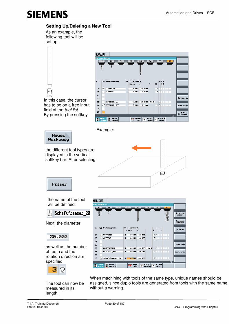
Setting Up/Deleting a New Tool
As an example, the following tool will be set up.
In this case, the cursor has to be on a free input field of the tool list. By pressing the softkey
the different tool types are displayed in the vertical softkey bar. After selecting
the name of the tool will be defined.
Example:
Next, the diameter
as well as the number of teeth and the rotation direction are specified
The tool can now be measured in its length.
When machining with tools of the same type, unique names should be assigned, since duplo tools are generated from tools with the same name, without a warning.

Automation and Drives – SCE
T I A Training Document Page 31 of 187 Status: 04/2008 CNC – Programming with ShopMill
To delete a tool from the tool list, select the location with the tool. By pressing the softkey
the following softkeys are diesplayed:
By pressing the softkey
the selected tool is deleted from the tool list.
Take note of the machine manufacturer’s data. In the case of some manufacturers, an active tool can not be deleted.

Automation and Drives – SCE
T I A Training Document Page 32 of 187 Status: 04/2008 CNC – Programming with ShopMill
7.6 A Tool with Several Edges
A tool with several edges is set up as described above. By pressing the softkey
the input screen form is displayed where several edges can be defined.
By pressing the softkey
an additional edge can be set up for the selected tool.

Automation and Drives – SCE
T I A Training Document Page 33 of 187 Status: 04/2008 CNC – Programming with ShopMill
7.7 Sorting the Tools
When calling the tool list and pressing the softkey
the four options for sorting the tools are displayed.
The sorting that is active is shown darkend.
For sorting according to
the tools are shown in the ascending mode according to their magazine location. When sorting accoding to
the tools are shown in the alphabetical order of the name.

Automation and Drives – SCE
T I A Training Document Page 34 of 187 Status: 04/2008 CNC – Programming with ShopMill
When sorting
the tools are sorted according to the tool type. When sorting
tool names that are defined by numbers are sorted in the ascending mode.

Automation and Drives – SCE
T I A Training Document Page 35 of 187 Status: 04/2008 CNC – Programming with ShopMill
8 Programming Example: Contour Programming
8.1 Example of Contour Programming
The contour calculator and subsequent machining are described, based on an example.
A ShopMill program is to be created for this workpiece. After setting up a program with the name “Mounting Plate“, the inputs are made in the program header.
4°
R20
A
A
R20
0
50
75
95
305
12
0
14
5
150
10
020
5

Automation and Drives – SCE
T I A Training Document Page 36 of 187 Status: 04/2008 CNC – Programming with ShopMill
8.2 Face Milling
The workpiece surface is milled in order to obtain a level, clean surface. This is done with face milling.
After accepting the program header, face milling is performed next. After entering the values in the input screen form,
face milling is accepted into the machining plan.

Automation and Drives – SCE
T I A Training Document Page 37 of 187 Status: 04/2008 CNC – Programming with ShopMill
8.3 Contour Calculator
With the contour calculator, even difficult contours can be programmed relatively easily.
Next, the milling contour is described.
After setting up a new contour,
Automation and Drives – SCE
T I A Training Document Page 38 of 187 Status: 04/2008 CNC – Programming with ShopMill
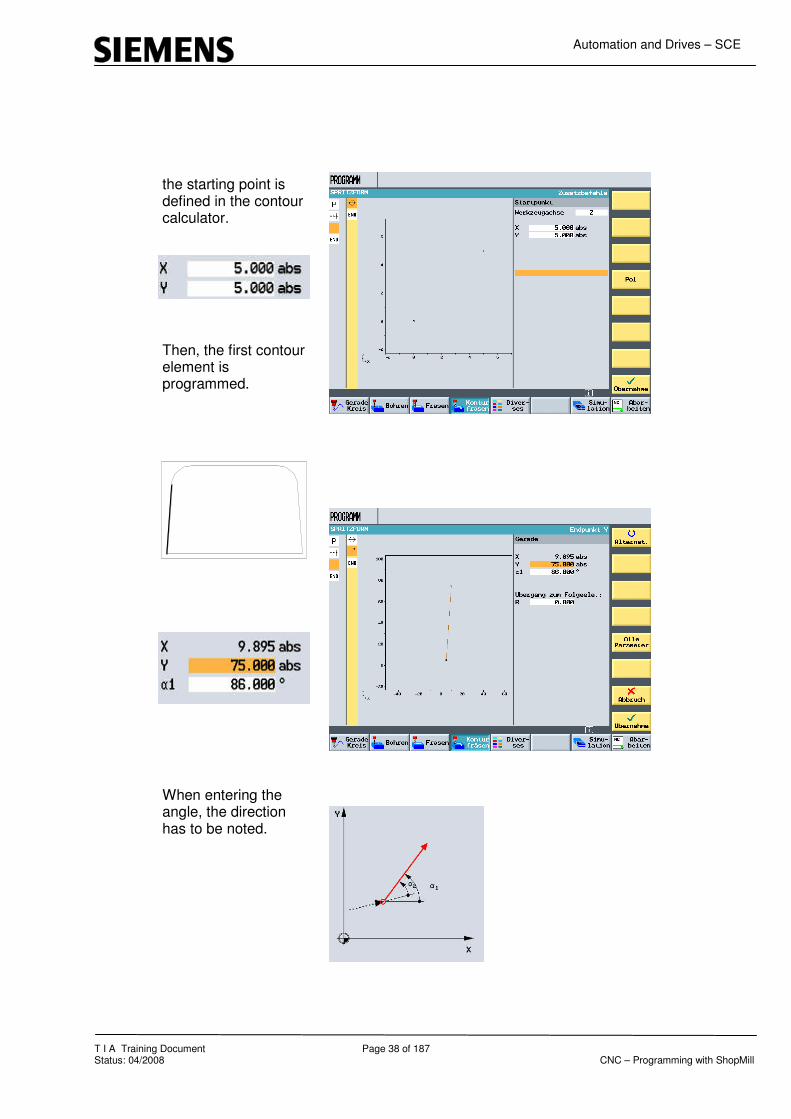
the starting point is defined in the contour calculator.
Then, the first contour element is programmed.
When entering the angle, the direction has to be noted.

Automation and Drives – SCE
T I A Training Document Page 39 of 187 Status: 04/2008 CNC – Programming with ShopMill
Next, the arc is programmed
After entering the values
a dialog selection is displayed. By pressing the softkey
the selected element is accepted into the contour calculator. The direction of the element selected in the dialog can be changed any time by pressing the softkey

Automation and Drives – SCE
T I A Training Document Page 40 of 187 Status: 04/2008 CNC – Programming with ShopMill
The next element is a straight line in X direction.
Then, an arc follows again.
For this element also, a dialog selection is made which is accepted into the contour calculator by pressing the softkey

Automation and Drives – SCE
T I A Training Document Page 41 of 187 Status: 04/2008 CNC – Programming with ShopMill
The next element is an oblique line whose end point is known.
With the last contour element, a straight line, the contour is closed.
By pressing the softkey Additional
and Close Contour
the contour is completely generated.

Automation and Drives – SCE
T I A Training Document Page 42 of 187 Status: 04/2008 CNC – Programming with ShopMill
8.4 Path Milling
After accepting the contour in the machining plan
a bracket opens next to the symbol for the contour element. Next, the machining process is described. Path milling is to be used for machining.
By pressing the softkey
In the area “Contour milling“, a corresponding input screen form is opened.

Automation and Drives – SCE
T I A Training Document Page 43 of 187 Status: 04/2008 CNC – Programming with ShopMill
8.5 Forward-Backward
We can also machine against the programmed contour (backward).
After entering the tool, the technology and selecting the radius correction
we can then specify the machining direction in reference to the contour.
The contour is processed in the direction the contour was programmed.
The contour is processed against the contour’s programmed direction. After entering the machining strategy,
the approach and the return strategy as well as the retraction mode are defined.

Automation and Drives – SCE
T I A Training Document Page 44 of 187 Status: 04/2008 CNC – Programming with ShopMill
Accepting the machining into the machining plan
closes the bracket. A machining was added to the contour.
The program is done.
Automation and Drives – SCE
T I A Training Document Page 45 of 187 Status: 04/2008 CNC – Programming with ShopMill
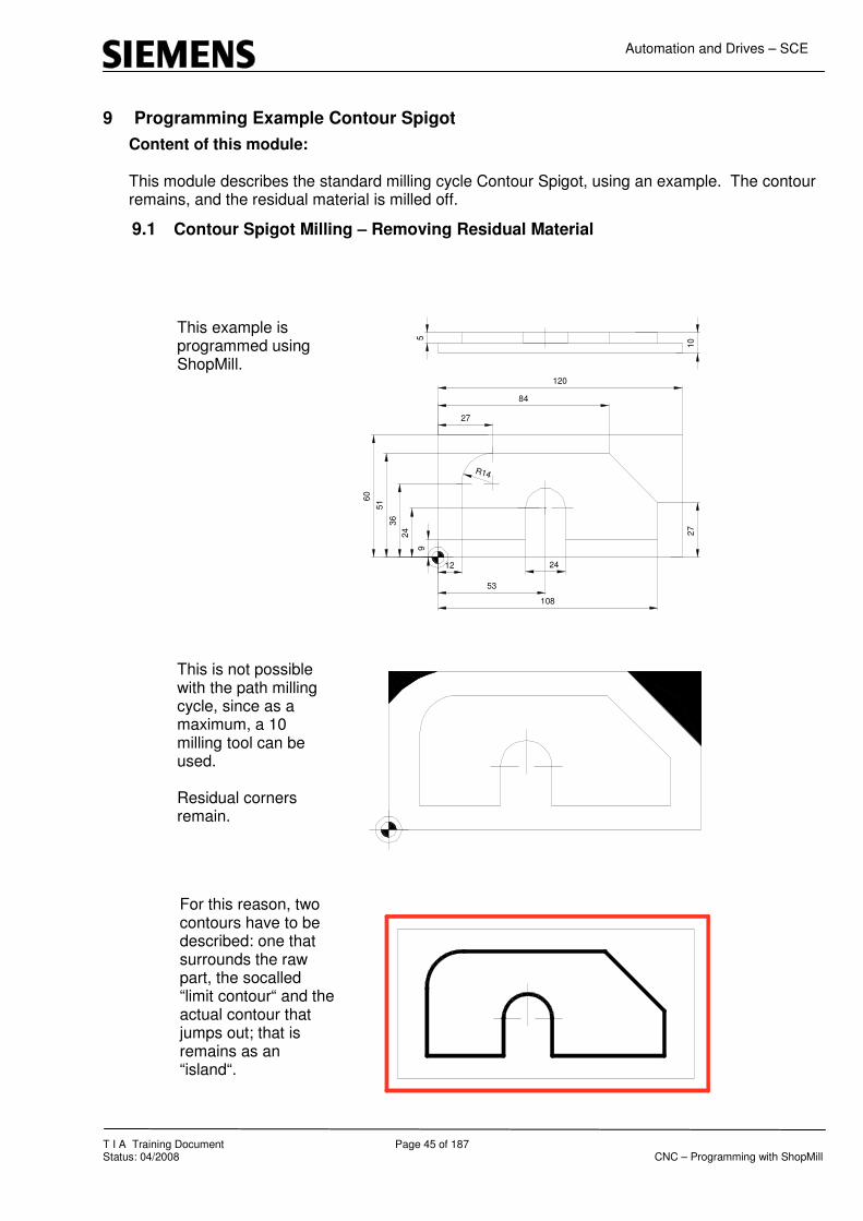
9 Programming Example Contour Spigot
9.1 Contour Spigot Milling – Removing Residual Material
Content of this module: This module describes the standard milling cycle Contour Spigot, using an example. The contour remains, and the residual material is milled off.
Beispiel
This example is programmed using ShopMill.
This is not possible with the path milling cycle, since as a maximum, a 10 milling tool can be used. Residual corners remain.
For this reason, two contours have to be described: one that surrounds the raw part, the socalled “limit contour“ and the actual contour that jumps out; that is remains as an “island“.
9
12
53
108
27
27
8424
36
516
0
105
R14
120
24
Automation and Drives – SCE
T I A Training Document Page 46 of 187 Status: 04/2008 CNC – Programming with ShopMill
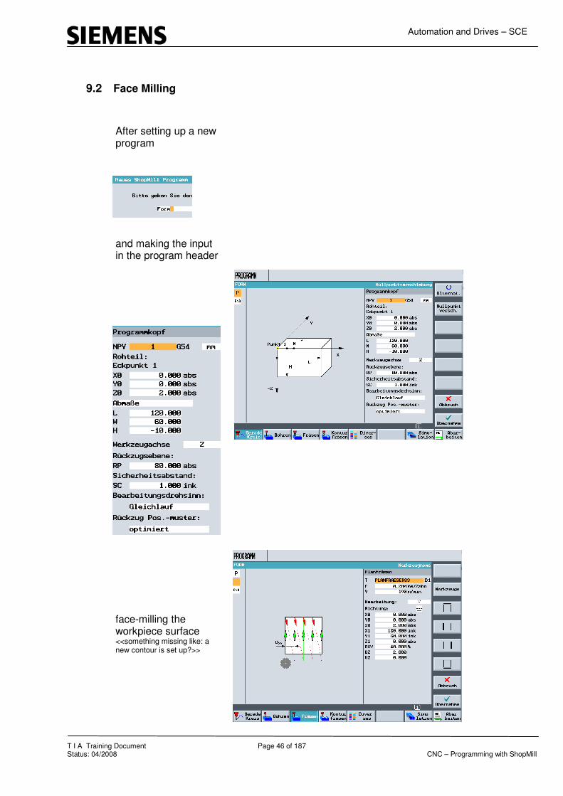
9.2 Face Milling
After setting up a new program
and making the input in the program header
face-milling the workpiece surface <<something missing like: a new contour is set up?>>

Automation and Drives – SCE
T I A Training Document Page 47 of 187 Status: 04/2008 CNC – Programming with ShopMill
After setting up a new program
and making the inputs in the program header
face-milling the workpiece surface,
a new contour is set up <<same page twice?>>.

Automation and Drives – SCE
T I A Training Document Page 48 of 187 Status: 04/2008 CNC – Programming with ShopMill
9.3 First Contour Limit-Contour
This contour, a little larger than the workpiece, will later describe the machining limit. The initial machining continues to be done with the facing tool.
In the case of spigot milling, the “limit contourr“ can be angular. When describing a contour pocket, the contour corners should have a radius. The corner radius should be at least as large as the radius of the largest tool.

Automation and Drives – SCE
T I A Training Document Page 49 of 187 Status: 04/2008 CNC – Programming with ShopMill
9.4 Second Contour: Actual Contour Spigots
Next, a second contour is programmed.
After accepting the contour in the machining plan, the cycle for contour spigot milling is opened by pressing the softkey

Automation and Drives – SCE
T I A Training Document Page 50 of 187 Status: 04/2008 CNC – Programming with ShopMill
By machining from the outside to the inside, tough and hard materials can also be machined in this cycle.
The strategy is that we always start outside of the workpiece when starting machining.
Then, the values are entered.

Automation and Drives – SCE
T I A Training Document Page 51 of 187 Status: 04/2008 CNC – Programming with ShopMill
9.5 Spigot – Residual Material
The values that were entered are accepted into the machining plan. Thus, the bracket with the two contour elements is closed.
Since based on the milling tool diameter of 30mm the workpiece can not be completely manufactured, another machining cycle follows; socalled “residual material processing“. Pressing the softkey

Automation and Drives – SCE
T I A Training Document Page 52 of 187 Status: 04/2008 CNC – Programming with ShopMill
opens the cycle for residual material machining. After selecting a smaller milling tool and inputting the values,
this cycle is accepted into the machining plan. This cycle is added to the bracket.
The program is done.

Automation and Drives – SCE
T I A Training Document Page 53 of 187 Status: 04/2008 CNC – Programming with ShopMill
10 Programming Example Standard Milling Cycles Machining with the standard milling cycles under ShopMill is described, using an example .
10.1 Programming Example for Milling Cycles (Rectangular Spigot, Circular Pocket)
This workpiece “Mounting Plate “ is to be generated using the milling cycles
After setting up a program named "Mounting Plate“
Ø50
75
100
10
25
100
the raw part for the simulation is entered, after entering the zero point.
After entering the additional values in the program header

Automation and Drives – SCE
T I A Training Document Page 54 of 187 Status: 04/2008 CNC – Programming with ShopMill
and accepting them into the machining plan, the next step consists of facing.
Pressing the softkeys
and
Automation and Drives – SCE
T I A Training Document Page 55 of 187 Status: 04/2008 CNC – Programming with ShopMill
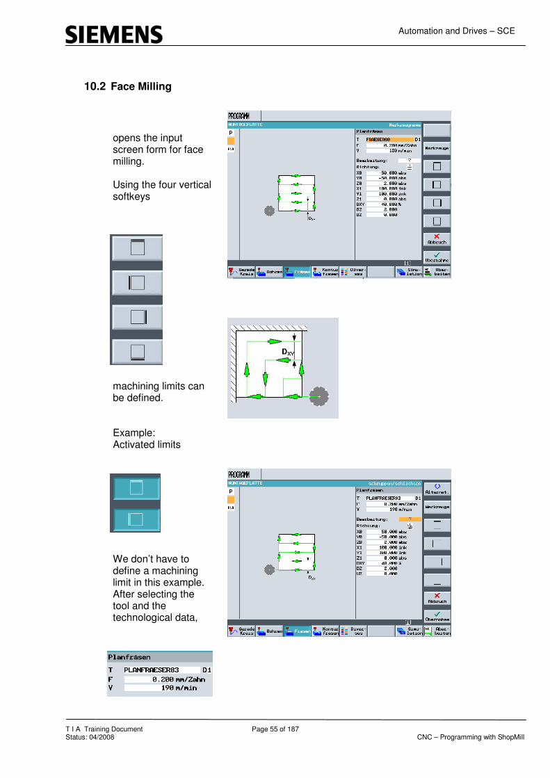
10.2 Face Milling
opens the input screen form for face milling. Using the four vertical softkeys
machining limits can be defined. Example: Activated limits
We don’t have to define a machining limit in this example. After selecting the tool and the technological data,

Automation and Drives – SCE
T I A Training Document Page 56 of 187 Status: 04/2008 CNC – Programming with ShopMill
next Rouging,
or Finishing
is selected. Then, we select the machining strategy.

Automation and Drives – SCE
T I A Training Document Page 57 of 187 Status: 04/2008 CNC – Programming with ShopMill
After entering the values, face milling is accepted into the machining plan
by pressing the softkey

Automation and Drives – SCE
T I A Training Document Page 58 of 187 Status: 04/2008 CNC – Programming with ShopMill
10.3 Rectangular Spigot
Next, the rectangular spigot is programmed.
Pressing the softkey
in the area Milling and selecting
opens the input field.

Automation and Drives – SCE
T I A Training Document Page 59 of 187 Status: 04/2008 CNC – Programming with ShopMill
After selecting the tool with the corresponding technology,
next the reference point of the reactangular spigot is defined.

Automation and Drives – SCE
T I A Training Document Page 60 of 187 Status: 04/2008 CNC – Programming with ShopMill
After selecting the position
the spigot and the machining strategy are described.
Finally, the raw part spigot is specified that is to be machined.
The spigot is programmed.
The material between the raw part spigot and the finished part spigot is machined in a lateral feed setting. If the feed setting is too large, the completed spigot should be programmed in several steps.

Automation and Drives – SCE
T I A Training Document Page 61 of 187 Status: 04/2008 CNC – Programming with ShopMill
10.4 Circular Pocket
Finally, the circular pocket is programmed.
By selecting the cycle “circular pocket“, the corresponding input field opens. After selecting the tool and entering the technology data
the circular pocket is programmed.
Immersion in the material can be centered
or helical. For helical“ immersion, a Z-motion is superimposed on the X-Y motion. The milling tool backs off permanently because of this.

Automation and Drives – SCE
T I A Training Document Page 62 of 187 Status: 04/2008 CNC – Programming with ShopMill
Accepting the cycle into the machining plan completes the program
and can be simulated.

Automation and Drives – SCE
T I A Training Document Page 63 of 187 Status: 04/2008 CNC – Programming with ShopMill
10.5 Processing (Basic Block)
By pressing the softkey
the program is loaded to the operating mode
and can be processed. Pressing the softkey
displays the program during processing in an additional window in G-code.
By activating the basic block, the next programmed travel movements are visible. This makes a possible early intervention in program execution simpler for the operator.

Automation and Drives – SCE
T I A Training Document Page 64 of 187 Status: 04/2008 CNC – Programming with ShopMill
11 Programming Example – Position Patterns for Drilling and Milling Cycles Below, the position patterns for drilling and milling cycles under ShopMill are explained, using an example.
11.1 Example: Drilling and Milling Positions
A rectangle and the circular pockets are added to the example for contour programming. The program “Injection Mold“ is selected in the area
Pressing the softkeys
and
opens a dialog window.

Automation and Drives – SCE
T I A Training Document Page 65 of 187 Status: 04/2008 CNC – Programming with ShopMill
Since the existing program is not to be overwritten, a 2 is appeded to the name of the program. By pressing the softkey
a new program named “InjectionMold2“ is stored in the selected directory.

Automation and Drives – SCE
T I A Training Document Page 66 of 187 Status: 04/2008 CNC – Programming with ShopMill
11.2 Rectangular Pocket
After opening the program, the corresponding cycle for machining the center pocket is called by pressing the softkey
and
.
A
A
60
40
30°
Ø30
R20
0
25
50
75
95
305 75
12
0
14
5
150
10
02
0
5
10
15
R6

Automation and Drives – SCE
T I A Training Document Page 67 of 187 Status: 04/2008 CNC – Programming with ShopMill
If necessary, any number of position patterns can be described one after the other.
After entering the corresponding values in the input screen form
and acceptance into the machining plan,
the rectangular pocket is programmed.

Automation and Drives – SCE
T I A Training Document Page 68 of 187 Status: 04/2008 CNC – Programming with ShopMill
11.3 Circular Pockets
Next, the circular pockets are programmed.
After opening the corresponding cycle
and <<something missing?>>, the tool with the corresponding technology is entered.

Automation and Drives – SCE
T I A Training Document Page 69 of 187 Status: 04/2008 CNC – Programming with ShopMill
11.4 Position Pattern
Now, not the Individual Position
as previously, but -since it is a question of several circular pockets of the same type- by pressing the softkey
the
is selected. Based on this selection,
it is no longer possible to describe positions in the input screen form of the cycle. Input of values in the screen form.

Automation and Drives – SCE
T I A Training Document Page 70 of 187 Status: 04/2008 CNC – Programming with ShopMill
11.5 Drilling and Positions
As an alternative, the circular pocket positions can also be entered with the position pattern “Frame“.
Through acceptance into the machining plan, an open bracket is displayed at the circular pocket.
Next, the positions of the circular pockets are programmed. Pressing the softkey
and
opens the corresponding input field.

Automation and Drives – SCE
T I A Training Document Page 71 of 187 Status: 04/2008 CNC – Programming with ShopMill
After entering the corresponding positions in the input screen form
and acceptance into the machining plan, the bracket is closed and the program is complete.

Automation and Drives – SCE
T I A Training Document Page 72 of 187 Status: 04/2008 CNC – Programming with ShopMill
12 Program Example – Centering, Drilling, Threading
In this module, centering, drilling and threading under ShopMill is described.
12.1 Exercises for Centering, Drilling, and Threading
As an example for centering, drilling and threading, this drawing is to be programmed. After setting up a new program,
defining the program header,
and programming the face milling cycle,
the next step consists of programming the centering.

Automation and Drives – SCE
T I A Training Document Page 73 of 187 Status: 04/2008 CNC – Programming with ShopMill
12.2 Centering the Frame and the Hole Circle
After opening the input screen form for the centerings (spot drilling), the values are entered in the input fields.
Since at none of the holes a chamfer is programmed, centering can be done for all holes.
The positions of the center circle

Automation and Drives – SCE
T I A Training Document Page 74 of 187 Status: 04/2008 CNC – Programming with ShopMill
as well as the outside frame are programmed.

Automation and Drives – SCE
T I A Training Document Page 75 of 187 Status: 04/2008 CNC – Programming with ShopMill
12.3 Drilling
After accepting the position patterns into the machining plan, the centerings for the holes are completely programmed.
Next, the holes for the center hole circle are programmed.

Automation and Drives – SCE
T I A Training Document Page 76 of 187 Status: 04/2008 CNC – Programming with ShopMill
12.4 Programming "Drilling the Hole Circle“ by Using Copy and Insert
After opening the input screen form for drilling and entering the values,
the input is acccepted into the machining plan. Since the drilling positions were already programmed, they are appended to the boring by pressing the softkeys
and
The center borings are completely generated.

Automation and Drives – SCE
T I A Training Document Page 77 of 187 Status: 04/2008 CNC – Programming with ShopMill
12.5 Borings Threads for Frames
Finally, the borings of the “frame“ are programmed.
After entering the values for the borings
and entering the values for the thread,

Automation and Drives – SCE
T I A Training Document Page 78 of 187 Status: 04/2008 CNC – Programming with ShopMill
the inputs are accepted into the machining plan.
Since the positions for the borings were already programmed also, they are again appended to the boring by pressing the softkeys
and
The program is completely generated.

Automation and Drives – SCE
T I A Training Document Page 79 of 187 Status: 04/2008 CNC – Programming with ShopMill
13 Programming Example – Programmable Transformations, Subprogram Technology
Content of the Module: This module describes how ShopMill transformations and subprograms are programmed, using an example.
Transformations
Subprograms
Mirroring/rotating transformations
Based on this example, the functions “Program Loop“ - “Shift“ are explained in greater detail..
Setting up the program
All non-dimensioned radii R=5

Automation and Drives – SCE
T I A Training Document Page 80 of 187 Status: 04/2008 CNC – Programming with ShopMill
13.1 Program Header
After entering the values in the program header
and entering the parameters for face milling,
next the corner contour is programmed.

Automation and Drives – SCE
T I A Training Document Page 81 of 187 Status: 04/2008 CNC – Programming with ShopMill
13.2 Contour Calculator Left Upper Corner
After opening the contour calculator and defining the starting point for the left upper corner,
the contour is programmed incrementally.

Automation and Drives – SCE
T I A Training Document Page 82 of 187 Status: 04/2008 CNC – Programming with ShopMill
13.3 Path Milling
After accepting the contour into the machining plan,
the cycle “Path Milling“ is opened.
After accepting the values into the machining plan, corner machining is programmed.

Automation and Drives – SCE
T I A Training Document Page 83 of 187 Status: 04/2008 CNC – Programming with ShopMill
13.4 Mirroring
We don’t want to program this corner three more times, but mirror it under ShopMill. After pressing the soft key
and
the possible transformations under ShopMill are shown.
Pressing the softkey Mirroring
opens the corresponding input screen form.

Automation and Drives – SCE
T I A Training Document Page 84 of 187 Status: 04/2008 CNC – Programming with ShopMill
The corners are mirrored “additively“; that is, always in reference to the reference point that was mirrored last. After activating the corresponding axis
and accepting it into the machining plan, all additional program steps are inserted behind the mirror image around the X-axis.

Automation and Drives – SCE
T I A Training Document Page 85 of 187 Status: 04/2008 CNC – Programming with ShopMill
After highlighting and copying the contour with the associated processing of Copy
the contour is inserted behind the mirror image by pressing the softkey
Copied program parts are inserted below the current position.

Automation and Drives – SCE
T I A Training Document Page 86 of 187 Status: 04/2008 CNC – Programming with ShopMill
The second corner has been programmed
With another additive mirroring -this time around theY-axis-
and subsequent additive mirroring around the X-axis,
and additionally inserting the contour including the processing below the mirrorings

Automation and Drives – SCE
T I A Training Document Page 87 of 187 Status: 04/2008 CNC – Programming with ShopMill
13.5 Longitudinal Grooves
the program for the 4 corner machinings is completed
After entering the last corner, mirroring is still active and has to be switched off with
Next, the longitudinal grooves on both sides are milled. After opening the cycle for longitudinal grooves and entering the corresponding values in the input screen form,

Automation and Drives – SCE
T I A Training Document Page 88 of 187 Status: 04/2008 CNC – Programming with ShopMill
the cycle is accepted into the machining plan.
After opening the input screen form for the position pattern, entering the corresponding values
and acceptance into the machining plan, the longitudinal grooves are completely programmed.

Automation and Drives – SCE
T I A Training Document Page 89 of 187 Status: 04/2008 CNC – Programming with ShopMill
13.6 Circumferential Groove
Next, the circumferential grooves are programmed. After opening the cycle for circumferential grooves and entering the corresponding values in the input screen form,
the cycle is accepted into the machining plan. The circumferential grooves are completely programmed.

Automation and Drives – SCE
T I A Training Document Page 90 of 187 Status: 04/2008 CNC – Programming with ShopMill
13.7 Contour Pockets with Contour Calculator
Next, the contour pockets are programmed. After opening the contour calculator, that pocket’s starting point is defined.
Then, half the arc is programmed.

Automation and Drives – SCE
T I A Training Document Page 91 of 187 Status: 04/2008 CNC – Programming with ShopMill
By pressing the softkey
additional input options are available. The angle of opening that was dimensioned in this way is entered in the extended input screen form.

Automation and Drives – SCE
T I A Training Document Page 92 of 187 Status: 04/2008 CNC – Programming with ShopMill
Then, the oblique line is programmed. After opening the input screen form and pressing the softkey
the length of the oblique line as well as the angle to the predecessor element is entered.
Next, the lower arc is programmed. After opening the input screen form and pressing the softkey
the arc is programmed again by means of the angle of opening.

Automation and Drives – SCE
T I A Training Document Page 93 of 187 Status: 04/2008 CNC – Programming with ShopMill
Now the oblique line is programmed again. After opening the input screen form and pressing the softkey
the length of the oblique line as well as the angle to the predecessor element is entered.
With the last element, the contour is closed.

Automation and Drives – SCE
T I A Training Document Page 94 of 187 Status: 04/2008 CNC – Programming with ShopMill
14 Rotation Contour Pockets
After accepting the contour into the machining plan and adding the processing “Contour pocket“, the first pocket is completely programmed.
By pressing the softkey
in the area “Diverses“, the contour pocket is rotated around the Z-axis. After entering the rotation

Automation and Drives – SCE
T I A Training Document Page 95 of 187 Status: 04/2008 CNC – Programming with ShopMill
and copying and inserting the contour with the processing below the rotation, the second contour pocket is complete.
The last contour pocket is generated in the same way.
Delete the rotation

Automation and Drives – SCE
T I A Training Document Page 96 of 187 Status: 04/2008 CNC – Programming with ShopMill
15 Making Holes with a Drill
As the last step, the holes are programmed.
After entering the values
and the positions

Automation and Drives – SCE
T I A Training Document Page 97 of 187 Status: 04/2008 CNC – Programming with ShopMill
the program is complete.

Automation and Drives – SCE
T I A Training Document Page 98 of 187 Status: 04/2008 CNC – Programming with ShopMill
16 Subprograms
In this program, subprograms are inserted as repetitions. To make the program more transparent, the contour pockets are moved to a subprogram. Nach Anlegen eines
by cutting out the contour pockets from the program "Pattern Plate“ and inserting them into the new program “Contour Pocket“. Then, the program is complete.
in the area “Diverses“
Now, the program has to be simulated once. This action calculates the program, and can be used as a subprogram .
By pressing the softkey

Automation and Drives – SCE
T I A Training Document Page 99 of 187 Status: 04/2008 CNC – Programming with ShopMill
the name of the subprogram is entered.
If the subprogram is located in the same path, no input is necessary under Path/Workpiece. The program name is entered without an extension such as *mpf* and accepted into the machining plan. The subprogram is complete.
Any main program can also be used as subprogram!

Automation and Drives – SCE
T I A Training Document Page 100 of 187 Status: 04/2008 CNC – Programming with ShopMill
17 Mould Making - Milling A mould making program is generated, using an example.
Prerequisites
Generating the Program
“High speed settings”
Calling the Subprogram
Processing the Program
Sequence

Automation and Drives – SCE
T I A Training Document Page 101 of 187 Status: 04/2008 CNC – Programming with ShopMill
17.1 Prerequisites
In addition to machining step programs, ShopMill can also process G-code mould making programs. The prerequisite for this are optimized drives. Program Structure In order to attain the optimum velocity control for the mould making programs, you should divide the mould making program into a central technology program and separate geometry programs, and not generate one complete program. Technology Program The technology program includes the basic settings such as zero point shift, tool calls, feed values, spindle speed, and control commands for velocity control. In addition, the technology program calls the geometry programs as subprograms. The technology program can be generated in the ShopMill’s G-code editor.. Geometry Program The geometry programs of the individual machining modes (roughing, prefinishing and finishing) exclusively contain the geometry values for the free form surface to be machined. The geometry programs are generated on an external CAM system in the form of G01 blocks. Depending on their application, the geometry programs have a size of 500KB up to 100MB. Programs of this size can no longer be processed directly in the NCK work memory, but have to be processed externally by means of EXTCALL. That means, the geometry programs have to be stored either on the hard drive of the PCU 50.3 (HMI Advanced) or on a Compact Flash Card at ShopMill on NCU (HMI Embedded). For both ShopMill variants you also have the option to store the geometry programs on a network drive.

Automation and Drives – SCE
T I A Training Document Page 102 of 187 Status: 04/2008 CNC – Programming with ShopMill
17.2 Program Structure Technology Program with Geometry Program
NCK Work Memory Hard Drive or Compact Flash Card
Technology Program Zero Point 1 Tool 1 Feed 1 Spindle Speed 1 High Speed Settings 1 EXTCALL Geometry Program 1 Zero Point 2 Tool 2 Feed 2 Spindle Speed 2 High Speed Settings 2 EXTCALL Geometry Program 2
Geometry Program 1 (Roughing) X Y Z X Y z ...
Geometry Program 2 (Prefinishing) X Y Z X Y Z
...
Complete Program Complete programs include the basic settings such as the zero point shift, tool function <<T word>> etc. as well as the geometriy values of the free form surface to be machined. However, programming the optimized velocity control for a complete program is very complicated. Complete programs are also generated on enternal CAM systems. Because of their size, the complete programs are located on the hard drive of the PCU 50.3 (HMI Advanced) or on the CompactFlash Card at ShopMill on the NCU (HMI Embedded). Here also you have the option to store the complete programs on a network drive.

Automation and Drives – SCE
T I A Training Document Page 103 of 187 Status: 04/2008 CNC – Programming with ShopMill
17.3 Program Structure Complete Program
Hard drive or Compact Flash Card
Complete Pregram Zero point Tool Feed Spindle speed High Speed Settings X Y Z X Y Z Feed X Y Z X Y Z ……...
Processing from the hard drive

Automation and Drives – SCE
T I A Training Document Page 104 of 187 Status: 04/2008 CNC – Programming with ShopMill
Data Transmission A mould making program can be copied directly to the controller from a network drive or a USB drive. • ShopMill on NCU (HMI Embedded) • The programs are copied to the user memory of the CompactFlash card. • PCU 50.3 (HMI Advanced) The programs are copied to the hard disk drive. Measuring the Tool When generating the geometry program, the CAM system takes the tool geometry into account. The calculated tool path refers either to the tool tip or the tool center point. That means, when you specify the length of your tools, you have to use the same reference point (tool tip or tool center point) as the CAM system. If you are using a ShopMill function for measuring your tools, the tool length refers to the tool tip. If, on the other hand, in the CAM system the tool center point was taken into account when calculating the tool path, you have to deduct in the tool list the radius of the tool from the length of the tool. To process mould making programs, the entry of the tool diameter in the too list is not relevant. However, to have a better overview, you should enter the tool diameter in the tool list nevertheless.

Automation and Drives – SCE
T I A Training Document Page 105 of 187 Status: 04/2008 CNC – Programming with ShopMill
17.4 Creating the Program
Setting Up the Program For the technology program, set up a new G-code program in the program manager and then edit it there. Editor. A machining step program is not suitable as a technology program. Create the geometry program or the complete program with an external CAM system. If afterwards you would like to add comments, for example, to the geometry program, or change the tool name in the complete program, you can use also the ShopMill G-code editor for this.
After entering a program name,
Use the arrow keys to open a directory.

Automation and Drives – SCE
T I A Training Document Page 106 of 187 Status: 04/2008 CNC – Programming with ShopMill
Programming the Tool If you program a tool in the technology program, you have to take note of the following: The geometry of the programmed tool has to agree with the tool geometry that the CAM system took into account when the geometry program was generated.
First, the tool, the spindle speed and the spindle direction are programmed. In addition, the following is programmed: feed, switching on the coolant, and the zero point shift with the starting point.
the G-code Editor under ShopMill is opened.

Automation and Drives – SCE
T I A Training Document Page 107 of 187 Status: 04/2008 CNC – Programming with ShopMill
17.5 High Speed Settings
Programming the Cycle "High Speed Settings"
When machining free form surfaces, great demands are made on the speed as well as the accuracy and surface quality. You can attain the optimum velocity rate in dependence on the machining mode (roughing, pre-finishing, finishing) very simply by using the cycle "High Speed Settings". You can call the cycle by means of the cycle support in the G-code editor. As a rule, the output tolerance of the post processor of the CAM system is entered in the parameter "Tolerance". Program the cycle in the technology program prior to calling the geometry program.
After pressing the softkeys

Automation and Drives – SCE
T I A Training Document Page 108 of 187 Status: 04/2008 CNC – Programming with ShopMill
the following input screen form opens, where we can select among the machining modes
Tolerance The required tolerance can be entered in the input screen form in the cycle for the program generated from the CAM system.
High speed settings

Automation and Drives – SCE
T I A Training Document Page 109 of 187 Status: 04/2008 CNC – Programming with ShopMill
If the compressor is active, it can be parameterized by means of the input screen form.
By pressing the softkey
we can select between
By pressing the softkey
we can select among

Automation and Drives – SCE
T I A Training Document Page 110 of 187 Status: 04/2008 CNC – Programming with ShopMill
Pressing the softkey
closes the input screen form. “CYCLE832” was accepted into the program.

Automation and Drives – SCE
T I A Training Document Page 111 of 187 Status: 04/2008 CNC – Programming with ShopMill
17.6 Calling the Subprogram
Call the geometry program as subprogram from the technology program. Since the geometry programs are not stored in the NC work memory but on the hard disk drive of the PCU 50.3, or on the Compact Flash Card of theTCU, or on a network, the subprogram has to be called with the G-code command "EXTCALL". PCU 50.3 The technology program and the geometry programs are located in the same directory on the hard disk drive. EXTCALL "Geometry program" Example: EXTCALL "SCHRUPPEN" <<ROUGHING>> NCU HMI Embedded Depending on the storage location of the geometry program on the Compact Flash Card, the programming syntax differs somewhat. • The geometry program is located directly on the Compact Flash Card EXTCALL ("C:\Geometrieprogramm.mpf") Example: EXTCALL ("C:\Schruppen.mpf") • The geometry program is located in a directory on the Compact Flash Card EXTCALL ("C:\Verzeichnis\Geometrieprogramm.mpf") Example: EXTCALL ("C:\Mold\Schruppen.mpf") Network drive If the geometry program is located on a network drive connected by means of the Ethernet, the programming syntax is as follows. EXTCALL ("Pfad\Geometrieprogramm.mpf") Example: EXTCALL ("H:\Mold\Schruppen.mpf")
Here, a program is called that is stored on the CFCard as mpf– program.

Automation and Drives – SCE
T I A Training Document Page 112 of 187 Status: 04/2008 CNC – Programming with ShopMill
17.7 Processing the Program
Select the technology program that is located in the NCK work memory like a standard G-code program for processing. The geometry program is then selected automatically with the command "EXTCALL". A complete program that is located either on the hard disk drive of the PCU 50.3 (HMI Advanced), or on the Compact Flash Card at ShopMill on NCU (HMI Embedded), or on a USB /network drive, is selected with the softkey "Execute hard drive" in the program manager.
Prior to executing the program, the program is simulated graphically by pressing the softkey

Automation and Drives – SCE
T I A Training Document Page 113 of 187 Status: 04/2008 CNC – Programming with ShopMill
Pressing the softkey
and
the program is selected in the operating area “Auto”.
Single Block
The program can be executed in the single block.
With “Cycle Start” the program can be executed step by step.
After positioning, the program can be executed without a single block.

Automation and Drives – SCE
T I A Training Document Page 114 of 187 Status: 04/2008 CNC – Programming with ShopMill
17.8 Starting Processing at a Certain Program Location
Executing the Program
Starting Processing at a Certain Program Location In order to start in a geometry program the execution of a certain program segment, enter the destination in the search pointer. Layer 1 (technology program): Program line with the call of the desired geometry program Layer 2 (geometry program): Program line for starting processing. If the geometry program is located on the Compact Flash Card, you not only have to specify in Layer 2 in the input field "Program" the program name, but also the path. Select the accelerated calculation variant "External – without calculation". The block search in the technology program is performed with calculation. In that case, all EXTCALL commands before the desired geometry program are skipped. The block search in the desired geometry program is performed without calculation. However, this calculation variant presupposes that all machine functions such as tool function, spindle speed etc. are located in the technology program. The geometry program must only contain geometry values for the free mold surface.
The line for starting the program can be selected with the arrow keys.
After pressing the two additional softkeys
Automation and Drives – SCE
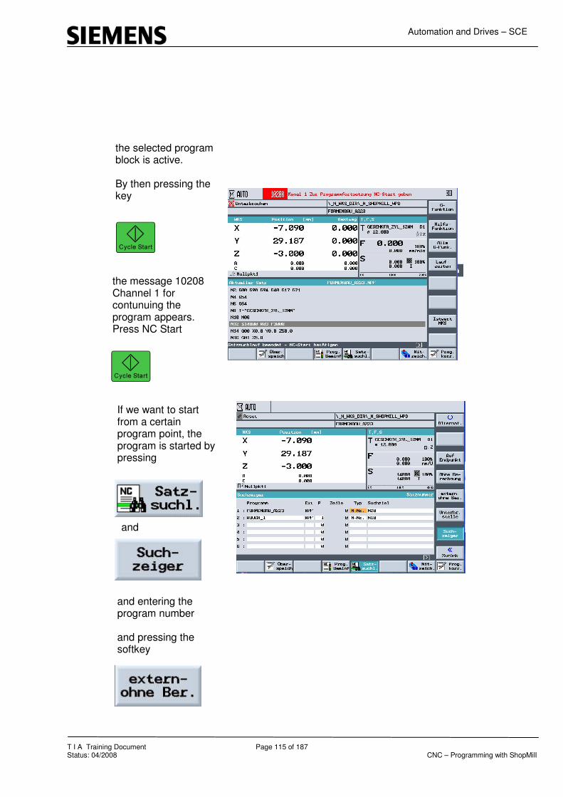
T I A Training Document Page 115 of 187 Status: 04/2008 CNC – Programming with ShopMill
the selected program block is active. By then pressing the key
the message 10208 Channel 1 for contunuing the program appears. Press NC Start
,
If we want to start from a certain program point, the program is started by pressing
and entering the program number and pressing the softkey
and

Automation and Drives – SCE
T I A Training Document Page 116 of 187 Status: 04/2008 CNC – Programming with ShopMill
Sample Program
In the program area “NC”, a mould making program is opened.
The corresponding technology data is located on the “CF Card“. With a mouse click, it was loaded to the “CF Card“ with a USB stick.

Automation and Drives – SCE
T I A Training Document Page 117 of 187 Status: 04/2008 CNC – Programming with ShopMill
17.9 Simulation of a Volume Model

Automation and Drives – SCE
T I A Training Document Page 118 of 187 Status: 04/2008 CNC – Programming with ShopMill
18 Information about Mould Making
Information about mould making is provided on the
Internet under
www.automation.siemens.com/doconweb/

Automation and Drives – SCE
T I A Training Document Page 119 of 187 Status: 04/2008 CNC – Programming with ShopMill
19 Fundamentals of CNC Machines
The difference between a manual and a CNC machine consists of the logic operation of numerical values. This module about the basics of CNC technology is to aid you regarding the CNC myth.
Reference position Z
Reference position X
Zero Offset
Tool Offset
Zero Offset
Reference Point Z
Reference Point X
Zero Point
Zero Point
Tool Zero
Point

Automation and Drives – SCE
T I A Training Document Page 120 of 187 Status: 04/2008 CNC – Programming with ShopMill
20 Manual Operating Area - Milling In this module, the individual function areas in the manual operating area are presented and if necessary, explained by using an example.
Set Zero Point Shift
Zero Point Workpiece
Operating Area TSM
Swiveling
Measuring the Tool
Face Milling Cycle
Positioning

Automation and Drives – SCE
T I A Training Document Page 121 of 187 Status: 04/2008 CNC – Programming with ShopMill
20.1 Operating Area TSM
Tool Spindle Speed Machine Functions
After starting ShopMill, the operating area
is active.
By pressing the softkey
the input window for operating the machine manually is displayed.

Automation and Drives – SCE
T I A Training Document Page 122 of 187 Status: 04/2008 CNC – Programming with ShopMill
In the first input screen form, the tool is defined.
The spindle speed can be entered only in
In the additinal input fields, M-functions and zero point shifts can be input.
We can select between the measurement units
The tool axis
can also be selected.
.

Automation and Drives – SCE
T I A Training Document Page 123 of 187 Status: 04/2008 CNC – Programming with ShopMill
Example:
After calling the tool with the corresponding technology
the tool with the input technology data is activated by pressing the NC start key

Automation and Drives – SCE
T I A Training Document Page 124 of 187 Status: 04/2008 CNC – Programming with ShopMill
20.2 Operating Area Set NPV
The operating area "Set NPV“ is needed for synchronizing the axes and the workpiece.
Example: The edge of the workpiece is scratched.with a milling tool.
By pressing the softkey
the value for the current axis is colored.
Using the following softkeys, each axis can be “zeroed“..
Also, using the machine keyboard, any value can be entered in the field that is currently selected, or with
the value of the axis can be set to zero.

Automation and Drives – SCE
T I A Training Document Page 125 of 187 Status: 04/2008 CNC – Programming with ShopMill
20.3 Operating Area Zero Point Workpiece
The value is taken into account in the active zero point shift and entered in the zero point table
In this operating mode, the value for the workpiece measurement can be written directly into the desired zero point shift. ShopMill Version 6.4 offers many options for this. Pressing the softkey

Automation and Drives – SCE
T I A Training Document Page 126 of 187 Status: 04/2008 CNC – Programming with ShopMill
offers five options for determining the zero point. Edge Corner Drilling rectangular pocket Spigot Rectangle Aligning the plane
The described cycles can be utilized by using a manual touch probe or an automatic touch probe.
By pressing the softkey
the options for “Edge measurement“ under ShopMill are displayed.

Automation and Drives – SCE
T I A Training Document Page 127 of 187 Status: 04/2008 CNC – Programming with ShopMill
Pressing the softkey
opens the input screen form. After selecting the zero point shift
and the axis
measurements can be made.
After the measurement is performed into <<?>> a non-active zero point, a query is displayed whether the zero point is to be activated.
By pressing the softkey
the input is accepted and the zero point is activated.

Automation and Drives – SCE
T I A Training Document Page 128 of 187 Status: 04/2008 CNC – Programming with ShopMill
20.4 Measuring the Tool Length
By pressing the softky
in the operating area
and pressing the softkey
the tool is measured by starting the workpiece in the length - Z – direction.

Automation and Drives – SCE
T I A Training Document Page 129 of 187 Status: 04/2008 CNC – Programming with ShopMill
After selecting the tool
selecting the reference point whether
or
a tolerance can be entered after “scratching“ the surface of the workpiece.
By pressing the softkey
the measured tool length is activated and accepted into the tool list.

Automation and Drives – SCE
T I A Training Document Page 130 of 187 Status: 04/2008 CNC – Programming with ShopMill
20.5 Measuring the Tool Radius
Next, the tool’s diameter is ascertained.
By pressing the softkey
in the area “Measure tool“, the corresponding input screen form opens. After selecting the tool
a tolerance can be entered in reference to the tool edge in X and in Y.
After approaching the workpiece edge with the tool, the measured diameter is activated by pressing the softkey
and accepted into the tool list.

Automation and Drives – SCE
T I A Training Document Page 131 of 187 Status: 04/2008 CNC – Programming with ShopMill
20.6 Swiveling
By pressing the softkey
in the operating area Manual
the area for manual swiveling under ShopMill opens.
Manual swiveling under ShopMill is not part of the training document.

Automation and Drives – SCE
T I A Training Document Page 132 of 187 Status: 04/2008 CNC – Programming with ShopMill
20.7 Manual Positioning
By pressing the softkey
in the operating area
the target position is entered in the input fields.
The travel motion can be entered in feed or
rapid feed
.
There is no collision monitoring when the target position is approached.

Automation and Drives – SCE
T I A Training Document Page 133 of 187 Status: 04/2008 CNC – Programming with ShopMill
20.8 Manual Face Milling
Pressing the softkey
in the operating area
opens the input field for the face milling cycle.
This face milling cycle is described in greater detail in the chapter “Programming Example Standard Milling Cycle“.
The face milling in the operating area Manual described above offers the only possibility to utilize a cycle under ShopMill 6.4 without having to create a program.

Automation and Drives – SCE
T I A Training Document Page 134 of 187 Status: 04/2008 CNC – Programming with ShopMill
21 Measuring the Workpieces in the Setup Mode JOG - Milling
This module describes how to work in the setup mode with measuring cycles under ShopMill, using an example.
Measuring the Edge
Measuring the Corner
Requirement
Measuring Pocket and Hole
Measuring Spigots
Aligning the Plane

Automation and Drives – SCE
T I A Training Document Page 135 of 187 Status: 04/2008 CNC – Programming with ShopMill
21.1 Measuring Manually – Measuring Automatically
Measuring Manually When measuring the zero point manually, you have to move your tool manually to the workpiece. You can use edge probes, touch probes, or clock gauges whose radius and length is known. As an alternative, you can also use any tool with a known radius and a known length. However, the tools used for measuring must not be of the type 3DProbe. Measuring Automatically For automatic measuring, use exclusively electronic touch probes of the type 3D probes, or mono probes. The electronic touch probes have to be calibrated beforehand. For automatic measuring, preposition the probe first manually. After starting with the key “Cycle-Start“, the probe is moved automatically with measuring feed to the workpiece and back again to the start position with rapid feed. To be able to measure the workpiece zero point automatically, the machine manufacturer has to set up the measuring cycles beforehand.
To obtain the desired measuring results, as a rule the sequence of the measuring points has to be noted that is shown in the help displays. Measuring points can be undone and then measured repeatedly. This is done by operating the softkey that is shown as being active (measuring value). For manual measuring, the reset can be made in any sequence; however, for automatic measuring only in the reverse measuring sequence. Measuring Only If you want to "only measure" the workpiece zero point, the measured values are displayed without the coordinate system being changed.
Please take note of the machine manufacturer’s data.

Automation and Drives – SCE
T I A Training Document Page 136 of 187 Status: 04/2008 CNC – Programming with ShopMill
21.2 Measuring the Edge
When measuring an edge, you have the following options: • Setting the edge The workpiece is located on the work table parallel to the coordinate system. Measure one reference point in one of the axes (X, Y, Z). • Setting up the edge The workpiece is located randomly on the work table; that is, not parallel to the coordinate system. By measuring two points at the edge of the workpiece, you determine the angle to the coordinate system. . Distance 2 edges The workpiece is loacted on the work table parallel to the coordinate system. Measure the distance L of two parallel workpiece edges in one of the axis (X, Y or Z) and determine its center. Below, an example is used to describe how to measure the edge of a workpiece.

Automation and Drives – SCE
T I A Training Document Page 137 of 187 Status: 04/2008 CNC – Programming with ShopMill
or or
For “Measure Edge,” press the softkey below
and
and
With the
selection of
By pressing the softkey

Automation and Drives – SCE
T I A Training Document Page 138 of 187 Status: 04/2008 CNC – Programming with ShopMill
Pressing the arrow ey
and
To change the axes, press
or
For manual measuring, approach the workpiece with the probe.
For automatic measuring, approach the workpiece closely and press ”CYCLE START”.
The position of the workpiece edge is calculated and displayed.

Automation and Drives – SCE
T I A Training Document Page 139 of 187 Status: 04/2008 CNC – Programming with ShopMill
21.3 Measuring the Corner
You have the option of measuring workpieces with an angle of 90° as well as with any angles. • Measuring a right-angled corner The workpiece has a 90° corner and is located randomly on the work table. By measuring 3 points, the corner point in the working plane (X/Y plane) is ascertained and the angle α between the reference edge at the workpiece (line through P1 and P2) and the reference axis (always the 1st axis of the work plane). • Measuring any corner The workpiece has any type of corner (not a rectangular one) and is located randomly on the work table. By measuring 4 points, we determine the following: the corner point in the work plane (X/Y plane), angle α between the reference edge at the workpiece (line through P1 and P2) and the reference axis (always the 1st axis of the work plane), and angle β of the corner. Below, measuring a workpiece under one angle is described.

Automation and Drives – SCE
T I A Training Document Page 140 of 187 Status: 04/2008 CNC – Programming with ShopMill
or
To measure the edge, press
and
and
Press
and go to
Press

Automation and Drives – SCE
T I A Training Document Page 141 of 187 Status: 04/2008 CNC – Programming with ShopMill
To select “outside corner” “inside corner” press
and
To select the corner, press
Measuring a Corner

Automation and Drives – SCE
T I A Training Document Page 142 of 187 Status: 04/2008 CNC – Programming with ShopMill
To measure “P1” approach it and press P1 stored
Repeat this for “P2” and “P3”
For automatic measurements, move in front of the measuring point and press “CYCLE START”
The corner point and the angles α or β are calculated and displayed.

Automation and Drives – SCE
T I A Training Document Page 143 of 187 Status: 04/2008 CNC – Programming with ShopMill
21.4 Measuring the Pocket and Hole
You have the option to measure rectangular pockets as well as several holes, and then align the workpiece. • Measuring the reactangular pocket The rectangular pocket has to be set up at a right angle to the coordinate system. By measuring 4 points within the pocket, the length, width and center of the pocket is ascertained. • Measuring 1 hole The workpiece is located randomly on the work table and has 1 hole. By means of 4 measuring points, we determine the diameter and the center of the hole. • Measuring 2 holes The workpiece is located randomly on the work table and has 2 holes. In both holes, 4 points respectively are measured automatically and from that the center of the holes is calculated. From the connection line between the two center points and the reference axis, angle α is calculated as well as the new zero point is determined that corresponds to the center of the 1st hole. • Measuring 3 holes The workpiece is located randomly on the work table and has 3 holes. In the 3 holes, 4 points respectively are measured automatically and from that, the center of the holes is calculated. A circle is placed through the three center points. From that, the center of the circle and the diameter of the circle are ascertained. When selecting a phase angle correction, the basic rotation α can be determined in addition. • Measuring 4 holes The workpiece is located randomly on the work table and has 4 holes. In the 4 holes, 4 points respectively are measured automatically and from that the center of the holes is calculated. Two centers respectively of a hole are connected diagonally. From that, the intersection of the two lines is determined. When selecting a phase angle correction, the basic rotation α can be determined in addition. 2, 3 and 4 holes can only be measured automatically. Below, “Measuring a hole“ s described.
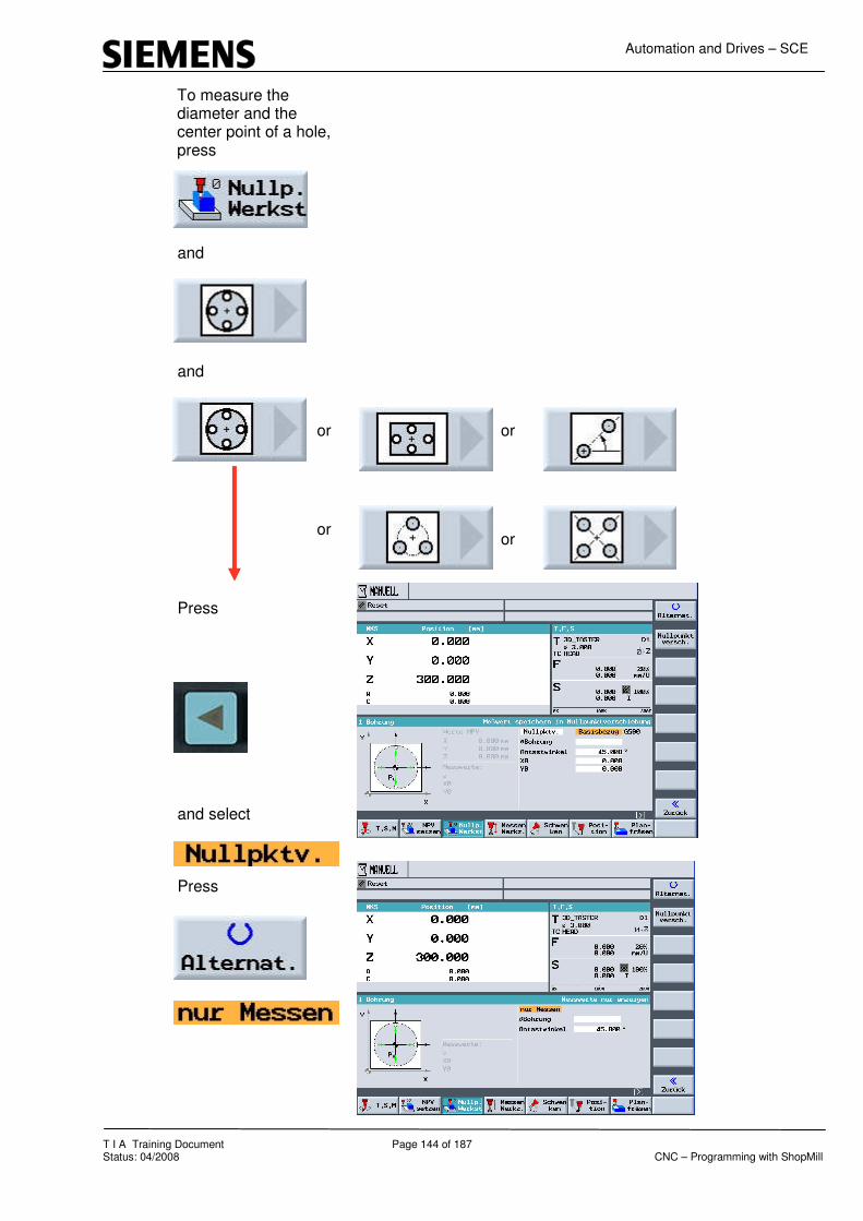
Automation and Drives – SCE
T I A Training Document Page 144 of 187 Status: 04/2008 CNC – Programming with ShopMill
To measure the diameter and the center point of a hole, press
and
and
Press
and select
Press
or or
or or

Automation and Drives – SCE
T I A Training Document Page 145 of 187 Status: 04/2008 CNC – Programming with ShopMill
Go to “Hole diameter”
Select the “contact angle”.
Select the first point that is described in the menu as the first, and approach it.
For automatic measurement, move into the hole and press “CYCLE START”.
The diameter and the center point of the hole are calculated and displayed.

Automation and Drives – SCE
T I A Training Document Page 146 of 187 Status: 04/2008 CNC – Programming with ShopMill
21.5 Measuring Spigots
You have the option to measure and align rectangular spigots, as well as one and several circular spigots: • Measuring the rectangular spigot The rectangular spigot is to be aligned right-angled to the coordinate system. By measuring 4 points at the spigot, we ascertain the length, width and the center point of the spigot. • Measuring 1 circular spigot The workpiece is located randomly on the work table and has 1 spigot. With 4 measuring points, we determine the diameter and the center point of the spigot. • Measuring 2 circular spigots The workpiece is located randomly on the work table and has 2 spigots. At the two spigots, 4 points respectively are measured automatically, and from that the center points of the spigots are calculated. From the connection line between the two center points and the reference axis, angle α is calculated and the new zero point is determined that corresponds to the center point of the first spigot. • Measuring 3 circular spigots The workpiece is located randomly on the work table and has 3 spigots. At the three spigots, 4 points respectively are measured automatically and from that, the center points of the spigots are calculated. A circle is placed through the three center points, and the center point of the circle and the diameter of the circle are ascertained. When selecting a phase angle correction, the basic rotation α can be determined in addition. • Measuring 4 circular spigots The workpiece is located randomly on the work table and has 4 spigots. At the four spigots, 4 points respectively are measured automatically and from that, the center points of the spigots are calculated. Two center points of the spigots respectively are connected diagonally, and then the intersection of both lines is determined. When selecting a phase angle correction, the basic rotaton α can be determined in addition. 2, 3 and 4 circular spigots can only be measured automatically. Below, measuring a spigot is described.

Automation and Drives – SCE
T I A Training Document Page 147 of 187 Status: 04/2008 CNC – Programming with ShopMill
To measure the diameter or the center of a spigot, press
and
and
With the
go to the
and press
or or
or or

Automation and Drives – SCE
T I A Training Document Page 148 of 187 Status: 04/2008 CNC – Programming with ShopMill
With the cursor, go to Diameter Spigot and press
Go to the value “DZ” and press
When measuring automatically, approach the workpiece and press “CYCLE START”.
Go the the contact angle and press
Select the first point that is described first in the menu, and approach it.

Automation and Drives – SCE
T I A Training Document Page 149 of 187 Status: 04/2008 CNC – Programming with ShopMill
The diameter and the center point of the spigot are calculated and displayed.

Automation and Drives – SCE
T I A Training Document Page 150 of 187 Status: 04/2008 CNC – Programming with ShopMill
21.6 Aligning the Plane
You can measure a spacially oblique plane of a workpiece, and ascertain the rotations α and β. With a subsequent coordinate rotation, the vertical alignment of the tool axis to the workpiece plane is possible. To determine the position of the plane in space, we measure in the tool axis at three different points. To align the tool axis vertically requires a tilting table or an inclinable head. For the plane to be measured, the surface has to be even. Below, measuring the oblique plane is described.

Automation and Drives – SCE
T I A Training Document Page 151 of 187 Status: 04/2008 CNC – Programming with ShopMill
To align and measure an oblique plane, press
and
. Press
. Go to
and press
Aligning the Plane

Automation and Drives – SCE
T I A Training Document Page 152 of 187 Status: 04/2008 CNC – Programming with ShopMill
For automatic measuring, approach the tool and press
Approach the first measuring point that is shown in the cycle, and save it.
Then, approach the other points.
Angles α and β are calculated and displayed.

Automation and Drives – SCE
T I A Training Document Page 153 of 187 Status: 04/2008 CNC – Programming with ShopMill
22 DIN/G-Code – Programming under ShopMill
In this module, programming in DIN under ShopMill is explained, using an example.
Under ShopMill, we can program in the socalled ISO G-code according to DIN 66025, and also with the cycles of the 840D. When setting up a new program, the DIN editor under ShopMill is opened by pressing the softkey The proram example is generated by using the standard cycles. The follwing G-functions are used for generating the program.
G17– Machining plane XY plane G41– Tool radius compensation (left) G54– Active zero point shift G90– Absolute measurement programming G94– Feed in mm/min

Automation and Drives – SCE
T I A Training Document Page 154 of 187 Status: 04/2008 CNC – Programming with ShopMill
The workpiece below is to be programmed in G-code with cycle support.
In contrast to the standard cycles, the ShopMill cycles include the approach and retract strategy to the contour.

Automation and Drives – SCE
T I A Training Document Page 155 of 187 Status: 04/2008 CNC – Programming with ShopMill
After entering the basic commands, calling the tool and after the approach position prior to processing, the corresponding cycle is opened by pressing the softkey and After entering the values and pressing the softkey the cycle is closed and accepted. Next, the contour is described.

Automation and Drives – SCE
T I A Training Document Page 156 of 187 Status: 04/2008 CNC – Programming with ShopMill
22.1 Generating the Contour with the Contour Calculator
opens the standard contour calculator. After entering the values and pressing the the contour element is accepted as for ShopMill.
Pressing

Automation and Drives – SCE
T I A Training Document Page 157 of 187 Status: 04/2008 CNC – Programming with ShopMill
Element 1 To accept, press Element2 To accept, press Element 3 To accept, press Element 4 To accept, press

Automation and Drives – SCE
T I A Training Document Page 158 of 187 Status: 04/2008 CNC – Programming with ShopMill
Element 5 To accept, press Element 6 To accept, press To accept the contour, press The contour is shown as G-code.

Automation and Drives – SCE
T I A Training Document Page 159 of 187 Status: 04/2008 CNC – Programming with ShopMill
With the second tool, the grooves are made. Go to the end of the program and set up a new tool with the technology data. Then, the start position is defined.

Automation and Drives – SCE
T I A Training Document Page 160 of 187 Status: 04/2008 CNC – Programming with ShopMill
Pressing opens the tool list of ShopMill. After selecting the tool and pressing the softkey “into the program”, the tool is included in the program. By pressing the softkey the familiar simulation can also be started for a DIN program. You have the option to change the view using different softkeys.

Automation and Drives – SCE
T I A Training Document Page 161 of 187 Status: 04/2008 CNC – Programming with ShopMill
23 Multiple Clamping
The function "Multiple Clamping" optimizes the tool changes by means of several workpiece setups. This shortens the idle time since first, all machining of a tool is executed on all clampings prior to the next tool change being activated. In addition to two-dimensional clamping, you can use the function "Multiple clamping" also for rotating clamping bridges. To this end, the machine has to have an additional rotary axis (for example, an A axis) or a dividing unit. Please note the manufacturer’s data regarding this. Not only identical, but also differing workpieces can be processed with this function. The function "Multiple Clamping for Different Programs" is a software option. ShopMill generates automatically a single program from several programs. The tool sequence within a program is retained. Cycles and subprograms are not separated <<?>> Position patterns are processed as a unit <<?>>. The individual programs have to satisfy the following requirements: • Only step sequence programs (no G-code programs) • Programs have to be runnable • Program of the 1st clamping has to be positioned • No tags/repetitions; that is, no jumps in the program • No inch/metric switching • No zero point shifts • No coordinate transformations (shifting, scaling, etc.) • Contours have to have unique names; that means, the same contour name must not be called in several programs • In the removal cycle (contour milling) the parameter "Starting point" must not be set to "manual". • No modal settings; that means, settings that have an effect on all subsequent data blocks (only for multiple clamping for different programs) • Max. 50 contours for each clamping • Max. 99 clampings

Automation and Drives – SCE
T I A Training Document Page 162 of 187 Status: 04/2008 CNC – Programming with ShopMill
Tags or repetitions that are not to be used in programs for multiple clamping can be circumvented by using subprograms. Open the Program Manager. Weiteres Mehrfachaufspg. <<additional, multiple clamping>> -Press the softkey "Weiteres" and "Mehrfachaufspg.". -Enter the number of clampings and the number of the first zero point shift that is to be used. The clampings are processed in an ascending sequence starting with the Start-Zero point shift. The zero point shifts are defined in the menu "Werkzeuge/Nullpunktverschiebungen" <<tools/zero point shifts>> (refer to chapter "zero point shifts"). -Enter a name for the new overall program (XYZ.MPF). -Press the softkey "OK". A list is displayed in which the different programs have to be assigned to the zero point shifts. Programs don’t have to be assigned to all zero point shifts -that is, clampings- but at least to two. Press the softkey "Program selection". The program overview is displayed. -Place the cursor on the desired program. -Press the softkey "OK". The program is accepted into the assignment list. -Repeat this process, until a program is assigned to each desired zero point shift. -Press the softkey "Auf alle Aufspg.", if you want to process the same program on all clampings. You also can assign different programs to individual zero point shifts first, and then assign the same program to the remaining zero point shifts by using the softkey "Auf alle Aufspg." <<to all clampings>> .-Press the softkey "Auswahl löschen" <<clear selection>> or "Alles löschen", if you want to remove individual or all programs from the assignment list. -Press the softkey "Programm berechnen", <<calculate program>> when the assignment list is complete. The tool changes are optimized. Then, the overall program is renumbered consecutively, and when changing between different clampings, the number of the current clamping is specified. In addition to the overall program (XYZ.MPF), the file XYZ_MCD.INI is set up where the assignment between zero point shifts and programs is stored. The two programs are stored in the directory that was previously selected in the program manager. If you change from the assignment list (without "Cancel" or "Generate program") to another function and later you call the function "Multiple clamping" again, the same assignment list is displayed again.

Automation and Drives – SCE
T I A Training Document Page 163 of 187 Status: 04/2008 CNC – Programming with ShopMill
24 CAD Reader
24.1 General Function
The CAD Reader is used for the following: to further edit drawings with the SINUMERIK controller that were constructed with a CAD system. As the format, a DXF file (Drawing eXchange Format) is entered, and contours or drilling points are filtered out. Parts that are not necessary for editing (such as dimensions, hatching, labeling, frames, etc.) can be removed. The generated contours or drilling patterns are implemented in a way that the geometry processor or cycle support understand them.
24.2 Opening the CAD READER
We are in the basic directory with the following softkeys: - Machine - Programs - Program edit - Alarm list - Tool zero point
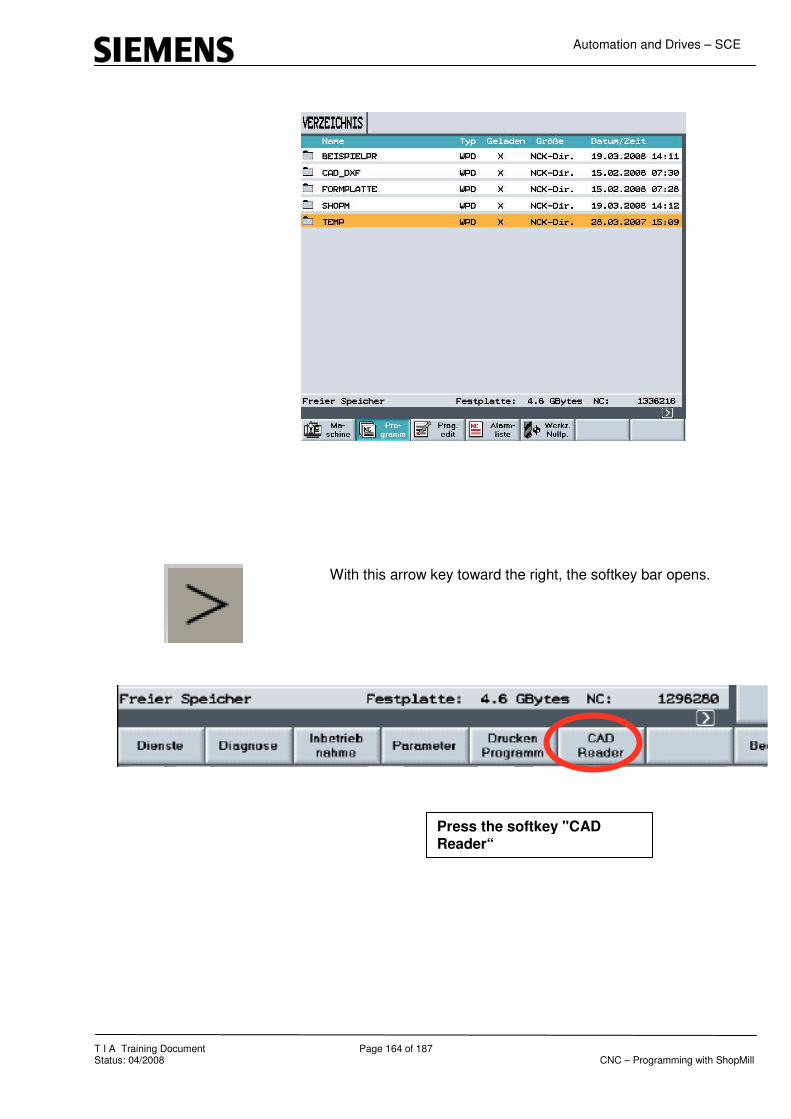
Automation and Drives – SCE
T I A Training Document Page 164 of 187 Status: 04/2008 CNC – Programming with ShopMill
With this arrow key toward the right, the softkey bar opens.
Press the softkey "CAD Reader“

Automation and Drives – SCE
T I A Training Document Page 165 of 187 Status: 04/2008 CNC – Programming with ShopMill
24.3 Opening a DXF Drawing from a File.

Automation and Drives – SCE
T I A Training Document Page 166 of 187 Status: 04/2008 CNC – Programming with ShopMill
24.4 Tooleiste
The tool bar can be selected by means of the global header with "View → Display Toolbar“
. Operation in General All functions of the CAD Reader can be operated with the keyboard as well as with the mouse. The right mouse key corresponds to the "ESCAPE“ function that can be used for resetting activated menus or functions. Operating sequence Open DXFfiles With Open, the selected CAD drawing is selected. Saving the generated program Generated contours can be saved as data type in the • MPF format (∗.mpf) • SPF format (∗.spf) • ARC format (∗.arc) (SINUMERIK archive) Back For contour tracking, the last action is reset corresponding to the selection element by element, or the last intersection is reset. .
„Tool l
Tool Bar

Automation and Drives – SCE
T I A Training Document Page 167 of 187 Status: 04/2008 CNC – Programming with ShopMill
24.5 Specifying the Zero Point
To output the contour as NC program, it is necessary to specify a zero point of the drawing because in most cases, it will deviate from the zero p point of the DXF file.
The following options are available to define the zero point: • Automatically to Element Center • Automatically to Element Start • Automatically to Element End • Direct input of the coordinates; for example X100, Y100 • Any position by selecting with the mouse
24.6 Contour Tracking
Setting the Contour Starting Point
Contour Tracking with starting point and end point
The starting and end point of the contour to be generated is selected in dependence of the initial position of the technology applied: • Automatically to Element Center • Automatically to Element Starting/Endpoint • Directly with mouse selection
Example
Element Center Element Start Element End Free Input Mouse Position
Element center Start/End point Mouse position

Automation and Drives – SCE
T I A Training Document Page 168 of 187 Status: 04/2008 CNC – Programming with ShopMill
1. Contour direction Results from specifying the starting point • and additional contour selection. Regarding contour tracking the attempt is made to select the contour automatically to the greatest extent possible. 2. Selection if there is a conflict If automatic contour tracking can no longer clearly determine a successor element, we switch to the interactive mode. The user is prompted to specify the next element with which the contour continues. 3. Full circle as contour With contour tracking, a full circle can be accepted in both directions. 4. Setting the end point An end point can be set to any selected contour tracking element, and accepted. Additional Notes • Full circles can be accepted as contour or as drilling points. • Contour tracking is canceled either with the keyboard with the "Esc“ key, or with the right mouse key. Setting the Contour Label Prior to contour tracking, labels can be set by entering starting labels and end labels. If a label is assigned twice, the CAD reader becomes interactive if the label was assigned once before. • For contour tracking in contours already selected • For appendixes to files if the label occurs already in the file.
Setting the contour end point Element center Element end point Mouse position Current position

Automation and Drives – SCE
T I A Training Document Page 169 of 187 Status: 04/2008 CNC – Programming with ShopMill
Setting Drilling Points 1. Full circle as hole A full circle can be selected with the function drilling points. The output of the generated G-code corresponds to the cycle format. Drilling Points Start 2. By selecting Drilling Pattern, drilling points can be parameterized as • Ay drilling position • According to the cycle • According to the cycle • According to the cycle Drilling Points End 3. Selected drilling points from the selection Drilling Pattern are accepted.
24.7 Influencing the Graphic Representation
Selecting the Processing Area: If the file includes many additional drawings -such as profiles, measurements, hatching, labelings, detail displays, frames etc.- the selection of a processing area, the number of elements can be reduced with a "Lasso“. Deselecting the Processing Area: The selections made in this processing area can be deselected.
Any position Row of holes Hole circle Grid of holes

Automation and Drives – SCE
T I A Training Document Page 170 of 187 Status: 04/2008 CNC – Programming with ShopMill
Zoom/Keys “+“ and “– “ You have the option to specify within a drawing a zoom area with the mouse key. By clicking on the symbol and using a "Lasso“ or with the keys “+“ and “–“ the display area is enlarged or reduced step by step. The display area can be moved using the cursor keys.
24.8 Editing Input Data
New Drawing/Spacer Bar Reads out the current drawing anew and optimized corresponding to the layer selection. Geometry With a mouse click, the coordinates for the selected element are read out according to the current zero point. If the button Edit appears in the display screen form, this element can be edited by selecting this button. Note This function is suitable for minor changes in the geometry to remedy inadequacies (particularly missing intersections) in the CAD drawing. For larger changes, the geometry processor is used. Once a change is made, it can not be reset. Layer Selection Initially, the selected DXF file is always shown with all its layers. If the file contains several layers, they are all shown in the basic view. However, layers that don’t contain data relevant to the contour can be hidden. Likewise, contours that are included in several layers can be selected by means of a selection screen form for contour tracking. The layer selection can not be undone.
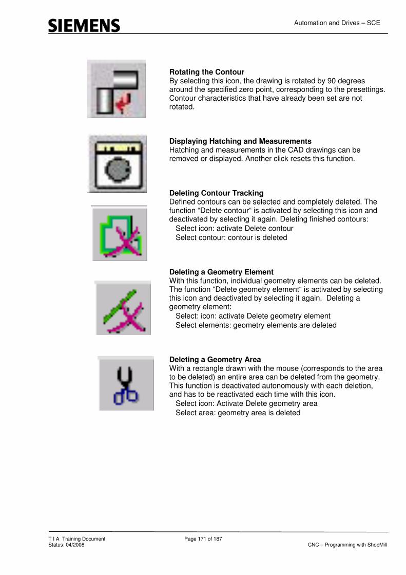
Automation and Drives – SCE
T I A Training Document Page 171 of 187 Status: 04/2008 CNC – Programming with ShopMill
Rotating the Contour By selecting this icon, the drawing is rotated by 90 degrees around the specified zero point, corresponding to the presettings. Contour characteristics that have already been set are not rotated. Displaying Hatching and Measurements Hatching and measurements in the CAD drawings can be removed or displayed. Another click resets this function. Deleting Contour Tracking Defined contours can be selected and completely deleted. The function “Delete contour“ is activated by selecting this icon and deactivated by selecting it again. Deleting finished contours:
� Select icon: activate Delete contour
� Select contour: contour is deleted Deleting a Geometry Element With this function, individual geometry elements can be deleted. The function “Delete geometry element“ is activated by selecting this icon and deactivated by selecting it again. Deleting a geometry element:
� Select: icon: activate Delete geometry element
� Select elements: geometry elements are deleted Deleting a Geometry Area With a rectangle drawn with the mouse (corresponds to the area to be deleted) an entire area can be deleted from the geometry. This function is deactivated autonomously with each deletion, and has to be reactivated each time with this icon.
� Select icon: Activate Delete geometry area
� Select area: geometry area is deleted

Automation and Drives – SCE
T I A Training Document Page 172 of 187 Status: 04/2008 CNC – Programming with ShopMill
24.9 Transferring Contour Elements to the Directory
-Save As -SI_Train -dh -wks.dir -Select directory where the contour is to be stored.
All contour elements are stored in the directory; for example, CAD_DXF.

Automation and Drives – SCE
T I A Training Document Page 173 of 187 Status: 04/2008 CNC – Programming with ShopMill
25 Sample Drawings - Milling
25.1 Mounting Plate

Automation and Drives – SCE
T I A Training Document Page 174 of 187 Status: 04/2008 CNC – Programming with ShopMill
25.2 Hole Plate

Automation and Drives – SCE
T I A Training Document Page 175 of 187 Status: 04/2008 CNC – Programming with ShopMill
25.3 Housing Lid

Automation and Drives – SCE
T I A Training Document Page 176 of 187 Status: 04/2008 CNC – Programming with ShopMill
25.4 Longitudinal Guide

Automation and Drives – SCE
T I A Training Document Page 177 of 187 Status: 04/2008 CNC – Programming with ShopMill
25.5 Example 1

Automation and Drives – SCE
T I A Training Document Page 178 of 187 Status: 04/2008 CNC – Programming with ShopMill
25.6 Injection Mould

Automation and Drives – SCE
T I A Training Document Page 179 of 187 Status: 04/2008 CNC – Programming with ShopMill
25.7 Measuring Part

Automation and Drives – SCE
T I A Training Document Page 180 of 187 Status: 04/2008 CNC – Programming with ShopMill
25.8 Pattern Plate

Automation and Drives – SCE
T I A Training Document Page 181 of 187 Status: 04/2008 CNC – Programming with ShopMill
25.9 Exercise 11

Automation and Drives – SCE
T I A Training Document Page 182 of 187 Status: 04/2008 CNC – Programming with ShopMill
26 Flange

Automation and Drives – SCE
T I A Training Document Page 183 of 187 Status: 04/2008 CNC – Programming with ShopMill
26.1 Clamping Plate

Automation and Drives – SCE
T I A Training Document Page 184 of 187 Status: 04/2008 CNC – Programming with ShopMill
26.2 Prism

Automation and Drives – SCE
T I A Training Document Page 185 of 187 Status: 04/2008 CNC – Programming with ShopMill
26.3 Kidney Plate

Automation and Drives – SCE
T I A Training Document Page 186 of 187 Status: 04/2008 CNC – Programming with ShopMill
26.4 Connecting Rod

Automation and Drives – SCE
T I A Training Document Page 187 of 187 Status: 04/2008 CNC – Programming with ShopMill
26.5 Wing