es120438 tool palettes: beyond the basics 1 es120438 tool palettes: beyond the basics justin johnson...
TRANSCRIPT

Page 1
ES120438
Tool Palettes: Beyond the Basics Justin Johnson GPD Group – Akron, OH
Description
Learn how to create, standardize, and distribute tool palettes within a company network or organization. For everyone from new CAD users to the more advanced CAD users, this session will help speed up efficiency and organize tools for team use. Learn about the basics of creating tools and adding them to palettes, organizing and naming the tools, saving and distributing palettes from a network location, and setting up LISP routines to switch between palette groups. See how these tools can streamline detailing across multiple users and help centralize CAD standards. The class will utilize several examples to walk through the process from start to finish. We’ll also discuss best practices and tool limitations.
Speaker(s)
Justin Johnson is a Design Team Manager for GPD Group, a multi-discipline nationwide architectural and engineering firm. Justin has 10 years of engineering industry experience and over 15 years of AutoCAD experience with his team. He started as a full-time CAD Designer while earning a Bachelor of Science in Construction Engineering from the University of Akron. He is an AutoCAD Certified Professional and a current member of the Autodesk User Group International (AUGI) and Construction Management Association of America (CMAA). During his tenure he has held the positions of CAD Designer, Drafting Team Leader and now Design Team Manager within the telecommunications division at GPD. In his current role he is responsible for drafting quality control, standards, process innovation, design tool innovation and IT integration tasks of his practice. In addition, Justin serves on the GPD CAD Standards and GPD Quality Control Committee’s whom act as technical liaisons for the company.
Learning Objectives
• Learn about the creation and naming of tools as well as palettes
• Learn how to organize the tools on the palettes
• Learn how to save and distribute palettes from a network location
• Learn how to set up LISP routines for commands to switch palettes

Page 2
Introduction- What, Who, and Why?
What are Palettes? Tool palettes are individual collections of tools that help provide access to a designated inventory of blocks, hatches, commands, and much more. AutoCAD introduced Tool Palettes in 2004 and typically comes with preset palettes and tools available for use. In this session we will be exploring how to create and set up our own custom palettes.
Who should use Tool Palettes? Everyone!! Most users do not take advantage of the benefits of using tool palettes and how they can help make life much easier as a designer/drafter. CAD managers can use Tool palettes to help aid in creating and maintaining company CAD standards. Why use Tool Palettes?
• Productivity, that’s the key word here. Easy access to customized tools can help users to be more productive in their workflow. Creating these tools will reduce the time spent looking for tools or searching for block libraries buried deep within the ancient folder directories of the past.
• Consistency is another benefit of using tool palettes. Having tools already created that comply with company standards will help ensure accuracy and consistency across your team. This will eventually lead back to productivity with less time spent worrying about items being drawn with the correct color, layer, scale or styles.
• Training is probably one of the least thought of ways that tool palettes can be utilized. Content tools including PDF materials and links to video content can be added to the palettes. Having all of your training material and CAD standards in on place can help lead us to consistency, since everyone will be able to access the “Standards”.
During this presentation we will discuss setting up a variety of tools, customizing the look and function of both palettes and the tools on the palettes, as well as ways we can share these tools within a company. We will also talk a bit about creating LISP routines and Macro commands to switch between Tool Palette groups containing different types of content. By the end of this presentation everyone should have a good working knowledge of Tool Palettes and be able to start setting up your own.
Page 3
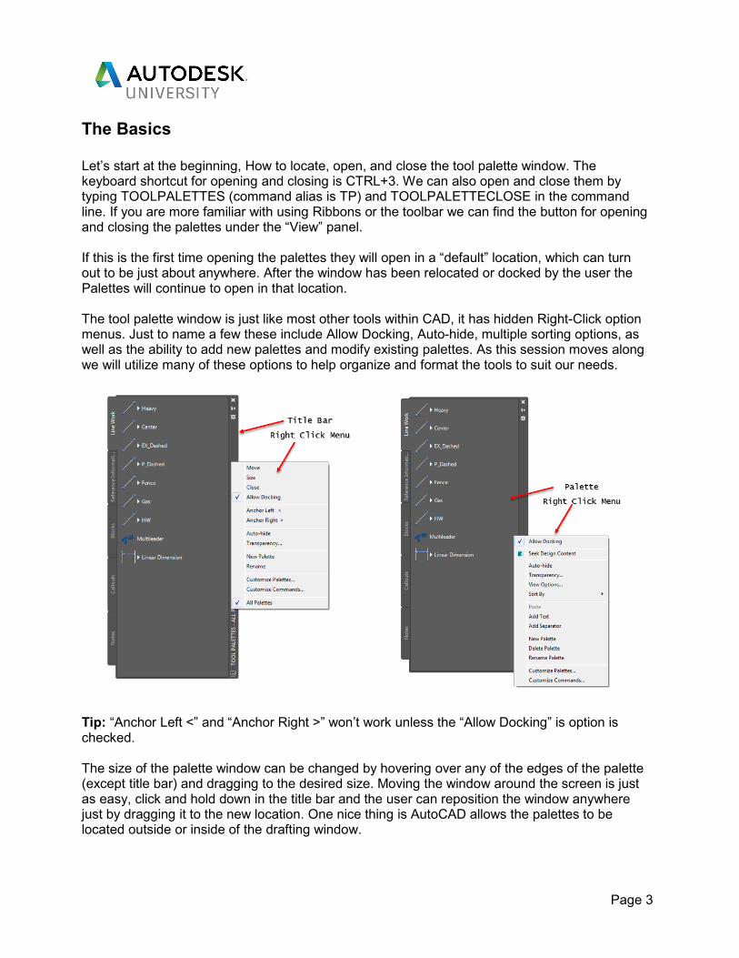
The Basics Let’s start at the beginning, How to locate, open, and close the tool palette window. The keyboard shortcut for opening and closing is CTRL+3. We can also open and close them by typing TOOLPALETTES (command alias is TP) and TOOLPALETTECLOSE in the command line. If you are more familiar with using Ribbons or the toolbar we can find the button for opening and closing the palettes under the “View” panel. If this is the first time opening the palettes they will open in a “default” location, which can turn out to be just about anywhere. After the window has been relocated or docked by the user the Palettes will continue to open in that location. The tool palette window is just like most other tools within CAD, it has hidden Right-Click option menus. Just to name a few these include Allow Docking, Auto-hide, multiple sorting options, as well as the ability to add new palettes and modify existing palettes. As this session moves along we will utilize many of these options to help organize and format the tools to suit our needs.
Tip: “Anchor Left <” and “Anchor Right >” won’t work unless the “Allow Docking” is option is checked. The size of the palette window can be changed by hovering over any of the edges of the palette (except title bar) and dragging to the desired size. Moving the window around the screen is just as easy, click and hold down in the title bar and the user can reposition the window anywhere just by dragging it to the new location. One nice thing is AutoCAD allows the palettes to be located outside or inside of the drafting window.

Page 4
Another feature in the right click menu that can be adjusted is transparency. This option will changes the opacity of the palette window allowing the user to see what is underneath. There really isn’t any major benefit to this option as AutoCAD doesn’t allow the user to do anything behind the Palette window.
Creating Palettes Folder Setup
Before we start building palettes we need to make sure AutoCAD will save the associated files in the correct location. This can be done a couple ways, we will start the simplest way and go into network solutions later on in the presentation. Create a new folder either on the desktop or on a network location. For the purpose of this session let’s call the folder “Build”. The folder name can really be anything that indicates its purpose but “Build” will relate to later on when we discuss how to share our tools. Once the folder has been created we need to change the default path for the folder location that AutoCAD uses to write the new palette information. This can be found within the AutoCAD options menu under the “Files” tab. Locate the folder Called “Tool Palettes File Locations”, click the “+” next to the folder to expand the folder and find the default path location as shown below. We can easily change the default file location shown and to where the new “Build” folder is located (i.e. C:\Users\...\Desktop\AU 17\Build). One way is by clicking the default location and then using the “Browse” button, this brings up a dialogue box and we can navigate to the folder location. We can also copy the location from windows explorer and paste it in to overwrite the default location. Overwriting the existing location will ensure that the palettes will be saved where we want them to be and not some random location AutoCAD picked.

Page 5
Click “Apply” and “OK” to exit. Notice that AutoCAD has set up a new folder called Palettes and added an .atc file to our “Build” folder. The name of this file will start with something along the lines of “New Palette_85L”. The default name for any new palette created in CAD will be similar to this before it is renamed in CAD. Adding Content to Palettes After the folders are created we can start the process of setting up our palettes and adding tools to them. We will explore a couple methods for doing this. The first is by using the drag and drop method from an open .dwg file. Any palatable item can be added to a tool palette from an open drawing as long as it has been saved within that open drawing. If it has been saved then simply click and hold the mouse button down then drag it to the desired tool palette to add it. Another method is using Design Center to add items to the tool palettes without opening the source file or folder. AutoCAD Blocks, image files, and hatch patterns saved to a .dwg file can be added through the design center window. Tip: All other palatable items need to be added from an open drawing file. Design center can be opened using the command alias “ADCENTER”. Under “Folder List” on the left hand side of the dialogue box (see below) navigate to the desired folder location or drawing file. Once the drawing of folder is active all of the available tools and images that can be added will appear on the right hand side of the window. These items can then be added by using the drag and drop method to bring individual items over to the desired tool palette window. Tip: We can also right click on a folder location and use the “Search” option to locate files.

Page 6
Design center also allows us to be able to add an entire library from a folder or file with one simple click. Right-click on the desired folder or file and find “Create Tool Palette” or “Create Tool Palette of Blocks” and watch the magic happen. A new palette is created of all of the palatable items. The tools will be named as they are within the associated files and the palette will be named to match the folder or .dwg file name depending on which was selected. Tip: Simply dragging and dropping the folder or .dwg file to the palette window will also create a new palette from the palatable items. Tip: Make sure any unwanted items are purged from the drawing file and all tools are named before creating a palette. No need to create extra work for ourselves deleting tools we didn’t mean to add.
Tool Palette Content Block Tools Dynamic blocks, standard blocks, and images can all be added to a palette and are what we will refer to as “Block” tools. Block tools can be inserted by using both the drag and drop method from an open CAD file or using Design Center as we discussed before. In addition to those methods blocks can also be inserted from Windows explorer and Internet browser. Dynamic Standard Tip: Dynamic blocks have a lightning bolt to designate the difference from a standard block. In addition to the block tools listed above we can also add External References (X-ref) onto tool palettes. Simply drag the created X-ref from an open file onto the desired to palette and it is now easily accessible. No more having to re-navigate the system to insert a new X-ref. By using tool palettes we can relocate the block libraries that were created way back in the day and are possibly stored in multiple drawings to one central location. This in turn eliminates time spent searching for that one block you know was made but can’t seem to remember which file it was in.

Page 7
Command Tools Instead of adding an entire Ribbon or Toolbar to a user’s CAD interface so that one button they use is available, we can add those needed commands to a palette. Both standard and custom commands can both be added to palettes. Adding commands to a palette rather than using the CUI to add new Ribbons, or panels will help reduce the amount of space taken up in the CAD Window. Commands can be added to palettes in two ways, one way being to simply drag and drop the item from an open CAD file. This method is good for creating line types, leaders, and dimension styles that are already defined with the company standards. The commands on the palette are saved using the layers, colors, and/or line types that they were created with. The second way is to open the CUI and again simply dragging the commands from the dialogue box to the Tool Palette. Commands added using this method will be more generic compared to adding them from an open .dwg file meaning they won’t have company standards assigned to them. Hatch Tools Hatch patterns can be added to tool palettes as well and just like all of the other tools we can preset the scale, layer, rotation, etc. that we need. We can also add hatches from drawing file through the design center or individually from an open drawing file. To add hatches within an open drawing file just simply use the drag and drop method to save an existing pattern to the palettes.

Page 8
We can also use the design center to add an entire hatch library to a palette. Inside the Design center dialogue box we first need to navigate to the folder or drawing file containing the hatch patterns we want to add. Right click on that folder or file and click “Search”. In the dialogue box here we can search for “Hatch Pattern Files” or “Hatch Patterns”. Once Design Center locates the Hatch files we can add the patterns similar to other tools. Click on one of the .pat files and the associate patterns will populate on the right hand side. Drag and drop any of the patterns from this window onto the palettes. We can also right click on the file to create an entire palette of the associated Hatch patterns at once. Additional Content Tools Links and references to outside sources including PDF documents and training videos can also be added to Tool Palettes. This content will open in your default web browser and provides easy access to reference material you might want to share. Creating tools like this will help centralize the content as well as make sure each user had access to the same information. Creating a shortcut to open content from a Tool Palette requires some knowledge of macros but is fairly simple. Right click over the palette window and choose “Customize commands”, within the search box type “script”. Once found drag and drop the Script command onto your palette, and yes do this before changing anything. Now close out of the command dialogue box and right click on your new tool to open ‘properties’. To add the macro, right click on the tool and choose ‘Properties’. Now add the following text to the ‘Command String’ field: ^C^C_.browser;"T:/Resources_2017/CAD_Standard.pdf"; Since this isn’t a “Programming” class so we won’t dive too much into the specifics but to give an idea here is what this command does, most of this can be applied to other macros. First the command clears active commands twice (^C^C), next it defines the command (.) function to open the default web browser (browser). After the semi-colon (;) we need to list the path to the content in quotation marks.

Page 9
When you are done, click ‘OK’ to close the Tool properties window and click on the button to try it out. If we’ve got this right, your default web browser will now open the ‘CAD_Standard.pdf” document. Tip: We will need to switch the back slash (\) to a forward slash (/) in the path to the content. Back slash will add a pause for user input to the command.
Modifying the New Tools All of the tools have their own right-click menu options for additional ways to customize the look and function of the tools. A majority of the options in the menu are your basic customizing options such as cut, copy, paste, and move. The “Properties” menu is where most of the magic happens. The menu options will change slightly based on which tool is selected. The following image shows a couple examples of the properties windows. Using these menus we can change the tool properties without opening the source file. Earlier we discussed setting up the tools using company standards before adding them to the tool palettes, that’s still the best method. These options will allow us to customize the tools for the one-off situations where we might need the tool to be slightly different. The ability to set the scale factor or rotation the object will be inserted before we add it to the drawing are probably two of the more beneficial options found in the menus. These properties will begin the next time the tool is inserted and will not change any previous properties that a tool was inserted with. They will continue to be inserted with the most recent properties until they are changed again

Page 10
A few other items within the menu include Fly-out options, command strings (macros), Description, and visibility state options. Fly-out options give us the ability to set which tools will be available from the drop down list when available. A tool with these options will always start with the full list checked and by unchecking them we can eliminate the ones we may not use. Tip: Giving a tool a description will show up as a tool tip when you hover over it on the palette. Moving and copying tools In an active palette a tool can be moved by clicking and dragging it to a new location. The new location is indicated by a bold line, the tool being moved will also appear as a silhouette above the line. The user can also copy tools from one palette to another by using the copy or cut commands, cut will automatically remove the tool from its current palette. Paste will make a copy or relocate the tool to another desired location. All of this is very similar to using any Microsoft based programs. Changing the Looks AutoCAD has built in the ability to customize the looks of the tools to suit the individual user. Right clicking in the palette window and selecting “View Options” and you will get the dialogue box on the right. Here we can change the tool Image size and what is shown for the tool. Once the user is done making changes simply choose whether they are to be made to the Current Palette or to all Palettes in the dropdown menu and click OK. These changes can be made by the user even if the tool palette itself is locked. TIP: Custom tool images and user defined images are saved in a folder with the palettes called ‘Images’.

Page 11
Tool Organization Tool Dividers Sometimes there might be a need to separate the tools or we might want to organize them on the palette so the content is easier to manage. There are two items within the right-click menu that can help us achieve this, “Line Separator” and “Text Object”. To add a line separator right click in the palette window and select “Add Separator”. The line will be added to the window at the location that you clicked, don’t worry it can be moved. Just like all of the other tools we simply just click and drag the line to where it is needed.
Now that the tools are separated we might need to let the users of the content know what the line is separating. We can add a text description near the line to help to clarify what comes next. In the same manner as adding the line separator just right click and select “Add Text”. Change the default “New Text” to whatever description is needed and click anywhere outside of the text box. This also can be moved easily by clicking and dragging to a new location. Re-arranging Tools When you re-arrange tools on a palette, AutoCAD doesn’t overwrite the original format of an existing palette. So any changes you have made to the tool order will not be the same when AutoCAD is restarted, annoying right? AutoCAD saves the changes order in what is called a display file and it is not a permanent change to the palette order. This file is stored locally and will not share to other users. There is good news!!! The fix for this is easy:
1. Make your changes to the desired palette. 2. Click once with the left mouse button anywhere on the palette 3. Use CTRL+A to select everything on the palette. 4. Use CTRL+X to cut all the tools on the palette 5. Create a new palette and name it accordingly 6. Use CTRL+V and paste the tools to the new palette 7. Delete the old Palette 8. Save and close to write the changes out

Page 12
Cutting and pasting the tools back in forces AutoCAD to save the tools in the current order and deleting the old palette will remove duplicate palettes and tools. Saving Changes I have mentioned throughout this tutorial, and will continue to, the importance of saving and closing AutoCAD when changes are made to the palettes. This is the only way AutoCAD will keep the changes that we have worked so hard on. At the same time that saving is a benefit is can also be a curse. If everyone has access to the new palettes that were created then everyone can change them. This is where locking and sharing them comes in handy.
Tool Palette Distribution Simply put this next section is probably the most important to all of us, sharing these great tools we have just set up with the rest of the company. There are many ways to do this and how you set them up at your company depends of the format and how much control you have over network folders. Hopefully everyone has a great IT department to help you out. Import/Export Palettes First, the simple method, using the “ImportL” and “ExportL” functions within the “Customize Palettes” option. To start right-click on the palette title bar and find “Customize Palettes” and you will see the below dialogue box open. Once in here we can then right click on the desired palettes and choose what we want to do. The manager or palette creator can “Export” the palette to a shared folder on the network and then notify the user(s) that it is available. Exporting the palette creates an .xtp file in the selected folder location. The user(s) will then have to locate the same menu from the palettes, select “Import”, navigate to the folder on the network, and finally select the palette file. It does have its benefits for smaller applications but can be a more tedious way of sharing palettes for larger groups.

Page 13
Import/Export Palette Groups Sometimes we will want to “group” palettes together based on the type of work we are completing or content that relates to each other. Using the group function we can do just that. In the previous photo on the right hand side of the window titled “Palette Groups”, right click here and select “New Group”. Give the new group a name that indicates the tools that will be saved on it. Once the group is available it is easy to add the palettes from the left side to the group on the right. Simply just click and drag the palette from the left hand column and drop it under the group you want to add it to. Palette groups can be imported and exported for sharing in the same manner as individual palettes. Tip: The individual palettes need to be imported before the palette groups or the groups will not load properly. Loading Palette Groups We can make switching between palette groups easier by using Macros to set up custom commands that will change the palette file location. Under the manage tab find the “Action Recorder” panel and hit record. At the command line type “*_toolpalettepath”, we then get prompted to enter a new location for the tool palettes. We can copy the file path from Windows explorer and paste it into the command line and then hit “Enter”. Once completed click stop on the Ribbon and the “Action Macro” dialogue box will open. Tip: The command *_toolpalettepath is a hidden command, using the * first indicates a hidden variable to CAD. In this window we can give the macro a command name, view the folder path, and give a description. Once we are satisfied with the options here click OK, the macro is now stored with the command name you gave it. As a word of caution if the name given is the same as an existing command or alias in AutoCAD it will overwrite the existing one.

Page 14
Now loading the palette group is easy as typing in the command name and the file path will be changed. We can also add these new commands as buttons on our tool palettes using the “Run Script” command and adding the script into the tool to save it to the palette. Tip: Writing out the command steps in word or txt document can speed up the Action Recording process. You can just copy and paste the text into the command line to record the process. Network Sharing of Palettes The previous methods discussed are good for just about any user and in about any situation. The next couple ways we are going to discuss are for sharing Palettes over a company network. We should have already saved our “Build” folder to a shared network location. If not that is the first step that needs to be done to share across a network. Assuming we have created all of our Tools the next step is to create another folder in the same directory as the “Build” folder, let’s call this one “Deploy”. Copy the content of the Build folder and paste it into the new “Deploy” folder. All of our .atc files and the “Images” folder should now be in this folder. Now we want to lock our palettes to protect other users from changing them. To do this right-click on the palettes that need locked (or ctrl+A for all) and select “Properties”. Within the properties window, under the “General” Tab, find the “Read-Only” box and click the box. Close out and restart CAD and the palettes will now be locked for editing To make this method work all other users will need to have their palette file location set to the “Deploy” folder. This method is good for networks where all users have access to save files in the network folder.
Page 15
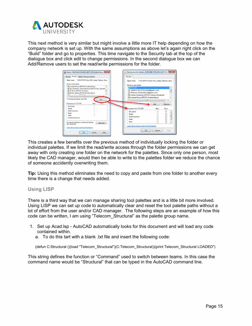
This next method is very similar but might involve a little more IT help depending on how the company network is set up. With the same assumptions as above let’s again right click on the “Build” folder and go to properties. This time navigate to the Security tab at the top of the dialogue box and click edit to change permissions. In the second dialogue box we can Add/Remove users to set the read/write permissions for the folder. This creates a few benefits over the previous method of individually locking the folder or individual palettes. If we limit the read/write access through the folder permissions we can get away with only creating one folder on the network for the palettes. Since only one person, most likely the CAD manager, would then be able to write to the palettes folder we reduce the chance of someone accidently overwriting them. Tip: Using this method eliminates the need to copy and paste from one folder to another every time there is a change that needs added.
Using LISP There is a third way that we can manage sharing tool palettes and is a little bit more involved. Using LISP we can set up code to automatically clear and reset the tool palette paths without a lot of effort from the user and/or CAD manager. The following steps are an example of how this code can be written, I am using “Telecom_Structural” as the palette group name. 1. Set up Acad.lsp - AutoCAD automatically looks for this document and will load any code
contained within. a. To do this tart with a blank .txt file and insert the following code:
(defun C:Structural ()(load "Telecom_Structural")(C:Telecom_Structural))(print Telecom_Structural LOADED")
This string defines the function or “Command” used to switch between teams. In this case the command name would be “Structural” that can be typed in the AutoCAD command line.
Page 16
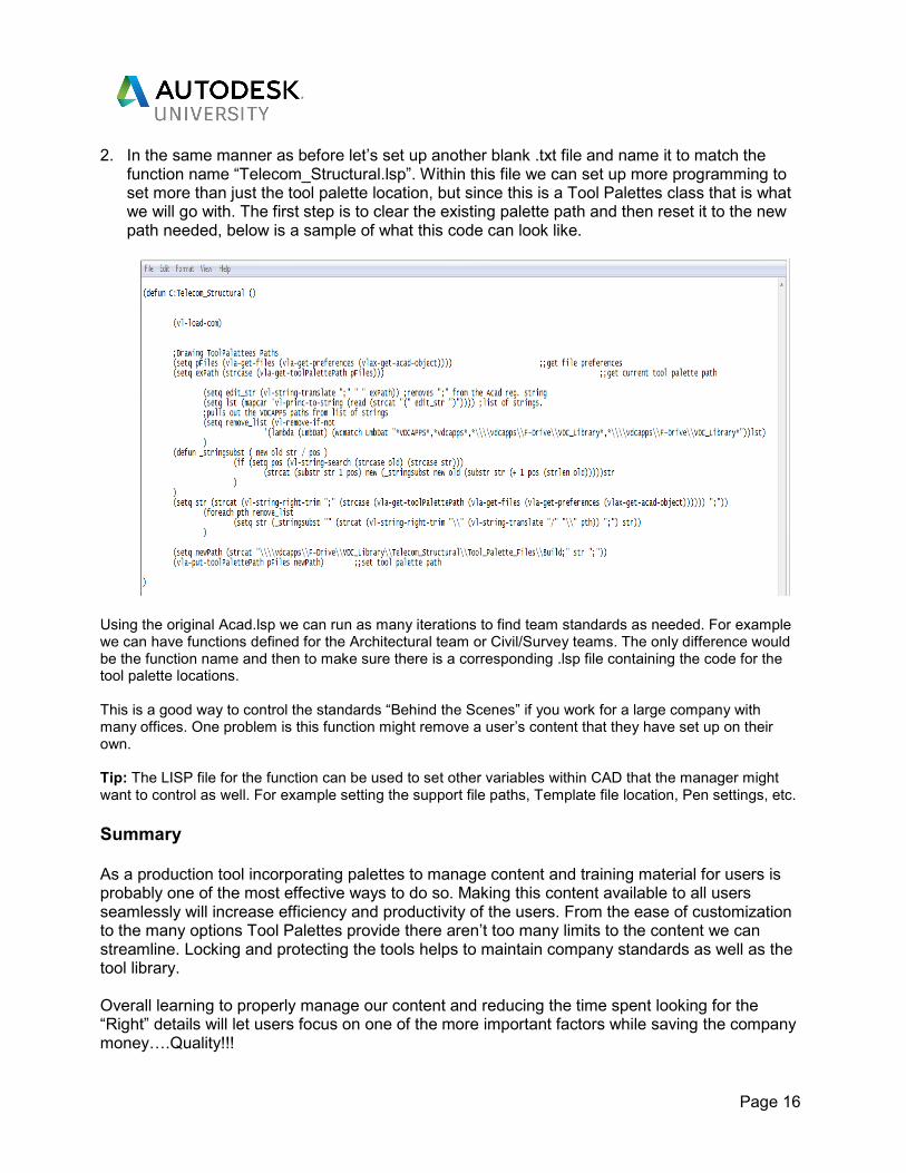
2. In the same manner as before let’s set up another blank .txt file and name it to match the function name “Telecom_Structural.lsp”. Within this file we can set up more programming to set more than just the tool palette location, but since this is a Tool Palettes class that is what we will go with. The first step is to clear the existing palette path and then reset it to the new path needed, below is a sample of what this code can look like.
Using the original Acad.lsp we can run as many iterations to find team standards as needed. For example we can have functions defined for the Architectural team or Civil/Survey teams. The only difference would be the function name and then to make sure there is a corresponding .lsp file containing the code for the tool palette locations. This is a good way to control the standards “Behind the Scenes” if you work for a large company with many offices. One problem is this function might remove a user’s content that they have set up on their own. Tip: The LISP file for the function can be used to set other variables within CAD that the manager might want to control as well. For example setting the support file paths, Template file location, Pen settings, etc.
Summary As a production tool incorporating palettes to manage content and training material for users is probably one of the most effective ways to do so. Making this content available to all users seamlessly will increase efficiency and productivity of the users. From the ease of customization to the many options Tool Palettes provide there aren’t too many limits to the content we can streamline. Locking and protecting the tools helps to maintain company standards as well as the tool library. Overall learning to properly manage our content and reducing the time spent looking for the “Right” details will let users focus on one of the more important factors while saving the company moneyL.Quality!!!