es17657-l integrating structural design, analysis, and...
TRANSCRIPT
Page 1
ES17657-L
Integrating Structural Design, Analysis, and Detailing: Advance Steel and Robot Structural Analysis Aaron M. Vorwerk, AIA, NCARB, EIT, LEED AP BD+C Autodesk, Inc. Stephen Bessette Autodesk, Inc.
Description
In this hands-on lab, we will explore the new interoperability between Advance Steel 2017 software and Robot Structural Analysis Professional 2017 software. We will begin by exploring a simple structural model in Advance Steel software. We will push that model into Robot Structural Analysis Professional software and perform a basic analysis and code group-based design. Once the design is correct, we will update the Advance Steel model geometry from Robot Structural Analysis Professional and continue the steel-detailing process. This session features Robot Structural Analysis Professional and Advance Steel.
Your AU Expert(s)
Aaron Vorwerk is a registered architect, civil/structural engineer-in-training, LEED accredited professional, and AEC industry technology evangelist. A senior technical sales specialist with Autodesk, Inc., Aaron influences customer BIM workflow adoption and strategy as a trusted advisor and serves as a lecturer, panelist, and author on BIM-related topics. Vorwerk holds graduate degrees in architecture and engineering (MArch, MSCE, BSCE) and has acquired widespread experience in architecture, engineering, and construction over the past 20 years, including leading Revit software transition efforts in two design firms. Stephen Bessette is a technical sales specialist for Autodesk, Inc., specializing in the BIM 360 platform, Navisworks, Revit, and Advance Steel. A graduate of the NHTI Architectural Engineering Technology program, as well as a certified computer-aided draftsman, Bessette has over 15 years of experience within the design and construction industry, including fire protection design, residential design, construction management and estimating, land surveying, quality control of construction materials, and structural steel inspection.
Learning Objectives
Learn how to create and manipulate model geometry in Advance Steel
Learn how to send Advance Steel models to Robot Structural Analysis and back for analysis
Learn how to perform code group-based design in Robot Structural Analysis
Learn how to add connections, number parts, and generate drawings in Advance Steel
Page 2
Structural Tools and Workflows
There are literally hundreds of product offerings in the Autodesk portfolio, dozens of which are applicable to the AEC industry to some degree. With that in mind, let’s start by sorting out the most appropriate tools for typical structural engineering workflows.
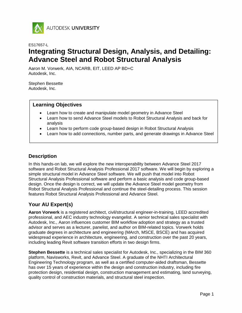
The Autodesk Structural Toolbox A general representation of Autodesk tools that might be used in structural workflows (i.e. building and plant/industrial workflows, specifically) is shown in Fig. 1.
Figure 1: Autodesk tools by phase for structural engineering and fabrication
To be clear, the mix of tools employed on every project will vary. Not all of these tools will be used on every project; conversely, Autodesk offers products not listed here capable of providing additional design, analysis, and delivery capabilities if needed. But for typical engineering projects, and Autodesk-centric workflow will begin with one of two products: Advance Steel (commonly used for plant/industrial steel structures, as well as buildings) or Revit (broadly used for buildings and civil structures). The two products offer bidirectional synchronization, so they’re not mutually exclusive either. A third tool that might be paired with Advance Steel or Revit on the front end of the work process is Dynamo, an open source visual programming language developed by Autodesk and used to enable powerful computational design and the automation of routine tasks (without requiring coding knowledge) in Autodesk and third-party tools. See http://dynamobim.org/.
As a project moves from early design into analysis, Robot Structural Analysis Professional comes into play. Robot Structural Analysis Professional (aka RSA or Robot) is a powerful general-purpose finite element analysis (FEA) platform that exchanges information directly with Advance Steel via the SMLX format. RSA also offers full bidirectional interoperability with Revit.
Page 3
Moving further into the structural workflow, coordination tools begin to play a larger role. These may include the BIM 360 platform (see http://www.autodesk.com/products/bim-360/overview) and very likely Navisworks (http://www.autodesk.com/products/navisworks/overview).
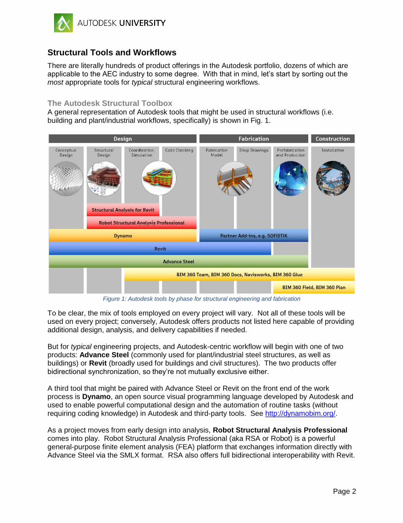
Steel Design and Detailing Workflow
Figure 2: Bridge model viewed in RSA
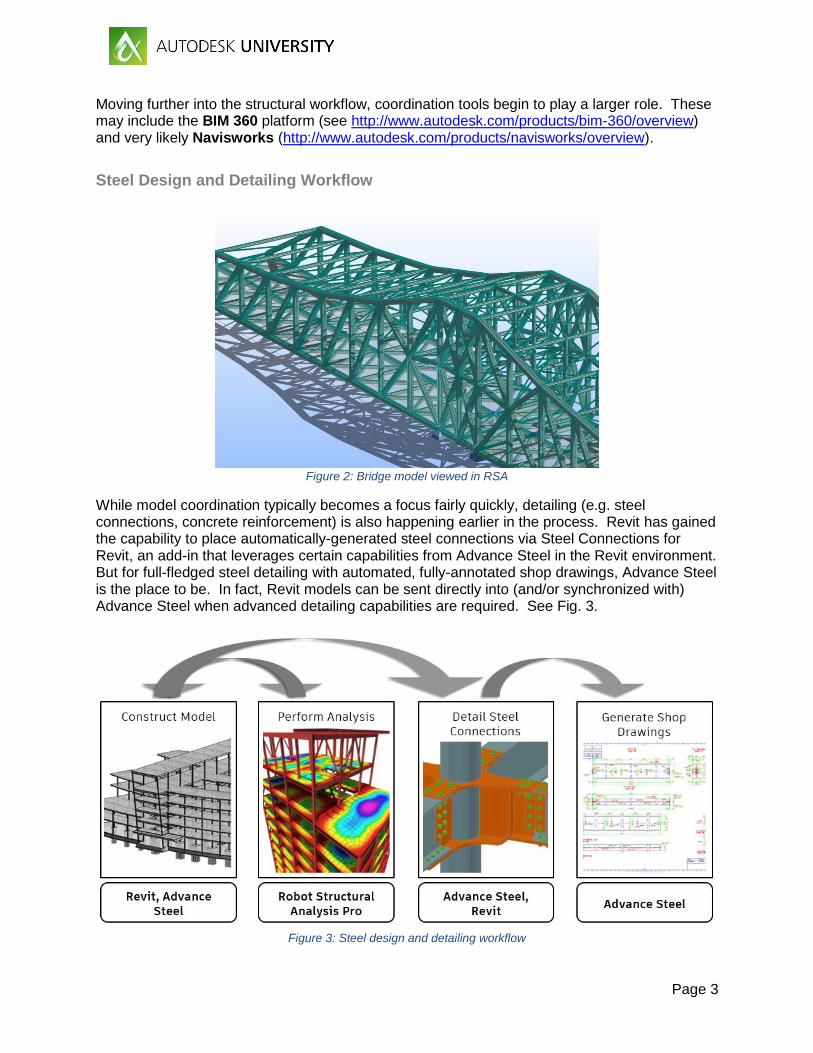
While model coordination typically becomes a focus fairly quickly, detailing (e.g. steel connections, concrete reinforcement) is also happening earlier in the process. Revit has gained the capability to place automatically-generated steel connections via Steel Connections for Revit, an add-in that leverages certain capabilities from Advance Steel in the Revit environment. But for full-fledged steel detailing with automated, fully-annotated shop drawings, Advance Steel is the place to be. In fact, Revit models can be sent directly into (and/or synchronized with) Advance Steel when advanced detailing capabilities are required. See Fig. 3.
Figure 3: Steel design and detailing workflow
Page 4
As projects continue to move downstream in the process, information captured during structural design, analysis, and detailing phases can be utilized and supplemented during fabrication and installation using BIM 360 Field. This information, together with commissioning data, can be populated at the click of a button into Building Ops to support owner warranty, operations and maintenance activities from the date of delivery. The focus of this session is primarily on the front end of the workflow. In the sections to come, we will be exploring structural steel modeling in Advance Steel, followed by structural analysis and code group design in Robot Structural Analysis Professional, and then we will return Advance Steel for detailing and documentation.
Page 5
Autodesk Advance Steel 2017
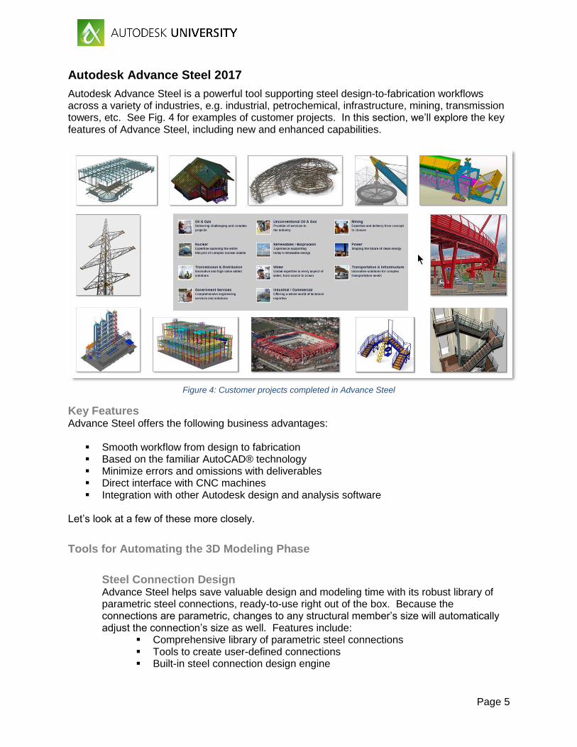
Autodesk Advance Steel is a powerful tool supporting steel design-to-fabrication workflows across a variety of industries, e.g. industrial, petrochemical, infrastructure, mining, transmission towers, etc. See Fig. 4 for examples of customer projects. In this section, we’ll explore the key features of Advance Steel, including new and enhanced capabilities.
Figure 4: Customer projects completed in Advance Steel
Key Features Advance Steel offers the following business advantages:
Smooth workflow from design to fabrication Based on the familiar AutoCAD® technology Minimize errors and omissions with deliverables Direct interface with CNC machines Integration with other Autodesk design and analysis software
Let’s look at a few of these more closely.
Tools for Automating the 3D Modeling Phase
Steel Connection Design Advance Steel helps save valuable design and modeling time with its robust library of parametric steel connections, ready-to-use right out of the box. Because the connections are parametric, changes to any structural member’s size will automatically adjust the connection’s size as well. Features include:
Comprehensive library of parametric steel connections Tools to create user-defined connections Built-in steel connection design engine
Page 6
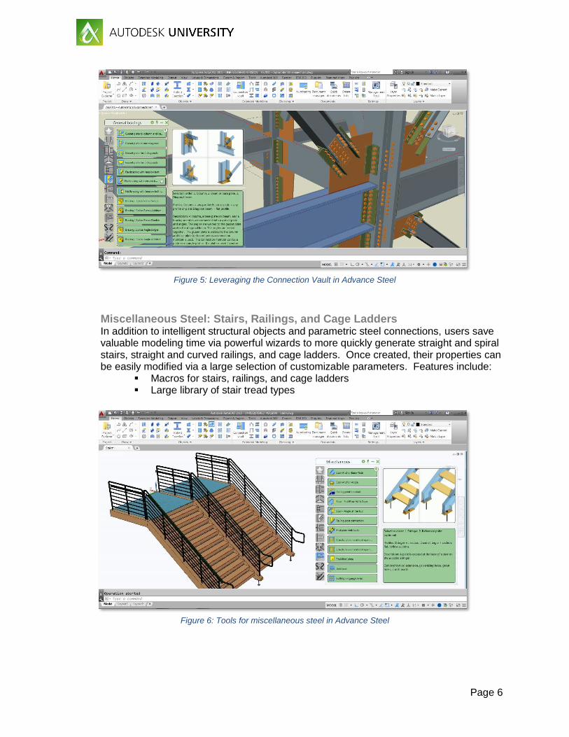
Figure 5: Leveraging the Connection Vault in Advance Steel
Miscellaneous Steel: Stairs, Railings, and Cage Ladders In addition to intelligent structural objects and parametric steel connections, users save valuable modeling time via powerful wizards to more quickly generate straight and spiral stairs, straight and curved railings, and cage ladders. Once created, their properties can be easily modified via a large selection of customizable parameters. Features include:
Macros for stairs, railings, and cage ladders Large library of stair tread types
Figure 6: Tools for miscellaneous steel in Advance Steel
Page 7
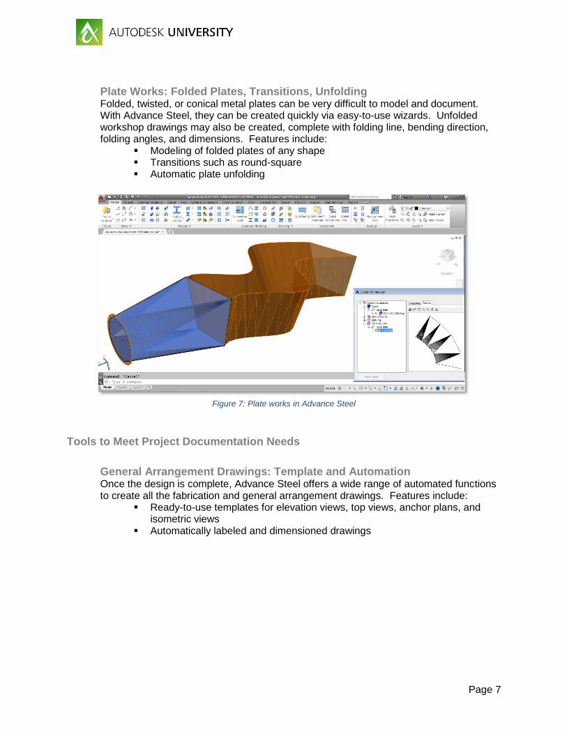
Plate Works: Folded Plates, Transitions, Unfolding Folded, twisted, or conical metal plates can be very difficult to model and document. With Advance Steel, they can be created quickly via easy-to-use wizards. Unfolded workshop drawings may also be created, complete with folding line, bending direction, folding angles, and dimensions. Features include:
Modeling of folded plates of any shape Transitions such as round-square Automatic plate unfolding
Figure 7: Plate works in Advance Steel
Tools to Meet Project Documentation Needs
General Arrangement Drawings: Template and Automation Once the design is complete, Advance Steel offers a wide range of automated functions to create all the fabrication and general arrangement drawings. Features include:
Ready-to-use templates for elevation views, top views, anchor plans, and isometric views
Automatically labeled and dimensioned drawings

Page 8
Figure 8: General arrangement drawings in Advance Steel
Fabrication Deliverables: Shop Drawings, BOMs, and CNC Data Users may create bill of materials using predefined and custom formats. Advance Steel also automatically generates CNC (Computer Numeric Control) files (DSTV format) for workshop machines, such as welding robots, allowing the direct data transfer from the 3D model to fabrication. Features include:
Single part and assembly drawings Bills of materials (BOMs) DSTV, DXF, and KISS files
Figure 9: Single part and assembly drawings in Advance Steel
Page 9
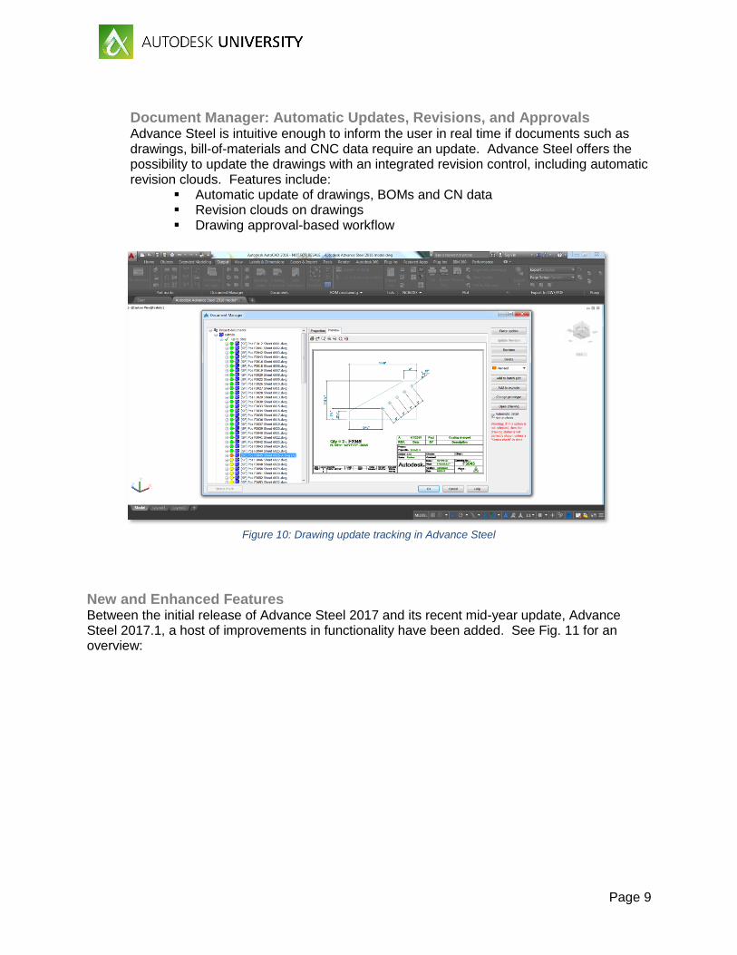
Document Manager: Automatic Updates, Revisions, and Approvals Advance Steel is intuitive enough to inform the user in real time if documents such as drawings, bill-of-materials and CNC data require an update. Advance Steel offers the possibility to update the drawings with an integrated revision control, including automatic revision clouds. Features include:
Automatic update of drawings, BOMs and CN data Revision clouds on drawings Drawing approval-based workflow
Figure 10: Drawing update tracking in Advance Steel
New and Enhanced Features Between the initial release of Advance Steel 2017 and its recent mid-year update, Advance Steel 2017.1, a host of improvements in functionality have been added. See Fig. 11 for an overview:
Page 10
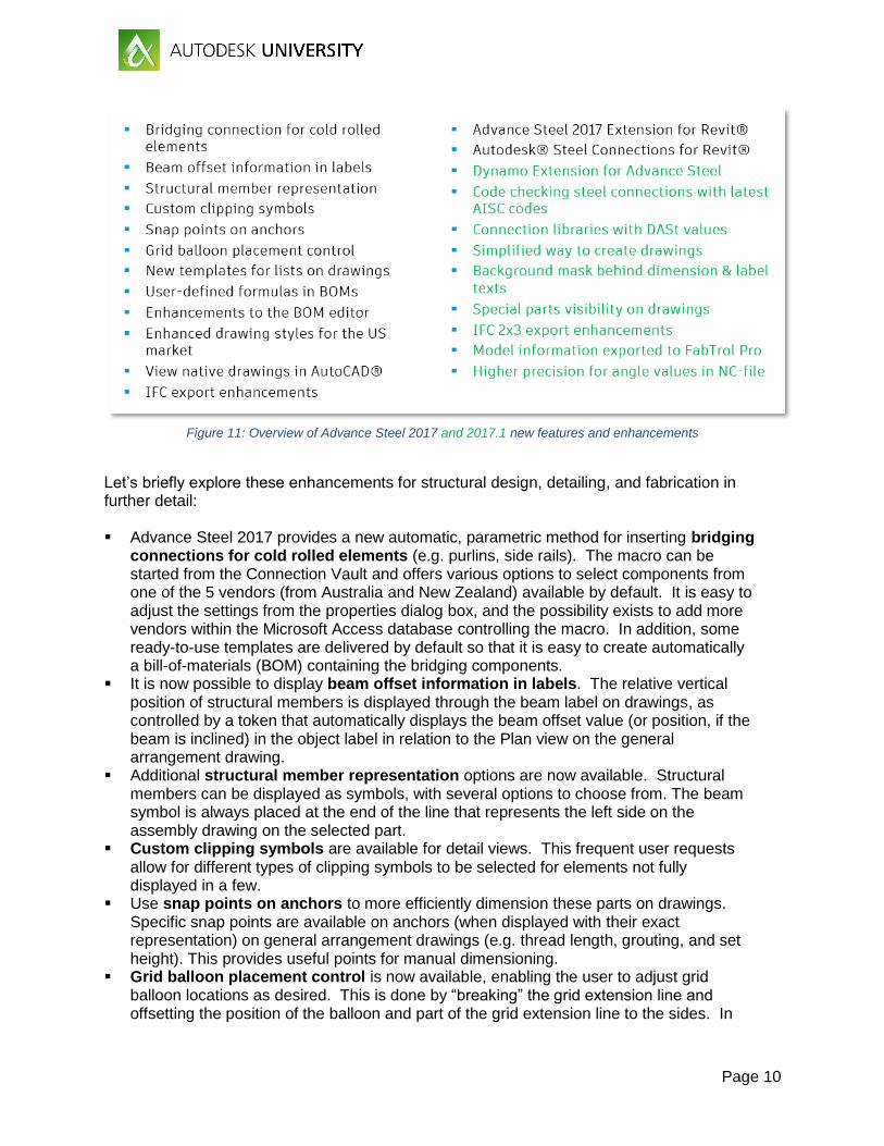
Figure 11: Overview of Advance Steel 2017 and 2017.1 new features and enhancements
Let’s briefly explore these enhancements for structural design, detailing, and fabrication in further detail: Advance Steel 2017 provides a new automatic, parametric method for inserting bridging
connections for cold rolled elements (e.g. purlins, side rails). The macro can be started from the Connection Vault and offers various options to select components from one of the 5 vendors (from Australia and New Zealand) available by default. It is easy to adjust the settings from the properties dialog box, and the possibility exists to add more vendors within the Microsoft Access database controlling the macro. In addition, some ready-to-use templates are delivered by default so that it is easy to create automatically a bill-of-materials (BOM) containing the bridging components.
It is now possible to display beam offset information in labels. The relative vertical position of structural members is displayed through the beam label on drawings, as controlled by a token that automatically displays the beam offset value (or position, if the beam is inclined) in the object label in relation to the Plan view on the general arrangement drawing.
Additional structural member representation options are now available. Structural members can be displayed as symbols, with several options to choose from. The beam symbol is always placed at the end of the line that represents the left side on the assembly drawing on the selected part.
Custom clipping symbols are available for detail views. This frequent user requests allow for different types of clipping symbols to be selected for elements not fully displayed in a few.
Use snap points on anchors to more efficiently dimension these parts on drawings. Specific snap points are available on anchors (when displayed with their exact representation) on general arrangement drawings (e.g. thread length, grouting, and set height). This provides useful points for manual dimensioning.
Grid balloon placement control is now available, enabling the user to adjust grid balloon locations as desired. This is done by “breaking” the grid extension line and offsetting the position of the balloon and part of the grid extension line to the sides. In
Page 11
addition, a new option enables placing grid line symbols and balloons at the top in Elevation views. The balloon size may also be kept equal on the sheet, and text size may be decreased to fit the balloon borders.
In Advance Steel 2017, a new template for lists on drawings is available, providing connection location information on single part drawings. This indicates whether parts are shop-welded, shop-bolted, or both.
It is now possible to include user-defined formulas in BOMs, such as addition, subtraction, multiplication and division. All used tokens in a line can be part of the calculation. The result is then automatically calculated and appears in the obtained BOM. This helps users add, for example, an extra 5% to a bolt quantity to be shipped to the site.
Additional enhancements to the BOM editor include a filter tool making it easy to find the tokens by name, as well as options to sort individual tokens within a sorting dialog box.
Included with Advance Steel 2017 are enhanced drawing styles for the US market. Drawing styles for engineering drawings have been enhanced and are now available within a new category in the Drawing Styles tool palette. A set of additional drawing styles for creating drawings of miscellaneous steel such as stairs, railings and cage ladders are also provided. This helps produce drawings with less cleanup required than previous releases of Advance Steel.
The Advance Steel 2017 object enabler makes it possible to view native drawings in AutoCAD 2017 or AutoCAD LT 2017, as well as in BIM360, A360 and AutoCAD 360. Drawing content cannot be modified, but AutoCAD dimensions or annotations will snap to objects displayed within the drawing. This also means that you can use different Autodesk viewers for drawing revision marks, comments and review, while the drawings are still connected to the Advance Steel 3D model.
IFC export enhancements include the transfer of additional content, e.g. custom sections and curved elements. These features may be used to share more information with other software and improve workflows by enabling broader reuse of information from the Advance Steel detailed model.
The Advance Steel 2017 Extension for Revit enables bidirectional change management between Autodesk Revit and Advance Steel, available on the Autodesk App Store. The 2017 extension comes with various enhancements providing a higher level of exchange of model information, especially with the synchronization of Revit models containing steel connections back and forth with Advance Steel.
Autodesk Steel Connections for Revit provides access to a variety of parametric steel connections in Autodesk Revit software, enabling connections to be modeled with a higher level of detail. The application also includes a built-in steel connection design engine based on US and European codes. This functionality helps to bridge the gap between design and fabrication as both members and connections can be synchronized between Revit and Advance Steel for detailing. With Steel Connections for Revit, users can take advantage of model-based collaboration to create better coordinated designs and documentation that extends to fabrication.
The Dynamo Extension for Advance Steel is a visual programming extension that helps structural engineers drive the geometry and behavior of Advance Steel elements from Dynamo, including parametric complex structures that would be time-consuming in native Advance Steel. With its graphic interface, the Dynamo Extension offers the possibility to help drive the 3D modelling of straight & curved beams, but also planar plates of any shapes. In addition, Advance Steel properties such as beam section, material and user attributes can be controlled within the Dynamo environment.
Page 12
In an effort to maintain compliance with the latest standards, Advance Steel now performs code checking steel connections with latest AISC codes. The AISC code check was updated from the 13th to the 14th edition, and each calculation now includes code references to highlight the chapters to which these verifications belong, per AISC standards.
Advance Steel 2017.1 includes connection libraries with DASt values for clip angles, front plate splices, and purlin connections, as based on the latest DIN standards.
A simplified way to create drawings using ready-to-use drawing styles has been introduced, with a redesigned dialog box that pops up before the drawing is created. In this dialog, you can modify the settings or accept the ones configured with the drawing style, helping to speed up the drawing creation process. The same approach has been used to simplify the view properties dialog when creating a cut view within a drawing.
Advance Steel 2017.1 users can set a background mask behind dimension and label texts so that dimension text and label text stays visible on drawings. The “Fill color” option may be set to Background in the Dimension Style Manager dialog to get masking objects behind dimensions. For labels, an “Enable Background fill color for labels” default is available in the Default category from the Management Tools.
It is now possible to include special parts visibility on drawings; if Special Parts are inserted in an Advance Steel model, and if these parts have been created as 3D solids made of Autodesk® AutoCAD® surfaces, they are now visible in 2D views and 3D views within general arrangement drawings.
Advance Steel 2017.1 adds IFC 2x3 export enhancements, including special parts, bolts and anchors, poly-beams, curved beams, and folded plates.
Users can now see their model information exported to FabTrol Pro (MIS software) via a new command available in the Export & Import user interface. Pressing the “Export SFR” icon automatically creates a set of files which can be directly imported in FabTrol Pro, helping structural steel fabricators far more easily manage the fabrication.
Advance Steel 2017.1 supports higher precision for angle values in NC-files. WISCon-NC export has been enhanced with a higher precision for angle values. Geometry is supplied in NC files, while welding data is provided in XML files (one additional file per assembly) to drive welding robots.
These enhancements are important, as they clearly show Autodesk is continuing to invest in structural design-to-fabrication workflows in Advance Steel.
Page 13
Robot Structural Analysis Professional
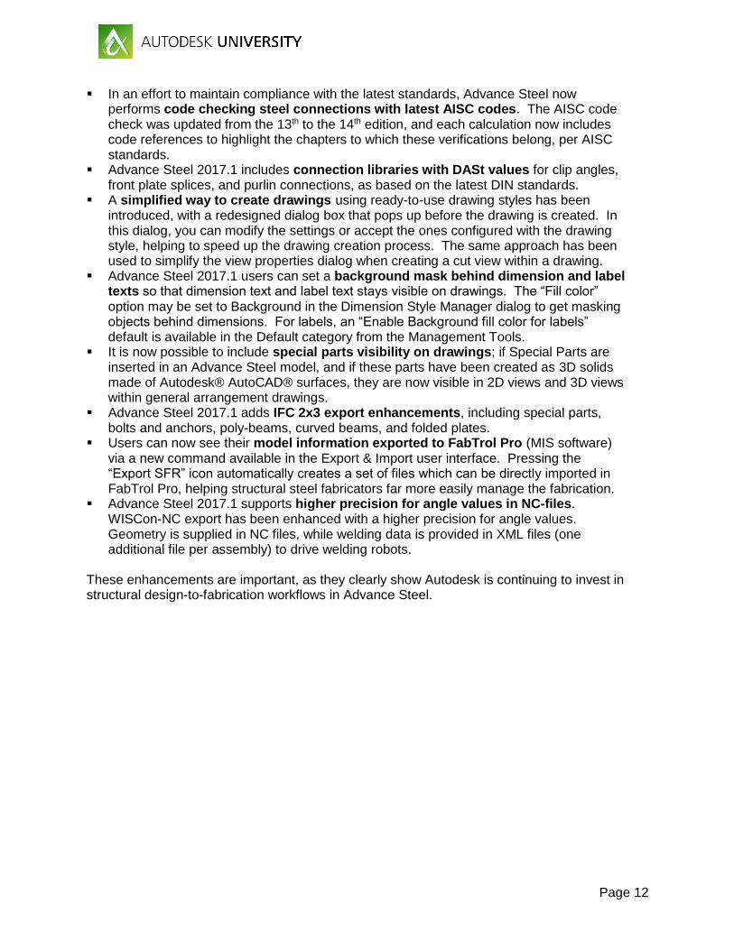
Autodesk® Robot™ Structural Analysis Professional (RSA) finite element analysis software helps engineers more quickly perform simulation, analysis, and code-based design for any type of structure. Fig. 12 highlights some of the key features of this product.
Figure 12: Key features of Robot Structural Analysis Professional 2017
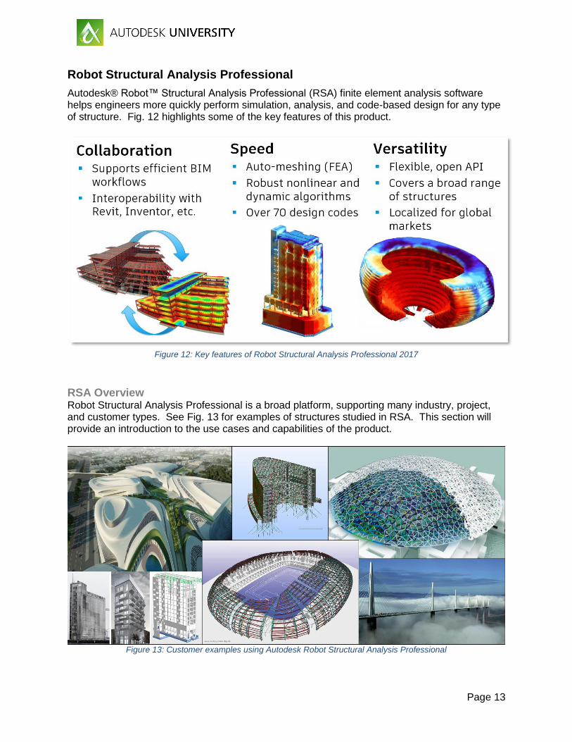
RSA Overview Robot Structural Analysis Professional is a broad platform, supporting many industry, project, and customer types. See Fig. 13 for examples of structures studied in RSA. This section will provide an introduction to the use cases and capabilities of the product.
Figure 13: Customer examples using Autodesk Robot Structural Analysis Professional
Page 14
Typical Customers RSA is used by customers across multiple industries, such as:
Structural engineers Multidisciplinary engineering teams Building product manufacturers and fabricators Large industrial machinery providers Oil and gas companies Mining firms
Design Versatility RSA is capable of analyzing concrete, steel, and timber designs.
Modeling Flexibility RSA handles many different types of structures, including:
2D and 3D frames and trusses Plates Shells Grillages Plane stress structures Plane deformation structures Axisymmetric structures Volumetric structures Composite beams
Advanced Analytical Capabilities RSA offers significant computational power, including:
Advanced finite element auto-meshing capabilities. A wide range of analysis capabilities, including linear and true nonlinear
behavior of any structure: Compression / tension elements Cable elements Non-linear constraints Material plasticity Non-linear hinges 2nd-order effects (non-linear) 3rd-order effects (P-delta)
State of the art dynamic solvers handle almost any size of structure efficiently, taking full advantage of multithreading. These include a full complement of dynamic analysis types: Modal Seismic Spectral Harmonic and FRF Time history (linear and non-linear) Elasto-plastic Pushover Footfall
Page 15
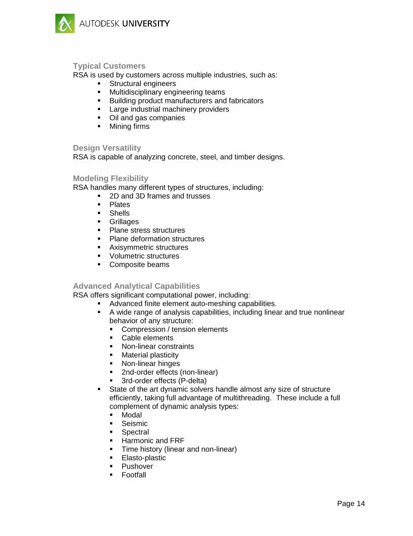
Wind Load Simulation Unique to RSA is the ability to simulate wind flow around a structure, generating wind loads automatically. This feature is especially useful for structures having a complex geometry, where it is difficult to define appropriate wind loads. The wind simulation feature acts as a wind tunnel and displays colored pressure maps on the model to assist with visualizing and understanding the effects of the wind, as shown in Fig. 14.
Figure 14: Wind load simulation in Robot Structural Analysis Professional
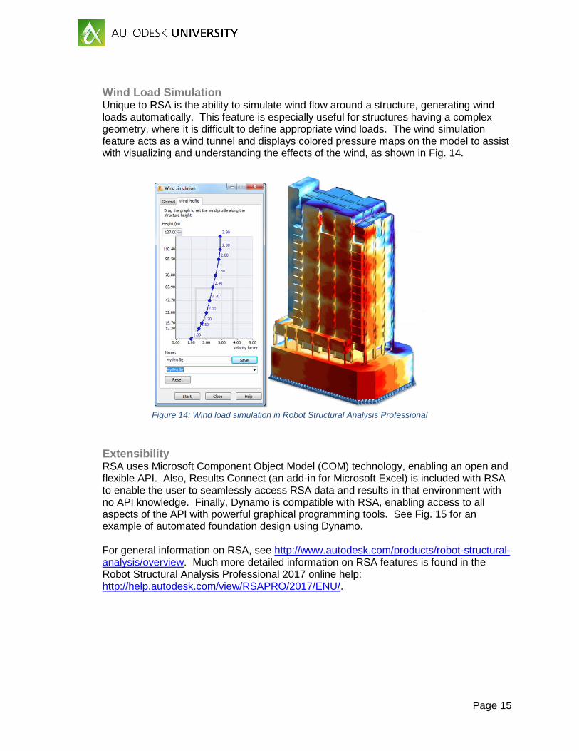
Extensibility RSA uses Microsoft Component Object Model (COM) technology, enabling an open and flexible API. Also, Results Connect (an add-in for Microsoft Excel) is included with RSA to enable the user to seamlessly access RSA data and results in that environment with no API knowledge. Finally, Dynamo is compatible with RSA, enabling access to all aspects of the API with powerful graphical programming tools. See Fig. 15 for an example of automated foundation design using Dynamo. For general information on RSA, see http://www.autodesk.com/products/robot-structural-analysis/overview. Much more detailed information on RSA features is found in the Robot Structural Analysis Professional 2017 online help: http://help.autodesk.com/view/RSAPRO/2017/ENU/.
Page 16
Figure 15: Dynamo-driven rebar creation in Revit, analyzable by RSA; image courtesy ABT
New Features and Enhancements As we saw with Revit, RSA also sees significant, ongoing development. Let’s take a brief look at the new features in RSA 2017: First, there have been some modifications to the steel section databases supported
by RSA; American ASTM A6 Jumbo sections (rectangular and square HSS, wide flange W, equal leg angles) have been added to the AISC database, and wide flange Super Jumbo sections (produced by ArcelorMittal) have been added to the ARCLRpro database. The Australian section database has also been adjusted such that the steel section names match the AS/NZS 1100.501 Technical Drawing code.
Section definition improvements include the ability to rotate a section’s coordinate system by 90 degrees (to achieve Iy > Iz), while disregarding the relationship between Iy and Iz, enabling constant orientation of a member’s local axis.
Changes to 2D Eurocode wind loads include taking into account the presence of a dominant wall (point 7.2.9.(5), EN 1991-1-4:2005), as well as the updating of external pressure coefficients for duo-pitch roofs (table 7.4a, NF EN 1991-1-4/NA/A1:2011-07).
In accordance with the Eurocode 8, the new Norwegian seismic analysis provisions (NS-EN 1998-1:2004+NA:2014) have been implemented.
New options for bar/slab reinforcement are available; transversal bar reinforcement density can now be presented graphically in RSA and exported to Revit. Diagrams may be displayed for all bars for which required reinforcement has been calculated; this information may be transferred to and displayed in Revit. Additionally, reinforcement zones, directions, descriptions, and other elements displayed on the provided reinforcement maps (meshes, panels, values, etc.) may now be saved as DWG/DXF files for use in other Autodesk software.
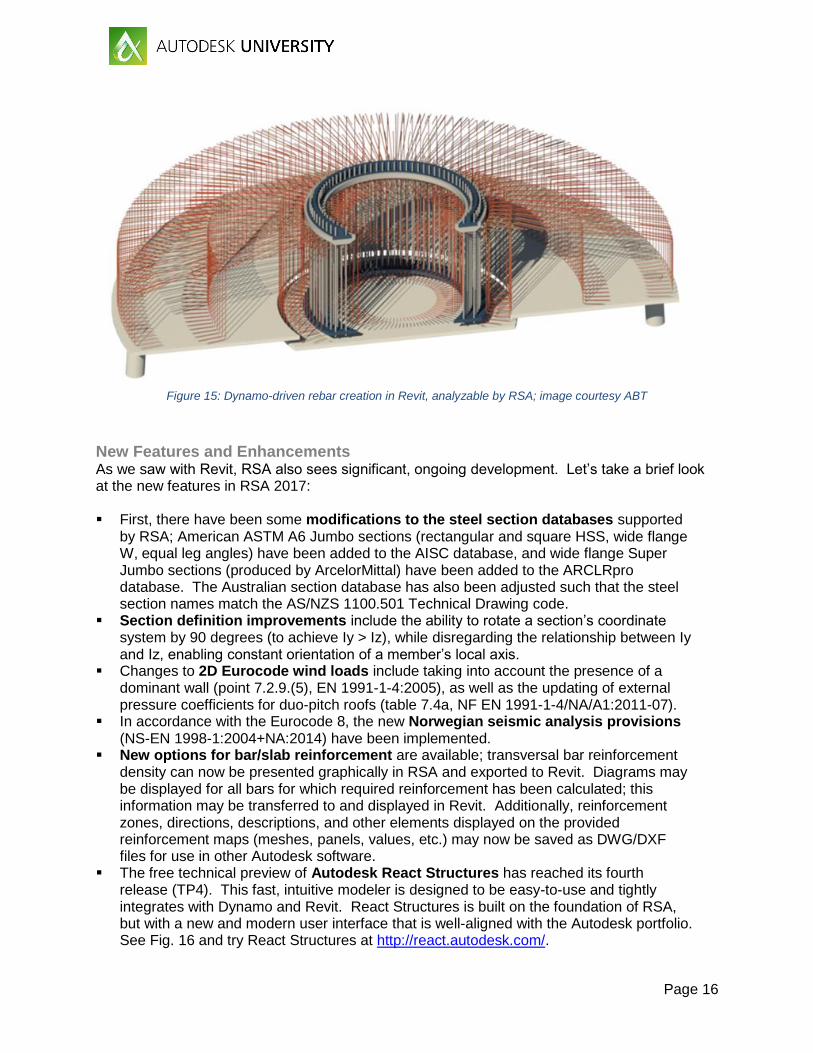
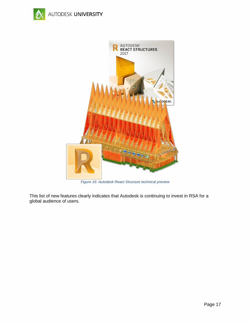
The free technical preview of Autodesk React Structures has reached its fourth release (TP4). This fast, intuitive modeler is designed to be easy-to-use and tightly integrates with Dynamo and Revit. React Structures is built on the foundation of RSA, but with a new and modern user interface that is well-aligned with the Autodesk portfolio. See Fig. 16 and try React Structures at http://react.autodesk.com/.
Page 17
Figure 16: Autodesk React Structure technical preview
This list of new features clearly indicates that Autodesk is continuing to invest in RSA for a global audience of users.
Page 18
Business Value
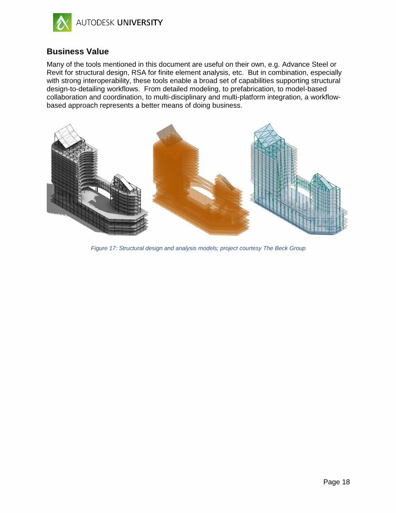
Many of the tools mentioned in this document are useful on their own, e.g. Advance Steel or Revit for structural design, RSA for finite element analysis, etc. But in combination, especially with strong interoperability, these tools enable a broad set of capabilities supporting structural design-to-detailing workflows. From detailed modeling, to prefabrication, to model-based collaboration and coordination, to multi-disciplinary and multi-platform integration, a workflow-based approach represents a better means of doing business.
Figure 17: Structural design and analysis models; project courtesy The Beck Group