esa broch envisat 2.xpr ir 36 - esa earth observation data · pdf filehuman race at the start...
TRANSCRIPT

ENVISAT-1 Mission & System Summary
EN
VIS
AT-
1 M
issi
on
& S
yste
m S
um
ma
ryIs
sue
2

Table of contents
Introduction 3
Mission 4
System 8
Satellite 16
Payload Instruments 26
Products & Simulations 62
FOS 66
PDS 68
Overall Development and Verification Programme 74
Industrial Organization 78
Tabl
e of
con
tent
s
1

Introduction
The impacts of mankind’s activities on the Earth’senvironment is one of the major challenges facing thehuman race at the start of the third millennium.
The ecological consequences of human activities is ofmajor concern, affecting all parts of the globe. Withinless than a century, induced climate changes may be bigger than what those faced by humanity overthe last 10000 years. The ‘greenhouse effect’, acid rain, the hole in the ozone layer, the systematic destruction of forests are all triggering passionate debates.
This new awareness of the environmental and climaticchanges that may be affecting our entire planet hasconsiderably increased scientific and political awarenessof the need to analyse and understand the complexinteractions between the Earth’s atmosphere, oceans,polar and land surfaces.
The perspective being able to make global observationsby satellite of the Earth has fostered the development ofa number of space-based remote sensing techniques.With its two satellites, has played a key role inthe development of these techniques for a wide range ofscientific and application oriented observations.
In 1988, an overall ‘Strategy for Earth Observation’was presented to the member states. This proposed a series of complementary polar-orbiting andgeostationary satellites to study the Earth’s environmentand resources, to continue and improve meteorologicalobservations.
Based on this scenario, two councils at ministeriallevel, held in Munich in November 1991 and Granadain November 1992, established a programme composedof two missions: the -1 mission and the -1mission preparatory programme.
While -1 is primarily an operationalmeteorological satellite, -1 is a satellite dedicatedto the study of the Earth and its environment.
With its launch planned for the end of the decade,-1 is a multidisciplinary mission having scienceand application objectives, continuing and extending the-1/2 mission objectives and contributing to acoherent European Earth Observation Programme.
The -1 mission constists of three main elements:
• the Polar Platform ();
• the -1 Payload;
• the -1 Ground Segment.
The development was initiated in 1989 as a multimission platform; the -1 payloadcomplement was approved in 1992 with the finaldecision concerning the industrial consortium beingtaken in March 1994. The -1 Ground Conceptwas approved in September 1994.
These decisions resulted in three parallel industrialdevelopments, together producing the overall -1system.
The development, integration and test of the variouselements are proceeding leading to a launch of the-1 satellite planned for the end of this decade.The satellite is designed for an in-orbit mission lifetimeof 5 years.
This document provides a brief description of the-1 mission objectives and the underlying systemdesign concept including all its major constituents andits relation to the operation strategy. It also describes thestatus of the design and development of the systemelements.
Intr
oduc
tion
3

4 Mission
To monitor and study our environment at global scale,polar orbiting remote sensing satellites offer uniquefeatures:
• complete Earth coverage;
• high revisiting rate;
• continuity of measurements over the seasons and years;
• stability and highly repeatible measurements.
However, due to the limited lifetime (a few years) ofeach satellite, the continuity of the measurements, whichis of paramount importance to monitor the evolution ofour environment and potential climate change, can onlybe ensured by flying a succession of polar orbit satellitemissions.
In this context, the main objective of the -1programme is to endow Europe with an enhancedcapability for the remote sensing of the Earth fromspace, with the aim of further increasing the capacity ofparticipating states to take part in the study andmonitoring of the Earth and its environment. Itsprimary objectives are:
• to provide for the continuity of the observations started with the satellites, including those obtained usingradar-based observations;
• to provide for the enhancement of the -1 mission, notably its ocean and ice missions;
• to extend the range of parameters observed to meet the need to increase knowledge of the factorsdetermining the environment;
• to make a significant contribution to environmental studies, notably in the areas of atmospheric chemistryand ocean studies (including marine biology);
coupled with two linked secondary objectives:
• to allow more effective monitoring and management of the Earth’s resources;
• to better understand solid Earth processes.
Mis
sion
These objectives will be achieved by developing:
• a package of instruments aimed at meeting the need to observe the Earth and its atmosphere from space in a synergetic fashion, addressing such matters as globalwarming, climate change, ozone depletion and oceanand ice monitoring;
• a ground segment including a flight operations segment, dedicated to spacecraft and mission control andoperations; a payload data segment, ensuring payloadoperations planning, data acquisition and processing,data distribution and archiving, and user services; takinginto account the existing ground infrastructure andthose of participating states.
The mission is intended to continue and improve uponmeasurements initiated by -1 and -2, and takinginto account the requirements related to the global studyand monitoring of the Earth and its environment asexpressed by international cooperative programmes suchas the International Geosphere and BiosphereProgramme and the World Climate ResearchProgramme. The mission is an essential element inensuring the long term provision of continuous datasets, essential for addressing environmental andclimatological issues. The mission will at the same timefurther promote the gradual transfer of applications ofremote sensing data from experimental to pre-operational and operational exploitation.

Mis
sion
5
AS
AR
GO
MO
S
RA
-2
ME
RIS
MIP
AS
MW
R
LR SC
IAM
AC
HY
DO
RIS
AA
TS
R
Instruments
Disciplines (Parameters)
CloudsHumidity
Radiative FluxesTemperatureTrace Gases
Aerosols
Atmosphere
Land
Surface TemperatureVegetation CharacteristicsSurface Elevation
Ocean
Ocean ColourSea Surface TemperatureSurface Topography
TurbidityWave Characteristics
Marine Geoid
Ice
ExtentSnow CoverTopographyTemperature
Part of the payload is focussed on ensuring thecontinuity of the -1/2 missions: , , ,-2 with its supporting instrumentation (, and ).
The observation of the ocean and coastal waters is theprimary objective of the instrument.
The ability to observe the atmosphere, following onfrom the instrument on -2, is significantlyenhanced by 3 instruments on -1 which offercomplementary measurement capabilitites:
• observation of a large quantity of atmospheric species by analysis of the absorption lines through theatmosphere;
• characterisation of the atmospheric layers as well as total column content by complementary limb and nadirobservations.
These instruments operate over a wide range of the electromagnetic spectrum, from centimetre waves toultraviolet.
The -1 mission includes both global andregional mission objectives with the corresponding needto provide data to both scientific and application users.
Instrument Contributions to -1
Mission Objectives
The -1 satellite comprises a set of developedinstruments (’s) complemented by Announcement ofOpportunity Instruments (’s) embarked on the PolarPlatform:
ESA Developed Instruments (EDI’s)MERIS
(Medium Resolution Imaging Spectrometer)MIPAS
(Michelson Interferometric Passive Atmospheric Sounder)ASAR
(Advanced Synthetic Aperture Radar)GOMOS
(Global Ozone Monitoring by Occultation of Stars)RA2
(Radar Altimeter 2)MWR
(Microwave Radiometer)LRR
(Laser Retro Reflector)
Announcement of Opportunity Instruments(AOI’s)
SCIAMACHY(Scanning Imaging Absorption Spectrometer for AtmosphericChartography)
AATSR(Advanced Along Track Scanning Radiometer)
DORIS (Doppler Orbitography and Radiopositioning Integrated by Satellite)

rug
10 mm 1 mm 10 cm 1 cm
1000
100
10
1
0.1
0.01107 108 109 1010 1011
H2O
O2H2O
O2
Ionosphere
HF VHF microwaves milimetre-waves
P L S C X K
Frequency (Hz
Wavelength
ASARGOMOSMERISMIPASMWRRA-2LR
AATSR DORISSCIAMACHY
Global RequirementsContinuous and coherent global data sets are needed by the scientific and application community to betterunderstand climatic processes and to improve climatemodels. Some of the global objectives require products availablein an off-line mode (days to weeks from sensing). Specific examples include quantitative monitoring of:
• radiative processes
• ocean-atmosphere heat and momentum exchange
• interaction between atmosphere and land or ice surfaces
• composition of the atmosphere and associated chemical processes
• ocean dynamics and variability
• ice sheet characteristics and sea-ice distribution and dynamics
• large scale vegetation processes in correlation with surface energy and water distribution
• primary productivity of oceans
• natural and man-made pollution over the oceans
as well as support to large international scientificprogrammes (, , , , etc.).
However, some global applications require near-real timedata delivery (from a few hours to one day fromsensing). Specific examples include:
• forecasting of sea state conditions at various scales
• monitoring of sea surface temperature
• monitoring of some atmospheric species (e.g. ozone for warning purposes)
• monitoring of some atmospheric variables (e.g. temperature, pressure and water vapour, cloud topheight, earth radiation budget, etc.)
• monitoring of ocean colour for supporting fisheries and pollution monitoring (complementing the regionalmission).
Regional RequirementsRegional data sets are needed by the scientific andapplication user community for a variety of objectives such as:
• sea ice tactical and strategic off-shore applications
• snow and ice detection and mapping
• coastal processes and pollution monitoring
• ship traffic monitoring
• agriculture and forestry monitoring (including tropical zones)
• soil moisture monitoring and large scale vegetation processes
• geological features and mineral resources
• applications linked to interferometry ( generation, hazard monitoring, etc.)
• hydrological research and applications
• support to fisheries in coastal waters.
Some of the regional objectives (e.g. sea ice applications,marine pollution, maritime traffic, hazard monitoring,etc.) require near real time data products (within a fewhours from sensing) generated according to userrequests. Some of the other objectives (e.g. agriculture,soil moisture, etc.) require fast turnaround data services(a few days). The remainder would be satisfied with off-line (few weeks) data delivery.
Mis
sion
6
Measurement Spectrum of -1
Instruments

Tit
el h
oofd
stuk
7
rug
10 cm 1 mm 0.1 mm 10 µm1 cm 1 µm 100 nm
109 1010 1011 1012 1013 1014 1015 1016 f (Hz)
H2O
O2
H2O
H2O
H2O
H2O
H2OO2
CO2
CO2
CO2
O3O3
O3
es milimetre-waves sub-milimetrewaves infra-red visible ultra-violet
S C X K
Frequency (Hz) 1015 1014 1013 1012 1011 1010 109
BandKa K Ku X C S L
AO
ES
A
Wavelength 0,1 µm 1 µm 10 µm 100 µm 0,1 cm 1 cm 10 cm 100 cm
Ultraviolet Microwave
ASARGOMOSMERISMIPASMWRRA-2LR
AATSR DORISSCIAMACHY
Infrared

Syst
em
System
AATSR
SCIAMACHY
MWR
Ka-band Antenna
DORIS
X-band Antenna
ASAR Antenna
MIPAS
MERIS
GOMOS
RA-2 Antenna
LRR
The system needed to achieve the -1 missionobjectives consists of two main building blocks:
• the Satellite
• the Ground Segment.
Furthermore, it will also utilise the Data RelaySatellite for instrument data recovery to complement the-1 direct to ground X-band links.
The satellite will be launched from the Kourou SpaceCentre in French Guyana by an Ariane 5 launch vehicle.
The -1 Satellite is composed of the payloadcomplement embarked on the Polar Platform.
The Payload comprises a set of seven DevelopedInstruments (’s), complemented by threeAnnouncement of Opportunity Instruments (’s),listed earlier.
The Polar Platform is constituted of two majorassemblies
• the Service Module () which accommodates most of the satellite support subsystems such as
- power generation, storage and distribution,- Attitude and Orbit Control System (),- communication on S-band,- support structure and launcher interface,
• the Payload Module () carrying the instruments and the payload dedicated support subsystems
- instrument control and data handling,- communication on X- and Ka-band,- power distribution,- support structure.
8

Syst
em
To fulfil its mission objectives, the orbit selected for the-1 satellite is sun synchronous, with a meanaltitude of 800 km and a descending node mean localsolar time of 10:00 am.
This orbit will be maintained such to ensure that thedeviation of the actual ground track is kept within 1 kmof the reference orbit track and the mean local solar timeis maintained within 1 minute.
The maintenance of the orbit require two types ofmanoeuvres:
• along track fine orbit control manoeuvres which will not interrupt payload operation but will degradetemporarily pointing performance. The time intervalbetween these manoeuvres depends on the solar activity.It can be as small as one week in case of maximum solaractivity.
• orbit inclination control manoeuvres, which will be performed at intervals of a few months, and which willinterrupt payload operation. These manoeuvres will beperformed in eclipse to avoid optical sensors be forcedto view the sun directly.
The selected orbit provides a 35 day repeat cycle (as forthe -2 mission). This orbit also provides variouscoverage subcycles, building up orbit track grids with afixed longitudinal drift from one subcycle to the nextwhich are of direct relevance to the realisation of themission objectives. The one-day and three-day orbitsubcycles provide a global sampling of the Earth which,for the instruments contributing to the global mission,is well matched to the objective of data assimilation inglobal meteo or climate models. The 17 day subcycle isdirectly relevant to the radar altimeter. The 35 day cycleprovides a good repeat grid for the altimeter, buildingup the equivalent of two interleaved 17 day grids; it alsooffers potential coverage access, with the highresolution imaging mode, to any part of the world.Since the orbit track spacing varies with latitude (theorbit track spacing at 60º latitude is half of the equator one) the density of observations and/orthe revisiting rate is significantly higher at high latitudesthan at the equator.
9Orbit
Orbits per day
Repeat cycle (days)
Orbit period (min)
Mean local time at descending node
Inclination (deg.)
Orbit radius (km)
Orbit velocity (km/sec)
Mean altitude (km)
1411/35
35
100.59
10:00
98.55
7159.5
7.45
799.8
Day 1Day 2Day 3
Day 1 to 3Day 4 to 6

10
Satellite command and control will nominally beperformed using S-band via the Kiruna Ground Station.During Launch and Early Orbit Phase, the KirunaStation will be complemented by an stationnetwork providing coverage of critical events.
The comprises all those elements which are relatedto payload data acquisition, processing, archiving as wellas those concerning the user interfaces and services. The will thus provide:
• all payload data acquisition for the global mission
• all regional data acquisition performed by stations
• processing in Near Real Time and dissemination of Fast Delivery Products
• data archiving, processing and delivery of off-line products with support of Processing and ArchivingCentres (’s)
• interfaces with national and foreign stations acquiring regional data
• interfaces to the users from order handling to product delivery.
The centres and stations will be coordinated by the Payload Data Control Centre () located at Frascati (Italy). The will interface with the for all mission planning activities.The stations include a Payload Data HandlingStation (-) providing X-band data reception andlocated at Kiruna salmijarvi, a Payload Data handlingStation (-) located at and receiving via anUser Earth Terminal () the data relayed via in Ka-band, a Payload Data Acquisition Station ()receiving X-band data and located in Fucino (Italy).
The Ground Segment will provide the means andresources to manage and control the mission, to receiveand process the data produced by the instruments andto disseminate and archive the generated products.Furthermore, it will provide a single interface to theusers to allow optimum utilization of the systemresources in line with user needs.
The Ground Segment can be split into two majorelements;
• the Flight Operation Segment () and
• the Payload Data Segment ().
The is composed of the Flight Operations ControlCentre (), located at Darmstadt (Germany),and the associated command and control stations. Itprovides control of the satellite through all missionphases:
• satellite operation planning based upon the observation plans prepared at the
• mission planning interface with
• command and control of the satellite, up-loading of operation schedules on a daily basis via the station at Kiruna-Salmijarvi (north Sweden).
Furthermore the will support:
• satellite configuration and performance monitoring
• software maintenance for and payload elements
• orbit prediction, restitution and maintenance.
Syst
em
Ka-band
S-band
ARTEMIS
User
PayloadDataSegment
FlightOperationsSegment
X-bandKa-band

Syst
em
11
The Instrument Data Transmission SystemThe satellite offers a programming capability whichpermits the operation schedule to be uplinked on a dailybasis. The instrument scheduling is directly derived fromthe global and regional mission objectives.
All instruments contributing to the global missiondeliver data at rates compatible with the on-board taperecorder capability. These low data rate instruments addup to a composite date rate of 4.6 Mbit/s. Use of on-board tape recorders, having each a capacity of 30 Gbits,allows full orbit recording. Therefore, for the low rateglobal data, the nominal strategy is to perform one tapedump per orbit via either the link (with datareception at the of ) or a direct X-band linkwith data reception at Kiruna. In both cases, the tapedump is performed at 50 Mbit/s and completed in lessthan 10 minutes. This strategy will permit thedistribution to users of global Near Real Time ()products within less than 3 hours of observation.
The regional mission includes the imaging modes of the (single swath or Scansar wide swath), and , inits 250 m Full Resolution mode. high rateoperation will be possible up to 30 minutes per orbit. operation is constrained, by the required solarillumination of the observed scene, to maximum 43 minutes per orbit.
Operation of the imaging modes of induces a datarate of 100 Mbit/s. Operation of Full Resolution,multiplexed with the low rate instruments real timetelemetry, induces a data rate of 50 Mbit/s. These data,acquired on a regional basis, can be either recorded on-board using the Solid State Recorder (), offering atotal capacity of 60 Gbits, or transmitted directly via theX-band and/or Ka-band data down links
The -1 satellite is capable of transmitting twodata streams at 100 Mbit/s each. Each 100 Mbit/s datastreams occupies a full X-band or Ka-band radiofrequency channel. Full Resolution real time datatransmission can be performed in parallel with on-boardrecorder tape dump using one single down link channelat 100 Mbit/s. The data can be down linked ateither 50 Mbit/s or 100 Mbit/s
The satellite is capable of providing simultaneousoperation of the X-band and Ka-band channels. For theregional mission, the simultaneous operation of the X-band and Ka-band channels may also be of interest topermit data acquisition by an X-band regional station inparallel with Ka-band operation via andreception at the .
Mission Operation & Data Recovery scenarii
Mission PlanningThe planning of the two missions will be performedaccordingly:
• The Global mission operation is provided in a Reference Operation Plan () which defines an operationstrategy valid for several months in advance, includingthe data recording segments on an orbit basis and thecorresponding tape dump sequence via orKiruna direct link.
• The Regional mission is mainly driven by the user requests received via the User Services. A complementary background observation plan can be defined in the .
Whenever a request for regional mission operation isrequested, the mission management control system willplan both the corresponding instrument operation andthe corresponding data recovery (direct data down linkor on-board data recording with deferred playback). Thestrategy selected for data recovery will take into accountthe location of the observation, the location of the userand the type of service requested. This could imply, inparticular cases, direct X-band data transmission invisibility of a national or foreign station, having anagreement with for the reception of the data, inparellel with data recovery by via on-board recordingor direct Ka-band data transmission.

12
Syst
em
SvallbardKiruna
Fucino
Station visibility masks and Artemis coverage
Mission ScenariiVarious scenarii have been defined and analysed forrecovery of the Global Mission:
• The nominal scenario is based on equal workloadsharing between the Kiruna station and the . Both Payload Data Handling Stations (- and -) will receive daily a sequence of about sevenconsecutive orbits. All received data will besystematically processed in Near Real Time () andthe corresponding products disseminated to the users.
• In case of temporary unavailability of the link, the Kiruna station will receive up to 10 consecutiveorbits per day. The remaining data, up to 5 orbits out of any Kiruna visibility, will be recorded on-board usingthe four recorders in cascade (3 tape recorders and the). The data will be dumped (in deferred time) withinless than a day, using the Fucino station. Thecorresponding data will be further routed and processedat the -. So, the service will not be providedfor four of these orbits per day.
• In case of permanent unavailability of , a high latitude X-band receiving station, in Svalbard,will be equipped with processing equipment,removed from the -, to complement Kiruna andrestore the nominal service to the users for all the orbits, the Svalbard station acquiring and processingall orbits out of Kiruna visibility.
For the regional mission, the nominal scenario is todownlink the data in X-band to the two stations ofKiruna and Fucino for data reception within theircoverage (european coverage). Data outside this coveragewill be acquired using the ssr or via the link,within coverage limit. Direct X-band down linkwill be planned when requested by duly authorisednational or foreign stations. In case of unavailibility, the Regional Mission direct data recoverywill be limited to the zones under coverage of ,national or foreign stations. Outside these directcoverage zones, data will be recorded on-board anddumped under X-band station coverage.
Ascending passes within Artemis visibility
Descending passes within Artemis visibility
Descending and ascending passes within Artemis visibility

Syst
em
13
The Instrument Derived Data Products
A comprehensive list of products has beenestablished and approved as part of the Ground Segmentconcept. This list includes the following type ofproducts:
• Level 0 products, time ordered Instrument Source Packets formatted as products;
• Level 1 products, geolocated engineering products;
• Level 2 products, geolocated geophysical products.
To ensure coherency of data product definitions andformatting through all the , as well as to define anapproach valid for both Near Real Time and Offlineproducts, the Agency has established precise productguidelines and organised a clear distinction between:
• the product definition and processing algorithm development assigned to a set of Expert Supportlaboratories (’s) and supporting industries;
• the Instrument Processor implementation assigned to the consortium and based on product andalgorithm detailed definition documents provided by the s and supporting industries.
This approach, coordinated by the Agency, has been sofar very successful:
• Commonality between and Offline algorithms has been confirmed, the product formats and processingalgorithms are identical, the main difference is in thequality of the auxiliary data available at processing time;
• The Instrument Processors being implemented in the are compatible with both and Offlineproduct generation.
• The same processors will be used in all centres and stations, ensuring constant product quality for users,coordinated upgrades and configuration controlthroughout the operation lifetime of the mission.
The User Services
The main objective of the -1 System is toprovide the required products to the users. The will provide, via its User Services accessible onInternet, an interface to the user community, registeringdata requests and organising the acquisition, processingand delivery of the corresponding products.
The ground segment concept and architecture willprovide a unified service to the users with access, oncethe user is registered, to the full range of servicesprovided by the centres and stations offering services.
From the user’s point of view, the services offered willprovide:
• a decentralised system offering an homogeneous and consistent suite of services accessible via Internet in a transparent way (without the need to know where the data inventory nor the data are physically located);
• on line ordering of the products available and their delivery via electronic links or physical media accordingto size of product and network capabilities available;
• satellite links for systematic dissemination of global data and for on request dissemination of high resolution regional products;
• Offline product distribution on physical media;
• ordering of products implying satellite data acquisitions to be planned by the ;
• support of the Help Desk and Order Desk located at the .

14 System Coherence
The complex contractual and engineering environmentof the overall -1 system, with its threeindependent contracts, requires on the one hand anunambiguous and comprehensive definition of the splitof responsibilities between the various parties involvedand on the other hand close cooperation between theseparties to ensure the well coordinated coherentdevelopment of an homogeneous system fulfilling thesystem requirements.
With respect to the and -1 Mission/Systemprogrammes this cooperation is well established in allareas relevant to the programme.
The baseline for the cooperation is recorded in a set ofdocuments defining the split of managerial and technicalresponsibilities as well as providing a clear technicalbaseline for the interfaces between the payloadinstruments and the :
• / -1 Contractor Mutual Responsibility Definition (MuReD),
• -1 Reference Accommodation,
• Payload Applicability Matrix to the for -1,
• Mission Specific Annexes to Support Specifications,
• Avionics Interface Specification,
• Common Interface Control Document (),
• Instrument Specific Interface Control Documents (’s), one per instrument,
• to ,
• Satellite Reference Database to Payload Macrocommand and Telemetry Data Definition Database .
All these documents have been agreed between theAgency and the two Prime Contractors (Dornier and-) as well as, where applicable, with the InstrumentContractors.
Concerning the interface between the satellite and theGround Segment, a clear document baseline isestablished:
• Satellite to / ,
• Payload to / ,
• Mission Prime Assumptions on /
• Flight Operation Manuals for the and all payload elements.
• Satellite Reference Database (telecommand and telemetry) for the and all payload elements.
The Interface of the -1 satellite and groundSegment with is established:
• Interface Control Document Between The Data Relay System and the -1 System.The interface with 5 is controlled via the:
• Launch System/Spacecraft Interface control File
Numerous Ground Segment documents have beenestablished to control the interfaces, in particular:
• to interface;
• to provider interfaces;
• to provider interfaces;
• to (-1 Mission Management Interface including Reference Operation Plan andInstrument Calibration tables)
The transfer of information from the s (products andalgorithm definition) to the consortium is governedby two documents for each instrument:
• The (Input Output Detailed Definition)
• The (Data Processing Model).
Preparation of the Commissioning Phase, including theinstrument in-orbit calibration and the level 2 productvalidation, is the responsibilty of the Project Team.
The overall -1 system coherency remains theresponsibility of the Agency via its Project Team. A System Overall Verification Plan has been establishedto ensure that all requirements, as specified in theMission requirements Document, are properly verified.A Ground Segment Overall Verification is planned to beperformed prior to the Ground Segment ReadinessReview. Verification of all -1 Ground Segmentexternal interfaces will be performed, including theSatellite, the interfaces between all the Ground segmentelements as well as the capability of the total GroundSegment to support a sustained operation test.
Syst
em
24800

Syst
em
15
24800
10000
8000
11500
Launch mass
Payload mass
Solar array power (EOL)
Instruments
ENVISAT-1
8140 kg
2145 kg
6500 W(After 4 years)
10
ERS-2
2510 kg
710 kg
1940 W(After 3 years)
5
Comparison

16
-1 will be the largest free flying satellite built inEurope. Ten instruments, accommodated on the PolarPlatform, compose its payload.
Sate
llite
Satellite Overall Configuration
The major driver for the -1 satelliteconfiguration has been the need to maximise thepayload instrument mounting area and to meet viewingrequirements whilst staying within the constraints of theAriane 5 fairing and interfaces.
The most demanding instrument in terms of mass,volume and power resources is the with an antennaof circa 700 kg but 6 other large instruments also sharethe satellite resources with mass ranging between 100 kgand more than 300 kg.
In addition, the configuration has been driven by the re-use of the Mk II Service Module design conceptand payload accommodation experience.
This configuration concept provides a large, modularconstruction, with sufficient Earth facing mountingsurface for payload instruments and an anti-sun face,free of occultation by satellite subsystem equipment. In-flight, the spacecraft longitudinal axis (the X-axis) isnormal to the orbit plane, the Y-axis is closely aligned to the velocity vector and the Z-axis is Earth pointing.
The satellite comprises two major assemblies:
• The Service Module () which provides the main satellite support functions
• The Payload Module () on which the payload instruments are mounted
The Payload Module itself is composed of three majorsubassemblies:
• The instruments either externally mounted or partly accommodated in the Polar Platform
• The Payload Equipment Bay () which accommodates payload support subsystems and someinstrument electronics
• The Payload Carrier () which provides the main structural support for externally mounted instrumentsand antennas.
This split provides the basis for a convenient physicaland functional separation between the Service Modulesubsystems and equipment which is needed for everymission and those in the Payload Module which aremission specific and therefore dedicated only to theneeds of the particular payload complement beingflown. In addition, the interface, decoupling at modulelevel, facilitates parallel development and integration ofService and Payload Modules and allows for an efficientsatellite programme where only a minimum ofsystem level activity is needed for final verification.
yz
x
/-1
Satellite Launch and Inflight
Configuration

Sate
llite
17
Star Sensors
Payload Carrier
DRS Antenna
Payload Equipment Bay(Payload Support Equipment & InstrumentElectronics inside PEB)
Propulsion assembly
Service Module
Solar Array (deployed)
PPF/ENVISAT-1 Functional Split
PPF / ENVISAT-1 Satellite
Payload Module PLM
Service Module SM
Payload Carrier PLC
Payload Equipment PEBBay
ENVISAT-1 Instruments (externally mounted)- Instrument antennas (ASAR, RA-2)- MERIS, MIPAS, GOMOS optical assembly,
SCIAMACHY, MMR, DORIS
Support subsystems- Mechanical support to instruments and PEB Equipment- PLM interface with the SM- Mechanical support for AOCS sensors and thrusters
ENVISAT-1 Instrument electronics (internally mounted)- ASAR, RA-2, GOMOS
Support subsystems- Payload data management and multiplexing- Payload data communications in X- and Ka-band- Power distribution for instruments- Thermal control for instruments- Electrical interface to instruments
- Launcher interface and Payload Module support- Power generation, storage and distribution- Attitude and orbit control- Telemetry, tracking and command- Monitoring and control of on-board operations

Design Description
The Service Module () developed by -, is basedon the concept and design of the Mk II ServiceModule with a number of important new developmentsparticularly in the area of mechanical design. Theseinclude:
• An enlarged Service Equipment Module consisting of a box shaped structure made in aluminium honeycombpanels fabricated around a central cone whichconstitutes the primary structure. The majority ofthe subsystem equipment, including additional actuators to cope with the increased size of -1compared to , are located inside this module. At the lower end of the module, the cone provides anincreased diameter of 2.6 m for interfacing with the 5 launch vehicle adaptor. The upper end of thecone provides the interface to the Propulsion Moduleand in turn the central cylinder.
• An enlarged Battery Compartment, which comprises the lower 600 mm of the central cone attached to analuminium alloy battery plate, allows installation of 8 batteries.
• A Propulsion Module, which comprises an aluminium alloy machined plate, interfaces to the central coneupper ring. This supports 4 propellant tanks which areattached to the plate through equatorial rings andprovide -1 with a fuel capacity of 300 kg ofhydrazine.
The attitude and orbit control, the reaction control, the power distribution and storage and data handlingsystems are extensively re-using developedhardware, either unmodified or with minormodification. In addition, the on-board and groundcheck-out softwares are re-used with only limitedmodification.
New developments have been carried out in several areas(Structure, Solar Array, S-band Transponder) where noexisting design was available to fulfil the requirements.The single wing Solar Array is a new development. The array comprises a primary deployment mechanismand arm plus a set of 14 deployable rigid panels. This array is based on the rigid panel technologydeveloped by and already flown on . In the launch configuration the array is stowed foldedagainst the zenith faces of the and . Once deployed the solar array is rotated to pointcontinuously towards the sun using a solar array drivemechanism which is attached to the base of the central cone. The Dual Mode Transponder is anothernew development compared to -4. It provides a 2000 bit/s forward and a 4096 bit/s returnS-band link capability. Ranging and range ratemeasurements are performed by ground stations on therange signals transmitted by the transponders in eithercoherent or non coherent modes.
The Payload Carrier () provides the main structuralsupport for the and the externally mountedinstruments and antennas. In addition the providesaccommodation for certain equipment which arefunctionally part of the Service Module but locatedon the . These are:
• star sensor optical assembly mounted on zenith face near the forward end of the to allow unobstructed fieldof view, star sensor electronics, located inside the upper section,
• gyro mechanical assemblies located close to the star sensor optical assembly to minimise misalignment.
• propulsion subsystem thrusters distributed on to provide equalisation of control torques and forces aboutthe satellite centre of mass.
Sate
llite
18
The Polar Platform ProtoFlight Service Module
during thermal tests in the Large Space
Simulator () View from the top.
Service Module is upside down with Battery
Compartment on top and visible on picture.

Sate
llite
19
MEGS
Batteries
Thruster AssemblyReaction Wheels
PropulsionAssembly
S-band Antenna
Stowed Solar Array
The Development Model of the Solar
Array (fully deployed configuration)
(Photo courtesy of Fokker)
Service Module Design Concept

20
The Payload Equipment Bay () provides all necessaryfunctions to support and control the payloadinstruments as well as all functions required to handlethe scientific data. The U-shaped configuration,consisting of the zenith and side panels of the lowerthree sections of the Payload Module (), houses thefollowing entities:
• The Payload Management Assembly comprising the Payload Management Computer () with its missionspecific application software, which controls andmonitors via three Remote Terminal Units (’s) all functions and via dedicated Digital Bus Units(’s) the payload instruments. The s and the sare connected by the On-Board Data Handling ()-Bus to the .
• The data handling subsystem including:- the High Speed Multiplexer (), which can select
and assemble the instrument data into a continuous datastream,
- four 30 Gbit tape recorders, allowing for intermediate storage of output data during periods withoutdirect ground station coverage, and
- the Encoding and Switching Unit (), to encode and switch hsm, tape recorder play-back or payload highrate data to different downlink channels.
• The X-band transmission subsystem, with three 100 Mbit/s links for direct transmission to ground,comprising the modulators, the Travelling Wave Tubes() and their power conditioners for signal
Sate
llite
amplification, the Output Multiplexer (), which combines the three links prior transmission, andthe fixed X-band antenna located on the PayloadModule Earth face.
• The Ka-band transmission subsystem, providing three 100 Mbit/s links for data transmission to ground via theAgency’s Satellite. It uses similar modulationand amplification hardware as the X-band subsystem,but requires on the zenith panel an outboard assemblyconsisting of a deployable mast carrying the AntennaPointing Mechanism (), which controls the antennapointing to the Data Relay Satellite according to adefined trajectory.
• The power subsystem, comprising two Power Distribution Units (’s), one for the and theother for the Instruments and the Heater SwitchingUnit () which provides switching to Payload Moduleheaters under control of the Payload ManagementComputer.
4.5 Mbit/s
4.5 Mbit/s
4.5 Mbit/s
4.5 Mbit/s
9 LBR1 MBRChannels
50 Mbit/s
50 Mbit/s
50 Mbit/s
50 or 100
Mbit/s
50 Mbit/s
100 Mbit/s
100 Mbit/s
HBRInstrumentChannel 2 x 50 Mbit/s
Antenna Mast
DeploymentJoint
Data
High Speed
Multiplexer
Tape
Recorder 1
Tape
Recorder 2
Tape
Recorder 3
Solid State
Recorder
Encoding
and
Switching
Unit
Modulator
1 / 2 / 3
Modulator
1 / 2 / 3
TWTA
1 / 2 / 3
TWTA
1 / 2 / 3
OMUX
XBS
Hold Down& ReleaseMechanism
MastDeploymentMechanism
APM
APC
OMT POL
KBS
PMD
SparePort
DBUPWR
DATA
RTU 3
toDMS
PMC 1
Dg I/O
RTU 2
toDMS
RTU 1
toDMS
I/F
HSUPDU 1 PDU 2
P/L OBDH Bus
OM
UX
SMOBDH-
toInstruments
Power I/F
Payload Equipment Bay Functional Block Diagram
Payload Equipment Bay Ka-band
Outboard Assembly Engineering Model
(Photo courtesy of Dornier)
Sate
llite
21
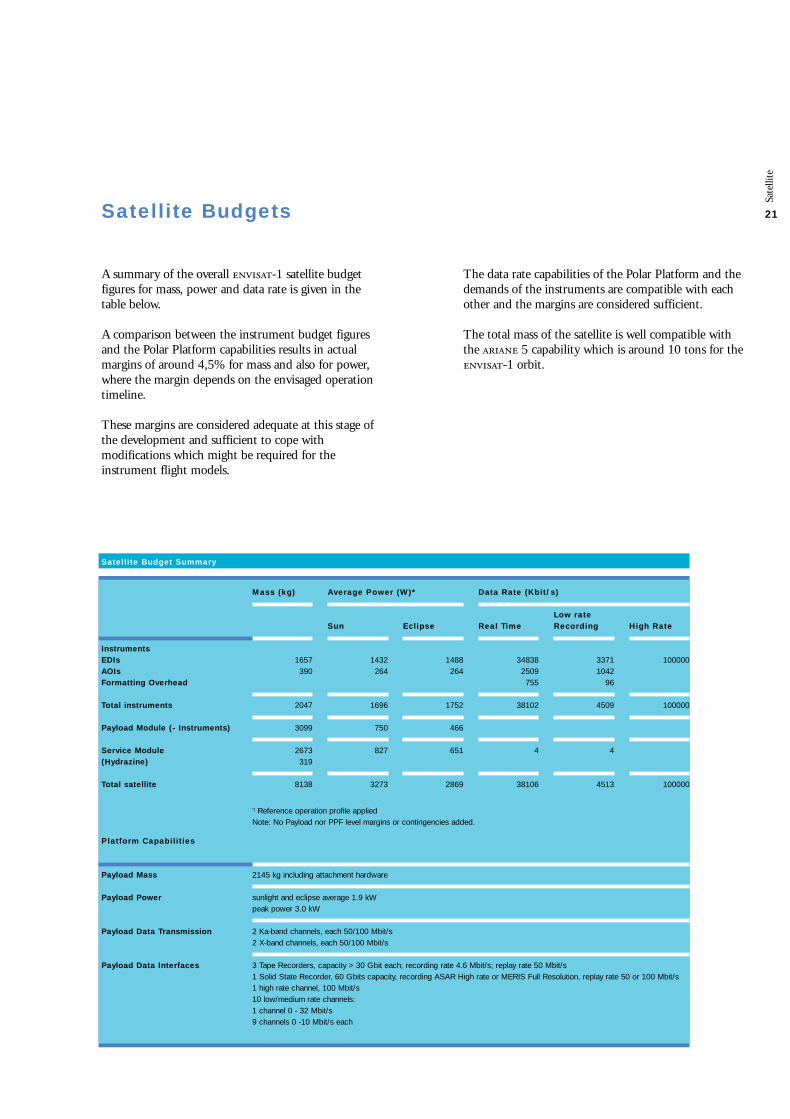
A summary of the overall -1 satellite budgetfigures for mass, power and data rate is given in thetable below.
A comparison between the instrument budget figuresand the Polar Platform capabilities results in actualmargins of around 4,5% for mass and also for power,where the margin depends on the envisaged operationtimeline.
These margins are considered adequate at this stage ofthe development and sufficient to cope withmodifications which might be required for theinstrument flight models.
Mass (kg) Average Power (W)* Data Rate (Kbit/s)
Satellite Budget Summary
Sun
1432264
1696
750
827
3273
Eclipse
1488264
1752
466
651
2869
Real Time
348382509755
38102
4
38106
Low rateRecording
33711042
96
4509
4
4513
High Rate
100000
100000
100000
1657390
2047
3099
2673319
8138
2145 kg including attachment hardware
sunlight and eclipse average 1.9 kWpeak power 3.0 kW
2 Ka-band channels, each 50/100 Mbit/s2 X-band channels, each 50/100 Mbit/s
3 Tape Recorders, capacity > 30 Gbit each; recording rate 4.6 Mbit/s; replay rate 50 Mbit/s1 Solid State Recorder, 60 Gbits capacity, recording ASAR High rate or MERIS Full Resolution, replay rate 50 or 100 Mbit/s1 high rate channel, 100 Mbit/s10 low/medium rate channels:1 channel 0 - 32 Mbit/s9 channels 0 -10 Mbit/s each
InstrumentsEDIsAOIsFormatting Overhead
Total instruments
Payload Module (- Instruments)
Service Module (Hydrazine)
Total satellite
Platform Capabilities
Payload Mass
Payload Power
Payload Data Transmission
Payload Data Interfaces
*) Reference operation profile appliedNote: No Payload nor PPF level margins or contingencies added.
The data rate capabilities of the Polar Platform and thedemands of the instruments are compatible with eachother and the margins are considered sufficient.
The total mass of the satellite is well compatible withthe 5 capability which is around 10 tons for the-1 orbit.
Satellite Budgets

22
The development of the Polar Platform is well advanced.Following the preliminary design phase completed byearly 1994 and reviewed by the Agency in the frame ofthe s Preliminary Design Review, held in mid 94, thedetailed design has been completed and themanufacturing of electronics units initiated.
During this phase, technology critical equipment andsubsystems have been the object of intensivedevelopment and breadboarding (ie. 1/3 scaled modelsolar array, Ka-band Antenna Pointing Mechanism, structural element, Tape Recorder, etc.).Furthermore, two satellite-level models (configurationmodel and mock-up) were used for the earlyverification of the design. An impressive set ofMechanical Ground Support Equipment (Transportcontainers, integration stands) have been developed aswell as basic Electrical Ground Support Equipment ableto control and operate the Service Module and PayloadModule.
Sate
llite
Polar Platform Development Status
Engineering Model of Polar Platform
Payload Module in integration at
() ( Integrated,
-2 in foreground)
(Photo courtesy of () )

Sate
llite
23
The manufacturing of the structure and structuralelements, started in 1994, was the basis for theStructural Model () Polar Platform which, afterassembly by (), was shipped to in April 96to perform the mechanical qualification tests. For some of the tests mechanically representative modelswere mounted on the Polar Platform ( antenna,, , and ). The mechanical test programme is now basicallycomplete with the completion of the vibration tests inJanuary / February 1997.
By mid 1996 the Engineering Model () of thePayload Electronics Bay () has been delivered by to () for integration into the EngineeringModel Payload Carrier to become the EngineeringModel () payload module. The integration of instruments engineering or reducedmodels has been already completed, allowing to proceedwith the satellite test programme.
The Flight Model () units of the have beenmanufactured and integrated into the Flight Modelin .
The Service Module () is a Proto-Flight Model asmost of its electronics units are re-used from the -4design. The flight units were manufactured in thetime frame end 1994 to mid 1996 and the integrationof this module has now been completed.
Interfaces with all the major elements have beenfinalised. This applies in particular to the launcher andthe system. Detailed interfaces with theinstruments which are internal to the satellite have beendefined and formalised.
From a contractual viewpoint, the Polar Platformdevelopment contract was signed by the Agency and in July 1995 while the 5 Launcher contractwas signed with in November 1996.
ARIANE 5 interface
The satellite will be launched on an 5launch vehicle and separated in-orbit about 24 minutesafter launch. The satellite is bolted to an interface ring,which itself provides the interface with the launchervehicle adaptor separation system.
The interfaces with the 5 launcher have beendetailed and agreed with , the launchauthorities. Preliminary definition of the launchactivities in Kourou has permitted problem areas to beexplored and the major optional services needed from defined.
ARTEMIS interfaces(inter-orbit link aspectonly)
The Satellite interfaces with have beenworked out in close coordination with the Project. In 1994, an Agency internal review (Inter OrbitLink Review) was held to review the definition and thestatus of the interfaces between the two satellites.All in-orbit and on-ground interfaces are well definedand no problem was encountered during this review.

24
Sate
llite
The development approach used in the European PolarPlatform program includes several measures intended toreduce development risks and costs:
• The platform comprises two major functional elements: the Service Module and the Payload Module. Theirphysical and functional autonomy allows them to bedeveloped, integrated, and tested in parallel.
• The payload instruments, which also have maximum functional autonomy from the polar platform, can bedeveloped and verified separately and integrated withthe platform relatively late in the assembly phase forfinal mechanical, electrical and functional checks.
• In view of the reuse of -4 equipment in the Service Module, most of its electrical units use designsthat have already been qualified. This allows thedevelopment of this module to be based on a protoflightapproach.
The model philosophy incorporates all these measures.Satellite qualification and acceptance will be achieved byusing three basic major satellite models: the StructuralModel (t), Engineering Model (), and the actualFlight Model ().
In addition, during the development phase, two satellitelevel models have been used: The Configuration Model,which is a full scale mock-up of the satellite,was used to study accommodation as well as access andcompatibility with major activities. The Mock-Up () spacecraft model is a hardware development tool used in support of the overall satellite analyses.
• The Structural Model Satellite consists of a fully representative structural model of the and structuralmodels for some of the instruments and mass dummiesfor others. Its objectives are to achieve mechanicalqualification of the structure, verification of mechanicalground support equipment and facility interfaces, and
verification of handling procedures.
• The Engineering Model Satellite consists of the Protoflight Service Module assembled with theEngineering Model Payload Module integrated withelectrically representative models of the instruments.The objectives are to verify the electrical design and tovalidate assembly integration and test procedures andaspects related to the satellite’s operation.
• The Flight Model Satellite comprises the protoflight Service Module and the flight model Payload Moduleequipped with the provided instruments. The Flight Model undergoes a complete flightacceptance program and is used for verification of thePayload Module’s thermal control system.
The -1
Structual Model during acoustic
testing in the
(Large European Acoustic Facility)
The Polar Platform and satellite development programme

Tit
el h
oofd
stuk
25
ENVISAT-1 Payload Characteristics
Instruments
ASAR
GOMOS
LR
MERIS
MIPAS
MWR
RA-2
AATSR
DORIS
SCIAMACHY
Total
Mass1)
(kg)
830
163
2
207
320
25
110
101
91
198
2047
Power1,2)
(W)
Image: 1365Wave: 647ECL: 839SUN: 751
146
-
ECL: 124SUN: 157
195
23
161
100
42
122
ECL: 1752SUN: 1696
Data Rate(Mbit/s)
Image: 100Wave: 0.9Global: 0.9
0.222
-
Full res.: 24.0Red. res.: 1.6
recorded: 0.53real time: 8.0
0.017
0.1
0.625
0.017
recorded: 0.4real time: 1.867
Duty Cycle
continuously,Image: 30 minGlobal monit.or wave: rest
continuously
Sun light(43 min.)
continuously
continuously
continuously
continuously
continuously
continuously
GeometricalResolution
Image: 30m x 30mWide Swath:
150m x 150mGlobal: 1 km x 1 km
1.7 kmvertical resolution
-
Full: 250 m x 250 mRed.: 1 km x 1 km
3 kmvertical resolution
20 kmspot beam diameter
1 km x 1 km
orbit: 10 m radial,25 m others
3 kmvertical resolution
Wavelength/Frequency Range
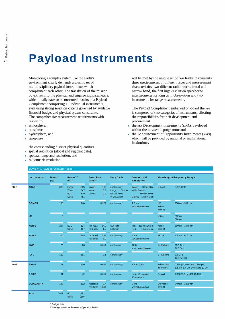
Monitoring a complex system like the Earth’senvironment clearly demands a specific set ofmultidisciplinary payload instruments whichcomplement each other. The translation of the missionobjectives into the physical and engineering parameters,which finally have to be measured, results in a PayloadComplement comprising 10 individual instruments,even using strong selection criteria governed by availablefinancial budget and physical system constraints. The comprehensive measurement requirements withrespect to
• atmosphere,
• biosphere,
• hydrosphere, and
• geosphere
the corresponding distinct physical quantities
• spatial resolution (global and regional data),
• spectral range and resolution, and
• radiometric resolution
will be met by the unique set of two Radar instruments,three spectrometers of different types and measurementcharacteristics, two different radiometers, broad andnarrow band, the first high-resolution spaceborneinterferometer for long term observation and twoinstruments for range measurements.
The Payload Complement embarked on-board the is composed of two categories of instruments reflectingthe responsibilities for their development andprocurement
• the Development Instruments (’s), developed within the -1 programme and
• the Announcement of Opportunity Instruments (’s) which will be provided by national or multinationalinstitutions.
Payl
oad
Inst
rum
ents
26 Payload Instruments
C-band
UV,visible,near IR
visible
visible,near IR
mid IR
K-, Ka-band
S-, Ku-band
visible, nearIR, mid IR
S-band
UV, visiblenear IR
5.331 GHz
250 nm ÷ 952 nm
532 nm694 nm
390 nm ÷ 1040 nm
4.2 µm ÷ 14.6 µm
23.8 GHz36.5 GHz
3.2 GHz13.575 GHz
0.555 µm; 0.67 µm; 0.865 µm; 1.6 µm; 3.7 µm; 10.85 µm; 12 µm
2.03625 GHz; 401.25 MHz
240 nm ÷ 2380 nm
1) Budget data2) Average Values for Reference Operation Profile
EDIS
AOIS
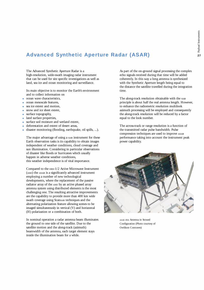
The Advanced Synthetic Aperture Radar is a high-resolution, wide-swath imaging radar instrumentthat can be used for site specific investigations as well asland, sea ice and ocean monitoring and surveillance.
Its main objective is to monitor the Earth’s environmentand to collect information on
• ocean wave characteristics,
• ocean mesoscale features,
• sea ice extent and motion,
• snow and ice sheet extent,
• surface topography,
• land surface properties,
• surface soil moisture and wetland extent,
• deforestation and extent of desert areas,
• disaster monitoring (flooding, earthquake, oil spills, ...).
The major advantage of using a instrument for theseEarth observation tasks is its capability to obtain imagesindependent of weather conditions, cloud coverage andsun illumination. Considering in particular observationsof disaster like floods or hurricanes which usuallyhappen in adverse weather conditions, this weather independence is of vital importance.
Compared to the -1/2 Active Microwave Instrument() the is a significantly advanced instrumentemploying a number of new technologicaldevelopments, where the replacement of the passiveradiator array of the by an active phased arrayantenna system using distributed elements is the mostchallenging one. The resulting attractive improvementsare the capability to provide more than 400 km wideswath coverage using Scan techniques and thealternating polarization feature allowing scenes to beimaged simultaneously in vertical (V) and horizontal(H) polarization or a combination of both.
In nominal operation a radar antenna beam illuminatesthe ground to one side of the satellite. Due to thesatellite motion and the along-track (azimuth)beamwidth of the antenna, each target element staysinside the illumination beam for a while.
As part of the on-ground signal processing the complexecho signals received during that time will be addedcoherently. In this way a long antenna is synthesizedwith the Synthetic Aperture length being equal to the distance the satellite travelled during the integrationtime.
The along-track resolution obtainable with the principle is about half the real antenna length. However,to enhance the radiometric resolution multilookazimuth processing will be employed and consequentlythe along-track resolution will be reduced by a factorequal to the look number.
The across-track or range resolution is a function of the transmitted radar pulse bandwidth. Pulsecompression techniques are used to improve performance taking into account the instrument peakpower capability.
Payl
oad
Inst
rum
ents
27Advanced Synthetic Aperture Radar (ASAR)
t Antenna in Stowed
Configuration (Photo courtesy of
Oerlikon Contraves)

405 km 485 km100 km
global monitoring wide swath
image alternating/cross polarization
wave
flight direction
28
Instrument Parameters
Image
VV or HH
≤ 30 m ≤ 30 m(~4 looks)
≤ 2.5 dB
up to 100 km
≥ 27 dB≥ 30 dB
≥ 23 dB≥ 13 dB
≤ 1.6 dB
≤ 100 Mbit/s
1365 W
Wide Swath
VV or HH
≤ 150 m ≤ 150 m(~12 looks)
≤ 2.0 dB
≥ 400 km
≥ 24 dB≥ 24 dB
≥ 22 dB≥ 13 dB
≤ 1.5 dB
≤ 100 Mbit/s
1200 W
Alternating/CrossPolarization
VV/HH, VV/VHor HH/HV
≤ 30 m ≤ 30 m(~2 looks)
≤ 3.6 dB
up to 100 km
≥ 21 dB≥ 25 dB
≥ 20 dB≥ 13 dB
≤ 2.0 dB
5.331 GHz
1650 to 2100 Hz
up to 16 MHz
10 m x 1.3 m
≤ 100 Mbit/s
830 kg
1395 W
Wave
VV or HH
≤ 10 m ≤ 10 m(single look)
≤ 2.3 dB
5 km vignette
≥ 27 dB≥ 30 dB
≥ 23 dB≥ 17 dB
≤ 2.2 dB
0.9 Mbit/s
647 W
GlobalMonitoring
VV or HH
≤ 1000 m ≤ 1000 m(>7 looks)
≤ 1.6 dB
≥ 400 km
≥ 26 dB≥ 24 dB
≥ 23 dB≥ 13 dB
≤ 1.8 dB
0.9 Mbit/s
713 W
Polarization
Spatial Resolutionalong-trackacross-track
Radiometric Resolution
Swath Width
Ambiguity Ratio (Point)along-trackacross-track
Ambiguity Ratio (Distrib.)along-trackacross-track
Radiometric Accuracy (36)
Centre Frequency
Pulse Repet. Frequ.
Chirp Bandwidth
Antenna Size
Operation
Data Rate
Mass
Power
*) except for one far swath
up to 30 min/orbit
Rest of orbit
485 km
wave
tion
Payl
oad
Inst
rum
ents
29
The instrument is designed to operate in the followingprincipal operating modes
• image,
• wide swath,
• alternating polarization mode,
• wave, and
• global monitoring.
In image mode the gathers data from relativelynarrow swaths (100 km within a viewing area of appr.485 km) with high spatial resolution (30 m), whereas inwide swath mode using techniques a muchwider stripe (≈400 km) is imaged with lower spatialresolution (150 m). The alternating/cross polarizationmode provides imaging in /, / and /polarization of the same scene with a spatial resolutionequal to image mode but reduced radiometricresolution. In wave mode, measures the change inradar backscatter from the sea surface due to oceansurface waves. In this mode images of 5 km x 5 km aretaken over the ocean at a distance of 100 km. In globalmonitoring mode a wide swath (≈400 km) is imagedwith low spatial resolution (1 km).
Low data rates are systematically recorded on-board the satellite and high data rates can also be recorded (up to 10 minutes per orbit), thus the operation of theinstrument is independent of the availability of directground station or contact. Recorded data willbe dumped every orbit via X- or Ka-band link invisibility of an ground station.
The range of products, generated by on-groundprocessing of the data, will cover images from landsurfaces, arctic and coastal regions, and ocean wavespectra.
In order to obtain comparable measurement resultsindependent of, for example, varying operation scenarii,environmental conditions, or instrument life time, bothinternal and external calibration will be possible.External calibration can be made by observing areference target on the ground for each mode, swath,and polarization state. Internal calibration is intended to compensate for changes in the overall gain of theinstrument. This is achieved by regular calibration loopmeasurements including both the central electronics and
the transmit/receive (/)-modules housed in theantenna.
The instrument is a phased array radar with /-modules arranged across the antenna, such that by adjusting individual module phase and gain, the transmit and receive beams may be steered andconfigured.
The instrument comprises two major functional groups,the Antenna Subassembly () and the CentralElectronics Subassembly () with subsystems asshown in the functional blockdiagram. The activeantenna contains 20 tiles with 16 /-modules each. The Instrument is controlled by its InstrumentControl Equipment (), which provides the commandand control interface to the satellite. Macrocommandsare transferred from the Payload Module Controller tothe where they are expanded and queued. The maintains and manages the distribution of a database ofoperational parameters such as transmit pulse and beamcharacteristics for each swath of each mode and timingcharacteristics such as pulse repetition frequencies andwindow timings. The downloads parameters from the database duringtransition to the operation mode. The provides theoperational control of the equipment including thecontrol of power and telemetry monitoring.

30
Payl
oad
Inst
rum
ents
The transmit pulse characteristics are set within theData Handling Equipment by coefficients in a DigitalChirp Generator which supplies In-phase (I) andQuadrature (Q) components. The output of the DataSubsystem is a composite up-chirp centred at the carrier frequency.
The signal is then passed to the Subsystem where it is mixed with the local oscillator frequency to generatethe signal centred on 5.331 GHz. The upconvertedsignal is routed via the Calibration/Switch Equipment tothe antenna signal feed waveguide. At the antenna thesignal is distributed by the Panel Feed waveguidenetwork to the tile subsystems. The / Modules applyphase and gain changes to the signal in accordance withthe beamforming characteristics which have been givenby the Tile Control / Unit (), taking into accountcompensation for temperature effects. The signal is thenpower amplified and passed via one of two feeds (V or H) to the Tile Radiator Panel.Echo signals are received through the same antennaarray, passing to the / Modules for low noiseamplification and phase and gain changes whichdetermine the receive beam shape. The outputs fromeach module are routed at via the corporate feed andantenna distribution system which acts as acombiner, effectively adding signal inputs coherentlyand noise inputs incoherently.
Coherent / conversion of the echo signals isperformed in the Downconverter. This section of the Subsystem also includes a selectable, alternative path for On-Board Range Compression purposes. / detection of the echo signal is accomplished in the Demodulator of the Data Subsystem. The resultingbaseband / signals are further processed in the DataHandling Equipment, which performs digitalization,compression and filtering of this data. After bufferingand packetizing, the echo data is transmitted to themeasurement date interface.
is developed under leadership of .
Transmit/Receive Module
(Photo courtesy of Alcatel Espace)

Payl
oad
Inst
rum
ents
1
RadarControl
PSU PSU PSUPSU
Ant.-PWR-S/S
Power I/F
PowerConditioningUnit
SM-PWR-BUSSM-OBDH-BUS
Control Subsystem
TCIU
T/R Module 16
T/R Module 1
DownConverter
UpConverter
FrequencyGenerator
CalibrationSplitter
Modulator /Demodulator
DataHandlingEquipment
Commandand Control I/F
ICU-Power I/F
RF Subsystem
Data Subsystem
APSM
Tile S/S No 1-20
Active Antenna
Measurement Data I/F
CESA-PWR-S/S
DCU
ICE InstrumentControlEquipment
Antenna Subassembly (ASA) Central Electronics Subassembly (CESA)
DeploymentMechanism
Power I/F

32
From the spectral analysis, spatial as well as seasonal andlong-term temporal information can be derived. As aresult detailed maps and trends for various atmosphericconstituents and parameters under investigation can beobtained.
The excellent performance of the instrumentstems from
• the self-calibrating measuring scheme by detecting a star’s spectrum outside and through the atmosphere,
• the drift and background compensating measurement algorithms introduced by the use of two-dimensionalarray detectors, which allow stellar and backgroundspectra to be recorded simultaneously.
As a result, the spectra are therefore easily corrected forbackground or straylight and detector dark currentcontributions. Successive recordings of stellar spectraoutside and through the atmosphere allow any long-term changes in spectral emission characteristics as wellas drifts in sensor spectral sensitivity to be compensated.
Thus, from simple relative measurements, high stabilityis obtained. Over a 5 year mission period, ozone levelchanges as low as 0.05% per year can be detected, farbelow the actual depletion rate.
The instrument combines two basic functions:
• an optical measurement function, to acquire, record and transmit spectral data of the observed star, and
• a pointing function required to successively point to preselected stars and to accurately maintain theinstrument line of sight towards the star setting behindthe horizon.
The instrument optical design is based on a singletelescope concept: the telescope simultaneously feeds,through an optical beam dispatcher placed at its focalplane, a -visible medium resolution spectrometer -forsignal measurements in the Huggins and Chappuisbands (250-675 nm) - and a near high resolutionspectrometer - for O2 (around 760 nm) and H2O(around 930 nm) observations. Back illuminated ’s,operating in Multi-Pin-Phase () mode, serve as theprimary detectors.
Ozone depletion in the stratosphere has been recognizedas a very critical factor affecting our environment.Accurate means to monitor and consequentlyunderstand the relevant chemical processes in the Earth’satmosphere are urgently required. The instrument has therefore been proposed for the -1 Mission. The instrument enablessimultaneous monitoring of ozone and other trace gasesas well as aerosol and temperature distributions in thestratosphere. Furthermore, it supports analysis ofatmospheric turbulences. The overall instrumentperformance (coverage, spatial and spectral resolutionand accuracy) is far superior to previous systems such as I/II and will therefore improve significantly globalmonitoring of stratospheric ozone.
The instrument has been designed to measuretrace gas concentrations and other atmosphericparameters in the altitude range between 20 and 100 km.
The instrument accommodates a -visible and a near-infrared spectrometer fed by a telescope which has itsline of sight orientated towards the target star by meansof a steerable mirror. The instrument then tracks the starand observes its setting behind the atmosphere.Additional measurements provided by two fastphotometers allow to correct the spectral data from thehigh frequency component introduced by theatmospheric scintillations.
The 930 nm band of the near-infrared spectrometerallows to derive vertical profiles of water vapour, whichis an important stratospheric constituent. From the 760 nm band of this spectrometer, the verticaltemperature profile can be retrieved which adds usefulldata for the extraction of the ozone concentrationprofile and for its long term trend monitoring.
About 25 stars brighter than =2 can routinely beobserved at different longitudes from each orbit. With14.3 orbits/day, the instrument will produce asmuch data as a global network of 360 ground stations.The instrument is typically commanded to observe asequence of up to 50 stars which are repeatedly observedon sequential orbits.
Payl
oad
Inst
rum
ents
Global Ozone Monitoring by Occultation of Stars (GOMOS)

Payl
oad
Inst
rum
ents
33
GOMOS
Pointing Direction
Velocity Vector
Atmosphere Layer
Polar Orbit
Earth
Transmitted Stellar Flux
Occultated TransmittedStellar Flux
Line of sightStar
MeasurementData I/F
ScienceDataElectronics
InstrumentControlUnit
Command &Control I/F
SteeringFrontMechanism
Telescope
Light from Stars
MechanismDriveElectronics
NIR Spectrometer
FastPhotometers
StarTracker
UV/VIS Spectrometer
Power I/F
GOMOS Functional Block Diagram

34
Payl
oad
Inst
rum
ents
Steering
Front Mechanism
(Photo courtesy of -)
Main Structure
(Photo courtesy of )

Payl
oad
Inst
rum
ents
35
The Steering Front Assembly () is made of one flatmirror (300 mm x 400 mm size) mounted on a twostage mechanism. The first stage is the orientator. it isused to move the instrument line of sight towards thetarget star. This motion is an open loop tracking endingwith the star entering the star tracker field of view. Thesecond stage is the tracking device, mounted on top ofthe orientator. It is operated during the occultationphase, i.e. over a reduced field of view (8° in azimuthand 6° in elevation) and provides the fine centering ofthe star image within the spectrometers entrance slit. This accurate tracking function is performed by a closedcontrol loop using the star tracker data. The SteeringFront Assembly is directly mounted on the instrumentinterface plate, just in front of the telescope.
An opto-mechanical cover is put around both opticaland steering front assemblies to provide the adequatestraylight suppression and thermal insulation. It is fixedon the instrument interface plate.
Major electronics subassemblies are the detectionModules, the Science Data Electronics () whichprocesses the detector signals and outputs the data to the measurement data interface, the Instrument ControlUnit () which performs pointing loop control (using data from the star tracker) and overall instrumentmanagement, and finally the Mechanism DriveElectronics which regulates the mirror steeringmechanism under the control of the . Theseelectronic boxes are directly mounted on a PayloadEquipment Bay panel.
is developed under leadership of -.Instrument Parameters
Channel
UV-VISIR 1IR 2PHOT 1PHOT 2
SpectralRange
250 - 675 nm756 - 773 nm926 - 952 nm650 - 700 nm470 - 520 nm
SpectralResolution
1.2 nm0.2 nm0.2 nmbroadbandbroadband
Optical Performance Parameters
Altitude Range
Vertical Resolution
Operation
Data Rate
Mass
Power
20 km - 100 km
1.7 km
continuously over full orbit
222 kb/s
163 kg
146 W
A redundant based star tracker, which may operateeither in dark limb or in bright limb conditions, sharesthe same focal plane. It provides the pointing andtracking accuracy required to maintain the star image at the centre of the spectrometer’s entrance slit duringthe observation. A fast photometer, equipped with 2 spectral channels, receives part of the telescope signalfor a high frequency monitoring (1 kHz sampling rate)of the input signal scintillations.
The single telescope concept has been selected forspectrometers and star tracker co-alignmentconsiderations. The proposed telescope focal planearrangement allows a common slit for bothspectrometers, close to the star tracker detector, and thus avoids the need of any additional alignmentcorrection mechanism.
All the spectrometers, fast photometers and star trackeroptics and detection modules are implemented on athermally controlled optical bench. This opticalbench and the telescope are mounted together and fixedon the instrument interface plate via 3-pointattachment.
Performance Parameter
and Budget Data

36
The Medium Resolution Imaging Spectrometeraddresses the needs of three disciplines, primarilyoceanographic and secondarily atmospheric and landobservations. The main applications are listed below., complemented by the -2 and provides a unique synergistic mission for bio/geophysicalcharacterization of the oceans, coastal zones and landleading to application in climate and globalenvironmental studies.
is a ‘push-broom’ instrument and measures thesolar reflected radiation from the Earth’s surface andfrom clouds through the atmosphere in the visible andnear infrared range during daytime. The 1150 km wideswath is divided into 5 segments covered by 5 identicalcameras having corresponding fields of view with aslight overlap between adjacent cameras. Each cameraimages an across-track stripe of the Earth’s surface ontothe entrance slit of an imaging optical gratingspectrometer.
This entrance slit is imaged through the spectrometeronto a two-dimensional array, thus providing spatial and spectral information simultaneously.
The spatial information along-track is determined by the push-broom principle via successive read-outs of the -array. Full spatial resolution data, i.e. 250 m atnadir, will be transmitted over coastal zones and landsurfaces as part of the Regional Mission. Reduced spatialresolution data, achieved by on-board combination of4x4 adjacent pixels across-track and along-track resultingin a resolution of approximately 1000 m at nadir, will begenerated continuously and recorded on-board.
These data will be pre-processed in-flight and further on ground to provide spectral images of the Earth,corrected for the influence of the atmosphere. The datawill be used for the generation of large scale maps, for
• ocean pigment concentrations
• clouds and water vapour,
• vegetation status and distribution.
The instrument is optimised for absolute and relativeradiometric performances, featuring regular updating of calibration parameters applied on-board via dedicatedcalibration hardware to achieve long-term stability. In addition, fully programmable on-board processingallows the selection of spectral bands and spectralbandwidths.
Payl
oad
Inst
rum
ents
Medium Resolution Imaging Spectrometer (MERIS)
Instrument Parameters
Spectral RangeSpectral Sampling IntervalSpectral BandsSpectral BandwidthInstrument Field of ViewAbsolute Localisation AccuracySolar Reflectance abs. Accuracy
Measurement Modes
Polarization SensitivityError of Spectral PositionRadiometric Resolution
Dynamic Range
OperationData Rate
MassPower
390...1040 nm1.25 nm15, centre frequencies programmable1.25...25 nm, programmable68.5°, equivalent 1150 km swath< 2000 m< 2%
full resolution: 0.25 km x 0.25 km at nadirreduced resolution: 1 km x 1 km at nadir< 0.5%< 1 nm15 µW/ (m2 . sr . nm) at 865 nm(10 nm bandwith, reduced resolution)~ 40 dB
during day time24 Mb/s full resolution,1.6 Mb/s reduced resolution207 kg148 W average

Payl
oad
Inst
rum
ents
37
FlightDirection
Na
dir
80
0 k
m
1150 km
Sub-SatelliteTrack
Ocean
- chlorophyll - yellow substance- suspended matter
- sea pollution- coastal erosion- sea ice
Monitoring
Observation andmapping
Atmosphere
- cloud distribution- cloud top pressure- water vapour column content- aerosols
Land
- vegetation/ biomass- inland water- agriculture/forestry- top pressure
- snow and ice distribution- vegetation stress/calamities
(fire)
DataFormatting
DigitalProcessing
Analog Pre-processing
Reflectance Reference,Generation ofCalibration Signals
Optic
Signal Electronics
Full Resolution
Reduced Resolution
Image Data
Light from Earth
and Atmosphere
Sunlight
PowerI/F
PowerDistribution
Command & Control I/F InstrumentControl Unit
Measurement
Data I/F
DepolarizingWindows
Imaging Optical Module
EntranceSlit
Imaging Spectrometer
CCD-Array
Analog/DigitalConverter
MERIS Functional Block Diagram
MERIS Observation Parameters

38
Payl
oad
Inst
rum
ents
The optical imaging system is composed of fivecameras, each receiving a 14° section of the totalinstrument field of view.
The camera modules receive light from the Earth’ssurface and the atmosphere or, alternatively from thecalibration hardware when illuminated by the sun. Lightthen passes through the depolarizing windows and isdeflected in the along-track direction by a folding mirrorlocated between the windows and the cameras. Eachcamera comprises of an imaging module and a gratingspectrometer. The light is imaged by the optical modulesonto the entrance slit of the imaging spectrometers.
In the imaging spectrometer, the light is dispersed andimaged onto the -arrays. The useful image area is740 spatial pixels (column) by 520 spectral pixels (line).The element size is 22.5 µm x 22.5 µm.
The is coupled to a Peltier cooler stabilizing the temperature to -22°C. After high performanceanalog pre-processing and digital conversion, data can becorrected by the application of calibration coefficients tothe raw data in 15 spectral bands. Each band isselectable in position and width by ground command.On-board data correction is fully flexible allowinguplink and downlink of all calibration parameters as wellas programmable bypassing of the correction functions.The instrument delivers in parallel full andreduced resolution data.
is developed under leadership of .
Engineering Model
(Photo courtesy of )
Electronics
(Photo courtesy of )

Tit
el h
oofd
stuk
39

40
is a high-resolution Fourier Transform Infraredspectrometer which is designed to measureconcentration profiles of various atmosphericconstituents on a global scale. It will observe theatmospheric emissions from the Earth horizon (limb) inthe mid infrared region (4.15 µm - 14.6 µm) providingglobal observations of photochemically interrelated tracegases in the middle atmosphere, in the tropopause andin the upper troposphere. These data will contribute tothe development of a better understanding in thefollowing research areas:
• Stratospheric Chemistry: Global ozone problem, polarstratospheric chemistry,
• Global Climatology: Global distribution of climate relevant constituents,
• Atmospheric Dynamics: transport exchange between troposphere and stratosphere,
• Upper Tropospheric Chemistry: Correlation of gas distribution with human activities.
The instrument is designed to allow the simultaneousmeasurement of more than 20 relevant trace gases,including the complete y family and several CFCs.The atmospheric temperature as well as the distributionof aerosol particles, tropospheric cirrus clouds andstratospheric ice clouds (including Polar StratosphericClouds) are further important parameters which can bederived from observations.
The data are obtained with complete global coverage,for all seasons and independent on illuminationconditions, allowing measurement of the diurnalvariation of trace species.
The atmospheric emissions will be measured at thehorizon of the Earth (limb) over a height range of 5 to150 km. This observation geometry allows themaximum measurement sensitivity and a good profilingcapability to be achieved.
The data products are calibrated high-resolutionspectra which are derived on ground from thetransmitted interferograms. From these spectra,geophysical parameters such as trace gas concentrations,temperature profiles, mixing ratios, are retrievedpermitted to establish global maps of atmosphericconstituents in geophysical coordinates.
Payl
oad
Inst
rum
ents
Michelson Interferometer for Passive Atmospheric Sounding (MIPAS)
will perform measurements in either of twopointing regimes: rearwards within a 35° wide viewingrange in the anti-flight direction and sideways within a30° wide range on the anti-sun side. The rearwardviewing range will be used for most measurements, sinceit provides a good Earth coverage including the polarregions. The sideways range is important forobservations of special events, like volcano eruptions,trace gas concentrations above major traffic routes orconcentration gradients across the dawn/dusk border.
In nominal measurement mode, will performseries of measurements at different tangent heights byperforming elevation scan sequences with a duration of75s in the rearward viewing range. Such an elevationscan sequence comprises typically 16 interferometerssweeps. For special event observations, viewing elevation scanssequences in the sideways range can be commanded.
Radiometric calibration will be performed using twomeasurements:
• gain calibration approximately once per week, applying a two-point calibration method, where radiances fromdeep space and an internal blackbody are recorded insequence,
• offset calibration, prior to every elevation scan sequence, in order to correct for the instrument self-emission.
Another calibration mode will be required for the in-flight determination of the line-of-sight pointingdirection, which is based on the observation of starscrossing the instrument field of view and subsequentcorrelation of the actual with the predicted time of starcrossing.

Payl
oad
Inst
rum
ents
41
0 20 40 60 80 100km
Tropo- Strato- Mesosphere
Temp.AerosolOzoneN2ONONO2
HNO3
HNO4
N2O5
ClONO2
CFC'sHOClClOH2OH2O2
CH4
COCxHy
OCS
F 11, F 12, F 22, CCl4, CF4
perturbed chemistry
C2H2, C2H6
Flight Direction
I FOV 3 x 30 km
Tangential Height5...150 km
Rearward Viewing Range
SidewaysViewing Range
Sub-Satellite Track3010...2750 km
MIPAS Measurement Species
Instrument Parameters
Instrument NESRo
Radiometric Accuracy
Spectral CoverageSpectral ResolutionSpectral Stability GoalElevation Scan RangeAzimuth Scan Range
Line of Sight Pointing KnowledgeLine of Sight Stability
Detectors Oper.Temperature
OperationData RateMassPower
between 50 nW cm-2sr -1/cm-1 at 685 cm-1
and 4.2 nW cm-2sr -1/cm-1 at 2410 cm-1
2 . NESRo + 2 % to 5 % of source radiance depending on wavelength
685 cm-1 to 2410 cm-1
< 0.035 cm-1
< 0.001 cm-1 over 1 daybetween 5 km to 150 km tangential heightbetween 80˚ - 110˚ and 160˚ - 195˚ w.r.t.flight direction< 1.8 km in tangential height
< 500 m/4 s in tangential height
65 K - 75 K
continuously over full orbit533 kb/s; Raw Data Mode 8 Mb/s320 kg195 W
Performance Parameter and Budget Data
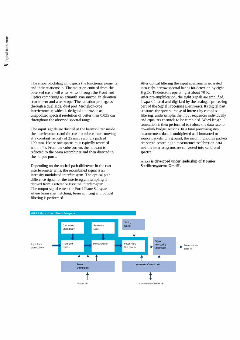
42
Payl
oad
Inst
rum
ents
After optical filtering the input spectrum is separatedinto eight narrow spectral bands for detection by eightHg:Cd:Te-detectors operating at about 70 K. After pre-amplification, the eight signals are amplified,lowpass filtered and digitized by the analogue processingpart of the Signal Processing Electronics. Its digital partseparates the spectral range of interest by complexfiltering, undersamples the input sequences individuallyand equalizes channels to be combined. Word lengthtruncation is then performed to reduce the data rate fordownlink budget reasons. In a final processing step,measurement data is multiplexed and formatted tosource packets. On ground, the incoming source packetsare sorted according to measurement/calibration dataand the interferograms are converted into calibratedspectra.
is developed under leadership of DornierSatellitensysteme GmbH.
The blockdiagram depicts the functional elementsand their relationship. The radiation emitted from theobserved scene will enter through the Front-ndOptics comprising an azimuth scan mirror, an elevationscan mirror and a telescope. The radiation propagatesthrough a dual slide, dual port Michelson-typeinterferometer, which is designed to provide anunapodized spectral resolution of better than 0.035 cm-1
throughout the observed spectral range.
The input signals are divided at the beamsplitter insidethe interferometer and directed to cube corners movingat a constant velocity of 25 mm/s along a path of 100 mm. Hence one spectrum is typically recordedwithin 4 s. From the cube corners the beam isreflected to the beam recombiner and then directed tothe output ports.
Depending on the optical path difference in the twointerferometer arms, the recombined signal is anintensity modulated interferogram. The optical pathdifference signal for the interferogram sampling isderived from a reference laser the interferogram. The output signal enters the Focal Plane Subsystemwhere beam size matching, beam splitting and opticalfiltering is performed.
SignalProcessingElectronics
Command & Control I/F
Instrument Control Unit
Power I/F
Power Distribution
StirlingCooler
Light from Atmosphere
MeasurementData I/F
Front-EndOptics
Interferometer Focal PlaneSubsystem
CalibrationBlack Body
ReferenceLaser
MIPAS Functional Block Diagram

Payl
oad
Inst
rum
ents
43
Cooler with Radiator
(Photo courtesy of Dornier)
Interferometer
Engineering Model
(Photo courtesy of Dornier)

44 Radar Altimeter 2 (RA-2)
The Radar Altimeter 2 is a dual-frequency (Ku-band, S-band) altimeter derived from the -1/2 RadarAltimeters, providing improved measurementperformance and new capabilities.
The main objectives of the -2 are the high-precisionmeasurements of the time delay, the power and theshape of the reflected radar pulses for the determinationof the satellite height and the Earth surfacecharacteristics.
-2 transmits radio frequency pulses which propagateat approximately the speed of light. The time elapsedfrom the transmission of a pulse to the reception of itsecho, reflected from the Earth’s surface, is proportionalto the satellite’s altitude. The magnitude and shape ofthe echoes contain information on the characteristics of the surface which caused the reflection.
On-board the satellite, -2 measures, with respect totransmission, the power level and time position of thesamples of the earliest part of the echoes from ocean, ice and land surfaces. This result is achieved by one ofthe new features on -2: a model-free tracker in the on-board signal processor keeps the radar echoes withinthe sampling window. Window position and resolutionare controlled by algorithms developed to suit thetracking conditions.
Operating over oceans, these measurements are used todetermine the ocean surface topography, thussupporting studies of ocean circulation, bathymetry,gravity anomalies and marine geoid characteristics.
The on ground processing of the radar echo power andshape enables the determination of wind speed andsignificant wave height in the observed sea area,contributing to weather and sea state forecasting.
Furthermore, the -2 is able to map and monitor seaice and polar ice sheets.
The new features of -2 enable it to extend itsmeasurements of altitude and reflectivity over land. The measurements will be used for the determination of Earth surface elevation, geological structure andsurface characteristics.
Payl
oad
Inst
rum
ents
Instrument Parameters
Range
764 km to 825 km
-10 dB to +50 dB
0.5 m to 20 m
+/- 100 µs wrt. UTC
Accuracy
< 4.5 cm (highest res.)
< 0.4 dB (bias)< 0.2 dB (residual)
< 5 % or 0.25 m
Altitude
Backscatter Coefficient
Waveheight
Measurement Datation
Operating Frequency
Bandwidth
Pulse RepetitionFrequency
Pulse Width IF Bandwidth
Operation Data Rate Mass Power
13.575 GHz (Ku-band)3.2 GHz (S-band)
320 MHz & 80 MHz & 20 MHz & CW (Ku-band)160 MHz (S-band)
1795.33 Hz (for Ku-band)448.83 Hz (for S-band)interleaved operation
20 ms6.4 MHz
continuously over full orbit100 kb/s110 kg161 W
Adaptive height resolution operation is implemented byselecting the bandwidth of the transmitted pulses. As a result, measurements over ocean are carried outwith improved accuracy at the highest resolution. Over land or ice or during transitions from one kind ofsurface to another, the tracking is maintained acceptingsometimes a certain degradation of the heightresolution.
Accurate altitude measurements over the ocean carriedout by -2 at the main frequency of 13.575 GHz areaffected by fluctuations in ionospheric characteristics.Measurements at a second frequency channel of 3.2 GHz enable corrections for this error.

Payl
oad
Inst
rum
ents
45
FlightDirection
3.2 GHz13.575 GHz
Sub-SatelliteTrack
Ku-bandTransmitter
Ku-bandFront End
S-band Transmitter
S-band Front End
Deramp Mixer
PowerSupply
InstrumentControl Unit
Receiver
FrequencyGenerationandConversion Unit
Chirp Generator
Signal ProcessorSubassembly
MeasurementData I/F
Power I/F Command & Control I/F
to all units
Ku
S
AdaptiveTracker
RA-2 Functional Block Diagram

46
Payl
oad
Inst
rum
ents
-2 Electronics
(Photo courtesy of Alenia Aerospazio)
-2 Antenna
(Photo courtesy of Alenia Aerospazio)

Payl
oad
Inst
rum
ents
47
Echo samples are processed on ground to account forcorrection and calibration data. On-ground algorithmsallow extraction of precise satellite altitude, wind speedand significant wave height over the oceans.
-2 is a nadir-pointing pulse limited radar altimeterwhich transmits frequency modulated pulses. The transmit pulses are generated in the ChirpGenerator by means of Surface Acoustic Wave ()devices, up converted in the Frequency Generation andConversion Unit and finally amplified by the HighPower Amplifier () or the S-band Transmitter (x),depending on the transmit carrier frequency. The uses a travelling wave tube whilst the xapplies solid state technology. The Ku-band Front EndElectronics () or the S-band Front End Electronics() feed the signals to be transmitted from the or the x respectively to the antenna which is designedas a dual frequency parabolic antenna.
The radar echo is received by the antenna and led viathe or the to the Microwave Receiver. Then each echo signal is mixed with a replica of thetransmitted chirp (deramping chirp) to map the echosignal from time into frequency domain. The resulting signal is filtered, amplified and down-converted. A phase detector produces the base band inphase and quadrature components. These signals are fedto the Signal Processing Subassembly () where theyare sampled and analog-to-digital converted. Then, a 128-point complex fast Fourier transform, square-modulus extraction and averaging are applied to the samples to produce an averaged signal powerspectrum.
A software implemented robust tracking algorithm keepsthe leading part of the echo spectrums independent oftheir shapes within the sampling window by appropriatepositioning of the deramping chirps such that they willcoincide with the echo signals and, if necessary, byappropriate adaptation of the chirp bandwidth andthereby of the sampling window resolution.
There are three chirp bandwidths available: 320 MHz,80 MHz and 20 MHz. In general, the tracking isperformed with the highest possible resolutioncorresponding to 320 MHz. A second trackingalgorithm controls the receiver gain.
For the initialization of the tracking and after loss oftracking an acquisition routine detects the radar echoesand presets the tracking parameters in order to allow thestart of the tracking. The indication of loss of track withthe following acquisition and transitions betweenacquisition and tracking are performed autonomously. The acquisition uses unmodulated radar pulses. The echo detection is performed from the end to thebeginning of the receive window in order to avoid raindetection.
Simultaneously to the tracking, the -2 performsperiodically internal calibration measurements. For thisthe transmit pulse is coupled into the receiver by meansof a calibration coupler (-100 dB) within the /.The signal is amplified, deramped, filtered etc. as thenormal radar echo signals are. The power spectrum ofthis signal which is extracted by the represents thepoint target response of the instrument thus indicatingall residual errors and distortions in the transmit/receivepath of the instrument (except the antenna and theantenna feeders which have to be characterizedseparately on-ground).
All measured data, the radar echo spectrum samples, the point target response spectrum samples, etc. togetherwith auxiliary data which are necessary for theevaluation of the measured data, e.g. the instrumentparameter settings, measurement datation data and otherare sent to ground for further processing. On command,the -2 is able to transmit also bursts of single radarecho samples ( outputs) to ground.
The -2 is developed under leadership of AleniaAerospazio.

48
The main objective of the Microwave Radiometer is the measurement of atmospheric humidity assupplementary information for tropospheric pathcorrection of the Radar Altimeter signal, which isinfluenced both by the integrated atmospheric watervapour content and by liquid water. In addition, measurement data are useful for the determination ofsurface emissivity and soil moisture over land, forsurface energy budget, investigations to supportatmospheric studies and for ice characterization. The instrument on-board -1 is a derivative of the radiometers used on the -1 and-2 satellites. It is a dual channel, nadir pointingDicke type radiometer, operating at frequencies of 23.8 GHz and 36.5 GHz.
In order to eliminate Earth’s irradiation, differentialmeasurements at two frequencies have to be performed.The optimal frequency setting is achieved by using onefrequency at the maximum and one at minimumattenuation. The frequencies 23.8 GHz ad 36.5 GHzare the result of a trade off between instrument(reflector) size required to cover a horizontal area on theEarth surface comparable to the -2 beam and themaximum sensitivity to water vapour change in theatmosphere.
With one feed horn for each frequency, the pointsvia an offset reflector at an angle close to nadir. Theinstrument configuration is chosen such that the 23.8 GHz channel is pointing in the forward direction,the 36.5 GHz channel in the backward direction with afootprint of about 20 km diameter for each beam.
The instrument design principle is based on thedesign for the -1 instrument as shown in thefunctional block diagram. In nominal Dicke operation,the measured antenna temperatures are continuouslycompared with an internal reference load at a knowntemperature. In instrument internal calibration mode,the receiver is either connected to a sky horn pointing tocold space (cold reference) or to a load at ambienttemperature (hot reference). The calibration range thus
covered is 3 K to 300 K with a reference temperatureaccuracy of better than 0.1 K. Instrument internalcalibration is performed every few minutes.
The microwave radiation is received by an offset feedparabolic reflector antenna, routed through a Dickeswitch assembly to a down converter which translatesthe K- and Ka-band signals to a suitable range. The signal is passed through a band limited amplifierto a synchronous detector. The detected signal isintegrated, sampled and the resulting level converted toa corresponding frequency which is measured. Thesemeasurement data, reference load temperatures andancillary data are routed to the / forfurther transmition.
Retrieval of antenna and brightness temperature valuesfrom measurement data is accomplished by groundprocessing. This considers ground calibration data,antenna characteristics and in-orbit characterizationdata.
For -1 the design of the had to be modifiedin some areas compared to its 1/2 predecessor tocomply with the different platform and missionrequirements. The structure is a new design using technology having the old deployable antenna replacedby a non-deployable one, fully integrated into theinstrument structure. The design of the CentralElectronics has been adapted to the revised internal andexternal interface requirements and to the change ofcomponents. The Local Oscillators feature a completelynew design where the Gunn Oscillators have beenreplaced by Dielectric Resonator Oscillators.
The is developed under leadership of AleniaAerospazio.
Payl
oad
Inst
rum
ents
Microwave Radiometer (MWR)
Switching Assembly
(Photo courtesy of )

Payl
oad
Inst
rum
ents
49
Instrument Parameters
Operating Frequencies
Dynamic RangeAbsolute Radiometric Accuracy
OperationData RateMassPower
23.8 GHz (K-band)36.5 GHz (Ka-band)
3 K … 300 K
better 3 K
Continuously over full orbit16.7 kb/s25 kg23 W
FlightDirection
20km 25km
35kmNadir
Sub-Satellite Track
Integrator
LO LO
Sky Horn
Power I/F Command & Controland Data I/F(to ICU common with DORIS)
SynchronousDetector
IFAmplifier
SwitchAssembly
v/fConversion
ReferenceLoad
23.8 GHzChannel
Feed Horn36.5 GHzChannel
Feed Horn23.8 GHzChannel
AntennaReflector
BaseInstrumentControl
Counter
RF Front End23.8/36.5 GHz
Time
Central Electronics Unit
Telemetry / Telecommand
Power
AmbientLoad
Performance Parameter
and Budget Data
MWR Functional Block Diagram

Payl
oad
Inst
rum
ents
Laser Retro-Reflector (LRR)
Laser
Flight Direction
Site
Sub-SatelliteTrack
-2 Laser Retro-Reflector
An identical will be flown
on -1
(Photo courtesy of )
A Laser Retro-Reflector will be mounted on the nadirpanel close to the -2 antenna to support satelliteranging and -2 altitude measurement calibration. The is a passive device which will be used as areflector by groundbased laser ranging stations usinghigh power pulsed lasers.
The operating principle is to measure on ground thetime of a round trip of laser pulses reflected from anarray of corner-cubes mounted on the Earth-facing sideof the satellite. The corner-cubes are designed to reflectthe incident laser beam back directly, making thereflected beam parallel to the incident beam within afew arcseconds.
The corner-cubes, made of the highest quality fusedsilica, work in the visible spectrum at two specifiedwavelengths (λ=694 nm and λ=532 nm). The corner-cubes are symmetrically mounted on a hemisphericalhousing with one nadir-looking corner-cube in thecentre, surrounded by an angled ring of eight corner-cubes. This will allow laser ranging in the field of viewangles of 360° in azimuth and 60° elevation around theperpendicular to the satellite’s -Zs Earth panel. The massof the is 2 kg.
The is developed by .
50

Payl
oad
Inst
rum
ents
51
500 km
FlightDirection
900 km
8 km
47°
Sub-SatelliteTrack
The primary scientific objective of the is toestablish continuity of the -1 and -2 data sets ofprecise Sea Surface Temperature (), thereby ensuringthe production of a unique 10 year near-continuousdata set at the levels of accuracy required (0.5 K orbetter) for climate research and for the community ofoperational as well as scientific users developed throughthe -1 and -2 missions.
The second objective is to perform quantitativemeasurements over land surfaces. The land and cloudmeasurement objectives will be met through the use ofan additional visible focal plane assembly, which willlead to indications of
• vegetation biomass,
• vegetation moisture,
• vegetation health and growth stage.
The visible channels will also contribute to themeasurement of cloud parameters, like water/icediscrimination and particle size distribution.
Advanced Along Track Scanning Radiometer (AATSR)
The is one of the most stable of several keygeophysical variables which, when determined globally,contribute to the characterisation of the state of theEarth’s climate system. The precise measurement ofsmall changes in provides an indication of quitesignificant changes in ocean/atmosphere heat transferrates, especially in the tropics; also it is known that smallamplitude anomalies occurring in specific areas aresometimes associated with massive atmosphericperturbations, leading to widespread and damagingchanges in the global weather system.
For example, the ‘El Nino’ anomaly in the tropical EastPacific is associated with a reversal of the atmospheric‘Walker Circulation’. This in turn creates widespreadperturbations to the global weather system. The exactcausal relationships between such phenomena are notfully understood but a significant ‘El Nino’-event canevolve from an anomaly of 2-3 K, and therefore the ability to detect, for example, a 10% change in theanomaly field will require measurements of the accuracyprovided by the series of () instruments.
The principle of removing atmospheric effects inmeasurements by viewing the sea surface from twoangles is the basis of the family of () instruments.
The objectives will be met through the use ofthermal infrared channels (centred on 1.6 µm, 3.7 µm,10.85 µm and 12 µm), identical to those on -1&2.Atmospheric modelling for -1 has shown that ,with its thermal channels and two-angle viewinggeometry, can achieve a global accuracy in of betterthan 0.5 K.

52 Instrument Parameters
Spectral ChannelsInfraredVisible
Spatial ResolutionRadiometric ResolutionSST AccuracySwath Width
OperationData RateMassPower
1.6 µm, 3.7 µm, 10.85 µm, 12 µm0.555 µm, 0.67 µm, 0.865 µm
1 km x 1 km0.1 Kbetter 0.5 K500 km
continuously over full orbit625 kb/s101 kg100 W
Black BodyElectronicsUnit
CoolerControlUnit
InfraredCalibrationTarget
VisibleCalibrationTarget Instrument
ElectronicsUnit
MeasurementData I/F
PowerI/F
Command &Control I/F
Infrared-VisibleRadiometer
ScanMirror
FocalPlaneAssembly
StirlingCycleCooler
DigitalElectronicsUnit
Performance Parameter
and Budget Data
AATSR Functional Block Diagram
Payl
oad
Inst
rum
ents

Payl
oad
Inst
rum
ents
53
Engineering Model
(Photo courtesy of -)
As with the thermal infrared channels, themeasurement philosophy with respect to the visiblechannels is to develop and exploit a capability formaking accurate quantitative measurements of radiationfrom the Earth surface, using an on-board calibrationsystem for radiometric accuracy, also using a two-angleviewing technique to obtain accurate atmosphericcorrections.
The most important two visible channels are centeredon 0.865 µm and 0.67 µm respectively and will providemeasurements of Vegetation Index in the same way as. The will have the capability for makingglobal measurements with 1 km x 1 km resolution atnadir. An additional visible channel at 0.55 µm is alsoincorporated, to indicate, from chlorophyll content, the growth stage and health of vegetation.
The functional principles are shown in the blockdiagram. The infrared-visible radiometer includes aninclined plane scan mirror which is rotated continuouslyin front of a reflecting telescope to provide a conicalscan. The cone axis projects downwards and ahead inthe along track direction of the satellite, achievingscanning across the satellite track in two regions. The Focal Plane Assembly () is equipped with anumber of oversized detectors, one per channel. A pairof Stirling Cycle Coolers, controlled by the CoolerControl Unit are used to cool the detectors to 80 K. Two blackbody infrared calibration targets controlled bythe Black Body Electronics Unit and a diffuse reflectorvisible calibration target are viewed between the nadirand along-track scans.
The electrical signals from the are conditioned bypreamplifiers which deliver the signals to the InstrumentElectronics Unit for further processing. The DigitalElectronics Unit () performs the data formatting andcommand & control functions. The also providesthe interfaces to the spacecraft.
The , developed under leadership of -, is a British/Australian contribution to the -1Mission.

Payl
oad
Inst
rum
ents
Doppler Orbitography and Radiopositioning Integrated by Satellite (DORIS)
is a microwave doppler tracking system used forprecise orbit determination with an accuracy in theorder of centimetres. In conjunction with the RadarAltimeter, contributes to improve the accuracy of the measurements of the spatial and temporal oceansurface topography changes and the variations in icecoverage. In addition, data are provided to:
• help in the understanding of the dynamics of the solid Earth,
• monitor glaciers, landslides and volcanoes,
• improve the modelling of the Earth gravity field and of the ionosphere.
is based upon the accurate measurement of the Doppler shift of radiofrequency signals transmittedfrom ground beacons and received on-board thespacecraft. Measurements are made at two frequencies:2.03625 GHz for precise Doppler measurements and at401.25 MHz for ionospheric correction of thepropagation delay.
The System comprises the on-board instrument, a beacon network and the Control and DataProcessing Centre. For operational aspects the control centre provides an interface to the spacecraftFlight Operation Segment. The instrumentcomprises a fixed omnidirectional dual frequencyantenna and a redundant receiver controlled by an UltraStable Oscillator ( identical to the s employed in the ground segment of ). The receiver performsthe Doppler measurements every ten seconds. The receivers have the capability to track simultaneouslytwo beacons. The reference frequency for the Dopplermeasurement is generated by the with a stability of5 x 10-13 over 10 to 100 seconds. The orbitdetermination beacons are deployed on a dense world-wide network. The location of these beacons is preciselylinked to an international reference frame to get absolutepositioning. The time and frequency reference scale forthe whole system is provided by the master beacon,connected to atomic clocks.
The Control Centre performs the instrument andbeacon control on the basis of telemetry datamonitoring and operational orbit determination.
On-board measurements of the Doppler shift areperformed every 7 to 10 seconds. Resulting radialvelocity values (accuracy of the order of 0.4 mm/s) areused on ground in combination with a dynamic modelof the satellite trajectory to perform a precise orbitdetermination with an accuracy of better than 5 cm inaltitude. These orbit data are available within a month.The delay is mainly due to the availability of externaldata, such as solar flux.
The Doppler measurements are also processed on-boardto obtain real-time orbit data, with less accuracy, butavailable for use in the Near Real Time processing at the stations.
is provided to the -1 Programme by theFrench Space Agency .
Omnidirectional Antenna
(Photo courtesy of )
54

Payl
oad
Inst
rum
ents
55
Instrument Parameters
Measurement Frequencyfor Doppler Measurementfor Ionospheric Correction
Position AccuracyReal-TimeRestituted
Velocity AccuracyReal-TimeRestituted
OperationData RateMassPower
2.03625 GHz401.25 MHz
1 m0.05 m radial
< 2.5 mm/s0.4 mm/s
continuously over full orbit16.7 kb/s91 kg (incl. ICU)42 W
FlightDirection
Sub-SatelliteTrack
DORIS beacons
aux. data: maneuvers, etc...
Commands
Measurements Precise Orbit
Telemetry
DORISPrecise Orbit Determination
DORIS Control andData Processing Center
BeaconsInstallationand Maintenance
MasterBeacon
AtomicClock
Orbit DeterminationBeacons Network
Shared Elements(with other DORIS missions)
ENVISAT-1 Elements
FOS&PDS
Performance Parameter
and Budget Data
DORIS System Block Diagram

The primary scientific objective of is theglobal measurement of various trace gases in thetroposphere and stratosphere, which are retrieved fromthe instrument by observation of transmitted, backscattered and reflected radiation from the atmosphere inthe wavelength range between 240 nm and 2400 nm.The large wavelength range is also ideally suited for thedetermination of aerosols and clouds. The nadir and limb viewing strategy of yields total column values as well as profiles for tracegases and aerosols in the stratosphere. This enables, inaddition, estimates of global trace gas and aerosolcontent and distribution in the lower stratosphere andtroposphere.
The measurements obtained from willenable the investigation of a wide range of phenomenawhich influence atmospheric chemistry:
• in the troposphere: biomass burning, pollution, arctic haze, forest fires, dust storms, industrial plumes,
• in the stratosphere: ozone chemistry, volcanic events and solar proton events.
In order to achieve the scientific objectives,measurements are performed by observing theatmosphere under different viewing angles. In NadirMode, the global distribution (total column values) ofthe atmospheric trace gases and aerosols will beobserved. Additionally, cloud measurements areobtained. In this mode, the instrument is scanningacross-track, with a swath width of ±500 km withrespect to the subsatellite track. To obtain the altitudedistribution of trace gases, performsobservations in limb over an altitude range of 100 km,with a vertical resolution of 3 km. Starting at Earthhorizon, the atmosphere is scanned tangentially over a1000 km wide swath. After each azimuth scan, theelevation is increased until the maximum altitude of 100 km is reached.
Payl
oad
Inst
rum
ents
Scanning Imaging Absorption Spectrometer for Atmospheric Cartography (SCIAMACHY)
Differential Optical Absorption Spectroscopy is appliedin sun and moon occultation measurements, where sunor moon are either tracked or a vertical scan over thecomplete sun/moon surface is performed. The obtainedspectra can then be compared with suitable calibrationspectra to yield the differential absorption of the atmosphere.
In the optical assembly, the light from theatmosphere is feed by the scanner unit consisting of anazimuth and an elevation scanner into the telescopewhich directs it onto the entrance slit of thespectrometer. The spectrometer contains a pre-disperserwhich separates the light into three spectral bandsfollowed by a series of dichroïc mirrors which furtherdivide the light into a total of eight channels. A grating is located in each channel to diffract the lightinto a high resolution spectrum which is then focusedonto eight detectors. The pre-disperser also serves as aBrewster window to separate polarised light, a part ofwhich is sensed by the Polarisation Measurement Device(). The output of the is later used to correct forthe polarisation effects. Light reflected off the slit isdirected to the Sun-Follower which controls the scanmirrors in the Sun and Moon Occultation mode.Each spectrometer channel is equipped with a DetectorModule consisting of the detectors and their DetectorModule Electronics (). Each controls itsassociated detector, reads out the integrated charge,amplifies the analogue signal and then digitises thissignal. The digital signal of each channel is transferred tothe Science Data Processing Unit ().
56

Payl
oad
Inst
rum
ents
57
Na
dir
80
0 k
m
1000 km x 1.3 kmLimb
0 km
100
km
Tangential Height
1000 km16 km x 32 km
Sub-SatelliteTrack
Instrument Parameters
Sciamachy Performance Parameter and
Budget Data
Channel
12345678
PMD 1 to 7
SpectralRange
240-314 nm 309-405 nm 394-620 nm 604-805 nm
785-1050 nm 1000-1750 nm 1940-2040 nm 2265-2380 nm
310-2380 nm
SpectralResolution
0.24 nm0.26 nm0.44 nm0.48 nm0.54 nm1.48 nm0.22 nm0.26 nm
67 to 137 nm(channeldependent)
High Resolution Channels
Polarisation MeasurementDevices (broadband)
Altitude Range
Vertical Resolution
Operation
Data Rate
Mass
Power
10 km -100 km depending on measurement mode
2.4 km - 3 km depending on measurement mode
continuously over full orbit
400 kb/s nominal; 1867 kb/s real time mode
198 kg
122 W

58
Payl
oad
inst
rum
ents
Optical Assembly
PMD Data
AUX Data
Power I/F Command & Control I/F
MeasurementData I/F
Light fromAtmosphere
InstrumentControl Unit
Telescope Spectrometer Detector ModulesScience Data
Processing Unit
PolarizationMeasurement
DeviceSunfollower
Radiant CoolerAssembly
Cal Lamps
Scanner Unit
DHCMEncoder Electronic
Power, Mechanism & Thermal Control Unit
SCIAMACHY Functional Block Diagram
To achieve the required instrument performance thedetectors of the Optical Assembly have to be cooled toaround 200 K for the visible and channels 1 to 6and to around 135 K for the channels 7 and 8. Thiscooling is provided by the Radiant Coolerwhich is coupled through a Thermal Bus Unit () tothe detectors of the Optical Assembly. The is buildup from two cryogenic heatpipes which cool the two -detectors. A tube shaped shroud, which envelopes the cryogenic heatpipes, transports the heat load fromthe detectors of the other six channels. The controls the , acquires and processesscience and auxiliary data and transmits them to the /measurement data interface. The Instrument ControlUnit receives the macrocommands from the /,performs autonomously the overall management andcontrol of the instrument and feeds back telemetry
information. The Power, Mechanism and ThermalControl Unit () provides secondary power to allequipment and controls the scanners (via the EncoderElectronics), the different mechanisms, the calibrationsource and the temperature of the optical bench and the detectors. Furthermore the acquires analoguehousekeeping signals indicating the health and status ofthe instrument. A Decontamination Heater Control Module ()performs the Radiant Cooler decontamination on/offcontrol and the thermal knife control.
is developed by a trilateral German/Dutch/Belgian activity under , and contract involving Dornier Satellitensysteme GmbHand Fokker Space as the leading companies.

Tit
el h
oofd
stuk
59
Optical Assembly
(Photo courtesy of Fokker Space)
Electrical Assembly
(Photo courtesy of Dornier)

Model PhilosophyThe -1 instrument design and development logicand model philosophy are driven by the need toimplement a cost effective approach fulfilling thestringent technical requirements within acceptabletechnical and programmatic risk. Furthermore its modelphilosophy is strongly linked to the programme inform of the deliverables from -1 to and withrespect to the qualification programme implemented.
Since the -1 instruments range from completelynew instruments up to rebuild of existing instrumentswith minimum adaptation for accommodation on they have to be treated from a design and developmentpoint of view quite individually.
Some specific considerations with respect to the programme arose also from the fact that for alreadyqualified instrument designs no instrument EngineeringModel () are available. Furthermore cost and scheduleconstraints led in several cases to the delivery of reduced instruments to the programme which show fullinterface and dedicated operational representativity, butno relevant scientific performances. The baselineestablished now, constitutes an adequate compromise onboth sides.
The following instrument hardware models are to bedelivered to the spacecraft programme:
• Mock-ups (’s),
• Structure Models,
• Engineering Models, and
• Flight Models.
The s support the spacecraft level Radio Frequency() analysis by measuring antenna coupling factorswith the / mock-up. representative developmentmodels of the -2, and antennas have beendelivered. Structure Models (StM’s) have been delivered to the structure qualification programme for instruments orassemblies with a first eigenfrequency below 100 Hz.The delivered instrument StM’s are of flight structurestandard.Engineering Models (EMs) are delivered to supportmainly the functional verification of the overall satellite.For the rebuild instruments (, and ) noEMs are provided. Electrical interface and functionalrepresentative reduced EMs have been delivered for, and . Flight Models () willbe delivered to the programme fully verified and
characterized on instrument level with the exception of, where the antenna and the central electronics willbe delivered separately to the / programme forintegration and testing.
Instrument Development and VerificationThe -1 instruments are composed of Developed Instruments (’s) and Announcement ofOpportunity Instruments (’s) with modelcharacteristics as shown.
For newly developed instruments, performancerepresentative EMs have been developed to gainconfidence as early as possible that the instruments canfulfil their mission objectives. Instrument s are flightrepresentative in form, fit and function. They areequipped with commercial components suitable forthermal vacuum testing. Redundancies are not requiredfor the instrument units.
Design qualification is performed to the maximumextent possible within the given programmaticconstraints on the . For selected equipment, Proto-Flight Model () approaches are applied.Instrument verification is completely performed atinstrument level against -1 requirements, i.e. as a general rule no satellite level tests are needed forinstrument design qualification purposes, however thesatellite level tests must prove that the environment,under which the instrument design was qualified, iscompatible with the actual environment. When theinstruments are integrated on the satellite, an -1payload related verification programme will beperformed in order
• to demonstrate compliance to -1 requirements related to the complete payload,
• to verify the satellite functions with the integrated payload as part of the verification programme.
• to verify compatibility with the actual level environment.
The main objective of the satellite programme is to confirm that the fully integrated satellite is fit for itspurpose and ready for flight.
Payl
oad
Inst
rum
ents
60 Development and Verification Programme
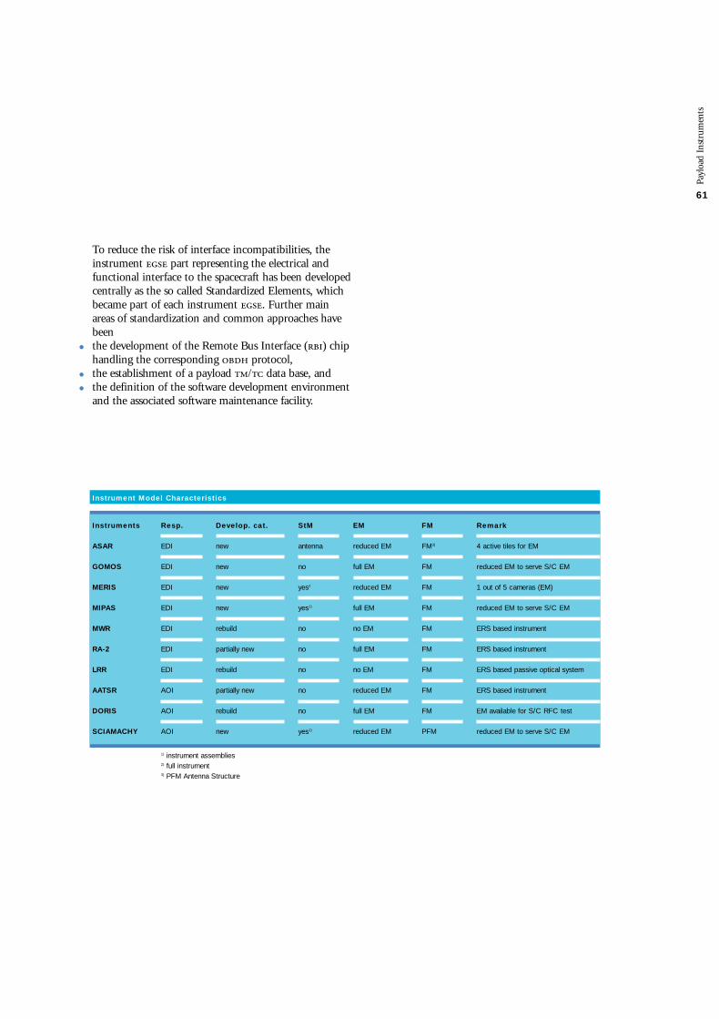
Payl
oad
Inst
rum
ents
61
To reduce the risk of interface incompatibilities, theinstrument part representing the electrical andfunctional interface to the spacecraft has been developedcentrally as the so called Standardized Elements, whichbecame part of each instrument . Further mainareas of standardization and common approaches havebeen
• the development of the Remote Bus Interface () chip handling the corresponding protocol,
• the establishment of a payload / data base, and
• the definition of the software development environment and the associated software maintenance facility.
Instrument Model Characteristics
Resp.
EDI
EDI
EDI
EDI
EDI
EDI
EDI
AOI
AOI
AOI
Develop. cat.
new
new
new
new
rebuild
partially new
rebuild
partially new
rebuild
new
StM
antenna
no
yes2
yes1)
no
no
no
no
no
yes1)
EM
reduced EM
full EM
reduced EM
full EM
no EM
full EM
no EM
reduced EM
full EM
reduced EM
FM
FM3)
FM
FM
FM
FM
FM
FM
FM
FM
PFM
Remark
4 active tiles for EM
reduced EM to serve S/C EM
1 out of 5 cameras (EM)
reduced EM to serve S/C EM
ERS based instrument
ERS based instrument
ERS based passive optical system
ERS based instrument
EM available for S/C RFC test
reduced EM to serve S/C EM
Instruments
ASAR
GOMOS
MERIS
MIPAS
MWR
RA-2
LRR
AATSR
DORIS
SCIAMACHY
1) instrument assemblies2) full instrument3) PFM Antenna Structure

The programme commits to generate engineering andgeophysical products from the observations performedby the -1 satellite instruments. It implies that thefollowing activities are performed prior to the -1launch:
• product definition and processing algorithm development and implementation;
• generation of test data and use of Instrument System Simulators;
• instrument characterisation;
• preparation of the in-orbit calibration;
• preparation of the level 2 product validation.
Product definition and Processing AlgorithmsTo ensure coherency of the data product definition,algorithm definition and validation, as well as coherency,within the , between Near real Time and Offlineproducts, a comprehensive development programme hadto be put in place, implying in particular:
• provision of precise product guidelines applicable to all products;
• provision of a suite of mission software to ensure proper use of orbit data and proper geometry calculations forgeolocation through all products;
• development of instrument system simulators whenever reconditioning of in-flight acquired data from similarinstruments are not available;
• Setting up of Expert Support Laboratories (s) and supporting industries to document the products,develop and document the algorithms, test them onprototype processors using simulated data and later onparticipate to the product validation;
• Setting up of Science Advisory Groups (s), per instrument, to advise the Agency on instrument performances, product definition, processing algorithms and validation approach issues.
By the time of the -, all level 1B and level 2products formats are defined. It has been possible to define product formats andprocessing algorithms which are common to both Nearreal Time and Offline Products, the difference being inthe quality of the auxiliary data available at processingtime (calibration parameters, orbit data and supportingmeteorological information).
All -1 products follow the same product formatstructure which permits providing to the users:
• a coherent product inventory with efficient search mechanisms;
• simple software tools for opening and reading products,
• generation of products as a continuous stripe for an acquisition segment with possibility to deliver eitherthe stripe or extracted scene products as well as to selectsubsets within a product (i.e. subsets of spectral bands).
For all instruments, but and , the detailedproduct definition and processing algorithmdocumentation is produced by s with the help ofsupporting industries and delivered to the consortium for implementation of the correspondingoperational processors.
All processing algorithms are prototyped by s inorder to validate the documentation produced and togenerate reference test data to be used for the acceptancetesting of the processors.
All processing chain developments have beenstarted, except for for which the provided Detailed Processing Model documentation isplanned for the fall 1997. For the imageprocessing, due to the past industrial experience , the development is performed directly based uponimage quality requirements. For , the multimissionprocessing chain is already available at , thisinstrumentation being already exploited on several in-flight missions.
Instrument System SimulatorsIn the frame of the payload development programme,Instrument System Simulators for , , and -2 have been developed. For , the instrument provider has also developed a similarsystem simulator.
The end-to-end instrument system simulators includethe simulation of the target, the signal path from targetto instrument, the orbit and attitude of the satellite, theinstrument (including analog part and digital signalprocessing) and are capable of generating simulatedinstrument data in the specified instrument format(Instrument Source Packets).
Prod
ucts
& S
imul
atio
ns
62 Products & Simulations
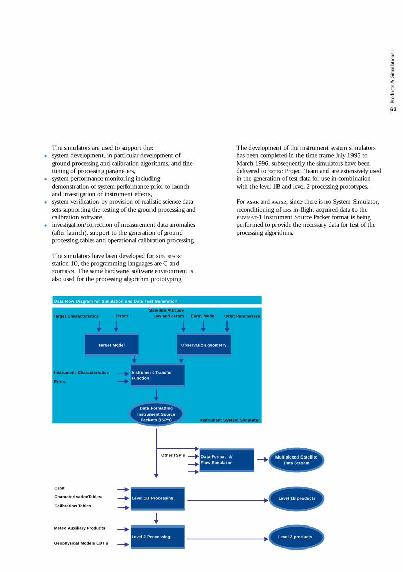
The simulators are used to support the:
• system development, in particular development of ground processing and calibration algorithms, and fine-tuning of processing parameters,
• system performance monitoring including demonstration of system performance prior to launchand investigation of instrument effects,
• system verification by provision of realistic science data sets supporting the testing of the ground processing andcalibration software,
• investigation/correction of measurement data anomalies (after launch), support to the generation of groundprocessing tables and operational calibration processing.
The simulators have been developed for station 10, the programming languages are C and. The same hardware/ software environment isalso used for the processing algorithm prototyping.
Prod
ucts
& S
imul
atio
ns
63
Target Characteristics ErrorsSatellite Attitude
Law and errors Earth Model Orbit Parameters
Target Model Observation geometry
Instrument Characteristics
Errors
Instrument Transfer Function
Data Flow Diagram for Simulation and Data Test Generation
Instrument System Simulator
Other ISP's Data Format & Flow Simulator
Multiplexed Satellite Data Stream
Orbit
CharacterisationTables
Calibration Tables
Level 1B Processing Level 1B products
Meteo Auxiliary Products
Geophysical Models LUT's
Level 2 Processing Level 2 products
Data Formatting Instrument Source
Packets (ISP’s)
The development of the instrument system simulatorshas been completed in the time frame July 1995 toMarch 1996, subsequently the simulators have beendelivered to Project Team and are extensively usedin the generation of test data for use in combinationwith the level 1B and level 2 processing prototypes.
For and , since there is no System Simulator,reconditioning of in-flight acquired data to the-1 Instrument Source Packet format is beingperformed to provide the necessary data for test of theprocessing algorithms.

The Data Format and Flow simulator (DFFS)The Data Format and Flow Simulator comprises thesimulation of the on-board measurement data stream(including the High Speed Multiplexer) and thetransmission to ground. The was completed inJanuary 1997.
Using the simulated instrument data, provided by theSystem simulators, and the reconditioned data, the is used to provide simulated multiplexed datastreams for test of the data acquisition andprocessing chains. Some referenced orbit scenarii havebeen defined, all simulated data adhere to these scenarii.
Instrument CharacterisationA detailed list of instrument elements to be characterisedbefore launch has been established. The correspondingcharacterisation results, to be obtained during onground verification test of the Flight Model instruments,will be provided via computer file for use in the level 1Bprocessing algorithms.
In-flight CalibrationThe in-flight calibration requires processing of dataacquired via:
• use of instrument internal calibration loops, the instrument carrying its own stimuli;
• use of instrument external well characterised stimuli, natural targets (i.e. stars, rain forest , deserts or icesheets) or specific artificial targets (i.e. transponders)
The corresponding results will be processed off-line inthe Instrument Engineering Calibration Facility (),specifically equipped for handling these data and forgenerating the calibration tables to be delivered to the for the corresponding level 1B processing chains.
Level 2 Algorithm ValidationThe level 2 processing algorithms use numerous modelsto convert engineering quantities into geophysicalparameters (i.e. absorption lines into atmosphericspecies, brightness temperatures into surfacetemperatures, radar cross section return echo into windor wave). Wherever possible these models are beingvalidated using the experience acquired before -1launch, using in particular data acquired in-flight (whenavailable) or airborne campaign data.
During -1 in-orbit Commissioning, it is planned to use two approaches in parallel:
• pre assimilation of level 2 products by operational centres (i.e. meteo centres),
• comparison with in situ data on specially equipped campaign sites.
These two approaches have been shown to becomplementary and extremely powerful in the -1 and 2 missions:
• the in situ data provide precise measurements within the constraints of well identified sites;
• the pre-assimilation of data products provides comparison with operationally used models, thisproduct analysis, on a global scale, permits potentialphysical problems in the overall behaviour of theinstrument processing algorithm to be highlighted.
Preparation for In Orbit CommissioningAs shown above, the provision of level 1B and level 2products to users requires the setting up of acomprehensive list of complementary activities inparallel with the satellite development phase. Theseactivities aim at preparing the in-orbit CommissioningPhase: all processing chains have to be operable withcorresponding mechanisms for updating the tunableparameters (Look Up Tables for the level 1B calibrationparameters and for the level 2 model validationparameters). Within the 6 months duration of theCommissioning phase, the calibration activities willpermit to deliver level 1B products. The validation of the level 2 products shall be such that, by the end of this phase, products will start to be delivered to theusers.
Prod
ucts
& S
imul
atio
ns
64

Total observed by on -2
(Photo courtesy Anke Piters )
Simulated MERIS Chlorophill
image (level 2 product) in the
vicinity of Cyprus, built up from a
composite of CZCS images
processed by the Laboratoire de
Physique Chimie Marine (France).
Image Cross Spectrum
(level 1B) product derived from
-2 SAR data. The Ocean Wave
Spectrum (level 2 product) is
subsequently obtained by applying
the Transfer Function from
image spectra to ocean wave spectra.
0.00RangeWavenumber[rad/m]
AzimuthWavenumber[rad/m]
0.15
– 0.15– 0.15
– 0.10
– 0.05
0.05
0.10
0.00
0.15
5
10
15
20
– 0.10– 0.05
0.050.10
– 0.10– 0.10
– 0.05
0.00
0.05
0.10
– 0.05 0.00Range Wavenumber [rad/m]
Azi
mut
h W
aven
umbe
r [r
ad/m
]
0.05 0.10
3 7 11 15 19 23 27 31 mg/m3
Chlorophyll A concentration

66
The Flight Operation Segment () providesmonitoring and control of the satellite for all in-orbitoperations.The Flight Operation Control Centre (), located at Darmstadt, hosts the following major subsystems:
• The Flight Operation Control Software;
• The Flight Dynamics Software;
• The Mission Planning System;
• The -1 Satellite Simulator;
• The Data Archiving System;
• The Satellite Software Maintenance Facility.
The provides also all the communicationinterfaces, internal to the as well as externalinterfaces to the and to the specific entitiessupporting the Mission Operation.
The Flight Operations Control Software is based on the-1 system successfully used on the missions:this approach presents minimum development risks witha system capable of fulfilling all specified userrequirements.
The Flight Dynamics Software is derived from the system, already used on the missions. The major upgrade is the addition of the Star trackercontrol and performance monitoring.
The Mission Planning System () is a newdevelopment. The functions and correspondingrequirements are specific to the mission but thesplit of responsibilities between the and the Mission Control Facility is very similar to the missions. The Global Mission planning, specified in theReference Operation Plan (), is directly planned bythe ; the Regional Mission scheduling, mainly drivenby user requests, is built up at the and transferredto the as a Preferred Exploitation Plan (). The is in charge of building up the completesatellite scheduling sequence, verifying the compatiblitybetween the satellite constraints and the operationrequirements of the and the . The correspondingsatellite operation schedule is delivered to the as aDetailed Mission Operation Plan and implemented via aset of time tagged macrocommands routed form the to the satellite via the station of Kiruna.
The -1 Satellite Software Simulator is built to beas representative as possible of the on-board software forall aspects related to satellite control in all missionphases (, routine operations and contingencies).
This simulator includes emulation of the flight softwareof the Service Module and Payload Module Computerand simulations of the other satellite subsystems,including the Instrument Control Units. The mainobjective is to permit rehearsals of all critical operationsas well as to train the operators in the execution ofnominal and contingency procedures.
The Performance Analysis System will allow the storageand retrieval of satellite control and monitoringinformation throughout the complete mission lifetime.
The Satellite Software Maintenance Facility is based onsoftware maintenence tools delivered by the satellite andinstrument manufacturers. For the software of theService Module, due to its mission criticality andcomplexity, a significant part of the maintenanceactivities will remain with the corresponding satellitecontrator.
The Kiruna Station upgrade, includes refurbishment ofthe existing 15 meter antenna, upgrade of the partand installation of the X-band receiving chains,including the demodulators.
The development of all the software systems is on going. A phased delivery is foreseen for the FlightControl Software. This will permit a step by stepintegration at the and the verification of thesatellite compatibility via the System Verification Tests.Between end 1997 and satellite shipment to the launchpad, 4 campaigns of System Verification Tests (’s) areplanned; during these ’s, the satellite will be directlyunder control of the Flight Control Software.These ’s will permit, in particular, the criticalsequence of activities foreseen during the Launch andEarly Orbit Phase () to be tried out.
FOS

Attitudeaquisition
Launch
Kourou
Injection
L7 stage
Separation
Solar arrayMEGS release
Solar arrayrotation
Solar arraysecondary deployment
Solar arrayprimary deployment
Rate reductionmode
ASAR instrumentdeployment
Wheel controlledfine pointing mode
67
Satellite Control Room at the Flight
Operation Control Centre ()
ENVISAT-1 Launch and Early Orbit Phase (LEOP) Sequence

68
PDS
The Payload Data Segment () provides all servicesrelated to the exploitation of the data produced by theinstruments of on-board the -1 satellite.The comprises provided centres and stations:
• The Payload Data Control Centre () at ,
• The Payload Data Handling Stations (’s) at and Kiruna,
• The Payload Data Acquisition Station () at Fucino,
• The Low rate Reference Archive Centre () at Kiruna
as well as centres and stations procured nationally:
• The Processing and Archiving Centres (’s) located in member states,
• The National Stations providing Services () and located in programme participating states. The will also interface with national and foreignstations duly authorised to receive -1 regionaldata.
The at , is in charge of instrument andground segment planning, and of overall monitoring and control. It also co-ordinates user servicesand provides quality and engineering support for theproducts.
The ’s at and Kiruna acquire measurementdata downloaded by the spacecraft (respectively in Ka-
and X-band), process it and disseminate products,according to directives. A short term rollingarchive is provided. Local services are also offered tousers.
The at Fucino acquires only measurement data (in X-band) and forwards it to the at forprocessing.
The at Kiruna archives and processes the globallow rate data off-line, to provide a completeconsolidated low rate level 1B data set for s (Developed Instruments) and - Instruments, and a pre-consolidated level 1B for other ’s(Announcement of Opportunity Instruments). Localservices are also offered to internal users.
The ’s located in member states, archive andprocess off-line high rate data and generate off-linegeophysical products for regional High Rate or FullResolution instruments and global Low Rateinstruments.
s and s, while developed from national funds, willuse some elements, known as ‘Generic Elements’,designed and developed as part of the industrialcontract.
Acquisition ofX-band signals
Providing services to users
Providing services to internalusers
Providing services to users
Administration & Coordinationof user services
Providing services to users
Planning, M&C of PDHSactivities and resources
Planning, M&C of LRACactivities and resources
Planning, M&C of PDCCactivities and resources
Planning, M&C of SystemMission and resources.Interface with FOS
Planning, M&C of PACactivities and resources
Monitoring of product quality
Engineering support to PDSactivities
Generation ofNRT products
Cleaning andconsolidationof LBRproducts
Generation ofhigher levelproducts
RollingArchive
Archiving ofLBR level 0 &1B products
SoftwareBrowsesArchiving
Archiving ofgeneratedproducts
Disseminationof NRTproducts
Productsdissemination
Productsdissemination
Productsdissemination
PDS Centre & Station functions
PDHS
LRAC
PDCC
PACs
Product Generation
Acquisition Demultiplexing Processing
Products Administration
Archiving Dissemination
User Services
Access to service Production Inventory
Supervision
System Supervision PlanningMonitoring & Control (M&C)
Support to production
Product control Engineering support
Centres/stations their function and location

69
PDHS Architecture and OperationThe operation strategy is defined at the . Thecorresponding instructions are passed to the CentreMonitoring and Control () of each .
At the beginning of a pass (period corresponding to theacquisition of measurement data for a single orbit), allproduction facilities as well as the archiving anddissemination facilities receive the instructions from the for the operations to be performed.
The Acquisition Facility () acquires the satellite signal,using Ka- or X-band. It sends raw data s to theFront End Processor (), and records themsimultaneously on media for backup.
The assembles the Instrument Source Packets (’s)to be delivered to the Processing Facility ().
What are the PDS facilities?Each centre or station has to fulfil a set of servicesand functions.
Many common functions are implemented in differentcentres and stations. For example the ’s, and’s have to process instrument data to generateproducts: the algorithms to be implemented areidentical, only the quality of the auxiliary data used forthe processing will be different.
Another example concerns the user services to beoffered: they shall be identical, and the level and qualityof the service shall be independent of the centre that theuser accesses.
The major design driver has been to define a modulararchitecture requiring a minimum set of facilities. Thesefacilities will be assembled to construct the different centres and stations and will be available as GenericElements for the ’s.
PDS architecture
Kiruna Salmijarvi Station
(Photo courtesy of Dornier)

70
The , which comprises of the host structure and thedifferent Instrument Processor Facilities (’s), generatesNear Real Time () products from the ’s usingauxiliary data retrieved from the Archiving Facility(), and sends them to the .
The stores the products in the on-line archive andsends associated product headers to update theentory ().
In parallel, the Dissemination Facility () retrievesproducts from the and disseminates them on theground network or on the satellite data disseminationchannels according to the instructions provided by the.
At any time, users can query the through the UserService Facility (), and ask, for example, for the on-line delivery of browse or small products.
The products generated at the (level 0, 1B and 2)are copied and delivered on physical media to the ’sand the .
The reports to the on the operationsperformed by the .
AF PF ARF
INV
USF
DF
Centre Monitoring & Control
CADUs ISPsProducts
Aux dataAux data
Raw Data On Media
Products
Queries& Results
Browses & small Products User access
to services
Products On Media
Product deliveryto users
2 Mbps
64 Kbps
Ground Networks
FEP
Functional architecture of a PDHS

71
PDHS ESRINPDCC
PDHS Kiruna
LRAC
Maspalomas
S-PAC
D-PAC
UK-PAC
F-PAC
I-PAC
Ka-ba
nd
Ka-band
X-band
ASAR High Rate
MERIS Full Resolution
ALTIMETRY & ASAR WAVE
ATMOSPHERECHEMISTRY
AATSR
MERIS ReducedResolution
to be shared between UK-PAC, D-PAC and I-PAC
to be shared between UK-PAC, I-PAC and Maspalomas station
located at F-PAC
located at D-PAC(with FMI Finland for GOMOS)
located at UK-PAC
located at S-PAC (Kiruna-Salmijärvi)
PAC Assignments
Centre/Station architecture overviewAll centres/stations are built from the same group offacilities, by selecting specific elements to meetparticular requirements.
Any national centre or station providing services (’s or ’s) will use generic elements at least forthe following 3 functions: data processing, user services() and centre monitoring and control ().
This will guarantee to the user uniform serviceswhatever station or centre is selected for processingand product delivery.
Centre/Station hardware architectureThe architecture is based on a specific set of computers:
• The 2 for all the processing chains: its multi computer capability is used to dynamically allocate onecomputer at a given time for the processing of oneproduct. The global throughput is simply obtained byadding up computers according to the requiredthroughput performances.
• The J40 for the , with state of the art robotics and media for automatic handling of archived products,
• The 43 P workstation for the other facilities,
• (high speed data link) for internal product distribution,
• Ethernet for the Monitoring & Control and User services.

72
http protocol
UsersWorld WideWeb
Helpdesk
Services Types
Consultation
Retrieval
Inventory
Order
Administration
Services
Directory (description of user services bulletin board information on tools)
Guide
Browse
Free software tools
Inventory
Restricted software tools
Get auxiliary data
Get product
Get On-demand product
Order future product
Subscription for global products
Order for acquisition
Request for dissemination link
Register user
Get account information
Complaint
ServicesAvailability
Free
Free
Free
Free
Free
Restricted
Restricted
Restricted
Restricted
Restricted
Restricted
Restricted
Restricted
Free
Restricted
Free
Centre providing services
Local centre
Local Centre or archivesin PDS centres
Inventories in PDScentres
PDCC or station centre
PDCC
ENVISAT Products
The main objectives of the are to generate,archive and distribute to the user’s community the products derived from the data collected by thesatellite.
archive will include data products from allinstruments over the satellite lifetime (nominally 5 years). This huge data flow can be summarised asfollows:
• up to 22 Gbytes of data to be acquired and processed every 100 minutes at ;
• 700 Gbytes of data exchanged every week between the centres and stations, representing up to 100 tapesdistributed.
• a total volume of 1000 Tera bytes of data to be archived over the whole mission.
User Services

73
The architecture leads to the build up of stationsand centres by the assembly of facilities. It implies thefollowing development and integration logic:
• facilities are developed by subcontractors and acceptance tested at this level;
• Assembly, integration and testing of the various facilities is performed on a reference platform, representing theconfigurations of the , , and a reference;
• The full deployment and assembly of facilities is then performed at the sites for a final onsite acceptancetest
testing will make extensive use of instrument testdata provided by through the use of instrumentsimulators or reconditioning of in-flight data.
The Critical Design Review was held in July 1996,and the Detailed Design Review took place inMarch 1997.
A first version of the , version 1, will be installed at. This version will allow a complete system overallvalidation with the other elements of the system. Generic elements for assembly will beavailable with version 1.
Full operations will be possible with version 2,includes the processing of all instruments.
User access to the PDS
Users will access the mainly to order data to beacquired, products to be processed or copied from thearchive. The will offer the following type of services, some ofthem being restricted to registered users only:
• Consultation accesses general information on mission, products and services,
• Retrieval allows the transfer on the User’s workstation of some data, such as Browse,
• Inventory supports the search of existing products in the archives,
• Order allows the user to request the production and the delivery of products either on physicalmedia or directly through electronic links,
• Administration helps the user to dialogue with the support operators.
Access to the services will be provided through Internet,via a erver installed at each centre and stationlocation. All services will be transparently provided tothe users by any access point.
Once connected, the user will be able to retrieveinformation on the products and services, to placeor modify an order, and to retrieve the status of anyorder previously registered. The display of graphicalinformation is maximised to help the users: satellitetracks, instrument coverage, outline of products will bedisplayed on a world map.
Users’ orders are analysed in real time to check theircompatibility with the -1 capability, the userprivileges according to data policy rules, and also toidentify possible conflicts among user requests.
All users’ orders requesting acquisition of data by thesatellite are centralised at the for the constructionof the satellite work plan, called the PreferredExploitation Plan (). In case of conflicts betweenorders a priority scheme is used to select among theorders.
The is submitted to the and the DetailedMission Operation Plan () is returned by the permitting the satellite scheduling and thecorresponding station/centre schedules to beformulated.
PDS development & integration

74
The -1 satellite development programme iscomposed of two main elements, the instruments andthe .
The development logic and model philosophy is drivenby the need to implement a cost effective approachfulfilling the stringent technical requirements withinacceptable technical and programmatic risks. Furthermore, while the instrument and the havetheir own development cycles, they are strongly coupledby the satellite level test requirements in the form ofdeliverable models as well as by the qualificationprogramme logic.
The Radio Frequency Mock-Up () supports thespacecraft level radio frequency analysis by measuringantenna coupling factors. representativedevelopment models of the instrument and antennashave been provided for this test.
A complete satellite Structure Model (StM) has beenbuilt to perform a structure qualificationprogramme, including structural models at flightstandard for all instruments below 100 Hz first eigenfrequency.
To fulfil the satellite programme objectives withinschedule and cost constraints, it has been necessary toaccept for several instruments reduced models,fulfilling the electrical and functional interfacesrequirements and allowing vacuum tests to be performed.
Qualification is performed on subsystems andinstruments before assembly at satellite level. In severalcases a Protoflight Model approach has been selected.
Ove
rall
Dev
elop
men
t an
d V
erifi
cati
on P
rogr
amm
e Overall Development andVerification Programme
The -1 Structural Model
mounted on the Facility
during vibration testing
Model Philosophy

Tit
el h
oofd
stuk
75
75

76
Ove
rall
Dev
elop
men
t an
d V
erifi
cati
on P
rogr
amm
e
The satellite Flight Model integrates subsystems andinstrument which have already been fully verified andcharacterised. For , the antenna and the centralelectronics will be delivered separately for integration atsatellite level. The satellite level tests shall prove that theenvironment under which the subsystem or instrumentdesign was qualified is compatible with the actual environment. An -1 satellite verificationprogramme will be performed in order to:
• perform satellite functional tests with the integrated payload and
• demonstrate compliance of the total satellite to the -1 requirements
• verify compatibility of all elements within the actual satellite level environment.
Satisfactory completion of the programme permitsthe satellite to be declared ready for flight.
System Reviews
PFF ReviewsStructural ModelEngineering ModelService Module PFMSpacecraft Flight Model
Payload ReviewsStructural ModelsEngineering ModelsFlight Models
FOS ReviewsFOS Development
Simulations
PDS Reviews
PDS Development
GS Overall Verification
OperationsCommissioningRoutine operations (4-5 years)
1995 1998
QRs
1999
FAR
PDS V1 PDS V2
GSRR
ENVISAT-1 Development Summary Schedule
CDR Critical Design ReviewDDR Detailed Design ReviewFAR Flight Acceptance ReviewGSRR Ground Segment Readiness ReviewICDR Instrument Critical Design Review
Legend
1996
CDRs
ICDRs
CDR
1997
CDR
IQRs
CDR
DDR
IQR Instrument Qualification ReviewLRR Launch Readiness ReviewPFM Proto Flight ModelQR Qualification ReviewSQR Satellite Qualification Review
2000
SQR LLR

Ove
rall
Dev
elop
men
t an
d V
erifi
cati
on P
rogr
amm
e
77The Ground Segment follows a development schedulein parallel to the satellite. The two main elements, and , follow their own development cycles.
For the the overall development and integrationschedule is governed by the meeting points with thesatellite: four System Verification Tests (’s) areforeseen between end 1997 and the Flight AcceptanceReview (). The flight operation control software,based on the system already used for the missions,will be delivered in an incremental fashion according tothe objectives of the ’s. The integration process isperformed directly on the final sites retained for theoperation phase ( at and Kiruna station for).
The has been decomposed into a set of facilities.Each facility fulfils a set of specific functions with welldefined input and output interfaces. All facilities aredeveloped in parallel, with acceptance testing at the levelof each facility. The build up of each centre or station is performed by assembly of facilities. Assembly and test of representative configurations of stations and centreswill be performed on a reference platform prior todeployment to the sites. Two versions areplanned to be delivered, version V1 and V2: withversion V1, it will be possible to perform the GroundSegment Overall Verification (), whereas V2provides the remaining of the low rate processors notincluded in V1.
Mayor ReviewsTo ensure coherency of the -1 Mission & Systemdevelopment, integration and verification programme,major reviews have been defined, preceded by thenecessary subsystem reviews and verification tests. Thesereviews are listed below:
• The -1 Mission & System Preliminary DesignReview (-) was held in July 1994;
• The -1 Mission & System Critical DesignReview (-), permitting the verification of thecoherency of the design, the development and theverification plan, was held in March 1997;
• The Flight Acceptence Review () will allow the conclusion of the satellite development and verificationprogramme and declare the satellite ready for shipmentto the Kourou launch site;
• The Ground Segment Readiness Review () will permit, by analysis of the results, readiness of theGround Segment to support launch and operations ofthe satellite to be declared.
• A few days before launch, the Launch Readiness Review() will assess the readiness of the satellite, launcherand ground segment to support the launch and flightoperations.
In-Orbit OperationA week after launch, the Launch and Early OperationPhase () will be completed, the satellite havingacquired its nominal orbit, with all it’s appendagesdeployed. The instrument switch-on phase will thenbegin. Three weeks after launch, all payload links beingoperational and the instrument being capable ofsupporting nominal operations, the commissioningphase will be initiated. A six months period is foreseenfor this system characterisation in-orbit including:
• calibration of the instruments allowing release of the level 1B products;
• validation of the geophysical algorithms involved in the level 2 product generation.
At the end of the commissioning phase, the satellite willenter in its nominal exploitation phase. The programmeparticipants have approved the financing of -1operations over four and a half years, following its sixmonth commissioning, commensurate with the satellitedesign lifetime objectives.
Ground Segment Development & Integration

Polar Platform & SatellitePrime: ()
Service Module()
EEE()
System Support S/W Logica
MechanicalSubsystems
()Onboard Software
()Power Subsystem
() Subsystem
()Comms Subsystem
() Subsystem
()/
()
X-band Subsystem
, AssyComms Units
Antenna Reflector
Dornier
Power Electronics
EricssonS-band Transp
Alenia Spazio, 4, ,
()
Batteries
Saft, , ,
SextantS-band Antenna
()
K Serras
Alenia Spazio
Structure
Propulsion(Pipework)
()Solar Array
Fokker
Thermal Control, & Harness
()
Sun SensorSupport Bkt
Kongsberg Aerospace
Optical Sensors
SodernUmbillical
PropulsionEquipment
Gyros
Support Beams
Contraves
Aerospatiale/
Laben
()
Magnetorquers
Ithaco ⁄ Bay
Mechanism
Laben Bay
()
System Support S/W
MGSE
Software
Intecs
Industrial Organization
Indu
stri
al O
rgan
izat
ion
78

Indu
stri
al O
rgan
izat
ion
Payload Carrier()
Payload Equipment BayDornier
Parts Procurement()
Structure
Harness &Thermal Control
() Panels Plinths
Kongsberg Aerospace
Subsystem
DornierHarness Subsystem
Dornier/
Dornier
Power / 1+2
Software
Dornier
Ka-bandSubsystem
Thermal &
() Subsystem
Sener
,
Laben,
()
Laben Software
Freq. Gener. &Ref. Osc.
()Test Facilities
Tape Recorder
Lockheed Software
Simulators
Carlo- Gavazzi
Alcatel Esp
() Software
Intecs Demodulator
/Procurement
OutputMultiplexer
Master Oscillator
Special
& Tecnologica
Pyro
Sener
()
Thomson TubeModulator
Rotary Joint
Antenna &
Ericsson
Polar PlatformThe European Polar Platform () is being developedby a consortium of European industrial companies ledby the prime contractor Matra Marconi Space in Bristol() who is also responsible for the final satelliteintegration and preparation for launch. Dornier inGermany has major development responsibility for
Payload Equipment Bay which is a part of the PayloadModule, and Matra Marconi Space in Toulouse (F) isleading the Service Module development. In all, about50 companies are participating in this majorundertaking.
79

Indu
stri
al O
rgan
izat
ion
80
ASAR-
GOMOS-
Tile / & Equipment
Design &
Antenna , DummyTiles, Instrument
Radiator Panels, & Harness
Instrument
Depl. Control Unit,, -Converter
Tile ,
Antenna
Standard
-
Control /
-/-
Ant. Serv. / & Equipment,/-Modules
-
/ Components
Antenna MountingStructure, Antenna StM
Pulse Power Support for /
Control /
./
Antenna
Mission & System
System Simulators
/-
Laser Retro-Reflector
Support
System Simulator
& EngineeringSupport
Antenna Coupling Analysis
Support to System Simulator
System Support & Liaison to
-
Standard ElementsDevelopment
-
System support
/
Parts Procurement Agents
/
Compiler
-2 System Simulator
Operation
Instrument
Performance Test Facility
Telescope Structure
s for /
Science Data Electronics, Support,
Harness &
Environment Test Facility
Steering Front Assembly,Harness & Active
-
Standard
-
Structure & Passive
Telescope Mirrors
Instrument Control Unit
Spectro-Detectors,Photometers Star Tracker
Focal Plane Optics, Perf. Test Fac.,
Instrument / &
Detectors
Spectrometer Lab. Model
Cross Strap Assembly
/, Data /, Antenna Analysis
Ant. Eng. Design Support,/ Integration
/
Data /
PayloadPrime: Dornier Satelliten-Systeme GmbH ()

Indu
stri
al O
rgan
izat
ion
81
MERIS
,
Harness
/
/
Optical Subassembly
, ,
Calibration Mechanisms
/
-
Application /,
&
Flat Plate Diffuser,Calibration /
Standard
-
Depointing Mechanism
Solar Simulator
Analogue Imaging Chain
Diffuser Characterization
MIPAS
Calibration Black Body
Performance Analysis, Inter-ferometer Support,
Signal ProcessingElectronic
Structure, Scan Units,Front End Optic
Instrument Control Unit
Power Distribution Unit
.
Focal Plane / Analysis
Detector Preamplifier Unit
Optical Encoder
Test Facility
Optical Path Sensors
Cooler Assembly
-
Standard
-
Interferometer Assembly
External Harness
Thermal Control ,
MWR
Local Oscillators
Switch Assembly
Feed Waveguides
Mixer, Amplifiers
Front End
Structure, ,
Reflector
Radiometer Test Facilities
,
Black Body Targets
RA-2
Chirp Generator
, S.E. /
Antenna Reflector
Ku & S-band Front EndElectronics
, , Stx
Standard
-
Return Signal Simulator
/
/
Telescope
Interferometer EngineeringSupport
Focal Plane Optics, AfocalReducer
ENVISAT-1 PayloadThe industrial team is led by DornierSatellitensysteme GmbH, responsible for the Development Instruments and certainMission/System aspects.
The -1 team includes leading Europeanand Canadian companies which have gainedsignificant experience from their involvement inEuropean Earth observation programmes. Manyhave been particularly involved in the 1/2programme providing a continuity and transfer ofexperience from that very successful programme.

82
Indu
stri
al O
rgan
izat
ion
LogisticSupport
ProgrammeOffice
PDS AIT/AIV
Maintenance
Training definition
Documentation
Training
Management
Thomson V1
Thomson V
Thomson
V1
V2
Product Assurance
Thomson
FacilityQuality
Product Spec.
OperationEngineering
-Engineering
Engineering
Thomson
ENVISAT-1 Payload Data SegmentPrime: Thomson

Indu
stri
al O
rgan
izat
ion
83ReferencePlatform
, / ProjectOffice
Plans &Support
V1
System Toolsdevelopment
Test Bench
Product Format
⁄
V2
-
-
-
-2/
Facilities development Payload Data SegmentThomson- Services & Systemes SolSpatiaux is the prime contractor responsible for overall programme management, centralprocurement of hardware and software,sytem engineering, and system validationand acceptance.Individual facility development contractshave been awarded to European andCanadian subcontractors having theappropriate expertise and experience due to their involvement in other Earthobservation programmes.

Acknowledgement
This brochure has been compiled by the EuropeanSpace Agency in cooperation with the three primecontractors, Dornier Satellitensysteme GmbH, MatraMarconi Space and Thomson-CSF, developing, on behalf of the Agency, respectively the PayloadInstruments, the Polar Platform/Satellite assembly andthe Payload Data Segment.
Special thanks are due to Dornier for providing most ofthe graphics and text on the Payload Instruments.
Colofon
European Space Agencyc/o PO Box 2992200 AG NoordwijkThe NetherlandsTel. (31) 71 565 6565Fax (31) 71 565 6040
DesignTotal Design AmsterdamGonnie Hengelmolen
Simone Koek
PrintingHollandia Offset
March
84

EN
VIS
AT-
1 M
issi
on
& S
yste
m S
um
ma
ryIs
sue
2