esb-lc - rst-elektronik.de · rst elektronik gmbh ... if a non-synchronous machine is switching on...
TRANSCRIPT
Elektronik GmbH
9.577.19/2 Page 1 / 19
Softstarter for
hydraulic elevators
RST Elektronik GmbH Tannenstr. 11 DE – 74229 Oedheim Tel.: ++49 (0) 71 36 / 99 12-0 Fax: ++49 (0) 71 36 / 99 12-10 Email: [email protected]
ESB-LC
Elektronik GmbH
9.577.19/2 Page 2 / 19
Inhaltsverzeichnis
1 Important Instructions ......................................................................................................... 3
2 EU declaration of conformity............................................................................................... 4
3 Technical Data ...................................................................................................................... 6
3.1 Electrical Data .......................................................................................................................................... 6
3.2 Device dimensioning ................................................................................................................................ 6
3.3 Three-phase choke .................................................................................................................................. 7
3.4 Inrush current factor ................................................................................................................................. 7
4 Mechanical data ................................................................................................................... 7
4.1 Dimensions and weights .......................................................................................................................... 7
4.2 Device fixing ............................................................................................................................................. 7
5 General description .............................................................................................................. 8
5.1 Basics ....................................................................................................................................................... 8
5.2 Applications .............................................................................................................................................. 8
5.3 Advantages .............................................................................................................................................. 8
5.4 Construction ............................................................................................................................................. 8
5.5 Function .................................................................................................................................................... 9
5.6 Standard- and W3-wiring ......................................................................................................................... 9
6 Installation .......................................................................................................................... 10
6.1 General information ................................................................................................................................ 10
6.2 Fitting ...................................................................................................................................................... 10
6.2.1 Fixing holes ESB-LC 1...5 ...................................................................................................................... 10
6.2.2 Fixing holes ESB-LC 6 ........................................................................................................................... 11
6.3 Connection ............................................................................................................................................. 12
6.3.1 Advices for wiring ESB-LC 1...5 ............................................................................................................. 12
6.3.2 Connection in standard-wiring ................................................................................................................ 12
6.3.3 Connection in W3-wiring ........................................................................................................................ 13
6.3.3.1 Contactors in the mains line ................................................................................................................... 13
6.3.3.2 Contactors in the motor line ................................................................................................................... 13
7 Commissioning instruction ............................................................................................... 14
7.1 Safety instructions .................................................................................................................................. 14
7.2 General information ................................................................................................................................ 14
7.3 Operating with FI switch ......................................................................................................................... 14
7.4 Indication and control elements ............................................................................................................ 15
7.5 Adjustments ............................................................................................................................................ 16
8 Description of errors .......................................................................................................... 17
9 Maintenance ....................................................................................................................... 17
10 Appendix ............................................................................................................................. 18
10.1 Dimensions of 3-phase choke ................................................................................................................ 18
10.2 Combined drilling plan for ESB-LC1...5 ................................................................................................. 19

Elektronik GmbH
9.577.19/2 Page 3 / 19
1 Important Instructions
1. Operating the unit without hood is only allowed if it is fitted in a close cabinet. 2. During operation power converters might have power leading, non-insulated and hot surfaces according to
their system of protection. 3. In case of improper removal of the required cover, with improper use, with wrong installation or operating
there is danger of death or serious health or material damages. 4. All works of transport, installation and putting into operation as well as maintenance have to be carried out
by qualified expert personnel. Qualified expert personnel in the sense of basic safety instructions are persons who are familiar with the installation, assembly, commissioning of the product and are qualified to carry out these works.
5. Power converters are components which are intended to be fitted into electrical units and machines. Putting
them into operation (i.e. starting the operation as agreed) is only allowed with keeping the EMC-regulation. 6. The technical data as well as the indications concerning leading connection have to be gathered from the
type plate and the documentation and to be strictly kept to. 7. For safety reasons, the motors have to be protected by ptc thermistors on principle. 8. The elevator should not be operated by a fault current protection switch (FI switch).
Above all this applies while the construction period, in which, as experience shows, the elevators are supplied with current "somehow makeshift", often from a building site main cabinet, which also supplies the manual workers with current. In such a case reserve an own main cabinet for the elevators. See chapter „Installation“ for details.
9. Ensure sufficient ventilation in the control cabinet. There must be at least 5 cm of free airspace above
and below the heat sink to ensure sufficient air convection. Moreover, leave air holes in the bottom and the cover of the control cabinet, e.g. using perforated plates as offered by most manufacturers of control cabinets for their design. This encourages the air exchange with the outside air and avoids a thermal breakdown of the electronic control unit also in the height of summer.
10. Capacitors for reactive current compensation, if really required, must be connected prior to the main
switch of the power supply. 11. In order to optimize possible network disturbances, particularly in conjunction with group drives, we
recommend the installation of three-phase commutation chokes. These can be ordered from us to suit any size.
12. According EN 12015 the ratio factor of line short-circuit power to apparent power RSCE has to be minimum
250. 13. Warranty and warranty claims have to be settled according to our General Conditions. Further reaching
claims have to be settled separately.

Elektronik GmbH
9.577.19/2 Page 4 / 19
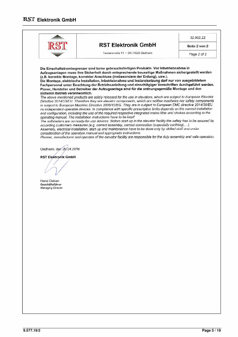
2 EU declaration of conformity
Elektronik GmbH
9.577.19/2 Page 5 / 19
Elektronik GmbH
9.577.19/2 Page 6 / 19
3 Technical Data
3.1 Electrical Data
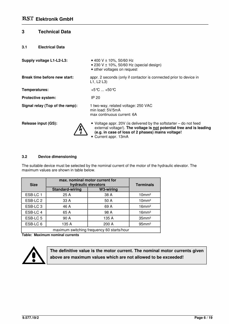
Supply voltage L1-L2-L3: ���� 400 V ± 10%, 50/60 Hz ���� 230 V ± 10%, 50/60 Hz (special design) ���� other voltages on request Break time before new start: appr. 2 seconds (only if contactor is connected prior to device in
L1, L2 L3) Temperatures: +5°C ... +50°C Protective system: IP 20 Signal relay (Top of the ramp): 1 two-way, related voltage: 250 VAC min load: 5V/5mA max continuous current: 6A Release input (GS): ���� Voltage appr. 20V (is delivered by the softstarter – do not feed external voltage!). The voltage is not potential free and is leading (e.g. in case of loss of 2 phases) mains voltage! ���� Current appr. 13mA
3.2 Device dimensioning
The suitable device must be selected by the nominal current of the motor of the hydraulic elevator. The maximum values are shown in table below.
Size max. nominal motor current for
hydraulic elevators Terminals Standard-wiring W3-wiring
ESB-LC 1 25 A 38 A 10mm²
ESB-LC 2 33 A 50 A 10mm²
ESB-LC 3 46 A 69 A 16mm²
ESB-LC 4 65 A 98 A 16mm²
ESB-LC 5 90 A 135 A 35mm²
ESB-LC 6 135 A 200 A 95mm²
maximum switching frequency 60 starts/hour Table: Maximum nominal currents
The definitive value is the motor current. The nominal motor currents given
above are maximum values which are not allowed to be exceeded!

Elektronik GmbH
9.577.19/2 Page 7 / 19
3.3 Three-phase choke
While starting the device produces radio disturbances and low-frequency harmonics because of phase-shifting operation. These will be effectively reduce by a 3-phase choke in the power supply line. The suitable 3-phase choke must always be selected according to the nominal current of the motor. The maximum nominal motor currents are shown in table below.
Table: three-phase chokes
3.4 Inrush current factor
The factor between "limited" inrush current and nominal motor current may be between 1,0 and 2,0 if the device is adjusted well. This value is very strong depending on the motor and the adjustment of the ESB-LC: The ESB-LC raises the voltage linear. The current is not measured and controlled. The reduction of the current appears because of physical fundamental laws. A short start-up time causes high inrush currents. An extreme false adjustment (Time = min and Offset = max) causes nearly the same inrush current as switching on the motor directly. For this reason a concrete factor for the limited inrush current can not be given.
4 Mechanical data
4.1 Dimensions and weights
Table: Dimensions and weights
4.2 Device fixing
The devices ESB-LC 1...5 will be mounted with 3 internal wrenching bolts. The device ESB-LC 6 will be mounted with 4 bolts.
type nominal current ESB-KDR-1 max. 25 A ESB-KDR-2 max. 38 A ESB-KDR-3 max. 50 A ESB-KDR-4 max. 69 A ESB-KDR-5 max. 98 A ESB-KDR-6 max. 135 A ESB-KDR-7 max. 155 A
Size Width Height Depth Weight ESB-LC 1 200 mm 230 mm 115 mm ca. 2,6 kg ESB-LC 2 200 mm 230 mm 115 mm ca. 2,6 kg ESB-LC 3 200 mm 230 mm 130 mm ca. 3,8 kg ESB-LC 4 216 mm 230 mm 173 mm ca. 5,9 kg ESB-LC 5 216 mm 230 mm 173 mm ca. 7,3 kg ESB-LC 6 380 mm 400 mm 210 mm ca. 19,2 kg

Elektronik GmbH
9.577.19/2 Page 8 / 19
5 General description
5.1 Basics
If a non-synchronous machine is switching on directly or by star-delta-switching, mains fluctuations are caused. The current pulse while the start-up time causes short lows and breakings in the mains-network (some milli-seconds). The consequences are more or less heavy interferences to other consumers, for example disturbances in radios and TV’s, light flickers, data missing in computers or unintended events in electronic appliances. To get rid of this problem you can use a soft start device. The aim is to decrease the start-up current considerable and to improve the behaviour and lifetime of the elevator-system. With the "ESB-LC" the voltage at the non-synchronous machine is driven up to nominal voltage within an adjustable time. The motor is always delta-connected, the torque builds up steadily. The motor starts slowly and accelerates softly.
5.2 Applications
The devices of the series "ESB-LC" may be used for hydraulic elevators to lift directive.
5.3 Advantages
The "ESB-LC" has following additional advantages: • Compact dimensions and low-space requirement through microprocessor controlling. • Simple connection into the motor feed line (standard-wiring). • The motor starts automatically if the three-phase line voltage is applied. You may also or additional start
the motor with an external release contact connected to the "ESB-LC". • The motor voltage increases during the start-up phase to 100%. The start-up time and start-voltage are
adjustable with potentiometers. • Signal emission (relay point, top of the ramp) if the full voltage is achieved. With this relay external loads
(e.g. valves) may be switched. • Simple installation and commissioning without any problems.
5.4 Construction
The "ESB-LC" is constructed with a power part and an electronic board. The power part exists of a power heat sink with thyristors, which are building a fully controlled three-phase thyristor regulator. The electronic board, also containing the internal supply for pulse-firing, is mounted directly on the thyristors. At the front of the electronic board there is a two-pole and three-pole terminal. You can connect an external release signal (potential free contact) at the two-pole terminal "GS" (GS1 and GS2). The three-pole terminal (11, 12, and 14) leads the contacts of the signal-relay away.
Elektronik GmbH
9.577.19/2 Page 9 / 19
L3
L1
L2
ESB116-01.skd
L3
L2
L1
ESB116-01.skd
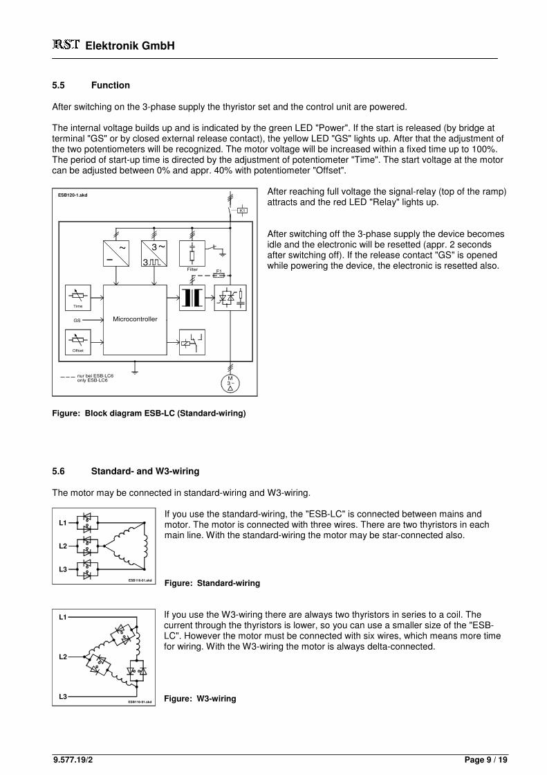
5.5 Function
After switching on the 3-phase supply the thyristor set and the control unit are powered. The internal voltage builds up and is indicated by the green LED "Power". If the start is released (by bridge at terminal "GS" or by closed external release contact), the yellow LED "GS" lights up. After that the adjustment of the two potentiometers will be recognized. The motor voltage will be increased within a fixed time up to 100%. The period of start-up time is directed by the adjustment of potentiometer "Time". The start voltage at the motor can be adjusted between 0% and appr. 40% with potentiometer "Offset".
After reaching full voltage the signal-relay (top of the ramp) attracts and the red LED "Relay" lights up. After switching off the 3-phase supply the device becomes idle and the electronic will be resetted (appr. 2 seconds after switching off). If the release contact "GS" is opened while powering the device, the electronic is resetted also.
Figure: Block diagram ESB-LC (Standard-wiring)
5.6 Standard- and W3-wiring
The motor may be connected in standard-wiring and W3-wiring. If you use the standard-wiring, the "ESB-LC" is connected between mains and motor. The motor is connected with three wires. There are two thyristors in each main line. With the standard-wiring the motor may be star-connected also. Figure: Standard-wiring
If you use the W3-wiring there are always two thyristors in series to a coil. The current through the thyristors is lower, so you can use a smaller size of the "ESB-LC". However the motor must be connected with six wires, which means more time for wiring. With the W3-wiring the motor is always delta-connected. Figure: W3-wiring
Microcontroller
Offset
nur bei ESB-LC6only ESB-LC6
Time
ESB120-1.skd
GS
~3
M3 ~
3~
Filter F1
K1

Elektronik GmbH
9.577.19/2 Page 10 / 19
a
d
Kühlkörperheat sink
L1 L2ES
B1
22-1
.skd L2L1
g
c
L3 WU V
b
e f
g
L3 WU V
g
6 Installation
6.1 General information
The power converters have to be protected from excessive stain. Above all, during transport and handling it is not allowed to bend any components nor it is allowed to alter any insulation spaces. The electronic components and contacts must not be touched.
Power converters contain electrostatically endangered components, which may easily be damaged by improper handling. People who work at these units must discharge themselves by touching an earthed object.
Electrical components must not be damaged or broken mechanically (possible damage to health). While working on charged power converters the valid national regulations for accident preventions have to be kept (e.g. VGB4). The electrical installation has to be carried out according to the relevant regulations (e.g. lead cross sections, protections, earth wiring). The installer of the elevator is responsible for the keeping of the limiting values required by the EMC-regulations.
6.2 Fitting
The device must be mounted vertically (that means, the rips of the heat sink should stand vertically), to ensure optimal heat removal. For better ventilation of the power unit it is necessary to keep a gap of at least 5 cm above and below the device.
6.2.1 Fixing holes ESB-LC 1...5
The devices ESB-LC 1...5 will be mounted in the control cabinet with 3 internal wrenching bolts. If you want to use a common assembly plate for ESB-LC 1...5 in the control cabinet, you may make the threads like on drawing number 5.199.xx (see appendix in the manual). Figure: Mechanical dimensions ESB-LC1…5
Table: fixing holes ESB-LC 1…5 (all dimensions in mm)
Size a b c d e f g Height of the heat sink ESB-LC 1 200 230 20,0 160 50 170 Ø 7 25 ESB-LC 2 200 230 20,0 160 50 170 Ø 7 25 ESB-LC 3 200 230 20,0 160 50 170 Ø 7 40 ESB-LC 4 216 230 36,5 143 50 170 Ø 7 83 ESB-LC 5 216 230 36,5 156 60 160 Ø 7 83

Elektronik GmbH
9.577.19/2 Page 11 / 19
6.2.2 Fixing holes ESB-LC 6
Table: Mechanical dimensions ESB-LC-6 Figure: fixing holes ESB-LC-6
Size a b c d e ESB-LC 6 380 400 340 360 9 c
a
e
ES
B1
23
-1.s
kd
L1 L2 U
L1 L2 U
e
4.105.xx
d
b
V
V
W L3
W L3
GS1 GS2141112
GS1 GS2141112
e
Filter off
14
Relay
Time
Offset
1
11
12
2GS
GS
X1
Power
1
Filter on
2
e

Elektronik GmbH
9.577.19/2 Page 12 / 19
Litzen vom Melderelaisflexible wires from the signal relay(Top of the ramp)
Litzen zu externem Kontakt (Startsignal)flexible wires to external contact (start signal)
2
1
12
11
14
ES
B1
05
-1.s
kd
GS
L2L1 L3
L2L1 L3
Schraube M5screw M5
WU V
WU V
ESB-LC
Dreiphasen-Kom-mutierungsdrossel3-phase choke
PE L2
F2
L1
F1
L3
F3
PE
K1
K2
L2L1 L3
Start beim Anlegen von L1, L2, L3Start when introducing L1, L2, L3
ESB102-1.skd
Öffnen = Stop Open = StopSchließen = Start Close = Start
M3~
Start-signal
U V WKontakte desMelderelais
contacts of thesignal relay
(Top of the ramp)
BrückeBridge
12GS
1
GS
2
14 11
6.3 Connection
The mains line must be connected with the terminals L1, L2 ,L3. The protective earth (PE) must be connected with the M5 earth screw or the PE-terminal. The contacts of the signal relay may be connected at the three-pole connection at the front of the PCB to switch external loads (e. g. valves). If necessary, the device may additionally be released with an external switch (potential free), which is connected to the two-pole connection "GS" at the front of the PCB. If connecting the switch, the bridge must be removed.
6.3.1 Advices for wiring ESB-LC 1...5
The flexible wires for connecting the pcb-terminals (GS1, GS2, 11, 12, and 14) have to be led out of the device above the left end bracket. Figure: cable running
6.3.2 Connection in standard-wiring
Figure 6.3.2-1 shows the principal order of the device in an elevator system with two contactors. It is also possible to wire one or all two contactors between terminal U, V, W and the motor. If doing this, the secondary contact (closing contact) of the respective contactor should be wired in series in the release line (GS1 - GS2). Firgure: Wiring diagram standard-wiring
Elektronik GmbH
9.577.19/2 Page 13 / 19
ESB-LC
Dreiphasen-Kom-mutierungsdrossel3-phase choke
U2
U1
PE
F2
L2
F1
L1
K1
L3
F3
PE
K2
L2L1 L3
Start beim Anlegen von L1, L2, L3Start when introducing L1, L2, L3
ESB103-1.skd
Öffnen = Stop Open = StopSchließen = Start Close = Start
W2
W1
M3~
V2
V1
Start-signal
U V WKontakte desMelderelais
contacts of thesignal relay
(Top of the ramp)
BrückeBridge
12GS
1
14 11GS
2
ESB-LC
Dreiphasen-Kom-mutierungsdrossel3-phase choke
U2
U1
L2
F2
PE
F1
L1 L3
F3
PE
K1
K2
L2L1 L3
Öffnen = Stop Open = StopSchließen = Start Close = Start
ESB104-1.skd
W2
W1
M3~
V2
V1
K2
Start-signal
K1
U V WKontakte desMelderelais
contacts of thesignal relay
(Top of the ramp)
12
GS
1
14
11
GS
2
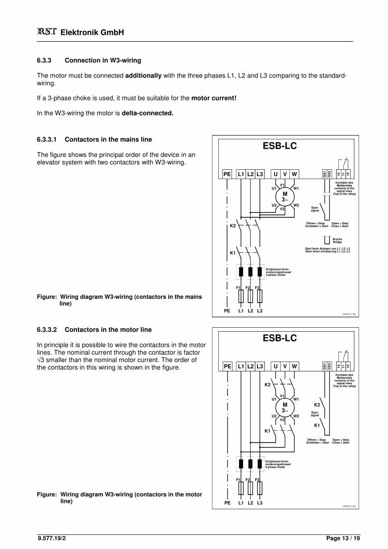
6.3.3 Connection in W3-wiring
The motor must be connected additionally with the three phases L1, L2 and L3 comparing to the standard-wiring. If a 3-phase choke is used, it must be suitable for the motor current! In the W3-wiring the motor is delta-connected.
6.3.3.1 Contactors in the mains line
The figure shows the principal order of the device in an elevator system with two contactors with W3-wiring. Figure: Wiring diagram W3-wiring (contactors in the mains
line)
6.3.3.2 Contactors in the motor line
In principle it is possible to wire the contactors in the motor lines. The nominal current through the contactor is factor √3 smaller than the nominal motor current. The order of the contactors in this wiring is shown in the figure. Figure: Wiring diagram W3-wiring (contactors in the motor
line)

Elektronik GmbH
9.577.19/2 Page 14 / 19
Filter on
Filter off
1 2
ES
B117-1
.skd
7 Commissioning instruction
7.1 Safety instructions
Units with build-in power converters eventually must be equipped with additional operational monitoring systems and protective gear according to the newest valid safety regulations, e.g. law of technical work material, regulations of accident prevention etc. After separating the power converters from the distribution voltage, power leading components and terminals must not immediately be touched because of possibly charged condensators. During operation all coverings and doors have to be closed.
7.2 General information
The device is pre-adjusted by the manufacturer, so that the motor can be started immediately if all connections are made. If the power is introduced, the internal power is indicated with the green LED "Power" on the PCB. The yellow LED "GS" lights up, if the start-input is bridged or the external switch is closed. If adjusted by the manufacturer (Time = max , Offset = min) the voltage at the motor rises from 0% up to 100% within appr. 5 seconds. After reaching full voltage the signal relay on the PCB attracts and the red LED "Relais" lights up.
7.3 Operating with FI switch
The softstarter ESB-LC has RC-components against earth to reduce disturbances (EMC). The static divert current is about 5 mA. During the switch-on time or if having unsymmetrical mains, this current may be bigger, so that a fault current protection switch with 30 mA threshold current can be released. Solutions: a) Use a special FI switch for electronic drives with higher threshold release (e.g. from Siemens). b) The connection from the filter to protective earth (PE) is conducted above a PCB terminal.
If you have problems with a FI switch, especially if supplied from a building site main cabinet, the bridge in the PCB terminal may be momentary removed (see figure). After normal supply the bridge must be put in to fulfil the EMC-regulations.
Elektronik GmbH
9.577.19/2 Page 15 / 19
Prüfstecker: Kontakte nicht brücken!Test plug: don´t bridge the contacts!
Relay2GS
ESB101-01.skd1
12
14
11
Offset
GS
X1
Power
Filter onTime
4.097.xx
Prüfstecker: Kontakte nicht brücken!Test plug: don´t bridge the contacts!
4.105.xxESB117-1.skd
GS
14
11
12 1 2
RelayGS
Power
Filter on
Filter off
1 2
X1
Time
Offset
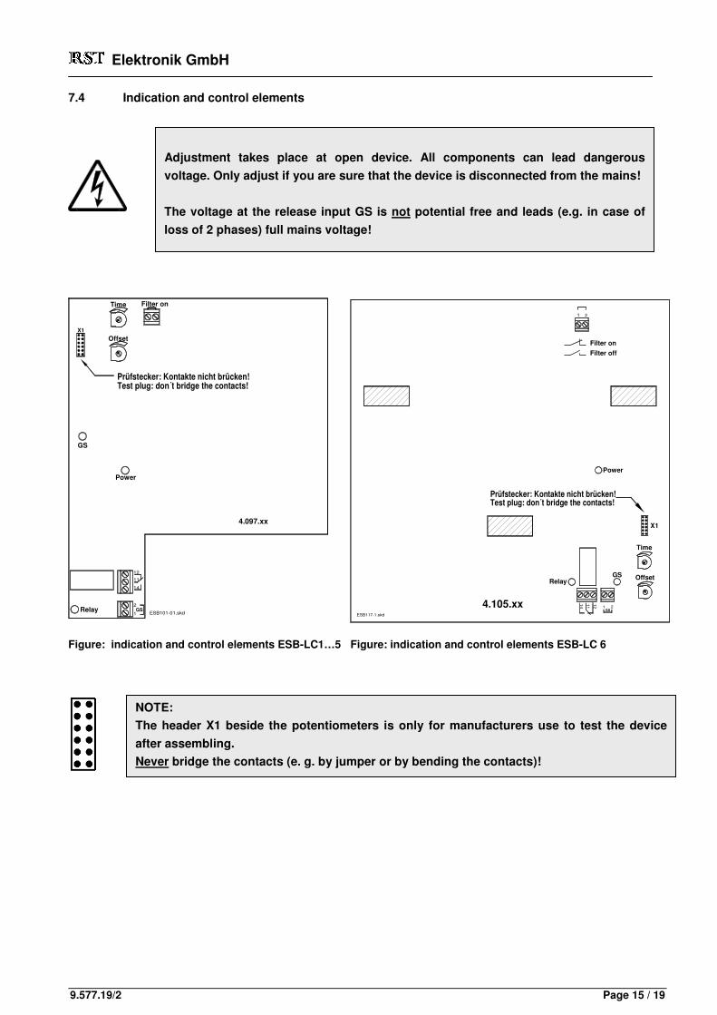
7.4 Indication and control elements
Figure: indication and control elements ESB-LC1…5 Figure: indication and control elements ESB-LC 6
Adjustment takes place at open device. All components can lead dangerous
voltage. Only adjust if you are sure that the device is disconnected from the mains!
The voltage at the release input GS is not potential free and leads (e.g. in case of
loss of 2 phases) full mains voltage!
NOTE:
The header X1 beside the potentiometers is only for manufacturers use to test the device
after assembling.
Never bridge the contacts (e. g. by jumper or by bending the contacts)!
Elektronik GmbH
9.577.19/2 Page 16 / 19
max
u
U
Offset = min
t
Offset = max
ESB100-1.skd
u
maxU
Time = min
Time = max
t
ESB100-1.skd
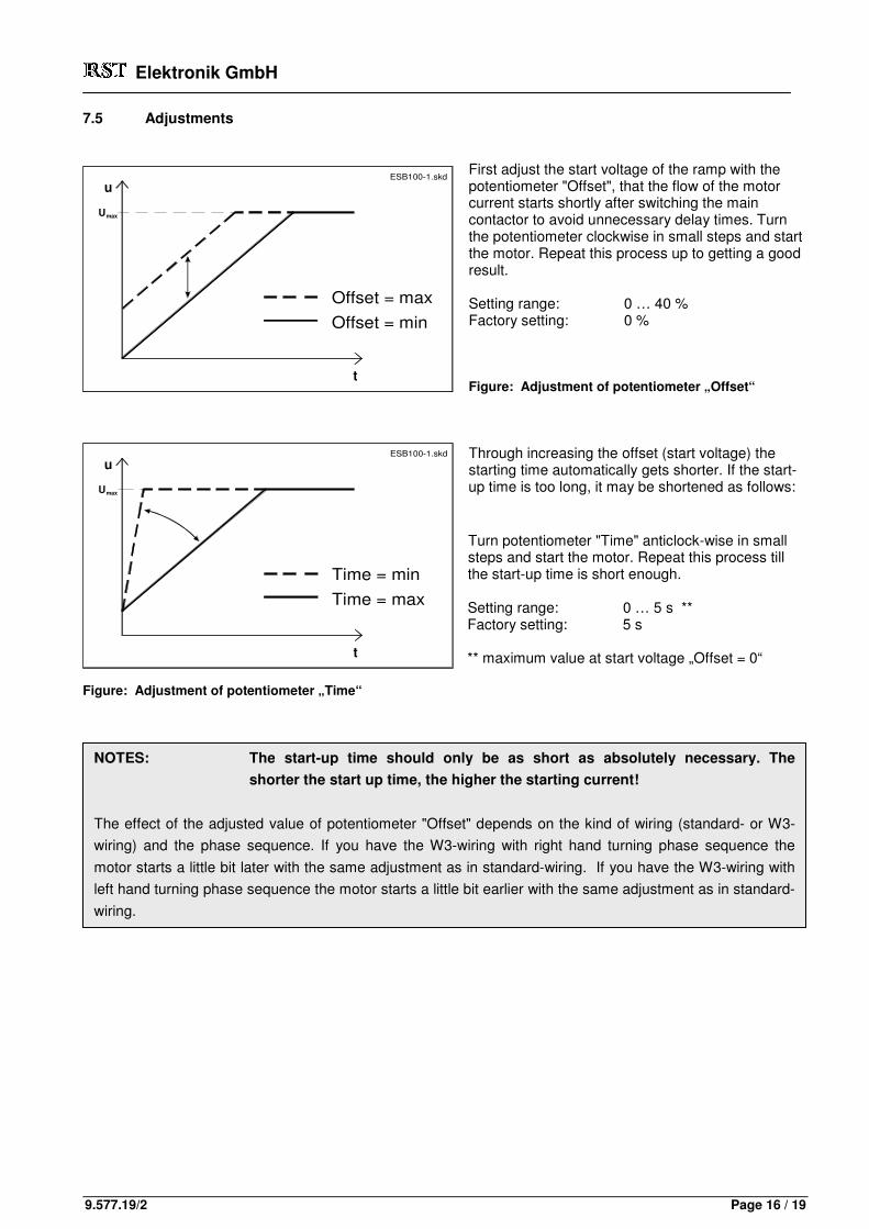
7.5 Adjustments
First adjust the start voltage of the ramp with the potentiometer "Offset", that the flow of the motor current starts shortly after switching the main contactor to avoid unnecessary delay times. Turn the potentiometer clockwise in small steps and start the motor. Repeat this process up to getting a good result. Setting range: 0 … 40 % Factory setting: 0 % Figure: Adjustment of potentiometer „Offset“
Through increasing the offset (start voltage) the starting time automatically gets shorter. If the start-up time is too long, it may be shortened as follows: Turn potentiometer "Time" anticlock-wise in small steps and start the motor. Repeat this process till the start-up time is short enough. Setting range: 0 … 5 s ** Factory setting: 5 s ** maximum value at start voltage „Offset = 0“
Figure: Adjustment of potentiometer „Time“
NOTES: The start-up time should only be as short as absolutely necessary. The
shorter the start up time, the higher the starting current!
The effect of the adjusted value of potentiometer "Offset" depends on the kind of wiring (standard- or W3-
wiring) and the phase sequence. If you have the W3-wiring with right hand turning phase sequence the
motor starts a little bit later with the same adjustment as in standard-wiring. If you have the W3-wiring with
left hand turning phase sequence the motor starts a little bit earlier with the same adjustment as in standard-
wiring.

Elektronik GmbH
9.577.19/2 Page 17 / 19
8 Description of errors
Effect Cause Removal
Motor does not run
One or more phases are missing Check fuses Check wiring
Drive contactor doesn’t attract Check wiring LED „Power“ doesn’t light up Check wiring
LED of the start signal (GS) doesn’t light up
Close external release switch respectively connect bridge at terminal „GS“
Motor hums, but motor does not run
Wrong wiring (W3 wiring) Check wiring
Tug at starting (not at adjustment “Time = max” and “Offset = min”)
Wrong adjustment of potentiometer „Offset“ and/or „Time“
Adjust potentiometers new
Start up time is too short or too long
Wrong adjustment of potentiometer „Offset“ and/or „Time”
Adjust potentiometers new
FI switch wired prior the device releases
Divert current from the EMC-filter See chapter “FI switch”
Direction of the rotation of the motor is wrong
---
Standard wiring: Change 2 phases in mains line or motor line W3 wiring: Change 2 phases in mains line (before the junction of the wires going to the motor!)
Table: Effect of error and removal
9 Maintenance
As the modern electronically construction components are very durable and are naturally not subject to any mechanical wear and tear, normally no special service and maintenance will be necessary to be carried out on the device. Within general service of the elevators, however, some things should be checked: a) Heat sink of the ESB-LC:
It has to be taken care of the rips of the heat sink being not congested by dust accumulations. In general
residential and office buildings problems like this don't occur as a rule.
b) PCB of the ESB-LC:
With a dirty and dusty environment, especially with industrial elevators e.g. within the range of chemical and
similar industries, possible dust accumulations on the PCB and in the power components have to be blown off
occasionally in order to avoid tracking currents and flashovers.
The relay contact points from the signal relay must be checked for consumption.
The flexible wires connected with the PCB-terminals (GS1, GS2, 11, 12, 14) must be checked for their fitting.
c) Power Unit:
The power terminals must be checked for their fitting.
���� ���� ���� ���� Subject to change without prior notice ���� ���� ���� ����

Elektronik GmbH
9.577.19/2 Page 18 / 19
10 Appendix
10.1 Dimensions of 3-phase choke
Tannenstr.11 D-74229 Oedheim
c
Werte auf Anfrage / values on request
*) Maximalwerte, genauer Wert abhängig vom Drosselhersteller*) maximum values, exact value depending on the producer of the choke
Abmessungen in mmdimensions in mm
Freigabe
05.05.97
13.08.93
max. 25,0 A
max. 37,5 A
max. 49,5 A
max. 135,0 A
max. 155,0 A
max. 98,0 A
max. 69,0 A
Nominal motor-current
Motor-Nennstrom
ESB-KDR
ESB-KDR-7
Index41424344
Änd.Nr.Rev.
1653
Type
ESB-KDR-1
ESB-KDR-2
ESB-KDR-3
ESB-KDR-4
ESB-KDR-5
ESB-KDR-6
Typ
Bearb.Gepr.Norm
Name
MüllerKieweg
10.04.02Datum
10 mm²
10 mm²
16 mm²
35 mm²
70 mm²
35 mm²
Terminals
Klemmen
120
190
190
150
121
120
a*)
d
a
f
W1
W2
V1
V2
U2
PE
U1
Abmessungen Kommutierungsdrossel
dimensions 3-phase choke
5.213.44
7,5
7,5
5,7
4,5
4,5
4,5
Zchngs.-Nr.:
JanzName
Maßstab
165 78
245
230
210
165
137
115
106
91
165 81
c*)
b*)
39 90
76
58
65
49
170
170
113
90
38 90
ed
Datei:5-213-44.skd
1 Bl.
Blatt 1
10,0 kg
Weight (appr.)
Gewicht (ca.)
8,5
11,5
11,5
11,0
8,5
8,5
gf
2,5 kg
3,2 kg
5,7 kg
7,0 kg
2,2 kg
b
e
g
Elektronik GmbH
9.577.19/2 Page 19 / 19
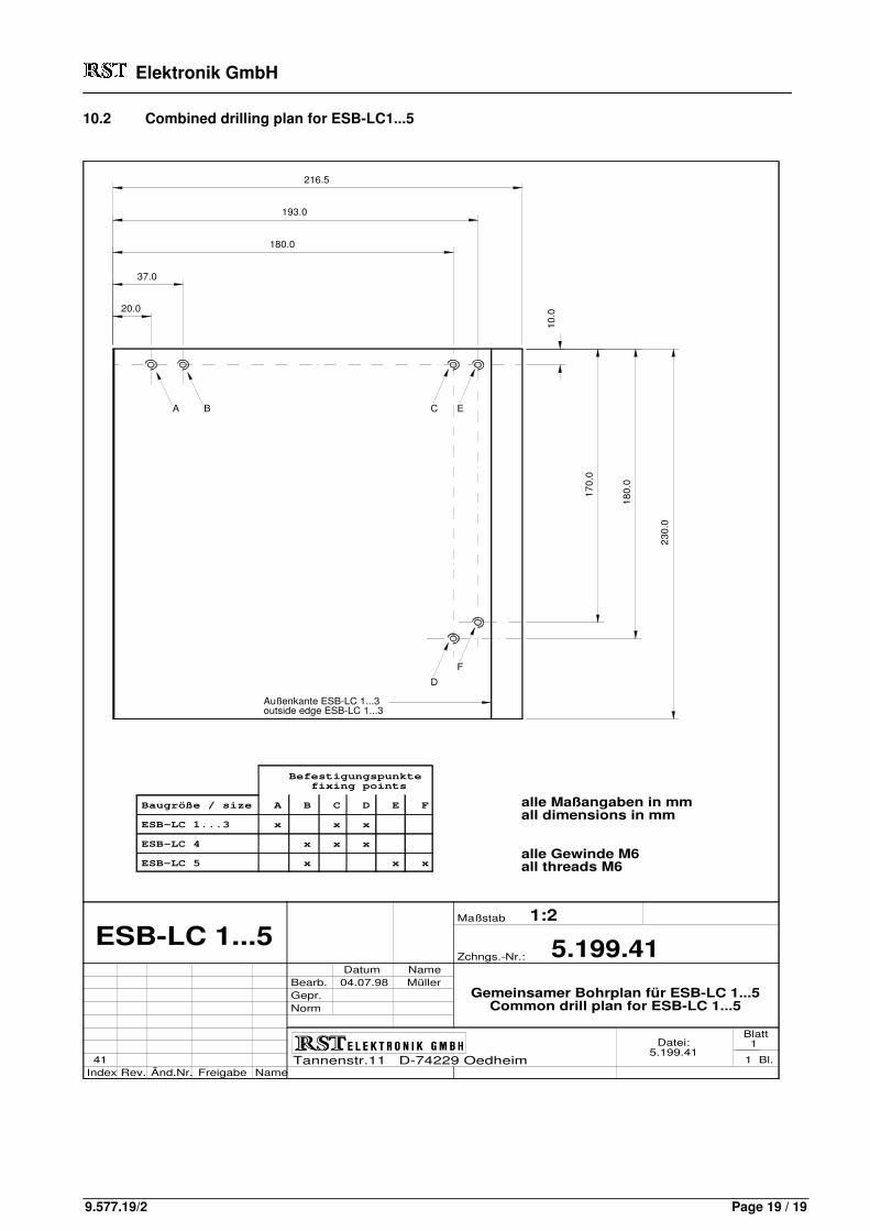
10.2 Combined drilling plan for ESB-LC1...5
Tannenstr.11 D-74229 Oedheim
180.0
193.0
216.5
Außenkante ESB-LC 1...3outside edge ESB-LC 1...3
Befestigungspunkte fixing points
Baugröße / size A B C D E F
ESB-LC 1...3 x x x
ESB-LC 4 x x x
ESB-LC 5 x x x
Freigabe
ESB-LC 1...5
Index41
Änd.Nr.Rev.
Bearb.Gepr.Norm
Name
04.07.98Datum
B A
20.0
37.0
17
0.0
18
0.0
23
0.0
5.199.41
Gemeinsamer Bohrplan für ESB-LC 1...5Common drill plan for ESB-LC 1...5
alle Maßangaben in mmall dimensions in mm
alle Gewinde M6all threads M6
Zchngs.-Nr.:
Müller
Maßstab
Name
1:2
F
D
Datei:5.199.41
1 Bl.
Blatt 1
C E
10
.0