esp-lx modular controller installation, programming ... · esp-lx modular controller 7 basic...
TRANSCRIPT

ESP-LX Modular Controller Installation, Programming,
& Operation Guide
SAFETY INFORMATION WARNING: A CIRCUIT BREAKER OR CUTOFF SWITCH IS TO BE PROVIDED IN THE FIXED WIRING TO ISOLATE THE CONTROLLER.
MEMORY IS RETAINED BY A BATTERY, WHICH IS TO BE DISPOSED OF IN ACCORDANCE WITH LOCAL REGULATIONS.
The lightning flash with arrowhead symbol, within an equilateral triangle, is intended to alert the user to the presence of uninsulated “dangerous voltage” within the product’s enclosure that may be of sufficient magnitude to constitute a risk of electronic shock to persons.
The exclamation point within an equilateral triangle is intended to alert the user to the presence of important operating and maintenance (servicing) instructions in the literature accompanying the product.
ATTENTION: UN DISJONCTEUR OU UN INTERRUPTEUR DOIT ETRE INSTALLE SUR LE PRIMAIRE POUR ISOLER LE PROGRAMMATEUR.
LA MEMOIRE EST MAINTENUE GRACE A UNE BATTERIE RECHARGEABLE A DISPOSER SELON LA REGLEMENTATION LOCALE.
L’éclair avec le symbole de la flèche, placé dans les limites d’un triangle èquilatéral est prévu pour avertir l’utilisateur de la présence de “tension dangereuse” non isolé dans l’enceinte du produit qui pourrait ëtre d’une importance suffisante pour présenter un risque d’èlectrocution aux personnes.
Le point d’exclamation dans un triangle èquilatéral est prévu pour avertir l’utilisateur de la présence d’instructions importantes pour les opérations et l’entretien (service) dans les manuels fournis avec l’appareil.
ESP-LX Modular Controller 1
CONTENTS Introduction ..............................................................................3
Welcome to Rain Bird........................................................... 3 ESP-LX Modular Controller ................................................. 3
Valves ........................................................................... 4 Basic Operation............................................................. 5
Controls, Switches, and Indicators ........................................ 6 Basic Programming ...................................................................7
Definitions............................................................................. 7 Programming Under Battery Power ...................................... 8 Programming Checklist......................................................... 9 Fill Out Programming Chart ............................................... 10
Sample Programming Chart ........................................ 11 Clear Programs.................................................................... 12
Individual Program...................................................... 12 All Programs ............................................................... 13 Restore Defaults .......................................................... 14
Set Date............................................................................... 15 Set Time.............................................................................. 16 Select Program .................................................................... 17 Set Watering Start Times .................................................... 18 Select Days to Water........................................................... 19
Custom Cycle .............................................................. 20 Odd/Odd31/Even Cycle .............................................. 21 Cyclical ....................................................................... 22
Set Valve Run Times .......................................................... 24 Advanced Programming...........................................................25
Seasonal Adjust % .............................................................. 25 Individual Program...................................................... 26
By Month.....................................................................27 Delay Watering....................................................................30
Rain Delay ...................................................................30 Calendar Day Off.........................................................31
Valve Settings......................................................................33 Valve Delay .................................................................33 Cycle+Soak™..............................................................35 MV or Pump ................................................................37 Sensor Override ...........................................................38
Special Features...................................................................40 Set Language ...............................................................40 Backup Programs — Contractor Default™ .................41
Optional Smart Modules™..................................................45 Communications..................................................................45 Set Sensor Bypass Switch....................................................45
Operating the Controller ......................................................... 48 Operate Controller Automatically........................................48 Manual Watering .................................................................50
Start Valve ...................................................................50 Start Program...............................................................52
Test All Valves/Check System ............................................54 Confirm Programs .......................................................54 Test All Valves ............................................................60
Rapid Station Test Routine — RASTER™ .........................63 Reset Controller ...................................................................65 Alarm Light .........................................................................66
Electrical Faults ...........................................................66 Active Sensor...............................................................66
2 ESP-LX Modular Controller
Installing the Controller ..........................................................67 Installation Checklist ...........................................................67 Check Box Contents ............................................................67 Choose Location ..................................................................68 Gather Installation Tools .....................................................69 Mount Controller .................................................................70 Install Module(s)..................................................................72 Connect Field Wiring ..........................................................73 Connect Sensor Wiring........................................................74 Connect Source Power.........................................................75 Complete Installation...........................................................78
Troubleshooting Chart.............................................................79 Index .......................................................................................82
ESP-LX Modular Controller 3
INTRODUCTION
Welcome to Rain Bird Thank you for purchasing your new state-of-the-art Rain Bird ESP-LX Modular controller. For more than six decades, Rain Bird has led the irrigation industry in meeting all of your water management needs by providing the highest quality products and services available. Your new Rain Bird controller is designed to give you a lifetime of on-site watering control.
ESP-LX Modular Controller The ESP-LX Modular controller is an irrigation timing system designed for commercial and residential use. The controller’s modular design can accommodate from 8 to 32 valves.
The ESP-LX Modular controller is available in an indoor-only version, as well as an indoor/outdoor version. The controller includes many advanced features to help you manage water efficiently. These include: Programmable valve delay Cycle+Soak™ Sensor connection with bypass switch Built-in diagnostic and validation software Compatibility with all Rain Bird remote systems, including
one-button and multi-function systems
4 ESP-LX Modular Controller
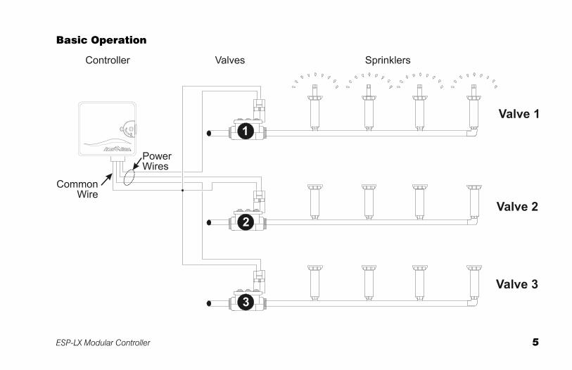
Valves The ESP-LX Modular controls when your sprinkler system turns on, and how long the sprinklers run. The controller has several valves connected to it, as shown in the illustration on the following page.
Each valve opens when it receives power from the controller, and the sprinklers connected to that valve turn on. When these sprinklers have run for their programmed time, the controller shuts off the valve and opens the next valve in sequence.
For example, the illustration on page 5 shows that valve 1 is currently watering. When valve 1 is finished, the controller will shut it off and start valve 2. In the same way, valve 3 will begin watering when valve 2 is finished.
NOTES: The ESP-LX Modular controller lets you set a delay between valves. (See page 33.) For example, if you set a one-minute delay, valve 1 will run until finished, followed by a one-minute delay. Then valve 2 will operate, followed by a one-minute delay.
In addition, the Cycle+Soak™ feature may delay valve operation. See page 35.
ESP-LX Modular Controller 5
Basic Operation
6 ESP-LX Modular Controller
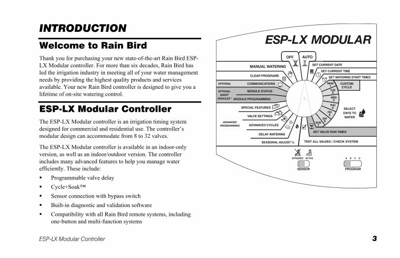
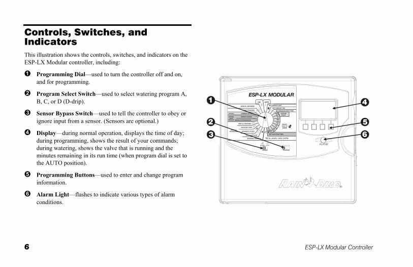
Controls, Switches, and Indicators This illustration shows the controls, switches, and indicators on the ESP-LX Modular controller, including:
Programming Dial—used to turn the controller off and on, and for programming.
Program Select Switch—used to select watering program A, B, C, or D (D-drip).
Sensor Bypass Switch—used to tell the controller to obey or ignore input from a sensor. (Sensors are optional.)
Display—during normal operation, displays the time of day; during programming, shows the result of your commands; during watering, shows the valve that is running and the minutes remaining in its run time (when program dial is set to the AUTO position).
Programming Buttons—used to enter and change program information.
Alarm Light—flashes to indicate various types of alarm conditions.
ESP-LX Modular Controller 7
BASIC PROGRAMMING
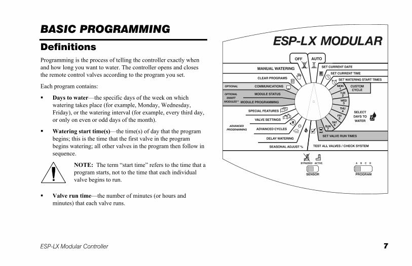
Definitions Programming is the process of telling the controller exactly when and how long you want to water. The controller opens and closes the remote control valves according to the program you set.
Each program contains:
Days to water—the specific days of the week on which watering takes place (for example, Monday, Wednesday, Friday), or the watering interval (for example, every third day, or only on even or odd days of the month).
Watering start time(s)—the time(s) of day that the program begins; this is the time that the first valve in the program begins watering; all other valves in the program then follow in sequence.
NOTE: The term “start time” refers to the time that a program starts, not to the time that each individual valve begins to run.
Valve run time—the number of minutes (or hours and minutes) that each valve runs.
8 ESP-LX Modular Controller
Programming Under Battery Power You can remove the front face panel of the controller and install a 9-Volt battery. You can then program the unit under battery power. This feature can be useful if the controller is installed in an area that is not readily accessible. This feature also lets you enter program information before installing the controller at the job site.
Although you can program the controller under battery power, you cannot operate it on battery power alone. Connect the controller to an AC power source as soon as possible.
NOTE: All program information is stored in non-volatile memory so it will be preserved indefinitely in the event of a power outage.
ESP-LX Modular Controller 9
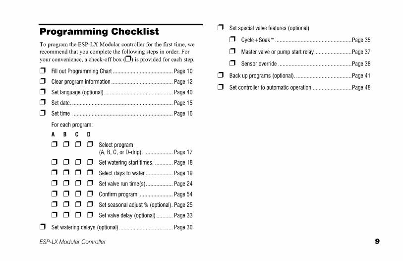
Programming Checklist To program the ESP-LX Modular controller for the first time, we recommend that you complete the following steps in order. For your convenience, a check-off box ( ) is provided for each step.
Fill out Programming Chart ........................................ Page 10
Clear program information ......................................... Page 12
Set language (optional).............................................. Page 40
Set date. ................................................................... Page 15
Set time . .................................................................. Page 16
For each program:
A B C D
Select program (A, B, C, or D-drip). ................... Page 17
Set watering start times. ............ Page 18
Select days to water .................. Page 19
Set valve run time(s).................. Page 24
Confirm program ....................... Page 54
Set seasonal adjust % (optional). Page 25
Set valve delay (optional) ........... Page 33
Set watering delays (optional).................................... Page 30
Set special valve features (optional)
Cycle+Soak™...................................................Page 35
Master valve or pump start relay.........................Page 37
Sensor override .................................................Page 38
Back up programs (optional). .....................................Page 41
Set controller to automatic operation...........................Page 48
10 ESP-LX Modular Controller
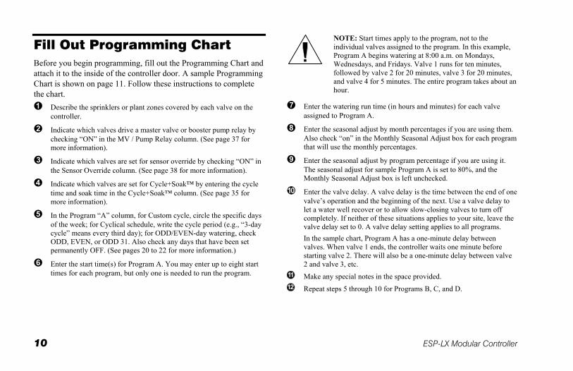
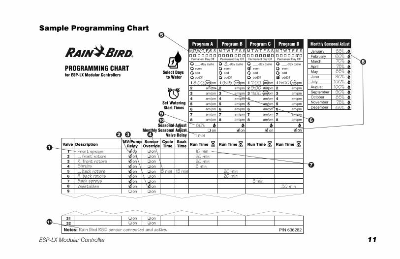
Fill Out Programming Chart Before you begin programming, fill out the Programming Chart and attach it to the inside of the controller door. A sample Programming Chart is shown on page 11. Follow these instructions to complete the chart.
Describe the sprinklers or plant zones covered by each valve on the controller.
Indicate which valves drive a master valve or booster pump relay by checking “ON” in the MV / Pump Relay column. (See page 37 for more information).
Indicate which valves are set for sensor override by checking “ON” in the Sensor Override column. (See page 38 for more information).
Indicate which valves are set for Cycle+Soak™ by entering the cycle time and soak time in the Cycle+Soak™ column. (See page 35 for more information).
In the Program “A” column, for Custom cycle, circle the specific days of the week; for Cyclical schedule, write the cycle period (e.g., “3-day cycle” means every third day); for ODD/EVEN-day watering, check ODD, EVEN, or ODD 31. Also check any days that have been set permanently OFF. (See pages 20 to 22 for more information.)
Enter the start time(s) for Program A. You may enter up to eight start times for each program, but only one is needed to run the program.
NOTE: Start times apply to the program, not to the individual valves assigned to the program. In this example, Program A begins watering at 8:00 a.m. on Mondays, Wednesdays, and Fridays. Valve 1 runs for ten minutes, followed by valve 2 for 20 minutes, valve 3 for 20 minutes, and valve 4 for 5 minutes. The entire program takes about an hour.
Enter the watering run time (in hours and minutes) for each valve assigned to Program A.
Enter the seasonal adjust by month percentages if you are using them. Also check “on” in the Monthly Seasonal Adjust box for each program that will use the monthly percentages.
Enter the seasonal adjust by program percentage if you are using it. The seasonal adjust for sample Program A is set to 80%, and the Monthly Seasonal Adjust box is left unchecked.
Enter the valve delay. A valve delay is the time between the end of one valve’s operation and the beginning of the next. Use a valve delay to let a water well recover or to allow slow-closing valves to turn off completely. If neither of these situations applies to your site, leave the valve delay set to 0. A valve delay setting applies to all programs.
In the sample chart, Program A has a one-minute delay between valves. When valve 1 ends, the controller waits one minute before starting valve 2. There will also be a one-minute delay between valve 2 and valve 3, etc.
Make any special notes in the space provided.
Repeat steps 5 through 10 for Programs B, C, and D.
ESP-LX Modular Controller 11
Sample Programming Chart
12 ESP-LX Modular Controller
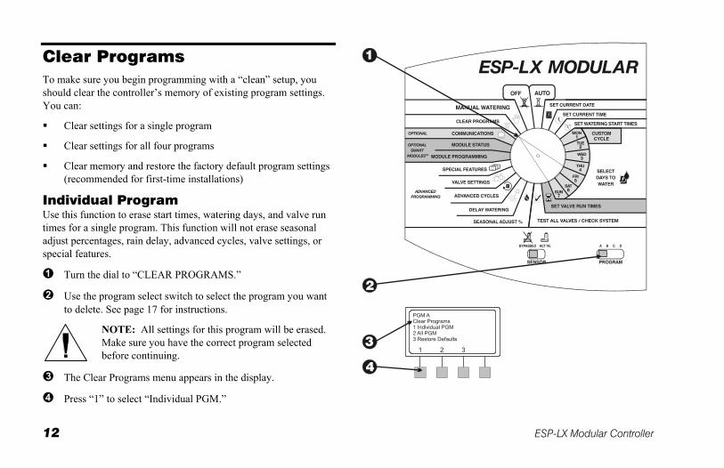
Clear Programs To make sure you begin programming with a “clean” setup, you should clear the controller’s memory of existing program settings. You can:
Clear settings for a single program
Clear settings for all four programs
Clear memory and restore the factory default program settings (recommended for first-time installations)
Individual Program Use this function to erase start times, watering days, and valve run times for a single program. This function will not erase seasonal adjust percentages, rain delay, advanced cycles, valve settings, or special features.
Turn the dial to “CLEAR PROGRAMS.”
Use the program select switch to select the program you want to delete. See page 17 for instructions.
NOTE: All settings for this program will be erased. Make sure you have the correct program selected before continuing.
The Clear Programs menu appears in the display.
Press “1” to select “Individual PGM.”
ESP-LX Modular Controller 13
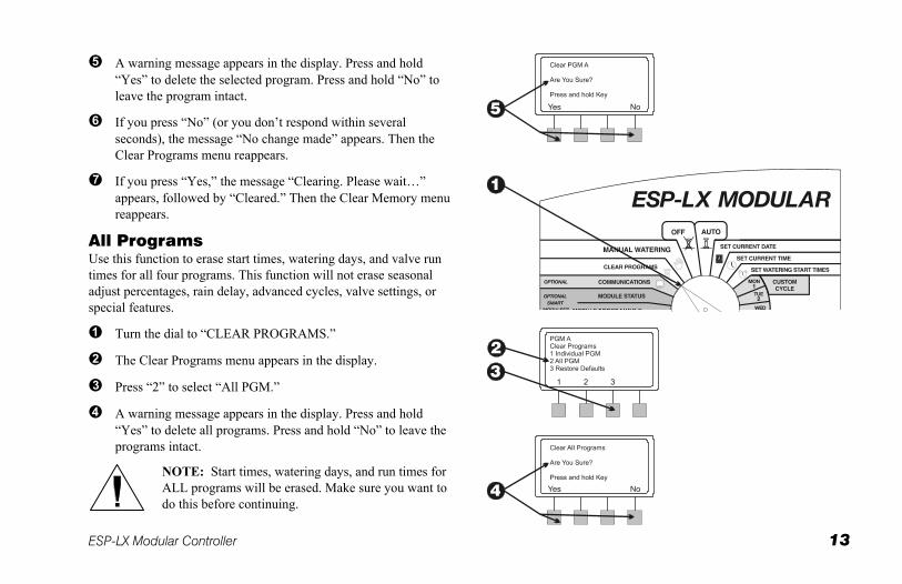
A warning message appears in the display. Press and hold “Yes” to delete the selected program. Press and hold “No” to leave the program intact.
If you press “No” (or you don’t respond within several seconds), the message “No change made” appears. Then the Clear Programs menu reappears.
If you press “Yes,” the message “Clearing. Please wait…” appears, followed by “Cleared.” Then the Clear Memory menu reappears.
All Programs Use this function to erase start times, watering days, and valve run times for all four programs. This function will not erase seasonal adjust percentages, rain delay, advanced cycles, valve settings, or special features.
Turn the dial to “CLEAR PROGRAMS.”
The Clear Programs menu appears in the display.
Press “2” to select “All PGM.”
A warning message appears in the display. Press and hold “Yes” to delete all programs. Press and hold “No” to leave the programs intact.
NOTE: Start times, watering days, and run times for ALL programs will be erased. Make sure you want to do this before continuing.
14 ESP-LX Modular Controller
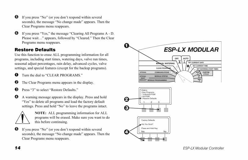
If you press “No” (or you don’t respond within several seconds), the message “No change made” appears. Then the Clear Programs menu reappears.
If you press “Yes,” the message “Clearing All Programs A - D. Please wait…” appears, followed by “Cleared.” Then the Clear Programs menu reappears.
Restore Defaults Use this function to erase ALL programming information for all programs, including start times, watering days, valve run times, seasonal adjust percentages, rain delay, advanced cycles, valve settings, and special features (except for the backup programs).
Turn the dial to “CLEAR PROGRAMS.”
The Clear Programs menu appears in the display.
Press “3” to select “Restore Defaults.”
A warning message appears in the display. Press and hold “Yes” to delete all programs and load the factory default settings. Press and hold “No” to leave the programs intact.
NOTE: ALL programming information for ALL programs will be erased. Make sure you want to do this before continuing.
If you press “No” (or you don’t respond within several seconds), the message “No change made” appears. Then the Clear Programs menu reappears.
ESP-LX Modular Controller 15
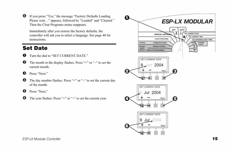
If you press “Yes,” the message “Factory Defaults Loading. Please wait…” appears, followed by “Loaded” and “Cleared.” Then the Clear Programs menu reappears.
Immediately after you restore the factory defaults, the controller will ask you to select a language. See page 40 for instructions.
Set Date Turn the dial to “SET CURRENT DATE.”
The month in the display flashes. Press “+” or “–“ to set the current month.
Press “Next.”
The day number flashes. Press “+” or “–“ to set the current day of the month.
Press “Next.”
The year flashes. Press “+” or “–“ to set the current year.
16 ESP-LX Modular Controller
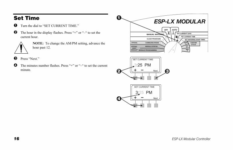
Set Time Turn the dial to “SET CURRENT TIME.”
The hour in the display flashes. Press “+” or “–“ to set the current hour.
NOTE: To change the AM/PM setting, advance the hour past 12.
Press “Next.”
The minutes number flashes. Press “+” or “–“ to set the current minute.
ESP-LX Modular Controller 17
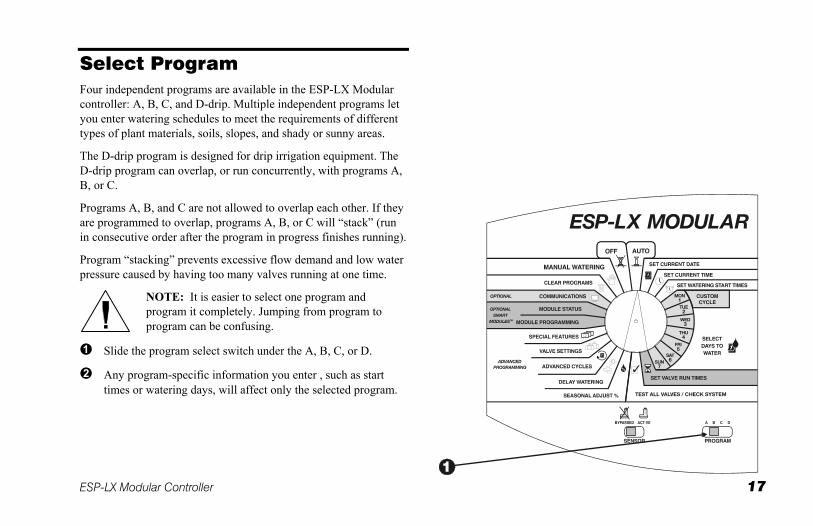
Select Program Four independent programs are available in the ESP-LX Modular controller: A, B, C, and D-drip. Multiple independent programs let you enter watering schedules to meet the requirements of different types of plant materials, soils, slopes, and shady or sunny areas.
The D-drip program is designed for drip irrigation equipment. The D-drip program can overlap, or run concurrently, with programs A, B, or C.
Programs A, B, and C are not allowed to overlap each other. If they are programmed to overlap, programs A, B, or C will “stack” (run in consecutive order after the program in progress finishes running).
Program “stacking” prevents excessive flow demand and low water pressure caused by having too many valves running at one time.
NOTE: It is easier to select one program and program it completely. Jumping from program to program can be confusing.
Slide the program select switch under the A, B, C, or D.
Any program-specific information you enter , such as start times or watering days, will affect only the selected program.
18 ESP-LX Modular Controller
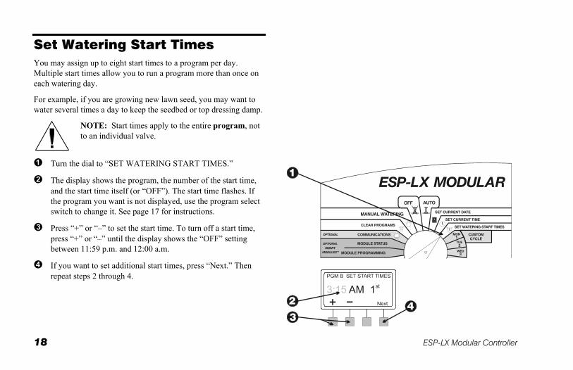
Set Watering Start Times You may assign up to eight start times to a program per day. Multiple start times allow you to run a program more than once on each watering day.
For example, if you are growing new lawn seed, you may want to water several times a day to keep the seedbed or top dressing damp.
NOTE: Start times apply to the entire program, not to an individual valve.
Turn the dial to “SET WATERING START TIMES.”
The display shows the program, the number of the start time, and the start time itself (or “OFF”). The start time flashes. If the program you want is not displayed, use the program select switch to change it. See page 17 for instructions.
Press “+” or “–” to set the start time. To turn off a start time, press “+” or “–” until the display shows the “OFF” setting between 11:59 p.m. and 12:00 a.m.
If you want to set additional start times, press “Next.” Then repeat steps 2 through 4.
ESP-LX Modular Controller 19
Select Days to Water Each program can operate in one of three watering day cycles:
1. CUSTOM waters on the days of the week you select. See the instructions on page 20.
NOTE: Any days you turn OFF via the Custom Cycle will override watering days set via advanced cycles, such as ODD/ODD31/ EVEN or CYCLICAL.
For example, assume you want a program to water on even days of the month, but you do not want to water on Wednesdays, when landscape service is scheduled. You can set the program to an EVEN cycle and use the CUSTOM cycle to turn Wednesdays off . The controller will then water on all even days of the month except Wednesdays.
2. ODD/ODD31/EVEN waters only on odd-numbered days, odd-numbered days except for the 31st and February 29th, or even-numbered days of the month. See page 21.
3. CYCLICAL waters on a selected daily interval (for example, every other day, or every third day). See page 22.
20 ESP-LX Modular Controller
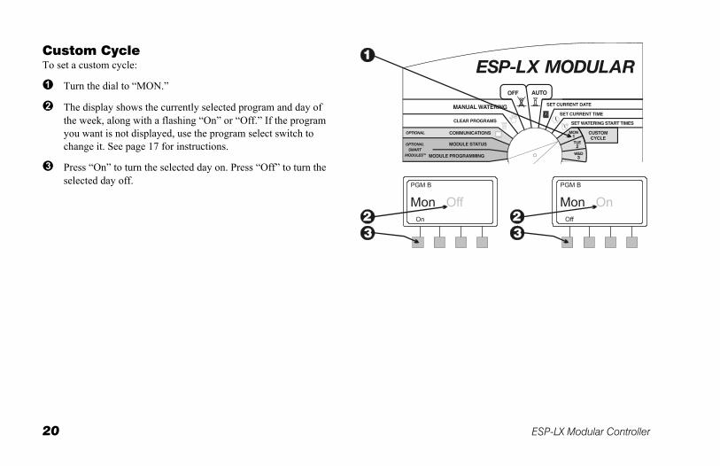
Custom Cycle To set a custom cycle:
Turn the dial to “MON.”
The display shows the currently selected program and day of the week, along with a flashing “On” or “Off.” If the program you want is not displayed, use the program select switch to change it. See page 17 for instructions.
Press “On” to turn the selected day on. Press “Off” to turn the selected day off.
ESP-LX Modular Controller 21
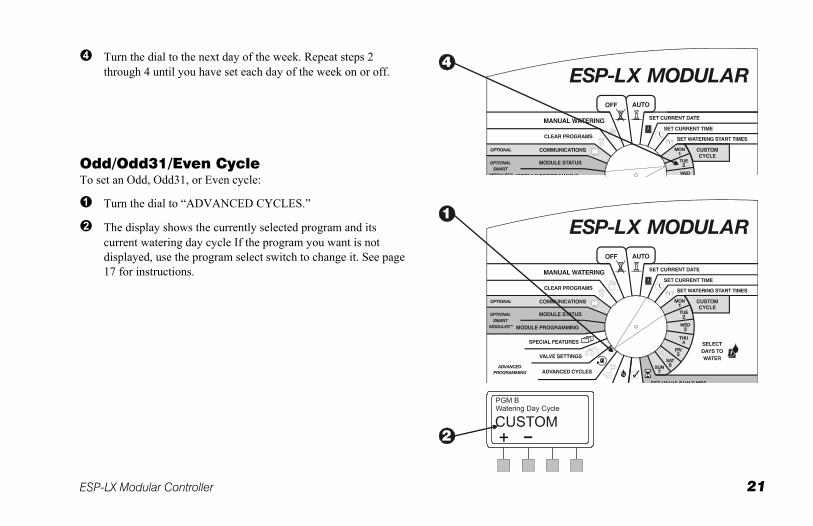
Turn the dial to the next day of the week. Repeat steps 2 through 4 until you have set each day of the week on or off.
Odd/Odd31/Even Cycle To set an Odd, Odd31, or Even cycle:
Turn the dial to “ADVANCED CYCLES.”
The display shows the currently selected program and its current watering day cycle If the program you want is not displayed, use the program select switch to change it. See page 17 for instructions.
22 ESP-LX Modular Controller
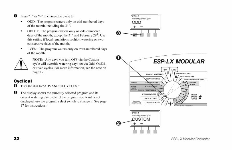
Press “+” or “–” to change the cycle to: ODD: The program waters only on odd-numbered days
of the month, including the 31st. ODD31: The program waters only on odd-numbered
days of the month, except the 31st and February 29th. Use this setting if local regulations prohibit watering on two consecutive days of the month.
EVEN: The program waters only on even-numbered days of the month.
NOTE: Any days you turn OFF via the Custom cycle will override watering days set via Odd, Odd31, or Even cycles. For more information, see the note on page 19.
Cyclical Turn the dial to “ADVANCED CYCLES.”
The display shows the currently selected program and its current watering day cycle. If the program you want is not displayed, use the program select switch to change it. See page 17 for instructions.
ESP-LX Modular Controller 23
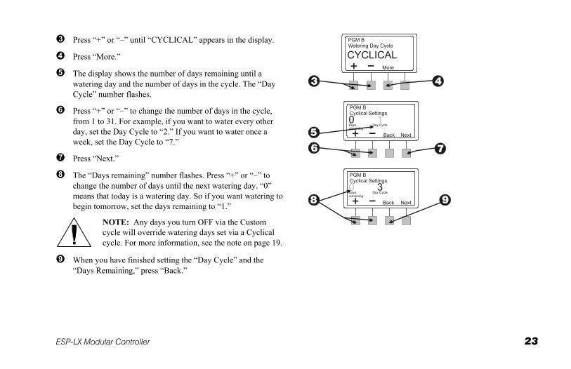
Press “+” or “–” until “CYCLICAL” appears in the display.
Press “More.”
The display shows the number of days remaining until a watering day and the number of days in the cycle. The “Day Cycle” number flashes.
Press “+” or “–” to change the number of days in the cycle, from 1 to 31. For example, if you want to water every other day, set the Day Cycle to “2.” If you want to water once a week, set the Day Cycle to “7.”
Press “Next.”
The “Days remaining” number flashes. Press “+” or “–” to change the number of days until the next watering day. “0” means that today is a watering day. So if you want watering to begin tomorrow, set the days remaining to “1.”
NOTE: Any days you turn OFF via the Custom cycle will override watering days set via a Cyclical cycle. For more information, see the note on page 19.
When you have finished setting the “Day Cycle” and the “Days Remaining,” press “Back.”
24 ESP-LX Modular Controller
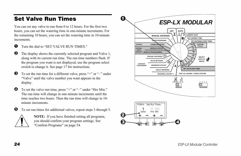
Set Valve Run Times You can set any valve to run from 0 to 12 hours. For the first two hours, you can set the watering time in one-minute increments. For the remaining 10 hours, you can set the watering time in 10-minute increments.
Turn the dial to “SET VALVE RUN TIMES.”
The display shows the currently selected program and Valve 1, along with its current run time. The run time numbers flash. If the program you want is not displayed, use the program select switch to change it. See page 17 for instructions.
To set the run time for a different valve, press “+” or “–” under “Valve” until the valve number you want appears in the display.
To set the valve run time, press “+” or “–” under “Hrs Min.” The run time will change in one-minute increments until the time reaches two hours. Then the run time will change in 10-minute increments.
To set run times for additional valves, repeat steps 3 through 5.
NOTE: If you have finished setting all programs, you should confirm your program settings. See “Confirm Programs” on page 54.
ESP-LX Modular Controller 25
ADVANCED PROGRAMMING
Seasonal Adjust % The seasonal adjustment feature lets you scale the run times of all valves up or down by a selected percentage. You can set the percentage from 0% to 300%, in increments of one percent. The normal programmed run time is 100%.
You can set the percentage to affect:
All valves on an individual program (see page 26)
All valves by month (see page 27)
You can use the seasonal adjustment feature to cut back watering during cool winter months, or to increase watering during periods of unusual heat. In addition, you can use the 0% setting to shut off a program temporarily.
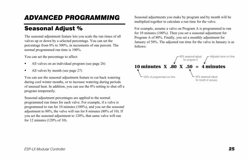
Seasonal adjustment percentages are applied to the normal programmed run times for each valve. For example, if a valve is programmed to run for 10 minutes (100%), and you set the seasonal adjustment to 80%, the valve will run for 8 minutes (80% of 10). If you set the seasonal adjustment to 120%, that same valve will run for 12 minutes (120% of 10).
Seasonal adjustments you make by program and by month will be multiplied together to calculate a run time for the valve.
For example, assume a valve on Program A is programmed to run for 10 minutes (100%). Then you set a seasonal adjustment for Program A of 80%. Finally, you set a monthly adjustment for January of 50%. The adjusted run time for the valve in January is as follows:
26 ESP-LX Modular Controller
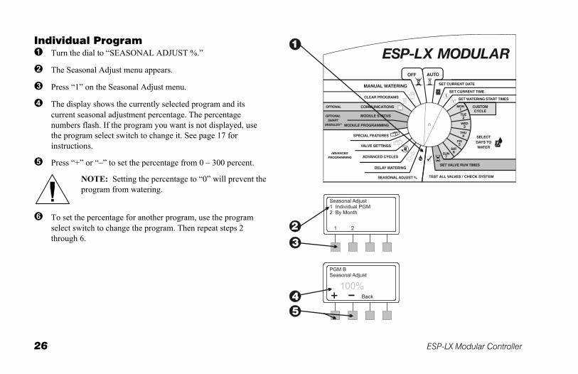
Individual Program Turn the dial to “SEASONAL ADJUST %.”
The Seasonal Adjust menu appears.
Press “1” on the Seasonal Adjust menu.
The display shows the currently selected program and its current seasonal adjustment percentage. The percentage numbers flash. If the program you want is not displayed, use the program select switch to change it. See page 17 for instructions.
Press “+” or “–” to set the percentage from 0 – 300 percent.
NOTE: Setting the percentage to “0” will prevent the program from watering.
To set the percentage for another program, use the program select switch to change the program. Then repeat steps 2 through 6.
ESP-LX Modular Controller 27
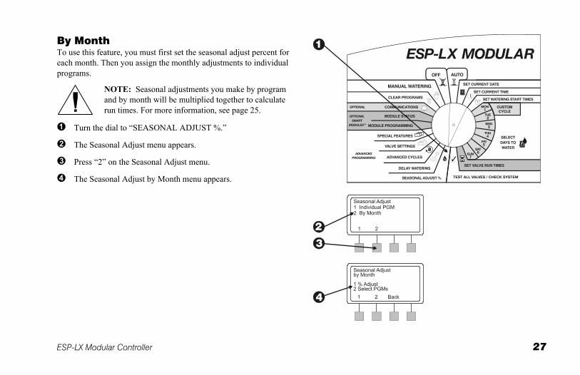
By Month To use this feature, you must first set the seasonal adjust percent for each month. Then you assign the monthly adjustments to individual programs.
NOTE: Seasonal adjustments you make by program and by month will be multiplied together to calculate run times. For more information, see page 25.
Turn the dial to “SEASONAL ADJUST %.”
The Seasonal Adjust menu appears.
Press “2” on the Seasonal Adjust menu.
The Seasonal Adjust by Month menu appears.
28 ESP-LX Modular Controller
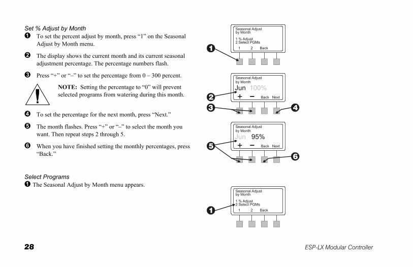
Set % Adjust by Month To set the percent adjust by month, press “1” on the Seasonal
Adjust by Month menu.
The display shows the current month and its current seasonal adjustment percentage. The percentage numbers flash.
Press “+” or “–” to set the percentage from 0 – 300 percent.
NOTE: Setting the percentage to “0” will prevent selected programs from watering during this month.
To set the percentage for the next month, press “Next.”
The month flashes. Press “+” or “–” to select the month you want. Then repeat steps 2 through 5.
When you have finished setting the monthly percentages, press “Back.”
Select Programs The Seasonal Adjust by Month menu appears.
ESP-LX Modular Controller 29
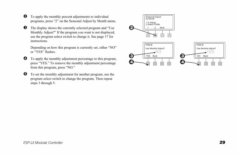
To apply the monthly percent adjustments to individual programs, press “2” on the Seasonal Adjust by Month menu.
The display shows the currently selected program and “Use Monthly Adjust?” If the program you want is not displayed, use the program select switch to change it. See page 17 for instructions.
Depending on how this program is currently set, either “NO” or “YES” flashes.
To apply the monthly adjustment percentage to this program, press “YES.” To remove the monthly adjustment percentage from this program, press “NO.”
To set the monthly adjustment for another program, use the program select switch to change the program. Then repeat steps 3 through 5.
30 ESP-LX Modular Controller
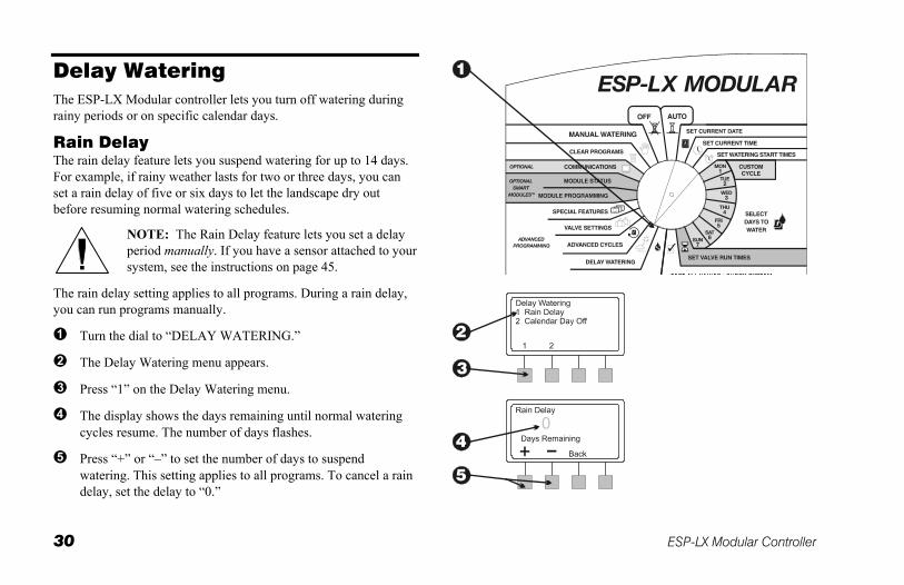
Delay Watering The ESP-LX Modular controller lets you turn off watering during rainy periods or on specific calendar days.
Rain Delay The rain delay feature lets you suspend watering for up to 14 days. For example, if rainy weather lasts for two or three days, you can set a rain delay of five or six days to let the landscape dry out before resuming normal watering schedules.
NOTE: The Rain Delay feature lets you set a delay period manually. If you have a sensor attached to your system, see the instructions on page 45.
The rain delay setting applies to all programs. During a rain delay, you can run programs manually.
Turn the dial to “DELAY WATERING.”
The Delay Watering menu appears.
Press “1” on the Delay Watering menu.
The display shows the days remaining until normal watering cycles resume. The number of days flashes.
Press “+” or “–” to set the number of days to suspend watering. This setting applies to all programs. To cancel a rain delay, set the delay to “0.”
ESP-LX Modular Controller 31
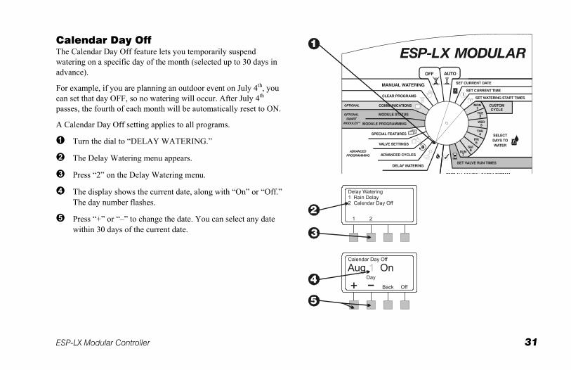
Calendar Day Off The Calendar Day Off feature lets you temporarily suspend watering on a specific day of the month (selected up to 30 days in advance).
For example, if you are planning an outdoor event on July 4th, you can set that day OFF, so no watering will occur. After July 4th passes, the fourth of each month will be automatically reset to ON.
A Calendar Day Off setting applies to all programs.
Turn the dial to “DELAY WATERING.”
The Delay Watering menu appears.
Press “2” on the Delay Watering menu.
The display shows the current date, along with “On” or “Off.” The day number flashes.
Press “+” or “–” to change the date. You can select any date within 30 days of the current date.
32 ESP-LX Modular Controller
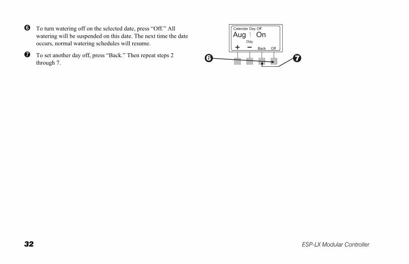
To turn watering off on the selected date, press “Off.” All watering will be suspended on this date. The next time the date occurs, normal watering schedules will resume.
To set another day off, press “Back.” Then repeat steps 2 through 7.
ESP-LX Modular Controller 33
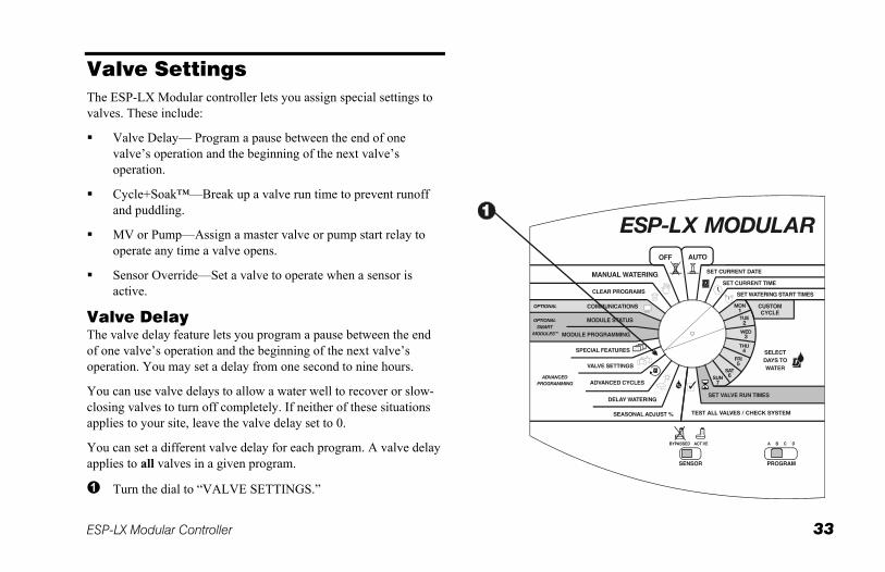
Valve Settings The ESP-LX Modular controller lets you assign special settings to valves. These include:
Valve Delay— Program a pause between the end of one valve’s operation and the beginning of the next valve’s operation.
Cycle+Soak™—Break up a valve run time to prevent runoff and puddling.
MV or Pump—Assign a master valve or pump start relay to operate any time a valve opens.
Sensor Override—Set a valve to operate when a sensor is active.
Valve Delay The valve delay feature lets you program a pause between the end of one valve’s operation and the beginning of the next valve’s operation. You may set a delay from one second to nine hours.
You can use valve delays to allow a water well to recover or slow-closing valves to turn off completely. If neither of these situations applies to your site, leave the valve delay set to 0.
You can set a different valve delay for each program. A valve delay applies to all valves in a given program.
Turn the dial to “VALVE SETTINGS.”
34 ESP-LX Modular Controller
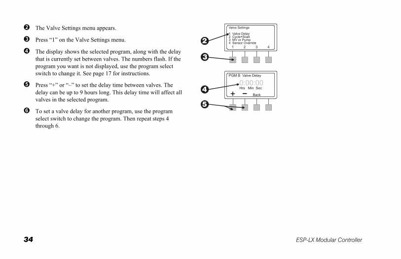
The Valve Settings menu appears.
Press “1” on the Valve Settings menu.
The display shows the selected program, along with the delay that is currently set between valves. The numbers flash. If the program you want is not displayed, use the program select switch to change it. See page 17 for instructions.
Press “+” or “–” to set the delay time between valves. The delay can be up to 9 hours long. This delay time will affect all valves in the selected program.
To set a valve delay for another program, use the program select switch to change the program. Then repeat steps 4 through 6.
ESP-LX Modular Controller 35
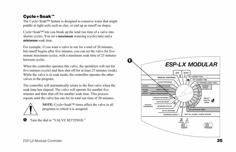
Cycle+Soak™ The Cycle+Soak™ feature is designed to conserve water that might puddle in tight soils such as clay, or end up as runoff on slopes.
Cycle+Soak™ lets you break up the total run time of a valve into shorter cycles. You set a maximum watering (cycle) time and a minimum soak time.
For example, if you want a valve to run for a total of 20 minutes, but runoff begins after five minutes, you can set the valve for five-minute maximum cycles, with a minimum soak time of 25 minutes between cycles.
When the controller operates this valve, the sprinklers will run for five minutes (cycle) and then shut off for at least 25 minutes (soak). While the valve is in soak mode, the controller operates the other valves in the program.
The controller will automatically return to the first valve when the soak time has elapsed. The valve will operate for another five minutes and then shut off for another soak time. This process repeats until the valve has run for its total run time of 20 minutes.
NOTE: Cycle+Soak™ times affect the valve in all programs to which it is assigned.
Turn the dial to “VALVE SETTINGS.”
36 ESP-LX Modular Controller
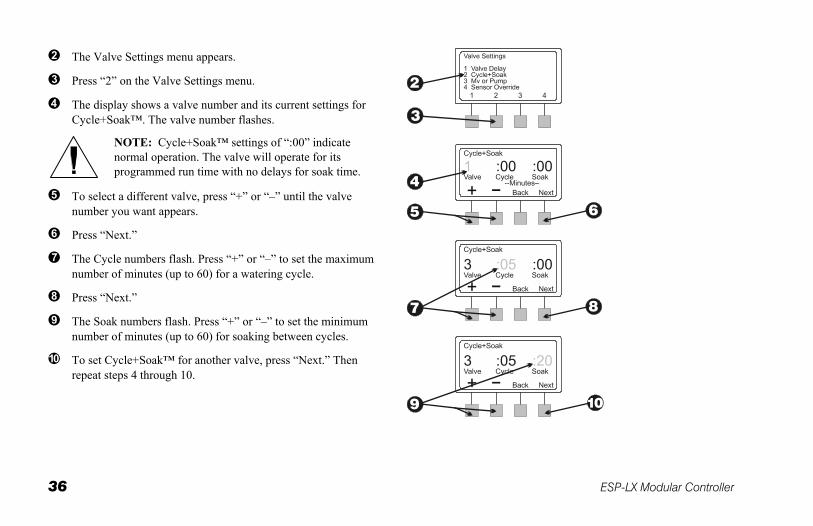
The Valve Settings menu appears.
Press “2” on the Valve Settings menu.
The display shows a valve number and its current settings for Cycle+Soak™. The valve number flashes.
NOTE: Cycle+Soak™ settings of “:00” indicate normal operation. The valve will operate for its programmed run time with no delays for soak time.
To select a different valve, press “+” or “–” until the valve number you want appears.
Press “Next.”
The Cycle numbers flash. Press “+” or “–” to set the maximum number of minutes (up to 60) for a watering cycle.
Press “Next.”
The Soak numbers flash. Press “+” or “–” to set the minimum number of minutes (up to 60) for soaking between cycles.
To set Cycle+Soak™ for another valve, press “Next.” Then repeat steps 4 through 10.
ESP-LX Modular Controller 37
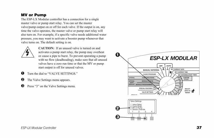
MV or Pump The ESP-LX Modular controller has a connection for a single master valve or pump start relay. You can set the master valve/pump output on or off for each valve. If the output is on, any time the valve operates, the master valve or pump start relay will also turn on. For example, if a specific valve needs additional water pressure, you may want to activate a booster pump whenever that valve turns on. The default setting is on.
CAUTION: If an unused valve is turned on and activates a pump start relay, the pump may overheat or cause a pipe to burst. To prevent operating a pump with no flow (deadheading), make sure that all unused valves have a zero run time or that the MV or pump start output is off for unused valves.
Turn the dial to “VALVE SETTINGS.”
The Valve Settings menu appears.
Press “3” on the Valve Settings menu.
38 ESP-LX Modular Controller
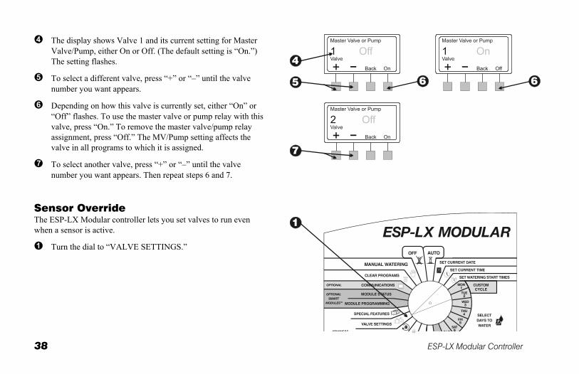
The display shows Valve 1 and its current setting for Master Valve/Pump, either On or Off. (The default setting is “On.”) The setting flashes.
To select a different valve, press “+” or “–” until the valve number you want appears.
Depending on how this valve is currently set, either “On” or “Off” flashes. To use the master valve or pump relay with this valve, press “On.” To remove the master valve/pump relay assignment, press “Off.” The MV/Pump setting affects the valve in all programs to which it is assigned.
To select another valve, press “+” or “–” until the valve number you want appears. Then repeat steps 6 and 7.
Sensor Override The ESP-LX Modular controller lets you set valves to run even when a sensor is active.
Turn the dial to “VALVE SETTINGS.”
ESP-LX Modular Controller 39
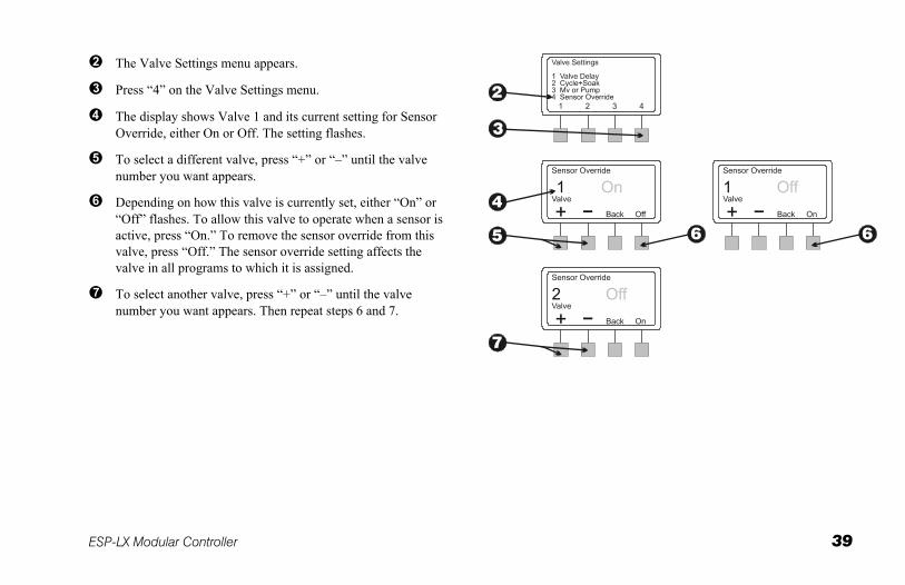
The Valve Settings menu appears.
Press “4” on the Valve Settings menu.
The display shows Valve 1 and its current setting for Sensor Override, either On or Off. The setting flashes.
To select a different valve, press “+” or “–” until the valve number you want appears.
Depending on how this valve is currently set, either “On” or “Off” flashes. To allow this valve to operate when a sensor is active, press “On.” To remove the sensor override from this valve, press “Off.” The sensor override setting affects the valve in all programs to which it is assigned.
To select another valve, press “+” or “–” until the valve number you want appears. Then repeat steps 6 and 7.
40 ESP-LX Modular Controller
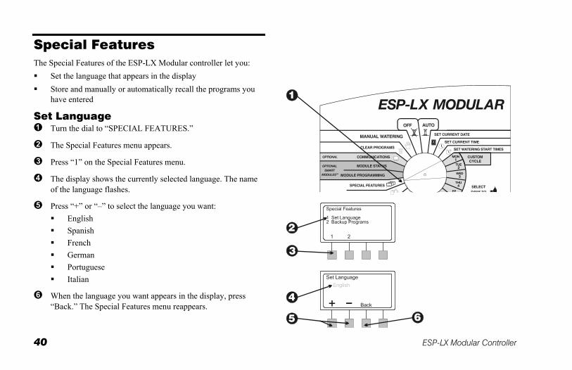
Special Features The Special Features of the ESP-LX Modular controller let you: Set the language that appears in the display Store and manually or automatically recall the programs you
have entered
Set Language Turn the dial to “SPECIAL FEATURES.”
The Special Features menu appears.
Press “1” on the Special Features menu.
The display shows the currently selected language. The name of the language flashes.
Press “+” or “–” to select the language you want: English Spanish French German Portuguese Italian
When the language you want appears in the display, press “Back.” The Special Features menu reappears.
ESP-LX Modular Controller 41
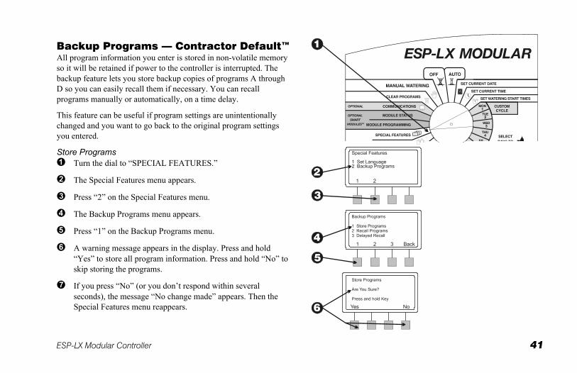
Backup Programs — Contractor Default™ All program information you enter is stored in non-volatile memory so it will be retained if power to the controller is interrupted. The backup feature lets you store backup copies of programs A through D so you can easily recall them if necessary. You can recall programs manually or automatically, on a time delay.
This feature can be useful if program settings are unintentionally changed and you want to go back to the original program settings you entered.
Store Programs Turn the dial to “SPECIAL FEATURES.”
The Special Features menu appears.
Press “2” on the Special Features menu.
The Backup Programs menu appears.
Press “1” on the Backup Programs menu.
A warning message appears in the display. Press and hold “Yes” to store all program information. Press and hold “No” to skip storing the programs.
If you press “No” (or you don’t respond within several seconds), the message “No change made” appears. Then the Special Features menu reappears.
42 ESP-LX Modular Controller
If you press “Yes,” the message “Please wait. Storing …” appears, followed by “Stored.” Then the Special Features menu reappears.
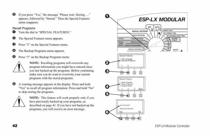
Recall Programs Turn the dial to “SPECIAL FEATURES.”
The Special Features menu appears.
Press “2” on the Special Features menu.
The Backup Programs menu appears.
Press “2” on the Backup Programs menu.
NOTE: Recalling programs will overwrite any program information you might have entered since you last backed up the programs. Before continuing, make sure you do want to overwrite your current programs with the stored programs.
A warning message appears in the display. Press and hold “Yes” to recall all program information. Press and hold “No” to skip storing the programs.
NOTE: This feature will work properly only if you have previously backed up your programs, as described on page 41. If you have not backed up the programs, you will receive an error message.
ESP-LX Modular Controller 43
If you press “No” (or you don’t respond within several seconds), the message “No change made” appears. Then the Special Features menu reappears.
If you press “Yes,” the message “Programs Recalled” appears. Then the Special Features menu reappears.
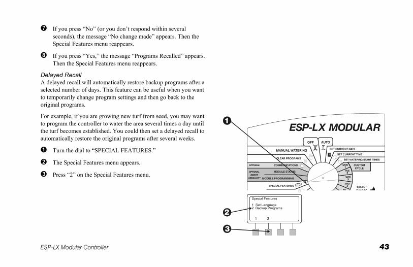
Delayed Recall A delayed recall will automatically restore backup programs after a selected number of days. This feature can be useful when you want to temporarily change program settings and then go back to the original programs.
For example, if you are growing new turf from seed, you may want to program the controller to water the area several times a day until the turf becomes established. You could then set a delayed recall to automatically restore the original programs after several weeks.
Turn the dial to “SPECIAL FEATURES.”
The Special Features menu appears.
Press “2” on the Special Features menu.
44 ESP-LX Modular Controller
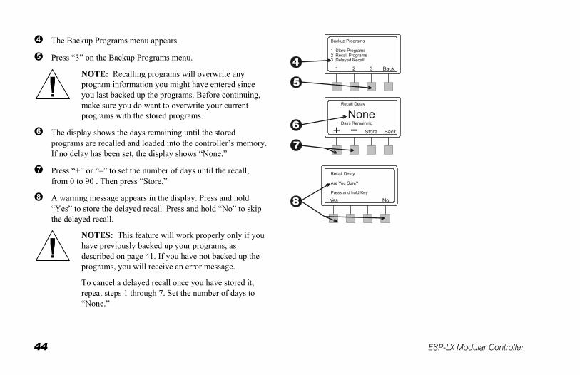
The Backup Programs menu appears.
Press “3” on the Backup Programs menu.
NOTE: Recalling programs will overwrite any program information you might have entered since you last backed up the programs. Before continuing, make sure you do want to overwrite your current programs with the stored programs.
The display shows the days remaining until the stored programs are recalled and loaded into the controller’s memory. If no delay has been set, the display shows “None.”
Press “+” or “–” to set the number of days until the recall, from 0 to 90 . Then press “Store.”
A warning message appears in the display. Press and hold “Yes” to store the delayed recall. Press and hold “No” to skip the delayed recall.
NOTES: This feature will work properly only if you have previously backed up your programs, as described on page 41. If you have not backed up the programs, you will receive an error message.
To cancel a delayed recall once you have stored it, repeat steps 1 through 7. Set the number of days to “None.”
ESP-LX Modular Controller 45
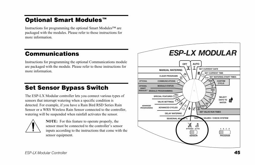
Optional Smart Modules™ Instructions for programming the optional Smart Modules™ are packaged with the modules. Please refer to those instructions for more information.
Communications Instructions for programming the optional Communications module are packaged with the module. Please refer to those instructions for more information.
Set Sensor Bypass Switch The ESP-LX Modular controller lets you connect various types of sensors that interrupt watering when a specific condition is detected. For example, if you have a Rain Bird RSD Series Rain Sensor or a WRS Wireless Rain Sensor connected to the controller, watering will be suspended when rainfall activates the sensor.
NOTE: For this feature to operate properly, the sensor must be connected to the controller’s sensor inputs according to the instructions that come with the sensor equipment.
46 ESP-LX Modular Controller
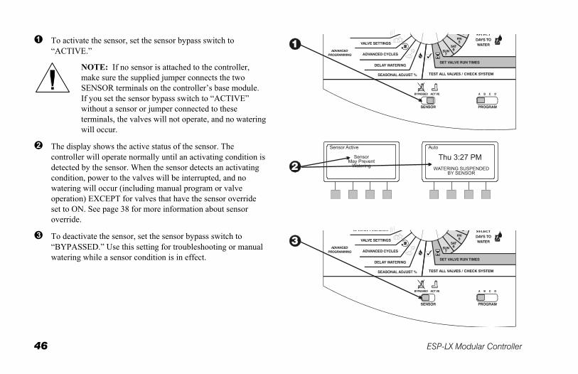
To activate the sensor, set the sensor bypass switch to “ACTIVE.”
NOTE: If no sensor is attached to the controller, make sure the supplied jumper connects the two SENSOR terminals on the controller’s base module. If you set the sensor bypass switch to “ACTIVE” without a sensor or jumper connected to these terminals, the valves will not operate, and no watering will occur.
The display shows the active status of the sensor. The controller will operate normally until an activating condition is detected by the sensor. When the sensor detects an activating condition, power to the valves will be interrupted, and no watering will occur (including manual program or valve operation) EXCEPT for valves that have the sensor override set to ON. See page 38 for more information about sensor override.
To deactivate the sensor, set the sensor bypass switch to “BYPASSED.” Use this setting for troubleshooting or manual watering while a sensor condition is in effect.
ESP-LX Modular Controller 47
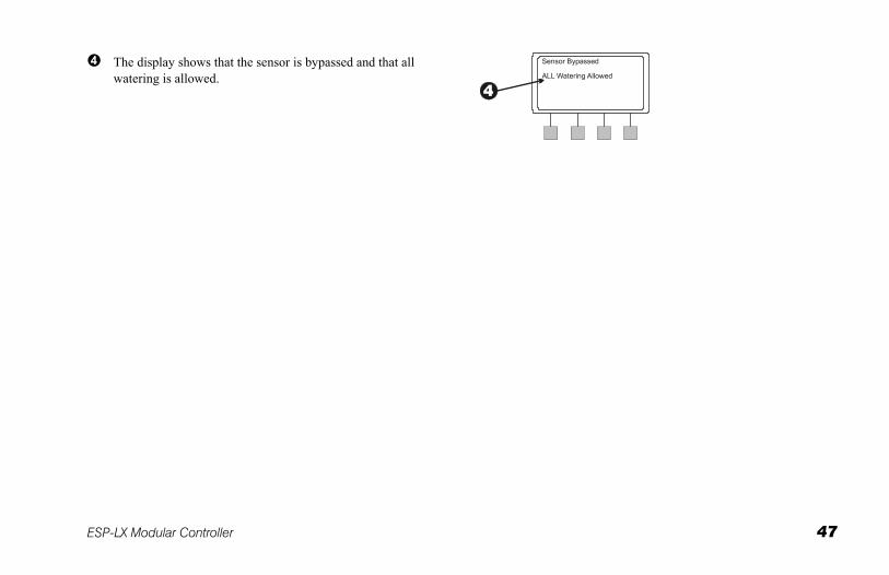
The display shows that the sensor is bypassed and that all watering is allowed.
48 ESP-LX Modular Controller
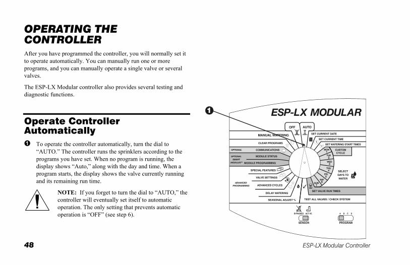
OPERATING THE CONTROLLER After you have programmed the controller, you will normally set it to operate automatically. You can manually run one or more programs, and you can manually operate a single valve or several valves.
The ESP-LX Modular controller also provides several testing and diagnostic functions.
Operate Controller Automatically
To operate the controller automatically, turn the dial to “AUTO.” The controller runs the sprinklers according to the programs you have set. When no program is running, the display shows “Auto,” along with the day and time. When a program starts, the display shows the valve currently running and its remaining run time.
NOTE: If you forget to turn the dial to “AUTO,” the controller will eventually set itself to automatic operation. The only setting that prevents automatic operation is “OFF” (see step 6).
ESP-LX Modular Controller 49
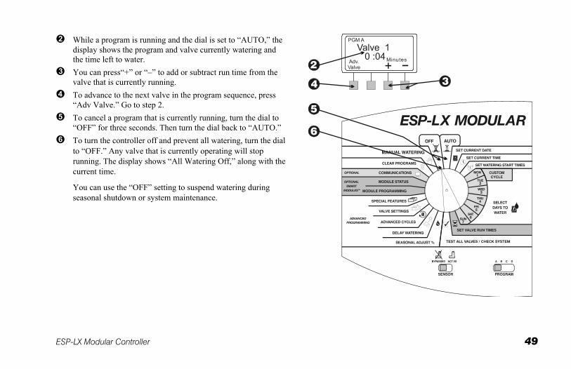
While a program is running and the dial is set to “AUTO,” the display shows the program and valve currently watering and the time left to water.
You can press“+” or “–” to add or subtract run time from the valve that is currently running.
To advance to the next valve in the program sequence, press “Adv Valve.” Go to step 2.
To cancel a program that is currently running, turn the dial to “OFF” for three seconds. Then turn the dial back to “AUTO.”
To turn the controller off and prevent all watering, turn the dial to “OFF.” Any valve that is currently operating will stop running. The display shows “All Watering Off,” along with the current time.
You can use the “OFF” setting to suspend watering during seasonal shutdown or system maintenance.
50 ESP-LX Modular Controller
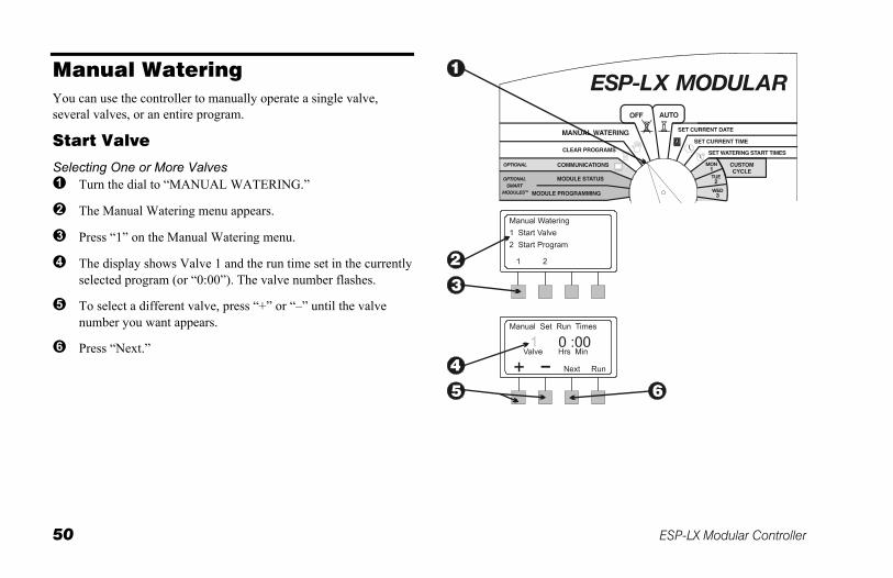
Manual Watering You can use the controller to manually operate a single valve, several valves, or an entire program.
Start Valve
Selecting One or More Valves Turn the dial to “MANUAL WATERING.”
The Manual Watering menu appears.
Press “1” on the Manual Watering menu.
The display shows Valve 1 and the run time set in the currently selected program (or “0:00”). The valve number flashes.
To select a different valve, press “+” or “–” until the valve number you want appears.
Press “Next.”
ESP-LX Modular Controller 51
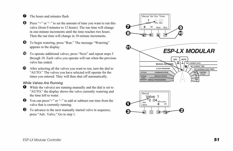
The hours and minutes flash.
Press “+” or “–” to set the amount of time you want to run this valve (from 0 minutes to 12 hours). The run time will change in one-minute increments until the time reaches two hours. Then the run time will change in 10-minute increments.
To begin watering, press “Run.” The message “Watering” appears in the display.
To operate additional valves, press “Next” and repeat steps 5 through 10. Each valve you operate will run when the previous valve has ended.
After selecting all the valves you want to run, turn the dial to “AUTO.” The valves you have selected will operate for the times you entered. They will then shut off automatically.
While Valves Are Running While the valve(s) are running manually and the dial is set to
“AUTO,” the display shows the valve currently watering and the time left to water.
You can press“+” or “–” to add or subtract run time from the valve that is currently running.
To advance to the next manually started valve in sequence, press “Adv. Valve.” Go to step 1.
52 ESP-LX Modular Controller
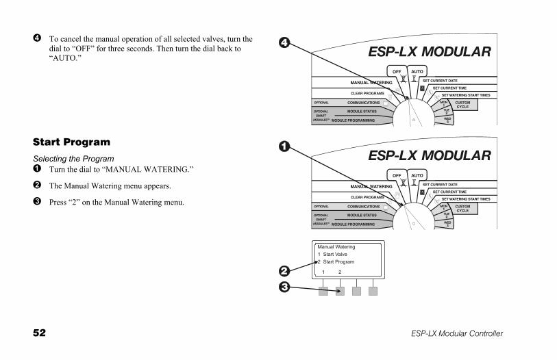
To cancel the manual operation of all selected valves, turn the dial to “OFF” for three seconds. Then turn the dial back to “AUTO.”
Start Program
Selecting the Program Turn the dial to “MANUAL WATERING.”
The Manual Watering menu appears.
Press “2” on the Manual Watering menu.
ESP-LX Modular Controller 53
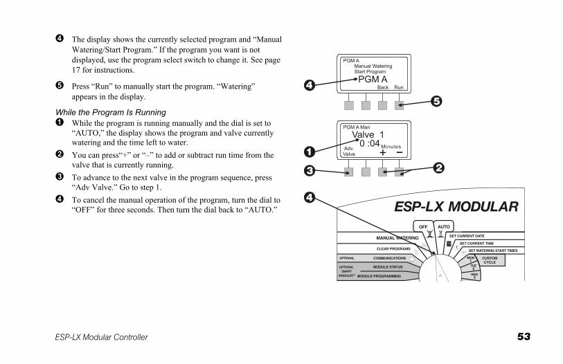
The display shows the currently selected program and “Manual Watering/Start Program.” If the program you want is not displayed, use the program select switch to change it. See page 17 for instructions.
Press “Run” to manually start the program. “Watering” appears in the display.
While the Program Is Running While the program is running manually and the dial is set to
“AUTO,” the display shows the program and valve currently watering and the time left to water.
You can press“+” or “–” to add or subtract run time from the valve that is currently running.
To advance to the next valve in the program sequence, press “Adv Valve.” Go to step 1.
To cancel the manual operation of the program, turn the dial to “OFF” for three seconds. Then turn the dial back to “AUTO.”
54 ESP-LX Modular Controller
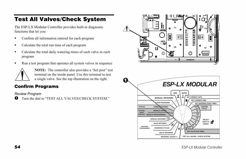
Test All Valves/Check System The ESP-LX Modular Controller provides built-in diagnostic functions that let you:
Confirm all information entered for each program
Calculate the total run time of each program
Calculate the total daily watering times of each valve in each program
Run a test program that operates all system valves in sequence
NOTE: The controller also provides a “hot post” test terminal on the inside panel. Use this terminal to test a single valve. See the top illustration on the right.
Confirm Programs
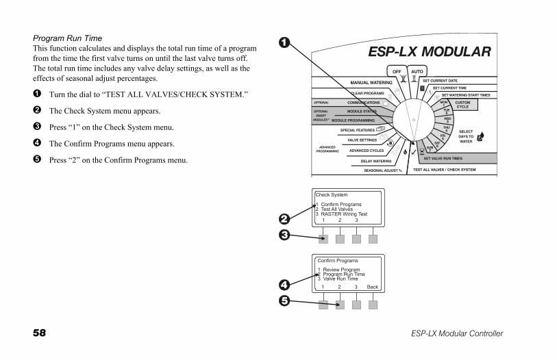
Review Program Turn the dial to “TEST ALL VALVES/CHECK SYSTEM.”
ESP-LX Modular Controller 55
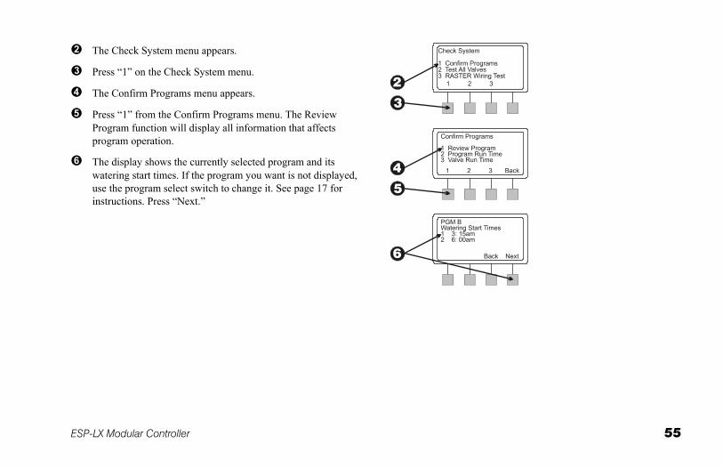
The Check System menu appears.
Press “1” on the Check System menu.
The Confirm Programs menu appears.
Press “1” from the Confirm Programs menu. The Review Program function will display all information that affects program operation.
The display shows the currently selected program and its watering start times. If the program you want is not displayed, use the program select switch to change it. See page 17 for instructions. Press “Next.”
56 ESP-LX Modular Controller
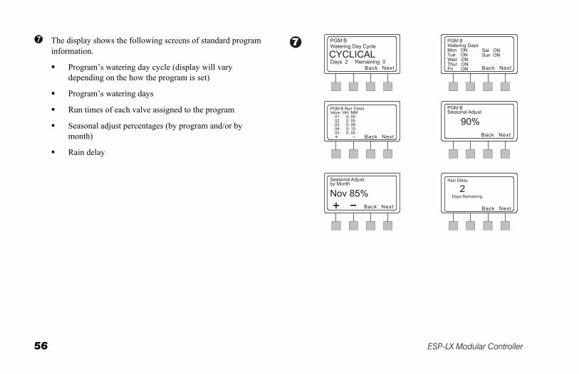
The display shows the following screens of standard program information.
Program’s watering day cycle (display will vary depending on the how the program is set)
Program’s watering days
Run times of each valve assigned to the program
Seasonal adjust percentages (by program and/or by month)
Rain delay
ESP-LX Modular Controller 57
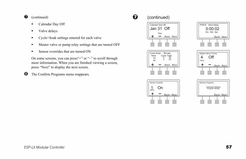
(continued)
Calendar Day Off
Valve delays
Cycle+Soak settings entered for each valve
Master valve or pump relay settings that are turned OFF
Sensor overrides that are turned ON
On some screens, you can press“+” or “–” to scroll through more information. When you are finished viewing a screen, press “Next” to display the next screen.
The Confirm Programs menu reappears.
58 ESP-LX Modular Controller
Program Run Time This function calculates and displays the total run time of a program from the time the first valve turns on until the last valve turns off. The total run time includes any valve delay settings, as well as the effects of seasonal adjust percentages.
Turn the dial to “TEST ALL VALVES/CHECK SYSTEM.”
The Check System menu appears.
Press “1” on the Check System menu.
The Confirm Programs menu appears.
Press “2” on the Confirm Programs menu.
ESP-LX Modular Controller 59
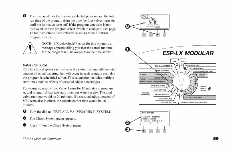
The display shows the currently selected program and the total run time of the program from the time the first valves turns on until the last valve turns off. If the program you want is not displayed, use the program select switch to change it. See page 17 for instructions. Press “Back” to return to the Confirm Programs menu.
NOTE: If Cycle+Soak™ is set for this program, a message appears telling you that the actual run time for the program will be longer than the time shown.
Valve Run Time This function displays each valve in the system, along with the total amount of actual watering that will occur in each program each day the program is scheduled to run. This calculation includes multiple start times and the effects of seasonal adjust percentages.
For example, assume that Valve 1 runs for 10 minutes in program A, and program A has two start times per watering day. The total valve run time would be 20 minutes. If a seasonal adjust percent of 80% were also in effect, the calculated run time would be 16 minutes.
Turn the dial to “TEST ALL VALVES/CHECK SYSTEM.”
The Check System menu appears.
Press “1” on the Check System menu.
60 ESP-LX Modular Controller
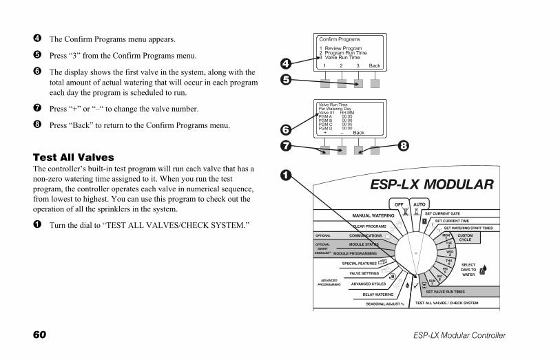
The Confirm Programs menu appears.
Press “3” from the Confirm Programs menu.
The display shows the first valve in the system, along with the total amount of actual watering that will occur in each program each day the program is scheduled to run.
Press “+” or “–“ to change the valve number.
Press “Back” to return to the Confirm Programs menu.
Test All Valves The controller’s built-in test program will run each valve that has a non-zero watering time assigned to it. When you run the test program, the controller operates each valve in numerical sequence, from lowest to highest. You can use this program to check out the operation of all the sprinklers in the system.
Turn the dial to “TEST ALL VALVES/CHECK SYSTEM.”
ESP-LX Modular Controller 61
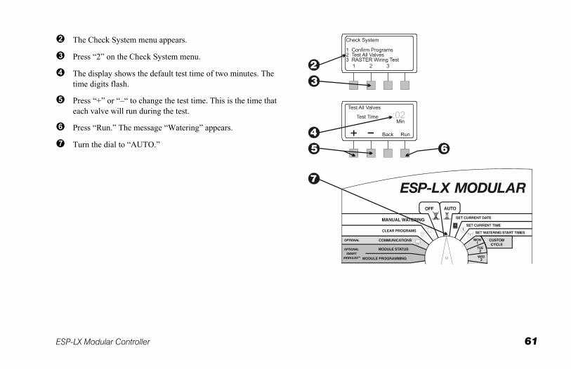
The Check System menu appears.
Press “2” on the Check System menu.
The display shows the default test time of two minutes. The time digits flash.
Press “+” or “–“ to change the test time. This is the time that each valve will run during the test.
Press “Run.” The message “Watering” appears.
Turn the dial to “AUTO.”
62 ESP-LX Modular Controller
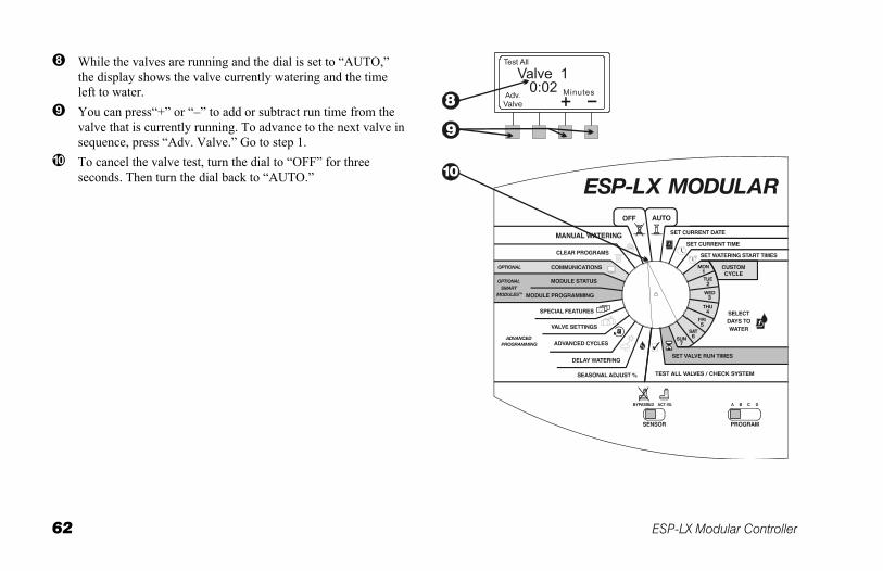
While the valves are running and the dial is set to “AUTO,” the display shows the valve currently watering and the time left to water.
You can press“+” or “–” to add or subtract run time from the valve that is currently running. To advance to the next valve in sequence, press “Adv. Valve.” Go to step 1.
To cancel the valve test, turn the dial to “OFF” for three seconds. Then turn the dial back to “AUTO.”
ESP-LX Modular Controller 63
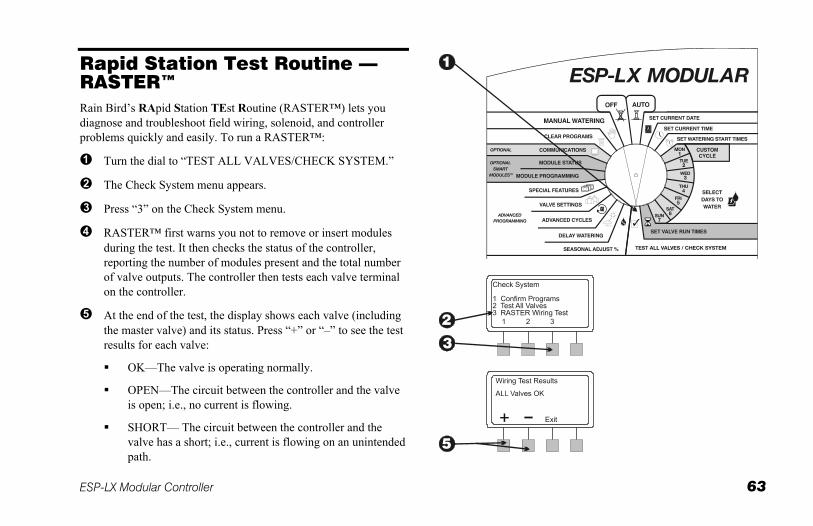
Rapid Station Test Routine — RASTER™ Rain Bird’s RApid Station TEst Routine (RASTER™) lets you diagnose and troubleshoot field wiring, solenoid, and controller problems quickly and easily. To run a RASTER™:
Turn the dial to “TEST ALL VALVES/CHECK SYSTEM.”
The Check System menu appears.
Press “3” on the Check System menu.
RASTER™ first warns you not to remove or insert modules during the test. It then checks the status of the controller, reporting the number of modules present and the total number of valve outputs. The controller then tests each valve terminal on the controller.
At the end of the test, the display shows each valve (including the master valve) and its status. Press “+” or “–” to see the test results for each valve:
OK—The valve is operating normally.
OPEN—The circuit between the controller and the valve is open; i.e., no current is flowing.
SHORT— The circuit between the controller and the valve has a short; i.e., current is flowing on an unintended path.
64 ESP-LX Modular Controller
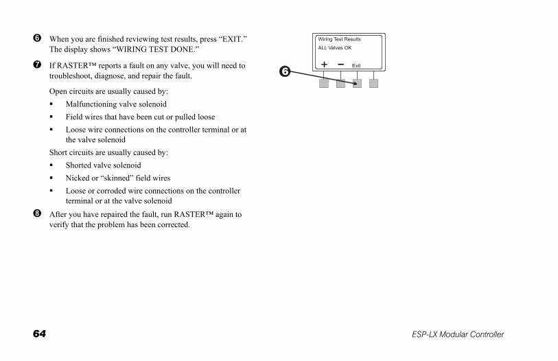
When you are finished reviewing test results, press “EXIT.” The display shows “WIRING TEST DONE.”
If RASTER™ reports a fault on any valve, you will need to troubleshoot, diagnose, and repair the fault.
Open circuits are usually caused by: Malfunctioning valve solenoid Field wires that have been cut or pulled loose Loose wire connections on the controller terminal or at
the valve solenoid Short circuits are usually caused by:
Shorted valve solenoid Nicked or “skinned” field wires Loose or corroded wire connections on the controller
terminal or at the valve solenoid
After you have repaired the fault, run RASTER™ again to verify that the problem has been corrected.
ESP-LX Modular Controller 65
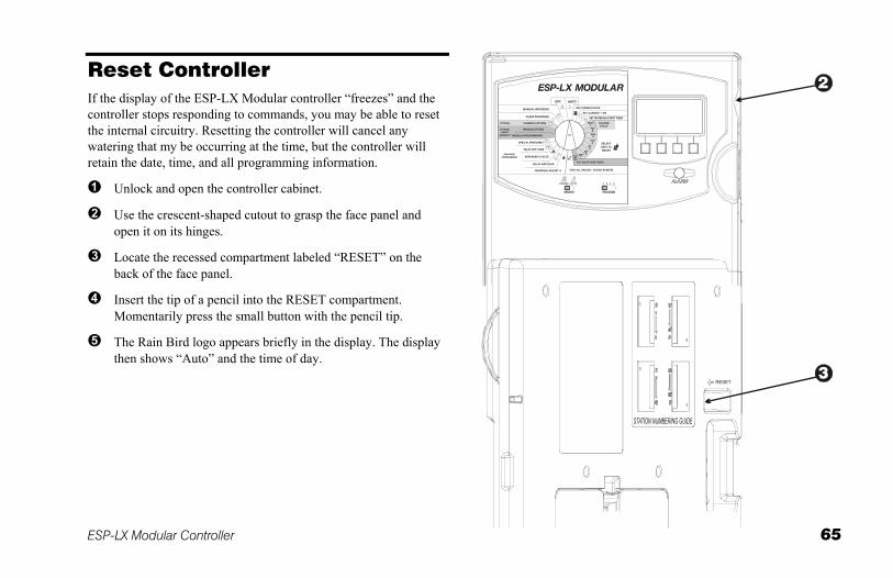
Reset Controller If the display of the ESP-LX Modular controller “freezes” and the controller stops responding to commands, you may be able to reset the internal circuitry. Resetting the controller will cancel any watering that my be occurring at the time, but the controller will retain the date, time, and all programming information.
Unlock and open the controller cabinet.
Use the crescent-shaped cutout to grasp the face panel and open it on its hinges.
Locate the recessed compartment labeled “RESET” on the back of the face panel.
Insert the tip of a pencil into the RESET compartment. Momentarily press the small button with the pencil tip.
The Rain Bird logo appears briefly in the display. The display then shows “Auto” and the time of day.
66 ESP-LX Modular Controller
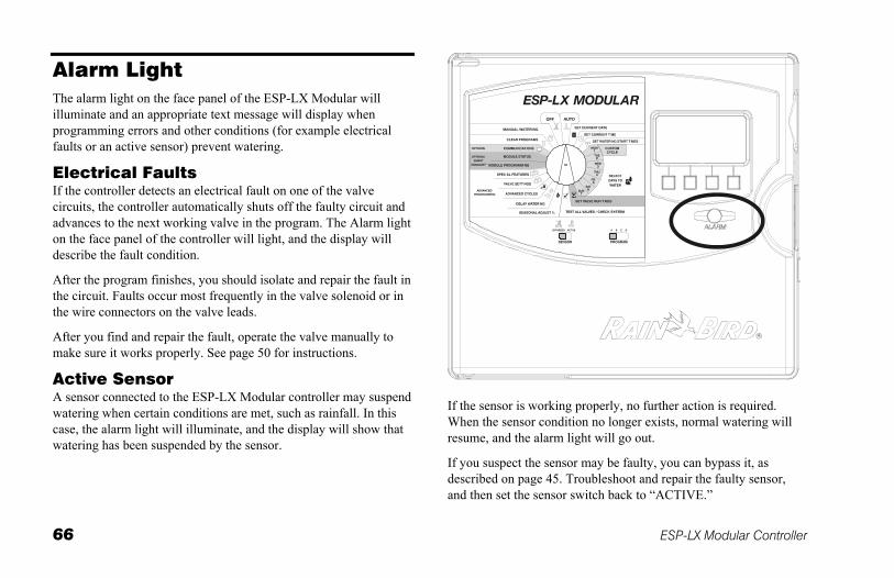
Alarm Light The alarm light on the face panel of the ESP-LX Modular will illuminate and an appropriate text message will display when programming errors and other conditions (for example electrical faults or an active sensor) prevent watering.
Electrical Faults If the controller detects an electrical fault on one of the valve circuits, the controller automatically shuts off the faulty circuit and advances to the next working valve in the program. The Alarm light on the face panel of the controller will light, and the display will describe the fault condition.
After the program finishes, you should isolate and repair the fault in the circuit. Faults occur most frequently in the valve solenoid or in the wire connectors on the valve leads.
After you find and repair the fault, operate the valve manually to make sure it works properly. See page 50 for instructions.
Active Sensor A sensor connected to the ESP-LX Modular controller may suspend watering when certain conditions are met, such as rainfall. In this case, the alarm light will illuminate, and the display will show that watering has been suspended by the sensor.
If the sensor is working properly, no further action is required. When the sensor condition no longer exists, normal watering will resume, and the alarm light will go out.
If you suspect the sensor may be faulty, you can bypass it, as described on page 45. Troubleshoot and repair the faulty sensor, and then set the sensor switch back to “ACTIVE.”
ESP-LX Modular Controller 67
INSTALLING THE CONTROLLER This section explains how to mount the ESP-LX Modular controller on the wall and connect the wiring.
NOTE: This controller must be installed in compliance with local electrical codes..
Installation Checklist To install the ESP-LX Modular controller, we recommend you complete the following steps in order. For your convenience, a check-off box has been provided for each step.
Check the box contents. ..............................................Page 67
Choose a location. .......................................................Page 68
Gather installation tools. .............................................Page 69
Mount the controller. ...................................................Page 70
Install module(s). ........................................................Page 72
Connect field wiring. ...................................................Page 73
Connect source power. ................................................Page 75
Complete the installation. ............................................Page 78
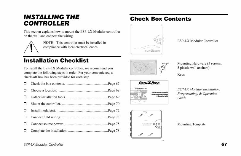
Check Box Contents
ESP-LX Modular Controller
Mounting Hardware (5 screws, 5 plastic wall anchors)
Keys
ESP-LX Modular Installation, Programming, & Operation Guide
Mounting Template
68 ESP-LX Modular Controller
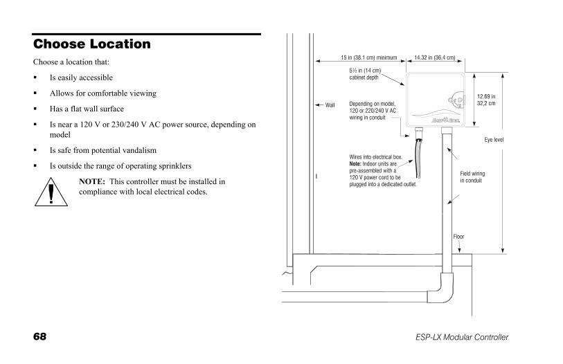
Choose Location Choose a location that:
Is easily accessible
Allows for comfortable viewing
Has a flat wall surface
Is near a 120 V or 230/240 V AC power source, depending on model
Is safe from potential vandalism
Is outside the range of operating sprinklers
NOTE: This controller must be installed in compliance with local electrical codes.
ESP-LX Modular Controller 69
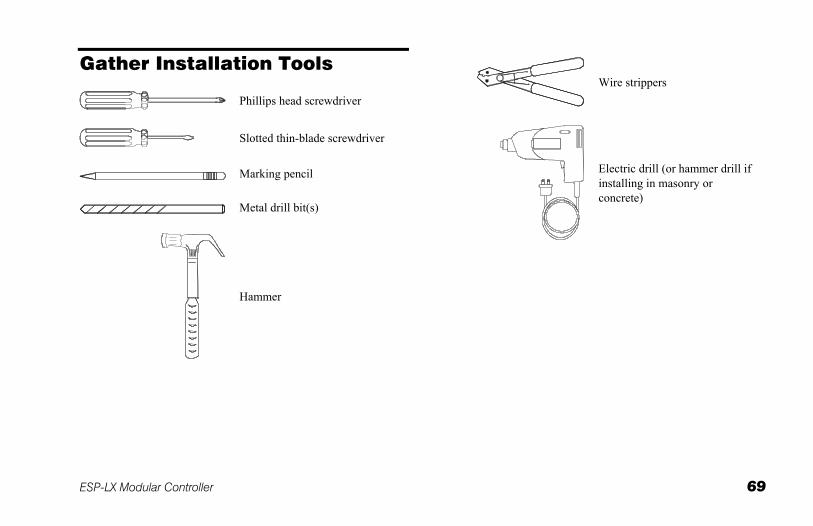
Gather Installation Tools
Phillips head screwdriver
Slotted thin-blade screwdriver
Marking pencil
Metal drill bit(s)
Hammer
Wire strippers
Electric drill (or hammer drill if installing in masonry or concrete)
70 ESP-LX Modular Controller
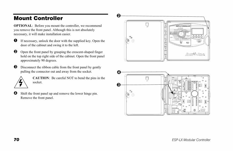
Mount Controller OPTIONAL: Before you mount the controller, we recommend you remove the front panel. Although this is not absolutely necessary, it will make installation easier.
If necessary, unlock the door with the supplied key. Open the door of the cabinet and swing it to the left.
Open the front panel by grasping the crescent-shaped finger hold on the top right side of the cabinet. Open the front panel approximately 90 degrees.
Disconnect the ribbon cable from the front panel by gently pulling the connector out and away from the socket.
CAUTION: Be careful NOT to bend the pins in the socket.
Shift the front panel up and remove the lower hinge pin. Remove the front panel.
ESP-LX Modular Controller 71
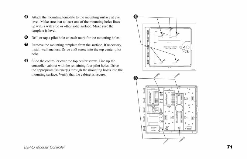
Attach the mounting template to the mounting surface at eye level. Make sure that at least one of the mounting holes lines up with a wall stud or other solid surface. Make sure the template is level.
Drill or tap a pilot hole on each mark for the mounting holes.
Remove the mounting template from the surface. If necessary, install wall anchors. Drive a #8 screw into the top center pilot hole.
Slide the controller over the top center screw. Line up the controller cabinet with the remaining four pilot holes. Drive the appropriate fastener(s) through the mounting holes into the mounting surface. Verify that the cabinet is secure.
72 ESP-LX Modular Controller
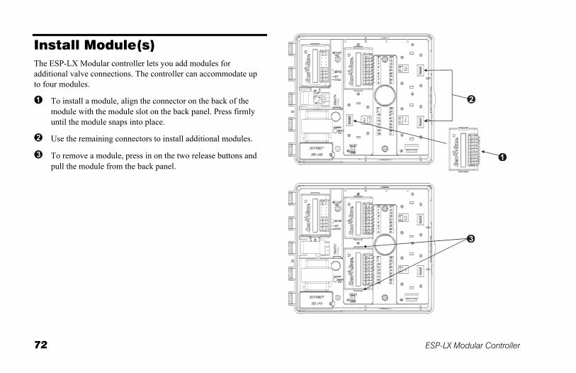
Install Module(s) The ESP-LX Modular controller lets you add modules for additional valve connections. The controller can accommodate up to four modules.
To install a module, align the connector on the back of the module with the module slot on the back panel. Press firmly until the module snaps into place.
Use the remaining connectors to install additional modules.
To remove a module, press in on the two release buttons and pull the module from the back panel.
ESP-LX Modular Controller 73
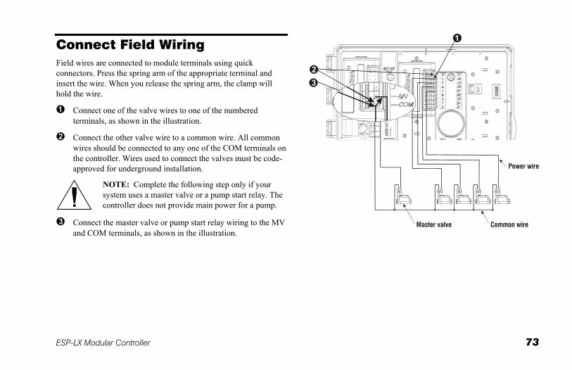
Connect Field Wiring Field wires are connected to module terminals using quick connectors. Press the spring arm of the appropriate terminal and insert the wire. When you release the spring arm, the clamp will hold the wire.
Connect one of the valve wires to one of the numbered terminals, as shown in the illustration.
Connect the other valve wire to a common wire. All common wires should be connected to any one of the COM terminals on the controller. Wires used to connect the valves must be code-approved for underground installation.
NOTE: Complete the following step only if your system uses a master valve or a pump start relay. The controller does not provide main power for a pump.
Connect the master valve or pump start relay wiring to the MV and COM terminals, as shown in the illustration.
74 ESP-LX Modular Controller
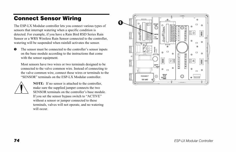
Connect Sensor Wiring The ESP-LX Modular controller lets you connect various types of sensors that interrupt watering when a specific condition is detected. For example, if you have a Rain Bird RSD Series Rain Sensor or a WRS Wireless Rain Sensor connected to the controller, watering will be suspended when rainfall activates the sensor.
The sensor must be connected to the controller’s sensor inputs on the base module according to the instructions that come with the sensor equipment.
Most sensors have two wires or two terminals designed to be connected to the valve common wire. Instead of connecting to the valve common wire, connect these wires or terminals to the “SENSOR” terminals on the ESP-LX Modular controller.
NOTE: If no sensor is attached to the controller, make sure the supplied jumper connects the two SENSOR terminals on the controller’s base module. If you set the sensor bypass switch to “ACTIVE” without a sensor or jumper connected to these terminals, valves will not operate, and no watering will occur.
ESP-LX Modular Controller 75
Connect Source Power
WARNING: To prevent electrical shock, make sure all supply power is OFF before connecting these wires. Electrical shock can cause severe injury or death.
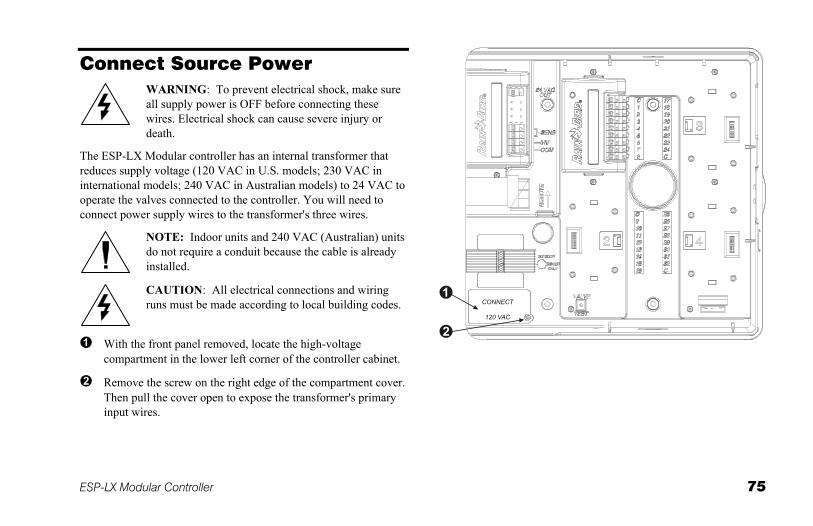
The ESP-LX Modular controller has an internal transformer that reduces supply voltage (120 VAC in U.S. models; 230 VAC in international models; 240 VAC in Australian models) to 24 VAC to operate the valves connected to the controller. You will need to connect power supply wires to the transformer's three wires.
NOTE: Indoor units and 240 VAC (Australian) units do not require a conduit because the cable is already installed.
CAUTION: All electrical connections and wiring runs must be made according to local building codes.
With the front panel removed, locate the high-voltage compartment in the lower left corner of the controller cabinet.
Remove the screw on the right edge of the compartment cover. Then pull the cover open to expose the transformer's primary input wires.
76 ESP-LX Modular Controller
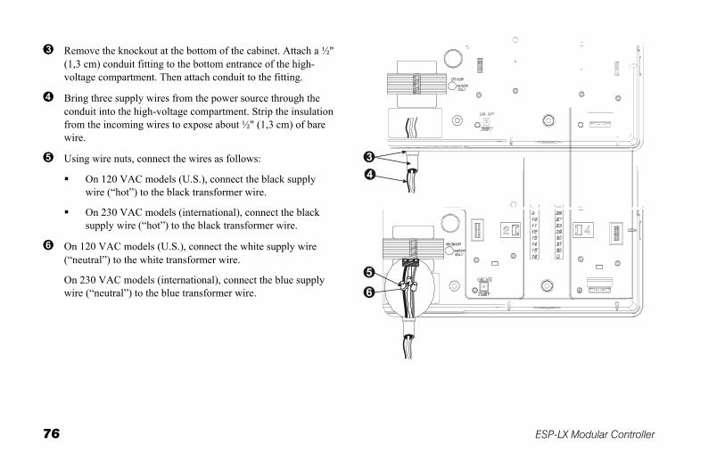
Remove the knockout at the bottom of the cabinet. Attach a ½" (1,3 cm) conduit fitting to the bottom entrance of the high-voltage compartment. Then attach conduit to the fitting.
Bring three supply wires from the power source through the conduit into the high-voltage compartment. Strip the insulation from the incoming wires to expose about ½" (1,3 cm) of bare wire.
Using wire nuts, connect the wires as follows:
On 120 VAC models (U.S.), connect the black supply wire (“hot”) to the black transformer wire.
On 230 VAC models (international), connect the black supply wire (“hot”) to the black transformer wire.
On 120 VAC models (U.S.), connect the white supply wire (“neutral”) to the white transformer wire.
On 230 VAC models (international), connect the blue supply wire (“neutral”) to the blue transformer wire.
ESP-LX Modular Controller 77
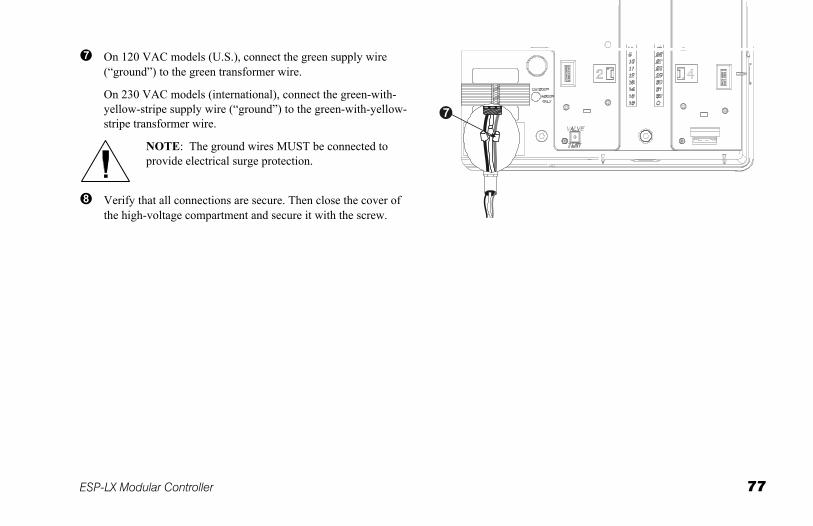
On 120 VAC models (U.S.), connect the green supply wire (“ground”) to the green transformer wire.
On 230 VAC models (international), connect the green-with-yellow-stripe supply wire (“ground”) to the green-with-yellow-stripe transformer wire.
NOTE: The ground wires MUST be connected to provide electrical surge protection.
Verify that all connections are secure. Then close the cover of the high-voltage compartment and secure it with the screw.
78 ESP-LX Modular Controller
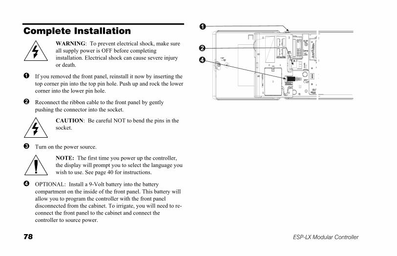
Complete Installation
WARNING: To prevent electrical shock, make sure all supply power is OFF before completing installation. Electrical shock can cause severe injury or death.
If you removed the front panel, reinstall it now by inserting the top corner pin into the top pin hole. Push up and rock the lower corner into the lower pin hole.
Reconnect the ribbon cable to the front panel by gently pushing the connector into the socket.
CAUTION: Be careful NOT to bend the pins in the socket.
Turn on the power source.
NOTE: The first time you power up the controller, the display will prompt you to select the language you wish to use. See page 40 for instructions.
OPTIONAL: Install a 9-Volt battery into the battery compartment on the inside of the front panel. This battery will allow you to program the controller with the front panel disconnected from the cabinet. To irrigate, you will need to re-connect the front panel to the cabinet and connect the controller to source power.
ESP-LX Modular Controller 79
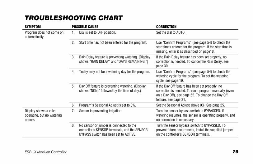
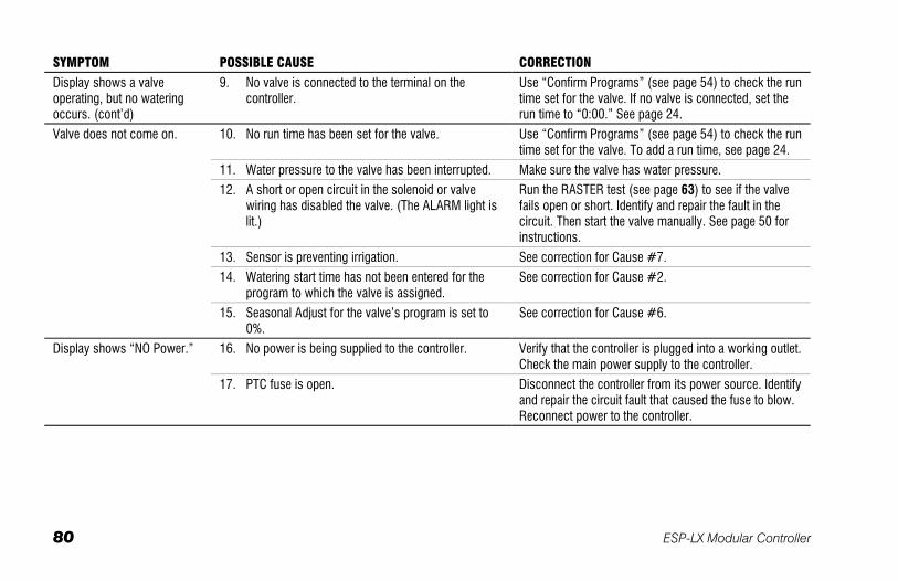
TROUBLESHOOTING CHART SYMPTOM POSSIBLE CAUSE CORRECTION
Program does not come on automatically.
1. Dial is set to OFF position. Set the dial to AUTO.
2. Start time has not been entered for the program. Use “Confirm Programs” (see page 54) to check the start times entered for the program. If the start time is missing, enter it as described on page18.
3. Rain Delay feature is preventing watering. (Display shows “RAIN DELAY” and “DAYS REMAINING.”)
If the Rain Delay feature has been set properly, no correction is needed. To cancel the Rain Delay, see page 30.
4. Today may not be a watering day for the program. Use “Confirm Programs” (see page 54) to check the watering cycle for the program. To set the watering cycle, see page 19.
5. Day Off feature is preventing watering. (Display shows “NON,” followed by the time of day.)
If the Day Off feature has been set properly, no correction is needed. To run a program manually (even on a Day Off), see page 52. To change the Day Off feature, see page 31.
6. Program’s Seasonal Adjust is set to 0%. Set the Seasonal Adjust above 0%. See page 25.
Display shows a valve operating, but no watering occurs.
7. Sensor is preventing irrigation. Turn the sensor bypass switch to BYPASSED. If watering resumes, the sensor is operating properly, and no correction is necessary.
8. No sensor or jumper is connected to the controller’s SENSOR terminals, and the SENSOR BYPASS switch has been set to ACTIVE.
Turn the sensor bypass switch to BYPASSED. To prevent future occurrences, install the supplied jumper on the controller’s SENSOR terminals.
80 ESP-LX Modular Controller
SYMPTOM POSSIBLE CAUSE CORRECTION
Display shows a valve operating, but no watering occurs. (cont’d)
9. No valve is connected to the terminal on the controller.
Use “Confirm Programs” (see page 54) to check the run time set for the valve. If no valve is connected, set the run time to “0:00.” See page 24.
Valve does not come on. 10. No run time has been set for the valve. Use “Confirm Programs” (see page 54) to check the run time set for the valve. To add a run time, see page 24.
11. Water pressure to the valve has been interrupted. Make sure the valve has water pressure.
12. A short or open circuit in the solenoid or valve wiring has disabled the valve. (The ALARM light is lit.)
Run the RASTER test (see page 63) to see if the valve fails open or short. Identify and repair the fault in the circuit. Then start the valve manually. See page 50 for instructions.
13. Sensor is preventing irrigation. See correction for Cause #7.
14. Watering start time has not been entered for the program to which the valve is assigned.
See correction for Cause #2.
15. Seasonal Adjust for the valve’s program is set to 0%.
See correction for Cause #6.
Display shows “NO Power.” 16. No power is being supplied to the controller. Verify that the controller is plugged into a working outlet. Check the main power supply to the controller.
17. PTC fuse is open. Disconnect the controller from its power source. Identify and repair the circuit fault that caused the fuse to blow. Reconnect power to the controller.
ESP-LX Modular Controller 81
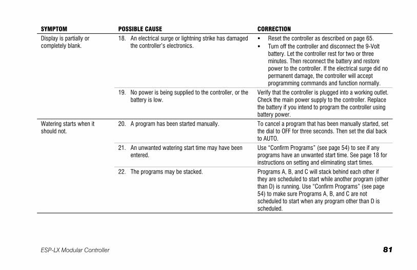
SYMPTOM POSSIBLE CAUSE CORRECTION
Display is partially or completely blank.
18. An electrical surge or lightning strike has damaged the controller’s electronics.
Reset the controller as described on page 65. Turn off the controller and disconnect the 9-Volt
battery. Let the controller rest for two or three minutes. Then reconnect the battery and restore power to the controller. If the electrical surge did no permanent damage, the controller will accept programming commands and function normally.
19. No power is being supplied to the controller, or the battery is low.
Verify that the controller is plugged into a working outlet. Check the main power supply to the controller. Replace the battery if you intend to program the controller using battery power.
Watering starts when it should not.
20. A program has been started manually. To cancel a program that has been manually started, set the dial to OFF for three seconds. Then set the dial back to AUTO.
21. An unwanted watering start time may have been entered.
Use “Confirm Programs” (see page 54) to see if any programs have an unwanted start time. See page 18 for instructions on setting and eliminating start times.
22. The programs may be stacked. Programs A, B, and C will stack behind each other if they are scheduled to start while another program (other than D) is running. Use “Confirm Programs” (see page 54) to make sure Programs A, B, and C are not scheduled to start when any program other than D is scheduled.
82 ESP-LX Modular Controller
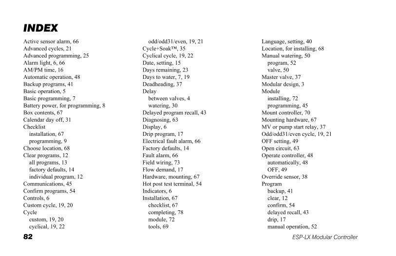
INDEX Active sensor alarm, 66 Advanced cycles, 21 Advanced programming, 25 Alarm light, 6, 66 AM/PM time, 16 Automatic operation, 48 Backup programs, 41 Basic operation, 5 Basic programming, 7 Battery power, for programming, 8 Box contents, 67 Calendar day off, 31 Checklist
installation, 67 programming, 9
Choose location, 68 Clear programs, 12
all programs, 13 factory defaults, 14 individual program, 12
Communications, 45 Confirm programs, 54 Controls, 6 Custom cycle, 19, 20 Cycle
custom, 19, 20 cyclical, 19, 22
odd/odd31/even, 19, 21 Cycle+Soak™, 35 Cyclical cycle, 19, 22 Date, setting, 15 Days remaining, 23 Days to water, 7, 19 Deadheading, 37 Delay
between valves, 4 watering, 30
Delayed program recall, 43 Diagnosing, 63 Display, 6 Drip program, 17 Electrical fault alarm, 66 Factory defaults, 14 Fault alarm, 66 Field wiring, 73 Flow demand, 17 Hardware, mounting, 67 Hot post test terminal, 54 Indicators, 6 Installation, 67
checklist, 67 completing, 78 module, 72 tools, 69
Language, setting, 40 Location, for installing, 68 Manual watering, 50
program, 52 valve, 50
Master valve, 37 Modular design, 3 Module
installing, 72 programming, 45
Mount controller, 70 Mounting hardware, 67 MV or pump start relay, 37 Odd/odd31/even cycle, 19, 21 OFF setting, 49 Open circuit, 63 Operate controller, 48
automatically, 48 OFF, 49
Override sensor, 38 Program
backup, 41 clear, 12 confirm, 54 delayed recall, 43 drip, 17 manual operation, 52
ESP-LX Modular Controller 83
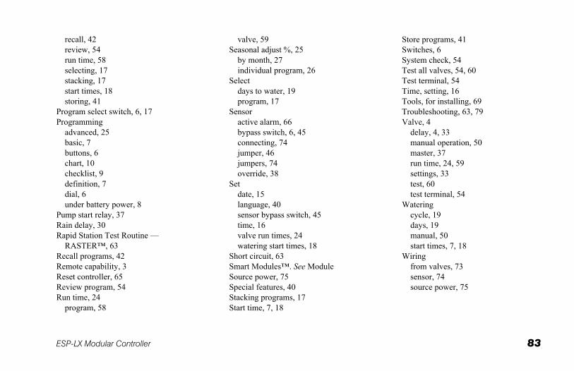
recall, 42 review, 54 run time, 58 selecting, 17 stacking, 17 start times, 18 storing, 41
Program select switch, 6, 17 Programming
advanced, 25 basic, 7 buttons, 6 chart, 10 checklist, 9 definition, 7 dial, 6 under battery power, 8
Pump start relay, 37 Rain delay, 30 Rapid Station Test Routine —
RASTER™, 63 Recall programs, 42 Remote capability, 3 Reset controller, 65 Review program, 54 Run time, 24
program, 58
valve, 59 Seasonal adjust %, 25
by month, 27 individual program, 26
Select days to water, 19 program, 17
Sensor active alarm, 66 bypass switch, 6, 45 connecting, 74 jumper, 46 jumpers, 74 override, 38
Set date, 15 language, 40 sensor bypass switch, 45 time, 16 valve run times, 24 watering start times, 18
Short circuit, 63 Smart Modules™. See Module Source power, 75 Special features, 40 Stacking programs, 17 Start time, 7, 18
Store programs, 41 Switches, 6 System check, 54 Test all valves, 54, 60 Test terminal, 54 Time, setting, 16 Tools, for installing, 69 Troubleshooting, 63, 79 Valve, 4
delay, 4, 33 manual operation, 50 master, 37 run time, 24, 59 settings, 33 test, 60 test terminal, 54
Watering cycle, 19 days, 19 manual, 50 start times, 7, 18
Wiring from valves, 73 sensor, 74 source power, 75
84 ESP-LX Modular Controller

NOTES
This equipment has been tested and found to comply with the limits for a Class B digital device, pursuant to Part 15 of the FCC Rules. These limits are designed to provide reasonable protection against harmful interference in a residential installation.
This equipment generates, uses, and can radiate radio frequency energy and, if not installed and used in accordance with the instructions, may cause harmful interference to radio communications. However, there is no guarantee that interference will not occur in a particular installation.
If the equipment does cause harmful interference to radio or television reception, which can be determined by turning the equipment off and on, the user is encouraged to try to correct the interference by the following measures:
• Reorient or relocate the receiving antenna.
• Increase the separation between the equipment and receiver.
• Connect the equipment into an outlet on a circuit different from that to which the receiver is connected.
• Consult the dealer or an experienced radio/TV technician for help.
Changes or modifications not expressly approved by Rain Bird Sales, Inc., could void the user’s authority to operate the equipment.
This product was FCC certified under test conditions that included the use of shielded I/O cables and connectors between system components. To be in compliance with FCC regulations, the user must use shielded cables and connectors and install them properly.
RAIN BIRD CORPORATION 6991 E. Southpoint Road, Bldg. 1 • Tucson, AZ 85706
Rain Bird Europe, S.A.R.L. • 900, rue Ampere • BP 72000 • 13792 Aix en Provence Cedex 3 • France © 2006 Rain Bird Corporation
® Registered trademark of Rain Bird Corporation. • ® Marca registrada de Rain Bird Corporation. www.rainbird.com
636281-010 Rev A