esp
DESCRIPTION
espTRANSCRIPT
• What is ESP?• Need of ESP• Components of ESP• Construction• Schematic Diagram• Basic Principle• Performance of ESP• Technical Specifications• Photos
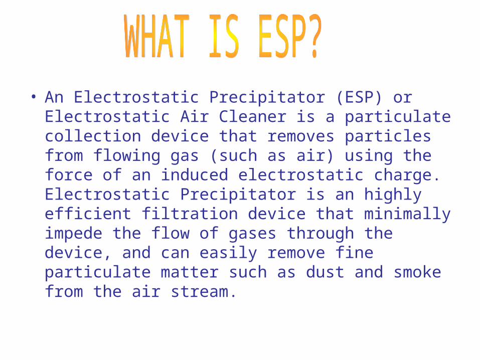
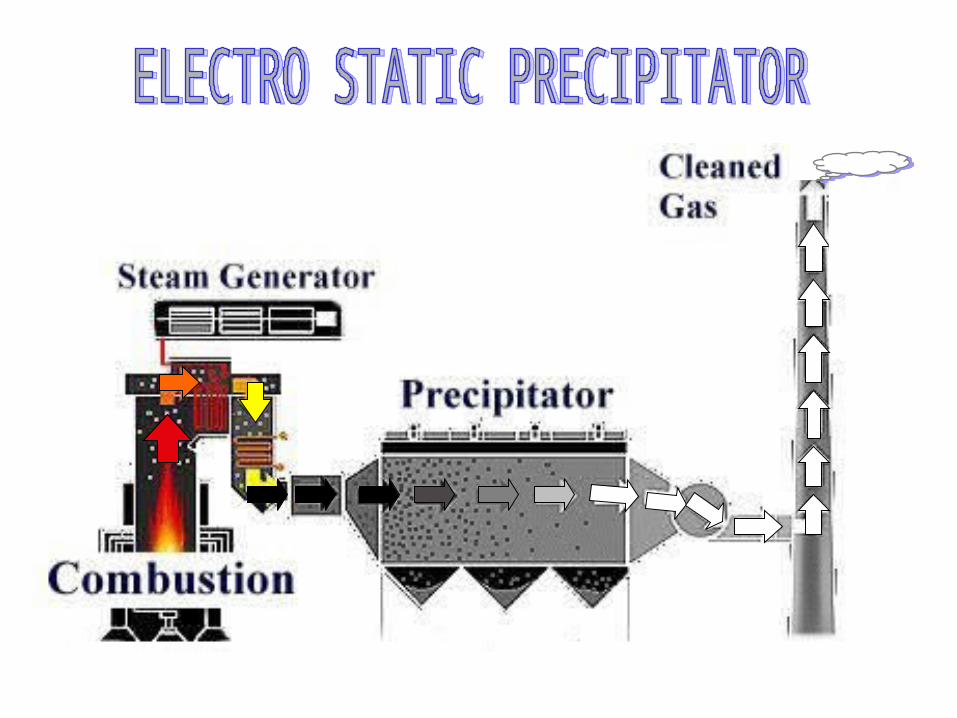
• An Electrostatic Precipitator (ESP) or Electrostatic Air Cleaner is a particulate collection device that removes particles from flowing gas (such as air) using the force of an induced electrostatic charge. Electrostatic Precipitator is an highly efficient filtration device that minimally impede the flow of gases through the device, and can easily remove fine particulate matter such as dust and smoke from the air stream.
• Many countries around the world, including our own, depend on coal and other fossil fuels to produce electricity. A natural result from the burning of fossils fuels,particularly coal is the emission of fly ash. Ash is mineral matter present in the fuel. For a pulverised coal unit,40-50% of ash leaves with the flue gas.

• Contd.• Fly ash emission have received the greatest
attention since they are easily seen leaving smoke stacks. If that much amount of ash is released in the atmosphere it will adversely affect the environment. When flue gas enters in the ESP, Ash particles are deposited on the collecting plates and only clean gas is released to atmosphere.
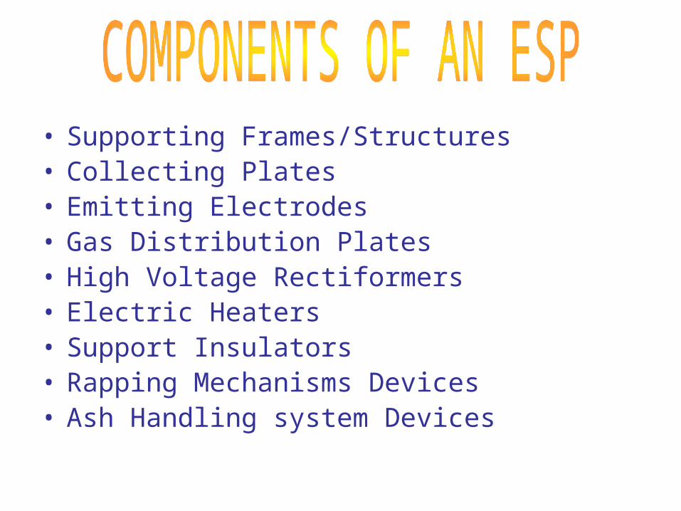
• Supporting Frames/Structures• Collecting Plates• Emitting Electrodes• Gas Distribution Plates• High Voltage Rectiformers• Electric Heaters• Support Insulators• Rapping Mechanisms Devices• Ash Handling system Devices

- - - - - - - - - - - - - - - - -- - - - - - - - - - - - - - - - - -- - - - - - - - - - - - - - - - - -- - - - - - - - - - - - - - - - - -- - - - - - - - - - - - - - - - - -- - - - - - - - - - - - - - - - - -- - - - - - - - - - - - - - - -
-
- -
- -
- -
- -
- -
- -
- -
- -
-
- -
- -
- -
- -
- -
- -
- -
- -
INLET OUTLET
EMITTING ELECTRODE
COLLECTING ELECTRODE
GAS SEALS
FLUE GAS TROUGH ESP
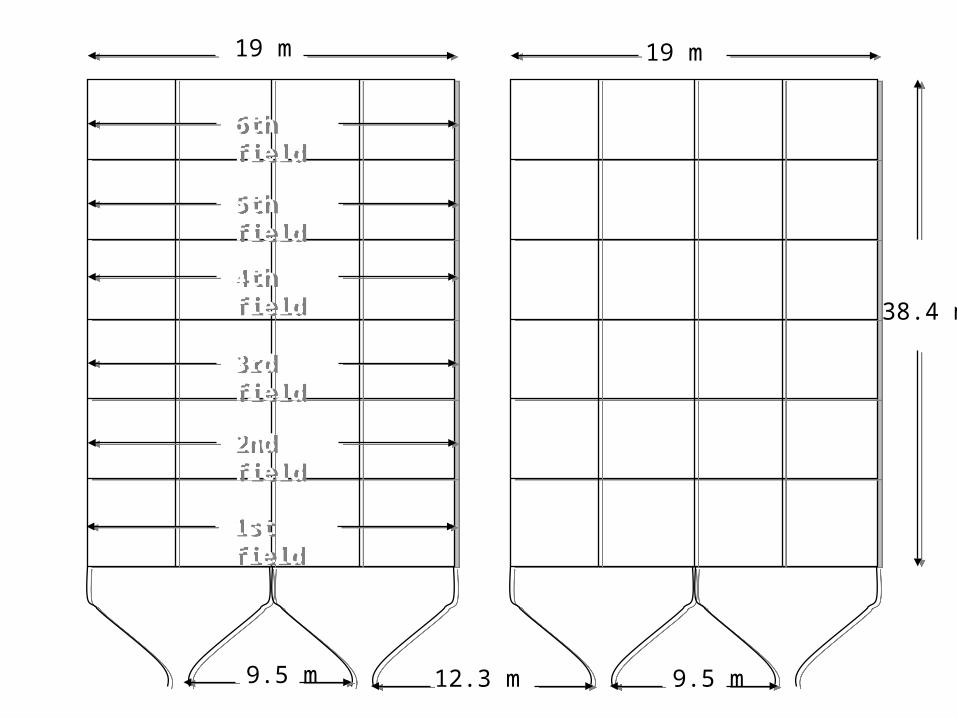
19 m 19 m
38.4 m
12.3 m 9.5 m 9.5 m
1st field1st field
2nd field2nd field
3rd field3rd field
4th field4th field
5th field5th field
6th field6th field


HVR
SCHEMATIC DIAGRAM OF ELECTRIC CIRCUIT OF ESP
( + ) VE
( - ) VE
Collecting
electrode
emitting
electrode

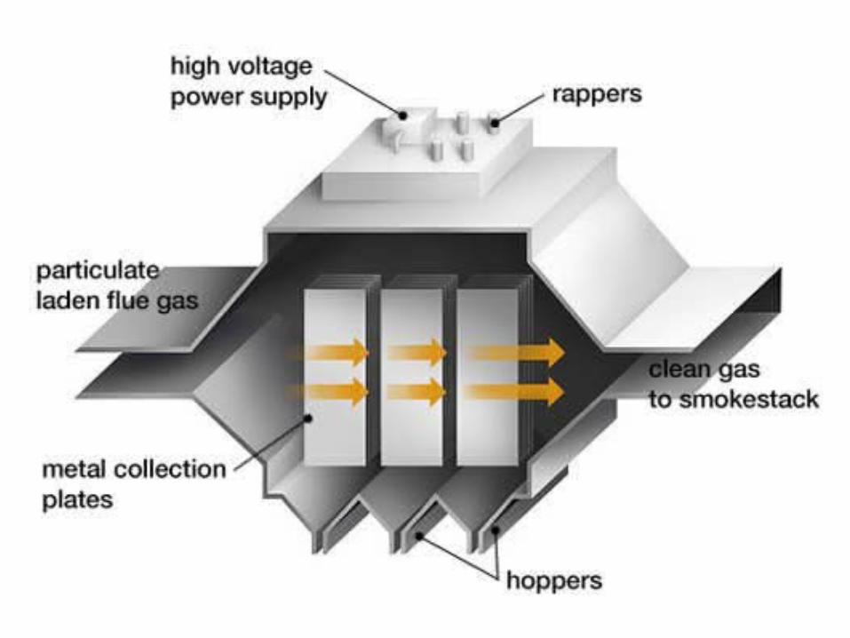
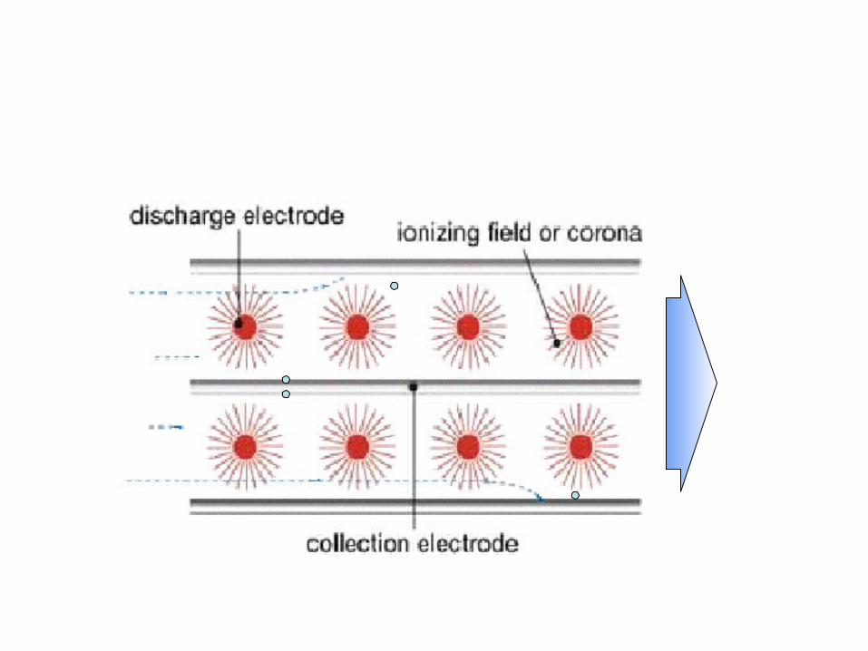
• The principal components of an ESP are two sets of electrodes insulated from each other. The first set is composed of row of electrically grounded vertical parallel plates, called the collection electrodes, between which the dust laden gas flows. The second set of electrodes consists of wires, called the discharge or emitting electrodes that are centrally located between each pairs of parallel plates. The wires carry a unidirectional negatively charged high voltage current from an external dc source. The applied high voltage generated a unidirectional, non uniform electrical field whose magnitude is greater near the discharge electrodes. When that voltage is high enough, a blue luminous glow, called a corona, is produced around them. Electrical forces in the corona accelerate, thus forming more electrons & positive gas ions. The new electrons create again more free electrons & ions, which result in a chain reaction.
• Contd.• The positive ions travel to the negatively charged wire electrodes.
The electrons follow the electrical field toward the grounded electrodes, but their velocity decreases as they move away from the corona region around the wire electrodes towards the grounded plates. Gas molecules capture the low velocity electrons & become negative ions. As these ions move to the collecting electrode, they collide with the fly ash particles in the gas stream & give them negative charge. The negatively charge fly ash particles are driven to the collecting plate by the force which is proportional to the product of the charge & the strength of the electric field.
• When the particles collect on the grounded plates, they lose their charge on the ground.


• Performance of ESP depends upon particle properties (density,electrical resistivity,size distribution),Construction and Geometrical parameters (electrode type & shape,space between the plates & electrodes etc.), and Operational variables (applied potencial,cleaning frequency etc.)

η = 1- exp(-A*Vm/Q)
Where A= collecting plate area.
Vm = Flue gas migration velocity
Q = discharge rate of flue gas

TYPE 1 Set of 4-horizontal chamber & 6 fields.
TYPE OF EMITTING ELECTRODS RSB wires for field 1-4
Spiral wires for field 5-6
FLUE GAS VOLUME 1668404 m3/h
FLUE GAS TEMPRETURE 125-160.C
TOTAL SURFACE AREA FOR COLLECTING PLATES
96489 m2
GAS VELOCITY 0.858 m/sec.
DISTANCE BETWEEN COLLECTING PLATES
300mm. for field 1-4
& 400mm for field 5-6.
HV POWER SUPPLY EQUIPMENT 24 no. (16 nos. of 60 kV & 8 nos. of 72 kV)
NO. OF HOPPERS 48
MIGRATION VELOCITY 3.95 cm/sec.
COLLECTING EFFICIENCY 99.97%

ESP – BEST SUITED FOR INDIAN CONDITION Reliable and proven technology in Indian
conditions Suitable for prolonged oil firing at low loads Can effectively handle large quantities of
abrasive type fly ash without any operating problems
Not sensitive with high flue gas temperatures with respect to life of ESP
Very low operating pressure drop Less maintenance

ASH HANDLING SYSTEM
• In the coal fired boiler 20% of the total ash is collected in the bottom ash hoppers.
• 3% in the eco hoppers • And 77% will be carried away by flue gas
which is called as fly ash. • As the flue gas passes through ESP fields,
fly ash will be collected in the ESP hoppers.• These hoppers are to be emptied regularly
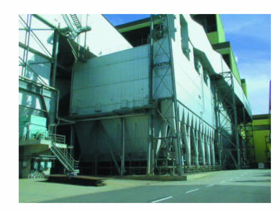
by means of vacuum evacuation system.