ess air cannon i4 / i6 · ess air cannons are pressure vessels with an attached valve mechanism...
TRANSCRIPT

ESS i4 i6 Air Cannon Manual 1 25/01/2019
–––
ESS Air Cannon i4 / i6
Installation and Operations Manual

ESS i4 i6 Air Cannon Manual 2 25/01/2019
Office Details
Location Address Phone & Email
CURRUMBIN
11 – 13 Traders Way PO Box 121 Currumbin QLD 4223
(07) 5589 2000
EMERALD
6/14 Esmond Street PO Box 1861 Emerald QLD 4720
(07) 4982 4855
GLADSTONE
Unit 2/34 Chapple Street PO Box 1475 Gladstone QLD 4680
(07) 4972 3759
KALGOORLIE
Unit A 255 Dugan St Kalgoorlie WA 6430 PO Box 10471 Kalgoorlie WA 6433
(08) 9021 7991
KARRATHA
26 Midas Road Malaga WA 6090
(08) 9248 4111
MACKAY
1 Progress Street Paget, QLD 4740 PO Box 5755 Mackay Mail Centre QLD 4741
(07) 4952 4600
MAITLAND
Unit 2 Barton Court 6 Johnson Street Maitland NSW 2320
(02) 4932 3544
PERTH
26 Midas Road Malaga WA 6090
(08) 9248 4111
TOWNSVILLE
Unit 4/ 585 Ingham Rd Mt St John Townsville QLD 4818
(07) 4952 4600
SOUTH AUSTRALIA
Unit 11/36 Tikalara St Regency Park SA 5010 Postal: 38 Montpelier Terrace Port Elliot SA 5212
0408 948 175
VICTORIA
Unit 4 / 314 Governor Road Braeside VIC 3195
(03) 9587 3979
WOLLONGONG
Unit 1 / 20 Doyle Avenue PO Box 343 Unanderra NSW 2526
(02) 4272 4422
TOLL FREE 1800 074 446 FROM ANYWHERE IN AUSTRALIA VSS TOLL FREE 1800 300 877

ESS i4 i6 Air Cannon Manual 3 25/01/2019
WARRANTY NOTE
ESS WARRANTS the ESS Air Cannon to be free of defects both in materials and workmanship for a period of 12 months from the date of despatch of the product from the ESS factory. The warranty given by ESS in this regard will extend only to replacing or repairing product shown to be defective. The warranty also is subject to the following restrictions: (a) Installation of the product contrary to the instructions contained in the supplied manual will void such
warranty absolutely; (b) The warranty will not extend to any liability for injuries incurred and which result from the use of the
product contrary to the instructions in the manual; (c) Save as prescribed by law, ESS will not be liable for any damage sustained by a purchaser or a third
party by way of consequential loss arising out of defects in the product. You are asked to note that ESS offers purchasers a service whereby either: (a) It will install the product and certify the correctness of such installation, or (b) Certify the correctness or otherwise of the installation of the product by third parties. This certification service is designed to ensure that you obtain the full benefit of the ESS warranty hereby provided. If you would like to take advantage of the installation certification service provided, please contact ESS regarding the service. Refer to the Final Checklist at the back of this manual. Visit the ESS website www.esseng.com.au to register your product warranty. THE CONTENTS OF THIS MANUAL ARE COPYRIGHT TO: ESS ENGINEERING SERVICES AND SUPPLIES PTY LTD ALL RIGHTS RESERVED Information contained herein is for use in the operation of ESS Air Cannon, purchased from ESS and cannot be passed on to any other party without express permission, in writing, from ESS.

ESS i4 i6 Air Cannon Manual 4 25/01/2019
Contents
SECTION I - INTRODUCTION .................................................................................................................................................. 6
What is an Air Cannon? ..................................................................................................................................................... 7 Applications: ...................................................................................................................................................................... 7 Safety Precautions: ............................................................................................................................................................ 8
SECTION II - AIR CANNON OPERATION ................................................................................................................................. 9
General Overview - How the Air Cannon Works: .............................................................................................................. 9
Option 1 – Fill-on-demand (trigger-fill) - ....................................................................................................................... 9 Option 2 – Pressure-Maintained (trigger-fire) - .......................................................................................................... 11 Air Requirements:........................................................................................................................................................ 12 Air Filtration: ................................................................................................................................................................ 12 Maintenance: See SECTION V - MAINTENANCE on Page 29 ...................................................................................... 12 When to “Fire” the Air Cannon: .................................................................................................................................. 12 Quick Exhaust Valve: ................................................................................................................................................... 12
Required Accessories: ..................................................................................................................................................... 12
SECTION III - INSTALLATION ................................................................................................................................................ 14
Preparation and Background: ......................................................................................................................................... 14
Air Cannon Placement ................................................................................................................................................. 14 Bulk Material Types: .................................................................................................................................................... 14 Aiming the Air Blast: .................................................................................................................................................... 17 Air Cannon Orientation ............................................................................................................................................... 18 Required Storage Structure Wall Thickness: ............................................................................................................... 18 High Temperature Applications: ................................................................................................................................. 19 Air Cannon Air Supply Components ............................................................................................................................ 19 Visual Inspection: ........................................................................................................................................................ 19 Temporary Plug Removal: ........................................................................................................................................... 19
Installing Transition Pipes: .............................................................................................................................................. 20 Mounting to the Chute Wall: .......................................................................................................................................... 20
Mounting a Fanjet Nozzle: .......................................................................................................................................... 21 Mounting a 90 degree Fanjet: ..................................................................................................................................... 21
Mounting the Air Cannon to the Discharge Pipe: ........................................................................................................... 22 Air Supply & Control - Component Installation: .............................................................................................................. 23
Option 1 - Arrangement: ............................................................................................................................................. 24 Option 2 - Arrangement: ............................................................................................................................................. 25 Quick Exhaust Valve Installation (Option 2): ............................................................................................................... 26
Air Supply - Overall Arrangement ................................................................................................................................... 27
SECTION IV - AIR CANNON START-UP PROCEDURES .......................................................................................................... 28 SECTION V - MAINTENANCE ............................................................................................................................................... 29
Lubrication: ...................................................................................................................................................................... 29 Air Control Accessories .................................................................................................................................................... 29
Quick Exhaust Valve: ................................................................................................................................................... 29 Air Cannon Mounting: ................................................................................................................................................. 29

ESS i4 i6 Air Cannon Manual 5 25/01/2019
Air Cannon Internal Valve: .......................................................................................................................................... 29 Spare Parts Recommendations: .................................................................................................................................. 29 Pressure Vessel Inspection: ......................................................................................................................................... 29
SECTION VI - DIS/ASSEMBLY OF THE AIR CANNON ............................................................................................................ 30
Replacing the Quick Exhaust Valve Exhaust Port Bands: ................................................................................................ 30 Dismounting the Air Cannon: .......................................................................................................................................... 31 Removing the Internal Valve: .......................................................................................................................................... 32 Valve Disassembly: .......................................................................................................................................................... 34 Valve Inspection: ............................................................................................................................................................. 34 Assembling the Valve: ..................................................................................................................................................... 35 Assembling the Air Cannon: ............................................................................................................................................ 37
APPENDIX A - TROUBLESHOOTING ..................................................................................................................................... 38 APPENDIX B – Assembly Drawings ...................................................................................................................................... 39
40L i4 – Exploded Drawing .............................................................................................................................................. 39 70L i4 – Exploded Drawing .............................................................................................................................................. 40 70L i6 – Exploded Drawing .............................................................................................................................................. 41 150L i6 – Exploded Drawing ............................................................................................................................................ 42 150L i6 “Epsilon” – Exploded Drawing ............................................................................................................................ 43 I4 Internal Valve – Exploded Drawing ............................................................................................................................. 44 I6 Internal Valve – Exploded Drawing ............................................................................................................................. 45 Quick Exhaust Valve – Exploded Drawing ....................................................................................................................... 46 Air Cannons – Installation Detail ..................................................................................................................................... 47 Option 1 Arrangement – Normally Closed ...................................................................................................................... 48 Option 2 Arrangement – Normally Open ........................................................................................................................ 49
APPENDIX C – Recommended Spares ................................................................................................................................. 50 APPENDIX D – Air Cannon Data Sheet ................................................................................................................................. 52 SECTION 7- FINAL CHECKLIST .............................................................................................................................................. 53

ESS i4 i6 Air Cannon Manual 6 25/01/2019
SECTION I - INTRODUCTION
This manual will assist in the installation and operation of ESS’ i4 (internal-4inch) and i6 (internal-6 inch) Air Cannons. Please read the entire manual to assure proper installation, operation, and maintenance of this equipment. These instructions apply to the following models, from left to right:
Safety Instructions
Pictograph labels are used to show graphically where potential safety hazards exist around this Air Cannon. These labels do not represent every possible hazard. They are not intended to be a substitute for safe work practices and good judgment. These labels and the technical manuals supplied with the Air Cannon, use specific words to identify the severity of the hazard. They are described below. Take time to read and understand the meaning of these words and symbols.
Danger labels call attention to imminently hazardous situations that will result in serious personal injury or death if not avoided. Injury from these hazards is immediate in nature and has a high probability of resulting in a serious or fatal accident if proper precautions are not followed. Warning labels call attention to potentially hazardous situations that could result in serious personal injury or death if not avoided. Injury from these hazards is usually serious in nature, and a severe or fatal accident can occur if proper precautions are not followed. Caution labels call attention to potentially hazardous situations that may result in minor or moderate personal injury if not avoided. Injury from these hazards is normally less serious than those from Danger or Warning hazards. However, there is still the potential for an accident resulting in serious injury if proper precautions are not followed.
50511506 150L i6
50510756 70L i6 50510754 70L i4
50510404 40L i4
50511516 150L i6 “EPSILON”
6 inch internal valve 4 inch internal valve

ESS i4 i6 Air Cannon Manual 7 25/01/2019
General
ESS Air Cannons are pressure vessels with an attached valve mechanism that is designed to discharge stored air at a very high velocity. The resultant air blast is used to dislodge adhering, bridging, or built-up bulk materials in bins, silos, and stockpiles. The air blast is directed to the required location via fully welded and secured blast pipework. On most applications, a number of Air Cannons will be utilised as a system approach to solving a material flow problem, with cannons firing in a determined sequence.
What is an Air Cannon?
ESS Air Cannons are direct blast aerators consisting of a compressed air reservoir with a quick opening valve that releases the stored air in a sudden, high energy blast. This blast is directed through a discharge pipe to restore material flow by aerating and dislodging material that is bridging, arching, rat holing, or clinging.
Bridging Arching Rat holing Clinging The direct blast design of the valve allows the stored air in the reservoir to escape directly through the valve into the discharge pipe without bends or obstructions that could impede the flow of air. This is important because the quicker the air discharges, the greater the velocity, impulse, and force of the blast and, therefore, the greater the amount of material affected. Air Cannons are activated remotely via a Sequence Controller which controls the firing time interval and sequence of one or more Air Cannons. ESS Engineering offers two valve sizes in their Air Cannons; a 4” (i4) and 6” (i6). These Air Cannons are rated for high temperature applications (ambient temperatures up to 119°C) such as cement kilns and steel mills where internal kiln temperatures can be as high as 1,100°C.
Applications:
Air Cannons easily solve bulk flow problems in silos, hoppers, chutes, and storage piles. They are used where vibration is not practical, or when other methods are too expensive, dangerous, or destructive. Air Cannons are recommended for a wide range of material clogs and jams, and are well suited for large structures of any type. They are commonly used when it is impractical to physically shake stuck material loose, and are effective for very cohesive, difficult materials. For instance, large concrete bunkers and storage piles on the ground are impossible to vibrate, but are common locations of flow problems. Wood chips are very difficult to dislodge by other means, but respond very well to the quick-release air impulse. Air Cannons are also used to periodically aerate material sitting in bins, hoppers, and silos since their blast will lift and separate the material rather than compact it.

ESS i4 i6 Air Cannon Manual 8 25/01/2019
Safety Precautions:
The air blast can exceed 300 m/sec and 680 kg of force. Be sure to read and follow all safety precautions.
Do not stand in front of any Air Cannon during discharge. The air blast can cause serious injury or death.
Use of an Air Cannon to shoot a projectile may cause serious injury or death.
ESS Air Cannon pressure vessels are AS 1210 designed, welded, and certified. Do not weld onto the pressure
vessel (tank). Welding to the tank will void AS 1210 certification and may cause vessel malfunction.
All WH&S, MDG and owner’s safety procedures and regulations must be followed during installation, operation, and maintenance of Air Cannons.
Do not discharge the Air Cannon into open air without clear warnings to all persons in the area.
The Air Cannons are LOUD. Do not discharge with nearby personnel without hearing protection. Doing so may cause permanent hearing damage.
All Air Cannons must be empty of air when being transported, mounted, or inspected.
Due to recoil, do not discharge an Air Cannon that is not securely mounted to a structure.
Mount the Air Cannon securely on Schedule 40 pipe or equivalent. If structure is not sufficiently rigid to support the Air Cannon, contact your ESS Representative to obtain special mount hardware.
Attach the lifting lug on the end of the Air Cannon tank to a structural support with a suspension kit to prevent the Air Cannon from falling if its supports were to give way.
Do not enter application structure (i.e. bin or hopper) if Air Cannons are pressurized and ready to be discharged.
Do not allow the internal pressure in a closed storage vessel to exceed its limitations when the Air Cannons are
fired. This may cause damage to the storage vessel. Install exhaust vents if pressures exceed 0.03 bar. Generally, ESS will design so this will not be an issue. The momentary vessel pressure following the firing of an Air Cannon can be estimated as follows:
Pm = Air Cannon tank pressure (atm) x Air Cannon tank volume (litres) Air Cannon tank volume (litres) + Structure volume (litres)
ESS i4 and i6 series Air Cannons can withstand ambient temperatuers between -10°C and 119°C. Exposure to temperatures outside of this range this will cause the piston to seize. Damage caused by operating ESS i4 and i6 series Air Cannons at temperatures outside of this range are not covered by the product warranty.
For continued operation, operators must comply with the relevant Mines Safety Regulation, AS 3788 – Pressure Vessels - In-Service Inspection, or their own Risk Based Inspection (RBI) procedures.
- Do not remove air lines when tank is pressurised. Doing so may cause tank to fire. Always drain tank pressure from the tank itself via the pressure relief valve or ball valve.
Note

ESS i4 i6 Air Cannon Manual 9 25/01/2019
SECTION II - AIR CANNON OPERATION
General Overview - How the Air Cannon Works:
Two options of firing arrangements are available to choose from. These options are explained below.
Option 1 – Fill-on-demand (trigger-fill) - When the actuation signal is sent it causes the tank to begin filling, and when the actuation signal is removed the tank automatically fires. A remotely-actuated normally-closed 3-way pilot solenoid controls another 3-way normally-closed solenoid. In this arrangement, the tank will only fill when the actuation signal causes the pilot solenoid to open another 3-way normally closed solenoid. Referencing the figure below, without the actuation signal the air supply is unable to fill the tank. When the actuation signal is sent, the first normally-closed pilot solenoid is switched open to supply a pilot line that causes a tank-mounted solenoid to open, allowing the tank to fill. The colours are for indicative purposes only.
After the actuation signal sent from an automated PLC is removed, the pilot valve will close again, which in turn causes the tank-mounted valve to close/switch, causing the fill tube air to exhaust, and the cannon fires. This firing arrangement of Option 1 ensures that the tank fills when required, and the tank is not kept pressurised reducing the chance of a misfire if line pressure is lost. This also has the added benefit of reducing air consumption, as any air that could be lost due to leaks will no longer occur, and also air will be consumed by the tank only when needed which frees up available compressed air for other uses. This is ESS’ recommended option for air cannon control.
AIR SUPPLY

ESS i4 i6 Air Cannon Manual 10 25/01/2019
A step-by-step outline of the filling and discharging process follows:
1. An actuation signal is sent to the master pilot solenoid, which switches to open a pilot line to a second 3-way slaved solenoid, which allows plant air to enter the Air Cannon.
2. Plant air is forced out through the check valve in the quick exhaust valve cap to fill the pressure vessel with air. The pressure of the plant air ensures an air tight seal between the piston and seat, preventing any air loss while Air Cannon is waiting to be fired.
3. The actuation signal will automatically cease after a pre-set duration.
4. When the signal is removed, the pilot solenoid closes and exhausts the pilot line, which in turn closes the tank 3-way valve, so air in the tank’s internal fill tube is exhausted, causing the air pressure at the back of the piston to drop.
5. Due to the pressure differential created, the tank pressure forces the piston back into the open position.
6. The compressed air in the pressure vessel escapes through the discharge in an explosive blast that lifts and separates material particles, restoring material flow.
MAC solenoid valve models are available in different power requirements:
MAC Series Voltage and Type Part Number
55 (3/8” BSP ports) & 100
24VAC 51041111_24A
24VDC 51041111_24D
48VDC 51041111_48D
110VAC 51041111_110
240VAC 51041111_240
1
1
2 2
4
6 6
6
6
5

ESS i4 i6 Air Cannon Manual 11 25/01/2019
Option 2 – Pressure-Maintained (trigger-fire) - Each Blaster is by default filling with compressed air through an air inlet controlled by a single 3-way normally open solenoid valve. Once filled, the Air Cannon remains charged as long as pressure to the tank is maintained by pressure in the fill line. To fire the Air Cannon, an actuation signal is sent to the solenoid causing it to switch, and pressure in the fill line is suddenly exhausted, evacuating the air to the atmosphere. After firing, the 3-way valve will automatically switch closed, restoring plant air allowing the Air Cannon to refill. A step-by-step outline of the filling and discharging process follows:
1. A 3-way valve in the open position allows plant air to enter the Air Cannon.
2. Plant air is forced out through the check valve in the quick exhaust valve to fill the pressure vessel with air. The pressure of the plant air ensures an air tight seal between the piston and seat, preventing any air loss while the Air Cannon is waiting to be fired.
3. Once filled, the Air Cannon remains on standby waiting to be fired.
4. When the actuation signal is sent, the 3-way valve is switched, and air in the fill line is exhausted, causing the air pressure at the back of the piston to drop.
5. Due to the pressure differential created, the tank pressure forces the piston back into the open position.
6. The compressed air in the pressure vessel escapes through the discharge in an explosive blast that lifts and separates material particles, restoring material flow.
7. The 3-way valve is automatically re-switched allowing the plant air to recharge the Air Cannon.
8. The pressure of the plant air forces the piston to close against the valve seat preventing contaminants from entering the Air Cannon.
MAC solenoid valve models are available in different power requirements:
MAC Series Voltage and Type Part Number
56, ½” Ports
24VAC 02820420_24A
24VDC 02820420_24D
110VAC 02820420_110
240VAC 02820420_240
1
1
2 2
4
6 6
6
6
5
8
7
8 8

ESS i4 i6 Air Cannon Manual 12 25/01/2019
Air Requirements:
For optimum performance, operate the Air Cannon on filtered, regulated air between 3-8.5 bar. The pressure may be adjusted to obtain the desired amount of blast force (generally 6 to 7 bar). Refer to ESS for recommendations on air pressure. A standard air compressor can be used, however; nitrogen, carbon dioxide, or another inert gas can be used in place of the normal air supply. The Air Cannon pressure vessel has a 9.65 bar pressure relief valve (safety valve) which can be used to completely exhaust the compressed air inside the tank without firing the Air Cannon. The ball valve is used for draining excess moisture that accumulates in the tank.
Air Filtration:
Use filtered (40 Micron) compressed air to fill and operate the Air Cannon.
Maintenance: See SECTION V - MAINTENANCE on Page 29
When to “Fire” the Air Cannon:
It is best to discharge the Air Cannon only when a material flow problem occurs. Firing too often when the storage vessel discharge is closed is not recommended. A group of Air Cannons may be fired sequentially using an ESS Air Cannon Sequence Controller PLC based sequencing timer, or integrated into an existing control system.
Quick Exhaust Valve:
The Air Cannon is discharged by reducing the pressure in the internal valve assembly. The quicker the pressure drop occurs, the faster the Air Cannon piston opens, and the faster and more forceful the air blast. To obtain optimum Air Cannon performance, locate the firing solenoid as close to the Air Cannon as possible. For Option 1, the firing solenoid is mounted directly to the tank. I4 and i6 Air Cannons come standard with the quick exhaust valve mounted. This valve quickly evacuates air from the Air Cannon valve guaranteeing a full, powerful blast. The maximum distance from the control valve to the Air Cannon is 30m. This unique valve also ensures closure of the Air Cannon valve immediately after the blast if configured as per option 2. This feature of immediate valve closure, without the use of a spring, is unique to ESS i4 and i6 Air Cannons. Other manufacturers use a spring which can break and cause down time.
Required Accessories:
This manual includes instructions for installing a complete Air Cannon system. The following external air control components are necessary for ESS i4 and i6 series Air Cannons to be fully operational. See Air Supply & Control - Component Installation: on page 23 and Air Supply - Overall Arrangement on page 27.
1. Shut-off Ball Valve: A 2-way shut-off ball valve is used to isolate the Air Cannon system from the plant air supply. Install it between the plant air supply and all other components in the Air Cannon system. Clearly label and locate the shut-off valve where it can be quickly and easily reached in an emergency or for routine maintenance. Use one shut-off valve for each filter-regulator-gauge used in the system. A 1/2” or larger valve is recommended for all ESS Air Cannon models. A two-way ball valve is also to be used on the lowest available tank port in order to drain accumulated moisture: see Air Cannon Orientation on page 19

ESS i4 i6 Air Cannon Manual 13 25/01/2019
2. Filter-Regulator-Gauge: The filter-regulator-gauge (FRG) protects the Air Cannon and airline components by filtering water and particulate contaminants from the air supply. It also is used to control the force output of the Air Cannon by regulating the air pressure (determines the volume of air stored in the Air Cannon pressure vessel). For optimum performance drain the filter reservoir of the FRG daily. For this reason, an FRG that drains automatically may be desired. We recommend using one (1) FRG for every four (4) Air Cannons. A 1/2” or larger FRG is recommended for all Air Cannon models.
3. Airline Check Valve: The airline check valve prevents accidental firing of the Air Cannon due to pressure loss in the main supply line. If the main airline loses pressure, the check valve maintains pressure to the Air Cannon by preventing backward air flow out of Port 1. Use one check valve for every Air Cannon, and install it between the FRG and the 3-way control valve. A 1/2” or larger check valve is recommended for all Air Cannon models, when using firing arrangement Option 2 – Trigger-fire.
4. 3-Way Control Valve/s: ESS has available for purchase two options of firing arrangements using MAC solenoid valves, as mentioned previously in General Overview – How the Air Cannon Works on Page 10.

ESS i4 i6 Air Cannon Manual 14 25/01/2019
SECTION III - INSTALLATION
Preparation and Background:
Refer Air Cannons – Installation Detail on page 47
Air Cannon Placement: To be sure Air Cannons provide the greatest effect, it is important to properly locate them on the storage structure. The placement and quantity of Air Cannons depends on several factors, for which the ESS flow-aid specialist team can provide optimum recommendations.
1. Shape of the storage structure - In general, square structures require more Air Cannons than round structures because materials tend to hang up in the corners. The Air Cannons are arranged to ensure the Air Cannons will reach all major problem areas such as corners and the base of any known or suspected areas of bridging, arching, rat holing, or clinging (see page 7).
2. The degree of material flow desired - If Air Cannons are used to constantly move or aerate the material, or if the sides of the storage structure must be kept very clean, more Air Cannons will be needed than if they are only used to restore material flow after a stoppage.
3. Properties of the bulk material - Each Air Cannon has an approximate “area of influence” which varies with the properties of the bulk material. As a rule of thumb, for Air Cannon applications, bulk materials are grouped into the two categories below.
Bulk Material Types:
Type I Material Type II Material
- Stored in structure with low sloping walls - Stored in structure with high sloping walls - Stored in structure with small discharge outlet - Stored in structure with large discharge outlet - Density in excess of 880 kg/m3 - Density less than 880 kg/m3 - Clings, regardless of weight - Does not cling - Compacts easily - Spongy and does not compact - Greasy or pasty consistency - Dry or powdery - “Sets up” or hardens during holding - Flows easily under most conditions - Large chunks or mixed size - Heavily oil– or water-laden
If your bulk material has Type II properties, but also two or more of the properties listed for Type I, consider it a Type I Material. If it has none or only one of the properties for Type I, but has several Type II properties, consider it a Type II Material.
Note

ESS i4 i6 Air Cannon Manual 15 25/01/2019
TYPE II 3 metres
TYPE II 3 metres
TYPE I 2 metres
TYPE I 2 metres
TYPE I 1.5 metres
TYPE II 2.5 metres
TYPE II 2.25 metres
TYPE I 0.75 metres
TYPE II 1.5 metres
TYPE I 1.25 metres
50511506 AIR CANNON 150L i6”
50511516 AIR CANNON 150L EPSILON i6”
50510756 AIR CANNON- 70L- i6”
50510754 AIR CANNON- 70L- i4”
50510404 AIR CANNON- 40L- i4”

ESS i4 i6 Air Cannon Manual 16 25/01/2019
ESS will provide necessary air cannon placement design for the application. However, the table shown below can be used to determine the general number of air cannons required for the intended application.
Air Cannon
Model
Material
Type
Number of Air Cannons Recommended per Bin/Hopper Area of
Influence Diameter of Structure
m 1 1.5 3 4.5 6 8 9 10 12 14 15 ft m
4" Discharge
50510404 – 40L I * 3 4 6 10 12 14 16 18 20 25 6 1.8
II * 2 3 4 5 6 7 8 10 11 12 9 2.7
50510754 – 70L I * 2 3 6 9 11 13 14 17 18 22 7 2.1
II * 1 2 3 4 5 6 7 8 9 11 10 3.0
6" Discharge
50510756 – 70L I * 2 3 5 6 8 9 10 12 14 16 8 2.4
II * 1 2 3 4 5 6 7 8 9 10 12 3.7
50511506 – 150L I * 1 2 3 4 5 7 10 10 11 12 10 3.0
II * 1 1 2 2 2 2 3 4 5 5 16 4.9
50511516 Infinite - 150L
I * 1 2 3 4 5 7 10 10 11 12 10 3.0
II * 1 1 2 2 2 2 3 4 5 5 16 4.9
*This application is too small for this model Air Cannon.
The above chart is provided as a guide for selection. The Area of Influence data is based on filling the Air
Cannon at 6.2 bar.
Note

ESS i4 i6 Air Cannon Manual 17 25/01/2019
Aiming the Air Blast: For Air Cannons to provide the greatest effect, it is important to aim them properly. This is why the blast is directed at problem areas such as corners and the base of any known or suspected areas of bridging, arching, rat holing, or clinging. Directing the blast straight out into the storage structure most often has disappointing results. A much more productive blast is one that skims the internal surface of the structure, forcing the problem material from the wall and allowing gravity to pull it down towards the storage vessel outlet. Therefore, where possible, the blast is directed so it will be parallel to the inside wall, shearing material away from the wall to restore material flow. Since this is often difficult, ESS will design chute mounting arrangements to get the air cannon firing at the right angle and direction.
1. The angling of the helps the blast to skim material from the wall. 2. The downward orientation pushes the bulk material toward the storage structure outlet and also
prevents loosened material from entering the discharge pipe and possibly contaminating the Air Cannon valve.
3. The sideward angling of the discharge (same direction for all Air Cannons on the structure) helps expand the area of influence around the circumference of the structure and promotes a continuous vortex motion by combining the blasts from each cannon to further assist in the flow of material.
When arraying cannons in a chute, the blast patterns are overlapped to give the most effective coverage, with the first Air Cannon towards the outlet of the storage structure, and the next Air Cannon above the other and offset to the left, always keeping in mind the area of influence when firing down and to the right.
Below are pictured some examples of Air Cannon system configurations on various chute shapes, for indicative purposes only.
ESS i4 i6 Air Cannon Manual 18 25/01/2019
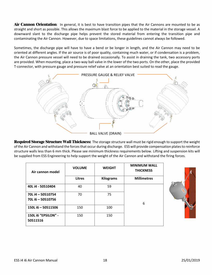
Air Cannon Orientation: In general, it is best to have transition pipes that the Air Cannons are mounted to be as straight and short as possible. This allows the maximum blast force to be applied to the material in the storage vessel. A downward slant to the discharge pipe helps prevent the stored material from entering the transition pipe and contaminating the Air Cannon. However, due to space limitations, these guidelines cannot always be followed.
Sometimes, the discharge pipe will have to have a bend or be longer in length, and the Air Cannon may need to be oriented at different angles. If the air source is of poor quality, containing much water, or if condensation is a problem, the Air Cannon pressure vessel will need to be drained occasionally. To assist in draining the tank, two accessory ports are provided. When mounting, place a two-way ball valve in the lower of the two ports. On the other, place the provided T-connector, with pressure gauge and pressure relief valve at an orientation best suited to read the gauge.
Required Storage Structure Wall Thickness: The storage structure wall must be rigid enough to support the weight of the Air Cannon and withstand the forces that occur during discharge. ESS will provide compensation plates to reinforce structure walls less than 6 mm thick. Please see minimum thickness requirements below. Lifting and suspension kits will be supplied from ESS Engineering to help support the weight of the Air Cannon and withstand the firing forces.
Air cannon model VOLUME WEIGHT
MINIMUM WALL
THICKNESS
Litres Kilograms Millimetres
40L i4 - 50510404 40 59
6
70L i4 – 50510754
70L i6 – 50510756
70 75
150L i6 – 50511506 150 100
150L i6 “EPSILON” -
50511516
150 150
PRESSURE GAUGE & RELIEF VALVE
BALL VALVE (DRAIN)

ESS i4 i6 Air Cannon Manual 19 25/01/2019
High Temperature Applications: In case of firing an air cannon into areas of ambient temperatures in excess of 1100°C, a drop-in Thermo Safety Shield (P/N: 51101204) needs to be affixed between the air cannon and the nozzle. This helps protect hot air and particles from coming in contact with the valve body. It is also a requirement to have at least 1.5 metres of transition pipe between the hot environment and the tank. These requirements will be handled by ESS.
Air Cannon Air Supply Components: As described under “Required Accessories” (pages 11-13) there are a number of air control components necessary for full operation. To ensure safe operation and optimum performance of your Air Cannon system, install these air control components as shown in the plumbing diagrams in Air Supply & Control - Component Installation: on page 23.
Visual Inspection: Please note the condition of the shipping container before opening. The shipping container will include the Air Cannon, pressure relief valve, operating instructions, identification information, and warranty card. Make sure all parts are located before discarding the container. Inspect the Air Cannon for any damage, such as dents, that might have occurred during shipment. Any Air Cannon accessories (valves, discharge assemblies, timers, etc.) ordered from ESS Engineering will be packaged separately. Please verify that all items ordered have been received. Contact ESS Engineering Customer Service or your distributor if there are any missing parts, apparent damage, or other irregularities.
Temporary Plug Removal: Tank openings are fitted with plastic plugs which are removed prior to attaching the air line, discharge pipe, or pressure relief valve. The small port at the end of the tank near the discharge opening has a steel plug. This is a permanent plug that should not be removed unless this port is needed for a drain valve or as an alternate location for the pressure relief valve.
Before working on any storage structure, lock out / tag out any equipment that loads or unloads material from
the structure.
If equipment will be installed in an enclosed area, test gas levels or dust content before using a cutting torch or welding equipment. Using a cutting torch or welding in an area with sufficient gas or dust levels can cause an explosion.

ESS i4 i6 Air Cannon Manual 20 25/01/2019
Installing Transition Pipes:
The discharge assembly must be able to support the Air Cannon and directs the air blast towards the problem area. Structure Wall Opening: Instructions for making the opening for the discharge pipe in the storage structure wall
are not specific because of the wide variety of structures, wall materials, etc. Generally, the hole in the wall for the discharge pipe will be circular if the pipe is entering perpendicular to the wall or an ellipses of sorts if mounting tangentially.
For high temperature applications the discharge pipe must be long enough to ensure the Air Cannon piston is
not exposed to temperatures exceeding 119°C. Exposure to temperatures greater than 119°C will cause the piston to seize. Damage caused by operating ESS Air Cannons at temperatures in excess of 119°C are not covered by the warranty.
Mounting to the Chute Wall:
Refer to Air Cannons – Installation Detail on page 47.
1. Orientate the placement of all tanks, transition pipes, and compensation plates with the provided installation drawings before starting.
2. Using the profile of the supplied compensation plate, make a template on cardboard or other durable material. Enlarge the elliptical shape of the pattern by 15mm (1/2”) for ease of fitting during installation.
3. Use the pattern to mark the opening on the structure wall. When working from the outside of the structure, the long diameter of the elliptical shape should run from upper left to lower right (unless you have ordered a special configuration).
4. Cut the hole in the structure wall. 5. Fit the discharge pipe into the wall so the mount plate is flush with the outer wall surface. Evaluate the amount of
pipe extending into the storage chamber. Cut the pipe using a square cut (perpendicular to the length of the pipe) so the lower edge is flush with the inside of the structure wall. The upper edge will protrude into the flow area slightly.
6. Be sure the discharge assembly is in place with the mount plate flush with the outer wall surface. Fasten with bolts or seal weld the mount plate to the wall, depending on requested design.
IMPORTANT

ESS i4 i6 Air Cannon Manual 21 25/01/2019
Mounting a Fanjet Nozzle:
Fanjet nozzles are designed to have excess material. Trim the excess material to be flush with the inside of the chute as necessary, and securely weld. Compensation plates will be provided if the chute wall is deemed too thin to support the weight of the air cannon system.
Mounting a 90 degree Fanjet:
The 90 degree fanjet nozzle is designed to blast air parallel to the chute wall in order to shear material away, while the transition pipe remains perpendicular to the wall. Ensure the chute wall cutout is large enough to allow the 90 degree bend to pass through, but not too large so as to be unable to weld securely, and that the discharge area of the nozzle is inside the chute.
CUT EXCESS TO BE FLUSH WITH INNER CHUTE FACE
ESS i4 i6 Air Cannon Manual 22 25/01/2019
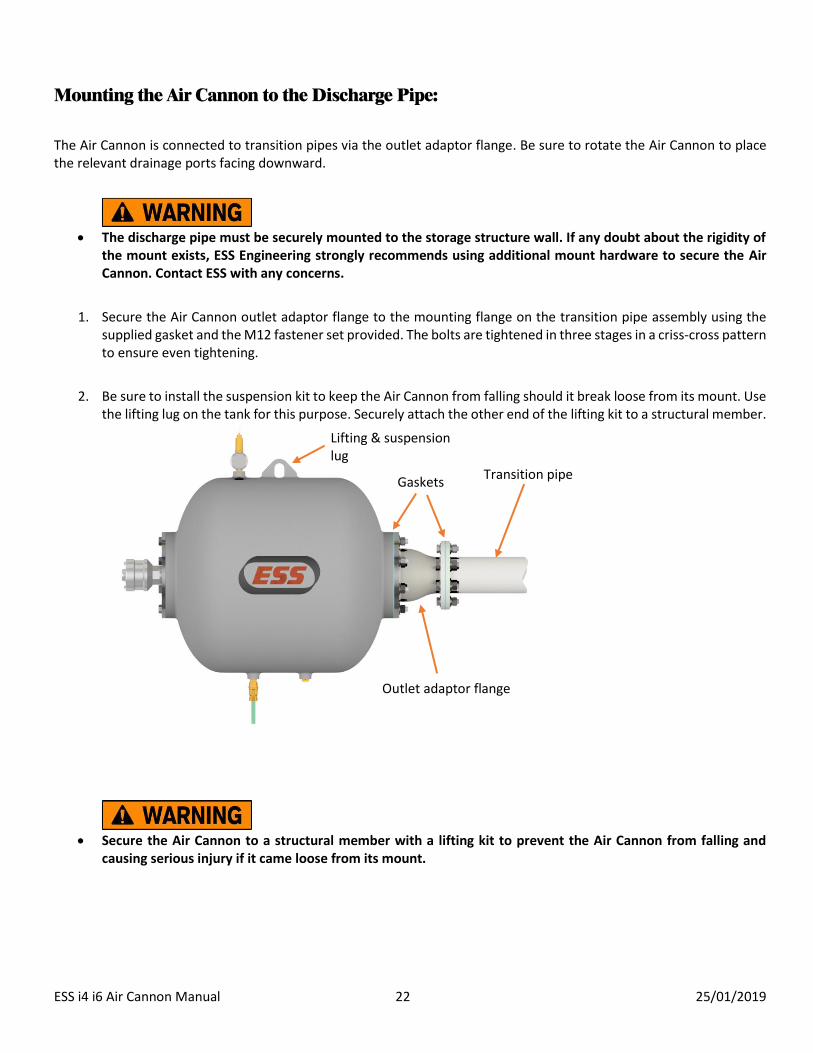
Mounting the Air Cannon to the Discharge Pipe:
The Air Cannon is connected to transition pipes via the outlet adaptor flange. Be sure to rotate the Air Cannon to place the relevant drainage ports facing downward.
The discharge pipe must be securely mounted to the storage structure wall. If any doubt about the rigidity of
the mount exists, ESS Engineering strongly recommends using additional mount hardware to secure the Air Cannon. Contact ESS with any concerns.
1. Secure the Air Cannon outlet adaptor flange to the mounting flange on the transition pipe assembly using the supplied gasket and the M12 fastener set provided. The bolts are tightened in three stages in a criss-cross pattern to ensure even tightening.
2. Be sure to install the suspension kit to keep the Air Cannon from falling should it break loose from its mount. Use the lifting lug on the tank for this purpose. Securely attach the other end of the lifting kit to a structural member.
Secure the Air Cannon to a structural member with a lifting kit to prevent the Air Cannon from falling and
causing serious injury if it came loose from its mount.
Transition pipe Gaskets
Outlet adaptor flange
Lifting & suspension lug

ESS i4 i6 Air Cannon Manual 23 25/01/2019
Attach one end of the provided lifting kit to a suitable structural member, and the d-shackle at the other end to the lifting lug on the air cannon. Ensure the lifting kit has no slack, but isn’t too taut as to attempt to support the tank. The lifting kit is there as a fail-safe if either the supporting pipework fails, or the tank needs to be removed from the pipework.
Be sure to apply PTFE thread tape to all threads before installing.
Air Supply & Control - Component Installation:
Air Cannon Component Installation – Air supply and control: Install each control component using PTFE tape or thread sealant on all threaded connections. Be sure to use suitable sealant for high temperature applications.
Be sure all connections are air tight. Any leak along the Air Cannon air supply line may cause the Air Cannon
to discharge unexpectedly causing injury.
Be sure the input signal/power is the correct voltage and type to operate the solenoid.
IMPORTANT

ESS i4 i6 Air Cannon Manual 24 25/01/2019
Option 1 - Arrangement:
Install the firing arrangement as shown below. It is recommended to use 12mm hose from the air supply to port 1 on
the firing solenoid, but this is only necessary for filling times. Use 6mm hose between the 6mm push fit on the tee
connector and port 1 on the control (smaller) solenoid, and also between port 2 of the control solenoid to the pilot port
on the firing solenoid. Mount the firing solenoid directly to the Quick Exhaust valve shown via the fitting in Port 2. The
firing arrangement can be test “fired” by depressing the white button on the smaller solenoid. Holding this down will
cause the air to begin flowing as if the tank was filling, and releasing the button will cause the air to exhaust/”fire”.
Without the control solenoid triggered, air should not be flowing.
Figure – MAC 100 & 55 Series, orange indicating air supply hose, with fittings clockwise starting left (at port 2):
Part Number Description Placement
02404540B Nipple, ¾” x 3/8” Reducer, Brass Port 2 (firing solenoid)
02370007B Elbow, 1/8M-6mm P/fit, Brass Pilot port (firing solenoid)
02366010 Connector, 1/8”M-6mm P/fit (2 off), Plastic Port 1 & 2 (control solenoid)
02650305 Silencer, 1/8”, Bantam Port 3 (control solenoid)
02392300P Reducer, 12mm-6mm P/fit, Plastic On part # 02378120P
02378120P Tee, 12mm P/fit, Plastic Connected to air supply, and port 1 of both
solenoids, via 12mm and 6mm hose.
02370265B Elbow, 3/8”M-12mm, Tube, P/fit, Brass Port 1 (firing solenoid)
02400250B Elbow, 3/8” M/F, Screwed, Brass Port 3 (firing solenoid)
02650315 Silencer, 3/8”, Bantam To the elbow on port 3 (firing solenoid)
Depressing this (such as with a pen) will manually trigger the valve. This can be used to test the valve without
electrical connection. Port 1
Port 2
Port 3
Port 3
Port 2
Port 1
Pilot
Air supply
Note
The distance between both solenoids is not crucial.
Control Solenoid
Slave Valve
6mm hose
12mm hose

ESS i4 i6 Air Cannon Manual 25 25/01/2019
Option 2 - Arrangement:
Be sure the MAC solenoid is set in the normally open position (‘3-NO’ is indicated on the small white tab visible from the top). Test that the solenoid indicator light turns red when triggered via the PLC. Also test that when air is connected to port 1, it flows out port 2, and when triggered air stops flowing from 1 to 2. This means it is now open 2 to 3, which when fully connected to the tank, the air in the supply line from port 2 to the tank will exhaust out of port 3. There is a white button for manual testing. This button should not be used for actual firing as it is much slower at switching the valve and will affect blast performance.
Figure – MAC 56 Series, orange indicating air supply hose, with fittings left to right:
Part Number Description
0236633B Connector, ½”M-12mm TUBE P-FIT
02404310B Nipple, ½” x 37mm long, hex, Brass
02820315B Valve, ½”, Non-Return (check), Brass
0236633B Connector, ½”M-12mm TUBE P-FIT
Depressing this (such as with a pen) will manually trigger the valve. This can be used to test the valve without electrical connection.
Port 1
Port 3
Port 2 Air supply To tank
Ensure arrow points in the direction of air flow
Indicator tab should display ”3-NO”

ESS i4 i6 Air Cannon Manual 26 25/01/2019
Be sure to test the solenoid valve before applying air pressure.
The solenoid valve may not operate if the inlet pressure is less than 2.75 bar (40 psi).
Quick Exhaust Valve Installation (Option 2): ESS Air Cannons come standard with a Global G-Series Quick Exhaust Valve mounted. To the plant air inlet “IN” port, connect a 12mm push fit connector to the air supply line from port 2 on the MAC solenoid. This is the only connection required from the solenoid to the air cannon.
Figure – Global QEV. Left side is tank, and the QEV is shown with relevant fittings:
Part Number Description
02392515B Bush, ¾”-1/2” Reducing BRASS
0236633B Connector, ½”M-12mm TUBE P-FIT
See Section 9 General Overview - How the Air
Cannon Works: on Page 9
MAC 56 Series w/ fittings (see page 25)
The Quick Exhaust Valve is fitted with two exhaust port bands. If “Replace Bands Now!” is visible, the outer
band is missing and should be replaced immediately.
IMPORTANT
IMPORTANT
Keep this distance as short as possible. Do not exceed 30 metres.

ESS i4 i6 Air Cannon Manual 27 25/01/2019
Air Supply - Overall Arrangement
Figure – showing the air supply arrangement for both Option 1 and Option 2.
Option 1 Arrangement Option 2 Arrangement
FRG
SIGNAL/POWER
FRG
CONTROL SOLENOID
AIR IN 12mm HOSE
CONTROL SOLENOID
FIRING SOLENOID
PILOT LINE 6mm HOSE
BALL VALVE BALL VALVE

ESS i4 i6 Air Cannon Manual 28 25/01/2019
SECTION IV - AIR CANNON START-UP
PROCEDURES
1. Make sure all connections for Air Cannons, discharge assemblies, and air & electrical components are secure. 2. Check all 3-Way Control Valves to ensure they are correctly set up (see page 24 & 25) 3. Set Filter-Regulator-Gauge (FRG) to minimum pressure position. 4. Open the Shut-off Ball Valve to allow plant air to enter the system. 5. Set the FRG to the pressure desired for charging the Air Cannons: Minimum pressure = 280 kPa (40 psi). Solenoid
valves might not operate consistently at lower pressures. Maximum pressure = 860 kPa (125 psi). The Air Cannon tank is rated for 1034 kPa (150 psi). Its safety relief valve will release and depressurize the tank if the pressure exceeds 965 kPa (140 psi). Pressure between 550 and 860 kPa (80 and 125 psi) will give excellent performance for most applications.
Wear hearing protection. If there are sufficiently large leaks it may cause the air cannon to unexpectedly discharge.
6. Check all airline pipe connections for leaks. Mark all leaks found and de-pressurize the system by closing the Shut-off Ball Valve.
7. Repair any leaks found in Step 6 and return to Step 3. If no leaks were found, continue with Step 8. 8. Test each Air Cannon separately via the firing arrangements. MAC valves can be manually fired by depressing a
plastic piece on the solenoid body (see the Figures on Page 24 and 25) 9. If the Air Cannon System is to be controlled by a micro-controller based sequencing timer, such ESS’ 8 Blaster
Sequence Controller, ensure it is connected as per the instructions. Firing times will be specified by ESS based on a case by case basis.
10. After satisfactory completion of the above Steps, your ESS Engineering Air Cannon system is ready for use.
Contact ESS with any questions or concerns about the installed equipment. See APPENDIX A - TROUBLESHOOTING on page 38 if any problems arise.

ESS i4 i6 Air Cannon Manual 29 25/01/2019
SECTION V - MAINTENANCE
Preventive maintenance is important to ensure effective and safe performance of the Air Cannon system.
Lubrication: ESS Air Cannons require no lubrication.
Air Control Accessories: Check periodically to make sure all valves are clean and functional. The reservoir on the Filter-Regulator-Gauge should be drained daily. Clean unit and filter with warm water and mild soap as needed. Blow with compressed air to dry. Use a 40 micron filter when the filter element needs replacing.
Quick Exhaust Valve: Replace the exhaust port bands every 50,000 blasts or once per year. There should always be two bands in place. If “Replace Bands Now!” is visible, the outer band is missing and should be replaced immediately (see instructions SECTION VI - DIS/ASSEMBLY OF THE AIR CANNON, on page 30).
Air Cannon Mounting: All mounts must remain rigid. Check periodically and retighten as necessary. Any damaged or rusted parts should be repaired or replaced.
Air Cannon Internal Valve: The Air Cannon valve is designed to provide many years of maintenance free operation. Should the Air Cannon malfunction or performance appear to decrease, the internal valve should be inspected for wear or contamination. If the Air Cannon is used in a harsh environment, several Air Cannons in the system should be inspected periodically - semi-annually or annually - during routine plant maintenance periods. This rotating inspection schedule should indicate if the Air Cannons are showing any signs of wear or contamination that will need attention. Follow the instructions in Section VI - Disassembly and Assembly of the Air Cannon.
Spare Parts Recommendations: See APPENDIX C – Recommended Spares on page 50. If the Air Cannon is not used in a harsh environment, an inventory of spare parts may not be needed.
Pressure Vessel Inspection: operators must comply with the relevant Mines Safety Regulation, AS 3788 – Pressure Vessels - In-Service Inspection, or their own Risk Based Inspection (RBI) procedures. If the Air Cannon tank has reached its cyclic design life (see table below) or is found to be damaged in any way, it should be replaced immediately.
Tank Size (L) Design Life (cycles)
40 3,500,000
70 3,500,000
150 3,200,000
Epsilon 150 15,000,000
250 3,200,000
IMPORTANT
ESS i4 i6 Air Cannon Manual 30 25/01/2019
SECTION VI - DIS/ASSEMBLY OF THE AIR
CANNON
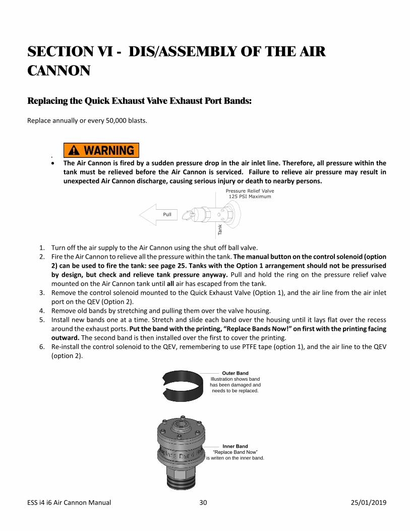
Replacing the Quick Exhaust Valve Exhaust Port Bands: Replace annually or every 50,000 blasts.
The Air Cannon is fired by a sudden pressure drop in the air inlet line. Therefore, all pressure within the tank must be relieved before the Air Cannon is serviced. Failure to relieve air pressure may result in unexpected Air Cannon discharge, causing serious injury or death to nearby persons.
1. Turn off the air supply to the Air Cannon using the shut off ball valve. 2. Fire the Air Cannon to relieve all the pressure within the tank. The manual button on the control solenoid (option
2) can be used to fire the tank: see page 25. Tanks with the Option 1 arrangement should not be pressurised by design, but check and relieve tank pressure anyway. Pull and hold the ring on the pressure relief valve mounted on the Air Cannon tank until all air has escaped from the tank.
3. Remove the control solenoid mounted to the Quick Exhaust Valve (Option 1), and the air line from the air inlet port on the QEV (Option 2).
4. Remove old bands by stretching and pulling them over the valve housing. 5. Install new bands one at a time. Stretch and slide each band over the housing until it lays flat over the recess
around the exhaust ports. Put the band with the printing, “Replace Bands Now!” on first with the printing facing outward. The second band is then installed over the first to cover the printing.
6. Re-install the control solenoid to the QEV, remembering to use PTFE tape (option 1), and the air line to the QEV (option 2).
Pull
Pressure Relief Valve125 PSI Maximum
Tank
Outer Band
Illustration shows band
has been damaged and
needs to be replaced.
Inner Band
“Replace Band Now”
is writen on the inner band.

ESS i4 i6 Air Cannon Manual 31 25/01/2019
Dismounting the Air Cannon:
Tools Required: Two (2) each 24mm spanner or shifter 500 lb (230 kg) capacity hoist
The Air Cannon is fired by a sudden pressure drop in the air inlet line, therefore, all pressure within the tank must be relieved before the tank can be dismounted. Failure to relieve air pressure may result in unexpected Air Cannon discharge, causing serious injury or death to nearby persons.
1. Turn off the air supply to the Air Cannon using the shut off ball valve. 2. Fire the Air Cannon to relieve all the pressure within the tank. If it is not possible to fire the Air
Cannon, pull the ring on the pressure relief valve mounted on the Air Cannon tank. 3. Remove the pressure relief valve from the Air Cannon. 4. Disconnect the air line from the Quick Exhaust Valve air inlet port. 5. Loosen the mounting bolts connecting the Air Cannon coupling to the discharge pipe. Be sure not
to loosen the bolts connecting the coupling to the Air Cannon tank. 6. Using the hoist, support the Air Cannon by the ring on the end of the tank. Remove the safety cable. 7. Remove the mounting bolts previously loosened and lift the Air Cannon clear of the discharge pipe.
If the gasket is damaged, discard it and use a new gasket of the same type when remounting the Air Cannon. If the gasket is in good condition, it can be reused when remounting the Air Cannon.
8. Lower the Air Cannon to the ground and transport it to an appropriate working area.
Pull
Pressure Relief Valve125 PSI Maximum
Tank
Secure tank to suitable lifting apparatus, and take up slack
Once secured and lifted, undo fasteners attaching the tank and outlet adaptor flange to the transition pipe.
At this stage, do not remove fasteners attaching the outlet adaptor to tank.

ESS i4 i6 Air Cannon Manual 32 25/01/2019
Removing the Internal Valve:
Tools Required: Two (2) each 24mm spanner or shifter 24” Pipe Wrench Large Shifter (>24mm) Refer to APPENDIX B – Assembly Drawings on page 39 for the full parts list and relevant assembly views.
1. The Quick Exhaust Valve does not have to be removed to access the internal valve.
The internal fill line/pipe does not have to be removed to access the internal valve. If no problems are suspected with the internal fill pipe, skip step #2 and proceed to #3.
2. Use the shifter to loosen the Quick Exhaust Valve. Remove the valve and the connected internal fill line from the tank as a single unit.
It should not be necessary to remove the internal fill pipe from the QEV. The length of the fill pipe from the QEV is important to not block fill ports on the piston end.
Note
IMPORTANT
Air line fill pipe
Outlet Adaptor Flange
Quick Exhaust Valve

ESS i4 i6 Air Cannon Manual 33 25/01/2019
Check the end of the fill pipe for damage or burns. Check the fill line for cracks or other damage.
3. Remove the bolts that fasten the outlet adaptor to the tank flange. Remove the adaptor and the gasket from the Air Cannon. If the gasket is damaged, discard it and use a new gasket of the same type when assembling the Air Cannon. If the gasket is in good condition, it can be reused.
4. Push the valve piston back and insert fingers into the valve body ‘windows’. Carefully pull the valve body and flange seat from the tank, taking note of the two o-rings sealing the valve body to the flange seat, and the flange seat to the tank.
5. Inspect the inside of the Air Cannon tank for corrosion and contamination. Clean the inside of the tank with compressed air prior to reassembly.
Once the outlet adaptor flange is removed the valve is no longer secured, and can fall out.
It is not necessary to remove anything from this end to access the internal valve.

ESS i4 i6 Air Cannon Manual 34 25/01/2019
Valve Disassembly:
Tools Required: Arbor Press (a soft wooden block and hammer may be used in place of the arbor press) Large Internal Circlip Pliers Small Flat Blade Screw Driver
1. Use the large retaining ring pliers to remove the retaining ring at the base of the valve cap.
The retaining ring is under high tension. Use care to ensure the ring does not fly off the pliers or out of the valve body and injure nearby persons.
2. Inspect the retaining ring and retaining ring groove for wear or damage. Replace the retaining ring or valve body if damage is evident.
3. Carefully remove the piston, and valve cap from the valve body. Light pressure on the face of the piston may be necessary.
4. After the piston and valve cap are removed, press the valve seat from the valve body. 5. Use the flat blade screw driver to carefully pry the O-rings from the valve seat, piston and valve cap.
Valve Inspection:
1. Clean all valve parts thoroughly in a non-solvent based cleaner. 2. Inspect the valve body bore for deep scratches, pits, grooves, or corrosion. The valve body bore must be in good
condition to function properly. 3. Inspect the sealing face of the valve seat for smoothness. The valve seat must be smooth to properly seat the
piston. 4. Check the piston face, sealing bevel, and O-rings for heat damage, chemical erosion, or signs of wear. The piston
must be in good condition with smooth sealing and wear surfaces. Minor pitting in the nose of the piston is acceptable if the pits are less than 1/16” (2 mm) deep and the sealing bevel is not pitted. Any distortion of the piston, which hampers smooth sliding or exhibits excessive clearance in the valve body, is unacceptable.
5. It is recommended that, once removed, all O-rings on the piston, valve seat, and valve cap be replaced. Contact ESS for a replacement kit if necessary.

ESS i4 i6 Air Cannon Manual 35 25/01/2019
Assembling the Valve:
1. Replace the O-ring on the valve seat, valve cap, and piston. The piston uses a “floating” type O-ring fit, therefore the piston O-ring will not fit tightly in its groove. Sparingly coat all O-rings, except the O-ring on the cap that serves as the check valve, with silicone lubricant/grease. Be careful not to damage the O-rings.
2. Assembly of the Air Cannon valve proceeds in the reverse order of disassembly except all parts are individually pressed into the valve body. Do not press all parts in at the same time. Using the press, position the valve seat (bevel side up) completely down into the valve body. The bevelled side of the seat should match the bevelled face of the piston. Take care that the O-ring is not cut as it passes over the window openings in the valve body.
3. Lightly oil the sides of the piston and the bore (internal surface of the valve body). Align the O-ring in the groove
on the side of the piston.
4. Making sure the piston remains straight, push the piston (bevel face down) and O-ring into the valve body until
Beveled
Side

ESS i4 i6 Air Cannon Manual 36 25/01/2019
the O-ring approaches the valve cap seat (shoulder machined inside valve body at top of piston bore).
5. Due to the floating O-ring fit, the O-ring may bind as it tries to pass over the valve cap seat, preventing the
piston from sliding smoothly into the bore. While using only hand pressure on the piston, use a thin piece of metal
or screw driver to work the O-ring into the piston groove, allowing the piston to slide completely into the bore.
6. Press the valve cap into the valve body until it reaches the valve cap seat. The retaining ring groove will be visible
above the cap.
7. Install the retaining ring using the retaining ring pliers. The retaining ring will have a sharp edge and a rounded edge.
Check the sharp edge of the retaining ring for burrs or rounded areas. Install the retaining ring with the sharp edge
away from the valve cap. Check that the retaining ring is properly seated in the valve body groove.
8. Check the piston to make sure it slides easily within the valve body.
9. Check the O-ring check valve on the valve cap to see that it is properly seated in its groove.

ESS i4 i6 Air Cannon Manual 37 25/01/2019
Assembling the Air Cannon:
1. If the internal fill line/pipe and QEV unit was removed, check to see that the end is smooth, burr free, and slightly bevelled, so it will slide easily into the seal in the valve cap inlet port. Install the internal fill line into the tank. If the fill pipe was not removed, it can still be inspected via the valve body side. Be sure to use PTFE tape on the Quick Exhaust Valve threads.
2. Examine the end of the internal fill line from the tank exhaust opening. The fill line must be centred within the tank opening. If it is not centred, using a rod slipped into the end of the fill line for leverage, bend the tube so it appears centred.
3. Apply a small amount of silicone grease to the end of the fill line prior to installing the valve body.
4. If the flange seat o-rings were removed, lightly coat in silicone grease and reinstall the o-rings into the flange seat.
5. Reseat the flange seat in the exhaust opening of the tank, ensuring that the small inner lip is facing outwards from the tank.
6. Reinstall the valve assembly on the flange seat in the tank opening, taking care to slide the inlet port on the valve cap over the end of the fill line. When contact is made between the fill line and the O-ring seal in the cap inlet port, twist and slightly rock the valve until the valve slips fully into the recess in the tank flange.
7. Inspect and install the flange coupling. Be sure to use a new gasket, if necessary, between the Air Cannon tank flange and the coupling flange. The gasket should meet manufacturer’s specifications. No adhesive is required.

ESS i4 i6 Air Cannon Manual 38 25/01/2019
APPENDIX A - TROUBLESHOOTING
Prior to shipment, all ESS Air Cannons are tested for pressure and function according to corresponding pressure vessel regulations and quality manufacturing specifications. Despite the simple and sturdy construction, malfunctions can occur due to the kind of application, installation, and/or operation. The following list should help identify the causes of some problems that occur and gives possible solutions to eliminate those problems. Control Valve = 3-Way Solenoid Valve Arrangement (Option 1 and 2) (solenoid with electrical connection). Operating Valve = Quick Exhaust Valve. ISSUE - Air cannon wont fire or the blast is weak
- No air to/in tank
o Check all air line components
Ball valves in the supply line are open
Non-return valve is orientated correctly
o Check solenoids are correctly configured
Option 1 – both solenoids are set as normally closed. Triggering the control
solenoid causes air to flow via the pilot line to the firing solenoid, which opens
the pathway to the tank.
Option 2 – check that the control solenoid is set to “normally open” on the
indicator tab. Triggering the solenoid causes air to stop flowing through from
ports 1-2, and instead opens 2-3.
o Check air line fill pipe is not covering the internal valve’s fill ports due to incorrect length
or tightened wrongly.
- Low air pressure. If after firing the tank makes a low humming/vibrating noise it is indicative of
low air pressure.
o Check tank pressure before firing
o Check that the regulator is set at the correct pressure
o Check for leaks
o Option 1 – check the actuating signal to the control solenoid is long enough to fill the
tank to the desired pressure.
- Control solenoid not triggering
o Check plug wiring is correct
o Check voltage and type requirements
- Control solenoid is triggering but not firing the tank
o Option 1 – ensure the actuating signal is allowing air to sufficiently fill the tank. With
sufficient air, and when the signal stops, the tank will fire.
o Option 2 - Check the indicator tab is set on “3-NO”.
o Option 2 – the firing solenoid is too far away from the tank
- Piston is not reseating
o Clean or replace piston and/or O-rings.
o Check the valve seat and valve walls for damage

ESS i4 i6 Air Cannon Manual 39 25/01/2019
APPENDIX B – Assembly Drawings
40L i4 – Exploded Drawing
ESS i4 i6 Air Cannon Manual 40 25/01/2019
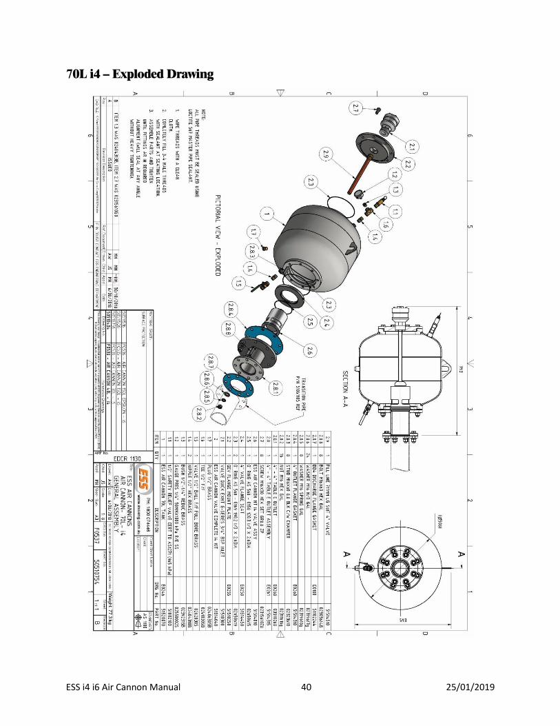
70L i4 – Exploded Drawing

ESS i4 i6 Air Cannon Manual 41 25/01/2019
70L i6 – Exploded Drawing

ESS i4 i6 Air Cannon Manual 42 25/01/2019
150L i6 – Exploded Drawing

ESS i4 i6 Air Cannon Manual 43 25/01/2019
150L i6 “Epsilon” – Exploded Drawing

ESS i4 i6 Air Cannon Manual 44 25/01/2019
I4 Internal Valve – Exploded Drawing

ESS i4 i6 Air Cannon Manual 45 25/01/2019
I6 Internal Valve – Exploded Drawing

ESS i4 i6 Air Cannon Manual 46 25/01/2019
Quick Exhaust Valve – Exploded Drawing

ESS i4 i6 Air Cannon Manual 47 25/01/2019
Air Cannons – Installation Detail

ESS i4 i6 Air Cannon Manual 48 25/01/2019
Option 1 Arrangement – Normally Closed

ESS i4 i6 Air Cannon Manual 49 25/01/2019
Option 2 Arrangement – Normally Open

ESS i4 i6 Air Cannon Manual 50 25/01/2019
APPENDIX C – Recommended Spares
Flange Seat O-ring Kit
Refer APPENDIX B – Assembly Drawings on page 39 onwards
Valve size Item Number Description Part Number Quantity
I4 2.3 O-ring AS 568 – 0169 190.2 I/D x 2.6DIA 02650619 1
2.5 O-ring AS 568 – 0158 120.3 I/D x 2.6DIA 02650615 1
I6 2.5 O-ring AS 568 – 0169 190.2 I/D x 2.6DIA 02650619 1
2.9 O-ring AS 568 – 0168 183.8 I/D x 2.6DIA 02650617 1
Internal Valve Kit
Refer to I4 Internal Valve – Exploded Drawing on page 44 and I6 Internal Valve – Exploded Drawing on page 45
Valve Size Item Number Description Part Number Quantity
I4
2 O' RING VITON AS 568 - 0240 02650623 1
4 O' RING VITON AS 568 - 0237 02650622 1
6 O' RING VITON AS 568 - 0343 02650626 2
7 O' RING VITON AS 568 - 0208 02650620 1
9 O' RING VITON AS 568 - 0331 02650625 1
10 O' RING VITON AS 568 - 0118 02650611 1
11 Retaining Ring 5000-400 02308960 1
I6
2 O' RING VITON AS 568 - 0431 02650627 2
4 O' RING VITON AS 568 - 0254 02650624 1
6 O' RING VITON AS 568 - 0436 02650628 1
7 O' RING VITON AS 568 - 0212 02650621 1
9 O' RING VITON AS 568 - 0343 02650626 1
10 O' RING VITON AS 568 - 0122 02650612 1
11 Retaining Ring 5000-625 02308965 1

ESS i4 i6 Air Cannon Manual 51 25/01/2019
Gasket Kit
Refer to APPENDIX B – Assembly Drawings on page 39
Size Item Number Description Part Number Quantity
I4 2.8.4 4” Outlet flange gasket 51514310 1
2.8.7 BB4 Discharge flange gasket 51102244 1
I6 2.7.4 6” Outlet flange gasket 51506310 1
2.7.9 BB4 Discharge flange gasket 51102244 1
Quick Exhaust Valve Kit
Refer to Quick Exhaust Valve – Exploded Drawing on page 46
Item Number Description Part Number Quantity
1 Screw HSHC ¼-20UNC-3/4” 6
3 O’ RING BUNA 568 – 0039 (QEV O’ RING KIT)
02650598 1 4 O’ RING BUNA 568 – 0331 (QEV O’ RING KIT)
7 O’ RING BUNA 568 – 0219 (QEV O’ RING KIT)
8 Exhaust band – Outer (QEV EXHAUST BAND KIT) 02650690
1 9
Exhaust band – “Replace now” (QEV EXHAUST BAND KIT)

Revision L 52 18/05/2018
APPENDIX D – Air Cannon Data Sheet

ESS Air Cannon i4 / i6 Operation Manual
SECTION 7- FINAL CHECKLIST
Site: ____________________________ Number: _____________________ Date: __________________ Site Equipment No./Location: _________________________ Site Contact: _________________________
Completed By: ______________________________________ (Circle Yes or No Below)
1. Was equipment to ESS Specification? _________________________________ Yes/No
Drawing No. Ref: __________________________________________ Attached? Yes/No If No, WHY _______________________________________________________________________________ ________________________________________________________________________________________ Will this affect performance? Yes/No If Yes, WHY ______________________________________________________________________________ ________________________________________________________________________________________
2. Was this a standard service inspection installation? Yes/No If No, WHY _______________________________________________________________________________ ________________________________________________________________________________________ ________________________________________________________________________________________
3. Was work carried out as per procedure and JSA? Yes/No If No, WHY _______________________________________________________________________________ ________________________________________________________________________________________
4. Is equipment fit for commissioning? Yes/No If No, WHY _______________________________________________________________________________ ________________________________________________________________________________________
5. Was a final inspection carried out while plant was running? Yes/No If No, WHY _______________________________________________________________________________
________________________________________________________________________________________
6. Has anything changed from previous service / inspection / installation? Yes/No If Yes, WHAT _____________________________________________________________________________ ________________________________________________________________________________________

ESS Air Cannon i4 / i6 Operation Manual
7. Is equipment performance to Client expectations? Yes/No If No, WHY _______________________________________________________________________________ ________________________________________________________________________________________
ESS Signature:

ESS Air Cannon i4 / i6 Operation Manual
MANUAL VERSION 1.1.5