“establishing e-training environment for training...
TRANSCRIPT
“Establishing e-Training Environment for Training Technical Teachers and Students” (Creation of 4 Courses)
Course code: 15341 Course Title : Data Communication & Networks
Target Audience: Students of Diploma in Computer Science & Engineering and Information Technology in general and Diploma in Computer Networks in particular.
(84 Hrs)
Course Objectives:
1.0 To understand the concept of data communication and modulation techniques.
2.0 To comprehend the use of different types of transmission media and network devices.
3.0 To understand the error detection and correction in transmission of data.
4.0 To understand the concept of flow control, error control and LAN protocols.
5.0 To understand the functions performed by Network Management System.
The courseware is designed to provide detailed information for learning the content. The content as prescribed in the curriculum is structured as below.
• Course Objectives
• Course Plan
• Content Outline
• Unit Objectives
• Modules
• Teaching Points
In general, a set of Teaching Points constitute a lesson. Sometimes, even single Teaching Point may be considered as a lesson. The content treatment is given keeping in view the abilities to be developed in the students of diploma programmes as specified in the objectives.
The content is presented with a combination of various multimedia elements (Text, Graphics, Animation, Audio & Video). The navigational features provided enable the learners to browse through the content seamlessly. Self-tests are embedded at appropriate instants after content coverage with respect to one or a set of objectives. With this, the learner would be able to make a self assessment of their learning. Based on this, they would be able to revisit the content if required.
The course is introduced by an Expert through a video based lecture demonstration. In addition to the above, audience is taken through a guided tour of how to use the courseware through a video preparation.
Resource Persons: • Dr. G. Kulanthaivel - SME • Dr. V P. Sivhakumaar - ID • Shri. A.P. Felix Arokiya Raj - ID

Data Communication and Networks
Course Plan:
Course Introduction
UNIT I Introduction, Modulation Techniques 16 Hours
UNIT II Transmission Media, Network Devices 16 Hours
UNIT III Error Detection and Correction 16 Hours
UNIT IV Flow and Error Control, LAN Protocols 18 Hours
UNIT V LAN Management 18 Hours
Course Summary
FAQ
Course Document
References
Credits
UNIT TITLE TIME (Hours)
I Introduction, Modulation Techniques 16
II Transmission Media, Network Devices 16
III Error Detection and Correction 16
IV Flow and Error Control, LAN Protocols 18
V LAN Management 18
Revision, Test 12
TOTAL 84 + 12 = 96

Unit – I Introduction & Modulation Techniques
Module – 1 Introduction to Data Communication
T1 Components of communication systems T2 Data representation T3 Data flow
Module – 2 Networks & Topologies
T1 Network criteria T2 Types of Networks (LAN) T3 Types of Networks (MAN) T4 Types of Networks (WAN) T5 Types of Network Connections T6 Types of Physical Topologies (Bus) T7 Types of Physical Topologies (Star) T8 Types of Physical Topologies (Ring) T9 Types of Physical Topologies (Mesh) T10 Types of Physical Topologies (Hybrid) T11 Network Models (peer to peer) T12 Network Models (Client server) T13 Network protocols and standards
Module – 3 OSI Model & TCP / IP Protocols
T1 Layered Task T2 Organization of the OSI Layers T3 Physical Layer T4 DataLink Layer T5 Network Layer T6 Transport Layer T7 Session Layer T8 Presentation Layer T9 Application Layer T10 Summary of Layers T11 TCP / IP Protocol Suite
Module No.
Name of the Module
1. Introduction to Data Communication
2. Networks & Topologies
3. OSI Model & TCP / IP Protocols
4. Analog & Digital Signals
5. Modulation Techniques
T1, T2,…….Tn – Teaching Points

Module – 4 Analog & Digital Signals
T1 Analog & Digital Signals T2 Sine Wave T3 Amplitude T4 Phase T5 Period and Frequency T6 Wavelength T7 Time and Frequency Domains T8 Composite Signals T9 Decomposition of a Composite periodic Signal T10 Time & Frequency Domains of a non-periodic Signal T11 Bandwidth T12 Digital Signal Terminologies T13 Transmission Impairment T14 Throughput T15 Latency (Delay) T16 Bandwidth - Delay Product T17 Jitter
Module – 5 Modulation Techniques
T1 Analog – to – Analog Conversion T2 Amplitude Modulation T3 Frequency Modulation T4 Phase Modulation T5 Analog – to – Digital Conversion T6 Pulse Code Modulation (PCM) Components T7 Sampling methods for PCM T8 Delta Modulation T9 Delta Modulation Components
T1, T2,…….Tn – Teaching Points
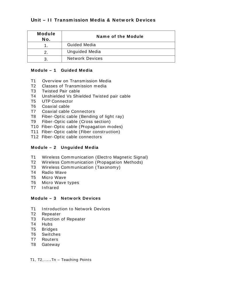
Unit – II Transmission Media & Network Devices
Module
No. Name of the Module
1. Guided Media
2. Unguided Media
3. Network Devices
Module – 1 Guided Media T1 Overview on Transmission Media T2 Classes of Transmission media T3 Twisted Pair cable T4 Unshielded Vs Shielded Twisted pair cable T5 UTP Connector T6 Coaxial cable T7 Coaxial cable Connectors T8 Fiber-Optic cable (Bending of light ray) T9 Fiber-Optic cable (Cross section) T10 Fiber-Optic cable (Propagation modes) T11 Fiber-Optic cable (Fiber construction) T12 Fiber-Optic cable connectors Module – 2 Unguided Media T1 Wireless Communication (Electro Magnetic Signal) T2 Wireless Communication (Propagation Methods) T3 Wireless Communication (Taxonomy) T4 Radio Wave T5 Micro Wave T6 Micro Wave types T7 Infrared Module – 3 Network Devices T1 Introduction to Network Devices T2 Repeater T3 Function of Repeater T4 Hubs T5 Bridges T6 Switches T7 Routers T8 Gateway
T1, T2,…….Tn – Teaching Points
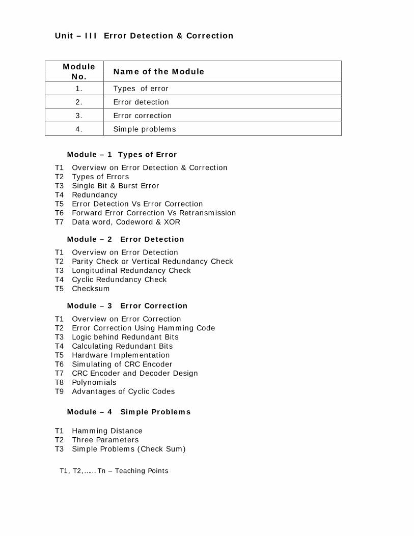
Unit – III Error Detection & Correction
Module – 1 Types of Error
T1 Overview on Error Detection & Correction T2 Types of Errors T3 Single Bit & Burst Error T4 Redundancy T5 Error Detection Vs Error Correction T6 Forward Error Correction Vs Retransmission T7 Data word, Codeword & XOR
Module – 2 Error Detection
T1 Overview on Error Detection T2 Parity Check or Vertical Redundancy Check T3 Longitudinal Redundancy Check T4 Cyclic Redundancy Check T5 Checksum
Module – 3 Error Correction
T1 Overview on Error Correction T2 Error Correction Using Hamming Code T3 Logic behind Redundant Bits T4 Calculating Redundant Bits T5 Hardware Implementation T6 Simulating of CRC Encoder T7 CRC Encoder and Decoder Design T8 Polynomials T9 Advantages of Cyclic Codes
Module – 4 Simple Problems
T1 Hamming Distance T2 Three Parameters T3 Simple Problems (Check Sum)
Module No.
Name of the Module
1. Types of error
2. Error detection
3. Error correction
4. Simple problems
T1, T2,…….Tn – Teaching Points

Unit – IV Flow and Error Control & LAN Protocols
Module – 1 Concept of Framing
T1 Data link control T2 Introduction to Framing T3 Character oriented protocols T4 Cop (Byte stuffing & Unstuffing) T5 Bit oriented protocols T6 Bop (Bit stuffing & Unstuffing) T7 Flow and Error Control Module – 2 Protocols
T1 Protocols T2 Simplest protocol (Design) T3 Simplest protocol (Flow Diagram) T4 Stop and wait protocol (Design) T5 Stop and wait protocol (Flow Diagram) T6 Significance of ARQ T7 Stop and wait ARQ (Design) T8 Stop and Wait ARQ (Flow Diagram) T9 Go-back-N ARQ (Send window) T10 Go-back-N ARQ (Receive window) T11 Go-back-N ARQ (Design) T12 Go-back-N ARQ (window size) T13 Selective reject automatic repeat request Module – 3 LAN Protocols
T1 Introduction to multiple accesses T2 Carrier sense multiple access T3 Carrier sense multiple access with collision detection T4 Carrier sense multiple access with collision avoidance T5 Token Passing
Module No.
Name of the Module
1. Concept of Framing
2. Protocols
3. LAN Protocols
4. Ethernet
T1, T2,…….Tn – Teaching Points

Module – 4 Ethernet
T1 Properties T2 Fast Ethernet (Introduction) T3 Fast Ethernet (Topologies) T4 Fast Ethernet (Implementation) T5 Fast Ethernet (Encoding) T6 Gigabit Ethernet (Introduction) T7 Gigabit Ethernet (Topologies) T8 Gigabit Ethernet (Implementation) T9 Gigabit Ethernet (Encoding)
T1, T2,…….Tn – Teaching Points
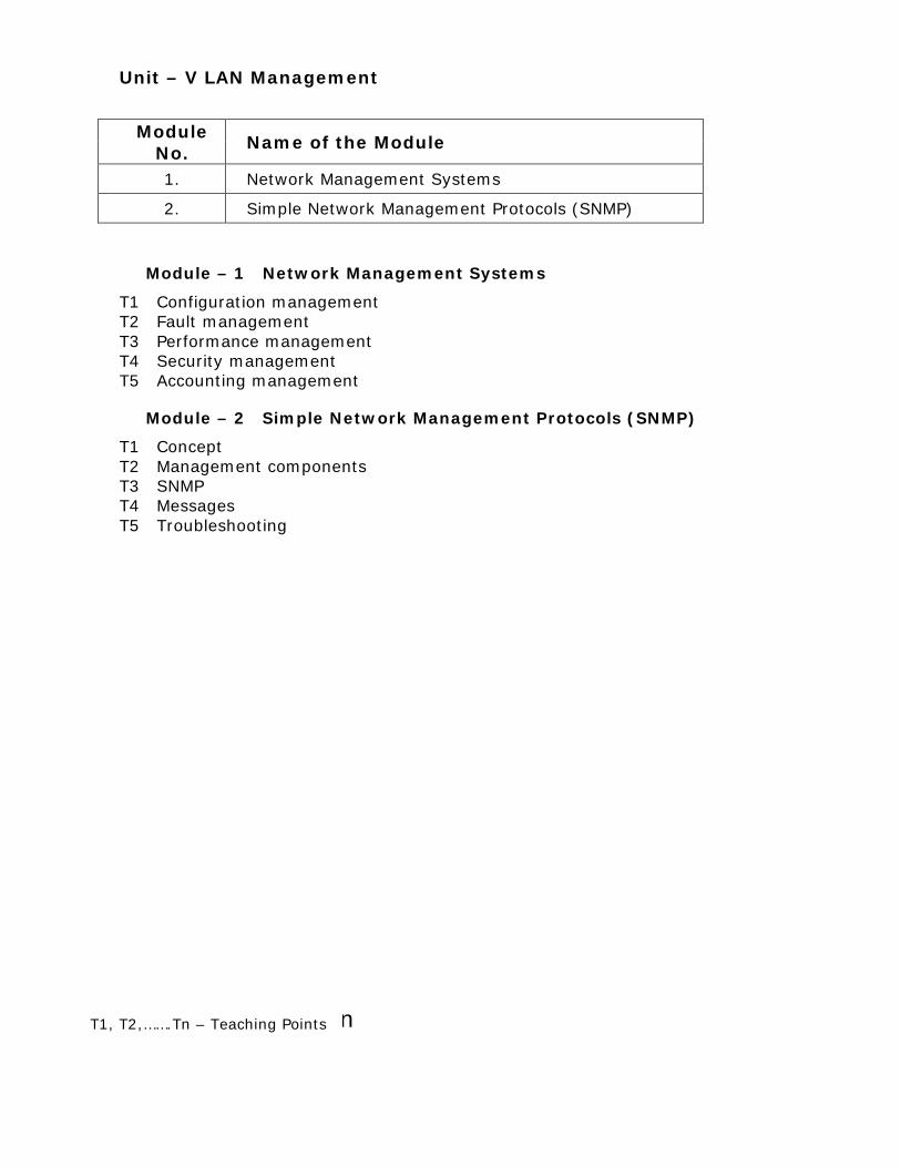
Unit – V LAN Management
Module – 1 Network Management Systems
T1 Configuration management T2 Fault management T3 Performance management T4 Security management T5 Accounting management
Module – 2 Simple Network Management Protocols (SNMP)
T1 Concept T2 Management components T3 SNMP T4 Messages T5 Troubleshooting
Course Introduction
Module No.
Name of the Module
1. Network Management Systems
2. Simple Network Management Protocols (SNMP)
T1, T2,…….Tn – Teaching Points

Course Introduction

1 – Introduction & Modulation Techniques 1.1 - Introduction to Data Communication 1.1.1 - Components of communication systems Data communication is the transfer of data from one device to another via some form of transmission medium. A data communications system has five components, namely, Data, Sender, Receiver, Transmission medium, and Protocol. The data is the information to be communicated. Popular forms of information include text, numbers, pictures, audio, and video. The Sender is the device that sends the data message. It can be a computer, workstation, telephone handset, video camera, and so on. The Receiver is the device that receives the data. It can be a computer, workstation, telephone handset, television, and so on. The transmission medium is the physical path by which a data message travels from Sender to Receiver. Some examples of transmission media include twisted-pair wire, coaxial cable, fiber-optic cable, and radio waves.

A Protocol is a set of rules that govern data communications. It represents an agreement between the communicating devices. Without a protocol, two devices may be connected but not communicating, just as a person speaking French cannot be understood by a person who speaks only Japanese. 1.1.2 –Data representation Information today comes in different forms such as text, numbers, images, audio and video. In data communications, text is represented as a bit pattern. A code such as ASCII is used to represent Text. The Text is converted into a sequence of zero’s and one’s. Numbers are also represented by bit patterns. However, a code such as ASCII is not used to represent numbers. The number is directly converted to a binary number to simplify mathematical operations. Images are also represented by bit patterns. An image is composed of a matrix of pixels, and each pixel is assigned a bit pattern. The size and the value of the pattern depend on the image. Audio is by nature different from text, numbers, or images. It is continuous, not discrete. Video can either be produced as a continuous entity (like a TV camera), or it can be a combination of images, each a discrete entity, arranged to convey the idea of motion. Analog video can be changed to digital video. 1.1.3 - Components of communication systems
Communication between two devices can be simplex, half-duplex, or full-duplex. In Simplex mode, the communication is unidirectional, as on a one-way street. Only one of the two devices on a link can transmit; the other can only receive. Keyboards, traditional monitors and printers are examples of simplex devices. The simplex mode can use the entire capacity of the channel to send data in one direction. In half-duplex mode, each station can both transmit and receive, but not at the same time. When one device is sending, the other can only receive, and vice versa. Walkie-talkies are half-duplex systems. The half-duplex mode is used in cases where there is no need for communication in both directions at the same time. The entire capacity of the channel can be utilized for each direction. In full-duplex mode both stations can transmit and receive simultaneously. The transmission medium sharing can occur in two ways, namely, either the link must contain two physically separate transmission paths or the capacity of the channel is divided between signals traveling in both directions. One common example of full-duplex communication is the telephone network. When two people are communicating by a telephone line, both can talk and listen at the same time.

1.1.4 Self Test
1. The fundamental basis of data communication is signal ________.
(Answer: propagation)
2. In half-duplex communication,
A. only one party can transmit data b. both parties can transmit but not at the same time c. both parties can transmit at the same time d. no party can transmit
(Answer: both parties can transmit but not at the same time)
3. In full-duplex mode, the communication is unidirectional.
• True • False (Answer: False)
4. Example for simplex communication is
B. Keyboards and traditional monitors C. Telephone and Mobile Phone D. Walkie-talkies E. Two way traffic
(Answer: Keyboards and traditional monitors)
5. A Protocol is a set of rules that govern data communications
• True
• False (Answer: True)
1.2 – Networks & Topologies 1.2.1 - Network Criteria A network is a set of nodes or stations, connected by transmission medium. A node can be a computer, printer, or any other device capable of sending and receiving data generated by other nodes on the network. A network must be able to meet certain criteria. The most important of these are performance, reliability, and security. Performance can be measured in transit time and response time. Transit time is the amount of time required for a message to travel from one device to another. Response time is the elapsed time between an inquiry and a response. The performance of a network depends on a number of factors, including the number of users, the type of transmission medium, the capabilities of the connected hardware, and the efficiency of the software. Performance is often evaluated by two networking metrics, namely, throughput and delay. Throughput and delay are contradictory and often, more throughput and less delay is needed. If more data is send to the network, the throughput may increase. But, at the same time, delay will get increased because of traffic congestion in the network. In addition to accuracy of delivery, network reliability is measured by the frequency of failure. Reliability is also measured by the time it takes for a link to recover from a failure, and the network’s robustness in a catastrophe. Network security issues include protecting data from unauthorized access, and damage. Network security deals with implementing policies and procedures for recovery from breaches and data losses.

1.2.2 - Types of Networks (LAN)
There are three types of networks, namely, local area networks, wide area networks and metropolitan area networks. A local area network, LAN, is usually privately owned and links the workstations in a single office, building, or campus. Depending on the needs of an organization and the type of technology used, a LAN can be as simple as two PCs and a printer in someone’s home office or it can extend throughout a company and include audio and video peripherals. Currently, LAN size is limited to a few kilometers.
LANs are designed to allow resources to be shared between personal computers or workstations. The resources to be shared can include hardware, software or data. LANs are distinguished from other types of networks by their transmission media and topology. In general, a given LAN will use only one type of transmission medium. The most common LAN topologies are bus, ring, and star.
Early LANs had data rates in the 4 to 16 megabits per second range. Today, however, LAN speeds are normally 100 or 1000 Mbps. Wireless LANs are the newest evolution in LAN technology.
1.2.3 - Types of Networks (MAN)
A metropolitan area network, MAN, is a network with a size between a LAN and a WAN. It normally covers the area inside a town or a city. It is designed for customers who need a high-speed connectivity, normally to the Internet, and have endpoints spread over a city or part of city.
A good example of a MAN is the part of the telephone company network that can provide a high-speed DSL line to the customer. Another example is the cable TV network that originally was designed for cable TV, but today it can also be used for high-speed data connection to the Internet.
1.2.4 - Types of Networks (WAN)
A wide area network, WAN, provides long-distance transmission of data over large geographic areas that may comprise a country, a continent, or even the whole world.
A WAN can be as complex as the backbones that connect the Internet or as simple as a dial-up line that connects a home computer to the Internet. Normally, the first is referred as a switched WAN and to the second as a point-to-point WAN.
The switched WAN connects the end systems, which usually comprise a router that connects to another LAN or WAN. The point-to-point WAN is normally a line leased from a telephone or cable TV provider that connects a home computer to an Internet service provider (ISP). This type of WAN is often used to provide Internet access.
An example of a switched WAN is X.25, a network designed to provide connectivity between end users. But X.25 is being gradually replaced by a hign-speed, more efficient network called Frame Relay.
A good example of a switched WAN is the asynchronous transfer mode network, in short referred as ATM. It is a network with fixed-size data unit packets called cells. Another example of WANs is the wireless WAN that is becoming more and more popular.
1.2.5 – Types of Network Connections
Before discussing networks, it’s necessary to define some types of network connections. For communication to occur, two workstations must be connected to the same link at the same time. There are two possible types of connections, namely, Point-To-Point and Multipoint. Point-to-Point connections provide a dedicated link between two workstations. The entire capacity of the link is reserved for transmission between those two workstations. Most point-to-point connections use an actual length of wire or cable to connect the two ends. But other options, such as microwave and satellite links, are also possible.

When T.V. channels are changed by infrared remote control, a Point-to-Point connection between the remote control and the TV’s control system is established. In a multipoint connection, more than two specific workstations share a single link. In a multipoint environment, the capacity of the link is shared, either spatially or temporally. If several workstations can use the link simultaneously, it is a spatially shared connection. If users must take turns, it is a timeshared connection.
1.2.6 - Types of Physical Topologies (Bus)
A bus topology is a multipoint connection. One long cable acts as a backbone to link all the stations in a network. Stations are connected to the bus cable by drop lines and taps. A drop line is a connection running between the station and the main cable. A tap is a connector that either splices into the main cable or punctures the sheathing of a cable to create a contact with the metallic core. Advantages of a bus topology include easy installation. Backbone cable can be laid along the most efficient path, and then connected to the stations by drop lines of various lengths. In this way, a bus uses less cabling than mesh or star topologies. Disadvantages include difficulty in reconnection and fault isolation. A bus is usually designed to be optimally efficient at installation. It can therefore be difficult to add new stations. Signal reflection at the taps can cause degradation in quality. This degradation can be controlled by limiting the number and spacing of stations connected to a given length of cable. Adding new stations may therefore require modification or replacement of the backbone. In addition, a fault or break in the bus cable stops all transmission, even between stations on the same side of the problem. The damaged area reflects signals back in the direction of origin, creating noise in both directions. Bus topology was the one of the first topologies used in the design of early LANs. Ethernet LANs use a bus topology.
1.2.7 - Types of Physical Topologies (Star)
In a star topology, each station has a dedicated point-to-point link only to a central controller, called a hub. The stations are not directly linked to one another. Unlike a mesh topology, a star topology does not allow direct traffic between stations. The Hub acts as an exchange. If one device wants to send data to another, it sends the data to the Hub, which then relays the data to the other connected station. A star topology is less expensive than a mesh topology. In a star, each station needs only one link and one Input/ Output port to connect to other stations. This factor also makes it easy to install and reconfigure.

Other advantages include robustness. If one link fails, only that link is affected. All other links remain active. This factor also helps in easy fault identification and fault isolation. As long as the hub is working, it can be used to monitor link problems and bypass defective links. One big disadvantage of a star topology is the dependency of the whole topology on one single point, the hub. If the hub goes down, the whole system is dead. Although a star requires far less cable than a mesh, each station must be linked to a central hub. For this reason, often more cabling is required in a star topology. The star topology is used in local-area-networks. High-speed LANs often use a star topology with a central hub. 1.2.8 - Types of Physical Topologies (Ring)
In a ring topology, each station has a dedicated point-to-point connection with only the two devices on either side of it. A signal is passed along the ring in one direction, from station to station, until it reaches its destination. A ring is relatively easy to install and reconfigure. Each station is linked to only its immediate neighbors, either physically or logically. To add or delete a station requires changing only two connections. The only constaints are media and traffic considerations.
In addition to other advantages in a ring topology, fault isolation is simplified. Generally in a ring, a signal is circulating at all times. If one station does not receive a signal within a specified period, it can issue an alarm. The alarm alerts the network operator to the problem and its location. However, unidirectional traffic can be a disadvantage. In a simple ring, a break in the ring can disable the entire network. This weakness can be solved by using a dual ring or a switch capable of closing off the break. Ring topology was prevalent when IBM introduced its local-area-network called Token Ring. Today, the need for higher-speed LANs has made this topology less popular.
1.2.9 - Types of Physical Topologies (Mesh) In a Mesh topology, every station has a dedicated point-to-point link to every other station. The term dedicated means that the link carries traffic only between the two stations it connects. To find the number of physical links in a fully connected mesh network, first consider that each station must be connected to every other station. In a network of 4 stations, each station must be connected to 4-1 stations. The number of physical links needed is 4 of 4-1 which equates to 12 links in total. However, if each physical link allows communication in both directions like in duplex mode communication, then the number of links equates to 4 of 4-1, whole divided by 2, which equates to 6 links in total. A mesh offers several advantages over other network topologies. First, the use of dedicated links eliminates traffic problems that may occur when links are shared by multiple stations. Second, a mesh topology makes fault identification and fault isolation easy. The network manager is enabled to discover the precise location of the fault and aids in finding its cause and solution. Third, there is the advantage of privacy or security. When every message travels along a dedicated line, only the intended recipient sees it. The main disadvantages of mesh are related to the amount of cabling and the number of Input/ Output ports required. Second, the sheer bulk of the wiring can be greater than the available space in walls, ceilings, or floors. Finally, the hardware required to connect each link can be prohibitively expensive.
1.2.10 - Types of Physical Topologies (Hybrid) A network can be hybrid. Hybrid networks use a combination of any two or more topologies in such a way that the resulting network does not exhibit one of the standard topologies like bus, star, ring, etc.
For example, there can be a star topology with each branch connecting several stations in a bus topology. If a station in the network fails, it will not affect the rest of the network.
While hybrid networks have found popularity in high-performance computing applications, some systems have used genetic algorithms to design custom

networks that have the fewest possible hops in between different stations. Some of the resulting layouts are nearly incomprehensible, although they function quite well.
1.2.11 - Network Models (peer to peer)
Computer Networks can be represented with two basic network models 1) Peer-to-Peer network(Work Group) 2) Client-Server Peer-to-Peer network
In this network there is no special station that holds shared files and network operating systems.
Each station can access the resources of the other station.
Each station can act as a client and or a server.
In this network there is no dedicated server or hierarchy among the computer.

1.2.12 - Network Models (Client Server) In this network one computer is designated as server and rest of the computers are clients.
The servers stores all the network's shared files and applications programs, such as word processor documents, compilers, database applications, spreadsheets, and the network operating system.
Client will send request to access information from the server based on the request server will send the required information to the client. 1.2.13 - Network Protocols and Standards It’s important to know the basic difference between protocol and standards. Protocol is synonymous with rule and standards are agreed-upon rules. In computer networks, communication occurs between entities in different systems. An entity is anything capable of sending or receiving information. However, two entities can not simply send bit streams to each other and expect to be understood. For communication to occur, the entities must agree on a protocol. A protocol is a set of rules that govern data communications. A protocol defines what is communicated, how it is communicated, and when it is communicated. The key elements of a protocol are syntax, semantics, and timing. The term syntax refers to the structure of the data, meaning the order in which they are presented. For example, a simple protocol might expect the first 8 bits of data to be the address of the sender, the second 8 bits to be the address of the receiver, and the rest of the stream to be the message itself. The word semantics refers to the meaning of each section of bits. Semantics helps in interpreting a particular pattern and the action to be taken based on that interpretation. For example, an address identifies the route to be taken and the final destination of the message. The word timing refers to two characteristics, namely, when data should be sent and how fast they can be sent. For example, if a sender produces data at 100 Mbps but the receiver can process data at only 1 Mbps, the transmission will overload the receiver and some data will be lost.
1.2.14 Self Test 1. The topology in which each node is connected to every other node by direct links is
A. ring topology B. tree topology C. mesh topology D. bus topology
(Answer: mesh topology) 2. A computer network that usually spans a city or a large campus is
__________ Area Network.
(Answer: Metropolitan)
3. In ring topology, if a node fails, the whole network cannot function.
• True
• False (Answer: True)
4. Match the following
(A) Bus topology - (1) Combination of two or more topologies
(B) Star topology - (2) Data moves in circular direction
(C) Ring topology - (3) Backbone cable
(D) Mesh topology - (4) Hub or Switch
(E) Hybrid topology - (5) Router
- (6) Each node is connected to every other node by direct links
[Answer: (A) – (3) (B) – (4) (C) - (2) (D) – (6) (E) – (1)]
5. Data communication standards fall into two categories. They are De facto and De jure
• True
• False (Answer: True)

1.3 – OSI Model & TCP / IP Protocols 1.3.1 - Layered Task Computer networks are created by different entities. Network models are needed so that these heterogeneous networks can communicate with one another. The two best-known Network models are the OSI model and the TCP/IP model. The OSI model defines a 7-layer network and the TCP/IP model, also called as Internet model, defines a 5-layer network. To understand the concept of layers in network, it will be easier with the help of real life example. The concept of layers is used in our daily life.
Consider two friends are communicating through postal mail. The sender writes the letter, inserts the letter in an envelope, writes the sender and receiver addresses, and drops the letter in a mailbox. The letter is picked up by a letter carrier and delivered to the post office. The letter is sorted at the post office and a carrier transports the letter. The parcel is carried from the source to the destination by the carrier. At the Receiver Site, the carrier transports the letter to the post office. The letter is sorted and delivered to the recipient’s mailbox. The receiver picks up the letter, opens the envelope, and reads it.
Each layer at the sending site uses the services of the layer immediately below it. The sender at the higher layer uses the services of the middle layer. The middle layer uses the services of the lower layer. The lower layer uses the services of the carrier. Everyone believed that the OSI model would become the ultimate standard for data communications, but this did not happen. The TCP/IP became the dominant commercial architecture because it was used and tested extensively in the Internet. The OSI model was never fully implemented.
1.3.2 - Organization of the OSI Layers
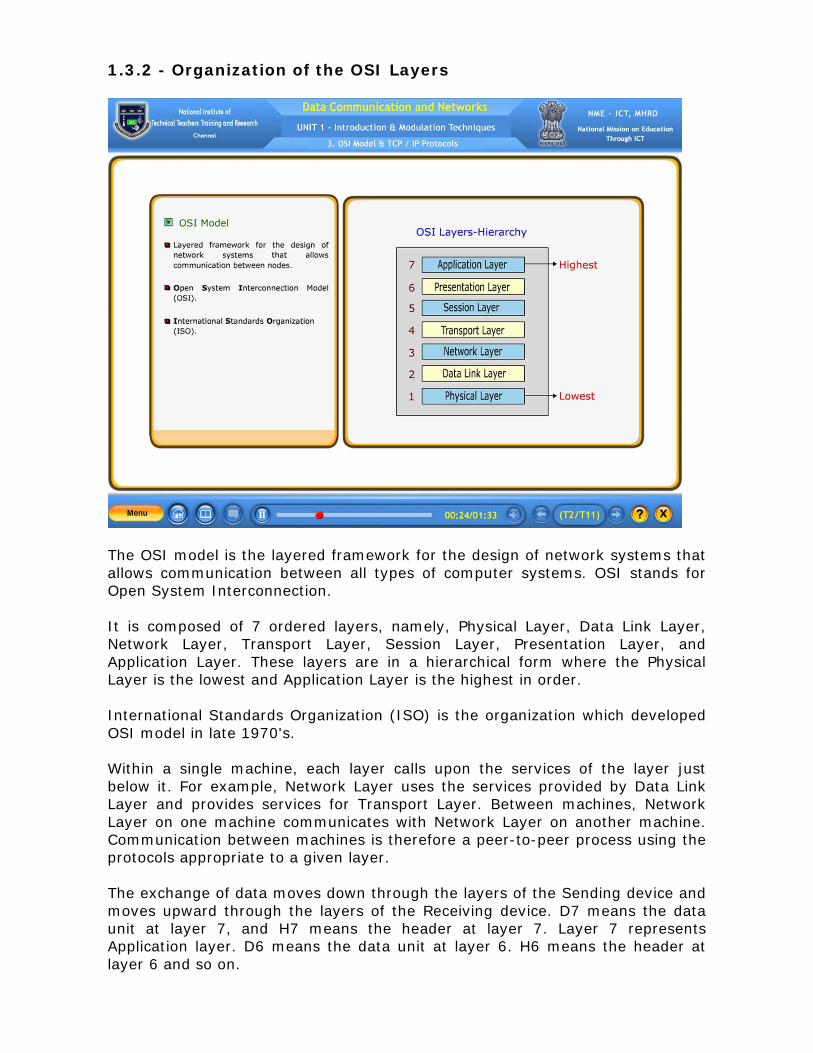
The OSI model is the layered framework for the design of network systems that allows communication between all types of computer systems. OSI stands for Open System Interconnection. It is composed of 7 ordered layers, namely, Physical Layer, Data Link Layer, Network Layer, Transport Layer, Session Layer, Presentation Layer, and Application Layer. These layers are in a hierarchical form where the Physical Layer is the lowest and Application Layer is the highest in order. International Standards Organization (ISO) is the organization which developed OSI model in late 1970's. Within a single machine, each layer calls upon the services of the layer just below it. For example, Network Layer uses the services provided by Data Link Layer and provides services for Transport Layer. Between machines, Network Layer on one machine communicates with Network Layer on another machine. Communication between machines is therefore a peer-to-peer process using the protocols appropriate to a given layer. The exchange of data moves down through the layers of the Sending device and moves upward through the layers of the Receiving device. D7 means the data unit at layer 7, and H7 means the header at layer 7. Layer 7 represents Application layer. D6 means the data unit at layer 6. H6 means the header at layer 6 and so on.

At each layer, a header is added to the data unit. Usually, the trailer is added only at layer 2 which represents Data Link layer. When the formatted data unit passes through the Physical layer, it is changed into an electromagnetic signal and transported along a Transmission medium. Upon reaching its destination, the signal passes into physical layer and is transformed back into digital form. The data units then move back up through the OSI layers. As each block of data reaches the next higher layer, the headers and trailers attached to it at the corresponding sending layer are removed, and actions appropriate to that layer are taken. By the time it reaches Layer 7, the message is again in a form appropriate to the application and is made available to the recipient. 1.3.3 - Physical Layer The physical layer coordinates the functions required to carry a bit stream over a physical medium. The animation reveals an aspect of data communication in the OSI model, called encapsulation. Encapsulation is the process of being enclosed. At the sender’s end, a data from the data link layer is encapsulated as a packet, after adding header at the physical layer. When the encapsulated packet passes through the physical layer, it is changed into an electromagnetic signal and transported along a Transmission medium. Upon reaching its destination, the signal is transformed back into digital form. The data units then move back up through the OSI layers. The physical layer is also concerned with the physical characteristics of interfaces and medium, representation of bits, data rate, synchronization of bits, line configuration, physical topology, transmission mode. The physical layer defines the characteristics of the interface between the devices and the transmission medium. It also defines the type of transmission medium. The physical layer data consists of a stream of bits with no interpretation. To transmit, bits must be encoded into electrical or optical signals. The physical layer defines the type of encoding. The number of bits sent each second is also defined by the physical layer. The sender and receiver not only must use the same bit rate but also must be synchronized at the bit level. The physical layer is concerned with the connection of devices to the media. Devices can be connected by different types of physical topologies. The physical layer also defines the direction of transmission between two devices, namely simplex, half-duplex, or full-duplex. 1.3.4 - Data Link Layer The data link layer moves frames from one node to the next. It transforms the physical layer from a raw transmission facility to a reliable link. The data from the Network layer descends to the Data Link layer. At this layer, a header H2 and a trailer T2 is added to the data unit. Upon reaching its destination, the data units then ascend through the OSI layers.

As each block of data reaches the next higher layer, the headers and trailers attached to it at the corresponding sending layer are removed, and acti-ons appropriate to that layer are taken. The animation shows the relationship of the data link layer to the network and physical layers. The responsibilities of the data link layer include framing, physical addressing, flow control, error control, and access control. The data link layer divides the stream of bits received from the network layer into manageable data units called frames. If frames are to be distributed to different systems on the network, the data link layer adds a header and a trailer to the frame to define the sender and receiver of the frame. If the rate at which the data are absorbed by the receiver is less than the rate at which data are transmitted by the sender, the data link layer imposes a flow control mechanism to avoid overwhelming the receiver. The data link layer adds reliability to the physical layer by adding mechanisms to detect and retransmit damaged or lost frames. Error control is normally achieved through a trailer added to the end of the frame. When two or more devices are connected to the same link, data link layer protocols are necessary to determine which device has control over the link at any given time. 1.3.5 - Network Layer A packet is a combination of a header and data. The network layer is responsible for the delivery of individual packets from the source to the destination. The data from the transport layer moves down to the network layer. At this layer, a header H3 is added to the packet, and then descends to Data Link layer. Upon reaching its destination, the header attached to it at the corresponding sending layer is removed, and then the data unit ascends to the Transport layer. The animation shows the relationship of the network layer to the data link and transport layers. The data link layer oversees the delivery of the packet between two systems on the same network, whereas, the network layer delivers packet between two systems connected across different networks. If two systems are connected to the same link, there is usually no need for a network layer. However, if the two systems are attached to different networks with connecting devices between the networks, there is often a need for the network layer to accomplish source-to-destination delivery. One of the main responsibilities of the network layer is to add a header to the packet coming receiver. from the upper layer that includes the logical addresses of the sender and The other responsibility is to provide routing mechanism. When independent networks are connected to create internetworks, the connecting devices, called routers or switches, route or switch the packets to their final destination.
1.3.6 - Transport Layer The transport layer is responsible for the delivery of a message from one process to another. A process is an application program running on a host. The data from the session layer moves down to the transport layer. At this layer, a header H4 is added to the segments and then segments descend to Network layer. Upon reaching its destination, the header attached to the segments is removed, and then the data unit ascends to the Transport layer. The animation shows the relationship of the transport layer to the network and session layers. While the network layer oversees source-to-destination delivery of individual packets, it does not recognize any relationship between those packets. It treats each one independently, as though each piece belonged to a separate message. The transport layer, on the other hand, ensures that the whole message arrives intact and in order. The responsibilities of the transport layer include service-point addressing, segmentation and reassembly, connection control, flow and error control. The transport layer header must include a type of address called a service-point address or port address, for delivering specific processes between computers. The network layer gets each packet to the correct computer and the transport layer gets the entire message to the correct process on that computer. Data is divided into transmittable segments, with each segment containing a sequence number. These numbers enable the transport layer to reassemble the message correctly upon arriving at the destination and to identify and replace packets that were lost in transmission. The transport layer can be either connectionless or connection-oriented. A connectionless transport layer treats each segment as an independent packet and delivers it to the transport layer at the destination machine. A connection-oriented transport layer makes a connection with the transport layer at the destination machine first before delivering the packets. After all the data are transferred, the connection is terminated. Like the data link layer, the transport layer is responsible for flow and error control. The sending transport layer makes sure that the entire data arrives at the receiving transport layer without error. Error correction is usually achieved through retransmission. 1.3.7 - Session Layer The services provided by the first three layers, namely, physical, data link, and network are not sufficient for some processes. The data segments from the presentation layer moves down to the session layer. At this layer, a header H5 is added at the beginning. Between each segment, synchronization points are inserted and then descended to transport layer. Upon reaching its destination, the header attached to the segment is removed, and then the data segments ascend to the presentation layer. The animation shows the relationship of the session layer to the transport and presentation layers. The session layer is the network dialog controller. It establishes, maintains, and synchronizes the interaction among communicating systems.
The responsibilities of the session layer include dialog control, and synchronization. The session layer allows two systems to enter into a dialog. It allows the communication between two processes to take place in either half-duplex, i.e. one way at a time or full-duplex, i.e. two ways at a time mode. The session layer allows a process to add checkpoints, or synchronization points, to a stream of data. For example, if a system is sending a file of 2000 pages, it is advisable to insert checkpoints after every 100 pages to ensure that each 100-page unit is received and acknowledged independently. In this case, if a crash happens during the transmission of page 523, the only pages that need to be resent after system recovery are pages 501 to 523. Pages previous to 501 need not be resent. 1.3.8 - Presentation Layer The presentation layer is concerned with the syntax and semantics of the information exchanged between two systems. Syntax refers to the order in which data is presented. Semantics helps in interpreting a particular pattern and the action to be taken based on that interpretation. The data from the application layer moves down to the presentation layer. At this layer, a header H6 is added at the beginning of the data unit and then descended to session layer. Upon reaching its destination, the header H6, attached to the data unit, is removed, and then the data ascends to the application layer. The animation shows the relationship of the presentation layer to the session and application layers. The responsibilities of the presentation layer include translation, encryption, and compression. The processes of running programs in two systems are usually exchanging information in the form of character strings, numbers, and so on. The information must be changed to bit streams before being transmitted. Because different computers use different encoding systems, the presentation layer is responsible for interoperability between these different encoding methods. The presentation layer at the sender, changes the information from its sender-dependent format into a common format. The presentation layer at the receiver, changes the common format into its receiver-dependent format. To carry sensitive information, a system must be able to ensure privacy. Encryption means that the sender transforms the original information to another form and sends the resulting message out over the network. Decryption reverses the original process to transform the message back to its original form. Data compression reduces the number of bits contained in the information. Data compression becomes particularly important in the transmission of multimedia such as text, audio, and video.
1.3.9 - Application Layer
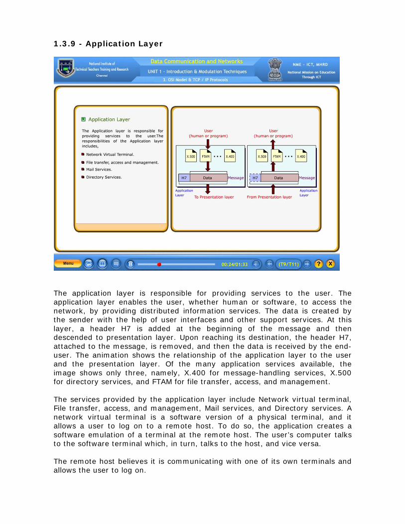
The application layer is responsible for providing services to the user. The application layer enables the user, whether human or software, to access the network, by providing distributed information services. The data is created by the sender with the help of user interfaces and other support services. At this layer, a header H7 is added at the beginning of the message and then descended to presentation layer. Upon reaching its destination, the header H7, attached to the message, is removed, and then the data is received by the end-user. The animation shows the relationship of the application layer to the user and the presentation layer. Of the many application services available, the image shows only three, namely, X.400 for message-handling services, X.500 for directory services, and FTAM for file transfer, access, and management. The services provided by the application layer include Network virtual terminal, File transfer, access, and management, Mail services, and Directory services. A network virtual terminal is a software version of a physical terminal, and it allows a user to log on to a remote host. To do so, the application creates a software emulation of a terminal at the remote host. The user’s computer talks to the software terminal which, in turn, talks to the host, and vice versa. The remote host believes it is communicating with one of its own terminals and allows the user to log on.

This application allows a user to access files in are remote host to make changes or read data, to retrieve files from a remote computer for use in the local computer, and to manage or control files in a remote computer locally. This application provides the basis for e-mail forwarding and storage. This application provides distributed database sources and access for global information about various objects and services. 1.3.10 - Summary of Layers The OSI model is composed of seven ordered layers. The physical layer transmits bits over a medium. It provides mechanical and electrical specifications. The data link organizes bits into frames and provides node-to-node delivery. The network layer moves packets from source to destination and provides internetworking. The transport layer provides reliable process-to-process message delivery and error recovery. The session layer establishes, manages, and terminates sessions. The presentation layer translates, encrypts and compresses data. Finally, the application layer allows access to network resources. Within a single machine, each layer calls upon the services of the layer just below it. The communications between layers are governed by an agreed-upon series of rules and conventions called protocols. Communication between machines is a peer-to-peer process using the protocols appropriate to a given layer. 1.3.11 - TCP / IP Protocol Suite TCP/IP is a five-layer hierarchical protocol suite, developed before the OSI model. Therefore the layers in the TCP/IP protocol suite do not exactly match those in the OSI model. When TCP/IP is compared to OSI, it can be said that the host-to-network layer is equivalent to the combination of the physical and data link layers. The internet layer is equivalent to the network layer, with transport layer in TCP/IP taking care of part of the duties of the session layer. TCP/IP’s application layer is equivalent to the combined session, presentation, and application layers in the OSI model. The first four layers provide physical standards, network interfaces, internetworking, and transport functions that correspond to the first four layers of the OSI model. The three topmost layers in the OSI model, however, are represented in TCP/IP by a single layer called the application layer. TCP/IP is a hierarchical protocol made up of interactive modules, each of which provides a specific functionality. However, the modules are not necessarily interdependent. While the OSI model specifies which functions belong to each of its layers, the layers of the TCP/IP protocol suite contain relatively independent protocols that can be mixed and matched depending on the needs of the system. The term hierarchical means that each upper-level protocol is supported by one or more lower-level protocols.

At the physical and data link layers, TCP/IP does not define any specific protocol. It supports all the standard and proprietary protocols. At the network layer, TCP/IP supports the Internetworking Protocol. IP, in turn, uses four supporting protocols, namely, ARP, RARP, ICMP, and IGMP. ARP stands for Address Resolution Protocol, RARP stands for Reverse Address Resolution Protocol, ICMP stands for Internet Control Message Protocol, and IGMP stands for Internet Group Message Protocol. The Internetworking Protocol is the transmission mechanism used by the TCP/IP protocols. At the transport layer, TCP/IP defines three protocols, namely, TCP, UDP, and SCTP. TCP stands for Transmission Control Protocol, UDP stands for User Datagram Protocol, and SCTP stands for Stream Control Transmission Protocol. At the network layer, the main protocol defined by TCP/IP is the Internetworking Protocol, known as IP. UDP and TCP are transport level protocols responsible for delivery of a message from a process to another process. IP is a host-to-host protocol, meaning that it can deliver a packet from one physical device to another. A new transport layer protocol, SCTP, has been devised to meet the needs of some newer applications. The application layer in TCP/IP is equivalent to the combined session, presentation, and application layers in the OSI model.

1.3.12 Self Test
1. OSI stands for Open Systems ________ model.
(Answer: Interconnection)
2. The application layer is the lowest layer in the OSI model
• True • False (Answer: False)
3. Match the following
(A) Presentation Layer - (1) movements of individual bits
from hop to the next
(B) Session Layer - (2) providing services to the user
(C) Application Layer - (3) delivery of individual packets from the source host to the destination host
(D) Network Layer - (4) delivery of a message from one process to another
(E) Transport Layer - (5) dialog control and synchronization
- (6) Translation, compression, and encryption
[Answer: (A) – (6) (B) – (5) (C) – (2) (D) – (3) (E) – (4)]
4. Encryption is handled by the _________ layer.
A. data link B. transport C. session D. presentation (Answer: presentation)
5. The WWW is an application layer protocol.
• True • False (Answer: True)
1.4 – Analog & Digital Signals 1.4.1 - Analog & Digital Signals
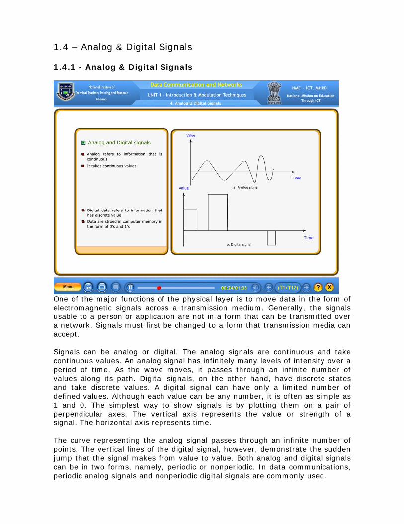
One of the major functions of the physical layer is to move data in the form of electromagnetic signals across a transmission medium. Generally, the signals usable to a person or application are not in a form that can be transmitted over a network. Signals must first be changed to a form that transmission media can accept. Signals can be analog or digital. The analog signals are continuous and take continuous values. An analog signal has infinitely many levels of intensity over a period of time. As the wave moves, it passes through an infinite number of values along its path. Digital signals, on the other hand, have discrete states and take discrete values. A digital signal can have only a limited number of defined values. Although each value can be any number, it is often as simple as 1 and 0. The simplest way to show signals is by plotting them on a pair of perpendicular axes. The vertical axis represents the value or strength of a signal. The horizontal axis represents time. The curve representing the analog signal passes through an infinite number of points. The vertical lines of the digital signal, however, demonstrate the sudden jump that the signal makes from value to value. Both analog and digital signals can be in two forms, namely, periodic or nonperiodic. In data communications, periodic analog signals and nonperiodic digital signals are commonly used.
1.4.2 - Sine Wave A periodic signal completes a pattern within a measurable time frame, called a period. It repeats that pattern over subsequent identical periods. The completion of one full pattern is called a cycle. A non-periodic signal changes without exhibiting a pattern or cycle that repeats over time.
Both analog and digital signals can be periodic or non-periodic. In data communications, periodic analog signals and non-periodic digital signals are commonly used because periodic analog signals need less bandwidth and non-periodic digital signals can represent variation in data.
Periodic analog signals can be classified as simple or composite. A sine wave is the most fundamental form of a periodic analog signal. Unlike a composite signal, it cannot be decomposed into simpler signals. The sine wave is a simple oscillating curve, and its change over the course of a cycle is smooth and consistent, a continuous, rolling flow. Each cycle consists of a single arc above the time axis followed by a single arc below it.
The oscillation of an undamped spring-mass system around the equilibrium is a sine wave. The animation illustrates the sine wave's fundamental relationship to the circle. A sine wave can be represented by three parameters, namely, the peak amplitude, the frequency, and the phase. These three parameters fully describe a sine wave.
1.4.3 – Amplitude Amplitude is the height of the wave. It is the magnitude of change in the oscillating variable with each oscillation within an oscillating system. For example, sound waves in air are oscillations in atmospheric pressure and their amplitudes are proportional to the change in pressure during one oscillation. If a variable undergoes regular oscillations, and a graph of the system is drawn with the oscillating variable as the vertical axis and time as the horizontal axis, the amplitude is visually represented by the vertical distance between the extreme of the curve.
The peak amplitude of a signal is the absolute value of its highest intensity, proportional to the energy it carries. For electric signals, peak amplitude is normally measured in volts. The animation shows two signals and their peak amplitudes. It is a parameter to describe a sine wave.
1.4.4 – Phase Phase describes the position of the waveform relative to time 0. If the wave is perceived as something that can be shifted backward or forward along the time axis, phase describes the amount of that shift. It indicates the status of the first cycle. Phase is measured in degrees or radians, i.e. 360° is 2π rad, 1° is 2π - divided by 360 rad, and 1 rad is 360 – divided by 2π. A phase shift of 90° corresponds to a shift of one-quarter of a period. A phase shift of 180° corresponds to a shift of one-half of a period. And a phase shift of 360° corresponds to a shift of a complete period.
Looking at the animation, it can be said that,
1. A sine wave with a phase of 0° starts at time 0 with a zero amplitude. The amplitude is increasing. 2. A sine wave with a phase of 90° starts at time 0 with a peak amplitude. The amplitude is decreasing. 3. A sine wave with a phase of 180° starts at time 0 with a zero amplitude. The amplitude is decreasing.
Another way to look at the phase is in terms of shift or offset, like –
1. A sine wave with a phase of 0° is not shifted. 2. A sine wave with a phase of 90° is shifted to the left by ¼ cycle. However, note that the signal does not really exist before time 0. 3. A sine wave with a phase of 180° is shifted to the left by ½ cycle. However, note that the signal does not really exist before time 0.
1.4.5 – Period and Frequency Period refers to the amount of time a signal needs to complete 1 cycle. Frequency refers to the number of periods in 1s. Period and frequency are just one characteristic, defined in two ways.
Period is the inverse of frequency, and frequency is the inverse of period. As the formulas shows f = 1/T and T=1/f. The animation shows two signals and their frequencies. The two signals have same amplitude and phase, but different frequencies. In the first case, the frequency is 12 Hz and indicates 12 periods in one second. In the latter case, the frequency is 6 Hz and indicates 6 periods in one second.
Frequency is the rate of change with respect to time. Change in a short span of time means high frequency. Change over a long span of time means low frequency. If a signal does not change at all, its frequency is zero. If a signal changes instantaneously, its frequency is infinite. Frequency is formally expressed in Hertz (Hz), which is cycle per second. Period is formally expressed in seconds. The different Units of period and frequency are shown in a tabular form. The units of period are seconds, milliseconds, microseconds, nanoseconds, and picoseconds. The units of frequency are hertz, kilohertz, megahertz, gigahertz, and terahertz.

1.4.6 – Wavelength
Wavelength is another characteristic of a signal traveling through a transmission medium. Wavelength binds the period or the frequency of a simple sine wave to the propagation speed of the medium. While the frequency of a signal is independent of the medium, the wavelength depends on both the frequency and the medium. Wavelength is a property of any type of signal. In data communications, wavelength is often used to describe the transmission of light in an optical fiber. The wavelength is the distance a simple signal can travel in one period. Wavelength can be calculated if either propagation speed, i.e. the speed of light or the period of the signal is given. However, since period and frequency are related to each other, wavelength can be represented as propagation speed, multiplied by period, which is equal to propagation speed divided by frequency. The propagation speed of electromagnetic signals depends on the medium and on the frequency of the signal. For example, in a vacuum, light is propagated with a speed of 3 into 10 – to the power of 8 meter per second. That speed is lower in air and even lower in cable. The wavelength is normally measured in micrometers or microns, instead of meters. In coaxial or fiber-optic cable, however, the wavelength is shorter because the propagation speed in the cable is decreased.
1.4.7 – Time and Frequency Domains A sine wave is comprehensively defined by its amplitude, frequency, and phase. A sine wave can be shown in two ways, namely, Time-domain plot and Frequency-domain plot. The time-domain plot shows changes in signal amplitude with respect to time. It is an amplitude-versus-time plot. Phase is not explicitly shown on a time-domain plot. On the other hand, in frequency-domain plot, the relationship between amplitude and frequency is shown. A frequency-domain plot is concerned with only the peak value and the frequency. Changes of amplitude during one period are not shown. The animation shows a signal in both the time and frequency domains. It is obvious that the frequency domain is easy to plot and conveys the information than in a time domain plot. The advantage of the frequency domain is that one can immediately see the values of the frequency and peak amplitude. A complete sine wave is represented by one spike. The position of the spike shows the frequency, and its height shows the peak amplitude. 1.4.8 – Composite Signals So far, simple sine waves were focused largely. Simple sine waves have many applications in daily life. A single sine wave can be sent to carry electric energy from one place to another. For example, the power company sends a single sine wave with a frequency of 50 Hz to distribute electric energy to houses and businesses. As another example, a single sine wave is used to send an alarm to a security center when a burglar opens a door or window in the house. In the first case, the sine wave is carrying energy. In the second, the sine wave is a signal of danger. If only one single sine wave is used to convey a conversation over the phone, one would just hear a buzz. A single sine wave would make no sense and carry no information. Instead, a composite signal must be send to communicate data. A composite signal is made of many simple sine waves. In the early 1900s, the French mathematician Jean-Baptiste Fourier showed that any composite signal is actually a combination of simple sine waves with different frequencies, amplitudes, and phases. A composite signal can be periodic or nonperiodic. A periodic composite signal can be decomposed into a series of simple sine waves with discrete frequencies – frequencies that have integer values. A nonperiodic composite signal can be decomposed into a combination of an infinite number of simple sine waves with continuous frequencies, frequencies that have real values.
1.4.9 – Decomposition of a Composite periodic Signal It is very difficult to manually decompose this signal into a series of simple sine waves. However, there are tools, both hardware and software, that can help in doing the job. The main concern is not on how it is done but on the end-result. The animation shows the result of decomposing the above signal in both the time and frequency domains.
The amplitude of the sine wave with frequency f is almost the same as the peak amplitude of the composite signal. The amplitude of the sine wave with frequency 3f is one-third of that of the first, and the amplitude of the sine wave with frequency 9f is one-ninth of the first.
The frequency of the sine wave with frequency f is the same as the frequency of the composite signal. It is called the fundamental frequency, or first haramonic. The sine wave with frequency 3f has a frequency of 3 times the fundamental frequency. It is called the third harmonic. The third sine wave with frequency 9f has a frequency of 9 times the fundamental frequency. It is called the ninth harmonic.
Note that the frequency decomposition of the signal is discrete. It has frequencies f, 3f, and 9f. Because f is an integral number, 3f and 9f are also integral numbers. There are no frequencies such as 1.2f or 2.6f. The frequency domain of a periodic composite signal is always made of discrete spikes. 1.4.10 – Time & Frequency Domains of a non-periodic Signal A nonperiodic composite signal can be a signal created by a microphone or a telephone set when a word or two is pronounced. The animation shows a nonperiodic composite signal. In this case, the composite signal cannot be periodic, because that implies that the same word or words are repeating with exactly the same tone.
In a time-domain representation of this composite signal, there are an infinite number of simple sine frequencies. Although the number of frequencies in a human voice is infinite, the range is limited. A normal human being can create a continuous range of frequencies between 0 and 4 kHz. Note that the frequency decomposition of the signal yields a continuous curve. There are an infinite number of frequencies between 0.0 and 4000.0 real values. To find the amplitude related to frequency f, draw a vertical line at f to intersect the envelope curve. The height of the vertical line is the amplitude of the corresponding frequency.
1.4.11 – Bandwidth One characteristic that measures network performance is bandwidth. However, the term can be used in two different contexts with two different measuring values. They are bandwidth in hertz and bandwidth in bits per second. Bandwidth in Hertz is the range of frequencies contained in a composite signal or the range of frequencies a channel can pass. For example, the bandwidth of a subscriber telephone line is 4kHz. Bandwidths in Bits per Seconds refer to the number of bits per second that a channel, a link, or even a network can
transmit. For example, the bandwidth of a Fast Ethernet network is a maximum of 100 Mbps. This means that this network can send 100 Mbps.
The bandwidth of a composite signal is the difference between the highest and the lowest frequencies contained in that signal. It is the range of frequencies contained in a composite signal. The bandwidth is normally a difference between two numbers.
The concept of bandwidth can be understood with the help of animation that depicts two composite signals, one periodic and the other nonperiodic. Both composite signal contains frequencies between 1000 and 5000, its bandwidth is 5000-1000, equals to 4000. The bandwidth of the periodic signal contains all integer frequencies between 1000 and 5000. The bandwidth of the nonperiodic signals has the same range, but the frequencies are continuous.
1.4.12 – Digital Signal Terminologies In addition to being represented by an analog signal, information can also be represented by a digital signal. For example, a 1 can be encoded as a positive voltage and a 0 as zero voltage. A digital signal can have more than two levels. The animation shows two signals, one with two levels and the other with four. 1 bit per level is sent in the first case and 2 bits per level in the second case. Most digital signals are nonperiodic, and thus period and frequency are not appropriate characteristics. Another term – bit rate, instead of frequency, is used to describe digital signals. The bit rate is the number of bits sent in 1 second, expressed in bits per second. The distance one cycle occupies on the transmission medium is called wavelength for an analog signal. Something similar can be defined for a digital signal, using a term called bit length. The bit length is the distance one bit occupies on the transmission medium. The formula for calculating the bit length is as follows – Bit length equals to Propagation speed, multiplied by bit duration. Transmission of digital signals can occur in two different ways, either by baseband transmission or by broadband transmission. In baseband transmission, digital signal is sent over a channel without converting the digital signal to an analog signal. Baseband transmission requires a channel with a bandwidth that starts from zero. Such channel is called low-pass channel. On the other hand, in broadband transmission, the digital signal is converted into an analog signal for transmission. A channel with a bandwidth that does not start from zero is needed for broadband transmission. Such channel is called bandpass channel. If the available channel is a bandpass channel, the digital signal can’t be sent directly. The signal has to be converted to an analog signal before transmission. In general, Bandpass channel is more available than a low-pass channel.

1.4.13 – Transmission Impairment Signals travel through transmission media, which are not perfect. The imperfection causes signal impairment. This means that the signal at the beginning of the medium is not the same as the signal at the end of the medium. What is sent is not what is received. Three causes of impairment are attenuation, distortion, and noise. Attenuation means a loss of energy. When a signal, simple or composite, from Point 1, travels through a medium, it loses some of its energy in overcoming the resistance of the medium. To compensate for this loss, amplifiers are used to amplify the signal, thereby making the received signal at Point 3, look similar to the original signal at Point 1. A wire carrying electric signals gets warm, if not hot, after a while. Some of the electrical energy in the signal is converted to heat. This is due to resistance of the medium. The animation has shown the effect of attenuation and amplification.
Distortion means that the signal changes its form or shape. Distortion can occur in a composite signal made of different frequencies. Each signal component has its own propagation speed through a medium and therefor, its own delay in arriving at the final destination. Differences in delay may create a difference in phase if the delay is not exactly the same as the period duration. In other words, signal components at the receiver have phases different from what they had at the sender. The shape of the composite signal is therefore not the same. The animation shows the effect of distortion on a composite signal.
Noise is another cause of impairment. Point 1 and Point 2 are connected by a medium. Point 1 transmits signal through the medium. Noise gets added in the middle, thereby making the received signal at Point 2 different from the original signal. Several types of noise, such as thermal noise, induced noise, crosstalk, and impulse noise, may corrupt the signal.
1.4.14 – Throughput
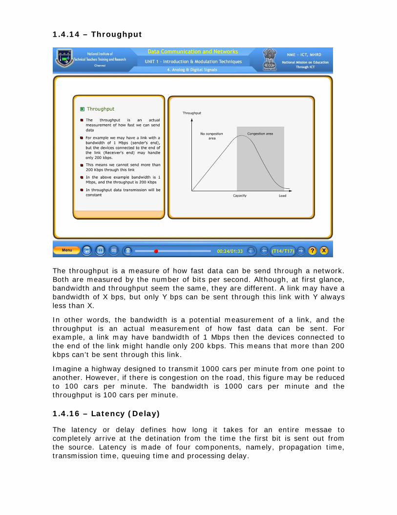
The throughput is a measure of how fast data can be send through a network. Both are measured by the number of bits per second. Although, at first glance, bandwidth and throughput seem the same, they are different. A link may have a bandwidth of X bps, but only Y bps can be sent through this link with Y always less than X.
In other words, the bandwidth is a potential measurement of a link, and the throughput is an actual measurement of how fast data can be sent. For example, a link may have bandwidth of 1 Mbps then the devices connected to the end of the link might handle only 200 kbps. This means that more than 200 kbps can’t be sent through this link.
Imagine a highway designed to transmit 1000 cars per minute from one point to another. However, if there is congestion on the road, this figure may be reduced to 100 cars per minute. The bandwidth is 1000 cars per minute and the throughput is 100 cars per minute. 1.4.16 – Latency (Delay) The latency or delay defines how long it takes for an entire messae to completely arrive at the detination from the time the first bit is sent out from the source. Latency is made of four components, namely, propagation time, transmission time, queuing time and processing delay.

Propagation time measures the time required for a bit to travel from the source to the destination. The propagation time is calculated by dividing the distance by the propagation speed. The propagation speed of electromagnetic signals depends on the medium and on the frequency of the signal. For example, in a vacuum, light is propagated with a speed of 3 into 10 to the power of 8, meters per second. It is lower in air and is much lower in cable.
In data communications, one bit alone won’t be sent a message. The first bit may take a time equal to the propagation time to reach its destination. The last bit also may take the same amount of time. However, there is a time between the first bit leaving the sender and the last bit arriving at the receiver. The first bit leaves earlier and arrives earlier. The last bit leaves later and arrives later. The time required for transmission of a message depends on the size of the message and the bandwidth of the channel.
The third component in latency is the queuing time. It is the time needed for each intermediate or end device to hold the message before it can be processed. The queuing time is not a fixed factor. It changes with the load imposed on the network. When there is heavy traffic on the network, the queuing time increases. An intermediate device, such as a router, queues the arrived messages and processes them one by one. If there are many messages, each message will have to wait.
1.4.17 – Jitter Another performance issue that is related to delay is jitter. Jitter is the variation in delay for packets belonging to the same flow. Jitter is a problem that occurs when different packets of data encounter different delays. For example, if four packets depart at times 0, 1, 2, 3 and arrive at 20, 21, 22, 23, all have the same delay, 20 units of time. On the other hand, if the above four packets arrive at 21, 23, 21, and 28, they will have different delays – 21, 22, 19, 24. For applications such as audio and video, the first case is completely acceptable, the second case is not. For these applications, it does not matter if the packets arrive with a short or long delay as long as the delay is the same for all packets. For this application, the second case is not acceptable. Jitter is defined as the variation in the packet delay. High jitter means the difference between delays is large. Low jitter means the variation is small.

1.4.18 – Self Test 1. A sine wave can be represented by three parameters namely, peak amplitude, ________ and phase.
(Answer: frequency)
2. Phase describes the position of a waveform relative to time zero.
• True • False (Answer: True)
3. Frequency is measured in
A. Hertz B. Volts C. decibel D. unit (Answer: Hertz)
4. Frequency and period are the inverse of the each other.
• True • False (Answer: True)
5. Match the following
(A) Bit Rate - (1) loss of energy
(B) Bit Length - (2) number of bits sent in one second
(C) Attenuation - (3) signal changes its form or shape
(D) Distortion - (4) It is the distance one bit occupies on the transmission medium (E) Noise - (5) it measures network performance
- (6) thermal noise, induced noise, and crosstalk
[Answer (A) – (2) (B) – (4) (C) – (1) (D) – (3) (E) – (6)]
1.5 – Modulation Techniques 1.5.1 - Analog – to – Analog Conversion
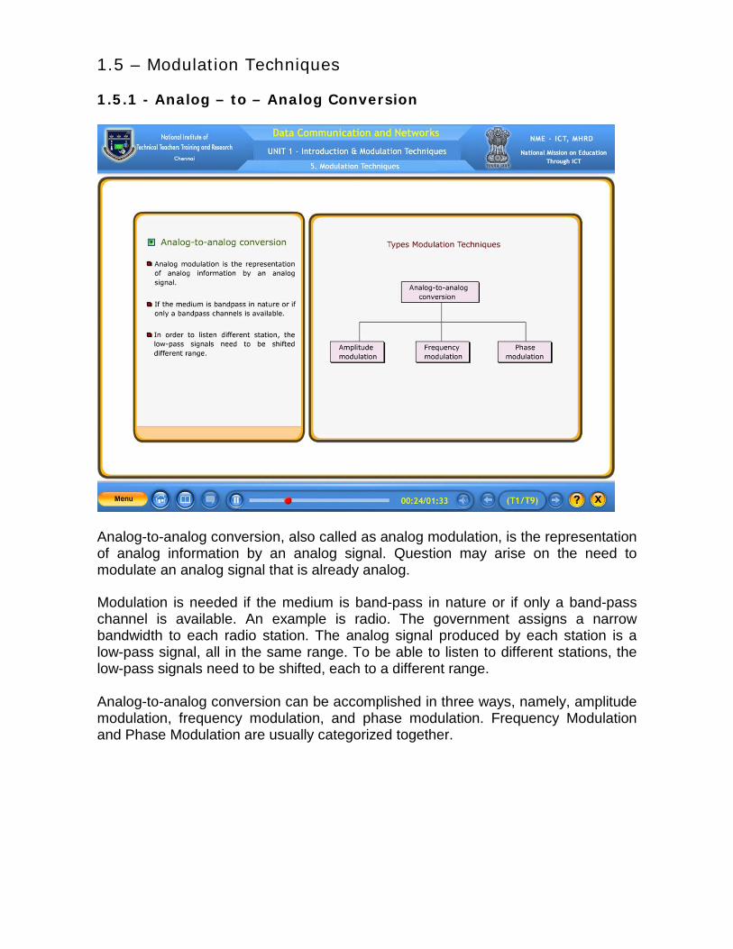
Analog-to-analog conversion, also called as analog modulation, is the representation of analog information by an analog signal. Question may arise on the need to modulate an analog signal that is already analog. Modulation is needed if the medium is band-pass in nature or if only a band-pass channel is available. An example is radio. The government assigns a narrow bandwidth to each radio station. The analog signal produced by each station is a low-pass signal, all in the same range. To be able to listen to different stations, the low-pass signals need to be shifted, each to a different range. Analog-to-analog conversion can be accomplished in three ways, namely, amplitude modulation, frequency modulation, and phase modulation. Frequency Modulation and Phase Modulation are usually categorized together.
1.5.2 - Amplitude Modulation
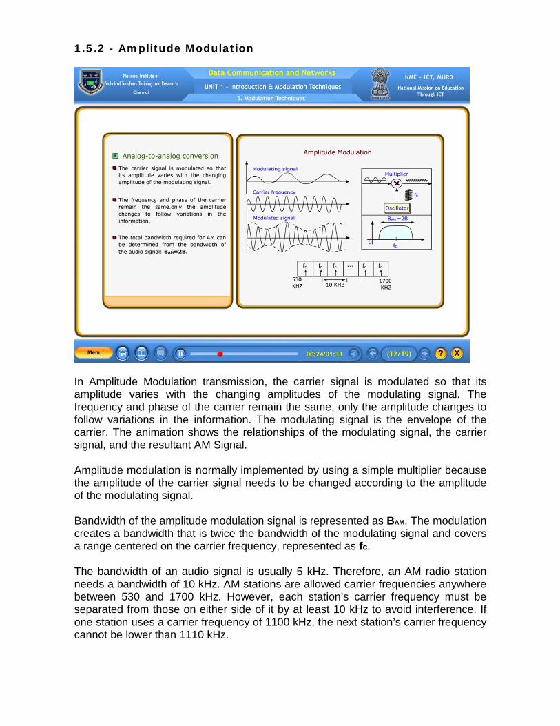
In Amplitude Modulation transmission, the carrier signal is modulated so that its amplitude varies with the changing amplitudes of the modulating signal. The frequency and phase of the carrier remain the same, only the amplitude changes to follow variations in the information. The modulating signal is the envelope of the carrier. The animation shows the relationships of the modulating signal, the carrier signal, and the resultant AM Signal. Amplitude modulation is normally implemented by using a simple multiplier because the amplitude of the carrier signal needs to be changed according to the amplitude of the modulating signal. Bandwidth of the amplitude modulation signal is represented as BAM. The modulation creates a bandwidth that is twice the bandwidth of the modulating signal and covers a range centered on the carrier frequency, represented as fc.
The bandwidth of an audio signal is usually 5 kHz. Therefore, an AM radio station needs a bandwidth of 10 kHz. AM stations are allowed carrier frequencies anywhere between 530 and 1700 kHz. However, each station’s carrier frequency must be separated from those on either side of it by at least 10 kHz to avoid interference. If one station uses a carrier frequency of 1100 kHz, the next station’s carrier frequency cannot be lower than 1110 kHz.

1.5.3 - Frequency Modulation In Frequency modulation transmission, the frequency of the carrier signal is modulated to follow the changing amplitude of the modulating signal. The peak amplitude and phase of the carrier signal remain constant, but as the amplitude of the information signal changes, the frequency of the carrier changes correspondingly. The animation shows the relationships of the modulating signal, the carrier signal, and the resultant FM Signal.
Frequency modulation is normally implemented by using a voltage-controlled oscillator. The frequency of the oscillator changes according to the input voltage which is the amplitude of the modulating signal.
The actual bandwidth is difficult to determine exactly, but it can be shown empirically that it is several times that of the analog signal. The total bandwidth required for FM can be determined by BFM, equal to two into one plus beta into B, where B represents the bandwidth of the signal and beta is a factor that depends on modulation technique and with a common value of 4. The Bandwidth for FM signal covers a range centered on the carrier frequency, represented as fc.
The bandwidth of an audio signal broadcast in stereo is almost 15 kHz. FM stations are allowed carrier frequencies anywhere between 88 and 108 Mega hertz’s. Stations must be separated by at least 200 kHz to keep their bandwidths from overlapping. To create even more privacy, only alternate bandwidth allocations may be used. The others remain unused to prevent any possibility of two stations interfering with each other. 1.5.4 - Phase Modulation In Phase modulation transmission, the phase of the carrier signal is modulated to follow the changing voltage level of the modulating signal. The peak amplitude and frequency of the carrier signal remain constant, but as the amplitude of the information signal changes, the phase of the carrier changes correspondingly.
It can be proved mathematically that Phase Modulation is the same as Frequency Modulation, except for one difference. In Frequency modulation, the instantaneous change in the carrier frequency is proportional to the amplitude of the modulating signal. In Phase modulation, the instantaneous change in the carrier frequency is proportional to the derivative of the amplitude of the modulating signal. The animation shows the relationships of the modulating signal, and the resultant Phase modulation signal.
Phase modulation is normally implemented by using a voltage-controlled oscillator along with a derivative. The frequency of the oscillator changes according to the derivative of the input voltage which is the amplitude of the modulating signal.
The actual bandwidth is difficult to determine exactly, but it can be shown empirically that it is several times that of the analog signal. Although, the formula shows the same bandwidth for Frequency modulation and Phase modulation, the value of beta is lower in the case of Phase modulation which is around 1 for narrowband and 3 for wideband. 1.5.5 - Analog – to – Digital Conversion
Analog-to-digital conversion is the representation of analog information by a digital signal. In analog-to-digital conversion, a continuous quantity is converted to a discrete time digital representation. In analog-to-digital conversion, an input analog voltage or current is converted to a digital number proportional to the magnitude of the voltage or current.
A digital signal is superior to an analog signal. The tendency today is to change an analog signal to digital data. The bandwidth of an analog system is limited by the physical capabilities of the analog circuits and recording medium.
Analog-to-digital conversion can be accomplished in two ways, namely, pulse code modulation, and delta modulation. After the digital data are created, it can be stored in digital format like CD, DVD, or hard drive. 1.5.6 - Pulse Code Modulation (PCM) Components
The most common technique to change an analog signal to digital data is called pulse code modulation. Pulse code modulation is abbreviated as PCM. A PCM encoder has three processes, namely, sampling, quantizing, and encoding.
The first process in PCM is sampling. Sampling is the reduction of a continuous signal to a discrete signal. In the sampling process, the analog signal is sampled. The second process in PCM is quantizing. The sampling process is sometimes referred to as pulse amplitude modulation, which is abbreviated as PAM.
Quantization is the process of mapping a large set of input values to a smaller set – such as rounding values to some unit of precision. In the quantizing process, the sampled signal is quantized. The final process in PCM is encoding. Encoding allows the quantized values of sampled signal to be converted into a construct that can be stored and recalled later. During encoding process, the quantized values are encoded as streams of bits.
A Pulse Code Modulation stream is a digital representation of an analog signal, in which the magnitude of the analogue signal is sampled regularly at uniform intervals, with each sample being quantized to the nearest value within a range of digital steps.
1.5.7 - Sampling methods for PCM
The first step in Pulse Code Modulation is sampling. The analog signal is sampled every Ts second, where Ts is the sample interval or period. The inverse of the sampling interval is called the sampling rate or sampling frequency and denoted by fs, where fs=1/Ts.
There are three sampling methods, namely, ideal, natural, and flat-top. In ideal sampling, pulses from the analog signal are sampled. This is an ideal sampling method and cannot be easily implemented. In natural sampling, a high-speed switch is turned on for only the small period of time when the sampling occurs. The result is a sequence of samples that retains the shape of the analog signal. The most common sampling method, called sample and hold, however, creates flat-top samples by using a circuit.
According to the Nyquist theorem, to reproduce the original analog signal, one necessary condition is that the sampling rate be at least twice the highest frequency in the original signal.
The sampling process is also referred as pulse amplitude modulation. However, the resultant output is still an analog signal with non-integral values.
1.5.8 - Delta Modulation
Pulse code modulation is a very complex technique. Other techniques have been developed to reduce the complexity of pulse code modulation. The simplest is delta modulation. Pulse code modulation finds the value of the signal amplitude for each sample. Delta modulation finds the change from the previous sample.
Delta modulation finds the change from the previous sample. There are no code words and bits are sent one after another. The modulation process records the small positive or negative changes, called delta. If the delta is positive, the process records a 1. If it is negative, the process records a 0. However, the process needs a base against which the analog signal is compared. The modulator builds a second signal that resembles a staircase. Finding the change is then reduced to comparing the input signal with the gradually made staircase signal. 1.5.9 - Delta Modulation Components
The modulator is used at the sender site to create a stream of bits from an analog signal. The modulator, at each sampling interval, compares the value of the analog signal with the last value of the staircase signal. If the amplitude of the analog signal is larger, the next bit in the digital data is 1, otherwise, it is 0. The output of the comparator, however, also makes the staircase itself. If the next bit is 1, the staircase maker moves the last point of the staircase signal delta up. If the next bit is 0, it moves the last point of the staircase signal delta down. Note that a delay unit is needed to hold the staircase function for a period between two comparisons.

The demodulator takes the digital data and using the staircase maker and the delay unit, creates the analog signal. The created analog signal, however, needs to pass through a low-pass filter for smoothing.
A better performance can be achieved if the value of 8 is not fixed. In adaptive delta modulation, the value of 8 changes according to the amplitude of the analog signal.
It is obvious that DM is not perfect. Quantization error is always introduced in the process. The quantization error of DM, however, is much less than for PCM.

1.5.10 – Self Test
1. Analog to digital conversion is accomplished by pulse code modulation and ________ modulation.
(Answer: delta)
2. Sampling, quantizing, and encoding are involved in pulse code modulation.
• True • False (Answer: True)
3. Amplitude modulation, frequency modulation and phase modulation are
used to accomplish
A. analog-to-analog conversion B. analog-to-digital conversion C. digital-to-analog conversion D. digital-to-digital conversion (Answer: analog-to-analog conversion)
4. To reproduce the original analog signal, the sampling rate must be at least twice the highest frequency in the original signal.
• True • False (Answer: True)
5. Match the following
(A) Amplitude Modulation - (1) variation in amplitude and
frequency, phase is constant
(B) Frequency Modulation - (2) variation in amplitude, frequency
and phase are constant
(C) Phase Modulation - (3) variation in frequency,
amplitude and phase are constant
(D) Pulse Code Modulation - (4) variation in phase, amplitude
and frequency are constant
(E) Delta Modulation - (5) sampling, quantizing, and
encoding
- (6) analog to digital conversion
(A) – (2) (B) – (3) (C) – (4) (D) – (5) (E) – (6)
(Answer: 2 3 4 5 6)

2 - Transmission Media & Network Devices 2.1 Guided Media 2.1.1 Overview on Transmission Media Having discussed about the Physical layer in OSI model, this module discusses about Transmission Media. Transmission media are actually located below the physical layer and are directly controlled by the physical layer. Here, the animation shows the position of transmission media in relation to the physical layer. One could say that transmission media belong to layer zero.
A Transmission Medium can be defined as anything that can carry information from a source to a destination. For example, the transmission medium for 2 people having a dinner conversation is the air. For a written message, the transmission medium might be a mail carrier, a truck, or an airplane.
In data communications, the definition of the information and the transmission medium is more specific. The transmission medium is usually free space, metallic cable, or fiber-optic cable. The information is usually a data signal.
2.1.2 Classes of Transmission Media The use of long-distance communication using electric signals started with the invention of the Telegraph in the 19th century. Telephone, during 1896, also used a metallic medium for communication. However, the communication was unreliable due to the poor quality of wires.
We have come a long way in inventing better metallic media. The use of optical fibres has increased the data rate incredibly. Free space is used more efficiently for communication.
In telecommunications, transmission media can be divided into 2 broad categories, namely, guided and unguided. Guided media include twisted-pair cable, coaxial cable, and fiber-optic cable. Unguided medium is free space.
Guided Media provides a physical conduit from one device to another. A travelling signal is directed and contained by the physical limits of the medium. Unguided media transport electromagnetic waves without using a physical conductor.
2.1.3 Twisted-Pair Cable Twisted – Pair cable accepts and transports signals in the form of electric current. It consists of two copper conductors, each with its own plastic insulation, twisted together.
One of the wires is used to carry signals to the receiver, and the other is used only as a ground reference. The receiver uses the difference between the two. In addition to the signals sent by the sender, noise and crosstalk may affect both wires and create unwanted signals.

If the two wires are parallel, the effect of these unwanted signals is not the same in both wires because they are at different locations relative to the noise sources. This results in a difference at the receiver. Twisting makes it probable that both wires are equally affected by external noise. The unwanted signals are mostly canceled out. The number of twists per unit of length has some effect on the quality of the cable. 2.1.4 Unshielded Vs Shielded Twisted-Pair Cable
The most common twisted-pair cable used in communications is Unshielded Twisted-Pair cable. IBM has produced a version of twisted-pair cable for its use called Shielded twisted-pair.
Shielded twisted-pair cable has a metal shield or braided-mesh covering that encases each pair of insulated conductors. The illustration shows the difference between Unshielded and Shielded Twisted-Pair.
Although metal shield improves the quality of cable by preventing the penetration of noise or crosstalk, it is bulkier and more expensive. Our discussion focuses primarily on Unshielded Twisted-Pair because Shielded Twisted-Pair is seldom used outside of IBM.
The Electronic Industries Association (EIA) has developed standards, to classify Unshielded Twisted-Pair cable into seven categories, suitable for specific uses.

2.1.5 Unshielded Twisted-Pair Cable The most common Unshielded Twisted-Pair connector is RJ45. RJ stands for registered jack. Inside the ethernet cable, there are 8 color coded wires, with all eight pins used as conductors. These wires are twisted into 4 pairs and each pair has a common color theme. RJ45 specifies the physical male and female connectors as well as the pin assignments of the wires. RJ45 uses 8P8C modular connector, which stands for 8 Position 8 Contact. It is a keyed connector which means that the connector can be inserted only in a single way. RJ45 is used almost exclusively to refer to Ethernet-type computer connectors. 2.1.6 Coaxial Cable
Coaxial cable carries signals of higher frequency ranges than those in twisted-pair cable because the two media are constructed quite differently. Coaxial cable is an electrical cable, encasing of tubular layers. The whole cable is protected by a plastic cover. This plastic cover, in turn, encloses a tubular insulating sheath. The insulating sheath further encloses a metallic conductor.

The outer metallic wrapping serves both as a shield against noise as well as acts as the second conductor of the circuit. The metallic conductor encircles another insulating sheath. This dielectric sheath encloses the central core conductor of solid wire. The wire is usually copper.
The term coaxial comes from the inner conductor and the outer shield, sharing the same geometric axis.
2.1.7 Coaxial Cable Connectors
Coaxial connectors are needed to connect coaxial cable to devices. The most common type of connector used today is the Bayone-Neil-Concelman, in short, BNC connector.
The three popular types of connectors are: the BNC connector, the BNC T connector, and the BNC terminator. The BNC connector is used to connect the end of the cable to a device, such as a TV set. The BNC T connector is used in Ethernet networks to branch out to a connection to a computer or other device. The BNC terminator is used at the end of the cable to prevent the reflection of the signal.
Coaxial cable was widely used in analog telephone networks and in traditional cable TV network. However, coaxial cable has largely been replaced today with fiber-optic cable due to its higher attenuation.
2.1.8 Fiber-Optic cable (Bending of light ray) A fiber-optic cable is made of glass or plastic and transmits signals in the form of light. To understand optical fiber, several aspects of the nature of light have to be explored. One aspect of light is that Light travels in a straight line as long as it is moving through a single uniform substance.
In this image, the straw looks bend because of change in the direction of the light ray. If a ray of light traveling through one substance suddenly enters another substance of a different density, the ray changes direction. Let us observe how a ray of light changes direction, when going from a denser to a less dense substance, using an animation.
It’s important to describe certain terms that are used in this animation, like Angle of Incidence and Critical angle. Angle of Incidence is the angle the ray makes with the line perpendicular to the interface between the two substances. Critical angle is the angle of incidence at which maximum refraction occurs. Critical angle is a property of the substance, and its value differs from one substance to another.
In the 1st case, the angle of incidence (I) is less than the critical angle and hence the ray refracts and moves closer to the surface. In the 2nd case, the angle of incidence is equal to the critical angle, the light bends along the interface. In the 3rd case, the angle of incidence is greater than the critical angle, the ray reflects, makes a turn, and travels again in the denser substance. Optical fibers use reflection to guide light through a channel.
2.1.9 Fiber-Optic cable (Cross section) An optical fiber is a thin, flexible, transparent fiber that acts as a waveguide, or "light pipe", to transmit light between the two ends of the fiber. Optical fiber permits transmission over longer distances and at higher bandwidths than other forms of communication.
Optical fibers use reflection to guide light through a channel. A glass or plastic core is surrounded by a cladding of less dense glass or plastic. The difference in density of the two materials must be such that a beam of light moving through the core is reflected of the cladding instead of being refracted into it. Light is kept in the core by total internal reflection. This causes the fiber to act as a waveguide.
Fibers are used instead of metal wires because signals travel along them with less loss and are also immune to electromagnetic interference.
2.1.10 Fiber-Optic cable (Propagation modes) For propagating light along optical media, current technology supports two propagation modes, namely - Multimode and Single mode. Multimode can be implemented in 2 forms, namely – Step-index and Graded-index. In Multimode, multiple beams from a light source move through core in different paths.
Optical fibers are defined by the ratio of the diameter of their core to the diameter of their cladding, both expressed in micrometers. In Multimode step-index fiber, the fiber type is 200 by 380, with 200 indicating the diameter of core and 380 indicating the diameter of the cladding.
The index of refraction is related to density. The density of the core remains constant from the center to the edges. A beam of light moves through this constant density in a straight line until it reaches the interface of the core and the cladding. At the interface, there is an abrupt change due to a lower density and this alters the angle of the beam’s motion. The term “Step index” refers to the suddenness of this change, which contributes to the distortion of the signal as it passes through the fiber.
A second type of fiber, called multimode graded-index fiber, has fiber type of 50 by 125, with 50 indicating the diameter of core and 125 indicating the diameter of the cladding. A graded-index fiber, with its varying densities, decreases the distortion of the signal through the cable. Density is highest at the center of the core and decreases gradually to its lowest at the edge. The animation shows the impact of this variable density on the propagation of light beams.
Single-mode uses step-index fiber with a much smaller diameter than that of multimode fiber and with substantially lower density i.e. with lower index of refraction. In this single-mode fiber, the diameter of the core is less than 10 micrometer and the diameter of the cladding is 125 micrometers. The decrease in density results in a critical angle that is close enough to 90 degree to make the propagation of beams almost horizontal. In this case, propagation of different beams is almost identical, and delays are negligible. All the beams arrive at the destination “together” and can be recombined with little distortion to the signal.

2.1.11 Fiber-Optic cable (Fiber construction) The fiber optic cable is a composition of various tubular layers. The outer jacket is made of either PVC or Teflon. Inside the jacket are Kevlar strands to strengthen the cable. Kevlar is a strong material used in the fabrication of bulletproof vests. Below the Kevlar is another plastic coating to cushion the fiber. The fiber is at the center of the cable, and it consists of cladding and core.
2.1.12 Fiber-Optic cable connectors
Joining lengths of optical fiber is more complex than joining electrical cable. The ends of the fibers must be carefully cleaved, and then spliced together either mechanically or by fusing them together with heat. Special optical fiber connectors are used to make removable connections. There are three types of Connectors for fiber optic cable, namely, Subscriber Channel Connector, Straight – Tip Connector and MT – RJ connector. The Subscriber Channel Connector is used for cable TV. It uses a push /pull locking system. The Straight – Tip Connector is used for connecting cable to networking devices. It uses a bayonet locking system and is more reliable than Subscriber Channel Connector. MT – RJ is a connector that is the same size as RJ45. Fiber-optic cable is often found in backbone networks because its wide bandwidth is cost-effective and its immunity to electromagnetic interference.

2.1.13 – Self Test
1. Twisted-pair cable accepts and transports signal in the form of _________.
A. electromagnetic Waves B. electric current C. infrared D. microwave (Answer: electric current)
2. Transmission media are actually located below the Physical layer and are
directly controlled by the Data link layer.
• True • False (Answer: True)
3. The most common Unshielded Twisted-Pair connector is _________.
A. RJ11 B. RJ45 C. RG45 D. RG11 (Answer: RJ45)
4. Unguided media transports electromagnetic waves without using any physical
_________ . (Answer: conductor)
5. Coaxial cable carries signals of higher frequency ranges than those in twisted-pair cable because the two media are constructed quite differently.
• True • False (Answer: True)
6. Optical fibers use _________ to guide light through a channel. (Answer: reflection)
2.2 Unguided Media 2.2.1 Wireless Communication (Electromagnetic spectrum) Having discussed about Guided media that transports data signals using a physical conductor, this module focuses on unguided media. The unguided media is the wireless media. It simply transports data signals without using any physical conductor. This type of communication is often referred to as Wireless Communication.
Signals are normally broadcast through the air and thus are available to any one who has the device capable of receiving them. Animation shows the part of the electromagnetic spectrum, ranging from 3 kilo Hertz to 900 Tera Hertz which is used for wireless communication.
Although there is no clear-cut demarcation between radio waves and microwaves, electromagnetic waves ranging in frequencies between 3 kHz and 1GHz are normally called radio waves. Waves ranging in frequencies between 1 and 300 GHz are called microwaves.
In the next teaching point, we will discuss about several ways the unguided signals can travel from the source to destination. 2.2.2 Wireless Communication (Propagation Methods) Unguided signals can be travelled from source to the destination in several ways. These ways include ground propagation, sky propagation and line-of-sight propagation.
In the ground propagation, the radio waves travel through the lowest portion of atmosphere, hugging the earth. These very low frequency signals emanate in all directions from transmitting antenna and follow the curvature of planet. Distance depends on the amount of power in the signal. The greater the power, the greater the distance.
In sky propagation, the higher frequency radio waves radiate upward into the ionosphere where they are reflected back to earth. Ionosphere is the layer of atmosphere where particles exist as ions. This type of transmission allows for greater distances with lower output power.
In the line of sight propagation, very high frequency signals are transmitted in straight lines directly from the antenna to antenna. Antennas must be directional, facing each other and either tall enough or close enough together not to be affected by curvature of the earth. The line of sight propagation is tricky as radio transmissions can not be completely focused. Infra red waves are used for the short range communication such as those between a PC and the peripheral device.

2.2.3 Wireless Communication (Taxonomy)
Wireless transmission waves are used to transfer information over short and long distances. The term “Wireless” is used to describe communication in which electromagnetic waves carry a signal over part or the entire communication path.
Wireless transmission is divided into 3 broad groups. These groups include Radiowave, Microwave, and Infrared wave. Radio waves are used for multicast communications, such as radio and television, and paging systems.
Microwaves are very useful in one-to-one communication between the sender and the receiver. They are used in cellular phones, satellite networks and wireless LANs.
Infrared waves are useless for long-range communication. It can be used for short-range communications. Infrared waves are used for communication between devices such as keyboards, mouse, PCs and printers.

2.2.4 Radio Wave
Radio waves are omni-directional. When an antenna transmits radio waves, they are propagated in all directions. This means that the sending and receiving antennas do not have to be aligned. A sending antenna sends waves that can be received by any receiving antenna. The omni-directional property has a disadvantage, too. The radio waves transmitted by one antenna are susceptible to interference by another antenna that may send signals using the same frequency or band.
Radio waves can travel long distances. This makes radio waves a good candidate for long-distance broadcasting such as AM radio. Radio waves of low and medium frequencies can penetrate walls. This characteristic can be both an advantage and a disadvantage.
It is an advantage because, for example, an AM radio can receive signals inside a building. It is a disadvantage because we cannot isolate a communication to just inside or outside a building. The radio wave band is relatively narrow, just under 1 GHz, compared to the microwave band.
When this band is divided into sub-bands, the sub-bands are also narrow, leading to a low data rate for digital communications.

2.2.5 Microwave
Electromagnetic waves having frequencies between 1 and 300 GHz are called microwaves. Microwaves are unidirectional. When an antenna transmits microwaves, they can be narrowly focused. This means that the sending and receiving antennas need to be aligned.
Two types of antennas are used for microwave communications, namely, the parabolic dish and the horn. A parabolic dish antenna is based on the geometry of a parabola where every line parallel to the line of sight. The parabolic dish works as a funnel, catching a wide range of waves and directing them to a common point. In this way, more of the signal is recovered than would be possible with a single-point receiver.
Outgoing transmissions are broadcast through a horn aimed at the dish. The microwaves hit the dish and are deflected outward in a reversal of the receipt path.
A horn antenna looks like a gigantic scoop. Outgoing transmission are broadcast up a stem and deflected outward in a series of narrow parallel beams by the curved head. Received transmissions are collected by the scooped shape of the horn, in a manner similar to the parabolic dish, and are deflected down into the stem.
The unidirectional property has an obvious advantage. A pair of antennas can be aligned without interfering with another pair of aligned antennas.

2.2.6 Microwave Types There are two types of microwave communication, namely: Terrestrial and Satellite. Terrestrial Microwave communications typically use directional parabolic antennas to send and receive signals in the lower giga hertz range.
The signals are highly focused and the physical path must be in the line-of-sight. Relay towers and repeaters are used to extend signals. Terrestrial microwave communications are used whenever cabling is cost-prohibitive such as in hilly areas or crossing rivers. For example, if two buildings are separated by a public road, we may not be able to get permission to install cable over or under the road. Microwave links would be a good choice in this type of situation.
In Satellite communications, microwave signals at 6 GHz are transmitted from a transmitter on earth to a satellite positioned in space. By the time this signal reaches the satellited it becomes weak as it travels a distance of 36,000 km. The transponder in a satellite amplifies the weak signals and sends them back to the earth at a frequency of 4 GHz. These signals are received at a receiving station on the earth. It may be noted that the transmitting frequency is different from the receiving frequency of the satellite. This is done to avoid interference of the powerful re-transmitted signal with the weak incoming signal.
A major drawback of satellite communications has been the high cost of placing the satellite into its orbit. Necessary security measures need to be taken to prevent unauthorized tampering of information.
2.2.7 Infrared wave Infrared waves, with frequencies from 300 GHz to 400 THz, can be used for short-range communication. Infrared waves, having high frequencies, cannot penetrate walls. This advantageous characteristic prevents interference between one system and another.
A short-range communication system in one room cannot be affected by another system in the next room. The remote controls used on television, VCRs, and stereos use infrared communications. When we use infrared remote control, we do not interfere with the use of the remote by our neighbours.
However, this same characteristic makes infrared signals useless for long-range communication. They are relatively directional, cheap and easy to build but do not pass through solid objects. In addition, we cannot use infrared waves outside a building because the sun’s rays contain infrared waves that can interfere with the communication.
2.2.8 Self Test
1. To transfer information over short and long distances _____________ transmission waves are used.
(Answer: wireless) 2. Infrared waves, with frequencies from 300 GHz to 400 THz, can be used for
short - range communication.
• True • False (Answer: False)
3. Waves ranging in frequencies between _________ are called microwaves.
• 3 GHz and 300 GHz • 1 MHz and 300 MHz • 3 THz and 300 THz • 300 GHz and 400 GHz (Answer: 1MHz and 300 ,MHz)
4. Terrestrial microwave communication, typically use directional_________
antennas to send and receive signals in the lower giga hertz range.
(Answer: parabolic)
5. Radio waves are unidirectional and are propagated in all directions.
• True • False (Answer: True)
6. Match the following
(A) Radio waves - (1) 3 KHz to 900 THz
(B) Infrared Waves - (2) 3 KHz and 1 GHz
(C) Unguided Media - (3) 1 GHz and 300 GHz
(D) Microwaves - (4) 300 GHz to 400 THZ
(E) Wireless Communication - (5) 1 KHz to 300 KHz
- (6) Wireless Media
(A) – (2) (B) – (4) (C) – (6) (D) – (3) (E) – (1)
(Answer: 2 4 6 3 1)
2.3 Network Devices
2.3.1 Introduction to Network Devices
Local Area Networks are connected to one another using connecting devices. Connecting devices can operate in different layers of the Internet model.
Connecting devices are divided into five different categories based on the layer in which they operate in a network. The five categories contain devices which can be defined as –
o Those which operate below the Physical Layer such as a Passive Hub. o Those which operate at the Physical Layer like a Repeater or an Active o Hub. o Those which operate at the Physical and Data Link Layers such as a Bridge o Or a two-layer switch o Those which operate at the Physical, Data Link, and Network Layers such o Or a three - layer switch. o Those which can operate at all five layers such as a Gateway as a router.
In this module, we will discuss about Network devices that operate in different Layers
2.3.2 Repeater Repeaters are network device that operates only in the Physical Layer. Within a network, signals can travel a fixed distance before attenuation weakens the integrity of the data. A repeater receives a signal just before it becomes too weak or corrupted. It regenerates the original bit pattern and sends the refreshed signal.
A repeater can extend the physical length of a single network. It can overcome the cable length restriction in the network by dividing the cable into segments. Repeaters are installed between segments and act as a two-port node. When it receives a frame from any of the ports, it regenerates and forwards it to the other port.
It is tempting to compare a repeater to an amplifier, but the comparison is inaccurate. An amplifier cannot discriminate between the intended signal and noise. It amplifies equally everything fed into it.
A repeater does not amplify the signal, but regenerates the signal. When it receives a weakened or corrupted signal, it creates a copy, bit for bit, at the original strength.
2.3.3 Function of Repeater The function of a repeater is to regenerate the original signal by creating a copy, bit for bit, at the original strength. The animation depicts the repeater’s function in a right-to-left transmission and vice versa.
A repeater must receive a signal before it becomes too weak or corrupted. Hence, the location of a repeater on a network is vital. It must be placed so that a signal reaches it before any noise changes the meaning of any of its bits. A little noise can alter the precision of a bit’s voltage without destroying its identity. If the corrupted bit travels much farther, accumulated noise can change its meaning completely. At that point, the original voltage is not recoverable, and the error needs to be corrected.
A repeater placed on the line, before the legibility of the signal becomes lost, can still read the signal well enough to determine the intended voltages and replicate them in their original form.
2.3.4 Hubs Hubs are commonly used for LAN connectivity. They serve as the central connection points for LANs. Hubs receive signals from each computer and repeat the signals to all other stations connected to the hub.
Hubs generally have 4 to 24 RJ-45 ports for twisted-pair cabling and one or more uplink ports for connecting the hub to other hubs. Also hubs have indicator lights to indicate the status of the port link status, collisions and so on.
There are two types of hubs, namely, passive hubs and active hubs. Passive hubs act just as a connector. It connects the wires coming from different branches. In a star-topology Ethernet LAN, a passive hub is just a point where the signals coming from different stations collide. The passive hub is the collision point. This type of a hub is part of the transmission media. Its location in the Internet model is below the physical layer.
Active hubs, also amplify the signal before transmitting it to the other computers. Active hub is actually a Multiport Repeater which operates in the physical layer of the Internet model. It is normally used to create connections between stations in a physical star topology. Hubs can also be used to create multiple levels of hierarchy. The hierarchical use of hubs removes the length limitation of Networks.
2.3.5 Bridges
A bridge operates in both the physical and the data link layer. As a physical layer device, it regenerates the signal it receives. As a data link layer device, the bridge can check the physical addresses, i.e. MAC addresses of source and destination contained in the frame. MAC stands for Media Access Control. The functionality difference between a bridge and a repeater is that a bridge has filtering capability. A bridge has a table that maps addresses to ports. It can
check the destination address of a frame and decide if the frame should be forwarded or dropped. If the frame is to be forwarded, the decision must specify the port.
This animation depicts two LANs that are connected by a bridge. If a frame destined for station B arrives at port 1, the bridge consults its table to find the departing port. According to its table, frames for station B leave through port 1. Therefore, there is no need for forwarding, and the frame is dropped. On the other hand, if a frame for Station A arrives at port 2, the departing port is port 1 and the frame is forwarded. In the first case, LAN 2 remains free of traffic. In the second case, both LANs have traffic. In this animation, a bridge is shown with two-ports, but in reality, a bridge usually has more ports. A bridge does not change the physical addresses, i.e. MAC addresses in a frame.
2.3.6 Switches A switch is a network device that selects a path or circuit for sending a signal between source and destination. It determines what adjacent network point, the data should be sent to.
There are two types of switch, namely, two- layer switch and three- layer switch. The two-layer switch performs at the physical and data link layers. Two-layer switch is a bridge with many ports to connect few LANs together and has better performance. A three-layer switch is used at the network layer as a router. It routes packets based on their logical addresses.
In smaller networks, switch is not required. It is required in large internet works, where there can be many possible ways of transmitting a message from a sender to destination. The purpose of the switch is to select the best possible path so as to manage the bandwidth on a large network.

2.3.7 Routers
A router is a three-layer device that routes packets based on their logical addresses. A router normally connects LANs and WANs in the Internet and has a routing table that is used for making decisions about the route. The routing tables are normally dynamic and are updated using routing protocols.
Routers are devices that help in determining the best path out of the available paths, for a particular transmission. They consist of a combination of hardware and software. The hardware includes the physical interfaces to the various networks in the internet work. The two main kinds of software in a router are the operating system and the routing protocol.
Routers use logical and physical addressing to connect two or more logically separate networks. They accomplish this connection by organizing the large network into logical network segments or sub-networks. Each of these sub-networks is given a logical address. This allows the networks to be separate but still access each other and exchange data when necessary. Data is grouped into packets, or blocks of data. Each packet, in addition to having a physical device address, has a logical network address.
Since messages are stored in the routers before re-transmission, routers are said to implement a store-and-forward technique.
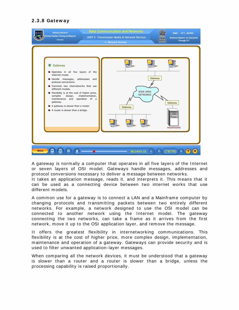
2.3.8 Gateway
A gateway is normally a computer that operates in all five layers of the Internet or seven layers of OSI model. Gateways handle messages, addresses and protocol conversions necessary to deliver a message between networks. It takes an application message, reads it, and interprets it. This means that it can be used as a connecting device between two internet works that use different models.
A common use for a gateway is to connect a LAN and a Mainframe computer by changing protocols and transmitting packets between two entirely different networks. For example, a network designed to use the OSI model can be connected to another network using the Internet model. The gateway connecting the two networks, can take a frame as it arrives from the first network, move it up to the OSI application layer, and remove the message.
It offers the greatest flexibility in internetworking communications. This flexibility is at the cost of higher price, more complex design, implementation, maintenance and operation of a gateway. Gateways can provide security and is used to filter unwanted application-layer messages.
When comparing all the network devices, it must be understood that a gateway is slower than a router and a router is slower than a bridge, unless the processing capability is raised proportionally.
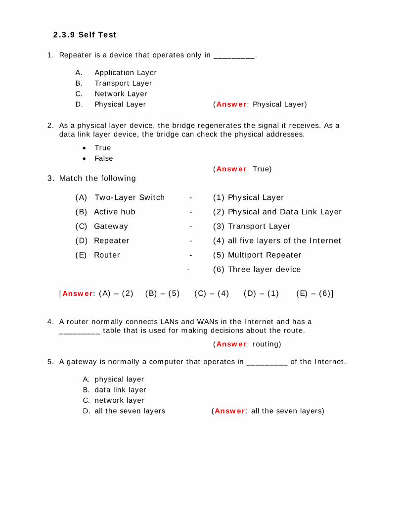
2.3.9 Self Test
1. Repeater is a device that operates only in _________.
A. Application Layer B. Transport Layer C. Network Layer D. Physical Layer (Answer: Physical Layer)
2. As a physical layer device, the bridge regenerates the signal it receives. As a
data link layer device, the bridge can check the physical addresses.
• True • False
(Answer: True) 3. Match the following
(A) Two-Layer Switch - (1) Physical Layer
(B) Active hub - (2) Physical and Data Link Layer
(C) Gateway - (3) Transport Layer
(D) Repeater - (4) all five layers of the Internet
(E) Router - (5) Multiport Repeater
- (6) Three layer device
[Answer: (A) – (2) (B) – (5) (C) – (4) (D) – (1) (E) – (6)]
4. A router normally connects LANs and WANs in the Internet and has a
_________ table that is used for making decisions about the route.
(Answer: routing)
5. A gateway is normally a computer that operates in _________ of the Internet.
A. physical layer B. data link layer C. network layer D. all the seven layers (Answer: all the seven layers)
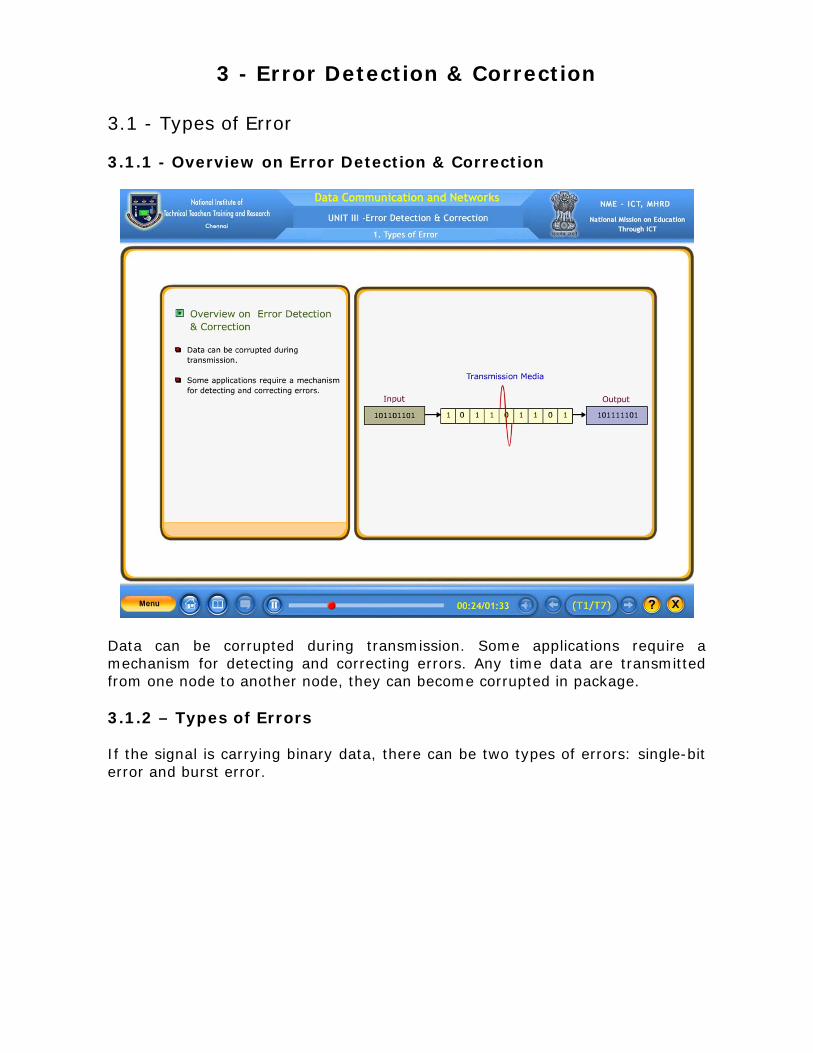
3 - Error Detection & Correction
3.1 - Types of Error 3.1.1 - Overview on Error Detection & Correction
Data can be corrupted during transmission. Some applications require a mechanism for detecting and correcting errors. Any time data are transmitted from one node to another node, they can become corrupted in package. 3.1.2 – Types of Errors If the signal is carrying binary data, there can be two types of errors: single-bit error and burst error.
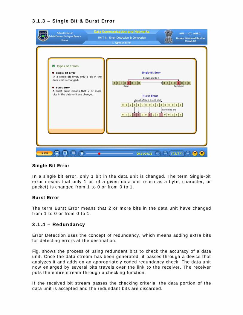
3.1.3 – Single Bit & Burst Error
Single Bit Error In a single bit error, only 1 bit in the data unit is changed. The term Single-bit error means that only 1 bit of a given data unit (such as a byte, character, or packet) is changed from 1 to 0 or from 0 to 1. Burst Error The term Burst Error means that 2 or more bits in the data unit have changed from 1 to 0 or from 0 to 1. 3.1.4 – Redundancy Error Detection uses the concept of redundancy, which means adding extra bits for detecting errors at the destination. Fig. shows the process of using redundant bits to check the accuracy of a data unit. Once the data stream has been generated, it passes through a device that analyzes it and adds on an appropriately coded redundancy check. The data unit now enlarged by several bits travels over the link to the receiver. The receiver puts the entire stream through a checking function. If the received bit stream passes the checking criteria, the data portion of the data unit is accepted and the redundant bits are discarded.

3.1.5 – Error Detection Vs Error Correction In Error Detection, Check whether any error has occurred. In Error Correction, Need to know the exact number of corrupted bits and their location in the data frame. The most common technique used for Error Detection is VRC, LRC, CRC and Checksum. The Technique called Hamming Code is used for Error Correction. 3.1.6 – Forward Error Correction Vs Retransmission
• Forward Error Correction is the process in which the receiver tries to guess the message by using redundant bits. • Correction by Retransmission is a technique in which the receiver detects the occurrence of an error and asks the sender to resend the message. • Forward Error Correction is Possible when the number of errors is small. • Resending is repeated until a message arrives that the receiver believes is error-free.
3.1.7 – Data word, Codeword and X-OR In block coding, we divide our message into blocks, each of k bits, called datawords. We add r redundant bits to each block to make the length n = k + r. The resulting n-bit blocks are called codewords. The Fig. explains that, it is important to know that it has a set of datawords, each of size k, and a set of codewords, each of size n. With k bits, we can create a combination of 2k datawords; with n bits, we can create a combination of 2n codewords. Since n>k, the number of possible codewords is larger than the number of possible data-words. The block coding process is one-to-one; the same dataword is always encoded as the same codeword. This means that we have 2n – 2k codewords that are not used. We call these codewords invalid or illegal. X-OR
If the two bits are same; the result will be 0.
If the two bits are different, the result will be 1.Resulting of XORing two patterns. Here the first bits of two binary numbers are same so the result will be 0.Next bits are different so the result will be 1 likewise it will XOR the two binary numbers.
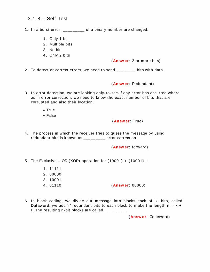
3.1.8 – Self Test
1. In a burst error, _________ of a binary number are changed.
1. Only 1 bit 2. Multiple bits 3. No bit 4. Only 2 bits
(Answer: 2 or more bits)
2. To detect or correct errors, we need to send ________ bits with data.
(Answer: Redundant) 3. In error detection, we are looking only-to-see-if any error has occurred where
as in error correction, we need to know the exact number of bits that are corrupted and also their location.
• True • False (Answer: True)
4. The process in which the receiver tries to guess the message by using redundant bits is known as _________ error correction.
(Answer: forward)
5. The Exclusive – OR (XOR) operation for (10001) + (10001) is
1. 11111 2. 00000 3. 10001 4. 01110 (Answer: 00000)
6. In block coding, we divide our message into blocks each of ‘k’ bits, called
Dataword, we add ‘r’ redundant bits to each block to make the length n = k + r. The resulting n-bit blocks are called _________.
(Answer: Codeword)

3.2 - Error Detection 3.2.1 - Overview on Error Detection
An error-detecting code can detect only the types of errors for which it is designed; other types of errors may remain undetected. Errors can be detected by the following two conditions.
1. The receiver has a list of valid codeword.
2. The original codeword has changed to an invalid one.
The sender creates codewords out of datawords by using a generator that applies the rules and procedures of encoding. Each codeword sent to the receiver may change during transmission. If the received codeword is the same as one of the valid codewords, the word is accepted; the corresponding dataword is extracted for use. If the received codeword is not valid, it is discarded. However, if the codeword is corrupted during transmission but the received word still matches a valid codeword, the error remains undetected. This type of coding can detect only single errors. Two or more errors may remain undetected.
Let us assume that k = 2 and n = 3. Table shows the list of datawords and codewords. Later, we will see how to derive a codeword from a dataword.
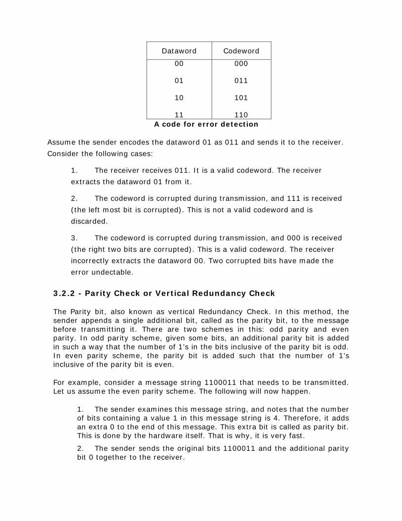
A code for error detection
Assume the sender encodes the dataword 01 as 011 and sends it to the receiver.
Consider the following cases:
1. The receiver receives 011. It is a valid codeword. The receiver
extracts the dataword 01 from it.
2. The codeword is corrupted during transmission, and 111 is received
(the left most bit is corrupted). This is not a valid codeword and is
discarded.
3. The codeword is corrupted during transmission, and 000 is received
(the right two bits are corrupted). This is a valid codeword. The receiver
incorrectly extracts the dataword 00. Two corrupted bits have made the
error undectable.
3.2.2 - Parity Check or Vertical Redundancy Check
The Parity bit, also known as vertical Redundancy Check. In this method, the sender appends a single additional bit, called as the parity bit, to the message before transmitting it. There are two schemes in this: odd parity and even parity. In odd parity scheme, given some bits, an additional parity bit is added in such a way that the number of 1’s in the bits inclusive of the parity bit is odd. In even parity scheme, the parity bit is added such that the number of 1’s inclusive of the parity bit is even.
For example, consider a message string 1100011 that needs to be transmitted. Let us assume the even parity scheme. The following will now happen.
1. The sender examines this message string, and notes that the number of bits containing a value 1 in this message string is 4. Therefore, it adds an extra 0 to the end of this message. This extra bit is called as parity bit. This is done by the hardware itself. That is why, it is very fast.
2. The sender sends the original bits 1100011 and the additional parity bit 0 together to the receiver.
Dataword Codeword
00
01
10
11
000
011
101
110
3. The receiver separates the parity bit from the original bits, and it also examines the original bits. It sees the original bits as 1100011, and notes that the number of 1’s in the message is four (i.e. even).
4. The receiver now computes the parity bit again and compares this computed parity bit with the 0 parity bit received from the sender, notes that they are equal, and accepts the bit string as correct. This is also done by hardware itself. This process is shown in figure.
In contrast, if the original message was 1010100, the number of 1’s in the message would have been three (odd), and therefore, the parity bit would have contained a 1.
There is one problem with this scheme. This scheme can only catch a single bit error. If two bits reverse, this scheme will fail. For instance, if the first two bits in the bit stream shown in figure change, we will get a stream 0000011, yielding a parity bit of 0 again, fooling us.
3.2.3 - Longitudinal Redundancy Check
Generates a parity bit from a specified string of bits on a longitudinal track. A block of bits is organized in the form of a list (as rows) in the Longitudinal Redundancy Check (LRC). Here, for instance, if we want to send 32 bits, we arrange them into a list of four rows. Then the parity bit for each column is calculated and a new row of eight bits is created. These become the parity bits for the whole block. An example of LRC is shown in Figure.
3.2.4 - Cyclic Redundancy Check
Designed to detect accidental changes to raw computer data. In Cyclic Redundancy Check (CRC), a sequence of otherwise redundant overhead bits called as CRC or CRC remainder is added to the end of the data to be transmitted. The CRC is so calculated that it can be perfectly divided by a second pre-decided number. If this division produces a zero remainder, the transmission is considered as error-free. In such a case, the incoming data is accepted by the receiver. If there is a remainder, it means that the transmission is in error and therefore, the arriving data must be rejected. At a broad level, the process is shown in figure.
Sender calculates CRC.
Sender sends data and CRC together to the receiver.
Receiver computes its own CRC using the same formula as was used by the sender on the data received.
If the two CRCs match, the receiver accepts the transmission, else rejects it.

3.2.5-Checksum
Checksum is a technique used for error detection by higher-level protocols. It is also based on the concept of redundant information.
Senders End
At the sender’s end, the checksum generator divides the data to be sent
into small segments, each segment consisting of k bits. Usually, k=16.
After this, these segments are added together by using the one’s
complement arithmetic so that the total of these segments are added in
length. This total is further complemented, and is added to the end of the
data segments is S, then the checksum is –S. This is because a
complement is taken of the sum. We can summarize these steps as shown
below
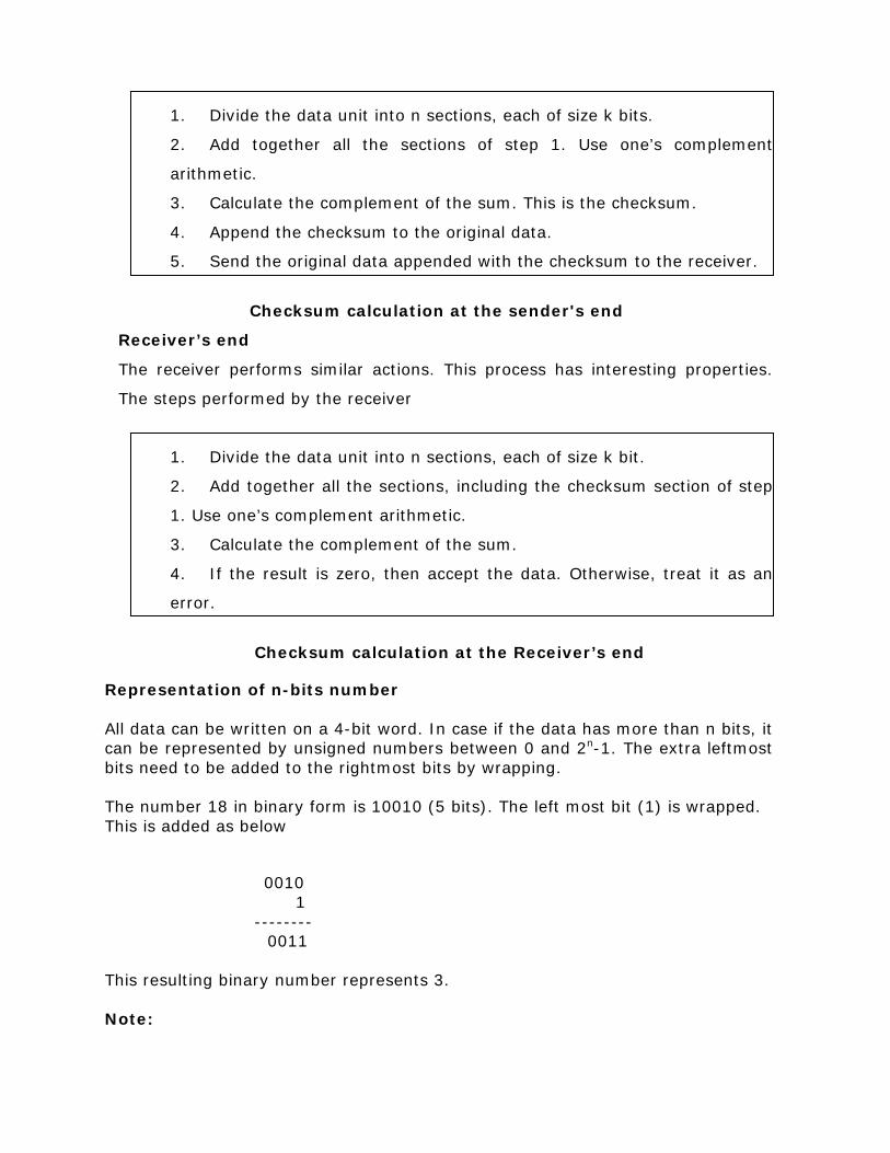
1. Divide the data unit into n sections, each of size k bits.
2. Add together all the sections of step 1. Use one’s complement
arithmetic.
3. Calculate the complement of the sum. This is the checksum.
4. Append the checksum to the original data.
5. Send the original data appended with the checksum to the receiver.
Checksum calculation at the sender's end
Receiver’s end
The receiver performs similar actions. This process has interesting properties.
The steps performed by the receiver
1. Divide the data unit into n sections, each of size k bit.
2. Add together all the sections, including the checksum section of step
1. Use one’s complement arithmetic.
3. Calculate the complement of the sum.
4. If the result is zero, then accept the data. Otherwise, treat it as an
error.
Checksum calculation at the Receiver’s end
Representation of n-bits number All data can be written on a 4-bit word. In case if the data has more than n bits, it can be represented by unsigned numbers between 0 and 2n-1. The extra leftmost bits need to be added to the rightmost bits by wrapping. The number 18 in binary form is 10010 (5 bits). The left most bit (1) is wrapped. This is added as below
0010 1 -------- 0011 This resulting binary number represents 3. Note:

If one’s complement arithmetic, a negative (signed) number can be represented by inverting all bits (changing 0s to 1s and 1s to 0s). This is same as subtracting the number from 2n-1. Suppose that the sender wants to send a 16-bit data stream as follows:
01101001 01000110
Calculate the checksum at the sender’s end.
Solution: We divide the data stream into two sections of eight bits each. We
then add them using one’s complement arithmetic.
The receiver would send a bit stream of 01101001 01000110 01010000.
Note that the first 16 bits are data bits and the last 8 bits are the checksum
bits.
Suppose that the sender has sent the following bit stream, to the receiver,
with the last 8 bits as the checksum:
01101001 01000110 01010000
Show how the receiver would verify the checksum.
Solution: we divide the data stream into two sections of eight bits each. We
then add them and the checksum bit stream using one’s complement
arithmetic.
We can see that the receiver gets 0 as the result. This proves that the data
bits were not changed during transit. The receiver can safely accept the bit
stream 01101001 01000110.

3.2.6 Self Test 1. Checksum is a technique used for error correction.
• True • False (Answer: False)
2. In Parity check method, the sender sends a single additional bit, called as the
________ bit. (Answer: Parity)
3. Match the following
(A) Parity bit - (1) Hamming code
(B) Last Error Detection Technique - (2) Vertical redundancy Check
(C) Redundant overhead bits - (3) Checksum
(D) Longitudinal Track - (4) Cyclic Redundancy Code
(E) Data words - (5) Longitudinal Redundancy
Check
- (6) Size k
[Answer: (A) – (2) (B) – (3) (C) – (4) (D) – (5) (E) – (6)] 4. CRC is normally implemented in software rather than in hardware.
• True
• False (Answer: False) 5. Process of checking errors in communication transmissions by combining vertical error checking and _________ error checking.
A. cyclic B. longitudinal C. checksum D. parity bit (Answer: longitudinal)
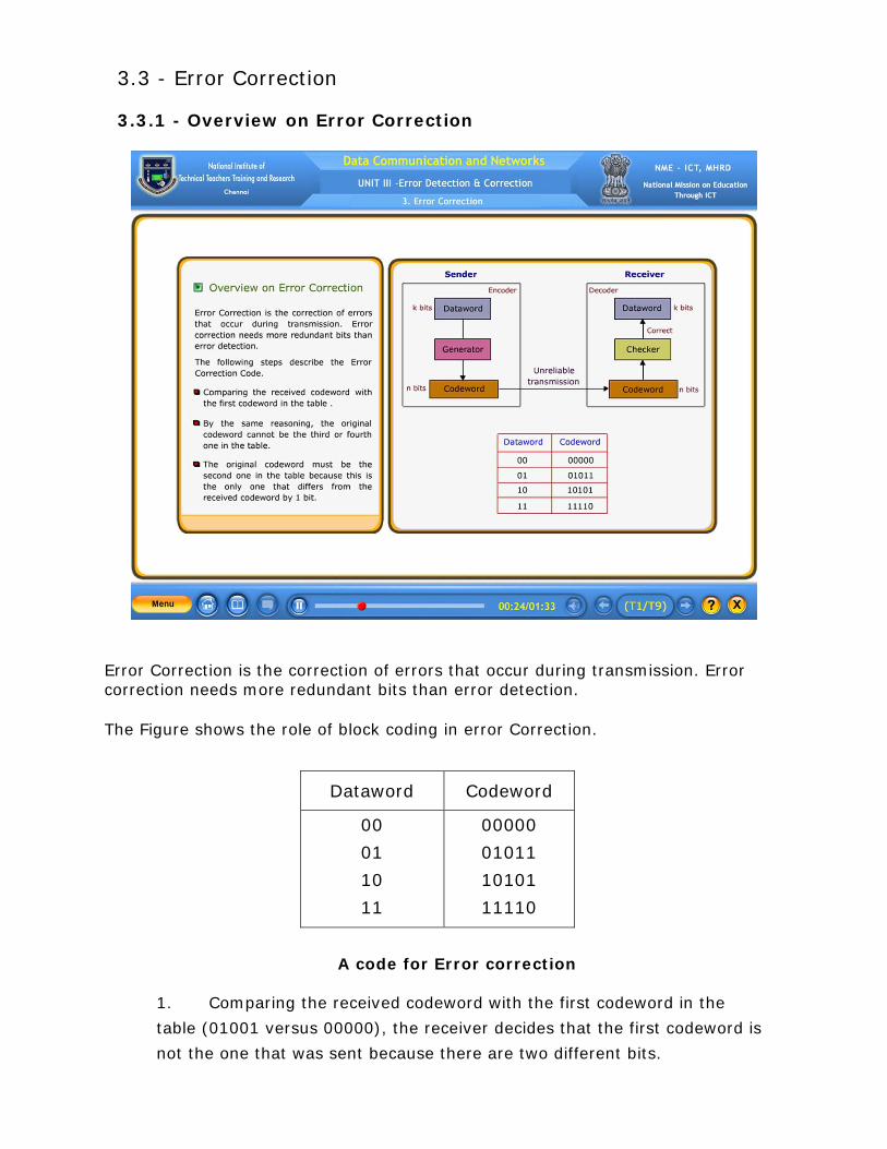
3.3 - Error Correction 3.3.1 - Overview on Error Correction
Error Correction is the correction of errors that occur during transmission. Error correction needs more redundant bits than error detection.
The Figure shows the role of block coding in error Correction.
A code for Error correction
1. Comparing the received codeword with the first codeword in the
table (01001 versus 00000), the receiver decides that the first codeword is
not the one that was sent because there are two different bits.
Dataword Codeword
00
01
10
11
00000
01011
10101
11110

2. By the same reasoning, the original codeword cannot be the third or
fourth one in the table.
3. The original codeword must be the second one in the table because
this is the only one that differs from the received codeword by 1 bit. The
receiver replaces 01001 with 01011 and consults the table to find the
dataword 01.
3.3.2 - Error Correction Using Hamming Code
A technique called as Hamming code can be used for Error Correction which is
used for data units of any size.
If we want to apply Hamming code to a 7-bit ASCII value, we need to add 4
redundant bits in the positions 1, 2, 4 & 8 (Note that all these bit positions are
power of 2).
Thus, the original value now becomes as shown in table, with the original data
bits depicted as d and the redundant bits indicated with r.
As a result, the original bit stream and the modified bit stream is shown below.

The shaded boxes show the redundant bits. We now name them as per the
position (i.e. the redundant bit in position 1 is r1).
3.3.3 - Logic behind Redundant Bits
• The Redundant bits indicate that, the VRC bits for some combination
of data bits.
• Let us name those redundant bits in positions 1, 2, 4 and 8 as r1, r2,
r4 and r8.
1. The r1 will be based on the bit positions 1, 3, 5, 7, 9 and 11.
2. The Decimal and Binary representations of the above bit
positions are shown in Table.
Step: 1. Here All the binary equivalents of the bit positions for r1 ends
with 1 (i.e., the last bit in all these is 1).
Step: 2. For r2, the second last bit of all the bit positions are 1.
Step: 3. Similarly for r3 and r4, the third and fourth bit positions from
the right would be 1. This is shown in further tables….
By pressing NEXT button.
3.3.4 - Calculating Redundant Bits
1. Using the concept of VRC, the actual calculation of the redundant bits
takes place.
2. This is a four step Process as shown below.
a) Place every bit of the original bit stream in its appropriate
position in the 11-bit segment.
b) Calculate even parity for the appropriate bit combinations (e.g.
for r1- use bit positions 3, 5, 7, 9, 11…).
c) Place the respective parity bit in a appropriate slot (i.e., Place
r1 in position in 1, r2 in position 2, r4 in position 4 and r8 in position
8.)
d) The result is the 11-bit stream containing 7-bit data and 4-bit
Hamming Code which can be sent.
The following steps show the calculation of Hamming Code.
1. Original data is placed into 11-bit segment.
2. Calculating r1 and placing its value into position 1.
3. Calculating r2 and placing its value into position 2.
4. Calculating r4 and placing its value into position 4
5. Calculating r8 and placing its value into position 8.
6. Resulting 11-bit stream to be sent to the receiver.
3.3.5 - Hardware Implementation
One of the advantages of a cyclic code is that the encoder can easily and cheaply
be implemented in hardware by using a handful of electronic devices. Also, a
hardware implementation increases the rate of check bit and syndrome bit
calculation.
Note that if the leftmost bit of the part of dividend to be used in this step is 1, the
divisor bits (d2d1d0) are 011; if the leftmost bit is 0, the divisor bits are 000. The
design provides the right choice based on the leftmost bit.
3.3.6 – Simulating of CRC Encoder
The following is the step-by-step process that can be used to simulate the division
process in hardware.
1. We assume that the remainder is originally all 0s (000 in our
example).
2. At each time click (arrival of 1 bit from an augmented dataword). We
repeat the following two actions:
o We use the leftmost bit to make a decision about the divisor
(011 or 000).
o The other two bits of the remainder and the next bit from the
augmented dataword (total of 3 bits) are XORed with the 3-bit
divisor to create the next remainder.
The following figure shows the simulator
1. Here the Augmented Dataword is 1001000.
2. The Augmented dataword as fixed in position with the divisor bits
shifting to the right, 1 bit in each step. That is the divisor is always fixed

and need to shift the bits of the augmented dataword to left (opposite
direction) to align the divisor bits to the appropriate part.
At each clock tick, shown as different times, one of the bits from the
augmented dataword is used in the XOR process.
3. In this design we have seven steps
The first 3 steps have been added here to make each step equal and to make the design for each step the same.
Steps 1, 2 and 3 push the first 3 bits to the remainder register.
Note that the values in the remainder register in steps 4, 5, 6 and 7.
Note that if the leftmost bit of the dividend to be used in these steps is 1, then the divisor bits are 011 (if the leftmost bit is 0, the divisor bits are 000).
In steps 4, 5, 6 and 7, it follows the same process like steps 1, 2, and 3 and the 7th step is the last step which having the last augmented bit.
Finally the remainder will be 110.
3.3.7 - CRC Encoder and Decoder Design
A 1 -bit shift register holds a bit for duration of one clock time. At a time click, the
shift register accepts the bit at its input port, stores the new bit, and displays it on
the output port. The content and the output remain the same until the next input
arrives. When we connect several 1-bit shift registers together, it looks as if the
contents of the register are shifting.
3.3.8 - Polynomials
A better way to understand cyclic codes and how they can be analyzed is to
represent them as polynomials.
A pattern of 0s and 1s can be represented as a polynomial with coefficients of 0
and 1. The power of each term shows the position of the bit; the coefficient shows
the value of the bit. Figure shows a binary pattern and its polynomial
representation. In the first figure, it shows how to translate a binary pattern to a
polynomial. The second figure shows how the polynomial can be shortened by
removing all terms with zero coefficients and replacing x1 by x and x0 by 1. The
figure shows on immediate benefit; a 7-bit pattern can be replaced by three
terms.
3.3.9 - Advantages of Cyclic Codes
1. Cyclic codes have a very good performance in detecting single-bit
errors, double errors, an odd number of errors and burst errors.
2. They can easily be implemented in hardware and software.
3. They are especially fast when implemented in hardware.
4. This has made cyclic codes a good candidate for many networks.

3.3.10 Self Test
1. In error correction the receiver needs to find the original ________ sent.
(Answer: codeword)
2. The Hamming distance between two words is the number of differences between corresponding bits.
• True • False (Answer: True)
3. Match the polynomial representation for the following binary patterns.
Binary Pattern Polynomial Representation
(A) 1 0 1 1 0 0 - (a) x4+x3+1
(B) 1 1 0 0 1 - (b) x6+x4+x3
(C) 0 1 0 0 1 1 - (c) x2+x
(D) 0 0 1 1 0 - (d) x5+x4+x3+x2+x+1
(E) 1 1 1 1 1 1 - (e) x5+x3+x2 - (f) x4+x+1
[Answer: (A) – (e) (B) – (a) (C) – (f) (D) – (c) (E) – (d)]
4. An 1 -bit shift register holds a bit for a duration of ____ clock time. (Answer: one)
5. In CRC Encoder, if the left most bit is 1, then the divisor bits are _______.
A. 000 B. 111 C. 100
D. 011 (Answer: 011)
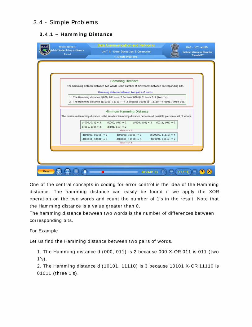
3.4 - Simple Problems 3.4.1 – Hamming Distance
One of the central concepts in coding for error control is the idea of the Hamming
distance. The hamming distance can easily be found if we apply the XOR
operation on the two words and count the number of 1’s in the result. Note that
the Hamming distance is a value greater than 0.
The hamming distance between two words is the number of differences between
corresponding bits.
For Example
Let us find the Hamming distance between two pairs of words.
1. The Hamming distance d (000, 011) is 2 because 000 X-OR 011 is 011 (two
1's).
2. The Hamming distance d (10101, 11110) is 3 because 10101 X-OR 11110 is
01011 (three 1's).

Minimum Hamming Distance
The concept of the Hamming distance is the central point in dealing with error
detection and correction codes, the measurement that is used for designing a
code is the minimum Hamming distance.
The minimum hamming distance is the smallest Hamming distance between all
possible pairs in a set of words.
For Example
1) The minimum distance of the coding scheme in Table 1- Code for Error
Detection as follows.
First find out all Hamming distances.
d (000, 011) = 2, d (000, 101) = 2 , d (000, 110) = 2 , d (011, 101) = 2,
d (011, 110) = 2, d (101, 110) = 2.
The dmin in this case is 2.
2) The minimum Hamming distance of the coding scheme in Table 2- Code for
Error Correction as follows
d (00000, 01011) = 3, d (00000, 10101) = 3, d (00000, 11110) = 4 ,
d (01011, 10101) = 4, d (01011, 11110 ) = 3, d (10101, 11110) = 3.
The dmin in this case is 3.
3.4.2 – Three Parameters
Any coding scheme that needs to have at least three parameters: the codeword
size n, the dataword size k, and the minimum Hamming distance dmin
Hamming Distance and Error
Hamming distance between the sent and received codewords is the number of bits
affected by the error. In other words, the Hamming distance between the received
codeword and the sent codeword is the number of bits that are corrupted during
transmission. For example, if the codeword 00000 is sent and 01101 is received,
3 bits are in error and the Hamming distance between the two is d(00000,01101)
= 3.
Minimum Distance for Error detection
To guarantee the detection of up to s errors in all cases, the minimum Hamming
distance in a block code must be dmin = s+1.
Minimum Distance for Error Correction
To guarantee correction of up to t errors in all cases, the minimum Hamming
distance in a block code must be dmin = 2t+1.

3.4.3 - Simple Problems (Check Sum)
Checksum is the last Error detection method which is used in the
Internet by several protocols although not at the Data link layer.
Like linear and cyclic codes, the checksum is based on the concept of redundancy.
The concept of the checksum is not difficult. Let us illustrate it with examples.
Example 1
How can we represent the number 21 in one’s complement arithmetic using only
four bits?
Solution:
The number 21 in binary is 10101. We can wrap the leftmost bit and add it to the
four rightmost bits. We have (0101 + 1) = 0110 or 6.
Example 2
The figure shows the process at the sender and at the receiver.
The sender initializes the checksum to 0 and adds all data items and
the checksum (the checksum is considered as one data item and is shown
in color). The result is 36.
However, 36 cannot be expressed in 4 bits. The extra two bits are
wrapped and added with the sum to create the wrapped sum value 6.
In the figure, we have shown the details in binary. The sum is then
complemented, resulting in the checksum value 9 (15-6=9). The sender
now sends six data items to the receiver including the checksum 9.
The receiver follows the same procedure wrapped and becomes 15.
The wrapped sum is complemented and becomes 0. Since the value of the
checksum is 0, this means that the data is not corrupted. The receiver
drops the checksum and keeps the other data items. If the checksum is not
zero, the entire packet is dropped.
3.4.4 Self Test
1. The representation of the number 42 in one’s complement arithmetic using
only four bits is 1100 or 12
• True • False (Answer: True)
2. Match the Hamming Distance between two pairs of words.
Two-pairs of words dmin
(A) d (001, 000) (a) 4 (B) d (01101, 10000) (b) 6
(C) d (111, 100) (c) 3 (D) d (1001, 0110) (d) 1 (E) d (100100, 011011) (e) 7
(f) 2
[Answer: (A) – (d) (B) – (c) (C) – (f) (D) – (a) (E) – (b)]
3. The correction of up to ‘t’ errors in all cases, the minimum Hamming distance (dmin) in a block code must be ___________
(Answer: dmin = 2t+1) 4. If the Sum, Wrapped Sum and Checksum at the Sender site is 40, 10 and 5
then what will be the Sum, Wrapped Sum and checksum at the Receiver site
A. 45, 0 and 15 B. 45, 15 and 0 C. 15 and 0 D. 15, 45 and 0 (Answer: 45, 15 and 0)
5. Hamming distance between the sent and received codewords is the number of
bits affected by the ________. (Answer: error)

4 - Flow and Error Control & LAN Protocols 4.1 - Concept of Framing 4.1.1 - Data link control The two main functions of the data link layer are data link control and media access control. Data link control, deals with the design and procedures for communication between two adjacent nodes. Node-to-node communication. Framing, flow and error control, and software implemented protocols. Packing bits into frames.
4.1.2 - Introduction to Framing
Framing: Separates a message from one source to a destination, by adding a sender address and a destination. Fixed size framing: There is no need for defining the boundaries of the frame. The size itself can be used as a delimiter. Variable size framing: Need a way to define the end of the frame and the beginning of the next. Prevalent in local-area networks. Two approaches were used for this purpose:
1. Character - oriented protocols 2. Bit - oriented protocols

4.1.3 - Character oriented protocols
Data to be carried are 8-bit character from a coding system such as ASCII.
The header which normally carries the source and destination addresses and other control information, and the trailer, which carries error detection or error correction redundant bits, are also multiples of 8 bits.
The flag could be selected to be any character not used for text communication.
Any pattern used for the flag could also be part of the information.
The receiver thinks it has reached the end of the frame.

4.1.4 – Cop (Byte stuffing & Unstuffing)
When data and flag has same pattern, problem occurs. Byte stuffing is the process of adding 1 extra byte whenever there is a flag or escape character in the text.
Escape Character (ESC) has a predefined bit pattern and treated not as a delimiting flag.
Byte stuffing is the process of adding 1 extra byte whenever there is a flag or escape character in the text.
4.1.5 - Bit oriented protocols Whenever the flag pattern appears in the data, the receiver has to be informed that this is not the end of the frame.
This is done by stuffing 1 single bit to prevent the pattern from looking like a flag. The strategy is called Bit Stuffing.
Bit stuffing is the process of adding one extra 0 whenever five consecutive 1s follow a 0 in the data, so that the receiver does not mistake the pattern 0111110 for a flag.
The animation shows bit stuffing at the sender and bit removal at the receiver. Note that even if 0 appears after 5 1s, still 0 is stuffed. The 0 will be removed by the receiver. The real flag is not stuffed by the sender and is recognized by the receiver. 4.1.6 - Bop (Bit stuffing & Unstuffing)
Bit stuffing is the process of adding one extra 0 whenever five consecutive 1s follow a 0 in the data, so that the receiver does not mistake the pattern 0111110 for a flag.
The animation shows bit stuffing at the sender and bit removal at the receiver. Note that even if 0 appears after 5 1s, still 0 is stuffed.
The 0 will be removed by the receiver. The real flag is not stuffed by the sender and is recognized by the receiver.
4.1.7 - Flow and Error Control The Flow control and Error control are the responsibilities of the Data Link Layer and these functions are known as Data link control.
Flow Control Refers to a set of procedures used to restrict the amount of data that the sender can send before waiting for acknowledgment.
Error Control Error control is the retransmission of data and is based on Automatic Repeat Request.
Automatic Repeat Request (ARQ) Informs about lost or damaged frames & coordinates retransmission of those frames.

4.1.8 Self Test
1. Data link control deals with the design and procedures for__________ Communication.
A. node-to-node B. host-to-host C. Process-to-process D. Server-to-server (Answer: node-to-node)
2. Framing in the data link layer separates a message from one source to a destination or from other messages to other destination.
• True • False (Answer: True)
3. In fixed size framing, there is no need for defining the boundaries of the frames; the size itself can be used as a __________. (Answer: delimiter) 4. In a character-oriented protocol, data to be carried are ____________
character from a system such as ASCII.
A. 16-bit B. 32-bit C. 8-bit D. 64 bit (Answer: 8-bit)
5. For both error detection and error correction error __________ is used. (Answer: control)
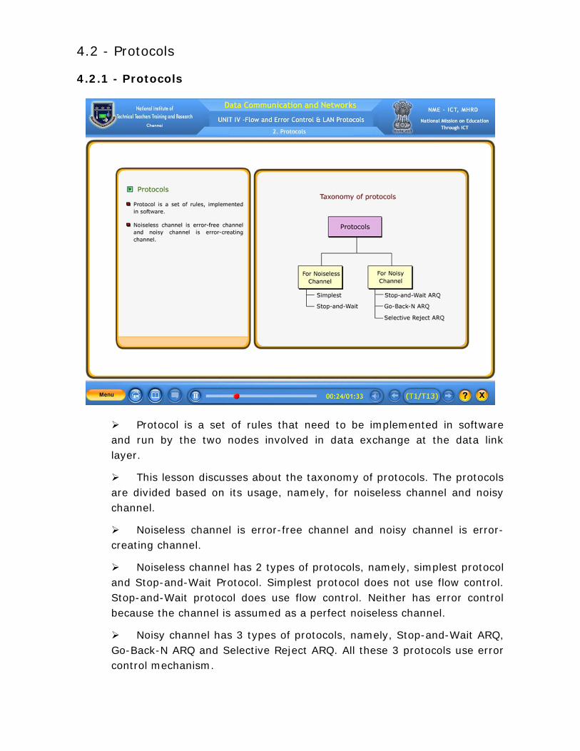
4.2 - Protocols 4.2.1 - Protocols
Protocol is a set of rules that need to be implemented in software and run by the two nodes involved in data exchange at the data link layer.
This lesson discusses about the taxonomy of protocols. The protocols are divided based on its usage, namely, for noiseless channel and noisy channel.
Noiseless channel is error-free channel and noisy channel is error-creating channel.
Noiseless channel has 2 types of protocols, namely, simplest protocol and Stop-and-Wait Protocol. Simplest protocol does not use flow control. Stop-and-Wait protocol does use flow control. Neither has error control because the channel is assumed as a perfect noiseless channel.
Noisy channel has 3 types of protocols, namely, Stop-and-Wait ARQ, Go-Back-N ARQ and Selective Reject ARQ. All these 3 protocols use error control mechanism.

4.2.2 - Simplest protocol (Design) Simplest protocol has no Flow control and Error control mechanism. The data link layer at the sender site gets data from its network layer, then makes a frame out of the data, and sends it. It is unidirectional protocol in which data frames are traveling in only one direction, from the sender to receiver.
The data link layer at the receiver site receives a frame from its physical layer, then extracts data from the frame, and delivers the data to its network layer.
The procedures used by both data link layers have to be elaborated.
Simplest protocol assumes that the processing time of the receiver is small and negligible.
If the protocol is implemented as a procedure, we need to introduce protocol. The procedure at the sender site is constantly running; there is no action until there is a request from the network layer.
The procedure at the receiver site is also constantly running, but there is no action until notification from the physical layer arrives .Both procedures are constantly running because they do not know when the corresponding events will occur. 4.2.3 - Simplest protocol (Flow Diagram)
It is very simple. The sender sends a sequence of frames without even thinking about the receiver. To send three frames, three events occur at the sender site and three events at the receiver site. The height of the box defines the transmission time difference between the first bit and the last bit in the frame. 4.2.4 - Stop and wait protocol (Design) If data frames arrive at the receiver site faster than they can be processed, the frames must be stored until their use. Normally, the receiver does not have enough storage Space, especially if it is receiving data from many sources. This may result in either the discarding of frames or denial of service. To prevent the receiver from becoming overwhelmed with frames, we somehow need to tell the sender to slow down. There must be feedback from the receiver to the sender.

Stop-and-wait protocol because the sender sends one frame, stops until it receives confirmation from the receiver (okay to go ahead), and then sends the next frame. We still have unidirectional communication for data frames but auxiliary ACK frames (simple tokens of acknowledgment) travel from the other direction. We add flow control to, our previous protocols
At any time, there is either one data frame on the forward channel or one AC frame on the reverse channel. We therefore need a half duplex link.
4.2.5 - Stop and wait protocol (Flow Diagram)
In Stop-and-wait Protocol, the sender sends one frame, stops until it receives confirmation from the receiver, and then sends the next frame. Flow Diagram for Example
1. The following figure shows the example of communication using Stop-
and-Wait Protocol.
2. The sender sends one frame and waits for feedback from the receiver.
3. When the ACK arrives, the sender sends the next frame.
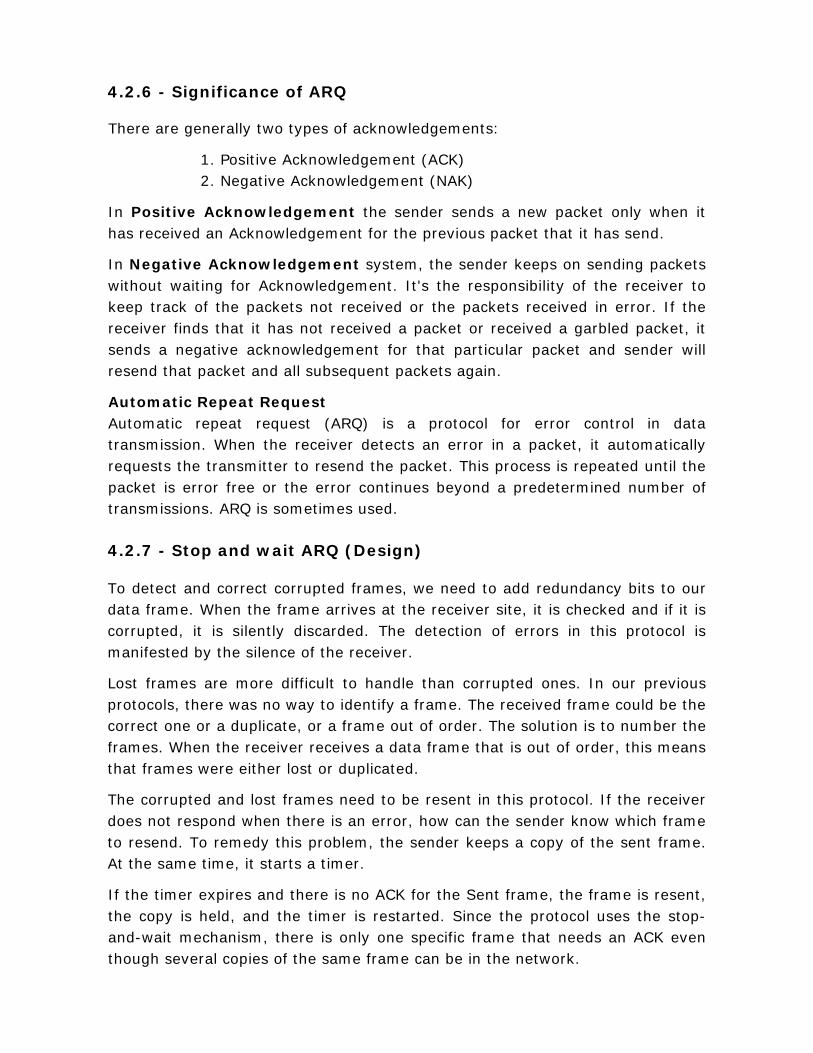
4.2.6 - Significance of ARQ There are generally two types of acknowledgements:
1. Positive Acknowledgement (ACK) 2. Negative Acknowledgement (NAK)
In Positive Acknowledgement the sender sends a new packet only when it has received an Acknowledgement for the previous packet that it has send.
In Negative Acknowledgement system, the sender keeps on sending packets without waiting for Acknowledgement. It's the responsibility of the receiver to keep track of the packets not received or the packets received in error. If the receiver finds that it has not received a packet or received a garbled packet, it sends a negative acknowledgement for that particular packet and sender will resend that packet and all subsequent packets again.
Automatic Repeat Request Automatic repeat request (ARQ) is a protocol for error control in data transmission. When the receiver detects an error in a packet, it automatically requests the transmitter to resend the packet. This process is repeated until the packet is error free or the error continues beyond a predetermined number of transmissions. ARQ is sometimes used.
4.2.7 - Stop and wait ARQ (Design) To detect and correct corrupted frames, we need to add redundancy bits to our data frame. When the frame arrives at the receiver site, it is checked and if it is corrupted, it is silently discarded. The detection of errors in this protocol is manifested by the silence of the receiver.
Lost frames are more difficult to handle than corrupted ones. In our previous protocols, there was no way to identify a frame. The received frame could be the correct one or a duplicate, or a frame out of order. The solution is to number the frames. When the receiver receives a data frame that is out of order, this means that frames were either lost or duplicated.
The corrupted and lost frames need to be resent in this protocol. If the receiver does not respond when there is an error, how can the sender know which frame to resend. To remedy this problem, the sender keeps a copy of the sent frame. At the same time, it starts a timer.
If the timer expires and there is no ACK for the Sent frame, the frame is resent, the copy is held, and the timer is restarted. Since the protocol uses the stop-and-wait mechanism, there is only one specific frame that needs an ACK even though several copies of the same frame can be in the network.
1. Error Correction in stop-and-wait ARQ is done by keeping a copy of the sent frame and retransmitting of the frame when the timer expires.
2. In stop-and-wait ARQ, we use sequence numbers to number the frames. The sequence numbers are based on modulo-2 arithmetic.
3. In stop-and-wait ARQ, the acknowledgement number always announces in modulo-2 arithmetic the sequence number of the next frame expected.
4.2.8 - Stop and Wait ARQ (Flow Diagram) Frame 0 is sent and acknowledged. Frame 1 is lost and resent after the time-out.
The resent frame 1 is acknowledged and the timer stops. Frame 0 is sent and acknowledged, but the acknowledgment is lost.
The sender has no idea if the frame or the acknowledgement is lost, so after the time-out, t resends frame 0, which is acknowledged.
4.2.9 - Go-back-N ARQ (Send window)

The send window is an imaginary box covering the sequence numbers of the data frames which can be in transit. In each window position, some of these sequence number define the frames that have been sent; others define those that can be sent. The maximum size of the window is 2m -1 for reasons that we discuss later.
Go-Back-N Protocol can send several frames before receiving acknowledgments.
In Go-Back-N Protocol, the sequence numbers are modulo 2m where m is the size of the sequence number field in bits.
The Send window is an abstract concept defining an imaginary box
of size 2m – 1 with three variables: Sf, Sn, and Ssize.
The send window can slide one or more slots when a valid acknowledgment arrives.
4.2.10 - Go-back-N ARQ (Receive window)
The receive window makes sure that the correct data frames are received and that the correct acknowledgement are sent. The size of the receive window is always 1.
The receiver is always looking for the arrival of a specific frame. Any frame arriving out of order is discarded and needs to be resent.
The receive window is an abstract concept defining an imaginary box of size 1 with one single variable Rn.
The window slides when a correct frame has arrived; sliding occurs one slot at a time.
4.2.11 - Go-back-N ARQ (Design) In the design of Go-Back-N-ARQ, multiple frames can be in transit in the forward direction, and multiple acknowledgments in the reverse direction.
The idea is similar to Stop-and-Wait ARQ; the difference is that the send window allows us to have as many frames in transition as there are slots in the send window.
To improve the efficiency of transmission (filling the pipe), multiple frames must be in transition while waiting for acknowledgment. In other words, we need to let more than one frame be outstanding to keep the channel busy while the sender is waiting for acknowledgement.
The first is called Go-Back-N Automatic Repeat Request (the rationale for the name will become clear later). In this protocol we can send several frames
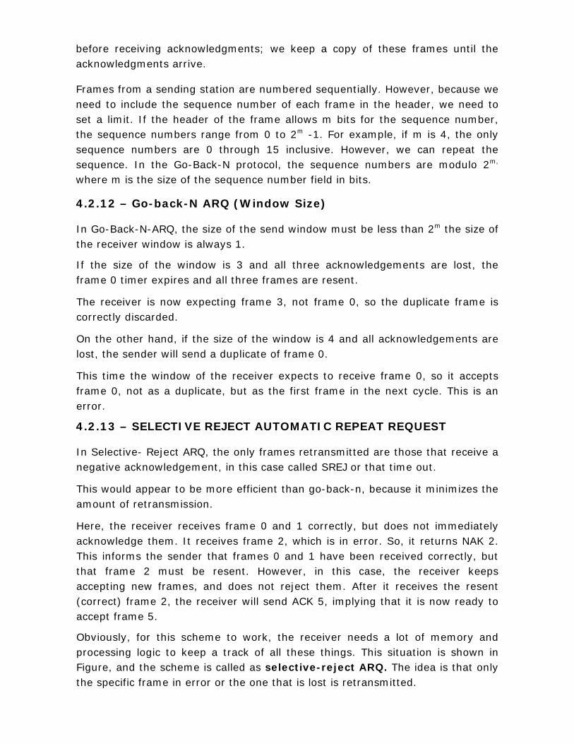
before receiving acknowledgments; we keep a copy of these frames until the acknowledgments arrive.
Frames from a sending station are numbered sequentially. However, because we need to include the sequence number of each frame in the header, we need to set a limit. If the header of the frame allows m bits for the sequence number, the sequence numbers range from 0 to 2m -1. For example, if m is 4, the only sequence numbers are 0 through 15 inclusive. However, we can repeat the sequence. In the Go-Back-N protocol, the sequence numbers are modulo 2m, where m is the size of the sequence number field in bits.
4.2.12 – Go-back-N ARQ (Window Size) In Go-Back-N-ARQ, the size of the send window must be less than 2m the size of the receiver window is always 1.
If the size of the window is 3 and all three acknowledgements are lost, the frame 0 timer expires and all three frames are resent.
The receiver is now expecting frame 3, not frame 0, so the duplicate frame is correctly discarded.
On the other hand, if the size of the window is 4 and all acknowledgements are lost, the sender will send a duplicate of frame 0.
This time the window of the receiver expects to receive frame 0, so it accepts frame 0, not as a duplicate, but as the first frame in the next cycle. This is an error.
4.2.13 – SELECTIVE REJECT AUTOMATIC REPEAT REQUEST In Selective- Reject ARQ, the only frames retransmitted are those that receive a negative acknowledgement, in this case called SREJ or that time out.
This would appear to be more efficient than go-back-n, because it minimizes the amount of retransmission.
Here, the receiver receives frame 0 and 1 correctly, but does not immediately acknowledge them. It receives frame 2, which is in error. So, it returns NAK 2. This informs the sender that frames 0 and 1 have been received correctly, but that frame 2 must be resent. However, in this case, the receiver keeps accepting new frames, and does not reject them. After it receives the resent (correct) frame 2, the receiver will send ACK 5, implying that it is now ready to accept frame 5.
Obviously, for this scheme to work, the receiver needs a lot of memory and processing logic to keep a track of all these things. This situation is shown in Figure, and the scheme is called as selective-reject ARQ. The idea is that only the specific frame in error or the one that is lost is retransmitted.
4.2.14 Self Test
1. For simplest and stop-and-wait protocol, the __________ channel can be
Used.
A. Noisy B. noiseless C. Flow control D. ARQ (Answer: noiseless)
2. Data communication requires at least two devices working together, one to send and the other to acknowledge.
• True • False (Answer: False)
3. The sender sends one frame, stops until it receives confirmation from the
receiver, and then sends the next frame. This happens in
A. Simplest protocol B. stop-and-wait protocol C. stop-and-wait-ARQ D. protocol (Answer: stop-and-wait protocol)
4. Error correction in stop-and-wait ARQ is done by keeping a copy of the sent frame and retransmitting the frame when the timer expires.
• True • False (Answer: True)
5. The abstract concept defining the range of sequence number that is the
concern of the sender and receiver is __________ window. (Answer: sliding window) 6. Match the following
(A) Noisy channel - (a) protocol for error control
(B) Stop-and-wait ARQ - (b) abstract class
(C) Send window - (c) error-creating channel
(D) Simplest protocol - (d) Error control mechanism
(E) Automatic repeat request - (e) Unidirectional
- (f) Imaginary box
[Answer: (A) – (c) (B) – (d) (C) - (f) (D) – (e) (E) – (a) ]
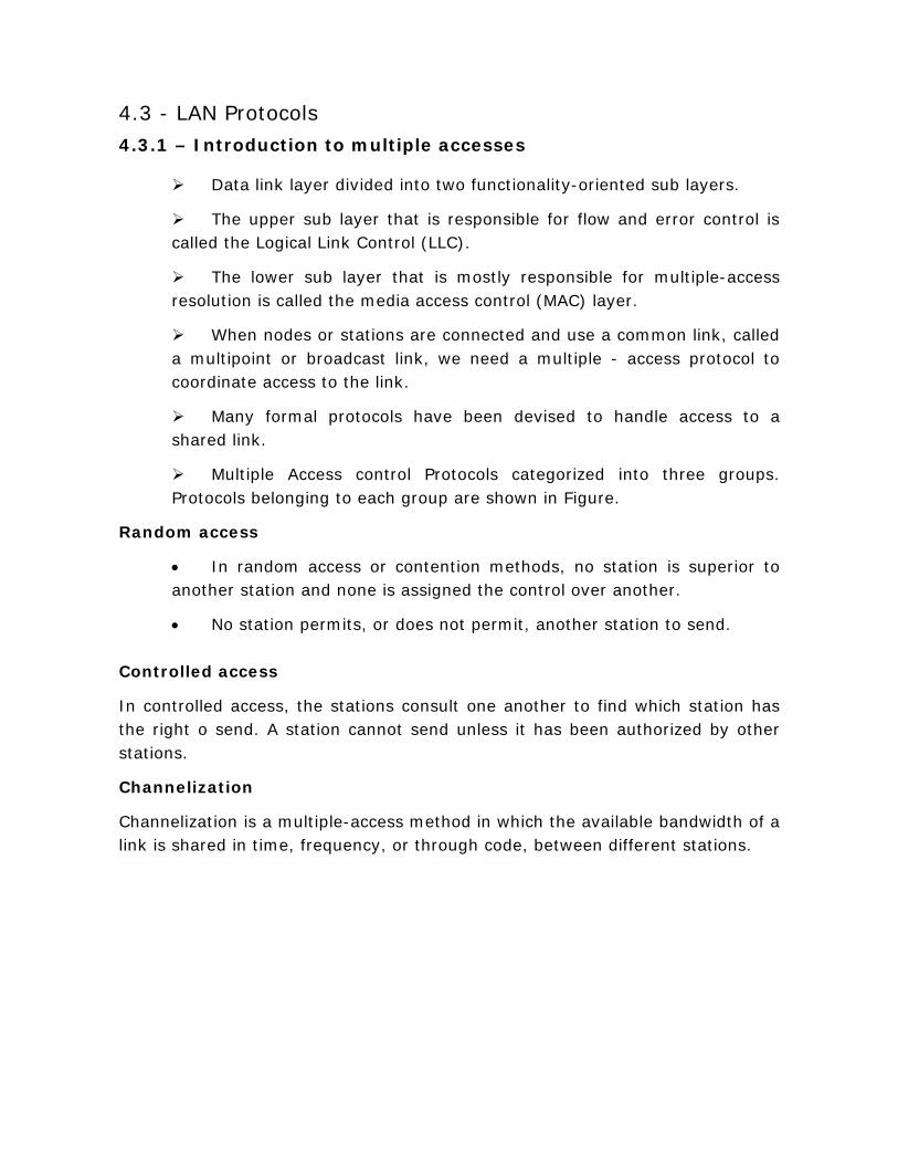
4.3 - LAN Protocols 4.3.1 – Introduction to multiple accesses
Data link layer divided into two functionality-oriented sub layers.
The upper sub layer that is responsible for flow and error control is called the Logical Link Control (LLC).
The lower sub layer that is mostly responsible for multiple-access resolution is called the media access control (MAC) layer.
When nodes or stations are connected and use a common link, called a multipoint or broadcast link, we need a multiple - access protocol to coordinate access to the link.
Many formal protocols have been devised to handle access to a shared link.
Multiple Access control Protocols categorized into three groups. Protocols belonging to each group are shown in Figure.
Random access
• In random access or contention methods, no station is superior to another station and none is assigned the control over another.
• No station permits, or does not permit, another station to send. Controlled access
In controlled access, the stations consult one another to find which station has the right o send. A station cannot send unless it has been authorized by other stations.
Channelization
Channelization is a multiple-access method in which the available bandwidth of a link is shared in time, frequency, or through code, between different stations.

4.3.2 – Carrier sense multiple access
Carrier sense Multiple Access (CSMA) is based on the principle, “sense before
transmit” or “listen before talk.
CSMA can reduce the possibility of collision, but it cannot eliminate it.
The possibility of collision still exists because of propagation delay; when a
station sends a frame, it still takes time (although very short) for the first bit to
reach every station and for every station to scene it.
At time t1, station B senses the medium and finds it idle because, at this time,
the first bits from station B have not reached station c. station c also sends a
frame. The two signals collide and both frames are destroyed.
4.3.3 – Carrier sense multiple access with collision detection
In this method, a station monitors the medium after it sends a frame to see if the transmission was successful.
The first bits transmitted by the two stations involved in the collision. Although each station continues to send bits in the frame until it detects the collision.
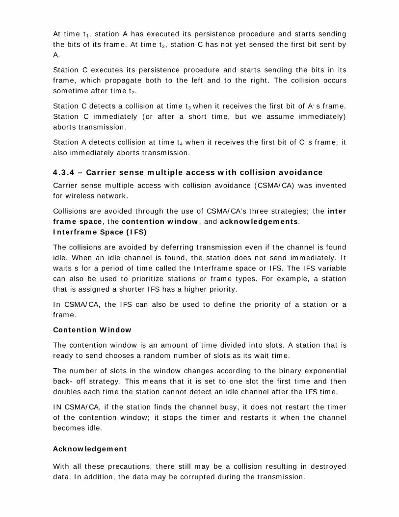
At time t1, station A has executed its persistence procedure and starts sending the bits of its frame. At time t2, station C has not yet sensed the first bit sent by A.
Station C executes its persistence procedure and starts sending the bits in its frame, which propagate both to the left and to the right. The collision occurs sometime after time t2.
Station C detects a collision at time t3 when it receives the first bit of A, s frame. Station C immediately (or after a short time, but we assume immediately) aborts transmission.
Station A detects collision at time t4 when it receives the first bit of C, s frame; it also immediately aborts transmission. 4.3.4 – Carrier sense multiple access with collision avoidance
Carrier sense multiple access with collision avoidance (CSMA/CA) was invented for wireless network.
Collisions are avoided through the use of CSMA/CA’s three strategies; the inter frame space, the contention window, and acknowledgements. Interframe Space (IFS)
The collisions are avoided by deferring transmission even if the channel is found idle. When an idle channel is found, the station does not send immediately. It waits s for a period of time called the Interframe space or IFS. The IFS variable can also be used to prioritize stations or frame types. For example, a station that is assigned a shorter IFS has a higher priority.
In CSMA/CA, the IFS can also be used to define the priority of a station or a frame.
Contention Window
The contention window is an amount of time divided into slots. A station that is ready to send chooses a random number of slots as its wait time.
The number of slots in the window changes according to the binary exponential back- off strategy. This means that it is set to one slot the first time and then doubles each time the station cannot detect an idle channel after the IFS time.
IN CSMA/CA, if the station finds the channel busy, it does not restart the timer of the contention window; it stops the timer and restarts it when the channel becomes idle. Acknowledgement With all these precautions, there still may be a collision resulting in destroyed data. In addition, the data may be corrupted during the transmission.

The positive acknowledgement and the timer-out timer can help guarantee that the receiver has received the frame. 4.3.5 - Token Passing
In the Token Passing method, the stations in a network are organized in a logical ring i.e. for each station there is a predecessor and a successor.
The Predecessor is the station which is logically before the station in the ring.
The Successor is the station which is after the station in the ring.
In a token-passing network, stations do not have to be physically connected in a ring.
The ring can be a logical one.
In the physical ring topology, when a station sends the token to its successor, the token cannot be seen by other stations; the successor is the next one in line.
This means that the token does no have to have the address of the next successor.

The dual ring topology uses a second ring which operates in the reverse direction compared with the main ring.
The second ring is for emergencies only (such as a spare tire for a car).
If one of the links in the main ring fails, the system automatically combines the two rings to form a temporary ring.
After the failed link is restored, the auxiliary ring becomes idle again.
In the bus ring topology, also called a token bus, the stations are connected to a single called a bus.
When a station has finished sending its data, it releases the token and inserts the address of the token.
Only the station with the address matching the destination address of the token gets the token to access the shared media.
In a star topology, the physical topology is a star. There is a hub, however, that acts as the connecter.
The wiring inside the hub makes the ring; the stations are connected to this ring through the two wire connections.
This topology makes the network less prone to failure because if a link goes down, it will be bypassed by the hub and the rest of the stations can operate.
Also adding and removing stations from the ring is easier.
4.3.6 Self Test
1. For wireless network, __________ was invented.
A. CSMA/CD B. CSMA C. CSMA/CA D. ALOHA (Answer: CSMA/CA)
2. The successor is the station which is logically before the station in the ring; the predecessor is the station which is after the station in the ring.
• True • False (Answer: False)
3. CSMA can reduce the possibility of __________, but it cannot eliminate it.
(Answer: collision)
4. Match the following
(A) CSMA - (a) Physical topology is a star
(B) Bus ring - (b) Successor
(C) CSMA/CA - (c) Reduce the possibility of collision
(D) Star ring - (d) Connected to a single cable
(E) Physical ring - (e) Carrier sense multiple access with collision
detection
- (f) The inter frame space
[Answer: (A) – (c) (B) – (d) (C) – (f) (D) – (a) (E) – (b)]
5. Channelization is a multiple - access method in which the available bandwidth of a link is shared in time, frequency, or through code, between different stations.
• True • False
(Answer: True)
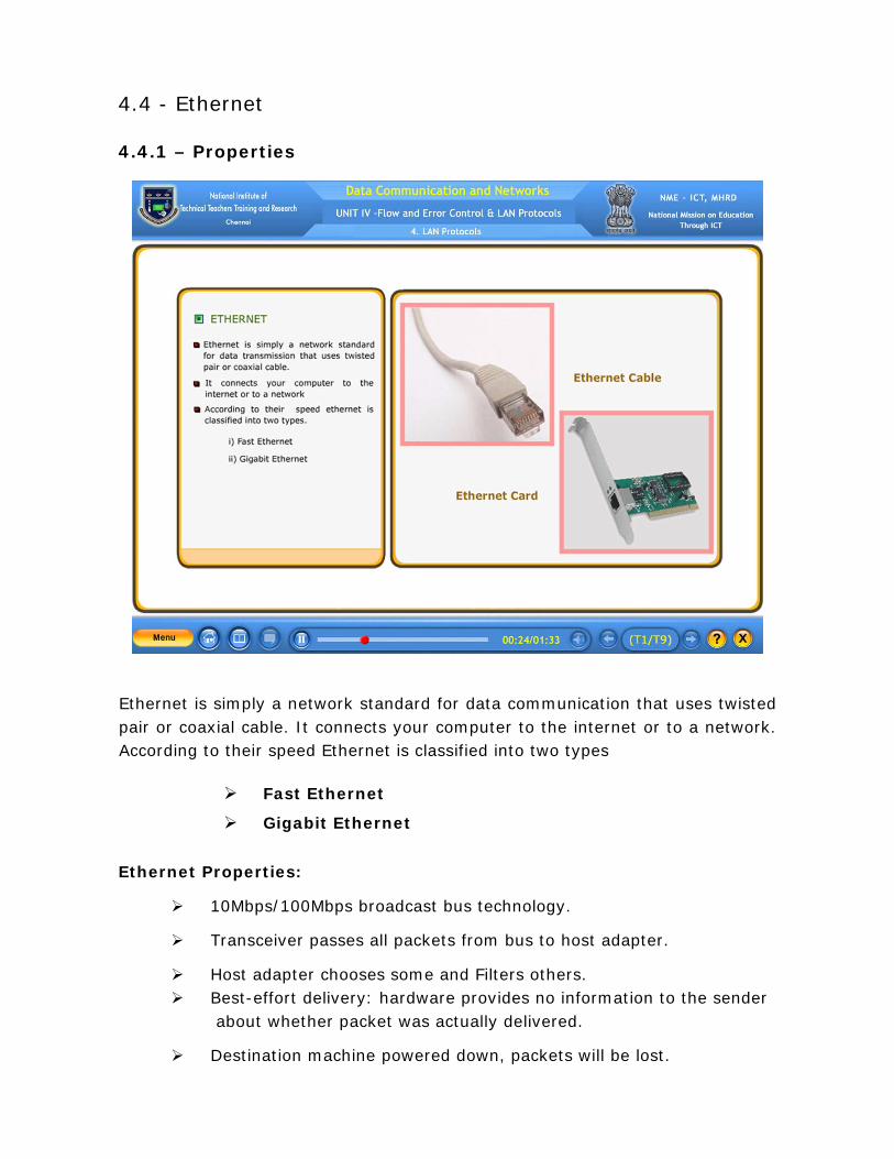
4.4 - Ethernet 4.4.1 – Properties
Ethernet is simply a network standard for data communication that uses twisted pair or coaxial cable. It connects your computer to the internet or to a network. According to their speed Ethernet is classified into two types
Fast Ethernet
Gigabit Ethernet
Ethernet Properties:
10Mbps/100Mbps broadcast bus technology.
Transceiver passes all packets from bus to host adapter.
Host adapter chooses some and Filters others. Best-effort delivery: hardware provides no information to the sender about whether packet was actually delivered.
Destination machine powered down, packets will be lost.

TCP/IP protocols accommodate best-effort delivery.
4.4.2 – Fast Ethernet (Introduction)
Fast Ethernet was designed to compete with LAN protocols such as FDDI or fiber channel. The goals of Fast Ethernet as follows:
Upgrade the data rate to 100 mbps.
Make it compatible with Standards Ethernet
Keep the same 48-bit address
Keep the same frame format
Keep the same minimum and maximum frame length
4.4.3 – Fast Ethernet (Topologies)
Fast Ethernet is designed to connect two or more stations together. It supports two types of topologies
1. Point-to-point 2. Star

Point-to-point topology If there are only two stations, they can be connected using point-to-point topology Star topology Three or more stations need to be connected in a star topology with a hub or a switch at the center. 4.4.4 – Fast Ethernet (Implementation) Fast Ethernet implementation at the physical layer can be categorized as either two-wire or four-wire.
The two-wire implementation can be either category 5 UTP (100Base-TX) or fiber-optic cable (100Base-FX). The four-wire implementation is designed only for category 3 UTP (100Base-T4) as shown in the figure. 4.4.5 – Fast Ethernet (Encoding)
100Base-TX uses two pairs of twisted-pair cable (either category 5 UTP or STP).
For this implementation, MLT-3 scheme was selected since it has good bandwidth performance. However, since MLT-3 is not a self-synchronous line coding scheme, 4B/5B block coding is used to provide bit synchronization by preventing the occurrence of a long sequence of 0s and 1s.
This creates a data rate of 125 Mbps, which is fed into MLT-3 for encoding.
100Base-FX uses two pairs of fiber-optic cables. Optical fiber can easily handle high bandwidth requirements by using simple encoding schemes. The designers of 100Base-FX selected the NRZ-I encoding scheme for this implementation. However, NRZ-I has a bit synchronization problem for long sequences of 0s (or 1s,based on the encoding.
To overcome this problem, the designers used 4B/5B block encoding as we described for 100Base-TX. The block encoding increases the bit rate from 100 to 125 Mbps, which can easily be handled by fiber-optic cable.
A new standard, called 100Base-T4, was designed to use category 3 or higher UTP.
The implementation uses four pairs of UTP for transmitting 100 Mbps.
Encoding /decoding in 100Base-T4 is more complicated. As this implementation uses category 3 UTP, each twisted-pair cannot easily handle more than 25 Mbaud. In this design, one pair switches between sending and receiving. Three pairs of UTP category 3, however, can handle only 75 Mbaud (25 Mbaud) each. We need to use an encoding scheme that converts 100 Mbps to a 75 Mbaud signal and 8B/6T satisfies this requirement.
In 8B/6T, eight data elements are encoded as six signal elements. This means that 100 Mbps uses only (6/8)*100 Mbps, or 75 Mbaud.
4.4.6 – Gigabit Ethernet (Introduction) The need for an even higher data rate resulted in the design in the design of Gigabit Ethernet Protocol The goals of Gigabit Ethernet as follows:
upgrade the data rate to 1 Gbps
Make it compatible with Standard or Fast Ethernet
Keep the same 48-bit address
Keep the same frame format
Keep the same minimum and maximum frame lengths
To support auto negotiation as defined in Fast Ethernet 4.4.7 – Gigabit Ethernet (Topologies) It supports four types of topologies
Point-to-point
Star
Two star
Hierarchy of stars Point-to-point topology Gigabit Ethernet is designed to connect two or more stations together. If there are only two stations, they can be connected point-to-point.

Star Topology Three or more stations need to be connected in a star topology with a hub or a switch at the center.
Two Stars Topology Another possible configuration is to connect several star topologies or let a star topology be part of another as shown in the figure.
Hierarchy of Stars Topology Another possible configuration is to connect several star topologies or let a star topology be part of another as shown in the figure. 4.4.8 – Gigabit Ethernet (Implementation)
Gigabit Ethernet can be categorized as either a two-wire or a four-wire implementation.
The two wire implementation use fiber-optic cable
The four-wire version uses category 5 twisted-pair cable.
100Base-T was designed in response to those users who had already installed this wiring for other purposes such as fast Ethernet or telephone services.
4.4.9 – Gigabit Ethernet (Encoding)
Two-wire implementations use an NRZ scheme, but NRZ does not self-synchronize properly. To synchronize bits, particularly at this high data rate, 8B/10B block encoding is used.
The block encoding prevents long sequences of 0s or 1s in the stream, but the resulting stream is 1.25 Gbps. Note that in this implementation, one wire (fiber or STP) is used for sending and one for receiving.
In the four-wire implementation it is not possible to have 2 wires for input and 2 for output, because each wire would need to carry 500 Mbps, which exceeds the capacity for category 5 UTP.
As a solution, 4D-PAM5 encoding is used to reduce the bandwidth. Thus, all four wires are involved in both input and output; each wire carries 250 Mbps, which is in the range for category 5 UTP cable.
4.4.10 Self Test
1. The LLC sublayer and the MAC layer are contained in ___________ layer of Ethernet.
• Physical • Network • Data link • Application (Answer: Data link)
2. Gigabit Ethernet can be categorized as either a two-wire or a four-wire implementation.
• True • False (Answer: True)
3. Fast Ethernet upgrade the data rate to ________ Mbps. (Answer: 100) 4. The NRZ scheme use a ___________ implementation, but NRZ does not self-synchronize properly. (Answer: two-wire) 5. Match the following
(A) Fast Ethernet implementation - (a) point to point
(B) 100Base-TX - (b) Topology
(C) Gigabit Ethernet - (c) Two-wire or four-wire
(D) There are only two stations - (d) Local area networks
(E) Ethernet - (e) Uses two pairs of twisted -pair
cable
- (f) Data rate to 1 Gbps (1000
Mbps)
[Answer: (A) – (c) (B) – (e) (C) – (f) (D) – (a) (E) - (d)]
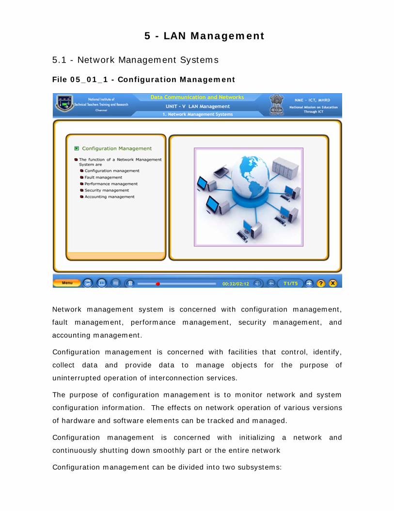
5 - LAN Management 5.1 - Network Management Systems File 05_01_1 - Configuration Management
Network management system is concerned with configuration management,
fault management, performance management, security management, and
accounting management.
Configuration management is concerned with facilities that control, identify,
collect data and provide data to manage objects for the purpose of
uninterrupted operation of interconnection services.
The purpose of configuration management is to monitor network and system
configuration information. The effects on network operation of various versions
of hardware and software elements can be tracked and managed.
Configuration management is concerned with initializing a network and
continuously shutting down smoothly part or the entire network
Configuration management can be divided into two subsystems:

• Reconfiguration and
• Documentation
Reconfiguration, involves adjusting the network components and features, which
could be a daily occurrence in a large network.
There are three types of reconfiguration:
hardware reconfiguration
software reconfiguration and
user-account reconfiguration
Hardware reconfiguration covers all changes to the hardware. For example, in a
desktop computer many components need to be replaced.
Software reconfiguration covers all changes to the software. For example new
software may need to be installed or updated on servers or clients.
User-account reconfiguration takes care of user privileges, both as an individual
and as a member of a group. For example, a user may have read and write
permission with regard to some files, but only read permission with regard to
other files.
The original network configuration and each subsequent change must be
recorded meticulously. There must be documentation for hardware, software,
and user accounts.
File 05_01_2 – Fault Management Fault management is concerned with the detection, isolation and correction of
abnormal operation of the network environment.
A fault is usually indicated by failure to operate correctly or operating with
excessive errors.
The purpose of fault management is to detect, log, notify users of, and (to the
extent possible) automatically fix network problems to keep the network running
effectively.
An effective fault management system comprise of two subsystems: reactive
fault management and proactive fault management.
Reactive fault management system handles short-term solutions to faults.
The first step to be taken by a reactive fault management system is to detect
the exact location of the fault.
A good example of a fault is a damaged communication medium. This fault may
interrupt communication or produce excessive errors.
The next step to be taken by a reactive fault management system is to isolate
the fault. A fault, if isolated, usually affects only a few users. After isolation,
the affected users are immediately notified and given an estimated time of
correction
The third step is that correction must be documented. The record should show
the exact location of the fault, the possible cause, the action or action taken to
correct the fault, the cost, and time it look for each step.
Proactive fault management tries to prevent occurrence of fault. Although,
this is not always possible, some types of failures can be predicted and
prevented. For example, if a manufacturer specifies a lifetime for a component
or a part of a component, it is a good strategy to replace it before that time.
File 05_01_3 – Performance management Performance management, tries to monitor and control the network to ensure
that it is running as efficiently as possible. Performance management tries to
quantify performance by using some measurable quantity such as capacity,
traffic, throughput, or response time.
Capacity
Every network has a limited capacity, and the performance management system
must ensure that it is not used above this capacity.
Traffic can be measured in two ways: internally and externally. Internal traffic
is measured by the number of packets (or bytes) traveling inside the network.
External traffic is measured by the exchange of packets (or bytes) outside the
network.

The Throughput of an individual device (such as a router) or a part of the
network can be measured. Performance management monitors the throughput
to make sure that it is not reduced to unacceptable levels.
Response time is normally measured from the time a user requests a service
to the time the service is granted. Performance management monitors the
average response time and the peak-hour response time. Any increase in
response time is a very serious condition as it is an indication that the network
is working above its capacity.
File 05_01_4 – Security Management
Security management deals with the aspects of network environment security essential to operate the network management correctly and to protect managed objects. Security management needs to keep track of generating, distributing and storing encryption keys. Passwords and other authorization or access control information must be maintained and distributed. Monitoring and controlling access to computer networks and access to all or part of the network management information must be attained from the network nodes. Logs are an important security tool. Security management is very much involved with the collection, storage and examination of audit records and security logs, as well as with the enabling and disabling of these logging facilities.
Security management provides the facilities for protection of network resources and user information. Network security facilities should be available for authorized users only.
File 05_01_5 – Accounting management
Accounting management deals with the facilities that enable charges to established for the use of managed objects and costs to be identified for the use of those managed objects.
Accounting management is the control of users’ access to network resources through charges. Under accounting management individual users, departments, divisions, or even projects are charged for the services they receive from the network. Charging does not necessarily mean cash transfer; it may mean debiting the departments or divisions for budgeting purposes. Today, organizations use an accounting management system for the following reasons:
• A user or group of users may be abusing their access privileges and burdening the network at the expense of other users
• Users may be inefficiently using the network, and the network
manager can assist in changing procedures to improve performance
• The network manager is in a better position to plan for
network growth if user activity is defined with sufficient details
5.1.6 Self Test
1. To monitor network and system configuration information, the _________ management is used.
A. Fault B. Performance C. Configuration D. Security
(Answer: Configuration)
2. Accounting management is the control of user’s access to network resources through _________.
(Answer: charges)
3. Performance management monitors the _________ to make sure that it is not reduced to unacceptable levels.
A. response time B. throughput C. reconfiguration D. traffic (Answer: throughput)
4. When a fault occurs, it is important to reconfigure or modify the network as
early as possible, in such a way as to minimize the impact of operation without the failed components.
• True • False (Answer: True)
5. Security management needs to keep track of generating, distributing and storing _________ key.
(Answer: encryption)

5.2 - Simple Network Management Protocols (SNMP) File 05_02_1 – Concept The Simple Network Management Protocol (SNMP) is a framework for managing devices in an internet using the TCP/IP protocol suite. It provides a set of fundamental operations for monitoring and maintaining an internet.
The SNMP model defines two entities, which works in a client-server mode. The server is called an agent and the client part is the SNMP manager. All other nodes in the network that is part of the network management system are referred to as agents. SNMP is an application-level protocol in which a few manager stations control a set of agents. The SNMP manager requests information from a SNMP agent, such as the amount of hard disk space available or the number of active sessions. The SNMP agent responds to SNMP manager requests for information.
Gathered information are then processed and displayed in tables, graphs, gauges, histograms, for an easier interpretation by human being. If the SNMP manager has been granted write access to an agent, that manager can also initiate a change to the agent's configuration.
The manager represents a software program that turns the computer into a Network Management Station (NMS). The agent represents software or firmware residing in a managed network device, such as a bridge, router or host. Each

agent stores management data and responds to SNMP manager queries for one or more data items.
The protocol is designed at the application level so that it can monitor devices made by different manufacturers and installed on different physical networks. In other words, SNMP frees management tasks from both the physical characteristics of the managed devices and the underlying networking technology. It can be used in a heterogeneous internet made of different LANs and WANs connected by routers made by different manufacturers.
File 05_02_2 – Management components To do management tasks, SNMP uses two other protocols:
• Structure of Management Information (SMI)
• Management Information Base (MIB)
Management on the internet is done through the cooperation of the three protocols SNMP, SMI, and MIB. SNMP has some very specific roles in network management.
• It defines the format of the packet to be sent from a manager to an agent and vice versa.
• It also interprets the result and creates statistics (often with the help of other management software).
• The packets exchanged contain the object (variable) names and their status (values). SNMP is responsible for reading and changing these values.
A SNMP manager checks an agent by requesting information that reflects the behavior of the agent.
A SNMP manager forces an agent to perform a task by resetting values in the agent database.
An SNMP agent contributes to the management process by warning the manager of an unusual situation.
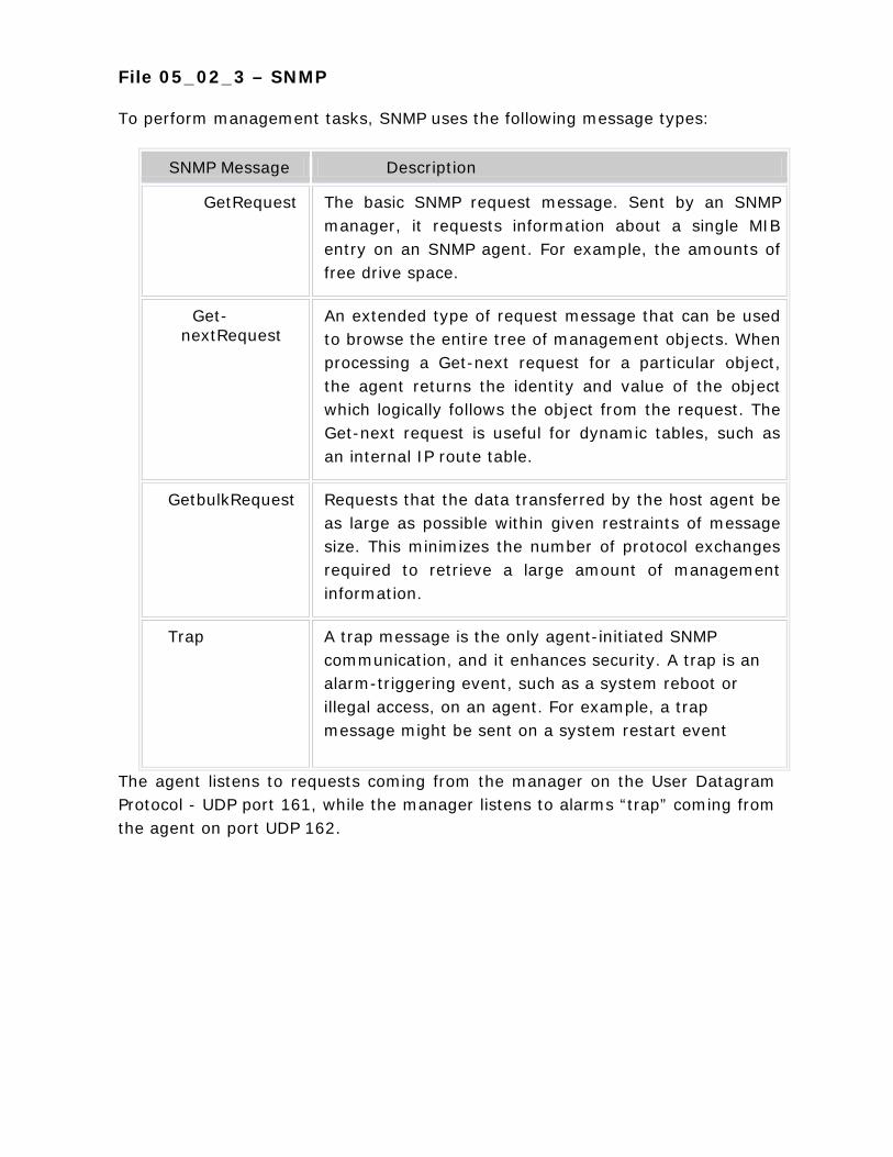
File 05_02_3 – SNMP To perform management tasks, SNMP uses the following message types:
SNMP Message Description
GetRequest The basic SNMP request message. Sent by an SNMP manager, it requests information about a single MIB entry on an SNMP agent. For example, the amounts of free drive space.
Get-nextRequest
An extended type of request message that can be used to browse the entire tree of management objects. When processing a Get-next request for a particular object, the agent returns the identity and value of the object which logically follows the object from the request. The Get-next request is useful for dynamic tables, such as an internal IP route table.
GetbulkRequest Requests that the data transferred by the host agent be as large as possible within given restraints of message size. This minimizes the number of protocol exchanges required to retrieve a large amount of management information.
Trap A trap message is the only agent-initiated SNMP communication, and it enhances security. A trap is an alarm-triggering event, such as a system reboot or illegal access, on an agent. For example, a trap message might be sent on a system restart event
The agent listens to requests coming from the manager on the User Datagram Protocol - UDP port 161, while the manager listens to alarms “trap” coming from the agent on port UDP 162.
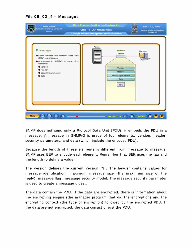
File 05_02_4 – Messages
SNMP does not send only a Protocol Data Unit (PDU), it embeds the PDU in a message. A message in SNMPv3 is made of four elements: version, header, security parameters, and data (which include the encoded PDU).
Because the length of these elements is different from message to message, SNMP uses BER to encode each element. Remember that BER uses the tag and the length to define a value.
The version defines the current version (3). The header contains values for message identification, maximum message size (the maximum size of the reply), message flag , message security model. The message security parameter is used to create a message digest.
The data contain the PDU. If the data are encrypted, there is information about the encrypting engine (the manager program that did the encryption) and the encrypting context (the type of encryption) followed by the encrypted PDU. If the data are not encrypted, the data consist of just the PDU.
File 05_02_5 – Troubleshooting
IPX Addresses
If you enter an IPX address as a trap destination when installing SNMP service, the following error message might appear when you restart your computer:
Error 3
This occurs when the IPX address has been entered incorrectly, using a comma or hyphen to separate a network number from a Media Access Control (MAC) address. For example, SNMP management software might normally accept an address like: 00008022,0002C0-F7AABD. However, the Windows 2000 SNMP service does not recognize an address with a comma or hyphen between the network number and MAC address.
The address used for an IPX trap destination must follow the IETF defined 8.12 format for the network number and MAC address. For example, the following format is valid, where xxxxxxxx is the network number and yyyyyyyyyyyy is the MAC address:
xxxxxxxx . yyyyyyyyyyyy
Event Viewer
SNMP error handling has been improved in Windows 2000 Server and Windows 2000 Professional.
Manual configuration of SNMP error - logging parameters has been replaced with improved error handling that is integrated with Event Viewer.
Use Event Viewer if you suspect a problem with the SNMP service. For troubleshooting procedures, see Windows 2000 Help.
To use Event Viewer
Click Start , point to Settings , click Control Panel , double-click Administrative Tools , and then double-click Event Viewer .
Select System Log .
Double-click an SNMP event in the Scope pane to display event details.
You can configure a View filter to display only SNMP messages. For more information about using Event Viewer, refer to Windows 2000 Help.
WINS Service
When querying a WINS server, you might need to increase the SNMP time-out period on the SNMP management system.
If some WINS queries work and others time out, increase the time-out period.
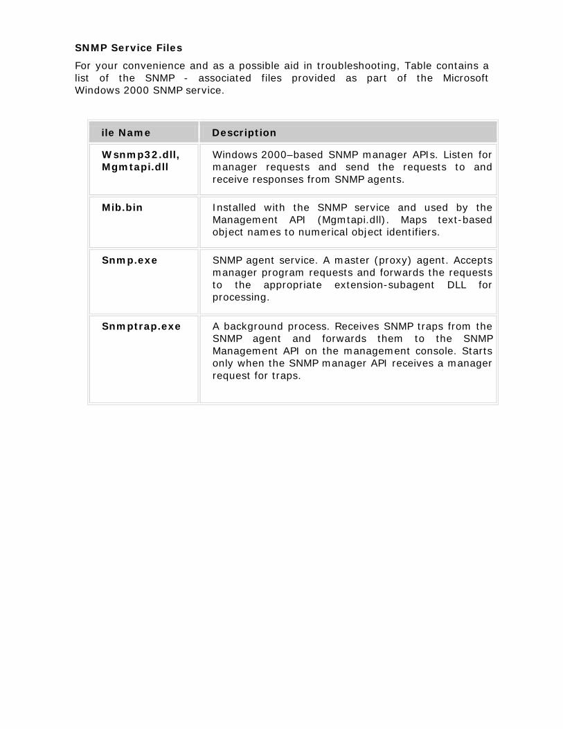
SNMP Service Files
For your convenience and as a possible aid in troubleshooting, Table contains a list of the SNMP - associated files provided as part of the Microsoft Windows 2000 SNMP service.
ile Name Description
Wsnmp32.dll, Mgmtapi.dll
Windows 2000–based SNMP manager APIs. Listen for manager requests and send the requests to and receive responses from SNMP agents.
Mib.bin Installed with the SNMP service and used by the Management API (Mgmtapi.dll). Maps text-based object names to numerical object identifiers.
Snmp.exe SNMP agent service. A master (proxy) agent. Accepts manager program requests and forwards the requests to the appropriate extension-subagent DLL for processing.
Snmptrap.exe A background process. Receives SNMP traps from the SNMP agent and forwards them to the SNMP Management API on the management console. Starts only when the SNMP manager API receives a manager request for traps.

5.2.6 Self Test
1. The Simple Network Management Protocol (SNMP) is a framework for managing devices in an internet using the _________.
A. FTP Protocol B. TCP / IP Protocol C. TCP / IP Protocol Suite D. Network Protocol (Answer: TCP / IP Protocol Suite)
2. SNMP does not define the format of packets exchanged between a manager and an agent and vice versa.
• True • False (Answer: False)
3. When the IPX address has been entered incorrectly, using a comma or hyphen to separate a network number from a Media Access Control (MAC) address, _________ occurs.
(Answer: Error 3)
4. Match the following
(A) Event Viewer - (1) Management System
(B) SNMP Manager - (2) Incorrect IPX Address
(C) WINS Service - (3) Windows 2000 Help
(D) Error 3 - (4) increase the SNMP time-out period
(E) SNMP Agent - (5) Maximum Message Size
- (6) Management Station
[Answer: (A) – (3) (B) - (6) (C) – (4) (D) – (2) (E) – (1)]
5. SMI does not define the number of objects an entity should manage, or name the objects to be managed or define the association between the objects and their values.
1. True 2. False (Answer: True)
6. To secure traffic between SNMP management systems and agents, _________ is used
A. TCP / IP Protocol security B. Internet Protocol security (IPSec) C. TCP / IP Protocol suite D. File Transfer Protocol
[Answer: Internet Protocol security (IPSec)
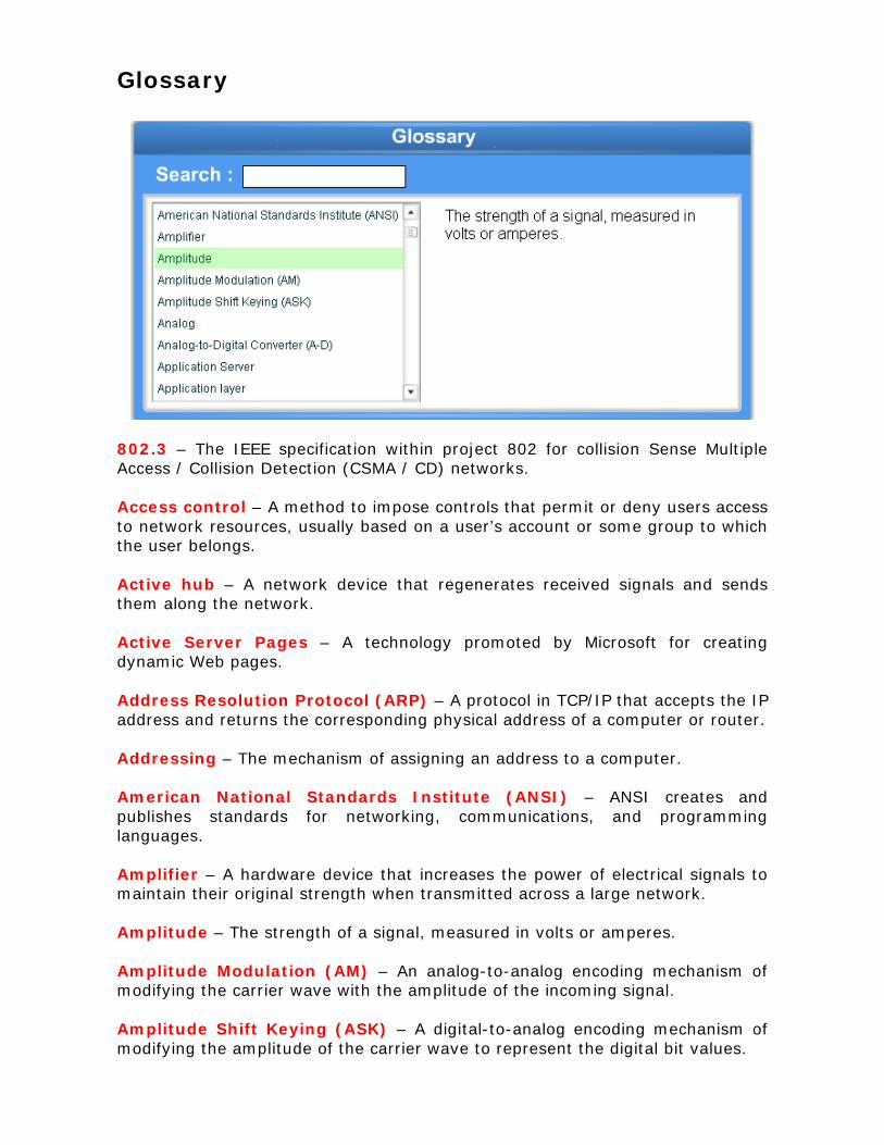
Glossary
802.3 – The IEEE specification within project 802 for collision Sense Multiple Access / Collision Detection (CSMA / CD) networks. Access control – A method to impose controls that permit or deny users access to network resources, usually based on a user’s account or some group to which the user belongs. Active hub – A network device that regenerates received signals and sends them along the network. Active Server Pages – A technology promoted by Microsoft for creating dynamic Web pages. Address Resolution Protocol (ARP) – A protocol in TCP/IP that accepts the IP address and returns the corresponding physical address of a computer or router. Addressing – The mechanism of assigning an address to a computer. American National Standards Institute (ANSI) – ANSI creates and publishes standards for networking, communications, and programming languages. Amplifier – A hardware device that increases the power of electrical signals to maintain their original strength when transmitted across a large network. Amplitude – The strength of a signal, measured in volts or amperes. Amplitude Modulation (AM) – An analog-to-analog encoding mechanism of modifying the carrier wave with the amplitude of the incoming signal. Amplitude Shift Keying (ASK) – A digital-to-analog encoding mechanism of modifying the amplitude of the carrier wave to represent the digital bit values.
Analog – The method of signal transmission used on broadband networks. Analog-to-Digital Converter (A-D) – A device that accepts analog pulses, and gives out digital bit information. Application layer – Layer 7 in the OSI reference model. The application layer provides interfaces to permit applications to request and received network services. Application Server – A specialized network server whose job is to provide access to a client/server application, and, sometimes, the data that belongs to that application as well. Asynchronous – A communication method that sends data in a stream with start and stop bits indicates where the data begins and ends. Asynchronous Transfer Mode (ATM) – A WAN technology that uses fiber–optic media to support up to 622–Mbps transmission rates. ATM uses no error checking and has a 53–byte fixed–length cell. Asynchronous transmission –A mechanism of data transmission in which the sender and the receiver do not require to synchronize before transmission begins; the sender can transmit the message at any time. ATM Layer – The second layer in the ATM protocol. Attenuation – The degradation and distortion of an electronic signal as it travels from its origin. Authentication – Establishing a proof of identity before communication can begin. Bandwidth – The range of frequencies that a communications medium can carry. Best effort delivery – A delivery mechanism that attempts to, but gives no guarantee of, the successful delivery of packet. Binary coded Decimal (BCD) – An encoding mechanism that uses four bits to encode each digit. Bit – Binary digit can have a value of 0 or 1. Bit rate – The transmission rate in case of digital signals, usually represented in Bits per second (BPS). Bits Per Second (BPS) – See Bit rate. Bridge – A networking device that works at the Data Link Layer of the OSI model. It filters traffic according to the packet’s hardware destination address is on.
British Naval Connector (BNC) – Also known as bayonet nut connector, bayonet navy connector or bayonet Neill-Concelman connector. This is a matching pair of coaxial cable connectors consists of a ferrule around a hollow pin with a pair of guideposts on the outside. Broadband ISDN (B – ISDN) – ISDN that offers high data rates, suitable for video transmission. BRouter – A networking device that combines the best functionality of a bridge and a router. It routes packets that include Network layer information and bridges all other packets. Browser– based emails – A technology that allows end users to access emails using the web browser interface. Browsing – Accessing Web pages with the help of a web browser. Bus - A Major network topology in which the computers connector to a backbone cable segment to form a straight line. Bus topology – A network arrangement where in all the computers are attached to a shared medium. Byte – Usually, but not always, a combination of eight bits. Cable modem – A device that allows the transmission of Internet data over cable television networks. Carrier Sense Multiple Access with Collision Avoidance (CSMA/CA) – A connection-based channel access method in which computers avoid collisions by broadcasting their intent to send data. Carrier Sense Multiple Access with Collision Detection (CSMA/CD) – A Connection-based channel access method in which computers avoid collisions by listening to the network before sending data. Cladding – A nontransparent layer of plastic or glass material inside fiber-optic that surrounds the inner core of glass or plastic fibers. Client – A computer on a network that requests resources or services from some other computer. Client/server – A model for computing in which some computers (clients) request services and others (servers) respond to such requests for services. Client/server computing – A computing environment in which the processing is divided between the client and the server. Coaxial cable – A type of cable that uses a center conductor, wrapped by an insulating layer, surrounded by a braided wire mesh and an outer jacket, to carry high-bandwidth signals such as network traffic.
Collision – Occurs when two computers put data on the cable at the same time. This corrupts the electronic signals in the packet and causes data loss. Combination Network – A network that incorporates both peer-to-peer and server based capabilities. Communication server – A specialized network server that provides access to resources on the network for users not directly attached to the network. Compression – Reduction of message size without impacting its contents to reduce transmission demands. Congestion – Slow state of the network caused by too many senders, receivers or transmission. Congestion Control – A technique for monitoring network utilization and manipulating transmission to keep traffic levels from overwhelming the network medium; gets its name because it avoids “network traffic jams”. Connection-oriented – A type of protocol that establishes a formal connection between two computers, guaranteeing the data will reach its destination. Connectionless – A type of protocol that sends the data across the network to its destination without guaranteeing receipt. Crosstalk – A phenomenon that occurs when two wires lay against each other in parallel. Signals traveling down one wire can interfere with signals traveling down the other and vice versa. Cryptography – The art of encoding and decoding messages so as to product the contents of the messages from the eyes of those not authorized to read them. CPU – An abbreviation for Central Processing Unit, the collection of circuitry (a single chip on most PC’s) that supplies the “brains” for most computers. Cyclic Redundancy Check (CRC) – The CRC is calculated before transmission of a data frame and then included with the frame; on receipt, the CRC is recalculated and compared to the sent value. Data channel – The cables and infrastructure of a network. Data (D) channel – An ISDN channel used primarily for carrying control signals, which can also be used for low– speed data transfers. Data Encryption Standard (DES) – A symmetric key encryption algorithm, originally developed by IBM. Data Link control (DLC) – A network protocol used mainly by Hewlett-Packard printers and IBM Mainframes attached to a network.
Data Link Layer – Layer 2 in the OSI reference model. This layer is responsible for managing access to the networking medium and for ensuring error-free delivery of data frames from sender to receiver. Dedicated Server – A network server that acts only as a server and is not intended for regular use as a client machine. Delta modulation – A modified version of Pulse Code Modulation, which measures only changes to adjacent signal values. Demodulator – Opposite of modulator, this equipment transforms analog signals to digital values. Demultiplexer – Opposite of multiplexer, this equipment separates multiple signals on a single medium to obtain individual signals. Device Driver – A software program that mediates communication between an operating system and a specific device for the purpose of sending and/or receiving input and output from that device. Device sharing – A primary purpose for networking: permitting users to share access to devices of all kinds, including servers and peripherals such as printers and plotters. Diagram – The term used to describe a network’s design. Digital – An encoding mechanism that consists of discrete values. Digital–to–Analog Converter (D–A) – Equipment that transforms digital pulses into analog signals. Distortion – Distortion resulting from non – uniform speed of transmission of the various frequency components of a signal through a transmission medium. Domain – A uniquely named collection of user accounts and resources that share a common security database. Domain Controller – On networks based on Windows NT server or windows 2000 Server, a directory server that also provides access controls over users, accounts, groups, computers, and other network resources. Domain model – A network based on Windows NT Server or Windows 2000 Server whose security and access controls reside in a domain controller. Domain Name System (DNS) – A TCP/IP protocol used to associate a computer’s IP address with a name. Dual bus – Two buses.
Duplication control – Mechanism that prevents processing of duplicate packets. e-mail – An abbreviation for electronic mail, a networked application that permits users to send text messages, with or without attachments of many kinds, to individual or multiple users. Encryption – The mechanism of encoding messages to achieve security objectives. Error control – Detection of errors in transmission. Error-handling – The process of recognizing and responding to network transmission or reception errors. These errors are usually interminable delivery (time-out), incorrect delivery. Ethernet – A networking technology developed in the early 1970s and governed by the IEEE 802.3 specification. Ethernet remains the most popular type of networking technology in use today. Ethernet 802.2 – Ethernet frame type used by IPX / SPX on Novell Net Ware 3.12 and 4.x networks. Ethernet 802.3 – Ethernet frame type generally used by IPX / SPX on Novell Netware 2.x and 3.x networks. Ethernet II – Ethernet frame type used by TCP / IP. Even parity – A error detection mechanism based on the total number of 1 s in a message being 0. Exchange Server – A Back office component from Microsoft that acts as a sophisticated e-mail server. Extended Binary Coded Decimal Interchange Code (EBCDIC) – An encoding scheme used primarily in IBM mainframes. Extended LAN – The result of certain wireless bridges ability to expand the span of a LAN as far as three to 25 miles. Microsoft calls the resulting networks “extended LANs”. Fast Ethernet – The 100 - Mbps implementation of standard Ethernet. Fault Tolerance – A feature of a system, which allows it to continue working after an unexpected hardware or software failure. Fiber Distributed Data Interface (FDDI) – A limited–distance linking technology that uses dual, counter-rotating fiber-optic rings to provide 100-Mbps fault-tolerant transmission rates.

Fiber-optic – A cabling technology that uses pulses of light sent along a light conducting fiber at the heart of the cable to transfer information from sender to receiver. File Transfer Protocol (FTP) – A TCP / IP-based networked file transfer application, with an associated protocol. It’s widely used on the Internet to copy files from one machine on a network to another. Firewall – A special Internet server than sits between an Internet link and a private network, which filters both incoming and outgoing network traffic. Flow Control – An action designed to regulate the transfer of information between a sender and a receiver. Fragmentation – The process of breaking a long PDU from a higher layer into a sequence of shorter PDUs for a lower layer, ultimately for transmission as a sequence of data frames across the networking medium. Frame – Used interchangeably with “data frame”, the basic package of bits that represents a PDU sent from one computer to another across a network. Frame Relay – A WAN technology that offers transmission rates of 56Kbps to 10544 Mbps. Frame relay uses no error checking. Frame Type – One of four standards that define the structure of an Ethernet packet: Ethernet 802.3, Ethernet 802.2, Ethernet SNAP, or Ethernet II. Frequency – The number of times a signal changes its value in one second. Frequency modulation (FM) – An analog–to–analog encoding method in which the frequency of the carrier wave is a function of the modulating wave. Full-duplex Communications – A type of network communication in which a pair of networked devices can send and receive data at any given time providing two-way communications. Gateway – A networking device that translates information between protocols or between completely different networks, such as from TCP / IP to SNA. Gigabit Ethernet – An IEEE standard (802.3z) that allows for 1000-Mbps transmission using CSMA / CD and Ethernet frames. Go–back–n – An error–control mechanism in which all the frames including and after the one in error must be retransmitted. Group – Combination of smaller transmission lines. Half-duplex Communications – A type of network communication in which only one member of a pair of networked devices can transmit data at any given time.

Hertz (Hz, KHz, MHz, GHz) – A measure of broadcast frequencies, in cycles per second; named after Heinrich Hertz, one of the inventors of radio communications. Hexadecimal – A mathematical notation for representing numbers in base 16. The number 10 through 15 are expressed as A through F; 10th or 0x10 (both notations indicate the number is hexadecimal) equals 16. High-level Data Link Control (HDLC) – A synchronous communication protocol. Hub – The central concentration point of a star network. Hybrid Network – A network that incorporates both peer-to-peer and server based capabilities. Hyper Text Markup Language (HTML) – The language used to create documents for the WWW. Hyper Text Transfer Protocol (HTTP) – The protocol used by the WWW to transfer files. Industry Standard Architecture (ISA) – Originally an 8-bit PC bus architecture but upgraded to 16-bit with the introduction of the IBM PC / AT in 1984. Infrared – That portion of the electromagnetic spectrum immediately below visible light. Infrared frequencies are popular for short – to medium – range (10s of meters to 40 km) point – to – point network connections. Institute of Electrical and Electronics Engineers (IEEE) – An Engineering Organization that issues standards for electrical and electronic devices, including network interfaces, cabling, and connectors. Integrated Services Digital Network (ISDN) – A WAN technology that offers increments of 64-Kbps connections, most often used by SOHO (small office/home office) users. International Standardization Organization (ISO) – The international standards-setting body, based in Geneva, Switzerland, that sets worldwide technology standards. Also called International Standards Organization. Internet – The global collection of networked computers that began with technology and equipment funded by the U.S. Department of Defense in the 1970’s. Internet Browser – A graphical tool designed to read HTML documents and access the WWW, such as Microsoft Internet Explorer or Netscape Navigator. Internet Information Server (IIS) – A Microsoft Back office component that acts as a Web-server in the Windows NT Server environment.
Internet Information Services (IIS) – The Windows 2000 version of Internet Information server. Internet Protocol (IP) – TCP / IP’s primary network protocol, which provides addressing and routing information. Internet Service Provider (ISP) – A company that connects its clients to the Internet. Intranets – An in-house TCP / IP – based network, for use within accompany. Industry Request Line (IRQ) – IRQs define the mechanism whereby a peripheral device of any kind, including a network adapter, can stake a claim on the PC’s attention called “interrupt”. Jacket – The outermost layer of a cable. Jitter – A tendency toward lack of synchronization caused by mechanical or electrical changes. Latency – The amount of time a signal takes to travel from one end of a cable to the other. Layers – The functional subdivisions of the OSI reference model. The model defines each layer in terms of the services and data it handles on behalf of the layer directly above it and the layer directly below it. Local Area Network (LAN) – A collection of computers and other networked devices that fit within the scope of a single physical network and provide the building blocks for internetworks and WANs. Local host – A special DNS host name that refers whatever IP address is assigned to the machine where this name is referenced. MAC address – The unique address programmed into a NIC that the MAC layer handles. The MAC address identifies the NIC on any network in which it appears. Mail servers – A networked server that manages the flow of e-mail messages for network users. Media Access Control (MAC) - The longest legal segment of cable that a particular networking technology permits. This limitation makes sure for network designers and installers that the entire network can send and receive signals properly. Mesh – A hybrid network topology use for fault tolerance in which all computers connect to each other. Mesh Topology – A topology in which each node is connected to every other node.
Metropolitan area network (MAN) - Uses WAN technologies to interconnect LANs within a specific geographic region, such as a country or a city. Microwave – Electromagnetic waves ranging from 2 GHZ to 40 GHZ. Modem (Modulator/Demodulator) – Used by computers to convert digital signals to analog signals for transmission over telephone lines. The receiving computer then converts the analog signals to digital signals. Multicast packet – A packet that uses a special network address to make itself readable to any receiving computer that wants to read its payload. Multicast packets. Multiplexer – The device that is used in multiplexing. Multiplexing – The networking technology that combines several communications on a single cable segment. Network Adapter – A synonym for network interface card (NIC). It refers to the hardware device that mediates communication between a computer and one or more types of networking media. Network Address – The number that identifies the physical address of a computer on a network. This address is hard-wired into the computer’s NIC. Network Administrator – An individual responsible for installing, configuring, and maintaining a network, usually a server-based network such as Windows 2000 Server or Novell Netware. Network Card – A synonym for network interface card (NIC). Network File System (NFS) – A distributed file system originally developed at Sun Microsystems. It supports network-based file and printer sharing using TCP/IP- based network protocols. Network Interface Card (NIC) – A PC adapter board designed to permit a computer to be attached to one or more types of networking media. Network Layer – The Network Layer handles addressing and routing of PDUs across internetworks in which multiple networks must be traversed between sender and receiver. Network Protocol – A set of rules for communicating across a network. To communicate successfully across a network, two computers must share a common protocol. Network Resources – Any kind of device, information, or service available across a network. Node – An addressable communication device, such as a computer or a router.
Node–to–node delivery – Delivery of packets from one node to the next one. Noise – Random electrical signals that can be picked up during transmission, causing degradation or distortion of data. Odd parity – An error–detection method in which an extra bit is added to the data unit so that the sum of all 1–bits becomes odd. Open System Interconnection (OSI) – The family of ISO standards developed in 1970s and 1980s and designed to facilitate high-level, high-function networking services among dissimilar computers on a global scale. Optical fiber – A high–bandwidth transmission system that sends data bits as light pulses. OSI Reference Model – It defines a frame of reference for understanding and implementing networks by breaking down the process across seven layers. Packet – A specially organized and formatted collection of data destined for network transmission; alternatively, the form in which network transmissions are received following conversion into digital form. Packet Header – Information added to the beginning of the data being sent, which contains, among other things, addressing and sequencing information. Packet Trailer – Information added to the end of the data being sent, which generally contains error-checking information such as the CRC. Parallel transmission – Transmission mechanism where multiple bits are sent at the same time, each on a separate wire. Parity bit – The additional bit added to a packet for error detection. Parity checking – The mechanism of error detection using parity bits. Passive Hub – A central connection point that signals pass through without regeneration. Peer-to-Peer – A type of networking in which each computer can be a client to other computers and act as a server as well. Period – The time required for a signal to complete one cycle. Phase – The relative signal of a position with respect to time. Physical Layer – The Physical Layer transmits and receives signals, and specifies the physical details of cables, adapter cards, connectors, and hardware behavior.
Point-to-Point Protocol (PPP) – A remote access protocol that supports many protocols including TCP/IP, NetBEUI, and IPX/SPX. Presentation Layer – Platform-specific application formats are translated into generic data formats for transmission or from generic data formats into platform-specific application formats for delivery to the Application Layer. Propagation Delay – Signal delay created when a number of repeaters connect in a line. Protocol – A rigidly defined set of rules for communication across a network. Protocol Suite – A family of related protocols in which higher-layer protocols provide application services & request handling facilities, while lower-layer protocols manage the intricacies of Layer1 through 4 from the OSI reference model. Proxy Server – A special Internet server that sits between an Internet link and a private network. Pulse Code Modulation (PCM) – Digitizing analog signals using sampling and quantizing techniques. Quadrate Amplitude Modulation (QAM) – A digital–to–analog encoding technique where the amplitude and the phase values of the carrier wave can be changed to represent digital information. Quantizing – Measuring sampled analog signals to get their numeric equivalents. Radio-Frequency Interface (RFI) – Any interference caused by signals operating in the radio frequency range. Random Access Memory (RAM) – The memory cards or chips on a PC that provide working space for the CPU to use when running applications, providing network services, and so on. Raw Data – Data streams unbroken by header information. Receiver – A data communications device designed to capture and interpret signals broadcast at one or more frequencies in the Electro magnetic spectrum. Registered Jack (RJ) – Used for modular telephone and network TP jacks. Repeater – A networking device that regenerates electronic signals, so that they can accommodate additional computers on a network segment. Request-Response – A way of describing how the client/server relationship works that refers to how a request from a client leads to some kind of response from a server.

Ring – Topology consisting of computers connected in a circle, forming a closed ring. Ring topology – A topology where in all the devices are connected to each other to form a ring. RJ-11 – The four-wire modular jack commonly used for home telephone handsets. RJ-45 – The eight-wire modular jack for TP networking cables and also for PBX-based telephone systems. Router – A networking device that operates at the Network Layer of the OSI model. Routing table – A table maintained by a router to decide how to route the incoming packets to its ultimate destination. RSA algorithm – A public key encryption algorithm invented by Rivest, Shamir and Adleman. Routing – The process of moving data across multiple networks via router. Sampling – The first process in Pulse Code Modulation analog signal is measured periodically. Satellite Microwave – A Microwave transmission system that uses geosynchronous satellites to send and relay signals between sender and receiver. Security – For networking, security generically describes the set of access controls and permissions in place that determine if a server can grant a request for a service or resource from a client. Segmentation – The action of decomposing a larger, upper-layer PDU into a collection of smaller, lower-layer PDUs. Serial transmission – Transmission mechanism where in one bit is sent at a time, using a single wire. Server – A computer whose job is to respond requests for services or resources from clients else where on a network. Session Layer – The session layer is responsible for setting up, maintaining, and ending ongoing sequences across a network communications on a network. Sharing – One of the fundamental justifications for networking. Sheath – The outer layer of coating on a cable; sometimes also called the jacket.
Shielded Twisted Pair – A variety of TP cable, wherein a foil wrap encloses each of one or more pairs of wires for additional shielding. Shielding – Any layer of material included in cable for the purpose of mitigating the effects of interference on the signal-carrying cables it encloses. Signal – Electromagnetic wave propagating across a transmission medium. Simple Mail Transport Protocol (SMTP) – A TCP/IP protocol used to send mail messages across a network. SMTP is the basis for e-mail on the Internet. Simple Network Management Protocol (SNMP) – A TCP/IP protocol used to monitor and manage network devices. Simplex transmission – Transmission system where one side can only transmit, the other side can only receive. Sliding window – A protocol that allows several data units to transmit before an acknowledgement is received. Source address – The address of the sender of a message. Star – Major topology in which the computers connect via a central connecting point, usually a hub. Star Bus – A network topology that combines the star and bus topologies. Star Ring – A network topology wired like a star that handles traffic like a ring. Star topology – A topology in which all stations are attached to a central device (hub). Stop–and–wait– Flow control mechanism where each data unit must be acknowledged before the next one can be sent. Straight Connection (SC) – A type of one-piece fiber-optic connector that pushes on yet makes a strong and solid contact with emitters and sensors. Straight Tip (ST) – The most common type of fiber-optic connector used in Ethernet networks with fiber backbones. Switch – A special networking device that manages networked connections between any pair of star-wired devices on a network. Switching – Using a network switch to manage media or channel access. Synchronous – Communications type in which computers rely on exact timing and sync bits to maintain data synchronization. Telnet – A TCP/IP protocol that provides remote terminal emulation.

Terminator – Used to absorb signals as they reach the end of a bus. Terrestrial Microwave – A wireless microwave networking technology that uses line-of-sight communications between pairs of Earth-based transmitters and receivers to relay information. Thin wire – A synonym for 10Base2, and cheapernet. Token – Used in some ring topology networks to ensure fair communications between all computers. Token bus – A LAN technology that uses token passing access method and bus topology. Token Passing – A channel access method used mostly in ring topology networks. Token Ring – A network architecture developed by IBM, which is physically wired as a star but uses token passing in a logical ring topology. Topology – A basic physical layout of a network. Transceiver – A device that both transmits and receives messages. Translation – A change from one protocol to another. Transmission Control Protocol /Internet Protocol (TCP/IP) – A protocol suite that supports communication between heterogeneous systems. TCP/IP has become the standard communications protocol for the Internet. Transmission medium – The wire that carries signals between the communicating parties. Transmitter – An electronic device capable of emitting signals for delivery through a particular networking medium. Transport Layer – The transport layer is responsible for fragmenting large PDUs from the session layer for delivery across the network. Transport Protocol – A protocol type responsible for providing reliable communication sessions between two computers. Troubleshooting – The techniques involved in detecting problems and identifying causes. Twisted-Pair (TP) – A type of cabling where two copper wires, each enclosed in some kind of sheath, are wrapped around each other. Unguided transmission media – A transmission medium that has no physical boundaries.

Unshielded twisted-pair (UTP) – A form of TP cable that includes no additional shielding material in the cable composition. User Datagram Protocol (UDP) – A connectionless TCP/IP protocol that provides fast data transport. Vertical Redundancy Check (VRC) – An error– detection mechanism based on the parity checking of each character. Virtual Circuit – A logical circuit between the sender and the receiving computer. All the packets in the transmission then follow the same route and always arrive in order. Virtual LAN (VLAN) – A configuration setting that groups two or more devices attached to a switch. Web browser – The client-side software that’s used to display content from the World Wide Web (WWW). Web Server –A server that hosts HTML pages and dispatches them on request. Wide Area Network (WAN) – An internetwork that connects multiple sites, where a third-party communications carrier, such as a public or private telephone company. Wireless – Indicates that a network connection depends on transmission at some kind of electromagnetic frequency through the atmosphere to carry data transmission from one networked device to another. Wireless Bridge – A pair of devices, typically narrow-band and tight beam, that relay network traffic from one location to another. World Wide Web (WWW, W3 or web) – The TCP/IP based collection of all Web servers on the Internet. X.25 – An international standard for wide-area packet-switched communications. X.25 offers 64-Kbps network connections and uses error checking.

Course Summary
The basis of all computer-to-computer data communications is the concept of signal propagation. The simple idea in signal propagation is that when some kind of signal is applied in any form (such as heat, voltage or current) to one end of a conducting material, after some time the signal reaches the other end of the material. Any sinusoidal signal has three properties, namely, amplitude which refers to the strength of the signal, period which refers to the time taken by a signal to complete one cycle and frequency which refers to the number of signal changes in one second. The bandwidth of a signal is the difference between its highest and lowest frequencies. An analog signal is a continuous waveform. A digital signal is a discrete waveform. The bandwidth of a digital signal is infinite. A group of several computers connected by communication media is termed as computer network. Some of the applications of computer networks are file sharing, hardware sharing, and electronic mail. In the client/server model of networking, the client submits the information to the server, which processes the information and returns the results to the client station.
When data is transmitted from a sender to a receiver, there is a scope for transmission errors. To deal with the transmission errors, there are 2 steps: error detection and error correction. The most important issues related to the data link layer of the OSI model are flow control and error control. The components of a network are network interface card, network operating system, and the transmission medium. Computers can be connected in the form of star, ring, bus, full-connected, tree and hybrid topologies. The types of networks are LAN, MAN, WAN, and Internet.
Reference

References:
1) Achyut S Godbole. (2004). “Computer Communication Networks”, New Delhi: Tata McGraw Hill Publishing Company Ltd. 2) Andrew S. Tanenbaum. (2003). “Computer Networks”, New Delhi: Prentice- Hall of India Private Limited. 3) Behrouz A Forouzan. (2006). “Data Communication and Networking” New Delhi: Tata McGraw Hill Publishing Company Ltd., 4) Douglas E. Comer and Narayanan M.S. (2009). “Computer Networks and Internets with Internet Applications”, New Delhi: Pearson Education Inc. and Dorling Kinders Pvt. Ltd. 5) Elahi. (2002). “Network Communications Technology”, Bangalore Delmar and Thomson Learning Inc., 6) Gilbert Held. (1999). “Understanding Data Communication New Delhi: Techmedia. 7) James E. Shuman. (1998). “Multimedia in Action”, New Delhi: Cengage Learning India Private Limited. 8) Madhulika Jain and Satish Jain. (2008). “A Level Made Simple Data Communication and Computer Networks”, New Delhi: BPB Publications.
9) Taylor, ED. (2000). “Networking Handbook”, New Delhi: Tata McGraw-Hill Publishing Company Limited.
10)Tittel, ED. (2002). “Theory and Problems of Computer Networking”, New Delhi: Tata McGraw-Hill Publishing Company Limited.
11)Wayne Tomasi. (2011). “Introduction to Data Communications and Networking”, New Delhi: Pearson Education Inc. and Dorling Kindersley (India) Pvt. Limited.
12)William Stallings. (2004). “Computer Networking with Internet Protocols and Technology”, New Delhi: Pearson Education.