establishing geothermal energy research at university ... · establishing geothermal energy...
TRANSCRIPT

Establishing Geothermal Energy Research at
University College Dublin
Engineers Ireland Geotechnical Engineering Society, Civil
Engineering Society & International Association of Hydrogeologists
Event
January 2013
Dr Phil Hemmingway UCD School of Biosystems Engineering

Presentation Outline
1. Ground Source Energy System Types
2. Open Loop Investigations (Chemistry & Settlement)
3. Thermal Response Testing (TRT)
4. Laboratory Thermal Characterization Equipment
5. Energy Foundations
6. Finite Element Analyses
7. Concluding Remarks & Contact Details
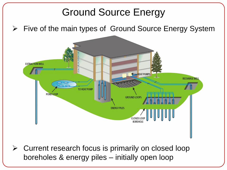
Ground Source Energy
Five of the main types of Ground Source Energy System
Current research focus is primarily on closed loop
boreholes & energy piles – initially open loop

Open Loop Investigations
Water Chemistry & Settlement (Cork Docklands)
Not routinely investigated
Aware of pumping tests in the area
Settlement: Highly compressible alluvium means
pumping induced settlement possible
Chemistry: Potentially an issue due to former
industrial use of site & saline intrusion

Open Loop Investigations
Settlement Calculations
Refer to “Geotechnical and structural aspects of
open loop geothermal systems” by Mike Long from
GAI conference 2008
Settlement is a potential issue for open loop systems
but it is entirely predictable and mitigation techniques
are well established to deal with the consequences
For Gravels For Clays

Open Loop Investigations
Water Chemistry Results (Cork Docklands)
*Based on BS EN 15450:2007 & other publications
Parameter Measured Required* Comment
pH Value 5.57 6.5 to 9.0 Lower Values = Typically Higher
Corrosion Rates
Chloride
(ppm) 5,660 < 300
Issues for HP’s with Stainless Steel,
Copper, Cupro-nickle or Titanium
Elec.
Conductivity
(μS/cm)
19,325 50 to 1,000 Drinking Water ≈ 5 – 500 μS/cm
RSI (Ryznar
Stability) 7.9 5 to 7 Indicative of “Heavy Corrosion”
LSI (Langelier
Saturation) - 1.1 - 0.5 to 0.5
- 0.5 = Slightly Corrosive;
- 2.0 = Serious Corrosion
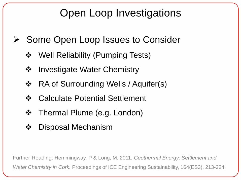
Open Loop Investigations
Some Open Loop Issues to Consider
Well Reliability (Pumping Tests)
Investigate Water Chemistry
RA of Surrounding Wells / Aquifer(s)
Calculate Potential Settlement
Thermal Plume (e.g. London)
Disposal Mechanism
Further Reading: Hemmingway, P & Long, M. 2011. Geothermal Energy: Settlement and
Water Chemistry in Cork. Proceedings of ICE Engineering Sustainability, 164(ES3), 213-224
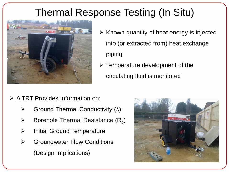
Thermal Response Testing (In Situ)
Known quantity of heat energy is injected
into (or extracted from) heat exchange
piping
Temperature development of the
circulating fluid is monitored
A TRT Provides Information on:
Ground Thermal Conductivity (λ)
Borehole Thermal Resistance (Rb)
Initial Ground Temperature
Groundwater Flow Conditions
(Design Implications)
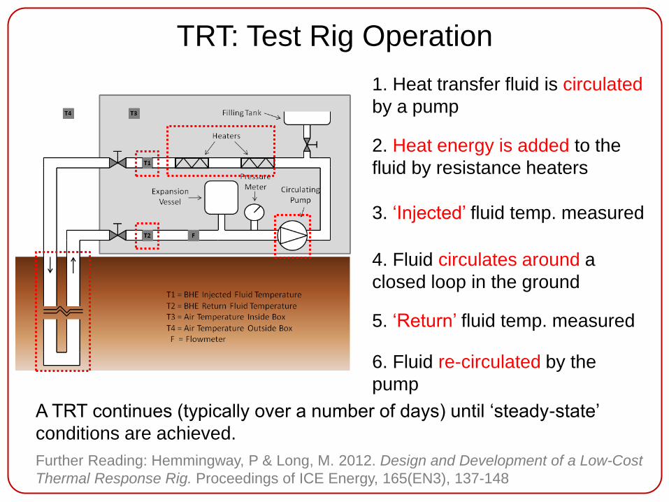
TRT: Test Rig Operation
1. Heat transfer fluid is circulated
by a pump
2. Heat energy is added to the
fluid by resistance heaters
3. ‘Injected’ fluid temp. measured
4. Fluid circulates around a
closed loop in the ground
5. ‘Return’ fluid temp. measured
6. Fluid re-circulated by the
pump
A TRT continues (typically over a number of days) until ‘steady-state’
conditions are achieved.
Further Reading: Hemmingway, P & Long, M. 2012. Design and Development of a Low-Cost
Thermal Response Rig. Proceedings of ICE Energy, 165(EN3), 137-148
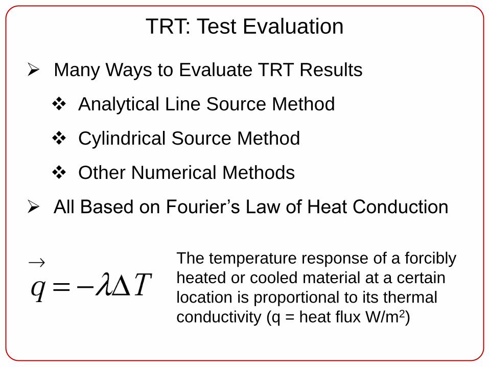
Many Ways to Evaluate TRT Results
Analytical Line Source Method
Cylindrical Source Method
Other Numerical Methods
All Based on Fourier’s Law of Heat Conduction
The temperature response of a forcibly
heated or cooled material at a certain
location is proportional to its thermal
conductivity (q = heat flux W/m2)
TRT: Test Evaluation
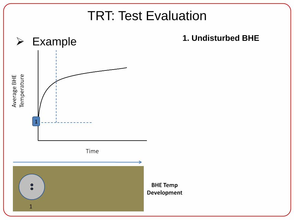
Example 1. Undisturbed BHE
TRT: Test Evaluation
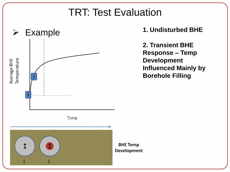
Example 1. Undisturbed BHE
2. Transient BHE
Response – Temp
Development
Influenced Mainly by
Borehole Filling
TRT: Test Evaluation

Example 1. Undisturbed BHE
2. Transient BHE
Response – Temp
Development
Influenced Mainly by
Borehole Filling
3. Start of Steady
State
TRT: Test Evaluation

Example 1. Undisturbed BHE
2. Transient BHE
Response – Temp
Development
Influenced Mainly by
Borehole Filling
3. Start of Steady
State
4. Stable Heat Flow –
Temp Development
Influenced by Ground
TRT: Test Evaluation

Equation above
describes ‘The
Temporal Evolution
of the Mean Fluid
Temperature’
Therefore Can
Determine ‘k’ if Plot
Av. BHE Temp vs.
Ln(Time)
TRT: Test Evaluation
Example - LSM
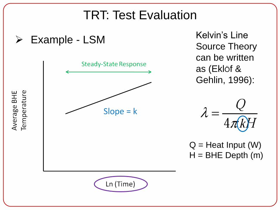
Example - LSM Kelvin’s Line
Source Theory
can be written
as (EklÖf &
Gehlin, 1996):
Q = Heat Input (W)
H = BHE Depth (m)
TRT: Test Evaluation
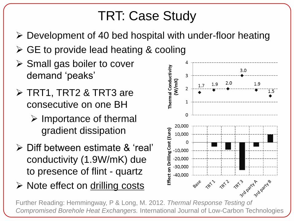
TRT: Case Study
Development of 40 bed hospital with under-floor heating
GE to provide lead heating & cooling
Small gas boiler to cover
demand ‘peaks’
TRT1, TRT2 & TRT3 are
consecutive on one BH
Importance of thermal
gradient dissipation
Diff between estimate & ‘real’
conductivity (1.9W/mK) due
to presence of flint - quartz
Note effect on drilling costs
Further Reading: Hemmingway, P & Long, M. 2012. Thermal Response Testing of
Compromised Borehole Heat Exchangers. International Journal of Low-Carbon Technologies

Lab Thermal Conductivity Testing
Blue dots = measurement values
Red line = trend line….calc of T.C.
UCD Thermal Probe System:
Lab measurement of soil and soft rock;
ASTM standard available
x Require ~7inch rock core; Careful (&
sometimes time consuming) drilling of
core sample required
System Operation:
1. Probe inserted into test specimen;
2. Heat energy applied;
3. Time series temperature data
during heating measured by a
thermocouple;
4. Analysis of data.

Lab Thermal Conductivity Testing
UCD Single-Source Thermal System:
Lab measurement of concrete, grout
and soft soils
x Not suitable for measurement of hard
rock samples (difficult to prepare
required sample size)
System Operation:
1. Specimen is prepared to fit mould;
2. Heat energy applied;
3. Temperature development measured
at several points within specimen;
4. Steady-state conditions are achieved;
5. Analysis of data.
Thermal
Grout
‘Standard’ s/c Grouts
Th
erm
al
Co
nd
ucti
vit
y
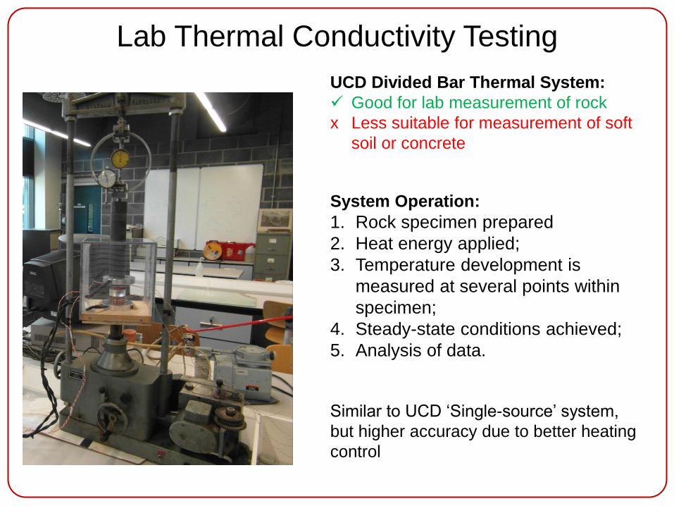
Lab Thermal Conductivity Testing
UCD Divided Bar Thermal System:
Good for lab measurement of rock
x Less suitable for measurement of soft
soil or concrete
System Operation:
1. Rock specimen prepared
2. Heat energy applied;
3. Temperature development is
measured at several points within
specimen;
4. Steady-state conditions achieved;
5. Analysis of data.
Similar to UCD ‘Single-source’ system,
but higher accuracy due to better heating
control
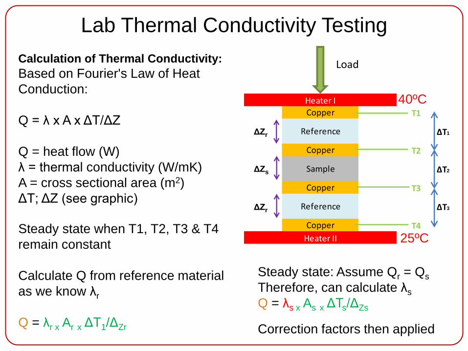
Lab Thermal Conductivity Testing
Calculation of Thermal Conductivity:
Based on Fourier's Law of Heat
Conduction:
Q = λ x A x ΔT/ΔZ
Q = heat flow (W)
λ = thermal conductivity (W/mK)
A = cross sectional area (m2)
ΔT; ΔZ (see graphic)
Steady state: Assume Qr = Qs
Therefore, can calculate λs
Q = λs x As x ΔTs/ΔZs
Correction factors then applied
T1
ΔT1
T2
ΔT2
T3
ΔT3
T4
Reference
Copper
Heater I
Heater II
Copper
Copper
Reference
Sample
Copper
Load
ΔZr
ΔZr
ΔZs
40ºC
25ºC Steady state when T1, T2, T3 & T4
remain constant
Calculate Q from reference material
as we know λr
Q = λr x Ar x ΔT1/ΔZr

Energy Foundation Installation
Research Installation
a) Loop Preparation b) CFA Drilling

Energy Foundation Installation
Research Installation
c) Loop Installation d) Pushing Last Few Feet

Energy Foundation Installation
Lessons Learned
Schedule Small Number of Installations for First Day
of Piling Schedule
Contingencies for Unsuccessful Installations (FOS)
Tailor Concrete Mix Design (Aggregates & Viscosity)
Fill Pipes with Water to Counteract Buoyancy
Protection of Pipes During all Phases of Construction
Further Reading: Hemmingway, P & Long, M. 2011. Energy Foundations – Potential for
Ireland. American Society of Civil Engineers, GeoFrontiers, Dallas, USA, 460-470
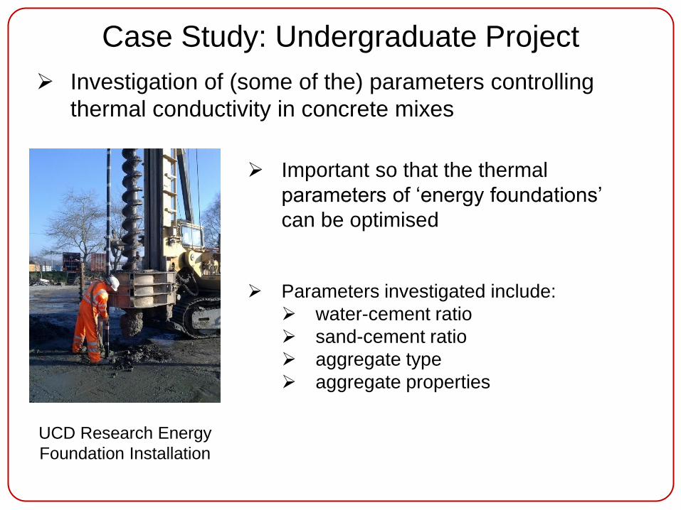
Case Study: Undergraduate Project
Investigation of (some of the) parameters controlling
thermal conductivity in concrete mixes
Important so that the thermal
parameters of ‘energy foundations’
can be optimised
Parameters investigated include:
water-cement ratio
sand-cement ratio
aggregate type
aggregate properties
UCD Research Energy
Foundation Installation

Case Study: Undergraduate Project
Sample Results: Effect of water-cement ratio
Close to linear increase in thermal
conductivity with decreasing w-c
ratio
0.0
2.0
4.0
6.0
0.2 0.3 0.4 0.5 0.6
Th
erm
al C
on
du
cti
vit
y
(W/m
K)
Water-cement (w-c) ratio
0
10
20
30
40
0.2 0.3 0.4 0.5 0.6
Co
mp
Str
en
gth
(M
Pa)
Water-cement (w-c) ratio
Concrete compressive strength also
increases with decreasing w-c ratio
This suggests that lower w-c ratios
provide higher conductivity and
higher strength However: remember that the pile
needs to be workable enough to
insert piping and ancillary
equipment - need to find the
appropriate balance

Finite Element Analysis
Research Question: If water flow is present at the site of
a proposed geothermal system, what effect on:
Interaction between boreholes on site
Neighbouring sites – future installations
Current design practice – commercial software limitations
Step 1: Develop FEM ‘conduction model’
Step 2: Verify performance
Step 3: Develop model to handle convection effects
Step 4: Compare sub-surface thermal regimes
Step 5: Develop from sub-surface to ‘holistic’ model
Step 6: Validate against installed system
Approach taken:

Finite Element Analysis
Development & performance verification of conduction
model
0.0
2.0
4.0
6.0
8.0
10.0
12.0
0 5 10 15 20 25 30
Dif
fere
nce (
%)
Time (months)
0.25m
0.50m
1.0m
2.0m3.0m
(f)
20m
20
m
Comparison against
well known radial heat
flow theory:
Small differences: radial
heat flow equation does
not take account of
borehole backfilling

Conduction Only
No g.w. Flow
Conduction & Convection
g.w. Flow = 0.16 m/day
Water Flow
Finite Element Analysis
Modelled Scenario 1:
Single borehole configuration
One month time steps
Two year time frame
Further Reading: Hemmingway, P & Tolooiyan, A. 2013. Numerical and Finite Element
Analysis of Heat Transfer in a Closed Loop Geothermal System. Intl. J. Green Energy

Conduction Only
No g.w. Flow
Conduction & Convection
g.w. Flow = 0.16 m/day
Water Flow
Finite Element Analysis
Modelled Scenario 2:
Multi borehole configuration
One month time steps
Two year time frame
Further Reading: Tolooiyan, A. & Hemmingway, P. 2012. The Effect of Groundwater Flow on
the Thermal Front Created by Borehole Heat Exchangers. lntl. J. Low-Carbon Technologies
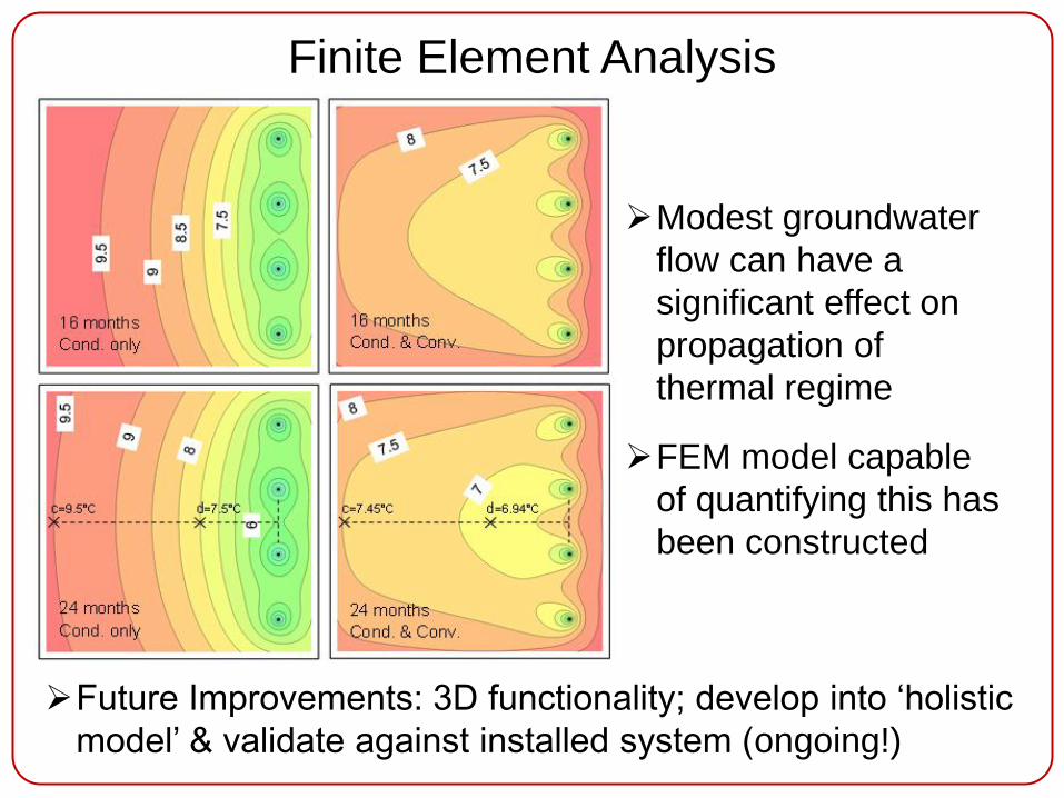
Finite Element Analysis
Modest groundwater
flow can have a
significant effect on
propagation of
thermal regime
FEM model capable
of quantifying this has
been constructed
Future Improvements: 3D functionality; develop into ‘holistic
model’ & validate against installed system (ongoing!)

Concluding Remarks
Summary of geothermal research in UCD Schools of
CSEE & Biosystems Engineering – others in UCD &
other research institutions
Current geothermal research team: Phil Hemmingway,
Mike Long, Turlough McGuinness & Tim Waters
Funding available – industry linked research
Publications available (free of charge) at:
www.ucd.ie/eacollege/biosystems/staff/academic

Thank you for your interest
Please feel free to direct any comments,
queries or collaboration enquiries to
UCD Biosystems Engineering Masters Course Enrolment - Sept 2013:
Sustainable Energy & Green Technologies
Other courses also available, please visit website:
www.ucd.ie/eacollege/biosystems