estimation of blade airloads from rotor blade bending · pdf fileestimation of blade airloads...
TRANSCRIPT

- 5 NASA Technical Memorandum 100020 d.AAVSCOM Technical Report 87-A-8
Estimation of Blade Airloads from Rotor Blade Bending Moments William G. Bousman
(UASA-Ttl-100020) E S T I H A T I O I OF BLADE ~ a 7 - 2 9 ~ 1 I A I R L O A D S PROM ROTOR BLADE BENDING MOMENTS ( N A S A ) 23 p Ava i l : N T I S HC A02/HP 801
CSCL OtA Uaclas 63/02 0 100119
August 1987
National Aeronautics and Space Administration
SYSTEMS COMMAND
AVIATION RESEARCH AND TECHNOLOGY ACTIVITY
https://ntrs.nasa.gov/search.jsp?R=19870019988 2018-05-14T04:52:11+00:00Z

NASA Technical Memorandum 100020
~ -~
USAAVSCOM Technical Report 87-A-8
Estimation of Blade Airloads from Rotor Blade Bending Moments William G. Bousman, Aeroflightdynamics Directorate, U. S. Army Aviation Research
and Technology Activity Moffett Field, California
August 1987
National Aeronautics and Space Administration
Ames Research Center Moffett Field, California 94035
US A AVlA SYSTEMS COMMAND
AVIATION RESEARCH AND TECHNOLOGY ACTIVITY MOFFETT FIELD, CA 94305-1099

ESTIMATION OF BLADE AIRLOADS FROM ROTOR BLADE BENDING MOMENTS
William G. Bousman Aeroflightdynamics Directorate
U.S. Army Aviation Research and Technology Activity Ames Research Center
Moffett Field, California 94035
1. ABSTRACT
A method is developed to estimate the blade normal airloads by using measured flap bending moments; that is, the rotor blade is used as a force balance. The blade’s ro- tating, in vacuum modes are calculated and the airloads are then expressed as an algebraic sum of the mode shapes, modal amplitudes, mass distribution, and frequency properties. The modal amplitudes are identified from the blade bending moments using the Strain Pattern Analysis Method. The application of the method is examined using simulated flap bending moment data that have been calculated from measured airloads for a full-scale rotor in a wind tunnel. The estimated airloads are compared with the wind tunnel mea- surements. The effects of the number of measurements, the number of modes, and errors in the measurements and the blade properties are examined, and the method is shown to be robust.
2. INTRODUCTION
Daughaday and Kline 111 described an approach to determining generaiized forces from measured bending moment data that assumes that, at each harmonic of rotor speed, the blade response is caused by the blade mode nearest in frequency to the harmonic. They applied this single-mode approach to flight data obtained on an H-5 helicopter with three sets of rotor blades of different stiffnesses, each of which were tested at three rotor speeds. They calculated the generalized force for each harmonic as a function of advance ratio and, although there was considerable scatter in the flight test data, they were able to demonstrate that the downwash theories that were available at that time were not able to predict the generalized forces. This was particularly noticeable at advance ratios below 0.20. They proposed that, to the extent that the generalized forces are independent of the rotor blade design, the generalized forces determined from flight test will provide a more accurate estimate of blade loading than will aerodynamic theory in the design of new rotors .
.
The possibility of using generalized forces which have been determined from flight measurements on a helicopter rotor to design a second rotor system was examined in more
6-5-1
P r e s e n t e d a t t h e T h i r t e e n t h European R o t o r c r a f t Forum, Arles France, Sept. 1987

detail by Loewy et al. [2]. They expanded on the approach of Daughaday and Kline to include an estimation of the generalized forces using the three nearest blade modes instead '
of a single mode. They calculated the generalized forces for the front rotor of an H-21 helicopter with wooden blades and applied these generalized forces to an H-21 helicopter with metal blades and to a YH-16 helicopter. The calculated bending moment data were then cornpared with available flight test measurements. The agreement was fairly good for the metal-blade H-21 rotor, but was less satisfactory for the YH-16 rotor. Loewy et al. concluded that despite the differences that were seen, there were so many similarities in the generalized forces for even disparate rotor systems and flight conditions, that the program of research should be pursued. They also concluded that the use of three adjacent modes mas an improvement over the single mode approach.
The advent of flight test data that included both surface pressure and bending mo- ment measurements (31 encouraged DuWaldt and Statler to re-examine the use of bending moment data to estimate the generalized forces (41. They treated the cosine and sine harmonics separately, and in this way, properly accounted for phase relationships which had not been done in the previous work. They compared the rotor-tip deflection that was calculated using the measured airloads with that obtained using the measured bending mo- ment data for one flight case from Reference 3. They concluded that the comparison was not Satisfactory, primarily because the methods used could not account for measurement errors.
I
Esculier and Bousman [5) have recently examined the structural response of the CH-34 rotor to the aerodynamic forces that were measured in flight and wind tunnel tests. By using the measured airloads they have been able to eliminate uncertainties in the aerodynamic model and in this way study the structural response as an isolated problem. One result of their investigation has been to show that the measurements of the airloads and the bending moments that have been obtained with the CH-34 rotor are quite accurate. An example of this is shown in Figure 1 where the 3 to 10 harmonics of the flap bending moment measured in the wind tunnel [S] are plotted in the manner of Hooper [7] using a three dimensional Cartesian surface. These are compared to the moments that have been calculated using the measured airloads. The uncoupled blade flapping equation is used for the calculation. To obtain the good agreement that is shown here it is necessary that: 1 ) the blade surface pressure measurements be accurate, 2) the blade flap equation of motion be correct, 3) the blade mass arid stiffness properties be properly computed, 4) the solution aigoritlim used to solve the differential equations be sufficiently accurate, and 5 ) t he blade bending moment measurements be correct. The good results that have been achieved with the forced response calculation shown in Figure 1 raise the question as to whether ox' not it is possible to work backwards from the bending moment measurements and calculate the spanwise airload distributions; that is, use the rotor blade as a force balance. The aerodynamic loading of helicopter rotors is still not well understood and the ability to obtain a good estimate of the spanwise normal airloads using only strain gage information would provide the experimentalist a simple and inexpensive technique to understand rotor aerodynamic behavior. This would be especially valuable if the difficult and costly problem of making accurate surface pressure measurements could be avoided.
6-5 - 2

The purpose of the present paper is to demonstrate such a technique for the estimation of the normal airloads of a helicopter blade.
3. FORMULATION
Equation of Motion
The uncoupled flapping equation of Houbolt and Brooks [8] is used to represent the blade dynamic behavior
where E I , the blade stiffness, T, the tension, and m, the mass are all functions of the blade radial coordinate. The blade displacement, w , and the normal force, F', are functions of time as well as radius. A series solution for the blade displacement is assumed which separates the time and space variables
where Qnkc and qn&# are the amplitudes of the kth cosine and sine harmonics of the nth term respectively, q5n(t) is the nth displacement shape function, and n is the rotational speed. The airload distribution is separated in a similar fashion
where Fzkc(r) and F&(t) are the cosine and sine harmonic airloads and vary with the radius. The solution is then expressed for each cosine and sine harmonic separately
As has been shown in Reference 4, if the series chosen to solve Eq. (1) is assumed to be the solution of the homogeneous form of that equation, that is, the rotating natural modes of the blade in a vacuum
6-5-3
n=l
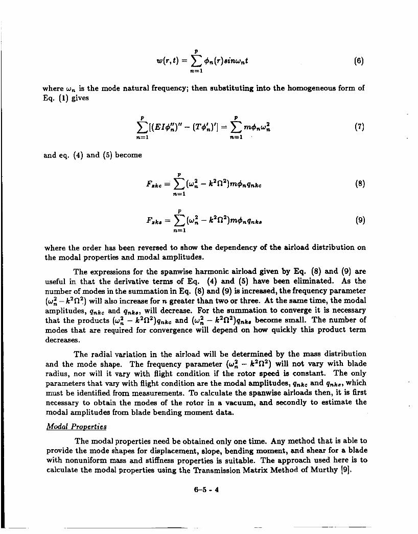
where wn is the mode natural frequency; then substituting into the homogeneous form of Eq. (1) gives
P P
n= 1 n=l
and eq. (4) and (5 ) become
n= 1
n= 1
where the order has been reversed to shaw the dependency of the airload distribution on the modal properties and modal amplitudes.
The expressions for the spanwise harmonic airload given by Eq. (8) and (9) are useful in that the derivative terms of Eq. (4) and (5) have been eliminated. As the number of modes in the summation in Eq. (8) and (9) is increased, the frequency parameter ( w i - k 2 n 2 ) will also increase for n greater than two or three. At the same time, the modal amplitudes, qnkc and Qnks, will decrease. For the summation to converge it is necessary that the products ( w i - k2n2)qnkc and (wz - k2f12)Qnka become small. The number of modes that are required for convergence will depend on how quickly this product term decreases.
The radial variation in the airload will be determined by the mass distribution and the mode shape. The frequency parameter (wz - k2f12) will not vary with blade radius, nor will it vary with flight condition if the rotor speed is constant. The only parameters that vary with flight condition are the modal amplitudes, qnkc and qnks, which must be identified from measurements. To calculate the spanwise airloads then, it is first necessary to obtain the modes of the rotor in a vacuum, and secondly to estimate the modal amplitudes from blade bending moment data.
Modal Properties
The modal properties need be obtained only one time. Any method that is able to provide the mode shapes for displacement, slope, bending moment, and shear for a blade with nonuniform mass and stiffness properties is suitable. The approach used here is to calculate the modal properties using the Transmission Matrix Method of Murthy [SI.
6-5 -4

Modal Amplitudes
The modal amplitudes are identified from blade bending moment data using a least squares fitting approach. The methodology used here follows the work of Gaukroger and his associates at the Royal Aircraft Establishment [lo, 111 referred to as the Strain Pattern Analysis Method. Their application of the method has been directed to the experimental determination of both the mode shapes and the modal amplitudes, but the approach can also be used when the mode shapes are calculated and only the modal amplitudes are determined from experimental data. The basis of the approach is that bending moment measurements at m stations are related to the modal amplitudes of p modes by
where [SI is an mxp matrix. Each column of [SI is the bending moment mode shape for the m stations and is obtained from calculation of the blade's rotating modes. For m > p the modal amplitudes can be identified by a least squares procedure
The matrix product in Eq. (ll), sometimes referred to as the [SPA] matrix, is p x m and is calculated one time.
4. APPLICATION
The method proposed here is examined for the case of a CH-34 rotor tested in a wind tunnel [6]. The procedure used is diagrammed in Figure 2. The spanwise airloads measured in the wind tunnel are used to calculate the blade state vector (displacements, slopes, bending moments, and shears) at 200 radial stations using the uncoupled forced response calculation of [5]. The calculated state vector is treated as an "exact" set of measurements. From this set of measurements bending moment "data" are interpolated for the m measurement stations. The modal amplitudes are then determined from the moment data using Eq. (11) and the spanwise airloads are calculated from Eq. (8 ) and (9). The calculated airloads are then compared to the original wind tunnel measurements as the final step. The upper path in Figure 2 is the classical forced response problem where the differential equation is solved directly. The lower path is the blade balance or inverse problem and uses a modal solution.
The CH-34 blade mass and stiffness properties used for the calculation of the modal properties have been obtained from [12] and are the same aa those used for the forced response calculation. Twelve flap modes are calculated at the nominal rotor speed of 222 rpm. It was necessary to use 31 decimal place accuracy in calculating the determinant of the Transmission Matrix for the three highest modes.
6-5-5

Modification to the Strain Pattern Andusis Method
In theory it is possible to identify the modal amplitudes from blade displacement, slope, bending moment, or shear. In practice it is difficult to measure any of these quanti- ties on a rotor in flight except the blade bending moment and, in the case of an articulated rotor, the slope at the blade hinge. The Strain Pattern Analysis Method may be applied regardless of the types of measurement that are used. For instance, if the root flapping angle is to be used as a measurement station then this is accomplished by adding an ad- ditional row to [SI using the root angle calculated for each blade mode. However, if this is done, it is necessary to normalize (or weight) the data such that the measurement for the root flapping angle is treated in an equivalent manner to the bending moment data. An alternative approach is taken here. The amplitude of the first mode, Qlkc, is initially identified on the basis of the root flapping angle. The bending moment measurements are then corrected to account for the first mode's amplitude
where me; is the moment measured at the ith station, s;l is appropriate element of the first column of [SI, and mc; is the corrected measurement. The remainder of the modal amplitudes are identified using Eq.(ll) except now the [SI does not include the first mode. The estimate of the first mode amplitude is then corrected
P
where p ( 0 ) is the root flapping angle and aln is the slope at the hinge that has been calculated for each of the p rotating modes. The process shown here is iterated upon until the change in the estimated amplitude of the first mode is less than 0.1%.
Baseline Case
The baseline case for this study assumes 20 measurement stations and 10 modes. Unless otherwise noted these values will be used for all the results to be shown. Figure 3 shows the steady (0th harmonic) spanwise airload distribution for the 150 knot, -5" shaft angle case tested in the wind tunnel. The mass distribution for this blade is discontinuous and, as this distribution is a constant factor in Eq. (8) and (9), this discontinuous vari- ation also appears in the calculated airload. It can be seen from Figure 3 that the mass concentrations along the blade coincide with the measurement stations. (The increased mass is a result of the instrumentation installation.) The airloads, of course, do not change instantaneously to reflect discontinuities in the mass distribution. For the remainder of the calculations in this paper, the mass distribution that is used in Eq. (8) and (9) is assumed constant from O.llR to the tip with a value that results in the same blade weight as the true mass distribution. The result of using this mean mass distribution is shown in Figure 3 with a dashed line.
6-5-6

The blade mode shapes all go to zero at the blade hinge point of 0.036R. The blade running mass at this point is approximately 20 times the value it takes outboard along the lifting section of the blade. An additional consequence of multiplying the blade mode shapes by the mass distribution is that, as the blade hinge is approached, the product of the mode shapes and the mass distribution sometimes result in a "tail" inboard of the blade root cutout at 0.16R even though there is no lifting surface there.
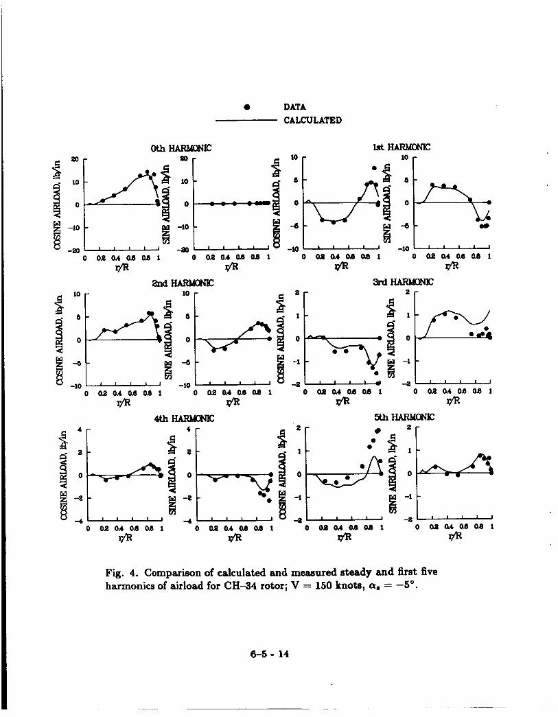
The steady and first five harmonics of airload for the 150 knot, -5" shaft angle case are shown in Figure 4. A floating scale is used for these plots so that the details of the loading may be observed. In general, the agreement between the calculation using the bending moments and the measurements is good and this is especially noticeable at the inboard stations. However, the method is unable to resolve very rapid variations in airload that are seen near the blade tip (see, for example, the 1st cosine harmonic load). In some cases, for example, the 5th cosine harmonic, disagreement is seen for nearly all of the blade stations.
The airload at the tip of the blade is, of course, zero. In most cases, the calculated airload is approaching this zero airload condition, but in some cases (for example the 3rd sine harmonic), the predicted airload has converged to a nonzero value. As will be discussed below, the airload at the blade tip is a measure of the accuracy of the summation of Eq. (8) and (9). The degree to which a zero value is achieved is a measure of how well the fitting of the measurements is done.
The agreement between the measurements and the calculations are shown as a function of blade azimuth in Figure 5 for two radial stations. The steady and first ten harmonics of the airload are shown at the top of the figure while the vibratory portion of the airload (3 to 10 harmonics) is shown at the bottom of the figure. The agreement is seen to be quite good at 0.90R, both for the full range of harmonics and for the vibratory part. This agreement is typical of all stations inboard of 0.90R. However, at 0.95R significant differences appear and the agreement is no longer satisfactory, either here or at the stations further out board.
The measurements and calculations are compared using a three-dimensional plot for the same 150 knot, -5" shaft angle case in Figure 6. This method of presentation is particularly useful in obtaining a qualitative understanding of the loading behavior of a rotor. The calculated airloads show very similar behavior over most of the rotor disk. However, near the blade tip the calculated loading is clearly reduced compared to the measurements. The calculated nonzero airload is particularly noticeable with this type of plot.
Detailed measurements were obtained by Rabbott et al. [6] for ten combinations of airspeed and shaft angle. In general, the agreement that has been shown for the 150 knot, -5" shaft angle condition was observed for the other test conditions as well. Two examples are shown in Figure 7 for the airloads at 0.90R. Figure 7(a) shows the 110 knot, -9" shaft angle case which corresponds most closely to the flight test cases reported by Scheiman [3]. Figure 7(b) shows the 175 knot, 0" shaft angle case which appears to be the
6-5-7

most severely loaded case tested in the wind tunnel. Both cases show good agreement for this station and this agreement is typical of the inboard stations as well.
The airload at the blade tip must be zero as was noted above. For the cosine harmonic airload at the tip
where all the mode displacements are normalized to one at the tip. The degree to which this summation approaches zero for each harmonic airload is a measure of how well the measurements have been fitted. The behavior of this summation as the number of terms is increased is examined in Figure 8 for four of the harmonic airloads shown previously in Figure 4. The first harmonic airloads appear to be converging to a nonzero value although this is not completely clear. The third harmonic airloads, on the other hand, have clearly converged to a nonzero tip airload. It appears that only errors in fitting the first or second modes can explain the differences that are seen here. The modal amplitudes have been identified here using the root flapping angle and bending moment measurements. Although this provides a good estimate of the blade airloads out to 0.90R, the summation in Figure 8 suggests that if the known boundary condition of zero lift at the blade tip were enforced during the identification process an improved estimate of the blade airloads could be achieved.
Effect of Number of Modes
Airloads were calculated for the CH-34 rotor assuming 20 measurement stations and using a variable number of modes from 4 to 12. In general, the predicted airloads were not strongly affected even when only four flapping modes were used. The 3rd harmonic airloads show the largest differences for the 150 knot, -5" shaft angle case. These are shown in Figure 9 for 4, 8, and 12 modes. Some improvement is seen in going from 4 to 8 modes, although even the four mode fit gives a reasonable approximation of the loading. Little effect is seen in going from 8 to 12 modes except for the 3rd cosine airload near the blade tip where a better fit is achieved. In this latter case the modal fit appears to show behavior similar to a Fourier series representation of a time history; that is, the more irregular the behavior the more terms (modes) that are required in the series.
Effect of Measurement Error and Number of Measurement Stations The number of measurement stations must be equal to or greater than the number
of modes for the identification of the modal amplitudes. For error-free data, there is little difference whether the number of measurement stations is the same as the number of modes or twice the number. When errors are introduced into the data, however, redundancy in the number of measurement stations shows some improvement in the calculation. Three types of error will occur in normal experimental measurements on a rotor blade of the kind discussed here. The measurement at station r is expressed
6-5 -8

where h(t,t) is the true value of the parameter measured. The error c l ( t ) is a calibration or scale error and will vary for each measurement station along the blade. It will influence all harmonic load calculations. The error ~ ( r ) represents a static or zero offset error and this will only influence the calculation of the steady airload. The final error, ~ ( t ) , represents random errors distributed in time and it is assumed that these errors may be reduced by averaging.
The effect of calibration errors in the measurements is evaluated by assuming that f5% errors are distributed randomly over the various measurement stations. Figure 10 shows the 3rd harmonic airload for the 150 knot, -5" shaft angle case for 10, 14, and 20 measurement stations and a 3 ~ 5 % error. Ten modes were used for these calculations. In general, the effect of errors of this size was small and the 3rd cosine harmonic airload shown here is typical of most of the cases. The 3rd sine harmonic airload shown in Figure 10 represents the greatest variation that was seen and it is not obvious that the calculation using the most measurement stations gives the best results. The airload at 0.90R is shown in Figure 11 for this same case and it is seen that the effect of errors of this size is slight. These results show that the method used here is relatively insensitive to errors that may be expected to occur in a carefully performed experiment, and this is encouraging.
Effect of Chanaes in M u s and Stiffness Properties
Detailed measurements to identify the rotating modal frequencies of a full-scale rotor are not often made, but often the frequencies of the actual rotor are lower than the predicted values either because of slight mass increases or stiffness decreases in construc- tion, or both. To study this effect here it is assumed that the simulated bending moment data represent the actual measurements and the airloads are calculated using: (1) rotor properties that are 5% stiffer, or (2) properties with 5% lower mass. These calculations are shown in Figure 12 for the 150 knot, -5' shaft angle case for the 8th harmonic airload. In most cases, the effects of mass and stiffness differences are slight as is seen for the 8th sine airload. In the case of the 8th cosine airload, the 5% mass and stiffness changes show an observable effect, but this effect is not large. The airload calculation method proposed here is, in general, insensitive to the small differences in mass and stiffness properties that may be expected between design values and actual hardware.
5. CALCULATION OF ROOT SHEARS
Once the modal amplitudes have been calculated, it is possible to obtain any of the state vector properties along the blade, not just the displacements that have been used here to estimate the blade airloads. Thus, the same methodology can be used to identify the root shears which are important in understanding the vibratory loading of the fuselage. This approach or a similar one has been used in the past by numerous investigators to identify the blade root shears using blade bending moment data [13-151. As an example, the modal amplitudes that have been used in this paper to calculate the airload distribution can also be used to estimate the blade root shears and these can be compared with the original state vector values. This is shown in Figure 13 for the absolute value of 1 to 5
6-5-9

harmonics of blade root shear for all 10 of the cases of Rabbott et d. [6]. As can be seen, the root shears are calculated accurately.
6. ADDITIONAL CONSIDERATIONS
The computation of the spanwise distribution of the airloads from bending moment measurements that has been demonstrated here essentially requires two steps. First, it is necessary to compute the properties of the rotating modes of a rotor in a vacuum, and secondly, it is necessary to idefitify the modal amplitudes. The modal frequencies and displacement mode shapes required by Eq. (8) and (9) need only be obtained once unless multiple rotor speed cases are being examined. Similarly, the matrix algebra based on the [SI matrix required to calculate the modal amplitudes using Eq. (11) is done only one time. Both of these computations are straighforward and to some degree are done for other purposes during the development of any new rotor system. The method proposed here does not add any significant computational requirements.
The success of the method shown bere is believed to be due in part to the fact that the blade normal airloads are much greater than the chordwise airloads or the blade pitching moments and that the blade stiffness is much less in flapping than in either chord or torsion. Thus, both of these degrees of freedom can be neglected in estimating the normal forces on the blade. However, it is believed that any attempt to estimate chordwise airloads from chord bending moment measurements will be a much more difficult task and require the solution of the coupled blade equations. The estimation of blade pitching moments from torsional measurements should, be a less formidable task.
7 . CONCLUSIONS
A method of estimating the spanwise airloads of a rotor using blade bending mo- ment measuements has been evaluated. Measured airloads from a test of a CH-34 rotor in a wind tunnel have been used as the input to the forced response flapping equation to solve for simulated bending moments. The rotor response is assumed to be a summation of rotating modes and the modal amplitudes are identified using a least squares fitting procedure. The spanwise airload distribution is then calculated using a modal solution of the flap equation of motion.
The method has been examined by comparing the airload distribution that is calculated from the modal solution with the original wind tunnel measurements using 10 modes and 20 measurement stations. The predicted airloads show good agreement with the measurements out to O.WR, but the agreement degrades towards the blade tip.
The effect of varying the number of modes used in the fitting process is evalu- ated for the wind tunnel data and it is shown that an increase in the number of modes used improves the fit, particularly near the blade tip. However, beyond eight modes this improvement is slight.
6-5 - 10

The effect of errors in the data is examined by assuming a random distribution of calibration errors at the various measurement stations. It is shown that some improve- ment in predictive capability is obtained with measurement redundancy, but, in general, the method is tolerant of errors of the size that can be expected in carefully performed experiments .
Finally, the method is evaluated for differences in mass and stiffness properties that might realistically be expected between calculated values and the actual rotor properties. The predicted airloads are insensitive to changes of the order of 5% in mass or stiffness.
The method proposed here is shown to be quite robust to the sorts of experimental problems that could be expected to occur in the testing of a full-scale or model-scale rotor. It is shown that the computational requirements for applying the method are the same or similar to computations that are normally performed during the design of a rotor system.
8. ACKNOWLEDGEMENT
The work reported here was performed while the author was a visiting scien- tist in the Structures Department, Office Nationale d’Etudes et Recherches Aerospatiales, Chiitillon, France under the auspices of the U.S./France MOU for a Cooperative Research Project in Helicopter Dynamics.. I wish to acknowledge my many colleagues at ONERA for providing me the working environment that allowed this work to come to fruition.
9. REFERENCES
1. H. Daughaday and J. Kline, An approach to the determination of higher harmonic
2. Robert G. Loewy, Harry Sternfeld, Jr., and Robert H. Spencer, Evaluation of rotor blade generalized forces as determined from flight strain data, WADD Technical Re- port 59-24, Feb 1960.
and motions as measured in flight, NASA TM X-952, Mar 1964.
blade stresses, C.A.L. 52, Mar 1953.
3. James Scheiman, A tabulation of helicopter rotor-blade differential pressures, stresses,
4. F. A. DuWaldt and I. C. Statler, Derivation of rotor blade generalized air loads from measured flapwise bending moment and measured pressure distributions, USAAVLABS TR 66-13, Mar 1966.
5. Jacques Esculier and William G. Bousman, Calculated and measured blade structural response on a full-scale rotor, American Helicopter Society 42nd Annual Forum Pro- ceedings, Jun 1986, pp. 81-110.
6. J. P. Rabbott Jr., A. A. Lizak, and V. M. Paglino, A presentation of measured and calcu- lated full-scale rotor blade aerodynamic and structural loads, USAAVLABS TR 66-31, Jul 1966.
6-5 - 11

7. W. E. Hooper, The vibratory airloading of helicopter rotors, Vertica, 8, 1984, pp. 71-92.
8. John C. Houbolt and George W. Brooks, Differential equations of motion for combined flapwise bending, chordwise bending, and torsion of twisted nonuniform rotor blades, NACA Report 1346, 1958.
9. V. R. Murthy, Dynamic characteristics of rotor blades, Journal of Sound and Vibration, Vol. 49, NO. 4, D ~ C 1976, pp. 483-500.
10. D. R. Gaukroger and G. J. W. Hassal, Measurement of vibratory displacements of a rotating blade, Vertica, 2, 1978, pp. 111-120.
11. D. R. Gaukroger, D. B. Payen, and A. R. Walker, Application of strain gauge pattern analysis, Paper No. 19, Sixth European Rotorcraft and Powered Lift Aircraft Forum, Sep 1980.
12. Charles F. Niebanck, Model rotor test data for verification of blade response and rotor performance calculations, USAAMRDL TR 74-29, May 1974.
13. K. T. McKenzie and D. A. S. Howell, The prediction of loading actions on high speed semirigid rotor helicopters, AGARD Conf. Proc. No. 122, Mar 1973.
14. Robert B. Taylor and Paul A. Teare, Helicopter vibration reduction with pendulum absorbers, Journal of the American Helicopter Society, vol. 20, no. 3, Jul 1975, pp. 9-17.
15. R. H. Blackwell, Jr., Blade design for reduced helicopter vibration, Journal of the American Helicopter Society, vol. 28, no. 3, Jul 1983, pp. 33-41.
Fig. 1. Comparison of flap bending moments for 3 to 10 harmonics on a CH-34 rotor; V = 150 knots, a, = -5O. (a) Measured flap bending moments from Reference 6. (b) Calculated flap bending moments using measured airloads [ 51.
6-5 - 12

MEASUR ED AIRLOADS
4
1 * FORCED RESPONSE CALCULATED STATE CALCULATION VECTOR
J
Fig. 2. Diagram of calculation process.
ROTOR MASS/STIFFNESS PROPERTIES
,
20 - c a 0 DATA d ACTUAL MASS DISTRIBUTION
q 15 -
MEAN MASS DISTRIBUTION ---------- 3 l o - E 5 - 4
0 , -
CALCULATED MODAL * AIRLOADS SOLUTION
0 0.2 0.4 0.6 0.8 1
r/R
* , CALCULATED STATE VECTOR
Fig. 3. Comparison of calculated and measured steady (0th har- monic) airload for CH-34 rotor; V = 150 knots; CY* = -5".
6-5 - 13
0 DATA CALCULATED
r
lo 0 L-4 lo
6
0
-10 - 0 0 2 0 . 4 W 0 . 0 1
6b 0
-10
- -10 - 0 0 8 o A o b o a l 0 02 a4 OB OB 1
p?z f l 3 N l " E
r 2 r
I B
0 O a o A a s O B 1 g/R
0
-I t
Fig. 4. Comparison of calculated and measured steady and first five harmonics of airload for CH-34 rotor; V = 150 knots, a, = -5".
6-5 - 14

DATA CALCULATED
-10 ' 1 1 I I I I 1 1
0 4 s 9 0 1 3 6 1 m 2 3 6 R o 3 l s ~ -10 1 I 1 1 I I I
0 16 90 135 180 m 210 315 90 BLADEAzcMuTH,deg
90
80
10
0
-10 (4 I I I
1 1 I I
Fig. 5. Comparison of calculated and measured time histories of airload for CH-34 rotor; V = 150 knots, a, = -5'. (a) r/R = 0.90, 0 to 10 harmonics. (b) r/R = 0.95,O to 10 harmonics. (c) r/R = 0.90, 3 to 10 harmonics. (d) r/R = 0.95,3 to 10 harmonics.
6-5- 15

Fig. 6. Cartesian plots of CH-34 calculated and measured airloads; V = 150 knots, a, = -5". (a) wind tunnel measurements, 0 to 10 harmonics. (b) calculated, 0 to 10 harmonics. (c) wind tunnel mea- surements, 3 to 10 harmonics. (d) calculated, 3 to 10 harmonics.
6-5- 16

" r * r 30
-20
-30
- ca)
I 1 I 1 I I I
0 4 6 9 0 1 3 6 1 m ~ 4 E o 9 1 6 9 d o B=-@
Fig. 7. Comparison of calculated and measured time histories of airload for CH-34 rotor; r/R = 0.90,O to 10 harmonics. (a) V = 110 knots, cy. = -go. (b) V = 175 knots, cy, = 0".
c.
I 3rd SINE
Y \
I I I I 1
I I 1 1 1 I
0 2 4 6 8 10 12 MODE NUMBER
Fig. 8. Calculated tip airload with increasing terms of summation.
6-5 - 17

2 0 DATA p = 12, m = 20
---------- p = 8, m = 20 -.-.
1 p = 4, m = 20
E
d -
3 0
i2 -1
s e w
0
1 I I I 4 -2 1 1 I I I
Fig. 9. Effect of the number of modes on the 3rd harmonic airloads for the CH-34 rotor; V = 150 knots, a, = -5O.
0 DATA m = 20.51: error m = 14.51: error ---------- m = 10,51: error -.-.
3 E
E e W
VI 8
0
-2 0 0.2 0.4 0.6 0.8 1
r/R
-2 0 0.2 0.4 0.0 0.0 1
rm
Fig. 10. Effect of measurement error on the 3rd harmonic airload for different numbers of measurement stations for the CH-34 rotor; V = 150 knots, a, = -5".
6-5 - 18

20 E:
2i 10
3 0
-10 0
0.75
0.50
0.25 d
E
4
3 0.00
8
e W
-0.25
DATA m = 20.5% error m = 14, 5 X error m = 10,5X error
- - - - - - - - - - -.-.
-
4 0
.. -10 I I I 1 1 I I I
Fig. 11. Effect of measurement error on time history at 0.90R for CH-34 rotor; V = 150 knot, a, = -5O. (a) 0 to 10 harmonics. (b) 3 to 10 harmonics.
0 DATA CH-34 PROPERTIES S X STIFFNESS INCR. 5% MASS DECR.
---------- -.-.
.'*.
-OsM) t -0.75 I I I I I I
0 0.2 0.4 Ob 0.8 1
r/R
0.75
0.50
c 3 0.25
d 4 3 0.00
E 4
-0.25 v)
4 3 0.00
-4 -0.25 E
v)
0
-0.60
-0.75 0 0.2 0.4 0.6 0.0 1
r/R
Fig. 12. Effect of 5% change in mass and stiffness properties on 8th harmonic airload for CH-34 rotor; V = 150 knots; a, = -5".
6-5 - 19

loo0 800 1 8oo 400 t
0
e 8 e
e E
e
0 200 400 600 800 1000
MEASURED SHEAR, lb
Fig. 13. Root flapping shears for harmonics 1 to 5 calculated from “measured” bending moment data compared to “measured” shears for CH-34 rotor.
6-5 - 20

Report Documentation Page
I . Report No. NASA TM 100020 USAAVSCOM TR-87-A-8
2. Government Accession No. 3. Recipient's Catalog No.
-
Estimation of Blade Airloads from Rotor Blade Bending Moments
4. Title and Subtitle
August 1987 _-
6. Performing Organization Code
5. Report Date
7. Authods)
William G. Bousman
8. Performing Organization Report No.
A-87311 10. Work Unit No.
9. Performing Organization Name and Address Aeroflightdynamics Directorate, U.S. Army Aviation Research and Technology Activity Ames Research Center Moffett Field, CA 94035
992-2 1-01 11. Contract or Grant No.
13. Type of Report and Period Covered
2. Sponsoring Agency Name and Address National Aeronautics and Space Administration Technical Memorandum
Point of contact: William G. Bousman, Ames Research Center, MS 215-1, Moffett Field, CA 94035 (415)694-5850 or FTS 464-5850
Washington, D.C. 20546 United States Army Aviation Systems Command St. Louis, Missouri 63120 e
16. Abstract A method is developed to estimate the blade normal airloads by using measured
flap bending moments; that is, the rotor blade is used as a force balance. The blade's rotating, in vacuum modes are calculated and the airloads are then expressed as an algebraic sum of the mode shapes, modal amplitudes, mass distri- bution, and frequency properties. The modal amplitudes are identified from the blade bending moments using the Strain Pattern Analysis Method. The application of the method is examined using simulated flap bending moment data that have been calculated from measured airloads for a full-scale rotor in a wind tunnel. The estimated airloads are compared with the wind tunnel measurements. The effects of the number of measurements, the number of modes, and errors in the measurements and the blade properties are examined, and the method is shown to be robust.
14. Sponsoring Agency Code
17. Key Words (Suggested by Authods))
Rotor loads Blade airloads Bending moment measurements
18. Distribution Statement
Unlimited - Unclassified
Subject Category: 02
20. Security Classif. (of this page) 21. No. of pages 19. Security Classif. (of this report)
Unclassified Unclassified 22
22. Price
A0 2