estimation of minimum cost design of circular grain …
TRANSCRIPT

Tikrit Journal of Eng. Sciences/Vol.12/No.4/November/2005
ESTIMATION OF MINIMUM COST
DESIGN OF CIRCULAR GRAIN SILO
Hasan Jasim Mohammad Al-Badri
M.Sc. Structure / Engineering collage- Tikreet University
ABSTRACT
This study is an application of optimization method to the
structural design of circular silo, considering the total cost of the
silo as an objective function of the properties of the silo and
stored materials (unit weight of stored materials, angle of
inclination of hopper wall, height of silo, height of hopper and
silo diameter), as a design variables.
A computer program has been written to solve numerical
examples using the ACI code equations and all new requirements
and criteria in concrete design.
It has been proved that the minimum total cost of the silo
increases with the increase of the angle of internal friction
between stored materials, the coefficient of friction between
stored materials and concrete, and the number of columns
supporting hopper.
KEYWORDS
Optimization, structural design, ACI code
(22-51) 22

Tikrit Journal of Eng. Sciences/Vol.12/No.4/November/2005
NOTATIONS Ar area of cross section of ring beam
As reinforcement steel area (per unit width of wall)
Cd overpressure factor, for static pressures to design pressures
D inside diameter (unless noted)
Es,Ec modulus of elasticity for steel and concrete ,respectively
Fm meridian membrane force per unit width of hopper wall
Ft horizontal membrane force per unit width of hopper wall
fy yield strength of steel
H height of silo
HA shear in ring beams at face of columns
I moment of inertia
L perimeter of inside cross section
M bending moment , per unit width of wall
P horizontal static pressure due to stored material
R hydraulic radius of horizontal cross section of storage space
Vu ultimate shear force
W total weight of stored material
Y depth from surface of stored material to design point
des a subscript indicating ‘design ‘ force or pressure
fc,vert vertical compressive stress at wall bottom
fc ultimate compressive strength of concrete
fs steel stress ,tension
hc height of column
L.L. a subscript meaning ‘live load’
(23-51) 23

Tikrit Journal of Eng. Sciences/Vol.12/No.4/November/2005
m shrinkage coefficient ,generally 0.0003
n modular ratio ,Es/Ec
q static vertical pressure due to stored material
q unit static pressure normal to a surface inclined at angle
angle of inclination of hopper wall
unit weight of stored material
coefficient of friction between stored material and wall
=tan
angle of internal friction
capacity reduction factor
INTRODUCTION
Bins for storing granular materials are of two main types
silos (also called deep bins), and bunkers (or shallow bins). The
important difference between the two is in the behavior of the
stored materials. This behavior difference is influenced by both
bin geometry and characteristics of the stored material. Material
pressures against the walls at bottom are usually determined by
one method for silos and by another for bunkers. Silos and bunkers are made from many different structural
materials. Of these, concrete is probably the most frequently
used. Concrete can offer the necessary protection to the stored
materials, requires little maintenance, is aesthetically pleasing,
and is relatively free of certain structural hazards, which may be
present in silos or bunkers of thinner materials.
(24-51) 24

Tikrit Journal of Eng. Sciences/Vol.12/No.4/November/2005
Silos and bunkers may be of various plan shapes and may
occur singly or connected in-groups. See Figures (1,2)[1].
PURPOSE OF STUDY
The purpose of this study is to detect the capabilities of
optimization method to handle the economical structural design
of a circular grain silo, giving a safe design based on considering
the effects of different parameters on the silo cost and giving the
designer the relationships and curves between variables of design
so that the design of a circular grain silo can be more reliable and
simple.
HISTORICAL BACKGROUND
Torres et al., (1966) presented the minimum cost design of
prestressed concrete highway bridges subjected to AASHTO
loading by using piecewise LP method [2].
Kirsch (1972) presented minimum cost of a continuous two-
span prestressed concrete beam .The cost function included only
cost of concrete and cost of prestressing steel [3].
Namman (1982) presented minimum cost design of
prestressed concrete tensile member based on the ACI-Code
1977 .The cost function includes the material costs of concrete
and the prestressing steel [4].
Al-Jubair (1994) minimized the cost of ring foundations by
using simplex method of Nelder and Mead. The results obtained
(25-51) 25

Tikrit Journal of Eng. Sciences/Vol.12/No.4/November/2005
supported the efficiency of optimization techniques in selecting
the most economical design of ring foundations for given
conditions [5].
Al-Douri (1999) minimized the cost of rectangular combined
footings by using several methods .She concluded that the
minimum cost of the footing decreases with increasing the
distance between the columns for a constant length [6].
Al-Jubori (2001) minimized the cost design of mat
foundations .He proved that the minimum cost of the raft
foundation decreases with increasing of the angle of internal
friction of soil and increases with increasing the column spacing
in both directions as well as with increasing the difference
between the loads of adjacent columns[2].
OBJECTIVE FUNCTION
The total cost of silo can be represented by:
ZT=CSRE+CSFW+CSCO …………….…………(1)
Where:
ZT= total cost (unit price).
CSRE= cost of silo reinforcement (unit price).
CSFW= cost of silo formwork (unit price).
CSCO= cost of silo concrete (unit price).
CSRE= TOTRE*COR
={πDH [(1/SPSav)+(1/SPSsv)]+Ash }*COR ……(2)
(26-51) 26

Tikrit Journal of Eng. Sciences/Vol.12/No.4/November/2005
CSFW= Awohle*COFW
= {πD H * 2+πD (Hh sin)}*COFW ...……(3)
CSCO= Vwohle*COCO
= {Awohle *t+Vco}* COCO ...……(4)
Where:
TOTRE= Total weight of reinforcement steel (Ton)
COR= Price of reinforcement (unit price/Ton)
COFW= Price of formwork (unit price/m2)
COCO= Price of concrete (unit price/m3)
D, H , Hh, t = Silo diameter , height , hopper height ,and
thickness of wall ,respectively.
SPSav, SPSsv = Average Spacing between horizontal steel,
and that between vertical steel , respectively.
Ash= Amount of hopper reinforcement.
Vco= Volume of columns concrete.
PROPERTIES OF STORED MATERIALS
The properties of material to be stored affect the intensity of
loading pressure, in addition, they influence on material flow and
must be considered in selecting the outlet shape and size and the
type of unloading system. ACI 313R-97, Table 4-A[7] , suggests
stored material properties. Here in shown in table (1).
(27-51) 27
Tikrit Journal of Eng. Sciences/Vol.12/No.4/November/2005
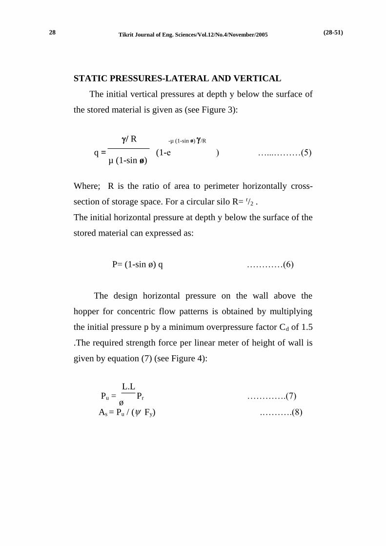
STATIC PRESSURES-LATERAL AND VERTICAL
The initial vertical pressures at depth y below the surface of
the stored material is given as (see Figure 3):
/ R -µ (1-sin ø) /R
q = (1-e ) …...………(5) µ (1-sin ø)
Where; R is the ratio of area to perimeter horizontally cross-
section of storage space. For a circular silo R= r/2 .
The initial horizontal pressure at depth y below the surface of the
stored material can expressed as:
P= (1-sin ø) q …………(6)
The design horizontal pressure on the wall above the
hopper for concentric flow patterns is obtained by multiplying
the initial pressure p by a minimum overpressure factor Cd of 1.5
.The required strength force per linear meter of height of wall is
given by equation (7) (see Figure 4):
L.L Pu = Pr ………….(7) ø As = Pu / ( Fy) .……….(8)
(28-51) 28

Tikrit Journal of Eng. Sciences/Vol.12/No.4/November/2005
Where L.L =1.6 is a factor of safety for live load (ACI 318-02)[7],
and ø = 0.9 is the strength reduction factor for axial tension as
suggested by ACI 318-02.
The term static pressure applies only, for stored material at
rest (i.e., before withdrawal is begin). During withdrawal, these
pressures may increase. The increases are sometimes called
dynamic effects, but the term "overpressure" is preferred since
the increases include both static and dynamic effects. However,
its effect can be approximated using overpressure factor Cd, to
convert from computed static pressure to designed pressure. In
general.
Design pressure = Cd * static pressure ………. (9)
For silos with centrally located discharge opening, design
pressures due to stored material are:
qdes = Cd q ……...….(10)
Pdes = Cd P …...……..(11)
q,des = Pdes sin2 + qdes cos2 …...……..(12)
Conical Hopper
The design pressure, q,des may be computed from Eq (12).
The conical hopper shell is subjected to two tensile membrane
forces. The meridian force, Fm, is parallel to the generator line of
(29-51) 29

Tikrit Journal of Eng. Sciences/Vol.12/No.4/November/2005
the cone. The tangential force, Ft, is in the plane of the shell and
horizontal. These forces, shown in Fig. (5), are the resultant of
vertical pressures, qdes (at depth Y) and W, the combined weights
of the hopper itself and material stored below depth Y plus any
equipment supported by the hopper.
qdes Dav. W
Fmu = L.L + ….….....(13) 4sin Dav. 4sin
q ,des D
Ftu = L.L …...…….(14) 2sin
The required reinforcement area per unit width of shell is:
As reqd = Fmu / ( fy) (meridian direction) ……..(15)
As reqd = Ftu / ( fy) (horizontal) ……...(16)
A conical hopper is usually supported at its upper end by a
ring beam. The depth of the ring beam should not be less than
one-tenth of hopper diameter. See Fig. (6).
Wall Thickness
An isolated circular silo under uniform radial load gets its
strength from the horizontal steel wherever the concrete is
cracked. One approach is the PCA formula, Eq. (17) below:
(30-51) 30

Tikrit Journal of Eng. Sciences/Vol.12/No.4/November/2005
mEs+ fs-nfc΄,ten
hmin = P D/2 ………(17) fs fc,ten
In this equation, PCA suggests using 0.1fc΄ for allowable
stress fc΄,ten .Vertical compressive stresses should also be checked.
Suggested limits for circular silos are
fc,vert = 0.385 fc΄ where, fc΄ in MPa …….…(18)
Crack Control
Wall thickness and reinforcement have to be so proportioned
that, under pressure, the design crack width Wc computed using
formula (19) shall not exceed 0.25 mm [7]:
Wc = 0.0001 fs [dc A]1/3 (0.145) 0.25 mm ..(19)
Where fs in (MPa) represents the calculated stress in
reinforcement steel at initial pressures, and dc and A are
expressed as follows;
dc=2.5db ……………. (20) A=2dc s
Where db is the diameter of the horizontal steel bars.
Ring Beam and Columns Supporting a Hopper
The concrete ring beam must be designed to carry all loads
including torsion moments. The external design loads acting on
(31-51) 31

Tikrit Journal of Eng. Sciences/Vol.12/No.4/November/2005
the ring beam (shown in Fig. 7-9) are approximately calculated
as;
Fx = Fmu cosα /1.6 …………(21)
Fy=gr+Fmu sinα /1.6 …………(22)
Where: gr is the self-weight of ring beam per unit length.
Mt=Fmu e (N.m/linear m) ………….(23)
Coordinates of the centroid measured from origin O are:
x¯ =(a1b12/2 - (a2 b2/2)(b1-b2 /3))/Ar ……………..(24)
y¯ = (a12b1/2 - (a2 b2/2)(a1-a2 /3))/Ar ……………..(25)
An equivalent rectangle (shown dotted in Fig. 9) of height 'a'and
width 'b' is substituted for the pentagon:
.
a= 2 y¯ b= Ar/a ………….(26,27)
The column shear, HA, and upper end moment, MA, are found by
solving simultaneously Eqs. (29) and (30):
Fxr2/Ar = MA[h2c/2Ic]-HA[h3
c/3Ic+ η r3/2Ir] ….(28)
(32-51) 32

Tikrit Journal of Eng. Sciences/Vol.12/No.4/November/2005
12Mt r/a3 ln(r2/r1) = MA[hc/Ic + л r z/(6.8b4λ)]
-HA[h2c/2Ic] …….(29)
Where η and z are numerical coefficients and λ is a torsional
property of the equivalent rectangular section [8].
MB=HAhc-MA (30)
The cross sectional area of ring beam is: Ar=a1b1-b2a2/2 ....(31)
COMPUTER PROGRAM
The main program was utilized to perform the necessary
calculations for optimization was drawn from Bundy (1984) [9]
and translated to FORTRAN-77.Hooke and Jeeves method
performed the minimization process utilizing this method of
solution. Following are the required input parameters for this
program.
Ns- number of independent (design) variables.
X(Iz)-initial estimate of the design variables [Iz=1,2,3,……Ns]
Hz-step length.
The program (Silo. For) in FORTRAN-77 is written by using
the design procedure of ACI-Code with code improvement in
load factors and crack width equation [7]. This program gave
good results with code requirements and other design criteria.
The program (Silo. For) use a subroutine with the program
(H & J. For). Input data symbols and other parameters used in
(33-51) 33

Tikrit Journal of Eng. Sciences/Vol.12/No.4/November/2005
subroutine (Silo. For) is listed in table (2) and results shown in
table (3).
Numerical Example
The basic data of the problem is shown in Fig. (10) .The
problem was solved using three initial trial values for design
variables vector X=[,, H, HH, D] .The input data is Ns=5
The first initial trial values: X(1)=9 , X(2)=45 , X(3)=35 , X(4)=7
, X(5)=11. The second initial trial values: X(1)=8 , X(2)=60 ,
X(3)=40 , X(4)=9 , X(5)=12 .The third initial trial values: X(1)=7
, X(2)=50 , X(3)=30 , X(4)=8 , X(5)=10 .
Hz=0.01
The results obtained are shown in table (4). Figs (11-13)
show the convergence rate towards the minimum cost design of
circular grain silo.
DISCUSSION OF RESULTS
A parametric study was done to the angle of internal friction
of the stored material, coefficient of friction between stored
material and concrete wall and the number of columns supporting
conical hopper for the first initial trial point. The results are listed
in tables (5,6,7).
It can be observed from table (5) and Figs. (14-19) and Fig.
(28) that as the angle of internal friction increases; the minimum
total cost is increased, Fig (14). The increase is noticed after
angle value of 30˚, and minimum total cost is at 25˚. The
(34-51) 34

Tikrit Journal of Eng. Sciences/Vol.12/No.4/November/2005
optimum unit weight is slightly decrease after angle 30˚, Fig.
(15). The optimum hopper angle, silo height and hopper height
are increased after the angle of 30˚, Figs. (16,17,18). The
maximum crack width remains constant and later slightly
decreases after the angle was 30˚, Fig. (19). The optimum silo
diameter increases after the angle was 30˚, Fig. (28). So, from the
obtained results it is concluded that the optimum angle of internal
friction is 25˚.
It can be observed from table (6) and Figs (20-25) that as the
coefficient of friction between stored material and concrete wall
increases; the minimum total cost rapidly increased Fig. (20).
The optimum hopper angle, silo height, silo diameter and hopper
height also slightly increased, Figs. (22-25). But the optimum
unit weight is little change, Fig. (21).
It can be realized from table (7) and Figs (26,27) that as the
number of columns supporting conical hopper increase; the
minimum total cost is approximately remain constant, but
increased when the number of columns is twelve or more. The
optimum hopper height and silo diameter slightly decreases when
the number of columns increases. The other variables still
constant when the number of columns increases.
CONCLUSIONS
1-The economical structural silo design can be handled as a
problem of mathematical programming.
(35-51) 35

Tikrit Journal of Eng. Sciences/Vol.12/No.4/November/2005
2-Optimization techniques were powerful applied to the optimum
structural silo design.
3-The minimum total cost was more sensitive to the changes in
angle of internal friction between stored materials and
coefficient of friction between stored materials and concrete
wall.
4-Increase in angle of internal friction leads to increase
minimum total cost , hopper height, silo height, hopper angle
and silo diameter. This increase effects as Little decrease in
unit weight of stored materials and maximum crack width.
Optimum angle of internal friction is 25˚.
5-Increase in coefficient of friction leads to increase minimum
total cost , hopper angle , silo height, hopper height and silo
diameter . So , little changes are obtained in unit weight of
stored materials.
6-Increase in number of supporting columns of conical hopper
leads to increase total cost and silo diameter .
REFERENCES
1-Fintel , M. ‘’ Handbook of Concrete Engineering ’’, Litton
Educational Publishers (1974).
2-Al-Jubori , A. M. , “ Optimum Design of Raft Foundations ”
,M.Sc. Thesis ,Tikrit University , College of Engineering, Civil
Department (2001).
3 -Kirsch , U. “ Optimum Design of Prestressed Beams “,
(36-51) 36

Tikrit Journal of Eng. Sciences/Vol.12/No.4/November/2005
Computer and Structure , Vol.2No.4 , pp. 573-583 (1972) .
4-Naaman , A. E. , “ Optimum Design of Prestressed Concrete
Tension Members ” , ASCE , Vol.108 , No. 8 ,pp. 1722-1738
(1982).
5-Al-Jubair, H.S. , ’’ Economical Design of Ring Foundations ‘’
Al-Muhandis J. S.S. ,vol.120,No.4, pp.45-54(1994).
6-Al- Douri , E . M. ,’’ Optimum Design of Rectangular
Combined Footings’’ ,M.Sc. Thesis, Tikrit University (1999).
7-Vector Con . Group “ Grain Silo Strengthening - South
Dakota”, Prepared for Vector Construction Group (2002).
8-Carson , J. W. and Jenkyn , R.T. ,’’ Load Development and
Structural Considerations in Silo Design “ , Jenike & Johanson
In. (1993).
9-Bundy , B. D. , ’’ Basic Optimization Methods ‘ , Edward
Arnold Publishers (1984).
10-ACI Committee 318-89,’’ Building Code Requirements for
Reinforced Concrete’’, ACI Detroit (1989).
11-ACI Committee 313-97, ’’ Building Code Requirements for
Reinforced Concrete’’ ,ACI Detroit (1997).
12-ACI Committee 318-99, ’’ Building Code Requirements for
Reinforced Concrete’’ ,ACI Detroit (1999).
13-ACI Committee 318-02,’’ Building Code Requirements for
Reinforced Concrete’’ ,ACI Detroit (2002).
14-Nilson , A. H. , ” Design of Concrete Structure “ , 12 th ed.
, McGraw-Hill (1997).
(37-51) 37

Tikrit Journal of Eng. Sciences/Vol.12/No.4/November/2005
Table (1) Grain Material Properties [7]
Unit weight of stored material, [kN/m3 ] 7-10
Coefficient of friction between stored material
and wall surface , µ
0.29-0.47
Angle of internal friction, [degree] 20-37
Table (2) Some Input Data
Symbols Value Function
DSTO 9 Unit weight of stored materials(kN/m3)
ALFA 45 Angle of inclination hopper (degree)
H 35 Height of silo (above conical hopper) (m)
HH 7 Height of conical hopper (m)
DEM 11 Diameter of silo (m)
SYS 345 Yield of steel strength (Mpa)
CS 27.6 Concrete compressive strength (Mpa)
FAY1 20 Angle of internal friction (degree)
MUO 0.29 Coefficient of friction
Dcon 24 Concrete unit weight(kN/m3)
Table (3) Some Results of (silo .For)
Silo.For Ref.[8] Ref.[7]
Max. crack width 0.244993 0.25 0.25
(38-51) 38

Tikrit Journal of Eng. Sciences/Vol.12/No.4/November/2005
Table (4) The Design Results (initial trial point)
Variables First trial Second trial Third trial
Cost (U.P.) 221428 264118 280982
γ (kN/m3) 8.95 6.95 7.62
(degree) 42.24 49.45 57.00
H (m) 32.24 29.45 37.00
HH (m) 4.24 7.45 6.00
D (m) 8.24 9.45 9.00
Max. crack width (mm) 0.24499 0.24492 0.24498
Nexw * 368 160 384
* Number of (re-design) iteration.
Table (5) The Design Results for different angles of internal
friction of the stored material.
Variables =20˚ =25˚ =30˚ =35˚ =37˚
Cost (U.P.) 221428 220415 228655 236284 244402
γ (kN/m3) 8.95 8.92 9.00 8.88 8.76
(degree) 42.24 42.24 42.47 42.69 42.90
H (m) 32.24 32.24 32.47 32.69 32.90
HH (m) 4.24 4.24 4.47 4.69 4.90
D (m) 8.24 8.24 8.47 8.69 8.90
Max. crack
Width (mm)
0.24499 0.24499 0.24498 0.24497 0.24496
Nexw 368 368 352 336 320
(39-51) 39

Tikrit Journal of Eng. Sciences/Vol.12/No.4/November/2005
Table (6) The Design Results for different coefficients of
friction between stored material and wall.
Variables =0.29 =0.33 =0.38 =0.42 =0.47
Cost (U.P.) 221428 239400 294267 311133 340249
γ (kN/m3) 8.95 8.82 9.00 8.92 9.00
(degree) 42.24 42.69 43.29 43.64 44.22
H (m) 32.24 32.69 33.29 33.64 34.22
HH (m) 4.24 4.69 5.29 5.64 6.22
D (m) 8.24 8.69 9.29 9.64 10.22
Max. crack
Width (mm)
0.24499 0.24499 0.24499 0.24499 0.24499
Nexw 368 336 288 256 192
Table (7) The Design Results for different numbers of
columns supporting the hopper.
Variables N**=4 N=6 N=8 N=10 N=12
Cost (U.P.) 219361 220395 221428 222462 23495
γ (kN/m3) 8.95 8.95 8.95 8.95 8.95
(degree) 42.24 42.24 42.24 42.24 42.24
H (m) 32.24 32.24 32.24 32.24 32.24
HH (m) 4.24 4.24 4.23 4.22 4.20
D (m) 8.24 8.22 8.20 8.20 8.20
Max. crack
Width (mm)
0.24499 0.24499 0.24499 0.24499 0.24499
Nexw 368 368 368 368 368
** Columns number
(40-51) 40

Tikrit Journal of Eng. Sciences/Vol.12/No.4/November/2005
Figure (1) Grain elevator-group
Figure (2) Different types of silo groups
(41-51) 41

Tikrit Journal of Eng. Sciences/Vol.12/No.4/November/2005
Figure (3) Horizontal and Vertical Pressure on Walls
Figure (4) Axial Force Used in the design
(42-51) 42

Tikrit Journal of Eng. Sciences/Vol.12/No.4/November/2005
Figure (5) Forces in Conical hoppers
Fig (6) Typical details of hopper supporting beam
(43-51) 43

Tikrit Journal of Eng. Sciences/Vol.12/No.4/November/2005
Figure (7) Silo bottom hopper supported on concrete
ring beam and column system
Figure (8) Structural analysis of ring beam
(44-51) 44

Tikrit Journal of Eng. Sciences/Vol.12/No.4/November/2005
Figure( 9) Ring beam cross section
`
Figure (10) Basic data of the numerical example
(45-51) 45

Tikrit Journal of Eng. Sciences/Vol.12/No.4/November/2005
Fig (11) Convergence towards Fig(12) Convergence towards
the minimum cost the minimum cost
Fig (13) Convergence towards Fig(14)Minimum total cost vs.
the minimum cost angle of internal friction
First initial trial
200000
240000
280000
320000
360000
400000
0 100 200 300 400
Nexw
Cost
(U
.P.)
Second initial trial
200000
260000
320000
380000
440000
500000
560000
0 100 200 300 400 500
Nexw
Cost
(U
.P.)
Third initial trial
200000
240000
280000
0 50 100 150 200
Nexw
Cost
(U
.P.)
210000
220000
230000
240000
250000
20 25 30 35
Angle of internal friction
Cost
(U.P
.)
(46-51) 46

Tikrit Journal of Eng. Sciences/Vol.12/No.4/November/2005
8.5
9
9.5
20 25 30 35
Angle of internal friction
Un
it w
eig
ht
of
stored
ma
teri
al
(kN
/m3
)
42
42.2
42.4
42.6
42.8
43
20 25 30 35
Angle of internal friction
An
gle
of
incli
nati
on
of
ho
pp
er w
all
(degree)
Fig (15) Optimum unit weight Fig(16)Optimum hopper angle
vs. angle of internal friction vs. angle of internal friction
Fig(17) Optimum silo height Fig(18) Optimum hopper height
Vs. angle of internal friction vs. angle of internal friction
32
32.2
32.4
32.6
32.8
33
20 25 30 35
Angle of internal friction
H(m
)
4
4.2
4.4
4.6
4.8
5
20 25 30 35
Angle of internal friction
HH
(m)
(47-51) 47

Tikrit Journal of Eng. Sciences/Vol.12/No.4/November/2005
42
42.5
43
43.5
44
44.5
45
0.29 0.33 0.37 0.41 0.45
Coefficient of friction
between stored material and wall
An
gle
of
incli
nati
on
of
hop
per w
all
(degree)
Fig (19) Maximum crack width Fig (20) Minimum total cost
Vs. angle of internal friction vs. coefficient of friction
ig (21) Optimum unit weight Fig (22) Optimum hopper angle
Vs. coefficient of friction vs. coefficient of friction
8
8.5
9
9.5
0.29 0.33 0.37 0.41 0.45
Coefficient of friction
between stored material and wall
Un
it w
eig
ht
of
sto
red
ma
teria
l
(kN
/m3
)
0.24495
0.245
20 25 30 35
Angle of internal friction
Ma
x. c
rack
wid
th(m
m)
220000
260000
300000
340000
0.29 0.33 0.37 0.41 0.45
Coefficient of friction
between stored material and wall
Co
st (
U.P
.)
(48-51) 48

Tikrit Journal of Eng. Sciences/Vol.12/No.4/November/2005
8
8.5
9
9.5
10
10.5
11
0.29 0.33 0.37 0.41 0.45
Coef fic ien t of fri ction
between s tored mater ial an d wa ll
D(m
)
210000
220000
230000
240000
4 6 8 10 12
No. of coulm ns su uported
coni cal ho pper
Cost(U
.P.)
Fig (23) Optimum silo height Fig (24) Optimum hopper height
Vs. coefficient of friction vs. coefficient of friction
Fig (25) Optimum silo diameter Fig (26) Minimum total cost vs.
Vs. coefficient of friction No. of columns support hopper
32
32.5
33
33.5
34
34.5
35
0.29 0.33 0.37 0.41 0.45
Coefficient of friction
between stored material and wall
H(m
)
4
4.5
5
5.5
6
6.5
7
0.29 0.33 0.37 0.41 0.45
Coef fic ien t of fri ction
between s tored materi al an d wal l
HH
(m
)
(49-51) 49

Tikrit Journal of Eng. Sciences/Vol.12/No.4/November/2005
Fig (27) Optimum hopper height Fig(28)Optimum silo diameter
Vs. No. of columns support hopper angle of internal friction
4
4.1
4.2
4.3
4.4
4.5
4 6 8 10 12
No. of coulmns suuported
conical hopper
HH
(m)
88.18.28.38.48.58.68.78.88.9
9
20 25 30 35
Angle of Internal FrictionD
(m)
(50-51) 50

Tikrit Journal of Eng. Sciences/Vol.12/No.4/November/2005
ميمية الأقل لخزان )سايلو( الحبوب الدائري تقدير الكلفة التص
حسن جاسم محمد البدري جامعة تكريت –ماجستير إنشاءات / كلية الهندسة
الخلاصةتم مراةا ت بيق ال ربلأا الم ل عل سألا التصميم الإف ات لاىاان وةىايلو
الاىواو النحدةىيا الحبوب الداتري ل اعتبار القلفا القليا للااان كدالىا دىدو وضضىتو ىىىة ك ا ىىىا المىىىوام المااوفىىىا وداوبىىىا ىىىيرن اىىىدار المفىىىرا و ارتفىىىا الاىىىاان وارتفىىىا المفىىىرا و ىىىر الاىىىاان كمت يىىىرات تصىىىميميا. تىىىم كتا ىىىا برفىىىا لاةىىىبا لحىىىة ا لىىىا الضدمةىىىىا ايةىىىىتحام لالىىىى ضىىىىاميت وايىىىىفات المضنىىىىد ا ربلأىىىى للارةىىىىافا و ت لبىىىىات
لارةافيا.و ضايير التصا يم اللأد بردن ان القلفا القليا للاىاان تىامام بابىاما داوبىا ايلتقىاا الىداخل بىين
المىىىوام المااوفىىىا و ضا ىىىة ايلتقىىىاا بىىىين المىىىوام المااوفىىىا و الارةىىىافا وعىىىدم ا عمىىىدا السافدا للمفرا.
الكلمات الدالة
ACIا ليال التصميم ايف ات ل الدلية
(51-51) 51