estimation of propped fracture geometry using ... agc estimation of propped frac geom using...wadhah...
TRANSCRIPT

HGS Applied Geoscience Conference (AGC) “Drilling and Completion Through the Life of the Field” November 2019
Estimation of Propped Fracture Geometry Using Electromagnetic Geophysics
Terry Palisch, Global Engr Advisor; Souvik Mukherjee, Sr Geophysicist

HGS Applied Geoscience Conference (AGC) “Drilling and Completion Through the Life of the Field” November 2019
Outline
• Introduction
• Far-Field Imaging Technology
• STACK Case History
• Results
• Summary
2

HGS Applied Geoscience Conference (AGC) “Drilling and Completion Through the Life of the Field” November 2019 3
• Treating (net) Pressure
− Minifrac analysis
− Sonic Logs
• Direct
− Temperature Logs
− DTS/DAS
− Proppant Tracers
• Indirect
− Microseismic/Tiltmeter MappingMayerhofer SPE 119890
Current Fracture Diagnostics

HGS Applied Geoscience Conference (AGC) “Drilling and Completion Through the Life of the Field” November 2019 4
• Radioactive Tracers
− Spectral GR Log
• Non-Radioactive Tracers
− Neutron Log
• Limited by Depth of Investigation
− Typically 18-24”
What about Far-Field Proppant Detection?
RA Tracers – Bartuska SPE 155759
RATIO-B 0 20
RATIO-A 0 20
GRAPI0 200
DEPTHFT
PERFS 10 0
PERFS 0
NEAR-B 7000 13000
NEAR-A 6400 12400
NEAR-A NEAR-B
FAR-B 500 2500
FAR-A 500 2500
10900
10950
11000
11050
11100
x950
x900
y100
y000
y050
Proppant
Proppant
Non-RA Tracers –
Duenckel SPE 146744
Near-well Proppant Detection

HGS Applied Geoscience Conference (AGC) “Drilling and Completion Through the Life of the Field” November 2019
Far-Field Imaging Technology
• In development for several years
– This paper represents 5th application
• Utilizes Electro-magnetic Methods
– Novel analysis methodology & detectable proppant
• Documented in SPE 179161 & 184880
• SPE 189835 – Vertical STACK science well
5

HGS Applied Geoscience Conference (AGC) “Drilling and Completion Through the Life of the Field” November 2019
EM Components
Compares Pre & Post FracElectric/Magnetic Fields
Fractures Contain Electrically Conductive Proppant (ECP)
6

The integrated event for unconventional resource teamsDevon - Internal
URTeC 2019-1035
Far-Field Proppant Imaging Offsetting
Depletion: A STACK Case History
Kyle Haustveit, Mouin Almasoodi (Devon)
Wadhah Al-Tailji, Souvik Mukherjee,
Terry Palisch (CARBO Ceramics)
Rusty Barber (formerly Devon)

HGS Applied Geoscience Conference (AGC) “Drilling and Completion Through the Life of the Field” November 2019
Introduction
• Full pad development underway
• Depletion questions – Well/stage spacing, etc– Proppant location critical
• Proppant location is largely unknown– Tracers (near wellbore)
– MS/TM, Temp logs, DAS/DTS
8

HGS Applied Geoscience Conference (AGC) “Drilling and Completion Through the Life of the Field” November 2019
STACK Case History Objectives
• Impact of offset depletion on proppant geometry
• Propped height in two different Meramec zones
• Detectability of “EM” proppant and sand mixture
9

HGS Applied Geoscience Conference (AGC) “Drilling and Completion Through the Life of the Field” November 2019
• Siltstone reservoir targets
• Sourced from Woodford Shale
• 400’-600’ gross interval
• High calcite baffles to growth
• Propped height controls number of landing zones
MIS
S.
OSAGE
MERAME
C
CHESTER
Chester
Meramec
Osage
Woodford
Hunton
10 mi
GAMMA DEEP RES DPHI
NPHI0-150 API 0-2000 OHMS
30%- -10%
10
HGS Applied Geoscience Conference (AGC) “Drilling and Completion Through the Life of the Field” November 2019
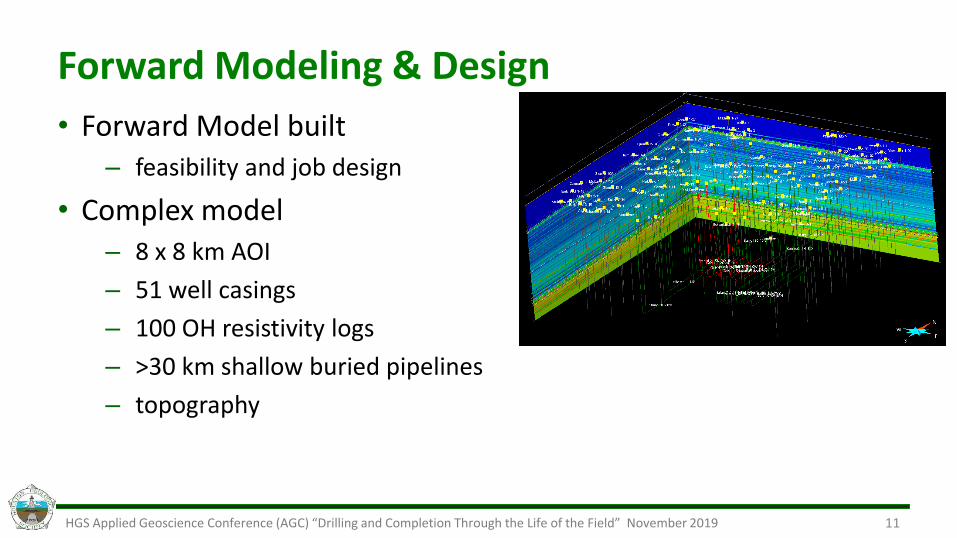
Forward Modeling & Design
• Forward Model built – feasibility and job design
• Complex model– 8 x 8 km AOI
– 51 well casings
– 100 OH resistivity logs
– >30 km shallow buried pipelines
– topography
11

HGS Applied Geoscience Conference (AGC) “Drilling and Completion Through the Life of the Field” November 2019
Geophysical Array
12

HGS Applied Geoscience Conference (AGC) “Drilling and Completion Through the Life of the Field” November 2019
Design Overview
• Well 2H: 100% EC proppant (<60 BPM)
• Well 3H: Mixture – 70% ECP / 30% Sand (70 BPM)
Parent
• Single “stage” (heel)
• Two clusters (20’)
• 160,000 lbs 40/70
• High Vis Fric Red (HVFR)
13

HGS Applied Geoscience Conference (AGC) “Drilling and Completion Through the Life of the Field” November 2019
Modeling & Calibration (baseline inversion)
14
Model Difference
Earth Model from logs, seismic and topography
Earth Model after pre frac inversion (colorscale adjusted to highlight change)
• Earth model built from apriori information• After prefrac transmit, earth model is “history matched” until the
predicted e-field response matches the actual measured e-field response.

HGS Applied Geoscience Conference (AGC) “Drilling and Completion Through the Life of the Field” November 2019
Parametric Inversion (Post Frac)
15
• Interactions between geology, casing and proppant are extremely complicated
• Parametric Inversions employed to solve for first order parameters (such as Xf, Xh, etc)
• Ellipsoid is a first order approximation for shape of propped fracture• Frac height, length and width may vary• Not necessary to be centered on the wellbore.
• Higher confidence results (estimates of fracture length, height, and average proppant concentration) at the expense of reduced detail

HGS Applied Geoscience Conference (AGC) “Drilling and Completion Through the Life of the Field” November 2019
Post Frac Inversion Highlights
• Parametric Inversion
• Final 5% misfit (fit 95% of data)
• Large drop when allowed to move
vertically/horizontally
16

HGS Applied Geoscience Conference (AGC) “Drilling and Completion Through the Life of the Field” November 2019
Well 2H
• 100% ECP
• Lower rate
• High WHTP
• Closest to
parent
17

HGS Applied Geoscience Conference (AGC) “Drilling and Completion Through the Life of the Field” November 2019
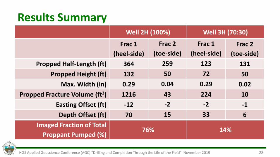
Well 2H (100%) Well 3H (70:30)
Frac 1
(heel-side)
Frac 2
(toe-side)
Frac 1
(heel-side)
Frac 2
(toe-side)
Propped Half-Length (ft) 364 259 123 131
Propped Height (ft) 132 50 72 50
Max. Width (in) 0.29 0.04 0.29 0.02
Propped Fracture Volume (ft3) 1216 43 224 10
Easting Offset (ft) -12 -2 -2 -1
Depth Offset (ft) 70 15 33 6
Imaged Fraction of Total
Proppant Pumped (%)76% 14%
Results Summary
18

HGS Applied Geoscience Conference (AGC) “Drilling and Completion Through the Life of the Field” November 2019
Frac Gradient by Stage
• Detectible stages are last stage (right)
• Frac gradient leveled out after increasing early on
• Suggests that the rock had been repressured by his time, or stress shadowing took over
• Explains lower bias towards parent by this time.

HGS Applied Geoscience Conference (AGC) “Drilling and Completion Through the Life of the Field” November 2019
Impact on Landing Zone
• Appeared to place proppant “out of zone”
• Proppant settling, lower rate
• Does this impact where to land the well in wells drilled in lower zone?

HGS Applied Geoscience Conference (AGC) “Drilling and Completion Through the Life of the Field” November 2019
Offset Pressure Analysis
• Four monitor wells
• Three interactions
• Varying VFRs
• Hydraulic geometry– Xf > 1,400’
• Hyd Xf ~4x Prop Xf
21

HGS Applied Geoscience Conference (AGC) “Drilling and Completion Through the Life of the Field” November 2019
Pressure Communication
• Well 2H: 100% EC proppant (<60 BPM)
• Well 3H: Mixture – 70% ECP / 30% Sand (70 BPM)
Parent
22
Gun Barrel View

HGS Applied Geoscience Conference (AGC) “Drilling and Completion Through the Life of the Field” November 2019
Propped Fracture Geometry Validation
• Geologic and petrophysical data based on a vertical data well.
• Multi-phase, multi-layer simulation.
• History match was achieved based on fracture dimensions identified by EM imaging.
23

HGS Applied Geoscience Conference (AGC) “Drilling and Completion Through the Life of the Field” November 2019
Summary
• Proppant biased below wellbore and towards heel perf clusters
• Depletion had little impact on geometry
– Potential recharging/stress shadowing during previous fracs
• Propped geometries (height/length) << hyd length
– Production History match supported dimensions
– Potential propped fracture “out of zone”
• Mixing of proppant (ECP/Sand) reduced signal (as expected)
24

HGS Applied Geoscience Conference (AGC) “Drilling and Completion Through the Life of the Field” November 2019
QUESTIONS?

HGS Applied Geoscience Conference (AGC) “Drilling and Completion Through the Life of the Field” November 2019
Multi-Component Receiver (each station)
26

HGS Applied Geoscience Conference (AGC) “Drilling and Completion Through the Life of the Field” November 2019
EM Components
27
HGS Applied Geoscience Conference (AGC) “Drilling and Completion Through the Life of the Field” November 2019
Well 2H (100%) Well 3H (70:30)
Frac 1
(heel-side)
Frac 2
(toe-side)
Frac 1
(heel-side)
Frac 2
(toe-side)
Propped Half-Length (ft) 364 259 123 131
Propped Height (ft) 132 50 72 50
Max. Width (in) 0.29 0.04 0.29 0.02
Propped Fracture Volume (ft3) 1216 43 224 10
Easting Offset (ft) -12 -2 -2 -1
Depth Offset (ft) 70 15 33 6
Imaged Fraction of Total
Proppant Pumped (%)76% 14%
Results Summary
28

HGS Applied Geoscience Conference (AGC) “Drilling and Completion Through the Life of the Field” November 2019
Cumulative Probability
29URTeC 2019-1035: Far-Field Proppant Imaging
Inverted FracGeometry
1 SD (+/- xx ft)
1 SD (+/- xx ft)
Uncertainty in location of frac center
1 SD (+/- xx ft)
1 SD (+/- x ft)
0 10.5
Cumulative Probability
• Hot colors indicate high likelihood that frac geometry is bigger.• Cold colors indicate high likelihood that frac geometry is smaller.

HGS Applied Geoscience Conference (AGC) “Drilling and Completion Through the Life of the Field” November 2019
Probability Example
30