et 200eco distributed i/o station - fail-safe i/o module · pdf fileet 200eco distributed i/o...
TRANSCRIPT
ET 200eco Distributed I/O Station - Fail-
Safe I/O Module
___________________
___________________
___________________
___________________
___________________
___________________
___________________
___________________
___________________
SIMATIC
ET 200eco Distributed I/O Station - Fail-Safe I/O Module
Operating Instructions
7/2013 A5E00297494-03
Preface
Product Overview 1
Configuration and Parameter Assignment
2
Address Assignment and Installation
3
Wiring 4
Diagnostics 5
General technical specifications
6
Digital F I/O Module 7
Accessories and Order Numbers
A
Response Times B

Siemens AG Industry Sector Postfach 48 48 90026 NÜRNBERG GERMANY
A5E00297494-03 10/2013 Technical data subject to change
Copyright © Siemens AG 2004 - 2013. All rights reserved
Legal information Warning notice system
This manual contains notices you have to observe in order to ensure your personal safety, as well as to prevent damage to property. The notices referring to your personal safety are highlighted in the manual by a safety alert symbol, notices referring only to property damage have no safety alert symbol. These notices shown below are graded according to the degree of danger.
DANGER indicates that death or severe personal injury will result if proper precautions are not taken.
WARNING indicates that death or severe personal injury may result if proper precautions are not taken.
CAUTION indicates that minor personal injury can result if proper precautions are not taken.
NOTICE indicates that property damage can result if proper precautions are not taken.
If more than one degree of danger is present, the warning notice representing the highest degree of danger will be used. A notice warning of injury to persons with a safety alert symbol may also include a warning relating to property damage.
Qualified Personnel The product/system described in this documentation may be operated only by personnel qualified for the specific task in accordance with the relevant documentation, in particular its warning notices and safety instructions. Qualified personnel are those who, based on their training and experience, are capable of identifying risks and avoiding potential hazards when working with these products/systems.
Proper use of Siemens products Note the following:
WARNING Siemens products may only be used for the applications described in the catalog and in the relevant technical documentation. If products and components from other manufacturers are used, these must be recommended or approved by Siemens. Proper transport, storage, installation, assembly, commissioning, operation and maintenance are required to ensure that the products operate safely and without any problems. The permissible ambient conditions must be complied with. The information in the relevant documentation must be observed.
Trademarks All names identified by ® are registered trademarks of Siemens AG. The remaining trademarks in this publication may be trademarks whose use by third parties for their own purposes could violate the rights of the owner.
Disclaimer of Liability We have reviewed the contents of this publication to ensure consistency with the hardware and software described. Since variance cannot be precluded entirely, we cannot guarantee full consistency. However, the information in this publication is reviewed regularly and any necessary corrections are included in subsequent editions.
ET 200eco Distributed I/O Station - Fail-Safe I/O Module Operating Instructions, 7/2013, A5E00297494-03 3
Preface
Purpose of this manual The information in this manual is a reference source for operations, function descriptions, and technical specifications of the ET 200eco fail-safe I/O module.
Basic knowledge requirements This manual is a supplement to the ET 200eco Distributed I/O Device manual. Working with this manual requires general knowledge of automation engineering. You also require experience of using the STEP 7 basic software and the ET 200eco distributed I/O device.
Scope of this manual Module Order number Release number and
higher Digital I/O module 4/8 F-DI DC24V PROFIsafe
6ES7 148-3FA00-0XB0 01
Approvals You will find the approvals in the chapter on standards and approvals.
The fail-safe ET 200eco I/O module also certified for use in safety mode up to:
Safety Integrity Level SIL3 according to IEC 61508:2000
Performance level (PL) e and category 4 according to ISO 13849-1:2006 or EN ISO 13849-1:2008
CE approval You will find the CE approval in the chapter on standards and approvals.
Certification Mark for Australia (C-Tick Mark) You will find the mark for Australia in the chapter on standards and approvals.
Standards You will find the standards in the chapter on standards and approvals.
Preface
ET 200eco Distributed I/O Station - Fail-Safe I/O Module 4 Operating Instructions, 7/2013, A5E00297494-03
Position in the information landscape When working with the ET 200eco fail-safe I/O module, you will need to consult the supplementary documentation listed below depending on your particular application.
References to additional documentation are included in this manual where appropriate.
Documentation Brief description of relevant contents ET 200eco Distributed I/O Device manual
• Describes all general aspects of the ET 200eco hardware (including assembly, installation and wiring of the ET 200eco)
Safety Engineering in SIMATIC S7 system description
• Provides an overview of the use, configuration, and principle of operation of S7 Distributed Safety and S7 F/FH fail-safe automation systems
• Contains a summary of detailed technical information concerning fail-safe engineering in S7-300 and S7-400
• Includes monitoring and response time calculations for S7 Distributed Safety and S7 F/FH fail-safe systems
For integration in the S7 F/FH fail-safe system
• The S7 F/FH Automation Systems manual describes the tasks that must be performed to create and commission an S7 F/FH fail-safe system.
• The S7-400, M7-400 Programmable Controllers Hardware and Installation manual describes the installation and assembly of S7-400 systems.
• The S7-400H Programmable Controllers, Fault-Tolerant Systems manual describes the CPU 41x-H central modules and the tasks required to set up and commission an S7-400H fault-tolerant system.
• The CFC for SIMATIC S7 manual/online help provides a description of programming with CFC.
Preface
ET 200eco Distributed I/O Station - Fail-Safe I/O Module Operating Instructions, 7/2013, A5E00297494-03 5
Documentation Brief description of relevant contents For integration in the S7 Distributed Safety fail-safe system
The following elements are described in the S7 Distributed Safety, Configuring and Programming manual and online help: • Configuration of the F-CPU and the F-I/O • Programming of the fail-safe CPU in fail-safe FBD or LAD. Depending on which F-CPU you are using, you will need the following documentation: • The CPU data reference manual: CPU 31xC and CPU 31x describes
the standard functions of the CPU 315F-2 DP and the CPU 317F-2 DP.
• The product information for CPU 315F-2 DP describes only the deviations from the standard CPU 315-2 DP.
• The product information for CPU 317F-2 DP describes only the deviations from the standard CPU 317-2 DP.
• The S7-400, CPU Data reference manual describes the standard functions of the CPU 416F-2.
• The product information for CPU 416F-2 describes only the deviations from the standard CPU 416-2.
• The ET 200S, Interface Module IM 151-7 CPU manual describes the standard IM 151-7 CPU.
• The product information for the IM 151-7 F-CPU describes only the deviations from the standard IM 151-7 CPU.
• The S7-300/M7-300, Module Data manual describes how to install and wire S7-300 systems.
• The CPU 31xC and CPU 31x, Technical Specifications manual describes the standard functions of the CPU 315F-2 DP.
STEP 7 manuals • The Configuring Hardware and Communication Connections with STEP 7 V5.x manual describes the operation of the standard tools of STEP 7.
• The System and Standard Functions reference manual describes functions for distributed I/O access and diagnostics.
STEP 7 online help • Describes how to operate the standard tools in STEP 7 • Contains information about how to configure and assign parameters
to modules and intelligent slaves with HW Config • Contains a description of the FBD and LAD programming languages
PCS 7 manuals • Describe the handling of the PCS 7 control system (required when the fail-safe ET 200eco I/O is integrated in a higher-level control system)
The complete collection of SIMATIC S7 documentation is available on CD-ROM.
Preface
ET 200eco Distributed I/O Station - Fail-Safe I/O Module 6 Operating Instructions, 7/2013, A5E00297494-03
Guide This manual describes the fail-safe 4/8 F-DI I/O module of the ET 200eco distributed I/O device. It consists of instructive sections and reference sections (technical specifications and appendices).
This manual covers the following basic aspects of the fail-safe I/O module:
Design and use
Configuration and parameter assignment
Addressing, assembly, and wiring
Diagnostic assessment
Technical specifications
Order numbers
Conventions In this manual, the terms "safety engineering" and "fail-safe engineering" are used synonymously. The same applies to the terms "fail-safe" and "F-" and to the terms "fail-safe I/O module" and "ET 200eco 4/8 F-DI".
"S7 Distributed Safety" and "S7 F Systems" in italics refer to the optional packages for the two F-systems: "S7 Distributed Safety" and "S7 F/FH Systems".
Recycling and disposal Due to the low levels of pollutants it contains, the fail-safe ET 200eco I/O module can be recycled. For proper recycling and disposal of your old module (device), consult a certified disposal facility for electronic scrap.
Additional support If you have any additional questions about the use of products presented in this manual, contact your local Siemens representative:
http://www.siemens.com/automation/partner
Preface
ET 200eco Distributed I/O Station - Fail-Safe I/O Module Operating Instructions, 7/2013, A5E00297494-03 7
Training Center We offer courses to help you get started with the S7 automation system. Contact your regional training center or the central training center in 90327 Nuremberg, Federal Republic of Germany.
Phone: +49 (911) 895–3200
Internet: http://www.sitrain.com
H/F Competence Center:
The H/F Competence Center in Nuremberg offers special workshops on SIMATIC S7 fail-safe and fault-tolerant (high-availability) automation systems. The H/F Competence Center can also provide assistance with onsite configuration, commissioning, and troubleshooting.
Phone: +49 (911) 895-4759 Fax: +49 (911) 895-5193
For questions about workshops, etc., contact: [email protected]
Preface
ET 200eco Distributed I/O Station - Fail-Safe I/O Module 8 Operating Instructions, 7/2013, A5E00297494-03
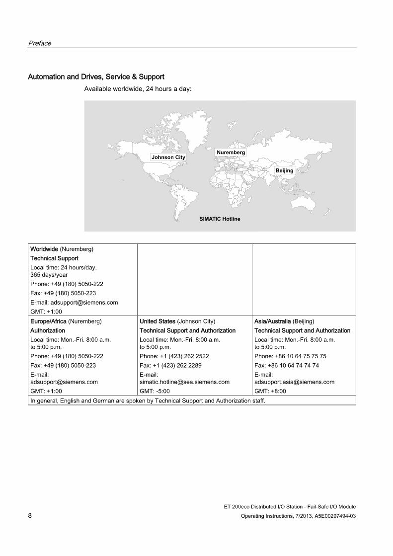
Automation and Drives, Service & Support Available worldwide, 24 hours a day:
Johnson CityNuremberg
Beijing
SIMATIC Hotline
Worldwide (Nuremberg) Technical Support Local time: 24 hours/day, 365 days/year Phone: +49 (180) 5050-222 Fax: +49 (180) 5050-223 E-mail: [email protected] GMT: +1:00
Europe/Africa (Nuremberg) Authorization Local time: Mon.-Fri. 8:00 a.m. to 5:00 p.m. Phone: +49 (180) 5050-222 Fax: +49 (180) 5050-223 E-mail: [email protected] GMT: +1:00
United States (Johnson City) Technical Support and Authorization Local time: Mon.-Fri. 8:00 a.m. to 5:00 p.m. Phone: +1 (423) 262 2522 Fax: +1 (423) 262 2289 E-mail: [email protected] GMT: -5:00
Asia/Australia (Beijing) Technical Support and Authorization Local time: Mon.-Fri. 8:00 a.m. to 5:00 p.m. Phone: +86 10 64 75 75 75 Fax: +86 10 64 74 74 74 E-mail: [email protected] GMT: +8:00
In general, English and German are spoken by Technical Support and Authorization staff.

Preface
ET 200eco Distributed I/O Station - Fail-Safe I/O Module Operating Instructions, 7/2013, A5E00297494-03 9
Service & Support on the Internet In addition to our documentation, we offer our complete knowledge base on the Internet at:
http://www.siemens.com/automation/service&support
There, you will find the following information:
Newsletters providing the latest information on your products
The right documentation for you.
Worldwide forum in which users and experts exchange ideas
Our contacts database where you can find your local Automation & Drives representative
Information on local service, repairs, and replacement parts and much more can be found under "Services."
See also Standards and Approvals (Page 37)
Preface
ET 200eco Distributed I/O Station - Fail-Safe I/O Module 10 Operating Instructions, 7/2013, A5E00297494-03
ET 200eco Distributed I/O Station - Fail-Safe I/O Module Operating Instructions, 7/2013, A5E00297494-03 11
Table of contents
Preface ...................................................................................................................................................... 3
1 Product Overview .................................................................................................................................... 13
1.1 Maintaining Operational Safety .................................................................................................... 13
1.2 Using the Fail-Safe ET 200eco I/O Module ................................................................................. 14
1.3 Components of the Fail-Safe ET 200eco ..................................................................................... 16
1.4 Guide to Commissioning the Fail-Safe ET 200eco I/O Module on PROFIBUS DP .................... 18
2 Configuration and Parameter Assignment ............................................................................................... 19
3 Address Assignment and Installation ....................................................................................................... 21
3.1 Address assignment in the F-CPU............................................................................................... 21
3.2 Assignment of the PROFIsafe address ....................................................................................... 22
3.3 Installing ....................................................................................................................................... 23
4 Wiring ...................................................................................................................................................... 25
4.1 Introduction .................................................................................................................................. 25
4.2 Safe Functional Extra-Low Voltage for the Fail-Safe I/O Module ................................................ 25
4.3 Wiring the Fail-Safe I/O Module ................................................................................................... 27
4.4 Replacing the Fail-Safe I/O Module ............................................................................................. 27
4.5 Sensor Requirements .................................................................................................................. 28
5 Diagnostics .............................................................................................................................................. 31
5.1 Reactions to Faults ...................................................................................................................... 31
5.2 Fault Diagnostics ......................................................................................................................... 32
6 General technical specifications .............................................................................................................. 37
6.1 Standards and Approvals ............................................................................................................. 37
6.2 Electromagnetic Compatibility ...................................................................................................... 41
6.3 Transport and storage conditions ................................................................................................ 45
6.4 Mechanical and Climatic Environmental Conditions .................................................................... 46
6.5 Specifications for Nominal Line Voltages, Isolation Tests, Protection Class, and Type of Protection ..................................................................................................................................... 47
7 Digital F I/O Module ................................................................................................................................. 49
7.1 Fail-Safe ET 200eco I/O Module 4/8 F-DI DC 24V PROFIsafe ................................................... 49
7.2 Use Cases of the ET 200eco 4/8 F-DI ......................................................................................... 56
7.3 Use Case 1: Safety mode SIL2/Category 3 ................................................................................. 58
Table of contents
ET 200eco Distributed I/O Station - Fail-Safe I/O Module 12 Operating Instructions, 7/2013, A5E00297494-03
7.4 Use Case 2: Safety mode SIL3/Category 3 ................................................................................ 60
7.5 Use case 3: Safety mode SIL3/Category 4 ................................................................................. 71
7.6 Diagnostic Functions of the ET 200eco 4/8 F-DI ........................................................................ 76
7.7 Technical Specifications of the ET 200eco 4/8 F-DI ................................................................... 79
A Accessories and Order Numbers ............................................................................................................. 83
B Response Times ...................................................................................................................................... 85
Glossary .................................................................................................................................................. 87
Index ........................................................................................................................................................ 89
ET 200eco Distributed I/O Station - Fail-Safe I/O Module Operating Instructions, 7/2013, A5E00297494-03 13
Product Overview 1 1.1 Maintaining Operational Safety
Important Note for Maintaining Operational Safety of Your System
Note
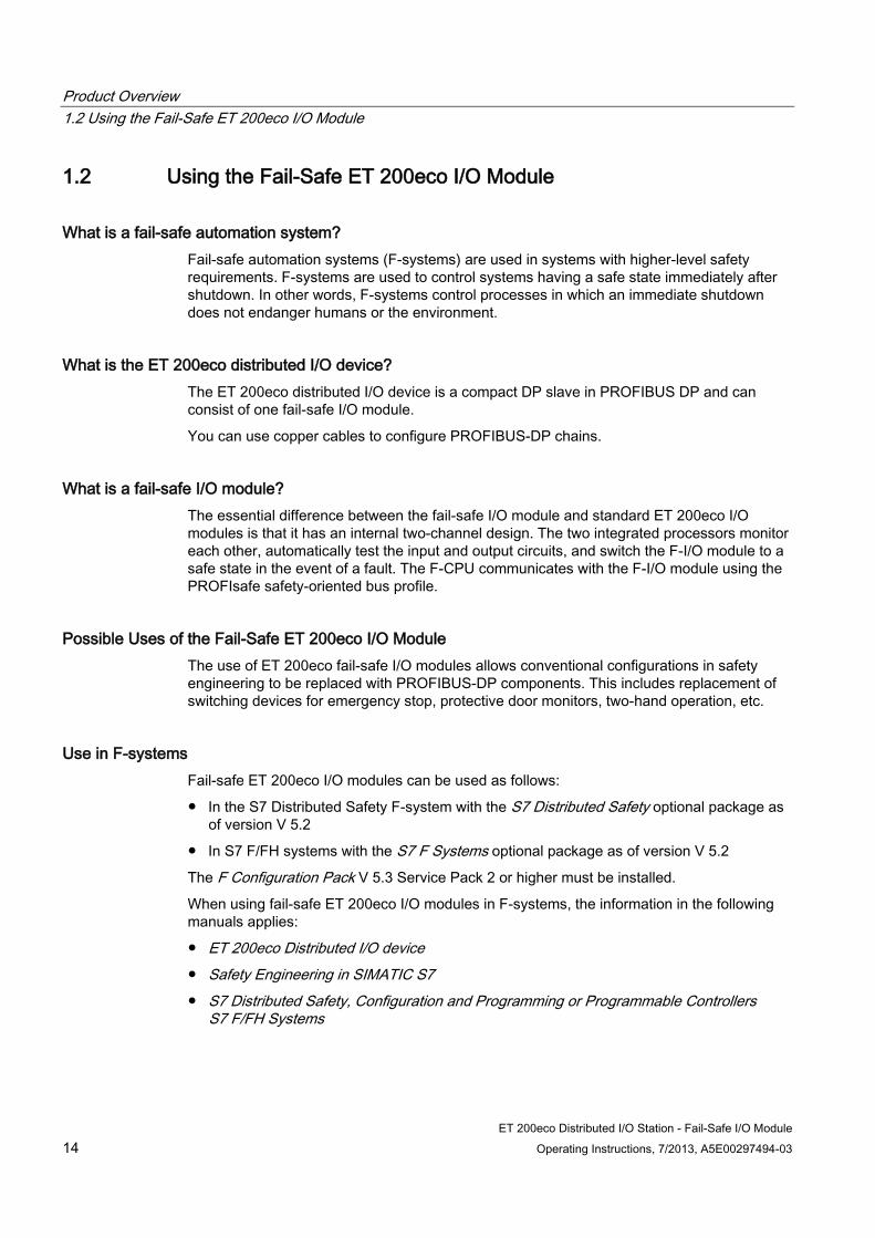
The operators of systems with safety-related characteristics must adhere to operational safety requirements. The supplier is also obliged to comply with special product monitoring measures. To keep you informed, a special newsletter is therefore available containing information on product developments and properties that are important (or potentially important) for operating systems where safety is an issue.
By subscribing to the appropriate newsletter, you will ensure that you are always up-to-date and able to make changes to your system, when necessary. Please connect to the following Internet address http://my.ad.siemens.de/myAnD/guiThemes2Select.asp?subjectID=2&lang=en and register for the following Newsletter:
– SIMATIC S7-300
– SIMATIC S7-400
– Distributed I/O
– SIMATIC Industrial Software
To receive these newsletters, select the "Updates" check box.
Product Overview 1.2 Using the Fail-Safe ET 200eco I/O Module
ET 200eco Distributed I/O Station - Fail-Safe I/O Module 14 Operating Instructions, 7/2013, A5E00297494-03
1.2 Using the Fail-Safe ET 200eco I/O Module
What is a fail-safe automation system? Fail-safe automation systems (F-systems) are used in systems with higher-level safety requirements. F-systems are used to control systems having a safe state immediately after shutdown. In other words, F-systems control processes in which an immediate shutdown does not endanger humans or the environment.
What is the ET 200eco distributed I/O device? The ET 200eco distributed I/O device is a compact DP slave in PROFIBUS DP and can consist of one fail-safe I/O module.
You can use copper cables to configure PROFIBUS-DP chains.
What is a fail-safe I/O module? The essential difference between the fail-safe I/O module and standard ET 200eco I/O modules is that it has an internal two-channel design. The two integrated processors monitor each other, automatically test the input and output circuits, and switch the F-I/O module to a safe state in the event of a fault. The F-CPU communicates with the F-I/O module using the PROFIsafe safety-oriented bus profile.
Possible Uses of the Fail-Safe ET 200eco I/O Module The use of ET 200eco fail-safe I/O modules allows conventional configurations in safety engineering to be replaced with PROFIBUS-DP components. This includes replacement of switching devices for emergency stop, protective door monitors, two-hand operation, etc.
Use in F-systems Fail-safe ET 200eco I/O modules can be used as follows:
In the S7 Distributed Safety F-system with the S7 Distributed Safety optional package as of version V 5.2
In S7 F/FH systems with the S7 F Systems optional package as of version V 5.2
The F Configuration Pack V 5.3 Service Pack 2 or higher must be installed.
When using fail-safe ET 200eco I/O modules in F-systems, the information in the following manuals applies:
ET 200eco Distributed I/O device
Safety Engineering in SIMATIC S7
S7 Distributed Safety, Configuration and Programming or Programmable Controllers S7 F/FH Systems
Product Overview 1.2 Using the Fail-Safe ET 200eco I/O Module
ET 200eco Distributed I/O Station - Fail-Safe I/O Module Operating Instructions, 7/2013, A5E00297494-03 15
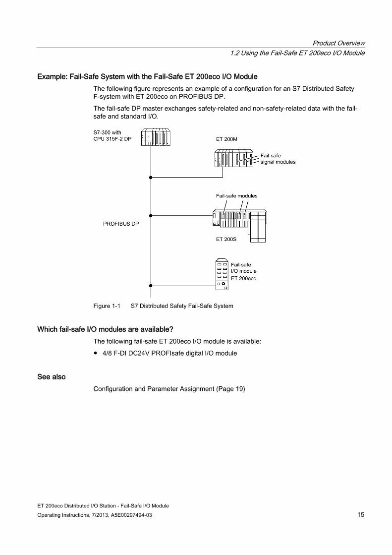
Example: Fail-Safe System with the Fail-Safe ET 200eco I/O Module The following figure represents an example of a configuration for an S7 Distributed Safety F-system with ET 200eco on PROFIBUS DP.
The fail-safe DP master exchanges safety-related and non-safety-related data with the fail-safe and standard I/O.
Figure 1-1 S7 Distributed Safety Fail-Safe System
Which fail-safe I/O modules are available? The following fail-safe ET 200eco I/O module is available:
4/8 F-DI DC24V PROFIsafe digital I/O module
See also Configuration and Parameter Assignment (Page 19)
Product Overview 1.3 Components of the Fail-Safe ET 200eco
ET 200eco Distributed I/O Station - Fail-Safe I/O Module 16 Operating Instructions, 7/2013, A5E00297494-03
1.3 Components of the Fail-Safe ET 200eco
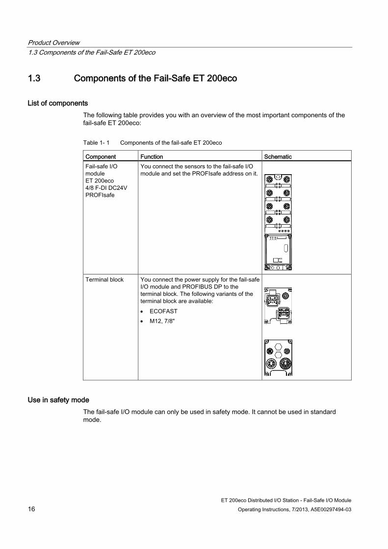
List of components The following table provides you with an overview of the most important components of the fail-safe ET 200eco:
Table 1- 1 Components of the fail-safe ET 200eco
Component Function Schematic Fail-safe I/O module ET 200eco 4/8 F-DI DC24V PROFIsafe
You connect the sensors to the fail-safe I/O module and set the PROFIsafe address on it.
Terminal block You connect the power supply for the fail-safe
I/O module and PROFIBUS DP to the terminal block. The following variants of the terminal block are available: • ECOFAST • M12, 7/8"
Use in safety mode The fail-safe I/O module can only be used in safety mode. It cannot be used in standard mode.
Product Overview 1.3 Components of the Fail-Safe ET 200eco
ET 200eco Distributed I/O Station - Fail-Safe I/O Module Operating Instructions, 7/2013, A5E00297494-03 17
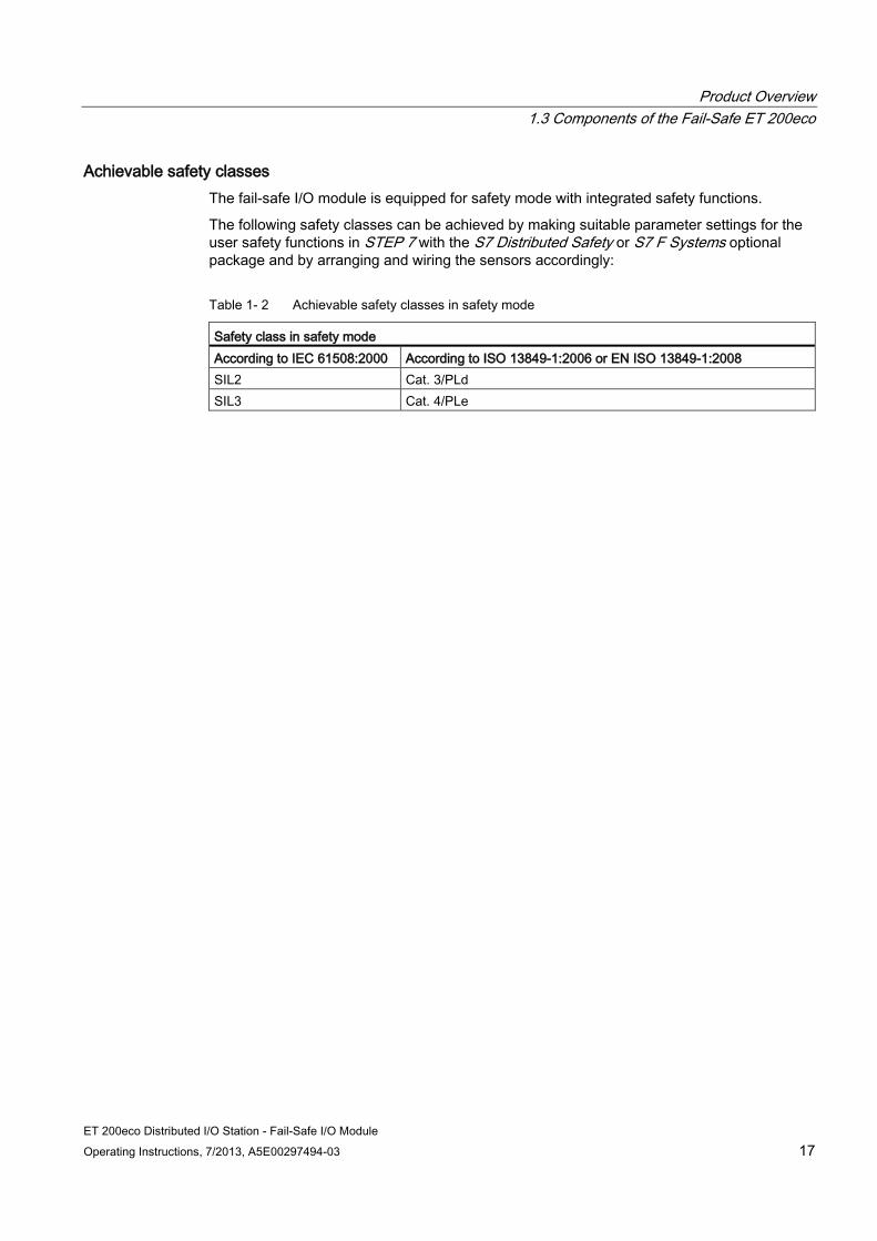
Achievable safety classes The fail-safe I/O module is equipped for safety mode with integrated safety functions.
The following safety classes can be achieved by making suitable parameter settings for the user safety functions in STEP 7 with the S7 Distributed Safety or S7 F Systems optional package and by arranging and wiring the sensors accordingly:
Table 1- 2 Achievable safety classes in safety mode
Safety class in safety mode According to IEC 61508:2000 According to ISO 13849-1:2006 or EN ISO 13849-1:2008 SIL2 Cat. 3/PLd SIL3 Cat. 4/PLe
Product Overview 1.4 Guide to Commissioning the Fail-Safe ET 200eco I/O Module on PROFIBUS DP
ET 200eco Distributed I/O Station - Fail-Safe I/O Module 18 Operating Instructions, 7/2013, A5E00297494-03
1.4 Guide to Commissioning the Fail-Safe ET 200eco I/O Module on PROFIBUS DP
Introduction The following table lists all the important steps you need to take to commission the fail-safe ET 200eco distributed I/O module as a DP slave on PROFIBUS DP.
Steps in Commissioning the Fail-Safe ET 200eco I/O Module Commissioning the fail-safe ET 200eco I/O module involves the following steps:
1. Configuring and assigning parameters to the ET 200eco 4/8 F-DI in STEP 7
2. Setting the PROFIsafe address on the ET 200eco 4/8 F-DI
3. Installing the ET 200eco 4/8 F-DI
4. Wiring the ET 200eco 4/8 F-DI
5. Commissioning the ET 200eco 4/8 F-DI on PROFIBUS DP
For more information, read the ET 200eco Distributed I/O Station manual.
6. If commissioning was not successful, run diagnostics on the ET 200eco 4/8 F-DI
For more information, refer to the ET 200eco Distributed I/O Station manual.
Note
You must configure and assign parameters to the fail-safe I/O module in STEP 7 before commissioning it.
This is required because The PROFIsafe address of the fail-safe I/O module is assigned automatically by STEP 7. You must set the switches of the failsafe I/O module to this PROFIsafe address before installing the module.
See also Configuration and Parameter Assignment (Page 19)
Installing (Page 23)
Wiring the Fail-Safe I/O Module (Page 27)
Diagnostic Functions of the ET 200eco 4/8 F-DI (Page 76)
ET 200eco Distributed I/O Station - Fail-Safe I/O Module Operating Instructions, 7/2013, A5E00297494-03 19
Configuration and Parameter Assignment 2
Requirements One of the following optional packages must be installed in STEP 7 before you can configure and assign parameters for the fail-safe I/O module.
S7 Distributed Safety, Version V5.2 Service Pack 2 or higher
S7 F Systems, Version V5.2 Service Pack 1 or higher
The following requirements also apply to the ET 200eco 4/8 F-DI:
STEP 7 V 5.2 and higher
F Configuration Pack V 5.3 Service Pack 2 and higher
You can download the F Configuration Pack from the Internet at . This ships with the optional packages S7 Distributed Safety V 5.2 Service Pack 2 or higher and S7 F Systems V 5.2 Service Pack 1 or higher.
Configuring the Fail-Safe I/O Module Follow the usual procedure with STEP 7 HW Config to configure the fail-safe I/O module (in the same way as standard ET 200eco I/O modules).
Setting I/O Module Properties To set the properties of fail-safe I/O modules:
1. Select the I/O module in STEP 7 HW Config.
2. Double-click on the "Slot 1" row of the I/O module or select the "Edit > Object Properties" menu command.
Parameters are downloaded from the programming device to the F-CPU of the DP master, where they are stored and then transferred to the fail-safe I/O module.

Configuration and Parameter Assignment
ET 200eco Distributed I/O Station - Fail-Safe I/O Module 20 Operating Instructions, 7/2013, A5E00297494-03
Setting Bus Parameters for PROFIBUS DP To comply with the values for electromagnetic compatibility, if you are using transmission rates lower than 6 Mbps, you must increase the bus parameter "Retry Limit" to at least "3" in your project engineering software (for example, COM PROFIBUS or STEP 7). Leave all other bus parameter default settings for the bus profile you are using.
Follow the steps outlined below in HW Config:
1. Open the "Network Settings" tab ("General > Properties") in the DP master system.
2. Set "User-defined" in the Profile.
3. Select Bus parameters and increase the "Retry Limit" from "1" to "3".
4. Exit the Bus Parameters dialog with "OK".
5. Open the Bus Parameters dialog again.
6. Click the Recalculate button.
7. Exit the Bus Parameters dialog with "OK".
Note
Remember that following any change to the DP master system (for example: inserting a new DP slave), you must click the Recalculate button again in the Bus Parameters dialog.
If you change to a transmission rate higher than 6 Mbps, you should set the "DP" bus profile again.
See also Address assignment in the F-CPU (Page 21)
Assignment of the PROFIsafe address (Page 22)
ET 200eco Distributed I/O Station - Fail-Safe I/O Module Operating Instructions, 7/2013, A5E00297494-03 21
Address Assignment and Installation 3 3.1 Address assignment in the F-CPU
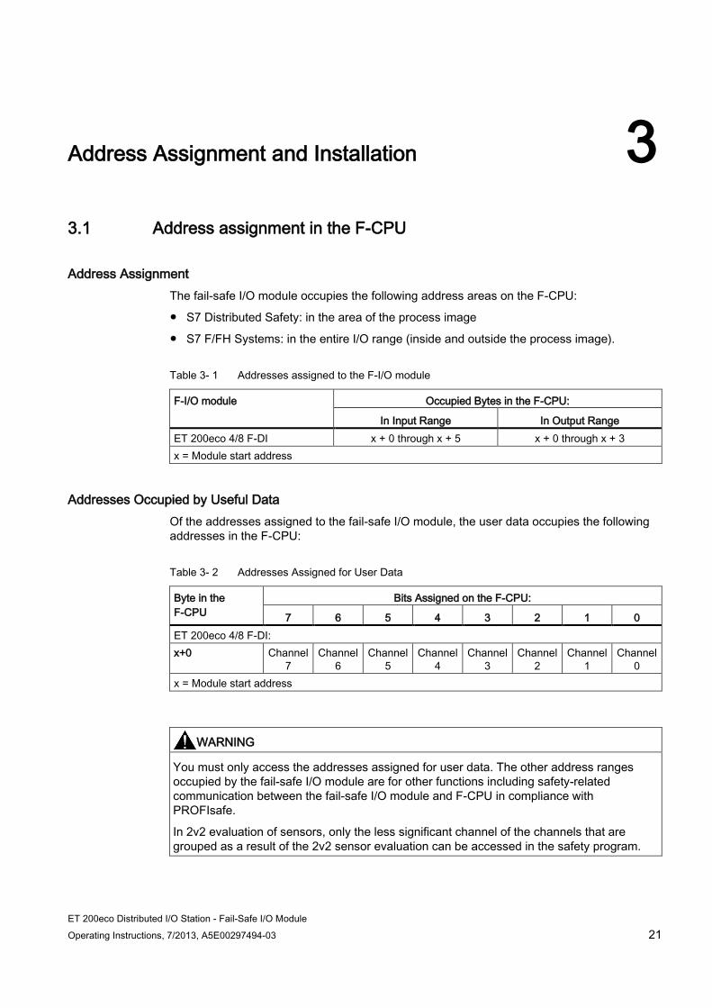
Address Assignment The fail-safe I/O module occupies the following address areas on the F-CPU:
S7 Distributed Safety: in the area of the process image
S7 F/FH Systems: in the entire I/O range (inside and outside the process image).
Table 3- 1 Addresses assigned to the F-I/O module
F-I/O module Occupied Bytes in the F-CPU:
In Input Range In Output Range ET 200eco 4/8 F-DI x + 0 through x + 5 x + 0 through x + 3 x = Module start address
Addresses Occupied by Useful Data Of the addresses assigned to the fail-safe I/O module, the user data occupies the following addresses in the F-CPU:
Table 3- 2 Addresses Assigned for User Data
Byte in the F-CPU
Bits Assigned on the F-CPU:
7 6 5 4 3 2 1 0 ET 200eco 4/8 F-DI: x+0 Channel
7 Channel
6 Channel
5 Channel
4 Channel
3 Channel
2 Channel
1 Channel
0 x = Module start address
WARNING
You must only access the addresses assigned for user data. The other address ranges occupied by the fail-safe I/O module are for other functions including safety-related communication between the fail-safe I/O module and F-CPU in compliance with PROFIsafe.
In 2v2 evaluation of sensors, only the less significant channel of the channels that are grouped as a result of the 2v2 sensor evaluation can be accessed in the safety program.
Address Assignment and Installation 3.2 Assignment of the PROFIsafe address
ET 200eco Distributed I/O Station - Fail-Safe I/O Module 22 Operating Instructions, 7/2013, A5E00297494-03
Additional Information Detailed information on F-I/O access can be found in the S7 Distributed Safety, Configuring and Programming manual or the Programmable Controllers S7 F/FH Systems manual.
3.2 Assignment of the PROFIsafe address
PROFIsafe Address Each fail-safe I/O module has its own PROFIsafe address in addition to the PROFIBUS address. Before installing the fail-safe ET 200eco I/O module, you must first set the PROFIsafe address of the fail-safe I/O module on every fail-safe I/O module.
PROFIsafe Address Assignment The PROFIsafe addresses (F_source_address, F_destination_address) are assigned automatically during configuration of the fail-safe I/O module in STEP 7. The F_destination_address is displayed in binary format in the "DIP switch setting" parameter in the object properties of the fail-safe I/O module in HW Config.
You can change the configured F_destination_address in HW Config. To prevent addressing errors, however, we recommend using the automatically assigned F_destination_address.
Address Switch for Setting PROFIsafe Addresses On the terminal block of the fail-safe I/O module, there is an address switch (10-pin DIP switch). With this address switch, you enter the PROFIsafe address (F_destination_address) of the fail-safe I/O module.
Note
Fail-safe ET 200eco I/O modules can only be used in safety mode.
Before installing the terminal block of the fail-safe I/O module, make sure that the address switch is set correctly. The PROFIsafe addresses 1 through 1022.
Address Assignment and Installation 3.3 Installing
ET 200eco Distributed I/O Station - Fail-Safe I/O Module Operating Instructions, 7/2013, A5E00297494-03 23
Rules for Address Assignment
WARNING
make sure that the address switch setting on the fail-safe I/O module matches the PROFIsafe address in STEP 7 HW Config.
The switch setting on the address switch of the F-I/O, in other words, its PROFIsafe destination address must be unique within the network* and station** (throughout the system). A maximum of 1,022 PROFIsafe destination addresses can be assigned in one system. That is, a maximum of 1,022 F-modules can be addressed using PROFIsafe.
A network consists of one or more subnets. "Network-wide" means across PROFIBUS network boundaries.
"Station-wide" means a station in HW Config (for example an S7-300 station or an I-slave)
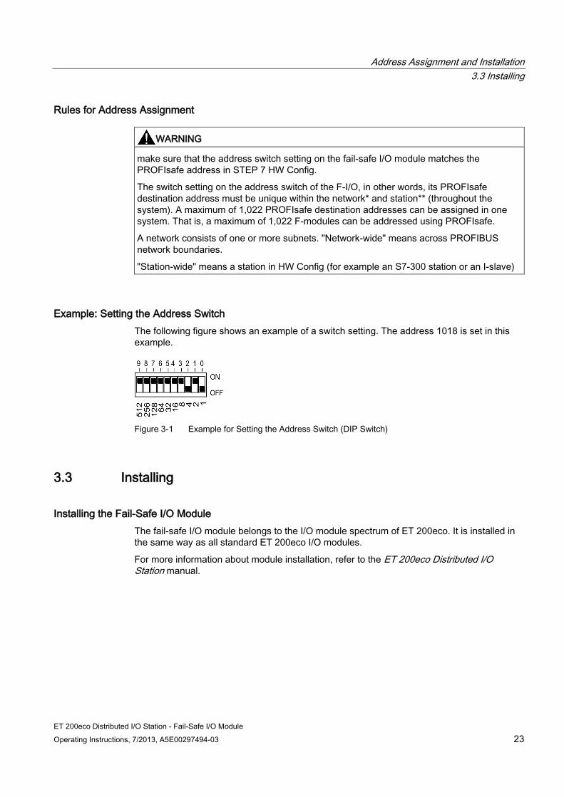
Example: Setting the Address Switch The following figure shows an example of a switch setting. The address 1018 is set in this example.
Figure 3-1 Example for Setting the Address Switch (DIP Switch)
3.3 Installing
Installing the Fail-Safe I/O Module The fail-safe I/O module belongs to the I/O module spectrum of ET 200eco. It is installed in the same way as all standard ET 200eco I/O modules.
For more information about module installation, refer to the ET 200eco Distributed I/O Station manual.
Address Assignment and Installation 3.3 Installing
ET 200eco Distributed I/O Station - Fail-Safe I/O Module 24 Operating Instructions, 7/2013, A5E00297494-03

ET 200eco Distributed I/O Station - Fail-Safe I/O Module Operating Instructions, 7/2013, A5E00297494-03 25
Wiring 4 4.1 Introduction
WARNING
In order to prevent hazardous threats to persons or the environment, you must not under any circumstances override safety functions or implement measures that cause safety functions to be bypassed or that result in the bypassing of safety functions. The manufacturer is not liable for the consequences of such manipulations or for damages that result from failure to heed this warning.
Additional Information For more detailed information on this topic that applies equally to the fail-safe I/O module and the standard ET 200eco I/O module, refer to the Distributed I/O Station ET 200eco manual.
4.2 Safe Functional Extra-Low Voltage for the Fail-Safe I/O Module
Safe functional extra low voltage
WARNING
The fail-safe I/O module must be operated with safe functional extra low voltage. This means that this module, even in the event of a fault, can only have a maximum voltage of Um applied to it. The following applies to all fail-safe I/O modules:
Um < 60.0 V
All components of the system that are capable of supplying electrical energy in any form must satisfy this requirement.
You can find additional information about safe functional extra low voltage, for example, in the data sheets of the applicable power supplies.
Each additional circuit (24 VDC) implemented must have a safe functional extra low voltage. Refer to the relevant data specification sheets or contact the manufacturer for information.
Wiring 4.2 Safe Functional Extra-Low Voltage for the Fail-Safe I/O Module
ET 200eco Distributed I/O Station - Fail-Safe I/O Module 26 Operating Instructions, 7/2013, A5E00297494-03
Note, also, that sensors having an external power supply can be connected to the fail-safe I/O module. Here, pay attention to the supply voltage from safe functional extra-low voltage. The process signal of a 24 VDC digital I/O module must not exceed a fault voltage of Um in the event of a fault.
WARNING
All power sources, for example internal 24 V DC load voltage power supplies, external 24 V DC load voltage power supplies, 5 V DC bus voltage must be electrically connected externally. This prevents voltage additions in the individual voltage sources that would cause the fault voltage Um to be exceeded even if there are voltage differences. Make sure that there is sufficient line cross section for the electrical connection, in accordance with the ET 200eco configuration guidelines (see ET 200eco Distributed I/O Station manual).
Power Supply Requirements in Compliance with NAMUR Recommendations
Note
You must use only power packs or power supplies (230 VAC --> 24 VDC) with a power failure ride-through of at least 20 ms to comply with NAMUR recommendation NE 21, IEC 61131-2, and EN 298. The following power supply board components are available, for example:
S7-400:
6ES7 407-0KA01-0AA0 for 10 A
6ES7 407-0KR00-0AA0 for 10 A
S7-300:
6ES7 307-1BA00-0AA0 for 2 A
6ES7 307-1EA00-0AA0 for 5 A
6ES7 307-1KA00-0AA0 for 10 A
These requirements also apply, of course, to power packs and power supplies that do not have an S7-300 or S7-400 configuration.
Wiring 4.3 Wiring the Fail-Safe I/O Module
ET 200eco Distributed I/O Station - Fail-Safe I/O Module Operating Instructions, 7/2013, A5E00297494-03 27
4.3 Wiring the Fail-Safe I/O Module
Same Wiring Procedure as for ET 200eco The ET 200eco fail-safe I/O module belongs to the I/O module range of ET 200eco. It is wired in the same way as all standard ET 200eco I/O modules.
For more information about wiring I/O modules, refer to the ET 200eco Distributed I/O Station manual.
WARNING
When assigning signals of the fail-safe I/O module, remember that signals should only be routed within a cable or a nonmetallic sheathed cable if:
– A short circuit in the signals does not constitute a serious safety risk
– Signals are supplied by different sensor supplies of this fail-safe I/O module
4.4 Replacing the Fail-Safe I/O Module
Replacing a Fail-Safe I/O module During Operation A fail-safe I/O module can be replaced in exactly the same way as a standard ET 200eco I/O module (turn off the power to the I/O module, remove the module, connect up the new I/O module).
Note
Note that replacing a fail-safe ET 200eco I/O module during operation causes a communication error on the F-CPU.
You must acknowledge the communication error in your safety program (for the response of the F-system after communication errors, output of a fail-safe value and user acknowledgment, refer to the manual S7 Distributed Safety, Configuration and Programming or Programmable Controllers S7 F/FH Systems).
CAUTION
Turn off the load power supply (2L+) before dismantling the terminal block. When the terminal block is dismantled, degree of protection IP 65, IP 66 or IP 67 no longer applies.
Wiring 4.5 Sensor Requirements
ET 200eco Distributed I/O Station - Fail-Safe I/O Module 28 Operating Instructions, 7/2013, A5E00297494-03
Remember to Set the PROFIsafe Address When replacing a fail-safe I/O module, make sure that the address switch (DIP switch) settings on the modules match (refer to the PROFIsafe address setting).
Note
Please refer to the information on dismantling and replacing the I/O module and the terminal block in the ET 200eco Distributed I/O Station manual.
See also Installing (Page 23)
4.5 Sensor Requirements
General requirements for sensors Note the following warning regarding safety-related use of sensors:
WARNING
The use of sensors is outside of our sphere of influence. We have equipped our electronics with such safety engineering features as to leave 85% of the maximum permissible probability of hazardous faults for sensors up to you. (This corresponds to the recommended load division in safety engineering between sensing devices, actuating devices, and electronic switching for input, processing, and output).
Note, therefore, that instrumentation with sensors involves a considerable safety responsibility. You should also bear in mind that sensors do not generally stand up to proof-test intervals of 10 years according to the IEC 61508:2000 standard without considerable loss of safety.
The probability of hazardous faults and the rate of occurrence of hazardous faults of a safety function must comply with an upper limit determined by a safety integrity level (SIL). You will find a listing of values achieved by the fail-safe I/O module under "Fail-Safe Performance Characteristics" in the technical specifications.
To achieve SIL3 (Category 4), suitably qualified sensors are necessary.
Wiring 4.5 Sensor Requirements
ET 200eco Distributed I/O Station - Fail-Safe I/O Module Operating Instructions, 7/2013, A5E00297494-03 29
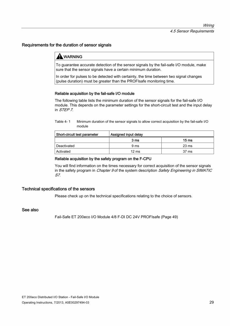
Requirements for the duration of sensor signals
WARNING
To guarantee accurate detection of the sensor signals by the fail-safe I/O module, make sure that the sensor signals have a certain minimum duration.
In order for pulses to be detected with certainty, the time between two signal changes (pulse duration) must be greater than the PROFIsafe monitoring time.
Reliable acquisition by the fail-safe I/O module
The following table lists the minimum duration of the sensor signals for the fail-safe I/O module. This depends on the parameter settings for the short-circuit test and the input delay in STEP 7.
Table 4- 1 Minimum duration of the sensor signals to allow correct acquisition by the fail-safe I/O module
Short-circuit test parameter Assigned input delay 3 ms 15 ms Deactivated 9 ms 23 ms Activated 12 ms 37 ms
Reliable acquisition by the safety program on the F-CPU
You will find information on the times necessary for correct acquisition of the sensor signals in the safety program in Chapter 9 of the system description Safety Engineering in SIMATIC S7.
Technical specifications of the sensors Please check up on the technical specifications relating to the choice of sensors.
See also Fail-Safe ET 200eco I/O Module 4/8 F-DI DC 24V PROFIsafe (Page 49)
Wiring 4.5 Sensor Requirements
ET 200eco Distributed I/O Station - Fail-Safe I/O Module 30 Operating Instructions, 7/2013, A5E00297494-03
ET 200eco Distributed I/O Station - Fail-Safe I/O Module Operating Instructions, 7/2013, A5E00297494-03 31
Diagnostics 5 5.1 Reactions to Faults
Safe State (Safety Concept) The basic principle behind the safety concept is the existence of a safe state for all process variables. For digital fail-safe I/O modules, the safe state is, for example, the value "0".
Reactions to Faults and Startup of F-System The safety function requires that the fail-safe values (safe state) are used instead of the process values for a fail-safe I/O module in the following situations (passivation of the fail-safe I/O module):
When the F-system starts up
In the case of faults during safety-related communication between the F-CPU and fail-safe I/O module using the PROFIsafe safety protocol (communication fault).
In the case of F-I/O or channel faults (for example, wire break, short circuit, discrepancy error)
WARNING
For channels that you set to "deactivated" in STEP 7, there is no diagnostic reaction or error handling if a channel error occurs, not even when such a channel is affected indirectly by a channel group error (see "Channel activated/deactivated" parameter).
Fail-safe Value Output for the Fail-Safe I/O Module For fail-safe input modules, if passivation occurs, the F-system provides fail-safe values for the safety program instead of the process values pending at the fail-safe inputs:
For fail-safe digital input modules, this is always the fail-safe value 0.
Depending on which F-system is used and the type of fault that occurred (F-I/O, channel, or communication fault), fail-safe values are used either for the affected channel only or for all channels of the fail-safe I/O module involved.
Reintegration of a Fail-Safe I/O Module Switchover from fail-safe values to process values (reintegration of a fail-safe I/O module) occurs either automatically or only after user acknowledgement in the safety program. For a fail-safe input module, the process values pending at the fail-safe inputs are provided again for the safety program after reintegration.
Diagnostics 5.2 Fault Diagnostics
ET 200eco Distributed I/O Station - Fail-Safe I/O Module 32 Operating Instructions, 7/2013, A5E00297494-03
Additional Information on Passivation and Reintegration For more detailed information on passivation and reintegration of F-I/O, refer to the S7 Distributed Safety, Configuring and Programming manual or Programmable Controllers S7 F/FH Systems manual.
See also Fail-Safe ET 200eco I/O Module 4/8 F-DI DC 24V PROFIsafe (Page 49)
5.2 Fault Diagnostics
Definition Diagnostics can be used to determine whether faults occurred during signal acquisition by the fail-safe I/O module. Diagnostic information is assigned either to one channel or to the entire fail-safe I/O module.
Diagnostic functions are not critical to safety Diagnostic functions (displays and messages) are not critical to safety and therefore are not designed to be safety-oriented functions. That is, they are not tested internally.
Diagnostic options for the fail-safe I/O module The following diagnostic options are available for the fail-safe I/O module:
LED display on front panel of the I/O module
Diagnostic functions of the fail-safe I/O module (slave diagnostics complying with the PROFIBUS standard IEC 61784-1 Ed3 CP 3/1)
Diagnostic functions that cannot be activated by the user The fail-safe I/O module provides diagnostic functions that cannot be deselected or influenced. This means that diagnostics are always activated and are automatically made available by the fail-safe I/O module in STEP 7 and passed on to the F-CPU in the event of a fault.
Diagnostic functions that can be assigned as parameters You can activate certain diagnostic functions using parameter settings in STEP 7:
The short-circuit monitoring (see short-circuit test parameter).
WARNING
Diagnostic functions should be activated or deactivated in accordance with the application.

Diagnostics 5.2 Fault Diagnostics
ET 200eco Distributed I/O Station - Fail-Safe I/O Module Operating Instructions, 7/2013, A5E00297494-03 33
Diagnostics by LED display The fail-safe I/O module indicates faults with its SF LED (group fault LED), for example
faults in the internal sensor power supplies.
– The SF-LED lights up as soon as a diagnostic function is triggered by the fail-safe I/O module.
– The SF LED flashes when a fault is cleared but has not yet been acknowledged. It goes out when all faults have been eliminated and acknowledged.
The fail-safe I/O module also has an ON LED that displays the load voltage power supply of the voltage group.
– The ON LED is lit when the sensor power supply is present.
– The ON LED flashes when there is a fault in the sensor power supply.
The fail-safe I/O module also has a BF LED to indicate bus problems.
– The BF LED is lit/flashes as soon as there is a bus problem.
– The BF LED goes off, when all bus problems have been cleared.
Slave diagnostics Slave diagnostics complies with the IEC 61784-1 Ed3 CP 3/1 standard. The fail-safe I/O module supports slave diagnostics in exactly the same way as the standard ET 200eco I/O modules.
You will find a description of the general configuration of slave diagnostics for ET 200eco and the fail-safe I/O module in the ET 200eco Distributed I/O Device manual. Below, you will find the difference relating to bytes 0, 4 and 5 as well as the channel-related diagnostics for the fail-safe I/O module.
Figure 5-1 Byte sturcture 0, 4 and 5 for slave diagnostics
Diagnostics 5.2 Fault Diagnostics
ET 200eco Distributed I/O Station - Fail-Safe I/O Module 34 Operating Instructions, 7/2013, A5E00297494-03
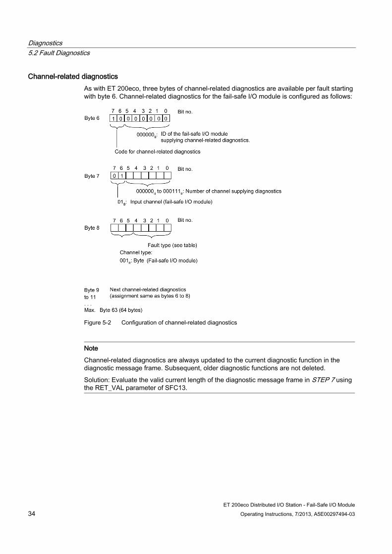
Channel-related diagnostics As with ET 200eco, three bytes of channel-related diagnostics are available per fault starting with byte 6. Channel-related diagnostics for the fail-safe I/O module is configured as follows:
Figure 5-2 Configuration of channel-related diagnostics
Note
Channel-related diagnostics are always updated to the current diagnostic function in the diagnostic message frame. Subsequent, older diagnostic functions are not deleted.
Solution: Evaluate the valid current length of the diagnostic message frame in STEP 7 using the RET_VAL parameter of SFC13.

Diagnostics 5.2 Fault Diagnostics
ET 200eco Distributed I/O Station - Fail-Safe I/O Module Operating Instructions, 7/2013, A5E00297494-03 35
Possible errors/faults of the fail-safe I/O module
Table 5- 1 Channel-related diagnostics: Fault types of the fail-safe I/O module
Fault number
Diagnostic function in STEP 7 (fault type)
Special significance for fail-safe I/O modules
1H Short circuit Short-circuit 5H Overtemperature Overtemperature 9H Fault Internal error 10H Parameter assignment error Parameter assignment error 11H Sensor voltage or load voltage is missing Missing external auxiliary supply 13H Communication error Communication error 19H Safety-related shutdown Discrepancy error
Behavior of the fail-safe I/O module in the event of module failure The following events occur following a serious internal fault in the fail-safe I/O module causing fail-safe I/O module failure:
The connection to PROFIBUS DP is interrupted and the fail-safe inputs are passivated
Diagnostic information is not sent by the fail-safe I/O module and the standard diagnostic message "module fault" is signaled.
The SF LED of the fail-safe I/O module lights up.
Specific Information about Diagnostic Functions All module-specific diagnostic functions, possible causes and remedies are described in the section on the digital fail-safe I/O module. This section also describes which status and diagnostic functions can be displayed by LEDs on the front panel of the fail-safe I/O module.
Reading diagnostic functions You can display the cause of a fault in the module diagnostics of STEP 7 (see STEP 7 Online Help).
You can read out diagnostic functions (slave diagnostics) by means of SFC 13 in the standard user program (see System and Standard Functions reference manual).
Diagnostics 5.2 Fault Diagnostics
ET 200eco Distributed I/O Station - Fail-Safe I/O Module 36 Operating Instructions, 7/2013, A5E00297494-03

ET 200eco Distributed I/O Station - Fail-Safe I/O Module Operating Instructions, 7/2013, A5E00297494-03 37
General technical specifications 6 6.1 Standards and Approvals
What are general technical specifications? The general technical specifications include standards and test values adhered to and met by the fail-safe ET 200eco I/O module and the criteria used for testing.
CE approval
The fail-safe ET 200eco I/O module satisfies the requirements and safety objectives of the following European Community directives and complies with the harmonized European standards (EN) for programmable logic controllers published in the Gazette of the European Community:
2006/42/EC "Machinery Directive"
73/23/EEC ”Electrical Equipment Designed for Use within Certain Voltage Limits” (low voltage directive)
89/336/EWG ”Electromagnetic Compatibility” (EMC Guideline)
94/9/EC " Equipment and Protective Systems Intended for Use in Potentially Explosive Atmospheres" (Explosion Protection Guideline)
The EC declarations of conformity are kept available for the relevant authorities at:
Siemens Aktiengesellschaft Bereich Automatisierungstechnik A&D AS RD ST Postfach 1963 D-92209 Amberg, Germany
UL approval
Underwriters Laboratories Inc., in accordance with
UL 508 (Industrial Control Equipment)

General technical specifications 6.1 Standards and Approvals
ET 200eco Distributed I/O Station - Fail-Safe I/O Module 38 Operating Instructions, 7/2013, A5E00297494-03
CSA Approval
Canadian Standard Association (CSA) in accordance with
C22.2 No. 142 (Process Control Equipment)
or
Underwriters Laboratories Inc., in accordance with
UL 508 (Industrial Control Equipment)
CSA C22.2 No. 142 (Process Control Equipment)
or
Underwriters Laboratories Inc., in accordance with
UL 508 (Industrial Control Equipment)
CSA C22.2 No. 142 (Process Control Equipment)
UL 1604 (Hazardous Location)
CSA-213 (Hazardous Location)
APPROVED for use in Class I, Division 2, Group A, B, C, D Tx; Class I, Zone 2, Group IIC Tx
Note
The nameplate of the specific I/O module indicates the currently valid approvals.
Marking for Australia
The fail-safe ET 200eco I/O module satisfies the AS/NZS 2064 standard (class A).
General technical specifications 6.1 Standards and Approvals
ET 200eco Distributed I/O Station - Fail-Safe I/O Module Operating Instructions, 7/2013, A5E00297494-03 39
IEC 61131 The fail-safe ET 200eco I/O module satisfies the requirements and criteria of the IEC 61131-2 standard (Programmable Controllers, Part 2: Equipment Requirements and Tests).
PROFIBUS standard The ET 200eco distributed I/O device is based on the IEC 61784-1 Ed3 CP 3/1 standard.
Shipbuilding approval Submitted to the following classification bodies:
ABS (American Bureau of Shipping)
BV (Bureau Veritas)
DNV (Det Norske Veritas)
GL (Germanischer Lloyd)
LRS (Lloyds Register of Shipping)
Class NK (Nippon Kaiji Kyokai)
Use in Industry SIMATIC products are designed for use in industrial environments.
Area of application Requirement relating to
Emitted Interference Immunity to Interference Industry EN 50081-2 : 1993 EN 50082-2 : 1995
Use in Residential Areas If you use the ET 200eco in residential areas, you must ensure limit class B (EN 55011) for emission of radio interferences.
Suitable measures for achieving limit class B for emission of radio interference are:
Installing the ET 200eco in grounded switching cubicles/switch boxes
Use of filters in power supply lines
General technical specifications 6.1 Standards and Approvals
ET 200eco Distributed I/O Station - Fail-Safe I/O Module 40 Operating Instructions, 7/2013, A5E00297494-03
TÜV Certificate and Standards The fail-safe ET 200eco I/O module is certified for the following standards. Refer to the report accompanying the TÜV certificate for the current version/edition of the standard.
Standards/Directives Functional Safety
Standards/Directives Machine Safety
Additional Standards/Guidelines
DIN V 19250 98/37/EC DIN VDE 0110-1 DIN V VDE 0801 EN 60204-1 DIN VDE 0160 DIN V VDE 0801/A1 Standards/Directives for Fuel
Engineering 93/68/EEC
IEC 61508:2000 DIN VDE 0116, Clause 8.7 92/31/EEC and 93/68/EEC prEN 50159-1 and 2 prEN 50156-1 DIN EN 55011 Standards/Directives for Process Engineering
EN 230, Clause 7.3 EN 50081-2
DIN V 19251 EN 298, Clauses 7.3, 8, 9, and 10
EN 61000-6-2
VDI/VDE 2180-1 to 5 DIN V ENV 1954 DIN EN 61131-2 NE 31 ISA S 84.01
Requesting TÜV Certificate You can request copies of the TÜV certificate and the accompanying report at the following address:
Siemens Aktiengesellschaft Bereich Automatisierungstechnik A&D AS RD ST Postfach 1963 D-92209 Amberg, Germany
General technical specifications 6.2 Electromagnetic Compatibility
ET 200eco Distributed I/O Station - Fail-Safe I/O Module Operating Instructions, 7/2013, A5E00297494-03 41
6.2 Electromagnetic Compatibility
Introduction This section contains information on the interference immunity of the fail-safe I/O module and information on radio interference suppression.
Definition of EMC Electromagnetic compatibility is the ability of an electrical device to function in its electromagnetic environment in a satisfactory manner without affecting this environment.
The fail-safe ET 200eco I/O module also satisfies the requirements of the EMC directive of the European Economic Area. This is possible only when the ET 200S distributed I/O station complies with the specifications and guidelines for electrical assembly.
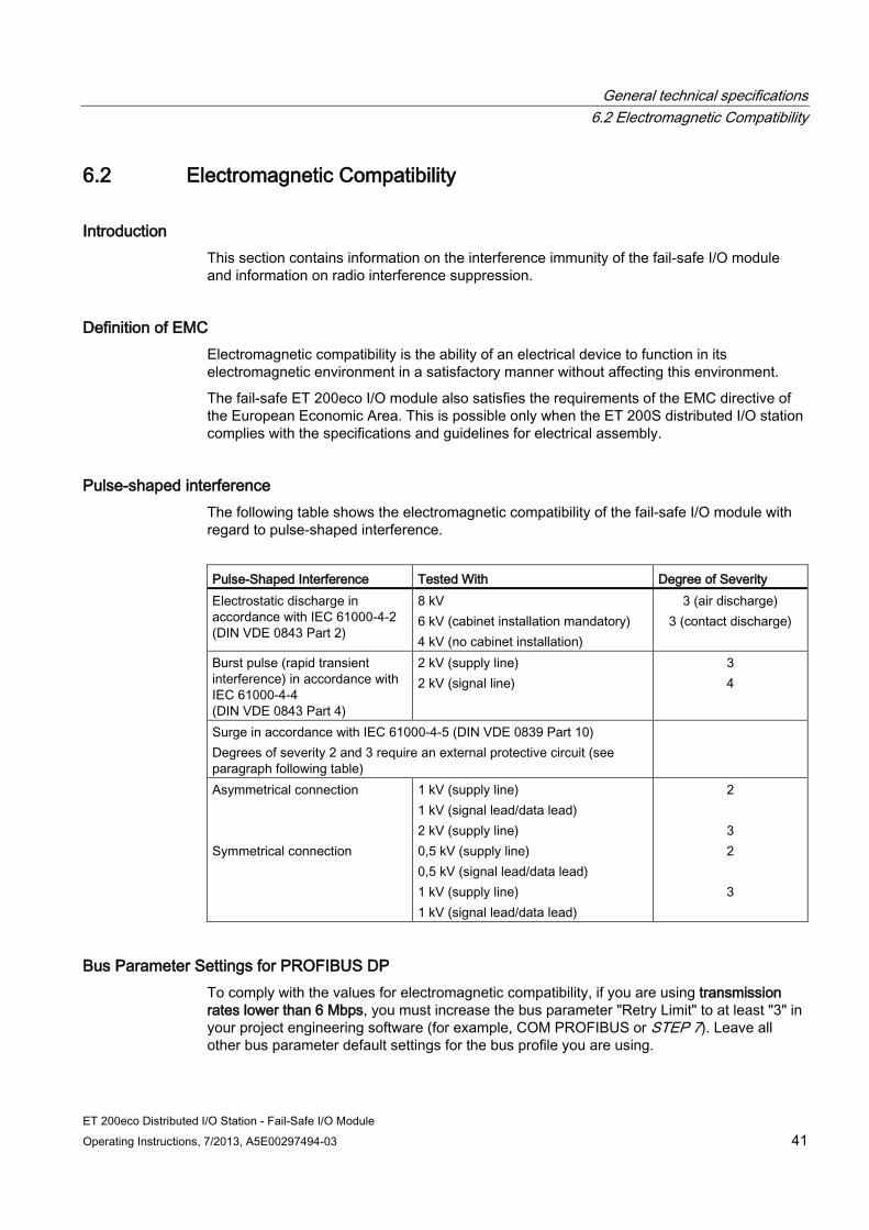
Pulse-shaped interference The following table shows the electromagnetic compatibility of the fail-safe I/O module with regard to pulse-shaped interference.
Pulse-Shaped Interference Tested With Degree of Severity Electrostatic discharge in accordance with IEC 61000-4-2 (DIN VDE 0843 Part 2)
8 kV 6 kV (cabinet installation mandatory) 4 kV (no cabinet installation)
3 (air discharge) 3 (contact discharge)
Burst pulse (rapid transient interference) in accordance with IEC 61000-4-4 (DIN VDE 0843 Part 4)
2 kV (supply line) 2 kV (signal line)
3 4
Surge in accordance with IEC 61000-4-5 (DIN VDE 0839 Part 10) Degrees of severity 2 and 3 require an external protective circuit (see paragraph following table)
Asymmetrical connection Symmetrical connection
1 kV (supply line) 1 kV (signal lead/data lead) 2 kV (supply line) 0,5 kV (supply line) 0,5 kV (signal lead/data lead) 1 kV (supply line) 1 kV (signal lead/data lead)
2
3 2
3
Bus Parameter Settings for PROFIBUS DP To comply with the values for electromagnetic compatibility, if you are using transmission rates lower than 6 Mbps, you must increase the bus parameter "Retry Limit" to at least "3" in your project engineering software (for example, COM PROFIBUS or STEP 7). Leave all other bus parameter default settings for the bus profile you are using.
General technical specifications 6.2 Electromagnetic Compatibility
ET 200eco Distributed I/O Station - Fail-Safe I/O Module 42 Operating Instructions, 7/2013, A5E00297494-03
Protecting the Fail-Safe ET 200eco I/O Module from Overvoltages If your equipment makes protection from overvoltage necessary, you must use an external protective circuit (surge filter) between the load voltage power supply and the load voltage input of the I/O module to ensure surge immunity for the fail-safe ET 200eco I/O module.
Note
Lightning protection measures always require a case-by-case examination of the entire system. Nearly complete protection from overvoltages, however, can only be achieved if the entire building surroundings have been designed for overvoltage protection. In particular, this involves structural measures in the building design phase.
Therefore, for detailed information regarding overvoltage protection, we recommend that you contact your Siemens representative or a company specializing in lightning protection.
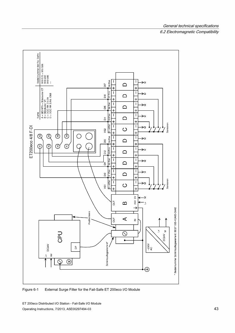
The following figure shows an example of an external surge filter for the fail-safe ET 200eco I/O module.
For additional information about surge protection for standard I/O modules, refer to the ET 200eco Distributed I/O Station manual.
General technical specifications 6.2 Electromagnetic Compatibility
ET 200eco Distributed I/O Station - Fail-Safe I/O Module Operating Instructions, 7/2013, A5E00297494-03 43
Figure 6-1 External Surge Filter for the Fail-Safe ET 200eco I/O Module
General technical specifications 6.2 Electromagnetic Compatibility
ET 200eco Distributed I/O Station - Fail-Safe I/O Module 44 Operating Instructions, 7/2013, A5E00297494-03
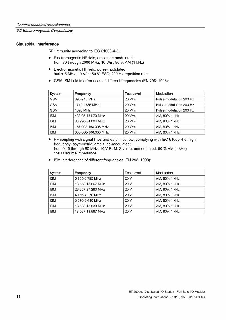
Sinusoidal interference RFI immunity according to IEC 61000-4-3:
Electromagnetic HF field, amplitude modulated: from 80 through 2000 MHz; 10 V/m; 80 % AM (1 kHz)
Electromagnetic HF field, pulse-modulated: 900 ± 5 MHz; 10 V/m; 50 % ESD; 200 Hz repetition rate
GSM/ISM field interferences of different frequencies (EN 298: 1998):
System Frequency Test Level Modulation GSM 890-915 MHz 20 V/m Pulse modulation 200 Hz GSM 1710-1785 MHz 20 V/m Pulse modulation 200 Hz GSM 1890 MHz 20 V/m Pulse modulation 200 Hz ISM 433.05-434.79 MHz 20 V/m AM, 80% 1 kHz ISM 83,996-84,004 MHz 20 V/m AM, 80% 1 kHz ISM 167.992-168.008 MHz 20 V/m AM, 80% 1 kHz ISM 886.000-906.000 MHz 20 V/m AM, 80% 1 kHz
HF coupling with signal lines and data lines, etc. complying with IEC 61000-4-6, high frequency, asymmetric, amplitude-modulated: from 0.15 through 80 MHz; 10 V R. M. S value, unmodulated; 80 % AM (1 kHz); 150 Ω source impedance
ISM interferences of different frequencies (EN 298: 1998):
System Frequency Test Level Modulation ISM 6,765-6,795 MHz 20 V AM, 80% 1 kHz ISM 13,553-13,567 MHz 20 V AM, 80% 1 kHz ISM 26,957-27,283 MHz 20 V AM, 80% 1 kHz ISM 40.66-40.70 MHz 20 V AM, 80% 1 kHz ISM 3.370-3.410 MHz 20 V AM, 80% 1 kHz ISM 13.533-13.533 MHz 20 V AM, 80% 1 kHz ISM 13.567-13.587 MHz 20 V AM, 80% 1 kHz

General technical specifications 6.3 Transport and storage conditions
ET 200eco Distributed I/O Station - Fail-Safe I/O Module Operating Instructions, 7/2013, A5E00297494-03 45
Radio Interference Emission Emitted interference of electromagnetic fields according to EN 55011: Limit value class A, group 1 (measured at a distance of 10 m).
Frequency Emitted Interference Between 30 MHz and 230 MHz < 40 dB (µV/m)Q Between 230 MHz and 1000 MHz < 47 dB (µV/m)Q
Emitted interference over network AC power supply in accordance with EN 55011: Limit class A, group 1.
Frequency Emitted Interference Between 0,15 MHz and 0,5 MHz < 79 dB (µV)Q, < 66 dB (µV)M Between 0,5 MHz and 5 MHz < 73 dB (µV)Q, < 60 dB (µV)M Between 5 MHz and 30 MHz < 73 dB (µV)Q, < 60 dB (µV)M
See also Configuration and Parameter Assignment (Page 19)
6.3 Transport and storage conditions
Conditions for the Fail-Safe I/O Module In terms of transport and storage conditions, the ET 200eco fail-safe I/O module surpasses the requirements according to IEC 61131-2.
The following information applies to fail-safe I/O modules that are transported and/or stored in their original packaging.
Type of Condition Permissible range Free fall ≤ 1 m Temperature from -40 °C through +70 °C Temperature change 20 K/h Air pressure 1080 hPa to 660 hPa
(corresponds to an altitude of -1000 m to 3500 m) Relative humidity 5% to 95%, without condensation
General technical specifications 6.4 Mechanical and Climatic Environmental Conditions
ET 200eco Distributed I/O Station - Fail-Safe I/O Module 46 Operating Instructions, 7/2013, A5E00297494-03
6.4 Mechanical and Climatic Environmental Conditions
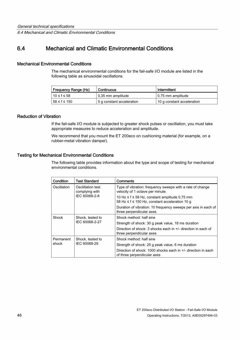
Mechanical Environmental Conditions The mechanical environmental conditions for the fail-safe I/O module are listed in the following table as sinusoidal oscillations.
Frequency Range (Hz) Continuous Intermittent 10 ≤ f ≤ 58 0,35 mm amplitude 0.75 mm amplitude 58 ≤ f ≤ 150 5 g constant acceleration 10 g constant acceleration
Reduction of Vibration If the fail-safe I/O module is subjected to greater shock pulses or oscillation, you must take appropriate measures to reduce acceleration and amplitude.
We recommend that you mount the ET 200eco on cushioning material (for example, on a rubber-metal vibration damper).
Testing for Mechanical Environmental Conditions The following table provides information about the type and scope of testing for mechanical environmental conditions.
Condition Test Standard Comments Oscillation Osclillation test
complying with IEC 60068-2-8
Type of vibration: frequency sweeps with a rate of change velocity of 1 octave per minute. 10 Hz ≤ f ≤ 58 Hz, constant amplitude 0,75 mm 58 Hz ≤ f ≤ 150 Hz, constant acceleration 10 g Duration of vibration: 10 frequency sweeps per axis in each of three perpendicular axes
Shock Shock, tested to IEC 60068-2-27
Shock method: half sine Strength of shock: 30 g peak value, 18 ms duration Direction of shock: 3 shocks each in +/- direction in each of three perpendicular axes
Permanent shock
Shock, tested to IEC 60068-29
Shock method: half sine Strength of shock: 25 g peak value, 6 ms duration Direction of shock: 1000 shocks each in +/- direction in each of three perpendicular axes
General technical specifications 6.5 Specifications for Nominal Line Voltages, Isolation Tests, Protection Class, and Type of Protection
ET 200eco Distributed I/O Station - Fail-Safe I/O Module Operating Instructions, 7/2013, A5E00297494-03 47
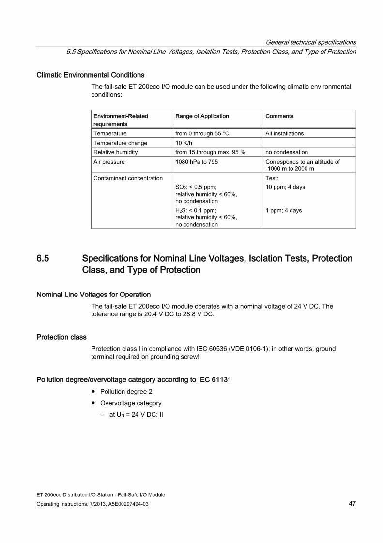
Climatic Environmental Conditions The fail-safe ET 200eco I/O module can be used under the following climatic environmental conditions:
Environment-Related requirements
Range of Application Comments
Temperature from 0 through 55 °C All installations Temperature change 10 K/h Relative humidity from 15 through max. 95 % no condensation Air pressure 1080 hPa to 795 Corresponds to an altitude of
-1000 m to 2000 m Contaminant concentration
SO2: < 0.5 ppm; relative humidity < 60%, no condensation H2S: < 0.1 ppm; relative humidity < 60%, no condensation
Test: 10 ppm; 4 days 1 ppm; 4 days
6.5 Specifications for Nominal Line Voltages, Isolation Tests, Protection Class, and Type of Protection
Nominal Line Voltages for Operation The fail-safe ET 200eco I/O module operates with a nominal voltage of 24 V DC. The tolerance range is 20.4 V DC to 28.8 V DC.
Protection class Protection class I in compliance with IEC 60536 (VDE 0106-1); in other words, ground terminal required on grounding screw!
Pollution degree/overvoltage category according to IEC 61131 Pollution degree 2
Overvoltage category
– at UN = 24 V DC: II

General technical specifications 6.5 Specifications for Nominal Line Voltages, Isolation Tests, Protection Class, and Type of Protection
ET 200eco Distributed I/O Station - Fail-Safe I/O Module 48 Operating Instructions, 7/2013, A5E00297494-03
Degree of protection IP 65 Degree of protection to IEC 529
Protection against ingress of dust and full protection against touch
Protection against a stream of water from a nozzle onto the enclosure from all directions. (The water must not have any detrimental effects.)
Degree of protection IP 66 and 67 Degree of protection to IEC 529
Protection against ingress of dust and full protection against touch
IP 66: Protection against heavy seas or strong water stream. (Water must not enter the enclosure in harmful quantities.)
IP 67: Protection against water when the enclosure is immersed in water under specified pressure and time conditions. (Water must not enter the enclosure in harmful quantities.)
ET 200eco Distributed I/O Station - Fail-Safe I/O Module Operating Instructions, 7/2013, A5E00297494-03 49
Digital F I/O Module 7 7.1 Fail-Safe ET 200eco I/O Module 4/8 F-DI DC 24V PROFIsafe
Order number 6ES7 148-3FA00-0XB0
Properties The 4/8 F-DI DC24V PROFIsafe fail-safe I/O module has the following properties:
8 inputs (SIL2/Category 3) or 4 inputs (SIL3/Category 3 or Category 4)
24 V DC nominal input voltage
Suitable for switches and 3 or 4-wire proximity switches (BEROs)
Two short-circuit-proof sensor supplies each for four inputs
External sensor supply possible
Group fault display (SF; red LED)
Status display for each input (green LED)
Bus fault display (BF; red LED)
A common fault display for both sensor power supplies (green ON LED flashes)
Configurable diagnostics
Note
The safety-related characteristics in the technical specifications apply for a proof-test interval of 10 years and a repair time of 100 hours.
Digital F I/O Module 7.1 Fail-Safe ET 200eco I/O Module 4/8 F-DI DC 24V PROFIsafe
ET 200eco Distributed I/O Station - Fail-Safe I/O Module 50 Operating Instructions, 7/2013, A5E00297494-03
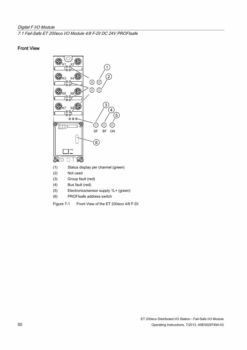
Front View
(1) Status display per channel (green) (2) Not used (3) Group fault (red) (4) Bus fault (red) (5) Electronics/sensor supply 1L+ (green) (6) PROFIsafe address switch
Figure 7-1 Front View of the ET 200eco 4/8 F-DI

Digital F I/O Module 7.1 Fail-Safe ET 200eco I/O Module 4/8 F-DI DC 24V PROFIsafe
ET 200eco Distributed I/O Station - Fail-Safe I/O Module Operating Instructions, 7/2013, A5E00297494-03 51
Terminal assignment The following table shows the assignment of the 8 female connectors of the fail-safe ET 200eco I/O module for connecting the digital inputs.
Table 7- 1 Pin Assignment of the Sockets X1 through X8 for Digital Inputs
Pin Assignment of Socket X1
Assignment of Socket X2
Assignment of Socket X3
Assignment of Socket X4
View of the Socket (from front)
1 24 V sensor supply 1
2* Input signal channel 4 Input signal channel 5 Input signal channel 6 Input signal channel 7 3 Ground sensor power supply (1M) 4 Input signal channel 0 Input signal channel 1 Input signal channel 2 Input signal channel 3 5 24 V sensor supply 2 Pin Assignment of
Socket X5 Assignment of Socket X6
Assignment of Socket X7
Assignment of Socket X8
1 24 V sensor supply 2 2 Not used 3 Ground sensor power supply (1M) 4 Input signal channel 4 Input signal channel 5 Input signal channel 6 Input signal channel 7 5 Not used * Pin 2: The contact of the second channel (X5-X8) is looped through (1oo2 evaluation 1-channel sensor, see use case 2.1 – one sensor connected over one channel to two inputs)
Digital F I/O Module 7.1 Fail-Safe ET 200eco I/O Module 4/8 F-DI DC 24V PROFIsafe
ET 200eco Distributed I/O Station - Fail-Safe I/O Module 52 Operating Instructions, 7/2013, A5E00297494-03
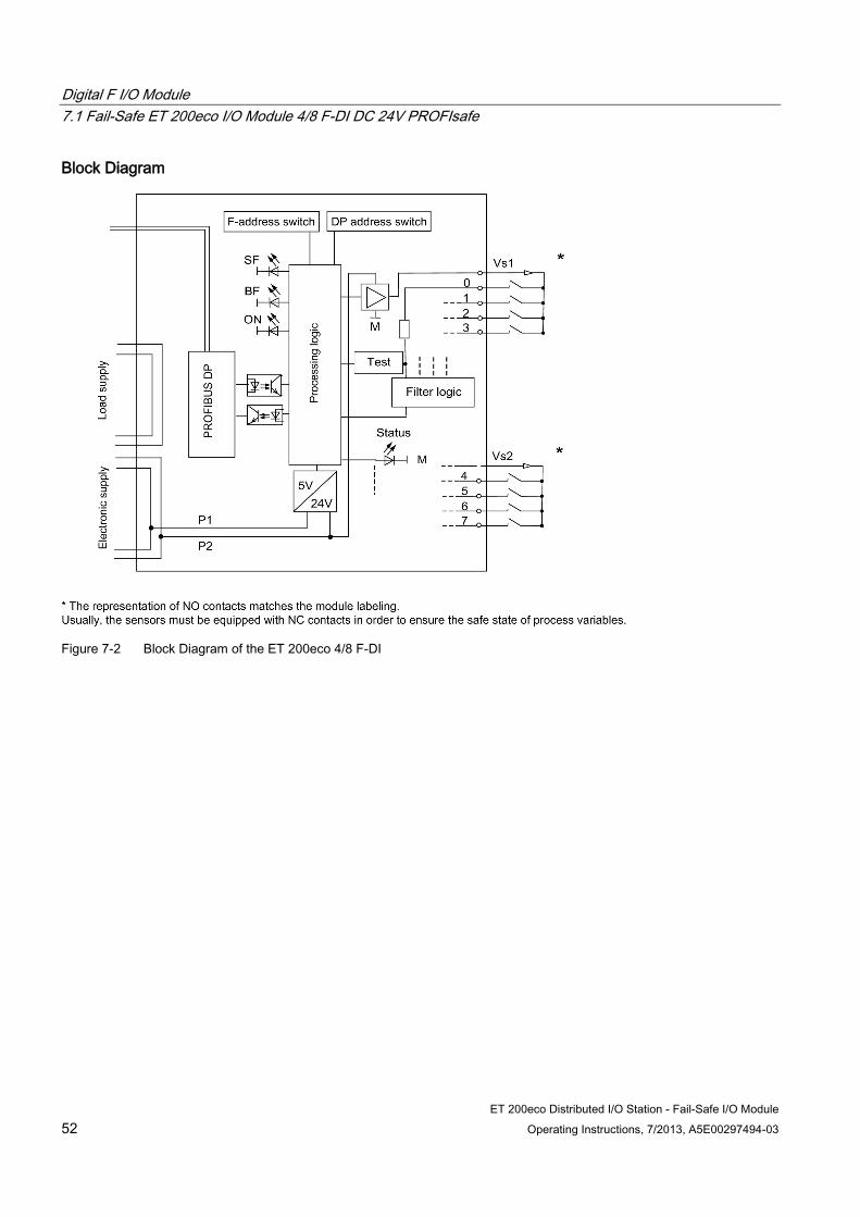
Block Diagram
Figure 7-2 Block Diagram of the ET 200eco 4/8 F-DI
Digital F I/O Module 7.1 Fail-Safe ET 200eco I/O Module 4/8 F-DI DC 24V PROFIsafe
ET 200eco Distributed I/O Station - Fail-Safe I/O Module Operating Instructions, 7/2013, A5E00297494-03 53
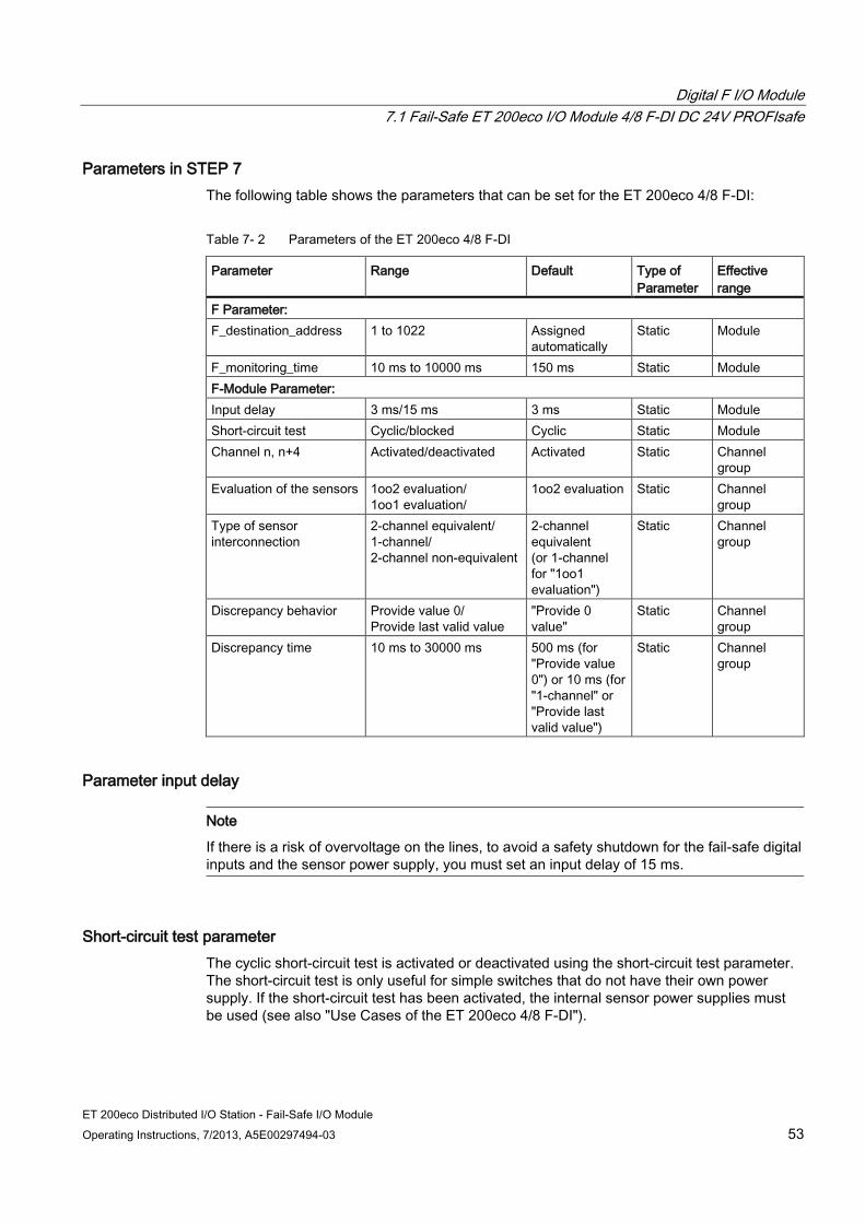
Parameters in STEP 7 The following table shows the parameters that can be set for the ET 200eco 4/8 F-DI:
Table 7- 2 Parameters of the ET 200eco 4/8 F-DI
Parameter Range Default Type of Parameter
Effective range
F Parameter: F_destination_address 1 to 1022 Assigned
automatically Static Module
F_monitoring_time 10 ms to 10000 ms 150 ms Static Module F-Module Parameter: Input delay 3 ms/15 ms 3 ms Static Module Short-circuit test Cyclic/blocked Cyclic Static Module Channel n, n+4 Activated/deactivated Activated Static Channel
group Evaluation of the sensors 1oo2 evaluation/
1oo1 evaluation/ 1oo2 evaluation Static Channel
group Type of sensor interconnection
2-channel equivalent/ 1-channel/ 2-channel non-equivalent
2-channel equivalent (or 1-channel for "1oo1 evaluation")
Static Channel group
Discrepancy behavior Provide value 0/ Provide last valid value
"Provide 0 value"
Static Channel group
Discrepancy time 10 ms to 30000 ms 500 ms (for "Provide value 0") or 10 ms (for "1-channel" or "Provide last valid value")
Static Channel group
Parameter input delay
Note
If there is a risk of overvoltage on the lines, to avoid a safety shutdown for the fail-safe digital inputs and the sensor power supply, you must set an input delay of 15 ms.
Short-circuit test parameter The cyclic short-circuit test is activated or deactivated using the short-circuit test parameter. The short-circuit test is only useful for simple switches that do not have their own power supply. If the short-circuit test has been activated, the internal sensor power supplies must be used (see also "Use Cases of the ET 200eco 4/8 F-DI").

Digital F I/O Module 7.1 Fail-Safe ET 200eco I/O Module 4/8 F-DI DC 24V PROFIsafe
ET 200eco Distributed I/O Station - Fail-Safe I/O Module 54 Operating Instructions, 7/2013, A5E00297494-03
Behavior of discrepancy parameter As the "response to discrepancy", you set the value that is made available to the safety program in the F-CPU while there is a discrepancy between the two input channels involved; in other words, during the discrepancy time. You set the response to a discrepancy as follows:
"provide last valid value" or
"Provide value 0"
Requirements You have set the following:
Evaluation of the sensors: "1oo2 evaluation" and
Type of sensor interconnection: "2-channel equivalent" or "2-channel non-equivalent"
"Provide Last Valid Value"
The last valid value (old value) before discrepancy occurs is made available in the safety program in the fail-safe CPU as soon as a discrepancy is detected between the signals of the affected input channels. This value remains available until the discrepancy disappears or until the discrepancy time expires and a discrepancy error is detected. The sensor-actuator response time is extended according to the this time.
As a result, the discrepancy time of sensors connected over two channels must be set for fast responses to short response times. It makes no sense, for example, if sensors connected over two channels with a discrepancy time of 500 ms trigger a time-critical shutdown. In the worst case, the sensor-actuator response time is extended by an amount approximately equal to the discrepancy time:
For this reason, position the sensor in the process in such a way as to minimize discrepancy.
You should then select the shortest possible discrepancy time that nevertheless also provides adequate reserves to prevent incorrect triggering of discrepancy errors.
"Provide value 0"
The value "0" is made available to the safety program in the F-CPU as soon as a discrepancy is detected between the signals of the two affected input channels.
If you assigned the parameter "Provide value 0", the sensor-actuator response time will not be affected by the discrepancy time.
Digital F I/O Module 7.1 Fail-Safe ET 200eco I/O Module 4/8 F-DI DC 24V PROFIsafe
ET 200eco Distributed I/O Station - Fail-Safe I/O Module Operating Instructions, 7/2013, A5E00297494-03 55
Discrepancy time parameter Here, you can specify the discrepancy time for each pair of channels. The value entered is rounded to whole multiples of 10 ms.
Requirements
You have set the following:
Evaluation of the sensors: "1oo2 evaluation" and
Type of sensor interconnection: "2-channel equivalent" or "2-channel non-equivalent"
Discrepancy Analysis and Discrepancy Time
If you use a 2-channel, one non-equivalent, or two 1-channel sensors, that measure the same physical process variable, the sensors will respond with a slight time delay among each other due to the limited accuracy of the arrangement.
Discrepancy analysis for equivalence or non-equivalence is used for fail-safe inputs in order to determine faults based on the time characteristic of two signals with the same functionality. The discrepancy analysis starts when different levels (when checking for non-equivalence: the same level) are detected for two related input signals. The signals are checked to establish whether the difference (when checking for non-equivalence: conformity) has disappeared after expiration of a specified time known as the discrepancy time. If not, this means that a discrepancy error exists.
The most cases, the discrepancy time is started but is not elapse fully since the signal differences disappear after a short time.
Select the discrepancy time large enough so that in case of no error the difference of the two signals (when checking for non-equivalence: signals matching) has disappeared in every case before the discrepancy time is elapsed.
Response While the Discrepancy Time Is Running
While the discrepancy time is running internally on the module, either the last valid value or "0" is provided for the safety program on the F-CPU by the input channels involved depending on the parameter settings for the response to discrepancy.
Response after the Discrepancy Time Elapses
If the input signals do not match after the specified discrepancy time has elapsed (when checking for non-equivalence: inequality), for example due to a break in the sensor wire, a discrepancy error is detected and the "discrepancy" diagnostic message is generated in the diagnostic buffer of the fail-safe I/O module indicating the faulty channels.
See also Configuration and Parameter Assignment (Page 19)
Use case 3: Safety mode SIL3/Category 4 (Page 71)
Digital F I/O Module 7.2 Use Cases of the ET 200eco 4/8 F-DI
ET 200eco Distributed I/O Station - Fail-Safe I/O Module 56 Operating Instructions, 7/2013, A5E00297494-03
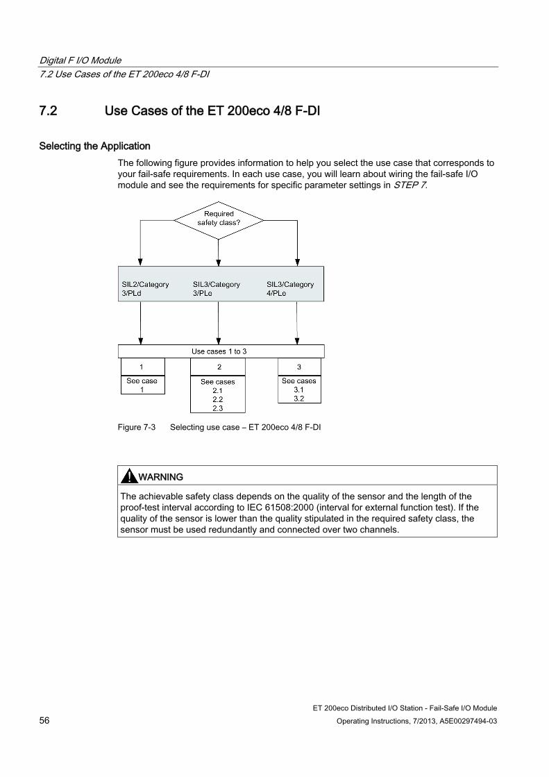
7.2 Use Cases of the ET 200eco 4/8 F-DI
Selecting the Application The following figure provides information to help you select the use case that corresponds to your fail-safe requirements. In each use case, you will learn about wiring the fail-safe I/O module and see the requirements for specific parameter settings in STEP 7.
Figure 7-3 Selecting use case – ET 200eco 4/8 F-DI
WARNING
The achievable safety class depends on the quality of the sensor and the length of the proof-test interval according to IEC 61508:2000 (interval for external function test). If the quality of the sensor is lower than the quality stipulated in the required safety class, the sensor must be used redundantly and connected over two channels.
Digital F I/O Module 7.3 Use Case 1: Safety mode SIL2/Category 3
ET 200eco Distributed I/O Station - Fail-Safe I/O Module Operating Instructions, 7/2013, A5E00297494-03 57
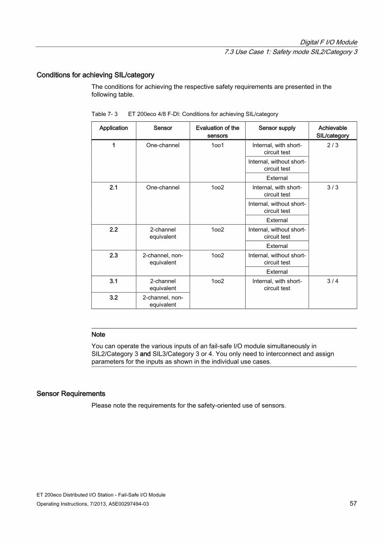
Conditions for achieving SIL/category The conditions for achieving the respective safety requirements are presented in the following table.
Table 7- 3 ET 200eco 4/8 F-DI: Conditions for achieving SIL/category
Application Sensor Evaluation of the sensors
Sensor supply Achievable SIL/category
1 One-channel 1oo1 Internal, with short-circuit test
2 / 3
Internal, without short-circuit test External
2.1 One-channel 1oo2 Internal, with short-circuit test
3 / 3
Internal, without short-circuit test External
2.2 2-channel equivalent
1oo2 Internal, without short-circuit test External
2.3 2-channel, non-equivalent
1oo2 Internal, without short-circuit test External
3.1 2-channel equivalent
1oo2 Internal, with short-circuit test
3 / 4
3.2 2-channel, non-equivalent
Note
You can operate the various inputs of an fail-safe I/O module simultaneously in SIL2/Category 3 and SIL3/Category 3 or 4. You only need to interconnect and assign parameters for the inputs as shown in the individual use cases.
Sensor Requirements Please note the requirements for the safety-oriented use of sensors.
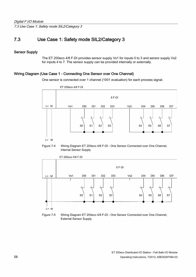
Digital F I/O Module 7.3 Use Case 1: Safety mode SIL2/Category 3
ET 200eco Distributed I/O Station - Fail-Safe I/O Module 58 Operating Instructions, 7/2013, A5E00297494-03
7.3 Use Case 1: Safety mode SIL2/Category 3
Sensor Supply The ET 200eco 4/8 F-DI provides sensor supply Vs1 for inputs 0 to 3 and sensor supply Vs2 for inputs 4 to 7. The sensor supply can be provided internally or externally.
Wiring Diagram (Use Case 1 - Connecting One Sensor over One Channel) One sensor is connected over 1 channel (1001 evaluation) for each process signal.
Figure 7-4 Wiring Diagram ET 200eco 4/8 F-DI - One Sensor Connected over One Channel,
Internal Sensor Supply
Figure 7-5 Wiring Diagram ET 200eco 4/8 F-DI - One Sensor Connected over One Channel,
External Sensor Supply

Digital F I/O Module 7.4 Use Case 2: Safety mode SIL3/Category 3
ET 200eco Distributed I/O Station - Fail-Safe I/O Module Operating Instructions, 7/2013, A5E00297494-03 59
Assignable Parameters (Use Case 1) Set the parameter "Evaluation of sensor" to "1oo1 evaluation" for the respective input.
You can activate or deactivate the "short-circuit test" parameter. However, you must deactivate the short-circuit test as soon as one or more fail-safe digital inputs are externally supplied. Otherwise the "short circuit" diagnosis may be reported.
Special Features of Fault Detection (Application 1) The following table shows fault detection according to the sensor supply and the parameter assignment for the short-circuit test:
Table 7- 4 ET 200eco 4/8 F-DI: Fault Detection (Use Case 1)
Example of Error Fault detection when ...
Internal sensor power supply and activated
short-circuit test
Internal Sensor Supply and
Deactivated Short-Circuit Test
External Sensor Supply
Short circuit in DI 0 with DI 1 No No No Short circuit in DI 0 with DI 4 Yes* No No P-short circuit in DI 0 Yes No No M-short circuit in DI 0 Yes* Yes* No Discrepancy error – – – P short-circuit in sensor supply 1
Yes No No
M-short circuit in sensor supply 1 or sensor supply defective
Yes Yes Yes
Short circuit in sensor supply 1 with sensor supply 2
Yes No No
Error in read/test circuit Yes Yes Yes Supply voltage fault Yes Yes Yes * Fault is detected only in case of signal corruption. In other words, the signal read differs from the sensor signal. If there is no signal corruption with respect to the sensor signal, error detection is not possible and is not required from a safety standpoint.
Digital F I/O Module 7.4 Use Case 2: Safety mode SIL3/Category 3
ET 200eco Distributed I/O Station - Fail-Safe I/O Module 60 Operating Instructions, 7/2013, A5E00297494-03
7.4 Use Case 2: Safety mode SIL3/Category 3
Assigning inputs to each other The ET 200eco 4/8 F-DI has 8 fail-safe inputs DI 0 to DI 7 (SIL2). Two inputs each can be used as one input (SIL3). The following assignment applies:
DI 0 with DI 4
DI 1 with DI 5
DI 2 with DI 6
DI 3 with DI 7
Sensor supply The ET 200eco 4/8 F-DI provides sensor supply Vs1 for inputs 0 to 3 and sensor supply Vs2 for inputs 4 to 7. The sensor power supply can be provided internally or externally.
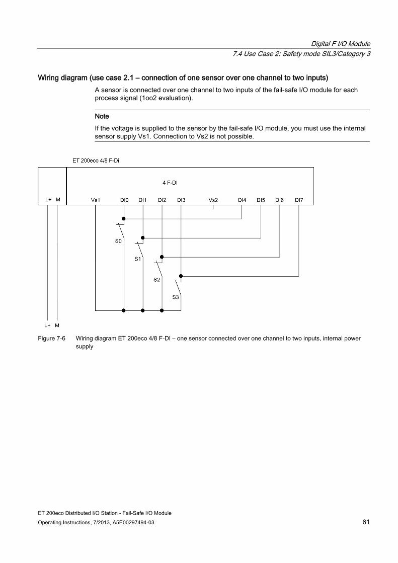
Digital F I/O Module 7.4 Use Case 2: Safety mode SIL3/Category 3
ET 200eco Distributed I/O Station - Fail-Safe I/O Module Operating Instructions, 7/2013, A5E00297494-03 61
Wiring diagram (use case 2.1 – connection of one sensor over one channel to two inputs) A sensor is connected over one channel to two inputs of the fail-safe I/O module for each process signal (1oo2 evaluation).
Note
If the voltage is supplied to the sensor by the fail-safe I/O module, you must use the internal sensor supply Vs1. Connection to Vs2 is not possible.
Figure 7-6 Wiring diagram ET 200eco 4/8 F-DI – one sensor connected over one channel to two inputs, internal power
supply

Digital F I/O Module 7.4 Use Case 2: Safety mode SIL3/Category 3
ET 200eco Distributed I/O Station - Fail-Safe I/O Module 62 Operating Instructions, 7/2013, A5E00297494-03
Figure 7-7 Wiring diagram ET 200eco 4/8 F-DI – one sensor connected over one channel to two inputs, external power
supply
WARNING
To achieve SIL3/Category 3 using this wiring, you must use a suitably qualified sensor.
Configurable parameters (use case 2.1) Set the parameter "Evaluation of the sensors" to "1oo2 evaluation" and the parameter "Type of sensor interconnection" to "1-channel" for the relevant input. The discrepancy time is preset to 10 ms and cannot be changed.
You can activate or deactivate the "short-circuit test" parameter. However, you must deactivate the short-circuit test as soon as one or more fail-safe digital inputs are externally supplied. Otherwise the "short circuit" diagnosis may be reported.
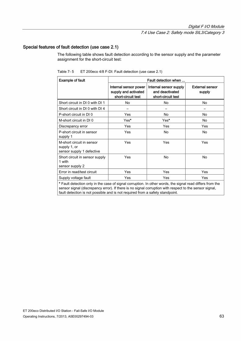
Digital F I/O Module 7.4 Use Case 2: Safety mode SIL3/Category 3
ET 200eco Distributed I/O Station - Fail-Safe I/O Module Operating Instructions, 7/2013, A5E00297494-03 63
Special features of fault detection (use case 2.1) The following table shows fault detection according to the sensor supply and the parameter assignment for the short-circuit test:
Table 7- 5 ET 200eco 4/8 F-DI: Fault detection (use case 2.1)
Example of fault Fault detection when ...
Internal sensor power supply and activated
short-circuit test
Internal sensor supply and deactivated short-circuit test
External sensor supply
Short circuit in DI 0 with DI 1 No No No Short circuit in DI 0 with DI 4 – – – P-short circuit in DI 0 Yes No No M-short circuit in DI 0 Yes* Yes* No Discrepancy error Yes Yes Yes P-short circuit in sensor supply 1
Yes No No
M-short circuit in sensor supply 1, or sensor supply 1 defective
Yes Yes Yes
Short circuit in sensor supply 1 with sensor supply 2
Yes No No
Error in read/test circuit Yes Yes Yes Supply voltage fault Yes Yes Yes * Fault detection only in the case of signal corruption. In other words, the signal read differs from the sensor signal (discrepancy error). If there is no signal corruption with respect to the sensor signal, fault detection is not possible and is not required from a safety standpoint.
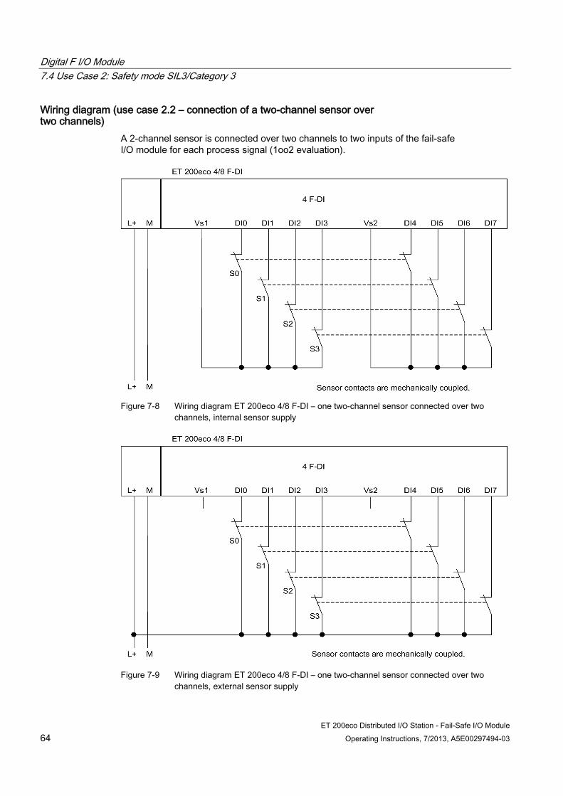
Digital F I/O Module 7.4 Use Case 2: Safety mode SIL3/Category 3
ET 200eco Distributed I/O Station - Fail-Safe I/O Module 64 Operating Instructions, 7/2013, A5E00297494-03
Wiring diagram (use case 2.2 – connection of a two-channel sensor over two channels)
A 2-channel sensor is connected over two channels to two inputs of the fail-safe I/O module for each process signal (1oo2 evaluation).
Figure 7-8 Wiring diagram ET 200eco 4/8 F-DI – one two-channel sensor connected over two
channels, internal sensor supply
Figure 7-9 Wiring diagram ET 200eco 4/8 F-DI – one two-channel sensor connected over two
channels, external sensor supply
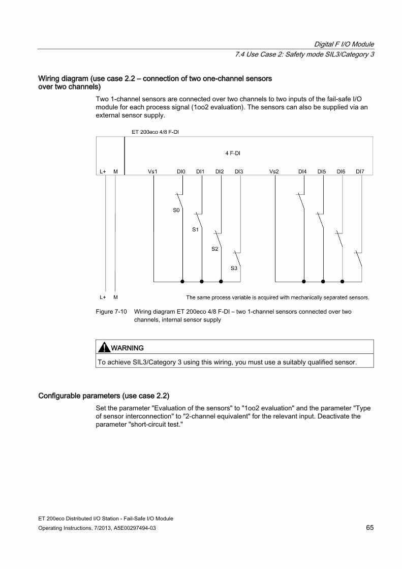
Digital F I/O Module 7.4 Use Case 2: Safety mode SIL3/Category 3
ET 200eco Distributed I/O Station - Fail-Safe I/O Module Operating Instructions, 7/2013, A5E00297494-03 65
Wiring diagram (use case 2.2 – connection of two one-channel sensors over two channels)
Two 1-channel sensors are connected over two channels to two inputs of the fail-safe I/O module for each process signal (1oo2 evaluation). The sensors can also be supplied via an external sensor supply.
Figure 7-10 Wiring diagram ET 200eco 4/8 F-DI – two 1-channel sensors connected over two
channels, internal sensor supply
WARNING
To achieve SIL3/Category 3 using this wiring, you must use a suitably qualified sensor.
Configurable parameters (use case 2.2) Set the parameter "Evaluation of the sensors" to "1oo2 evaluation" and the parameter "Type of sensor interconnection" to "2-channel equivalent" for the relevant input. Deactivate the parameter "short-circuit test."

Digital F I/O Module 7.4 Use Case 2: Safety mode SIL3/Category 3
ET 200eco Distributed I/O Station - Fail-Safe I/O Module 66 Operating Instructions, 7/2013, A5E00297494-03
Special features of fault detection (use case 2.2) The following table shows fault detection according to the sensor supply and the parameter assignment for the short-circuit test:
Table 7- 6 ET 200eco 4/8 F-DI: Fault detection (use case 2.2)
Example of fault Fault detection when ...
Internal sensor supply and deactivated short-circuit test
External sensor supply
Short circuit in DI 0 with DI 1 No No Short circuit in DI 0 with DI 4 No No P-short circuit in DI 0 No No M-short circuit in DI 0 Yes* No Discrepancy error Yes Yes P-short circuit in sensor supply 1 No No M-short circuit in sensor supply 1, or sensor supply 1 defective
Yes Yes
Short circuit in sensor supply 1 with sensor supply 2
No No
Error in read/test circuit Yes Yes Supply voltage fault Yes Yes * Fault detection only in the case of signal corruption. In other words, the signal read differs from the sensor signal (discrepancy error). If there is no signal corruption with respect to the sensor signal, fault detection is not possible and is not required from a safety standpoint.

Digital F I/O Module 7.4 Use Case 2: Safety mode SIL3/Category 3
ET 200eco Distributed I/O Station - Fail-Safe I/O Module Operating Instructions, 7/2013, A5E00297494-03 67
Wiring diagram (use case 2.3 – two-channel, non-equivalent connection of a non-equivalent sensor)
A non-equivalent sensor is connected over two channels for non-equivalence to two inputs of the fail-safe I/O module for each process signal (1oo2 evaluation). The upper channels on the fail-safe I/O module (DI0 through DI3) supply the user signals. If no faults are detected, these signals will be available in the I/O area for inputs on the F-CPU.
Note
If the voltage is supplied to the sensor by the fail-safe I/O module, you must use the internal sensor supply Vs1. Connection to Vs2 is not possible.
Figure 7-11 Wiring diagram ET 200eco 4/8 F-DI – one non-equivalent sensor connected over two
channels (for non-equivalence), internal sensor supply
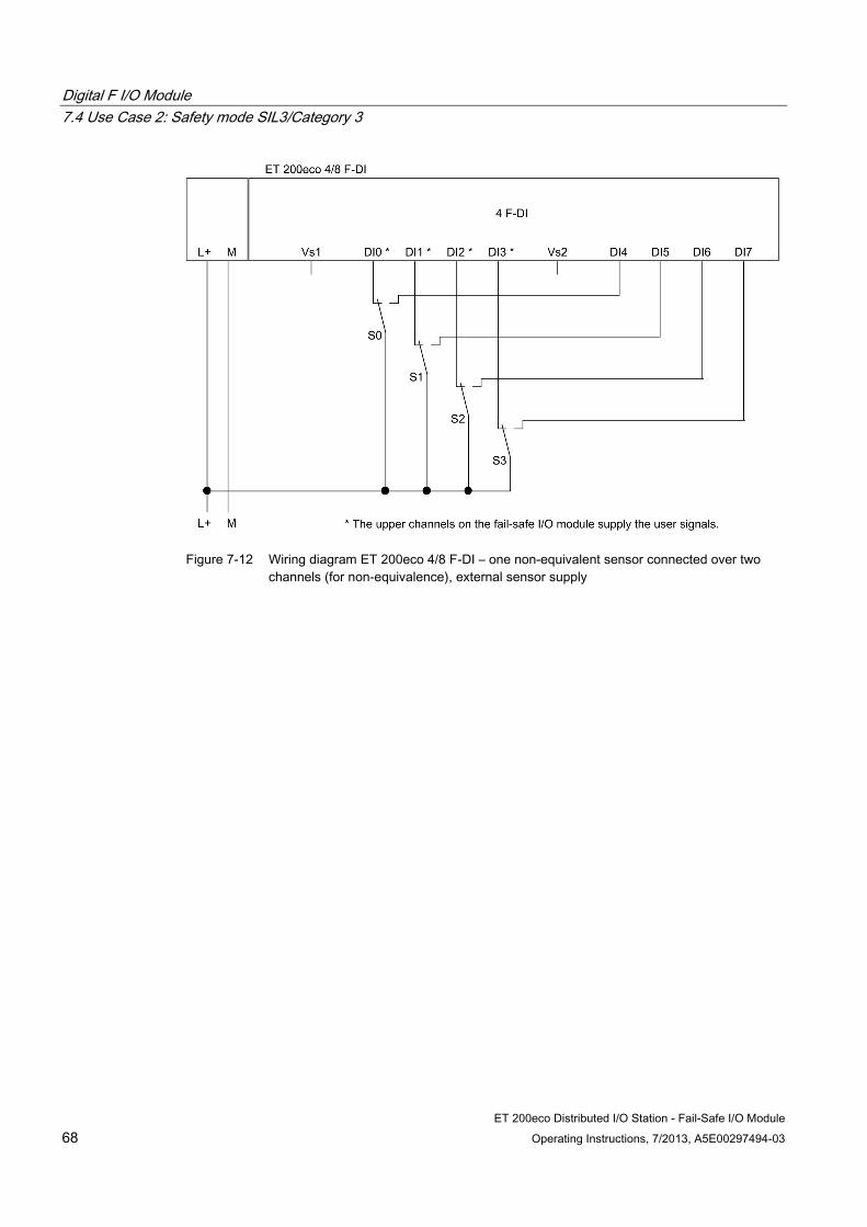
Digital F I/O Module 7.4 Use Case 2: Safety mode SIL3/Category 3
ET 200eco Distributed I/O Station - Fail-Safe I/O Module 68 Operating Instructions, 7/2013, A5E00297494-03
Figure 7-12 Wiring diagram ET 200eco 4/8 F-DI – one non-equivalent sensor connected over two
channels (for non-equivalence), external sensor supply

Digital F I/O Module 7.4 Use Case 2: Safety mode SIL3/Category 3
ET 200eco Distributed I/O Station - Fail-Safe I/O Module Operating Instructions, 7/2013, A5E00297494-03 69
Wiring diagram (use case 2.3 – connection of two one-channel sensors over two channels for non-equivalence)
Two 1-channel sensors are connected for non-equivalence over two channels to two inputs of the fail-safe I/O module for each process signal (1oo2 evaluation). The sensors can also be supplied via an external sensor supply.
Figure 7-13 Wiring diagram ET 200eco 4/8 F-DI – two one-channel sensors connected over two
channels for non-equivalence, internal sensor supply
WARNING
To achieve SIL3/Category 3 using this wiring, you must use a suitably qualified sensor.
Configurable parameters (use case 2.3) Set the parameter "Evaluation of the sensors" to "1oo2 evaluation" and the parameter "Type of sensor interconnection" to "2-channel non-equivalent" for the relevant input. Deactivate the parameter "short-circuit test."
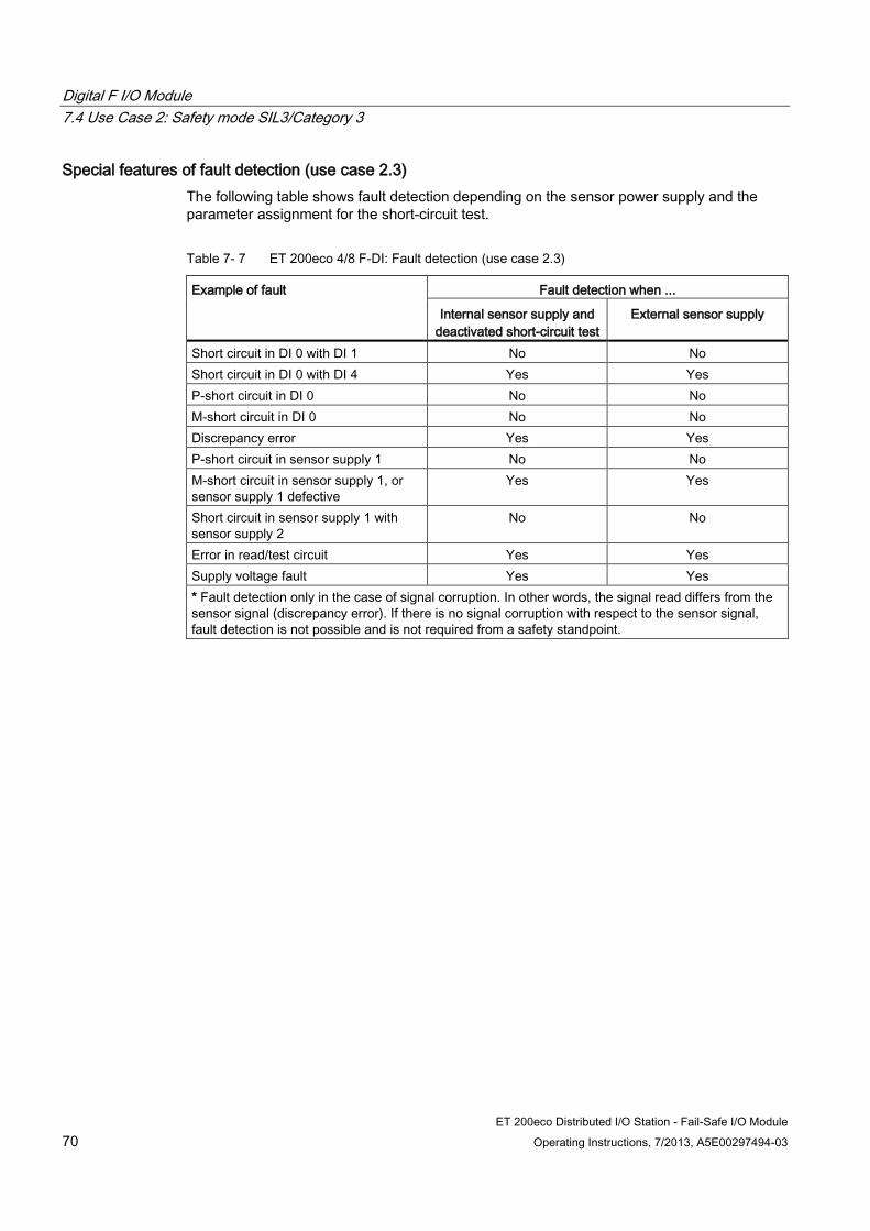
Digital F I/O Module 7.4 Use Case 2: Safety mode SIL3/Category 3
ET 200eco Distributed I/O Station - Fail-Safe I/O Module 70 Operating Instructions, 7/2013, A5E00297494-03
Special features of fault detection (use case 2.3) The following table shows fault detection depending on the sensor power supply and the parameter assignment for the short-circuit test.
Table 7- 7 ET 200eco 4/8 F-DI: Fault detection (use case 2.3)
Example of fault Fault detection when ...
Internal sensor supply and deactivated short-circuit test
External sensor supply
Short circuit in DI 0 with DI 1 No No Short circuit in DI 0 with DI 4 Yes Yes P-short circuit in DI 0 No No M-short circuit in DI 0 No No Discrepancy error Yes Yes P-short circuit in sensor supply 1 No No M-short circuit in sensor supply 1, or sensor supply 1 defective
Yes Yes
Short circuit in sensor supply 1 with sensor supply 2
No No
Error in read/test circuit Yes Yes Supply voltage fault Yes Yes * Fault detection only in the case of signal corruption. In other words, the signal read differs from the sensor signal (discrepancy error). If there is no signal corruption with respect to the sensor signal, fault detection is not possible and is not required from a safety standpoint.
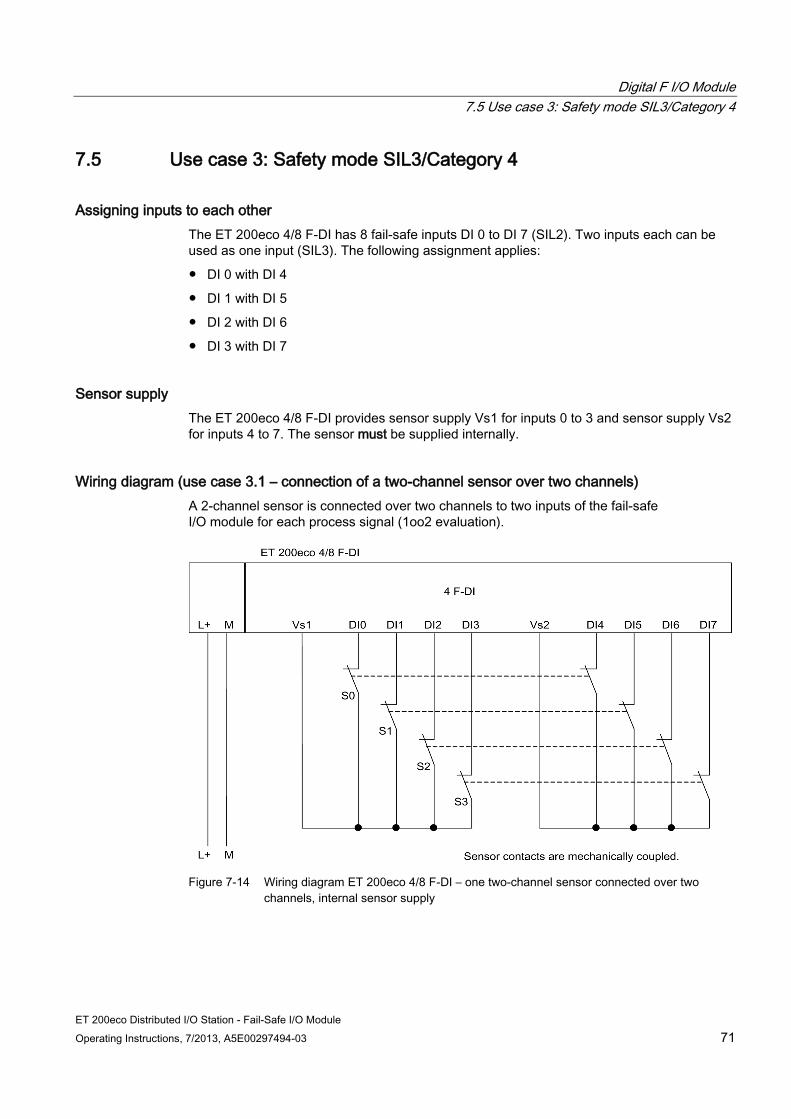
Digital F I/O Module 7.5 Use case 3: Safety mode SIL3/Category 4
ET 200eco Distributed I/O Station - Fail-Safe I/O Module Operating Instructions, 7/2013, A5E00297494-03 71
7.5 Use case 3: Safety mode SIL3/Category 4
Assigning inputs to each other The ET 200eco 4/8 F-DI has 8 fail-safe inputs DI 0 to DI 7 (SIL2). Two inputs each can be used as one input (SIL3). The following assignment applies:
DI 0 with DI 4
DI 1 with DI 5
DI 2 with DI 6
DI 3 with DI 7
Sensor supply The ET 200eco 4/8 F-DI provides sensor supply Vs1 for inputs 0 to 3 and sensor supply Vs2 for inputs 4 to 7. The sensor must be supplied internally.
Wiring diagram (use case 3.1 – connection of a two-channel sensor over two channels) A 2-channel sensor is connected over two channels to two inputs of the fail-safe I/O module for each process signal (1oo2 evaluation).
Figure 7-14 Wiring diagram ET 200eco 4/8 F-DI – one two-channel sensor connected over two
channels, internal sensor supply
Digital F I/O Module 7.5 Use case 3: Safety mode SIL3/Category 4
ET 200eco Distributed I/O Station - Fail-Safe I/O Module 72 Operating Instructions, 7/2013, A5E00297494-03
As an alternative, you can connect two 1-channel sensors over two channels (see wiring diagram for use case 2.2 - connecting two 1-channel sensors over two channels). In this case, the same process variable is acquired with two mechanically separate sensors.
WARNING
To achieve SIL3/Category 4 using this wiring, you must use a suitably qualified sensor.
Configurable parameters (use case 3.1) Set the parameter "Evaluation of the sensors" to "1oo2 evaluation" and the parameter "Type of sensor interconnection" to "2-channel equivalent" for the relevant input. Activate the "short circuit test" parameter.

Digital F I/O Module 7.5 Use case 3: Safety mode SIL3/Category 4
ET 200eco Distributed I/O Station - Fail-Safe I/O Module Operating Instructions, 7/2013, A5E00297494-03 73
Wiring diagram (use case 3.2 – two-channel, non-equivalent connection of a non-equivalent sensor)
A non-equivalent sensor is connected over two channels to two inputs of the fail-safe I/O module for each process signal (1oo2 evaluation).
The upper channels on the fail-safe I/O module (DI0 through DI3) supply the user signals. If no faults are detected, these signals will be available in the I/O area for inputs on the F-CPU.
Note
You must use the internal sensor supply Vs1 to supply voltage to the sensor. Connection to Vs2 is not possible.
Figure 7-15 Wiring diagram ET 200eco 4/8 F-DI – one non-equivalent sensor connected over two
channels (for non-equivalence), internal sensor supply
As an alternative, you can connect two one-channel sensors over two channels for non-equivalence (see wiring diagram for use case 2.3 - connecting two one-channel sensors over two channels for non-equivalence). In this case, the same process variable is acquired with two mechanically separate sensors.
WARNING
To achieve SIL3/Category 4 using this wiring, you must use a suitably qualified sensor.
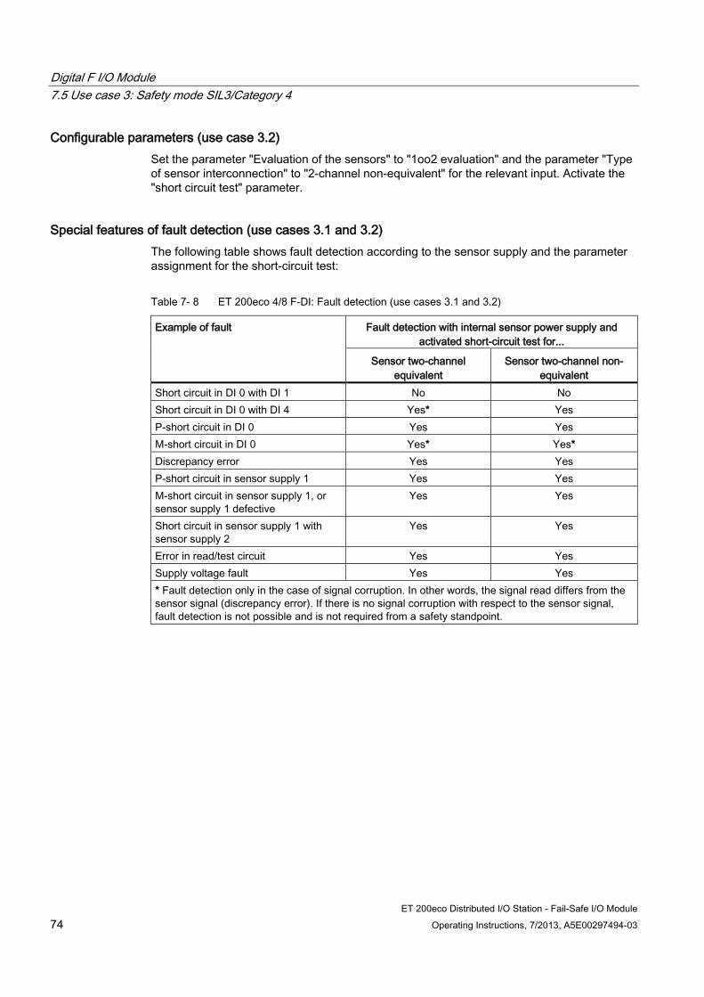
Digital F I/O Module 7.5 Use case 3: Safety mode SIL3/Category 4
ET 200eco Distributed I/O Station - Fail-Safe I/O Module 74 Operating Instructions, 7/2013, A5E00297494-03
Configurable parameters (use case 3.2) Set the parameter "Evaluation of the sensors" to "1oo2 evaluation" and the parameter "Type of sensor interconnection" to "2-channel non-equivalent" for the relevant input. Activate the "short circuit test" parameter.
Special features of fault detection (use cases 3.1 and 3.2) The following table shows fault detection according to the sensor supply and the parameter assignment for the short-circuit test:
Table 7- 8 ET 200eco 4/8 F-DI: Fault detection (use cases 3.1 and 3.2)
Example of fault Fault detection with internal sensor power supply and activated short-circuit test for...
Sensor two-channel equivalent
Sensor two-channel non-equivalent
Short circuit in DI 0 with DI 1 No No Short circuit in DI 0 with DI 4 Yes* Yes P-short circuit in DI 0 Yes Yes M-short circuit in DI 0 Yes* Yes* Discrepancy error Yes Yes P-short circuit in sensor supply 1 Yes Yes M-short circuit in sensor supply 1, or sensor supply 1 defective
Yes Yes
Short circuit in sensor supply 1 with sensor supply 2
Yes Yes
Error in read/test circuit Yes Yes Supply voltage fault Yes Yes * Fault detection only in the case of signal corruption. In other words, the signal read differs from the sensor signal (discrepancy error). If there is no signal corruption with respect to the sensor signal, fault detection is not possible and is not required from a safety standpoint.
Digital F I/O Module 7.5 Use case 3: Safety mode SIL3/Category 4
ET 200eco Distributed I/O Station - Fail-Safe I/O Module Operating Instructions, 7/2013, A5E00297494-03 75
Requirements for machine protection applications with category 4 The following requirements apply for applications in machine protection with category 4:
Wiring between sensors and the automation system and between the automation system and the actuators must be state-of-the-art and must comply with standards for preventing short circuits.
that all short circuits listed in the above table are covered. It is sufficient to locate a short circuit, because two faults are required for it to occur (both shorted signal lines have an isolation fault). A multiple short circuit analysis is not required.
Procedures for locating all short circuits are therefore permissible if single short circuits are not located,
cause corruption of read signals compared to the sensor signals or
cause corruption of read signals compared to sensor signals in the direction that ensures safety.
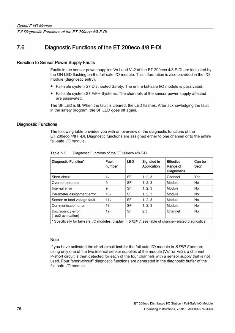
Digital F I/O Module 7.6 Diagnostic Functions of the ET 200eco 4/8 F-DI
ET 200eco Distributed I/O Station - Fail-Safe I/O Module 76 Operating Instructions, 7/2013, A5E00297494-03
7.6 Diagnostic Functions of the ET 200eco 4/8 F-DI
Reaction to Sensor Power Supply Faults Faults in the sensor power supplies Vs1 and Vs2 of the ET 200eco 4/8 F-DI are indicated by the ON LED flashing on the fail-safe I/O module. This information is also provided in the I/O module (diagnostic entry).
Fail-safe system S7 Distributed Safety: The entire fail-safe I/O module is passivated.
Fail-safe system S7 F/FH Systems: The channels of the sensor power supply affected are passivated.
The SF LED is lit. When the fault is cleared, the LED flashes. After acknowledging the fault in the safety program, the SF LED goes off again.
Diagnostic Functions The following table provides you with an overview of the diagnostic functions of the ET 200eco 4/8 F-DI. Diagnostic functions are assigned either to one channel or to the entire fail-safe I/O module.
Table 7- 9 Diagnostic Functions of the ET 200eco 4/8 F-DI
Diagnostic Function* Fault number
LED Signaled in Application
Effective Range of Diagnostics
Can be Set?
Short circuit 1H SF 1, 2, 3 Channel Yes Overtemperature 5H SF 1, 2, 3 Module No Internal error 9H SF 1, 2, 3 Module No Parameter assignment error 10H SF 1, 2, 3 Module No Sensor or load voltage fault 11H SF 1, 2, 3 Module No Communication error 13H SF 1, 2, 3 Module No Discrepancy error (1oo2 evaluation)
19H SF 2,3 Channel No
* Specifically for fail-safe I/O modules; display in STEP 7, see table of channel-related diagnostics.
Note
If you have activated the short-circuit test for the fail-safe I/O module in STEP 7 and are using only one of the two internal sensor supplies of the module (Vs1 or Vs2), a channel P-short circuit is then detected for each of the four channels with a sensor supply that is not used. Four "short-circuit" diagnostic functions are generated in the diagnostic buffer of the fail-safe I/O module.
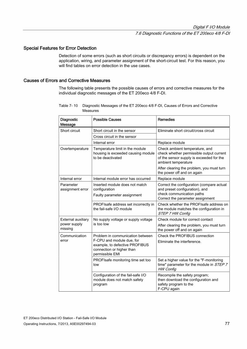
Digital F I/O Module 7.6 Diagnostic Functions of the ET 200eco 4/8 F-DI
ET 200eco Distributed I/O Station - Fail-Safe I/O Module Operating Instructions, 7/2013, A5E00297494-03 77
Special Features for Error Detection Detection of some errors (such as short circuits or discrepancy errors) is dependent on the application, wiring, and parameter assignment of the short-circuit test. For this reason, you will find tables on error detection in the use cases.
Causes of Errors and Corrective Measures The following table presents the possible causes of errors and corrective measures for the individual diagnostic messages of the ET 200eco 4/8 F-DI.
Table 7- 10 Diagnostic Messages of the ET 200eco 4/8 F-DI, Causes of Errors and Corrective Measures
Diagnostic Message
Possible Causes Remedies
Short circuit Short circuit in the sensor Eliminate short circuit/cross circuit Cross circuit in the sensor Internal error Replace module
Overtemperature Temperature limit in the module housing is exceeded causing module to be deactivated
Check ambient temperature, and check whether permissible output current of the sensor supply is exceeded for the ambient temperature After clearing the problem, you must turn the power off and on again
Internal error Internal module error has occurred Replace module Parameter assignment error
Inserted module does not match configuration Faulty parameter assignment
Correct the configuration (compare actual and preset configuration), and check communication paths Correct the parameter assignment
PROFIsafe address set incorrectly in the fail-safe I/O module
Check whether the PROFIsafe address on the module matches the configuration in STEP 7 HW Config
External auxiliary power supply missing
No supply voltage or supply voltage is too low
Check module for correct contact After clearing the problem, you must turn the power off and on again
Communication error
Problem in communication between F-CPU and module due, for example, to defective PROFIBUS connection or higher than permissible EMI
Check the PROFIBUS connection Eliminate the interference.
PROFIsafe monitoring time set too low
Set a higher value for the "F-monitoring time" parameter for the module in STEP 7 HW Config
Configuration of the fail-safe I/O module does not match safety program
Recompile the safety program; then download the configuration and safety program to the F-CPU again
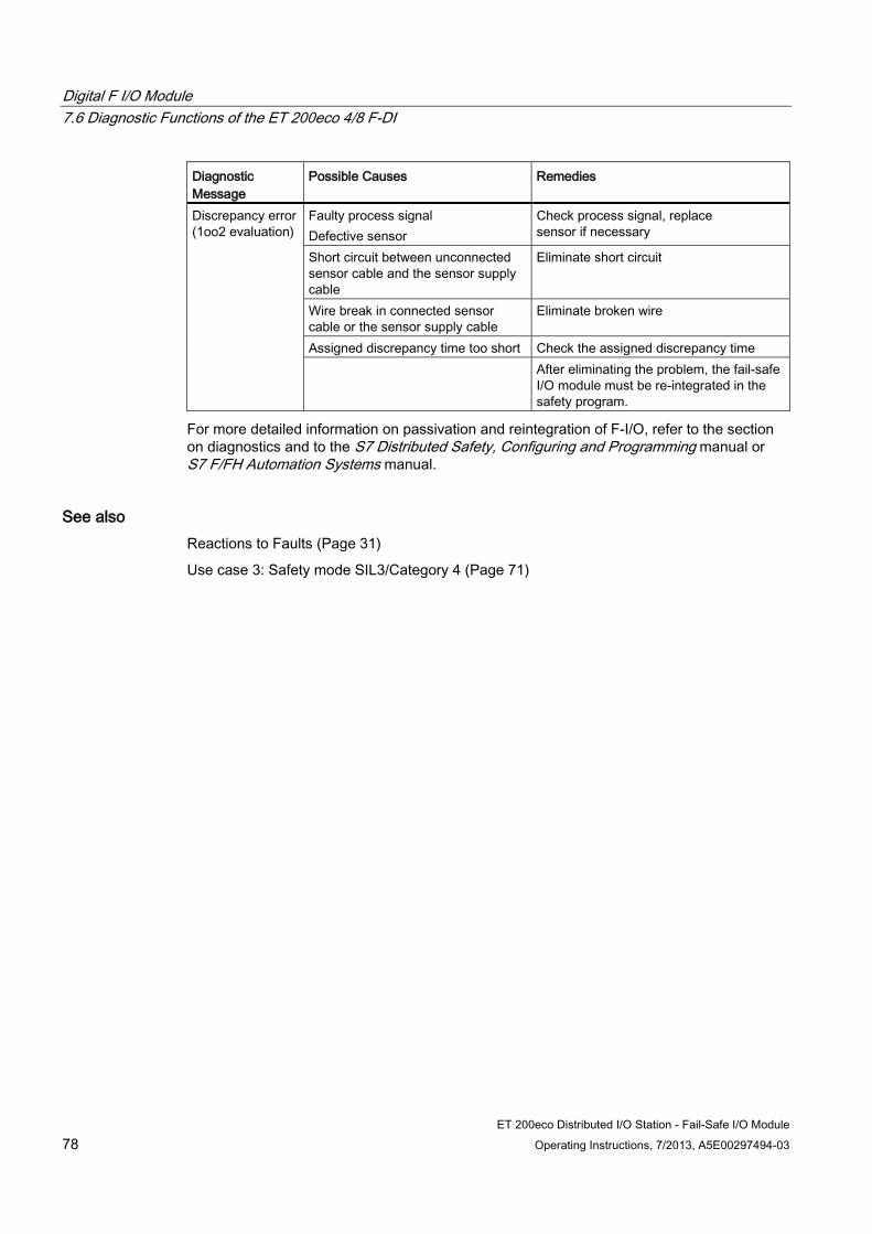
Digital F I/O Module 7.6 Diagnostic Functions of the ET 200eco 4/8 F-DI
ET 200eco Distributed I/O Station - Fail-Safe I/O Module 78 Operating Instructions, 7/2013, A5E00297494-03
Diagnostic Message
Possible Causes Remedies
Discrepancy error (1oo2 evaluation)
Faulty process signal Defective sensor
Check process signal, replace sensor if necessary
Short circuit between unconnected sensor cable and the sensor supply cable
Eliminate short circuit
Wire break in connected sensor cable or the sensor supply cable
Eliminate broken wire
Assigned discrepancy time too short Check the assigned discrepancy time After eliminating the problem, the fail-safe
I/O module must be re-integrated in the safety program.
For more detailed information on passivation and reintegration of F-I/O, refer to the section on diagnostics and to the S7 Distributed Safety, Configuring and Programming manual or S7 F/FH Automation Systems manual.
See also Reactions to Faults (Page 31)
Use case 3: Safety mode SIL3/Category 4 (Page 71)
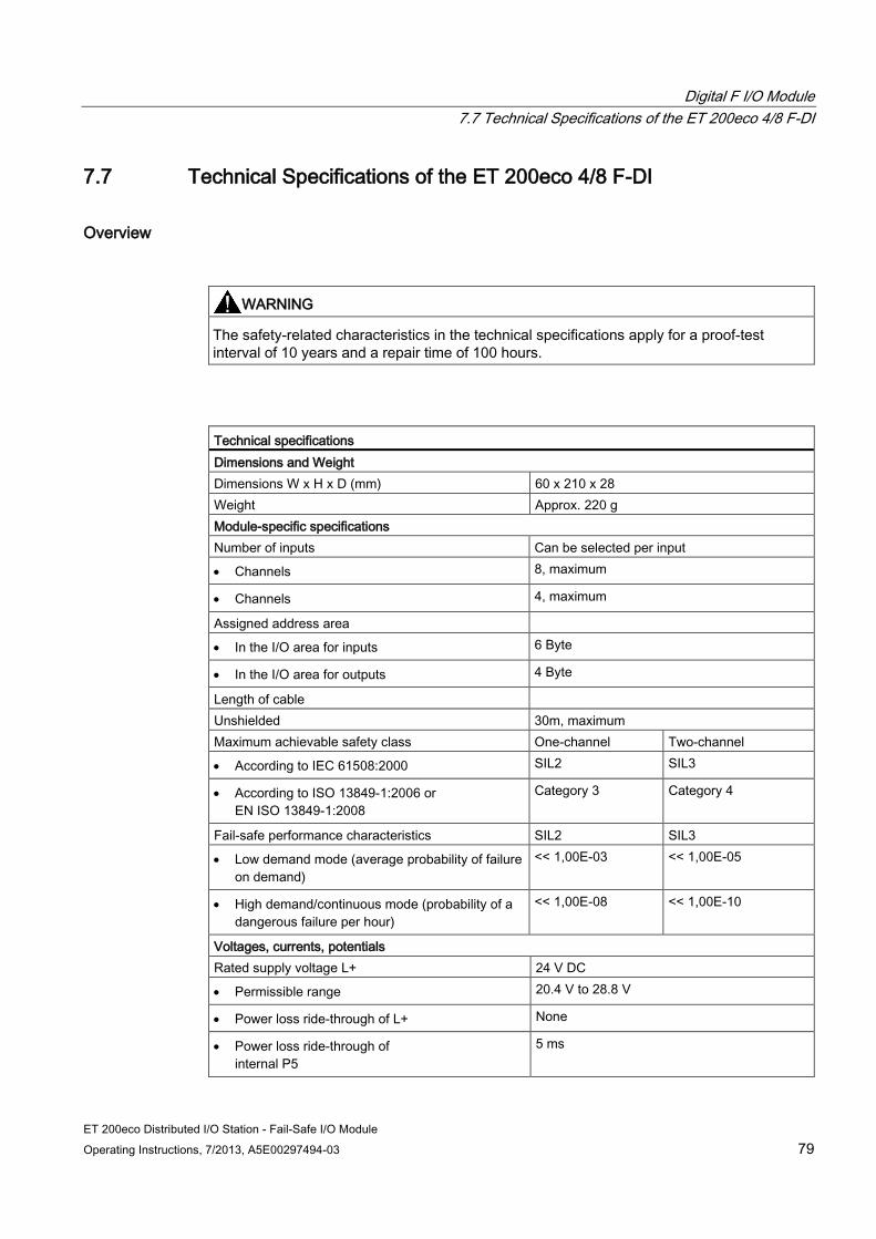
Digital F I/O Module 7.7 Technical Specifications of the ET 200eco 4/8 F-DI
ET 200eco Distributed I/O Station - Fail-Safe I/O Module Operating Instructions, 7/2013, A5E00297494-03 79
7.7 Technical Specifications of the ET 200eco 4/8 F-DI
Overview
WARNING
The safety-related characteristics in the technical specifications apply for a proof-test interval of 10 years and a repair time of 100 hours.
Technical specifications Dimensions and Weight Dimensions W x H x D (mm) 60 x 210 x 28 Weight Approx. 220 g Module-specific specifications Number of inputs Can be selected per input
• Channels 8, maximum
• Channels 4, maximum
Assigned address area
• In the I/O area for inputs 6 Byte
• In the I/O area for outputs 4 Byte
Length of cable Unshielded 30m, maximum Maximum achievable safety class One-channel Two-channel
• According to IEC 61508:2000 SIL2 SIL3
• According to ISO 13849-1:2006 or EN ISO 13849-1:2008
Category 3 Category 4
Fail-safe performance characteristics SIL2 SIL3
• Low demand mode (average probability of failure on demand)
<< 1,00E-03 << 1,00E-05
• High demand/continuous mode (probability of a dangerous failure per hour)
<< 1,00E-08 << 1,00E-10
Voltages, currents, potentials Rated supply voltage L+ 24 V DC
• Permissible range 20.4 V to 28.8 V
• Power loss ride-through of L+ None
• Power loss ride-through of internal P5
5 ms
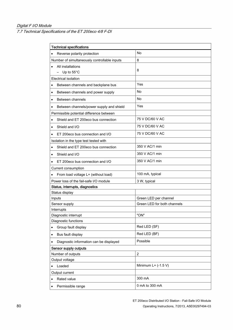
Digital F I/O Module 7.7 Technical Specifications of the ET 200eco 4/8 F-DI
ET 200eco Distributed I/O Station - Fail-Safe I/O Module 80 Operating Instructions, 7/2013, A5E00297494-03
Technical specifications
• Reverse polarity protection No
Number of simultaneously controllable inputs 8
• All installations – Up to 55°C
8
Electrical isolation
• Between channels and backplane bus Yes
• Between channels and power supply No
• Between channels No
• Between channels/power supply and shield Yes
Permissible potential difference between
• Shield and ET 200eco bus connection 75 V DC/60 V AC
• Shield and I/O 75 V DC/60 V AC
• ET 200eco bus connection and I/O 75 V DC/60 V AC
Isolation in the type test tested with
• Shield and ET 200eco bus connection 350 V AC/1 min
• Shield and I/O 350 V AC/1 min
• ET 200eco bus connection and I/O 350 V AC/1 min
Current consumption
• From load voltage L+ (without load) 100 mA, typical
Power loss of the fail-safe I/O module 3 W, typical Status, interrupts, diagnostics Status display Inputs Green LED per channel Sensor supply Green LED for both channels Interrupts Diagnostic interrupt "ON" Diagnostic functions
• Group fault display Red LED (SF)
• Bus fault display Red LED (BF)
• Diagnostic information can be displayed Possible
Sensor supply outputs Number of outputs 2 Output voltage
• Loaded Minimum L+ (-1.5 V)
Output current
• Rated value 300 mA
• Permissible range 0 mA to 300 mA
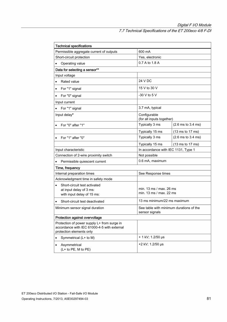
Digital F I/O Module 7.7 Technical Specifications of the ET 200eco 4/8 F-DI
ET 200eco Distributed I/O Station - Fail-Safe I/O Module Operating Instructions, 7/2013, A5E00297494-03 81
Technical specifications Permissible aggregate current of outputs 600 mA Short-circuit protection Yes, electronic
• Operating value 0.7 A to 1.8 A
Data for selecting a sensor** Input voltage
• Rated value 24 V DC
• For "1" signal 15 V to 30 V
• For "0" signal -30 V to 5 V
Input current
• For "1" signal 3.7 mA, typical
Input delay* Configurable (for all inputs together)
• For "0" after "1" Typically 3 ms (2.6 ms to 3.4 ms)
Typically 15 ms (13 ms to 17 ms)
• For "1" after "0" Typically 3 ms (2.6 ms to 3.4 ms)
Typically 15 ms (13 ms to 17 ms) Input characteristic In accordance with IEC 1131, Type 1 Connection of 2-wire proximity switch Not possible
• Permissible quiescent current 0.6 mA, maximum
Time, frequency Internal preparation times See Response times Acknowledgment time in safety mode
• Short-circuit test activated at input delay of 3 ms: with input delay of 15 ms:
min. 13 ms / max. 26 ms min. 13 ms / max. 22 ms
• Short-circuit test deactivated 13 ms minimum/22 ms maximum
Minimum sensor signal duration See table with minimum durations of the sensor signals
Protection against overvoltage Protection of power supply L+ from surge in accordance with IEC 61000-4-5 with external protection elements only
• Symmetrical (L+ to M) + 1 kV; 1.2/50 μs
• Asymmetrical (L+ to PE, M to PE)
+2 kV; 1.2/50 μs
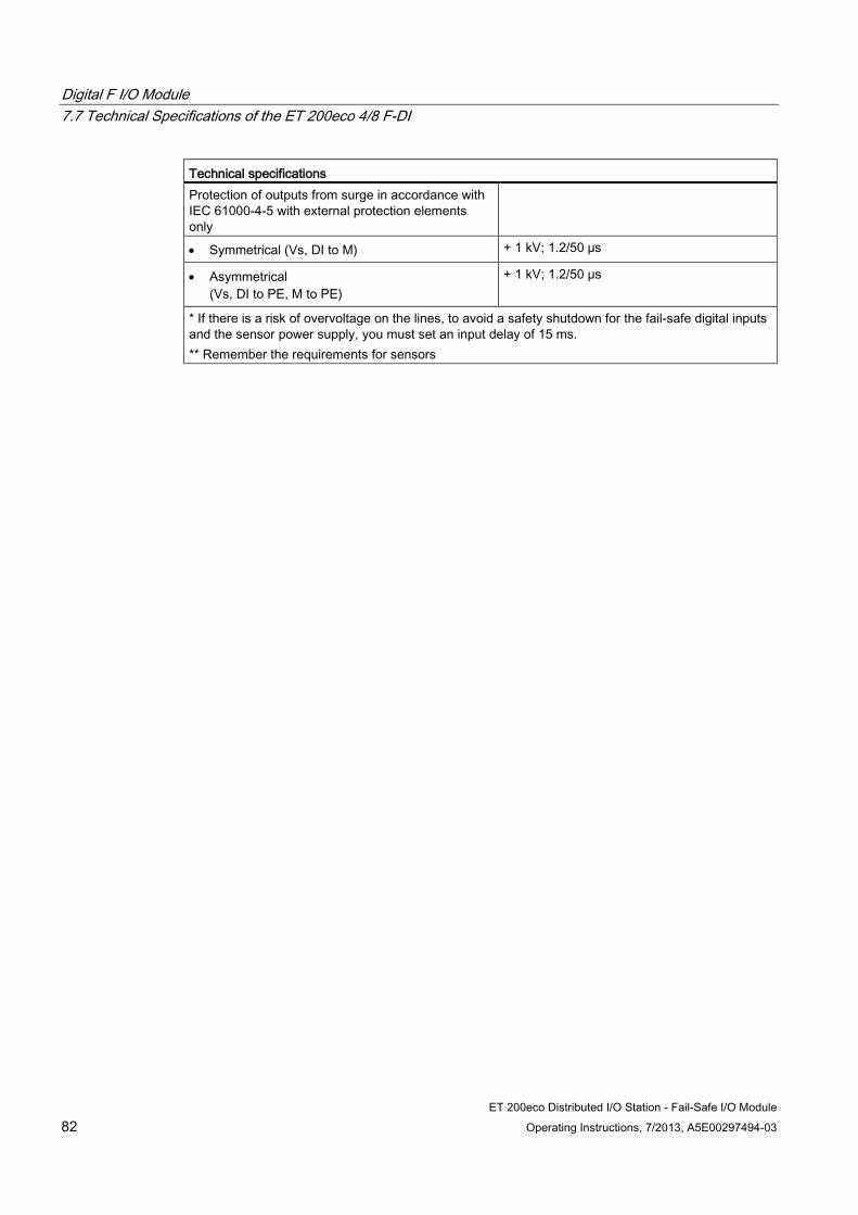
Digital F I/O Module 7.7 Technical Specifications of the ET 200eco 4/8 F-DI
ET 200eco Distributed I/O Station - Fail-Safe I/O Module 82 Operating Instructions, 7/2013, A5E00297494-03
Technical specifications Protection of outputs from surge in accordance with IEC 61000-4-5 with external protection elements only
• Symmetrical (Vs, DI to M) + 1 kV; 1.2/50 μs
• Asymmetrical (Vs, DI to PE, M to PE)
+ 1 kV; 1.2/50 μs
* If there is a risk of overvoltage on the lines, to avoid a safety shutdown for the fail-safe digital inputs and the sensor power supply, you must set an input delay of 15 ms. ** Remember the requirements for sensors
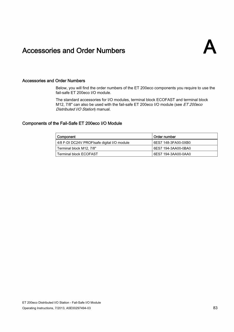
ET 200eco Distributed I/O Station - Fail-Safe I/O Module Operating Instructions, 7/2013, A5E00297494-03 83
Accessories and Order Numbers A
Accessories and Order Numbers Below, you will find the order numbers of the ET 200eco components you require to use the fail-safe ET 200eco I/O module.
The standard accessories for I/O modules, terminal block ECOFAST and terminal block M12, 7/8" can also be used with the fail-safe ET 200eco I/O module (see ET 200eco Distributed I/O Station) manual.
Components of the Fail-Safe ET 200eco I/O Module Component Order number 4/8 F-DI DC24V PROFIsafe digital I/O module 6ES7 148-3FA00-0XB0 Terminal block M12, 7/8" 6ES7 194-3AA00-0BA0 Terminal block ECOFAST 6ES7 194-3AA00-0AA0

Accessories and Order Numbers
ET 200eco Distributed I/O Station - Fail-Safe I/O Module 84 Operating Instructions, 7/2013, A5E00297494-03
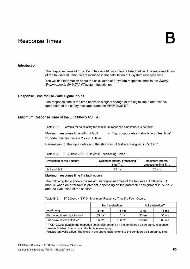
ET 200eco Distributed I/O Station - Fail-Safe I/O Module Operating Instructions, 7/2013, A5E00297494-03 85
Response Times B
Introduction The response times of ET 200eco fail-safe I/O module are listed below. The response times of the fail-safe I/O module are included in the calculation of F-system response time.
You will find information about the calculation of F-system response times in the Safety Engineering in SIMATIC S7 system description.
Response Time for Fail-Safe Digital Inputs The response time is the time between a signal change at the digital input and reliable generation of the safety message frame on PROFIBUS DP.
Maximum Response Time of the ET 200eco 4/8 F-DI
Table B- 1 Formula for calculating the maximum response time if there is no fault:
Maximum response time without fault = Tmax + input delay + short-circuit test time* * Short-circuit test time = 2 x input delay
Parameters for the input delay and the short-circuit test are assigned in STEP 7.
Table B- 2 ET 200eco 4/8 F-DI: Internal Conditioning Times
Evaluation of the Sensors Minimum internal processing time Tmin
Maximum internal processing time Tmax
1v1 and 2v2 13 ms 20 ms
Maximum response time if a fault occurs:
The following table shows the maximum response times of the fail-safe ET 200eco I/O module when an error/fault is present, depending on the parameter assignment in STEP 7 and the evaluation of the sensors.
Table B- 3 ET 200eco 4/8 F-DI: Maximum Response Time if a Fault Occurs:
Input delay
1oo1 evaluation 1v2 evaluation**
3 ms 15 ms 3 ms 15 ms Short-circuit test deactivated 35 ms 47 ms 23 ms 35 ms Short-circuit test activated 55 ms 106 ms 29 ms 65 ms ** With 2v2 evaluation the response times also depend on the configured discrepancy response: Provide 0 value: The times in the table above apply. Provide last valid value: The times in the above table extend to the configured discrepancy time.

Response Times
ET 200eco Distributed I/O Station - Fail-Safe I/O Module 86 Operating Instructions, 7/2013, A5E00297494-03
Note
Please note that the Excel files for calculation of the maximum response times (s7fcotia.xls and s7ftimea.xls) provided with the S7 Distributed Safety and S7 F/FH Systems option packages already supports calculation of the extension of the "Maximum responses time in the event of a fault" by the configured discrepancy time.
See also Fail-Safe ET 200eco I/O Module 4/8 F-DI DC 24V PROFIsafe (Page 49)

ET 200eco Distributed I/O Station - Fail-Safe I/O Module Operating Instructions, 7/2013, A5E00297494-03 87
Glossary
Fail-safe I/O module ET 200eco I/O module that can be used for safety-related operation (in -> safety mode) in the S7 Distributed Safety or S7 F/FH fail-safe systems. This I/O module is equipped with integrated -> safety functions.
F-systems -> Fail-safe systems
Glossary
ET 200eco Distributed I/O Station - Fail-Safe I/O Module 88 Operating Instructions, 7/2013, A5E00297494-03
ET 200eco Distributed I/O Station - Fail-Safe I/O Module Operating Instructions, 7/2013, A5E00297494-03 89
Index
1 1oo1 evaluation
ET 200eco 4/8 F-DI, 58 1oo2 evaluation
ET 200eco 4/8 F-DI, 61, 64, 65, 67, 71, 73
2 2-channel equivalent sensor, 53 2-channel non-equivalent sensor, 53, 73
A Accessories, 83 Acknowledgment time
ET 200eco 4/8 F-DI, 81 Address
PROFIsafe, 22 Address switch
for PROFIsafe addresses, 22 setting, 23
Addresses Occupied by Useful Data, 21 Applications
ET 200eco 4/8 F-DI, 56 Approvals, 3
CE, FM, UL, CSA, cULus, KEMA, 37, 38 Shipbuilding, 39
B Basic knowledge
Required, 3 BF LED, 33 Block Diagram
ET 200eco 4/8 F-DI, 52
C Category (Cat.)
Achievable, 17 Causes of errors
ET 200eco 4/8 F-DI, 77 CE approval, 3, 37 Channel
Deactivated, 31 Channel group error, 31 Channel-related diagnostics
of the fail-safe I/O module, 34 Collection, 4 Commissioning
ET 200eco, 18 Communication error, 27, 35
ET 200eco 4/8 F-DI, 76 Components of the fail-safe ET 200eco, 16 Conditioning time
internal, 85 Configuring
F-I/O modules, 19 Conventions
In this manual, 6 CSA Approval, 38 C-Tick mark, 3 cULus approval, 38, 38
D Deactivated channel, 31 Diagnostic functions, 32
cannot be activated by user, 32 Configurable, 32 Reading, 35
Diagnostic Functions ET 200eco 4/8 F-DI, 76
Diagnostics channel-related, 34 Definition, 32
Discrepancy behavior, 54 Discrepancy error
ET 200eco 4/8 F-DI, 76 Discrepancy time, 55
Effect on reaction time, 55 ET 200eco 4/8 F-DI, 53
Disposal, 6 Documentation
Additional, 4 Duration of sensor signals
Requirement relating to, 29
Index
ET 200eco Distributed I/O Station - Fail-Safe I/O Module 90 Operating Instructions, 7/2013, A5E00297494-03
E Electrical connection, 25 Electromagnetic Compatibility, 41
Retry limit, 20, 41 EMC, 41 Environment-Related requirements
climatic, 47 Mechanical, 46
ET 200eco, 14 ET 200eco 4/8 F-DI
Acknowledgment time, 81 Applications, 56 Block Diagram, 52 Causes of Errors and Corrective Measures, 77 Diagnostic Functions, 76 Fail-safe performance characteristics, 79 Order number, 49 Parameters in STEP 7, 53 Sensor supply, 60, 71 Sensor Supply, 58 Special features for fault detection, 63, 66, 70, 74 Special Features for Fault Detection, 59 Technical specifications, 79 Terminal assignment, 51 Wiring diagram, 61, 64, 65, 67, 71, 73 Wiring Diagram, 58
ET 200eco distributed I/O device, 14
F Fail-safe automation system, 14 Fail-Safe I/O Module, 14 Fail-safe I/O modules
Order number, 3 Fail-safe performance characteristics, 79
ET 200eco 4/8 F-DI, 79 Fault detection
ET 200eco 4/8 F-DI, 59, 63, 66, 70, 74 Fault reaction
of the fail-safe I/O module, 31 Fault/Error types
of the fail-safe I/O module, 35 F-CPU
Address Assignment, 21 F-I/O module, 14
Fault reaction, 31 installing, 23 possible uses, 14 Response Times, 85 wiring, 27
F-I/O modules
Available, 15 Configuration, 19 Parameter Assignment, 19
F-monitoring time ET 200eco 4/8 F-DI, 53
F-system, 14 example configuration, 15
F-Systems, 14 Functional extra low voltage
safe, 25
G General technical specifications, 37 Guide
To manual, 6 Guidelines, 40
H H/F Competence Center, 7
I I/O module
fail-safe, 14 I/O module failure
react to, 35 I/O module fault
Diagnostic message, 35 IEC 61131, 39 Input delay, 85
ET 200eco 4/8 F-DI, 53 Installing
F-I/O module, 23 Interference
pulse-shaped, 41 sinusoidal, 44
Internal conditioning time, 85 Internal error
ET 200eco 4/8 F-DI, 76 react to, 35
IP 65, 48 IP 66, 48 IP 67, 48
Index
ET 200eco Distributed I/O Station - Fail-Safe I/O Module Operating Instructions, 7/2013, A5E00297494-03 91
L LED display
of faults, 33 Line cross section, 25 Load voltage missing, 35
M Machine protection
applications in, 32 Manual
Contents, 6 Marking for Australia, 3 Module diagnostics, 35 Monitoring time
ET 200eco 4/8 F-DI, 53
N NAMUR recommendations
requirements for power supply, 26 Nominal voltages, 47
O ON LED, 33
ET 200eco 4/8 F-DI, 76 One-channel sensor, 53 Optional Package, 19 Order numbers, 83
Fail-safe I/O modules, 3 Overtemperature, 35
ET 200eco 4/8 F-DI, 76 Overvoltage category, 47
P Parameter
ET 200eco 4/8 F-DI, Parameter assignment
F-I/O modules, 19 Parameter assignment error, 35
ET 200eco 4/8 F-DI, 76 Pollution degree, 47 possible uses
F-I/O module, 14 Power failure ride-through, 26 Power supply
Requirement relating to, 26 Probability
hazardous errors, 28 PROFIBUS
Bus parameter settings for PROFIBUS DP, 20 PROFIBUS standard, 39 PROFIsafe
Address, 22, 28 Address assignment, 22
Proof-test interval, 79 Protection class, 47 Pulse-shaped interference, 41 Purpose of this manual, 3
R Radio interference
emission of, 45 Reading
Diagnostic functions, 35 Recycling, 6 References
Additional, 4 Remedies
ET 200eco 4/8 F-DI, 77 Requirements
for sensors, 28 Response time
Effect of the discrepancy time, 55 Response Times
of the fail-safe I/O module, 85 Restart of F-System, 31 Retry limit, 20, 41
S S7 Distributed Safety
example configuration, 15 Optional package, 17 Optional Package, 19
Safe functional extra low voltage, 25 Safe state, 14, 31 Safety class, 56
Achievable, 17 Conditions for achieving levels with ET 200eco 4/8 F-DI, 57
Safety function, 17 Safety message frame, 22 Safety mode, 16, 22 Safety-related shutdown, 35 Saving errors, 31 Scope
Of this manual, 3

Index
ET 200eco Distributed I/O Station - Fail-Safe I/O Module 92 Operating Instructions, 7/2013, A5E00297494-03
Sensor Non-equivalent, 73 Requirement relating to, 28
Sensor evaluation ET 200eco 4/8 F-DI, 53, 59, 62, 65, 69, 72, 74
Sensor interconnection ET 200eco 4/8 F-DI, 53, 65, 69, 74
Sensor or load voltage fault ET 200eco 4/8 F-DI, 76
Sensor signal Requirement for duration, 29
Sensor supply ET 200eco 4/8 F-DI, 60, 62, 71 internal, 53
Sensor Supply ET 200eco 4/8 F-DI, 58, 59
Sensor supply, fault in ET 200eco 4/8 F-DI, 76
Sensor voltage missing, 35 Sensors
externally supplied, 25 Requirement relating to, 28
Service, 8 SF LED, 33 SFC 13, 35 Shipbuilding approval, 39 Short circuit, 35
ET 200eco 4/8 F-DI, 59, 62, 76 Short-circuit test, 29, 32, 85
ET 200eco 4/8 F-DI, 53, 53, 59, 62, 65, 69, 72, 74, 76
Sinusoidal interference, 44 Slave diagnostics, 33
Reading, 35 Standard mode, 16 Standards, 3, 40 Storage conditions, 45 Support, 8
Additional, 6
T Technical specifications
ET 200eco 4/8 F-DI, 79 General, 37
Terminal assignment ET 200eco 4/8 F-DI, 51
Training Center, 7 Transport and storage conditions, 45 TÜV certificate, 40 Type of Protection
IP 65, 48
IP 66, 48 IP 67, 48
U UL approval, 37
V Vibration, 46 Voltages
Nominal, 47
W Wiring
F-I/O modules, 27 Wiring diagram
ET 200eco 4/8 F-DI, 61, 64, 65, 67, 71, 73 Wiring Diagram
ET 200eco 4/8 F-DI, 58