et3 modularity project
DESCRIPTION
Project done during the EPICS II course at Colorado School of Mines. ET3 is a modern transportation concept using maglev technology. This document outlines the proposed design for the systems joints, supports and tubing.TRANSCRIPT

ET3 Modular Tube Plan
Colorado School of Mines
OCTOBER 9, 2013
Design Epics 2 FALL 2013
Section E&F
ROBERT NEUKIRCHNER
EVACUATED TUBE TRANSPORT TECHNOLOGIES
TEAM ENGINEERS:
DAEVIN DEV
GARY NORTH
JOE WAITE
RYAN MAIDHOF
STEVEN HANENBERG
TYLER JOHNSON
December 2, 2013
Mr. Daryl Oster, Founder ET3
5425 County Road 32 Unit 28
Longmont, CO 80504
Dear Mr. Daryl Oster,
We are submitting the attached report for Evacuated Tube Transport Technologies’
modularity project. The purpose of this report is to show Evacuated Tube transport Technologies
Fast Track Tech’s final design for the project, explain our major alternative designs, and provide
a cost estimate for the proposed design. We were asked by Daryl Oster and Jack Panter to design
certain parts of this project in order to improve the modularity of ET3’s new mode of transit [1].
For this project we designed the tube sections, the joints between the tube sections, and the
supports that hold the tube.
The design that our team is proposing consists of three main parts: the tube sections, the
joints, and the supports. The design for each tube section is a hollow cylinder made of ductal®
concrete with grooves for the mag/lev track. There are lips on each end to attach to the joints
between tube sections. Each tube section is connected to the one in front and behind it by a joint.
The joint design is based off of a commercially available pipe joint that allows for axial
expansion and contraction, keeps the tubes airtight, and has the same bending properties of the
tube sections. The support design is basically a tripod with a cradle on the top that holds the tube.
This allows for the ground to move without moving the tube. All of these components were
designed to help make the system as modular, cost effective, and resistant to the elements as
possible.
The team of Fast Track Tech is very thankful to have being given the opportunity to work
on this project, and we are very interested in continuing development of our designs. We would
greatly appreciate any feedback or questions about our proposed designs, and we ask for your
permission to continue with this project. Feel free to contact our team liaison Joe Waite by phone
at 651-808-4258 or by email at [email protected].
Sincerely,
Joe Waite
Cc: Robert Neukirchner
Daevin Dev
Steven Hanenberg
Tyler Johnson
Ryan Maidhof
Gary North

Executive Summary
The purpose of this project was to design certain aspects of Evacuated Tube Transport
Technologies’ new mode of transit in order to improve the modularity of the system [1]. For this
project we designed the tube sections that the capsules will be sent through, the joint sections
that connect the tube sections, and the supports that hold the tube above the ground. Each part
was designed to allow for a capsule with a mass of up to 550 kilograms sent through it at up to
6500 kilometers per hour, and was designed to be easy to remove and replace if needed, resistant
to external environmental factors, and cost efficient [2]. The parts were also designed to be used
in either straight or curved sections.
Our team researched multiple types of piping joints and support designs and considered
many designs for the tube sections before coming up with our final designs for the parts. The
tube section needed to be easy to remove and replace and the right shape for capsules to be sent
through it. Our final design for the tube section was a hollow cylinder with grooves running
through it for the mag/lev track and lips at both ends to attach it to the joint section next to it. The
joint design needed to be airtight, able to expand or contract as the temperature changed, and
have the same bending properties as the tube sections. Our final design for the joint includes a
rubber seal that keeps it airtight while allowing for expansion and compression and includes long
rods made of ductal concrete that surround the joint to give it the same bending properties of the
tube sections. Our support design needed to be able to accommodate shifting land and tidal
movements of the Earth’s crust, and needed to be capable of use over land of varying heights. To
fulfill these requirements, our final support design is a tripod with legs that can be adjusted that
attaches to a cradle which holds the tube above the ground.
The modularity of these designs is their biggest advantage. The tube sections and joints
can be easily removed from the system and replaced and are capable of being used in straight or
curved sections of track. The supports are capable of use in multiple types of land and will
accommodate it when it shifts. All of the designed parts will also hold up under large changes in
temperature, high winds, and other common environmental factors. The designs described in this
report will play a role in shaping what Evacuated Tube Transport Technologies’ final design for
their new mode of transit looks like. Our project will be of huge importance given that this mode
of transit may one day be the most common form of long-distance travel. Our designs will allow
the tube sections, joints, and supports to be as modular as possible.

Table of Contents
List of Tables and Figures…………………………………..……………………………….…..1
Introduction………………………..………………………………………………………….....2
Alternative Designs…………………………………………………………………………...….2
Final Design……………………..……………………………………….……………………….4
Cost Estimate……………………………………………………………….……………...……11
Assembly/Operating Instructions……………………………………………………...………11
Summary………………………………………………………………………………………...12
References……………………………………………………………………...………………..14
Appendices…………………………………………………………………………………..…..16
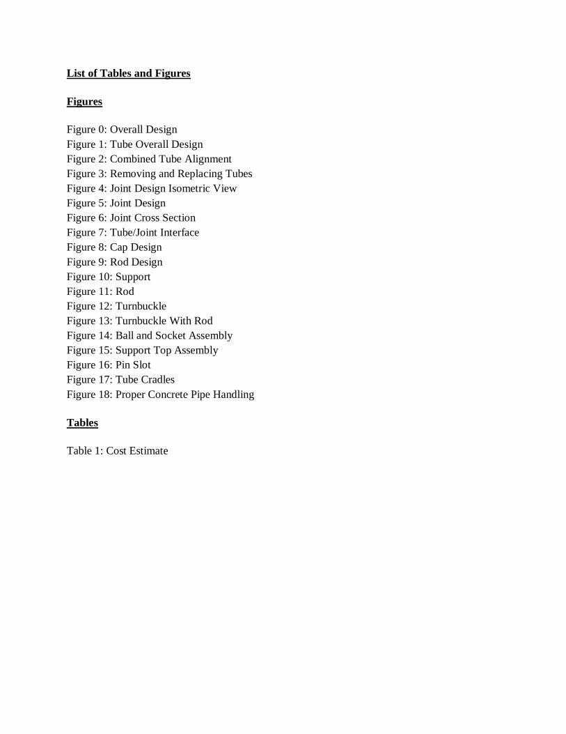
List of Tables and Figures
Figures
Figure 0: Overall Design
Figure 1: Tube Overall Design
Figure 2: Combined Tube Alignment
Figure 3: Removing and Replacing Tubes
Figure 4: Joint Design Isometric View
Figure 5: Joint Design
Figure 6: Joint Cross Section
Figure 7: Tube/Joint Interface
Figure 8: Cap Design
Figure 9: Rod Design
Figure 10: Support
Figure 11: Rod
Figure 12: Turnbuckle
Figure 13: Turnbuckle With Rod
Figure 14: Ball and Socket Assembly
Figure 15: Support Top Assembly
Figure 16: Pin Slot
Figure 17: Tube Cradles
Figure 18: Proper Concrete Pipe Handling
Tables
Table 1: Cost Estimate

Introduction
Fast Track Tech. was asked by Daryl Oster and Jack Panter of Evacuated Tube Transport
Technologies to design certain parts of an Evacuated Transport Tube in order to improve the
modularity of their new mode of transit. Our team must design the tube sections, the joints
between the tube sections, and the supports that hold up the tube to be reliable, durable, cost
effective, and easy to remove and replace [1]. Our design must allow for capsules weighing up to
550 kilograms to be sent through the tube at up to 6500 kilometers per hour and must also
accommodate common environmental factors such as changing temperatures, and shifting land.
The concept for our overall design includes three main parts: the tube sections, the joints, and the
supports. (Figure 0) The tube sections are hollow cylinders made of Ductal concrete with an
outer radius of 1.8 m, a length of 25 m, and a thickness of 2 cm. Each tube has a lip on each end
that allows it to be bolted to a joint. The joint design is similar to the commercially available
pressure piping expansion joint. This design has a rubber seal that will keep the tubes airtight
while also allowing for axial expansion and compression to allow the tubes to expand and
contract under changing temperatures [2]. Our design also has large bolts made of Ductal
concrete that surround the rubber seal to provide structural support. The size and number of these
bolts can be changed in order to change the flexibility of the joints to match that of the tube
sections. The final component of the project, the supports, is designed like a tripod with three
legs that go from the ground to the tube. At the top of the support, is a cradle-like part that holds
the tube allowing the tube to move relative to the supports if the land beneath it shifts.
Alternative Designs
Alternate Tube Designs
1). Fitted End
The fitted end tube design included a cylindrical cuff that has a slightly larger radius than the rest
of the tube located at one end of each tube. The non-cuffed end of one tube would fit into the
cuffed end of the next tube. This design was considered because being able to slide one tube into
the next would create a great amount of structural support. This design would also make it so that
if there was a breakage in one of the seals, there would be less air leakage than with the regular
design in which the ends of the tubes are pressed up against each other. The main flaw with this
design is the difficulty of removing and replacing the tubes. The tubes attached to the front and
back of a tube that needs to be replaced could not simply be moved apart, so it would be
impossible to remove and replace a tube without destroying it.
2). Flat Bottom
This design was one in which the bottom of the inside of the tube was flat instead of round. The
main benefit to this design was that it would make it easier for capsules to merge from one tube
to another at junctions because the capsule would not have to be perfectly aligned with the tube it
was merging into. It would also allow a maintenance shaft to be located between the inside flat
part and the rounded outside of the tube. This design was rejected because the Mag/Lev track

will be strong enough to keep the capsule on the right path whether the bottom of the tube is flat
or round. Also, this design would require the bottom of the capsule to be flat as well, preventing
any cargo or luggage from being stored in the bottom, and would also require more material per
tube to construct.
Alternate Joint Designs
1). Threaded Tube Ends
The threaded tube end design incorporates two concrete tubes having an interlocking design in
which a particular male tube end can be screwed into a female tube end. This would enable an
interlocking tube system that has qualities that are rigid, durable, and cost effective. The strength
of this design is in having a long-lasting connecting potential that is immune to most external
elements and in having minor effect on the overall tube manufacturing process while condensing
the joint and tube manufacturing processes into one process. The weakness of the design is in the
repair process in which it would be required to dismantle multiple sections of tube to repair a
particular section. This design meets the overall criteria of our project in its ability to not be
affected by external elements but has its shortcomings in how tedious and drawn out the repair
process is.
2). Bolt Connector Coupling
The bolt connector design uses an extant bracket with edges, wherein threaded bolt holes are
located, that jut outward perpendicularly to the direction the tube is running. A bracket is fixed to
each end of each tube enabling the brackets to be bolted together. This design enables a tube
system having the tube joints outside the tube. The strength of this design is in having an
expedient and simple installment as well as repair process that are almost identical in nature. The
weakness of this design is in not being able to handle relatively heavy loads, which is crucial due
to the fact that each joint will be located between any given pair of supports. This design meets
the overall criteria of our project in how quickly each section of tube can be connected but has its
fatal flaw in the fact that it is a weak support due to the location of the joints on the tube.
Alternate Support Designs
1). Circle Rotating Around Tube with Piston Base
This design involved a circular collar that would go around the tube. This collar would fit loosely
around the tube, and not actually be attached to it, thus allowing for slight expansion of the tube,
as well as rotation around it and longitudinal movement. Two beams coming off of the collar
would be anchored to the ground independently, and would essentially be large hydraulic shocks.
Thus, when the earth moved, each leg would be able to move independently and the collar would
rotate around the tube. In this way, the tube would not actually move if the earth were to move
sideways – instead, the collar would move around it. The biggest issue with this design was the
complexity of the support beams, which would make it both more expensive and just more
difficult to build. The other problem was that with the supports moving out from under the tube,
there would be a distinct possibility of the tube tipping over the support structure and falling.

2). Alaskan Oil Pipeline
This design mimics that of the supports used to design the Alaskan oil pipeline. There would be
two different types of supports, designated A and B. The A supports would be elaborate pillars,
made utilizing a vertical truss structure. They would surround the pipeline, and would
completely lock it in place. These would allow no movement whatsoever, and would be almost
comparable to setting the tube in a giant block of concrete. The A supports would be few and far
between, essentially serving as bases. There would be more B supports in between each of the A
supports. These would be pillars which the tube would simply rest on top of. There would be
vertical supports on either side of the tube to prevent it from sliding horizontally off the support,
but it would not be otherwise anchored at all, thus allowing for expansion and movement in any
and all directions. The issue with this design was the flex allowance. While the B supports allow
for a lot of flex, the A supports don’t allow any at all. This will mean that these supports will put
major stresses on the tubes because these parts are not given any room to move.
3). Two Fixed Supports
The two fixed supports is a more traditional way of holding something up. this is simply two
solid pillars anchored on one end to the tube, and on the other to the ground. The advantage of
this is that it is very well established, simple and cheap to construct, and has proven durability.
The problem with this is that it does not allow for any flexibility at all. With it being fixed both
at the ground and the tube, there is no way for it to move which means that any ground tremors,
pipe expansion/contraction, or other disruptions will place huge stresses on the tubes and
possibly cause failure. The most important criteria for this support structure is that it must be
able to cope with the movement of the earth and the pipe without causing excessive stresses.
Final Design
Scope of Tube Design
Tube Design Overview
The tube system of the ET3 is responsible for containing and aligning the capsules during travel.
The tubes will join to other tubes using rubber seals and Ductal®
concrete rods. A proper tube
design will ensure a smooth turning along curved banks and smooth travel at high velocities. The
assumption incorporated into this design is that each tube will bend minimally relative to each
other, hence allowing for the tubes to have a slightly bigger diameter lip at end points which
would not constitute a rigid point.
Tube Design Details
The tubes proposed here are round bottomed (circular cross section) with a slightly bigger
diameter lipped end. Each tube section will have a length of 24.81m. When combined with the
tube joint, it will have a combined length of 25m. The circular cross section minimizes stresses

and weights which the tube will have to bear when high speed capsules pass through it. Circular
cross section also allows for easier maneuvering of capsules into different tube branches at high
speeds. The tubes will have a thickness about 0.5inches or 1.27cm. At this thickness, the
production cost is minimized but not at the expense of structural integrity. The interior of the
tube will have two permanent magnetic strips and a linear motor coil running parallel to each
other along the bottom curvature of the tube. (Figure 1) The magnetic strips levitate the capsule
within the tube while the linear motor coil accelerates the capsule along a given distance. The
whole tube will be made of Ductal®
concrete which provides the required amount of flexural and
structural strength needed. Each end of the tube will have a slightly bigger diameter lip. The lips
of the tube will have bolt holes surrounding the lips that allow for the rubber seal to join with the
tube. Long cylindrical Ductal® rods will run directly from one end of the tube to the other,
bypassing the rubber seals, to provide extra structural support and to maintain uniform bending
properties along a combined tube length.
Design Basis
The following criteria were used in analyzing and deciding upon an appropriate design for the
tube. Each criteria is explained in detail below
Capsule Compatibility
The tube design and structure would have to accommodate capsules up to about 1.3m in diameter
and of weights up to 550 kg. As such, the thickness of the tube would have to be significant
enough to handle the stresses produced by that weight. [3] The interior design of the tube would
have to align with the levitation and nitrogen cooling devices on the capsules. Proper alignment
of these devices is crucial for a smooth and safe travel along the tube. (Figure 2) There should
also be empty space between the tube and capsule to avoid contact. [4]
Ease of maintenance
The tube should be easy to remove and replace along any section of the tube system. By having
vertical lips that aren’t fitted ends, any damaged tubes can be vertically removed independently
and replaced by just untightening the bolts and rods. (Figure 3)
Vacuum Load per Linear Length of Tube
Being a vacuum based technology; the tubes would have to be able to withstand external
atmospheric pressures pushing onto the tubes. The vacuum load per unit length is the amount of
stress due to external pressure that is exerted on a unit length of the tube. External pressure
failures can be costly and dangerous. [5] This stress is proportional to the internal diameter of the
tube; which is why a relatively low tube internal diameter of 1.4746m was decided upon.

Calculations show that these stresses are within a safe limit of the allowable stress of Ductal®
concrete at a tube thickness of 0.0127m.
Tube Natural Frequency
Excessive piping/tube vibrations occur when the mechanical natural frequency of the tube is
excited by some pulsations or mechanical forces. Piping vibrations have been causes of major
disasters in industries. The tube natural (vibration) frequency depends purely on material and
geometric properties such as modulus of elasticity, moment of inertia and weight. To avoid
excessive vibrations, it is ideal to minimize the natural frequency. The natural frequency is
proportional to the moment of inertia and inversely proportional to length of individual tube
sections. [6] These are additional reasons for having a small tube thickness of 0.0127m and a
tube length of only 24.81m. Thinner tubes have a lower moment of inertia.
Interfaces
The tubes will be joined to each other via the rubber seals and also by Ductal® concrete rods.
(Figure 2) The rubber seals will meet the tubes at the tube lips on its end points. The tube lips
and rubber lips will have 20 bolts, each having a diameter of 0.02m. The tubes and rubber seal
will be bolted together via the bolts which are made of basalt fiber. To increase structural
integrity and to maintain uniform bending properties, additional Ductal® concrete rods will run
across the rubber seals (bypassing them) from one seal lip to the other. As for the supports, the
tubes will lay directly on top the cradle-like structures of the supports.
Joint Design
Subsystem Overview
This subsystem includes the design and dimensions of the joint section that will be located
between the tubes. The joint will provide structural support between the tubes, maintain the
vacuum inside of them, and allow them to expand and contract under changing temperatures. It
is also designed to have the same flexibility as the tube sections (Figure 4). This design assumes
that the surrounding temperature will never be above the hottest recorded temperature of 58
degrees Celsius or below the lowest recorded temperature (excluding Antarctica) -68 degrees
Celsius [7]. All of the graphics were made to be accurate at a temperature of 20 degrees Celsius.
Subsystem Details
The design for this subsystem was based heavily on the commercially available Series 320 Hand-
Built Pressure Piping Expansion Joint. The inside of the joint has two unconnected, hollow,

coaxial cylinders made of ductal® concrete [8]. There is a small gap between these two cylinders
to allow them to move together and apart as the tube sections expand and contract due to
surrounding temperature changes. These cylinders have a lip on each end that will be bolted to
the lip of the tube sections being connected by the joint (Figure 4 and 5).
There is a Teflon seal that goes around both cylinders to prevent air leakage. 955 Teflon from
Holz rubber is specifically designed for large outdoor seals like the ones incorporated in the
design, and Teflon is immune to many corrosive agents that could destroy other seals.[9] The
middle of the seal has an arch going around its circumference which will allow the joint to
expand and contract as needed without there being a significant resultant axial force. Each side
of the rubber seal is bolted in place between a ring of ductal® concrete and the lip of each side of
the joint to hold it in place using bolts made of basalt rebar (Figure 6). The main purpose of the
cylinders on the inside of the seal is to prevent the joint from compressing too much and
crushing the rubber seal.
The design also includes long rods made of ductal® concrete that go from one side of the joint to
the other. The rods are attached to the ends of the joint via rounded triangular flanges that attach
to the lips of the surrounding tube sections. There is a removable cap at one end of each rod that
prevents it from sliding out. These rods are included to provide the structural support needed
between each tube section in order to make sure they always remain lined up perfectly. The
number and thickness of these rods were decided in order to give the joint the same flexibility as
the tube sections to prevent strong or weak spots in the tube. This will cause the tube to have a
consistent turn radius (Figure 7). These rods were also designed to be long enough to leave a
small gap between the caps on each end of the rod and the lips on the surrounding tube sections.
This will allow the ends of the surrounding tube sections to move relative to one another as the
temperature changes without creating a stress on the joint itself.
This design fulfills the clients need of a joint that can expand and contract to accommodate
changing temperatures while remaining completely airtight and having the same rigidity of the
tube sections. This joint will be fairly easy to remove and replace if needed because it makes no
permanent attachments with the tube itself and all of the parts can be easily removed. If a joint
needs to be removed, one would simply remove the flanges and the ductal® rods, and then slide
the joint out from between the tube sections (Figures 8 and 9). This would be a fairly simple
process as it would not require any parts to be broken and also would not require any parts to be
tampered with aside from the one being removed. Also, because it has the same rigidity as the
tube sections, the same joint design can be used for straight or curved sections of track.
Design Basis
Ductal® concrete was chosen as the material for the cylinders, the rods, and the lips of the joint
due to its high strength and ductility which will allow it to bend as needed. It is also not a metal,

so it will not interfere with the Mag/Lev track. The inner radius of the cylinders is 0.7373 meters
to match that of the tube sections. The thickness of the ductal® concrete cylinders was decided
by the minimum suggested design thickness: 1.27 cm. The distance between the cylinders on the
inside of the joints and the length of the rods were decided by how much each tube section might
need to expand as the temperature changes. Because these components of the joints are made of
the same material as the tube, the intrinsic properties such as the modulus of elasticity will be the
same and geometrical influences and thermal expansion are the only concerns that must be taken
into account as long as these components are produced in the same manner as the tubes[10].This
was calculated using the thermal dilation of ductal® concrete - 12 μm/m/˚C - and the range of
temperatures it might experience [11]. A safety factor of 2 was used for this calculation. The
number and thickness of the rods were determined by what number and thickness would cause
the joint section to have the same rigidity as the tube sections. The thickness of the flanges
connecting the rods to the joint was decided by what thickness would make the bending
properties of the flanges negligible compared to the bending properties of the rods.
Interfaces
The joints will connect two sections of tube by having the lips of the joints bolted to the lips of
the tube sections using custom bolts made of basalt fiber rebar that will not interfere with the
magnets in the tube. 20 bolts will go through the lip of the tube and the joint to secure the two
subsystems, the Teflon seal, and the supporting flanges. (Figure 7)
Support Design and Installation
Overview
The support was designed to be placed in low risk areas where earthquake are not abundant. The
main factors taken into account were wind and earth movements due to tidal forces. The support
design and installation contains multiple components. First, the support design will be discussed.
The support design contains five main parts. These parts are as follows:
1) Support legs
2) Turnbuckle
3) Ball and socket joint
4) Support top
5) Tube cradles
The design of the support is a tripod-like design (Figure 10). Three legs support the tubes similar
to how a camera tripod supports a camera. There are two rods in each leg that are connected with
a turnbuckle. The three legs come together at the support truss and are connect to the truss with
three ball and socket joints. The tube cradles are connected to the support top using two
protruding pins from the tube cradle base that rest in a holder. This allows the cradles to rotate.
Each of these components will be discussed in further detail below.
The installation of the supports also contains a few components. These components are as
follows:
1) Support separation
2) Labor costs for installation
The separation of the supports was calculated based on the bending properties of the tube. The
tubes were separated a distance that gave a sufficient safety factor but also kept costs low.
Support Legs
The support legs consist of two hollow support rods that are threaded on each end and contain a
ball joint (Figure 11). The purpose of the threads is so the two rods can be connected together by
a turnbuckle. The two rods that make up each leg will have threading in opposite directions of
each other to allow the turnbuckle to function properly. The purpose of the ball joint on the other
end of each rod is to connect the legs to the ground and to the support top. The length of the legs
varies based on terrain. To avoid buckling, the overall length of the leg should never exceed 40
times to length of the outer radius of the rod. This will keep the rods classified as short, which
means that the first mechanism that will fail is the compressive strength, not buckling. Each rod
will be hollow with walls that are 8 centimeters thick, ensuring that the cross sectional area is
large enough to keep the working stress far below the critical compressive strength of the steel.
Turnbuckle
This device is a cylinder that has threading on either end of it (Figure 12). This threading
matches the inner threading of the rods. The purpose of this device is to connect the two rods
together to form a leg of the support and to allow fine adjustments to be made to the length of the
support legs (Figure 13). Such adjustments may be necessary if tidal movements of the Earth
cause the ground beneath the supports to shift. Earth tides can cause the ground to shift upwards
of 30cm in a given day [12]. If the support is caused to shift out of the tolerable alignment, the
turnbuckles can be used to lengthen or shorten the legs until the support puts the tube back in
alignment. This works by utilizing the opposite threading of the rods. If an adjustment needs to
be made, the turnbuckle will be twisted to make the legs elongate or shorten depending on what
adjustments are necessary.
Ball and Socket Joint
The ball and socket joints are simple joints that allow rotation in any direction. These will be
used to connect the legs to the support truss. This joint was chosen because it will allow the legs
to rotate in any direction. This allows for flexibility where the legs contact the ground. The ball

connecting the legs to the support top contains two parts: The ball and the connector cone. The
ball is what connects the support top to the connector cone, and the connector cone connects the
ball to the support leg (Figure 14). These pieces are all connected using threads and are screwed
together. The socket is a hollow, partial steel sphere into which the ball will slide securely.
Support Top
The support top is what connects the legs to the tube cradles. This top contains two pieces. The
bottom piece and the top piece come together by screwing them together with a threaded rod
(Figure 15). The top piece also has two pieces on the top that are where the cradles will be
placed. These pieces have a slot for the pins on the cradle to rest to allow for tilting (Figure 16).
This tilting allows the tubes to rest at any reasonable angle.
Tube Cradles
The tube cradles are where the interface between the tubes and supports occur. The cradles are
designed to allow the tubes to rest on the support with few restrictions (Figure 17). The tubes can
slide longitudinally to compensate for thermal expansion and compression. The tubes are only
restricted perpendicular to the path of the tube. This restriction is so wind cannot cause the tube
to shift outside of its tolerable alignment. The cradles will have the tubes situated side by side.
This is to reduce the amount of torque put on the supports due to wind. The decreased cross-
sectional surface area of the tubes with respect to the wind direction is what reduces this force.
Support Separation
When determining what distance the supports should be placed apart, the bending properties of
the tubes were considered. The tubes contain certain bending properties that cause them to bend
due to gravitational forces. The calculation done was based on the minimum turn radius of the
tube at a capsule speed of 500 kilometers per hour. This minimum turn radius is 1,950 meters
[13]. The calculation of the amount of bending that would occur was based off of a beam with
simple supports [10]. The Young’s Modulus elasticity constant of the tube material Ductal® that
was used was 50 gigapascals [11]. Upon completion of the necessary calculations, it was
determined that the tubes should be placed 25 meters apart. This separation distance has a safety
factor of over 3.5 to 1 with respect to the minimum turn radius at 500 kilometers per hour.
Cost Estimate
The cost estimate for this system is on a per kilometer basis. Factors that were taken into account
when estimating the cost were labor cost, material cost, and equipment cost. The final cost
estimate was $977,333.40 per kilometer. This figure is based on the factors stated above
assuming the supports are 25 meters apart, and that there are two tubes and two joints for every

25 meters. Please refer to the detailed cost table for a breakdown of this estimate (Table 1).
Assembly/Operating Instructions
Tube
In terms of tube assembly, it is crucial that the permanent magnets and linear motor coil from
one tube to the other are accurately aligned with one another. At very high speeds, a slight
misalignment can be felt as a huge bump while in the capsule. Severe misalignments may cause
disasters. Proper alignment can be achieved by ensuring the tubes are bolted together at the joint
at the right bolt holes. Indexing the bolt holes on the tube and joint should make it easy to
identify which bolt holes should line up together during installation. Where bent sections are
required, the tubes should be made to gradually bend, minimally relative to each other, over a
particular range. The tubes should form a smooth function instead of having abrupt
discontinuous points along the curvature. In addition, extra precaution should be taken when
transporting, loading and unloading these concrete pipes as mishandling it may result in shape
deformations which would cause misalignments. The American Concrete Pipe Association has
some general handling guidelines which are appended in the graphics section. (Figure 18) As for
maintenance, this tube design facilitates simple tube removal and replacement. Any tube section
can be removed by simply removing the bolts and rods and vertically sliding the tube section out
of place. (Figure 3)
Joint
The distance from the outside of one lip on the joint to the other must be 19 cm at 20˚C. If this is
not the temperature when the joint is installed, the distance should be calculated by the following
equation where d is the distance and T is the temperature: d=19.6cm-0.03cm/˚C*T. This distance
can be achieved by compressing or expanding the joint. Achieving this distance will ensure that
the joint always has enough room to expand or contract under changing temperatures regardless
of the temperature when it was installed. A joint may become damaged from time to time. If this
is the case, the section of tube it occupies will need to be temporarily shut down and the joint
must be removed and replaced as quickly as possible.
Support
The supports will be installed 25m apart in order to maintain an acceptable amount of sagging in
the tubes between supports, with the supports in the middle of each tube, halfway between joints.
This will simplify the construction, allowing for a support to be built and then simply set the tube
on top of it without the joint interfering. The supports will be prefabricated in pieces (concrete
pad, socket, legs, turnbuckle, and truss) and then simply assembled on site. The concrete pad can

be set down, the socket bolted onto it, and then the legs inserted into the socket all with the use
of a crane. These supports will be largely self sufficient, but if they shift out of tolerance then a
maintenance crew can use the turnbuckle to adjust the length of the legs back into tolerance. This
is something that could potentially be made to be self regulating with the use of a custom made
software program which would measure the strain on the joint and automatically move the
turnbuckle to compensate.
Summary
In conclusion, this project regarding modularity of ET3’s tube design involves three main
components. The first component is the composition and design of the tube sections between
joints. The second component of the project is the joints of the tubes. The design of this
component is a sealed joint supported by large Ductal rods that maintain a consistent flexural
strength throughout the entire tube. The third component is the supports of the tube to keep them
above the ground. The design is like a tripod with three legs that go from the ground to the tube.
The tube will rest in a cradle-like structure at the top of the tripod to ensure that it can move
relative to the support should the land beneath it shift.
We would like to express our gratitude for this project ET3 has allowed us to work on. The
innovation involved and the opportunity to work with people who are changing the future of
transportation is truly remarkable. From this point forward, we feel that reviewing our designs
with a professional team and working on supports for high risk areas is the best way to proceed
with the modular tube approach.We hope that we have been able to offer you an effective design,
and if you have any questions please contact Joe Waite via email at [email protected] or by
phone at 651-808-4258.
References
[1] Oster, Daryl, and Jack Panter. Letter to Dr.Natalie Van Tyne. 20 Aug. 2013. MS. N.p.
[2] Evacuated Tube Transport Technologies, Why ET3? ET3.com, 2013. [Online]. Available:
et3.com [Accessed: 23 Nov. 2013]
[3] Evacuated Tube Transport Technologies [Online] Available: http://et3.com/faq
[4] Oster, Daryl, “Evacuated Tube Transport”, U.S Patent 5 950 543, Sept, 14, 1999
[5] Brundrett, Laurence (2012, July, 5) External Pressure [Online] Available:
http://www.pveng.com/ASME/ASMEComment/ExternalPressure/ExternalPressure.php
[6] Wachel, J.C, “Piping Vibration Analysis” Engineering Dynamics Incorporated. San
Antonio, Texas.
[7] NCDC, Global Measured Extremes of Temperatures and Precipitation, ncdc.noaa.gov,
20 Aug. 2008. [Online]. Available: http://www.ncdc.noaa.gov/oa/climate/globalextremes.
html [Accessed: 30 Oct. 2013]
[8] Holz Rubber Company, Pipe Expansion Joints, holzrubber.com, [Online]. Available:
http://holzrubber.com/expansion-joints/pipe-expansion-joints/ [Accessed: 29 Oct. 2013]
[9] Elastomer Specification Tables, Holz Rubber. [Online]. Available:
http://holzrubber.com/wp-content/uploads/downloads/2013/08/Holz-ELASTOMER-
tables.pdf [Accessed: 30 October, 2013]
[10] Bending Stress For Simple Shapes, ATC Publications. [Online]. Available:
http://www.atcpublications.com/Sample_pages_from_FDG.pdf [Accessed: 30 Oct. 2013]
[11] Mechanical Properties, Lafarge. [Online]. Available: http://www.ductal-
lafarge.com/wps/portal/ductal/6_5-Mechanical_performances [Accessed: 28 Oct. 2013]
[12] Milbert, Dennis. Solid Earth Tides. [Online].
http://home.comcast.net/~dmilbert/softs/solid.htm [Accessed: 27 Oct. 2013]
[13] Rail vs. ETT. [Online]. http://et3.com/rail-vs-ett [Accessed: 25 Oct. 2013]
[14] Bigge Crane and Rigging Co. Crane Rental Rates. [Online].
http://www.bigge.com/crane-rental/crane-rental-rates.html [Accessed 28 Oct. 2013]
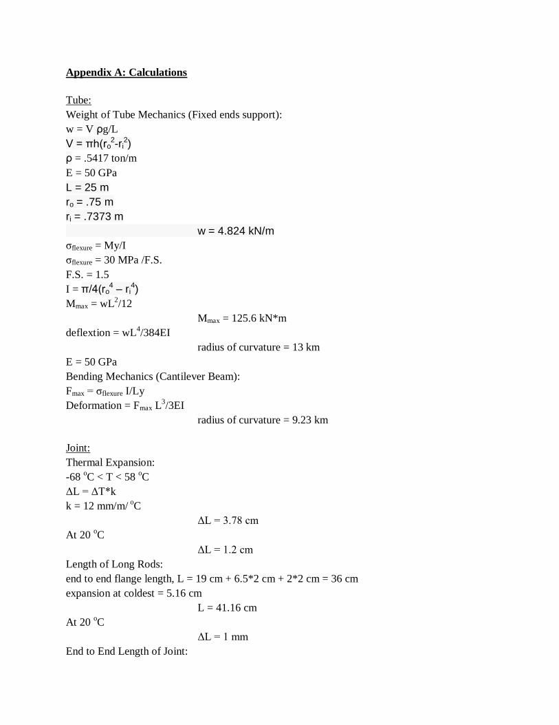
Appendix A: Calculations
Tube:
Weight of Tube Mechanics (Fixed ends support):
w = V ρg/L
V = πh(ro2-ri
2)
ρ = .5417 ton/m
E = 50 GPa
L = 25 m
ro = .75 m
ri = .7373 m
w = 4.824 kN/m
σflexure = My/I
σflexure = 30 MPa /F.S.
F.S. = 1.5
I = π/4(ro4 – ri
4)
Mmax = wL2/12
Mmax = 125.6 kN*m
deflextion = wL4/384EI
radius of curvature = 13 km
E = 50 GPa
Bending Mechanics (Cantilever Beam):
Fmax = σflexure I/Ly
Deformation = Fmax L3/3EI
radius of curvature = 9.23 km
Joint:
Thermal Expansion:
-68 oC < T < 58
oC
ΔL = ΔT*k
k = 12 mm/m/ o
C
ΔL = 3.78 cm
At 20 oC
ΔL = 1.2 cm
Length of Long Rods:
end to end flange length, L = 19 cm + 6.5*2 cm + 2*2 cm = 36 cm
expansion at coldest = 5.16 cm
L = 41.16 cm
At 20 oC
ΔL = 1 mm
End to End Length of Joint:
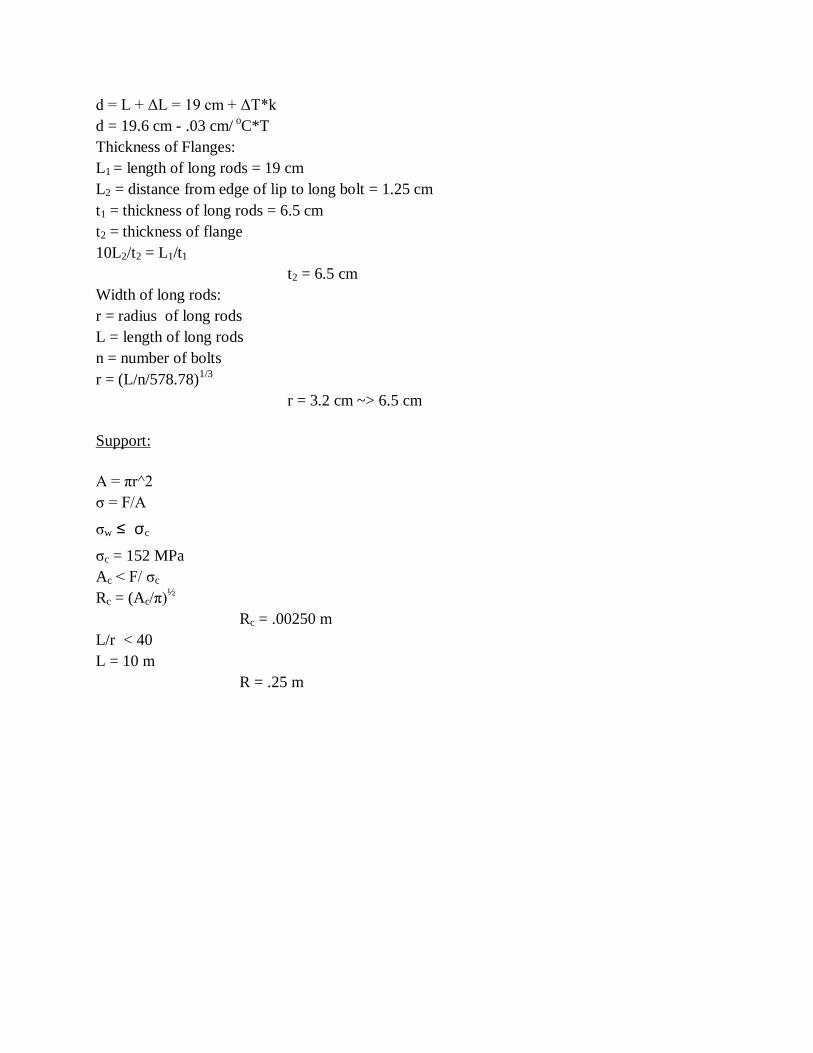
d = L + ΔL = 19 cm + ΔT*k
d = 19.6 cm - .03 cm/ oC*T
Thickness of Flanges:
L1 = length of long rods = 19 cm
L2 = distance from edge of lip to long bolt = 1.25 cm
t1 = thickness of long rods = 6.5 cm
t2 = thickness of flange
10L2/t2 = L1/t1
t2 = 6.5 cm
Width of long rods:
r = radius of long rods
L = length of long rods
n = number of bolts
r = (L/n/578.78)1/3
r = 3.2 cm ~> 6.5 cm
Support:
A = πr^2
σ = F/A
σw ≤ σc
σc = 152 MPa
Ac < F/ σc
Rc = (Ac/π)½
Rc = .00250 m
L/r < 40
L = 10 m
R = .25 m

Tube Overall Design
Tube lip has
a slightly
bigger
diameter
Figure D1: Tube Overall Design
DAEVIN DEV
Lip End Cross
Section
Isometric
View
Isometric View Zoomed
In
Tube Middle Cross-
Section
Tube Side
View
Lip End Cross
Section

Combined Tube Alignment
Figure D2: Combined Tube Alignment
DAEVIN DEV
Combined Tube Top View Cross-
Section
Tube
1 Tube 2
Rubber Joint
Seal
Ductal® concrete rods
that bypass rubber
seals

Proper Concrete Pipe Handling
Figure D4: Concrete Pipe Handling
DAEVIN DEV

Removing & Replacing Tubes
Figure D3: Removing & Replacing Tubes
DAEVIN DEV