etag 001 metal anchors for use in concrete · 90693.97 etag 001 edition 1997 guideline for european...
TRANSCRIPT

90693.97
ETAG 001Edition 1997
GUIDELINE FOR EUROPEAN TECHNICAL APPROVALOF
METAL ANCHORSFOR USE IN CONCRETE
Annex C: DESIGN METHODS FOR ANCHORAGESAmended October 2001
EOTA Avenue des Arts 40 Kunstlaan, 1040 Brussels
European Organisation for Technical ApprovalsEuropäische Organisation für Technische ZulassungenOrganisation Européenne pour l’Agrément Technique

- 2 -
90693.97
TABLE OF CONTENTSANNEX C
Design methods for anchoragesIntroduction
1 Scope1.1 Type of anchors, anchor groups and number of anchors1.2 Concrete member1.3 Type and direction of load1.4 Safety class
2 Terminology and Symbols2.1 Indices2.2 Actions and resistances2.3 Concrete and steel2.4 Characteristic values of anchors
3 Design and safety concept3.1 General3.2 Ultimate limit state3.2.1 Partial safety factors for actions3.2.2 Design resistance3.2.3 Partial safety factors for resistances3.2.3.1 Concrete cone failure, splitting failure and pull-out failure3.2.3.2 Steel failure3.3 Serviceability limit state
4 Static analysis4.1 Non-cracked and cracked concrete4.2 Loads acting on anchors4.2.1 Tension loads4.2.2 Shear loads4.2.2.1 Distribution of shear loads4.2.2.2 Shear loads without lever arm4.2.2.3 Shear loads with lever arm
5 Ultimate limit state5.1 General5.2 Design method A5.2.1 General5.2.2 Resistance to tension loads5.2.2.1 Required proofs5.2.2.2 Steel failure5.2.2.3 Pull-out failure5.2.2.4 Concrete cone failure5.2.2.5 Splitting failure due to anchor installation5.2.2.6 Splitting failure due to loading5.2.3 Resistance to shear loads5.2.3.1 Required proofs5.2.3.2 Steel failure5.2.3.3 Concrete pryout failure5.2.3.4 Concrete edge failure5.2.4 Resistance to combined tension and shear loads5.3 Design method B5.4 Design method C
6 Serviceability limit state6.1 Displacements6.2 Shear load with changing sign
7 Additional proofs for ensuring the characteristic resistance of concrete member7.1 General7.2 Shear resistance of concrete member
- 3 -
90693.97
7.3 Resistance to splitting forces

- 4 -
90693.97
Introduction
The design methods for anchorages are intended to be used for the design of anchorages under dueconsideration of the safety and design concept within the scope of the European Technical Approvals (ETA) ofanchors.
The design methods given in Annex C are based on the assumption that the required tests for assessing theadmissible service conditions given in Part 1 and the subsequent Parts have been carried out. Therefore AnnexC is a pre-condition for assessing and judging of anchors. The use of other design methods will requirereconsideration of the necessary tests.
The ETA’s for anchors give the characteristic values only of the different approved anchors. The design of theanchorages (e.g. arrangement of anchors in a group of anchors, effect of edges or corners of the concretemember on the characteristic resistance) shall be carried out according to the design methods described inChapter 3 to 5 taking account of the corresponding characteristic values of the anchors.
Chapter 7 gives additional proofs for ensuring the characteristic resistance of the concrete member which arevalid for all anchor systems.
The design methods are valid for all anchor types. However, the equations given in the following are valid foranchors according to current experience only (see Annex B). If values for the characteristic resistance, spacings,edge distances and partial safety factors differ between the design methods and the ETA, the value given in theETA governs. In the absence of national regulations the partial safety factors given in the following may be used.

- 5 -
90693.97
1 Scope
1.1 Type of anchors, anchor groups and number of anchors
The design methods apply to the design of anchorages in concrete using approved anchors which fulfill therequirements of this Guideline. The characteristic values of these anchors are given in the relevant ETA.
The design methods are valid for single anchors and anchor groups. In case of an anchor group the loads areapplied to the individual anchors of the group by means of a rigid fixture. In an anchor group only anchors of thesame type, size and length shall be used.
The design methods cover single anchors and anchor groups according to Figure 1.1 and 1.2. Other anchorarrangements e.g. in a triangular or circular pattern are also allowed; however, the provisions of this designmethod should be applied with engineering judgement. Figure 1.1 is only valid if the edge distance in alldirections is greater than or equal to 10 hef.
Figure 1.1 Anchorages situated far from edges (c > 10 hef) covered by the design methods
Figure 1.2 Anchorages situated near to an edge (c < 10 hef) covered by the design methods
1.2 Concrete member
The concrete member shall be of normal weight concrete of at least strength class C 20/25 and at most strengthclass C 50/60 to ENV 206 [8] and shall be subjected only to predominantly static loads. The concrete may becracked or non-cracked (see 4.1).
1.3 Type and direction of load
The design methods apply to anchors subjected to static or quasi-static loadings and not to anchors subjected toimpact or seismic loadings or loaded in compression.
1.4 Safety class
Anchorages carried out in accordance with these design methods are considered to belong to anchorages, thefailure of which would cause risk to human life and/or considerable economic consequences.
- 6 -
90693.97
2 Terminology and Symbols
The notations and symbols frequently used in the design methods are given below. Further notations are givenin the text.
2.1 Indices
S = actionR = resistanceM = materialk = characteristic valued = design values = steelc = concretecp = concrete pryoutp = pull-outsp = splittingu = ultimatey = yield
2.2 Actions and resistances
F = force in general (resulting force)N = normal force (positiv: tension force, negativ: compression force)V = shear forceM = moment
FSk (NSk ; VSk ; MSk ; MT,Sk) = characteristic value of actions acting on a single anchor or the fixtureof an anchor group respectively (normal load, shear load, bendingmoment, torsion moment)
FSd (NSd ; VSd ; MSd , MT,Sd) = design value of actions acting on a single anchor or the fixture of ananchor group respectively (normal load, shear load, bending moment,torsion moment)
NSdh ( VSd
h ) = design value of tensile load (shear load) acting on the most stressedanchor of an anchor group calculated according to 4.2
NSdg ( VSd
g ) = design value of the sum (resultant) of the tensile (shear) loads actingon the tensioned (sheared) anchors of a group calculated accordingto 4.2
FRk (NRk ; VRk) = characteristic value of resistance of a single anchor or an anchorgroup respectively (normal force, shear force)
FRd (NRd ; VRd) = design value of resistance of a single anchor or an anchor grouprespectively (normal force, shear force)
2.3 Concrete and steel
fck,cube = characteristic concrete compression strength measured on cubes with a side length of 150 mm(value of concrete strength class according to ENV 206 [8])
fyk = characteristic steel yield strength (nominal value)fuk = characteristic steel ultimate tensile strength (nominal value)As = stressed cross section of steel
Wel = elastic section modulus calculated from the stressed cross section of steel (πd3
32 for a round
section with diameter d)
- 7 -
90693.97
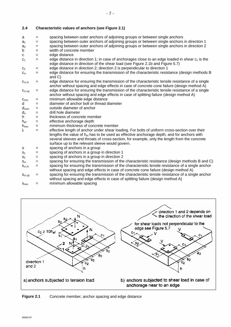
2.4 Characteristic values of anchors (see Figure 2.1)
a = spacing between outer anchors of adjoining groups or between single anchorsa1 = spacing between outer anchors of adjoining groups or between single anchors in direction 1a2 = spacing between outer anchors of adjoining groups or between single anchors in direction 2b = width of concrete memberc = edge distancec1 = edge distance in direction 1; in case of anchorages close to an edge loaded in shear c1 is the
edge distance in direction of the shear load (see Figure 2.1b and Figure 5.7)c2 = edge distance in direction 2; direction 2 is perpendicular to direction 1ccr = edge distance for ensuring the transmission of the characteristic resistance (design methods B
and C)ccr,N = edge distance for ensuring the transmission of the characteristic tensile resistance of a single
anchor without spacing and edge effects in case of concrete cone failure (design method A)ccr,sp = edge distance for ensuring the transmission of the characteristic tensile resistance of a single
anchor without spacing and edge effects in case of splitting failure (design method A)cmin = minimum allowable edge distanced = diameter of anchor bolt or thread diameterdnom = outside diameter of anchordo = drill hole diameterh = thickness of concrete memberhef = effective anchorage depthhmin = minimum thickness of concrete memberlf = effective length of anchor under shear loading. For bolts of uniform cross-section over their
lengths the value of hef has to be used as effective anchorage depth, and for anchors withseveral sleeves and throats of cross-section, for example, only the length from the concretesurface up to the relevant sleeve would govern.
s = spacing of anchors in a groups1 = spacing of anchors in a group in direction 1s2 = spacing of anchors in a group in direction 2scr = spacing for ensuring the transmission of the characteristic resistance (design methods B and C)scr,N = spacing for ensuring the transmission of the characteristic tensile resistance of a single anchor
without spacing and edge effects in case of concrete cone failure (design method A)scr,sp = spacing for ensuring the transmission of the characteristic tensile resistance of a single anchor
without spacing and edge effects in case of splitting failure (design method A)smin = minimum allowable spacing
Figure 2.1 Concrete member, anchor spacing and edge distance
- 8 -
90693.97
3 Design and safety concept
3.1 General
For the design of anchorages the safety concept of partial safety factors shall be applied. It shall be shown thatthe value of the design actions Sd does not exceed the value of the design resistance Rd.
Sd < Rd (3.1)
Sd = value of design actionRd = value of design resistance
In the absence of national regulations the design actions in the ultimate limit state or serviceability limit staterespectively shall be calculated according to Eurocode 2 [1] or Eurocode 3 [14].
In the simplest case (permanent load and one variable load acting in one direction) the followingequation applies:
Sd = γG . Gk + γQ . Qk (3.2)
Gk (Qk) = characteristic value of a permanent (variable) actionγG (γQ) = partial safety factor for permanent (variable) action
The design resistance is calculated as follows:
Rd = Rk/γM (3.3)
Rk = characteristic resistance of a single anchor or an anchor groupγM = partial safety factor for material
3.2 Ultimate limit state
3.2.1 Partial safety factors for actions
The partial safety factors for actions depend on the type of loading and shall be taken from national regulationsor, in the absence of them, from [1] or [14]. In Equation (3.2) the partial safety factor according to [1] is γG = 1.35for permanent actions and γQ = 1.5 for variable actions.
3.2.2 Design resistance
The design resistance is calculated according to Equation (3.3). In design method A the characteristic resistanceis calculated for all load directions and failure modes.In design methods B und C only one characteristic resistance is given for all load directions and failure modes.
3.2.3 Partial safety factors for resistances
In the absence of national regulations the following partial safety factors may be used. However, the value of γ2may not be changed because it describes a characteristic of the anchors.
3.2.3.1 Concrete cone failure, splitting failure and pull-out failure
The partial safety factors for concrete cone failure (γMc), splitting failure (γMsp) and pull-out failure (γMp) are givenin the relevant ETA.
They are valid only if after installation the actual dimensions of the effective anchorage depth, spacing and edgedistance are not less than the design values (only positive tolerances allowed).
For anchors to according current experience the partial safety factor γMc is determined from:γMc = γc . γ1 . γ2γc = partial safety factor for concrete under compression = 1.5γ1 = partial safety factor taking account of the scatter of the tensile strength of site concrete
= 1.2 for concrete produced and cured with normal careγ2 = partial safety factor taking account of the installation safety of an anchor system
The partial safety factor γ2 is evaluated from the results of the installation safety tests,see Part 1, 6.1.2.2.2.
- 9 -
90693.97
Tension loadingγ2 = 1.0 for systems with high installation safety
= 1.2 for systems with normal installation safety= 1.4 for systems with low but still acceptable installation safety
Shear loadingγ2 = 1.0
For the partial safety factors γMsp and γMp the value for γ Mc may be taken.
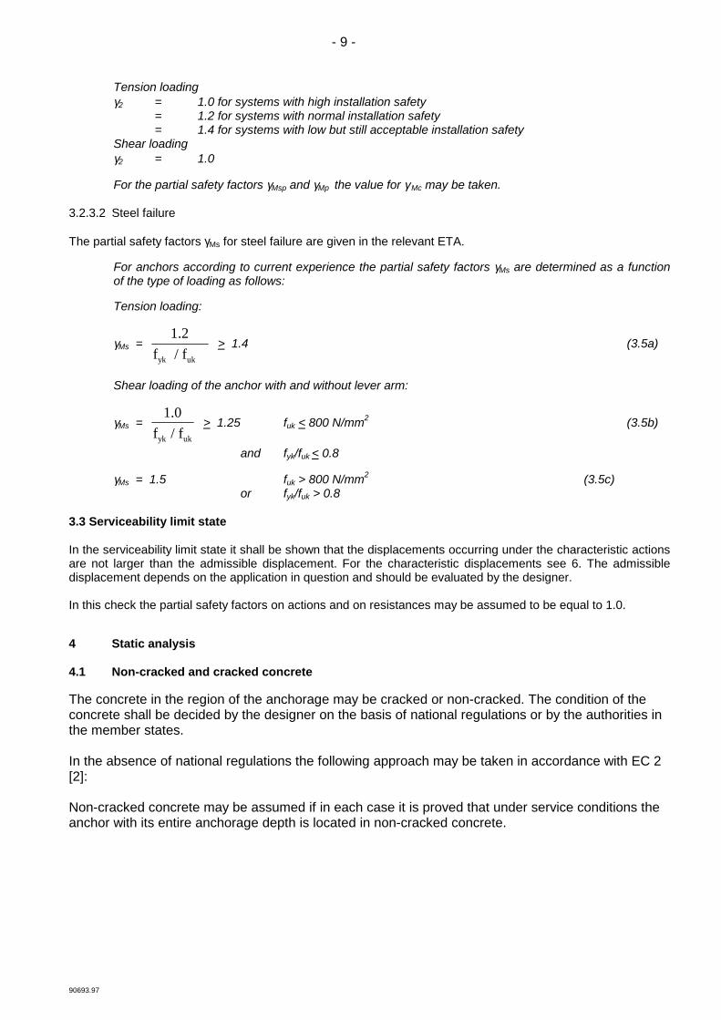
3.2.3.2 Steel failure
The partial safety factors γMs for steel failure are given in the relevant ETA.
For anchors according to current experience the partial safety factors γMs are determined as a functionof the type of loading as follows:
Tension loading:
γMs = 1.2
f / f yk uk
> 1.4 (3.5a)
Shear loading of the anchor with and without lever arm:
γMs = 1.0
f / fyk uk
> 1.25 fuk < 800 N/mm2 (3.5b)
and fyk/fuk < 0.8
γMs = 1.5 fuk > 800 N/mm2 (3.5c)or fyk/fuk > 0.8
3.3 Serviceability limit state
In the serviceability limit state it shall be shown that the displacements occurring under the characteristic actionsare not larger than the admissible displacement. For the characteristic displacements see 6. The admissibledisplacement depends on the application in question and should be evaluated by the designer.
In this check the partial safety factors on actions and on resistances may be assumed to be equal to 1.0.
4 Static analysis
4.1 Non-cracked and cracked concrete
The concrete in the region of the anchorage may be cracked or non-cracked. The condition of theconcrete shall be decided by the designer on the basis of national regulations or by the authorities inthe member states.
In the absence of national regulations the following approach may be taken in accordance with EC 2[2]:
Non-cracked concrete may be assumed if in each case it is proved that under service conditions theanchor with its entire anchorage depth is located in non-cracked concrete.
- 10 -
90693.97
This proof can be taken as fulfilled if Equation (4.1) is observed:
σL + σR < 0* (4.1)
σL = stresses in the concrete induced by external loads, including anchors loadsσR = stresses in the concrete due to restraint of intrinsic imposed deformations
(e.g. shrinkage of concrete) or extrinsic imposed deformations (e.g. due todisplacement of support or temperature variations). If no detailed analysis isconducted, then σR = 3 N/mm2 should be assumed, according to EC 2 [1].
The stresses σL and σR shall be calculated assuming that the concrete is non-cracked (state I). Forplane concrete members which transmit loads in two directions (e.g. slabs, walls) Equation (4.1) shallbe fulfilled for both directions.
4.2 Loads acting on anchors
In the static analysis the loads and moments are given which are acting on the fixture. To design the anchoragethe loads acting on each anchor shall be calculated, taking into account partial safety factors for actionsaccording to 3.2.1 in the ultimate limit state and according to 3.3 in the serviceability limit state.
With single anchors normally the loads acting on the anchor are equal to the loads acting on the fixture. Withanchor groups the loads, bending and torsion moments acting on the fixture shall be distributed to tension andshear forces acting on the individual anchors of the group. This distribution shall be calculated according to thetheory of elasticity.
4.2.1 Tension loads
In general, the tension loads acting on each anchor due to loads and bending moments acting on the fixtureshall be calculated according to the theory of elasticity using the following assumptions:
a) The anchor plate does not deform under the design actions. To ensure the validity of this assumption theanchor plate shall be sufficiently stiff and its design should be carried out according to standards for steelstructures ensuring elastic behaviour.
b) The stiffness of all anchors is equal and corresponds to the modulus of elasticity of the steel. The modulus ofelasticity of concrete is given in [1]. As a simplification it may be taken as Ec = 30 000 N/mm2.
c) In the zone of compression under the fixture the anchors do not contribute to the transmission of normalforces (see Figure 4.1b).
If in special cases the anchor plate is not sufficiently stiff, then the flexibility of the anchor plate should be takeninto account when calculating loads acting on the anchors.
In the case of anchor groups with different levels of tension forces Nsi acting on the individual anchors of a groupthe eccentricity eN of the tension force NS
g of the group may be calculated (see Figure 4.1), to enable a moreaccurate assessment of the anchor group resistance.
__________________
* The authorities in the member states may adjust the numerical value to their specificconditions

- 11 -
90693.97
Figure 4.1 Example of anchorages subjected to an eccentric tensile load N gS
If the tensioned anchors do not form a rectangular pattern, for reasons of simplicity the group of tensionedanchors may be resolved into a group rectangular in shape (that means the centre of gravity of the tensionedanchors may be assumed in the center of the axis in Figure 4.1c).

- 12 -
90693.97
4.2.2 Shear loads
4.2.2.1 Distribution of loads
For the distribution of shear loads and torsion moments acting on the fixture to the anchors of a group thefollowing cases shall be distinguished:
a) All anchors take up shear loads if the hole clearance is not greater than given in Table 4.1 and the edgedistance is larger than 10 hef (see Figure 4.2 a-c).
Figure 4.2 Examples of load distribution, when all anchors take up shear loads
b) Only the most unfavourable anchors take up shear loads if the edge distance is smaller than 10 hef(independent of the hole clearance) (see Figure 4.3 a-c) or the hole clearance is larger than the valuesgiven in Table 4.1 (independent of the edge distance) (see Figure 4.4 a and b).
Figure 4.3 Examples of load distribution for anchorages close to an edge
- 13 -
90693.97
Figure 4.4 Examples of load distribution if the hole clearance is larger than the value according toTable 4.1
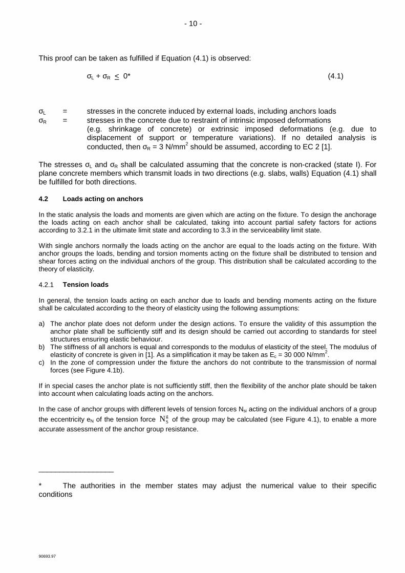
c) Slotted holes in direction of the shear load prevent anchors to take up shear loads. This canbe favourable in case of anchorages close to an edge (see Figure 4.5).
Figure 4.5 Examples of load distribution for an anchorage with slotted holes
Table 4.1 Diameter of clearance hole in the fixture
external diameterd1) or dnom
2) (mm)6 8 10 12 14 16 18 20 22 24 27 30
diameter df of clearancehole in the fixture (mm)
7 9 12 14 16 18 20 22 24 26 30 33
1) if bolt bears against the fixture2) if sleeve bears against the fixture
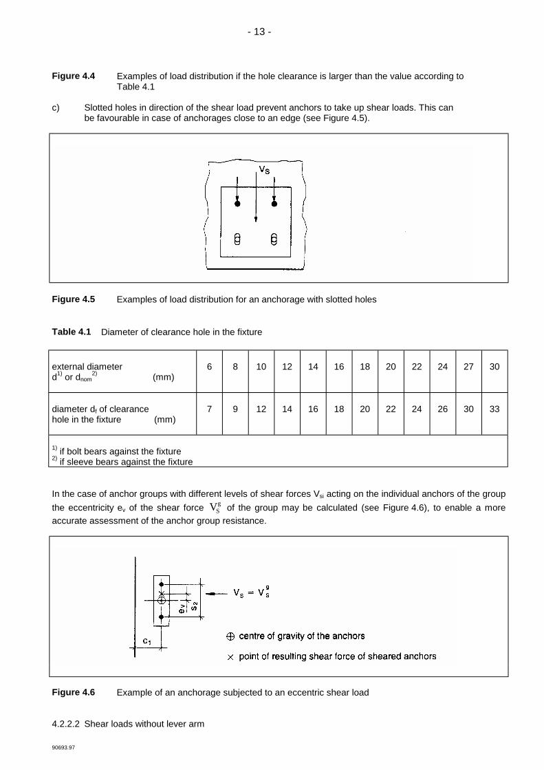
In the case of anchor groups with different levels of shear forces Vsi acting on the individual anchors of the groupthe eccentricity ev of the shear force VS
g of the group may be calculated (see Figure 4.6), to enable a moreaccurate assessment of the anchor group resistance.
Figure 4.6 Example of an anchorage subjected to an eccentric shear load
4.2.2.2 Shear loads without lever arm
- 14 -
90693.97
Shear loads acting on anchors may be assumed to act without lever arm if both of the following conditions arefulfilled:
a) The fixture shall be made of metal and in the area of the anchorage be fixed directly to the concrete eitherwithout an intermediate layer or with a levelling layer of mortar with a thickness < 3 mm.
b) The fixture shall be in contact with the anchor over its entire thickness.
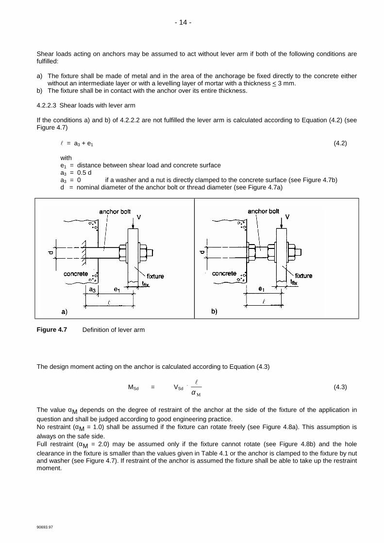
4.2.2.3 Shear loads with lever arm
If the conditions a) and b) of 4.2.2.2 are not fulfilled the lever arm is calculated according to Equation (4.2) (seeFigure 4.7)
! = a3 + e1 (4.2)
withe1 = distance between shear load and concrete surfacea3 = 0.5 da3 = 0 if a washer and a nut is directly clamped to the concrete surface (see Figure 4.7b)d = nominal diameter of the anchor bolt or thread diameter (see Figure 4.7a)
Figure 4.7 Definition of lever arm
The design moment acting on the anchor is calculated according to Equation (4.3)
MSd = VSd . !
α M(4.3)
The value αM depends on the degree of restraint of the anchor at the side of the fixture of the application inquestion and shall be judged according to good engineering practice.No restraint (αM = 1.0) shall be assumed if the fixture can rotate freely (see Figure 4.8a). This assumption isalways on the safe side.Full restraint (αM = 2.0) may be assumed only if the fixture cannot rotate (see Figure 4.8b) and the holeclearance in the fixture is smaller than the values given in Table 4.1 or the anchor is clamped to the fixture by nutand washer (see Figure 4.7). If restraint of the anchor is assumed the fixture shall be able to take up the restraintmoment.

- 15 -
90693.97
Figure 4.8 Fixture without (a) and with (b) restraint

- 16 -
90693.97
5 Ultimate limit state
5.1 General
For the design of anchorages in the ultimate limit state, there are three different design methods available. Thelinkage of the design methods and the required tests for admissible service conditions is given in Table 5.1. In5.2 the general design method A is described; in 5.3 and 5.4 the simplified methods B and C are treated. Thedesign method to be applied is given in the relevant ETA.
According to Equation (3.1) it shall be shown that the design value of the action is equal to or smaller than thedesign value of the resistance. The characteristic values of the anchor to be used for the calculation of theresistance in the ultimate limit state are given in the relevant ETA.
Spacing, edge distance as well as thickness of concrete member shall not remain under the given minimumvalues.
The spacing between outer anchor of adjoining groups or the distance to single anchors shall be a > scr,N (designmethod A) or scr respectively (design method B and C).
Table 5.1 Linkage of the design methods and the required tests for admissible service conditions
Designmethod
cracked andnon-cracked
concrete
non-crackedconcrete
only
characteristic resistance for C 20/25 C 20/25 to only C 50/60
tests accordingAnnex BOption
Axx
xx
x
x
x
x
1278
Bxx
xx
x
x
x
x
34910
Cxx
xx
x
x
x
x
561112
5.2 Design method A
5.2.1 General
In design method A it shall be shown that Equation (3.1) is observed for all loading directions (tension, shear) aswell as all failure modes (steel failure, pull-out failure and concrete failure).
In case of a combined tension and shear loading (oblique loading) the condition of interaction according to 5.2.4shall be observed.
For Options 2 and 8 (see Part 1, Table 5.3), fck,cube = 25 N/mm2 shall be inserted in Equations (5.2a) and (5.7a).

- 17 -
90693.97
5.2.2 Resistance to tension loads
5.2.2.1 Required proofs
single anchor anchor group
steel failure NSd < NRk,s / γMs N Sdh < NRk,s / γMs
pull-out failure NSd < NRk,p / γMp N Sdh < NRk,p / γMp
concrete cone failure NSd < NRk,c / γMc N Sdg < NRk,c / γMc
splitting failure NSd < NRk,sp / γMsp N Sdg
< NRk,sp / γMsp
5.2.2.2 Steel failure
The characteristic resistance of an anchor in case of steel failure, NRk,s, is given in the relevant ETA.
The value of NRk,s is obtained from Equation (5.1)
NRk,s = As . fuk [N] (5.1)
5.2.2.3 Pull-out failure
The characteristic resistance in case of failure by pull-out, NRk,p, shall be taken from the relevant ETA.
5.2.2.4 Concrete cone failure
The characteristic resistance of an anchor or a group of anchors, respectively, in case of concrete cone failureis:
NRk,c = N Rk,c0 .
AA
c,N
c,N0 .ψs,N . ψre,N . ψec,N . ψucr,N [N] (5.2)
The different factors of Equation (5.2) for anchors according to current experience are given below:
a) The initial value of the characteristic resistance of an anchor placed in cracked concrete is obtained by:
NRk,c0 = 7.2 ⋅ fck,cube . hef
1.5 [N] (5.2a)
fck,cube [N/mm2]; hef [mm]
b) The geometric effect of spacing and edge distance on the characteristic resistance is taken into accountby the value Ac,N/ Ac,N
0 , where:
Ac,N0 = area of concrete of an individual anchor with large spacing and edge distance at the
concrete surface, idealizing the concrete cone as a pyramid with a height equal to hefand a base length equal to scr,N (see Figure 5.1).
= scr,N ⋅ scr,N (5.2b)
Ac,N = actual area of concrete cone of the anchorage at the concrete surface. It is limited byoverlapping concrete cones of adjoining anchors (s < scr,N) as well as by edges of theconcrete member (c < ccr,N). Examples for the calculation of Ac,N are given in Figure 5.2.

- 18 -
90693.97
Figure 5.1 Idealized concrete cone and area A0c ,
N of concrete cone of an individual anchor

- 19 -
90693.97
Figure 5.2 Examples of actual areas Ac,N of the idealized concrete cones for different arrangements ofanchors in the case of axial tension load
c) The factor ψs,N takes account of the disturbance of the distribution of stresses in the concretedue to edges of the concrete member. For anchorages with several edge distances (e.g.anchorage in a corner of the concrete member or in a narrow member), the smallest edgedistance, c, shall be inserted in Equation (5.2c).
ψs,N = 0.7 + 0.3 . c
ccr,N
< 1 (5.2c)
a) individual anchor at the edge of concrete member
b) group of two anchors at the edge of concrete member
c) group of four anchors at a corner of concrete member

- 20 -
90693.97
d) The shell spalling factor, ψre,N, takes account of the effect of a reinforcement
ψre,N = 0.5 + h200
ef < 1 (5.2d)
hef [mm]
If in the area of the anchorage there is a reinforcement with a spacing > 150 mm (any diameter) or witha diameter < 10 mm and a spacing > 100 mm then a shell spalling factor of ψre,N = 1.0 may be appliedindependently of the anchorage depth.
e) The factor of ψec,N takes account of a group effect when different tension loads are actingon the individual anchors of a group.
ψec,N = 1
1 2e / sN cr,N+ < 1 (5.2e)
eN = eccentricity of the resulting tensile load acting on the tensioned anchors (see 4.2.1).Where there is an eccentricity in two directions, ψec,N shall be determined separately foreach direction and the product of both factors shall be inserted in Equation (5.2).
As a simplification factor ψec,N = 1.0 may be assumed, if the most stressed anchor is checked accordingto Equation (3.1) ( NSd
h < NRk,ch / γMc) and the resistance of this anchor is taken as
NRk,ch = NRk,c / n (5.2f)
with n = number of tensioned anchors
f) The factor of ψucr,N takes account of the position of the anchorage in cracked or non-crackedconcrete
ψucr,N = 1.0 for anchorages in cracked concrete (5.2g1)= 1.4 for anchorages in non-cracked concrete (5.2g2)
The factor ψucr,N = 1.4 may be used only if in each individual case it is proven - as described in 4.1 - thatthe concrete in which the anchor is placed is non-cracked.
g) The values scr,N and ccr,N are given in the relevant ETA
For anchor according to current experience scr,N = 2 ccr,N = 3 hef is taken
Special casesFor anchorages with three or more edges with an edge distance cmax < ccr,N (cmax = largest edgedistance) (see Figure 5.3) the calculation according to Equation 5.2 leads to results which are on thesafe side.
More precise results are obtained if for hef the value
hef' =
cccr N
max
,
. hef

- 21 -
90693.97
is inserted in Equation (5.2a) and for the determination of Ac,N0 and Ac,N according to Figures 5.1 and
5.2 as well as in Equations (5.2b), (5.2c) and (5.2e) the values
scr,N' =
cc
max
cr,N
. scr,N
ccr,N' = cmax
are inserted for scr,N or ccr,N, respectively.
Figure 5.3 Examples of anchorages in concrete members where hef , scr,N and ccr,N may be used
5.2.2.5 Splitting failure due to anchor installation
Splitting failure is avoided during anchor installation by complying with minimum values for edge distance cmin,spacing smin, member thickness hmin and reinforcement as given in the relevant ETA.
5.2.2.6 Splitting failure due to loading
a) It may be assumed that splitting failure will not occur, if the edge distance in all directions isc > 1.5 ccr,sp and the member depth is h > 2 hef.
b) With anchors suitable for use in cracked concrete, the calculation of the characteristic splittingresistance may be ommitted if the following two conditions are fulfilled:
− a reinforcement is present which limits the crack width to wk ∼ 0.3 mm, taking into accountthe splitting forces according to 7.3
− the characteristic resistance for concrete cone failure and pull-out failure is calculated forcracked concrete.
If the conditions a) or b) are not fulfilled, then the characteristic resistance of a single anchor or an anchor groupin case of splitting failure should be calculated according to Equation (5.3).
NRk,sp = NRk,c0 .
AA
c N
c N
,
,0 . ψs,N . ψre,N . ψec,N . ψucr,N . ψh,sp [N] (5.3)
with NRk,c0 , ψs,N, ψre,N, ψec,N, ψucr,N according to Equations (5.2a) to (5.2g) and Ac,N., Ac N,
0 as defined in5.2.2.4 b), however the values ccr,N and scr,N should be replaced by ccr,sp and scr,sp.
ψh,sp = factor to account for the influence of the actual member depth, h, on the splitting resistance foranchors according to current experience

- 22 -
90693.97
= hhef2
2 3/
< 1.5 (5.3a)
If the edge distance of an anchor is smaller than the value ccr,sp then a longitudinal reinforcement should beprovided along the edge of the member.
5.2.3 Resistance to shear loads
5.2.3.1 Required proofs
single anchor anchor group
steel failure, shear loadwithout lever arm
VSd < VRk,s / γMs V Sdh < VRk,s / γMs
steel failure, shear loadwith lever arm
VSd < VRk,s / γMs V Sdh < VRk,s / γMs
concrete pryout failure VSd < NRk,cp / γMc V Sdg < NRk,cp / γMc
concrete edge failure VSd < NRk,c / γMc V Sdg
< VRk,c / γMc
5.2.3.2 Steel failure
a) Shear load without lever arm
The characteristic resistance of an anchor in case of steel failure, VRk,s shall be taken from the relevantETA.
The value VRk,s for anchors according to current experience is obtained from Equation (5.4)
VRk,s = 0.5 ·As · fuk [N] (5.4)
Equation (5.4) is not valid for anchors with a significantly reduced section along the length of thebolt (e.g. in case of bolt type expansion anchors).
In case of anchor groups, the characteristic shear resistance given in the relevant ETA shall bemultiplied with a factor 0.8, if the anchor is made of steel with a rather low ductility (rupture elongation A5< 8%)
b) Shear load with lever arm
The characteristic resistance of an anchor, VRk,s, is given by Equation (5.5).
VRk,s = α M Rk,sM⋅
![N] (5.5)
where αM = see 4.2.2.3
! = lever arm according to Equation (4.2)MRk,s = MRk,s
0 (1 - NSd/NRd,s) [Nm] (5.5a)NRd,s = NRk,s / γMsNRk,s , γMs to be taken from the relevant ETAMRk,s
0 = characteristic bending resistance of an individual anchor
The characteristic bending resistance MRk,s0 shall be taken from the relevant ETA.

- 23 -
90693.97
The value of MRk,s0 for anchors according to current experience is obtained from Equation (5.5b).
MRk,s0 = 1.2 ·Wel · fuk [Nm] (5.5b)
Equation (5.5b) may be used only, if the anchor has not a significantly reduced section along the lengthof the bolt.
5.2.3.3 Concrete pryout failure
Anchorages with short stiff anchors can fail by a concrete pryout failure at the side opposite to load direction (seeFigure 5.4). The corresponding characteristic resistance VRk,cp may be calculated from Equation (5.6).
VRk,cp = k . NRk,c (5.6)
where k = factor to be taken from the relevant ETANRk,c according to 5.2.2.4 determined for the anchors loaded in shear.
For anchors according to current experience failing under tension load by concrete cone failure thefollowing values are on the safe side
k = 1 hef < 60mm (5.6a)k = 2 hef > 60mm (5.6b)
Figure 5.4 Concrete pryout failure on the side opposite to load direction
5.2.3.4 Concrete edge failure
For anchorages shown in Figure 1.1 with an edge distance in all directions c > 10 hef, a check of thecharacteristic concrete edge failure resistance may be omitted.
The characteristic resistance for an anchor or an anchor group in the case of concrete cone failure at edgescorresponds to:
VRk,c = VRk,c0 .
AA
c V
c V
,
,0 . ψs,V . ψh,V . ψα,V . ψec,V . ψucr,V [N] (5.7)
The different factors of Equation (5.7) for anchors according to current experience are given below:

- 24 -
90693.97
a) The initial value of the characteristic resistance of an anchor placed in cracked concrete and loadedperpendicular to the edge corresponds to:
VRk,c0 = 0.45 ⋅ dnom ⋅ (lf/dnom)0.2 ⋅ fck,cube ⋅ c1
1.5 [N] (5.7a)
dnom, lf, c1 [mm]; fck,cube [N/mm2]
b) The geometrical effect of spacing as well as of further edge distances and the effect of thickness of theconcrete member on the characteristic load is taken into account by the ratio Ac,V/ Ac,V
0 .
where:
Ac,V0 = area of concrete cone of an individual anchor at the lateral concrete surface not affected by
edges parallel to the assumed loading direction, member thickness or adjacent anchors,assuming the shape of the fracture area as a half pyramid with a height equal to c1 and abase-length of 1.5 c1 and 3 c1 (Figure 5.5).
= 4,5 c12 (5.7b)
Ac,V = actual area of concrete cone of anchorage at the lateral concrete surface. It is limited by theoverlapping concrete cones of adjoining anchors (s < 3 c1) as well as by edges parallel to theassumed loading direction (c2 < 1.5 c1) and by member thickness (h < 1.5 c1). Examples forcalculation of Ac,V are given in Figure 5.6.
For the calculation of Ac,V0 and Ac,V it is assumed that the shear loads are applied perpendicular to the edge of
the concrete member.For anchorages placed at a corner, the resistances for both edges shall be calculated and the smallest value isdecisive (see Figure 5.7).
Figure 5.5 Idealized concrete cone and area A0c,V of concrete cone for a single anchor

- 25 -
90693.97
Figure 5.6 Examples of actual areas of the idealized concrete cones for different anchor arrangementsunder shear loading

- 26 -
90693.97
Figure 5.7 Example of an anchor group at a corner under shear loading, where resistances shall becalculated for both edges
c) The factor ψs,V takes account of the disturbance of the distribution of stresses in the concretedue to further edges of the concrete member on the shear resistance. For anchorages with two edgesparallel to the assumed direction of loading (e.g. in a narrow concrete member) the smaller edgedistance shall be inserted in Equation (5.7c).
ψs,V = 0.7 + 0.3 . c
1.5 c2
1
< 1 (5.7c)
d) The factor ψh,V takes account of the fact that the shear resistance does not decrease proportionally tothe member thickness as assumed by the ratio Ac,V/ Ac,V
0 .
ψh,V = (15 1. c
h)1/3 > 1 (5.7d)
e) The factor ψαV takes account of the angle αV between the load applied, VSd, and the directionperpendicular to the free edge of the concrete member (see Figure 5.8).
ψα,V = 1.0 for 0° < αV < 55° area 1
ψα,V = 1
0 5cos . sinα α+ ⋅ V
for 55°< αV > 90° area 2 (5.7e)
ψα,V = 2.0 for 90°< αV < 180° area 3
- 27 -
90693.97
Figure 5.8 Definition of angle αV
f) The factor ψec,V takes account of a group effect when different shear loads are acting on the individualanchors of a group.
ψec,V = 1
1 2 3 1+ e cV / ( ) < 1 (5.7f)
eV = eccentricity of the resulting shear load acting on the anchors (see 4.2.2).
As a simplification a factor ψec,V = 1,0 may be assumed, if the most stressed anchor is checkedaccording to Equation (3.1) ( VSd
h < VRk,ch / γMc ) and the resistance of this anchor is taken as
VRk,ch = NRk,c / n (5.7g)
with n = number of sheared anchors
g) The factor ψucr,V takes account of the effect of the position of the anchorage in cracked or non-crackedconcrete or of the type of reinforcement used.
ψucr,V = 1.0 anchorage in cracked concrete without edge reinforcement or stirrupsψucr,V = 1.2 anchorage in cracked concrete with straight edge reinforcement (> Ø12 mm)ψucr,V = 1.4 anchorage in cracked concrete with edge reinforcement and closely spaced stirrups (a <
100 mm), anchorage in non-cracked concrete (proof according to 4.1)
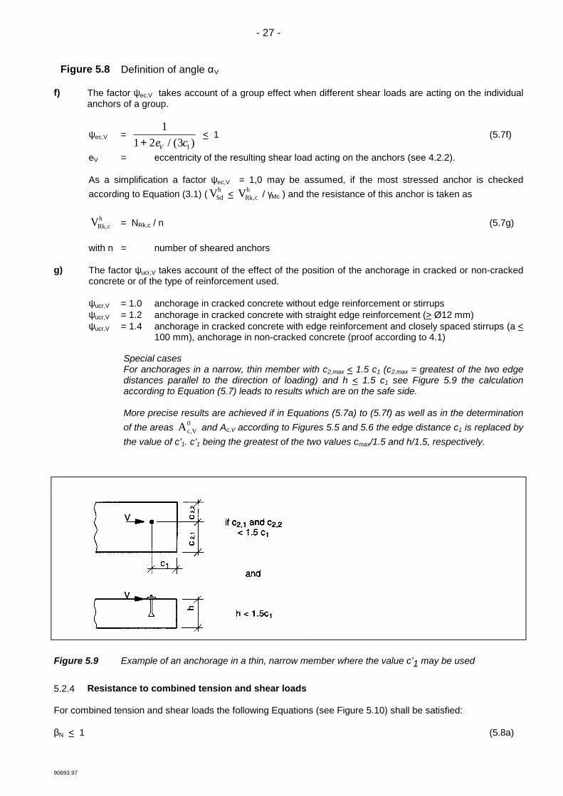
Special casesFor anchorages in a narrow, thin member with c2,max < 1.5 c1 (c2,max = greatest of the two edgedistances parallel to the direction of loading) and h < 1.5 c1 see Figure 5.9 the calculationaccording to Equation (5.7) leads to results which are on the safe side.
More precise results are achieved if in Equations (5.7a) to (5.7f) as well as in the determinationof the areas Ac,V
0 and Ac,V according to Figures 5.5 and 5.6 the edge distance c1 is replaced bythe value of c’1. c’1 being the greatest of the two values cmax/1.5 and h/1.5, respectively.
Figure 5.9 Example of an anchorage in a thin, narrow member where the value c’1 may be used
5.2.4 Resistance to combined tension and shear loads
For combined tension and shear loads the following Equations (see Figure 5.10) shall be satisfied:
βN < 1 (5.8a)

- 28 -
90693.97
βV < 1 (5.8b)
βN + βV < 1.2 (5.8c)
whereβN (βV) ratio between design action and design resistance for tension (shear) loading.In Equation (5.8) the largest value of βN and βV for the different failure modes shall be taken (see 5.2.2.1and 5.2.3.1).
Figure 5.10 Interaction diagram for combined tension and shear loads
In general, Equations (5.8a) to (5.8c) yield conservative results. More accurate results are obtained byEquation (5.9)
(βN)α + (βV)α < 1 (5.9)
with:
βN, βV see Equations (5.8)α = 2.0 if NRd and VRd are governed by steel failureα = 1.5 for all other failure modes
5.3 Design method B
Design method B, is based on a simplified approach in which the design value of the characteristic resistance isconsidered to be independent of the loading direction and the mode of failure.
In case of anchor groups it shall be shown that Equation (3.1) is observed for the most stressed anchor.
The design resistance FRd0 may be used without modification if the spacing scr and the edge distance ccr are
observed. FRd0 , scr and ccr are given in the ETA.
The design resistance shall be calculated according to Equation (5.10) if the actual values for spacing and edgedistance are smaller than the values scr and ccr and larger than or equal to smin and cmin given in the ETA.
FRd = 1n
⋅ AA
c
c0 ⋅ ψs ⋅ ψre . ψucr . FRd
0 [N] (5.10)
n = number of loaded anchors

- 29 -
90693.97
The effect of spacing and edge distance is taken into account by the factors Ac/ Ac0 and ψs. The factor Ac/ Ac
0
shall be calculated according to 5.2.2.4b and the factor ψs shall be calculated according to 5.2.2.4c replacingscr,N and ccr,N by scr and ccr. The effect of a narrowly spaced reinforcement and of non-cracked concrete is takeninto account by the factors ψre and ψucr. The factor ψre is calculated according to 5.2.2.4 d) and factor ψucraccording to 5.2.2.4 f).
In case of shear load with lever arm the characteristic anchor resistance shall be calculated according toEquation (5.5), replacing NRd,s by FRd
0 in Equation (5.5a).The smallest of the values FRd according to Equation (5.10) or VRk,s/γMs according to Equation (5.5) governs.
5.4 Design method C
Design method C is based on a simplified approach in which only one value for the design resistance FRd isgiven, independent of loading direction and mode of failure. The actual spacing and edge distance shall be equalor larger than the values of scr and ccr. FRd, scr and ccr are given in the relevant ETA.
In case of shear load with lever arm the characteristic anchor resistance shall be calculated according toEquation (5.5) replacing NRd,s by FRd in Equation (5.5a).The smallest value of FRd or VRk,s/γMs according to Equation (5.5) governs.
6 Serviceability limit state
6.1 Displacements
The characteristic displacement of the anchor under defined tension and shear loads shall be taken from theETA. It may be assumed that the displacements are a linear function of the applied load. In case of a combinedtension and shear load, the displacements for the tension and shear component of the resultant load should begeometrically added.
In case of shear loads the influence of the hole clearance in the fixture on the expected displacement of thewhole anchorage shall be taken into account.
6.2 Shear load with changing sign
If the shear loads acting on the anchor change their sign several times, appropriate measures shall be taken toavoid a fatigue failure of the anchor steel (e.g. the shear load should be transferred by friction between thefixture and the concrete (e.g. due to a sufficiently high permanent prestressing force)).
Shear loads with changing sign can occur due to temperature variations in the fastened member (e.g. facadeelements). Therefore, either these members are anchored such that no significant shear loads due to therestraint of deformations imposed to the fastened element will occur in the anchor or in shear loading with leverarm (stand-off installation) the bending stresses in the most stressed anchor ∆σ = maxσ - minσ in theserviceability limit state caused by temperature variations should be limited to 100 N/mm2.
7 Additional proofs for ensuring the characteristic resistance of concrete member
7.1 General
The proof of the local transmission of the anchor loads into the concrete member is delivered by using thedesign methods described in this document.
The transmission of the anchor loads to the supports of the concrete member shall be shown for the ultimatelimit state and the serviceability limit state; for this purpose, the normal verifications shall be carried out underdue consideration of the actions introduced by the anchors. For these verifications the additional provisions givenin 7.2 and 7.3 should be taken into account.
If the edge distance of an anchor is smaller than the characteristic edge distance ccr,N (design method A) or ccr(design methods B and C), respectively, then a longitudinal reinforcement of at least ∅ 6 shall be provided at theedge of the member in the area of the anchorage depth.

- 30 -
90693.97
In case of slabs and beams made out of prefabricated units and added cast-in-place concrete, anchor loads maybe transmitted into the prefabricated concrete only if the precast concrete is connected with the cast-in-placeconcrete by a shear reinforcement. If this shear reinforcement between precast and cast-in-place concrete is notpresent, the anchors should be embedded with hef in the added concrete. Otherwise only the loads of suspendedceilings or similar constructions with a load up to 1.0 kN/m2 may be anchored in the precast concrete.
7.2 Shear resistance of concrete member
In general, the shear forces VSd,a caused by anchor loads should not exceed the value
VSd,a = 0.4 VRd1 (7.1)
with:
VRd1 = shear resistance according Eurocode No. 2 [1]
When calculating VSd,a the anchor loads shall be assumed as point loads with a width of load applicationt1 = st1 + 2 hef and t2 = st2 + 2 hef, with st1 (st2) spacing between the outer anchors of a group in direction 1 (2).The active width over which the shear force is transmitted should be calculated according to the theory ofelasticity.

- 31 -
90693.97
Equation (7.1) may be neglected, if one of the following conditions is met
a) The shear force VSd at the support caused by the design actions including the anchor loads is
VSd < 0.8 VRd1 (7.2) b) Under the characteristic actions, the resultant tension force, NSk, of the tensioned fasteners is NSkk < 30 kN
and the spacing, a, between the outermost anchors of adjacent groups or between the outer anchors of agroup and individual anchors satisfies Equation (7.3)
a > 200 . NSk a [mm]; NSk [kN] (7.3) c) The anchor loads are taken up by a hanger reinforcement, which encloses the tension reinforcement and is
anchored at the opposite side of the concrete member. Its distance from an individual anchor or theoutermost anchors of a group should be smaller than hef
If under the characteristic actions, the resultant tension force, NSk, of the tensioned fasteners is NSk > 60 kN,then either the embedment depth of the anchors should be hef > 0,8 h or a hanger reinforcement according toparagraph c) above should be provided.
The necessary checks for ensuring the required shear resistance of the concrete member are summarized inTable 7.1.
Table 7.1 Necessary checks for ensuring the required shear resistance of concrete member
Calculated value of shearforce of the concrete memberunder due consideration of theanchor loads
Spacing between singleanchors and groups ofanchors
NSk[kN]
Proof of calculated shearforce resulting from anchorloads
VSd < 0.8 . VRd1 a > scr,N1) (scr)2) < 60 not required
VSd > 0.8 . VRd1
a > scr,N1) (scr)2)
anda > 200 ⋅ NSk
a > scr,N1) (scr)2)
< 30
< 60
> 60
not required
required:VSd,a < 0.4 . VRd1or hanger reinforcementor hef > 0.8 h
not required, but hangerreinforcement or hef > 0.8 h
1) Design method A2) Design method B and B
7.3 Resistance to splitting forces
In general, the splitting forces caused by anchors should be taken into account in the design of the concretemember. This may be neglected if one of the following conditions is met:
a) The load transfer area is in the compression zone of the concrete member. b) The tension component NSk of the characteristic loads acting on the anchorage (single anchor or group of
anchors) is smaller than 10 kN.

- 32 -
90693.97
c) The tension component NSk is not greater than 30 kN. In addition, for fastenings in slabs and walls a
concentrated reinforcement in both directions is present in the region of the anchorage. The area of thetransverse reinforcement should be at least 60 % of the longitudinal reinforcement required for the actionsdue to anchor loads.
If the characteristic tension load acting on the anchorage is NSk > 30 kN and the anchors are located in thetension zone of the concrete member the splitting forces shall be taken up by reinforcement. As a first indicationfor anchors according to current experience the ratio between splitting force FSp,k and the characteristic tensionload NSk or NRd (displacement controlled anchors) respectively may be taken as
FSp,k = 1.5 NSk torque-controlled expansion anchors (Part 2)= 1.0 NSk undercut anchors (Part 3)= 2.0 NRd deformation-controlled expansion anchors (Part 4)= 0.5 NSk bonded anchors (Part 5)