etakeoff dimension training...
TRANSCRIPT
eTakeoff Dimension Training Guide We realize you may want to skip this training guide and immediately begin trying out eTakeoff Dimension with your own set of drawings. If you can’t curb your enthusiasm, then do the:
QUICK START:
1 - Activate the 15 day Trial to unlock all the takeoff features of eTakeoff Dimension. Go to the TRIAL TAB on the Ribbon Bar. Click on the INSTALL 15 DAY TRIAL button and follow the instructions 2 - Jump to Starting a New Project (click on the link). There you will find simple step-by-step instructions on creating your first project using your own drawing files 3 - Now take a few short minutes to Review the Layout & Workflow Concepts
HOWEVER, if you want to get the maximum benefit for the time spent, continue reading. With the aid of the included Sample Project, it will be the easiest and quickest way to become an expert with eTakeoff Dimension! You can stop any time you wish and come back later. To access the Training Guide again you can either save the Guide to your own computer (using the SAVE options within your browser - PDF format), Print it using the Adobe PDF controls, or Display it again from within eTakeoff Dimension. To access it again from within eTakeoff Dimension:
1 - Go to the FILE Tab, position the cursor on HELP, then move to the right and select “Display On-line Training Guide”
The eTakeoff Dimension Guide will introduce you to the general workflow of Dimension. By following the step-by-step instructions provided here you will learn suggested methods of use as well as helpful hints and shortcuts that will enhance your learning experience. Note that it is beyond the scope of this document to cover all construction disciplines and their specific takeoff methods. Instead, it’s designed to convey the primary features and benefits of Dimension in a logical and efficient manner. Please apply these concepts to your own construction trade. The result will be a very good primer on eTakeoff Dimension upon which you can later build more extensive knowledge of the product. The Guide is broken into 2 sections:

© Copyright 2004-2015 eTakeoff, LLC 2
I - Overview & Basic Takeoff Pages 3-14 1 - Set up the Sample Project 2 - Review the Layout & Workflow Concepts 3 - Begin Measuring 4 - Do a Second Measurement 5 - Measure with an Extension (Assembly)
6 - Sync Measurements 7 - View the Measurement List 8 - Do Additional Takeoff
II - Other Features to Learn Pages 15-36 1 - Settings Tab
2 - Starting a New Project 3 - Moving Project Files and Folders 4 - Additional Takeoff Tools
5 - Editing Measurements 6 - Setting Scales/Detail Scales 7 - Layers 8 - Annotations 9 - Drawing legend 10 - Favorites 11 - Pattern Search (Auto-Count) 12 - Multi-Page Pattern Search 13 - Multiple Drawing Windows 14 - Drawing Hyperlinks 15 - Drawing Compare/Overlays
16 - Extensions (Assemblies) 17 - Polar Mode
18 - Bid Codes 19 - Quantity Worksheet 20 - Excel Integration
21 - Multi-User 22 - Concurrent License Manager 23 - Supported Drawing/Plan Formats
24 -System Requirements
Section I is intended to present the basic features of eTakeoff Dimension in a logical sequence. Steps 1-8 are designed to follow one another. Section II is cafeteria style…pick a topic and experiment! Dimension saves all work automatically, allowing you to return at any time in the future and continue learning.

© Copyright 2004-2015 eTakeoff, LLC 3
You will need to activate the 15 day Trial to use all the takeoff features described in this guide. Go to the
TRIAL Tab on the Ribbon Bar and click on the INSTALL 15 DAY TRIAL button and follow the instructions.
The version used for this Guide is eTakeoff Dimension Premier. See the eTakeoff Dimension Comparison
Chart for a feature comparison of all three versions.
Throughout the guide you will see this video symbol . Click on it to view a short video on the subject.
In addition, any “underlined text” is a link that will display additional Dimension HELP in another Tab or
window in the browser, or will jump to another part of the Guide. Note also that while working in
Dimension, the F1 key is always available to access HELP.
If you haven’t already done so, please view the 10 minute Getting Started With eTakeoff Dimension
video before continuing to get a quick visual overview of the principles discussed in this guide.
Let’s get started!

© Copyright 2004-2015 eTakeoff, LLC 4
I – Overview & Basic Takeoff
1. Set up the Sample Project a. Before we do anything, let’s ensure you’re using the Ribbon Bar Interface.
i. This is the Ribbon Bar Interface - the top of the screen should look like the image below. If this is what you see, then skip to step b.
ii. This is the legacy Tool Bar Interface – It looks like this:
iii. If you see the Tool Bar Interface, then do the following: 1. Click on the ADMIN menu item at the top of the screen 2. Select User Preferences 3. The User Preferences window will open:
iv. Click on the LOOK tab, and check the box next to “Use ribbon bar.” Click OK. Dimension will close and restart with the Ribbon Bar interface.
b. Let’s continue! We first need to import a Sample Project that will contain all the Drawing files and Project settings that we will use in this Guide.

© Copyright 2004-2015 eTakeoff, LLC 5
i. Click the FILE tab and position the cursor on PROJECT BACKUP…then move the cursor to the right and click on the RESTORE PROJECT option
ii. This will open a Windows dialog box that will allow you select the Sample Project to restore. Open the eTakeoffSamples Folder then open LaQuintaHotel and finally, open the LA QUINTA HOTEL – Simple Sample.tpxzip file.
1. The dialog box will close and Dimension will open the Project Properties window.
iii. Project Properties contains static information about the project (such as project description) as well as project options such as a default project Scale, Auto-Backup, etc.
iv. These fields are optional, so for now let’s just click OK continue v. The La Quinta Hotel project will open and the first drawing in the project will be
displayed in the Dimension panel 1. Don’t worry about messing up the project while working through this
guide. You can always delete the project and start over. a. To delete a project, go to the Home Tab and click on the EDIT button in
the Project section of the Ribbon Bar. The Project Properties window will open. Delete the project by clicking on the DELETE button on the bottom left. You can now simply restore the La Quinta Hotel project again.
b. Also, note that the PROJECT BACKUP options in the FILE Tab are very useful if you need to create off-site backups or wish to transfer the project to another computer to continue working on the project (at home/etc.). Especially useful is the Backup and Zip option, which will create a single zip file of the complete project including all drawings, measurements, annotations, etc.
vi. In the future, if you want to start a new project with your own drawing files, see Starting a New Project.
2. Review the Layout and Workflow Concepts
a. Review the Ribbon Bar Interface. i. There are 8 Tabs going across the top of the Ribbon Bar that separate various
areas of functionality in Dimension. Click through the various Tabs to review. If you hover the cursor over any of the buttons, you will see Tooltips appear that will provide useful information regarding the use of that button.
ii. The Home Tab 1. Much of your daily workflow will be contained in the Home Tab. The five
simple sections cover Projects, Navigation, Takeoff, Measurement Edits and Scale.
2. Again, note the usefulness of the Tooltips – they teach the basic use of the system as you progress
iii. Context Help 1. Click on the green question mark on the far right side of the Ribbon Bar.
Then click on the area in question on the Ribbon Bar. The Help system will open to that specific area of Help. You may have to look down the page for the topic if the HELP page is too short to scroll.
iv. The Quick Access Toolbar 1. The Quick Access Toolbar is a single toolbar consisting of commonly used
buttons from the other Tabs. It is user configurable, and overcomes the

© Copyright 2004-2015 eTakeoff, LLC 6
objection to the ribbon bar which is initially easier to learn, but requires more jumping between tabs once familiar with system
2. When you find that you are consistently using a particular button on any
tab, you can right click on that button and select “Add to Quick Access Toolbar” to add the button to the Quick Access Toolbar on-the-fly. If you wish, you can later click on the down arrow at the end of the Quick Access Toolbar and rearrange the buttons in any order you wish.
3. You can park the Quick Access Toolbar above or below the Ribbon Bar
b. Note Dimension’s Default View
i. The Drawing Area is in the center between the 2 Control Panels ii. Control panels
1. The Control Panels contain individual user-selected Controls. Clicking on the little down arrow on any header will display a list of Controls to choose from. You can display one, both, or none of the control panels.
2. The Control Panels are dockable a. Practice clicking on the header and moving the control panel to
another area or monitor. To re-dock the control panel in its normal position, drag the header to the far side of the screen. When the CURSOR reaches the edge of the screen you will see the control panel “ghost” position itself. Release the cursor button and the panel will be correctly docked.
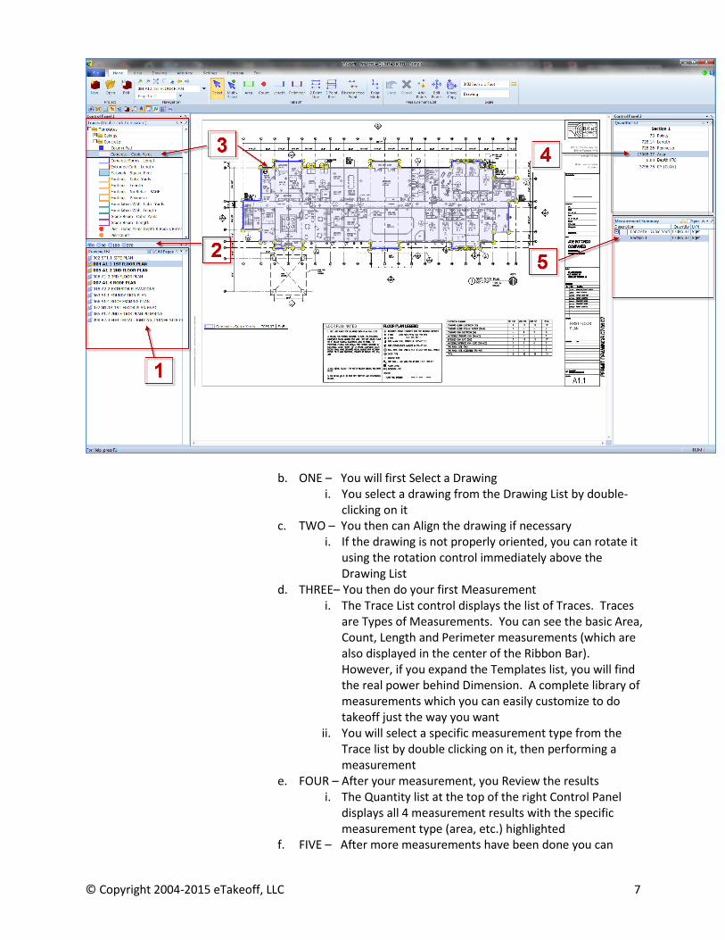
3. Note the logical “clockwise” workflow organization in Dimension. Review the image below while we step through the general workflow.
a. Starting at the lower left Control panel, follow the workflow steps 1 – 5 as you move clockwise around the screen
© Copyright 2004-2015 eTakeoff, LLC 7
b. ONE – You will first Select a Drawing i. You select a drawing from the Drawing List by double-
clicking on it c. TWO – You then can Align the drawing if necessary
i. If the drawing is not properly oriented, you can rotate it using the rotation control immediately above the Drawing List
d. THREE– You then do your first Measurement i. The Trace List control displays the list of Traces. Traces
are Types of Measurements. You can see the basic Area, Count, Length and Perimeter measurements (which are also displayed in the center of the Ribbon Bar). However, if you expand the Templates list, you will find the real power behind Dimension. A complete library of measurements which you can easily customize to do takeoff just the way you want
ii. You will select a specific measurement type from the Trace list by double clicking on it, then performing a measurement
e. FOUR – After your measurement, you Review the results i. The Quantity list at the top of the right Control Panel
displays all 4 measurement results with the specific measurement type (area, etc.) highlighted
f. FIVE – After more measurements have been done you can

© Copyright 2004-2015 eTakeoff, LLC 8
review your work in the Measurement Summary i. The Measurement Summary Control is at the bottom of
the right Control Panel. It provides a summary view of all measurements in this drawing. The Measurement List
control in the header will open a List of all measurements in the entire Project
4. The clockwise workflow makes it easy to understand where you are at all times
c. Drawing navigation is very simple. Practice this. i. Use the mouse scroll-wheel to zoom in and out of the cursor location
ii. Panning – press both left/right mouse buttons and drag the drawing iii. Double-click on the Drawing list to select another drawing iv. Note the cursor will change appearance based on the selected mode.
1. If you click on a Ribbon Bar button that puts the mouse into a different mode, a small “mode indicator” will display
i. Examples: 2. This eliminates the need to continually reference the Ribbon Bar to
determine what will happen with the next mouse click. The indicator will change for a variety of takeoff modes (select, multi-select, measurements, 2 point line, edit points, etc.) Experiment.
d. If you’re doing the QUICK START, then you’re finished! Return to the Beginning
3. Begin Measuring a. Now let’s do some work. Double click Drawing 004 – First Floor Plan b. Set the Scale
i. Either set scale here or wait until step c.iii.1 below ii. If you wish to set the scale here, click the SET SCALE button in the Scale section of
the ribbon bar. The Drawing Scale Edit Dialog will open. iii. There are 3 ways to set the scale
1. Select a scale by clicking on the pull-down next to “standard scale”. This Drawing is 3/32” = 1 Foot. Select the proper scale.
2. The second method is to simply enter the scale in English in the existing fields (3/32=1 foot will be displayed)
3. The third method allows you to calibrate the scale based on 2 points of known distance. Click on the CALIBRATE button then click on 2 points of a known distance on the plan, enter the actual distance and the scale will be set accordingly
4. Close OK to close the scale dialog c. Do an Area measurement
i. Hover over the Area Button on the Ribbon Bar to show the Tooltips and note the SHORTCUT keys described on the bottom – refer to these often as they will give you hints on how to use Dimension
ii. Click on the AREA button on the Ribbon Bar iii. Now let’s perform a measurement
1. Note that if you have NOT already set the scale, then the Scale Selection dialog will appear before you begin measuring to let you choose the scale from the pull-down.

© Copyright 2004-2015 eTakeoff, LLC 9
a. If you set the scale here, then after selecting the scale from the pull-down, be sure to click on the USE SELECTED button to close the dialog. If you click on the Set Scale button the full scale dialog will open with all scale options available.
2. ALWAYS MEASURE AREA IN A CLOCKWISE DIRECTION – measuring counter-clockwise creates a negative area and is used to create cutouts (see Cutouts below)
3. Now click the corners of the area you wish to measure a. If you make a mistake, you can cancel the entire measurement
by either clicking on the red CANCEL button in the Measurement Edit section of the Ribbon Bar, or simply press the ESC key. If you only want to correct the last segment, click the UNDO button just to the left of the CANCEL button, or press the BACKSPACE key. You can repeat this process to continue reversing previous measurement segments.
b. While clicking the corners of the area measurement, you can hold the left mouse button down & pause to auto-zoom into the drawing for accurate placement. Also, if you’re zoomed in and reach the edge of the drawing window while measuring, you can pan across the drawing by holding both mouse buttons down simultaneously and dragging the drawing
4. End the measurement (S-key or Enter key) a. Note that you can also force the measurement line into
horizontal or vertical by holding the CTRL key down while measuring. This temporarily engages POLAR MODE. There are also other options to “rubber band” the cursor, etc. You can go to Polar Mode later for more information.
b. You can also display the cursor with crosshairs by pressing the H key. Experiment with these options.
iv. Note the measurement result in the Quantity List in the upper right Control Panel 1. Remember, all four quantity measurements display – the one highlighted
is this measurement (area) 2. The 4 quantities also display in the Measurement List
v. Enter a Location 1. Again hover over the Area button to show the Tool Tip – note the D key
shortcut is described (the Measurement Description) 2. Press the D key and enter the Description (a Location or other secondary
code – this will be the secondary sort in the Measurement Summary and the Measurement List
vi. Now check the Measurement Summary in the lower right Control Panel 1. The Measurement SUMMARY shows all measurements on this drawing,
not the entire project. 2. Note the secondary level under the Trace (the measurement type) which
displays the Location or other code you entered d. EZ Trace Creation
i. Again, hover over the AREA button to review the Tooltip. Note the description of the Z key

© Copyright 2004-2015 eTakeoff, LLC 10
ii. EZ Trace Creation allows you to create new Traces on-the-fly while doing normal takeoff. You have the ability to custom create your own library of Traces (Measurement Types) to be used again across ALL PROJECTS, not just this one.
iii. Press the Z key and enter a new description (Slab On Grade – or other common area measurement)
iv. Select a new Fill Style, Color and Transparency (experiment) and click OK 1. Note the result of your selections in the preview window. This will give
you a visual representation of what your new Trace will look like v. See the new Trace in the Trace List at the top of the left Control Panel?
1. Again, you just created this new Trace as a by-product of normal takeoff 2. It’s been added to your master Trace Library and can be used across all
PROJECTS, not just this drawing 3. It is very easy to later organize your new Traces that you’ve created
a. Go to the SETTINGS Tab and click on the Edit Traces button to open the Trace Maintenance dialog.
b. The default display will show your new Trace in the list with the other standard Traces (area, etc.) You can now organize your traces by simply clicking on the new trace and dragging and dropping it into the appropriate folder (Do this later if you wish to experiment)
i. You can create new folders by simply right clicking on any folder
e. NOTE – Deleting Measurements i. As you experiment, you may find it necessary to quickly delete your
measurements and start with a clean drawing. It’s easy to quickly delete all measurements and annotations in a drawing
ii. To delete a single measurement, just click on the measurement to select it, then press the Delete key
iii. You can also delete multiple measurements 1. Click on the Multi-Select Button on the Ribbon Bar 2. Click the left mouse button on the upper left section of the drawing 3. Keeping the mouse button depressed, drag a rectangle to cover all
measurements or the entire drawing. This will automatically select all measurements/annotations within the rectangle. Note that to delete a measurement or summary, it must be visible and completely contained within the rectangle.
4. Press the delete key on your keyboard iv. For more instruction on editing existing measurements, see Editing
Measurements below
4. Do a Second Measurement a. Use the Trace you just created (Slab On Grade)
i. Double-click on the Trace in the Trace List ii. Perform the measurement (end with S Key to Stop measurement)
iii. Use the D key to enter a Description (Location or other secondary code) iv. View the Measurement Summary results in the Control Panel

© Copyright 2004-2015 eTakeoff, LLC 11
5. Measure with an Extension (Assembly) a. The four general measurement types are area, length, perimeter and count. These four
are shown in the Trace List control panel and are repeated in the Ribbon Bar. However, expanding the “Template” folder will reveal all the pre-defined traces included with Dimension. The real power behind Dimension is utilized with pre-defined traces, whether you use the included set or you add your own. Traces can also contain Extensions (Assemblies) that are very powerful and can calculate complete construction objects with one measurement. Let’s try an example.
b. Expand the Trace List (Templates) and find this Trace under Frame & Drywall: i. 2x4 Wall – Length, Studs & Drywall
c. Double click on the Trace to begin a measurement
i. Begin measuring a wall on the drawing. Notice the symbol attached to the first point of the measurement. This indicates there is an Extension (Assembly) attached to this Trace. When finished, Stop the Trace with the S key. Check the Quantity List for the measurement results.
ii. Note that in addition to the Length and other standard quantities (area, perimeter, & count), there are several other variables listed that are part of the Wall Extension (or assembly). Several of these have input fields that are color coded and are waiting for your input to complete the Extension. As you enter the additional information, note how the Extension calculates the additional quantities for studs and drywall. Using custom formulas and logic, you can create your own simple or sophisticated Traces that can generate complete construction objects such as a wall with all of its individual components (plate, sheetrock, nails, insulation, etc.)
iii. Press the D key and enter a Location or other secondary code.
6. Sync Measurements a. Let’s learn a little more about the Measurement Summary in the right Control Panel b. Review your measurements so far
i. Note that you can always double click on a particular measurement in the Measurement Summary list to see it selected on the drawing. However, if you select a measurement on the DRAWING by clicking on it, or take off a new measurement, it will only display in the Measurement Summary if the Summary list is positioned so the measurement will be visible
1. This lets you keep the Measurement List positioned and configured the way you want while you move around the drawing and do further takeoff or selecting of measurements, etc.
ii. As the list of measurements grows, it may be useful to Sync the drawing measurements with the Measurement Summary
1. Checking the Sync box in the Measurement Summary header will Synchronize all measurements. If you click on an existing measurement on the drawing, or take off a new measurement, the Measurement Summary will position itself to show and highlight that measurement.
a. Drawing 005 Second Floor Plan has more takeoff if you’d like to experiment more with this feature
© Copyright 2004-2015 eTakeoff, LLC 12
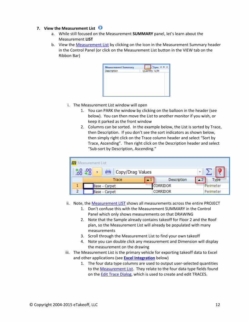
7. View the Measurement List
a. While still focused on the Measurement SUMMARY panel, let’s learn about the Measurement LIST
b. View the Measurement List by clicking on the Icon in the Measurement Summary header in the Control Panel (or click on the Measurement List button in the VIEW tab on the Ribbon Bar)
i. The Measurement List window will open 1. You can PARK the window by clicking on the balloon in the header (see
below). You can then move the List to another monitor if you wish, or keep it parked as the front window
2. Columns can be sorted. In the example below, the List is sorted by Trace, then Description. If you don’t see the sort indicators as shown below, then simply right click on the Trace column header and select “Sort by Trace, Ascending”. Then right click on the Description header and select “Sub-sort by Description, Ascending.”
ii. Note, the Measurement LIST shows all measurements across the entire PROJECT 1. Don’t confuse this with the Measurement SUMMARY in the Control
Panel which only shows measurements on that DRAWING 2. Note that the Sample already contains takeoff for Floor 2 and the Roof
plan, so the Measurement List will already be populated with many measurements
3. Scroll through the Measurement List to find your own takeoff 4. Note you can double click any measurement and Dimension will display
the measurement on the drawing iii. The Measurement List is the primary vehicle for exporting takeoff data to Excel
and other applications (see Excel Integration below) 1. The four data type columns are used to output user-selected quantities
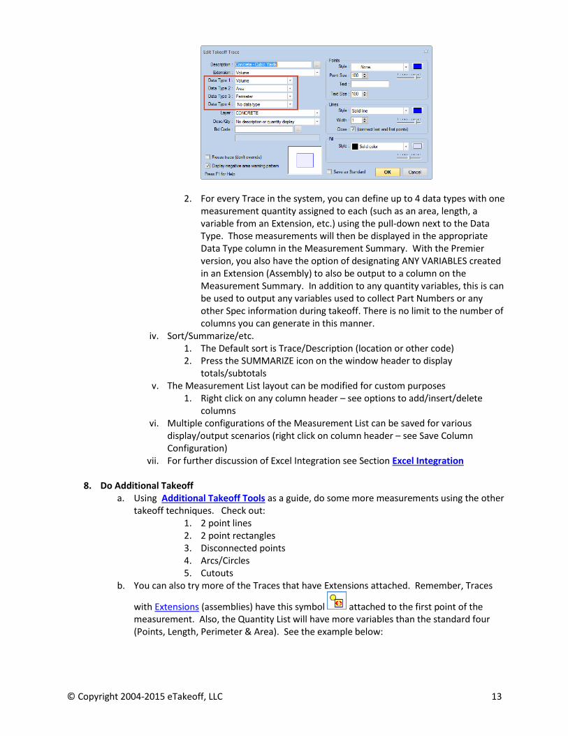
to the Measurement List. They relate to the four data type fields found on the Edit Trace Dialog, which is used to create and edit TRACES.
© Copyright 2004-2015 eTakeoff, LLC 13
2. For every Trace in the system, you can define up to 4 data types with one
measurement quantity assigned to each (such as an area, length, a variable from an Extension, etc.) using the pull-down next to the Data Type. Those measurements will then be displayed in the appropriate Data Type column in the Measurement Summary. With the Premier version, you also have the option of designating ANY VARIABLES created in an Extension (Assembly) to also be output to a column on the Measurement Summary. In addition to any quantity variables, this is can be used to output any variables used to collect Part Numbers or any other Spec information during takeoff. There is no limit to the number of columns you can generate in this manner.
iv. Sort/Summarize/etc. 1. The Default sort is Trace/Description (location or other code) 2. Press the SUMMARIZE icon on the window header to display
totals/subtotals v. The Measurement List layout can be modified for custom purposes
1. Right click on any column header – see options to add/insert/delete columns
vi. Multiple configurations of the Measurement List can be saved for various display/output scenarios (right click on column header – see Save Column Configuration)
vii. For further discussion of Excel Integration see Section Excel Integration
8. Do Additional Takeoff a. Using Additional Takeoff Tools as a guide, do some more measurements using the other
takeoff techniques. Check out: 1. 2 point lines 2. 2 point rectangles 3. Disconnected points 4. Arcs/Circles 5. Cutouts
b. You can also try more of the Traces that have Extensions attached. Remember, Traces
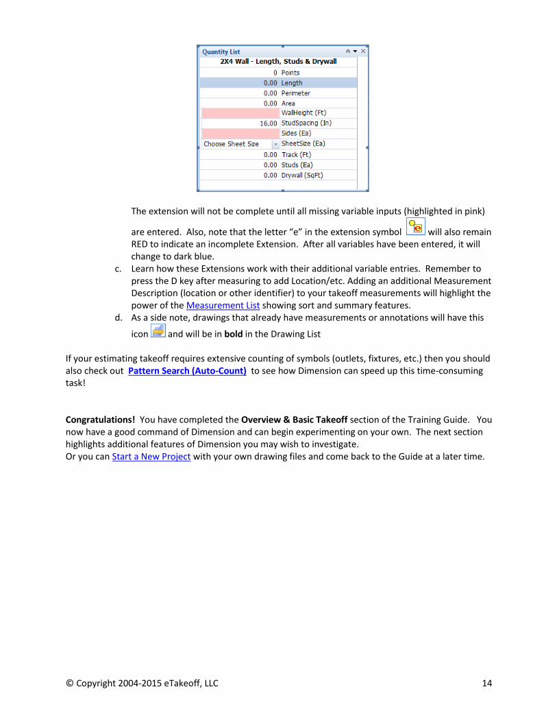
with Extensions (assemblies) have this symbol attached to the first point of the measurement. Also, the Quantity List will have more variables than the standard four (Points, Length, Perimeter & Area). See the example below:
© Copyright 2004-2015 eTakeoff, LLC 14
The extension will not be complete until all missing variable inputs (highlighted in pink)
are entered. Also, note that the letter “e” in the extension symbol will also remain RED to indicate an incomplete Extension. After all variables have been entered, it will change to dark blue.
c. Learn how these Extensions work with their additional variable entries. Remember to press the D key after measuring to add Location/etc. Adding an additional Measurement Description (location or other identifier) to your takeoff measurements will highlight the power of the Measurement List showing sort and summary features.
d. As a side note, drawings that already have measurements or annotations will have this
icon and will be in bold in the Drawing List
If your estimating takeoff requires extensive counting of symbols (outlets, fixtures, etc.) then you should also check out Pattern Search (Auto-Count) to see how Dimension can speed up this time-consuming task! Congratulations! You have completed the Overview & Basic Takeoff section of the Training Guide. You now have a good command of Dimension and can begin experimenting on your own. The next section highlights additional features of Dimension you may wish to investigate. Or you can Start a New Project with your own drawing files and come back to the Guide at a later time.

© Copyright 2004-2015 eTakeoff, LLC 15
II - Other Features to Learn
1. Settings Tab a. The Settings Tab contains the controls that determine how Dimension functions. b. Note especially the User Preferences button. Here you will find many settings that will
allow you to personalize Dimension. Study the User Preferences Help link to learn more about each of the Preference options.
2. Starting a New Project a. A Project is essentially a SINGLE PROJECT FOLDER (a Windows folder) that contains all
drawings used in the project. You can have subfolders within the Project folder if you wish to further organize your drawings. You can keep all your Project Folders in the eTakeoff Projects Folder that was created when you installed eTakeoff Dimension, or you can create your own Project Folder structure on your hard drive or on a network drive for storing your drawings.
b. When you create a NEW Project in Dimension, you are telling Dimension where the Project Folder is located. Dimension will then reference the drawing files in the Project Folder and store all measurements and actions on those drawings in the Dimension Project Database. The original drawing files in the Project Folder are NOT copied or modified in any way and do not need to be converted to a native format (TIF, etc.)
i. Before continuing, ensure that you have created the Project Folder in Windows and have placed all the appropriate drawing files within it.
c. On the HOME Tab, click on the New Project button at the far left of the Ribbon Bar. The Project Folder Selection window will open.
i. Find and Select the Project Folder that contains your drawings and click OK. d. The Project Properties window will open.
i. The Project Properties Window contains static information about the project (such as project description) as well as project options (default Project Scale, Auto-Backup, etc.)
ii. Fill in any fields you wish to define, then click OK to continue e. The ADD DRAWINGS TO PROJECT dialog will open
i. It will display all the drawing files found in the Project Folder and its subfolders ii. Select those drawings you wish to include in the project. You can select/deselect
all of the drawings by clicking directly on the folder icon, or select just those drawings you wish by clicking in the box next to them.
iii. Click on the ADD button to add the drawings to the project. iv. Your project will open and the first drawing in the project will be displayed in the
Dimension drawing panel. f. If you’re doing the QUICK START, then Review the Layout & Workflow Concepts
3. Moving Project Files and Folders
a. It is often necessary to move a project folder and it’s drawings to another location. Because the Dimension database containing all project measurements and other work is pointing to an internal folder location, you should NOT move the folder using windows explorer. Instead, use the MOVE function within Dimension to accomplish this quickly and easily
i. Ensure the project is already OPEN in Dimension. Then click the EDIT button in the Project section of the Ribbon Bar. Click the MOVE button in the upper right corner of the Project Properties Window (see the image below)

© Copyright 2004-2015 eTakeoff, LLC 16
ii. Follow the instructions. View the video link to see this in action
4. Additional Takeoff Tools a. 2 Point Lines
i. Use to quickly take off line segments ii. Don’t forget to end the last measurement with the S key
b. 2 Point Rectangles i. Quickly take off squares/rectangles
ii. Stop measurement with the S key c. Arcs & Circles
i. While measuring, continue clicking on all points required to define the measurement, then when you get to the beginning of the arc, click 3 points – the beginning, middle and end of the arc
ii. Then press the C key shortcut – you will see each point on the arc that Dimension has generated.
iii. For a Circle, just make 2 equal arcs (each one half of the circle) iv. Continue measuring (if there are more points needed) and then Stop the
measurement with the S key. d. Disconnected Points
i. Disconnected Points are useful for taking off several measurements of the same type (areas, line segments) but accumulating the total as if one measurement
1. Start an area measurement 2. Click the points for the first measurement (or group of points) 3. Instead of Stopping the measurement with the S key, click on the
Disconnected Points button and then begin the next area measurement. a. You can use the G shortcut key instead of clicking on the
disconnected point button to start the next Group of points, repeating these steps to quickly create several groups of measurement points
4. Continue until all areas have been measured. Don’t forget to Stop the last measurement with the S key.

© Copyright 2004-2015 eTakeoff, LLC 17
5. All these groups of points will be considered one complete measurement, i.e. selecting one group of points will select them all. If you press the D key to add a description (location/etc.) it will be applied to all the points in the group.
e. Cutouts i. Cut-Outs are measurements that subtract one Area from another Area, such as
an inlay ii. Start an Area measurement (measuring clockwise) and click the points outlining
the area iii. When complete, click on the Disconnected Point button (or press the G shortcut
key) 1. You do not need to stop the measurement with the S key, although you
can iv. Now begin measuring the cutout area (within the first area) by clicking on the
first point of the cutout area and begin measuring COUNTER-CLOCKWISE. 1. You can press Disconnected Points again (or use the G key shortcut) to
create another cutout if you wish. v. When finished, press the S key to Stop the measurement and view the results in
the Quantity List vi. View the training video to see how to assign a new Trace to the cutout itself
f. Specialty Extensions Click on the links below to learn more about the Pre-Set Specialty extensions
1. Riser 2. Joist 3. Roll 4. Grid
You can customize these for your own use. They are extremely important to some construction trades.
5. Editing Measurements a. There are many tools in the Measurement Edit section of the Ribbon Bar to correct any
measurement errors. i. If you make a mistake during a measurement, you can cancel the entire
measurement by either clicking on the red CANCEL button in the Measurement Edit section of the Ribbon Bar, or simply press the ESC key. If you only want to correct the last segment, click the UNDO button just to the left of the CANCEL button, or press the BACKSPACE key. You can repeat this process to continue reversing previous measurement segments.
ii. If you wish to edit an existing measurement, use the ADD POINTS, EDIT POINTS or MOVE/COPY buttons in the Measurement Edit section of the Ribbon Bar.
iii. Overlapping Measurements - If you’ve done extensive takeoff, you may find measurements which overlap or are so close together it’s difficult to select the right measurement.
1. Ensure you’re in Select mode (the Select button in the Ribbon Bar will be highlighted and the cursor will have a small blue arrow to the right)
2. Click on one of the measurements to select it 3. Right click and choose Select From List (at bottom of context list) 4. Dialog will open with all measurements that are in close proximity 5. Select the measurement you want from the list

© Copyright 2004-2015 eTakeoff, LLC 18
6. Setting Scales /Detail Scales a. Familiarize yourself with the various methods to set the Drawing Scale b. View the video to learn more about Calibrating scales c. Detail Scales – Dimension allows setting multiple scales on a single drawing. This is
typically used for detail drawings that have more than one scale. Detail Scales in on the DRAWING TAB, in the Scale Section.
i. In the Drawing List, find the 200 A4-INT ELEVATIONS drawing and double click to select it. Note there are several elevations on this drawing. On the right side of the Home Tab Ribbon Bar is the Scale section. The drawing scale has already been set at ½ inch = 1 foot.
ii. Note also the section of the drawing that has a blue outline. This denotes a detail scale – an area of the drawing that has a different scale than the drawing scale. If you click on any existing measurement inside the detail section, you will note that the scale in the Ribbon Bar changes for that measurement because this section of the drawing has a scale of ¼ inch = 1 foot (don’t change any measurements in this Detail Section since it will be used for another example later)
iii. Let’s create another detail Scale section for Elevation B (3rd from the left on the top row). Go to the DRAWING tab, and click on the DETAIL SCALES button in the Scale section. The Detail Scale List dialog opens. There is already one Detail Scale listed.
iv. Let’s add another by clicking on the ADD button. The Detail Scale Edit Dialog will open. Enter a description of Elevation B, and go to the Standard Scale pulldown and select 1/8” = 1 foot (the actual scale is ½ “= 1 foot, but we’ll select the 1/8“option to illustrate the concept).
v. Then, click on the SET BORDER button – the dialog will close. Follow the hint window instructions to create a square around Elevation B. When finished, click on OK, then close the Dialog.
vi. Dimension has now created a new Detail scale section and labeled it Elevation A.

© Copyright 2004-2015 eTakeoff, LLC 19
vii. Now do an area measurement in Elevation B and another measurement
elsewhere in the drawing. Note how the scale automatically changes as you measure inside and outside the boundaries of the Detail scale section.
viii. You can have as many Detail Scale sections as you wish 1. Also, note that you can drag a detail scale into the Favorites control and
then reuse the Detail Scale by dragging and dropping onto drawings
7. Layers a. Layers in Dimension work like layers in CAD drawings. Measurements and annotations
can be assigned to layers. The layers can then be turned on and off to show or hide the measurements and annotations assigned to the layer.
i. You create a master list of Layers by clicking on the Edit Layers button on the Settings tab.
ii. You can have an unlimited number of layers iii. You can also assign a default layer to any Trace using the Edit Traces button on
the Settings tab. b. The Control Panel contains the Layer Control to display layers
8. Annotations a. Dimension has an extensive library of annotation tools to add notes and graphics to the
drawings. Click on the HELP link above to get a complete overview of the Annotation Tab
9. Drawing Legend a. The Drawing Legend displays a grid of all traces used in the drawing.
i. Go to the VIEW Tab on the Ribbon Bar. ii. If no measurements have ever been done on the drawing, the Drawing Legend
button will be grayed out iii. If measurements exist, click on the Drawing Legend button to turn on the
drawing legend 1. You can drag the Legend to any location on the drawing 2. The Drawing Legend is modal. Clicking the button will turn the mode
on/off iv. You can configure the look of the Drawing Legend by right clicking on the
Drawing Legend. Experiment, using the many options listed. The NEW DRAWING LEGEND option will let you create a default look for new drawings.
10. Favorites
a. Favorites are an Dimension exclusive that will make you much more productive when faced with repetitive tasks
b. Add Favorites to the right Control Panel i. Click on the down arrow on the right side of the Control Panel 2 header
ii. Select Favorites from the list c. Create a Project Favorite
i. Go to Drawing 005 – 2nd Floor Plan ii. Click on Multi-Select on the Ribbon Bar (Home Tab) and create a rectangle
around the entire 2nd floor takeoff
© Copyright 2004-2015 eTakeoff, LLC 20
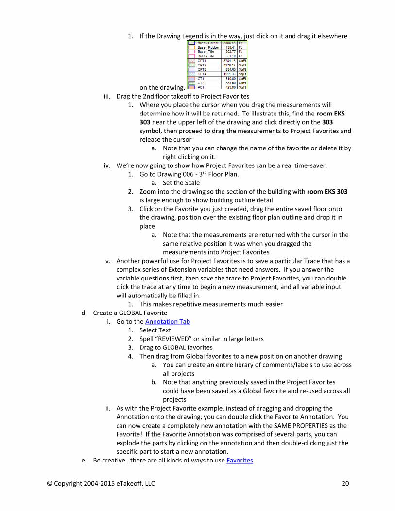
1. If the Drawing Legend is in the way, just click on it and drag it elsewhere
on the drawing. iii. Drag the 2nd floor takeoff to Project Favorites
1. Where you place the cursor when you drag the measurements will determine how it will be returned. To illustrate this, find the room EKS 303 near the upper left of the drawing and click directly on the 303 symbol, then proceed to drag the measurements to Project Favorites and release the cursor
a. Note that you can change the name of the favorite or delete it by right clicking on it.
iv. We’re now going to show how Project Favorites can be a real time-saver. 1. Go to Drawing 006 - 3rd Floor Plan.
a. Set the Scale 2. Zoom into the drawing so the section of the building with room EKS 303
is large enough to show building outline detail 3. Click on the Favorite you just created, drag the entire saved floor onto
the drawing, position over the existing floor plan outline and drop it in place
a. Note that the measurements are returned with the cursor in the same relative position it was when you dragged the measurements into Project Favorites
v. Another powerful use for Project Favorites is to save a particular Trace that has a complex series of Extension variables that need answers. If you answer the variable questions first, then save the trace to Project Favorites, you can double click the trace at any time to begin a new measurement, and all variable input will automatically be filled in.
1. This makes repetitive measurements much easier d. Create a GLOBAL Favorite
i. Go to the Annotation Tab 1. Select Text 2. Spell “REVIEWED” or similar in large letters 3. Drag to GLOBAL favorites 4. Then drag from Global favorites to a new position on another drawing
a. You can create an entire library of comments/labels to use across all projects
b. Note that anything previously saved in the Project Favorites could have been saved as a Global favorite and re-used across all projects
ii. As with the Project Favorite example, instead of dragging and dropping the Annotation onto the drawing, you can double click the Favorite Annotation. You can now create a completely new annotation with the SAME PROPERTIES as the Favorite! If the Favorite Annotation was comprised of several parts, you can explode the parts by clicking on the annotation and then double-clicking just the specific part to start a new annotation.
e. Be creative…there are all kinds of ways to use Favorites

© Copyright 2004-2015 eTakeoff, LLC 21
11. Pattern Search (Autocount) (Premier version)
a. Pattern Search is a powerful tool to search for multiple symbols across a drawing (Auto-Count)
i. From the HOME Tab, go to the Drawing List and Double Click on Drawing 090 – Electrical Lighting
1. You may have to use the Rotation control in the Left Control Panel to properly orient the drawing
ii. If the scale has not already been set, click on the scale button on the far right end of the Ribbon Bar and set the scale.
iii. Now let’s specify what we’re going to search for. It isn’t necessary to perform this step at this time; it can be done later.
1. Expand the Templates list in the Trace List panel in Control Panel 1. Then expand Fire & Security. Select the Smoke Detector – Count. Ensure you click ONCE on the trace so that trace is selected/highlighted.
iv. Now let’s begin the Search. Click on the Drawing Tab on the Ribbon Bar v. At the far right on the Ribbon Bar you will find the Pattern Search (auto-count)
section vi. The first step is to specify the search area. The search will be faster if you first
eliminate text and other miscellaneous areas of the drawing. Also, you may wish to search a specific room or section of the drawing
1. There are 2 options for specifying the search area…a rectangle for simple searches or polygon for more complex search areas. For our purposes we will use the rectangle
vii. Click on the ADD SEARCH RECTANGLE button 1. A dialog will open allowing you to name the search area. Enter “Entire
Floor” or other identifier 2. You will now see the cursor with a small Search Area indicator to the
right of it 3. Starting at the upper left corner of the desired search “rectangle”, click
the cursor once, then go to the bottom right corner of the intended search “rectangle” and click again.
4. You should see a search area similar to this image – ignore the red rectangle for now

© Copyright 2004-2015 eTakeoff, LLC 22
5. Ensure that the entire search area is covered…don’t include any of the drawing description area on the right side of the drawing. If you made a mistake, simply select the search area with the cursor, press the delete key and go back to step viii.
6. After the search area is displayed, click anywhere OUTSIDE the search area to hide the search pattern…this will make it easier to view the drawing while performing the search. Note that you can show the search area any time by clicking on the SHOW SEARCH AREAS button.
a. If you wish to delete a search area, ensure it is visible (click on the SHOW SEARCH AREAS button if necessary). Then select the search area (or multi-select if there is more than one area) and press the Delete key.
viii. Now click on the START/RESUME button to begin the search process 1. A Hint window will open which will instruct you to draw a rectangle
around the specific pattern/symbol you wish to search for 2. Zoom into the drawing, focusing on the area highlighted by the red
triangle in the image above
3. Zoom in close to the Smoke Detector symbol (remember, if you need to pan across the drawing you can click both mouse buttons and drag). Starting in the upper left corner, drag a tight rectangle around the Smoke Detector symbol similar to the example above.
4. When you release the cursor, the Edit Pattern for Search dialog will open. Note the selected pattern is now shown in the display area.
a. Go to the Search Area field near the top of the dialog and click on the pull-down arrow. Select the Search Area you created earlier (Entire Floor)
b. You can, depending on the quality of the drawing, use the editing tools at the top of the dialog to clean up the search pattern
c. You can also specify the percentage of pixel matching (again, dependent on drawing quality) to ensure a better search. Enter 80% here.
d. Note in the Trace field the Smoke Detector trace is already specified since you had selected it in the Trace List before starting the search (step 11.a.iii.1 above)
i. If you did not perform that earlier selection, you can do it now by clicking on the SELECT button and finding the Smoke Detector trace in the trace list (under Fire & Security)

© Copyright 2004-2015 eTakeoff, LLC 23
ix. Now click the SEARCH button at the upper right of the dialog to start the actual search
1. When the search is completed, you will see a display of every match (it should be similar to this image):
2. Note that you can immediately tell that one of the matches is a HEAT
DETECTOR , not a Smoke Detector (outlined in the red rectangle) 3. Using the cursor, let’s click on the incorrect match (the Heat Detector) to
unselect it for now (it will turn white). Do the same for any other obvious mismatches
4. Here’s a very powerful (and Patented) feature of Dimension. Note the little blue “expand” box in the lower right corner of the first match. Click on that box and drag the image out a little over a ¼”. You should see something similar to the image below:
5. When we originally began the search, we kept the search selection very tight to ensure an accurate match. However, after completing the search it is useful to expand the matches to ensure there’s nothing critical that was missed. In this case, note the Smoke Detector with Auxiliary match that is now revealed:
© Copyright 2004-2015 eTakeoff, LLC 24
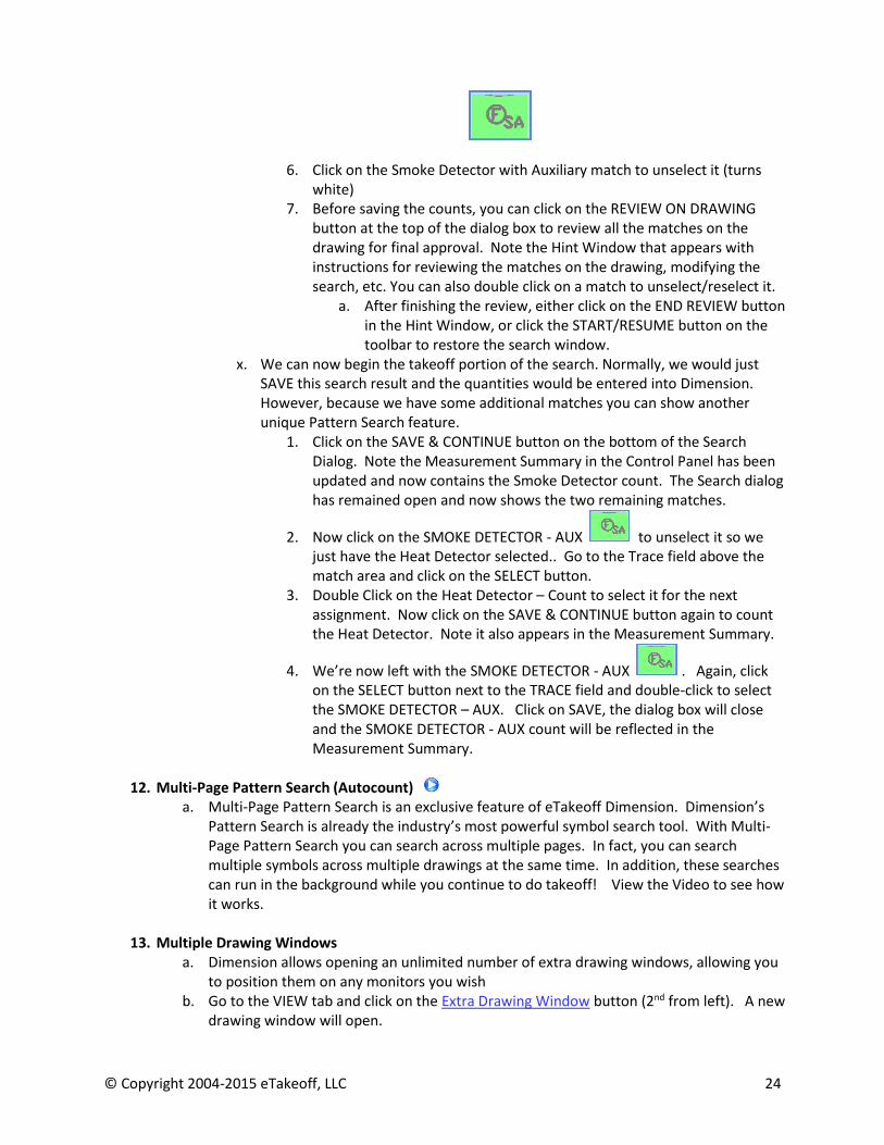
6. Click on the Smoke Detector with Auxiliary match to unselect it (turns white)
7. Before saving the counts, you can click on the REVIEW ON DRAWING button at the top of the dialog box to review all the matches on the drawing for final approval. Note the Hint Window that appears with instructions for reviewing the matches on the drawing, modifying the search, etc. You can also double click on a match to unselect/reselect it.
a. After finishing the review, either click on the END REVIEW button in the Hint Window, or click the START/RESUME button on the toolbar to restore the search window.
x. We can now begin the takeoff portion of the search. Normally, we would just SAVE this search result and the quantities would be entered into Dimension. However, because we have some additional matches you can show another unique Pattern Search feature.
1. Click on the SAVE & CONTINUE button on the bottom of the Search Dialog. Note the Measurement Summary in the Control Panel has been updated and now contains the Smoke Detector count. The Search dialog has remained open and now shows the two remaining matches.
2. Now click on the SMOKE DETECTOR - AUX to unselect it so we just have the Heat Detector selected.. Go to the Trace field above the match area and click on the SELECT button.
3. Double Click on the Heat Detector – Count to select it for the next assignment. Now click on the SAVE & CONTINUE button again to count the Heat Detector. Note it also appears in the Measurement Summary.
4. We’re now left with the SMOKE DETECTOR - AUX . Again, click on the SELECT button next to the TRACE field and double-click to select the SMOKE DETECTOR – AUX. Click on SAVE, the dialog box will close and the SMOKE DETECTOR - AUX count will be reflected in the Measurement Summary.
12. Multi-Page Pattern Search (Autocount) a. Multi-Page Pattern Search is an exclusive feature of eTakeoff Dimension. Dimension’s
Pattern Search is already the industry’s most powerful symbol search tool. With Multi-Page Pattern Search you can search across multiple pages. In fact, you can search multiple symbols across multiple drawings at the same time. In addition, these searches can run in the background while you continue to do takeoff! View the Video to see how it works.
13. Multiple Drawing Windows
a. Dimension allows opening an unlimited number of extra drawing windows, allowing you to position them on any monitors you wish
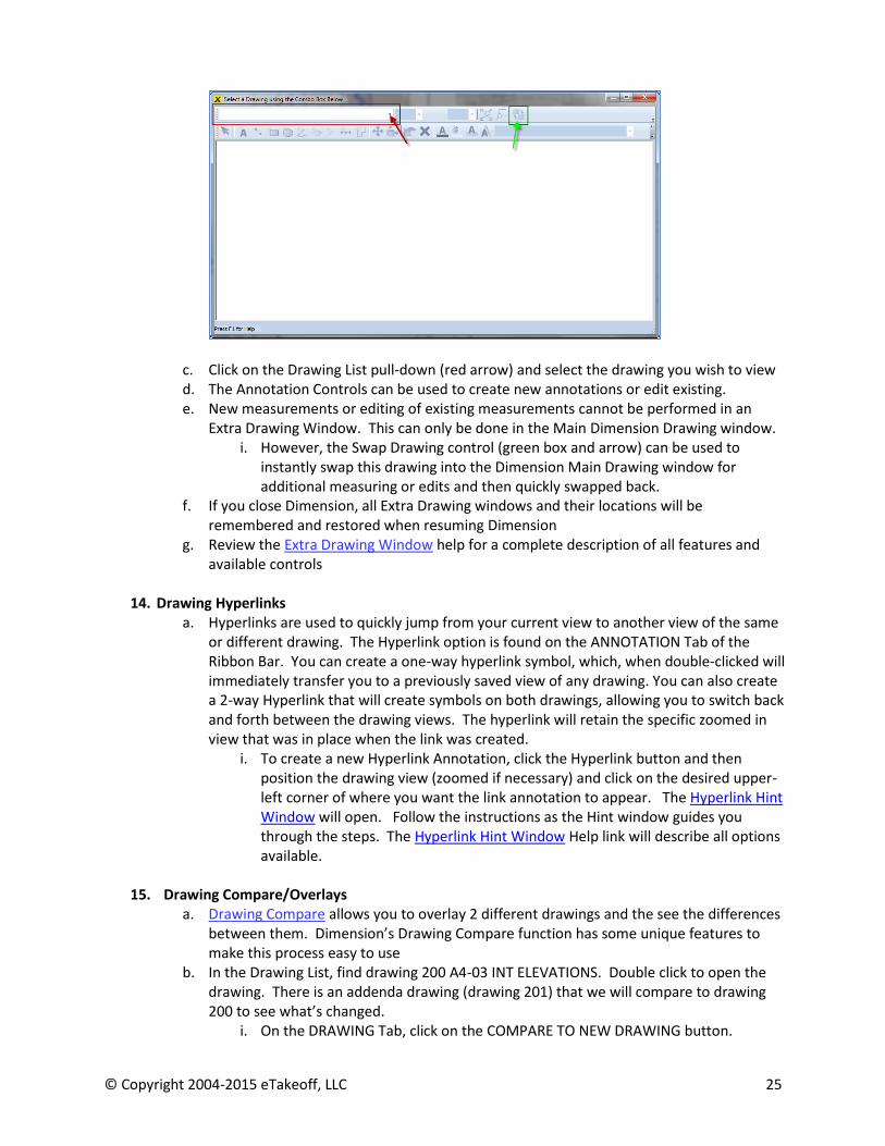
b. Go to the VIEW tab and click on the Extra Drawing Window button (2nd from left). A new drawing window will open.
© Copyright 2004-2015 eTakeoff, LLC 25
c. Click on the Drawing List pull-down (red arrow) and select the drawing you wish to view d. The Annotation Controls can be used to create new annotations or edit existing. e. New measurements or editing of existing measurements cannot be performed in an
Extra Drawing Window. This can only be done in the Main Dimension Drawing window. i. However, the Swap Drawing control (green box and arrow) can be used to
instantly swap this drawing into the Dimension Main Drawing window for additional measuring or edits and then quickly swapped back.
f. If you close Dimension, all Extra Drawing windows and their locations will be remembered and restored when resuming Dimension
g. Review the Extra Drawing Window help for a complete description of all features and available controls
14. Drawing Hyperlinks
a. Hyperlinks are used to quickly jump from your current view to another view of the same or different drawing. The Hyperlink option is found on the ANNOTATION Tab of the Ribbon Bar. You can create a one-way hyperlink symbol, which, when double-clicked will immediately transfer you to a previously saved view of any drawing. You can also create a 2-way Hyperlink that will create symbols on both drawings, allowing you to switch back and forth between the drawing views. The hyperlink will retain the specific zoomed in view that was in place when the link was created.
i. To create a new Hyperlink Annotation, click the Hyperlink button and then position the drawing view (zoomed if necessary) and click on the desired upper-left corner of where you want the link annotation to appear. The Hyperlink Hint Window will open. Follow the instructions as the Hint window guides you through the steps. The Hyperlink Hint Window Help link will describe all options available.
15. Drawing Compare/Overlays
a. Drawing Compare allows you to overlay 2 different drawings and the see the differences between them. Dimension’s Drawing Compare function has some unique features to make this process easy to use
b. In the Drawing List, find drawing 200 A4-03 INT ELEVATIONS. Double click to open the drawing. There is an addenda drawing (drawing 201) that we will compare to drawing 200 to see what’s changed.
i. On the DRAWING Tab, click on the COMPARE TO NEW DRAWING button.

© Copyright 2004-2015 eTakeoff, LLC 26
ii. The Drawing Comparison dialog will open. You can compare as many drawings as you like to the original selection. If you had already selected other drawings to compare, they would be listed here for you to quickly select another comparison.
1. Click on the ADD button to select the drawing we want to compare. iii. The Drawing Comparison Properties window will open. As you review this
window you will see that you can compare drawings from different projects or even drawing files that are not in a Dimension Project.
1. For our example, click on the Drawing pull-down (see image below) and select the Drawing titled 201 A403 INTERIOR ELEV – ADDENDA 1
2. Next, we need to align the drawings. In many cases, the drawings will need no alignment, but frequently they will be offset or twisted during the scanning process.
a. Click the ALIGN button at the bottom of the dialog iv. Dimension will overlay both drawings and the Drawing Comparison Alignment
Tool will open. Zoom into the drawing so you can clearly see Elevation A (to the right of the elevation with the Blue Detail Scale lines around it). Position the Alignment tool so it is easily available.
1. The OLD drawing will be RED. The NEW drawing will be BLUE. If a drawing is perfectly aligned, then all drawing elements that are the same on both drawings will be black. The Alignment Tool is used to align both drawings so that only the differences appear (red = old, blue = new)
2. The 2 drawings in our example are computer generated and of high quality, so they were already perfectly aligned. This will not always be the case, so let’s stop for a second and study the Alignment Tool a bit to get an understanding of how you can use it

© Copyright 2004-2015 eTakeoff, LLC 27
3. The Alignment Tool can be used in a variety of ways
a. If you are using a multi-page drawing, you can verify that you have the right page, or select another
b. You can do major re-orientation (90,180 or 270 degrees) of the new drawing
c. If the drawings are of different sizes, scales or resolution, you can resize the new drawing by using:
i. Auto-Scale - If the drawing scales have already been set for both drawings, you use the Auto-Scale button to automatically resize the new drawing to the old drawing. You may still need to do the low-level alignment described below
ii. 2 Point Alignment – If Auto-Scale is unavailable use 2-point alignment to associate 2 points in the old drawing with 2 points in the new drawing. See the Drawing Compare Help for a full description of how to use this feature
d. Last, you use the Alignment arrows to do a low-level alignment of the new drawing
© Copyright 2004-2015 eTakeoff, LLC 28
i. The arrows allow very fine alignments either up, down or rotated (skewed)
1. It is generally suggested to fix rotation alignments first
2. If you hold a button down it will repeat until released
3. You can use any combination of the CTRL, SHIFT or ALT keys to make the movements larger. Holding one key will make movements 4x larger, 2 keys 16x and all 3 keys 64x.
e. Note that you can also use the mouse to align the new drawing by holding the left button down and dragging it. Small movements may be difficult when using the mouse
f. Again, see the Drawing Compare Help for a full explanation of these features
4. Although our drawings were already aligned, you can experiment a bit by clicking on the low-level alignment arrows to see how misaligned drawings look. Be careful not to get too far out of alignment. If you get wild and can’t get the drawings realigned, simply cancel and restart the Drawing Compare Function
v. Okay…back to the Comparison. Our drawings are perfectly aligned, so click on the OK button to close the alignment tool
c. We now see the new drawing overlaid on the old. You can easily see the differences in the two drawings: Red = OLD Blue = NEW
d. Let’s pan and zoom into Elevation A. e. Because of all the blue and red lines in close proximity, it sometimes becomes difficult to
get a good overview of the changes. Dimension has a unique feature that makes it easier to work with drawings in Comparison mode.
i. Go to any clear area of the drawing and right click the mouse. A Drawing Comparison Context Help window will appear. Position the cursor inside the window and several viewing options will appear to the right. You can experiment with switching between the old and new, etc., but the option we’re most interested in now is EMPHASIZE NEW.
ii. Click on that option and note how the old drawing (Red) recedes slightly and the changes (Blue) can now be more easily seen in context.
f. Now let’s move over to the Typical Room elevation that has our original takeoff. Pan and Zoom into the takeoff. You can see the new changes outlined in blue, and the old drawing in light red lines. In this case, the range top has been rotated and the counter is extended.
g. At this point you are left with deciding how to revise the takeoff. Do you go back to the old drawing and make changes, knowing that the Addenda is now the preferred drawing, or do you redo all your takeoff again on the new drawing. Perhaps you’re faced with doing a bit of both. Dimension has a feature that will allow you to MOVE all the measurements from the old drawing to the new drawing, even converting to a different scale (& Detail Scales) if necessary. You can then perform the necessary takeoff for the new changes and know all your takeoff is now reflected in the current drawing.

© Copyright 2004-2015 eTakeoff, LLC 29
i. While in the Compare Mode, use the Multi-Select button in the HOME Tab (or on the Quick Access Toolbar) to select all the measurements for the Typical Room takeoff by drawing a rectangle around all the measurements.
ii. In any open area of the drawing, right click the mouse again. Find the DRAWING COMPARISON option and note this time that there is another option in the context menu – MOVE/COPY MEASUREMENTS AND ANNOTATIONS.
1. Select that option. The Copy Measurements and Annotations Dialog will open.
2. Click the MOVE option, then click OK. All the measurements will disappear.
3. Now use the Drawing List and open the 201 – ADDENDA 1 drawing by double-clicking it
a. You can now see that Dimension has moved all the original measurements from the old drawing to the new Addenda drawing.
h. Let’s now finish modifying the takeoff to accommodate the drawing changes. i. Pan/Zoom in again to the Typical Room Elevation on the new drawing. Let’s
change the original Carpet measurement to allow for the extended counter. ii. Click on the Carpet Area measurement (Purple – Carpet Type 1) to select the
measurement iii. Click on EDIT POINTS on the HOME Tab OR press the E shortcut key iv. Now click on the original measurement line (where the lower red arrow points)
and drag it to the new counter corner edge (lower green arrow). Then click on the other existing measurement point (upper arrow) and drag it to the right to the corner edge of the counter (upper green arrow). Press the S shortcut key to stop the measurement edit. Your new carpet measurement is complete.
© Copyright 2004-2015 eTakeoff, LLC 30
i. Review the Drawing Compare Help for complete details on all the options available
16. Extensions (Assemblies) (Overview Video) a. Extensions are similar to Assemblies in that they allow you to add additional input and
output parameters to any Trace. Traces will always generate 4 quantities – length, perimeter, area and count. An extension can then be attached to the Trace to ask additional input and then allow you to use the 4 standard quantities and added input variables to calculate completely new quantities.
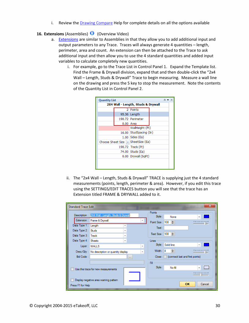
i. For example, go to the Trace List in Control Panel 1. Expand the Template list. Find the Frame & Drywall division, expand that and then double-click the “2x4 Wall – Length, Studs & Drywall” Trace to begin measuring. Measure a wall line on the drawing and press the S key to stop the measurement. Note the contents of the Quantity List in Control Panel 2.
ii. The “2x4 Wall – Length, Studs & Drywall” TRACE is supplying just the 4 standard measurements (points, length, perimeter & area). However, if you edit this trace using the SETTINGS/EDIT TRACES button you will see that the trace has an Extension titled FRAME & DRYWALL added to it.
© Copyright 2004-2015 eTakeoff, LLC 31
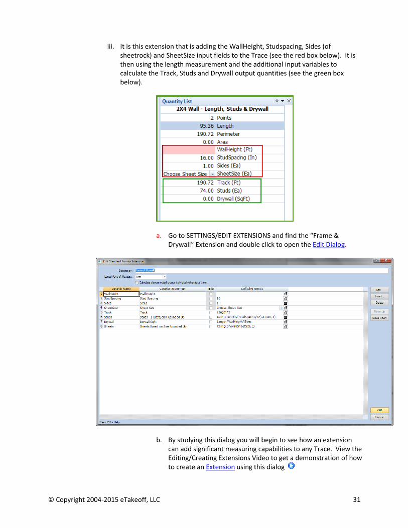
iii. It is this extension that is adding the WallHeight, Studspacing, Sides (of
sheetrock) and SheetSize input fields to the Trace (see the red box below). It is then using the length measurement and the additional input variables to calculate the Track, Studs and Drywall output quantities (see the green box below).
a. Go to SETTINGS/EDIT EXTENSIONS and find the “Frame &
Drywall” Extension and double click to open the Edit Dialog.
b. By studying this dialog you will begin to see how an extension
can add significant measuring capabilities to any Trace. View the Editing/Creating Extensions Video to get a demonstration of how to create an Extension using this dialog
© Copyright 2004-2015 eTakeoff, LLC 32
c. The use of Extensions allows you to create simple or very sophisticated assemblies that significantly expand the power of Dimension! You are limited only by your imagination.
b. Extensions can only be created or edited in the Premier version. However, extensions
created by Premier can be imported into the Advanced version using the IMPORT STANDARDS button on the Settings Tab. You can then perform takeoff in Advanced using the Premier Extensions (assemblies). A variety of Extensions are included in the Trace List in Advanced (e.g. Hip/Valley with Slope).
c. Use the Create/Edit Extension Training video to learn how to create and edit Extensions with formulas/logic/etc.
d. Click on the links below to learn more about the additional Pre-Set Specialty Extensions i. Riser
ii. Joist iii. Roll iv. Grid v. You can customize these for your own use. They are extremely important to
some construction trades. 17. Polar Mode
a. Polar Mode changes the way the cursor behaves while doing measurements. The default behavior of Dimension is Freehand Mode, in which the cursor allows you unrestricted positioning to find the next measurement point on the drawing.
b. When adding points in Polar Mode, the measurement line is forced into horizontal or vertical. Polar Mode is similar to Polar Tracking in AutoCad.
i. This is commonly used to create horizontal or vertical lines or to snap to 15, 30, 45 or 90 degree angles
c. A common setup for Polar Mode is as follows: i. Go to the SETTINGS TAB on the Ribbon Bar
ii. Click on User Preferences Tab on the far left side – The User Preferences window will open
1. Click on the DRAWING tab 2. Find the option DISABLE POLAR MODE WHEN COUNTING and click it to
check the box 3. In the next field below that called POLAR MODE SNAP ANGLES check the
box next to the angles you wish to allow in Polar Mode. 90 degrees is always available
iii. Now Click on the LOOK tab 1. Near the middle you will find the option labeled SHOW RUBBER
BANDING BEFORE MOUSE IS PRESSED. 2. Click to place a check in the box
iv. Click OK to close the Preferences dialog d. You are now ready to use Polar Mode
i. Go to the HOME tab ii. Click on the Polar Mode button in the Takeoff section of the Ribbon Bar
1. Note that Polar Mode will remain on until you press the Polar Mode button again to turn it off
iii. Try a few measurements to experiment. Here are a few hints to consider:
© Copyright 2004-2015 eTakeoff, LLC 33
1. Note that Polar Mode is not on for counts because of the selection we made above
2. If you press the CONTROL key while measuring, it will temporarily disable Polar Mode. This is very useful if Polar Mode works for most aspects of the drawing, but allows you to override the feature for the odd measurement point
a. The CONTROL key option is NECESSARY if you need to measure an ARC or CURVE. When you get to the beginning of the arc, hold the CONTROL key down to “free” the cursor and then click the beginning, center and end of the arc. You can then release the Control key, press the C key to calculate the arc and then continue measuring in Polar Mode.
e. Note that you may prefer the Freehand Mode and only want to invoke Polar Mode for specific measurements. In that case, simply press the CTRL key WHILE MEASURING IN FREEHAND MODE. The cursor will then be in Polar Mode until you release the CTRL key.
18. Bid Codes a. Bid Codes are used to organize measurements by utilizing your own custom Bid Code
structure. This could be a standard CSI code structure or other similar format. You can create your own list of Standard Bid Codes and then assign a Bid Code to each Trace (Trace Properties Window). In the Advanced version, bid codes can be displayed as additional information in the Measurement List, but their real power is utilized in the Premier Version to facilitate the transfer of information to Excel and other estimating applications.
b. Excel integration with Bid Codes is a very powerful tool that lets you automatically assign measurements to a spreadsheet.
i. As you do takeoff, the Measurement List will display all Trace Measurements along with their assigned Bid Code. Using the Copy/Drag Bid Code Links option in the Measurement List you can then export your takeoff data by dragging & dropping it directly onto Excel and automatically summarize all data by your Bid Code structure
1. See Section Excel Integration below for further explanation. c. Bid Codes can also be used to transfer information in a similar manner from the Quantity
Worksheet
19. Quantity Worksheet (Premier version) a. The Quantity Worksheet is a powerful Dimension tool that can be used to create user-
defined estimate output formats. A user-defined Work Breakdown Code lets you create a custom estimate structure for each Worksheet. The Worksheet lets you summarize takeoff measurements by Bid Code from across the project into specific locations on the worksheet to create a standardized estimate format which can then be exported to Excel.
b. The Quantity Worksheet can also be used to create Models with as much sophistication as you desire. A model could be a wall, a room or an entire building - any construction entity that is repetitive in nature. Quantity Worksheets are useful for both detail and conceptual estimates. You can create an unlimited number of Quantity Worksheets (Models)
c. Review the Quantity Worksheet Help for more information

© Copyright 2004-2015 eTakeoff, LLC 34
20. Excel Integration a. Dimension is not compatible with 64 bit Excel for automatic integration purposes. b. At the simplest level, eTakeoff allows you to copy measurements to the Clipboard and
paste directly to any application that supports Copy/Paste. c. However, the Measurement List and/or the Quantity List in the Control Panel are the
primary vehicles for exporting takeoff data to Excel and other applications. You can Drag & Drop specific measurements or Extension variables from the Quantity List, or, from the Measurement List you can drag/drop a single cell, a group of cells, or the entire Measurement List. You can drag/drop this takeoff data into your formatted Excel Spreadsheet and then save that spreadsheet as a Master Template. Then, when starting a new project, Copy/Save the Master Template under the new project name. You can then use the new “empty” spreadsheet as the new project spreadsheet, updating as the project progresses.
d. The Copy/Drag pull-down at the top of the Measurement List or the Drag/Drop Format
Selection icon in the Quantity List Header allows you to select one of three transfer methods before initiating the Drag & Drop from either the Measurement List or directly from the Quantity List in the Control Panel.
i. Copy/Drag Values - When this option is selected, quantity values will be transferred – There is no linked update between the takeoff project and the spreadsheet.
ii. Copy/Drag Measurement Links - When this option is selected, Excel formulas that reference the measurement will be transferred. These links access the measurement value so that if the measurement changes, the spreadsheet value will change when refreshed. You should only use this when you have activated the eTakeoff Excel Add-on and are transferring information to an Excel spreadsheet. Measurement Links also offer the ability to drill down from Excel back into eTakeoff to view the quantity’s associated measurement.
iii. Copy/Drag Bid Code Links –- When this option is selected, Excel formulas that reference the measurement's Bid Code will be transferred. These links total the values of all measurements using that Bid Code. If the measurement using that Bid Code changes, the spreadsheet value will change when refreshed. You should only use this when you have activated the eTakeoff Excel Add-on. Bid Code Links also offers the ability to drill down from Excel back into eTakeoff to view each quantity’s associated measurements
iv. Drill Down Function. If using Measurement Links or Bid Code Links above, you can use the Drill Down function of the Excel Add-on to find the takeoff measurement(s) that support the Qty in the spreadsheet cell. Simply right-click on a cell containing an eTakeoff function and pick "eTakeoff Drill Down" from the context menu. eTakeoff will start (if necessary), open the referenced project
© Copyright 2004-2015 eTakeoff, LLC 35
and drawing or Measurement List and highlight the measurement or item referenced in the formula.
e. Another method of Excel Integration is the Quantity Worksheet. It also has a Copy/Drag pull-down similar to the Measurement List and Quantity List described above, but the Measurement Links option is replaced with Item Links, which is designed to take advantage of the considerable power of Quantity Worksheet Items. Utilizing the Quantity Worksheet for Excel integration enables you to create a static and completely customized Quantity Worksheet that can be linked right into Excel for each new project. The Quantity Worksheet offers the ultimate Excel integration flexibility, but it does require more setup. Review the Quantity Worksheet for details.
21. Multi-User
a. Dimension supports full multi-user concurrent use across the network i. Full record-locking technology
ii. Multiple estimators can work in the same project – Even the same DRAWING – concurrently
22. Concurrent License Manager
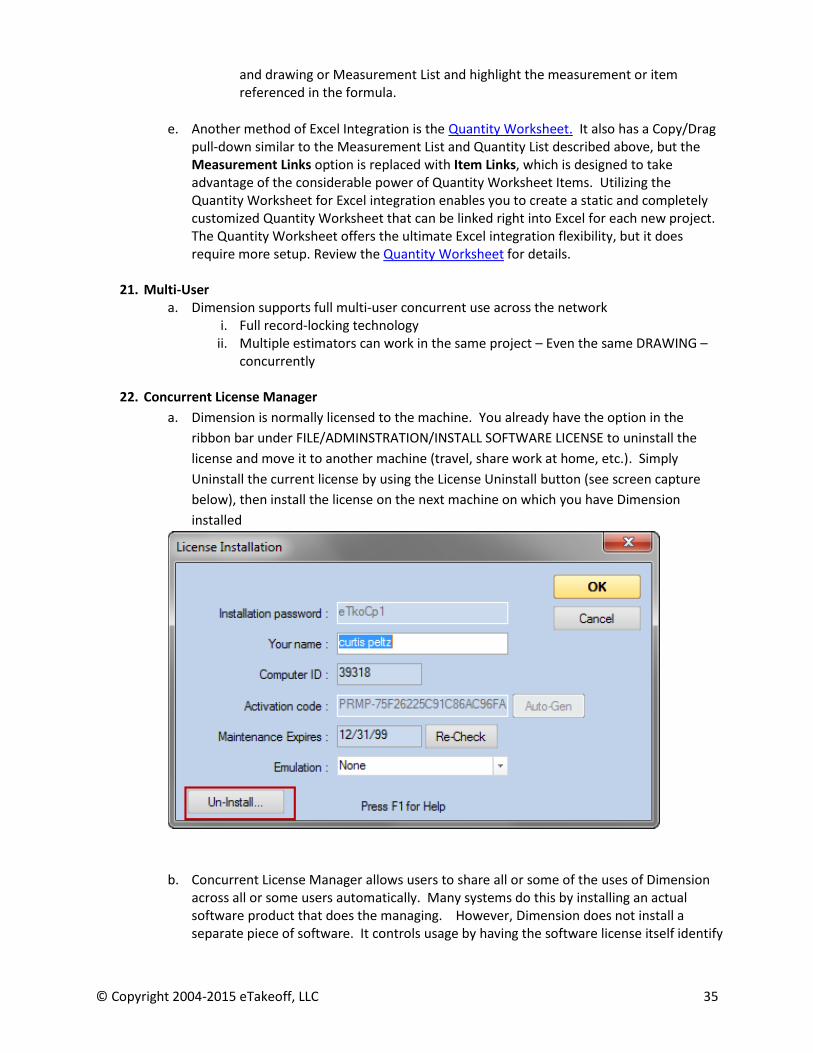
a. Dimension is normally licensed to the machine. You already have the option in the
ribbon bar under FILE/ADMINSTRATION/INSTALL SOFTWARE LICENSE to uninstall the
license and move it to another machine (travel, share work at home, etc.). Simply
Uninstall the current license by using the License Uninstall button (see screen capture
below), then install the license on the next machine on which you have Dimension
installed
b. Concurrent License Manager allows users to share all or some of the uses of Dimension across all or some users automatically. Many systems do this by installing an actual software product that does the managing. However, Dimension does not install a separate piece of software. It controls usage by having the software license itself identify
© Copyright 2004-2015 eTakeoff, LLC 36
whether the use is shared or tied to the machine. This is done when the license is issued by eTakeoff. If the copy is shared, it will check our server to see usage and then communicate to the user if there are no more shares left. This requires internet access (exceptions for web outage are covered…see links below for full explanation).
c. License Manager enables a user to share a copy (or copies) of Dimension. The user can still License Dimension to a specific machine if they want 100% access for that copy while using the License Manager to share other copies. The 2 links below are from the Help system. They will give you a complete explanation of how Concurrent License Manager works.
i. Concurrent Licensing Overview
ii. Concurrent License Window
23. Supported Plan Formats
a. BMP – Windows Bitmap Format
b. CAL – US Department of Defense
c. CPC – Cartesian Perceptual Compression
d. GIF – Graphics Interchange Format
e. IVS – IPIN Viewing System Format
f. JPEG – Joint Photographic Experts Group Interchange Format
g. PDF – Adobe Acrobat – Single and Multi-page
h. PLN – FW Dodge Planroom Graphics Format - legacy
i. PNG – Portable Network Graphics Format
j. TIFF – Tagged Image File Format – Group 3 or 4
24. System Requirements CPU: 2.0 GHz Pentium 4 or greater Memory: 2GB minimum. 4GB or more recommended Disk: 80GB minimum, 200GB recommended Video Card: 32-bit color required. Vista compatible cards highly recommended Monitor: 22 inch or greater recommended. Dual monitors also recommended Mouse: Laser mouse with mouse wheel recommended Dimension is not compatible with 64 bit Excel for automatic integration purposes.