ethernet evb user's guide (pdf) - cdn.intrepidcs.net about the ethernet evb user’s guide and...
TRANSCRIPT

Intrepid Control Systems, Inc.31601 Research Park Drive Madison Heights, MI 48071 USA(ph) +1-586-731-7950 (fax) +1-586-731-2274www.intrepidcs.com www.aeta-rice.com
Ethernet EVBEthernet Experimentation & Evaluation Board
User’s GuideVersion 1.3 - July 22, 2015

Ethernet EVB User’s Guide
i © 2015 Intrepid Control Systems, Inc.Version 1.3 - July 22, 2015
Table of Contents
1 Introduction to the Intrepid Ethernet EVB .................................................................................................11.1 About the Ethernet EVB User’s Guide and Lab Manual ............................................................................11.2 Using Vehicle Spy 3 with the Ethernet EVB ..............................................................................................21.3 Overview of Operation and Essential Features .........................................................................................21.4 Ethernet EVB Block Diagram .....................................................................................................................41.5 IdentificationandDescriptionofEthernetEVBComponents .....................................................................51.6 Hardware and Software Requirements ......................................................................................................9
2 Getting Started with the Intrepid Ethernet EVB .....................................................................................102.1 OpeningtheEEVBPackageandExaminingPackageContents .............................................................102.2 Vehicle Spy 3 Installation ......................................................................................................................... 112.3 Ethernet EVB Hardware Setup ................................................................................................................182.4 VehicleSpy3Configuration .....................................................................................................................212.5 Running Your First Ethernet EVB Demo ..................................................................................................272.6 Licensing Vehicle Spy 3 ...........................................................................................................................34
3 Intrepid Ethernet EVB Support .................................................................................................................373.1 Firmware Updates ....................................................................................................................................373.2 Troubleshooting .......................................................................................................................................393.3 Need More Assistance? ...........................................................................................................................41

Ethernet EVB User’s Guide
1 © 2015 Intrepid Control Systems, Inc.Version 1.3 - July 22, 2015
1 Introduction to the Intrepid Ethernet EVBCongratulationsonpurchasinganIntrepidControlSystems(ICS)EthernetExperimentationand Evaluation Board, known more simply as the Ethernet EVB or just EEVB. This low-cost education and analysis tool is an excellent way to get up to speed with the exciting new vehicle networking technology known as Automotive Ethernet.
The Ethernet EVB contains two fully-functional BroadR-Reach Automotive Ethernet nodes and aspecialactivetestaccesspoint(activetap)thatallowsyoutomonitorEthernetmessagesinreal time. The two nodes can be scripted to implement arbitrary Ethernet functionality, including thesimulationofTCP/IPandAudioVideoBridging(AVB)applications.TheboardalsocontainstwoprogrammableCANnodes,allowingyoutocreateexperimentsthatcombineEthernetandCAN.
1.1 About the Ethernet EVB User’s Guide and Lab Manual
Intrepid has created two documents to help you get the most of your new Ethernet EVB.
Thefirst,whichyouarereadingrightnow,istheEthernet EVB User’s Guide. This reference introduces the EEVB and describes its features, components and functions, helping you better understand the device and how it works. The User’s Guide contains instructions for setting up theboard,installingandconfiguringVehicleSpy3,andensuringthatthetwoareworkingwelltogether.Thisguidewillalsoguideyouthroughaninitialdemosoyoucangetyourfirsttasteof using the EEVB, and be sure that it’s working correctly. Finally, troubleshooting information is provided to help you deal with common issues that may crop up as you begin using your device.
The second resource for the board is the Ethernet EVB Lab Manual. This document contains examples and scenarios that showcase some of the many ways that the Ethernet EVB can be used to demonstrate the operation of Automotive Ethernet. The Lab Manual uses special downloadablescenariosetupfiles—availablefreeontheICSwebsite—andstep-by-stepinstructions to show you how Automotive Ethernet frames are sent and received. It walks youthroughvarioussampleapplicationssuchasanARPRequest/Replyexchange,custom-programmed input and output, sending data using IP messages, and much more.
BesuretoalsovisitIntrepid’sspecialwebpagededicatedspecificallytotheEthernetEVB,which can be found at http://www.intrepidcs.com/ae/eevb/.
Note: To avoid repetition, the Lab Manual assumes that you have already reviewed the User’s Guide and followed the
instructions it contains for setting up the Ethernet EVB board and Vehicle Spy 3 software. For this reason, we recommend reading the User’s Guide before proceeding to the Lab Manual.

Ethernet EVB User’s Guide
2 © 2015 Intrepid Control Systems, Inc.Version 1.3 - July 22, 2015
1.2 Using Vehicle Spy 3 with the Ethernet EVB
A computer without software is just a paperweight, and in a similar way, the Ethernet EVB without software would just be a fancy circuit board with blinking lights. Your EEVB needs apartnertohelpitliveuptoitsfullpotential,whichICSprovidesintheformofitspowerfulVehicle Spy 3monitoringanddiagnosticsoftware(oftenabbreviatedasVSpy).
Vehicle Spy 3 is designed to work hand in hand with the Ethernet EVB. As we go through this guide you will see how VSpy is used to set up example applications, create scripts for the EEVBandprogramitsEthernetnodes,andmonitorEthernettrafficcapturedbytheboard.We’ll also see in much greater detail in the Lab Manual how Vehicle Spy 3 can be used to monitorEthernettrafficonothernetworkinterfaces,allowingyoutoanalyzeframescomingintoaPCfromanysource.
EachEEVBpurchasecomeswithathree-monthlicenseforthe(fully-functional)demoversionof Vehicle Spy 3 Professional. As you go through the User’s Guide and the Lab Manual, youwilllearnthatVehicleSpy3isacomprehensivetoolincorporatingdozensoffunctionsand features to enable analysis, simulation, diagnostics and data acquisition on all common automotive networks.
1.3 Overview of Operation and Essential Features
Let’s start out with a brief discussion of how the Intrepid Ethernet EVB works, and some of its more important features. The description that follows will help you understand better what the board is all about, and how it works with Vehicle Spy 3. This will also set the stage for the detailed descriptions and examples found in the Lab Manual.
Scriptable BroadR-Reach (Automotive Ethernet) Nodes
The heart of the Ethernet EVB is its pair of BroadR-Reach nodes, each of which contains thecomponentsnecessarytofullysimulatetheoperationofanAutomotiveEthernetECU.EachnodeisbasedaroundanARMCortex-M432-bitmicroprocessordesignedbySTMicroelectronics,runningatupto180MHz,whichservesasthe“brain”ofthenode.Itissupported by various other components that allow the node to be programmed and updated, and its status monitored.
TheARMCPUshave2MBofintegratedflashmemoryeach,whichisusedfortwopurposes.First,itimplementsstandardEthernetMediaAccessControl(MAC)functionality,permittingthe node to behave as a standard Ethernet device using a Broadcom BroadR-Reach chip atthephysicallayer.Second,thisflashmemoryholdsthecustomprogramsthatimplementexamples and demos, such as the one we will use later in this guide, and the others described in the Lab Manual.
Tousethenodes,theirdesiredoperationisfirstprogrammedusingthepowerfulscriptingfeatures found in Vehicle Spy 3. Each script is then compiled into a special module known as

Ethernet EVB User’s Guide
3 © 2015 Intrepid Control Systems, Inc.Version 1.3 - July 22, 2015
a CoreMini,whichisprogrammed(flashed,downloaded)intotheARMchipusingVSpy.Thescript then runs on the node, implementing the feature desired by the example or application.
Note: The EEVB is normally shown with its USB connection at thetopandCANconnectorsonthebottom.Inthisorientation,
the BroadR-Reach node on the left is called Node A, while the right-hand node is Node B.
Programmable Input and Output Devices
Each BroadR-Reach node includes four special input and output components:
• Pushbutton: A small black button is located just above each ARM chip that can be used as a simple binary input, such as to start or stop a particular function, or signal the generation of a message or event. It is read as a 0 value by the node in its default state, ora1whilethebuttonisdepressed.(EachnodealsohasasecondpushbuttonusedtoresetitsCPU.)
• Potentiometer:Formoreflexibleinput,apotentiometer(variableresistor)isprovidedwithin both nodes. Each appears as a small black dial that can be turned using your fingers,generatinga12-bitinputcorrespondingtodecimalvaluesfrom0to4,095.
• Output LEDs: Each node has a pair of LED indicators that, by default, indicate the state ofthenode’sCPU.However,bothcanalsobeturnedonoroffunderprogramcontroltoindicate status or communicate other information.
These components can be used singly or in combination. For example, later we will see a sampletestsetupthatusesthepotentiometersettingofeachnodetocontroltheflashrateofone of its output LEDs, while also displaying the status of its pushbutton.
BroadR-Reach Active TAP for Ethernet Monitoring
UnlikemoretraditionalautomotivenetworkssuchasCAN,itisnotpossibletodirectlyconnecta probe to an Automotive Ethernet cable to monitor its activity. To implement this essential function, the Ethernet EVB includes a special chip from XMOS that serves as an active tap.
TheXMOSchipcapturesalltrafficthatissentorreceivedbytheBroadR-ReachPHYchipofNode0,placingeachframeinaspecial“wrapper”toallowittoberetransmittedinitsentirety.This allows even frames with errors to be preserved for analysis. These are then sent to an integratedstandard10/100EthernetPHY,andfromtheretoanEthernet/USBhub,whichforwardstheframestoyourPCusingtheEEVB’sUSB2.0connection.Theseframescanthenbe displayed and processed in Vehicle Spy 3.

Ethernet EVB User’s Guide
4 © 2015 Intrepid Control Systems, Inc.Version 1.3 - July 22, 2015
Audio Support Hardware
Eachnodeincludesastandard4-contactheadsetjack,whichisconnectedtoaCirrusaudiocodecandamicrophoneamplifier,componentsthatareinturnlinkedtotheARMCPU.Thispermitssingle-channel(mono)audiotobeinputtoeachnode,aswellasdual-channel(stereo)audio output. These components can be used to aid in creating simulations and applications involving AVB, one of the most common early applications of Automotive Ethernet.
Scriptable CAN Nodes
TheboardcontainsapairofCANnodes,eachwithitsownstandardDE-9connector.Thesenodescanbescripted,justliketheEthernetnodes.AbridgeisprovidedtoallowtheCANnodes to be linked together.
Note: By convention, with the board in its standard orientation (USBconnectoratthetop)theCANnodebottomleftisNode
A, while the one bottom right is Node B.
1.4 Ethernet EVB Block Diagram
Figure 1 shows a basic block diagram of the Ethernet EVB, illustrating its most important components. The blocks are coded according to their basic function: red and green for BroadR-Reach Node A and Node B respectively; blue for Ethernet monitoring and interfacinghardware;andmagentafortheCANcircuitry.Thediagramhasbeenorganizedtoapproximatelymatchtheconfigurationoftheactualcomponentsontheboard,thoughitisnotexact(norisittoscale).

Ethernet EVB User’s Guide
5 © 2015 Intrepid Control Systems, Inc.Version 1.3 - July 22, 2015
Node AARM CPU
Node BARM CPU
USB 2.0Connector
Ethernet /USB 2.0
Hub
Node ABroadR Mini50
Connector
Node B BroadR Mini50
Connector
10/100 Ethernet
PHY
Node ABroadR
PHY
Node B BroadR
PHY
CANNode A
Transceiver
CANNode B
Transceiver
XMOSBroadR-Reach
Active TAP
CANNode A
Connector
CANNode B
Connector
CAN Bridge
Node A Audio Jack
Node B Audio Jack
Node A Audio Codec
Node A Mic
Amp
Node B Audio Codec
Node B Mic
Amp
Node A Button
Node A LED 1
Node A Pot
Node B LED 1
Node B Button
Node B Pot
XMOS Flash
Node A LED 2
Node B LED 2
Figure 1: Ethernet EVB Block Diagram. This illustration lays out the major functional elements of the Intrepid Ethernet EVB.
1.5 Identification and Description of Ethernet EVB Components
In Figure 2youwillfindaphotographoftheEthernetEVBwithnumericlabelssuperimposedupon, or pointing to, each of its essential components. You may notice that the labels use the same four colors as the block diagram in Figure 1, which naturally is not a coincidence! Each of the four areas of the board also has its components numbered in a different sequence to make it easier to identify and keep track of each part. We make reference to this diagram later inthisguide,aswellasintheLabManual,whenitisnecessarytoidentifyspecificpartsforvarious reasons.
Belowwewilllistandbrieflydescribeeachofthecomponentsinthefigurebyfunctionalarea.

Ethernet EVB User’s Guide
6 © 2015 Intrepid Control Systems, Inc.Version 1.3 - July 22, 2015
8A7
Figure 2: Ethernet EVB Component Identification. This illustration shows the Ethernet EVB with all major components labeledforeasyidentificationandreference.
BroadR-Reach Node A and Node B
Thesecomponentsarelabeledwithredandgreennumbers,startingwith“A”forNodeAandwith“B”forNode1.Sincethenodeshavethesamebasiccomponents,theyhavebeennumbered so that the digits following the letter represent the identical device on each node. The parts are as follows:
• A01/B01: Molex Mini50 BroadR-Reach connectors. These can be used to link the nodes to each other using the supplied cable, or to connect them to other BroadR-Reachnodes(suchasswitchports).
• A02/B02:BootstrapblocksfortheARMCPUs(ICSuseonly).
• A03/B03:BroadcomBroadR-ReachPhysicalLayer(PHY)chips.

Ethernet EVB User’s Guide
7 © 2015 Intrepid Control Systems, Inc.Version 1.3 - July 22, 2015
• A04/B04:BroadR-ReachPHYlink/activityLEDs.EachindicatorflasheswhenitscorrespondingPHYisconnectedtoanotherBroadR-Reachdevice;bothwillflashundernormal operation when the two nodes are linked to each other using the supplied cable.
• A05/B05:Audioinput/outputjacks.
• A06/B06:CirrusLogicaudiocodecsforstereoaudiooutput.
• A07/B07:Microphoneamplifierchipsformonoaudioinput.
• A08/B08:CPUdebugports(ICSuseonly).
• A09/B09: Pushbutton inputs.
• A10/B10:CoreMiniactivity/outputLEDs(LED1).BydefaulttheseLEDsflash5timespersecondwhenaCoreMiniprogramisrunningonthecorrespondingnode,buttheycan also be turned on and off under program control.
• A11/B11:ARMCortex-M4CPUs.
• A12/B12: Potentiometer inputs.
• A13/B13:ARMCPUresetbuttons.
• A14/B14:CPUactivity/outputLEDs(LED2).BydefaulttheseLEDsflash5timespersecond when noCoreMiniisrunningontheassociatednode,butthesecanalsobescript-controlled.
• A15/B15:BootstrapblocksfortheARMCPUs(ICSuseonly).
• A16/B16:JTAGdebugheadersfortheARMCPUs(ICSuseonly).
Ethernet Monitoring and USB Interface
These components, tagged with blue labels, implement the EEVB’s Ethernet functionality, includingtheBroadR-Reachactivetap,Ethernet/USBhubandUSBinterface:
• E01:EthernetspeedLED(HubtoPC).Whenon,indicates100Mb/scommunicationovertheUSBlinktothePC;whenoff,speedis10Mb/s.Normallyon.
• E02:Ethernetlink/activityLED(HubtoPC).Whenon,alinkisestablishedbetweentheEthernet/USBhubandthePC.Flashingindicatesthetransmissionofframesoverthelink.
• E03:Ethernetfull-duplexLED(HubtoPC).Thiswillnormallybeon,asfull-duplexcommunication is the default.
• E04:Ethernetfull-duplexLED(10/100PHYtoHub).Again,normallythiswillremainlit.
• E05:EthernetactivityLED(10/100PHYtoHub).FlasheswhentrafficispassedbetweentheEthernet10/100PHYandtheintegratedEthernet/USBhub.

Ethernet EVB User’s Guide
8 © 2015 Intrepid Control Systems, Inc.Version 1.3 - July 22, 2015
• E06:EthernetlinkLED(10/100PHYtoHub).NormallyontoindicatealinkbetweentheEthernet PHY and hub.
• E07:EthernetspeedLED(10/100PHYtoHub).Whenlit(normal),indicates100Mb/soperationbetweentheEthernetPHYandhub;whendark,10Mb/s.
• E08: Mini-USB jack, used both to supply power to the EEVB and to send Ethernet framestoandfromthePCoverUSB.
• E09:Ethernet/USBhub.Connectsthe10/100PHYandthePC,translatingbetweenEthernet and USB formats as needed. The hub is also connected directly to the two CPUstoallowCoreMiniprogramstobetransferredtothem.
• E10: Transformer for Ethernet PHY.
• E11: XMOS Active tap. Monitors Node 0 BroadR-Reach PHY and sends frames to the PCthroughthehub.
• E12:BootflashmemoryfortheXMOSchip.
• E13:10/100EthernetPHY.
• E14:Oscillatorforthe10/100PHY.
• E15:Powersupplyforthe10/100PHY.
• E16:JTAGdebugheaderfortheXMOSchip(ICSuseonly).
CAN Node A and Node B
Along the bottom of the Ethernet EVB circuit board are several components that implement its twoCANnodes,whichhavemagentalabelsinFigure 2:
• C01:CANNodeADE-9connector.
• C02:CANNodeAtransceiver.ThischipimplementstheCANnetworkfunctionalityforNode A.
• C03:CANNodeAterminationselectionblock.
• C04:CANbridge.ThisjumperblockcanbeusedtobridgeCANNodeAandCANNodeB to each other.
• C05:CANNodeBterminationselectionblock.
• C06:CANNodeBtransceiver.
• C07:CANNodeBDE-9connector.

Ethernet EVB User’s Guide
9 © 2015 Intrepid Control Systems, Inc.Version 1.3 - July 22, 2015
1.6 Hardware and Software Requirements
The EEVB’s hardware and software prerequisites are based on two factors: the resources needed to support the board itself, and those necessary for running Vehicle Spy 3.
EEVB Hardware Requirements
TheEEVBrequirestwoUSB2.0(or3.0)portsonthehostcomputertowhichitisattached.As we’ll see shortly, the board uses a special USB cable with two standard connectors: one provides power and facilitates data transmission from the board to the host machine, while the second provides supplemental power to run the many components on the board.
If necessary, the EEVB can be connected to a USB 2.0 hub that is in turn plugged into the computer on which VSpy runs. Depending on the amount of electrical energy provided by the computer’sownUSBports,apoweredhub(onewithitsownpowersupply)mayberequired.
Vehicle Spy 3 System Requirements
VehicleSpy3isdesignedtorunonmostmodernPCcompatiblecomputersandmodernversions of Microsoft Windows. The current minimum requirements are as follows:
• Operating System:MicrosoftWindowsXP(SP3),WindowsVista(Pre-SP,SP1,orSP2),Windows7(Pre-SPorSP1),Windows8,orWindows8.1.
• System Memory: 512 MB.
• Display Resolution: 1024x768.
Vehicle Spy 3 will run on both 32-bit and 64-bit versions of Windows. However, Windows RT is notsupported(asitdoesnotrunonPCs).
For an optimal experience, Intrepid recommends at least the following:
• Operating System:WindowsXP(SP3),WindowsVista(Pre-SP,SP1,orSP2),Windows7(Pre-SPorSP1),Windows8,orWindows8.1.
• Processor:IntelorAMDx86(32-bit)orx86-64(64-bit)CPU,2GHzorhigher.
• System Memory: 2 GB.
• Display Resolution: 1280x1024.
As a 32-bit application, Vehicle Spy 3 cannot use of more than 2 GB of memory. However, additionalmemoryallowsgreaterflexibilitytoopenmultipleinstancesanddealwithlargerfiles.
Displayresolutionisalsoimportant,asmorescreen“realestate”willallowyoutoseealarger quantity of messages, graphs and other information on the screen at once. The EEVB documentation is based on the minimum of 1024x768, and the screenshots in the User’s Guide and Lab Manual were taken at this resolution. However, a larger screen will improve your user experience.

Ethernet EVB User’s Guide
10 © 2015 Intrepid Control Systems, Inc.Version 1.3 - July 22, 2015
2 Getting Started with the Intrepid Ethernet EVBNow that we have covered the basics of the Intrepid Ethernet EVB and how it functions, we’re ready to put your new board to work. In this chapter we’ll review the contents of the EEVB package and get your hardware and software up and running.
2.1 Opening the EEVB Package and Examining Package Contents
The Ethernet EVB ships in a small, convenient box that contains all the hardware you need to set up your Automotive Ethernet experimentation network. You can also use the box to easily transportthesetuptoanothercomputerorlocation,lettingyoutakeyournetwork“ontheroad”whenever required.
Please open your EEVB box now and remove the components contained within it. Each packagecontainsthefollowingphysicalitems(asshowninFigure 3):
• Ethernet EVB Board: The actual EEVB circuit board, which contains all of the electronic components required to create your Ethernet network.
• Software and Documentation Disc: A disc containing a demo version of Vehicle Spy 3, a license for the EEVB, and electronic copies of the User’s Guide and Lab Manual.
• “Two-Headed” USB Cable: A special USB cable with a mini-USB connector on one end to attach to the EEVB, and a pair of standard USB connectors on the other to link theboardtoaPC.
• BroadR-Reach Cable: A single twisted pair cable with Molex Mini50 plugs on each end. This cable allows you to link the EEVB’s two BroadR-Reach nodes to each other so they can communicate directly.
If any of these parts is missing from your Ethernet EVB package, or if they appear to be damagedinsomeway,pleasecontactIntrepidControlSystemsimmediatelyforassistanceinobtaining replacement hardware.
AlongwithyourEEVByouwillalsoreceiveacopyofICS’sindustry-leadingbook,Automotive Ethernet - The Definitive Guide, which will be packaged separately. This book provides comprehensive information on Automotive Ethernet and the protocols used in the Lab Manual, where it is discussed further.

Ethernet EVB User’s Guide
11 © 2015 Intrepid Control Systems, Inc.Version 1.3 - July 22, 2015
Figure 3: Ethernet EVB Package Contents. Your Ethernet EVB package contains the EVB itself, a special USB cable for poweringtheboardandconnectingittoyourPC,adual-plugBroadR-Reachcable,andasoftwareanddocumentationdisc.Acopy of Automotive Ethernet - The Definitive Guide is also included, but packaged separately.
2.2 Vehicle Spy 3 Installation
It is possible to install your hardware and software in either order. However, the EEVB requires special drivers that are installed automatically along with Vehicle Spy 3. For this reason, we recommendinstallingVSpybeforeconnectingtheEEVBhardwaretoyourPC.
Vehicle Spy 3 is packaged with an automated installer, which will do most of the work for you. Simply follow the instructions below to set up the program on your computer.
1. Load the Software and Documentation Disc: Put the disc that came with your EEVB intotheopticaldriveofyourcomputer.Afewsecondslater,theICSsoftwareinstallationmenu should automatically appear on your computer screen, as shown in Figure 4.
Note: On some computers this window may not appear on its own. If this occurs, start Windows Explorer, navigate to the
disc’s letter under Computer, and then double-click the fileicsSetup.exe to open the menu.

Ethernet EVB User’s Guide
12 © 2015 Intrepid Control Systems, Inc.Version 1.3 - July 22, 2015
Figure 4: ICS Software Install Menu.
From this menu you can start installing Vehicle Spy 3, access electronic copies of the EEVB User’s Guide and Lab Manual, or go to the support area on the Intrepid website.
2. Start Vehicle Spy 3 Installation:Click .
3. Select Language:Chooseyourpreferredlanguageandthenclick to proceed. (FortheremainderofthemanualwewillassumethatEnglishhasbeenused.)
TheVehicleSpy3setupwizardwillnowstart,displayingawelcomescreenasshowninFigure 5.
Figure 5: Vehicle Spy 3 Setup Wizard Welcome Screen.

Ethernet EVB User’s Guide
13 © 2015 Intrepid Control Systems, Inc.Version 1.3 - July 22, 2015
4. Start Vehicle Spy 3 Setup Wizard:Click tostartthesetupwizard.
5. Review and Accept License Agreement: Review the license agreement, and assuming its terms are acceptable, select , then click (Figure 6).
Figure 6: Vehicle Spy 3 License Agreement.
6. Select Installation Type: We are doing a new installation so simply click to continue.
7. Select Destination Location:ChoosewhereyouwanttoinstallVehicleSpy3(Figure 7).Wenormallyrecommendusingthedefaultlocation.Click .
Figure 7: Choosing the Destination Location.

Ethernet EVB User’s Guide
14 © 2015 Intrepid Control Systems, Inc.Version 1.3 - July 22, 2015
8. Select Data Directory Location: Next, choose where you want Vehicle Spy 3tostoreitsdatafiles.Werecommendstickingwiththeprovideddefault,C:\IntrepidCS\Vehicle Spy 3(Figure 8).Click to continue.
Figure 8: Selecting the Data Directory Location.
9. Select Start Menu Folder:ChoosewhereyouwantyourWindowsshortcutsforVehicleSpy3toreside.Again,thedefaultsaregenerallyfinehere,thoughyoucanchangethemifyouwish.Click to proceed.
10. Select Additional Tasks: The one option here is to create a desktop icon for Vehicle Spy 3, which is selected by default. Uncheck the box if you do not wish to have this icon created, then click .
YouhavenowprovidedalloftheinformationthewizardneedstoinstallVehicleSpy3.Yourselected options will be displayed in a review box, as shown in Figure 9.
Figure 9: Installation Options Review.

Ethernet EVB User’s Guide
15 © 2015 Intrepid Control Systems, Inc.Version 1.3 - July 22, 2015
11. Review Installation Options and Begin Installation: Ensure that the options you have chosen are correct, and then click .
ThewizardwillnowbegininstallingVehicleSpy3.Awindowwillappearshowingyoutheprogressoftheinstallation(Figure 10).
Figure 10: Installing Vehicle Spy 3.
Aftercompletinginstallationofthesoftwareitself,thewizardwillautomaticallyinstallvariousdriversrequiredbyVehicleSpy3andtheEEVB.ThefirstinstallwillbeguidedbytheVCPDriver Installer.
12. Install VCP Drivers:Click tobegininstallingthefirstsetofdrivers.Thiswillusually take only a few seconds, and when completed, a message will appear like the one in Figure 11.Click to complete this initial driver installation process.
Figure 11: VCP Driver Installation Complete.

Ethernet EVB User’s Guide
16 © 2015 Intrepid Control Systems, Inc.Version 1.3 - July 22, 2015
Next,supportfilesforMicrosoftVisualC++2010and2005willbeinstalled.Thishappensautomaticallywithoutuserintervention.Manysystemsalreadyhavethesefilesinstalled,andifso, a message may appear telling you this; just hit to continue.
The WinPcap installer will start next. This is a special support program that allows Ethernet trafficonaPCtobecapturedanddisplayedbyVehicleSpy3.Youwillseeawindowsimilartothe one shown in Figure 12.
Figure 12: WinPcap setup wizard.
13. Install WinPcap:Click to start the installation process. Review the WinPcap license agreement and click if you are willing to abide by its terms. Leave the box on the next screen checked so that WinPcap starts automatically, and click . After a few seconds a message will appear saying that the installation is complete; click
to exit this installer.
ThesetupwizardwillnowinstallSMSCLAN9500devicedrivers,whichareusedfortheUSBdataconnectionbetweentheEEVBandyourPC.Thisonlytakesafewsecondsandrequiresno user intervention; you may see a message on the screen like Figure 13.
Figure 13: SMSC LAN9500 device driver installation.
AnotherICSdriverinstallerdialogboxwillappearnext,similartothefirstone.
14. Install ICS Port Drivers:Click tobegininstallingtheICSportdrivers.
At this point you may receive a prompt from Windows like the one shown in Figure 14. If you do, please click toauthorizedriverinstallation.

Ethernet EVB User’s Guide
17 © 2015 Intrepid Control Systems, Inc.Version 1.3 - July 22, 2015
Figure 14: Windows Security Dialog Box.
Once installation begins, it will take only a few seconds, and when completed, a message will appear like the one in Figure 15.
15. Complete Port Driver Installation:Click to exit this part of the install.
Figure 15: Port Driver Installation Complete.
TheinstallerwillnextsetuptheCrypKeyserver,whichlicensesthedemoversionofVSpy.Youdon’tneedtodoanythingexceptclosethewindowthatappearswhenthisisdone(Figure 16).
Figure 16: CrypKey Installation Complete.
16. Close CrypKey Setup Window:Click when the message appears saying that CrypKeysetupiscomplete.
You will now see a window similar to Figure 17, indicating that the setup process is complete.
Ethernet EVB User’s Guide
18 © 2015 Intrepid Control Systems, Inc.Version 1.3 - July 22, 2015
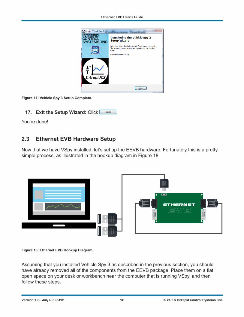
Figure 17: Vehicle Spy 3 Setup Complete.
17. Exit the Setup Wizard:Click .
You’re done!
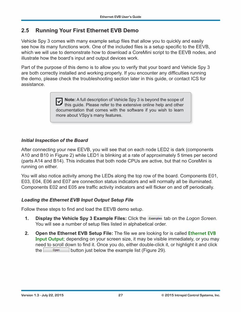
2.3 Ethernet EVB Hardware Setup
Now that we have VSpy installed, let’s set up the EEVB hardware. Fortunately this is a pretty simple process, as illustrated in the hookup diagram in Figure 18.
Figure 18: Ethernet EVB Hookup Diagram.
Assuming that you installed Vehicle Spy 3 as described in the previous section, you should havealreadyremovedallofthecomponentsfromtheEEVBpackage.Placethemonaflat,open space on your desk or workbench near the computer that is running VSpy, and then follow these steps.

Ethernet EVB User’s Guide
19 © 2015 Intrepid Control Systems, Inc.Version 1.3 - July 22, 2015
1. Remove Board from Anti-Static Wrapping: Take the EEVB board out of its protective anti-static bubble wrap and place it on the surface you have chosen.
Warning: The EEVB is a bare circuit board with exposed contacts on the bottom. Do not use it on a conductive surface,
ordamagetotheboardand/orsurfacemayoccur.Wealsodonotrecommend operating it on top of its anti-static packaging.
2. Connect USB Cable to PC or USB Hub: Attach the two standard USB connectors on oneendofthespecialUSBcabletothePC.Youcanconnectthemeitherdirectlytoapair of USB ports on the machine, or use a hub as shown in Figure 19.
Figure 19: Connecting the USB Cable to a USB Hub.Plugthe“two-headed”USBcableintoapairofUSBportsonyourPCor a USB hub.

Ethernet EVB User’s Guide
20 © 2015 Intrepid Control Systems, Inc.Version 1.3 - July 22, 2015
3. Connect USB Cable to EEVB:Connectthemini-USBconnectorontheotherendofthe cable to the Ethernet EVB, as shown in Figure 20.
Figure 20: Connecting the USB Cable to the Ethernet EVB. Attach the mini-USB connector to the EEVB’s USB port (component208ontheboardlayoutdiagraminFigure 2).
Upon completing the USB connection to the EEVB, the board will power up, and you should seeseveralofitsindicatorLEDsilluminate,somesolidandsomeflashing.TheboardwillalsoberecognizedinWindows,andifthisisthefirsttimeyouhaveconnectedit,youmayseeamessage saying that device drivers are being installed. You actually installed the necessary driverswhenyouinstalledVehicleSpy3,sothisisjustWindowsconfiguringthosedriversforuse. When complete, you should see a message similar to that shown in Figure 21.
Figure 21: Windows Device Driver Installation Message.Notethatthenumbernextto“COM”mayvary.

Ethernet EVB User’s Guide
21 © 2015 Intrepid Control Systems, Inc.Version 1.3 - July 22, 2015
4. Connect BroadR-Reach Cable: Attach one end of the BroadR-Reach cable to each of theMini50jacksontheleftandrightedgesoftheboard(componentsA01andB01)asseen in Figure 22.
Figure 22: Linking the Two BroadR-Reach Nodes. Use the supplied BroadR-Reach cable to connect the two EEVB nodes to each other.
ThefinalstepabovelinksthetwoBroadR-Reachnodessotheycancommunicatewitheachother directly. This is required for certain aspects of the board’s operation; we will make use of this connection in our initial demo later in this guide, and employ it further in the Lab Manual.
Your EEVB is now ready for use. If you experience any issues setting up the hardware, please refertothetroubleshootingguideinChapter3.
2.4 Vehicle Spy 3 Configuration
We now have both Vehicle Spy 3 and the EEVB installed. However, there are a few additional steps that we need to take in order to ensure that the two work together correctly in an Automotive Ethernet environment.

Ethernet EVB User’s Guide
22 © 2015 Intrepid Control Systems, Inc.Version 1.3 - July 22, 2015
Starting Vehicle Spy and Adding a License File
VehicleSpy3requiresahardwarelicensefiletooperate.Oneisincludedonthesoftwareanddocumentation disc that comes with your EEVB; you just need to tell the program where it is.
Follow these steps:
1. Start Vehicle Spy 3: Launch Vehicle Spy 3 from your computer’s start menu: select All Programs►IntrepidCS►Vehicle Spy 3►Vehicle Spy 3. Alternatively, you can click the red car icon on your desktop.
YouwillseeanorangeCrypKeysplashscreenappearforafewseconds;pleaseignorethisfornow.
VehicleSpy3willautomaticallyopenitssetupscreenandpromptyoutoaddalicensefile,asshown in Figure 23.
Figure 23: Vehicle Spy 3 License Area.
2. Add License File:Click .Afileselectiondialogboxappears.Navigatetotherootfolderofthesoftwareanddocumentationdisc,whereyoushouldseea“.lic”file.(Ifoneisnotpresent,pleasecontactIntrepidforassistance.)Selectthefile,thenclick
.

Ethernet EVB User’s Guide
23 © 2015 Intrepid Control Systems, Inc.Version 1.3 - July 22, 2015
Vehicle Spy 3 will display a summary of your license information, similar to the example shown in Figure 24.
Figure 24: Vehicle Spy 3 License Information Display. Naturally, the values shown on your screen will differ from the ones seen here.
3. Close the License Setup Tab:Click to complete adding the license.
You will now be prompted to restart the program.
4. Restart Vehicle Spy 3:Click to close Vehicle Spy 3. Then start it again from the Start Menu or desktop.
Vehicle Spy 3 will now start up in its normal default window, known as the Logon Screen (Figure 25).Youwillseeawhiteboxinthemiddleofthedisplay,abovewhicharethreetabs.The tabisautomaticallypopulatedbyVehicleSpy3withlinkstothesetupfilesyouhavemost recently used, while listsallofthesetupfilesassociatedwiththisdatadirectory.(Sincewejustinstalledtheprogram,bothwillbeempty.)Thefinaltab, , contains samplesetupfilesthatshipwithVSpy,includingonethatwe’lluseshortly.
Near the bottom of the screen you should see a photo of the Ethernet EVB, which tells you immediately that VSpy sees your board. To the right is a list of Vehicle network interfaces, which should show two entries corresponding to the two EEVB nodes.

Ethernet EVB User’s Guide
24 © 2015 Intrepid Control Systems, Inc.Version 1.3 - July 22, 2015
Figure 25: Vehicle Spy 3 Startup View.
Creating a Logon Name and Data Directory
VehicleSpy3storesthesetupfilesanddatayoucreateinaspeciallocationcalledtheVehicle Spy Data Directory. By default this can be found in the folder C:\IntrepidCS\Data Directory. Tokeepfilesfromdifferentusersandprojectsfrominterferingwitheachother,individualdatadirectories are created within this central repository, each associated with a logon name.
ThefirsttimeyourunVSpy,itwillcreateadefaultlogonname,appropriatelyenoughcalledDefault.Forclarity,we’llinsteadmakeanewlogonspecificallyforusewiththeEEVB.
5. Create a Logon Name:Clickthe button to the right of the drop-down box. In thedialogboxthatappears(seeFigure 26)enterthenameEEVB(youcanchooseadifferent name, but we recommend sticking with that one for simplicity, since the Lab Manualassumesitwasused).TheneitherpresstheEnter key or click .
Figure 26: Creating a New Logon Name.

Ethernet EVB User’s Guide
25 © 2015 Intrepid Control Systems, Inc.Version 1.3 - July 22, 2015
Vehicle Spy 3 will create the data directory for the logon name you provided, and will now show it as the selected data directory. You can access the current data directory at any time to examineorworkwiththefilesitcontains.
6. Explore Data Directory:Clickthe button, located near the top right of the screen.
A Windows Explorer window will open set to the location of the data directory; if you used the recommended name above, this will be C:\IntrepidCS\Vehicle Spy 3\Data Directory\EEVB. TheonlyfilethatyouwillseehereatpresentisRecentPaths.ini. Feel free to close this window when you are done looking at it.
Enabling Ethernet Support
Since only some users require Ethernet support, Vehicle Spy 3 ships with it disabled by default. Fortunately, turning it on is a simple process, and only needs to be done once.
7. Open Vehicle Spy 3 Options: Select Options... from the Tools menu.
Thisisactuallythesamepartoftheprogramthatweusedinselectingalicensefile,exceptthatthistimeithasopenedtotheleft-mosttab,whichiswheremostnetwork-specificoptionsarelocated.TheoptiontoenableEthernetsupportisatthebottomleft(Figure 27).
Figure 27: Vehicle Spy Network Options.
8. Enable Ethernet Network:Clickthesquarecheckboxnextto, and then click .
A prompt will now appear suggesting that you restart the program.

Ethernet EVB User’s Guide
26 © 2015 Intrepid Control Systems, Inc.Version 1.3 - July 22, 2015
9. Restart Vehicle Spy 3:Click and VSpy will close. Start the program again from the Windows start menu or desktop.
When the program loads again you will now see a list of Ethernet interfaces at the bottom right. TheIntrepidEthernetEVBshouldbepresentandselectedasthecurrentinterface(Figure 28).
Note: If the EVB does not appear in this list, please consult the troubleshooting information that can be found near the end of
this guide.
Congratulations,theEthernetEVBandVehicleSpyarenowreadyforuse!
Figure 28: Vehicle Spy 3 with Ethernet Enabled.
Ethernet EVB User’s Guide
27 © 2015 Intrepid Control Systems, Inc.Version 1.3 - July 22, 2015
2.5 Running Your First Ethernet EVB Demo
VehicleSpy3comeswithmanyexamplesetupfilesthatallowyoutoquicklyandeasilyseehowitsmanyfunctionswork.OneoftheincludedfilesisasetupspecifictotheEEVB,whichwewillusetodemonstratehowtodownloadaCoreMiniscripttotheEEVBnodes,andillustrate how the board’s input and output devices work.
Part of the purpose of this demo is to allow you to verify that your board and Vehicle Spy 3 arebothcorrectlyinstalledandworkingproperly.Ifyouencounteranydifficultiesrunningthedemo,pleasecheckthetroubleshootingsectionlaterinthisguide,orcontactICSforassistance.
Note: A full description of Vehicle Spy 3 is beyond the scope of this guide. Please refer to the extensive online help and other
documentation that comes with the software if you wish to learn more about VSpy’s many features.
Initial Inspection of the Board
AfterconnectingyournewEEVB,youwillseethatoneachnodeLED2isdark(componentsA10 and B10 in Figure 2)whileLED1isblinkingatarateofapproximately5timespersecond(partsA14andB14).ThisindicatesthatbothnodeCPUsareactive,butthatnoCoreMiniisrunning on either.
YouwillalsonoticeactivityamongtheLEDsalongthetoprowoftheboard.ComponentsE01,E03, E04, E06 and E07 are connection status indicators and will normally all be illuminated. ComponentsE02andE05aretrafficactivityindicatorsandwillflickeronandoffperiodically.
Loading the Ethernet EVB Input Output Setup File
FollowthesestepstofindandloadtheEEVBdemosetup.
1. Display the Vehicle Spy 3 Example Files:Clickthe tab on the Logon Screen. Youwillseeanumberofsetupfileslistedinalphabeticalorder.
2. Open the Ethernet EVB Setup File:ThefilewearelookingforiscalledEthernet EVB Input Output;dependingonyourscreensize,itmaybevisibleimmediately,oryoumayneedtoscrolldowntofindit.Onceyoudo,eitherdouble-clickit,orhighlightitandclickthe buttonjustbelowtheexamplelist(Figure 29).

Ethernet EVB User’s Guide
28 © 2015 Intrepid Control Systems, Inc.Version 1.3 - July 22, 2015
Figure 29: Selecting the Ethernet EVB Demo File in the Examples Tab.
ThedisplaywillchangeimmediatelyasVehicleSpy3loadsthedemosetupfileandswitchesto its primary display window, known as Messages View. You can see that there’s a lot going onhere,butdon’tworry—we’llexplainallofithereandintheLabManual.
A sub-window known as Details View is enabled by default on new VSpy installs, and on smaller screens may obscure some of the information we want to display. We don’t need this view active, so let’s just turn it off.
3. Disable Details View: Find the button near the top of the screen and click it. The button will change from blue to gray, and you’ll see part of the screen change.
You should now see a display similar to that shown in Figure 30.

Ethernet EVB User’s Guide
29 © 2015 Intrepid Control Systems, Inc.Version 1.3 - July 22, 2015
Figure 30: Messages View with Ethernet EVB Input Output Demo Loaded.
Downloading CoreMini Scripts to the EEVB Nodes
ThedemosetupfileweloadedcontainsmessagedefinitionsandscriptsthatinstructthetwoEEVB nodes to take the following actions:
• Transmitasetofthreedataelements10timespersecond(every100ms).
• Flash one of their LEDs at a rate determined by their potentiometer dial setting.
Let’s download these scripts to the EEVB nodes now.
4. Open the CoreMini Console:ClicktheTools menu, hover the mouse over Utilities, and then select CoreMini Console....
A large dialog box will appear, as shown in Figure 31. Notice the drop-down box next to the word ,whichinthefigureshowsthattheconsoleiscurrentlysettodownloadtoNodeAof the Ethernet EVB.

Ethernet EVB User’s Guide
30 © 2015 Intrepid Control Systems, Inc.Version 1.3 - July 22, 2015
Figure 31: Vehicle Spy 3 CoreMini Console. The serial number shown in the drop-down box will be different from that shown here.
5. Set CoreMinis to Run When Downloaded:Checktheboxnextto. This will ensure that your scripts run automatically as
soon as you send them to the EEVB.
6. Send CoreMini to Node A: Press the button to start the process of downloading to Node A of the EEVB. The message Sending CoreMini. will appear in green text, followed a few seconds later by neoVI updated (Time nnnn ms) - Success, where nnnn is the number of milliseconds that was required.
7. Send CoreMini to Node B:Clickthedrop-downboxandselectNodeB.PressthebuttonagaintosendtheCoreMinitoNodeB.Youwillseemessagessimilar
to the ones you received when sending to Node A.
8. Close CoreMini Console: Press the Esc key or click the button top right to close the console.

Ethernet EVB User’s Guide
31 © 2015 Intrepid Control Systems, Inc.Version 1.3 - July 22, 2015
ThescriptswillbeginrunningontheboardassoonasyoucompletesendingtheCoreMinisovertoit.(Iftheydonot,besureyourememberedstep5!)
Using the EEVB’s Input and Output Features
Let’s now examine the Ethernet EVB again, where we will notice a few changes to its behavior nowthattheCoreMinisarerunning.First,thetwoactivityLEDsfortheBroadR-ReachPHYs(componentsA04andB04inFigure 2)arerapidlyflashing.Thisindicatesthatbothnodesareactively transmitting frames, as we instructed them to do in our scripts.
Next,takealookatLED1onNodeA(componentA10)andLED2onNodeB(componentB14).Youshouldseethattheseareflashing,ataratethatmayrangefromveryfasttoveryslow.TheCoreMiniissettovarytheirflashratebasedonthesettingofthepotentiometerforeach node, so you can actually change this yourself.
9. Change Node A Potentiometer Setting: Find the small round potentiometer dial for NodeA(componentA12)andturnitallthewayclockwiseuntilitstops.Thenturnitallthe way counterclockwise until it stops.
Asyouadjustthedialclockwise,youwillseethattheflashrateofLED1onthatnodeslowsdown; when it reaches the limit of its travel, the LED will turn on and off about every 4 seconds. Turningthedialtheotherwayspeedsuptheflashrate,whichwillblinkveryquicklywhenitisall the way at the other end of travel.
10. Change Node B Potentiometer Setting: Repeat the previous step for the Node B potentiometer(componentB12)
You should now see the same behavior in LED2 on Node B.
Viewing Messages Transmitted from the EEVB
Nowlet’sreturntoVehicleSpy3.Withthesetupfilestillloaded,we’llnowgoonlinetolookatthe messages that the EEVB nodes are transmitting.
11. Go Online: Find the button near the top left of the screen and click it to set Vehicle Spy3to“onlinemode”.

Ethernet EVB User’s Guide
32 © 2015 Intrepid Control Systems, Inc.Version 1.3 - July 22, 2015
In online mode, VSpy will actively capture and display messages from the network it is monitoring. Your screen should now look something like Figure 32.
Figure 32: Online View of Ethernet EVB Input Output Demo.
Let’s take a closer look at some of what’s going on here:
• Messages View: The upper half of the display shows messages coming into VSpy. Here you will see the two custom messages being sent by the two EEVB nodes: Node A is sending Node A Data, while Node B sends Node B Data. Notice that the Time column is about 100 ms, since that’s how often we told each node to transmit.
• Signal Plots: On the bottom of the display are signal plots that show the current value ofthethreecustomfieldseachmessagecontains.
Note: You may see some other messages also appear. These are generated automatically by the EEVB and can be ignored.
Let’slookatthosedatafieldsinmoredetail.
12. Show Message Signals:Clickonthe icon to the left of the Node A Data message.

Ethernet EVB User’s Guide
33 © 2015 Intrepid Control Systems, Inc.Version 1.3 - July 22, 2015
Youwillseesixsignalsdisplayed(Figure 33).ThefirstthreearestandardEthernetfields,whichcanbeignoredforthepurposesofthisdemo.Nextcomethreedatafieldsthatwehavetold the EEVB to send, which are also displayed in the signal plot bottom left.
Figure 33: Node A Data Signals.
Ofcourse,NodeBsendssimilarsignals,butwitha“NodeB”prefix.Youcanseetheseifyouexpand the next to the Node B Data message, or view them in the other signal plot, bottom right.
Thethreedatafieldsareasfollows(withtheirsignalplotcolor):
• Potentiometer Value (Blue): The analog position of the node’s potentiometer converted to an integer from 0 to 4,095.
• Sequence Number (Red): An 8-bit counter that is incremented each time a message is sent, wrapping around to 0 after it hits 255.
• Button Pressed (Green): A binary value that is 1 if the node’s pushbutton is held down (componentA09/B09)and0otherwise.
While online you can see some of these values changing. The sequence number steadily increases, taking about 25 seconds to count from 0 to 255 and then start over. The potentiometervaluefluctuatesevenwhenthepotentiometerisnotbeingmanipulated;thisisdue to natural random variation in sampling such a device. The pushbutton value of course does not change on its own.
13. Change the Node A Potentiometer Setting: Turn the dial in either direction.
Youwillseethevaluechangeinthetextsignaldisplay,aswellasinthesignalplot(Figure 34).
14. Press and then Release the Node A Pushbutton: Hold it down for a few seconds, then let go.
The Button Pressed value changes in both the text display and plot. It can be hard to spot thisatfirstinthesignalplotsincethevalueisbinary;it’smoreobviousifyoudoitafewtimes(again,seeFigure 34).

Ethernet EVB User’s Guide
34 © 2015 Intrepid Control Systems, Inc.Version 1.3 - July 22, 2015
Figure 34: Node A Signal Plot Changes. This example shows the effect of changing the potentiometer setting, as well as pressing and then releasing the node pushbutton several times.
Finally, since we will normally want to see Details View, let’s turn it back on now.
15. Enable Details View: Press the button.
You’re Done!
CongratulationsoncompletingyourfirstEthernetEVBdemo!YoucannowcloseVehicleSpy3, or feel free to continue to explore the demo on your own. When you’re ready to do even more hand-on experimentation, be sure to check out the included EEVB Lab Manual.
2.6 Licensing Vehicle Spy 3
The Ethernet EVB package includes a 90-day license for the full demo version of Vehicle Spy 3Professional.Wheninitiallyinstalled,theprogramwillrunforfivedays;itmustbelicensedtobe used beyond this period. This requires a simple procedure, which is described below.
We recommend licensing the software as soon as possible after installing VSpy, to ensure that you experience no interruption in access to the program.
1. Open License Configuration Screen: Launch Vehicle Spy 3 from the Windows start menuordesktop.AsplashscreenforCrypKeywillappearandremainvisibleforabout5seconds(Figure 35).Quicklyclickonthewindow,orpresstheEnter or Space Bar keys.
Figure 35: CrypKey Splash Screen.

Ethernet EVB User’s Guide
35 © 2015 Intrepid Control Systems, Inc.Version 1.3 - July 22, 2015
AlicenseconfigurationscreenwillappearsimilartotheoneinFigure 36.
Figure 36: Vehicle Spy 3 License Configuration Screen.
Note:Ifthefive-daygraceperiodhasexpired,youwillbetakendirectly to the license configuration screen automatically as
soon as you run VSpy.
2. Copy and Email Site Code to Intrepid:Clickanddragthecursorovertheentiresitecodeshownintheconfigurationscreen.Thenemailittothefollowingaddress:[email protected].
You should receive a reply back containing a site key within about one business day.

Ethernet EVB User’s Guide
36 © 2015 Intrepid Control Systems, Inc.Version 1.3 - July 22, 2015
3. Enter Site Key:Copythesitekeyfromtheemailyoureceiveandpasteitintothetextboxontheconfigurationscreen(Figure 37).ThenClick .
Figure 37: Vehicle Spy 3 License Configuration Screen with Site Key Entered.
Afterafewseconds,youshouldseeaconfirmationthatthesoftwareisnowlicensed(Figure 38).YoucannowpressEnter or click to launch VSpy. When you run the program inthefuture,youwillnowseethattheCrypKeysplashscreensaysitislicensedfor90days.
Figure 38: Vehicle Spy 3 Licensing Confirmation.
If the process is not successful, please double-check that the site key was entered correctly. If youstillencounterproblems,pleasecontactICSforassistance.

Ethernet EVB User’s Guide
37 © 2015 Intrepid Control Systems, Inc.Version 1.3 - July 22, 2015
3 Intrepid Ethernet EVB SupportLike all Intrepid products, your EEVB has been designed, manufactured and tested to provide you with years of trouble-free service. However, like any complex engineered device, problems can occasionally arise. Fear not, for we are here to help! In this chapter we have provided tips tohelpyoudealwithcommonproblems,orgetassistancedirectlyfromICSsupport.
3.1 Firmware Updates
Firmware is essentially software that is built into a hardware device to control its operation. TheEthernetEVBcontainsfirmwarethatimplementsitsvariousfeatures,suchasallowingittocontrol its input and output devices, and managing the transmitting and receiving of messages. Thisfirmwareisperiodicallyupdatedtoimplementenhancementsandimprovements,andtocorrect issues that have been detected during testing.
Firmware updates for the EEVB are included as part of the installation package for updates to VehicleSpy3.WhenupdatedEEVBfirmwareisincludedinanewVSpyversion,itwillbesenttotheboardautomaticallywhentheEEVBisaccessedforthefirsttimebythenewversion.Onoccasion,however,itmaybenecessarytoupdatetheboard’sfirmwaremanually.Thiscanbeaccomplished by following these steps.
1. Open the Hardware Explorer: Select Hardware from the Setup menu in Vehicle Spy 3.
A dialog box will appear showing all of the Intrepid hardware devices that Vehicle Spy 3 sees connected to the host computer. In the list you should see two entries for the EEVB, corresponding to the two Ethernet nodes on the board. These should appear as Ethernet EVB followed by a serial number starting with EEfollowedby4additionalcharacters(Figure 39).
Figure 39: Vehicle Spy 3 Hardware Explorer.

Ethernet EVB User’s Guide
38 © 2015 Intrepid Control Systems, Inc.Version 1.3 - July 22, 2015
2. Connect to the First EEVB Node: Node A of the EEVB may already be selected, as shown in the example in Figure 39; if it is not, then click it. Once the node is selected, press the button above the hardware list.
A message will appear in the status box saying Ethernet EVB EExxxx (Node A) settings have been read..
3. Update the Firmware on the First EEVB Node:Clickthe button.
A window will appear saying Erasing Ethernet EVB EExxxx..., which will then be replaced by the message Sending Firmware to Ethernet EVB EExxxx...(Figure 40).Thisprocessshouldtakesomewhere around 10 to 20 seconds. When it is complete, a message will appear in the status boxindicatingthatthenodehasbeenflashed.
Figure 40: Firmware Flashing Message.
4. Repeat the Firmware Update with the Second EEVB Node: Repeat steps 2 and 3 for the second EEVB node.
NotethatafirmwareupdatewillremoveanyCoreMiniscriptinthenode.YoucansimplysendtheCoreMiniagain,followingtheinstructionsprovidedinSection 2.5.
The Ethernet EVB will not be damaged or put into an unusable state by an interrupted or failed firmwareupdate;youcansimplyattempttheprocessagain.Ifyoucontinuetoexperiencedifficultieswhileperforminganupdate,pleasecontactIntrepidforassistance.

Ethernet EVB User’s Guide
39 © 2015 Intrepid Control Systems, Inc.Version 1.3 - July 22, 2015
3.2 Troubleshooting
Ifyou’rehavingproblemswithyourEEVBorVehicleSpy3,werecommendthatyoufirstperuse the troubleshooting ideas in this section. You may be able to solve the problem quickly this way, and even learn more about how the hardware and software works in the process.
EEVB Hardware Problems
Problems with the actual EEVB are rare, but here are a few suggestions if you encounter issues in this area.
EEVB Has No Power (No LEDs Lit)
Try the following:
• Ensure that the USB cable is properly plugged into the EEVB and to two USB 2.0 jacks onyourPC.
• Try connecting the cable to different USB ports.
• Ifyouareusingahub,connecttheboardtothePCdirectly.Ifthisworks,thenthehubisnotprovidingsufficientcurrenttotheboard;useapoweredhuborleavetheboardconnectedtothePCUSBports.
Difficulty Removing BroadR-Reach Cable from Mini50 Jacks
TheMini50connectorscanbedifficulttouseuntilyougetaccustomedtothem.Besuretopress all the way down on the small tab in the middle of the cable connector before attempting to pull it out of the jack. Do not pull the plug out by the wires or you may damage the cable.
Node LED2 Blinks Three Times, LED1 Blinks Once, Then Repeats
Thispatternindicatesthatthenodeisinaconfigurationstatecalled“bootloadermode”.Pleasecontact Intrepid for assistance.
Problems Related to EEVB Support in Vehicle Spy 3
For general issues with Vehicle Spy 3, please refer to the program’s own documentation. Here we will cover concerns dealing with the interface between Vehicle Spy 3 and the Ethernet EVB hardware.
No Ethernet Interfaces Listed on Logon Screen
This generally means that Ethernet support has not been turned on in Vehicle Spy 3. Please follow the steps for enabling Ethernet as described in Section 2.2.

Ethernet EVB User’s Guide
40 © 2015 Intrepid Control Systems, Inc.Version 1.3 - July 22, 2015
EEVB Not Shown in Ethernet Interface List on Logon Screen
This typically happens when Vehicle Spy 3 is started before the EEVB is connected to the PC,orwhentheboardisdisconnectedwhilethesoftwareisrunning.Startbypressingthe
button on the Logon Screen; the EEVB interface should now appear.
Ifthisdoesnotwork,sometimesyoucanfixtheproblembyresettingthepacketfilterdriver,which is a Windows service that captures Ethernet messages for VSpy. Follow these steps (illustratedinFigure 41).
1. Be sure Vehicle Spy 3 is closed.
2. OpenaCommandPromptinWindowsasanadministrator.Thiscanbedonebysearching for cmd in the Start Menu. When you see cmd.exe appear, right-click it and choose Run as administrator.
3. Type net stop npf and press the Enter key. You should see the response The NetGroup Packet Filter Driver service was stopped successfully..
4. Type net start npf and press Enter. The reply will be The NetGroup Packet Filter Driver service was started successfully..
5. Restart Vehicle Spy 3.
Figure 41: Restarting the NetGroup Packet Filter Driver Service.
Problems With Running the Ethernet EVB Input/Output Demo on Vehicle Spy 3
Here are a few ideas for dealing with common issues associated with the demo described in Section 2.5.

Ethernet EVB User’s Guide
41 © 2015 Intrepid Control Systems, Inc.Version 1.3 - July 22, 2015
Unable to Locate Setup File
ThesetupfileshouldbeincludedintheVehicleSpy3versionthatcomeswiththeEthernetEVB. If it is missing, you can also download it from the EEVB web page at http://www.intrepidcs.com/ae/eevb/.
Can’t See Messages Area in Messages View
This may happen on low-resolution screens if there isn’t enough space to show everything. Be sure to disable Details View as described in the demo. You may also wish to shrink the height of the signal plots near the bottom of the view by dragging their top window bars downward.
No Messages or Unexpected Messages Shown in Messages View
There are several possible causes for this problem. Please try the following:
• This most often occurs because the EEVB is not selected as the Ethernet interface on the Logon Screen. VSpy will select the EEVB by default if it detects it, but it’s easy to change this by mistake. Please check this and change the selection if necessary.
• It’seasytoaccidentallyentersomethinginafieldthatinterfereswithnormaloperation.Reloadtheexamplesetupfileandtrythedemoagain;thisoftenresolvestheissue.
• MakesurethattheCoreMinishavebeensuccessfullytransferredtotheEEVB.
• TryresettingtheEEVBnodeCPUsbybrieflypressingandreleasingeachone’sresetbutton,foundtotherightofthelargeCPUchip(componentsA13andB13inFigure 2).
Node A Stats Messages Appear, but not Node B Stats
This typically occurs if the BroadR-Reach cable connecting the two nodes is not securely connected. As shown in Figure 1,theXMOSactiveTAPonlysendstothePCtrafficitspiesonNodeA,sotrafficfromNodeBmustbesenttoNodeAforittoappearinVehicleSpy3.
3.3 Need More Assistance?
Ifyouhaveaproblemyoucannotresolveonyourown,feelfreetocontactICSbyphoneoremail using the following contact information:
• Phone:(800)859-6265or(586)731-7950,extension1.
• Fax:(586)731-2274.
• Email: [email protected]
Intrepid’s normal support hours are from 8 am to 5 pm, Monday to Friday, United States Eastern time. If you require assistance outside standard business hours, feel free to contact us and a member of our support team will get back to you as soon as possible.