ethernet in automotive networks · ethernet in automotive networks design and evaluation of rate...
TRANSCRIPT
Ethernet in Automotive Networks
Design and evaluation of rate constrained Ethernet stack transporting J1939 messages
E R I K M A T Z O L
Master of Science Thesis Stockholm, Sweden 2011

Ethernet in Automotive Networks
Design and evaluation of rate constrained Ethernet stack transporting J1939 messages E R I K M A T Z O L S
Master’s Thesis in Computer Science (30 ECTS credits) at the School of Computer Science and Engineering Royal Institute of Technology year 2011 Supervisor at CSC was Olof Hagsand Examiner was Stefan Arnborg TRITA-CSC-E 2011:126 ISRN-KTH/CSC/E--11/126--SE ISSN-1653-5715 Royal Institute of Technology School of Computer Science and Communication KTH CSC SE-100 44 Stockholm, Sweden URL: www.kth.se/csc
Ethernet in Automotive Networks
Design and evaluation of rate constrained Ethernet stack transporting J1939 messages
Abstract
Ethernet as a backbone in automotive networks would to a great extent reduce the cur-
rent bus load on the bandwidth limited CAN-bus. In the future more bandwidth is
needed and new features require more bandwidth.
In this report, three real-time Ethernet protocols are analyzed (AFDX, TTEthernet and
Ethernet AVB). As a result from the investigation a software stack is designed and im-
plemented using the AFDX protocol.
The prototype uses a concept called virtual links to partition the available bandwidth. A
periodic scheduler limits the bandwidth based on two parameters set for each virtual
link. The bandwidth allocation is statically defined for each virtual link. As a result the
buffer sizes in the Ethernet switch can be decided and as a consequence an upper bound
on the transmission latencies.
The prototype is tested with sending and receiving simulated J1939 messages in two
experiments. The first experiment uses accumulation of message frequencies to para-
meterize the virtual links. The second experiment encapsulates multiple messages in a
single Ethernet packet. The primary results from the experiments were that encapsula-
tion of multiple messages in a single Ethernet packet is more efficient.
An advantage with the protocol is that it is possible to use with current smart Ethernet
switches. An idea how the solution gradually could be introduced has been identified as
future work. However, it is necessary to further investigate the electrical layer, electro-
magnetic compatibility and cabling. The conclusion for the degree project is that the
protocol is suitable to use in future Ethernet applications.

Ethernet i fordonsnätverk
Design och evaluering av flödesbegränsad Ethernet-stack vid transport av J1939-
meddelanden
Sammanfattning
Ethernet som en stomme i fordonsnätverk skulle till stor del minska den nuvarande
busslasten på den begränsade CAN-bussen. I framtiden kommer nya tillämpningar att
kräva mer bandbredd.
Denna rapport analyserar tre stycken Ethernet-protokoll med realtidskrav (AFDX,
TTEthernet och Ethernet AVB). Utifrån analysen har en mjukvarustack baserat på
AFDX designats och implementerats.
Prototypen använder ett koncept som kallas virtuella länkar för att dela upp den till-
gängliga bandbredden. En virtuell länk är en statisk väg mellan sändande och
mottagande nod. De virtuella länkarna schemaläggs periodiskt och begränsar band-
bredden baserat på två parametrar som sätts för varje virtuell länk.
Bandbreddsuppdelningen definieras statiskt för alla virtuella länkar. På så sätt garan-
teras en övre gräns för tiden det tar att överföra ett meddelande eftersom
buffertstorlekarna i Ethernet-switchen kan bestämmas.
Protokollstacken testas med att överföra simulerade J1939-meddelanden i två experi-
ment. Det första experimentet använder frekvensackumulering för att parametersätta de
virtuella länkarna. Det andra experimentet inkapslar flera J1939-meddelanden i ett
Ethernet-paket. Resultatet från experimenten var att inkapsling av flera J1939-med-
delanden i ett enskilt Ethernet-paket är den mest effektiva lösningen.
En fördel med detta protokoll är att det kan användas med befintliga smarta Ethernet-
switchar. Ett förslag hur lösningen gradvis kan introduceras ges som framtida arbete.
Det behövs dock en utredning om det fysiska lagret, elektromagnetisk kompatibilitet,
kabeldragning samt kontaktering. Slutsatsen för examensarbetet är att protokollet kan
användas i framtida Ethernet-tillämpningar.

Preface
I would like to thank Scania for letting me conduct this degree project. I would also like
to thank my supervisor at the Royal Institute of Technology Olof Hagsand for the ad-
vice and support during my thesis.
I further want to thank my supervisor at Scania Jan Lindman for initiating the subject
and giving me advice and support during my thesis.
Last but not least I would like to thank all the wonderful people at Scania RESA
Table of Contents
1 Introduction ........................................................................................................................... 1
1.1 Problem Definition ............................................................................................................ 1
1.2 Goal.. ................................................................................................................................. 2
1.3 Delimitations ..................................................................................................................... 2
2 Background ............................................................................................................................ 3
2.1 Real-Time Systems and Communication .......................................................................... 3
2.2 Network Layers ................................................................................................................. 4
2.3 Ethernet ............................................................................................................................. 4
2.3.1 Topology .................................................................................................................. 5
2.3.2 Switch Types ............................................................................................................ 6
2.3.3 Protocol Layout ........................................................................................................ 7
2.4 Controller Area Network .................................................................................................. 9
2.4.1 Communication ........................................................................................................ 9
2.4.2 Protocol Layout ...................................................................................................... 10
2.4.3 Arbitration .............................................................................................................. 11
2.4.4 Bit-Stuffing ............................................................................................................ 11
2.5 J1939 ............................................................................................................................... 12
2.5.1 Protocol Layout ...................................................................................................... 12
2.5.2 Parameter Group Number ...................................................................................... 12
2.5.3 Protocol Data Unit ................................................................................................. 13
2.6 FlexRay ........................................................................................................................... 14
2.7 Scania CAN Network...................................................................................................... 14
3 Available Technology .......................................................................................................... 16
3.1 AFDX .............................................................................................................................. 16
3.1.1 Supported Traffic ................................................................................................... 17
3.1.2 Virtual Links .......................................................................................................... 17
3.1.3 Virtual Link Scheduling......................................................................................... 19
3.1.4 End System and subsystems .................................................................................. 19
3.1.5 Communication ports ............................................................................................. 20
3.1.6 AFDX Switch ........................................................................................................ 21

3.1.7 Frame Format ......................................................................................................... 22
3.1.8 Current Status ........................................................................................................ 22
3.2 TTEthernet ...................................................................................................................... 23
3.2.1 Supported traffic .................................................................................................... 23
3.2.2 Time Triggered Synchronization ........................................................................... 24
3.2.3 TTEthernet Switch ................................................................................................. 25
3.2.4 Frame Format ......................................................................................................... 26
3.2.5 Current Status ........................................................................................................ 27
3.3 Ethernet AVB .................................................................................................................. 28
3.3.1 Supported Traffic ................................................................................................... 28
3.3.2 IEEE 802.1as Time Synchronization ..................................................................... 28
3.3.3 IEEE 802.1Qat Stream Reservation ....................................................................... 30
3.3.4 IEEE 802.1Qav Queuing and Forwarding ............................................................. 31
3.3.5 AVB Switch ........................................................................................................... 31
3.3.6 AVB Frame Format ............................................................................................... 32
3.3.7 Current Status ........................................................................................................ 32
3.4 Summary of Analyzed Protocols .................................................................................... 33
4 Design and Implementation ................................................................................................ 35
4.1 Suggested Ethernet Backbone ......................................................................................... 35
4.2 The Software Stack ......................................................................................................... 36
4.3 Platform ........................................................................................................................... 36
4.4 Tools and Libraries ......................................................................................................... 36
4.5 Design ............................................................................................................................. 37
4.6 Transmission of J1939 Messages .................................................................................... 39
4.6.1 First Experiment Using Frequency Accumulation ................................................ 40
4.6.2 Second Experiment Using Message Encapsulation ............................................... 41
5 Results of Experiments ........................................................................................................ 43
5.1 Summary ......................................................................................................................... 47
6 Discussion ............................................................................................................................. 48
6.1 Incremental Updates ....................................................................................................... 48
6.2 Software and Message Compatibility ............................................................................. 48
6.3 Reducing Overhead ......................................................................................................... 49
6.4 Improvements to the Prototype ....................................................................................... 49
7 Conclusion ............................................................................................................................ 51
8 Future Work ........................................................................................................................ 53
References................................................................................................................................ 54
Appendix A Delay tables ........................................................................................................ 58
Appendix B Sequence of Execution ...................................................................................... 60
Appendix C List of Abbreviations ........................................................................................ 62
1
1 Introduction
This chapter will give the background and an introduction to the problem and what the
project will cover.
Controller Area Network (CAN) is the current communication system that is in use in
Scania trucks. In the future improvement and development of the communication
system will require high speed communication and robustness. Ethernet is one of
several possible technologies that can meet this demand though there are many
challenges ahead to realize it in a truck environment.
1.1 Problem Definition
Today’s usage of CAN (Controller Area Network) is reaching its limits when it comes
to bandwidth. The vehicle communication bus grows more and more complex for each
day. The theoretical maximum bandwidth for a single CAN bus is 1 Mbit/s. In
automotive applications it is limited to 125 kbit/s - 500 kbit/s. In the future more
bandwidth is needed and new features require more bandwidth. High bus utilization is a
problem and one way of reducing bus utilization is to go with higher bandwidth
solutions.
A problem with Ethernet in a real-time vehicle network is the difficulty of determining
response time and determinism. For example on a half duplex network the CSMA/CD
access method is non-deterministic because if a collision is detected (two nodes are
transmitting at the same time) the node will wait for a random amount of time before
trying to transmit again. This creates problems because it is difficult to give real-time
guarantees for something that waits a random amount of time.
With full duplex there is no access arbitration to the medium and as a result no
collisions. One problem remains and that is unrestrained buffer contention in the switch
and how to give guarantees of an upper bound on the latency when transmitting packets
from source to destination.
When integrating the solution there are a couple of things to keep in mind regarding the
product development process at Scania.
Same software in all vehicles
Incremental updates of ECUs (Electronic Control Unit)
2
Backward compatibility
Parallel releases
Parallel verification
1.2 Goal
The goal is to investigate if and how an Ethernet solution could be implemented and
adapted to Scanias in-vehicle network. The focus area is protocol implementation.
An investigation is made where different protocols are researched and evaluated for
Scania adaptation. A protocol is selected and a simple demonstration of carrying CAN
messages over an Ethernet backbone shall be made.
1.3 Delimitations
The report is not about the electrical layer and how the cabling should be done. Focus is
on investigating suitable Ethernet protocols, developing a simple prototype and how the
protocol can be implemented and how it could be adapted to Scanias in-vehicle
network.
3
2 Background
This chapter will give the reader an introduction to real-time concepts, layered network
architecture and give the reader the ability to understand the protocols that are
involved in the investigation.
2.1 Real-Time Systems and Communication
A simple description of a real-time system is a system that has requirements to complete
its work and deliver its services on a timely basis. Examples of such systems include
telecommunications, digital control and signal processing systems.
The real-time systems can be found everywhere and provides important services. For
example when we drive our car the systems control the engine and brakes. It is
important that these systems function correctly and predictable.
A Real-Time communication network sends messages between different components in
a real-time system [1]. The message consists of one or more units called frames, packets
or cells. What they are called depend on the type of network and the nomenclature used.
There are two types of timing constraints in real-time communication. Hard timing
constraints typically imply that the failure to meet a deadline can have fatal
consequences. For example throttle control on an aircraft. If the movement of the
throttles does not signal the engines to power up in time the plane could be in serious
trouble.
A soft timing constraint typically implies that the failure to meet a deadline is
undesirable. For example if a user is watching a live stream of a soccer game and there
are a couple of video frames that miss their deadlines it might produce a short hiccup in
the smoothness of the frame rate but its consequences will not be fatal. At worst the
viewer is slightly annoyed.
In other words soft-real-time requirements have soft timing constraints and hard-real-
time requirements have hard timing constrains.
A nondeterministic network have no guarantees for packet transmission, response time
and packet delay variation. With a strictly deterministic network it is possible to
produce an offline schedule for the packets sent in the network and verify the feasibility
for the schedule before you run it. Something in between a nondeterministic and a
strictly deterministic network is a network where it is possible to calculate an upper
bound for the response time and the packet delay variation.
4
2.2 Network Layers
A common way of describing the communication in a network is to use a layered
architecture. An architecture known the TCP/IP model was created by DARPA in the
seventies. DARPA is an agency of the United States Department of Defense. The
TCP/IP model is also known as the Internet model.
Different authors of books covering the TCP/IP model use either a four layer
architecture or a five layer architecture. It has to do with whether the link layer covers
the physical layer or if a hardware layer is assumed below the link layer [11]. The
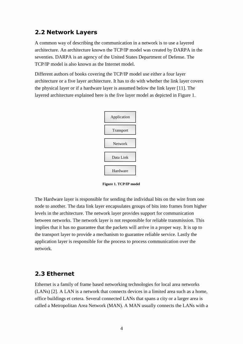
layered architecture explained here is the five layer model as depicted in Figure 1.
The Hardware layer is responsible for sending the individual bits on the wire from one
node to another. The data link layer encapsulates groups of bits into frames from higher
levels in the architecture. The network layer provides support for communication
between networks. The network layer is not responsible for reliable transmission. This
implies that it has no guarantee that the packets will arrive in a proper way. It is up to
the transport layer to provide a mechanism to guarantee reliable service. Lastly the
application layer is responsible for the process to process communication over the
network.
2.3 Ethernet
Ethernet is a family of frame based networking technologies for local area networks
(LANs) [2]. A LAN is a network that connects devices in a limited area such as a home,
office buildings et cetera. Several connected LANs that spans a city or a larger area is
called a Metropolitan Area Network (MAN). A MAN usually connects the LANs with a
Application
Data Link
Network
Transport
Hardware
Figure 1. TCP/IP model
5
high capacity backbone using fiber optical links. Described and of interest in this report
are LANs.
A LAN can be used in a wide variety of topologies such as bus, line or star. It can work
both in half-duplex and full-duplex mode. There are a number of different transmission
mediums that can be used such as coaxial, copper and fiber optic cable. The LAN
technology was developed at Xerox PARC in the seventies. The first IEEE 802.3
standard was published in 1983 and called 10Base5. 10Base5 has a bandwidth of 10
Mbit/s over thick coax cable. The standard is continuously evolving and today there are
Ethernet controllers and switches available with a capacity from 10 Mbit/s [2] to 40
Gbit/s [3].
2.3.1 Topology
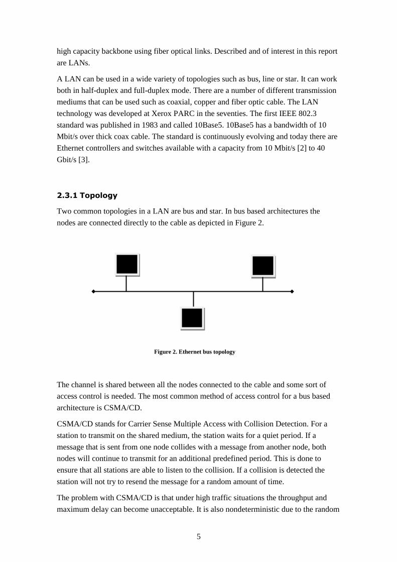
Two common topologies in a LAN are bus and star. In bus based architectures the
nodes are connected directly to the cable as depicted in Figure 2.
The channel is shared between all the nodes connected to the cable and some sort of
access control is needed. The most common method of access control for a bus based
architecture is CSMA/CD.
CSMA/CD stands for Carrier Sense Multiple Access with Collision Detection. For a
station to transmit on the shared medium, the station waits for a quiet period. If a
message that is sent from one node collides with a message from another node, both
nodes will continue to transmit for an additional predefined period. This is done to
ensure that all stations are able to listen to the collision. If a collision is detected the
station will not try to resend the message for a random amount of time.
The problem with CSMA/CD is that under high traffic situations the throughput and
maximum delay can become unacceptable. It is also nondeterministic due to the random
Figure 2. Ethernet bus topology
6
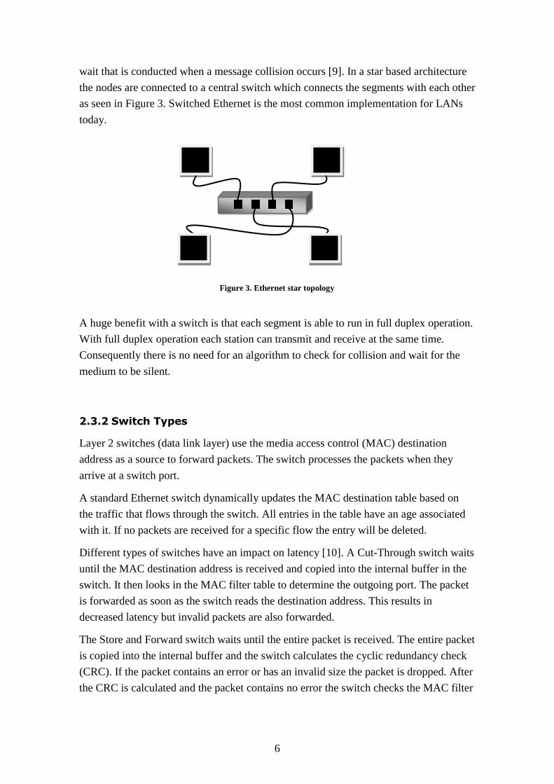
wait that is conducted when a message collision occurs [9]. In a star based architecture
the nodes are connected to a central switch which connects the segments with each other
as seen in Figure 3. Switched Ethernet is the most common implementation for LANs
today.
A huge benefit with a switch is that each segment is able to run in full duplex operation.
With full duplex operation each station can transmit and receive at the same time.
Consequently there is no need for an algorithm to check for collision and wait for the
medium to be silent.
2.3.2 Switch Types
Layer 2 switches (data link layer) use the media access control (MAC) destination
address as a source to forward packets. The switch processes the packets when they
arrive at a switch port.
A standard Ethernet switch dynamically updates the MAC destination table based on
the traffic that flows through the switch. All entries in the table have an age associated
with it. If no packets are received for a specific flow the entry will be deleted.
Different types of switches have an impact on latency [10]. A Cut-Through switch waits
until the MAC destination address is received and copied into the internal buffer in the
switch. It then looks in the MAC filter table to determine the outgoing port. The packet
is forwarded as soon as the switch reads the destination address. This results in
decreased latency but invalid packets are also forwarded.
The Store and Forward switch waits until the entire packet is received. The entire packet
is copied into the internal buffer and the switch calculates the cyclic redundancy check
(CRC). If the packet contains an error or has an invalid size the packet is dropped. After
the CRC is calculated and the packet contains no error the switch checks the MAC filter
Figure 3. Ethernet star topology
7
table for the destination address to determine the outgoing interface. Modern switches
are of Store and Forward type.
2.3.3 Protocol Layout
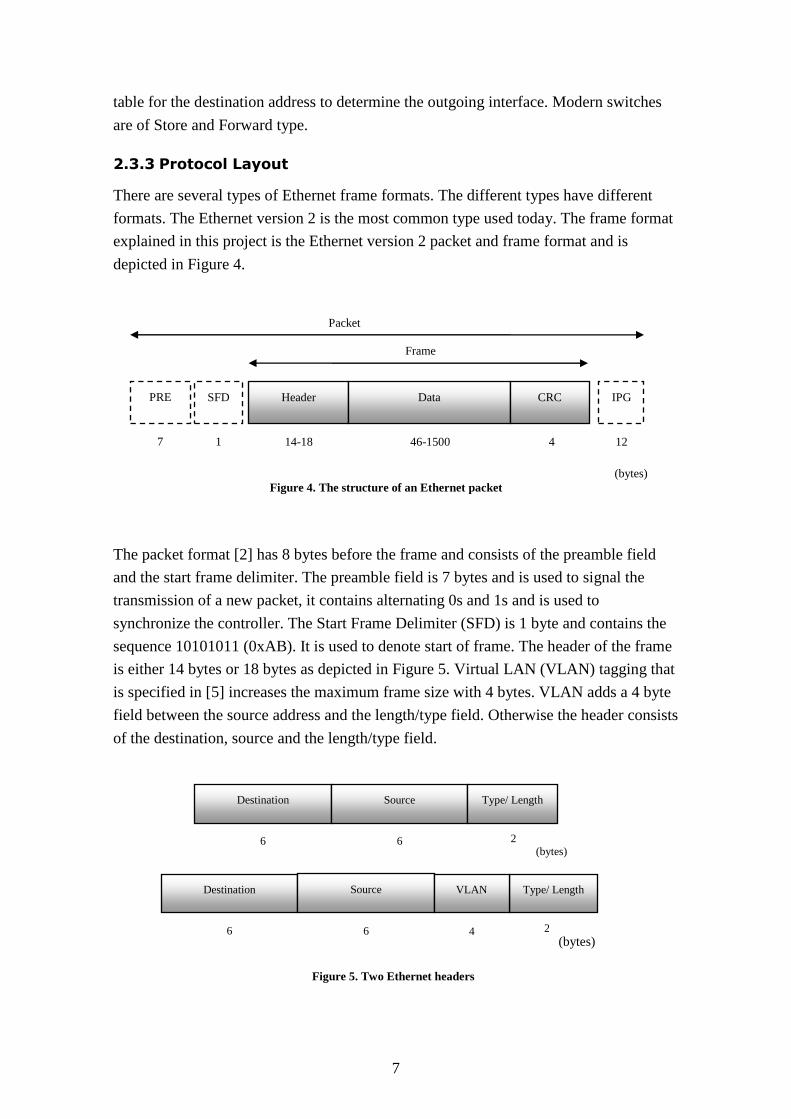
There are several types of Ethernet frame formats. The different types have different
formats. The Ethernet version 2 is the most common type used today. The frame format
explained in this project is the Ethernet version 2 packet and frame format and is
depicted in Figure 4.
The packet format [2] has 8 bytes before the frame and consists of the preamble field
and the start frame delimiter. The preamble field is 7 bytes and is used to signal the
transmission of a new packet, it contains alternating 0s and 1s and is used to
synchronize the controller. The Start Frame Delimiter (SFD) is 1 byte and contains the
sequence 10101011 (0xAB). It is used to denote start of frame. The header of the frame
is either 14 bytes or 18 bytes as depicted in Figure 5. Virtual LAN (VLAN) tagging that
is specified in [5] increases the maximum frame size with 4 bytes. VLAN adds a 4 byte
field between the source address and the length/type field. Otherwise the header consists
of the destination, source and the length/type field.
Frame
Packet
PRE
SFD Header Data CRC IPG
7 1 14-18 46-1500 4
(bytes)
12
2
2
Destination Source Type/ Length
Destination Source Type/ Length VLAN
6 6 4
(bytes) 6 6
(bytes)
Figure 4. The structure of an Ethernet packet
Figure 5. Two Ethernet headers

8
The MAC-address fields are 6 bytes each. One for the destination address and one for
the source address.
The least significant bit in the most significant octet in a MAC-address field is used as
an address type designation bit. If the bit is 0 it indicates that the field contains an
individual address. If bit is 1 it indicates that the field contains a group address that
indentifies none, one or more or all of the stations (multicast). The source field least
significant bit is reserved and set to 0. The second bit in a MAC-address field is used to
distinguish between locally or globally administered addresses. For a globally
administered address the bit is set to 0 otherwise 1. For broadcast bit is set to 1.
So to recap there are basically two type of MAC addresses individual or group/multi-
destination. Individual addresses are associated with a particular station on the network.
Group/multi destination addresses are two kinds. Either they are multicast-group
address or broadcast. The broadcast address is predefined to all ones and defines all
stations on the LAN.
If VLAN tagging is used 2 bytes of the VLAN field are used as the Tag Protocol
Identifier (TPI). A special value is used to identify it as an 802.1Q frame (0x8100). The
other 2 bytes are used as a 3-bit priority field, a 1 bit field that is always set to 0 for
Ethernet switches and a 12 bit VLAN identifier field that is used to identify which
VLAN the frame belongs to.
The length/type field is 2 bytes. If the value is less than or equal to 1500 the field
indicates the number of data bytes in the following data field. If the value is greater than
or equal to 1536, the field indicates the type of client protocol that is carried in the data
field.
Originally the data field supported payloads between 46-1500 bytes. Today there are
extensions called jumbo frames and super jumbo frames. A jumbo frame can carry up to
9000 bytes of payload and a super jumbo frame up to 64 000 bytes. If the length is less
than the minimum, a pad field is added after the data field. The minimum data field size
of 46 bytes is required for correct CSMA/CD protocol operation. If the payload is less
than 46 bytes the pad field is used up to a minimum of 46 bytes for the data + pad field.
The CRC is computed as a function of the frame contents except the preamble and SFD.
Inter Packet Gap (IPG) according to [2] is used to allow a minimum idle period between
transmission of frames. It is used so the devices can prepare for reception of the next
frame. The minimum IPG is specified as 96 bit-times which is equivalent to the time it
takes to transfer a 96 / 8 = 12 byte field. A more detailed description can be found in
[2].

9
2.4 Controller Area Network
Controller Area Network (CAN) was originally designed for automotive applications. It
was introduced in 1986 by Robert Bosh GmbH at the Society of Automotive Engineers
(SAE) congress. Prior to CAN automotive manufacturers connected devices with point-
to-point links as seen in Figure 6. The added weight and the significant amount of
wiring resulted in expensive routing. To reduce cost and wiring a better vehicle network
was needed.
The standard [5] for CAN was published in 1993(CAN 2.0 A) and specified a maximum
transfer rate of 1 Mbit/s. In 1995 an extension was made that increased the CAN
identifier field from 11 to 29 bits (CAN 2.0 B). The standardized application layer
J1939 uses the extended CAN format and it is also the format that is described in this
report.
It is not only in the automotive industry that CAN is used. It is popular in the textile
industry and is also found in ships, trains and aircrafts to name a few.
2.4.1 Communication
The CAN bus is used for communication between ECU’s (electronic control units). In a
truck there are different control units for different parts. For example engine control,
transmission and antilock braking. The ECU’s might need sensor data from sensors
located in the vehicle and the CAN standard was developed to fill this need.
The CAN network is a serial bus network (line topology) as depicted in Figure 7. The
messages are generally not addressed to a specific node but broadcasted. It is up to the
individual node if it is interested in the message or not.
Figure 6. Point to point network
Figure 7. CAN serial bus
10
If a node wants to transmit on the bus it waits until the bus is free. All messages have an
identifier that also works as the priority of the message. The maximum payload for a
CAN message is only 8 bytes. It was designed to be used to send signals to trigger
events or to send sensor data.
The CAN network uses wired-AND logic and the binary model of dominant and
recessive bits. A dominant bit is a logical 0 and recessive is a logical 1. If at the same
time a node transmits a dominant bit (0) and another node transmits a recessive bit (1) a
dominant (0) is seen on the bus, the result is the logical AND between the two.
2.4.2 Protocol Layout
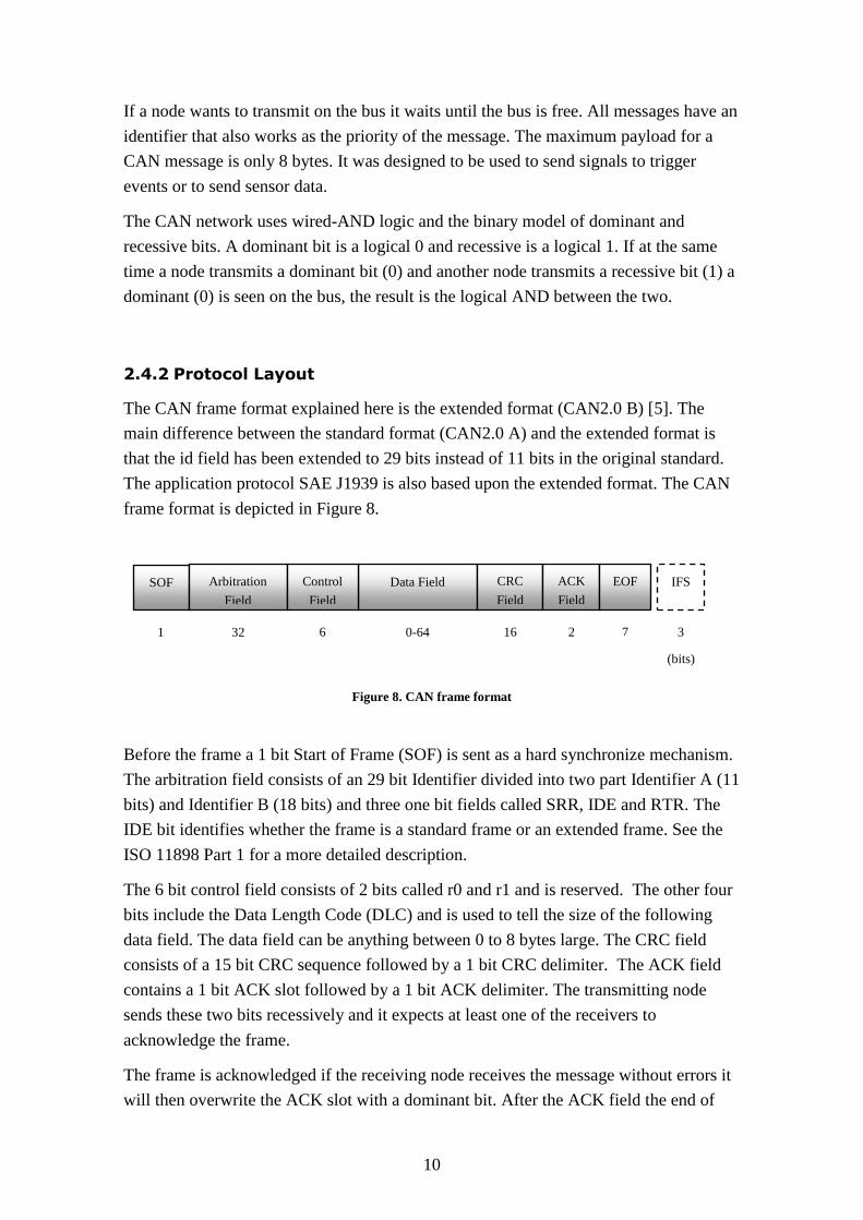
The CAN frame format explained here is the extended format (CAN2.0 B) [5]. The
main difference between the standard format (CAN2.0 A) and the extended format is
that the id field has been extended to 29 bits instead of 11 bits in the original standard.
The application protocol SAE J1939 is also based upon the extended format. The CAN
frame format is depicted in Figure 8.
Before the frame a 1 bit Start of Frame (SOF) is sent as a hard synchronize mechanism.
The arbitration field consists of an 29 bit Identifier divided into two part Identifier A (11
bits) and Identifier B (18 bits) and three one bit fields called SRR, IDE and RTR. The
IDE bit identifies whether the frame is a standard frame or an extended frame. See the
ISO 11898 Part 1 for a more detailed description.
The 6 bit control field consists of 2 bits called r0 and r1 and is reserved. The other four
bits include the Data Length Code (DLC) and is used to tell the size of the following
data field. The data field can be anything between 0 to 8 bytes large. The CRC field
consists of a 15 bit CRC sequence followed by a 1 bit CRC delimiter. The ACK field
contains a 1 bit ACK slot followed by a 1 bit ACK delimiter. The transmitting node
sends these two bits recessively and it expects at least one of the receivers to
acknowledge the frame.
The frame is acknowledged if the receiving node receives the message without errors it
will then overwrite the ACK slot with a dominant bit. After the ACK field the end of
SOF Arbitration
Field
Data Field Control
Field
CRC
Field
ACK
Field
EOF IFS
1 32 6 16 2 7 3 0-64
(bits)
Figure 8. CAN frame format
11
frame field (EOF) that denotes the end of the CAN frame. The Inter Frame Space (IFS)
separates messages from each other. It is the minimum amount of space between
adjacent frames.
2.4.3 Arbitration
When arbitrating all the transmitters compare the level of the bit transmitted with the
level that is monitored on the bus. If the bits are equal the node continues. If they are
not equal the node stops transmitting. As a result the CAN message with the highest
priority will succeed and the node that is trying to transmit the lower priority message
will sense this and stop. All messages that are sent are available to all nodes on the
network and it is up the each node if it is interested in the message.
2.4.4 Bit-Stuffing
The bit encoding in CAN is non-return to zero (NRZ). With NRZ the signal will remain
at 0 for multiple bits of 0 and the other way around. To prevent transceivers and
receivers to lose synchronization a stuff bit is used. The bit stuffing causes a variable
packet size that depends on the bit representation of the packet.
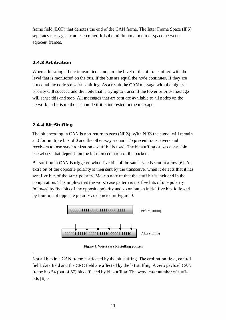
Bit stuffing in CAN is triggered when five bits of the same type is sent in a row [6]. An
extra bit of the opposite polarity is then sent by the transceiver when it detects that it has
sent five bits of the same polarity. Make a note of that the stuff bit is included in the
computation. This implies that the worst case pattern is not five bits of one polarity
followed by five bits of the opposite polarity and so on but an initial five bits followed
by four bits of opposite polarity as depicted in Figure 9.
Not all bits in a CAN frame is affected by the bit stuffing. The arbitration field, control
field, data field and the CRC field are affected by the bit stuffing. A zero payload CAN
frame has 54 (out of 67) bits affected by bit stuffing. The worst case number of stuff-
bits [6] is
00000 1111 0000 1111 0000 1111
000001 11110 00001 11110 00001 11110 After stuffing
Figure 9. Worst case bit stuffing pattern
Before stuffing
12
where d is equal to the data payload in bytes. As a result the minimum CAN frame can
be anywhere from 67 bits to 80 bits depending on the bit sequence.
2.5 J1939
J1939 is the application protocol standard Scania uses when sending messages on the
CAN bus. J1939 defines message identifiers and the message content. Its focus was
primarily to standardize the messages for the engine, transmission and brake
applications but has later been extended to various functions and applications. It was
created in the beginning of the nineties by a committee called Society of Automotive
Engineers (SAE).
2.5.1 Protocol Layout
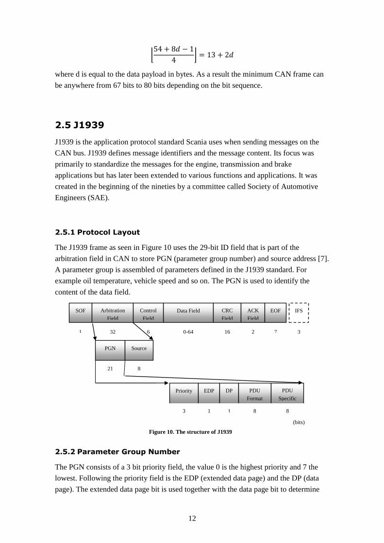
The J1939 frame as seen in Figure 10 uses the 29-bit ID field that is part of the
arbitration field in CAN to store PGN (parameter group number) and source address [7].
A parameter group is assembled of parameters defined in the J1939 standard. For
example oil temperature, vehicle speed and so on. The PGN is used to identify the
content of the data field.
2.5.2 Parameter Group Number
The PGN consists of a 3 bit priority field, the value 0 is the highest priority and 7 the
lowest. Following the priority field is the EDP (extended data page) and the DP (data
page). The extended data page bit is used together with the data page bit to determine
8
SOF Arbitration
Field
Data Field Control
Field
CRC
Field
ACK
Field
EOF IFS
1 32 6 16 2 7 3 0-64
PGN Source
Priority EDP DP PDU
Format
PDU
Specific
21
3 1 1 8 8
(bits)
Figure 10. The structure of J1939
13
the structure of the CAN identifier of the can data frame. The definitions for all the
combinations can be seen in [7]. The PDU format is an 8 bit field and is one of the
fields used to identify the parameter group number. Parameter group number is used to
identify or label commands, data, requests and acknowledgments. A parameter is data
such as engine rpm. It is common to group parameters together to utilize all the 8 bytes
payload in a single CAN frame.
PDU specific field is 8 bits and can be a destination address, group extension. It
depends on PDU format, if the value of the PDU format is below 240 (0xF0) the PDU
specific field is a destination address. The destination field contains the specific address
to which the CAN message is sent. The value 255 is a global destination address and
requires that all the nodes listen and respond. If it is between 240-255 (0xF0-0xFF) then
the field contains a group extension. The group extension extends the number of
parameter group numbers. Without the group extension you have 240 possible
parameter group numbers per data page. There are two possible data pages (DP field
can be 0 or 1) so that gives a total of
With the group extension the PDU specific field together with the four least significant
bits in the PDU format field provides
The total parameter group numbers are
When more than 8 bytes is needed for a Parameter group the data is split into multiple
CAN data frames. Examples of Parameter groups can be found in [8].
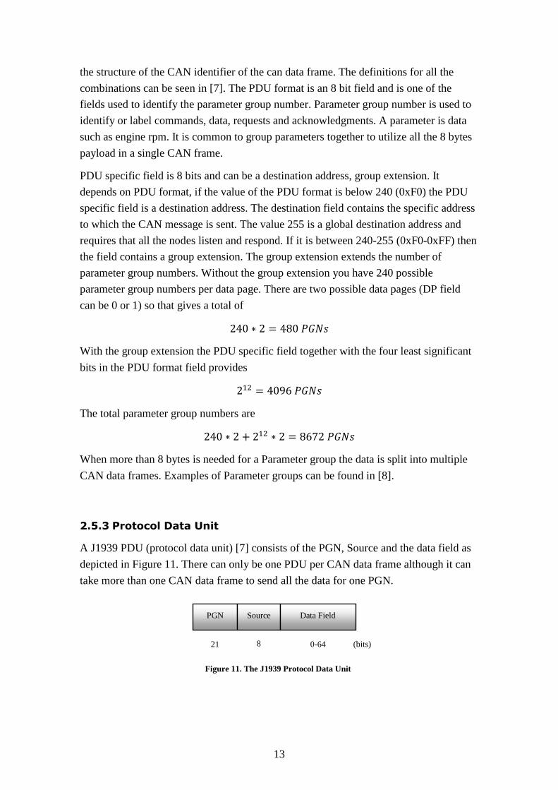
2.5.3 Protocol Data Unit
A J1939 PDU (protocol data unit) [7] consists of the PGN, Source and the data field as
depicted in Figure 11. There can only be one PDU per CAN data frame although it can
take more than one CAN data frame to send all the data for one PGN.
PGN Source
21 8 0-64 (bits)
Data Field
Figure 11. The J1939 Protocol Data Unit
14
2.6 FlexRay
FlexRay is an automotive communication protocol. It was designed as an improvement
over CAN and supports high data rates up to 20 Mbit/s. The protocol supports both time
triggered and event triggered communication. It uses a bus in a comparable way to
CAN. It supports dual redundancy and combined with the time triggered
communication it meets the reliability requirements for future applications such as
brake-by-wire. It is currently in use today by Audi, BMW to name a few [43].
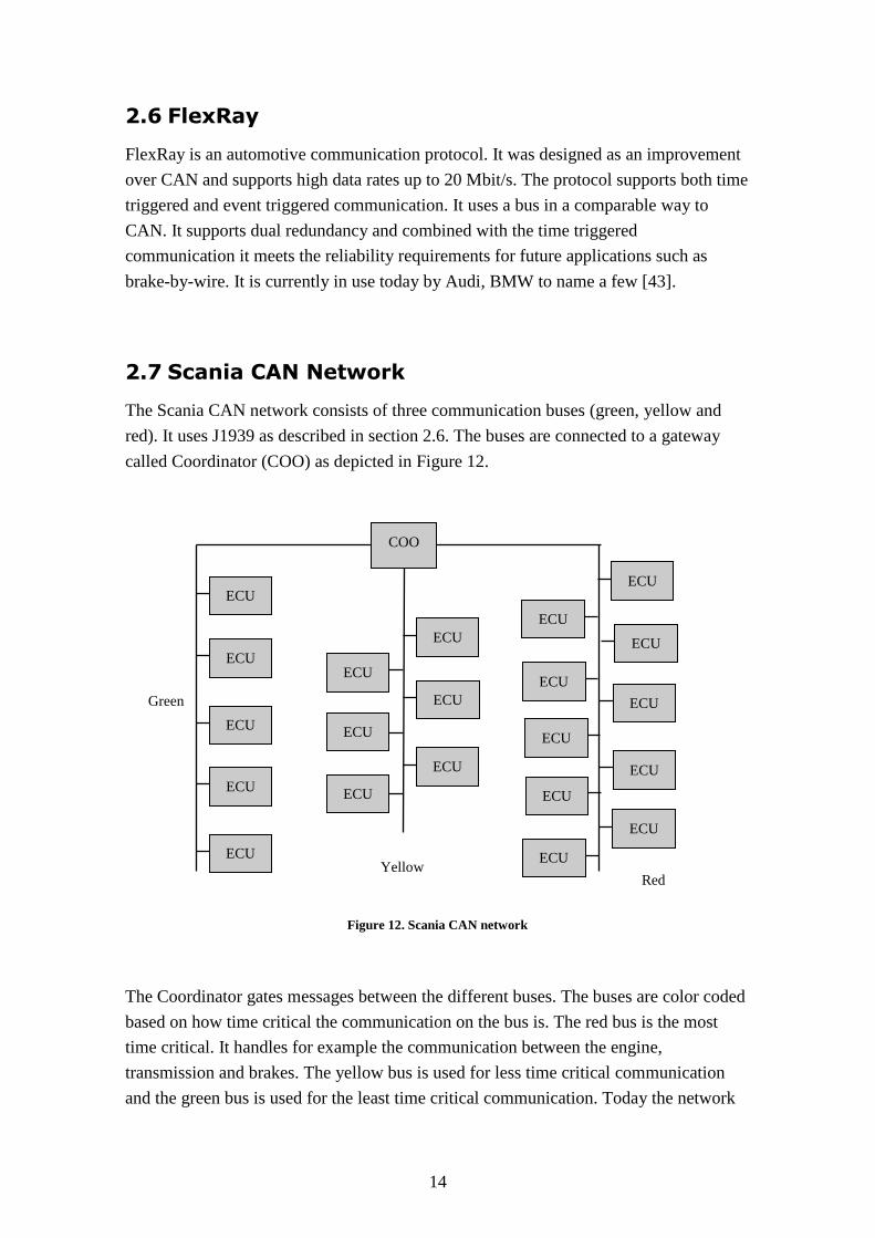
2.7 Scania CAN Network
The Scania CAN network consists of three communication buses (green, yellow and
red). It uses J1939 as described in section 2.6. The buses are connected to a gateway
called Coordinator (COO) as depicted in Figure 12.
The Coordinator gates messages between the different buses. The buses are color coded
based on how time critical the communication on the bus is. The red bus is the most
time critical. It handles for example the communication between the engine,
transmission and brakes. The yellow bus is used for less time critical communication
and the green bus is used for the least time critical communication. Today the network
ECU
ECU
ECU
ECU
ECU
ECU
ECU
ECU
ECU
ECU
ECU
COO
ECU
ECU
ECU
ECU
ECU
Yellow Red
Green
ECU
ECU
ECU
ECU
ECU
Figure 12. Scania CAN network
15
load on the buses is reaching the limit of what is possible using the current CAN bus.
My suggestion is to create a converged Ethernet backbone with nodes capable of high
bandwidth transmissions.
High bandwidth applications such as infotainment and driver assist system (camera
system et cetera) require an updated architecture. To converge the communication more
buses should be connected through the use of gateways. If Ethernet is adopted it could
be used for the diagnostic interface instead of the current interface over CAN.
Diagnostics could then be performed using a notebook with a standard TCP/IP stack.
There is currently a standard in development for diagnostic over IP called DoIP [42].
Flashing of ECU’s is also a bottleneck on the current CAN bus that could be improved
using Ethernet.
The architecture requires a suitable Ethernet protocol for communication over the
Ethernet backbone. In the following chapter different Ethernet solutions are described
and explained. The goal is to find a suitable protocol for real-time communication.

16
3 Available Technology
This chapter explains the three different Ethernet technologies studied in this project. A
summary of the difference of the protocol is described in chapter 3.4
When selecting the Ethernet protocols it is important that they have real-time
characteristics, solutions for the unrestrained buffer contention in the switch and how to
give guarantees of an upper bound on the latency. The three selected protocols are
AFDX, TTEthernet and Ethernet AVB. AFDX is selected because it is an established
standard currently in use in the airline industry. TTEthernet is an interesting technology
that supports time triggered communication and can be an alternative to the time
triggered protocol FlexRay that is proposed as the successor to the CAN bus. Last but
not least Ethernet AVB, a standard from IEEE and aimed at the consumer/professional
audio video market that has the capability to hit a large market and as a consequence
create lower cost Ethernet hardware with real-time support.
3.1 AFDX
Avionics Full Duplex Switched Ethernet (AFDX) is specified in ARINC 664 Part 7. It
is a standard for a deterministic data network based on 10 or 100 Mbit/s switched
Ethernet. It was initiated by Airbus in the design and creation of the A380 aircraft. The
predecessor to AFDX, ARINC 429 is a point to multipoint bus system that supports
one-to-one or one-to-many connections. AFDX is an improvement compared to ARINC
429 due to the higher data transfer rate (approximately one thousand times faster) and
less wiring is needed which reduces wiring runs and the weight [12].
The most important elements of an AFDX network are
AFDX End System: The end system is the interface between the subsystems (for
example flight control computer) and the network.
AFDX Switch: A full-duplex switch. The switch forwards Ethernet frames to the
correct destination.
AFDX Virtual Links: A virtual link is a unidirectional virtual connection from
one-to-one or one-to-many End Systems.
17
3.1.1 Supported Traffic
AFDX supports rate constrained traffic. The AFDX network provides an upper bound
on latency and determinism [18] through modifications and restrictions to the Ethernet
protocol in the following way
Bandwidth partition: Maximum data packet size and scheduling of packets to
allow guaranteed bandwidth
Defined packet order: Packets are received in the same order they are sent
Dual Redundancy: An end station transmit the same packet out of two ports
The communication protocol is derived from IEEE 802.3 MAC addressing, User
Datagram (UDP) and Internet Protocol (IP).
3.1.2 Virtual Links
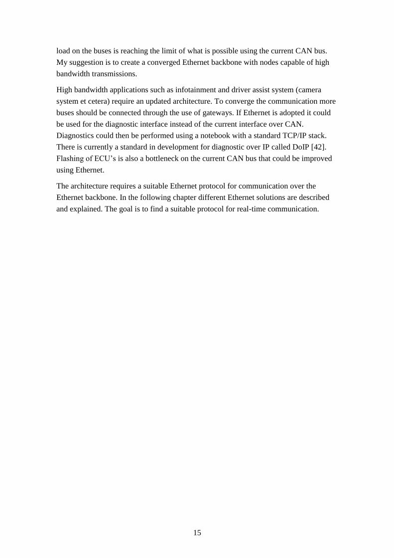
Virtual links partition the switched network into communication channels with a
predefined link bandwidth and scheduling time. The virtual link is unidirectional and
uses a 16-bit identifier that is part of the MAC destination address as seen in Figure 13.
The switches are configured to route packets based on the virtual link ID. One Virtual
link will have one or more predefined end systems that the switch sends packets to. A
virtual link can only have one sending end system but multiple receiving end systems
[13]. A notice can be made that all MAC addresses are locally administered and of
multicast type according to the IEEE 802.3 standard (the second and the least
significant bit of the most significant address octet is set to 1) .
The virtual link has two parameters
Bandwidth Allocation Gap (BAG) , the BAG value restrict how often the virtual
link is scheduled (how often it is possible to send a message on the virtual link).
In the AFDX standard the valid range for the BAG value is in powers of 2 from
1 to 128 ms.
Lmax is the largest Ethernet frame size the virtual link can transmit (IP layer
takes care of segmentation and reassembly).
32 bit constant field
0000 0011 0000 0000 0000 0000 0000 0000
Virtual link ID
16 bit unsigned int
Figure 13. AFDX MAC destination address
18
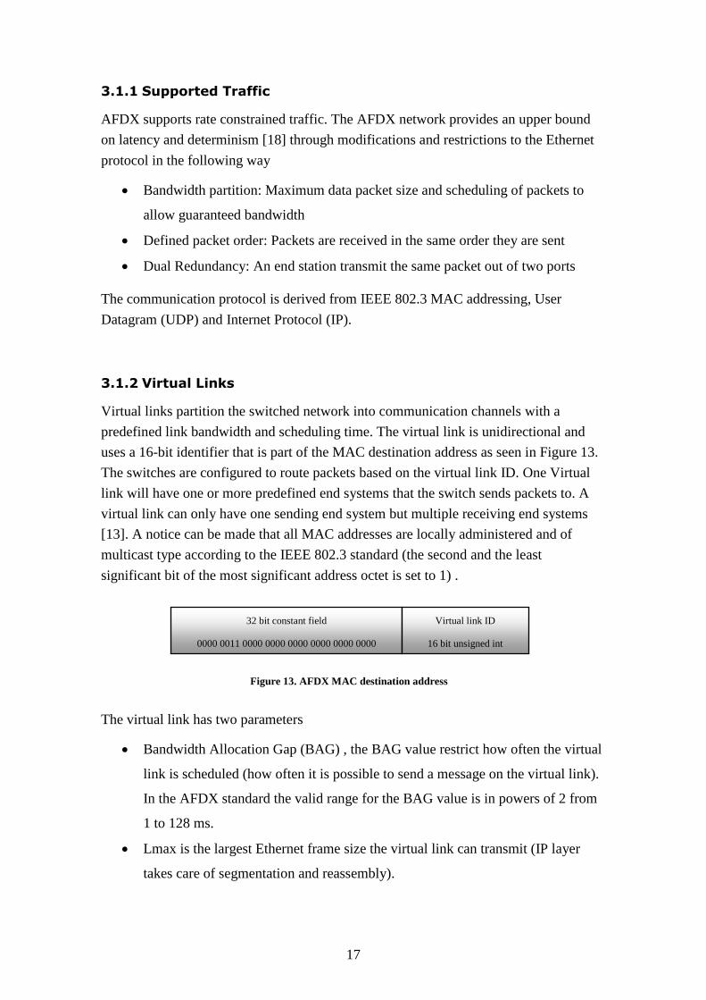
Figure 14 below exemplifies two virtual links in an AFDX network.
As an example a virtual link with a BAG of 8 ms and an Lmax of 200 bytes. The
maximum bandwidth in kbit/s on the virtual link is
/s
Choosing an appropriate BAG for multiple messages transmitted through the same
virtual link can be done in the following way. If you have three messages m1, m2 and
m3, with a frequency of 15, 30 and 40 Hz, you add their frequencies together
The period for a frequency of 85 Hz is 11.8 ms. The closest BAG that is less than 11.8
ms is 8 ms. A period of 8 ms corresponds to a frequency of 125 Hz.
If m3is the message with the highest frequency of 40 Hz and its deadline is equal to its
period (25 ms). The worst case scenario happens if all the messages arrives within a
single scheduling period. Message m3 is still scheduled and transmitted before its
deadline because the virtual link scheduling frequency (125 Hz) is larger than the
combined frequency (85 Hz) of the three messages as seen in Figure 15 below.
VL1
VL2
Schedule/Transmit
time
Incoming
messages
0 8 16 24 ms
m2
m1
m3
Figure 15. AFDX scheduling three messages
Figure 14. AFDX virtual link routing

19
Assured service is an important concept for the AFDX network. The bandwidth and the
end-to-end latency for each virtual link are guaranteed. The specification does not cover
guarantee of packet delivery. It is up to the individual application to handle transmission
acknowledgement and retransmission requests [15].
3.1.3 Virtual Link Scheduling
The virtual link scheduler in each end system is responsible for the transmit schedule.
Applications send messages to the communication ports. The messages are encapsulated
within the UDP, IP and Ethernet frames. It makes sure that the bandwidth limit based on
the virtual link BAG and Lmax parameters are under control and it multiplexes all the
virtual links as depicted in Figure 16. The multiplexing of virtual links can introduce
jitter if they are scheduled in the same time slot [12].
3.1.4 End System and subsystems
The end system in an AFDX network is the interface between the subsystems and the
AFDX switch. One computer system encapsulates multiple subsystems and an end
system as seen in Figure 17. The subsystems are partitioned and isolated from each
other. It is implemented by restricting the address space and limiting the amount of
processor time each subsystem can use. Actuators and sensors are connected to each
subsystem, the applications running in each subsystem reads data from the actuators and
sensors and transmits messages to the end system.
VL3
VL1
VL2 Virtual link
scheduler
End system
Subsystem
Subsystem
Subsystem
Sensors
Actuators
Sensors
Figure 16. AFDX virtual link scheduling
Figure 17. AFDX computer system
20
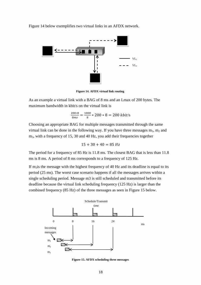
An AFDX network is dual redundant as depicted in Figure 18. The networks are called
the A and B network. When the end system receives a message on either the A or the B
network the message is first controlled by the integrity checker. It detects and eliminates
invalid frames. The redundancy management is responsible for determining whether it
should drop the packet or pass it to the upper layer of the protocol stack. This is based
on if it has already received a packet with the same sequence number and associated
with same virtual link. The applications communicate with each other by sending
messages using communication ports. End systems are identified with two 8-bit IDs: the
Network ID and Equipment ID. The identifiers are used to create the source MAC
address and the unicast IP address [14].
3.1.5 Communication ports
There are three types of ports described in the AFDX standard. They are queuing,
sampling and service access ports (SAP) [12].
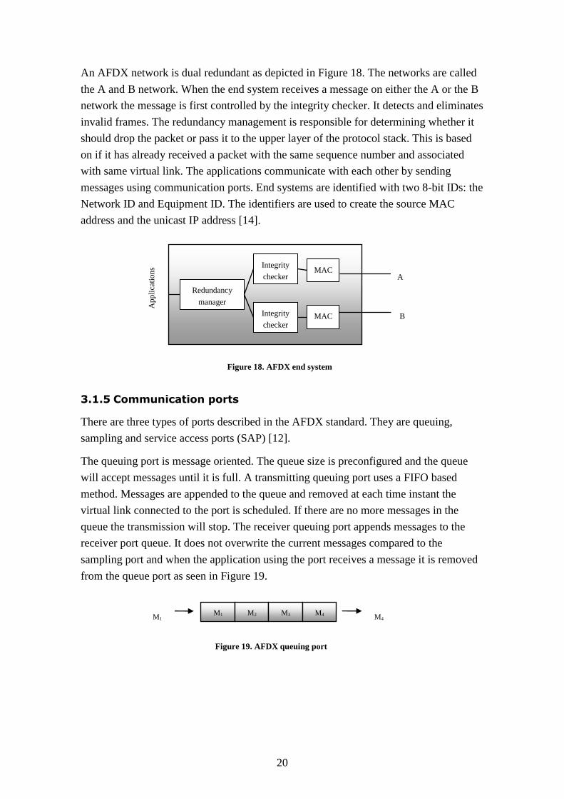
The queuing port is message oriented. The queue size is preconfigured and the queue
will accept messages until it is full. A transmitting queuing port uses a FIFO based
method. Messages are appended to the queue and removed at each time instant the
virtual link connected to the port is scheduled. If there are no more messages in the
queue the transmission will stop. The receiver queuing port appends messages to the
receiver port queue. It does not overwrite the current messages compared to the
sampling port and when the application using the port receives a message it is removed
from the queue port as seen in Figure 19.
Ap
pli
cati
on
s MAC
MAC
A
B
Redundancy
manager
Integrity
checker
Integrity
checker
M1 M2 M3 M4 M1 M4
Figure 18. AFDX end system
Figure 19. AFDX queuing port
21
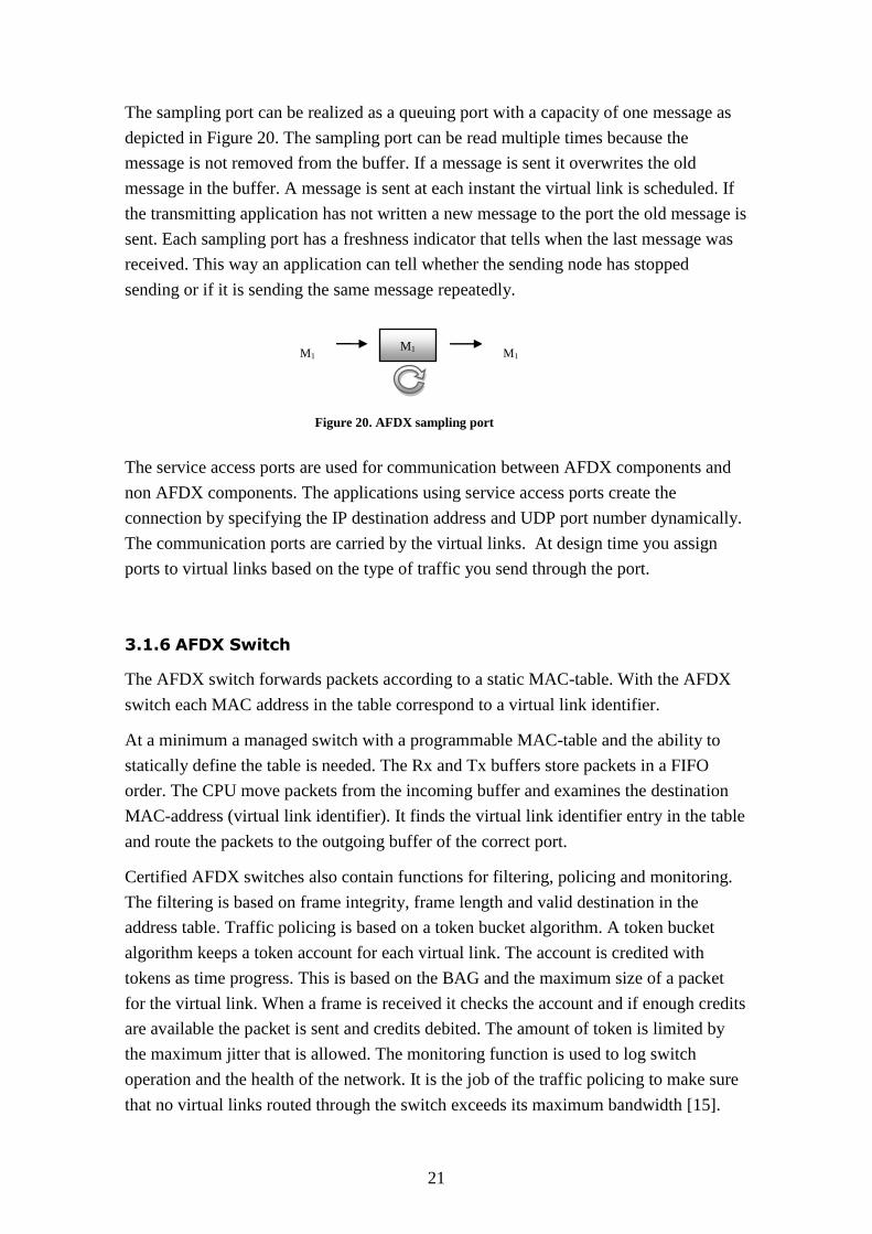
The sampling port can be realized as a queuing port with a capacity of one message as
depicted in Figure 20. The sampling port can be read multiple times because the
message is not removed from the buffer. If a message is sent it overwrites the old
message in the buffer. A message is sent at each instant the virtual link is scheduled. If
the transmitting application has not written a new message to the port the old message is
sent. Each sampling port has a freshness indicator that tells when the last message was
received. This way an application can tell whether the sending node has stopped
sending or if it is sending the same message repeatedly.
The service access ports are used for communication between AFDX components and
non AFDX components. The applications using service access ports create the
connection by specifying the IP destination address and UDP port number dynamically.
The communication ports are carried by the virtual links. At design time you assign
ports to virtual links based on the type of traffic you send through the port.
3.1.6 AFDX Switch
The AFDX switch forwards packets according to a static MAC-table. With the AFDX
switch each MAC address in the table correspond to a virtual link identifier.
At a minimum a managed switch with a programmable MAC-table and the ability to
statically define the table is needed. The Rx and Tx buffers store packets in a FIFO
order. The CPU move packets from the incoming buffer and examines the destination
MAC-address (virtual link identifier). It finds the virtual link identifier entry in the table
and route the packets to the outgoing buffer of the correct port.
Certified AFDX switches also contain functions for filtering, policing and monitoring.
The filtering is based on frame integrity, frame length and valid destination in the
address table. Traffic policing is based on a token bucket algorithm. A token bucket
algorithm keeps a token account for each virtual link. The account is credited with
tokens as time progress. This is based on the BAG and the maximum size of a packet
for the virtual link. When a frame is received it checks the account and if enough credits
are available the packet is sent and credits debited. The amount of token is limited by
the maximum jitter that is allowed. The monitoring function is used to log switch
operation and the health of the network. It is the job of the traffic policing to make sure
that no virtual links routed through the switch exceeds its maximum bandwidth [15].
M1 M1 M1
Figure 20. AFDX sampling port
22
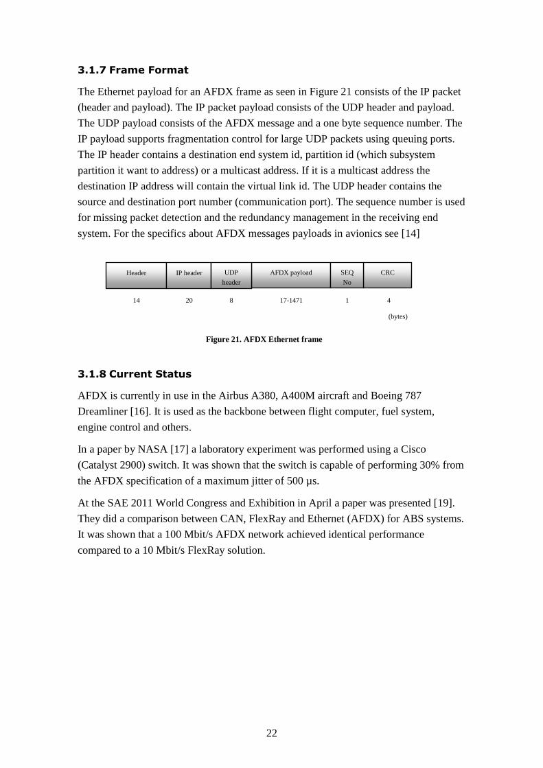
3.1.7 Frame Format
The Ethernet payload for an AFDX frame as seen in Figure 21 consists of the IP packet
(header and payload). The IP packet payload consists of the UDP header and payload.
The UDP payload consists of the AFDX message and a one byte sequence number. The
IP payload supports fragmentation control for large UDP packets using queuing ports.
The IP header contains a destination end system id, partition id (which subsystem
partition it want to address) or a multicast address. If it is a multicast address the
destination IP address will contain the virtual link id. The UDP header contains the
source and destination port number (communication port). The sequence number is used
for missing packet detection and the redundancy management in the receiving end
system. For the specifics about AFDX messages payloads in avionics see [14]
3.1.8 Current Status
AFDX is currently in use in the Airbus A380, A400M aircraft and Boeing 787
Dreamliner [16]. It is used as the backbone between flight computer, fuel system,
engine control and others.
In a paper by NASA [17] a laboratory experiment was performed using a Cisco
(Catalyst 2900) switch. It was shown that the switch is capable of performing 30% from
the AFDX specification of a maximum jitter of 500 µs.
At the SAE 2011 World Congress and Exhibition in April a paper was presented [19].
They did a comparison between CAN, FlexRay and Ethernet (AFDX) for ABS systems.
It was shown that a 100 Mbit/s AFDX network achieved identical performance
compared to a 10 Mbit/s FlexRay solution.
Header AFDX payload CRC IP header UDP
header
SEQ
No
4 1 17-1471 8 20 14
(bytes)
Figure 21. AFDX Ethernet frame
23
3.2 TTEthernet
TT-Ethernet was the name of a research project conducted by the Real-Time System
Group at Vienna University of Technology in 2000. The academic project presented a
time triggered solution over Ethernet hardware. The goal was to produce a solution for
safety-critical real-time systems in automotive, avionics and railway domains. [25]
TTEthernet is a shared development involving TT-Tech and Honeywell that continued
and improved the previous academic research project. It introduced scalable fault
tolerance and support for communication with different real-time requirements. As a
result three different traffic classes were introduced (time triggered rate constrained and
best effort traffic). The protocol supports fault tolerant configuration in a similar way to
the AFDX protocol with two ports per node and two independent switches.
3.2.1 Supported traffic
TT-Ethernet supports three types of traffic classes
Time triggered traffic (TT)
Rate constrained traffic (RC)
Best effort traffic (BE)
Time triggered communication sends traffic based on global synchronized time. The
time triggered packets are sent at predefined times and take priority over all other traffic
types in the network. Messages from higher layer protocol like IP or UDP can be made
time-triggered without modification to the messages themselves. The actual overhead
from the protocol that enables time triggered traffic is sent in special messages.
TTEthernet protocol with time triggered communication is as a result only concerned
about when a message is sent not what specific content the message has. Time triggered
traffic is used for applications that require low latency, little jitter and high deterministic
behavior [20].
Rate constrained messages are used for applications with less stringent requirements
than time triggered communication. The rate constrained traffic supported in
TTEthernet is identical to the previous described technology AFDX. The AFDX
standard segments the network into virtual links with predefined bandwidth limits, the
traffic is shaped with a periodic leaky bucket in each end station. This creates a low
upper limit on the buffers in each switch and a bounded latency on each virtual link.
The rate constrained traffic is not sent based on a global synchronized time. A rate
constrained message can suffer some delay if a time triggered message is transmitted
via the same outgoing port at the same time [20].
24
Best effort traffic has the lowest priority. Both rate constrained and time triggered traffic
has priority over best effort traffic that can be delayed or discarded. No guarantees are
given and switches can drop messages if the buffers overflow. Best effort traffic should
use some sort of acknowledgement such as TCP/IP otherwise it is possible to lose
messages [20].
3.2.2 Time Triggered Synchronization
The time synchronization is a significant part to support time triggered traffic. The
global time synchronization in TT-Ethernet uses frames called protocol control frames
(PCF) to synchronize the nodes with each other. The synchronization domain is
periodically resynchronized in intervals called integration cycles. Such a cycle could be
one millisecond but depends on the amount of the acceptable clock drift [20]. A
synchronization domain in TT-Ethernet contains three types of devices
Synchronization Master
Synchronization Client
Compression Master
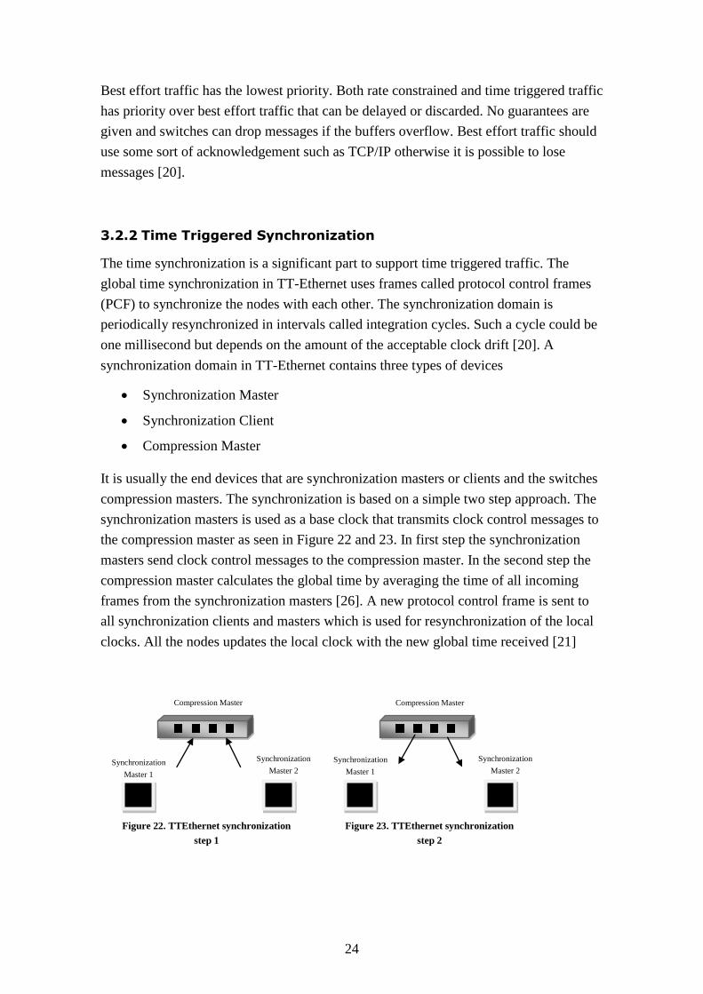
It is usually the end devices that are synchronization masters or clients and the switches
compression masters. The synchronization is based on a simple two step approach. The
synchronization masters is used as a base clock that transmits clock control messages to
the compression master as seen in Figure 22 and 23. In first step the synchronization
masters send clock control messages to the compression master. In the second step the
compression master calculates the global time by averaging the time of all incoming
frames from the synchronization masters [26]. A new protocol control frame is sent to
all synchronization clients and masters which is used for resynchronization of the local
clocks. All the nodes updates the local clock with the new global time received [21]
Compression Master
Synchronization
Master 2
Synchronization
Master 1
Compression Master
Synchronization
Master 2 Synchronization
Master 1
Figure 22. TTEthernet synchronization
step 1
Figure 23. TTEthernet synchronization
step 2

25
3.2.3 TTEthernet Switch
The TTEthernet switch can differentiate between time triggered traffic and other types
of traffic by using the content of the Ethernet destination address [22]. When other
traffic types such as rate constrained and best effort traffic is mixed it is important that
lower priority traffic does not interfere with time triggered traffic. There are three
different integration methods that is used when contention occurs on the outgoing ports
Preemption
Timely Block
Shuffling
A Preemptive method preempts low priority traffic if a time triggered message is
scheduled at the same time instant. Such a method provides high real-time quality
because the outgoing ports for a time triggered message is free at the same instant as the
time triggered message arrives. A negative aspect is the generation of false messages
due to truncation.
Timely Block makes sure that the port is free based on the amount of time it takes to
send a low priority message. If it is calculated that the low priority message intrudes on
the global time when a triggered message is scheduled it is blocked. It provides the
same real-time qualities as the preemptive method but may be resource inefficient.
Shuffling delays the high priority message if a low priority message is already
transmitting. Such a method provides resource efficiency but low real-time quality.
In the paper TTEthernet Dataflow Concept [22] it is stated that TTEthernet uses timely
block and shuffling but prototypes of preemptive switches exists.
A traffic schedule for the time triggered communication needs to be uploaded to all the
switches in the network that have connected devices using time triggered traffic. The
switch is reserved for time triggered traffic at the instants defined in the schedule.
26
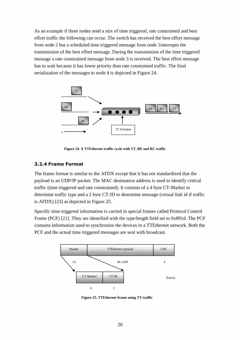
As an example if three nodes send a mix of time triggered, rate constrained and best
effort traffic the following can occur. The switch has received the best effort message
from node 2 but a scheduled time triggered message from node 1interrupts the
transmission of the best effort message. During the transmission of the time triggered
message a rate constrained message from node 3 is received. The best effort message
has to wait because it has lower priority than rate constrained traffic. The final
serialization of the messages to node 4 is depicted in Figure 24.
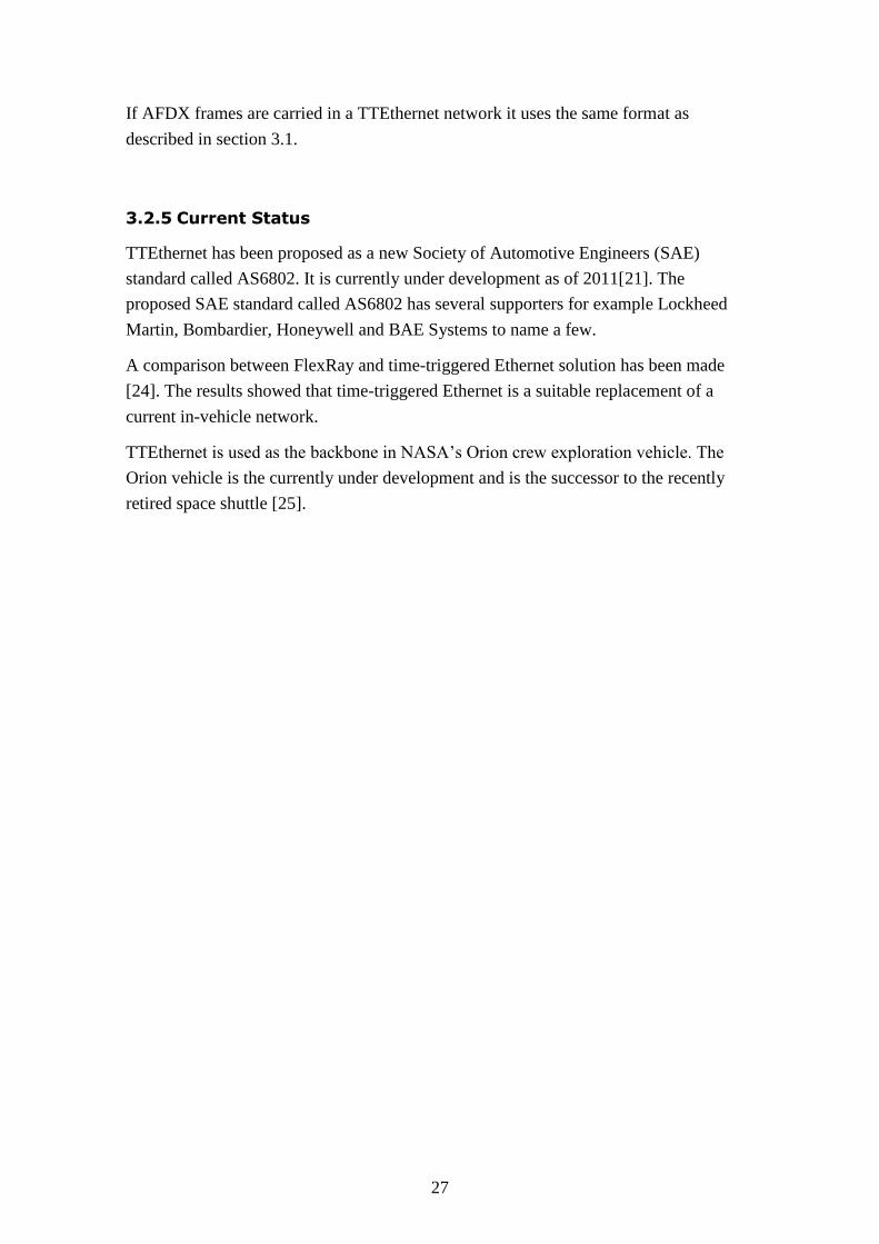
3.2.4 Frame Format
The frame format is similar to the AFDX except that it has not standardized that the
payload is an UDP/IP packet. The MAC destination address is used to identify critical
traffic (time triggered and rate constrained). It consists of a 4 byte CT-Marker to
determine traffic type and a 2 byte CT-ID to determine message (virtual link id if traffic
is AFDX) [23] as depicted in Figure 25.
Specific time triggered information is carried in special frames called Protocol Control
Frame (PCF) [21]. They are identified with the type/length field set to 0x891d. The PCF
contains information used to synchronize the devices in a TTEthernet network. Both the
PCF and the actual time triggered messages are sent with broadcast.
TT
BE
RC
TT Schedule
RC BE
t
TT
Header TTEthernet payload CRC
4 46-1500 14
(bytes) CT-Marker CT-ID
4 2
Figure 24. A TTEthernet traffic cycle with TT, BE and RC traffic
Figure 25. TTEthernet frame using TT-traffic
27
If AFDX frames are carried in a TTEthernet network it uses the same format as
described in section 3.1.
3.2.5 Current Status
TTEthernet has been proposed as a new Society of Automotive Engineers (SAE)
standard called AS6802. It is currently under development as of 2011[21]. The
proposed SAE standard called AS6802 has several supporters for example Lockheed
Martin, Bombardier, Honeywell and BAE Systems to name a few.
A comparison between FlexRay and time-triggered Ethernet solution has been made
[24]. The results showed that time-triggered Ethernet is a suitable replacement of a
current in-vehicle network.
TTEthernet is used as the backbone in NASA’s Orion crew exploration vehicle. The
Orion vehicle is the currently under development and is the successor to the recently
retired space shuttle [25].
28
3.3 Ethernet AVB
Ethernet AVB is the IEEE take on a real-time Ethernet solution. AVB stands for Audio
Video Bridging and the original work was carried out by an 802.3 Ethernet study group
that was investigating next generation digital homes. The work was moved over to an
802.1 AVB task group because most of the work needed to be done on the architectural
and upper protocol layer. The goal of the group was to create a standard that could
guarantee Quality of Service (QOS) for time critical services. The AVB standard has
since then attracted interest not only from the consumer market but also from the
automotive industry [27] [28] [31] [33] [35].
There are three specifications that Ethernet AVB is based on
IEEE 802.1as, provides precise timing and accurate synchronization for streams.
IEEE 802.1Qat, stream reservation protocol that provides support for the
receiving node applications to request a reserved bandwidth path in the network
from sending node to receiving node.
IEEE 802.1Qav, rules that will ensure the network latency for a stream in the
network and guarantees latency for highest traffic class.
There is also a fourth standard IEE 802.1BA that has the purpose of specifying default
configurations and profiles to aid manufacturers creating AVB compatible products.
3.3.1 Supported Traffic
Ethernet AVB supports rate constrained traffic using the IEEE 802.1Qat and IEEE
802.1Qav standards. Real-time traffic is divided into class A and class B. Best effort
traffic is also supported. Ethernet AVB uses the IEEE 802.1Q standard that adds VLAN
tagging support. It includes a 3-bit priority field that indicate frame priority with values
ranging from 0(best effort) to 7(highest).
3.3.2 IEEE 802.1as Time Synchronization
To synchronize an AVB stream in the network the devices will from time to time
exchange timing information. The information allows the devices to synchronize their
time base reference clocks with each other. It is derived from the IEEE 1588 standard
and uses UDP over IP and the time base reference is derived from a high frequency 8
kHz clock source [27].
Devices in the network that supports AVB create a timing domain and within the
domain a single device is selected Grand Master Clock. The master timing signal is sent
29
to all slaves in the domain so all the slaves are synchronized with the master clock. The
Grand Master Clock can automatically be selected or manually configured. When AVB
capable devices are physically connected to the switch they will start to send capability
messages to each other. If they support IEEE 802.1as they will start to exchange
synchronization messages with each other.
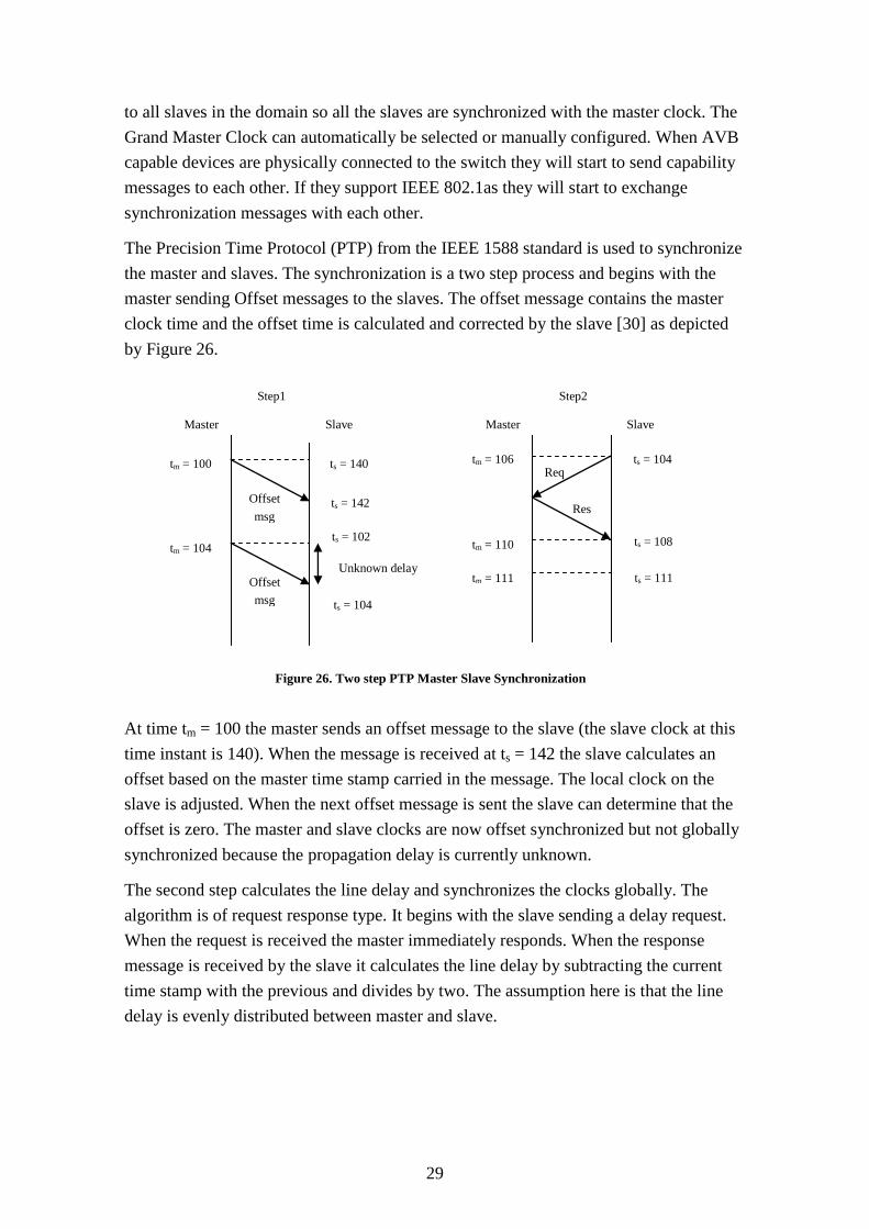
The Precision Time Protocol (PTP) from the IEEE 1588 standard is used to synchronize
the master and slaves. The synchronization is a two step process and begins with the
master sending Offset messages to the slaves. The offset message contains the master
clock time and the offset time is calculated and corrected by the slave [30] as depicted
by Figure 26.
At time tm = 100 the master sends an offset message to the slave (the slave clock at this
time instant is 140). When the message is received at ts = 142 the slave calculates an
offset based on the master time stamp carried in the message. The local clock on the
slave is adjusted. When the next offset message is sent the slave can determine that the
offset is zero. The master and slave clocks are now offset synchronized but not globally
synchronized because the propagation delay is currently unknown.
The second step calculates the line delay and synchronizes the clocks globally. The
algorithm is of request response type. It begins with the slave sending a delay request.
When the request is received the master immediately responds. When the response
message is received by the slave it calculates the line delay by subtracting the current
time stamp with the previous and divides by two. The assumption here is that the line
delay is evenly distributed between master and slave.
ts = 104
ts = 102
Res
Req
Offset
msg
Offset
msg
Master Slave
tm = 100 ts = 140
tm = 104
ts = 142
Unknown delay
Master Slave
Step1 Step2
tm = 106
tm = 110
tm = 111
ts = 104
ts = 108
ts = 111
Figure 26. Two step PTP Master Slave Synchronization
30
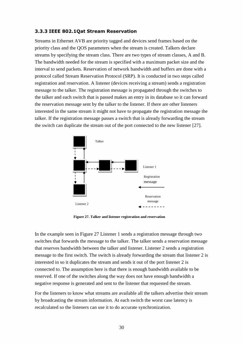
3.3.3 IEEE 802.1Qat Stream Reservation
Streams in Ethernet AVB are priority tagged and devices send frames based on the
priority class and the QOS parameters when the stream is created. Talkers declare
streams by specifying the stream class. There are two types of stream classes, A and B.
The bandwidth needed for the stream is specified with a maximum packet size and the
interval to send packets. Reservation of network bandwidth and buffers are done with a
protocol called Stream Reservation Protocol (SRP). It is conducted in two steps called
registration and reservation. A listener (devices receiving a stream) sends a registration
message to the talker. The registration message is propagated through the switches to
the talker and each switch that is passed makes an entry in its database so it can forward
the reservation message sent by the talker to the listener. If there are other listeners
interested in the same stream it might not have to propagate the registration message the
talker. If the registration message passes a switch that is already forwarding the stream
the switch can duplicate the stream out of the port connected to the new listener [27].
In the example seen in Figure 27 Listener 1 sends a registration message through two
switches that forwards the message to the talker. The talker sends a reservation message
that reserves bandwidth between the talker and listener. Listener 2 sends a registration
message to the first switch. The switch is already forwarding the stream that listener 2 is
interested in so it duplicates the stream and sends it out of the port listener 2 is
connected to. The assumption here is that there is enough bandwidth available to be
reserved. If one of the switches along the way does not have enough bandwidth a
negative response is generated and sent to the listener that requested the stream.
For the listeners to know what streams are available all the talkers advertise their stream
by broadcasting the stream information. At each switch the worst case latency is
recalculated so the listeners can use it to do accurate synchronization.
Registration
message
Reservation
message
Listener 1
Listener 2
Talker
Figure 27. Talker and listener registration and reservation
31
3.3.4 IEEE 802.1Qav Queuing and Forwarding
The stream classes A and B are mapped to two priority levels defined in IEEE 802.1Q.
The traffic shaping defined in the IEEE 802.Qav uses credit based shaping. The traffic
shaping creates a low upper limit on the size of the output buffers for the switches. This
creates a bounded delay for the streams in an AVB network and eliminates network
congestion [29].
Credit based shaping is similar to a token bucket algorithm. Credits increases as long as
there are packets in the queue and when packets are transmitted credits are withdrawn.
If the queue becomes empty the credits are cleared. The rate at which credits are
incremented is based on the amount of bandwidth that is allocated to a specific stream.
The credit based shaping is implemented for the AVB streams and for each traffic class
queue. For each stream queue the credit flow is based on the configured bandwidth
limit. The rate of credit flow for each traffic class is based on the sum of all bandwidth
limits for each stream associated with the specific traffic class.
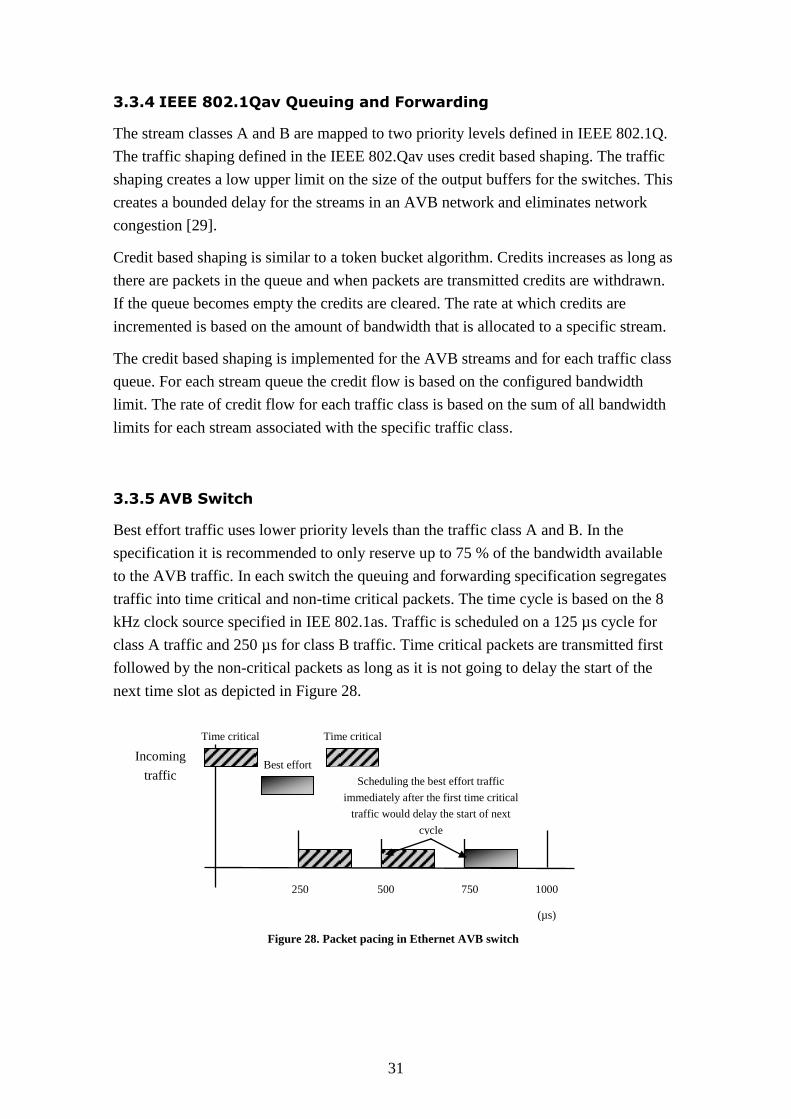
3.3.5 AVB Switch
Best effort traffic uses lower priority levels than the traffic class A and B. In the
specification it is recommended to only reserve up to 75 % of the bandwidth available
to the AVB traffic. In each switch the queuing and forwarding specification segregates
traffic into time critical and non-time critical packets. The time cycle is based on the 8
kHz clock source specified in IEE 802.1as. Traffic is scheduled on a 125 µs cycle for
class A traffic and 250 µs for class B traffic. Time critical packets are transmitted first
followed by the non-critical packets as long as it is not going to delay the start of the
next time slot as depicted in Figure 28.
Time critical Time critical
Best effort
Scheduling the best effort traffic
immediately after the first time critical
traffic would delay the start of next
cycle
250 500 750 1000
(µs)
Figure 28. Packet pacing in Ethernet AVB switch
Incoming
traffic
32
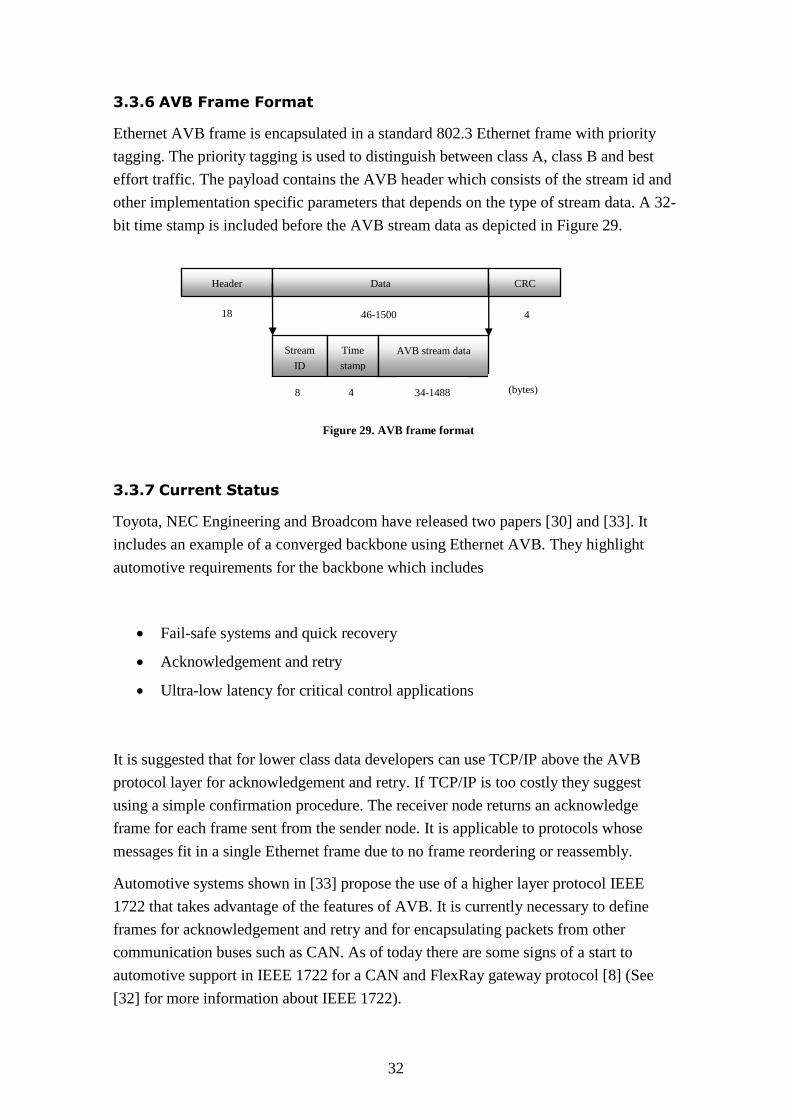
3.3.6 AVB Frame Format
Ethernet AVB frame is encapsulated in a standard 802.3 Ethernet frame with priority
tagging. The priority tagging is used to distinguish between class A, class B and best
effort traffic. The payload contains the AVB header which consists of the stream id and
other implementation specific parameters that depends on the type of stream data. A 32-
bit time stamp is included before the AVB stream data as depicted in Figure 29.
3.3.7 Current Status
Toyota, NEC Engineering and Broadcom have released two papers [30] and [33]. It
includes an example of a converged backbone using Ethernet AVB. They highlight
automotive requirements for the backbone which includes
Fail-safe systems and quick recovery
Acknowledgement and retry
Ultra-low latency for critical control applications
It is suggested that for lower class data developers can use TCP/IP above the AVB
protocol layer for acknowledgement and retry. If TCP/IP is too costly they suggest
using a simple confirmation procedure. The receiver node returns an acknowledge
frame for each frame sent from the sender node. It is applicable to protocols whose
messages fit in a single Ethernet frame due to no frame reordering or reassembly.
Automotive systems shown in [33] propose the use of a higher layer protocol IEEE
1722 that takes advantage of the features of AVB. It is currently necessary to define
frames for acknowledgement and retry and for encapsulating packets from other
communication buses such as CAN. As of today there are some signs of a start to
automotive support in IEEE 1722 for a CAN and FlexRay gateway protocol [8] (See
[32] for more information about IEEE 1722).
Header Data CRC
Stream
ID
Time
stamp
AVB stream data
4 46-1500 18
(bytes) 4 8 34-1488
Figure 29. AVB frame format
33
An article published in June 2011 [36] describes a 360-degree view system with
Ethernet. BMW together with Freescale produced a microcontroller that is used as a
gateway in a 360-degree camera system. The microcontroller has partial support for the
Ethernet AVB standard.
3.4 Summary of Analyzed Protocols
The three analyzed protocols can be categorized into two domains
Time-Triggered Communication
Rate constrained Communication
Rate constrained communication is supported by all of the solutions (AFDX,
TTEthernet and Ethernet AVB). The traffic shaping in Ethernet AVB is not based on a
periodic shaper but a credit based shaper.
TTEthernet advantage is that it supports time triggered, rate constrained and best effort
traffic. The time triggered communication allows fast control loops with minimal
latency and jitter because time triggered messages are sent over the network at
predefined times. A disadvantage with the time triggered communication is that it is less
flexible if changes are to be made to the nodes. If a node changes when messages are
sent the global time schedule uploaded to the switch needs to be changed. TTEthernet
does not specify a specific header for the time triggered traffic because it is sent in
special messages called protocol control frames. As a result you have less overhead for
time triggered traffic compared to the rate constrained AFDX protocol that uses IP and
UDP as headers.
A disadvantage for TTEthernet is that it requires a custom switch to support the time
triggered communication model and is currently only available from TTTech but it is
currently as of 2011 undergoing standardization and will be known as a SAE 6802.
When the standardization is finalized it is most likely that more manufacturers will
produce TTEthernet compliant switches and nodes. Future x-by-wire applications may
require high sampling rates above one KHz and strict deterministic behavior and for
such applications the time triggered solution is a good choice. TTEthernet has been
compared to FlexRay and the outcome was that it is a suitable replacement for an in-
vehicle network [24].
Both TTEthernet and AFDX support dual redundancy. The fault tolerant suggestion for
Ethernet AVB is a rapid spanning tree protocol which is more complex than using two
34
of everything. The latest suggestion for automotive adaptations for Ethernet AVB is to
use faster timers that can detected broken links and do recovery in less than 70 ms [30].
The AFDX rate constrained communication guarantees an upper bound on the
transmission latency. Bandwidth is predefined for the messages sent by all applications
but in comparison to time triggered communication it is not sent on a synchronized time
base. Rate constrained communication could be used as a high bandwidth Ethernet
backbone carrying message from sub buses such as CAN, LIN et cetera.
AFDX supports the rate constrained communication model and it is possible to do
evaluation and experiments using a low cost managed switch because it exploits the
MAC destination address in standard Ethernet as a way to route messages. Both AFDX
and TTEthernet are statically configured at design time and that is an advantage when it
is used as an in vehicle Ethernet backbone as they are normally closed systems. A
comparison between CAN, AFDX and FlexRay for ABS systems showed that AFDX
achieved identical performance compared to a FlexRay solution [19].
Ethernet AVB is developed by IEEE and has a potentially large customer base. It is
primarily marketed to the audio and video consumer/industry market however the
automotive industry has shown interest in the standard. The rate constrained model in
Ethernet AVB requires support in all switches along the route to support the dynamic
requests of streams and reserve bandwidth. Each switch knows about the streams that
flow through the switch. The request for a stream from a listener does not need to
propagate all the way to the sender if the stream is already transmitted through a switch
along the route. That might not be needed for an Ethernet backbone but can be
beneficial for an end user entertainment system.
Currently a subset of the AVB standard has seen use in a BMW camera system utilizing
the IEEE 802.1as which is used as a way to accurately synchronize the clocks [36].
The AFDX rate constrained traffic model is the most suitable protocol for Scania
adaptation if a low cost prototype should be implemented. Support for the virtual link
routing is possible with a smart switch.
The development process at Scania uses an iterative approach and would benefit from
adding new messages without large changes in the configuration. In that sense Ethernet
AVB would be the most suitable protocol due to the support of dynamically allocating
streams. On the other hand both Ethernet AVB and TTEthernet require special switch
support. If time triggered communication is wanted in the future a switch based on the
TTEthernet technology is easily deployed because it already supports the AFDX
standard. If care is taken at design time by allocating enough virtual links the AFDX
protocol can support introduction of new messages without large changes in the
configuration.
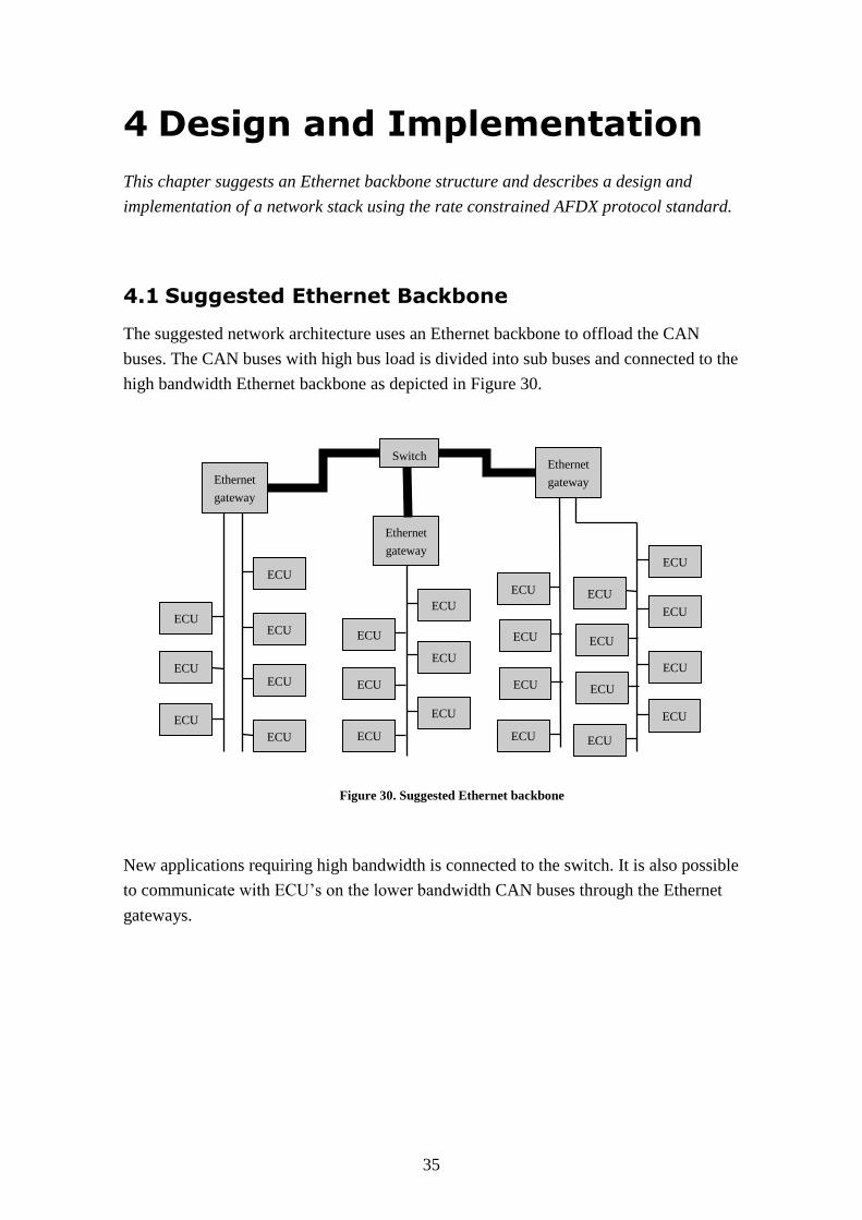
35
4 Design and Implementation
This chapter suggests an Ethernet backbone structure and describes a design and
implementation of a network stack using the rate constrained AFDX protocol standard.
4.1 Suggested Ethernet Backbone
The suggested network architecture uses an Ethernet backbone to offload the CAN
buses. The CAN buses with high bus load is divided into sub buses and connected to the
high bandwidth Ethernet backbone as depicted in Figure 30.
New applications requiring high bandwidth is connected to the switch. It is also possible
to communicate with ECU’s on the lower bandwidth CAN buses through the Ethernet
gateways.
Figure 30. Suggested Ethernet backbone
ECU
ECU ECU
ECU
ECU
ECU
ECU
ECU
ECU
ECU
ECU
ECU
ECU
ECU
ECU
ECU
ECU
ECU
ECU
ECU
ECU
ECU
ECU
ECU
ECU
Ethernet
gateway
Ethernet
gateway
Switch Ethernet
gateway
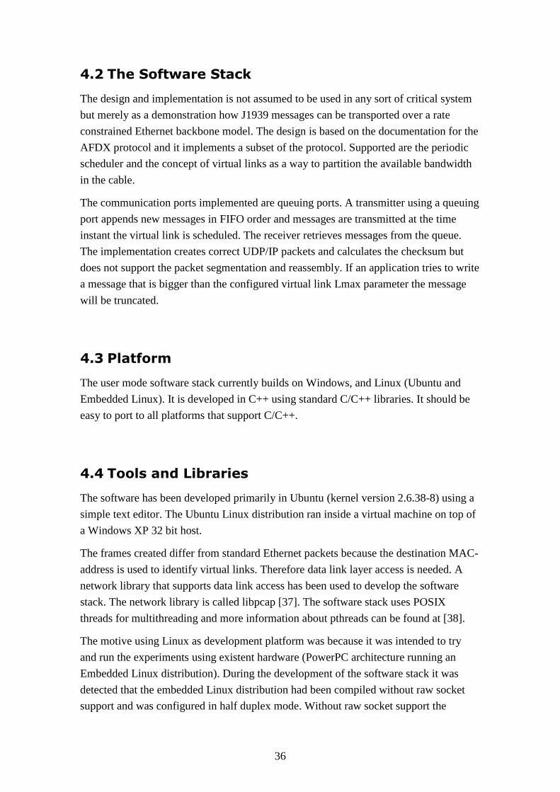
36
4.2 The Software Stack
The design and implementation is not assumed to be used in any sort of critical system
but merely as a demonstration how J1939 messages can be transported over a rate
constrained Ethernet backbone model. The design is based on the documentation for the
AFDX protocol and it implements a subset of the protocol. Supported are the periodic
scheduler and the concept of virtual links as a way to partition the available bandwidth
in the cable.
The communication ports implemented are queuing ports. A transmitter using a queuing
port appends new messages in FIFO order and messages are transmitted at the time
instant the virtual link is scheduled. The receiver retrieves messages from the queue.
The implementation creates correct UDP/IP packets and calculates the checksum but
does not support the packet segmentation and reassembly. If an application tries to write
a message that is bigger than the configured virtual link Lmax parameter the message
will be truncated.
4.3 Platform
The user mode software stack currently builds on Windows, and Linux (Ubuntu and
Embedded Linux). It is developed in C++ using standard C/C++ libraries. It should be
easy to port to all platforms that support C/C++.
4.4 Tools and Libraries
The software has been developed primarily in Ubuntu (kernel version 2.6.38-8) using a
simple text editor. The Ubuntu Linux distribution ran inside a virtual machine on top of
a Windows XP 32 bit host.
The frames created differ from standard Ethernet packets because the destination MAC-
address is used to identify virtual links. Therefore data link layer access is needed. A
network library that supports data link access has been used to develop the software
stack. The network library is called libpcap [37]. The software stack uses POSIX
threads for multithreading and more information about pthreads can be found at [38].
The motive using Linux as development platform was because it was intended to try
and run the experiments using existent hardware (PowerPC architecture running an
Embedded Linux distribution). During the development of the software stack it was
detected that the embedded Linux distribution had been compiled without raw socket
support and was configured in half duplex mode. Without raw socket support the
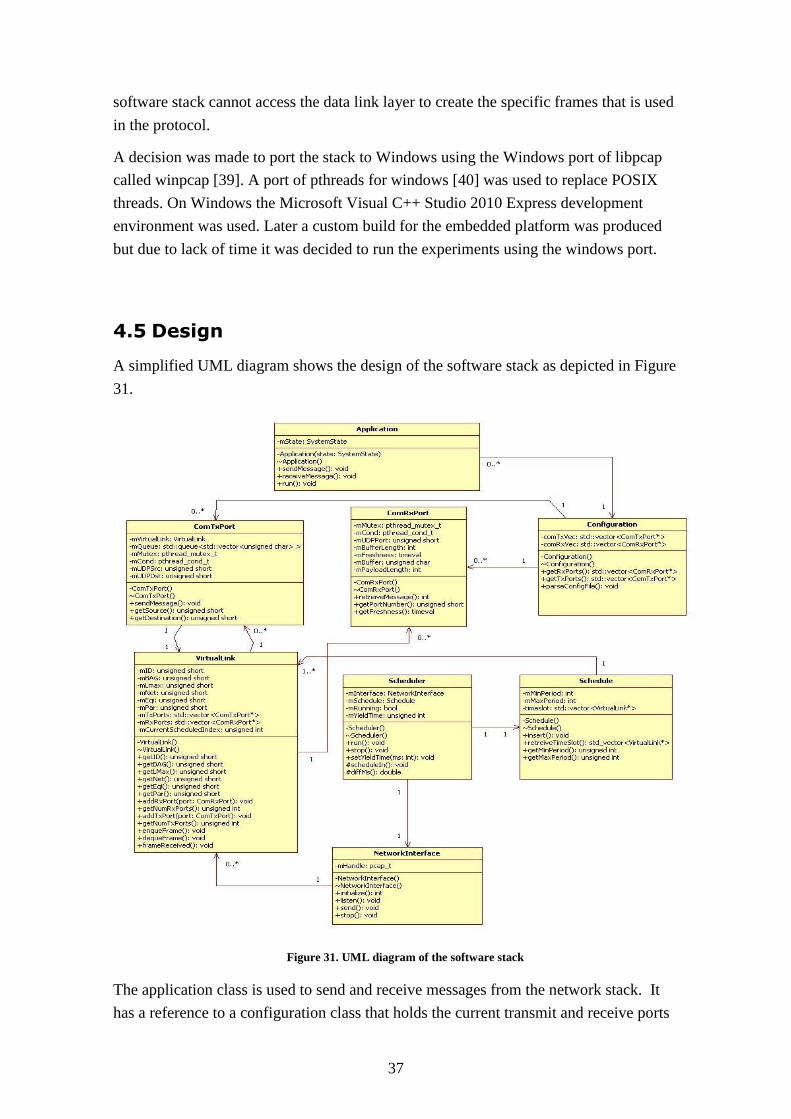
37
software stack cannot access the data link layer to create the specific frames that is used
in the protocol.
A decision was made to port the stack to Windows using the Windows port of libpcap
called winpcap [39]. A port of pthreads for windows [40] was used to replace POSIX
threads. On Windows the Microsoft Visual C++ Studio 2010 Express development
environment was used. Later a custom build for the embedded platform was produced
but due to lack of time it was decided to run the experiments using the windows port.
4.5 Design
A simplified UML diagram shows the design of the software stack as depicted in Figure
31.
Figure 31. UML diagram of the software stack
The application class is used to send and receive messages from the network stack. It
has a reference to a configuration class that holds the current transmit and receive ports
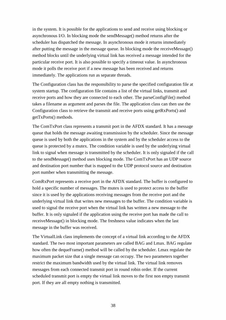
38
in the system. It is possible for the applications to send and receive using blocking or
asynchronous I/O. In blocking mode the sendMessage() method returns after the
scheduler has dispatched the message. In asynchronous mode it returns immediately
after putting the message in the message queue. In blocking mode the receiveMessage()
method blocks until the underlying virtual link has received a message intended for the
particular receive port. It is also possible to specify a timeout value. In asynchronous
mode it polls the receive port if a new message has been received and returns
immediately. The applications run as separate threads.
The Configuration class has the responsibility to parse the specified configuration file at
system startup. The configuration file contains a list of the virtual links, transmit and
receive ports and how they are connected to each other. The parseConfigFile() method
takes a filename as argument and parses the file. The application class can then use the
Configuration class to retrieve the transmit and receive ports using getRxPorts() and
getTxPorts() methods.
The ComTxPort class represents a transmit port in the AFDX standard. It has a message
queue that holds the message awaiting transmission by the scheduler. Since the message
queue is used by both the applications in the system and by the scheduler access to the
queue is protected by a mutex. The condition variable is used by the underlying virtual
link to signal when message is transmitted by the scheduler. It is only signaled if the call
to the sendMessage() method uses blocking mode. The ComTxPort has an UDP source
and destination port number that is mapped to the UDP protocol source and destination
port number when transmitting the message.
ComRxPort represents a receive port in the AFDX standard. The buffer is configured to
hold a specific number of messages. The mutex is used to protect access to the buffer
since it is used by the applications receiving messages from the receive port and the
underlying virtual link that writes new messages to the buffer. The condition variable is
used to signal the receive port when the virtual link has written a new message to the
buffer. It is only signaled if the application using the receive port has made the call to
receiveMessage() in blocking mode. The freshness value indicates when the last
message in the buffer was received.
The VirtualLink class implements the concept of a virtual link according to the AFDX
standard. The two most important parameters are called BAG and Lmax. BAG regulate
how often the dequeFrame() method will be called by the scheduler. Lmax regulate the
maximum packet size that a single message can occupy. The two parameters together
restrict the maximum bandwidth used by the virtual link. The virtual link removes
messages from each connected transmit port in round robin order. If the current
scheduled transmit port is empty the virtual link moves to the first non empty transmit
port. If they are all empty nothing is transmitted.
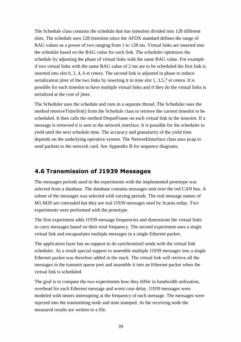
39
The Schedule class contains the schedule that has timeslots divided into 128 different
slots. The schedule uses 128 timeslots since the AFDX standard defines the range of
BAG values as a power of two ranging from 1 to 128 ms. Virtual links are inserted into
the schedule based on the BAG value for each link. The scheduler optimizes the
schedule by adjusting the phase of virtual links with the same BAG value. For example
if two virtual links with the same BAG value of 2 ms are to be scheduled the first link is
inserted into slot 0, 2, 4, 6 et cetera. The second link is adjusted in phase to reduce
serialization jitter of the two links by inserting it in time slot 1, 3,5,7 et cetera. It is
possible for each timeslot to have multiple virtual links and if they do the virtual links is
serialized at the cost of jitter.
The Scheduler uses the schedule and runs in a separate thread. The Scheduler uses the
method retreiveTimeSlot() from the Schedule class to retrieve the current timeslot to be
scheduled. It then calls the method DequeFrame on each virtual link in the timeslot. If a
message is retrieved it is sent to the network interface. It is possible for the scheduler to
yield until the next schedule time. The accuracy and granularity of the yield time
depends on the underlying operative system. The NetworkInterface class uses pcap to
send packets to the network card. See Appendix B for sequence diagrams.
4.6 Transmission of J1939 Messages
The messages periods used in the experiments with the implemented prototype was
selected from a database. The database contains messages sent over the red CAN bus. A
subset of the messages was selected with varying periods. The real message names of
M1-M20 are concealed but they are real J1939 messages used by Scania today. Two
experiments were performed with the prototype.
The first experiment adds J1939 message frequencies and dimensions the virtual links
to carry messages based on their total frequency. The second experiment uses a single
virtual link and encapsulates multiple messages in a single Ethernet packet.
The application layer has no support to do synchronized sends with the virtual link
scheduler. As a result special support to assemble multiple J1939 messages into a single
Ethernet packet was therefore added in the stack. The virtual link will retrieve all the
messages in the transmit queue port and assemble it into an Ethernet packet when the
virtual link is scheduled.
The goal is to compare the two experiments how they differ in bandwidth utilization,
overhead for each Ethernet message and worst case delay. J1939 messages were
modeled with timers interrupting at the frequency of each message. The messages were
injected into the transmitting node and time stamped. At the receiving node the
measured results are written to a file.
40
4.6.1 First Experiment Using Frequency Accumulation
The first experiment calculates virtual link BAG values by adding message frequencies.
See section 3.1.3 for an example. VL1 with a BAG value of 2 ms is calculated from
adding the frequencies for three messages with a period of 10 ms, VL2 from the four
messages with a period of 20 ms, VL3 from the the three messages with a period of 50
ms and VL4 from the messages with a period of 100, 1000 and 5000 ms. The CAN
message structure used has a 4 byte identifier and 8 bytes of data. The 4 byte identifier
is able to hold the 29 bit identifier. Consequently the Ethernet packet size is
Since the minimum Ethernet packet size is 64 bytes, 5 bytes of padding is used. The
message to virtual link mapping is depicted in Figure 32.
Figure 32. Message set mapping in first experiment
A queuing port is used for each message so VL1 has three ports connected to it, VL2
four, VL3 three and VL4 ten. The configuration file the sending node uses in the
experiment is depicted in Figure 33.
41
Figure 33. Configuration file for the first experiment
4.6.2 Second Experiment Using Message Encapsulation
The second experiment packs multiple messages into a single Ethernet packet. When
packing multiple J1939 messages into one Ethernet packet the Ethernet payload field
need at least a header to identify the number of J1939 messages that is sent in the
Ethernet packet. It is assumed each message has a fixed size. The BAG value for each
virtual link carrying multiple messages in a single packet needs to be smaller than the
message with the smallest period in the set.
If all the messages in the set are sent on a single virtual link the BAG value needs to be
set to less than 10 ms (the smallest period for a single message in the set). The Lmax
parameter is set to the worst case that could happen when all the messages have been
received between two scheduled transmissions of the virtual link. The allocated
bandwidth for the virtual link has to be large enough to hold all the messages in a single
Ethernet packet. A small header is used to indicate the number of messages packed in
the Ethernet packet. The J1939 message structure is 12 bytes and the selected message
set contains 20 messages so the Lmax parameter is set to
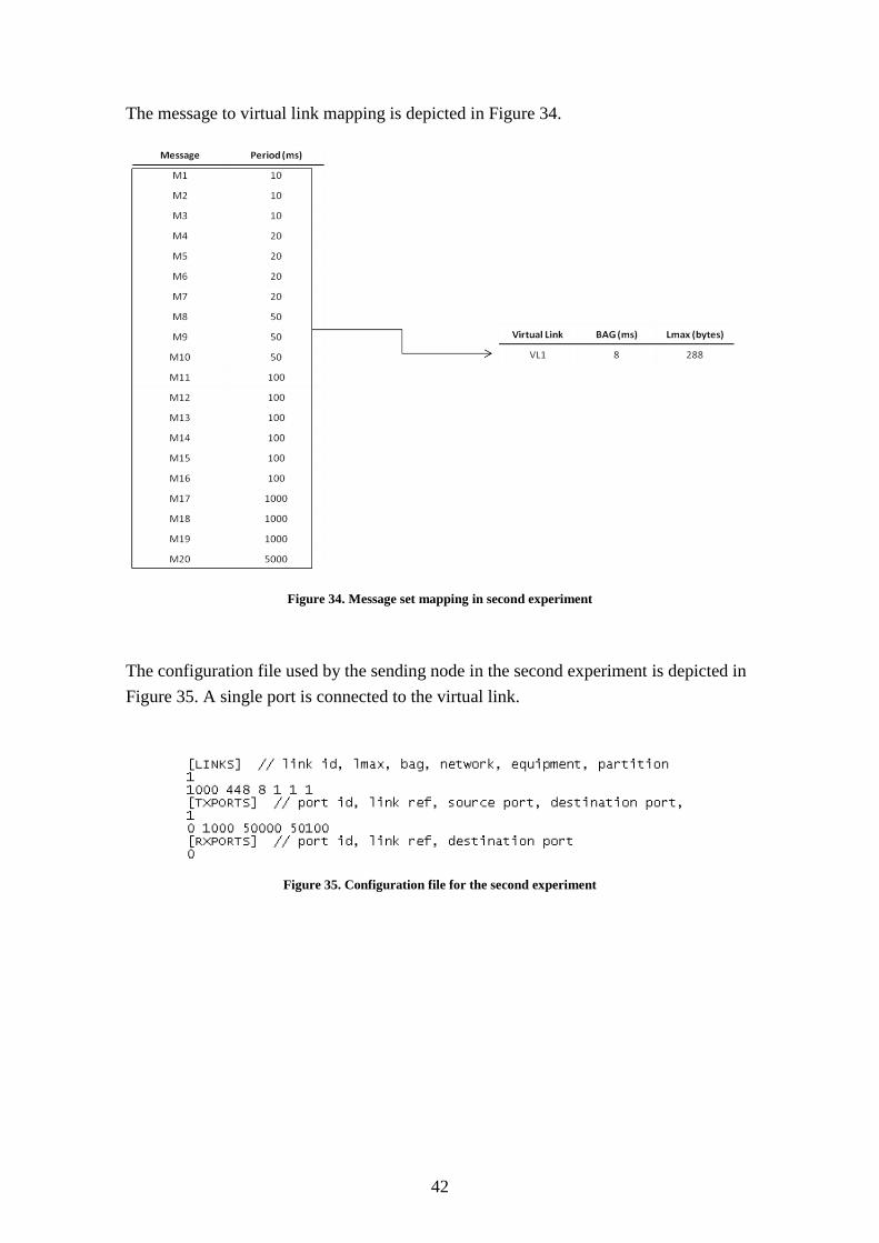
42
The message to virtual link mapping is depicted in Figure 34.
Figure 34. Message set mapping in second experiment
The configuration file used by the sending node in the second experiment is depicted in
Figure 35. A single port is connected to the virtual link.
Figure 35. Configuration file for the second experiment
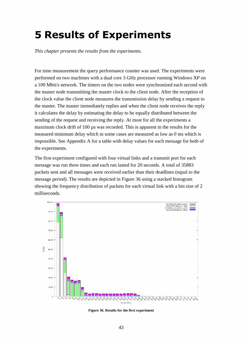
43
5 Results of Experiments
This chapter presents the results from the experiments.
For time measurement the query performance counter was used. The experiments were
performed on two machines with a dual core 3 GHz processor running Windows XP on
a 100 Mbit/s network. The timers on the two nodes were synchronized each second with
the master node transmitting the master clock to the client node. After the reception of
the clock value the client node measures the transmission delay by sending a request to
the master. The master immediately replies and when the client node receives the reply
it calculates the delay by estimating the delay to be equally distributed between the
sending of the request and receiving the reply. At most for all the experiments a
maximum clock drift of 100 µs was recorded. This is apparent in the results for the
measured minimum delay which in some cases are measured as low as 0 ms which is
impossible. See Appendix A for a table with delay values for each message for both of
the experiments.
The first experiment configured with four virtual links and a transmit port for each
message was run three times and each run lasted for 20 seconds. A total of 35883
packets sent and all messages were received earlier than their deadlines (equal to the
message period). The results are depicted in Figure 36 using a stacked histogram
showing the frequency distribution of packets for each virtual link with a bin size of 2
milliseconds.
Figure 36. Results for the first experiment
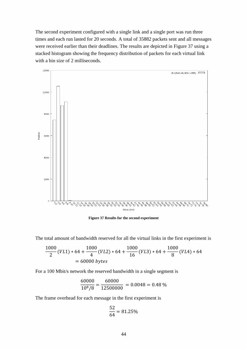
44
The second experiment configured with a single link and a single port was run three
times and each run lasted for 20 seconds. A total of 35882 packets sent and all messages
were received earlier than their deadlines. The results are depicted in Figure 37 using a
stacked histogram showing the frequency distribution of packets for each virtual link
with a bin size of 2 milliseconds.
Figure 37 Results for the second experiment
The total amount of bandwidth reserved for all the virtual links in the first experiment is
For a 100 Mbit/s network the reserved bandwidth in a single segment is
The frame overhead for each message in the first experiment is

45
Most of the packets in VL1 is sent and received within 2 milliseconds. The distribution
of packets for VL2, VL3 and VL4 are in general equal.
The total amount of bandwidth reserved for the virtual link in the second experiment is
For a 100 Mbit/s network the reserved bandwidth in a single segment is
For the second experiment the average number of messages encapsulated in a single
Ethernet transmission was also measured. The result showed that on average five
messages were transmitted. For a virtual link with the Lmax parameter set to 288 bytes
only
of the virtual link capacity is used.
The second experiment has almost the same overhead (one byte difference due to the
extra one byte header) for the worst case if a single message is transmitted. On average
when approximately 5 packets are sent the overhead is
In the best case if all 20 messages are pending transmission
Since all the messages are sent in a single virtual link the worst case latencies are
similar for all messages.
Even if all messages for the two experiments were received before their deadline
(deadline equal to message period) it should be noted that the experiments was run on a
non real-time operating system. The virtual link scheduler in the experiments tries to
use as little processor time as possible and yields the remaining time until the next
scheduling time. Due to limitations in sleep granularity and context switches some
messages carried by VL1 and VL2 in the first experiment exceed the theoretical
maximum delay which is
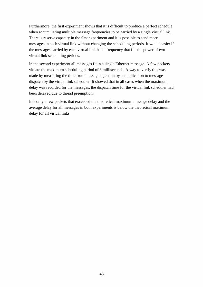
46
Furthermore, the first experiment shows that it is difficult to produce a perfect schedule
when accumulating multiple message frequencies to be carried by a single virtual link.
There is reserve capacity in the first experiment and it is possible to send more
messages in each virtual link without changing the scheduling periods. It would easier if
the messages carried by each virtual link had a frequency that fits the power of two
virtual link scheduling periods.
In the second experiment all messages fit in a single Ethernet message. A few packets
violate the maximum scheduling period of 8 milliseconds. A way to verify this was
made by measuring the time from message injection by an application to message
dispatch by the virtual link scheduler. It showed that in all cases when the maximum
delay was recorded for the messages, the dispatch time for the virtual link scheduler had
been delayed due to thread preemption.
It is only a few packets that exceeded the theoretical maximum message delay and the
average delay for all messages in both experiments is below the theoretical maximum
delay for all virtual links
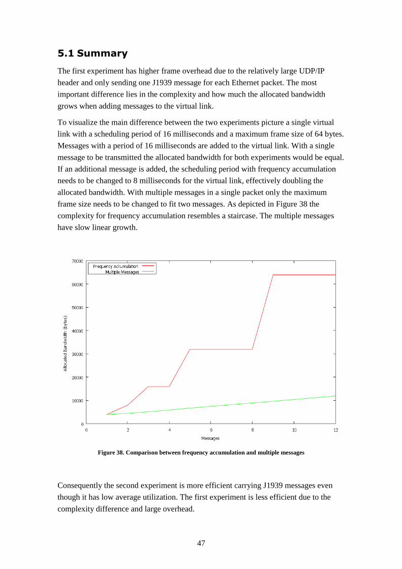
47
5.1 Summary
The first experiment has higher frame overhead due to the relatively large UDP/IP
header and only sending one J1939 message for each Ethernet packet. The most
important difference lies in the complexity and how much the allocated bandwidth
grows when adding messages to the virtual link.
To visualize the main difference between the two experiments picture a single virtual
link with a scheduling period of 16 milliseconds and a maximum frame size of 64 bytes.
Messages with a period of 16 milliseconds are added to the virtual link. With a single
message to be transmitted the allocated bandwidth for both experiments would be equal.
If an additional message is added, the scheduling period with frequency accumulation
needs to be changed to 8 milliseconds for the virtual link, effectively doubling the
allocated bandwidth. With multiple messages in a single packet only the maximum
frame size needs to be changed to fit two messages. As depicted in Figure 38 the
complexity for frequency accumulation resembles a staircase. The multiple messages
have slow linear growth.
Figure 38. Comparison between frequency accumulation and multiple messages
Consequently the second experiment is more efficient carrying J1939 messages even
though it has low average utilization. The first experiment is less efficient due to the
complexity difference and large overhead.
48
6 Discussion
This chapter discusses how to provide support for incremental updates, software and
message compatibility, reducing overhead and improvements that can be made to the
prototype developed.
6.1 Incremental Updates
Incremental updates are possible with the proposed protocol if care is taken at design
and planning stage. By allocating reserve capacity in the virtual links it is possible to
add new messages sent from an ECU without updating the virtual link schedules in the
transmitting/receiving ECU’s and switch.
6.2 Software and Message Compatibility
One way of providing backward compatibility for messages carried over an Ethernet
solution is to use some form of serialization format. Protocol buffers are Google’s
approach to provide a serialization format and it is described in a similar way as XML.
The messages are defined in .proto files.
message ether_message{
required int32 id = 1;
optional int32 a = 2;
optional int32 b = 3;
optional string description = 4;
}
Messages have one or more uniquely numbered fields, each field has a name and a
value type. There are three types of fields required, optional and repeated. A reader
expects the required field to be in the message otherwise it is deemed incomplete. The
optional field is not required and the reader parses the message correctly even if it is not
supplied. The repeated field can be repeated any number of times including zero. The
.proto file is compiled to C++ code and can be used by application developers in the
following way

49
ether_message msg;
msg.set_id(1234);
msg.set_a(5);
msg.set_b(6);
msg.set_description(”ether_message”);
msg.serializeToStream(&output);
To use it with the rate constrained software stack the serialized stream is then sent to a
transmit port. If an existing message type no longer meets the requirement it can be
extended by adding additional fields. Code created with the old format is still compa-
tible with the new format apart from that it is ignoring the additional fields in the
message. It is therefore possible for an old device running applications using the old
format to communicate with newer applications using the new format. As a result old
software in ECU’s are able to communicate using the old message format with newer
ECU’s using the new message format. For more information about Google protocol
buffers see [41].
6.3 Reducing Overhead
The AFDX protocol uses a UDP/IP header but a simple closed backbone with a single
switch could use a smaller header which reduces the amount of overhead for each
packet. The header may possibly be small enough so the network stack can differentiate
between messages intended for different ports. Implementing such a design could be
done using the MAC destination address and the priority field of an 802.1Q Ethernet
frame to distinguish between time critical and best effort traffic in similar way as
TTEthernet and Ethernet AVB. The time critical traffic could then use the smaller
header. Another alternative is to use larger messages by converging functionality and
sending more information in larger packets.
6.4 Improvements to the Prototype
An implementation of the sampling port type needs to be done. The scheduler for the
virtual link can be used to trigger callbacks for the application layer. Applications
would be scheduled at the same time instant as the virtual link and could send messages
synchronized with the regulator.
The virtual link scheduler in the experiments tries to use as little processor time as
possible and yields the remaining time until the next scheduling time. The Windows XP
scheduler puts the network scheduler thread in a wait state when it yields. Due to
50
limitations in the sleep granularity and context switches the time it takes for the thread
to wake up is nondeterministic. To get better results from the network scheduler the
protocol stack should be implemented in a real-time operating system.

51
7 Conclusion
CAN is reaching its limits when it comes to bandwidth. In the future more bandwidth is
needed and new features require more bandwidth. Ethernet is an interesting technology
to use as a way to solve the problem.
First three Ethernet real-time protocols were studied. The three studied protocols were
AFDX, TTEthernet and Ethernet AVB.
Thereafter, a prototype was designed and implemented. The prototype was based on the
AFDX protocol because it is the most suitable protocol for Scania adaptation if a low
cost prototype should be implemented. Support for the virtual link routing is possible
with a standard smart switch. The other protocols require dedicated switch hardware.
The prototype was evaluated in two experiments. Both experiments transmit J1939
messages over a simulated Ethernet backbone. The first experiment uses frequency
accumulation to parameterize the virtual links. The second experiment tries to pack
multiple J1939 messages in a single Ethernet packet.
The results of the experiments were that the second experiment is the most efficient.
The first experiment has higher frame overhead due to the relatively large UDP/IP
header and only sending one J1939 message for every Ethernet packet. The most
important difference lies in the complexity and how much the allocated bandwidth
grows when adding messages to the virtual link.
The development process at Scania uses an iterative approach and would benefit from
adding new messages without large changes in the configuration. In that sense Ethernet
AVB would be the most suitable protocol due to the support of dynamically allocating
streams. On the other hand both Ethernet AVB and TTEthernet require special switch
support. If time triggered communication is wanted in the future a switch based on the
TTEthernet technology is easily deployed because it already supports the AFDX
standard. If care is taken at design time by allocating enough virtual links the AFDX
protocol can support introduction of new messages without large changes in the
configuration.
To improve performance the stack should be implemented using a real-time operating
system and put in the driver layer. Moving the virtual link scheduler to a separate
hardware implementation is even better although that is obviously a cost concern. It has
been observed that in the current CAN network it is difficult to get an accurate
estimation of the bus load. The benefit of a rate constrained Ethernet model is that the
total amount of allocated capacity can be calculated offline. Another benefit is that if an
application tries to push more data than allocated for by the virtual link it will not
degrade the whole network but it is isolated to the virtual link.
52
Ethernet in a real-time vehicle network is a viable solution. With full duplex there is no
access arbitration to the medium. The prototype implemented in this degree project uses
a rate constrained traffic model and removes the remaining problem with uncertain
buffer contention. As a result the prototype can be used a starting point for a future
Ethernet backbone.
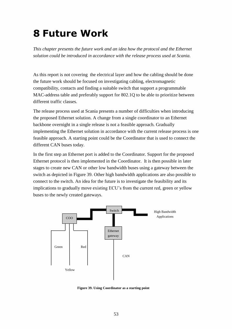
53
8 Future Work
This chapter presents the future work and an idea how the protocol and the Ethernet
solution could be introduced in accordance with the release process used at Scania.
As this report is not covering the electrical layer and how the cabling should be done
the future work should be focused on investigating cabling, electromagnetic
compatibility, contacts and finding a suitable switch that support a programmable
MAC-address table and preferably support for 802.1Q to be able to prioritize between
different traffic classes.
The release process used at Scania presents a number of difficulties when introducing
the proposed Ethernet solution. A change from a single coordinator to an Ethernet
backbone overnight in a single release is not a feasible approach. Gradually
implementing the Ethernet solution in accordance with the current release process is one
feasible approach. A starting point could be the Coordinator that is used to connect the
different CAN buses today.
In the first step an Ethernet port is added to the Coordinator. Support for the proposed
Ethernet protocol is then implemented in the Coordinator. It is then possible in later
stages to create new CAN or other low bandwidth buses using a gateway between the
switch as depicted in Figure 39. Other high bandwidth applications are also possible to
connect to the switch. An idea for the future is to investigate the feasibility and its
implications to gradually move existing ECU’s from the current red, green or yellow
buses to the newly created gateways.
Yellow
Red Green
Ethernet
gateway
Switch
COO
CAN
High Bandwidth
Applications
Figure 39. Using Coordinator as a starting point

54
References
[1] Jane W. S. Liu, "Real-Time System", Prentice Hall; 1 edition, 2000,
ISBN 0130996513
[2] LAN/MAN Standards Committee of the IEEE Computer Society, "IEEE Std 802.3-2008, Section 3", IEEE
802.3 Protocol Specifications, 2008,
http://standards.ieee.org/getieee802/download/802.3-2008_section3.pdf
[Accessed 2011-08-10]
[3] LAN/MAN Standards Committee of the IEEE Computer Society, "Part 3: Carrier Sense Multiple Access with
Collision Detection (CSMA/CD) Access Method and Physical Layer Specifications", IEEE 802.3ba Protocol
Specifications, 2010,
http://standards.ieee.org/getieee802/download/802.3ba-2010.pdf
[Accessed 2011-08-10]
[4] LAN MAN Standards Committee of the IEEE Computer Society, "IEEE Standard for Local and metropolitan
area networks—Virtual Bridged Local Area Network", IEEE 802.1Q Protocol Specifications, 2005,
http://standards.ieee.org/getieee802/download/802.1Q-2005.pdf
[Accessed 2011-09-01]
[5] ISO Committee, "Road vehicles – Controller area network (CAN) – part 1: Data link layer and physical
signaling", ISO-11898-1, 2003,
http://www.iso.org/iso/iso_catalogue/catalogue_tc/catalogue_detail.htm?csnumber=44158
[Accessed 2011-07-05]
[6] Thomas Nolte, Hans Hansson, Christer Norström, Sasikumar Punnekkat, "Using bit-stuffing distributions in
CAN analysis", IEEE Real-Time Embedded Systems Workshop, 2001,
http://www.mrtc.mdh.se/publications/0351.pdf
[Accessed 2011-05-16]
[7] SAE International, "Surface Vehicle Recommended Practice", SAE J1939-21, 2006,
http://standards.sae.org/j1939/21_200612/
[Accessed 2011-04-14]
[8] SAE International, "Surface Vehicle Standard", SAE J1939-71, 2011,
http://standards.sae.org/j1939/71_201103/
[Accessed 2011-04-20]
[9] Paula Doyle, "Introduction to Real-Time Ethernet 1", The Extension Volume 5 issue 3, 2004,
http://www.datalinkcom.net/Real%20Time%20Ethernet1.pdf
[Accessed 2011-05-10]
[10] Cisco (White Paper), "Cut-Through and Store-and-Forward Ethernet Switching for Low-Latency
Environments", 2008,
http://www.cisco.com/en/US/prod/collateral/switches/ps9441/ps9670/white_paper_c11-465436.pdf
[Accessed 2011-05-11]
[11] Charles m. Kozierok, "The TCP/IP Guide", No Starch Press, 2005,
ISBN 159327047X
55
[12] GE Fanuc Embedded Systems, "AFDX/ARINC 664 Protocol Tutorial", 2007,
http://www.systerra.de/documents/AFDX_Tutorial_WP.pdf
[Accessed 2011-04-02]
[13] Detlev Schaadt (White Paper), "AFDX/ARINC 664 Concept, Design, Implementation and Beyond", SYSGO
Embedding Innovations, 2007,
http://www.cems.uwe.ac.uk/~ngunton/afdx_arinc664.pdf
[Accessed 2011-04-03]
[14] Condor Engineering (PDF), "AFDX Protocol Tutorial", 2005,
http://www.cems.uwe.ac.uk/~ngunton/afdx_detailed.pdf
[Accessed 2011-04-28]
[15] TechSAT GmbH (PDF), "AFDX/ARINC664 Tutorial", 2008,
http://www.techsat.com/fileadmin/media/pdf/infokiosk/TechSAT_TUT-AFDX-EN.pdf
[Accessed 2011-05-18]
[16] "AFDX Product Solutions",
http://www.afdx.com
[Accessed 2011-06-28]
[17] Richard L. Alena (PDF), "Communications for Integrated Modular Avionics", SBS Technologies, 2007,
http://ti.arc.nasa.gov/m/pub-archive/1277h/1277%20%28Alena%29.pdf
[Accessed 2011-06-09]
[18] Bob Pickles (PDF), "Avionics Full Duplex Switched Ethernet", 2006,
http://www.sierrasales.com/pdfs/AFDX_Overview.pdf
[Accessed 2011-05-09]
[19] Horst Satzwedel, "Comparison of CAN, FlexRay, and Ethernet, Architectures for the Design of ABS Systems",
SAE 2011 World Congress & Exhibition, April 2011,
http://papers.sae.org/2011-01-0453/
[Accessed 2011-05-25]
[20] TTTech (PDF), "Scalable Real-Time Ethernet Platform", TTTech Computertechnik AG, 2009,
http://www.ttagroup.org/ttethernet/doc/TTEthernet_Article.pdf
[Accessed 2011-07-05]
[21] Ken Bisson, (White Paper)" SAE AS6802 Deterministic Ethernet Network Solution Avionics Interface
Technologies", Avionics Interface Technologies, 2011,
http://www.aviftech.com/igsbase/igstemplate.cfm/SRC=MD005/SRCN=index/GnavID=5/SnavID=26
[Accessed 2011-07-01]
[22] Wilfried Steiner, Günther Bauer, Brendan Hall, Michael Paulitsch, Srivatsan Varadarajan, "TTEthernet
Dataflow Concept", IEEE International Symposium on Network Computing and Applications, 2009,
http://ieeexplore.ieee.org/xpl/freeabs_all.jsp?arnumber=5190394
[Accessed 2011-06-15]
[23] Till Steinbach, H. Dieumo Kenfack, Franz Korf, Thomas C. Schmidt (PDF), "An Extension of the OMNeT++
INET Framework for Simulating Real-time Ethernet with High Accuracy - 4th international OMNeT++
Workshop", Hamburg University of Applied Sciences, 2011-03-20,
http://www.omnet-workshop.org/2011/uploads/slides/OMNeT_WS2011_S1_P3_Steinbach.pdf
[Accessed 2011-07-10]
56
[24] Till Steinbach, Franz Korf, Thomas C. Smidt (PDF), "Comparing Time-Triggered Ethernet with FlexRay: An
Evaluation of Competing Approaches to Real-time for In-Vehicle Networks", Hamburg University of Applied
Sciences, 2010-05-20,
http://inet.cpt.haw-hamburg.de/events/slides/FlexRay_TTEthernet_Slides.pdf
[Accessed 2011-06-10]
[25] TTTech (PDF), "NASA's Orion Crew Exploration Vehicle Systems Integration with TTEthernet", TTTech
Computertechnik AG, 2009,
http://www.tttech.com/fileadmin/content/pdf/TTTech-NASA-Casestudy-Orion.pdf
[Accessed 2011-05-10]
[26] Wilfried Steiner, Günther Bauer, David Jameux (PDF), "ETHERNET FOR SPACE APPLICATIONS:
TTEthernet", European Space Agency ESTEC, 2008,
http://2008.spacewire-conference.org/downloads/Papers/Networks%20&%20Protocols%202/Steiner.pdf
[Accessed 2011-05-20]
[27] Mike Jones (White Paper), "Ethernet Driving down Automotive Cost of Ownership: Investigating the emergence
of Ethernet in Automotive Applications", Micrel Inc, 2009,
http://www.micrel.com/applications/auto/AutomotiveEthernet_WP.pdf
[Accessed 2011-06-10]
[28] Rick Kreifeldt (White Paper), "AVB for Automotive Use", AVnu Alliance, 2009,
http://www.avnu.org/files/static_page_files/AADD34CC-1D09-3519-AD2D3D331F524CF6/AVnu
Automotive__White Paper.pdf
[Accessed 2011-05-20]
[29] Michael Johas Teener (White Paper), "No-excuses Audio/Video Network: the Technology Behind", AVnu
Alliance, 2009,
http://www.meyersound.com/pdf/products/d-mitri/NoExcuses_AudioVideoNetworking_highres.pdf
[Accessed 2011-04-10]
[30] Yong Kim, Masa Nakamura (PDF), "Automotive Ethernet Network Requirements", IEEE 802.1 AVB Task
Force Meeting, 2011,
http://www.ieee802.org/1/files/public/docs2011/new-avb-KimNakamura-automotive-network-requirements-
0311.pdf
[Accessed 2011-06-18]
[31] BMW Group (PDF), "1722.1 Automotive Use Cases: 802.1 AVB in a vehicular environment", BMW Group
Technology Office, 2009,
http://grouper.ieee.org/groups/1722/1/contributions/1722.1-busch_automotive_use_cases_1209-v1.pdf
[Accessed 2011-05-10]
[32] IEEE 1722 Working Group, "IEEE 1722 - Layer 2 Transport Protocol Working Group",
http://grouper.ieee.org/groups/1722
[Accessed 2011-08-02]
[33] Junichi Takeuchi (White Paper), "Requirements for Automotive AVB Systems Profiles", 2011,
http://www.avnu.org/files/static_page_files/9F0A4E3F-1D09-3519-ADBA4F0C747D7640/Contributed
Automotive Whitepaper_April 2011.pdf
[Accessed 2011-04-02]
[34] Dave Olsen (PDF), "IEEE 1722a Assumptions", IEEE 1722 Berkeley CA, 2011
http://grouper.ieee.org/groups/1722/contributions/1722a-dolsen-Assumptions-v5.pdf
[Accessed 2011-08-15]

57
[35] Dr. Robert Bruckmeier (PDF), "Usage of Ethernet in the Automotive Environment", Freescale Technology
Forum Orlando, 2010,
http://www.freescale.com/files/ftf_2010/Americas/WBNR_FTF10_AUT_F0558.pdf
[Accessed 2011-05-11]
[36] "Freescale & BMW cooperate on 360º parking assist systems", Electronics Vertical Intelligence,
http://evertiq.com/news/19834
[Accessed 2011-06-25]
[37] "TCPDUMP & Libpcap"
http://www.tcpdump.org
[Accessed 2011-08-01]
[38] "POSIX thread (pthread) libraries"
http://www.yolinux.com/TUTORIALS/LinuxTutorialPosixThreads.html
[Accessed 2011-08-10]
[39] "WinPcap The industry-standard windows packet capture library",
http://www.winpcap.org
[Accessed 2011-08-08]
[40] "Open Source POSIX Threads for Win32",
http://sourceware.org/pthreads-win32
[Accessed 2011-08-12]
[41] "Google Protocol Buffers",
http://code.google.com/intl/sv/apis/protocolbuffers/docs/proto.html
[Accessed 2011-08-30]
[42] ISO Standard, "Road vehicles – Diagnostic communication over Internet Protocol (DoIP) – Part 1: General
information and use case definition", ISO 13400-1, 2011,
http://www.iso.org/iso/iso_catalogue/catalogue_tc/catalogue_detail.htm?csnumber=53765 .
[Accessed 2011-09-01]
[43] "FlexRay the communication system for advanced automotive control applications",
http://www.flexray.com
[Accessed 2011-09-10]

58
Appendix A Delay tables
Message Period (ms) Minimum
delay(s)
Maximum
delay(s)
Average
delay(s)
Packets sent
M1 10 0.000015 0.009399 0.003727 5582
M2 10 0.000015 0.009384 0.001444 5584
M3 10 0.000816 0.008430 0.002460 5584
M4 20 0.000015 0.017632 0.005636 2927
M5 20 0.000015 0.017639 0.007820 2929
M6 20 0.000015 0.017639 0.007589 2932
M7 20 0.000023 0.019250 0.008016 2935
M8 50 0.000046 0.016754 0.007473 1186
M9 50 0.010834 0.032875 0.022813 1187
M10 50 0.002975 0.048004 0.038737 1189
M11 100 0.000053 0.074348 0.022688 601
M12 100 0.000046 0.077301 0.018578 603
M13 100 0.000046 0.064606 0.018296 605
M14 100 0.004913 0.072418 0.025909 607
M15 100 0.000053 0.055809 0.023944 609
M16 100 0.005997 0.063622 0.030900 610
M17 1000 0.000031 0.055809 0.014037 63
M18 1000 0.003937 0.063522 0.021552 66
M19 1000 0.000053 0.070374 0.025651 69
M20 5000 0.006981 0.078239 0.040363 15
Results from first experiment
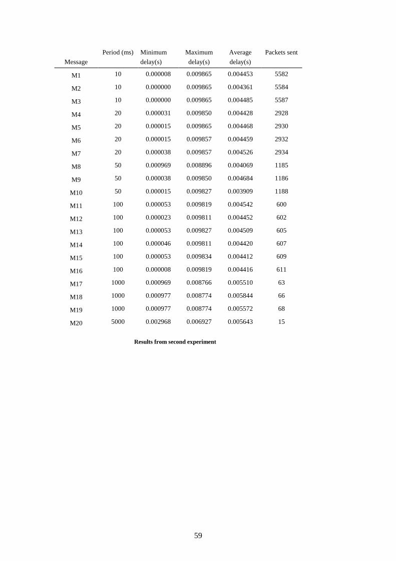
59
Message
Period (ms) Minimum
delay(s)
Maximum
delay(s)
Average
delay(s)
Packets sent
M1 10 0.000008 0.009865 0.004453 5582
M2 10 0.000000 0.009865 0.004361 5584
M3 10 0.000000 0.009865 0.004485 5587
M4 20 0.000031 0.009850 0.004428 2928
M5 20 0.000015 0.009865 0.004468 2930
M6 20 0.000015 0.009857 0.004459 2932
M7 20 0.000038 0.009857 0.004526 2934
M8 50 0.000969 0.008896 0.004069 1185
M9 50 0.000038 0.009850 0.004684 1186
M10 50 0.000015 0.009827 0.003909 1188
M11 100 0.000053 0.009819 0.004542 600
M12 100 0.000023 0.009811 0.004452 602
M13 100 0.000053 0.009827 0.004509 605
M14 100 0.000046 0.009811 0.004420 607
M15 100 0.000053 0.009834 0.004412 609
M16 100 0.000008 0.009819 0.004416 611
M17 1000 0.000969 0.008766 0.005510 63
M18 1000 0.000977 0.008774 0.005844 66
M19 1000 0.000977 0.008774 0.005572 68
M20 5000 0.002968 0.006927 0.005643 15
Results from second experiment
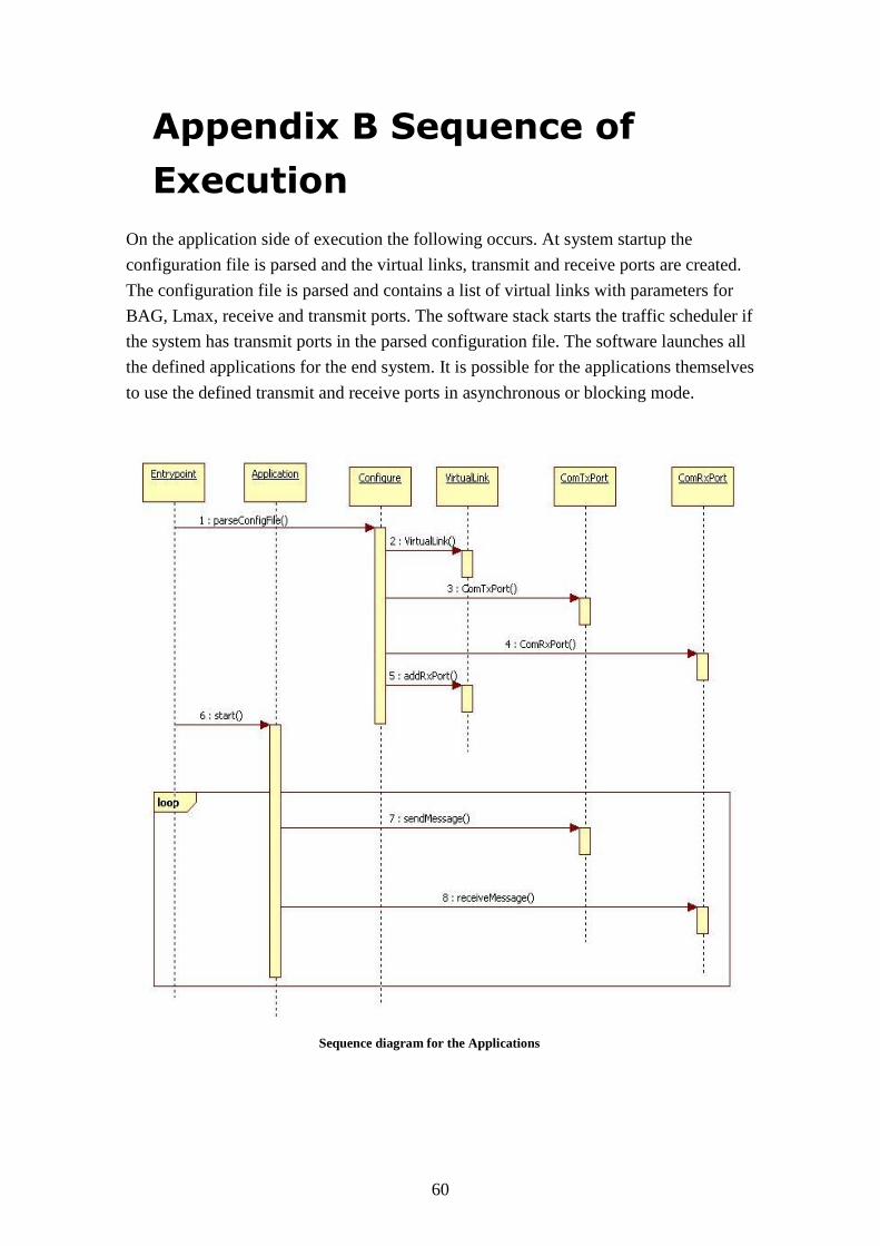
60
Appendix B Sequence of
Execution
On the application side of execution the following occurs. At system startup the
configuration file is parsed and the virtual links, transmit and receive ports are created.
The configuration file is parsed and contains a list of virtual links with parameters for
BAG, Lmax, receive and transmit ports. The software stack starts the traffic scheduler if
the system has transmit ports in the parsed configuration file. The software launches all
the defined applications for the end system. It is possible for the applications themselves
to use the defined transmit and receive ports in asynchronous or blocking mode.
Sequence diagram for the Applications

61
On the Scheduler side of execution the following occurs. Virtual links are inserted into
the schedule based on the BAG value for each link. The scheduler runs in a separate
thread and retrieves the current scheduled timeslot. If there are multiple virtual links in
the current timeslot they are serialized. It is possible for each virtual link to have
multiple transmitting ports. The transmit ports are scheduled in round robin order. The
scheduler retrieves the packet and sends it to the network interface.
Sequence diagram for the scheduler
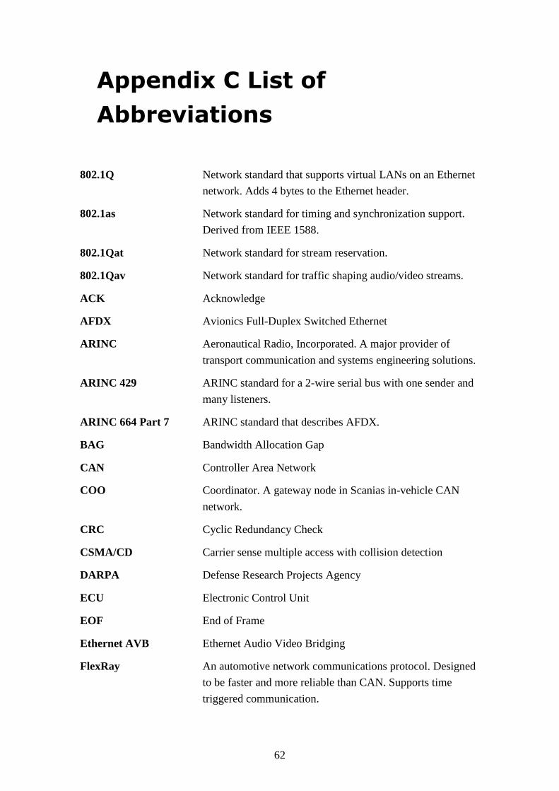
62
Appendix C List of
Abbreviations
802.1Q Network standard that supports virtual LANs on an Ethernet
network. Adds 4 bytes to the Ethernet header.
802.1as Network standard for timing and synchronization support.
Derived from IEEE 1588.
802.1Qat Network standard for stream reservation.
802.1Qav Network standard for traffic shaping audio/video streams.
ACK Acknowledge
AFDX Avionics Full-Duplex Switched Ethernet
ARINC Aeronautical Radio, Incorporated. A major provider of
transport communication and systems engineering solutions.
ARINC 429 ARINC standard for a 2-wire serial bus with one sender and
many listeners.
ARINC 664 Part 7 ARINC standard that describes AFDX.
BAG Bandwidth Allocation Gap
CAN Controller Area Network
COO Coordinator. A gateway node in Scanias in-vehicle CAN
network.
CRC Cyclic Redundancy Check
CSMA/CD Carrier sense multiple access with collision detection
DARPA Defense Research Projects Agency
ECU Electronic Control Unit
EOF End of Frame
Ethernet AVB Ethernet Audio Video Bridging
FlexRay An automotive network communications protocol. Designed
to be faster and more reliable than CAN. Supports time
triggered communication.
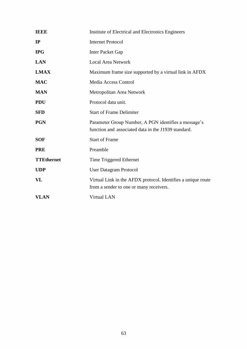
63
IEEE Institute of Electrical and Electronics Engineers
IP Internet Protocol
IPG Inter Packet Gap
LAN Local Area Network
LMAX Maximum frame size supported by a virtual link in AFDX
MAC Media Access Control
MAN Metropolitan Area Network
PDU Protocol data unit.
SFD Start of Frame Delimiter
PGN Parameter Group Number, A PGN identifies a message’s
function and associated data in the J1939 standard.
SOF Start of Frame
PRE Preamble
TTEthernet Time Triggered Ethernet
UDP User Datagram Protocol
VL Virtual Link in the AFDX protocol. Identifies a unique route
from a sender to one or many receivers.
VLAN Virtual LAN
TRITA-CSC-E 2011:126 ISRN-KTH/CSC/E--11/126-SE
ISSN-1653-5715
www.kth.se