ethernet lans
DESCRIPTION
Ethernet LANs. Chapter 4. Figure 4-1: A Short History of Ethernet Standards. Ethernet The dominant wired LAN technology today Only “competitor” is wireless LANs (which actually are supplementary) The IEEE 802 Committee - PowerPoint PPT PresentationTRANSCRIPT
Ethernet LANs
Chapter 4
4-2
Figure 4-1: A Short History of Ethernet Standards
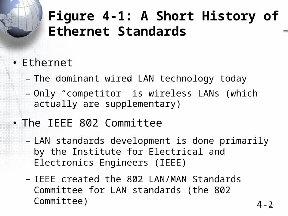
• Ethernet
– The dominant wired LAN technology today
– Only “competitor” is wireless LANs (which actually are supplementary)
• The IEEE 802 Committee
– LAN standards development is done primarily by the Institute for Electrical and Electronics Engineers (IEEE)
– IEEE created the 802 LAN/MAN Standards Committee for LAN standards (the 802 Committee)
4-3
Figure 4-1: A Short History of Ethernet Standards
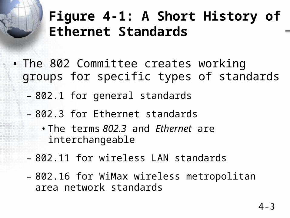
• The 802 Committee creates working groups for specific types of standards
– 802.1 for general standards
– 802.3 for Ethernet standards
• The terms 802.3 and Ethernet are interchangeable
– 802.11 for wireless LAN standards
– 802.16 for WiMax wireless metropolitan area network standards
4-4
Figure 4-1: A Short History of Ethernet Standards
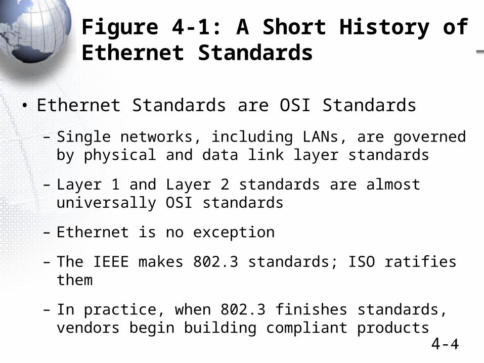
• Ethernet Standards are OSI Standards
– Single networks, including LANs, are governed by physical and data link layer standards
– Layer 1 and Layer 2 standards are almost universally OSI standards
– Ethernet is no exception
– The IEEE makes 802.3 standards; ISO ratifies them
– In practice, when 802.3 finishes standards, vendors begin building compliant products
Ethernet Physical Layer Standards
4-6
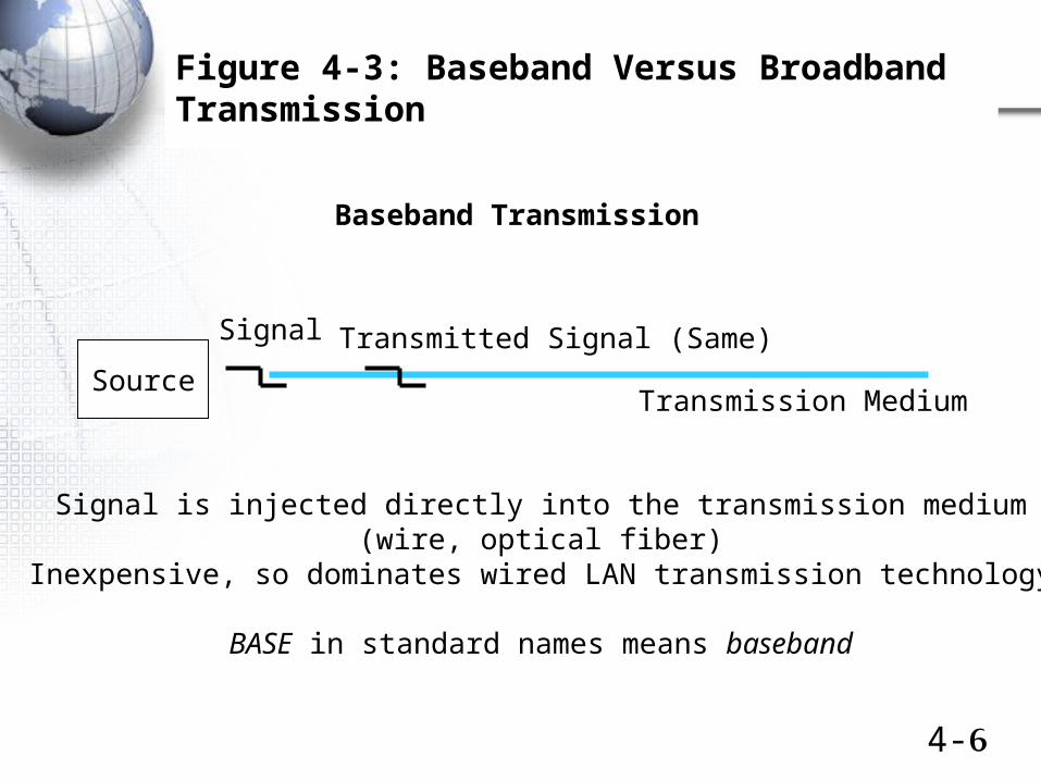
Figure 4-3: Baseband Versus Broadband Transmission
Baseband Transmission
Source
Signal Transmitted Signal (Same)
Transmission Medium
Signal is injected directly into the transmission medium(wire, optical fiber)
Inexpensive, so dominates wired LAN transmission technology
BASE in standard names means baseband
4-7
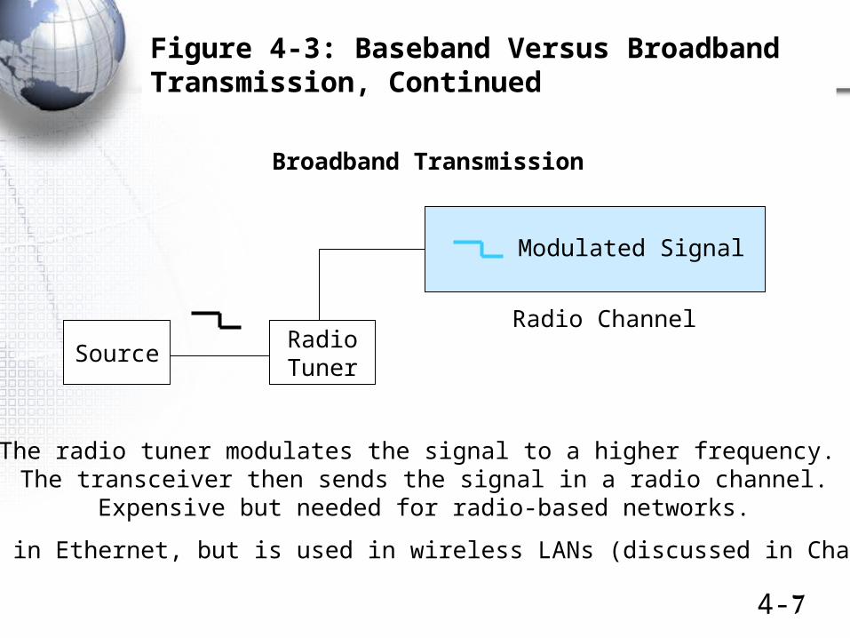
Figure 4-3: Baseband Versus Broadband Transmission, Continued
Broadband Transmission
SourceRadioTuner
Modulated Signal
Radio Channel
The radio tuner modulates the signal to a higher frequency. The transceiver then sends the signal in a radio channel.
Expensive but needed for radio-based networks.
Not used in Ethernet, but is used in wireless LANs (discussed in Chapter 5).
4-8
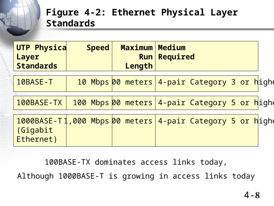
Figure 4-2: Ethernet Physical Layer Standards
UTP PhysicalLayerStandards
MediumRequired
MaximumRun
Length
Speed
100BASE-TX 4-pair Category 5 or higher100 meters100 Mbps
1000BASE-T(GigabitEthernet)
4-pair Category 5 or higher100 meters1,000 Mbps
10BASE-T 4-pair Category 3 or higher100 meters10 Mbps
100BASE-TX dominates access links today,
Although 1000BASE-T is growing in access links today
4-9
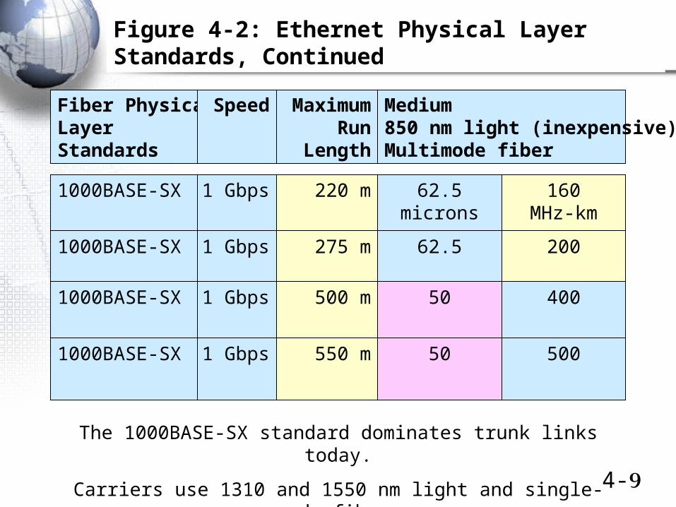
Fiber PhysicalLayerStandards
Medium850 nm light (inexpensive)Multimode fiber
MaximumRun
Length
Speed
1000BASE-SX 275 m1 Gbps
1000BASE-SX 500 m1 Gbps
1000BASE-SX 220 m1 Gbps
1000BASE-SX 550 m1 Gbps
Figure 4-2: Ethernet Physical Layer Standards, Continued
62.5microns
160MHz-km
62.5 200
50 400
50 500
The 1000BASE-SX standard dominates trunk links today.
Carriers use 1310 and 1550 nm light and single-mode fiber.
4-10
10 Gbps Ethernet
• 10 Gbps Ethernet usage is small but growing
• Several 10 Gbps fiber standards are defined, but none is dominant
Revised
4-11
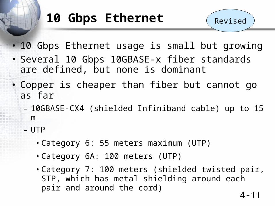
10 Gbps Ethernet
• 10 Gbps Ethernet usage is small but growing
• Several 10 Gbps 10GBASE-x fiber standards are defined, but none is dominant
• Copper is cheaper than fiber but cannot go as far– 10GBASE-CX4 (shielded Infiniband cable) up to 15 m
– UTP
• Category 6: 55 meters maximum (UTP)
• Category 6A: 100 meters (UTP)
• Category 7: 100 meters (shielded twisted pair, STP, which has metal shielding around each pair and around the cord)
Revised
4-12
100 Gbps Ethernet
• 100 Gbps has been selected as the next Ethernet speed
– Chosen over 40 Gbps
• 100 Gbps Ethernet standards development is just getting underway
NewInformation
4-13
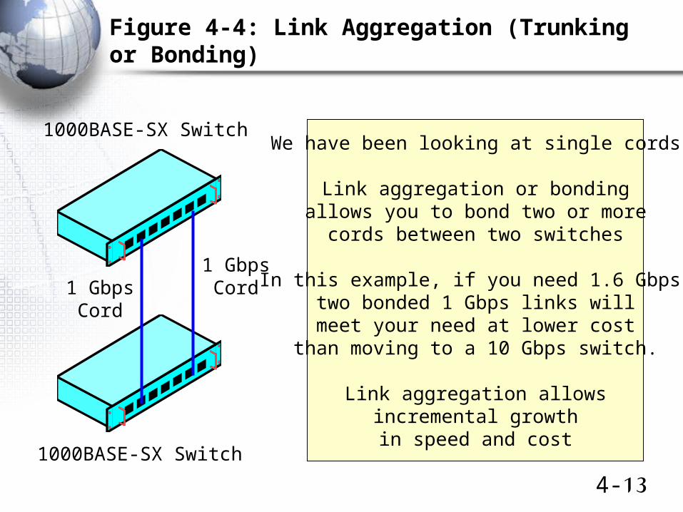
Figure 4-4: Link Aggregation (Trunking or Bonding)
1 GbpsCord1 Gbps
Cord
1000BASE-SX SwitchWe have been looking at single cords
Link aggregation or bondingallows you to bond two or more
cords between two switches
In this example, if you need 1.6 Gbps,two bonded 1 Gbps links willmeet your need at lower cost
than moving to a 10 Gbps switch.
Link aggregation allowsincremental growthin speed and cost
1000BASE-SX Switch
4-14
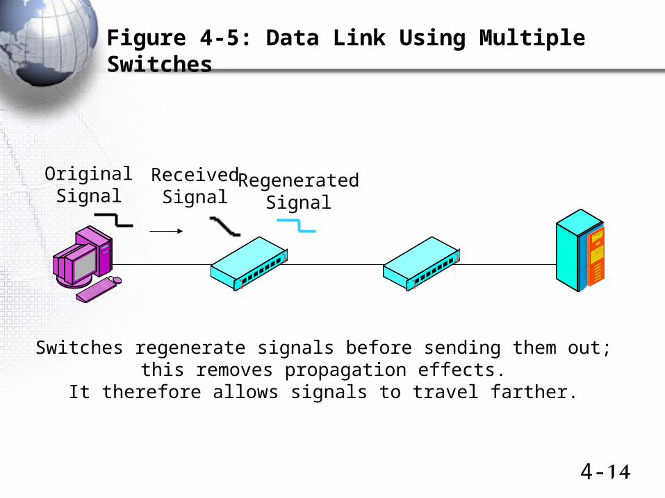
Figure 4-5: Data Link Using Multiple Switches
OriginalSignal
ReceivedSignal
RegeneratedSignal
Switches regenerate signals before sending them out;this removes propagation effects.
It therefore allows signals to travel farther.
4-15
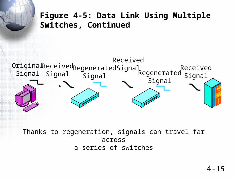
Figure 4-5: Data Link Using Multiple Switches, Continued
OriginalSignal
ReceivedSignal
ReceivedSignal
ReceivedSignalRegenerated
Signal RegeneratedSignal
Thanks to regeneration, signals can travel far acrossa series of switches

4-16
Figure 4-5: Data Link Using Multiple Switches, Continued
OriginalSignal
ReceivedSignal
ReceivedSignal
ReceivedSignalRegenerated
SignalRegenerated
Signal
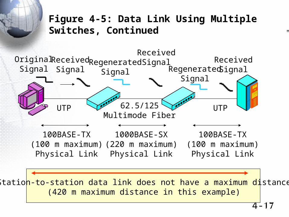
UTP UTP62.5/125Multimode Fiber
100BASE-TX(100 m maximum)
Physical Link
100BASE-TX(100 m maximum)
Physical Link
1000BASE-SX(220 m maximum)
Physical Link
Each trunk line along the way has a distance limit
4-17
Figure 4-5: Data Link Using Multiple Switches, Continued
Station-to-station data link does not have a maximum distance(420 m maximum distance in this example)
OriginalSignal
ReceivedSignal
ReceivedSignal
ReceivedSignalRegenerated
Signal RegeneratedSignal
UTP UTP62.5/125Multimode Fiber
100BASE-TX(100 m maximum)
Physical Link
100BASE-TX(100 m maximum)
Physical Link
1000BASE-SX(220 m maximum)
Physical Link
Ethernet Data Link (MAC) Layer Standards
802 Layering
Frame Syntax
Switch Operation
4-19
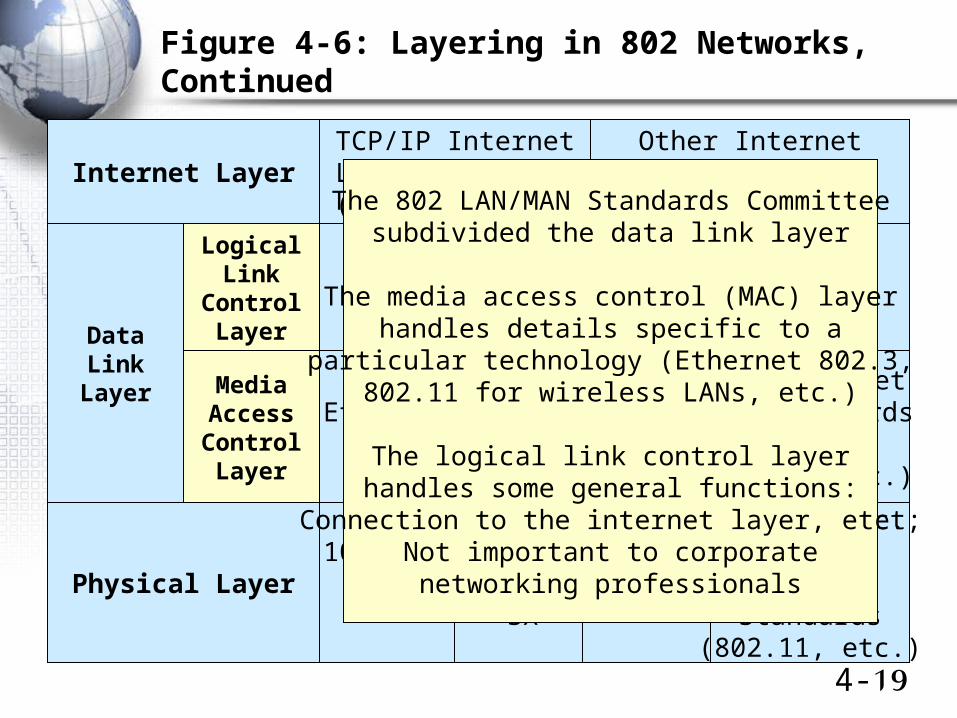
Figure 4-6: Layering in 802 Networks, Continued
TCP/IP InternetLayer Standards(IP, ARP, etc.)
Other InternetLayer Standards
(IPX, etc.)
802.2
Ethernet 802.3 MAC LayerStandard
Physical Layer
MediaAccessControlLayer
Non-EthernetMAC Standards
(802.5,802.11, etc.)
100BASE-TX
1000Base-
SX…
LogicalLink
ControlLayer
Non-EthernetPhysical
LayerStandards
(802.11, etc.)
DataLink
Layer
Internet LayerThe 802 LAN/MAN Standards Committee
subdivided the data link layer
The media access control (MAC) layerhandles details specific to a
particular technology (Ethernet 802.3,802.11 for wireless LANs, etc.)
The logical link control layerhandles some general functions:
Connection to the internet layer, etc.;Not important to corporatenetworking professionals
4-20
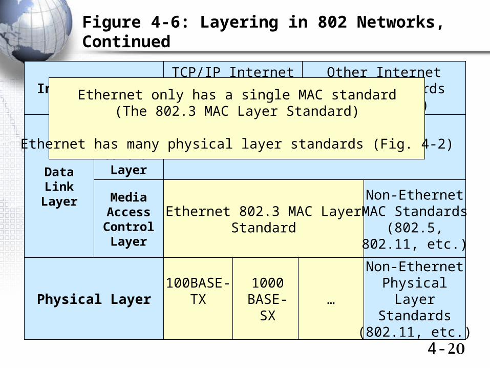
Figure 4-6: Layering in 802 Networks, Continued
TCP/IP InternetLayer Standards(IP, ARP, etc.)
Other InternetLayer Standards
(IPX, etc.)
802.2
Ethernet 802.3 MAC LayerStandard
Physical Layer
MediaAccessControlLayer
Non-EthernetMAC Standards
(802.5,802.11, etc.)
100BASE-TX
1000BASE-
SX…
LogicalLink
ControlLayer
Non-EthernetPhysical
LayerStandards
(802.11, etc.)
DataLink
Layer
Internet LayerEthernet only has a single MAC standard(The 802.3 MAC Layer Standard)
Ethernet has many physical layer standards (Fig. 4-2)
4-21
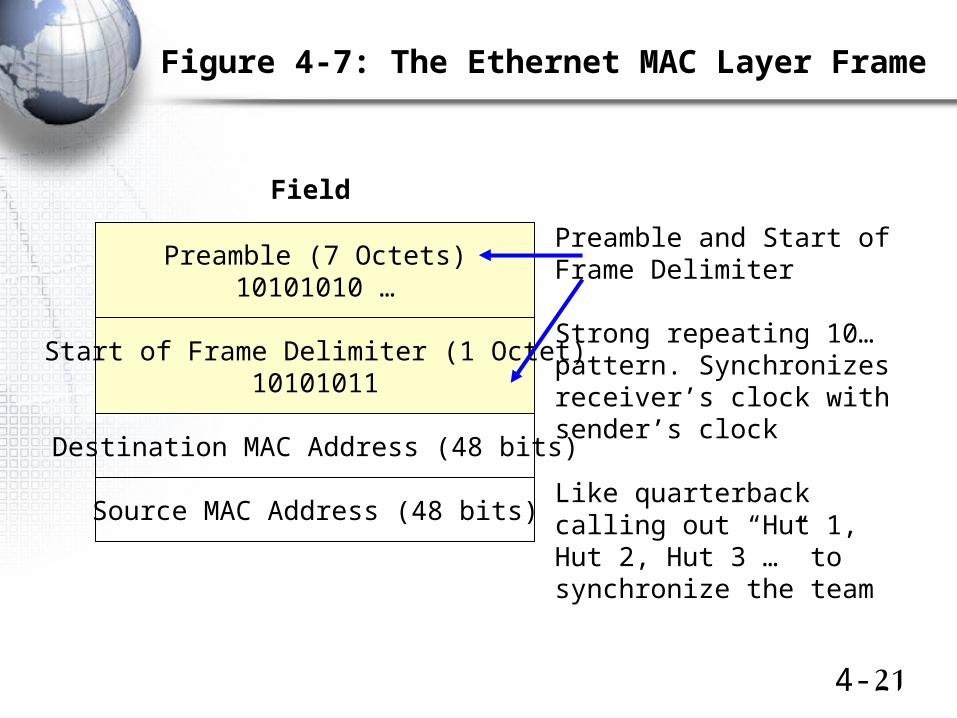
Figure 4-7: The Ethernet MAC Layer Frame
Preamble (7 Octets)10101010 …
Start of Frame Delimiter (1 Octet)10101011
Destination MAC Address (48 bits)
Source MAC Address (48 bits)
Field
Preamble and Start ofFrame Delimiter
Strong repeating 10…pattern. Synchronizesreceiver’s clock withsender’s clock
Like quarterbackcalling out “Hut 1,Hut 2, Hut 3 …” tosynchronize the team
4-22
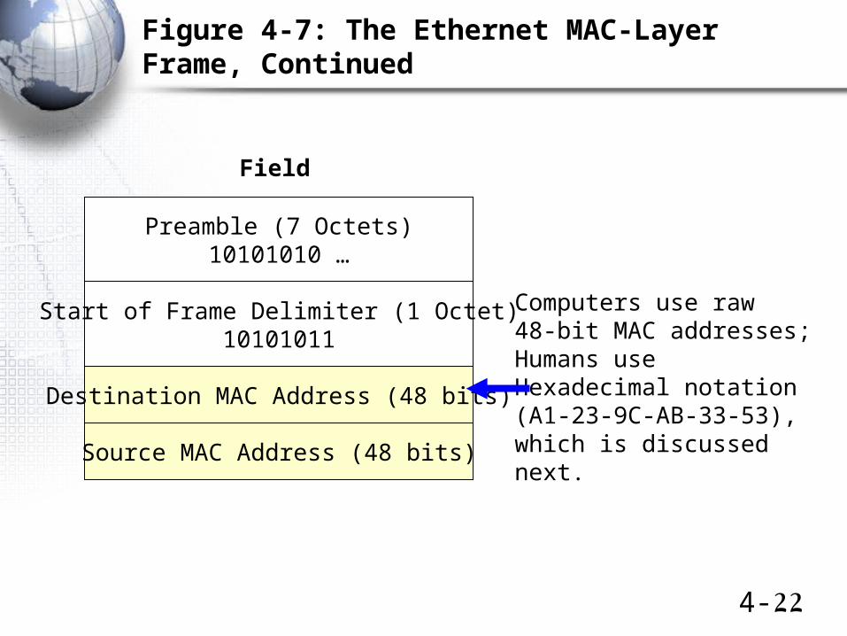
Figure 4-7: The Ethernet MAC-Layer Frame, Continued
Preamble (7 Octets)10101010 …
Start of Frame Delimiter (1 Octet)10101011
Destination MAC Address (48 bits)
Source MAC Address (48 bits)
Field
Computers use raw48-bit MAC addresses;Humans useHexadecimal notation(A1-23-9C-AB-33-53),which is discussednext.
4-23
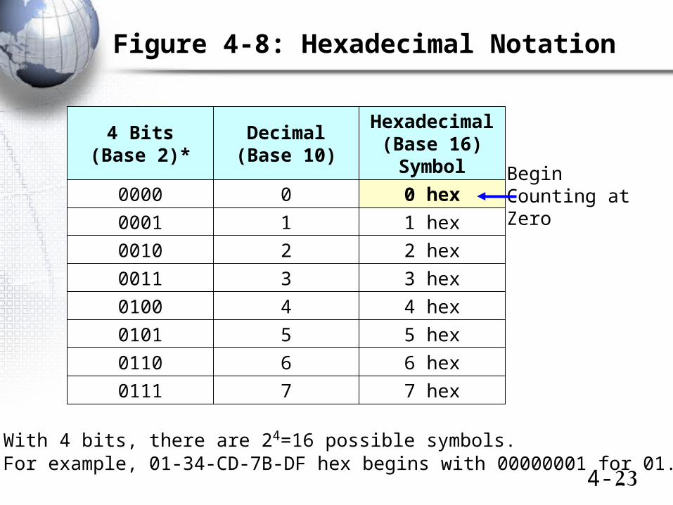
Figure 4-8: Hexadecimal Notation
4 Bits(Base 2)*
Decimal(Base 10)
Hexadecimal(Base 16)Symbol
0000 0 0 hex
0001 1 1 hex
0010 2 2 hex
•With 4 bits, there are 24=16 possible symbols.•For example, 01-34-CD-7B-DF hex begins with 00000001 for 01.
0011 3 3 hex
0100 4 4 hex
0101 5 5 hex
0110 6 6 hex
0111 7 7 hex
BeginCounting atZero
4-24
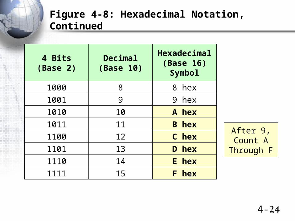
Figure 4-8: Hexadecimal Notation, Continued
4 Bits(Base 2)
Decimal(Base 10)
Hexadecimal(Base 16)Symbol
1000 8 8 hex
1001 9 9 hex
1010 10 A hex
1011 11 B hex
1100 12 C hex
1101 13 D hex
1110 14 E hex
1111 15 F hex
After 9,Count A
Through F
4-25
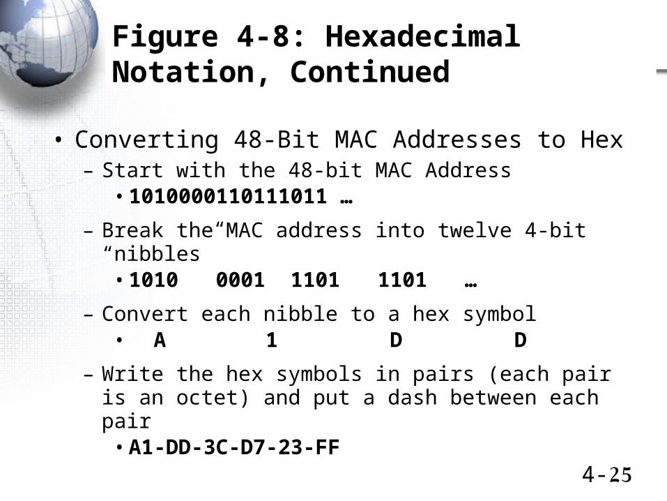
Figure 4-8: Hexadecimal Notation, Continued
• Converting 48-Bit MAC Addresses to Hex– Start with the 48-bit MAC Address
• 1010000110111011 …
– Break the MAC address into twelve 4-bit “nibbles”• 1010 0001 1101 1101 …
– Convert each nibble to a hex symbol• A 1 D D
– Write the hex symbols in pairs (each pair is an octet) and put a dash between each pair
• A1-DD-3C-D7-23-FF
4-26
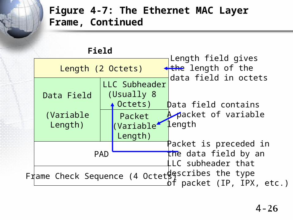
Figure 4-7: The Ethernet MAC Layer Frame, Continued
Length (2 Octets)
PAD
Field
Packet(VariableLength)
LLC Subheader(Usually 8
Octets)Data Field
(VariableLength)
Frame Check Sequence (4 Octets)
Data field containsA packet of variablelength
Packet is preceded inthe data field by anLLC subheader thatdescribes the typeof packet (IP, IPX, etc.)
Length field givesthe length of thedata field in octets
4-27
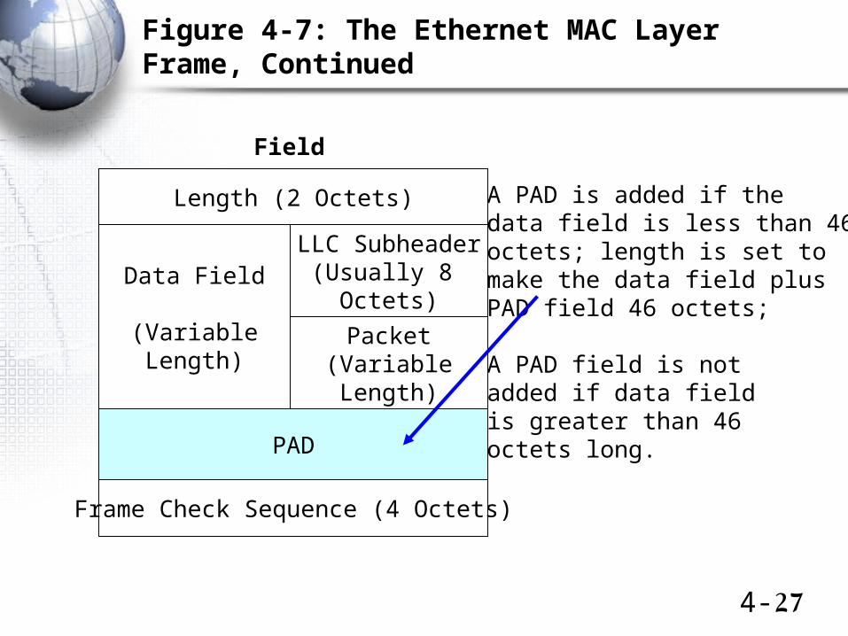
Figure 4-7: The Ethernet MAC Layer Frame, Continued
Length (2 Octets)
PAD
Field
Packet(VariableLength)
LLC Subheader(Usually 8
Octets)Data Field
(VariableLength)
Frame Check Sequence (4 Octets)
A PAD is added if the data field is less than 46octets; length is set tomake the data field plusPAD field 46 octets;
A PAD field is notadded if data fieldis greater than 46octets long.
4-28
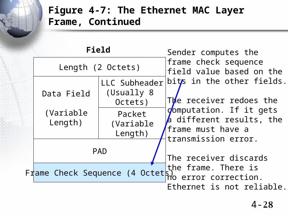
Figure 4-7: The Ethernet MAC Layer Frame, Continued
Length (2 Octets)
PAD
Field
Packet(VariableLength)
LLC Subheader(Usually 8
Octets)Data Field
(VariableLength)
Frame Check Sequence (4 Octets)
Sender computes theframe check sequencefield value based on thebits in the other fields.
The receiver redoes thecomputation. If it getsa different results, theframe must have atransmission error.
The receiver discardsthe frame. There isno error correction.Ethernet is not reliable.
4-29
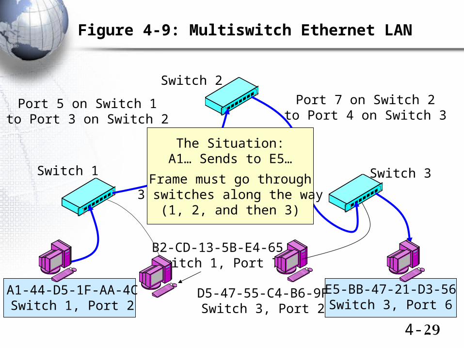
Figure 4-9: Multiswitch Ethernet LAN
Switch 2
Switch 1 Switch 3
Port 5 on Switch 1to Port 3 on Switch 2
Port 7 on Switch 2to Port 4 on Switch 3
A1-44-D5-1F-AA-4CSwitch 1, Port 2
E5-BB-47-21-D3-56Switch 3, Port 6
D5-47-55-C4-B6-9FSwitch 3, Port 2
B2-CD-13-5B-E4-65Switch 1, Port 7
The Situation:A1… Sends to E5…
Frame must go through3 switches along the way
(1, 2, and then 3)
4-30
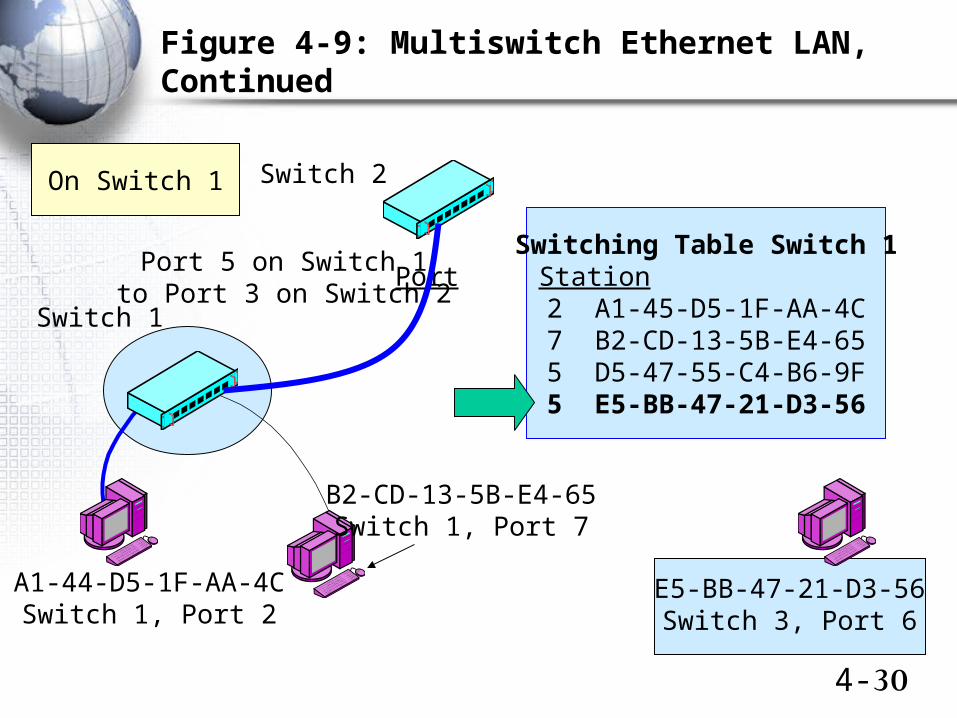
Figure 4-9: Multiswitch Ethernet LAN, Continued
Switching Table Switch 1Port Station
2 A1-45-D5-1F-AA-4C7 B2-CD-13-5B-E4-655 D5-47-55-C4-B6-9F5 E5-BB-47-21-D3-56
Switch 2
Switch 1
Port 5 on Switch 1to Port 3 on Switch 2
A1-44-D5-1F-AA-4CSwitch 1, Port 2
B2-CD-13-5B-E4-65Switch 1, Port 7
E5-BB-47-21-D3-56Switch 3, Port 6
On Switch 1
4-31
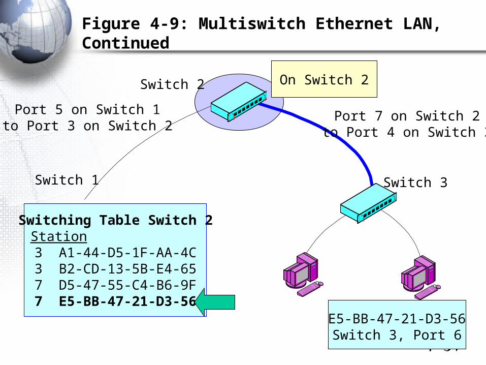
Figure 4-9: Multiswitch Ethernet LAN, Continued
Switch 2
Switch 1 Switch 3
Port 5 on Switch 1to Port 3 on Switch 2
Port 7 on Switch 2to Port 4 on Switch 3
Switching Table Switch 2Port Station
3 A1-44-D5-1F-AA-4C3 B2-CD-13-5B-E4-657 D5-47-55-C4-B6-9F7 E5-BB-47-21-D3-56
E5-BB-47-21-D3-56Switch 3, Port 6
On Switch 2
4-32
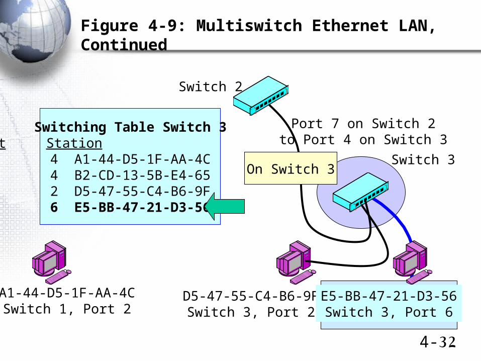
Figure 4-9: Multiswitch Ethernet LAN, Continued
Switch 2
Switch 3
Port 7 on Switch 2to Port 4 on Switch 3
A1-44-D5-1F-AA-4CSwitch 1, Port 2
D5-47-55-C4-B6-9FSwitch 3, Port 2
Switching Table Switch 3Port Station
4 A1-44-D5-1F-AA-4C4 B2-CD-13-5B-E4-652 D5-47-55-C4-B6-9F6 E5-BB-47-21-D3-56
E5-BB-47-21-D3-56Switch 3, Port 6
On Switch 3
4-33
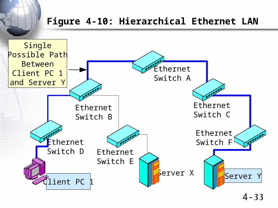
Figure 4-10: Hierarchical Ethernet LAN
Client PC 1
EthernetSwitch F
Server YServer X
SinglePossible Path
BetweenClient PC 1
and Server Y
EthernetSwitch E
EthernetSwitch D
EthernetSwitch B
EthernetSwitch A
EthernetSwitch C
4-34
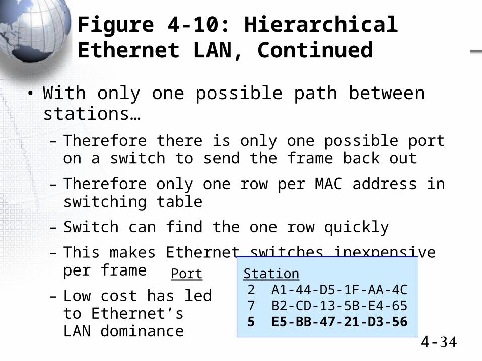
Figure 4-10: Hierarchical Ethernet LAN, Continued
• With only one possible path between stations…
– Therefore there is only one possible port on a switch to send the frame back out
– Therefore only one row per MAC address in switching table
– Switch can find the one row quickly
– This makes Ethernet switches inexpensive per frame
– Low cost has ledto Ethernet’sLAN dominance
Port Station 2 A1-44-D5-1F-AA-4C7 B2-CD-13-5B-E4-655 E5-BB-47-21-D3-56
4-35
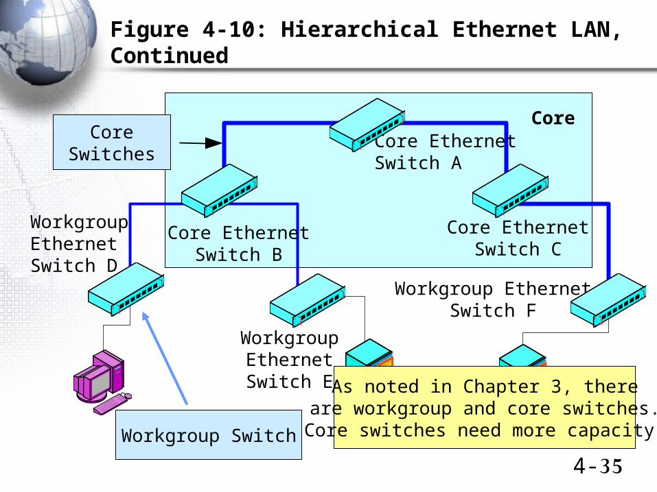
Figure 4-10: Hierarchical Ethernet LAN, Continued
Workgroup EthernetSwitch F
CoreSwitches
WorkgroupEthernetSwitch E
WorkgroupEthernetSwitch D
Core EthernetSwitch B
Core EthernetSwitch A
Core EthernetSwitch C
Core
Workgroup Switch
As noted in Chapter 3, thereare workgroup and core switches.
Core switches need more capacity.
4-36
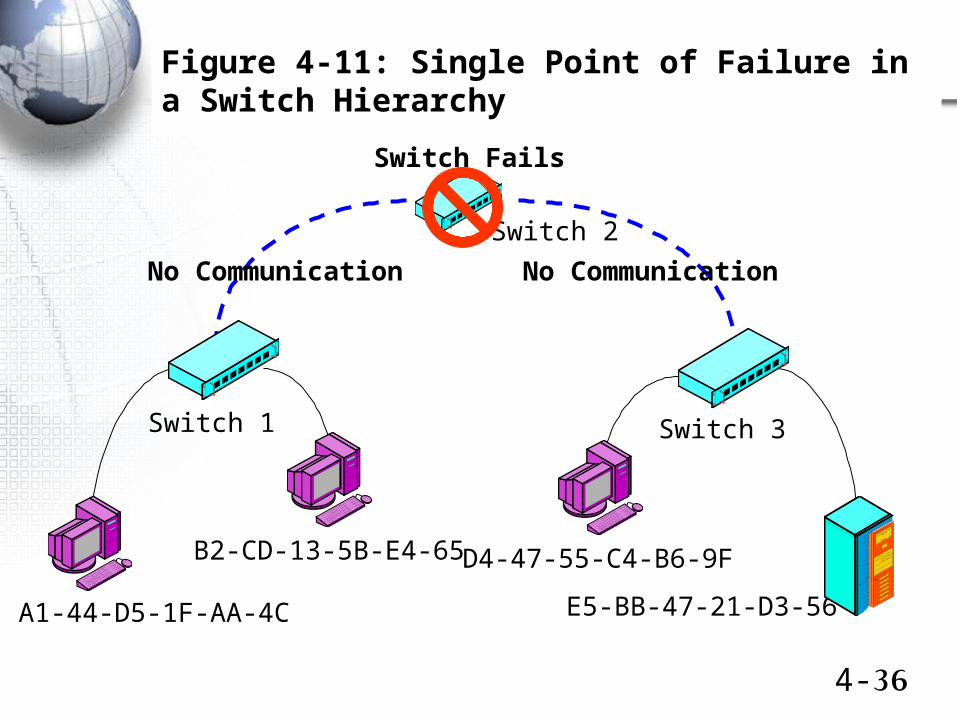
Figure 4-11: Single Point of Failure in a Switch Hierarchy
No CommunicationNo Communication
Switch 1
Switch 2
Switch 3
Switch Fails
A1-44-D5-1F-AA-4C
B2-CD-13-5B-E4-65 D4-47-55-C4-B6-9F
E5-BB-47-21-D3-56
4-37
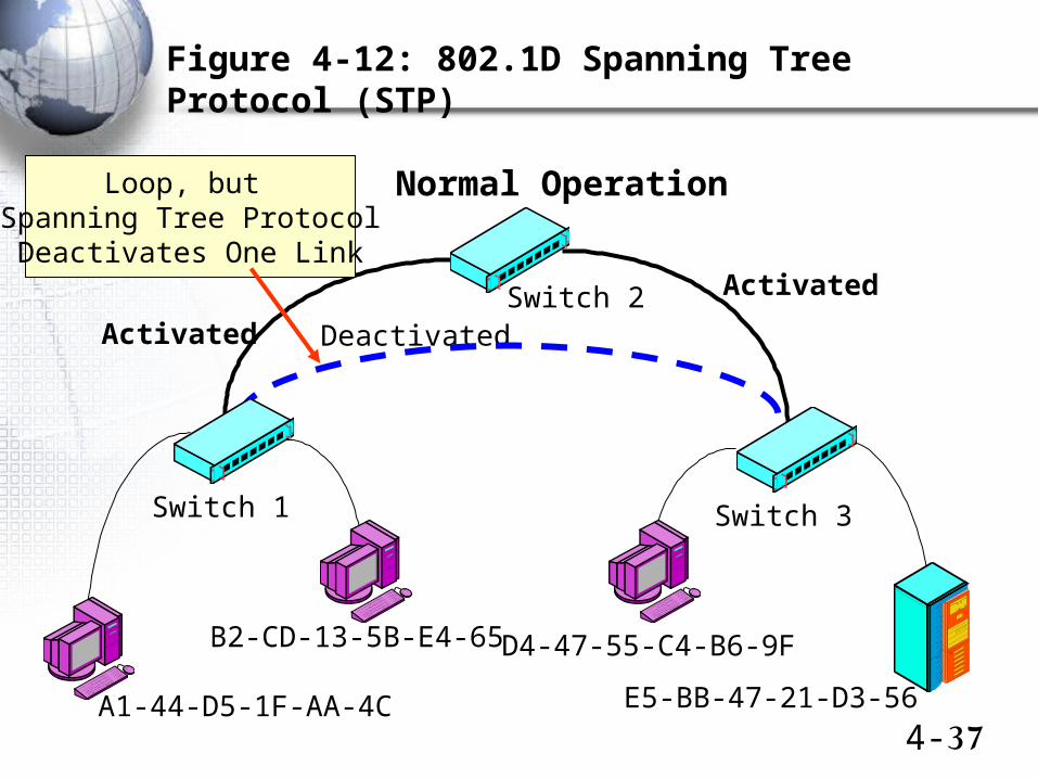
Figure 4-12: 802.1D Spanning Tree Protocol (STP)
Switch 1
Switch 2
Switch 3
A1-44-D5-1F-AA-4C
B2-CD-13-5B-E4-65 D4-47-55-C4-B6-9F
E5-BB-47-21-D3-56
Activated
Activated
Deactivated
Normal OperationLoop, but Spanning Tree ProtocolDeactivates One Link
4-38
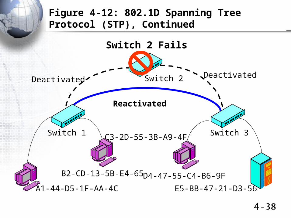
Figure 4-12: 802.1D Spanning Tree Protocol (STP), Continued
Switch 1
Switch 2
Switch 3
A1-44-D5-1F-AA-4C
B2-CD-13-5B-E4-65
C3-2D-55-3B-A9-4F
D4-47-55-C4-B6-9F
E5-BB-47-21-D3-56
Deactivated Deactivated
Reactivated
Switch 2 Fails
4-39
Figure 4-12: 802.1D (STP), Continued
• Spanning Tree Protocol (STP)
– Works but when there is a break in the hierarchy, the network converges to a new hierarchy too slowly
• Rapid Spanning Tree Protocol (RSTP)
– Newer algorithm that converges very quickly
Virtual LANs (VLANs)
4-41
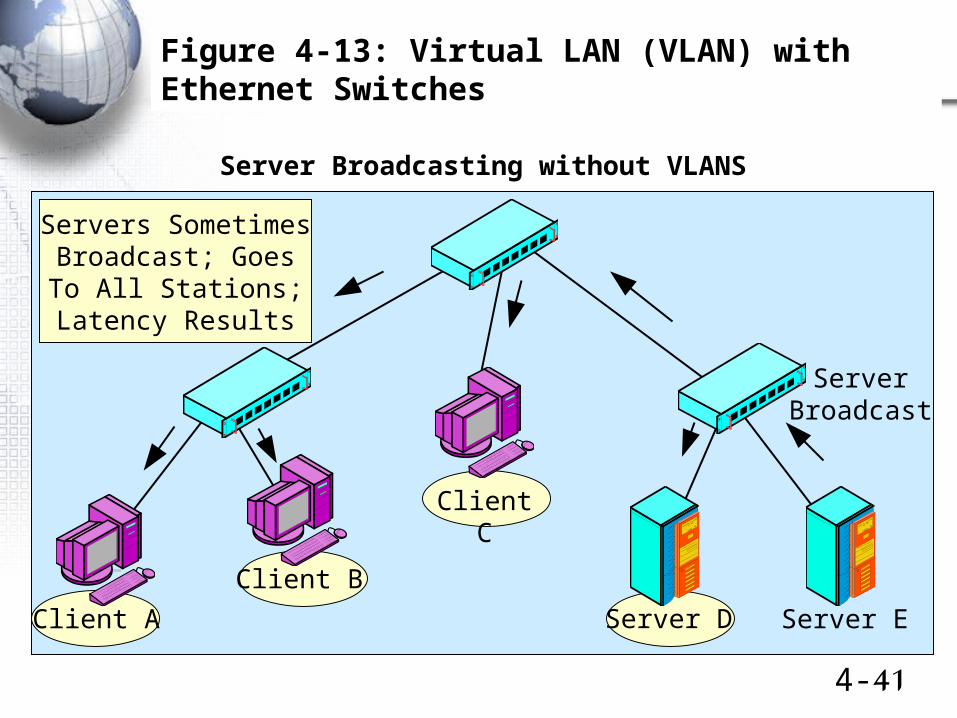
Figure 4-13: Virtual LAN (VLAN) with Ethernet Switches
Client A
Client B
Client C
Server D Server E
ServerBroadcast
Server Broadcasting without VLANS
Servers SometimesBroadcast; GoesTo All Stations;Latency Results
4-42
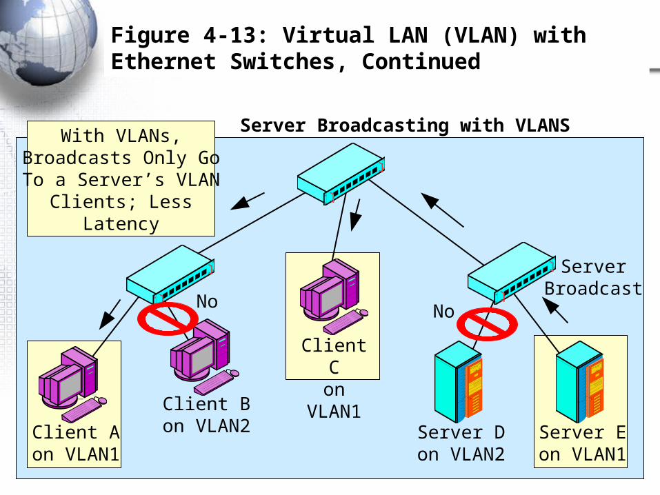
Figure 4-13: Virtual LAN (VLAN) with Ethernet Switches, Continued
Server Broadcasting with VLANS
Client Aon VLAN1
Client Bon VLAN2
Client Con VLAN1
Server Don VLAN2
Server Eon VLAN1
ServerBroadcast
NoNo
With VLANs,Broadcasts Only GoTo a Server’s VLAN
Clients; LessLatency
4-43
Figure 4-13: Virtual LAN (VLAN) with Ethernet Switches, Continued
• VLANs primarily reduce congestion due to latency– They can also be used for security
• Only people on a server’s VLAN can reach it– This provides some degree of security
– Not sufficient by itself, but it can help
• Wireless LANs– In wireless LANs, wireless clients may be initially placed
in a VLAN that only has a single server—a server that authenticates the clients
– After authentication, clients are allowed beyond the initial VLAN
4-44
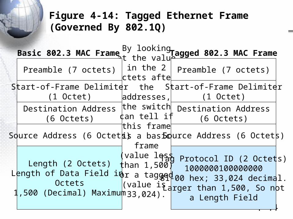
Figure 4-14: Tagged Ethernet Frame (Governed By 802.1Q)
Destination Address(6 Octets)
Destination Address(6 Octets)
Source Address (6 Octets)
Length (2 Octets)Length of Data Field in
Octets1,500 (Decimal) Maximum
Tag Protocol ID (2 Octets)1000000100000000
81-00 hex; 33,024 decimal.Larger than 1,500, So not
a Length Field
By lookingat the value
in the 2octets after
theaddresses,the switchcan tell ifthis frameis a basic
frame(value lessthan 1,500)or a tagged(value is 33,024).
Basic 802.3 MAC Frame Tagged 802.3 MAC Frame
Start-of-Frame Delimiter(1 Octet)
Preamble (7 octets)
Start-of-Frame Delimiter(1 Octet)
Preamble (7 octets)
Source Address (6 Octets)
4-45
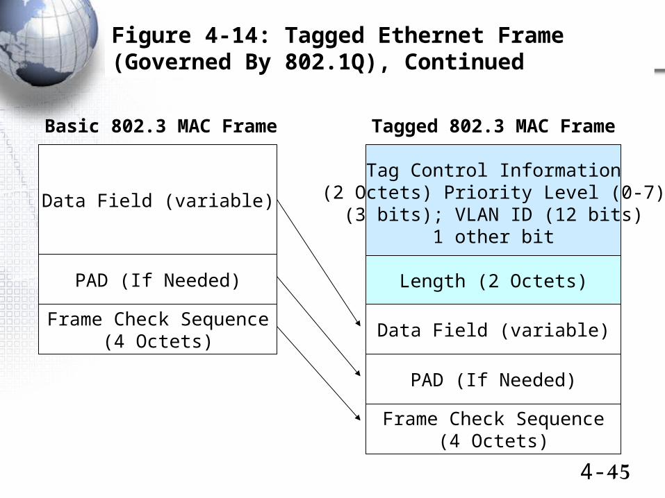
Figure 4-14: Tagged Ethernet Frame (Governed By 802.1Q), Continued
Tag Control Information(2 Octets) Priority Level (0-7)
(3 bits); VLAN ID (12 bits)1 other bit
Basic 802.3 MAC Frame Tagged 802.3 MAC Frame
Length (2 Octets)
Data Field (variable)
Data Field (variable)
PAD (If Needed)
Frame Check Sequence(4 Octets)
PAD (If Needed)
Frame Check Sequence(4 Octets)
4-46
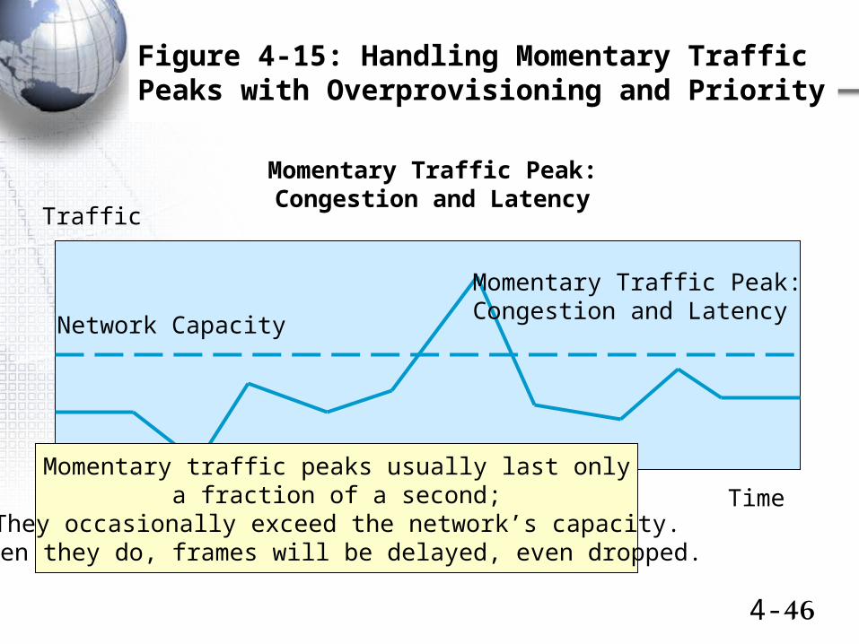
Figure 4-15: Handling Momentary Traffic Peaks with Overprovisioning and Priority
Traffic
Network Capacity
Momentary Traffic Peak:Congestion and Latency
Time
Momentary Traffic Peak:Congestion and Latency
Momentary traffic peaks usually last onlya fraction of a second;
They occasionally exceed the network’s capacity.When they do, frames will be delayed, even dropped.
4-47
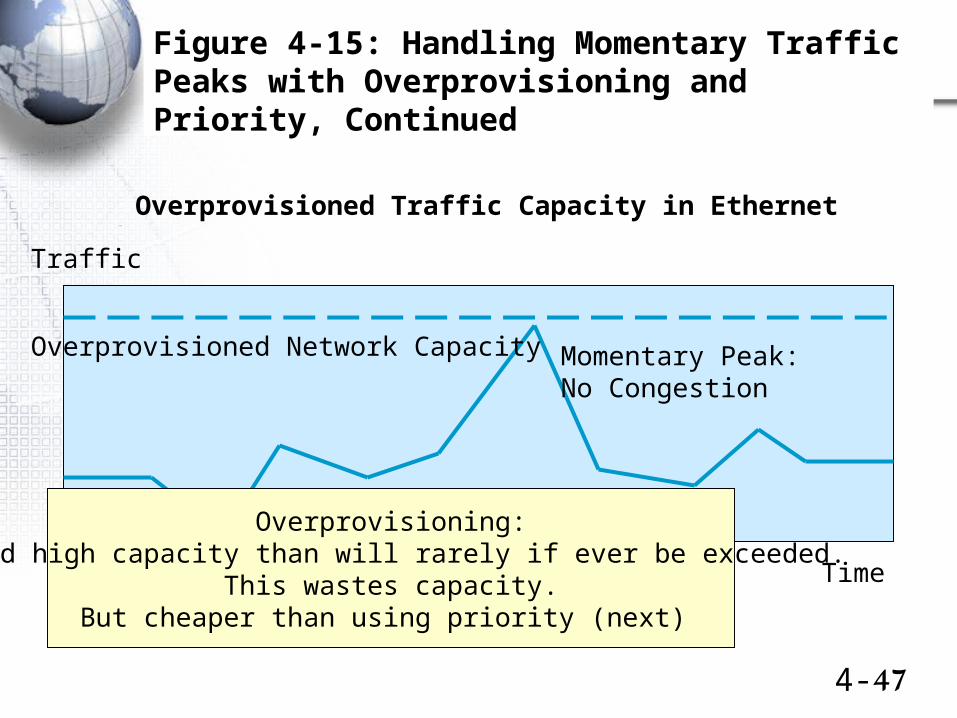
Figure 4-15: Handling Momentary Traffic Peaks with Overprovisioning and Priority, Continued
Traffic
Overprovisioned Network Capacity Momentary Peak:No Congestion
Time
Overprovisioned Traffic Capacity in Ethernet
Overprovisioning:Build high capacity than will rarely if ever be exceeded.
This wastes capacity.But cheaper than using priority (next)
4-48
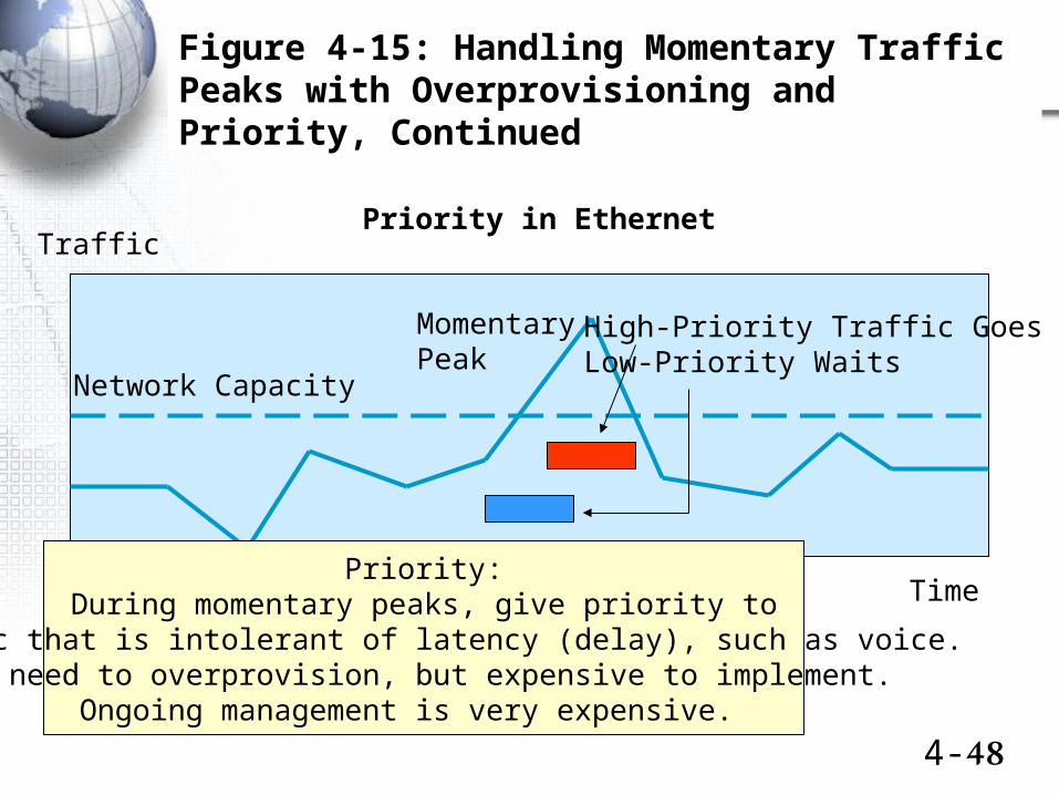
Figure 4-15: Handling Momentary Traffic Peaks with Overprovisioning and Priority, Continued
Traffic
Network Capacity
MomentaryPeak
Time
Priority in Ethernet
High-Priority Traffic GoesLow-Priority Waits
Priority:During momentary peaks, give priority to
traffic that is intolerant of latency (delay), such as voice.No need to overprovision, but expensive to implement.
Ongoing management is very expensive.