etsi en 300 417-1-1 v1.2 · etsi 7 etsi en 300 417-1-1 v1.2.1 (2001-10) intellectual property...
TRANSCRIPT

ETSI EN 300 417-1-1 V1.2.1 (2001-10)
European Standard (Telecommunications series)
Transmission and Multiplexing (TM);Generic requirements of transport functionality of equipment;
Part 1-1: Generic processes and performance
ETSI
ETSI EN 300 417-1-1 V1.2.1 (2001-10)2
Reference REN/TM-01042-1-1
Keywords architecture, generic, performance, SDH,
transmission, transport
ETSI
650 Route des Lucioles F-06921 Sophia Antipolis Cedex - FRANCE
Tel.: +33 4 92 94 42 00 Fax: +33 4 93 65 47 16
Siret N° 348 623 562 00017 - NAF 742 C
Association à but non lucratif enregistrée à la Sous-Préfecture de Grasse (06) N° 7803/88
Important notice
Individual copies of the present document can be downloaded from: http://www.etsi.org
The present document may be made available in more than one electronic version or in print. In any case of existing or perceived difference in contents between such versions, the reference version is the Portable Document Format (PDF).
In case of dispute, the reference shall be the printing on ETSI printers of the PDF version kept on a specific network drive within ETSI Secretariat.
Users of the present document should be aware that the document may be subject to revision or change of status. Information on the current status of this and other ETSI documents is available at
http://portal.etsi.org/tb/status/status.asp
If you find errors in the present document, send your comment to: [email protected]
Copyright Notification
No part may be reproduced except as authorized by written permission. The copyright and the foregoing restriction extend to reproduction in all media.
© European Telecommunications Standards Institute 2001.
All rights reserved.
ETSI
ETSI EN 300 417-1-1 V1.2.1 (2001-10)3
Contents
Intellectual Property Rights ................................................................................................................................7
Foreword.............................................................................................................................................................7
1 Scope ........................................................................................................................................................9
2 References ................................................................................................................................................9
3 Abbreviations, definitions and symbols .................................................................................................11 3.1 Abbreviations ...................................................................................................................................................11 3.2 Definitions........................................................................................................................................................14 3.3 Naming and numbering conventions................................................................................................................19 3.3.1 Bit numbering scheme ................................................................................................................................19 3.3.2 STM-N SOH byte numbering scheme ........................................................................................................19 3.3.3 Atomic function naming scheme ................................................................................................................20 3.3.4 Information naming scheme .......................................................................................................................20 3.3.5 AU/TU numbering scheme .........................................................................................................................21 3.3.5.1 AU numbering scheme..........................................................................................................................21 3.3.5.2 TU numbering scheme within a VC-4 ..................................................................................................24 3.3.5.3 TU numbering scheme within a P31s....................................................................................................28 3.3.5.4 TU numbering scheme within a P4s......................................................................................................28 3.3.6 Reference points numbering scheme ..........................................................................................................29 3.3.7 Tributary port numbering scheme...............................................................................................................29 3.3.8 PU numbering scheme ................................................................................................................................29 3.3.9 Supervision variables numbering scheme...................................................................................................30 3.4 Symbols and diagrammatic conventions ..........................................................................................................30
4 Introduction ............................................................................................................................................32 4.1 Functional modelling rationale.........................................................................................................................33 4.1.1 Description of network elements - equipment functional specification......................................................33 4.1.2 Implementation independence ....................................................................................................................33 4.1.3 Universal representation for management ..................................................................................................33 4.2 The underlying principles of functional modelling ..........................................................................................34 4.2.1 The client-server relationship .....................................................................................................................34 4.2.2 Atomic functions and compound functions ................................................................................................34 4.2.3 Network functions included in specific equipment.....................................................................................34 4.2.4 The functional model and the information model.......................................................................................34
5 Network layering principles ...................................................................................................................35 5.1 Transmission layers..........................................................................................................................................35 5.2 Atomic functions ..............................................................................................................................................36 5.2.1 Connection function....................................................................................................................................37 5.2.2 Trail termination function...........................................................................................................................37 5.2.3 Adaptation function ....................................................................................................................................38 5.3 Reference points ...............................................................................................................................................40 5.4 Transmission sub-layers ...................................................................................................................................40
6 Combination rules ..................................................................................................................................40 6.1 General .............................................................................................................................................................40 6.1.1 Binding at connection points ......................................................................................................................40 6.1.2 Binding at (termination) connection points ................................................................................................41 6.1.3 Binding at APs............................................................................................................................................41 6.1.4 Alternative binding representations ............................................................................................................42 6.2 Directionality....................................................................................................................................................42 6.3 Compound functions ........................................................................................................................................43 6.4 Major compound functions...............................................................................................................................43 6.5 Trail, (sub)network connections, link connections, matrix connections, and tandem connections ..................44 6.6 Matrix connections ...........................................................................................................................................44 6.6.1 1-port ..........................................................................................................................................................45 6.6.2 2-port ..........................................................................................................................................................45

ETSI
ETSI EN 300 417-1-1 V1.2.1 (2001-10)4
6.6.3 3-port ..........................................................................................................................................................46 6.6.4 4-port ..........................................................................................................................................................46
7 Maintenance signals and processes ........................................................................................................47 7.1 Trail Trace Identifier (TTI) ..............................................................................................................................47 7.2 Trail Signal Label (TSL) ..................................................................................................................................49 7.2.1 Unequipped signal application....................................................................................................................49 7.2.2 Supervisory-unequipped signal application ................................................................................................50 7.2.3 Adaptation function selection supervision process .....................................................................................52 7.2.4 Connection monitoring application.............................................................................................................52 7.3 Error Detection Code (EDC) ............................................................................................................................53 7.4 Remote indications ...........................................................................................................................................53 7.4.1 Remote Defect Indication (RDI).................................................................................................................53 7.4.2 Remote Error Indication (REI) ...................................................................................................................54 7.5 Alarm Indication Signal (AIS) .........................................................................................................................55 7.6 Non-intrusive monitoring of characteristic information at connection points ..................................................57 7.6.1 Fault localization scenario using non-intrusive monitors ...........................................................................58 7.7 Signal fail and signal degrade...........................................................................................................................59 7.7.1 Server Signal Fail (CI_SSF) signal.............................................................................................................59 7.7.2 Server Signal Fail failure (fSSF).................................................................................................................59 7.7.3 Server Signal Degrade (aSSD) signal .........................................................................................................60 7.7.4 Trail Signal Fail (AI_TSF) signal ...............................................................................................................60 7.7.5 Trail Signal Degrade (aTSD) signal ...........................................................................................................60
8 Supervision process................................................................................................................................60 8.1 Introduction ......................................................................................................................................................60 8.2 Atomic function fault management ..................................................................................................................62 8.2.1 Defect filter f1.............................................................................................................................................64 8.2.1.1 Introduction...........................................................................................................................................64 8.2.1.2 Trail Signal Label (TSL).......................................................................................................................64 8.2.1.3 Trail Trace Identifier (TTI) ...................................................................................................................66 8.2.1.4 Error Detection Code (EDC) violation and Degraded (DEG)...............................................................67 8.2.1.5 Remote Defect Indicator (RDI).............................................................................................................68 8.2.1.6 Loss of signal ........................................................................................................................................68 8.2.1.7 Alarm Indication Signal (AIS) ..............................................................................................................69 8.2.1.7.1 PDH signals .....................................................................................................................................69 8.2.1.7.2 SDH signals .....................................................................................................................................69 8.2.1.8 Loss of frame, multiframe, pointer, tandem connection, sequence structure ........................................70 8.2.1.9 Failure of protocol.................................................................................................................................71 8.2.1.10 Equipment defects.................................................................................................................................71 8.2.1.11 Transmit Fail .........................................................................................................................................71 8.2.1.12 Loss of Tandem Connection Unequipped (dUNEQ) ............................................................................71 8.2.2 Consequent action filter f2..........................................................................................................................72 8.2.2.1 Alarm Indication Signal (AIS) ..............................................................................................................73 8.2.2.2 Remote Defect Indicator (RDI).............................................................................................................74 8.2.2.3 Remote Error Indication (REI)..............................................................................................................74 8.2.2.4 Server Signal Fail (SSF)........................................................................................................................75 8.2.2.5 Trail Signal Fail (TSF) ..........................................................................................................................75 8.2.2.6 Trail Signal Degrade (TSD) ..................................................................................................................75 8.2.2.7 Unequipped Virtual Container (VC) signal...........................................................................................76 8.2.2.8 Unit Failure (UF) ..................................................................................................................................76 8.2.2.9 (Automatic) laser shutdown (ALS/LS) .................................................................................................76 8.2.2.10 Server Signal Degrade (SSD)................................................................................................................76 8.2.3 Fault cause filter f3 .....................................................................................................................................76 8.2.3.1 Termination sink function .....................................................................................................................76 8.2.3.2 Termination supervisory sink function..................................................................................................77 8.2.3.3 Adaptation sink function .......................................................................................................................77 8.2.3.4 Connection function ..............................................................................................................................78 8.2.4 Performance monitoring filter f11 (pN_EBC) ............................................................................................78 8.2.5 Performance monitoring filter f12 (pN_DS)...............................................................................................78 8.2.6 Performance monitoring filter f21 (pF_EBC).............................................................................................78 8.2.7 Performance monitoring filter f22 (pF_DS) ...............................................................................................78

ETSI
ETSI EN 300 417-1-1 V1.2.1 (2001-10)5
8.2.8 pPJE............................................................................................................................................................78 8.3 Equipment management function fault management process ..........................................................................79 8.4 Equipment Management Function (EMF) performance monitoring process ...................................................79 8.5 Trail termination point mode and port mode....................................................................................................79 8.6 Access point mode............................................................................................................................................80
9 Protection process ..................................................................................................................................80 9.1 Introduction ......................................................................................................................................................80 9.2 General .............................................................................................................................................................80 9.2.1 Protection architectures...............................................................................................................................81 9.2.2 Switching types...........................................................................................................................................83 9.2.2.1 APS channel provisioning.....................................................................................................................83 9.2.2.2 APS channel usage................................................................................................................................84 9.2.2.3 APS channel coding ..............................................................................................................................84 9.2.3 Operation types ...........................................................................................................................................84 9.2.4 Protection switch requests ..........................................................................................................................84 9.2.5 Protection switch performance ...................................................................................................................84 9.2.6 Protection switch state machine..................................................................................................................85 9.2.7 Protection connection function (I/O and processes) ...................................................................................85 9.2.8 Hold Off timer ............................................................................................................................................85 9.3 Trail protection class ........................................................................................................................................86 9.3.1 Linear trail protection .................................................................................................................................86 9.3.2 SPRING protection.....................................................................................................................................87 9.3.3 DPRING protection ....................................................................................................................................88 9.4 SNC protection class ........................................................................................................................................88 9.4.1 Inherently monitored SNC (SNC/I) protection...........................................................................................88 9.4.2 Non-intrusively monitored SNC (SNC/N) protection.................................................................................89 9.4.3 Sublayer monitored SNC (SNC/S) protection ............................................................................................90 9.5 Equipment protection .......................................................................................................................................91
10 Timing processes....................................................................................................................................91 10.1 Introduction ......................................................................................................................................................91 10.2 Synchronization timing collection....................................................................................................................92 10.2.1 External synchronization reference inputs ..................................................................................................92 10.2.2 Internal synchronization reference input.....................................................................................................93 10.3 Synchronization timing selection and processing.............................................................................................93 10.3.1 Synchronization reference source selection................................................................................................93 10.3.2 Clock processing.........................................................................................................................................93 10.4 Synchronization timing distribution .................................................................................................................93 10.4.1 Internal synchronization distribution interfaces..........................................................................................94 10.4.2 Synchronization reference outputs..............................................................................................................94 10.5 Inter atomic function timing.............................................................................................................................94 10.6 AIS timing ........................................................................................................................................................94
11 General performance ..............................................................................................................................95 11.1 Availability objectives......................................................................................................................................95 11.1.1 General........................................................................................................................................................95 11.1.2 Parameters...................................................................................................................................................95 11.1.3 Derivation of MTBF values ........................................................................................................................96 11.2 Transfer delay...................................................................................................................................................96 11.3 Jitter and wander ..............................................................................................................................................97 11.3.1 Jitter and wander generation .......................................................................................................................97 11.3.1.1 Jitter and wander generation on STM-N signals ...................................................................................98 11.3.1.2 Jitter and wander generation on PDH interfaces ...................................................................................99 11.3.1.3 Jitter and wander generation on 2 048 kHz or 2 048 kbit/s synchronization interfaces ......................100 11.3.2 Jitter and wander tolerance .......................................................................................................................100 11.3.2.1 Jitter and wander tolerance on optical interfaces ................................................................................101 11.3.2.2 Jitter and wander tolerance on PDH interfaces ...................................................................................101 11.3.2.3 Jitter and wander tolerance on 2 048 kHz synchronization interfaces ................................................101 11.3.2.4 Pattern dependence testing ..................................................................................................................101 11.3.3 Jitter and wander transfer functions ..........................................................................................................102 11.3.3.1 Jitter transfer specification for SDH regenerators ...............................................................................102 11.3.3.2 Jitter transfer specification for SDH multiplex equipment..................................................................103
ETSI
ETSI EN 300 417-1-1 V1.2.1 (2001-10)6
11.3.4 Performance on synchronization reference change-over ..........................................................................103 11.4 Error performance ..........................................................................................................................................103 11.5 Blocking factor ...............................................................................................................................................103 11.6 Connection set-up time...................................................................................................................................103
Annex A (normative): Pointer generation........................................................................................104
Annex B (normative): Pointer interpretation..................................................................................106
Annex C (informative): Network "production rules".......................................................................116
Annex D (informative): Flexible assignment of tributary port to VC-12 capacity.........................118
Annex E (informative): Relationship between TU-2/12 address, and location of columns within a VC-4 ...............................................................................................119
Annex F (informative): Relationship between TU-2/12 address, and location of columns within a P4s TUG3 structured payload .....................................................121
Annex G (informative): Relationship between TU-2/12 address, and location of columns within a P4s TUG2 structured payload .....................................................124
Annex H (informative): Performance monitoring history process...................................................126
Annex I (informative): Protection switch examples .........................................................................127
Annex J (informative): Applications of supervisory-unequipped signals.......................................128
Annex K (informative): Implementation of the CID immunity measurement ...............................130
Annex L (normative): Generic specification of linear protection switching operation ...............132
L.1 Protection process overview.................................................................................................................133
L.2 External switch commands definition ..................................................................................................134
L.3 Conditions of working and protection trail/connections ......................................................................136
L.4 States within protection process ...........................................................................................................136
L.5 Numbering of working, protection, normal, extra traffic, null signals.................................................137
L.6 Priority of request types (conditions, external commands, states) .......................................................138
L.7 APS signal definition............................................................................................................................139 L.7.1 APS signal fields ............................................................................................................................................139 L.7.2 STM-N MS-APS ............................................................................................................................................140 L.7.3 STM-N VC-APS ............................................................................................................................................141
L.8 Switch performance: switching and holdoff times...............................................................................141
L.9 Subprocesses ........................................................................................................................................141
Annex M (informative): Bibliography.................................................................................................150
History ............................................................................................................................................................151
ETSI
ETSI EN 300 417-1-1 V1.2.1 (2001-10)7
Intellectual Property Rights IPRs essential or potentially essential to the present document may have been declared to ETSI. The information pertaining to these essential IPRs, if any, is publicly available for ETSI members and non-members, and can be found in ETSI SR 000 314: "Intellectual Property Rights (IPRs); Essential, or potentially Essential, IPRs notified to ETSI in respect of ETSI standards", which is available from the ETSI Secretariat. Latest updates are available on the ETSI Web server (http://www.etsi.org/legal/home.htm).
Pursuant to the ETSI IPR Policy, no investigation, including IPR searches, has been carried out by ETSI. No guarantee can be given as to the existence of other IPRs not referenced in ETSI SR 000 314 (or the updates on the ETSI Web server) which are, or may be, or may become, essential to the present document.
Foreword This European Standard (Telecommunications series) has been produced by ETSI Technical Committee Transmission and Multiplexing (TM).
The present document is one of a family of documents that has been produced in order to provide inter-vendor and inter-operator compatibility of Synchronous Digital Hierarchy (SDH) equipment.
The present document is part 1, sub-part 1 of a multi-part deliverable covering the Generic requirements of transport functionality of equipment, as identified below:
Part 1-1: "Generic processes and performance";
Part 1-2: "General information about Implementation Conformance Statement (ICS) proforma";
Part 2-1: "Synchronous Digital Hierarchy (SDH) and Plesiochronous Digital Hierarchy (PDH) physical section layer functions";
Part 2-2: "Synchronous Digital Hierarchy (SDH) and Plesiochronous Digital Hierarchy (PDH) physical section layer functions; Implementation Conformance Statement (ICS) proforma specification";
Part 3-1: "Synchronous Transport Module-N (STM-N) regenerator and multiplex section layer functions";
Part 3-2: "Synchronous Transport Module-N (STM-N) regenerator and multiplex section layer functions; Implementation Conformance Statement (ICS) proforma specification";
Part 4-1: "Synchronous Digital Hierarchy (SDH) path layer functions";
Part 4-2: "Synchronous Digital Hierarchy (SDH) path layer functions; Implementation Conformance Statement (ICS) proforma specification";
Part 5-1: "Plesiochronous Digital Hierarchy (PDH) path layer functions";
Part 5-2: "Plesiochronous Digital Hierarchy (PDH) path layer functions; Implementation Conformance Statement (ICS) proforma specification";
Part 6-1: "Synchronization layer functions";
Part 6-2: "Synchronization layer functions; Implementation Conformance Statement (ICS) proforma specification";
Part 7-1: "Equipment management and auxiliary layer functions";
Part 9-1: "Synchronous Digital Hierarchy (SDH) concatenated path layer functions; Requirements".
Parts 2 to 7 specify the layers and their atomic functions.
NOTE 1: The present document does not currently address configuration management.
NOTE 2: The SDH radio equipment functional blocks are addressed by ETSI WG TM4.

ETSI
ETSI EN 300 417-1-1 V1.2.1 (2001-10)8
Various of the above parts have previously been published as parts of EN 300 417.
They have been converted to parts of EN 300 417 without technical changes, but some editorial changes have been necessary (e.g. references). In particular:
- Parts 2-1 and 3-2 have been modified to take account of editorial errors present in edition 1.
- Part 1-1 has had its title change of to align with other parts published at a later date.
Also note that in the meantime parts 8-1, 8-2 and 8-3 have been stopped.
National transposition dates
Date of adoption of this EN: 12 October 2001
Date of latest announcement of this EN (doa): 31 January 2002
Date of latest publication of new National Standard or endorsement of this EN (dop/e):
31 July 2002
Date of withdrawal of any conflicting National Standard (dow): 31 July 2002
ETSI
ETSI EN 300 417-1-1 V1.2.1 (2001-10)9
1 Scope The present document specifies a library of basic building blocks and a set of rules by which they are combined in order to describe transport functionality of equipment. The library comprises the functional building blocks needed to completely specify the generic functional structure of the European transmission hierarchies. Equipment which is compliant with the present document needs to be describable as an interconnection of a subset of these functional blocks contained within the present document. The interconnections of these blocks need to obey the combination rules given. The generic functionality is described in the present document.
2 References The following documents contain provisions which, through reference in this text, constitute provisions of the present document.
• References are either specific (identified by date of publication, edition number, version number, etc.) or non-specific.
• For a specific reference, subsequent revisions do not apply.
• For a non-specific reference, the latest version applies.
[1] ETSI ETS 300 019: "Equipment Engineering (EE); Environmental conditions and environmental tests for telecommunications equipment".
[2] ETSI EN 300 147: "Transmission and Multiplexing (TM); Synchronous Digital Hierarchy (SDH); Multiplexing structure".
[3] ETSI EN 300 167: "Transmission and Multiplexing (TM); Functional characteristics of 2 048 kbit/s interfaces".
[4] ETSI ETS 300 232 (1993): "Transmission and Multiplexing (TM); Optical interfaces for equipments and systems relating to the Synchronous Digital Hierarchy [ITU-T Recommendation G.957 (1993), modified]".
[5] ETSI ETS 300 304: "Transmission and Multiplexing (TM); Synchronous Digital Hierarchy (SDH); SDH information model for the Network Element (NE) view".
[6] ETSI ETS 300 337: "Transmission and Multiplexing (TM); Generic frame structures for the transport of various signals (including Asynchronous Transfer Mode (ATM) cells and Synchronous Digital Hierarchy (SDH) elements) at the ITU-T Recommendation G.702 hierarchical rates of 2 048 kbit/s, 34 368 kbit/s and 139 264 kbit/s".
[7] ETSI EN 300 417-2-1: "Transmission and Multiplexing (TM); Generic requirements of transport functionality of equipment; Part 2-1: Synchronous Digital Hierarchy (SDH) and Plesiochronous Digital Hierarchy (PDH) physical section layer functions".
[8] ETSI EN 300 417-3-1: "Transmission and Multiplexing (TM); Generic requirements of transport functionality of equipment; Part 3-1: Synchronous Transport Module-N (STM-N) regenerator and multiplex section layer functions".
[9] ETSI EN 300 417-4-1: "Transmission and Multiplexing (TM); Generic requirements of transport functionality of equipment; Part 4-1: Synchronous Digital Hierarchy (SDH) path layer functions".
[10] ETSI EN 300 417-5-1: "Transmission and Multiplexing (TM); Generic requirements of transport functionality of equipment; Part 5-1: Plesiochronous Digital Hierarchy (PDH) path layer functions".
[11] ETSI EN 300 417-6-1: "Transmission and Multiplexing (TM); Generic requirements of transport functionality of equipment; Part 6-1: Synchronization layer functions".
ETSI
ETSI EN 300 417-1-1 V1.2.1 (2001-10)10
[12] ETSI EN 300 417-7-1: "Transmission and Multiplexing (TM); Generic requirements of transport functionality of equipment; Part 7-1: Equipment management and auxiliary layer functions".
[13] ETSI EN 300 462-2: "Synchronization network architecture".
[14] ETSI EN 300 462-3: "The control of jitter and wander within synchronization networks".
[15] ETSI EN 300 462-4: "Timing characteristics of slave clocks suitable for synchronization supply to Synchronous Digital Hierarchy (SDH) and Plesiochronous Digital Hierarchy (PDH) equipment".
[16] ETSI EN 300 462-5: "Timing characteristics of slave clocks suitable for operation in Synchronous Digital Hierarchy (SDH) equipment".
[17] ETSI EN 300 462-6: "Timing characteristics of primary reference clocks".
[18] ETSI ETS 300 746: "Transmission and Multiplexing (TM); Synchronous Digital Hierarchy (SDH); Network protection schemes; Automatic Protection Switch (APS) protocols and operation".
[19] ETSI EN 302 084: "Transmission and Multiplexing (TM); The control of jitter and wander in transport networks".
[20] ITU-T Recommendation E.862 (1992): "Dependability planning of telecommunication networks".
[21] ITU-T Recommendation G.703 (1998): "Physical/electrical characteristics of hierarchical digital interfaces".
[22] ITU-T Recommendation G.704 (1998): "Synchronous frame structures used at 1 544, 6 312, 2 048, 8 488 and 44 736 kbit/s hierarchical levels".
[23] ITU-T Recommendation G.707 (1996): "Network node interface for the synchronous digital hierarchy (SDH)".
[24] ITU-T Recommendation G.742 (1988): "Second order digital multiplex equipment operating at 8 448 kbit/s and using positive justification".
[25] ITU-T Recommendation G.751 (1988): "Digital multiplex equipments operating at the third order bit rate of 34 368 kbit/s and the fourth order bit rate of 139 264 kbit/s and using positive justification".
[26] ITU-T Recommendation G.783 (1997): "Characteristics of synchronous digital hierarchy (SDH) equipment functional blocks".
[27] ITU-T Recommendation G.803 (1997): "Architecture of transport networks based on the synchronous digital hierarchy (SDH)".
[28] ITU-T Recommendation G.805 (1995): "Generic functional architecture of transport networks".
[29] ITU-T Recommendation G.821 (1996): "Error performance of an international digital connection operating at a bit rate below the primary rate and forming part of an integrated services digital network".
[30] ITU-T Recommendation G.825 (1993): "The control of jitter and wander within digital networks which are based on the synchronous digital hierarchy (SDH)".
[31] ITU-T Recommendation G.826 (1999): "Error performance parameters and objectives for international, constant bit rate digital paths at or above the primary rate".
[32] ITU-T Recommendation G.831 (1996): "Management capabilities of transport networks based on the Synchronous Digital Hierarchy (SDH)".
[33] ITU-T Recommendation G.841 (1998): "Types and characteristics of SDH network protection architectures".
[34] ITU-T Recommendation G.911 (1997): "Parameters and calculation methodologies for reliability and availability of fibre optic systems".

ETSI
ETSI EN 300 417-1-1 V1.2.1 (2001-10)11
[35] ITU-T Recommendation G.957 (1999): "Optical interfaces for equipments and systems relating to the synchronous digital hierarchy".
[36] ITU-T Recommendation X.721 (1992): "Information technology - Open Systems Interconnection - Structure of management information: Definition of management information".
[37] ITU-T Recommendation M.20: "Maintenance philosophy for telecommunication networks".
[38] ITU-T Recommendation M.3010: "Principles for a Telecommunications management network".
[39] ITU-T Recommendation O.151: "Error performance measuring equipment operating at the primary rate and above".
[40] ETSI TS 101 009: "Transmission and Multiplexing (TM); Synchronous Digital Hierarchy (SDH); Network protection schemes; Types and characteristics".
[41] ITU-T Recommendation G.828: "Error performance parameters and objectives for international, constant bit rate synchronous digital paths".
3 Abbreviations, definitions and symbols
3.1 Abbreviations For the purposes of the present document the following abbreviations apply:
A Adaptation function AcSL Accepted Signal Label AcTI Accepted Trace identifier ADM Add-Drop Multiplexer AI Adapted Information AIS Alarm Indication Signal ALS Automatic Laser Shutdown AP Access Point APId Access Point Identifier APS Automatic Protection Switch ATM Asynchronous Transfer Mode AU Administrative Unit AU-n Administrative Unit, level n AUG Administrative Unit Group BBE Background Block Error BER Block Error Rate BER Bit Error Rate BIP Bit Interleaved Parity BIP-N Bit Interleaved Parity, width N BNF Backus-Naur Form C Connection function Cs supervisory-unequipped Connection function CH Channel CI Characteristic Information CK Clock CM Connection Matrix CMI Coded Mark Inversion Co Connection CP Connection Point CRC Cyclic Redundancy Check D Data DCC Data Communications Channel DEC Decrement DEG Degraded DEGTHR Degraded Threshold

ETSI
ETSI EN 300 417-1-1 V1.2.1 (2001-10)12
DL Data Link DPRING Dedicated Protection Ring DXC Digital Cross Connect E0 Electrical interface signal 64 kbit/s EBC Errored Block Count ECC Embedded Communications Channel EDC Error Detection Code EDCV Error Detection Code Violation EFS Equipment Functional Specification EMF Equipment Management Function EQ Equipment ERS Elementary Regenerator Section ES Errored Second ES Electrical Section ESR Errored seconds Rate Ex ITU-T Recommendation G.703 [21] type electrical signal, bit rate order x ExSL Expected Signal Label ExTI Expected Trace Identifier F_B Far-end Block F_DS Far-end Defect Second F_EBC Far-end Errored Block Count F_SES Far-end Severely Errored Second FAS Frame Alignment Signal FIT Failure In Time FO Frame Offset information FOP Failure Of Protocol FS Frame Start signal HO Higher Order HOVC Higher Order Virtual Container HP Higher order Path ID Identifier IF In Frame state INC Increment IncAIS Incoming AIS IS Intermediate System LC Link Connection LO Lower Order LOA Loss Of Alignment; generic for LOF, LOM, LOP LOF Loss Of Frame LOM Loss Of Multiframe LOP Loss Of Pointer LOS Loss Of Signal LOVC Lower Order Virtual Container LSS Loss of Sequence Structure LT Line Termination LTC Loss of Tandem Connection MC Matrix Connection MDT Mean Down Time mei maintenance event information MI Management Information MO Managed Object MON Monitored MP Management Point MS Multiplex Section MS1 STM-1 Multiplex Section MS16 STM-16 Multiplex Section MSB Most Significant Bit MSOH Multiplex Section Overhead MSP Multiplex Section Protection MTBF Mean Time Between Failures N_B Near-end Block N_DS Near-end Defect Second

ETSI
ETSI EN 300 417-1-1 V1.2.1 (2001-10)13
N_EBC Near-end Errored Block Count N_SES Near-end Severely Errored Second NC Network Connection NDF New Data Flag NE Network Element NNI Network Node Interface NMON Not Monitored NRZ Non-Return to Zero NU National Use (bits, bytes) OAM Operation, Administration and Management ODI Outgoing Defect Indication OEI Outgoing Error Indication OOF Out Of Frame state OS Optical Section OS Operations System OW Order Wire P Protection P_A Protection Adaptation P_C Protection Connection P_TT Protection Trail Termination P12s 2 048 kbit/s PDH path layer with synchronous 125 µs frame structure according to
EN 300 167 [3] P12x 2 048 kbit/s layer (transparent) P22e 8 448 kbit/s PDH path layer with 4 plesiochronous 2 048 kbit/s P31e 34 368 kbit/s PDH path layer with 4 plesiochronous 8 448 kbit/s P31s 34 368 kbit/s PDH path layer with synchronous 125 µs frame structure according to
ETS 300 337 [6] P4e 139 264 kbit/s PDH path layer with 4 plesiochronous 34 368 kbit/s P4s 139 264 kbit/s PDH path layer with synchronous 125 µs frame structure according to
ETS 300 337 [6] PDH Plesiochronous Digital Hierarchy PJE Pointer Justification Event PLM Payload Mismatch PM Performance Monitoring Pn Plesiochronous signal, Level n POH Path Overhead PRC Primary Reference Clock PS Protection Switching PTR Pointer PU PDH Unit RDI Remote Defect Indication REI Remote Error Indication RI Remote Information RLT Regenerated Line Termination RP Remote Point RS Regenerator Section RS1 STM-1 Regenerator Section RS16 STM-16 Regenerator Section RSOH Regenerator Section Overhead S11 VC-11 path layer S12 VC-12 path layer S2 VC-2 path layer S3 VC-3 path layer S4 VC-4 path layer SD Synchronization Distribution layer, Signal Degrade SDH Synchronous Digital Hierarchy SEC SDH Equipment Clock SES Severely Errored Second SF Signal Fail SHR Self Healing Ring Sk Sink

ETSI
ETSI EN 300 417-1-1 V1.2.1 (2001-10)14
SNC Sub-Network Connection SNC/I Inherently monitored Sub-Network Connection protection SNC/N Non-intrusively monitored Sub-Network Connection protection using VC trail OH SNC/S Sublayer monitored Sub-Network Connection protection using TC OH So Source SOH Section Overhead SPRING Shared Protection Ring SSD Server Signal Degrade SSF Server Signal Fail SSM Synchronization Status Message SSU Synchronization Supply Unit STM Synchronous Transport Module STM-N Synchronous Transport Module, level N T12 2 048 kHz signal TCP Termination Connection Point TD Transmit Degrade TF Transmit Fail TG Timing Generator TIM Trace Identifier Mismatch TI Timing Information TM Transmission_Medium, Transmission & Multiplexing TMN Telecommunications Management Network TP Timing Point TR Threshold Report TS Time Slot TSD Trail Signal Degrade TSF Trail Signal Fail TSL Trail Signal Label TT Trail Termination function TTs Trail Termination supervisory function TTI Trail Trace Identifier TTP Trail Termination Point TU Tributary Unit TU-m Tributary Unit, level m TUG Tributary Unit Group TxSL Transmitted Signal Label TxTI Transmitted Trace Identifier UAS UnAvailable Second UAT UnAvailable Time UAT_cmd UnAvailable Time command UNEQ Unequipped UF Unit Failure USR User channels VC Virtual Container VC-n Virtual Container, level n W Working
3.2 Definitions For the purposes of the present document, the following terms and definitions apply:
process: A generic term for an action or a collection of actions.
function: A "process" defined for digital transmission hierarchies (e.g. Plesiochronous Digital Hierarchy (PDH), SDH) which acts on a collection of input information to produce a collection of output information. A function is distinguished by the way in which characteristics of the collection, or of members of the collection of output information differ from characteristics of members of the collection of input information.

ETSI
ETSI EN 300 417-1-1 V1.2.1 (2001-10)15
atomic function: A "function" which if divided into simpler "functions" would cease to be uniquely defined for digital transmission hierarchies. It is therefore indivisible from a network point of view. The following atomic functions are defined in each network layer:
- bi-directional Trail Termination function (..._TT), Trail Termination Source function (..._TT_So), Trail Termination Sink function (..._TT_Sk) and Connection function (..._Co);
- between client and server layer networks three adaptation functions are defined: Adaptation Sink function..._A_Sk, Adaptation Source function..._A_So, and the bi-directional Adaptation function..._A.
adaptation function: An "atomic function" which passes a collection of information between layer networks by changing the way in which the collection of information is represented.
trail termination function: An "atomic function" within a "layer" which generates, adds, and monitors information concerning the integrity and supervision of "adapted information".
connection function: An "atomic function" within a layer which, if connectivity exists, relays a collection of items of information between groups of atomic functions. It does not modify the members of this collection of items of information although it may terminate any switching protocol information and act upon it. Any connectivity restrictions between inputs and outputs shall be stated.
compound function: A "function" which represents a collection of "atomic functions" within one layer.
EXAMPLE 1: A combination of several atomic adaptation functions within a certain layer (each serving one client layer) is a compound adaptation function. A combination of a (compound) adaptation function and the layer's termination function is a compound function.
major compound function: A "function" which represents a collection of "atomic functions" and/or "compound functions" within more than one "layer".
EXAMPLE 2: The atomic functions in the Optical Section (OS), Multiplex Section (MS) and Regenerator Section (RS) layers may be combined to form a major compound function.
The (major) compound functions facilitate simplified descriptions of equipment. Standardized (major) compound functions attach a unique name to a common combination of atomic functions.
Compound function: A function which represents a collection of atomic functions within one or more layer(s).
EXAMPLE 3: A combination of several atomic adaptation functions within a certain layer (each serving one client layer) is a compound adaptation function. A combination of a (compound) adaptation function and the layer's termination function is a compound function.
EXAMPLE 4: The atomic functions in the Optical Section (OS), Multiplex Section (MS) and Regenerator Section (RS) layers may be combined to form a major compound function.
The compound functions facilitate simplified descriptions of equipment. Standardized compound functions attach a unique name to a common combination of atomic functions.
equipment functional specification: A collection of atomic, compound, or major compound functions and any overall performance objectives which describe the functionality of an equipment.
layer: A concept used to allow the transport network functionality to be described hierarchically as successive levels; each layer being solely concerned with the generation and transfer of its "characteristic information".
client/server layer: Any two adjacent network layers are associated in a client/server relationship. Each transport network layer provides transport to the layer above and uses transport from the layers below. The layer providing transport is termed a "server", the layer using transport is termed "client".
Trail: See ITU-T Recommendation G.805 [28].
Path: A trail in a path layer.
Section: A trail in a section layer.
Connection: See ITU-T Recommendation G.805 [28].
ETSI
ETSI EN 300 417-1-1 V1.2.1 (2001-10)16
Network Connection (NC): See ITU-T Recommendation G.805 [28].
Sub-Network Connection (SNC): See ITU-T Recommendation G.805 [28].
Uni-directional trail/connection type: A one-way trail/connection through a transport network.
Bi-directional trail/connection type: A two-way trail/connection through a transport network.
Broadcast connection type: An input CP is connected to more than one output CP.
Connection Matrix (CM): A connection matrix is a matrix of appropriate dimensions which describes the connection pattern for assigning CIs on one side of an Connection function to CI capacities on the other side and vice versa.
routing: The process whereby a number of connection functions within the same layer are configured to provide a trail between defined termination points.
grooming: The allocation of server layer trails to client layer connections which groups together client layer connections whose characteristics are similar or related.
Thus it is possible to groom Virtual Container, level 12 (VC-12) paths by service type, by destination, or by protection category in to particular VC-4 paths which can then be managed accordingly. It is also possible to groom VC-4 paths according to similar criteria into Synchronous Transport Module (STM-N) sections.
consolidation: The allocation of server layer trails to client layer connections which ensures that each server layer trail is full before the next is allocated. Consolidation minimizes the number of partially filled server layer trails. It therefore maximizes the "fill factor".
Thus a number of partially filled VC-4 paths may be consolidated into a single, fully filled VC-4.
blocking factor: The blocking factor of a connection matrix is the probability that a particular connection request cannot be met, normally expressed as a decimal fraction of 1.
PDH Unit (PU): A PDH tributary signal and its associated justification control bits which are contained in a PDH aggregate signal.
All-ONEs: The entire capacity of the adapted or characteristic information is set to logic "1".
MS-AIS: An STM-N signal (at the Network Node Interface (NNI)) in which the entire capacity is set to logic "1" with the exception of the Regenerator Section Overhead (RSOH).
AU4-AIS: An STM-N signal (at the NNI) in which the entire capacity of an Administrative Unit 4 (AU-4) is set to logic "1".
TUm-AIS: An STM-N signal (at the NNI) in which the entire capacity of a TU-m is set to logic "1".
PUx-AIS: A PDH aggregate signal (at the NNI) in which the entire tributary signal is set to logic "1" and the associated justification control information is correct.
NOTE 1: Unequipped VC and supervisory-unequipped VC definitions are given in clause 7.2.
Signal Degrade (SD): A signal indicating the associated data has degraded in the sense that a degraded defect (dDEG) condition is active.
Signal Fail (SF): A signal indicating the associated data has failed in the sense that a near-end defect condition (not being the degraded defect) is active.
Server Signal Degrade (SSD): A signal degrade indication output at the CP of an adaptation function.
Server Signal Fail (SSF): A signal fail indication output at the CP of an adaptation function.
Trail Signal Degrade (TSD): A signal degrade indication output at the AP of a termination function.
Trail Signal Fail (TSF): A signal fail indication output at the AP of a termination function.
reference point: The delimiter of a "function".

ETSI
ETSI EN 300 417-1-1 V1.2.1 (2001-10)17
Access Point (AP): A "reference point" where the output of an "adaptation" source function is bound to the input of a "Trail Termination source", or where the output of a "trail termination sink" is bound to the input of an "adaptation" sink function. The "access point" is characterized by the adapted client layer "characteristic information" which passes across it. A bi-directional "access point" is formed by an associated contra-directional pair.
Adapted Information (AI): The information passing across an AP.
Access Point Identifier (API): See ITU-T Recommendation G.831 [32].
Connection Point (CP): A "reference point" where the output of a "trail termination source" or a "connection" is bound to the input of another "connection", or where the output of a "connection" is bound to the input of a "trail termination sink" or another "connection". The "connection point" is characterized by the information that passes across it. A bi-directional "connection point" is formed by the association of a contra-directional pair.
NOTE 2: In the information model the connection point is called Connection Termination Point (CTP).
Termination Connection Point (TCP): A special case of a "connection point" where a "trail termination" function is bound to an "adaptation" function or a "connection" function.
NOTE 3: In the information model the termination connection point is called Trail Termination Point (TTP).
Characteristic Information (CI): The information passing across a CP or TCP. See also ITU-T Recommendation G.805 [28].
Timing Point (TP): A "reference point" where an output of the synchronization distribution layer is bound to the input of an adaptation source or connection function, or where the output of an adaptation sink function is bound to an input of the synchronization distribution layer.
Timing Information (TI): The information passing across a TP.
Remote Point (RP): A reference point where the output of a trail termination sink function of a bi-directional trail termination is bound to the input of its trail termination source function, for the purpose of conveying information to the remote end.
Remote Information (RI): The information passing across a RP; e.g. RDI and REI.
Remote Defect Indicator (RDI): A signal which conveys the defect status of the characteristic information received by the Trail Termination sink function back to the network element which contains the characteristic information originating trail termination source function.
Examples of RDI signals are theRDI bit(s) in SDH signals, the A-bit in ITU-T Recommendation G.704 [22] structured 2 048 kbit/s signals and the alarm indication bit in other PDH multiplex signals.
Remote Error Indication (REI): A signal which conveys either the exact or truncated number of error detection code violations within the characteristic information (as detected by the trail termination sink function) back to the network element which contains the characteristic information originating trail termination source function.
Examples of REI signals are theREI bit(s) in SDH signals and the E-bit in ITU-T Recommendation G.704 [22] structured 2 048 kbit/s signals.
Management Point (MP): A "reference point" where the output of an atomic function is bound to the input of the element management function, or where the output of the element management function is bound to the input of an atomic function.
NOTE 4: The MP is not the TMN Q3 interface.
Management Information (MI): The signal passing across an MP.
fault: A fault is the inability of a function to perform a required action. This does not include an inability due to preventive maintenance, lack of external resources, or planned actions.
NOTE 5: The definitions of fault, anomaly, defect, fault cause, failure, and alarm are derived from ITU-T Recommendation M.20 [37]. Since ITU-T Recommendation M.20 [37] is open to some differences in interpretation, some words have been amended to express how terminology is used in the present document.

ETSI
ETSI EN 300 417-1-1 V1.2.1 (2001-10)18
anomaly: The smallest discrepancy which can be observed between the actual and desired characteristics of an item. The occurrence of a single anomaly does not constitute an interruption in the ability to perform a required function. Anomalies are used as the input for the Performance Monitoring (PM) process and for the detection of defects.
defect: The density of anomalies has reached a level where the ability to perform a required function has been interrupted. Defects are used as input for PM, the control of consequent actions, and the determination of fault cause.
fault cause: A single disturbance or fault may lead to the detection of multiple defects. A fault cause is the result of a correlation process which is intended to pinpoint the defect that is representative of the disturbance or fault that is causing the problem.
failure: The fault cause persisted long enough to consider the ability of an item to perform a required function to be terminated. The item may be considered as failed; a fault has now been detected.
alarm: A human observable indication that draws attention to a failure (detected fault) usually giving an indication of the severity of the fault.
undefined bit: If a bit is undefined, its value is set to a logical "0" or a logical "1".
undefined byte: If a byte is undefined, it contains eight undefined bits.
NOTE 6: In future, it may be a requirement to fix undefined bits to logical "0".
1+1 (protection) architecture: A 1+1 protection architecture has one normal traffic signal, one working SNC/trail, one protection SNC/trail and a permanent bridge.
At the source end, the normal traffic signal is permanently bridged to both the working and protection SNC/trail. At the sink end, the normal traffic signal is selected from the better of the two SNCs/trails.
Due to the permanent bridging, the 1+1 architecture does not allow an extra unprotected traffic signal to be provided.
1:n (protection) architecture (n ≥≥≥≥ 1): A 1:n protection architecture has n normal traffic signals, n working SNCs/trails and 1 protection SNC/trail. It may have 1 extra traffic signal.
The signals on the working SNCs/trails are the normal traffic signals.
The signal on the protection SNC/trail may either be one of the normal traffic signals, an extra traffic signal, or the null signal (e.g. an all-ONEs signal, a test signal, one of the normal traffic signals). At the source end, one of these signals is connected to the protection SNC/trail. At the sink end, the signals from the working SNCs/trails are selected as the normal signals. When a defect condition is detected on a working SNC/trail or under the influence of certain external commands, the transported signal is bridged to the protection SNC/trail. At the sink end, the signal from this protection SNC/trail is then selected instead.
Working trail/path/section/SNC/NC: A specific trail/path/section/SNC/NC that is part of a protection group and is labelled working.
Protection trail/path/section/SNC/NC: A specific trail/path/section/SNC/NC that is part of a protection group and is labelled protection.
Active trail/path/section/SNC/NC: The trail/path/section/SNC from which the signal is selected by the protection selector.
Standby trail/path/section/SNC: The trail/path/section/SNC from which the signal is not selected by the protection selector.
Normal signal: A signal that is transmitted via a protected trail/section/path/SNC/NC.
Extra traffic signal: A signal that can be routed via the protection trail/path/section/SNC/NC if it is standby.
Automatic Protection Switching (APS): Autonomous switching of a signal between and including two MS_TT, Sn_TT, or Sm_TT functions, from a failed working trail/SNC to a protection trauil/SNC and subsequent restoration using control signals carried by the K-bytes in the MSOH, HO POH, or LO POH.
Bi-directional (protection) switching: For a uni-directional fault, both directions (of the trail, subnetwork connection, etc.), including the affected and unaffected direction, are switched.
ETSI
ETSI EN 300 417-1-1 V1.2.1 (2001-10)19
Uni-directional (protection) switching: For a uni-directional fault (i.e. a fault affecting only one direction of transmission), only the affected direction (of the trail, subnetwork connection, etc.) is switched.
Non-revertive (protection) operation: In non-revertive operation, the traffic signal (service) does not return to the working SNC/trail if the switch requests are terminated.
Revertive (protection) operation: In revertive operation, the traffic signal (service) always returns to (or remains on) the working SNC/trail if the switch requests are terminated; i.e. when the working SNC/trail has recovered from the defect or the external request is cleared.
Holdoff time: See ITU_T Recommendation G.841 [33].
Wait To Restore time: A period of time that shall elapse before a - from a fault recovered - trail/connection can be used again to transport the normal traffic signal and/or to select the normal traffic signal from.
Desynchronizer: The desynchronizer function smoothes out the timing gaps resulting from decoded pointer adjustments and VC payload de-mapping in the time domain.
Pointer Justification Event (PJE): A PJE is an inversion of the I- or D-bits of the pointer, together with an increment or decrement of the pointer value to signify a frequency justification.
NE Transit Delay: NE Transit delay is defined as the period of time taken for an information bit arriving at an NE input port to reappear at an output port on the same NE via a "defect free" trail.
Transit delay is affected by e.g.:
- Time slot interchange.
- Relationship of actual clock frequencies in all layers.
- Synchronizers and desynchronizers.
- Physical path (internal route) taken through the NE.
For each transit delay measurement, it should be indicated under which conditions the measurement was made to establish minimum and maximum values in seconds.
3.3 Naming and numbering conventions
3.3.1 Bit numbering scheme
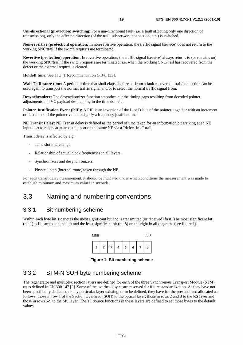
Within each byte bit 1 denotes the most significant bit and is transmitted (or received) first. The most significant bit (bit 1) is illustrated on the left and the least significant bit (bit 8) on the right in all diagrams (see figure 1).
1 2 3 4 5 6 7 8
MSB LSB
Figure 1: Bit numbering scheme
3.3.2 STM-N SOH byte numbering scheme
The regenerator and multiplex section layers are defined for each of the three Synchronous Transport Module (STM) rates defined in EN 300 147 [2]. Some of the overhead bytes are reserved for future standardization. As they have not been specifically dedicated to any particular layer existing, or to be defined, they have for the present been allocated as follows: those in row 1 of the Section Overhead (SOH) to the optical layer; those in rows 2 and 3 to the RS layer and those in rows 5-9 to the MS layer. The TT source functions in these layers are defined to set those bytes to the default values.

ETSI
ETSI EN 300 417-1-1 V1.2.1 (2001-10)20
The location of those SOH bytes within an STM-N frame is identified by a two co-ordinate vector (ROW, COL) where ROW represents the row number (1.....9) and COL represents the column co-ordinate (1....9*N). Figure 2 shows the SOH byte positions in an STM-N frame.
NOTE: A three co-ordinate vector S(a,b,c) could be used (but is not recommended) with the following relation: ROW = a, COL = N (b-1) + c, a = ROW, b = COL div N, c = COL mod N.
1 2 3 4 9N123456789
COL coordinates
ROWcoordinates
Figure 2: SOH byte numbering in a STM-N frame
3.3.3 Atomic function naming scheme
The naming of adaptation, trail termination and connection functions follow the following rules:
Adaptation function <layer>/<client layer>_A[ _<direction>]
Trail Termination function <layer>_TT[ _<direction>]
Connection function <layer>_C
Examples are: MS1/S4_A, S12/P12s_A_So, P4e_TT, RS16_TT_Sk, S3_C.
3.3.4 Information naming scheme
The coding of the CI and Adapted Information (AI) in the model follows the following rules:
<layer>[/<client layer>] _<information type>[ _<direction>] _<signal type>[/<number>].
[... ] optional term <layer> represents one of the layer names (e.g. RS1) <client layer> represents one of the client layer names (e.g. MS1 is a client of RS1) <information type> CI or AI <direction> So (Source) or Sk (Sink) <signal type> CK (clock), or
D (data), or FS (Frame Start), or SSF (Server Signal Fail), or TSF (Trail Signal Fail) SSD (Server Signal Degrade) TSD (Trail Signal Degrade)
<number> see below
AI and CI coding examples are: MS1_CI_D, RS16_AI_CK, S12/P12x_AI_D, S4/S2_AI_So_D/(2,3,0).
The coding of the MI signals is for further study. As a working solution the following rule is followed:
<atomic function>_MI_<MI signal type>.
The coding of the TI signals is for further study. As a working solution the following rule is followed:
<layer>_TI_<TI signal type: CK or FS>.

ETSI
ETSI EN 300 417-1-1 V1.2.1 (2001-10)21
NOTE 1: Most of the adaptation functions have co-directional interfaces (ITU-T Recommendation G.703 [21], clause 1.1.4.1). Contra-directional interfaces (ITU-T Recommendation G.703 [21], clause 1.1.4.3) can be found at the boundaries with "auxiliary" transmission network layers; e.g. RS to DCC.
NOTE 2: Adaptation source functions (functionally) perform the adaptation of a signal from one clock domain to another and/or from one frame phase domain to another. XX_TI_CK and XX_TI_FS represent those other clock and frame start signals. For example MS1_TI_FS, S12_TI_CK. Refer also to clause 10.
The coding of the RI signals follows the following rule:
<layer>_RI_<RI signal type>.
3.3.5 AU/TU numbering scheme
3.3.5.1 AU numbering scheme
An STM-N frame comprises Nx270 columns (numbered 1 to Nx270). The first Nx9 columns contain the SOH and AU-4/AU-4-Xc pointer(s) with the remaining Nx261 columns containing the higher order data payload (higher order tributaries).
The higher order payload columns may be addressed by means of a two (B,A), three (C,B,A) or four (D,C,B,A) figure address, where A represents the AU3 number, B the AUG-1 number, C the AUG-4 number and D the AUG-16 number. Refer to figures 3 to 8.
In order to provide a simple and convenient means of determining the total tributary capacity, i.e. the number of higher order tributaries provided, the higher order payload columns are allocated a higher order Time Slot number. The number of higher order time slots per higher order tributary in each STM-N frame is determined by the higher order payload configuration.
Numbering of AU-4s (VC-4s) in a STM-64
The STM-64 can comprise four AUG-16s, which shall be numbered #1 to #4:
- AUG-16 #1 is accommodated in columns 1..16, 65..80, 129..144, etc of the STM-64;
- AUG-16 #2 is accommodated in columns 17..32, 81..96, 145..160, etc of the STM-64;
- AUG-16 #3 is accommodated in columns 33..48, 97..112, 161..176, etc of the STM-64.
- AUG-16 #4 is accommodated in columns 49..64, 113..128, 177..192, etc of the STM-64.
Each AUG-16 can comprise four AUG-4s, which shall be numbered #1 to #4. Each AUG-4 can comprise four AUG-1s, which shall be numbered #1 to #4. Each AUG-1 can comprise three AU-3s, which shall be numbered #1 to #3.
NOTE: AU-3s are not supported within ETSI.
Therefore, any AU-4 can be allocated a number in the form #D, #C, #B, #A, where D designates the AUG-16 number (1 to 4), C designates the AUG-4 number (1 to 4), B designates the AUG-1 number (1 to 4), and A is always 0. The location of the columns in the STM-64 occupied by AU-4 (D,C,B,0) is given by:
Xth column = 1 + 16*[D-1] + 4*[C-1] + [B-1] + 64*[X-1] for X=1 to 270.
Therefore, AU-4 (1,1,1,0) resides in columns 1,65,129,193,..17 217 of the STM-64, and AU-4 (4,4,4,0) resides in columns 64,128,192,..,17 280 of the STM-64.

ETSI
ETSI EN 300 417-1-1 V1.2.1 (2001-10)22
1110
1
1120
2
1130
3
1140
4
1210
5
1220
6
1230
7
1240
8
1310
9
1320
10
1330
11
1340
12
1410
13
1420
14
1430
15
1440
16
2110
17
2120
18
2130
19
2140
20
2210
21
2220
22
2230
23
2240
24
2310
25
2320
26
2330
27
2340
28
2410
29
2420
30
2430
31
2440
32
3110
33
3120
34
3130
35
3140
36
3210
37
3220
38
3230
39
3240
40
3310
41
3320
42
3330
43
3340
44
3410
45
3420
46
3430
47
3440
48
4110
49
4120
50
4130
51
4140
52
4210
53
4220
54
4230
55
4240
56
4310
57
4320
58
4330
59
4340
60
4410
61
4420
62
4430
63
4440
64
DCBA
1110
1
1120
2
1130
3
1140
4
1210
5
Address
Time Slotnumber
STM-Ncolumnnumber
4340
60
4410
61
4420
62
4430
63
4440
64
1728
0
1 2 3 4 5 6 7 8 9 65
Figure 3: AU-4 numbering scheme within an STM-64's AU pointer row and payload columns
Numbering of AU-4-4cs (VC-4-4cs) in a STM-64
Similarly, any AU-4-4c can be allocated a four figure address in the form #D, #C, #B, #A, where D designates the AUG-16 number (1 to 4), C designates the AUG-4 number (1 to 4), B and A always 0. The location of the columns in the STM-64 occupied by AU-4-4c (D,C,0,0) is given by:
Xth column = [X mod 4] + 16*[D-1] + 4*[C-1] + 64*[X DIV 4] for X = 1 to 1 080.
Therefore, AU-4-4c (1,1,0,0) resides in columns 1,2,3,4,65,66,67,68,129,130,131,132,..,17 217,17 218, 17 219,17 220 of the STM-64, and AU-4-4c (4,4,0,0) resides in columns 61,62,63,64,125,126,127,128,..., 17 277,17 278,17 279,17 280 of the STM-64.
1100
1
1100
1
1100
1
1100
1
1200
2
1200
2
1200
2
1200
2
1300
3
1300
3
1300
3
1300
3
1400
4
1400
4
1400
4
1400
4
2100
5
2100
5
2100
5
2100
5
2200
6
2200
6
2200
6
2200
6
2300
7
2300
7
2300
7
2300
7
2400
8
2400
8
2400
8
2400
8
3100
9
3100
9
3100
9
3100
9
3200
10
3200
10
3200
10
3200
10
3300
11
3300
11
3300
11
3300
11
3400
12
3400
12
3400
12
3400
12
4100
13
4100
13
4100
13
4100
13
4200
14
4200
14
4200
14
4200
14
4300
15
4300
15
4300
15
4300
15
4400
16
4400
16
4400
16
4400
16
DCBA
1100
1
1100
1
1100
1
1100
1
1200
2
Address
Time Slotnumber
STM-Ncolumnnumber
4300
15
4400
16
4400
16
4400
16
4400
16
1728
0
1 2 3 4 5 6 7 8 9 65
Figure 4: AU-4-4c numbering scheme within an STM-64's AU pointer row and payload columns
Numbering of AU-4-16cs (VC-4-16cs) in a STM-64
Similarly, any AU-4-16c can be allocated a four figure address in the form #D, #C, #B, #A, where D designates the AUG-16 number (1 to 4), C, B and A always 0. The location of the columns in the STM-64 occupied by AU 4-16c (D,0,0,0) is given by:
Xth column = [X mod 16] + 16*[D-1] + 64*[X DIV 16] for X = 1 to 4 320.
Therefore, AU-4-16c(1,0,0,0) resides in columns 1..16, 65..80,..,17 205..17 220 of the STM-64, and AU-4-16c (4,0,0,0) resides in columns 49..64, 113..128,.., 17 265..17 280 of the STM-64.
1000
1
1000
1
1000
1
1000
1 2 2 2 2 3 3 3 3 4 4 4 4
2000
2000
2000
2000
3000
3000
3000
3000
4000
4000
4000
4000
DCBA
1 1 1 1
Address
Time Slotnumber
STM-Ncolumnnumber
1728
0
1 2 3 4 5 6 7 8 9 65
1000
1000
1000
1000
1000
1000
1000
1000
1000
1000
1000
1000
2000
2000
2000
2000
2000
2000
2000
2000
2000
2000
2000
2000
3000
3000
3000
3000
3000
3000
3000
3000
3000
3000
3000
3000
4000
4000
4000
4000
4000
4000
4000
4000
4000
4000
4000
4000
4000
4000
4000
4000
4000
1000
1000
1000
1000
1000
4 4 4 44 4 4 44 4 4 4 4 4 4 443 3 3 33 3 3 33 3 3 32 2 2 22 2 2 22 2 2 21 1 1 1 1 1 1 1 1 1 1 1 1
Figure 5: AU-4-16c numbering scheme within an STM-64's AU pointer row and payload columns
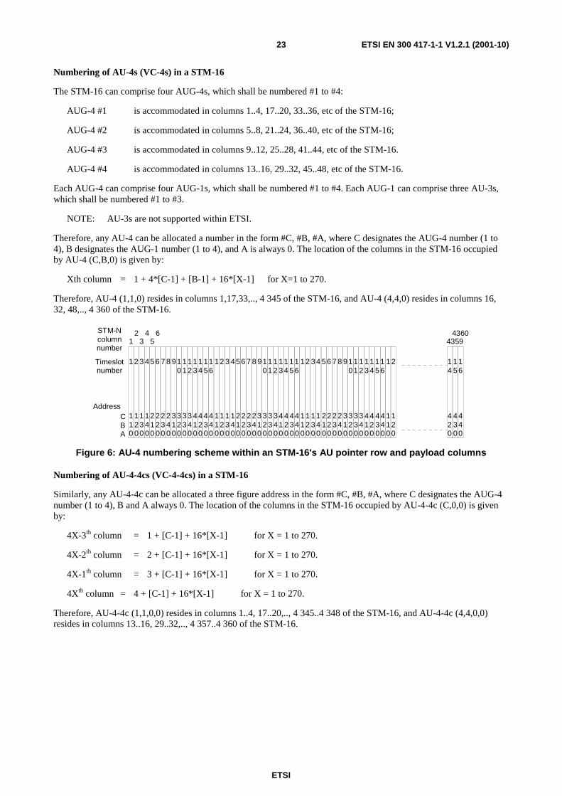
ETSI
ETSI EN 300 417-1-1 V1.2.1 (2001-10)23
Numbering of AU-4s (VC-4s) in a STM-16
The STM-16 can comprise four AUG-4s, which shall be numbered #1 to #4:
AUG-4 #1 is accommodated in columns 1..4, 17..20, 33..36, etc of the STM-16;
AUG-4 #2 is accommodated in columns 5..8, 21..24, 36..40, etc of the STM-16;
AUG-4 #3 is accommodated in columns 9..12, 25..28, 41..44, etc of the STM-16.
AUG-4 #4 is accommodated in columns 13..16, 29..32, 45..48, etc of the STM-16.
Each AUG-4 can comprise four AUG-1s, which shall be numbered #1 to #4. Each AUG-1 can comprise three AU-3s, which shall be numbered #1 to #3.
NOTE: AU-3s are not supported within ETSI.
Therefore, any AU-4 can be allocated a number in the form #C, #B, #A, where C designates the AUG-4 number (1 to 4), B designates the AUG-1 number (1 to 4), and A is always 0. The location of the columns in the STM-16 occupied by AU-4 (C,B,0) is given by:
Xth column = 1 + 4*[C-1] + [B-1] + 16*[X-1] for X=1 to 270.
Therefore, AU-4 (1,1,0) resides in columns 1,17,33,.., 4 345 of the STM-16, and AU-4 (4,4,0) resides in columns 16, 32, 48,.., 4 360 of the STM-16.
110
1
120
2
130
3
140
4
210
5
220
6
230
7
240
8
310
9
320
10
330
11
340
12
410
13
420
14
430
15
440
16
110
120
130
140
210
220
230
240
310
320
330
340
410
420
430
440
110
120
130
140
210
220
230
240
310
320
330
340
410
420
430
440
CBA
12
34
56 4360
4359
STM-Ncolumnnumber
Timeslotnumber
Address110
1
120
2
420
14
430
15
440
16
1 2 3 4 5 6 7 8 9 10
11
12
13
14
15
16
1 2 3 4 5 6 7 8 9 10
11
12
13
14
15
16
Figure 6: AU-4 numbering scheme within an STM-16's AU pointer row and payload columns
Numbering of AU-4-4cs (VC-4-4cs) in a STM-16
Similarly, any AU-4-4c can be allocated a three figure address in the form #C, #B, #A, where C designates the AUG-4 number (1 to 4), B and A always 0. The location of the columns in the STM-16 occupied by AU-4-4c (C,0,0) is given by:
4X-3th column = 1 + [C-1] + 16*[X-1] for X = 1 to 270.
4X-2th column = 2 + [C-1] + 16*[X-1] for X = 1 to 270.
4X-1th column = 3 + [C-1] + 16*[X-1] for X = 1 to 270.
4Xth column = 4 + [C-1] + 16*[X-1] for X = 1 to 270.
Therefore, AU-4-4c (1,1,0,0) resides in columns 1..4, 17..20,.., 4 345..4 348 of the STM-16, and AU-4-4c (4,4,0,0) resides in columns 13..16, 29..32,.., 4 357..4 360 of the STM-16.

ETSI
ETSI EN 300 417-1-1 V1.2.1 (2001-10)24
100
1
100
1
100
1
100
1
200
2
200
2
200
2
200
2
300
3
300
3
300
3
300
3
400
4
400
4
400
4
400
4
100
100
100
100
200
200
200
200
300
300
300
300
400
400
400
400
100
100
100
100
200
200
200
200
300
300
300
300
400
400
400
400
CBA
12
34
56 4 360
4 359
STM-Ncolumnnumber
Timeslotnumber
Address100
100
400
4
400
4
400
41 1 1 1 2 2 2 2 3 3 3 3 4 4 4 4 1 1 1 1 2 2 2 2 3 3 3 3 4 4 4 4 1 1
Figure 7: AU-4-4c numbering scheme within an STM-16's AU pointer row and payload columns
Numbering of AU-4s (VC-4s) in a STM-4
The STM-4 can comprise four AUG-1s, which shall be numbered #1 to #4:
AUG-1 #1 is accommodated in columns 1,5,9,etc of the STM-4;
AUG-1 #2 is accommodated in columns 2,6,10,etc of the STM-4;
AUG-1 #3 is accommodated in columns 3,7,11,etc of the STM-4;
AUG-1 #4 is accommodated in columns 4,8,12,etc of the STM-4.
Each AUG-1 can comprise three AU-3s, which shall be numbered #1 to #3.
NOTE: AU-3s are not supported within ETSI.
Therefore, any AU-4 can be allocated a number in the form #B, #A, where B designates the AUG-1 number (1 to 4), and A is always 0. The location of the columns in the STM-4 occupied by AU-4 (B,0) is given by:
Xth column = 1 + [B-1] + 4*[X-1] for X=1 to 270.
Therefore, AU-4 (1,0) resides in columns 1,5,9,.., 1 077 of the STM-4, and AU-4 (4,0) resides in columns 4,8,12,.. 1 080 of the STM-4.
10
1
20
2
30
3
40
4
10
20
30
40
10
20
30
40
BA
12
34
56 1 080
1 079
STM-Ncolumnnumber
Timeslotnumber
Address
2 3 4
20
30
40
10
1
20
21 2 3 4 1 2 3 4
Figure 8: AU-4 numbering scheme within an STM-4's AU pointer row and payload columns
Numbering of AU-4 (VC-4) in an STM-1 signal, AU-4-4c in an STM-4, AU-4-16c in an STM-16
There is one AU-4 (VC-4) in an STM-1 signal. There is one AU-4-4c in an STM-4 signal. There is one AU 4 16c in an STM-16 signal. These signals do not need a number, but can be referred to as (0), (0,0), (0,0,0).
3.3.5.2 TU numbering scheme within a VC-4
A VC-4 frame comprises 261 columns (numbered 1 to 261). The first 3 columns contain the POH and fixed stuff. The next 6 columns may contain TU3 data payload or fixed stuff. The remaining 252 columns contain the lower order data payload (lower order tributaries).
The lower order payload columns may be addressed by means of a three figure address (K, L, M), where K represents the TUG-3 number, L the TUG-2 number, and M the TU-1 number. Refer to figure 9.

ETSI
ETSI EN 300 417-1-1 V1.2.1 (2001-10)25
In order to provide a simple and convenient means of determining the total tributary capacity, i.e. the number of lower order tributaries provided, the lower order payload columns are allocated a Time Slot number. The number of time slots per tributary in each frame is determined by the payload configuration.
Time Slots (TSs) within the VC-4 payload are numbered from left to right in the VC-4 as shown in figure 9. For TU-12s, TS1 starts in column 10, TS2 in column 11, and so on until TS63 is in column 72. For TU-2s, TS1 starts in column 10, TS2 in column 11, and... TS21 in column 30. For TU-3s, TS1 starts in column 4, TS2 in column 5, and TS3 in column 6.
NOTE: The TS number contained in figure 9 should not be interpreted as the tributary port number. Refer to annex D.
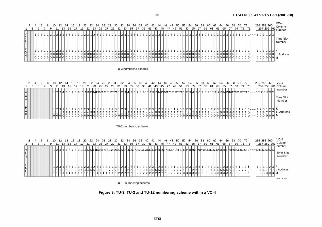
ETSI
ETSI EN 300 417-1-1 V1.2.1 (2001-10)26
1
100
2
200
3
300
1
100
2
200
3
300
1
100
2
200
3
300
1
100
2
200
3
300
1
100
2
200
3
300
1
100
2
200
3
300
1
100
2
200
3
300
1
100
2
200
3
300
1
100
2
200
3
300
1
100
2
200
3
300
1
100
2
200
3
300
1
100
2
200
3
300
1
100
2
200
3
300
1
100
2
200
3
300
1
100
2
200
3
300
1
100
2
200
3
300
1
100
2
200
3
300
1
100
2
200
3
300
1
100
2
200
3
300
1
100
2
200
3
300
1
100
2
200
3
300
1
100
2
200
3
300
1
100
2
200
3
300
12
34
56
78
910
1112
1314
1516
1718
1920
2122
2324
2526
2728
2930
3132
3334
3536
3738
3940
4142
4344
4546
4748
4950
5152
5354
5556
5758
5960
6162
6364
6566
6768
6970
7172
73
1
100
2
200
3
300
1
100
2
200
3
300
256257
258259
260261
1
100
1 2 3 4 5 6 7 8 9 101112131415161718192021
12
34
56
78
910
1112
1314
1516
1718
1920
2122
2324
2526
2728
2930
3132
3334
3536
3738
3940
4142
4344
4546
4748
4950
5152
5354
5556
5758
5960
6162
6364
6566
6768
6970
7172
73256
257258
259260
261
12
34
56
78
910
1112
1314
1516
1718
1920
2122
2324
2526
2728
2930
3132
3334
3536
3738
3940
4142
4344
4546
4748
4950
5152
5354
5556
5758
5960
6162
6364
6566
6768
6970
7172
73256
257258
259260
261
110
210
310
120
220
320
130
230
330
140
240
340
150
250
350
160
260
360
170
270
370
1 2 3 4 5 6 7 8 9 101112131415161718192021
110
210
310
120
220
320
130
230
330
140
240
340
150
250
350
160
260
360
170
270
370
1 2 3 4 5 6 7 8 9 101112131415161718192021
110
210
310
120
220
320
130
230
330
140
240
340
150
250
350
160
260
360
170
270
370
1
100
161718192021
160
260
360
170
270
370
1 2 3 4 5 6 7 8 9 101112131415161718192021
11
21
31
12
22
32
13
23
33
14
24
34
15
25
35
16
26
36
17
27
37
1 1 1 1 1 1 1 1 1 1 1 1 1 1 1 1 1 1 1 1 1
222324252627282930313233343536373839404142
11
21
31
12
22
32
13
23
33
14
24
34
15
25
35
16
26
36
17
27
37
2 2 2 2 2 2 2 2 2 2 2 2 2 2 2 2 2 2 2 2 2
434445464748495051525354555657585960616263
11
21
31
12
22
32
13
23
33
14
24
34
15
25
35
16
26
36
17
27
37
3 3 3 3 3 3 3 3 3 3 3 3 3 3 3 3 3 3 3 3 3
1
100
585960616263
16
26
36
17
27
37
3 3 3 3 3 3
T1518140-95
TU-3 numbering scheme
TU-2 numbering scheme
TU-12 numbering scheme
KL AddressM
Time Slot Number
VC-4Column number
VC-4Column number
Time Slot Number
KL AddressM
KL AddressM
Time SlotNumber
VC-4Column number
VC4
POH
VC4
POH
VC4
POH
Figure 9: TU-3, TU-2 and TU-12 numbering scheme within a VC-4
ETSI
ETSI EN 300 417-1-1 V1.2.1 (2001-10)27
Numbering of TU-12s (VC-12s) in a VC-4
The VC-4 can comprise three TUG-3s which shall be numbered #1, #2, and #3:
TUG-3 #1 (corresponding to TUG-3 (A) in figure 2.4/G.709) is accommodated in columns 4, 7, 10,..., 259 of the VC-4;
TUG-3 #2 (corresponding to TUG-3 (B) in figure 2.4/G.709) is accommodated in columns 5, 8, 11,..., 260 of the VC-4;
TUG-3 #3 (corresponding to TUG-3 (C) in figure 2.4/G.709) is accommodated in columns 6, 9, 12,..., 261 of the VC-4.
Each TUG-3 can comprise seven TUG-2s which shall be numbered #1 to #7 and each TUG-2 can comprise three TU-12s which shall be numbered #1 to #3.
Therefore, any TU-12 can be allocated a number in the form #K, #L, #M, where K designates the TUG-3 number (1 to 3), L designates the TUG-2 number (1 to 7), and M designates the TU-12 number (1 to 3). The location of the columns in the VC-4 occupied by TU-12 (K, L, M) is given by:
Xth column = 10 + [K-1] + 3*[L-1] + 21*[M-1] + 63*[X-1] for X=1 to 4.
Therefore, TU-12(1,1,1) resides in columns 10, 73, 136, and 199 of the VC-4, and TU-12(3,7,3) resides in columns 72,135, 198 and 261 of the VC-4. A full listing of the location of the TU-12 columns with the VC-4 frame is given in annex E.
Numbering of TU-2s (VC-2s) in a VC-4
Similarly, any TU-2 can be allocated a three figure address in the form #K, #L, #M, where K designates the TUG-3 number (1 to 3), L designates the TUG-2 number (1 to 7), and M is always 0. The location of the columns in the VC-4 occupied by TU-2 (K, L, 0) is given by:
Xth column = 10 + [K-1] + 3*[L-1] + 21*[X-1] for X = 1 to 12.
Therefore, TU-2(1,1,0) resides in columns 10, 31, 52, 73, 94, 115, 136, 157, 178, 199, 220 and 241 of the VC-4, and TU-2(3,7,0) resides in columns 30, 51, 72, 93, 114, 135, 156, 177, 198, 219, 240 and 261 of the VC-4. A full listing of the location of the TU-2 columns with the VC-4 frame is given in annex E.
Numbering of TU-3s (VC-3s) in a VC-4
Similarly, any TU-3 can be allocated a three figure address in the form #K, #L, #M, where K designates the TUG-3 number (1 to 3), L and M are always 0. The location of the columns in the VC-4 occupied by TU-3 (K,0,0) is given by the formula:
Xth column = 4 + [K-1] + 3*[X-1] for X = 1 to 86.
Therefore, TU-3(1,0,0) resides in columns 4, 7, 10,..., 259 of the VC-4, and TU-3(3,0,0) resides in columns 6, 9, 12,..., 261 of the VC-4.
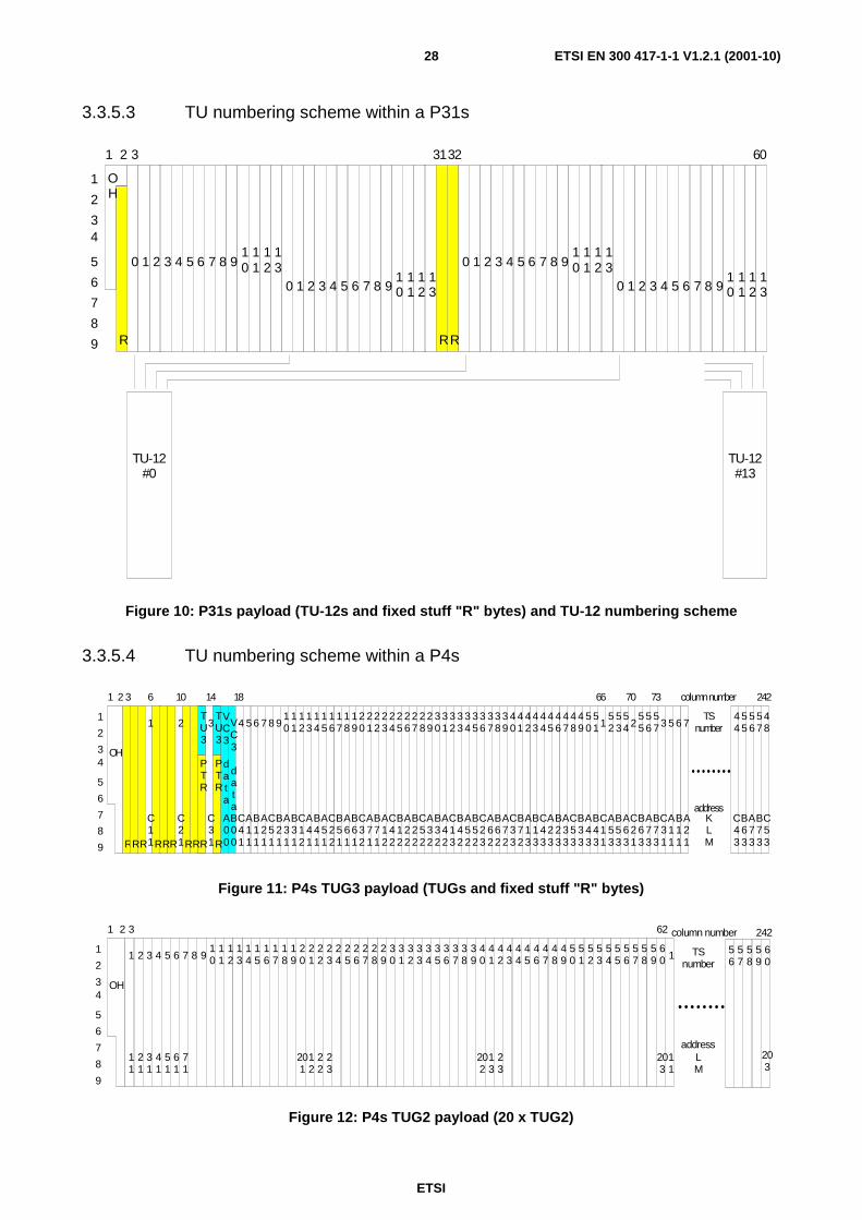
ETSI
ETSI EN 300 417-1-1 V1.2.1 (2001-10)28
3.3.5.3 TU numbering scheme within a P31s
R
0 1 2 3 4 5 6 7 8 910
11
12
13
0 1 2 3 4 5 6 7 8 910
11
12
13
OH
RR
0 1 2 3 4 5 6 7 8 910
11
12
13
0 1 2 3 4 5 6 7 8 910
11
12
13
1
2
34
5
6
7
8
9
1 2 3 3132 60
TU-12#0
TU-12#13
Figure 10: P31s payload (TU-12s and fixed stuff "R" bytes) and TU-12 numbering scheme
3.3.5.4 TU numbering scheme within a P4s
R
OH
1
2
34
5
6
7
8
9
1 2 3 66
C11
C21
C31
C41
TU3
PTR
TU3
PTR
VC3
data
VC3
data
A11
B11
A21
C51
B21
A31
B31
C12
A41
B41
A51
C22RR RRR RRR
1 2 3 4 56 7 8 910
11
12
13
14
15
16
17
18
19
20
21
22
23
24
25
26
27
28
29
30
31
32
33
34
35
36
37
38
39
40
41
42
43
44
45
46
B51
A61
B61
C32
A71
B71
A12
C42
B12
A22
B22
C52
A32
B32
A42
C13
B42
A52
B52
C23
A62
B62
A72
C33
B72
A13
B13
C43
A23
B23
47
48
49
50
51
52
53
54
55
56
57
A33
C53
B33
A43
B43
C11
A53
B53
A63
C21
B63
A73
B73
C31
A11
B11
1 2 3 5 6
A21
7
6 10 14 18 70 73
TSnumber
KLM
address
column number
55
56
57
C43
B63
A73
B73
C53
44
48
242
A00
B00R
Figure 11: P4s TUG3 payload (TUGs and fixed stuff "R" bytes)
OH
1
2
34
5
6
7
8
9
1 2 3
1 2 3 4 5 6 7 8 910
11
12
13
14
15
16
17
18
19
20
21
22
23
24
25
26
27
28
29
30
31
32
33
34
35
36
37
38
39
40
41
42
43
44
45
46
47
48
49
50
51
52
53
54
55
56
57
58
59
60 1 TS
number
LM
address
column number
58
56
57
203
59
60
24262
11
21
31
41
51
61
71
201
12
22
23
202
13
23
203
11
Figure 12: P4s TUG2 payload (20 x TUG2)

ETSI
ETSI EN 300 417-1-1 V1.2.1 (2001-10)29
3.3.6 Reference points numbering scheme
The Access Point (AP) number is used to uniquely identify an AP.
The Termination Connection Point (TCP) number is the AP number associated with the trail termination function.
The Connection Point (CP) number is the AP number associated with the connected adaptation function, extended with the multiplex number, e.g. the AU or TU number.
3.3.7 Tributary port numbering scheme
The tributary port numbering is for further study.
3.3.8 PU numbering scheme
Numbering of PU12 (2 Mbit/s) signals in an 8 448 kbit/s signal
According to ITU-T Recommendation G.742 [24], the 8 448 kbit/s signal comprises four PU12 (2 Mbit/s) signals, which shall be numbered #1, #2, #3, and #4 (figure 13):
- PU12 #1 is accommodated in column 1 rows 4 to 212 of the 8 448 kbit/s;
- PU12 #2 is accommodated in column 2 rows 4 to 212 of the 8 448 kbit/s;
- PU12 #3 is accommodated in column 3 rows 4 to 212 of the 8 448 kbit/s;
- PU12 #4 is accommodated in column 4 rows 4 to 212 of the 8 448 kbit/s.
Numbering of PU22 (8 Mbit/s) signals in an 34 368 kbit/s signal
According to ITU-T Recommendation G.751 [25], the 34 368 kbit/s signal comprises four PU22 (8 Mbit/s) signals, which shall be numbered #1, #2, #3, and #4 (figure 13):
- PU22 #1 is accommodated in column 1 rows 4 to 384 of the 34 368 kbit/s;
- PU22 #2 is accommodated in column 2 rows 4 to 384 of the 34 368 kbit/s;
- PU22 #3 is accommodated in column 3 rows 4 to 384 of the 34 368 kbit/s;
- PU22 #4 is accommodated in column 4 rows 4 to 384 of the 34 368 kbit/s.
Numbering of PU31 (34 Mbit/s) signals in an 139 264 kbit/s signal
According to ITU-T Recommendation G.751 [25], the 139 264 kbit/s signal comprises four PU31 (34 Mbit/s) signals, which shall be numbered #1, #2, #3, and #4 (figure 13):
- PU31 #1 is accommodated in column 1 rows 5 to 732 of the 139 264 kbit/s;
- PU31 #2 is accommodated in column 2 rows 5 to 732 of the 139 264 kbit/s;
- PU31 #3 is accommodated in column 3 rows 5 to 732 of the 139 264 kbit/s;
- PU31 #4 is accommodated in column 4 rows 5 to 732 of the 139 264 kbit/s.
NOTE: In contrast to SDH, PDH multiplexed signals are bit rather than byte interleaved.
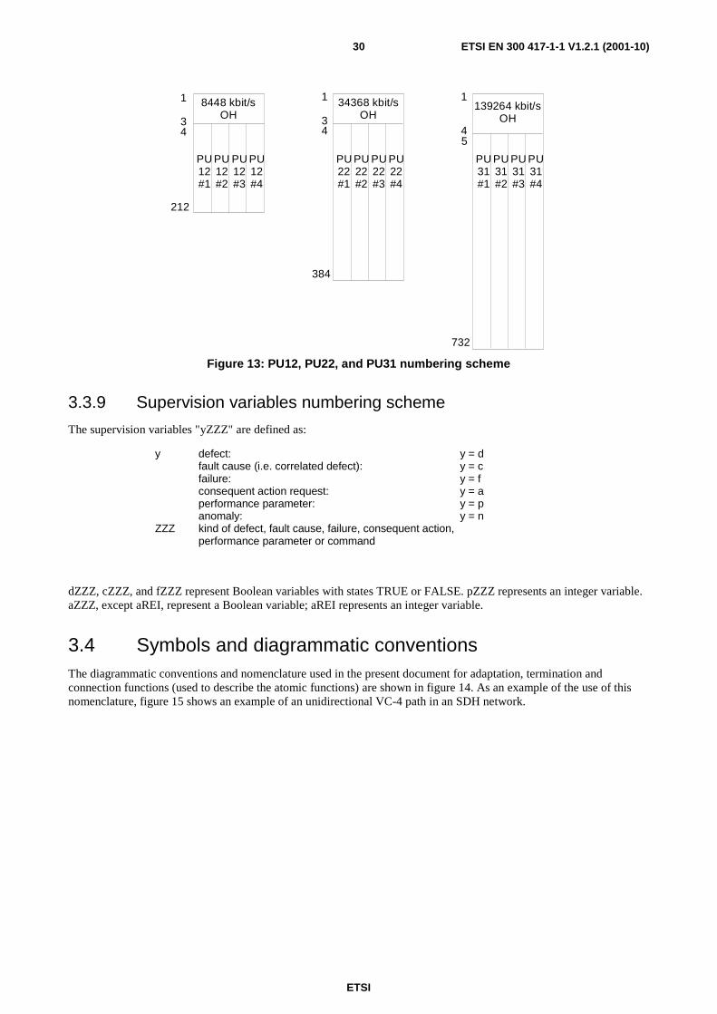
ETSI
ETSI EN 300 417-1-1 V1.2.1 (2001-10)30
8448 kbit/sOH
1
34
212
PU12#1
PU12#2
PU12#3
PU12#4
34368 kbit/sOH
PU22#1
PU22#2
PU22#3
PU22#4
139264 kbit/sOH
PU31#1
PU31#2
PU31#3
PU31#4
1
34
384
1
54
732
Figure 13: PU12, PU22, and PU31 numbering scheme
3.3.9 Supervision variables numbering scheme
The supervision variables "yZZZ" are defined as:
y defect: y = d fault cause (i.e. correlated defect): y = c failure: y = f consequent action request: y = a performance parameter: y = p anomaly: y = n ZZZ kind of defect, fault cause, failure, consequent action,
performance parameter or command
dZZZ, cZZZ, and fZZZ represent Boolean variables with states TRUE or FALSE. pZZZ represents an integer variable. aZZZ, except aREI, represent a Boolean variable; aREI represents an integer variable.
3.4 Symbols and diagrammatic conventions The diagrammatic conventions and nomenclature used in the present document for adaptation, termination and connection functions (used to describe the atomic functions) are shown in figure 14. As an example of the use of this nomenclature, figure 15 shows an example of an unidirectional VC-4 path in an SDH network.
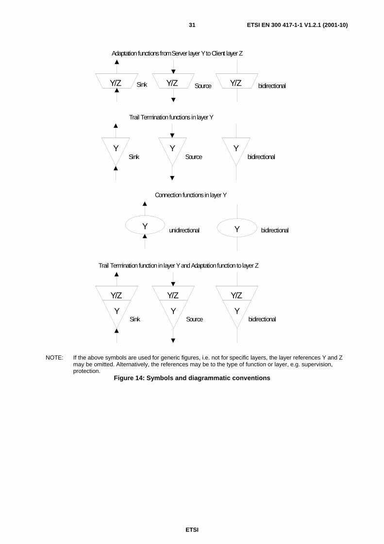
ETSI
ETSI EN 300 417-1-1 V1.2.1 (2001-10)31
Sink
Sink
Source
Source bidirectional
bidirectional
bidirectionalunidirectional
Adaptation functions from Server layer Y to Client layer Z
Y/Z Y/Z Y/Z
Y Y Y
Trail Termination functions in layer Y
Connection functions in layer Y
YY
Y/Z
Y
Y/Z
Y
Y/Z
YbidirectionalSourceSink
Trail Termination function in layer Y and Adaptation function to layer Z
NOTE: If the above symbols are used for generic figures, i.e. not for specific layers, the layer references Y and Z may be omitted. Alternatively, the references may be to the type of function or layer, e.g. supervision, protection.
Figure 14: Symbols and diagrammatic conventions
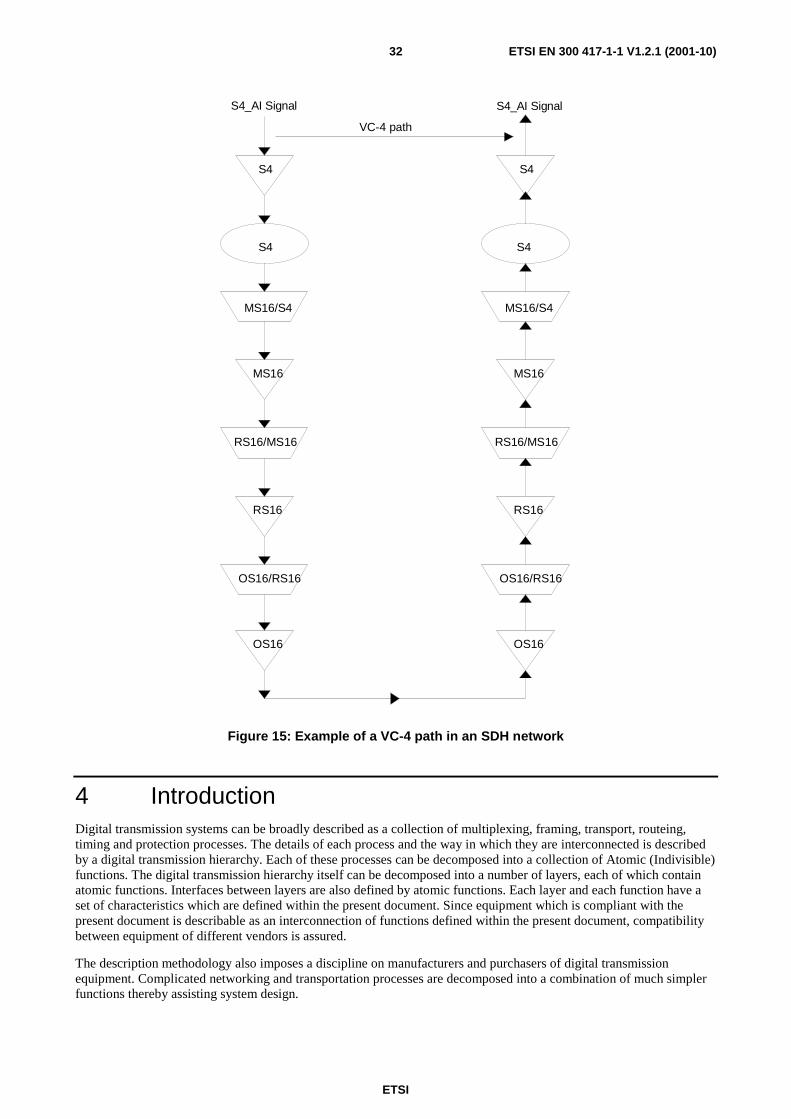
ETSI
ETSI EN 300 417-1-1 V1.2.1 (2001-10)32
S4
RS16/MS16
RS16
OS16/RS16
S4
RS16/MS16
RS16
OS16/RS16
S4_AI Signal S4_AI Signal
S4S4
MS16/S4
MS16
MS16/S4
MS16
OS16OS16
VC-4 path
Figure 15: Example of a VC-4 path in an SDH network
4 Introduction Digital transmission systems can be broadly described as a collection of multiplexing, framing, transport, routeing, timing and protection processes. The details of each process and the way in which they are interconnected is described by a digital transmission hierarchy. Each of these processes can be decomposed into a collection of Atomic (Indivisible) functions. The digital transmission hierarchy itself can be decomposed into a number of layers, each of which contain atomic functions. Interfaces between layers are also defined by atomic functions. Each layer and each function have a set of characteristics which are defined within the present document. Since equipment which is compliant with the present document is describable as an interconnection of functions defined within the present document, compatibility between equipment of different vendors is assured.
The description methodology also imposes a discipline on manufacturers and purchasers of digital transmission equipment. Complicated networking and transportation processes are decomposed into a combination of much simpler functions thereby assisting system design.

ETSI
ETSI EN 300 417-1-1 V1.2.1 (2001-10)33
The method of functional decomposition described in the following clauses and the symbols and unique names which are used to describe the atomic functions combine to form a short-hand diagrammatic notation which can be used to specify the functionality of an equipment or a network. It is intended that this short-hand notation should simplify technical descriptions and tenders since reference to the present document will give engineers a common understanding of the symbols and names used.
4.1 Functional modelling rationale A limited set of atomic functions has been derived by decomposing the European digital transmission hierarchy to form the library contained within the present document. The contents of this library are consistent with the definitions of functions contained in ITU-T Recommendation G.783 [26]. In order to be compliant with the present document, equipment which contains functionality defined within the present document should only use the functions as explicitly defined. As technology evolves, new network elements requiring additional atomic functions may be developed. These additional atomic functions, which are not contained within the present document, may be used. The use and definition of such additional functions should be submitted for standardization and inclusion within the present document at the earliest opportunity.
Three types of atomic function are required to describe a transmission network. According to ITU-T Recommendation G.803 [27], these are:
- the connection function;
- the adaptation function;
- the termination function.
Each of these functions can be unidirectional or bi-directional. The direction of transmission through an unidirectional function is identified by defining it as a sink or a source function.
4.1.1 Description of network elements - equipment functional specification
A Network Element (NE) (equipment) is described by its Equipment Functional Specification (EFS) that accommodates a list of applicable atomic functions and their interconnection scheme. A network element can be most easily and concisely specified as a collection of atomic and/or compound functions by representing these functions in diagrammatic form as stated in the present document.
The present document specifies the components and the methodology that should be used to specify SDH equipment; it does not describe an individual SDH equipment as such.
4.1.2 Implementation independence
The atomic functions and their interconnection in an EFS, describe the functionality as it can be observed from the inputs and outputs of the NE. The internal structure of the implementation of this functionality (equipment design) need not be identical to the structure of the functional model, as long as all the details of the externally observable behaviour comply with the EFS.
NOTE: One exception to this implementation independence rule is recognized. Refer to clause 5.2.1.
4.1.3 Universal representation for management
Implementation independent descriptions of network functions, such as those given in the present document, form the basis of a generic information model for digital transmission equipment (ETS 300 304 [5]). This model will be applicable to any equipment which is compliant with the present document since network control and monitoring are related to the functions contained in the library of the present document, and from which subsets of functions are drawn to describe compliant equipment. Consequently, implementation and manufacturer information is reduced to a minimum. Some manufacturer specific information is required for repair and maintenance purposes.
ETSI
ETSI EN 300 417-1-1 V1.2.1 (2001-10)34
4.2 The underlying principles of functional modelling
4.2.1 The client-server relationship
ITU-T Recommendation G.803 [27] defines a collection of layers which model the digital transmission hierarchy. Each layer is related to the adjacent layer in one of two ways. It either serves the adjacent layer or is served by the adjacent layer. When the layer serves the adjacent layer it is called a server layer and when it is served by the adjacent layer it is called a client layer. Thus, a client/server relationship is established between the layers which describe the digital transmission hierarchy. This relationship is recursive. ITU-T Recommendation G.803 [27] describes the generic properties of the layers which describe the digital transmission hierarchy and the functions from which such networks are constructed. The present document gives specific definitions for the network functions which form each layer of the European digital transmission hierarchy.
4.2.2 Atomic functions and compound functions
The main unit of equipment specification is the atomic function, which may be interconnected as discussed in clause 6. Groups of atomic functions within a library of atomic functions may be combined in accordance with the combination rules, stated in the present document, to form compound functions. Functions can also be combined across layer boundaries to form more complicated major compound functions. A number of (major) compound functions which are fundamental to the European digital transmission hierarchy are defined in the present document. These definitions are consistent with the definitions contained in ITU-T Recommendation G.783 [26] although in some cases the definitions given in the present document will contain supplementary points of detail. Equipment which is compliant with the present document can be specified by using any valid combination of these compound functions and the atomic functions defined in the present document. The mechanism by which atomic and/or compound functions are combined by binding at compatible connection and access points is defined in clause 6.
4.2.3 Network functions included in specific equipment
The grouping of atomic and/or compound functions, drawn from the libraries of these functions contained within the present document, is restricted only by the combination rules given in clause 6. There is therefore no restriction on the functions which can be included in a specific equipment. Furthermore, it is possible to specify equipment which complies with the present document and which can be configured in a number of ways to carry out different network functions.
For example: More than one adaptation function, of the same or of a different type, can be "present" in a Network Element (NE) and connected to a single termination function. For such a case, a subset of the adaptation functions may be "active" (providing service) while the others are "in-active". The signals applied to the "in-active" group of adaptation source functions are not forwarded to the termination source function. This configuration can be modified over time.
4.2.4 The functional model and the information model
The Functional Model of an equipment describes the way in which the equipment accepts, processes and forwards information contained in a signal. Thus, not only are the internal processes of the equipment specified but the internal and external interfaces are also specified. The functional model also specifies the performance criteria which shall be met by each process, and the actions which shall be taken when these performance criteria are not met. The performance of a process or interface is determined by the number and nature of the anomalies which occur within the process.
The Information Model describes an equipment from the management viewpoint as a collection of Managed Objects (MOs) which can be manipulated by a management system. These MOs are instances of the MO classes defined in ETS 300 304 [5]. These MOs, and their attributes, are expressed in a standard notation defined for this purpose (refer to ITU-T Recommendation X.721 [36]). The definition of each MO class is thus derived from a specific part of the functional model. It cannot be assumed that a one-to-one relationship exists between each function and each MO, neither should it be assumed that the functional model data is always displayed unchanged.
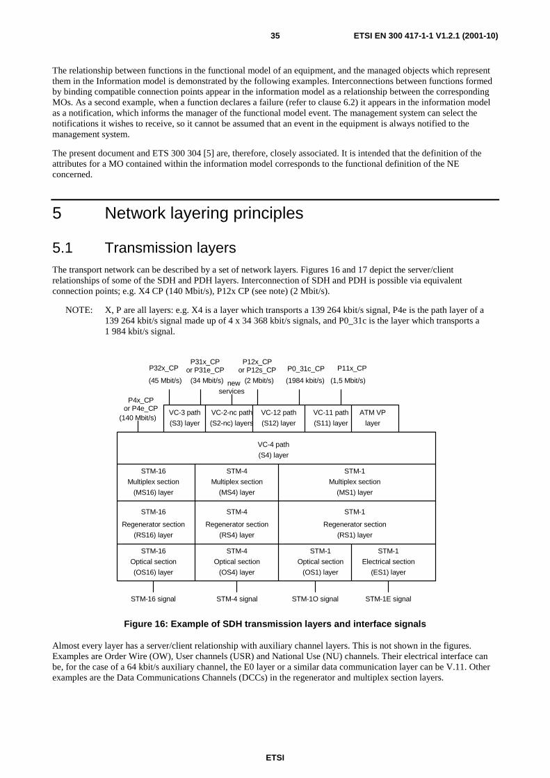
ETSI
ETSI EN 300 417-1-1 V1.2.1 (2001-10)35
The relationship between functions in the functional model of an equipment, and the managed objects which represent them in the Information model is demonstrated by the following examples. Interconnections between functions formed by binding compatible connection points appear in the information model as a relationship between the corresponding MOs. As a second example, when a function declares a failure (refer to clause 6.2) it appears in the information model as a notification, which informs the manager of the functional model event. The management system can select the notifications it wishes to receive, so it cannot be assumed that an event in the equipment is always notified to the management system.
The present document and ETS 300 304 [5] are, therefore, closely associated. It is intended that the definition of the attributes for a MO contained within the information model corresponds to the functional definition of the NE concerned.
5 Network layering principles
5.1 Transmission layers The transport network can be described by a set of network layers. Figures 16 and 17 depict the server/client relationships of some of the SDH and PDH layers. Interconnection of SDH and PDH is possible via equivalent connection points; e.g. X4 CP (140 Mbit/s), P12x CP (see note) (2 Mbit/s).
NOTE: X, P are all layers: e.g. X4 is a layer which transports a 139 264 kbit/s signal, P4e is the path layer of a 139 264 kbit/s signal made up of 4 x 34 368 kbit/s signals, and P0_31c is the layer which transports a 1 984 kbit/s signal.
STM-16
Optical section
(OS16) layer
STM-16
STM-16
Regenerator section
(RS16) layer
Multiplex section
(MS16) layer
STM-4
Optical section
(OS4) layer
STM-4
STM-4
Regenerator section
(RS4) layer
Multiplex section
(MS4) layer
STM-1
Optical section
(OS1) layer
STM-1
STM-1
Regenerator section
(RS1) layer
Multiplex section
(MS1) layer
STM-1
Electrical section
(ES1) layer
VC-4 path
(S4) layer
VC-3 path
(S3) layer
VC-2-nc path
(S2-nc) layers
VC-12 path
(S12) layer
VC-11 path
(S11) layer
ATM VP
layer(140 Mbit/s)
P4x_CPor P4e_CP
P32x_CP
(45 Mbit/s)
P31x_CPor P31e_CP
(34 Mbit/s)
STM-16 signal STM-4 signal STM-1O signal STM-1E signal
P12x_CPor P12s_CP P0_31c_CP P11x_CP
newservices
(2 Mbit/s) (1984 kbit/s) (1,5 Mbit/s)
Figure 16: Example of SDH transmission layers and interface signals
Almost every layer has a server/client relationship with auxiliary channel layers. This is not shown in the figures. Examples are Order Wire (OW), User channels (USR) and National Use (NU) channels. Their electrical interface can be, for the case of a 64 kbit/s auxiliary channel, the E0 layer or a similar data communication layer can be V.11. Other examples are the Data Communications Channels (DCCs) in the regenerator and multiplex section layers.
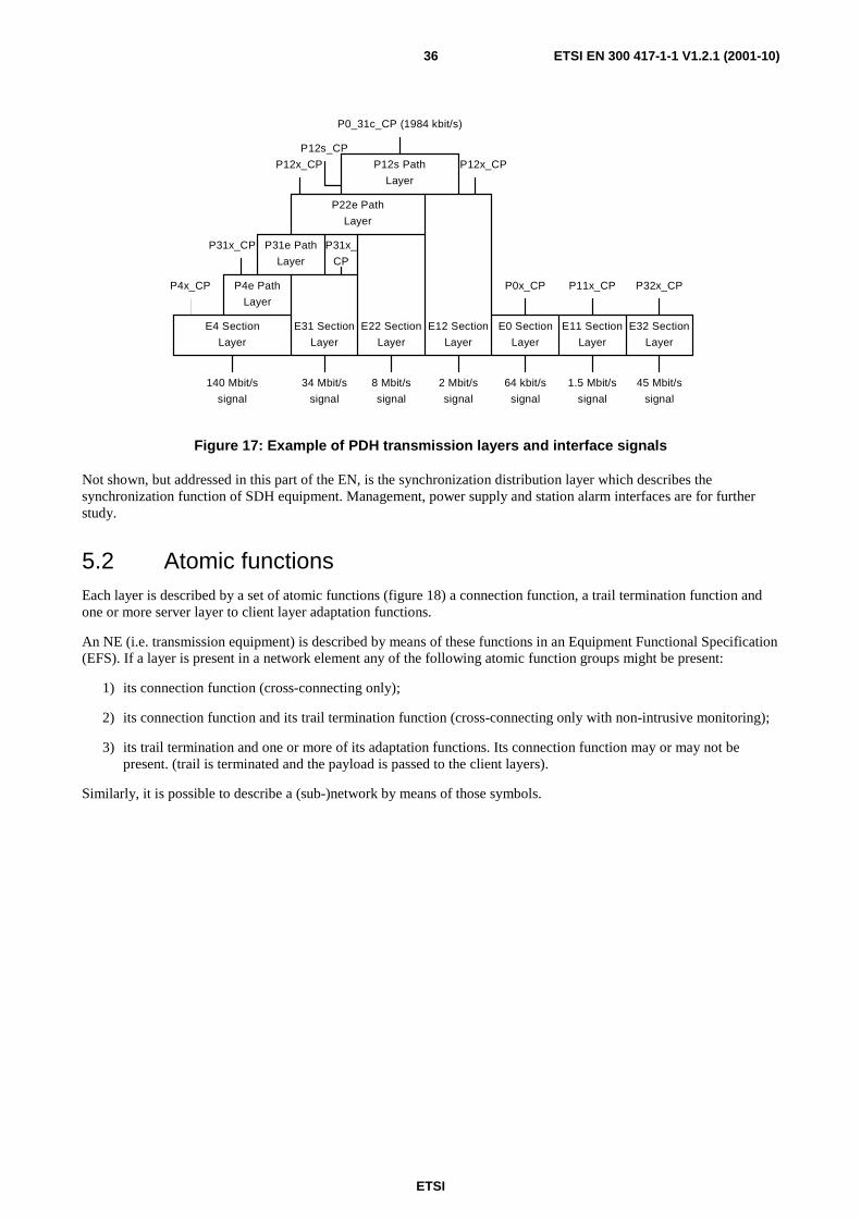
ETSI
ETSI EN 300 417-1-1 V1.2.1 (2001-10)36
E4 Section
Layer
E31 Section
Layer
P4e Path
E0 SectionE22 Section E12 Section
Layer Layer
Layer
P4x_CP
P31x_CP P31e Path
Layer
P31x_
P22e Path
Layer
P12s Path
Layer
P12x_CP
P12s_CP
P0_31c_CP (1984 kbit/s)
P12x_CP
Layer
E11 Section
Layer
P0x_CP P11x_CP
E32 Section
Layer
P32x_CP
signal
140 Mbit/s
signal
34 Mbit/s
signal
8 Mbit/s
signal
2 Mbit/s
signal
64 kbit/s
signal
1.5 Mbit/s
signal
45 Mbit/s
CP
Figure 17: Example of PDH transmission layers and interface signals
Not shown, but addressed in this part of the EN, is the synchronization distribution layer which describes the synchronization function of SDH equipment. Management, power supply and station alarm interfaces are for further study.
5.2 Atomic functions Each layer is described by a set of atomic functions (figure 18) a connection function, a trail termination function and one or more server layer to client layer adaptation functions.
An NE (i.e. transmission equipment) is described by means of these functions in an Equipment Functional Specification (EFS). If a layer is present in a network element any of the following atomic function groups might be present:
1) its connection function (cross-connecting only);
2) its connection function and its trail termination function (cross-connecting only with non-intrusive monitoring);
3) its trail termination and one or more of its adaptation functions. Its connection function may or may not be present. (trail is terminated and the payload is passed to the client layers).
Similarly, it is possible to describe a (sub-)network by means of those symbols.

ETSI
ETSI EN 300 417-1-1 V1.2.1 (2001-10)37
Layer Y to Layer ZAdaptation
Sink
Layer Y to Layer ZAdaptation
Source
TrailTermination
Sink
TrailTermination
Source
Access Point (AP)
Connection Point (CP)
Termination ConnectionPoint (TCP)
Connection Point (CP)
Remote Point(maintenance signals)
Management Point(MP)
MP
TimingPoint (TP)
uni-directional representation
Layer Y to Layer ZAdaptation
TrailTermination
ConnectionConnectionMP
Layer Y
Layer X
Layer Z
bi-directional representation
TP
Figure 18: Atomic functions in a layer
5.2.1 Connection function
The connection function provides flexibility within a layer. It may be used by the network operator to provide routeing, grooming, protection and restoration.
NOTE: The connection function's flexibility process is modelled as a "space switch". In equipment the switch matrix type may be either a "space switch" or a combination of "space and time switches". If a time switch is involved the adaptation source functionality shall be located at the input of the switch matrix (connection function) rather than at the output (as in the functional model).
The location of the adaptation source functionality (i.e. Elastic Store and Pointer Generator) with respect to the connection functionality (i.e. switch matrix) is observable at the STM-N interface when the matrix connection is changed (e.g. due to SNC protection switch). A pointer with "enabled NDF" is generated when the adaptation source functionality is located at the output of the connection functionality. A pointer without "enabled NDF" is generated when the adaptation source functionality is located at the input of the connection functionality.
5.2.2 Trail termination function
The Trail Termination function performs the signal integrity supervision of the layer. In the source direction it generates and adds some or all of the following:
- error detection code (e.g. Bit Interleaved Parity (BIP), Cyclic Redundancy Check (CRC));
- trail trace identifier (i.e. source address).
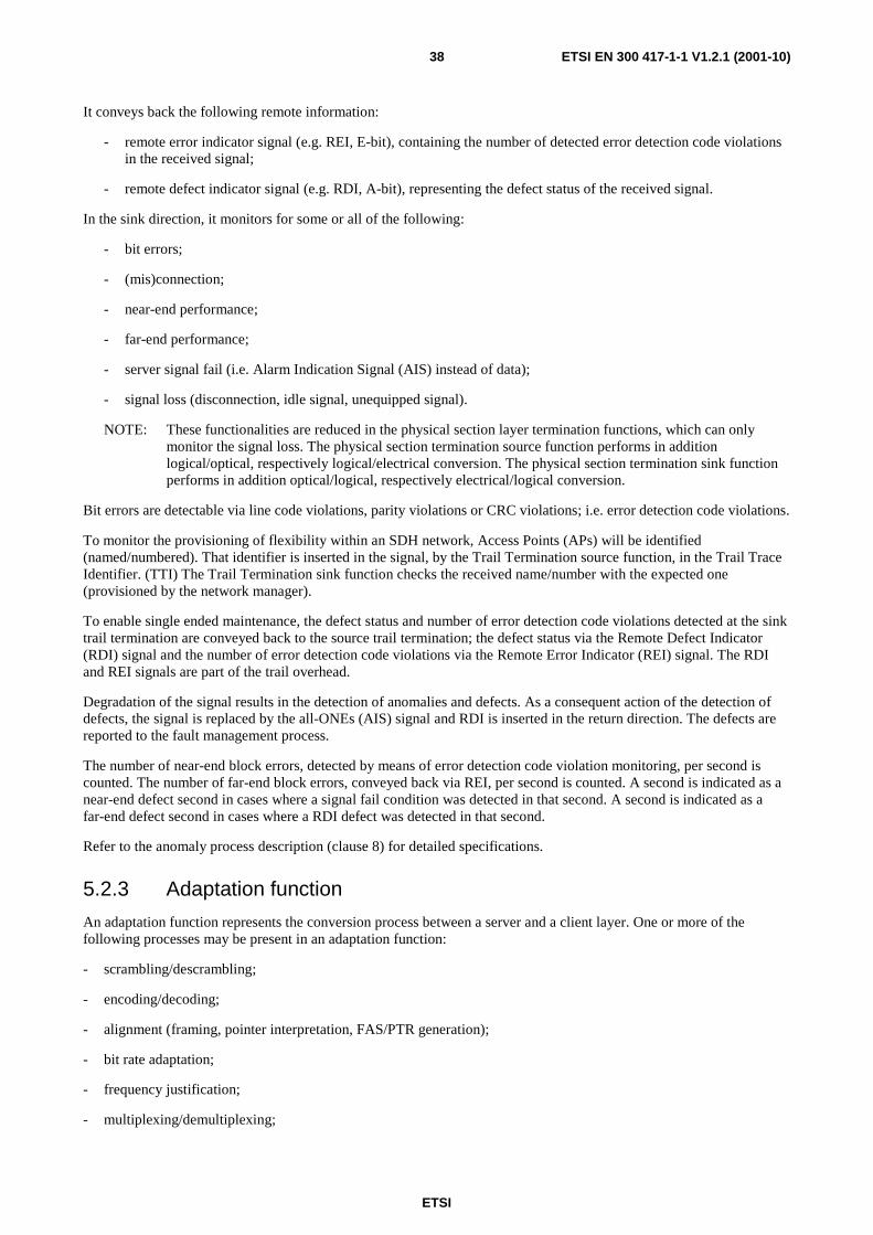
ETSI
ETSI EN 300 417-1-1 V1.2.1 (2001-10)38
It conveys back the following remote information:
- remote error indicator signal (e.g. REI, E-bit), containing the number of detected error detection code violations in the received signal;
- remote defect indicator signal (e.g. RDI, A-bit), representing the defect status of the received signal.
In the sink direction, it monitors for some or all of the following:
- bit errors;
- (mis)connection;
- near-end performance;
- far-end performance;
- server signal fail (i.e. Alarm Indication Signal (AIS) instead of data);
- signal loss (disconnection, idle signal, unequipped signal).
NOTE: These functionalities are reduced in the physical section layer termination functions, which can only monitor the signal loss. The physical section termination source function performs in addition logical/optical, respectively logical/electrical conversion. The physical section termination sink function performs in addition optical/logical, respectively electrical/logical conversion.
Bit errors are detectable via line code violations, parity violations or CRC violations; i.e. error detection code violations.
To monitor the provisioning of flexibility within an SDH network, Access Points (APs) will be identified (named/numbered). That identifier is inserted in the signal, by the Trail Termination source function, in the Trail Trace Identifier. (TTI) The Trail Termination sink function checks the received name/number with the expected one (provisioned by the network manager).
To enable single ended maintenance, the defect status and number of error detection code violations detected at the sink trail termination are conveyed back to the source trail termination; the defect status via the Remote Defect Indicator (RDI) signal and the number of error detection code violations via the Remote Error Indicator (REI) signal. The RDI and REI signals are part of the trail overhead.
Degradation of the signal results in the detection of anomalies and defects. As a consequent action of the detection of defects, the signal is replaced by the all-ONEs (AIS) signal and RDI is inserted in the return direction. The defects are reported to the fault management process.
The number of near-end block errors, detected by means of error detection code violation monitoring, per second is counted. The number of far-end block errors, conveyed back via REI, per second is counted. A second is indicated as a near-end defect second in cases where a signal fail condition was detected in that second. A second is indicated as a far-end defect second in cases where a RDI defect was detected in that second.
Refer to the anomaly process description (clause 8) for detailed specifications.
5.2.3 Adaptation function
An adaptation function represents the conversion process between a server and a client layer. One or more of the following processes may be present in an adaptation function:
- scrambling/descrambling;
- encoding/decoding;
- alignment (framing, pointer interpretation, FAS/PTR generation);
- bit rate adaptation;
- frequency justification;
- multiplexing/demultiplexing;

ETSI
ETSI EN 300 417-1-1 V1.2.1 (2001-10)39
- timing recovery;
- smoothing;
- payload identification.
The scrambling process alters digital data in a pre-defined way to ensure the resulting bit stream has a sufficient density of 0 → 1 and 1 → 0 transitions to allow bit clock recovery from it. The descrambling process recovers the original digital data from the scrambled bitstream.
NOTE: The scrambling/descrambling process would be Adaptation processes. The (historical) definition of signals in existing standards causes a violation of this process allocation, hence the scrambling/descrambling processes are often located in the Trail Termination functions. Refer to the individual atomic functions for details.
The encoding/decoding process adapts a digital data stream to the characteristics of the physical medium over which it is meant to be transported. The decoding process recovers the original digital data from the medium specific form in which it is received.
The alignment process locates the first bit/byte of the framed signal (Frame Start (FS)) by means of a search for the Frame Alignment Signal (FAS) or the interpretation of the Pointer (PTR). If the FAS can not be found or the PTR is corrupted for a specific period, an alignment defect is detected (LOF, LOP). The alignment defect may be the result of the reception of the all-ONEs (AIS) signal. If so, the AIS defect is detected also. The defects are reported to the fault management layer/process.
NOTE: The insertion of a frame alignment signal would be an A_So process. The (historical) definition of the many signals in existing standards causes a violation of this process allocation, hence the frame alignment insertion process is often located in the TT_So function. Refer to the individual atomic functions for details.
The bit-rate adaptation process accepts input information at a certain bit rate and outputs that same information at a different bit rate. In the source direction, this process creates gaps in which other adaptation functions can add their signals. An example is the S12/P12s_A_So function; the 2 Mbit/s signal input to this function is output at a higher bit rate. The created gaps will be filled with the VC-12 POH.
The frequency justification process accepts an input information at a certain frequency and outputs that same information either at the same or at a different frequency. In the source direction, in order to accommodate any frequency (and/or phase) differences between input and output signals, this process may write data into a specific "justification" bit/byte in the outgoing frame structure when the elastic store (buffer) is going to overflow. It will skip data writing when the elastic store is going to underflow. Examples are the S4/S12_A_So and P4e/P31e_A_So functions.
NOTE: The commonly used terms mapping and demapping are covered by bit-rate adaptation and frequency justification processes.
The multiplexing/demultiplexing process is modelled by means of multiple adaptation functions, connected to one AP (clause 6.3). The information applied by the connected adaptation source functions ends up in pre-allocated time slots of the resulting time division multiplexed signal. Adaptation sink functions extract their associated adapted information from the common access point. Adaptation source/sink functions receive the necessary information allowing determination of correct write/read timing.
For the case multiple adaptation functions are connected to the same AP and accessing the same timeslots (bits/bytes), a selection process controls the actual access to the AP. In the atomic functions this is modelled via the activation/deactivation signal (MI_active).
For the case only one adaptation function is present, it is selected. Control is not required; MI_active is always true.
The timing recovery process extracts a clock signal, the "recovered clock", from the incoming data signal. The timing recovery process is performed in the adaptation sink function in the physical section layer; e.g. in OS16/RS16_A_Sk.

ETSI
ETSI EN 300 417-1-1 V1.2.1 (2001-10)40
The smoothing process filters the phase step of "gapped input signals". The smoothing process is performed in the adaptation sink functions; e.g. in Sm/Xm_A_Sk, Pn/Pm_A_Sk.
Many layers are able to transport a variety of client signals applied to the layer via different adaptation functions. To monitor the provisioning process the source Adaptation inserts the appropriate code in the Trail Signal Label (TSL). The sink adaptation will check the composition of the payload comparing the received TSL number with its own one.
5.3 Reference points Reference points between atomic functions are called Connection Points (CPs), Access Points (APs), Timing Points (TPs) and Management Points (MPs) (see figure 18). A subset of the connection points are the Termination Connection Points (TCPs).
NOTE: ITU-T Recommendation M.3010 [38] defines reference points and interfaces as follows:
Reference points: reference points define service boundaries between management function blocks. The purpose of reference points is to identify the information passing between function blocks.
Interfaces: TMN standard interfaces are defined corresponding to the reference points. They are applied at these reference points when external physical connections to them are required.
The information passing a CP is called Characteristic Information (CI), the information passing an AP is called Adapted Information (AI), the information passing a MP is called Management Information (MI), and the information passing a TP is called Timing Information (TI). The CI, AI, TI, and MI is represented by a number of signals. Refer to clause 3.3.4.
5.4 Transmission sub-layers A transmission (transport) layer may be decomposed into sub-layers to support administrative domains or protection within the layer:
- trail protection is modelled by expansion of the trail termination function adding the protection adaptation function, the protection connection function and the protection trail termination function;
- tandem connection monitoring is modelled by the expansion of the (termination) connection point.
6 Combination rules
6.1 General In general, any functions which share the same characteristic or adapted information may be combined.
6.1.1 Binding at connection points
The connection point input (output) of an adaptation function may be bound to the connection point output (input) of either a connection function or an adaptation function, as shown in figure 19.
EXAMPLE: An S12_CP of an S12_C function may be connected to an S12_CP of an S4/S12_A function.

ETSI
ETSI EN 300 417-1-1 V1.2.1 (2001-10)41
CP CP
Figure 19: Binding of connection points (CP-CP binding)
6.1.2 Binding at (termination) connection points
The termination connection point output (input) of a trail termination function may be bound to the connection point input (output) of either an adaptation function or a connection function or the termination connection point input (output) of a trail termination function, as shown in figure 20.
EXAMPLE: An S12_TCP of an S12_TT function may be connected to an S12_CP of an S12_C function.
NOTE: Once bound the CP and TCP are referred to as a termination connection point.
TCP TCP TCP
Figure 20: Binding involving a termination connection point (TCP-CP and TCP-TCP binding)
6.1.3 Binding at APs
The AP input (output) of a trail termination function may be bound to the AP output (input) of an adaptation function as shown in figure 21.
EXAMPLE: An S4_AP of an S4/S12_A function may be connected to an S4_AP of an S4_TT function.

ETSI
ETSI EN 300 417-1-1 V1.2.1 (2001-10)42
AP
Figure 21: Binding of Access Points (AP-AP binding)
6.1.4 Alternative binding representations
The binding at reference points can continue, according to the above rules, and create a path such as the one shown in figure 15.
NOTE: The binding at reference points may also be represented as illustrated in figure 22. In Equipment Functional Specifications (EFSs), the explicit reference to the reference points is not required if the atomic functions are named. In such a case, the names of the reference points are obvious.
Figure 22: Alternative representations
6.2 Directionality One source atomic function and one sink atomic function, with their associated RDI/REI maintenance channels connected may be associated as a bi-directional pair (when a function is referred to without the directionality qualifier it can be taken to be bi-directional). Bi-directional servers may support bi-directional or unidirectional clients but unidirectional servers may only support unidirectional clients.
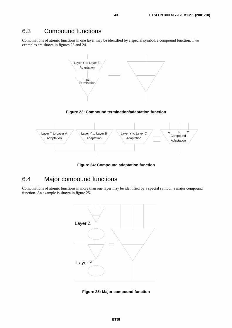
ETSI
ETSI EN 300 417-1-1 V1.2.1 (2001-10)43
6.3 Compound functions Combinations of atomic functions in one layer may be identified by a special symbol, a compound function. Two examples are shown in figures 23 and 24.
TrailTermination
Layer Y to Layer Z
Adaptation
Figure 23: Compound termination/adaptation function
Layer Y to Layer A
Adaptation
Layer Y to Layer B
Adaptation
Layer Y to Layer C
AdaptationCompound
Adaptation
BA C
Figure 24: Compound adaptation function
6.4 Major compound functions Combinations of atomic functions in more than one layer may be identified by a special symbol, a major compound function. An example is shown in figure 25.
Layer Z
Layer Y
Figure 25: Major compound function
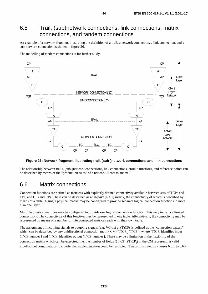
ETSI
ETSI EN 300 417-1-1 V1.2.1 (2001-10)44
6.5 Trail, (sub)network connections, link connections, matrix connections, and tandem connections
An example of a network fragment illustrating the definition of a trail, a network connection, a link connection, and a sub-network connection is shown in figure 26.
The modelling of tandem connections is for further study.
A
TT
TT
A
C
C
A
TT
TT
A
C
C
TRAIL
NETWORK CONNECTION (NC)
TRAIL
NETWORK CONNECTION
SNCLC LC
LINK CONNECTION (LC)TCP
AP
CP
CP
AP
TCP
CPCPCPCP
TCP
AP
CP
TCP
AP
CP
ServerLayer
Network
ServerLayer
ClientLayer
ClientLayer
Network
Figure 26: Network fragment illustrating trail, (sub-)network connections and link connections
The relationship between trails, (sub-)network connections, link connections, atomic functions, and reference points can be described by means of the "production rules" of a network. Refer to annex C.
6.6 Matrix connections Connection functions are defined as matrices with explicitly defined connectivity available between sets of TCPs and CPs, and CPs and CPs. These can be described as an n-port (n ≥ 1) matrix, the connectivity of which is described by means of a table. A single physical matrix may be configured to provide separate logical connection functions in more than one layer.
Multiple physical matrices may be configured to provide one logical connection function. This may introduce limited connectivity. The connectivity of this function may be represented in one table. Alternatively, the connectivity may be represented by means of a number of interconnected matrices each with their own table.
The assignment of incoming signals to outgoing signals (e.g. VC-ns) at (T)CPs is defined as the "connection pattern" which can be described by any unidirectional connection matrix CM ((T)CPi, (T)CPj), where (T)CPi identifies input
(T)CP number i and (T)CPj identifies output (T)CP number j. There may be a limitation in the flexibility of the
connection matrix which can be exercised; i.e. the number of fields ((T)CPi, (T)CPj) in the CM representing valid
input/output combinations in a particular implementation could be restricted. This is illustrated in clauses 6.6.1 to 6.6.4.
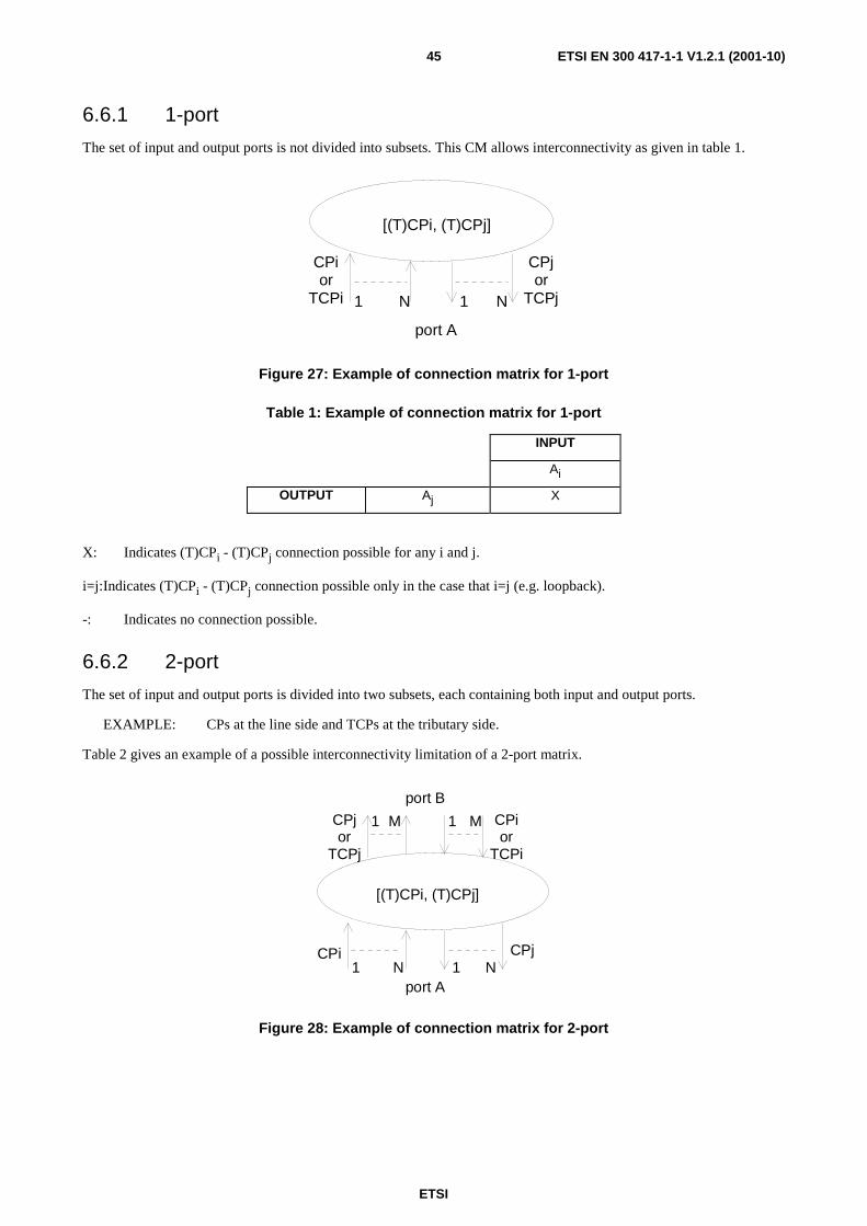
ETSI
ETSI EN 300 417-1-1 V1.2.1 (2001-10)45
6.6.1 1-port
The set of input and output ports is not divided into subsets. This CM allows interconnectivity as given in table 1.
CPior
TCPi
CPjor
TCPj
[(T)CPi, (T)CPj]
port A
1 N 1 N
Figure 27: Example of connection matrix for 1-port
Table 1: Example of connection matrix for 1-port
INPUT
Ai
OUTPUT Aj X
X: Indicates (T)CPi - (T)CPj connection possible for any i and j.
i=j: Indicates (T)CPi - (T)CPj connection possible only in the case that i=j (e.g. loopback).
-: Indicates no connection possible.
6.6.2 2-port
The set of input and output ports is divided into two subsets, each containing both input and output ports.
EXAMPLE: CPs at the line side and TCPs at the tributary side.
Table 2 gives an example of a possible interconnectivity limitation of a 2-port matrix.
CPi
CPior
TCPi
CPjor
TCPj
CPj
[(T)CPi, (T)CPj]
port B
1 M 1 M
port A1 N 1 N
Figure 28: Example of connection matrix for 2-port
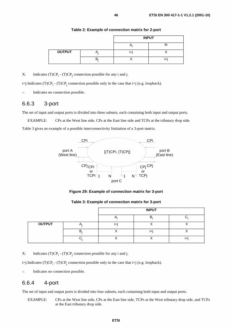
ETSI
ETSI EN 300 417-1-1 V1.2.1 (2001-10)46
Table 2: Example of connection matrix for 2-port
INPUT
Ai Bi
OUTPUT Aj i=j X
Bj X i=j
X: Indicates (T)CPi - (T)CPj connection possible for any i and j.
i=j: Indicates (T)CPi - (T)CPj connection possible only in the case that i=j (e.g. loopback).
-: Indicates no connection possible.
6.6.3 3-port
The set of input and output ports is divided into three subsets, each containing both input and output ports.
EXAMPLE: CPs at the West line side, CPs at the East line side and TCPs at the tributary drop side.
Table 3 gives an example of a possible interconnectivity limitation of a 3-port matrix.
CPi
CPior
TCPi
CPjor
TCPj
CPj
[(T)CPi, (T)CPj] port B(East line)
port C1 N 1 N
port A(West line)
CPi
CPj
Figure 29: Example of connection matrix for 3-port
Table 3: Example of connection matrix for 3-port
INPUT
Ai Bi Ci
OUTPUT Aj i=j X X
Bj X i=j X
Cj X X i=j
X: Indicates (T)CPi - (T)CPj connection possible for any i and j.
i=j: Indicates (T)CPi - (T)CPj connection possible only in the case that i=j (e.g. loopback).
-: Indicates no connection possible.
6.6.4 4-port
The set of input and output ports is divided into four subsets, each containing both input and output ports.
EXAMPLE: CPs at the West line side, CPs at the East line side, TCPs at the West tributary drop side, and TCPs at the East tributary drop side.
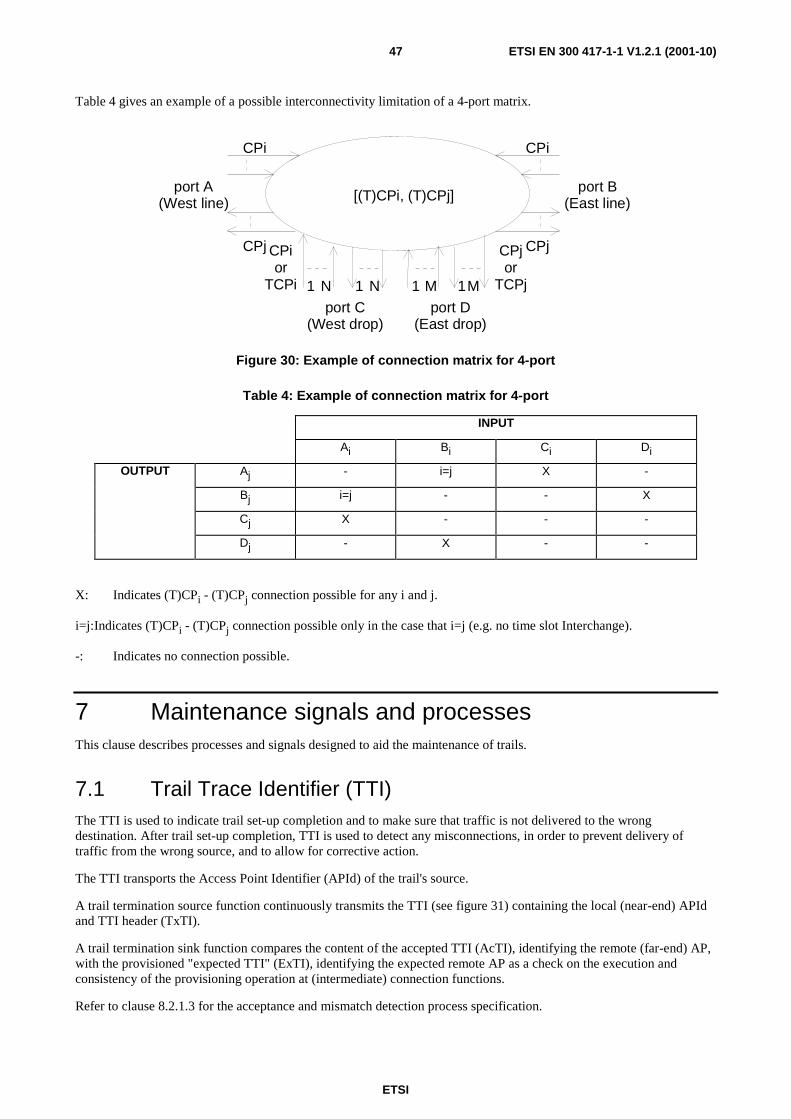
ETSI
ETSI EN 300 417-1-1 V1.2.1 (2001-10)47
Table 4 gives an example of a possible interconnectivity limitation of a 4-port matrix.
CPi
CPior
TCPi
CPjor
TCPj
CPj
[(T)CPi, (T)CPj]port B
(East line)
port C(West drop)
1 N 1M
port A(West line)
CPi
CPj
1 N
port D(East drop)
1 M
Figure 30: Example of connection matrix for 4-port
Table 4: Example of connection matrix for 4-port
INPUT
Ai Bi Ci Di
OUTPUT Aj - i=j X -
Bj i=j - - X
Cj X - - -
Dj - X - -
X: Indicates (T)CPi - (T)CPj connection possible for any i and j.
i=j: Indicates (T)CPi - (T)CPj connection possible only in the case that i=j (e.g. no time slot Interchange).
-: Indicates no connection possible.
7 Maintenance signals and processes This clause describes processes and signals designed to aid the maintenance of trails.
7.1 Trail Trace Identifier (TTI) The TTI is used to indicate trail set-up completion and to make sure that traffic is not delivered to the wrong destination. After trail set-up completion, TTI is used to detect any misconnections, in order to prevent delivery of traffic from the wrong source, and to allow for corrective action.
The TTI transports the Access Point Identifier (APId) of the trail's source.
A trail termination source function continuously transmits the TTI (see figure 31) containing the local (near-end) APId and TTI header (TxTI).
A trail termination sink function compares the content of the accepted TTI (AcTI), identifying the remote (far-end) AP, with the provisioned "expected TTI" (ExTI), identifying the expected remote AP as a check on the execution and consistency of the provisioning operation at (intermediate) connection functions.
Refer to clause 8.2.1.3 for the acceptance and mismatch detection process specification.

ETSI
ETSI EN 300 417-1-1 V1.2.1 (2001-10)48
TT TT
AP
TCP
APId
TT TT
AP
TCP
APId
CP CP CP CP CP CP
C C C C
LC LC LC
MC MCMC MC
TRAIL
TxTIExTIAcTIRxTI
ExTIAcTIRxTI
TxTI
Figure 31: A bi-directional trail and its trace identifier parameters
Definition of TTI
Mode 1
The TTI, shown in table 5, is a 16 byte string containing the 15 byte APId and a 1 byte header. The MSB of the header is a "1", the remaining 7 bits contain the CRC-7 value of the TTI. The MSB of the 15 APId bytes is "0".
The CRC-7 word is the remainder after multiplication by x7 and then division (modulo 2) by the generator polynomial x7 + x3 + 1, of the polynomial representation of the TTI with the CRC bits set to binary zeroes (see note).
NOTE: Contrary to e.g. CRC-4 procedure in 2 Mbit/s signals, the CRC-7 word is static because the date is static (the TTI represents the source address). This means the CRC-7 checksum can be calculated a priori over the TTI.
When representing the contents of the check block as a polynomial, the first bit in the block, i.e. bit 1 of byte 0, should be taken as being the most significant bit. Similarly, C1 is defined to be the most significant bit of the remainder and C7
the least significant bit of the remainder.
The 16 TxTI, 16 ExTI and 16 AcTI bytes are transferred via the Management Point to and from the trail termination function.
Table 5: Trace Identifier contents
TTI byte#
value (bit 1,2,..,8) APId byte #
0 1 C1 C2 C3 C4 C5 C6 C7 --
1 0 X X X X X X X 1 2 0 X X X X X X X 2 : : : :
15 0 X X X X X X X 15
Mode 2
For backward compatibility, to support VCs/STM-Ns not containing TTIs (from old equipment), the "expected TTI" code shall not be provisioned. In such a case, the received TTI is assumed to be a "constantly repeating single byte".
NOTE: With this method, new equipment is capable of detecting a misconnection to other new equipment when expecting the signal from old equipment.

ETSI
ETSI EN 300 417-1-1 V1.2.1 (2001-10)49
7.2 Trail Signal Label (TSL) The TSL supports three applications. It identifies:
1) whether the received signal is (supervisory-)unequipped or equipped (process within the termination and non-intrusive monitor functions);
2) the payload composition/type (process within the adaptation function).
3) whether the received signal contains AIS (process within the non-intrusive monitor function).
Definition of unequipped VC signal:
- an all "0s" signal label;
- an all "0s" trail trace identifier;
- an all "0s" network operator byte;
- a valid VC BIP;
- an unspecified remainder of the VC (i.e. VC payload, other overhead).
NOTE: In future, it may be a requirement to generate an unequipped VC as an all-ZEROs signal in the entire VC.
Definition of supervisory-unequipped VC signal:
- a valid trail trace identifier;
- an all "0s" signal label;
- an all "0s" network operator byte;
- a valid VC BIP;
- a valid RDI and REI;
- an unspecified remainder of the VC (i.e. VC payload, other overhead).
The VC supervisory-unequipped signal is an enhanced unequipped VC and is detected as an unequipped VC.
7.2.1 Unequipped signal application
NOTE: This clause does not apply to supervisory-unequipped signals.
The unequipped signal indicates to downstream transport processing functions that the connection is not bound to, or not connected (via a matrix connection) to a termination source function.
If an unequipped VC signal is received, almost every bit in the VC is unspecified. Consequently, defect reporting of unspecified bits during an unequipped condition should be suppressed (i.e. cTIM, cRDI). Also, far-end PM processing is not possible (RDI and REI are undefined).
One of the possible errors which may occur while the network is being provisioned by the network manager is the unintended release of a matrix connection, resulting in an open connection matrix output (i.e. not connected to a connection matrix input). In this case, the transmitted signal will be the unequipped VC signal (refer to clause 8.2.2.7). The receiving termination function can detect this disconnection by evaluating the signal label byte/bits for code '0' (unequipped). Formally, the reception of a signal label code '0' is not a payload mismatch defect, but rather a "loss of signal" condition (see note 1).
NOTE 1: The unintentionally removed matrix connection and the broken cable/fiber both result in an unplanned disconnection.
Connection functions (figure 32) (see note 2) represent the switch matrices in network elements. A connection function has a number of inputs and a number of outputs (see note 3). The number of inputs may or may not be equal to the number of outputs. All outputs may or may not be connected to inputs.

ETSI
ETSI EN 300 417-1-1 V1.2.1 (2001-10)50
NOTE 2: The connection functions in the figure show three connection points, by which the connection function is connected to adaptation functions in the server layer, and one termination connection point, by which the connection function is connected to a trail termination function in the same layer.
NOTE 3: The connection functions in the figure show three connection points, by which the connection function is connected to adaptation functions in the server layer, and one termination connection point, by which the connection function is connected to a trail termination function in the same layer.
Outputs which are not connected to an input transmit an idle signal: the unequipped VC signal (UNEQ). This suppresses failure notifications from downstream adaptation functions.
TT
"UNEQ"
TT TT
"UNEQ"
TT
C C
Server Layer
Link Connections
Server Layer
TCP
CP
TCPTCPTCP
CPCP
CPCP
CP
CPCP
CP
CPCP
CP
Figure 32: Generation of unequipped VC in connection functions
Not all equipment will have a real connection function (i.e. switch matrix) implemented, and in such cases less than 100 % of the trail termination functions may be installed or operational. If this is intentionally the case, the associated AUs (TUs) should carry unequipped VCs. The connection points in such equipment represent a "virtual" connection function and the outputs of this "virtual" connection function are not connected to inputs.
7.2.2 Supervisory-unequipped signal application
In addition to the unequipped signal application, the supervisory-unequipped allows enhanced supervision of connections which are not part of a trail. The supervisory-unequipped signal is a test signal with undefined payload. Refer to annex H for a description of the application.
Outputs of a connection function which are not connected to an input transmit an idle signal - the unequipped VC signal (UNEQ) - which can be replaced by the supervisory-unequipped signal if the termination supervisory unequipped source (TTs_So) function is present as depicted in figure 33 ("in line" option). The (tandem) link connection is connected to two trail termination supervisory unequipped functions, via Matrix Connections (MCs) in the supervisory-unequipped Connection function (Cs). The trail termination supervisory unequipped source function (TTs_So) supplies a supervisory-unequipped signal. The Trail Termination supervisory unequipped Sink function (TTs_Sk) monitors the signal.
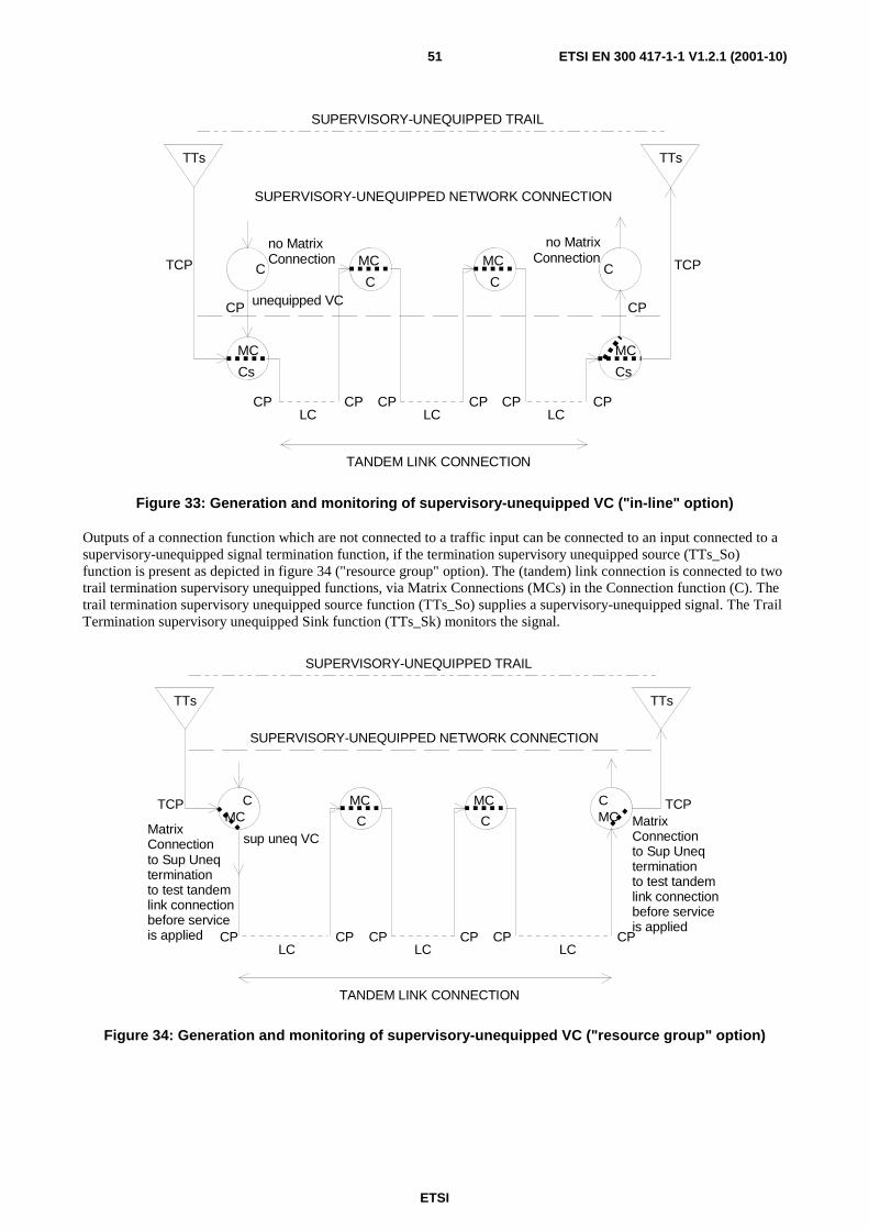
ETSI
ETSI EN 300 417-1-1 V1.2.1 (2001-10)51
TCP TCP
CP CP CP CP CP CP
Cs
C C
Cs
LC LC LC
SUPERVISORY-UNEQUIPPED NETWORK CONNECTION
TTs TTs
TANDEM LINK CONNECTION
CP CP
C C
no MatrixConnection
no MatrixConnection
unequipped VC
SUPERVISORY-UNEQUIPPED TRAIL
MC
MC MC
MC
Figure 33: Generation and monitoring of supervisory-unequipped VC ("in-line" option)
Outputs of a connection function which are not connected to a traffic input can be connected to an input connected to a supervisory-unequipped signal termination function, if the termination supervisory unequipped source (TTs_So) function is present as depicted in figure 34 ("resource group" option). The (tandem) link connection is connected to two trail termination supervisory unequipped functions, via Matrix Connections (MCs) in the Connection function (C). The trail termination supervisory unequipped source function (TTs_So) supplies a supervisory-unequipped signal. The Trail Termination supervisory unequipped Sink function (TTs_Sk) monitors the signal.
TCP TCP
CP CP CP CP CP CP
C C
LC LC LC
SUPERVISORY-UNEQUIPPED NETWORK CONNECTION
TTs TTs
TANDEM LINK CONNECTION
C C
MatrixConnectionto Sup Uneqterminationto test tandemlink connectionbefore service is applied
sup uneq VC
SUPERVISORY-UNEQUIPPED TRAIL
MCMC MC
MC MatrixConnectionto Sup Uneqterminationto test tandemlink connectionbefore service is applied
Figure 34: Generation and monitoring of supervisory-unequipped VC ("resource group" option)

ETSI
ETSI EN 300 417-1-1 V1.2.1 (2001-10)52
7.2.3 Adaptation function selection supervision process
An Adaptation source function transmits the TSL (TxSL) which identifies the local (near-end) selected payload type and hence the adaptation or composition (see note 1), of adaptation function type(s) (see note 2). The TSL code acts as an adaptation source function identification code. The exact coding of the TSL is described in the respective adaptation functions in the other parts of the present document.
NOTE 1: The identification of a composition of adaptation function types by one TSL code is due to the limited number of code values per TSL.
NOTE 2: A particular adaptation function type serves a particular type client layer. An other adaptation function type serves another type client layer.
An adaptation sink function compares the content of the accepted TSL (AcSL) (see note 3), identifying the remote (far-end) adaptation function, with the "Expected TSL" (ExSL), identifying the local adaptation function as a check on consistency between the provisioning operation at each end of the trail.
NOTE 3: Refer to clause 8.2.1.2 for the definition of AcSL.
For backward compatibility (to interwork with old equipment not containing equipped-specific TSLs), every equipped-specific "expected TSL" code is matched by the "equipped - non specific" TSL code (code "1").
TT TT
AP
TCP
TT TT
AP
TCP
CP CP CP CP
C C C
LC LC
MCMC MC
TRAIL
TxSL
ExSL=TxSLAcSLRxSL
ExSL=TxSLAcSLRxSL
TxSL
A #2 A #1 A #2A #1 A #2 A #1 A #2A #1
A #1 : SL=PA #2 : SL=Q
Figure 35: A bi-directional trail and its Signal Label parameters
Figure 35 shows an example of a trail which is terminated in network elements which include two adaptation function types (type #1 and #2). Both network elements have to be provisioned to activate the same adaptation function type. Mis-provisioning, for example type #1 at trail source and type #2 at trail sink, can cause uncontrolled behaviour of the signal output by the adaptation sink function.
7.2.4 Connection monitoring application
The availability of tandem link connections (see note) which do not carry live traffic/services (i.e. they are not part of a network connection) is monitored by means of adaptation characteristics: LOP and AIS.
NOTE: A tandem link connection is a series of link connections and matrix connections which start and end with a LC. e.g.: LC - MC - LC - MC - LC. The minimum tandem link connection is a single LC.
For the case that a tandem link connection is set-up but not put into service, additional monitoring might be requested. This "pre-service monitoring" can be:
a) through the application of the supervisory-unequipped signal as shown in figure 33 and annex H;
b) through the introduction of a test trail, which is for further study.
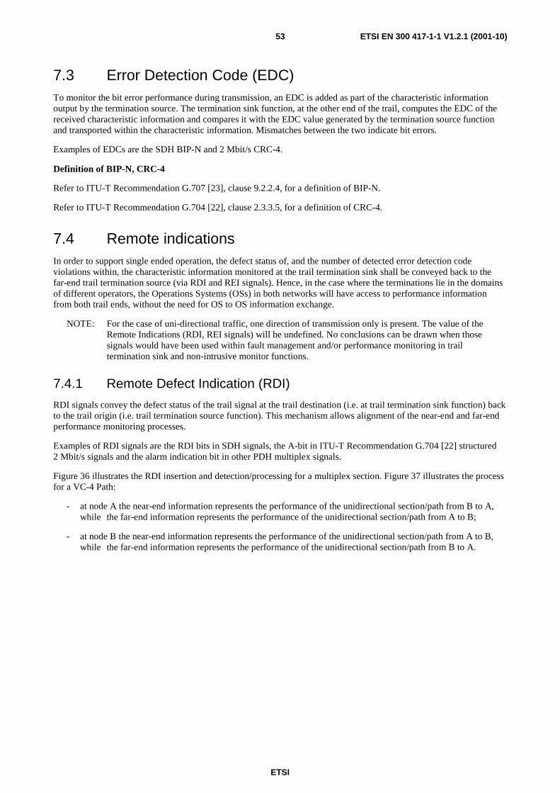
ETSI
ETSI EN 300 417-1-1 V1.2.1 (2001-10)53
7.3 Error Detection Code (EDC) To monitor the bit error performance during transmission, an EDC is added as part of the characteristic information output by the termination source. The termination sink function, at the other end of the trail, computes the EDC of the received characteristic information and compares it with the EDC value generated by the termination source function and transported within the characteristic information. Mismatches between the two indicate bit errors.
Examples of EDCs are the SDH BIP-N and 2 Mbit/s CRC-4.
Definition of BIP-N, CRC-4
Refer to ITU-T Recommendation G.707 [23], clause 9.2.2.4, for a definition of BIP-N.
Refer to ITU-T Recommendation G.704 [22], clause 2.3.3.5, for a definition of CRC-4.
7.4 Remote indications In order to support single ended operation, the defect status of, and the number of detected error detection code violations within, the characteristic information monitored at the trail termination sink shall be conveyed back to the far-end trail termination source (via RDI and REI signals). Hence, in the case where the terminations lie in the domains of different operators, the Operations Systems (OSs) in both networks will have access to performance information from both trail ends, without the need for OS to OS information exchange.
NOTE: For the case of uni-directional traffic, one direction of transmission only is present. The value of the Remote Indications (RDI, REI signals) will be undefined. No conclusions can be drawn when those signals would have been used within fault management and/or performance monitoring in trail termination sink and non-intrusive monitor functions.
7.4.1 Remote Defect Indication (RDI)
RDI signals convey the defect status of the trail signal at the trail destination (i.e. at trail termination sink function) back to the trail origin (i.e. trail termination source function). This mechanism allows alignment of the near-end and far-end performance monitoring processes.
Examples of RDI signals are the RDI bits in SDH signals, the A-bit in ITU-T Recommendation G.704 [22] structured 2 Mbit/s signals and the alarm indication bit in other PDH multiplex signals.
Figure 36 illustrates the RDI insertion and detection/processing for a multiplex section. Figure 37 illustrates the process for a VC-4 Path:
- at node A the near-end information represents the performance of the unidirectional section/path from B to A, while the far-end information represents the performance of the unidirectional section/path from A to B;
- at node B the near-end information represents the performance of the unidirectional section/path from A to B, while the far-end information represents the performance of the unidirectional section/path from B to A.
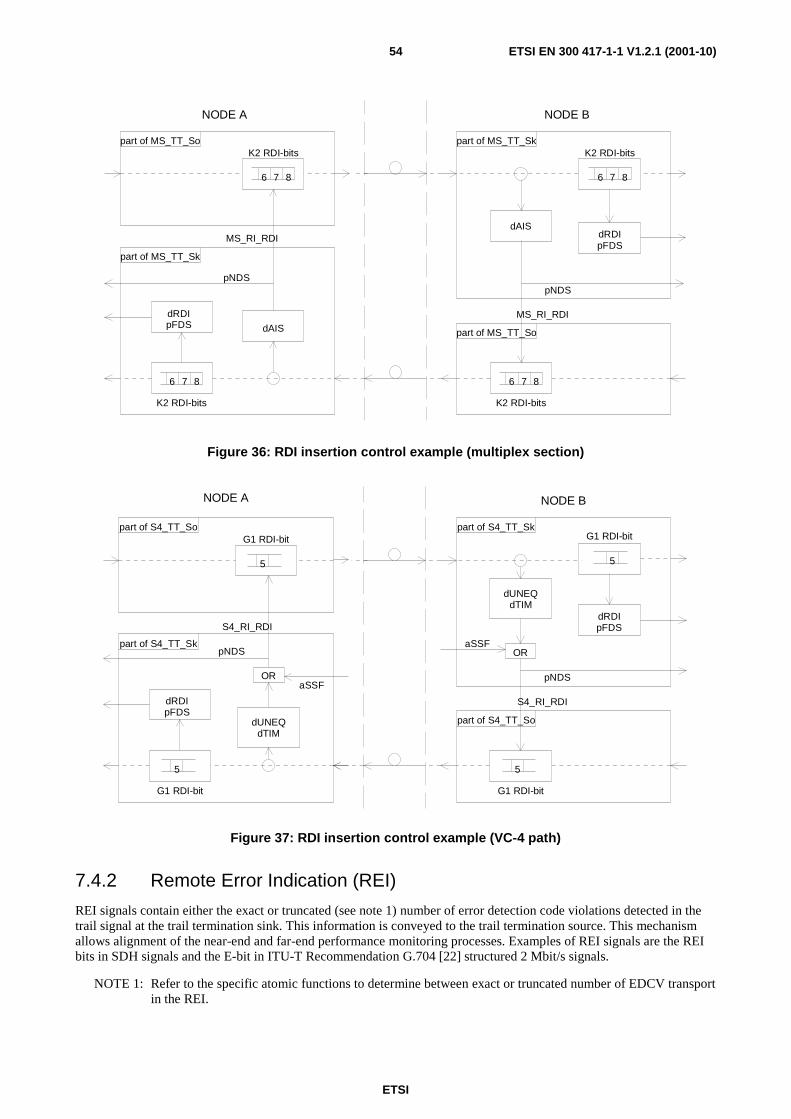
ETSI
ETSI EN 300 417-1-1 V1.2.1 (2001-10)54
dAIS
6 7 8
K2 RDI-bits
6 7 8
K2 RDI-bits
pNDS
part of MS_TT_Sk
NODE BNODE A
part of MS_TT_So
part of MS_TT_So
part of MS_TT_Sk
dRDIpFDS
MS_RI_RDI
6 7 8
K2 RDI-bits
dRDIpFDS
dAIS
pNDS
MS_RI_RDI
6 7 8
K2 RDI-bits
Figure 36: RDI insertion control example (multiplex section)
dUNEQdTIM
OR
G1 RDI-bit
5
G1 RDI-bit
pNDS
part of S4_TT_Sk
NODE BNODE A
part of S4_TT_So
part of S4_TT_So
part of S4_TT_Sk
dRDIpFDS
S4_RI_RDI
aSSF
5
5
G1 RDI-bit
dRDIpFDS
dUNEQdTIM
OR
pNDS
S4_RI_RDI
aSSF
G1 RDI-bit
5
Figure 37: RDI insertion control example (VC-4 path)
7.4.2 Remote Error Indication (REI)
REI signals contain either the exact or truncated (see note 1) number of error detection code violations detected in the trail signal at the trail termination sink. This information is conveyed to the trail termination source. This mechanism allows alignment of the near-end and far-end performance monitoring processes. Examples of REI signals are the REI bits in SDH signals and the E-bit in ITU-T Recommendation G.704 [22] structured 2 Mbit/s signals.
NOTE 1: Refer to the specific atomic functions to determine between exact or truncated number of EDCV transport in the REI.

ETSI
ETSI EN 300 417-1-1 V1.2.1 (2001-10)55
NOTE 2: REI is not suppressed in all cases RDI is active. If an RDI is active, REI is not specified. Such will not introduce operational problems. The performance monitoring process ignores the error count communicated via the REI signal for the second containing an active RDI.
Figure 38 illustrates the REI insertion and extraction/processing for a VC-4 bi-directional path:
- at node A the near-end information represents the performance of the unidirectional path from B to A, while the far-end information represents the performance of the unidirectional path from A to B;
- at node B the near-end information represents the performance of the unidirectional path from A to B, while the far-end information represents the performance of the unidirectional path from B to A.
G1 REI-bits
part of S4_TT_Sk
NODE BNODE A
part of S4_TT_So
S4_RI_REI
BIP-8calc.
BIP-8read
BIP-8 violations
pNEBCdDEG
B3 BIP-8 bits
1 2 8
1 2 43
pFEBC
G1 REI-bits
1 2 43
B3 BIP-8 bits
1 2
BIP-8calc.
8
G1 REI-bits
part of S4_TT_Sk
part of S4_TT_So
S4-RI_REI
BIP-8calc.
BIP-8read
BIP-8 violations
pNEBCdDEG
B3 BIP-8 bits
1 2 8
1 2 43
pFEBC
G1 REI-bits
1 2 43
B3 BIP-8 bits
1 2
BIP-8calc.
8
Figure 38: REI insertion control example (VC-4 path)
7.5 Alarm Indication Signal (AIS) The AlS is an all-ONEs characteristic or adapted information signal. It is generated to replace the normal traffic signal when it contains a defect condition in order to prevent consequential downstream failures being declared and alarms being raised.
All-ONEs (AIS) insertion in the sink direction is controlled as follows: every atomic function inserts all-ONEs on locally detected defects only, with one of the defects being incoming AIS from upstream atomic functions.
Figure 39 illustrates this process. Due to a LOF defect (STM1dLOF) the OS1/RS1_A_Sk inserts the all-ONEs signal. This signal is propagated through the RS1 layer. The MS1_TT_Sk detects this all-ONEs signal by monitoring bits 6 - 8 of K2. The MS1/S4_A_Sk detects the all-ONEs signal by monitoring the pointer bytes H1, H2. As a consequence both functions insert all-ONEs at their outputs (i.e. they "refresh" the all-ONEs signal). This behaviour is continued in the other client layers.
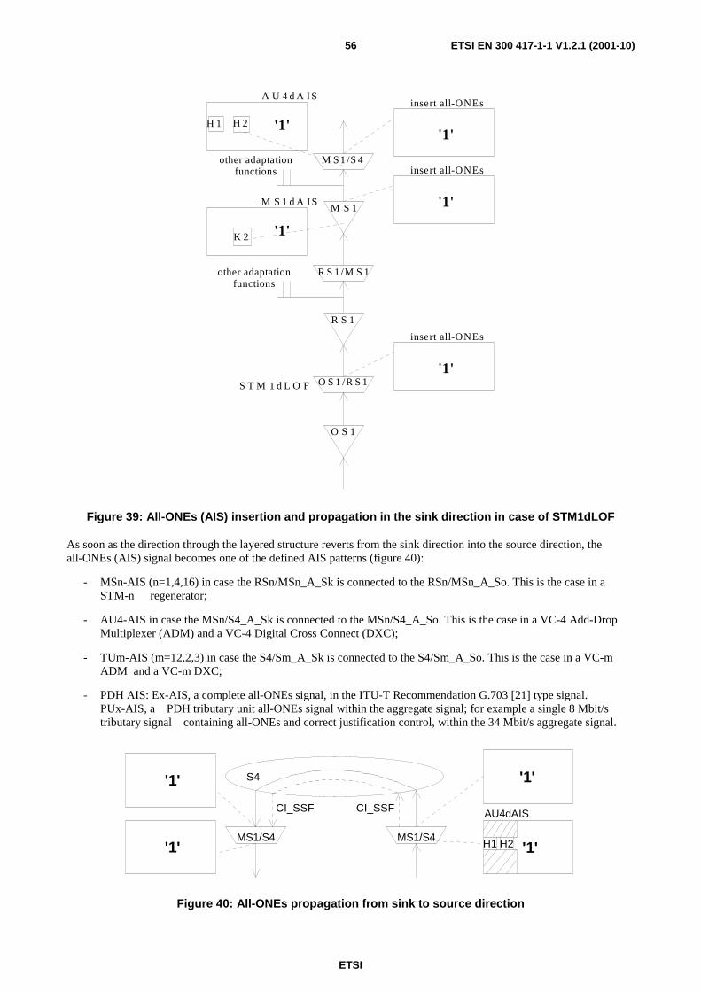
ETSI
ETSI EN 300 417-1-1 V1.2.1 (2001-10)56
M S 1 /S 4
M S 1
H 1 H 2 '1'
K 2 '1'
R S 1 /M S 1
R S 1
O S 1 /R S 1
O S 1
'1'S T M 1 d L O F
M S 1 d A I S
A U 4 d A I S
'1'
insert all-ONEs
insert all-ONEs
'1'
insert all-ONEs
other adaptationfunctions
other adaptationfunctions
Figure 39: All-ONEs (AIS) insertion and propagation in the sink direction in case of STM1dLOF
As soon as the direction through the layered structure reverts from the sink direction into the source direction, the all-ONEs (AIS) signal becomes one of the defined AIS patterns (figure 40):
- MSn-AIS (n=1,4,16) in case the RSn/MSn_A_Sk is connected to the RSn/MSn_A_So. This is the case in a STM-n regenerator;
- AU4-AIS in case the MSn/S4_A_Sk is connected to the MSn/S4_A_So. This is the case in a VC-4 Add-Drop Multiplexer (ADM) and a VC-4 Digital Cross Connect (DXC);
- TUm-AIS (m=12,2,3) in case the S4/Sm_A_Sk is connected to the S4/Sm_A_So. This is the case in a VC-m ADM and a VC-m DXC;
- PDH AIS: Ex-AIS, a complete all-ONEs signal, in the ITU-T Recommendation G.703 [21] type signal. PUx-AIS, a PDH tributary unit all-ONEs signal within the aggregate signal; for example a single 8 Mbit/s tributary signal containing all-ONEs and correct justification control, within the 34 Mbit/s aggregate signal.
MS1/S4 MS1/S4'1' '1'
AU4dAIS
H1 H2
'1'
CI_SSF CI_SSF
'1' S4
Figure 40: All-ONEs propagation from sink to source direction

ETSI
ETSI EN 300 417-1-1 V1.2.1 (2001-10)57
The all-ONEs and CI_SSF signal applied at the input of the MS1/S4_A_So (figure 41) results in the generation of an all-ONEs signal at the output. The MS1_TT_So and the other MS1 adaptation functions (e.g. MS1/OW_A_So) add the MSOH to the all-ONEs signal. The RS1_TT_So and the RS1 adaptation functions add the RSOH. The result is the so called AU-4 AIS signal. This signal is transmitted to the far-end. The STM-1 signal passes through the functions up to the MS1_TT_Sk. Then the MS1/S4_A_Sk function detects AU-4 AIS. It declares the AU4dAIS defect and inserts all-ONEs at its output.
MS1/S4
MS1
RS1/MS1
RS1 RS1
MS1
RS1/MS1
MS1/S4
RSOH
MSOH
'1'
MSOH
'1'
'1'
RSOH
MSOH
'1'
MSOH
'1'
'1'
AU4dAIS
H1 H2
'1'
CI_SSF CI_SSF
'1'
other adaptationfunctions
other adaptationfunctions
Figure 41: All-ONEs (AIS) generation in the source and detection in the sink direction
Similarly, the reception of an all-ONEs signal at the S4/S12_A_So results in the generation of an all-ONEs (TU) signal at the output of the function. This signal is multiplexed with the other TUs, after which the VC-4 overhead, AU-4 pointer, MSOH and RSOH are added. The result is a STM-N signal with a TU carrying TU-AIS.
7.6 Non-intrusive monitoring of characteristic information at connection points
Characteristic Information can be monitored at connection points by means of a non-intrusive monitor (NIM) function. The applications are:
1) Fault localization; in this case the NIM is connected to the passing through VC when the path termination detected a problem which can not be located immediately to a failed resource in the network. Examples are detection of UNEQ, TIM, DEG, or TR (threshold reports from PM). Used are the near end defect detectors and near-end PM information. Note - The NIM is temporarily connected only.
2) SNC/N protection; the NIM monitors for near-end defects and generates the SF (= CI_SSF or dAIS or dUNEQ or dTIM) and SD (= dDEG) conditions. Note that the "advanced NIM" replaces the term "dUNEQ" in the SF by "(dUNEQ and (AcTI=all"0"s))" to cope with the supervisory-unequipped VC signal which has the signal label set to 0.
3) Segment monitoring when TCM functionality is not present; for each direction a NIM is connected at ingress and egress of the network domain. As such, 2x 2 NIMs are present. The near-end information in one direction of an ingress and an egress NIM are compared at OS level to derive the performance (fault and PM) of the segment. Note - if the expected trace identifier is unknown (for the case of multiple sources of the VC passing the connection) the TIM defect detection will be disabled. Reading of the received trace identifier will be possible only.
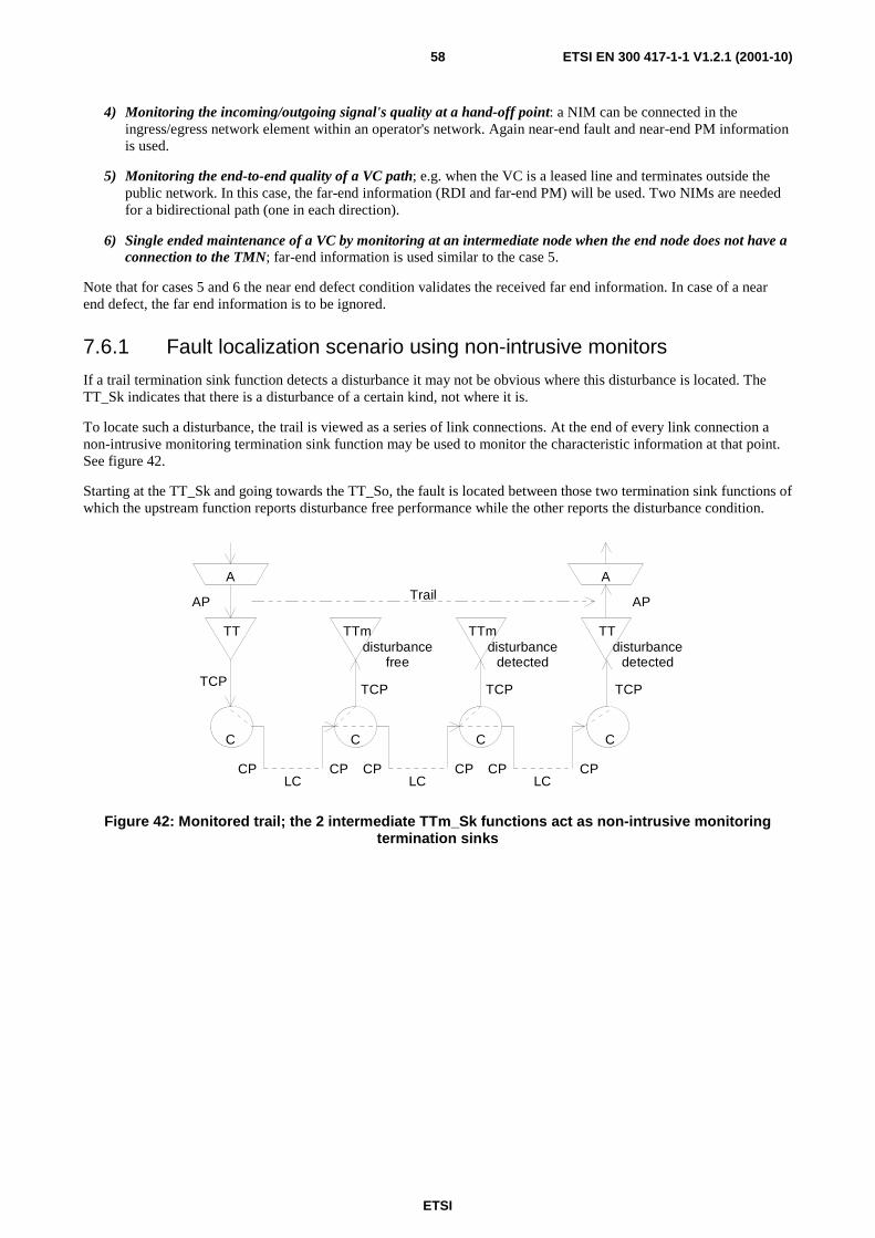
ETSI
ETSI EN 300 417-1-1 V1.2.1 (2001-10)58
4) Monitoring the incoming/outgoing signal's quality at a hand-off point: a NIM can be connected in the ingress/egress network element within an operator's network. Again near-end fault and near-end PM information is used.
5) Monitoring the end-to-end quality of a VC path; e.g. when the VC is a leased line and terminates outside the public network. In this case, the far-end information (RDI and far-end PM) will be used. Two NIMs are needed for a bidirectional path (one in each direction).
6) Single ended maintenance of a VC by monitoring at an intermediate node when the end node does not have a connection to the TMN; far-end information is used similar to the case 5.
Note that for cases 5 and 6 the near end defect condition validates the received far end information. In case of a near end defect, the far end information is to be ignored.
7.6.1 Fault localization scenario using non-intrusive monitors
If a trail termination sink function detects a disturbance it may not be obvious where this disturbance is located. The TT_Sk indicates that there is a disturbance of a certain kind, not where it is.
To locate such a disturbance, the trail is viewed as a series of link connections. At the end of every link connection a non-intrusive monitoring termination sink function may be used to monitor the characteristic information at that point. See figure 42.
Starting at the TT_Sk and going towards the TT_So, the fault is located between those two termination sink functions of which the upstream function reports disturbance free performance while the other reports the disturbance condition.
AP
TCP
AP
TCP
CP CP CP CP CP CP
C C C C
LC LC LC
TT TT
A A
TCP
TTm
TCP
TTmdisturbance
detecteddisturbance
detecteddisturbance
free
Trail
Figure 42: Monitored trail; the 2 intermediate TTm_Sk functions act as non-intrusive monitoring termination sinks
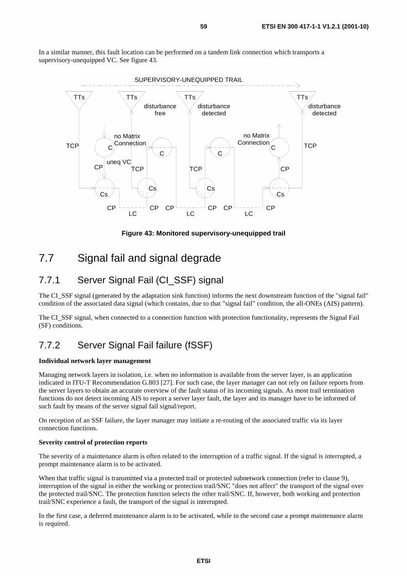
ETSI
ETSI EN 300 417-1-1 V1.2.1 (2001-10)59
In a similar manner, this fault location can be performed on a tandem link connection which transports a supervisory-unequipped VC. See figure 43.
TCP TCP
CP CP CP CP CP CP
Cs
C C
Cs
LC LC LC
TTs TTs
CP CP
C C
no MatrixConnection
no MatrixConnection
uneq VC
SUPERVISORY-UNEQUIPPED TRAIL
TCP
TTs
Cs Cs
TCP
TTsdisturbance
freedisturbance
detecteddisturbance
detected
Figure 43: Monitored supervisory-unequipped trail
7.7 Signal fail and signal degrade
7.7.1 Server Signal Fail (CI_SSF) signal
The CI_SSF signal (generated by the adaptation sink function) informs the next downstream function of the "signal fail" condition of the associated data signal (which contains, due to that "signal fail" condition, the all-ONEs (AIS) pattern).
The CI_SSF signal, when connected to a connection function with protection functionality, represents the Signal Fail (SF) conditions.
7.7.2 Server Signal Fail failure (fSSF)
Individual network layer management
Managing network layers in isolation, i.e. when no information is available from the server layer, is an application indicated in ITU-T Recommendation G.803 [27]. For such case, the layer manager can not rely on failure reports from the server layers to obtain an accurate overview of the fault status of its incoming signals. As most trail termination functions do not detect incoming AIS to report a server layer fault, the layer and its manager have to be informed of such fault by means of the server signal fail signal/report.
On reception of an SSF failure, the layer manager may initiate a re-routing of the associated traffic via its layer connection functions.
Severity control of protection reports
The severity of a maintenance alarm is often related to the interruption of a traffic signal. If the signal is interrupted, a prompt maintenance alarm is to be activated.
When that traffic signal is transmitted via a protected trail or protected subnetwork connection (refer to clause 9), interruption of the signal in either the working or protection trail/SNC "does not affect" the transport of the signal over the protected trail/SNC. The protection function selects the other trail/SNC. If, however, both working and protection trail/SNC experience a fault, the transport of the signal is interrupted.
In the first case, a deferred maintenance alarm is to be activated, while in the second case a prompt maintenance alarm is required.

ETSI
ETSI EN 300 417-1-1 V1.2.1 (2001-10)60
The (protection) trail termination function immediately following the (protection) connection function reports the fault status of the protected signal. If the signal output by the (protection) connection function contains all-ONEs (AIS), the protection failed and a prompt maintenance alarm is typically activated. The protection may have failed due to a double fault condition, or a single fault condition and an external protection switch request (refer to clause 9.2.4) forcing the protection switch to select the failed trail/SNC.
7.7.3 Server Signal Degrade (aSSD) signal
The aSSD signal informs the next downstream function of the "signal degrade" condition of the associated data signal.
The aSSD signal is defined only in adaptation sink function in protection sub-layers. The signal relays the aTSD signal generated by the trail termination sink function towards the protection connection function in the protection sublayer. Refer to clause 9.3.
7.7.4 Trail Signal Fail (AI_TSF) signal
The AI_TSF signal (generated by a trail termination sink function) informs the next downstream function(s) of the "signal fail" condition of the associated data signal (which contains, due to that "signal fail" condition, the all-ONEs (AIS) pattern).
The AI_TSF signal, when connected to a connection function with protection functionality, represents a Signal Fail (SF) conditions.
7.7.5 Trail Signal Degrade (aTSD) signal
The aTSD signal (generated by a trail termination sink function) informs the next function(s) of the "signal degrade" condition of the associated data signal.
The aTSD signal is only connected to a connection function with protection functionality, and represents the Signal Degrade (SD) conditions.
8 Supervision process
8.1 Introduction The supervision process philosophy is based on the concepts underlying the functional model of ITU-T Recommendation G.803 [27] and the information model of ETS 300 304 [5] which distinguishes between Transmission and Equipment supervision processing.
Transmission and equipment supervision processes are concerned with the management of the transmission resources in the network and is only interested in the functionality which is being provided by a Network Element (NE). It requires a functional representation of an NE that is implementation independent. Any equipment faults are represented by the unavailability of the affected functions because the transmission management has no knowledge of the equipment as such. Most functions monitor the signals they are processing for certain characteristics and provide performance information or alarm conditions based on these characteristics. Therefore, transmission supervision processing provides information on the external interface signals that are processed by an NE.
Equipment supervision processing is concerned with the fault localization and repair of the equipment itself. Its purpose is to answer the classic questions: "who to send where to repair what?" It does not require a knowledge of the transmission network, other than that the equipment faults may have been categorized to indicate the urgency (e.g. prompt, deferred, mei (maintenance event information)) of the fault.
NOTE: Refer to ITU-T Recommendation M.20 [37].
The basic functions of the supervision process and their inter-relationships are depicted in figure 44. Figure 45 illustrates three major process groups. Supervision terms and variables used throughout the present document are defined in clauses 3.2 and 3.3.

ETSI
ETSI EN 300 417-1-1 V1.2.1 (2001-10)61
The supervision process describes the way in which the actual occurrence of a disturbance or fault is analysed with the purpose of providing an appropriate indication of performance and/or detected fault condition to maintenance personnel. The following terms are used to describe the supervision process: anomaly, defect, consequent action, fault cause, failure and alarm.
f1
f1f1f1f1
Near-endanomalies
Far-endanomaly
(RDI)
Far-endAnomalies
(REI)
Far-enddefectdRDI
f22
f21
Near-enddefectsdZZZ
f3
f2
aAIS
aRDI
aTSF
ConsequentactionsaZZZ
aSSF
report options(ZZZ_Reported, MON/NMON)enable/disable
f4
f5
f6
f7
f8
Unitalarms
Network elementalarms
Stationalarms
Immediate TMNfailure reports
Fault causecZZZ
FailurefZZZ
EDC violations
aTSFf12
f11
EDC violations
f25
f24
f26
f23
pFDS
pFEBC
F_UATcmd
F_SES
F_ES
F_BBE
f15
f14
f16
f13
pNDS
pNEBC
N_UATcmd
N_SES
N_ES
N_BBE
15 minute24 hour
bins
&
Thresholdcrossing
notifications(TCN)
f31
f32
TMN performancemanagement
reports
f2aREI
aTSD
aSSF
Figure 44: Fault management and performance monitoring decomposition
The supervision process is decomposed into three major sub-processes; atomic function fault management and performance monitoring, EMF fault management, and EMF performance monitoring (figure 45). These sub-processes are described in clauses 8.2, 8.3 and 8.4.

ETSI
ETSI EN 300 417-1-1 V1.2.1 (2001-10)62
Atomic FunctionFault & PerformanceMonitoring process
Equipment Management FunctionFault Management
process
Equipment Management FunctionPerformance Monitoring
process
pZZZ
cZZZ
Figure 45: Decomposition of supervision process
8.2 Atomic function fault management Figure 46 shows the main supervision process related (sub)processes within trail termination and adaptation functions. These processes are referred to as "filters" and are introduced in this clause.
Table 5.1
Filter Function f1 integration of anomalies into defects f2 consequent action control f3 correlation of defects; result is fault cause (correlated defect) f11 Near-end errored block counting f12 Near-end defect second determination process f21 Far-end errored block counting f22 Far-end defect second determination process
Filters f1, f2, and f3 are components of the fault management process located within the atomic functions. Filters f11, f12, f21, and f22 are components of the performance monitoring process located within the atomic function. The output signals cZZZ (e.g. cTIM) are the input signals for the EMF fault management process (clause 8.3), while the output signals pZZZ (e.g. pN_EBC) are the input signals for the EMF performance monitoring process (see clause 8.4).
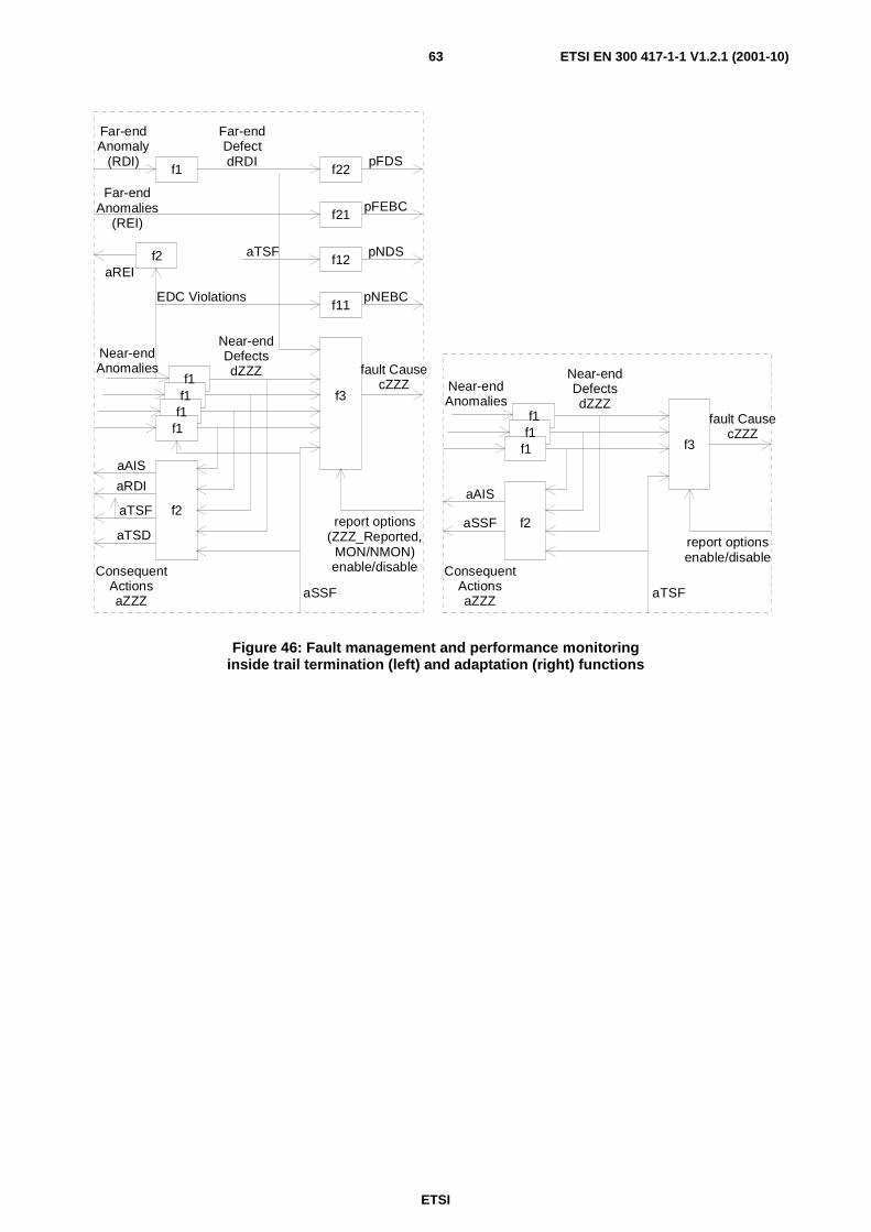
ETSI
ETSI EN 300 417-1-1 V1.2.1 (2001-10)63
f1f1f1
Near-endAnomalies
Near-endDefectsdZZZ
f3
fault CausecZZZ
f2
aAIS
aTSF
ConsequentActionsaZZZ
aSSF
report optionsenable/disable
f1
f1f1f1f1
Near-endAnomalies
Far-endAnomaly
(RDI)
Far-endAnomalies
(REI)
EDC Violations
aTSF
Far-endDefectdRDI pFDS
pFEBC
pNDS
pNEBC
f22
f21
f12
f11
Near-endDefectsdZZZ
f3
fault CausecZZZ
f2
aAIS
aRDI
aTSF
ConsequentActionsaZZZ
aSSF
report options(ZZZ_Reported,
MON/NMON)enable/disable
aREIf2
aTSD
Figure 46: Fault management and performance monitoring inside trail termination (left) and adaptation (right) functions
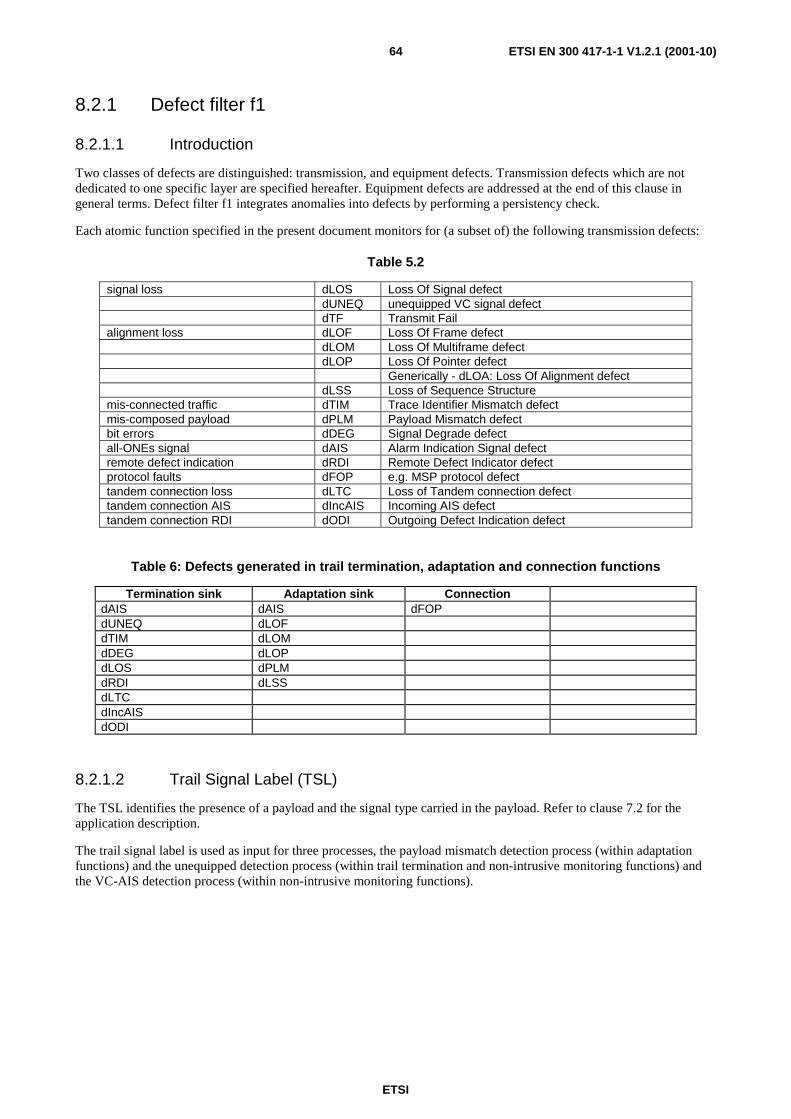
ETSI
ETSI EN 300 417-1-1 V1.2.1 (2001-10)64
8.2.1 Defect filter f1
8.2.1.1 Introduction
Two classes of defects are distinguished: transmission, and equipment defects. Transmission defects which are not dedicated to one specific layer are specified hereafter. Equipment defects are addressed at the end of this clause in general terms. Defect filter f1 integrates anomalies into defects by performing a persistency check.
Each atomic function specified in the present document monitors for (a subset of) the following transmission defects:
Table 5.2
signal loss dLOS Loss Of Signal defect dUNEQ unequipped VC signal defect dTF Transmit Fail alignment loss dLOF Loss Of Frame defect dLOM Loss Of Multiframe defect dLOP Loss Of Pointer defect Generically - dLOA: Loss Of Alignment defect dLSS Loss of Sequence Structure mis-connected traffic dTIM Trace Identifier Mismatch defect mis-composed payload dPLM Payload Mismatch defect bit errors dDEG Signal Degrade defect all-ONEs signal dAIS Alarm Indication Signal defect remote defect indication dRDI Remote Defect Indicator defect protocol faults dFOP e.g. MSP protocol defect tandem connection loss dLTC Loss of Tandem connection defect tandem connection AIS dIncAIS Incoming AIS defect tandem connection RDI dODI Outgoing Defect Indication defect
Table 6: Defects generated in trail termination, adaptation and connection functions
Termination sink Adaptation sink Connection dAIS dAIS dFOP dUNEQ dLOF dTIM dLOM dDEG dLOP dLOS dPLM dRDI dLSS dLTC dIncAIS dODI
8.2.1.2 Trail Signal Label (TSL)
The TSL identifies the presence of a payload and the signal type carried in the payload. Refer to clause 7.2 for the application description.
The trail signal label is used as input for three processes, the payload mismatch detection process (within adaptation functions) and the unequipped detection process (within trail termination and non-intrusive monitoring functions) and the VC-AIS detection process (within non-intrusive monitoring functions).

ETSI
ETSI EN 300 417-1-1 V1.2.1 (2001-10)65
received-TSL(RxSL)
aTSF
accepted-TSL(AcSL)
expected-TSL(ExSL)
dPLMPayload
Mismatch
received-TSL(RxSL)
dUNEQUnequipped VC
dAISall-ONEs VC
received-TSL(RxSL)
Figure 47: Generic trail signal label acceptance, payload mismatch and unequipped detection process
Expected trail signal label
The "expected TSL" shall be derived from the adaptation function type.
Received trail signal label acceptance
The value of the signal label passed to the management system should be an accepted value rather than the received value.
In case of adaptation functions, a new signal label code value shall be accepted if the signal label carries the same code value in m consecutive (multi)frames, with 3 ≤ m ≤ 10.
In the case of termination functions, a new signal label code value shall be accepted if the signal label carries the same code value in five consecutive (multi)frames.
Payload Mismatch (PLM) defect
The Payload Mismatch defect (dPLM) shall be detected if the "accepted TSL" code does not match the "expected TSL" code. If the "accepted TSL" code is "equipped non-specific" the mismatch is not detected. dPLM shall be cleared if the "accepted TSL" code matches the "expected TSL" code, or if the "accepted TSL" code is "equipped non-specific".
The dPLM shall be detected within a maximum period of 100 ms in the absence of bit errors.
The dPLM shall be cleared within a maximum period of 100 ms in the absence of bit errors.
The defect detection process and its operation during the presence of bit errors is for further study.
The defect shall be suppressed during the receipt of AI_TSF.
Unequipped (dUNEQ) defect
The Unequipped defect (dUNEQ) shall be detected if the "accepted TSL" is the unequipped indication (TSL code = 0).
Removal of unequipped defect is detected if the "accepted TSL" contains a non "unequipped" signal label
(TSL code ≥ 1).
The dUNEQ shall be detected within a maximum period of 100 ms in the absence of bit errors.
The dUNEQ shall be cleared within a maximum period of 100 ms in the absence of bit errors.
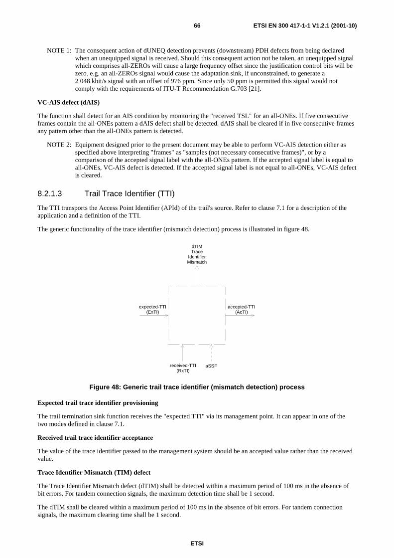
ETSI
ETSI EN 300 417-1-1 V1.2.1 (2001-10)66
NOTE 1: The consequent action of dUNEQ detection prevents (downstream) PDH defects from being declared when an unequipped signal is received. Should this consequent action not be taken, an unequipped signal which comprises all-ZEROs will cause a large frequency offset since the justification control bits will be zero. e.g. an all-ZEROs signal would cause the adaptation sink, if unconstrained, to generate a 2 048 kbit/s signal with an offset of 976 ppm. Since only 50 ppm is permitted this signal would not comply with the requirements of ITU-T Recommendation G.703 [21].
VC-AIS defect (dAIS)
The function shall detect for an AIS condition by monitoring the "received TSL" for an all-ONEs. If five consecutive frames contain the all-ONEs pattern a dAIS defect shall be detected. dAIS shall be cleared if in five consecutive frames any pattern other than the all-ONEs pattern is detected.
NOTE 2: Equipment designed prior to the present document may be able to perform VC-AIS detection either as specified above interpreting "frames" as "samples (not necessary consecutive frames)", or by a comparison of the accepted signal label with the all-ONEs pattern. If the accepted signal label is equal to all-ONEs, VC-AIS defect is detected. If the accepted signal label is not equal to all-ONEs, VC-AIS defect is cleared.
8.2.1.3 Trail Trace Identifier (TTI)
The TTI transports the Access Point Identifier (APId) of the trail's source. Refer to clause 7.1 for a description of the application and a definition of the TTI.
The generic functionality of the trace identifier (mismatch detection) process is illustrated in figure 48.
received-TTI(RxTI)
aSSF
accepted-TTI(AcTI)
expected-TTI(ExTI)
dTIMTrace
IdentifierMismatch
Figure 48: Generic trail trace identifier (mismatch detection) process
Expected trail trace identifier provisioning
The trail termination sink function receives the "expected TTI" via its management point. It can appear in one of the two modes defined in clause 7.1.
Received trail trace identifier acceptance
The value of the trace identifier passed to the management system should be an accepted value rather than the received value.
Trace Identifier Mismatch (TIM) defect
The Trace Identifier Mismatch defect (dTIM) shall be detected within a maximum period of 100 ms in the absence of bit errors. For tandem connection signals, the maximum detection time shall be 1 second.
The dTIM shall be cleared within a maximum period of 100 ms in the absence of bit errors. For tandem connection signals, the maximum clearing time shall be 1 second.

ETSI
ETSI EN 300 417-1-1 V1.2.1 (2001-10)67
The defect shall be suppressed during the receipt of CI_SSF.
When interworking with old equipment refer to clause 7.1.
It shall be possible to disable the trace identifier mismatch defect detection (TIMdis).
NOTE: Trace identifier mismatch defect detection should be disabled to perform APId numbering plan modifications without traffic interruption, to perform non-intrusive monitoring when the APId within the trace identifier is unknown (e.g. within a tandem connection), to support some (protection) applications in which a multipoint to point trail is/can be present.
8.2.1.4 Error Detection Code (EDC) violation and Degraded (DEG)
Bit errors in a signal are detectable by checking the signal's associated EDC for violations. Examples of EDCs are the SDH BIP-N and 2 Mbit/s CRC-4.
EDC Violation detection
The computed EDC shall be compared with the received EDC value in the following frame. If both values differ an errored block (nN_B, nON_B) shall be detected.
As the detection of AIS results in the declaration of a Severely Errored Second (SES), the Error Detection Code Violation (EDCV) process shall assume "zero" EDCVs in the incoming all-ONEs (AIS) signal during an incoming Server Signal Fail (CI_SSF) condition or detection of dAIS (see note).
NOTE: When the server layer does not activate CI_SSF on reception of AIS in the client signal, the termination sink functions (including non-intrusive monitor) need to use the local detection of dAIS to represent the SSF condition.
EDC violation counting
The result of the comparison, 0 or ≥ 1 EDC violation, shall be applied to the Near-end Errored Block Count (N_EBC) counter. This N_EBC counter shall count the errored blocks during one second intervals. At the end of the interval the count equals pN_EBC.
The performance monitoring one second periods (clause 8.4) are the one second interval boundaries.
DEG defect detection
Once every second, pN_EBC shall be compared with DEGTHR. If pN_EBC ≥ DEGTHR the one second shall be declared BAD, otherwise it shall be declared GOOD.
The Degraded defect (dDEG) shall be detected if M consecutive BAD seconds have occurred.
The Degraded defect (dDEG) shall be cleared if M consecutive GOOD seconds have occurred.
The defect shall be suppressed and the process shall be reset during the receipt of CI_SSF or dAIS detection.
DEGTHR and M shall be provisioned by the network manager with:
0 < DEGTHR ≤ N and 2 ≤ M ≤ 10.
where N is the number of blocks in one second and M is the number of seconds in the (sliding) monitoring period.
NOTE: The monitor period restarts when a GOOD second has occurred after one or more BAD seconds, and when a BAD second has occurred after one or more GOOD seconds.
Hysteresis is for further study.

ETSI
ETSI EN 300 417-1-1 V1.2.1 (2001-10)68
1 2 3 M
1 second
1 2 N
block
Figure 49: Signal degrade defect specification
8.2.1.5 Remote Defect Indicator (RDI)
The RDI conveys back the defect status of the remote (far-end) sink function of the bi-directional trail. Refer to clause 7.4.1.
Remote Defect Indication defect (dRDI) shall be detected if the RDI signal is active/set in five consecutive frames.
The dRDI detection process shall be stopped and the dRDI defect shall be cleared during an incoming Server Signal Fail (CI_SSF) condition or dAIS detection.
dRDI shall be cleared if the RDI signal is inactive/cleared in five consecutive frames.
8.2.1.6 Loss of signal
PDH and SDH ITU-T Recommendation G.703 [21] interfaces
A Loss Of Signal defect (dLOS) at 64 kbit/s (co-directional), 2 048 kbit/s, 8 448 kbit/s, 34 368 kbit/s, 139 264 kbit/s, and (electrical) 155 520 kbit/s interfaces shall be detected if the incoming signal has "no transitions", i.e. when the signal level is less than or equal to a signal level of Q dB below nominal, for N consecutive pulse intervals, where 10 ≤ N ≤ 255.
The dLOS shall be cleared if the incoming signal has "transitions", i.e. when the signal level is greater than or equal to a signal level of P dB below nominal, for N consecutive pulse intervals, where 10 ≤ N ≤ 255.
A signal with "transitions" corresponds to a ITU-T Recommendation G.703 [21] compliant signal.
The signal level P is maximum cable loss (per ITU-T Recommendation G.703 [21]) + 3 dB below nominal.
The signal level Q is 35 dB below nominal. (It is greater than the maximum expected cross-talk level.)
Figure 50 illustrates the relationship of the various signal levels.
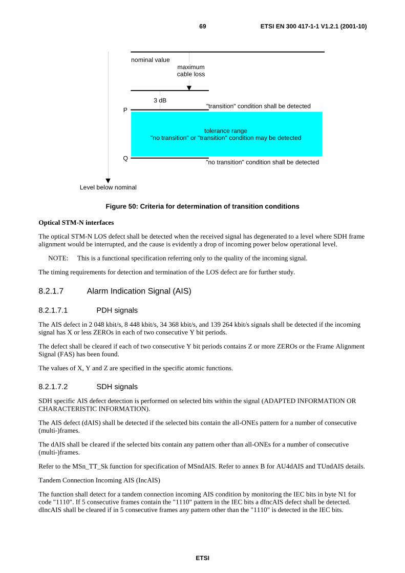
ETSI
ETSI EN 300 417-1-1 V1.2.1 (2001-10)69
"transition" condition shall be detected
"no transition" condition shall be detected
nominal valuemaximumcable loss
tolerance range"no transition" or "transition" condition may be detected
Q
P
3 dB
Level below nominal
Figure 50: Criteria for determination of transition conditions
Optical STM-N interfaces
The optical STM-N LOS defect shall be detected when the received signal has degenerated to a level where SDH frame alignment would be interrupted, and the cause is evidently a drop of incoming power below operational level.
NOTE: This is a functional specification referring only to the quality of the incoming signal.
The timing requirements for detection and termination of the LOS defect are for further study.
8.2.1.7 Alarm Indication Signal (AIS)
8.2.1.7.1 PDH signals
The AIS defect in 2 048 kbit/s, 8 448 kbit/s, 34 368 kbit/s, and 139 264 kbit/s signals shall be detected if the incoming signal has X or less ZEROs in each of two consecutive Y bit periods.
The defect shall be cleared if each of two consecutive Y bit periods contains Z or more ZEROs or the Frame Alignment Signal (FAS) has been found.
The values of X, Y and Z are specified in the specific atomic functions.
8.2.1.7.2 SDH signals
SDH specific AIS defect detection is performed on selected bits within the signal (ADAPTED INFORMATION OR CHARACTERISTIC INFORMATION).
The AIS defect (dAIS) shall be detected if the selected bits contain the all-ONEs pattern for a number of consecutive (multi-)frames.
The dAIS shall be cleared if the selected bits contain any pattern other than all-ONEs for a number of consecutive (multi-)frames.
Refer to the MSn_TT_Sk function for specification of MSndAIS. Refer to annex B for AU4dAIS and TUndAIS details.
Tandem Connection Incoming AIS (IncAIS)
The function shall detect for a tandem connection incoming AIS condition by monitoring the IEC bits in byte N1 for code "1110". If 5 consecutive frames contain the "1110" pattern in the IEC bits a dIncAIS defect shall be detected. dIncAIS shall be cleared if in 5 consecutive frames any pattern other than the "1110" is detected in the IEC bits.

ETSI
ETSI EN 300 417-1-1 V1.2.1 (2001-10)70
NOTE: Bits 1 to 4 of byte N1 support two applications: conveying the incoming error information and conveying the incoming AIS information to the TC tail end. Codes 0000 to 1101, 1111 represent IncAIS is false, code 1110 represents IncAIS is true.
Tandem connection incoming AIS condition by monitoring bit 4 in byte N2 for code "1". If 5 consecutive frames contain the value "1" in bit 4 a dIncAIS defect shall be detected. dIncAIS shall be cleared if in 5 consecutive frames value "0" is detected in bit 4 of byte N2.
8.2.1.8 Loss of frame, multiframe, pointer, tandem connection, sequence structure
STM-N LOF
Refer to specific atomic functions.
The frame alignment shall be found by searching for the A1, A2 bytes contained in the STM-N signal. The framing pattern searched for may be a subset of the A1 and A2 bytes contained on the STM-N signal. The frame signal shall be continuously checked with the presumed frame start position for the alignment. If in the In-Frame state (IF), the maximum Out-Of-Frame (OOF) detection time shall be 625 µs for a random unframed signal. The algorithm used to check the alignment shall be such that, under normal conditions, a 10-3 (Poisson type) error ratio will not cause a false OOF more then once per 6 minutes. If in the OOF state, the maximum frame alignment time shall be 250 µs for an error-free signal with no emulated framing patterns. The algorithm used to recover from the OOF state shall be such, that the probability for false frame recovery with a random unframed signal shall be no more than 10-5 per 250 µs time interval.
In Frame(IF)
Out Of Frame(OOF)
max 5 Errored FASs
2 Error Free FASs
Figure 51: Frame alignment process
The frame start signal (RS1_CI_FS) shall be maintained during the OOF state and only updated upon successful transition form OOF to the IF state.
If the OOF anomaly persists for 3 ms, a STM-1 Loss Of Frame defect (dLOF) shall be detected. To provide for the case of intermittent OOFs, the integrating timer shall not be reset to zero until an IF condition persists continuously for 3 ms. The dLOF defect shall be cleared when the IF state persists continuously for 3 ms.
Loss Of FrameCleared
(dLOF=false)
Loss Of FrameSet
(dLOF=true)
Out Of Frame for >3ms
In Frame for >3ms
NOTE: Out-Of-Frame integrating timer is not reset to zero until an In-Frame condition persists continuously for 3 ms.
Figure 52: Loss of frame process
PDH LOF
Refer to specific atomic functions.
TUG structure LOM
If the TUG structure contains TUG-2s, the 500 µs (multi)frame start phase shall be recovered performing multi-frame alignment on bits 7 and 8 of byte H4 (VC-4) or bits 6 and 7 of byte MA (Pqs, q=4,31). Out-of-multiframe (OOM) shall be assumed once when an error is detected in the H4 bit 7 and 8 [MA bit 6 and 7] sequence. Multiframe alignment shall be assumed to be recovered, and the in-multiframe (IM) state shall be entered, when in four consecutive VC-4 [Pqs] frames an error free H4 [MA] sequence is found.
ETSI
ETSI EN 300 417-1-1 V1.2.1 (2001-10)71
If the multiframe alignment process is in the OOM state and the multiframe is not recovered within X ms, a dLOM defect shall be declared. Once in a dLOM state, this state shall be exited when the multiframe is recovered (multiframe alignment process enter the IM state). X shall be a value in the range 1 ms to 5 ms. X is not configurable.
AU-4 & TU-m (m=3,2,12) LOP
Refer to annex B.
LTC
The tandem connection multiframe alignment shall be found by searching for the pattern "1111 1111 1111 1110" within the bits 7 and 8 of the network operator byte. The signal shall be continuously checked with the presumed multiframe start position for the alignment.
Frame alignment is deemed to have been lost (entering Out Of Multiframe (OOM) state) when two consecutive FAS are detected in error (i.e. ≥ 1 error in each FAS).
Frame alignment is deemed to have been recovered (entering In Multiframe (IM) state) when one non-errored FAS is found.
The loss of tandem connection defect (dLTC) shall be detected if the multiframe alignment process is in the OOM state. The dLTC shall be cleared if the multiframe alignment process is in the IM state.
LSS
The loss of PRBS lock defect (dLSS) shall be detected according the criteria defined in ITU-T Recommendation O.151 [39], clause 2.6.
8.2.1.9 Failure of protocol
The failure of protocol requirements are for further study.
8.2.1.10 Equipment defects
Equipment defects (dEQ) may imply great performance impairments; i.e. signal transfer interruption. These defects which are implementation specific cannot be listed here explicitly. Nevertheless, equipment defects shall be reported per replaceable unit.
For the case where a replaceable unit is reported as being faulty (i.e. it contains an equipment fault) all the signals processed on that unit shall be assumed to be interrupted. The trail termination sink functions on that unit shall represent this by means of the activation of their performance parameter pN_DS. This will result in the reporting of (severely) errored seconds or, more likely, unavailable seconds.
NOTE: The effect of equipment redundancy (replaceable unit protection) has to be included in the specification. This is for further study.
8.2.1.11 Transmit Fail
This defect is no longer required.
8.2.1.12 Loss of Tandem Connection Unequipped (dUNEQ)
The Tandem Connection unequipped defect (dUNEQ) shall be detected if five consecutive frames contain the "0000 0000" pattern in the network operator byte. The dUNEQ defect shall be cleared if in five consecutive frames any pattern other than the "0000 0000" is detected in the network operator byte.

ETSI
ETSI EN 300 417-1-1 V1.2.1 (2001-10)72
8.2.2 Consequent action filter f2
This clause describes the consequent actions that can be generated by an atomic function within an NE as a result of anomalies/defects.
After a defect (see note) is detected, one or more of the following consequent actions may be requested:
NOTE: For the case of REI, it is after anomaly detection.
- all-ONEs (AIS) insertion;
- RDI insertion;
- insert REI;
- unequipped signal insertion;
- generation of "Server Signal Fail (SSF)" signal;
- generation of "Trail Signal Fail (TSF)" signal;
- generation of "Trail Signal Degrade (TSD)" signal;
- (Automatic) Laser Shutdown (ALS/LS).
Table 7: Consequent action request generation in trail termination, adaptation and connection functions
Termination sink Adaptation sink Connection aAIS aAIS insert unequipped VC aTSF aSSF aTSD aRDI aREI aODI aOEI
Figure 53 shows how the aAIS, aRDI and aREI consequent action request signals control the associated consequent actions: insertion of all-ONEs, insertion of RDI code and insertion of REI value. Figure 53 also shows the location of aSSF, aTSF and aTSD consequent action requests.
Detected defects cause the insertion of the all-ONEs signal in Trail Termination sink functions. Detected defects cause the insertion of the all-ONEs signal in adaptation sink functions. The reception of a Server Signal Fail (SSF) indication causes the insertion of all-ONEs in the adaptation source. Refer to clause 8.2.2.1 for details.
In case where the all-ONEs signal is inserted either in a trail termination sink or in the previous adaptation sink function, the RDI code is inserted in the associated trail termination source signal. I.e. the RDI code is inserted on detected defects or the reception of a SSF indication in a trail termination sink function (aRDI). Refer to clause 8.2.2.2 for details.
Every frame, the number of detected EDC violations (aREI) in the trail termination sink function is inserted in the REI bits in the associated trail termination source signal. Refer to clause 8.2.2.3 for details.

ETSI
ETSI EN 300 417-1-1 V1.2.1 (2001-10)73
all-ONEs
aAISData
AdaptationSource
all-ONEsaAIS
aSSFData
AdaptationSink
Data
Data TSF
AUaAISTUaAIS
Data
Data
Data SSF
all-ONEsaAIS
aTSFData
aRDIaREI
TrailTermination
Sink
TrailTermination
Source
aTSD
CI_SSFCI_D CI_D CI_SSF
SSF
AI_TSFAI_D AI_D
AI_DAI_D AI_TSFAI_TSD
CI_D CI_SSF CI_D
RI_RDI
RI_REI
Figure 53: Consequent Action control: AIS, RDI and REI
A connection function inserts the unequipped VC signal at one of its outputs if that output is not connected to one of its inputs. Refer to clause 8.2.2.7.
The behaviour of PDH path layer connection functions if an output is not connected to one of the inputs is for further study.
8.2.2.1 Alarm Indication Signal (AIS)
The all-ONEs (AIS) signal replaces the received signal under detected defect conditions in order to prevent downstream failures being declared and alarms being raised. Refer to clause 7.5 for a description of the application and the insertion control.
The logic equations for the all-ONEs (aAIS) insertion request are (generically):
- adaptation sink functions
aAIS ←←←← dPLM or dLOA or dAIS
NOTE 1: dLOA represents either dLOF, or dLOM or dLOP whichever is applicable in the atomic function.
- termination sink functions
aAIS ←←←← dAIS or dUNEQ/dLOS or dTIM
NOTE 2: The term dAIS is applicable for the MS_TT function. The term dLOS is applicable for physical section layer termination functions while dUNEQ represents a similar condition for the (SDH) path layers.
- adaptation source functions
aAIS ←←←← CI_SSF

ETSI
ETSI EN 300 417-1-1 V1.2.1 (2001-10)74
The termination sink, and adaptation sink and source functions shall insert the all-ONEs (AIS) signal within 2 (multi)frames after AIS request generation (aAIS), and cease the insertion within 2 (multi)frames after the AIS request has cleared.
8.2.2.2 Remote Defect Indicator (RDI)
Refer to clause 7.4.1 for a description of the RDI application and the insertion control.
The logic equation for the RDI insertion request is (generically):
aRDI ←←←← dAIS/CI_SSF or dUNEQ or dTIM
NOTE 1: In general Trail Termination functions do not detect dAIS. (The exception is the MS Trail Termination.) To ensure that the Trail Termination function is aware of the reception of the all-ONEs signal, the server layer (which inserted the all-ONEs signal on detected defect conditions) informs the client layer about this condition by means of the CI_SSF signal. In such case the dAIS term, in the aRDI expression, is replaced by CI_SSF.
NOTE 2: In the termination supervision (TTs_Sk) function aRDI ← CI_SSF or dTIM.
The trail termination source function shall insert the RDI code within the timelimits given below after the RDI request generation (aRDI)) in the trail termination sink function. It ceases RDI code insertion within the timelimits given below after the RDI request has cleared.
MSn_TT: 1ms
S4_TT, S3_TT: 1ms
S2_TT, S12_TT, S11_TT: 4ms
S4D_TT, S3D_TT: 20ms
S2D_TT, S12D_TT, S11D_TT: 80ms
P4s_TT, P31s_TT: 1ms
P12s_TT: 5ms
P4e_TT: 900µs
P31e_TT: 800µs
P22e_TT: 600µs
8.2.2.3 Remote Error Indication (REI)
Refer to clause 7.4.2 for a description of the REI application and the insertion control.
The logic equation for the REI insertion request is (generically):
aREI ←←←← "#EDCV"
The trail termination source function inserts the REI value within the timelimits below in the REI bit(s).
MSn_TT: 1 ms
S4_TT, S3_TT: 1 ms
S2_TT, S12_TT, S11_TT: 4 ms
S4D_TT, S3D_TT: 20 ms
S2D_TT, S12D_TT, S11D_TT: 80 ms
ETSI
ETSI EN 300 417-1-1 V1.2.1 (2001-10)75
P4s_TT, P31s_TT: 1 ms
P12s_TT: 1 s
8.2.2.4 Server Signal Fail (SSF)
CI_SSF signals are used to forward the defect condition of the server to the client in the next (sub-) layer, to:
- prevent defect detection in layers without incoming AIS detectors in trail termination sink functions (e.g. S4_TT, S12_TT);
- report the server signal fail condition in layers without incoming AIS detectors in trail termination sink functions;
- control the link connection AIS (e.g. AU-AIS) insertion in adaptation source functions;
- initiate protection switching/restoration in the (protection-)connection function.
The logic equation for SSF is (generically):
- aSSF ←←←← dPLM or dAIS/AI_TSF or dLOA
NOTE 1: In case the adaptation function does not detect the AIS defect, the dAIS term will be replaced by AI_TSF generated by the previous TT_Sk.
NOTE 2: The term dLOA is the general indication for dLOF, dLOM or dLOP whichever is applicable.
8.2.2.5 Trail Signal Fail (TSF)
AI_TSF signals are used to forward the defect condition of the trail to the:
- adaptation sink function, to control all-ONEs (AIS) insertion in the function, when the function does not perform AIS defect detection; e.g. in S12/P12x_A_Sk;
- protection connection function in the trail protection sub layer, to initiate trail protection switching in that function;
- connection function in the same layer which performs a non-intrusively monitored SNC (SNC/N) protection scheme, to initiate SNC protection switching in that function. Refer to clause 9.4.2.
The logic equation for TSF is (generically):
- aTSF ← dAIS/CI_SSF or dUNEQ/dLOS or dTIM
NOTE 1: In general trail termination functions do not detect dAIS (the exception is the MS trail termination). To ensure that the trail termination function is aware of the reception of the all-ONEs signal, the server layer (which inserted the all-ONEs signal on detected defect conditions) informs the client layer about this condition by means of the CI_SSF signal. In such case the dAIS term, in the aTSF expression, is replaced by CI_SSF.
NOTE 2: In the termination supervision (TTs_Sk) function aTSF ← CI_SSF or (not dUNEQ) or dTIM.
8.2.2.6 Trail Signal Degrade (TSD)
aTSD signals are used to forward the signal degrade defect condition of the trail to the:
- protection connection function in the trail protection sub layer, to initiate trail protection switching in that function;
- connection function in the layer to initiate sub-network connection protection switching in that function for the case of a non-intrusive monitored SNC (SNC/N) protection scheme. Refer to clause 9.4.2.
The logic equation for TSD is:
- aTSD ←←←← dDEG
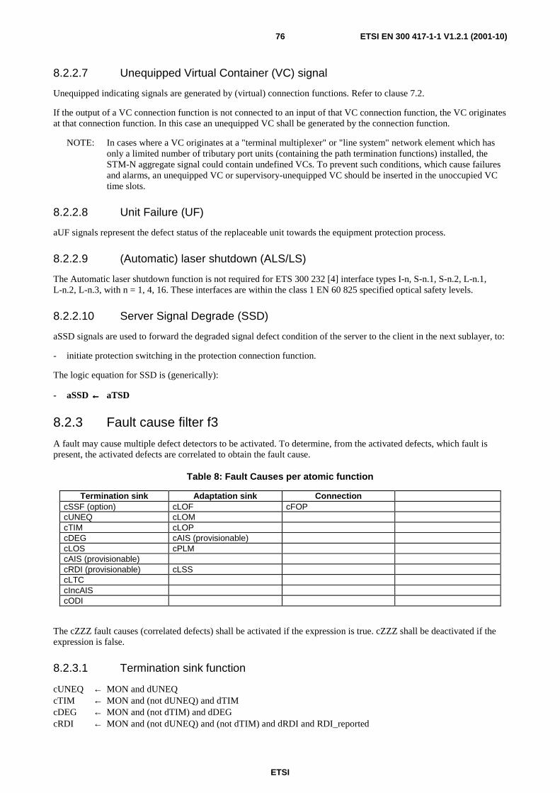
ETSI
ETSI EN 300 417-1-1 V1.2.1 (2001-10)76
8.2.2.7 Unequipped Virtual Container (VC) signal
Unequipped indicating signals are generated by (virtual) connection functions. Refer to clause 7.2.
If the output of a VC connection function is not connected to an input of that VC connection function, the VC originates at that connection function. In this case an unequipped VC shall be generated by the connection function.
NOTE: In cases where a VC originates at a "terminal multiplexer" or "line system" network element which has only a limited number of tributary port units (containing the path termination functions) installed, the STM-N aggregate signal could contain undefined VCs. To prevent such conditions, which cause failures and alarms, an unequipped VC or supervisory-unequipped VC should be inserted in the unoccupied VC time slots.
8.2.2.8 Unit Failure (UF)
aUF signals represent the defect status of the replaceable unit towards the equipment protection process.
8.2.2.9 (Automatic) laser shutdown (ALS/LS)
The Automatic laser shutdown function is not required for ETS 300 232 [4] interface types I-n, S-n.1, S-n.2, L-n.1, L-n.2, L-n.3, with n = 1, 4, 16. These interfaces are within the class 1 EN 60 825 specified optical safety levels.
8.2.2.10 Server Signal Degrade (SSD)
aSSD signals are used to forward the degraded signal defect condition of the server to the client in the next sublayer, to:
- initiate protection switching in the protection connection function.
The logic equation for SSD is (generically):
- aSSD ←←←← aTSD
8.2.3 Fault cause filter f3
A fault may cause multiple defect detectors to be activated. To determine, from the activated defects, which fault is present, the activated defects are correlated to obtain the fault cause.
Table 8: Fault Causes per atomic function
Termination sink Adaptation sink Connection cSSF (option) cLOF cFOP cUNEQ cLOM cTIM cLOP cDEG cAIS (provisionable) cLOS cPLM cAIS (provisionable) cRDI (provisionable) cLSS cLTC cIncAIS cODI
The cZZZ fault causes (correlated defects) shall be activated if the expression is true. cZZZ shall be deactivated if the expression is false.
8.2.3.1 Termination sink function
cUNEQ ← MON and dUNEQ cTIM ← MON and (not dUNEQ) and dTIM cDEG ← MON and (not dTIM) and dDEG cRDI ← MON and (not dUNEQ) and (not dTIM) and dRDI and RDI_reported
ETSI
ETSI EN 300 417-1-1 V1.2.1 (2001-10)77
cSSF ← MON and CI_SSF/dAIS and SSF_Reported cLOS ← MON and dLOS cAIS ← MON and dAIS and AIS_Reported It shall be provisionable to report SSF as a fault cause. This is controlled by means of the parameter SSF_reported. The default shall be SSF_Reported = false.
It shall be provisionable to report RDI as a fault cause. This is controlled by means of the parameter RDI_reported. The default shall be RDI_Reported = false.
It shall be provisionable to report AIS as a fault cause. This is controlled by means of the parameter AIS_reported. The default shall be AIS_Reported = false.
NOTE 1: dUNEQ, dTIM, dDEG and dRDI are cleared during an CI_SSF/AI_TSF condition. Refer to clauses 8.2.1.2 to 8.2.1.5.
NOTE 2: In the MS_TT function, defects of the server layer are detected by dAIS from the K2 byte and not through CI_SSF.
NOTE 3: By default, AIS as such is not reported. Instead trail terminations shall report (as an option) that the server (layer) failed to pass the signal (Server Signal Fail) if they receive the all-ONEs (AIS) signal. This reduces the declaration of "AIS failures" to one failure (fSSF) at the Trail Termination NE. No failures are generated at intermediate nodes in the (long) trail. Refer to clause 7.7.2.
NOTE 4: Refer to clause 8.5 for a MON description.
8.2.3.2 Termination supervisory sink function
cUNEQ ← MON and dTIM and (AcTI = all "0"s) and dUNEQ cTIM ← MON and dTIM and not (dUNEQ and AcTI = all "0"s) cDEG ← MON and (not dTIM) and dDEG cRDI ← MON and (not dTIM) and dRDI and RDI_reported cSSF ← MON and CI_SSF and SSF_Reported It shall be provisionable to report SSF as a fault cause. This is controlled by means of the parameter SSF_reported. The default shall be SSF_Reported = false.
It shall be provisionable to report RDI as a fault cause. This is controlled by means of the parameter RDI_reported. The default shall be RDI_Reported = false.
NOTE 1: dUNEQ, dTIM, dDEG and dRDI are cleared during an CI_SSF/AI_TSF condition. Refer to clauses 8.2.1.2 to 8.2.1.5.
NOTE 2: the detection of an unequipped VC signal is possible in a termination supervisory sink function despite both the supervisory-unequipped VC signal and the unequipped VC signal have signal label code "0". A trace identifier mismatch will be detected with the accepted trace identifier being all-ZEROs. This combination is the signature of the reception of an unequipped VC.
NOTE 3: Refer to clause 8.5 for a MON description.
8.2.3.3 Adaptation sink function
cPLM ← dPLM and (not AI_TSF) cAIS ← dAIS and (not AI_TSF) and (not dPLM) and AIS_Reported cLOA ← dLOA and (not dAIS) and (not dPLM) It shall be provisionable to report AIS as a fault cause. This is controlled by means of the parameter AIS_reported. The default shall be AIS_Reported = false.
NOTE 1: dLOA represents dLOF, dLOP or dLOM, whichever is applicable.
NOTE 2: The specification of the Pointer Interpreter algorithm is such that either dAIS or dLOP can be declared, not both at the same time. Refer to annex B.
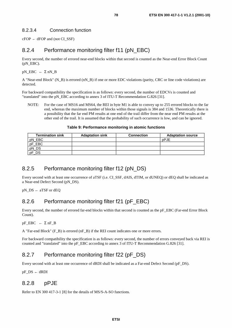
ETSI
ETSI EN 300 417-1-1 V1.2.1 (2001-10)78
8.2.3.4 Connection function
cFOP ← dFOP and (not CI_SSF)
8.2.4 Performance monitoring filter f11 (pN_EBC)
Every second, the number of errored near-end blocks within that second is counted as the Near-end Error Block Count (pN_EBC).
pN_EBC ← Σ nN_B
A "Near-end Block" (N_B) is errored (nN_B) if one or more EDC violations (parity, CRC or line code violations) are detected.
For backward compatibility the specification is as follows: every second, the number of EDCVs is counted and "translated" into the pN_EBC according to annex 3 of ITU-T Recommendation G.826 [31].
NOTE: For the case of MS16 and MS64, the REI in byte M1 is able to convey up to 255 errored blocks to the far end, whereas the maximum number of blocks within those signals is 384 and 1536. Theoretically there is a possibility that the far end PM results at one end of the trail differ from the near end PM results at the other end of the trail. It is assumed that the probability of such occurrence is low, and can be ignored.
Table 9: Performance monitoring in atomic functions
Termination sink Adaptation sink Connection Adaptation source pN_EBC pPJE pF_EBC pN_DS pF_DS
8.2.5 Performance monitoring filter f12 (pN_DS)
Every second with at least one occurrence of aTSF (i.e. CI_SSF, dAIS, dTIM, or dUNEQ) or dEQ shall be indicated as a Near-end Defect Second (pN_DS).
pN_DS ← aTSF or dEQ
8.2.6 Performance monitoring filter f21 (pF_EBC)
Every second, the number of errored far-end blocks within that second is counted as the pF_EBC (Far-end Error Block Count).
pF_EBC ← Σ nF_B
A "Far-end Block" (F_B) is errored (nF_B) if the REI count indicates one or more errors.
For backward compatibility the specification is as follows: every second, the number of errors conveyed back via REI is counted and "translated" into the pF_EBC according to annex 3 of ITU-T Recommendation G.826 [31].
8.2.7 Performance monitoring filter f22 (pF_DS)
Every second with at least one occurrence of dRDI shall be indicated as a Far-end Defect Second (pF_DS).
pF_DS ← dRDI
8.2.8 pPJE
Refer to EN 300 417-3-1 [8] for the details of MS/S-A-SO functions.
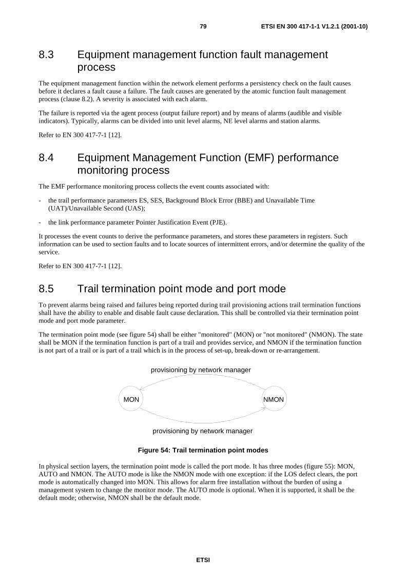
ETSI
ETSI EN 300 417-1-1 V1.2.1 (2001-10)79
8.3 Equipment management function fault management process
The equipment management function within the network element performs a persistency check on the fault causes before it declares a fault cause a failure. The fault causes are generated by the atomic function fault management process (clause 8.2). A severity is associated with each alarm.
The failure is reported via the agent process (output failure report) and by means of alarms (audible and visible indicators). Typically, alarms can be divided into unit level alarms, NE level alarms and station alarms.
Refer to EN 300 417-7-1 [12].
8.4 Equipment Management Function (EMF) performance monitoring process
The EMF performance monitoring process collects the event counts associated with:
- the trail performance parameters ES, SES, Background Block Error (BBE) and Unavailable Time (UAT)/Unavailable Second (UAS);
- the link performance parameter Pointer Justification Event (PJE).
It processes the event counts to derive the performance parameters, and stores these parameters in registers. Such information can be used to section faults and to locate sources of intermittent errors, and/or determine the quality of the service.
Refer to EN 300 417-7-1 [12].
8.5 Trail termination point mode and port mode To prevent alarms being raised and failures being reported during trail provisioning actions trail termination functions shall have the ability to enable and disable fault cause declaration. This shall be controlled via their termination point mode and port mode parameter.
The termination point mode (see figure 54) shall be either "monitored" (MON) or "not monitored" (NMON). The state shall be MON if the termination function is part of a trail and provides service, and NMON if the termination function is not part of a trail or is part of a trail which is in the process of set-up, break-down or re-arrangement.
MON NMON
provisioning by network manager
provisioning by network manager
Figure 54: Trail termination point modes
In physical section layers, the termination point mode is called the port mode. It has three modes (figure 55): MON, AUTO and NMON. The AUTO mode is like the NMON mode with one exception: if the LOS defect clears, the port mode is automatically changed into MON. This allows for alarm free installation without the burden of using a management system to change the monitor mode. The AUTO mode is optional. When it is supported, it shall be the default mode; otherwise, NMON shall be the default mode.

ETSI
ETSI EN 300 417-1-1 V1.2.1 (2001-10)80
MON NMONprovisioning by
network manager
provisioning bynetwork manager
AUTO
provisioning bynetwork manager
provisioning bynetwork manager
provisioning bynetwork manager
automatic bynetwork element
on clearing of dLOS
Figure 55: Port modes
8.6 Access point mode To prevent alarms being raised and failures being reported during payload and multiplex structure modification actions in an active trail, adaptation functions may have the ability to enable and disable fault cause declaration. This may be controlled via an access point mode (APmode) parameter. This is for further study.
9 Protection process
9.1 Introduction NOTE: Three TS are under preparation (RTS/TM-1070 for TS 101 009 [40] V1.1.2, RTS/TM-1071 for
TS 100 746 and DTS/TM-1076) which generically address protection switching. When the study has been completed and TS approved and published, it is intended to align this clause with the TS. Therefore, the contents of this clause reflect the current situation in ITU-T Recommendations and may be subjected to future modification.
The protection process is based on the philosophy underlying the functional model of ITU-T Recommendation G.803 [27]:
- clause 9.2 introduces general characteristic parameters of protection;
- clause 9.3 specifies functional models of trail protection types;
- clause 9.4 specifies functional models of sub-network connection types;
- clause 9.5 specifies equipment protection.
Care should be taken when reading this section not to confuse the terms "sub-layer" and "sub-network".
9.2 General A protection application makes use of pre-assigned capacity between nodes. The simplest architecture has 1 working and 1 protection capacity (1+1), the most complex architecture has n working and m protection capacities (m:n).
A restoration application makes use of any capacity available between nodes. In general the algorithms used for restoration will involve re-routeing. When restoration is used, some percentage of the transport network capacity will be reserved for re-routeing working traffic. Restoration is initiated by the network operator and as such does not fall within the scope of the present document.

ETSI
ETSI EN 300 417-1-1 V1.2.1 (2001-10)81
Several types of protection can be distinguished. They are categorized into two classes: trail and SNC protection:
Trail protection: a defect condition in a layer initiates reconfiguration switching in the same layer. The following trail protection types are recognized:
- linear trail protection;
- Shared Protection RING (SPRING) protection.
Trail protection is characterized by the expansion of the trail termination function into a new sub-layer (see clause 5.4) known as the protection sub-layer.
Sub-Network Connection (SNC) protection: a defect condition in a layer initiates reconfiguration switching in the client layer. The following SNC protection types can be recognized:
- Inherently monitored Sub-Network Connection (SNC/I) protection;
- Non-intrusively monitored Sub-Network Connection (SNC/N) protection;
- Sublayer monitored Sub-Network Connection (SNC/S) protection.
The protection types are characterized by the following parameters:
- protection architecture (1+1, 1:n, m:n);
- switching type (uni-directional, bi-directional);
- Automatic Protection Switch (APS) channel (provisioning, usage, coding);
- operation type (non-revertive, revertive);
- protection switch requests;
- hold off timer;
- protection switch performance;
- protection switch state machine.
9.2.1 Protection architectures
Protection processes are allocated to the Connection functions (C) in each layer and to the sub-layer Protection Connection functions (P_C) in the expanded trail termination. Connection functions implement SNC protection, protection connection functions implement trail protection.
The NE at the source end of the protection span transmits the protected group as a protection group. The NE at the sink end of the protection span outputs the received protection group as the protected group. In case no defects are detected in the working SNC/trail signals, these signals are selected as the normal signals. The protection SNCs/trails may in this case transport extra traffic.
The SNCs/trails selected by the sink end are called the active SNCs/trails. The others are called the standby SNCs/trails.
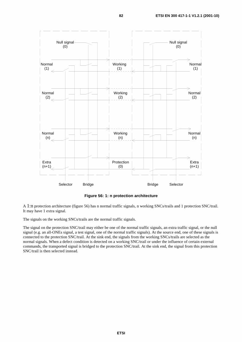
ETSI
ETSI EN 300 417-1-1 V1.2.1 (2001-10)82
Selector Bridge SelectorBridge
Protection(0)
Extra(n+1)
Extra(n+1)
Working(n)
Normal(n)
Normal(n)
Normal(2)
Normal(2)
Working(2)
Normal(1)
Normal(1)
Working(1)
Null signal(0)
Null signal(0)
Figure 56: 1: n protection architecture
A 1:n protection architecture (figure 56) has n normal traffic signals, n working SNCs/trails and 1 protection SNC/trail. It may have 1 extra signal.
The signals on the working SNCs/trails are the normal traffic signals.
The signal on the protection SNC/trail may either be one of the normal traffic signals, an extra traffic signal, or the null signal (e.g. an all-ONEs signal, a test signal, one of the normal traffic signals). At the source end, one of these signals is connected to the protection SNC/trail. At the sink end, the signals from the working SNCs/trails are selected as the normal signals. When a defect condition is detected on a working SNC/trail or under the influence of certain external commands, the transported signal is bridged to the protection SNC/trail. At the sink end, the signal from this protection SNC/trail is then selected instead.
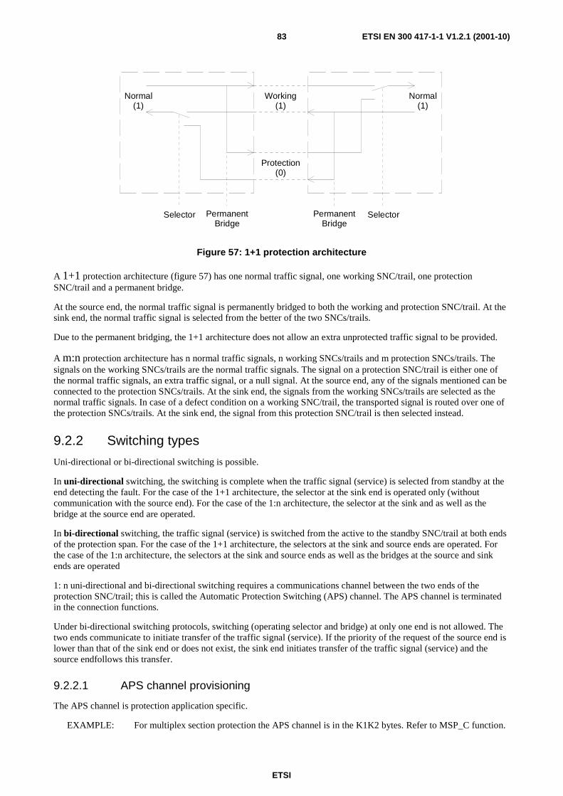
ETSI
ETSI EN 300 417-1-1 V1.2.1 (2001-10)83
Selector PermanentBridge
SelectorPermanentBridge
Working(1)
Protection(0)
Normal(1)
Normal(1)
Figure 57: 1+1 protection architecture
A 1+1 protection architecture (figure 57) has one normal traffic signal, one working SNC/trail, one protection SNC/trail and a permanent bridge.
At the source end, the normal traffic signal is permanently bridged to both the working and protection SNC/trail. At the sink end, the normal traffic signal is selected from the better of the two SNCs/trails.
Due to the permanent bridging, the 1+1 architecture does not allow an extra unprotected traffic signal to be provided.
A m:n protection architecture has n normal traffic signals, n working SNCs/trails and m protection SNCs/trails. The signals on the working SNCs/trails are the normal traffic signals. The signal on a protection SNC/trail is either one of the normal traffic signals, an extra traffic signal, or a null signal. At the source end, any of the signals mentioned can be connected to the protection SNCs/trails. At the sink end, the signals from the working SNCs/trails are selected as the normal traffic signals. In case of a defect condition on a working SNC/trail, the transported signal is routed over one of the protection SNCs/trails. At the sink end, the signal from this protection SNC/trail is then selected instead.
9.2.2 Switching types
Uni-directional or bi-directional switching is possible.
In uni-directional switching, the switching is complete when the traffic signal (service) is selected from standby at the end detecting the fault. For the case of the 1+1 architecture, the selector at the sink end is operated only (without communication with the source end). For the case of the 1:n architecture, the selector at the sink and as well as the bridge at the source end are operated.
In bi-directional switching, the traffic signal (service) is switched from the active to the standby SNC/trail at both ends of the protection span. For the case of the 1+1 architecture, the selectors at the sink and source ends are operated. For the case of the 1:n architecture, the selectors at the sink and source ends as well as the bridges at the source and sink ends are operated
1: n uni-directional and bi-directional switching requires a communications channel between the two ends of the protection SNC/trail; this is called the Automatic Protection Switching (APS) channel. The APS channel is terminated in the connection functions.
Under bi-directional switching protocols, switching (operating selector and bridge) at only one end is not allowed. The two ends communicate to initiate transfer of the traffic signal (service). If the priority of the request of the source end is lower than that of the sink end or does not exist, the sink end initiates transfer of the traffic signal (service) and the source endfollows this transfer.
9.2.2.1 APS channel provisioning
The APS channel is protection application specific.
EXAMPLE: For multiplex section protection the APS channel is in the K1K2 bytes. Refer to MSP_C function.
ETSI
ETSI EN 300 417-1-1 V1.2.1 (2001-10)84
9.2.2.2 APS channel usage
The use of the APS channel is protection application specific.
9.2.2.3 APS channel coding
The APS channel coding is protection application specific, and is specified in the associated atomic (protection_)connection function.
NOTE: All application specific codings for linear protection switching architectures are based on a generic (superset) state machine. Refer to annex A of EN 300 417-3-1 [8].
9.2.3 Operation types
Revertive or non-revertive operation is possible.
In revertive operation, the traffic signal (service) always returns to (or remains on) the working SNC/trail if the switch requests are terminated. I.e. when the working SNC/trail has recovered from the defect or the external request is cleared.
In non-revertive operation, the traffic signal (service) does not return to the working SNC/trail if the switch requests are terminated.
9.2.4 Protection switch requests
Automatic protection switching is based on the defect conditions of the working and protection SNCs/trails. These defect conditions result in the generation of Signal Fail (SF) and signal degrade (SD) signals (refer to supervisory process, clauses 8.2.2.4, 8.2.2.5 and 8.2.2.6).
Protection switch requests can be differentiated by their origin:
- near-end:
- SF and SD conditions;
- external requests: Clear, Lockout, Forced Switch, Manual Switch and Exercise;
- state: Wait-To-Restore, Do Not Revert, No request and Reverse Request;
- far-end:
- SF and SD conditions;
- external requests: Lockout, Forced Switch, Manual Switch and Exercise;
- state: Wait-To-Restore, Do Not Revert, No request and Reverse Request.
The Clear, Lockout, Forced Switch #i, Manual Switch #i, Exercise, and other requests are defined in annex A of EN 300 417-3-1 [8].
9.2.5 Protection switch performance
One of the characteristics of protection is that switching times are relatively fast compared to restoration.
Protection switching shall be completed within the switch-over time X of reception of a SF or SD signal that initiates a switch. The value of X depends on the protection type and the network layer that it applies to and is specified in the atomic functions (e.g. for multiplex section protection X is 50 ms).
The service interruption due to the switching on an external request shall be limited to the switch-over time X.

ETSI
ETSI EN 300 417-1-1 V1.2.1 (2001-10)85
9.2.6 Protection switch state machine
The protection switch state machine (algorithm) is protection application specific, and is specified in the associated atomic (protection_) connection function.
NOTE: All application specific codings could be based on a generic (superset) state machine. This is for further study.
9.2.7 Protection connection function (I/O and processes)
A connection function which performs a protection function has the following inputs and outputs and internal processes (see figure 58):
- Data (D), Clock (CK), Frame Start (FS), Signal Fail (SF) and Signal Degrade (SD) per Working/Protection input signal. For the case of bi-directional and 1:n uni-directional switching, at least one APS signal per protection group;
- D, CK, FS and SF per Normal/Extra output signal;
- D, CK, FS and SF per Working/Protection output signal. For the case of bi-directional and 1:n uni-directional switching, at least one APS signal per protection group;
- D, CK, and FS per Normal/Extra input signal;
- connection matrix and unequipped VC generation processes;
- APS channel processor process;
- control process.
Connectionmatrix Control
APS channelprocessor
CI_aSSF/aSSDor
AI_aTSF/aTSD
CI_D/CK/FS/aSSF
CI_D/CK/FS/aSSF CI_APS
MI
(1 or more APS channelsdepending on protection
switch type).
uneqVCTI_CK/FS
Figure 58: Possible processes within a connection function
9.2.8 Hold Off timer
Hold-off times are useful to stagger protection switching activation between various transport layers or within the same transport layer. It shall be possible to provision for each protection group (see 9.2.1) whether or not a holdoff timer is enabled. The objective is that the holdoff time should be selectable per protection group on an individual basis. As a minimum, a single holdoff time per layer shall be supported, applicable for all protection groups within that layer.
A hold-off timer is started when a defect condition is declared and runs for a non-resettable period which is provisional from 0 to 10 seconds in steps of 100ms. When the timer expires, protection switching is initiated if a defect condition is still present at this point. Note that a defect condition does not have to be present for the entire duration of the hold-off period, only the state at the expiry of the hold-off timer is relevant. Further, the defect that triggers the hold-off timer does not need to be of the same type as the one at the expiry of the hold-off period.
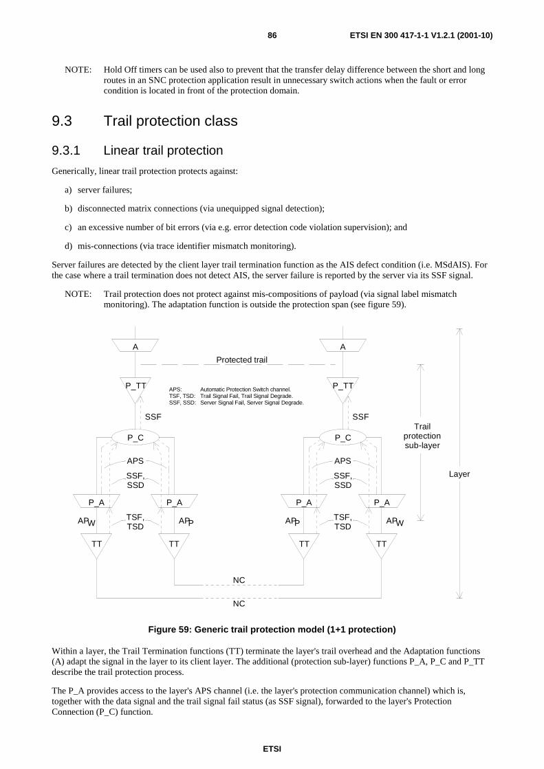
ETSI
ETSI EN 300 417-1-1 V1.2.1 (2001-10)86
NOTE: Hold Off timers can be used also to prevent that the transfer delay difference between the short and long routes in an SNC protection application result in unnecessary switch actions when the fault or error condition is located in front of the protection domain.
9.3 Trail protection class
9.3.1 Linear trail protection
Generically, linear trail protection protects against:
a) server failures;
b) disconnected matrix connections (via unequipped signal detection);
c) an excessive number of bit errors (via e.g. error detection code violation supervision); and
d) mis-connections (via trace identifier mismatch monitoring).
Server failures are detected by the client layer trail termination function as the AIS defect condition (i.e. MSdAIS). For the case where a trail termination does not detect AIS, the server failure is reported by the server via its SSF signal.
NOTE: Trail protection does not protect against mis-compositions of payload (via signal label mismatch monitoring). The adaptation function is outside the protection span (see figure 59).
P_A P_A
P_TT
P_C
TT TT
A
TSF,TSD
SSF,SSD
APS
SSF
APW APP
P_A P_A
P_TT
P_C
TT TT
A
TSF,TSD
SSF,SSD
APS
SSF
AP WAPP
Protected trail
NC
NC
Trailprotectionsub-layer
Layer
Automatic Protection Switch channel.Trail Signal Fail, Trail Signal Degrade.Server Signal Fail, Server Signal Degrade.
APS:TSF, TSD:SSF, SSD:
Figure 59: Generic trail protection model (1+1 protection)
Within a layer, the Trail Termination functions (TT) terminate the layer's trail overhead and the Adaptation functions (A) adapt the signal in the layer to its client layer. The additional (protection sub-layer) functions P_A, P_C and P_TT describe the trail protection process.
The P_A provides access to the layer's APS channel (i.e. the layer's protection communication channel) which is, together with the data signal and the trail signal fail status (as SSF signal), forwarded to the layer's Protection Connection (P_C) function.

ETSI
ETSI EN 300 417-1-1 V1.2.1 (2001-10)87
The APS is terminated in the P_C, while the selected data signal and its SSF are output.
The P_TT sink passes the received data signal and reports its status (loss of trail, or otherwise) as indicated by the SSF signal.
EXAMPLE: An example of a protected trail is the protected multiplex section trail (i.e. MSP).
9.3.2 SPRING protection
Figure 60 shows the MS SPRING protection. The dashed lines show the connections in the case of a protection switch (defect) condition in the West and the East SNCs.
n/2 x n/2 x
MSn/S4
MSPn MSPn
MSn/S4
MSn/MSPn
MSn
MSPn
n/2APS SSF, SSD
TSF, TSD
NCWest
n/2 x n/2 x
MSn/S4
MSPn MSPn
MSn/S4
MSn/MSPn
MSn
n/2 APSSSF, SSD
TSF, TSD
NCEast
S4
To/From S4_TT or MSn/S4_A
W P WP
TrailProtectionSub-layer
MSnLayer
VC-4Layer
Figure 60: Multiplex section shared protection ring (without protection access, dash-dot-dash lines in MSPn_C show protection routing)
Multiplex section shared protection rings are characterized by dividing the total payload per multiplex section equally into working and protection capacity, e.g. for MS-N SPRING there are N/2 Administrative Unit Groups (AUGs) available for working and N/2 AUGs for protection.
The notation of "sharing" refers to the fact that the ring protection capacity can be shared by any multiplex section of a multinode ring under a section or node fault condition. Sharing of protection capacity may lead to improved traffic carrying capacity under normal conditions over other ring protection types.
Under non-fault conditions, the protection capacity can be used to carry extra (low priority) traffic. This is shown in figure 61 by means of the dash-dot-dash lines and atomic functions.
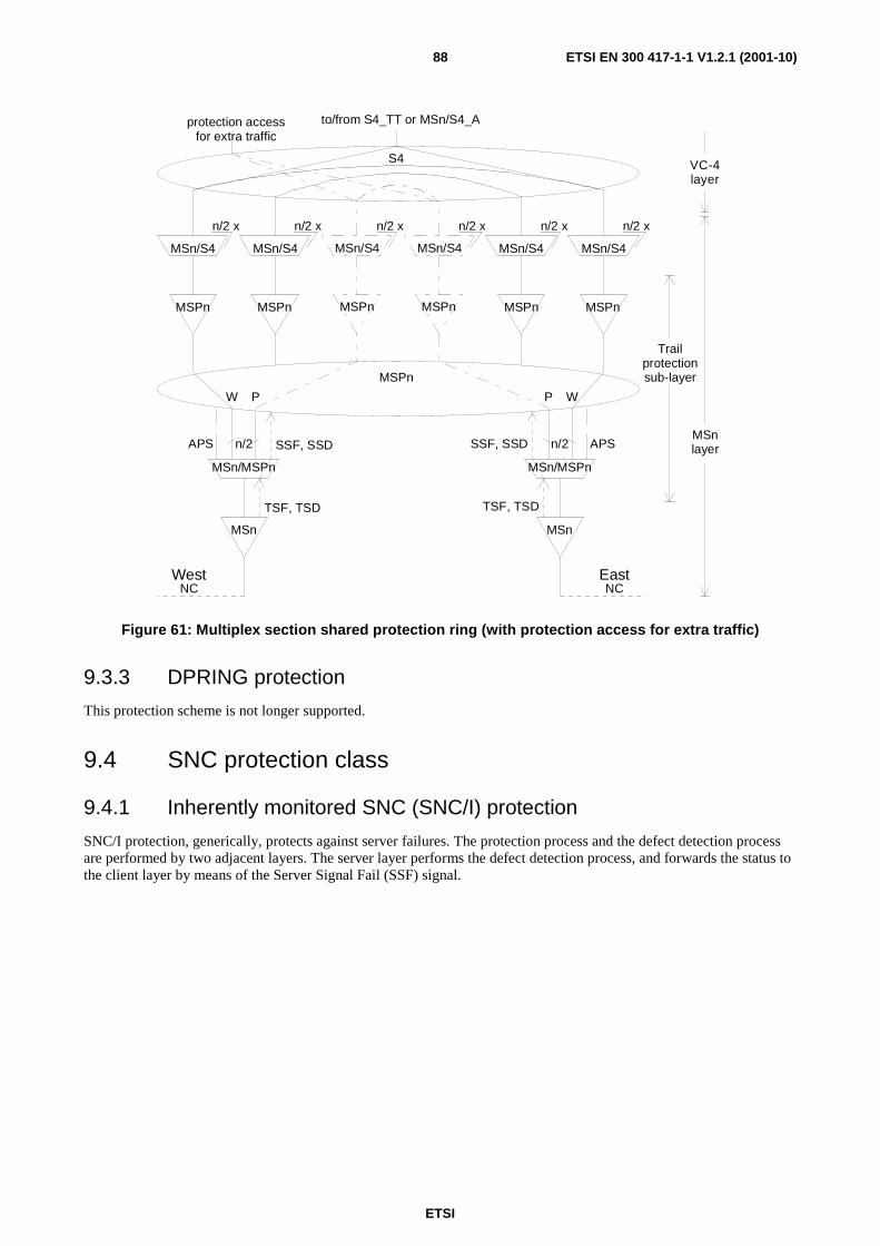
ETSI
ETSI EN 300 417-1-1 V1.2.1 (2001-10)88
MSn/MSPn
MSn
MSPn
n/2APS SSF, SSD
TSF, TSD
NCWest
S4
to/from S4_TT or MSn/S4_A
W P
n/2 x n/2 x
MSn/S4
MSPn MSPn
MSn/S4
MSn/MSPn
MSn
n/2 APSSSF, SSD
TSF, TSD
NCEast
WP
n/2 x n/2 x
MSn/S4
MSPn MSPn
MSn/S4
n/2 x n/2 x
MSn/S4
MSPn MSPn
MSn/S4
protection accessfor extra traffic
Trailprotectionsub-layer
MSnlayer
VC-4layer
Figure 61: Multiplex section shared protection ring (with protection access for extra traffic)
9.3.3 DPRING protection
This protection scheme is not longer supported.
9.4 SNC protection class
9.4.1 Inherently monitored SNC (SNC/I) protection
SNC/I protection, generically, protects against server failures. The protection process and the defect detection process are performed by two adjacent layers. The server layer performs the defect detection process, and forwards the status to the client layer by means of the Server Signal Fail (SSF) signal.
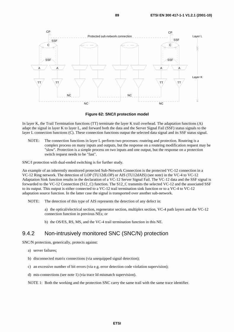
ETSI
ETSI EN 300 417-1-1 V1.2.1 (2001-10)89
A A
C
TT TT
SSF
SSF
NC
NC
A A
C
TT TT
SSF
SSF
NC
NC
Protected sub-network connection
CP CP
Layer K
Layer L
Figure 62: SNC/I protection model
In layer K, the Trail Termination functions (TT) terminate the layer K trail overhead. The adaptation functions (A) adapt the signal in layer K to layer L, and forward both the data and the Server Signal Fail (SSF) status signals to the layer L connection functions (C). These connection functions output the selected data signal and its SSF status signal.
NOTE: The connection functions in layer L perform two processes: routeing and protection. Routeing is a complex process on many inputs and outputs, but the response on a routeing modification request may be "slow". Protection is a simple process on two inputs and one output, but the response on a protection switch request needs to be "fast".
SNC/I protection with dual-ended switching is for further study.
An example of an inherently monitored protected Sub-Network Connection is the protected VC-12 connection in a VC-12 Ring network. The detection of LOP (TU12dLOP) or AIS (TU12dAIS) (see note) in the VC-4 to VC-12 Adaptation Sink function results in the declaration of a VC-12 Server Signal Fail. The VC-12 data and the SSF signal is forwarded to the VC-12 Connection (S12_C) function. The S12_C transmits the selected VC-12 and the associated SSF to its output. This output is either connected to a VC-12 trail termination sink function or to a VC-4 to VC-12 adaptation source function. In the latter case the signal is transported over another sub-network.
NOTE: The detection of this type of AIS represents the detection of any defect in:
a) the optical/electrical section, regenerator section, multiplex section, VC-4 path layers and the VC-12 connection function in previous NEs; or
b) the OS/ES, RS, MS, and the VC-4 trail termination function in this NE.
9.4.2 Non-intrusively monitored SNC (SNC/N) protection
SNC/N protection, generically, protects against:
a) server failures;
b) disconnected matrix connections (via unequipped signal detection);
c) an excessive number of bit errors (via e.g. error detection code violation supervision);
d) mis-connections (see note 1) (via trace Id mismatch supervision).
NOTE 1: Both the working and the protection SNC carry the same trail with the same trace identifier.
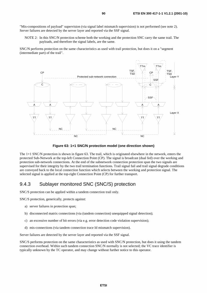
ETSI
ETSI EN 300 417-1-1 V1.2.1 (2001-10)90
"Mis-compositions of payload" supervision (via signal label mismatch supervision) is not performed (see note 2). Server failures are detected by the server layer and reported via the SSF signal.
NOTE 2: In this SNC/N protection scheme both the working and the protection SNC carry the same trail. The payloads, and therefore the signal labels, are the same.
SNC/N performs protection on the same characteristics as used with trail protection, but does it on a "segment (intermediate part) of the trail".
A A
C
TT TT
NC
NC
A A
SSF
SSF
NC
NC
Protected sub-network connection
CP CP
Layer X
Layer Y
TTm TTm
TT TT
C
TSF,TSD
TSF,TSD
Figure 63: 1+1 SNC/N protection model (one direction shown)
The 1+1 SNC/N protection is shown in figure 63. The trail, which is originated elsewhere in the network, enters the protected Sub-Network at the top-left Connection Point (CP). The signal is broadcast (dual fed) over the working and protection sub-network connections. At the end of the subnetwork connection protection span the two signals are supervised for their integrity by the two trail termination functions. Trail signal fail and trail signal degrade conditions are conveyed back to the local connection function which selects between the working and protection signal. The selected signal is applied at the top-right Connection Point (CP) for further transport.
9.4.3 Sublayer monitored SNC (SNC/S) protection
SNC/S protection can be applied within a tandem connection trail only.
SNC/S protection, generically, protects against:
a) server failures in protection span;
b) disconnected matrix connections (via (tandem connection) unequipped signal detection);
c) an excessive number of bit errors (via e.g. error detection code violation supervision);
d) mis-connections (via tandem connection trace Id mismatch supervision).
Server failures are detected by the server layer and reported via the SSF signal.
SNC/S performs protection on the same characteristics as used with SNC/N protection, but does it using the tandem connection overhead. Within such tandem connection SNC/N normally is not selected; the VC trace identifier is typically unknown by the TC operator, and may change without further notice to this operator.
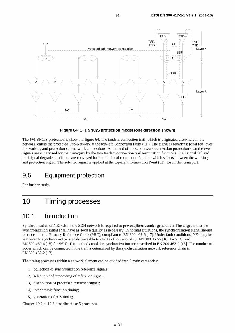
ETSI
ETSI EN 300 417-1-1 V1.2.1 (2001-10)91
A A
C
TT TT
NC
NC
A A
SSF
SSF
NC
NC
Protected sub-network connection
CP CP
Layer X
Layer Y
TTDm TTDm
TT TT
C
TSF,TSD
TSF,TSD
Figure 64: 1+1 SNC/S protection model (one direction shown)
The 1+1 SNC/S protection is shown in figure 64. The tandem connection trail, which is originated elsewhere in the network, enters the protected Sub-Network at the top-left Connection Point (CP). The signal is broadcast (dual fed) over the working and protection sub-network connections. At the end of the subnetwork connection protection span the two signals are supervised for their integrity by the two tandem connection trail termination functions. Trail signal fail and trail signal degrade conditions are conveyed back to the local connection function which selects between the working and protection signal. The selected signal is applied at the top-right Connection Point (CP) for further transport.
9.5 Equipment protection For further study.
10 Timing processes
10.1 Introduction Synchronization of NEs within the SDH network is required to prevent jitter/wander generation. The target is that the synchronization signal shall have as good a quality as necessary. In normal situations, the synchronization signal should be traceable to a Primary Reference Clock (PRC), compliant to EN 300 462-6 [17]. Under fault conditions, NEs may be temporarily synchronized by signals traceable to clocks of lower quality (EN 300 462-5 [16] for SEC, and EN 300 462-4 [15] for SSU). The methods used for synchronization are described in EN 300 462-2 [13]. The number of nodes which can be connected in the trail is determined by the synchronization network reference chain in EN 300 462-2 [13].
The timing processes within a network element can be divided into 5 main categories:
1) collection of synchronization reference signals;
2) selection and processing of reference signal;
3) distribution of processed reference signal;
4) inter atomic function timing;
5) generation of AIS timing.
Clauses 10.2 to 10.6 describe these 5 processes.

ETSI
ETSI EN 300 417-1-1 V1.2.1 (2001-10)92
10.2 Synchronization timing collection Figure 65 describes the synchronization time collection process. Two classes of synchronization reference inputs can be recognized:
- external synchronization reference inputs;
- internal synchronization reference inputs.
MS-N
RS-N
OS-N/ES-1 T12
Synchronisation distribution layer
STM-N 2 048 kbit/s 2 048 kHz
SD SDSDn1 x
n2 x
n3 x
E12
P12s
OSC
34 368 kbit/s
SD
n4 x
E31
P31s
139 264 kbit/s
SD
n5 x
E4
P4s
Figure 65: Synchronization timing collection
10.2.1 External synchronization reference inputs
The NE can derive its timing from one of a number of external sources (figure 65). The physical characteristics of these interfaces shall conform to the following:
- Optical STM-N interfaces, shall conform to ITU-T Recommendation G.957 [35]. Electrical STM-1 interfaces shall conform to ITU-T Recommendation G.703 [21], clause 15. The S1 byte within the MSOH of each STM-N shall be used to convey Synchronization Status Messages (SSM). Jitter and wander requirements as specified in EN 302 084 [19].
- 2 048 kbit/s interfaces shall conform to ITU-T Recommendation G.703 [21], clause 9 and to the jitter and wander requirements as specified in clause 11.3.2.3. It shall be possible to designate a 2 048 kbit/s interface as a synchronization source irrespective of whether the interface is carrying traffic or not. The case of a 2 048 kbit/s interface with a Synchronization Status Message is for further study.
- External 2 048 kHz synchronization interfaces shall conform to ITU-T Recommendation G.703 [21], clause 13 and jitter and wander requirements as specified in clause 11.3.2.3.
- 34 368 kbit/s interfaces shall conform to recommendation G.703 [21] clause 11.
- 139 264 kbit/s interfaces shall conform to recommendation G.703 [21] clause 12.
NOTE: The frequency and jitter/wander tolerance of these synchronization signals are constrained by the requirements of the client layer.
The number of selectable interfaces, both concerning the number of different types and the number of each type (n1, n2, n3, n4, n5 in figure 65) is implementation specific.

ETSI
ETSI EN 300 417-1-1 V1.2.1 (2001-10)93
10.2.2 Internal synchronization reference input
The NE shall also provide an internal oscillator which optionally could be selected as the NE timing signal.
10.3 Synchronization timing selection and processing
10.3.1 Synchronization reference source selection
Two selection processes are active in this SD layer. Selection of the reference signal to synchronize the system clock, and selection of the reference clock to forward to the synchronization reference output interface.
Each synchronization reference input signal has a quality level associated with it and is assigned a unique priority level. The selection process shall automatically select the synchronization source for the NE based on a selection algorithm which uses the defect status of the synchronization reference source signals, the quality indication indicated by the SSM of the synchronization reference source signals, and the priority list. It selects from the 'set of signals with the highest quality' the one with 'the highest priority'.
NOTE: Defect detection in the SDH section layers result in the generation of an SSF signal at the output of the atomic function which has detected the defect. The insertion of this SSF signal is detected by the SSM process as the reception of a Quality Level 15 (QL15) condition; i.e. do not use this synchronization reference source signal.
10.3.2 Clock processing
Two clock processing levels are recognized; the SEC level and the SSU level.
These clock processing are defined in EN 300 462-4 [15] and EN 300 462-5 [16].
10.4 Synchronization timing distribution
P12s/P0P4s/Sm
P4s P12s
E12/P12s
E12
2 048 kbit/straffic &
sync output
E4
E4/P4s
139 264 kbit/straffic &
sync output
P12s/SD-type1P4s/SDMSn/S4 MSn/SD
MSn
RSn
RSn/MSn
OSn
OSn/RSn
STM-Ntraffic &
sync output
P4s_TI_CKP4s_TI_FS
P12s_TI_CKP12s_TI_FS
MSn_TI_CKMSn_TI_FS
SD_CI_QLSD_CI_CSSD_CI_SSF
P31s/S12 P31s/SD
P31s
E31
E31/P31s
34 368 kbit/straffic &
sync output
P31s_TI_CKP31s_TI_FS
P4s-LC P31s-LC P12s-LCMSn-LC
SD_CI_CK
SD_CI_QLSD_CI_CS
SD_CI_SSF
SD_CI_QLSD_CI_CS
SD_CI_SSF
SD_CI_QLSD_CI_CS
SD_CI_SSF
SD_CI_CK SD_CI_CK SD_CI_CK
traffic outputs carrying sync information
P12s/P0
P12s
E12/P12s
E12
2 048 kbit/straffic &
sync output
P12s/SD-type2
P12s_TI_CKP12s_TI_FS
P12s-LC SD_CI_QLSD_CI_CS
SD_CI_SSF
SD_CI_CK
MI_QLmin
Figure 66: Synchronization timing distribution (to be enhanced/aligned)

ETSI
ETSI EN 300 417-1-1 V1.2.1 (2001-10)94
10.4.1 Internal synchronization distribution interfaces
The synchronization timing reference generated in the synchronization distribution layer is distributed to the SDH adaptation source functions via the Timing Information (TI) signals (figure 66). These signals contain the Clock (TI_CK) and Frame Start (TI_FS) information. The elastic store processes in those adaptation source functions use these TI signals to read out the data. The SDH path layer connection functions use these signals to generate the unequipped VC signals.
10.4.2 Synchronization reference outputs
The NE may provide one or more external 2 048 kHz and/or 2 048 kbit/s synchronization output ports for use by external equipment, as determined by its Equipment Functional Specification. These interfaces shall conform to ITU-T Recommendation G.703 [21], clause 13, and clause 9, with jitter and wander requirements as specified in clause 11.3.1.3.
The 2 048 kbit/s synchronization interface is defined in EN 300 462-3 [14] clause 7.2.4.
10.5 Inter atomic function timing In a network element, three classes of clocks are present:
- the recovered clock signals;
- the locally generated clock signals;
- the smoothed clock signals.
10.6 AIS timing Sink direction
All-ONEs (AIS) insertion in the sink direction replaces the data signal by a local generated all-ONEs signal. The clock signal which generates this all-ONEs data signal can be the clock signal applied at the input of the atomic function; i.e. the CI_Sk_CK or AI_Sk_CK clock signal.
CI_CK
AI_CKAI_FS
CI_FS
framealigner
AI_FS AI_CKAI_D
CI_FSCI_CK
elasticstore
AI_FSAI_CK
CI_FS CI_CK
TI_CK
TI_FS
CI_D
"1"
AI_D
"1"
CI_D CI_D
"1"
AI_D
Figure 67: AIS timing

ETSI
ETSI EN 300 417-1-1 V1.2.1 (2001-10)95
Source direction
All-ONEs (AIS) insertion in the source direction replaces the data signal by an all-ONEs signal. This all-ONEs signal is generated by a local clock, which is:
- the S4_TI_CK for the case of AU4-AIS;
- the Sm_TI_CK for the case of TUm-AIS (m = 3,2,12,11);
- an ± 20 ppm accurate AIS oscillator, in the RSn/MSn_A_So function, for the case of MSn-AIS;
- an ± 15 ppm accurate AIS oscillator for the case of "140 Mbit/s-AIS";
- an ± 20 ppm accurate AIS oscillator for the case of "34 Mbit/s-AIS";
- an ± 30 ppm accurate AIS oscillator for the case of "8 Mbit/s-AIS";
- an ± 50 ppm accurate AIS oscillator for the case of "2 Mbit/s-AIS";
- an ± 100 ppm accurate AIS oscillator for the case of "64 kbit/s-AIS".
11 General performance This clause specifies requirements involving several functions together and between interfaces.
11.1 Availability objectives
11.1.1 General
For a network provider, the reliability of network elements is of prime concern as it directly influences the availability of connections. However, the availability of a connection depends not only on the reliability of the network elements themselves but also on the level of network redundancy. Furthermore, it depends on the restoration times of the equipment involved. The restoration times depend to a great extent on the Operation, Administration and Management (OAM) philosophy of the network provider.
A manufacturer has, in most cases, requirements from several operators to take into account. Requirements from a certain network provider will depend on the level of economic development of the country concerned, the degree of market competition, customer requirements, the level of network redundancy, the level of maintenance support, etc.
The basis for determining the availability of a network element should be the analytical method for dependability as described in ITU-T Recommendation E.862 [20].
The main point of the analytical method is that dependability aspects are taken into account as an economic factor. The level of availability is thus dimensioned according to cost-benefit analyses rather than by beforehand stated objectives.
The application of the method to network components is shown in the ITU-T handbook "Handbook on Quality of Service and Network Performance".
11.1.2 Parameters
The lifetime of an item can be divided into periods where the item is in an "up state" and can perform its task and periods where the item is out of order ("down state"). The related statistical measures are "Mean Time To Failure" (MTTF) and "Mean Down Time" (MDT).
Down times are not necessarily caused by failures but also by planned maintenance actions.
The asymptotic availability (A) of the item is calculated as:
A = MTTF/(MTTF + MDT) ≈ MTBF/(MTBF + MDT)
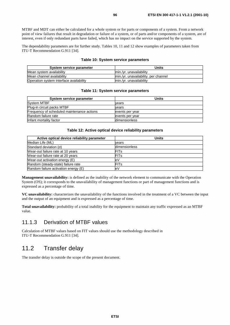
ETSI
ETSI EN 300 417-1-1 V1.2.1 (2001-10)96
MTBF and MDT can either be calculated for a whole system or for parts or components of a system. From a network point of view failures that result in degradation or failure of a system, or of parts and/or components of a system, are of interest, even if only redundant parts have failed, which has no impact on the service supported by the system.
The dependability parameters are for further study. Tables 10, 11 and 12 show examples of parameters taken from ITU-T Recommendation G.911 [34].
Table 10: System service parameters
System service parameter Units Mean system availability min./yr. unavailability Mean channel availability min./yr. unavailability. per channel Operation system interface availability min./yr. unavailability
Table 11: System service parameters
System service parameter Units System MTBF years Plug-in circuit packs MTBF years Frequency of scheduled maintenance actions events per year Random failure rate events per year Infant mortality factor dimensionless
Table 12: Active optical device reliability parameters
Active optical device reliability parameter Units Median Life (ML) years Standard deviation (σ) dimensionless Wear-out failure rate at 10 years FITs Wear-out failure rate at 20 years FITs Wear-out activation energy (E) eV Random (steady-state) failure rate FITs Random failure activation energy (E) eV
Management unavailability: is defined as the inability of the network element to communicate with the Operation System (OS); it corresponds to the unavailability of management functions or part of management functions and is expressed as a percentage of time.
VC unavailability: characterizes the unavailability of the functions involved in the treatment of a VC between the input and the output of an equipment and is expressed as a percentage of time.
Total unavailability: probability of a total inability for the equipment to maintain any traffic expressed as an MTBF value.
11.1.3 Derivation of MTBF values
Calculation of MTBF values based on FIT values should use the methodology described in ITU-T Recommendation G.911 [34].
11.2 Transfer delay The transfer delay is outside the scope of the present document.
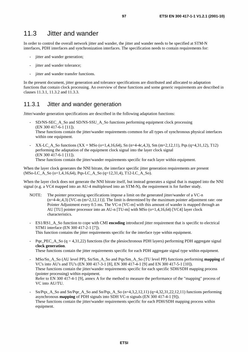
ETSI
ETSI EN 300 417-1-1 V1.2.1 (2001-10)97
11.3 Jitter and wander In order to control the overall network jitter and wander, the jitter and wander needs to be specified at STM-N interfaces, PDH interfaces and synchronization interfaces. The specification needs to contain requirements for:
- jitter and wander generation;
- jitter and wander tolerance;
- jitter and wander transfer functions.
In the present document, jitter generation and tolerance specifications are distributed and allocated to adaptation functions that contain clock processing. An overview of these functions and some generic requirements are described in clauses 11.3.1, 11.3.2 and 11.3.3.
11.3.1 Jitter and wander generation
Jitter/wander generation specifications are described in the following adaptation functions:
- SD/NS-SEC_A_So and SD/NS-SSU_A_So functions performing equipment clock processing (EN 300 417-6-1 [11]). These functions contain the jitter/wander requirements common for all types of synchronous physical interfaces within one equipment.
- XX-LC_A_So functions (XX = MSo (o=1,4,16,64), Sn (n=4-4c,4,3), Sm (m=2,12,11), Pqs (q=4,31,12), T12) performing the adaptation of the equipment clock signal into the layer clock signal (EN 300 417-6-1 [11]). These functions contain the jitter/wander requirements specific for each layer within equipment.
When the layer clock generates the NNI bitrate, the interface specific jitter generation requirements are present (MSo-LC_A_So (o=1,4,16,64), Pqs-LC_A_So (q=12,31,4), T12-LC_A_So).
When the layer clock does not generate the NNI bitrate itself, but instead generates a signal that is mapped into the NNI signal (e.g. a VC4 mapped into an AU-4 multiplexed into an STM-N), the requirement is for further study.
NOTE: The pointer processing specifications impose a limit on the generated jitter/wander of a VC-n (n=4-4c,4,3) [VC-m (m=2,12,11)]. The limit is determined by the maximum pointer adjustment rate: one Pointer Adjustment every 0.5 ms. The VC-n [VC-m] with this amount of wander is mapped through an AU [TU] pointer processor into an AU-n [TU-m] with MSo (o=1,4,16,64) [VC4] layer clock characteristics.
- ES1/RS1_A_So function to cope with CMI encoding introduced jitter requirement that is specific to electrical STM1 interface (EN 300 417-2-1 [7]). This function contains the jitter requirements specific for the interface type within equipment.
- Pqe_PEC_A_So (q = 4,31,22) functions (for the plesiochronous PDH layers) performing PDH aggregate signal clock generation. These functions contain the jitter requirements specific for each PDH aggregate signal type within equipment.
- MSo/Sn_A_So (AU level PP), Sn/Sm_A_So and Pqs/Sm_A_So (TU level PP) functions performing mapping of VC's into AU's and TU's (EN 300 417-3-1 [8], EN 300 417-4-1 [9] and EN 300 417-5-1 [10]). These functions contain the jitter/wander requirements specific for each specific SDH/SDH mapping process (pointer processing) within equipment. Refer to EN 300 417-4-1 [9], annex A for the method to measure the performance of the "mapping" process of VC into AU/TU.
- Sn/Pqx_A_So and Sn/Pqe_A_So and Sn/Pqs_A_So (n=4,3,2,12,11) (q=4,32,31,22,12,11) functions performing asynchronous mapping of PDH signals into SDH VC-n signals (EN 300 417-4-1 [9]). These functions contain the jitter/wander requirements specific for each PDH/SDH mapping process within equipment.

ETSI
ETSI EN 300 417-1-1 V1.2.1 (2001-10)98
- Sn/Pqx_A_Sk and Sn/Pqe_A_Sk and Sn/Pqs_A_Sk (n=4,3,2,12,11) (q=4,32,31,22,12,11) functions performing asynchronous demapping of PDH signals from SDH VC-n signals (EN 300 417-4-1 [9]). These functions contain the jitter/wander requirements specific for each PDH/SDH demapping process within equipment.
- Pne/Pqx_A_So and Pne/Pqe_A_So and Pne/Pqs_A_So (n,q=4,32,31,22,12,11) functions performing asynchronous mapping of PDH signals into aggregate PDH signals (EN 300 417-5-1 [10]). These functions contain the jitter/wander requirements specific for each PDH/PDH mapping process within equipment. Jitter/wander generation specifications (accuracy of stuff decisions) are for further study, and currently not addressed as current implementations do not cause problems.
- Pne/Pqx_A_Sk and Pne/Pqe_A_Sk and Pne/Pqs_A_Sk (n,q=4,32,31,22,12,11) functions performing asynchronous demapping of PDH signals from aggregate PDH signals (EN 300 417-5-1 [10]). These functions contain the jitter/wander generation requirements specific for each PDH/PDH demapping process within equipment. Jitter/wander generation requirements for Pne/Pqe_A_Sk and Pne/Pqs_A_Sk are for further study, and currently not addressed as current implementations do not cause problems.
- OSn/RSn_A_Sk functions performing clock recovery from the physical interface signal. These functions contain the jitter/wander generation requirements specific for each clock recovery process that determines the output clock of a regenerative repeater.
- Eq/Pqx_A_So, Eq/Pqe_A_So, Eq/Pqs_A_So functions have the requirement to not introduce any extra jitter/wander.
11.3.1.1 Jitter and wander generation on STM-N signals
Refer to EN 300 462-5 [16] for STM-N interfaces on SDH terminal equipment.
An SDH regenerator shall, on its STM-N output, not generate jitter in excess of the values in table 13.
Table 13: Jitter Generation for STM-N type A Regenerators in 2 048 kbit/s based networks
Interface Measurement Band (−−−−3 dB frequencies) (see notes 1 and 2)
Peak-peak amplitude (UI)
(see notes 3 and 4) high-pass (kHz) low-pass (MHz)
STM-1 optical 0,5 1,3 0,30 65 1,3 0,10
STM-4 optical 1 5 0,30 250 5 0,10
STM-16 optical 5 20 0,30 1 000 20 0,10
STM-64 optical Tbd tbd tbd Tbd tbd tbd
NOTE 1: The high-pass and low-pass measurement filter transfer functions are defined in clause 3 of ITU-T Recommendation G.825 [30].
NOTE 2: The measurement configuration is shown in figure 1 of ITU-T Recommendation G.825 [30].
NOTE 3: For STM-1: 1 UI = 6.43 ns For STM-4: 1 UI = 1.61 ns For STM-16: 1 UI = 0.40 ns
For STM-64: 1 UI = 0.10 ns NOTE 4: The measurement time and pass/fail criteria are defined in clause 3 of ITU-T
Recommendation G.825 [30].

ETSI
ETSI EN 300 417-1-1 V1.2.1 (2001-10)99
11.3.1.2 Jitter and wander generation on PDH interfaces
The SDH network may generate pointer justifications due to phase (frequency) differences in the network. The pointer justifications may cause large phase steps on the PDH interfaces if not processed in an appropriate way. The following clause gives five test sequences of pointers and two tables of requirements (see note 1) which refer to the different sequences (see note 2):
NOTE 1: The values in tables 14 and 15 are under study in ETSI STC TM 3.
NOTE 2: The test sequences have been agreed only for TU pointers. For the AU pointers the test sequences are under study in ETSI STC TM 3.
a) output jitter for a particular PDH interface in the absence of input jitter (either on the input PDH interface, the STM-N interface or on the synchronization interface) and in the absence of pointer adjustments: Test sequence A The requirements shall be met when the input frequency of the PDH interface is constant within the limits - a ppm to + a ppm from the nominal frequency. The value of "a" is defined in tables 14 and 15;
b) combined output jitter for a particular PDH interface in the absence of input jitter (either on the input PDH interface, the STM-N interface or on the synchronization interface). The pointer test sequence shall be one single AU/TU pointer adjustment of one polarity followed by a 10 s recovery time T1 and then a single AU/TU pointer adjustment of the opposite polarity (see figure 68). The requirement shall be met when the input frequency of the PDH interface is constant within the limits - a ppm to + a ppm from the nominal frequency. Value of "a" is defined in tables 14 and 15;
T1
T1
T3
T3
Figure 68: Test sequence B Figure 69: Test sequence C
c) combined output jitter for a particular PDH interface in the absence of input jitter (either on the input PDH interface, the STM-N interface or on the synchronization interface). The pointer test sequence shall be a double AU/TU pointer adjustment of one polarity followed by a 10 s recovery time T1 and then a double AU/TU pointer adjustment of the opposite polarity (see figure 69). The requirement shall be met when the input frequency of the PDH interface is constant within the limits - a ppm to + a ppm from the nominal frequency. Value of "a" is defined in tables 14 and 15;
d) combined output jitter for a particular PDH interface in the absence of input jitter (either on the input PDH interface, the STM-N interface or on the synchronization interface). The pointer test sequence shall be regularly occurring AU/TU pointer adjustments of the same polarity plus a single pointer adjustment of the same polarity, T3 seconds after a regular one (see figure 70). The requirements shall be met when the input frequency of the PDH interface is constant within the limits - a ppm to + a ppm from the nominal frequency. Value of "a" is defined in tables 14 and 15;
T2T3
T2 missingpointer
adjustment
Figure 70: Test sequence D Figure 71: Test sequence E
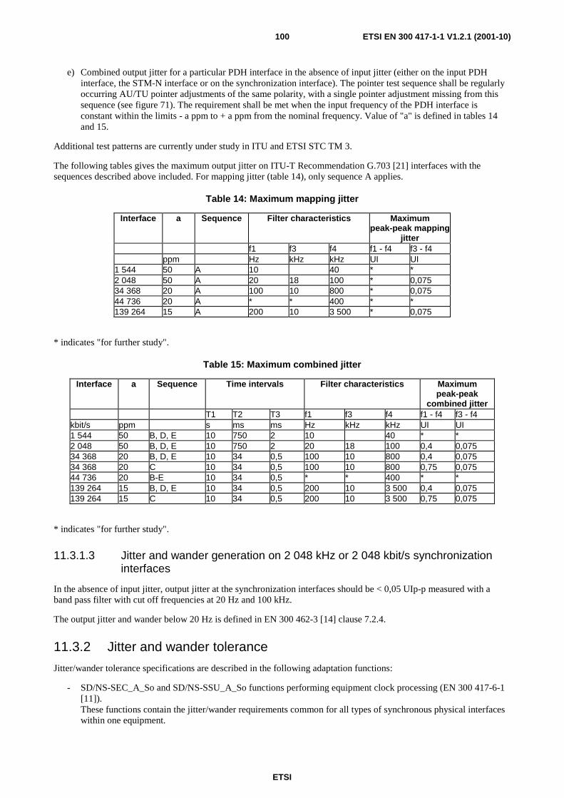
ETSI
ETSI EN 300 417-1-1 V1.2.1 (2001-10)100
e) Combined output jitter for a particular PDH interface in the absence of input jitter (either on the input PDH interface, the STM-N interface or on the synchronization interface). The pointer test sequence shall be regularly occurring AU/TU pointer adjustments of the same polarity, with a single pointer adjustment missing from this sequence (see figure 71). The requirement shall be met when the input frequency of the PDH interface is constant within the limits - a ppm to + a ppm from the nominal frequency. Value of "a" is defined in tables 14 and 15.
Additional test patterns are currently under study in ITU and ETSI STC TM 3.
The following tables gives the maximum output jitter on ITU-T Recommendation G.703 [21] interfaces with the sequences described above included. For mapping jitter (table 14), only sequence A applies.
Table 14: Maximum mapping jitter
Interface a Sequence Filter characteristics Maximum peak-peak mapping
jitter f1 f3 f4 f1 - f4 f3 - f4 ppm Hz kHz kHz UI UI 1 544 50 A 10 40 * * 2 048 50 A 20 18 100 * 0,075 34 368 20 A 100 10 800 * 0,075 44 736 20 A * * 400 * * 139 264 15 A 200 10 3 500 * 0,075
* indicates "for further study".
Table 15: Maximum combined jitter
Interface a Sequence Time intervals Filter characteristics Maximum peak-peak
combined jitter T1 T2 T3 f1 f3 f4 f1 - f4 f3 - f4 kbit/s ppm s ms ms Hz kHz kHz UI UI 1 544 50 B, D, E 10 750 2 10 40 * * 2 048 50 B, D, E 10 750 2 20 18 100 0,4 0,075 34 368 20 B, D, E 10 34 0,5 100 10 800 0,4 0,075 34 368 20 C 10 34 0,5 100 10 800 0,75 0,075 44 736 20 B-E 10 34 0,5 * * 400 * * 139 264 15 B, D, E 10 34 0,5 200 10 3 500 0,4 0,075 139 264 15 C 10 34 0,5 200 10 3 500 0,75 0,075
* indicates "for further study".
11.3.1.3 Jitter and wander generation on 2 048 kHz or 2 048 kbit/s synchronization interfaces
In the absence of input jitter, output jitter at the synchronization interfaces should be < 0,05 UIp-p measured with a band pass filter with cut off frequencies at 20 Hz and 100 kHz.
The output jitter and wander below 20 Hz is defined in EN 300 462-3 [14] clause 7.2.4.
11.3.2 Jitter and wander tolerance
Jitter/wander tolerance specifications are described in the following adaptation functions:
- SD/NS-SEC_A_So and SD/NS-SSU_A_So functions performing equipment clock processing (EN 300 417-6-1 [11]). These functions contain the jitter/wander requirements common for all types of synchronous physical interfaces within one equipment.

ETSI
ETSI EN 300 417-1-1 V1.2.1 (2001-10)101
- MSo/Sn_A_So (AU level PP), Sn/Sm_A_So and Pqs/Sm_A_So (TU level PP) functions performing mapping of VC's into AU's and TU's (EN 300 417-3-1 [8], EN 300 417-4-1 [9] and EN 300 417-5-1 [10]). These functions contain the jitter/wander requirements specific for each specific SDH/SDH mapping process (pointer processing) within equipment. Jitter/wander tolerance are defined for the part that concerns most: acceptance of worst case incoming pointer adjustments. In the absence of problems, no activity exists in this area.
- Sn/Pqx_A_So and Sn/Pqe_A_So and Sn/Pqs_A_So (n=4,3,2,12,11) (q=4,32,31,22,12,11) functions performing asynchronous mapping of PDH signals into SDH VC-n signals (EN 300 417-4-1 [9]). These functions contain the jitter/wander requirements specific for each PDH/SDH mapping process within equipment. Jitter tolerance requirements are defined and determine the minimum buffer size.
- Sn/Pqx_A_Sk and Sn/Pqe_A_Sk and Sn/Pqs_A_Sk (n=4,3,2,12,11) (q=4,32,31,22,12,11) functions performing asynchronous demapping of PDH signals from SDH VC-n signals (EN 300 417-4-1 [9]). These functions contain the jitter/wander requirements specific for each PDH/SDH demapping process within equipment. Jitter/wander tolerance requirements are defined for the part that concerns most: the effect of pointer adjustments.
- Pne/Pqx_A_So and Pne/Pqe_A_So and Pne/Pqs_A_So (n,q=4,32,31,22,12,11) functions performing asynchronous mapping of PDH signals into aggregate PDH signals (EN 300 417-5-1 [10]). These functions contain the jitter/wander requirements specific for each PDH/PDH mapping process within equipment. Jitter/wander tolerance requirements are defined and determine the minimum buffer size.
- Pne/Pqx_A_Sk and Pne/Pqe_A_Sk and Pne/Pqs_A_Sk (n,q=4,32,31,22,12,11) functions performing asynchronous demapping of PDH signals from aggregate PDH signals (EN 300 417-5-1 [10]). These functions contain the jitter/wander tolerance requirements specific for each PDH/PDH demapping process within equipment. Jitter/wander tolerance requirements for Pne/Pqe_A_Sk and Pne/Pqs_A_Sk are for further study, and currently not addressed as current implementations do not cause problems.
- OSn/RSn_A_Sk, ESn/RSn_A_Sk, Eq/Pqx_A_Sk, Eq/Pqe_A_Sk, Eq/Pqs_A_Sk functions performing clock recovery from the physical interface signal. These functions contain the jitter/wander tolerance requirements specific for each SDH or PDH clock recovery process within equipment.
11.3.2.1 Jitter and wander tolerance on optical interfaces
STM-N input jitter and wander tolerance is specified in clause 6.6 of EN 302 084 [19].
11.3.2.2 Jitter and wander tolerance on PDH interfaces
PDH interfaces input jitter and wander tolerance is specified in clause 6 of EN 302 084 [19].
11.3.2.3 Jitter and wander tolerance on 2 048 kHz synchronization interfaces
Jitter and wander tolerance are defined in EN 300 462-4 [15] and 5 [16] for SSU and SEC.
11.3.2.4 Pattern dependence testing
STM-N signals contain regions within the data stream where the possibility of bit errors being introduced is greater due to the structure of the data within these regions.
Three cases in particular may be identified:
1) errors resulting from eye-closure due to the tendency for the mean level of the signal within the equipment to vary with pattern-density due to alternative current couplings ("DC wander");
2) errors due to failure of the timing recovery circuit to bridge regions of data containing very little timing information in the form of data transitions;
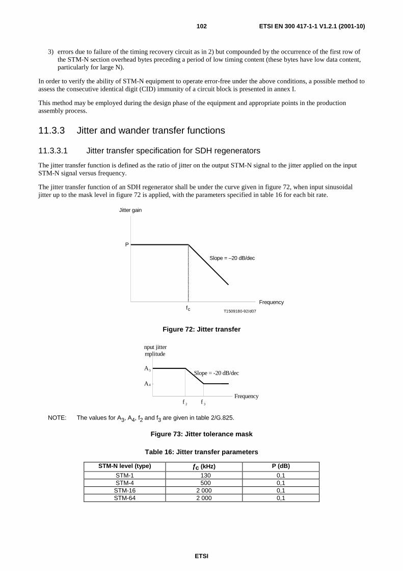
ETSI
ETSI EN 300 417-1-1 V1.2.1 (2001-10)102
3) errors due to failure of the timing recovery circuit as in 2) but compounded by the occurrence of the first row of the STM-N section overhead bytes preceding a period of low timing content (these bytes have low data content, particularly for large N).
In order to verify the ability of STM-N equipment to operate error-free under the above conditions, a possible method to assess the consecutive identical digit (CID) immunity of a circuit block is presented in annex I.
This method may be employed during the design phase of the equipment and appropriate points in the production assembly process.
11.3.3 Jitter and wander transfer functions
11.3.3.1 Jitter transfer specification for SDH regenerators
The jitter transfer function is defined as the ratio of jitter on the output STM-N signal to the jitter applied on the input STM-N signal versus frequency.
The jitter transfer function of an SDH regenerator shall be under the curve given in figure 72, when input sinusoidal jitter up to the mask level in figure 72 is applied, with the parameters specified in table 16 for each bit rate.
P
fc T1509180-92/d07
Frequency
Jitter gain
Slope = –20 dB/dec
Figure 72: Jitter transfer
F r e q u e n c y
n p u t j i t t e r m p l i t u d e
A
A
f f
4
3
2 3
S l o p e = - 2 0 d B / d e c
NOTE: The values for A3, A4, f2 and f3 are given in table 2/G.825.
Figure 73: Jitter tolerance mask
Table 16: Jitter transfer parameters
STM-N level (type) ƒƒƒƒc (kHz) P (dB)
STM-1 0130 0,1 STM-4 0500 0,1
STM-16 2 000 0,1 STM-64 2 000 0,1

ETSI
ETSI EN 300 417-1-1 V1.2.1 (2001-10)103
11.3.3.2 Jitter transfer specification for SDH multiplex equipment
The specific requirements for jitter transfer functions in SDH terminal equipment are applicable to the SEC or SSU compound function and specified in EN 300 462-5 [16] and 4 [15].
11.3.4 Performance on synchronization reference change-over
The change-over of synchronization from one source to another (each traceable to the same PRC) shall be performed so that the resultant frequency/phase change on synchronization outputs is compliant with the MRTIE mask defined in EN 300 462-5 [16].
The transition between synchronization sources may introduce a phase transient which may result in the generation of AU/TU pointer adjustments but should not introduce bit errors.
11.4 Error performance The general error performance design objective is that no errors shall be introduced by the SDH equipment when operating within specified limits under the most adverse environmental conditions as specified in ETS 300 019.
The specific requirement is that, when operating within specified limits under any combination of the environmental conditions given in ETS 300 019, the equipment should be capable of providing a level of performance which is consistent with the support of paths meeting the performance classification identified in ITU-T Recommendations G.821 [29], G.826 [31] and G.828 [41].
11.5 Blocking factor The blocking factor is equipment specific.
11.6 Connection set-up time The connection set-up time is defined as the sum of two components:
a) the message processing delay, which represents the time between the reception of a message on the Q interface port of the equipment and the generation of the corresponding primitive in the management communication layer function; and
b) the matrix set-up delay, which corresponds to the time taken from the generation of a primitive in the management communication layer function to the corresponding change of transport information at the NNI.
It is useful to distinguish between two different cases:
a) the set-up of new paths;
b) the set-up of preset paths,
which may invoke different management facilities and have different associated time constraints.
The specific requirements for connection set-up time are for further study.
ETSI
ETSI EN 300 417-1-1 V1.2.1 (2001-10)104
Annex A (normative): Pointer generation The pointer generation algorithm can be modelled by a finite state machine. Within the pointer generation algorithm, four states are defined:
- NORM_state;
- NDF_state;
- INC_state;
- DEC_state.
The transitions from the NORM state to the INC, DEC and NDF states are initiated by Elastic Store process events. The transitions from INC, DEC and NDF states to the NORM state occur autonomously under the generation of special pointer patterns.
NOTE 1: The insertion of the all-ONEs (AIS) signal is controlled via the CI_SSF signal, and is performed outside the pointer generation process.
Events
thr_und: elastic store filling falls below a lower threshold;
thr_exc: elastic store filling exceeds an upper threshold;
FO_discont: frame offset discontinuity;
FO_normal: normal frame offset.
NOTE 2: If a pointer interpreter controls the process of writing to the elastic store, a frame offset discontinuity occurs if an incoming NDF_enable or 3*new_point is received, or if an elastic store overflow/underflow occurred.
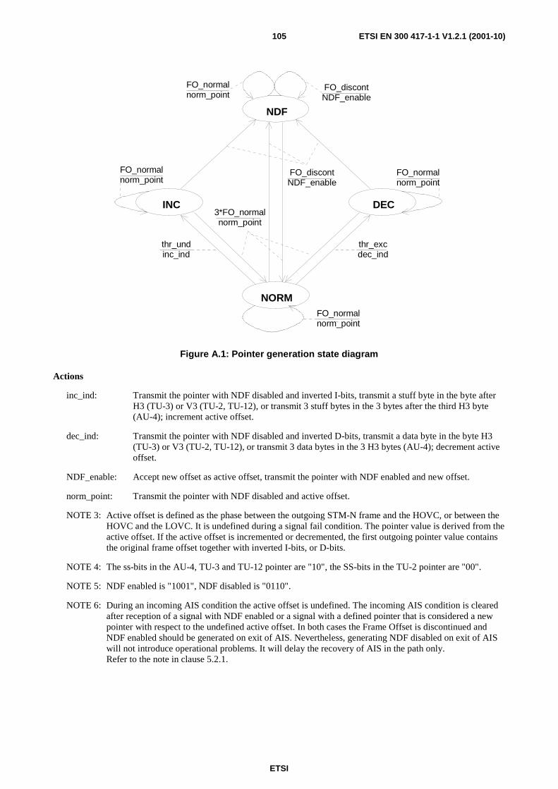
ETSI
ETSI EN 300 417-1-1 V1.2.1 (2001-10)105
INC DEC
NORM
NDF
thr_undinc_ind
thr_excdec_ind
3*FO_normalnorm_point
FO_discontNDF_enable
FO_normalnorm_point
FO_normalnorm_point
FO_normalnorm_point
FO_normalnorm_point
FO_discontNDF_enable
Figure A.1: Pointer generation state diagram
Actions
inc_ind: Transmit the pointer with NDF disabled and inverted I-bits, transmit a stuff byte in the byte after H3 (TU-3) or V3 (TU-2, TU-12), or transmit 3 stuff bytes in the 3 bytes after the third H3 byte (AU-4); increment active offset.
dec_ind: Transmit the pointer with NDF disabled and inverted D-bits, transmit a data byte in the byte H3 (TU-3) or V3 (TU-2, TU-12), or transmit 3 data bytes in the 3 H3 bytes (AU-4); decrement active offset.
NDF_enable: Accept new offset as active offset, transmit the pointer with NDF enabled and new offset.
norm_point: Transmit the pointer with NDF disabled and active offset.
NOTE 3: Active offset is defined as the phase between the outgoing STM-N frame and the HOVC, or between the HOVC and the LOVC. It is undefined during a signal fail condition. The pointer value is derived from the active offset. If the active offset is incremented or decremented, the first outgoing pointer value contains the original frame offset together with inverted I-bits, or D-bits.
NOTE 4: The ss-bits in the AU-4, TU-3 and TU-12 pointer are "10", the SS-bits in the TU-2 pointer are "00".
NOTE 5: NDF enabled is "1001", NDF disabled is "0110".
NOTE 6: During an incoming AIS condition the active offset is undefined. The incoming AIS condition is cleared after reception of a signal with NDF enabled or a signal with a defined pointer that is considered a new pointer with respect to the undefined active offset. In both cases the Frame Offset is discontinued and NDF enabled should be generated on exit of AIS. Nevertheless, generating NDF disabled on exit of AIS will not introduce operational problems. It will delay the recovery of AIS in the path only. Refer to the note in clause 5.2.1.

ETSI
ETSI EN 300 417-1-1 V1.2.1 (2001-10)106
Annex B (normative): Pointer interpretation The pointer interpretation algorithm can be globally described by a state diagram while the detailed specifications are better suited by a state table.
State diagram
Within the pointer interpretation algorithm six states are defined:
- NORMal_state (NORM);
- AIS_state (AIS);
- LOP_state (LOP);
- INCrement_state (INC);
- DECrement_state (DEC);
- NDF_state (NDF).
The transitions between the states will be initiated either by single events (inc, dec, ndf) or by a number of consecutive events (indications); e.g. three consecutive AIS indications to go from NORM_state to the AIS_state. The kind and number of consecutive indications activating a transition is chosen such that the behaviour is stable and insensitive to BER degradations.
It should be noted that non-consecutive invalid indications do not activate the transition to the LOP_state.
Events
The following state diagram events are defined:
For AU-4 and AU-4-Xc (X=4,16) pointers:
norm_point: disabled NDF (0110,1110,0010,0100,0111)
AND received pointer offset value equal to active offset value;
NDF_enable: NDF enabled (1001,0001,1101,1011,1000)
AND received pointer offset value in range;
AIS_ind: pointer = 11111111 11111111 (FFH FFH);
inc_ind: NDF disabled (0110,1110,0010,0100,0111)
AND majority of I-bits inverted
AND no majority of D-bits inverted;
dec_ind: NDF disabled (0110,1110,0010,0100,0111)
AND majority of D-bits inverted
AND no majority of I-bits inverted;
For TU-m (m=3,2,12,11) pointers:
norm_point: disabled NDF (0110,1110,0010,0100,0111)
AND match of ss-bits
AND received pointer offset value equal to active offset value;
ETSI
ETSI EN 300 417-1-1 V1.2.1 (2001-10)107
NDF_enable: NDF enabled (1001,0001,1101,1011,1000)
AND match of ss-bits
AND received pointer offset value in range;
AIS_ind: pointer = 11111111 11111111 (FFH FFH);
inc_ind: NDF disabled (0110,1110,0010,0100,0111)
AND match of ss-Bits
AND majority of I-bits inverted
AND no majority of D-bits inverted;
dec_ind: NDF disabled (0110,1110,0010,0100,0111)
AND match of ss-bits
AND majority of D-bits inverted
AND no majority of I-bits inverted;
For AU-4, AU-4-Xc and TU-m pointers:
inv_point: (Any other): NOT norm_point
AND NOT NDF_enable
AND NOT AIS_ind
AND NOT [(inc_ind OR dec_ind) AND NORM_state];
8*NDF_enable: eight consecutive NDF_enable;
3*AIS_ind: three consecutive AIS_ind;
8*inv_point: eight consecutive inv_point;
3*any_point: 3* NOT NDF_enable
AND NOT 3*AIS_ind
AND NOT 3*new_point.
One additional event (indication) has to be defined in order to restore normal operation in cases where, e.g. bit errors have corrupted the NDF bits during a NDF_enable condition (see note):
NOTE: One other condition requires this restore operation: a re-routing or protection switch action in an connection function which operates synchronously. In that case the adaptation source, with the elastic store and pointer generator, is located before the switching function and is unable to detect and react on the frame phase discontinuity caused by the switch action.
For AU-4, AU-4-Xc pointers:
new_point: disabled NDF (0110,1110,0010,0100,0111)
AND received pointer offset value in range but not equal to active offset value
For TU-m pointers:
new_point: disabled NDF (0110,1110,0010,0100,0111)
AND match of ss-bits
AND received pointer offset value in range but not equal to active offset value
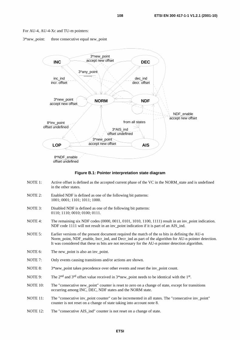
ETSI
ETSI EN 300 417-1-1 V1.2.1 (2001-10)108
For AU-4, AU-4-Xc and TU-m pointers:
3*new_point: three consecutive equal new_point
INC DEC
NORM NDF
AISLOP
3*new_pointaccept new offset
3*any_point-------
3*AIS_indoffset undefined
8*NDF_enableoffset undefined
NDF_enableaccept new offset
dec_inddecr. offset
inc_indincr. offset
from all states8*inv_pointoffset undefined
3*new_pointaccept new offset
3*new_pointaccept new offset
Figure B.1: Pointer interpretation state diagram
NOTE 1: Active offset is defined as the accepted current phase of the VC in the NORM_state and is undefined in the other states.
NOTE 2: Enabled NDF is defined as one of the following bit patterns: 1001; 0001; 1101; 1011; 1000.
NOTE 3: Disabled NDF is defined as one of the following bit patterns: 0110; 1110; 0010; 0100; 0111.
NOTE 4: The remaining six NDF codes (0000, 0011, 0101, 1010, 1100, 1111) result in an inv_point indication. NDF code 1111 will not result in an inv_point indication if it is part of an AIS_ind.
NOTE 5: Earlier versions of the present document required the match of the ss bits in defining the AU-n Norm_point, NDF_enable, Incr_ind, and Decr_ind as part of the algorithm for AU-n pointer detection. It was considered that these ss bits are not necessary for the AU-n pointer detection algorithm.
NOTE 6: The new_point is also an inv_point.
NOTE 7: Only events causing transitions and/or actions are shown.
NOTE 8: 3*new_point takes precedence over other events and reset the inv_point count.
NOTE 9: The 2nd and 3rd offset value received in 3*new_point needs to be identical with the 1st.
NOTE 10: The "consecutive new_point" counter is reset to zero on a change of state, except for transitions occurring among INC, DEC, NDF states and the NORM state.
NOTE 11: The "consecutive inv_point counter" can be incremented in all states. The "consecutive inv_point" counter is not reset on a change of state taking into account note 8.
NOTE 12: The "consecutive AIS_ind" counter is not reset on a change of state.

ETSI
ETSI EN 300 417-1-1 V1.2.1 (2001-10)109
NOTE 13: The "consecutive NDF_enable" counter is reset to zero on a change of AIS to NDF state; otherwise the counter is not reset.
NOTE 14: A persistent mismatch between provisioned and received AU and TU types will result in a LOP defect. The TU-12, TU-2 and TU-3 structures are differentiated in the PI process by their ss-bits values. The AU-3 and AU-4 structures have identical ss-bits values. Differentiation can be obtained by checking the Y bytes at locations (4,2,c) and (4,3,c).
State table
The following State Table events are defined:
For AU-4, AU-4-Xc pointers:
- norm_point: disabled_NDF && pointer_offset_equal_to_active_offset
- NDF_enable: enabled_NDF && pointer_offset_in_range
- AIS_ind: 11111111_11111111
- inc_ind: disabled_NDF && majority_of_I_bits_inverted && no_majority_of_D_bits_inverted
- dec_ind: disabled_NDF && majority_of_D_bits_inverted && no_majority_of_I_bits_inverted
- inv_point: any_other (i.e. !norm_point && !NDF_enable && !AIS_ind && !inc_ind && !dec_ind)
For TU-m pointers:
- norm_point: disabled_NDF && match_of_ss_bits && pointer_offset_equal_to_active_offset
- NDF_enable: enabled_NDF && match_of_ss_bits && pointer_offset_in_range
- AIS_ind: 11111111_11111111
- inc_ind: disabled_NDF && match_of_ss_bits && majority_of_I_bits_inverted && no_majority_of_D_bits_inverted
- dec_ind: disabled_NDF && match_of_ss_bits && majority_of_D_bits_inverted && no_majority_of_I_bits_inverted
- inv_point: any_other (i.e. !norm_point && !NDF_enable && !AIS_ind && !inc_ind && !dec_ind)
NOTE 14a: 3xeq_new_point can not occur before one of the following three sequences:
1) inv_point - inv_point - inv_point,
2) inc_ind - inv_point - inv_point,
3) dec_ind - inv_point - inv_point.
NOTE 14b: 3xeq_new_point takes precedence over other events.
NOTE 14c: n.a.: not applicable.
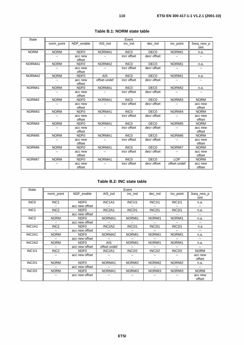
ETSI
ETSI EN 300 417-1-1 V1.2.1 (2001-10)110
Table B.1: NORM state table
State Event norm_point NDF_enable AIS_ind inc_ind dec_ind inv_point 3xeq_new_p
oint NORM NORM NDF0 NORMA1 INC0 DEC0 NORMI1 n.a.
-- acc new offset
-- incr offset decr offset -- --
NORMA1 NORM NDF0 NORMA2 INC0 DEC0 NORMI1 n.a. -- acc new
offset -- incr offset decr offset -- --
NORMA2 NORM NDF0 AIS INC0 DEC0 NORMI1 n.a. -- acc new
offset offset undef incr offset decr offset -- --
NORMI1 NORM NDF0 NORMA1 INC0 DEC0 NORMI2 n.a. -- acc new
offset -- incr offset decr offset -- --
NORMI2 NORM NDF0 NORMA1 INC0 DEC0 NORMI3 NORM -- acc new
offset -- incr offset decr offset -- acc new
offset NORMI3 NORM NDF0 NORMA1 INC0 DEC0 NORMI4 NORM
-- acc new offset
-- incr offset decr offset -- acc new offset
NORMI4 NORM NDF0 NORMA1 INC0 DEC0 NORMI5 NORM -- acc new
offset -- incr offset decr offset -- acc new
offset NORMI5 NORM NDF0 NORMA1 INC0 DEC0 NORMI6 NORM
-- acc new offset
-- incr offset decr offset -- acc new offset
NORMI6 NORM NDF0 NORMA1 INC0 DEC0 NORMI7 NORM -- acc new
offset -- incr offset decr offset -- acc new
offset NORMI7 NORM NDF0 NORMA1 INC0 DEC0 LOP NORM
-- acc new offset
-- incr offset decr offset offset undef acc new offset
Table B.2: INC state table
State Event norm_point NDF_enable AIS_ind inc_ind dec_ind inv_point 3xeq_new_p
oint INC0 INC1 NDF0 INC1A1 INC1I1 INC1I1 INC1I1 n.a.
-- acc new offset -- -- -- -- -- INC1 INC2 NDF0 INC2A1 INC2I1 INC2I1 INC2I1 n.a.
-- acc new offset -- -- -- -- -- INC2 NORM NDF0 NORMA1 NORMI1 NORMI1 NORMI1 n.a.
-- acc new offset -- -- -- -- -- INC1A1 INC2 NDF0 INC2A2 INC2I1 INC2I1 INC2I1 n.a
-- acc new offset -- -- -- -- -- INC2A1 NORM NDF0 NORMA2 NORMI1 NORMI1 NORMI1 n.a.
-- acc new offset -- -- -- -- -- INC2A2 NORM NDF0 AIS NORMI1 NORMI1 NORMI1 n.a.
-- acc new offset offset undef -- -- -- -- INC1I1 INC2 NDF0 INC2A1 INC2I2 INC2I2 INC2I2 NORM
-- acc new offset -- -- -- -- acc new offset
INC2I1 NORM NDF0 NORMA1 NORMI2 NORMI2 NORMI2 n.a. -- acc new offset -- -- -- -- --
INC2I2 NORM NDF0 NORMA1 NORMI3 NORMI3 NORMI3 NORM -- acc new offset -- -- -- -- acc new
offset

ETSI
ETSI EN 300 417-1-1 V1.2.1 (2001-10)111
Table B.3: DEC state table
State Event norm_point NDF_enable AIS_ind inc_ind dec_ind inv_point 3xeq_new_p
oint DEC0 DEC1 NDF0 DEC1A1 DEC1I1 DEC1I1 DEC1I1 n.a.
-- acc new offset
-- -- -- -- --
DEC1 DEC2 NDF0 DEC2A1 DEC2I1 DEC2I1 DEC2I1 n.a. -- acc new
offset -- -- -- -- --
DEC2 NORM NDF0 NORMA1 NORMI1 NORMI1 NORMI1 n.a. -- acc new
offset -- -- -- -- --
DEC1A1 DEC2 NDF0 DEC2A2 DEC2I1 DEC2I1 DEC2I1 n.a. -- acc new
offset -- -- -- -- --
DEC2A1 NORM NDF0 NORMA2 NORMI1 NORMI1 NORMI1 n.a. -- acc new
offset -- -- -- -- --
DEC2A2 NORM NDF0 AIS NORMI1 NORMI1 NORMI1 n.a. -- acc new
offset offset undef -- -- -- --
DEC1I1 DEC2 NDF0 DEC2A1 DEC2I2 DEC2I2 DEC2I2 NORM -- acc new
offset -- -- -- -- acc new
offset DEC2I1 NORM NDF0 NORMA1 NORMI2 NORMI2 NORMI2 n.a.
-- acc new offset
-- -- -- -- --
DEC2I2 NORM NDF0 NORMA1 NORMI3 NORMI3 NORMI3 NORM -- acc new
offset -- -- -- -- acc new
offset
Table B.4: AIS state table
State Event norm_point NDF_enable AIS_ind inc_ind dec_ind inv_point 3xeq_new_p
oint AIS n.a. NDF AIS n.a. n.a. AISI1 n.a.
-- acc new offset
-- -- -- -- --
AISI1 n.a. NDF AIS n.a. n.a. AISI2 n.a. -- acc new
offset -- -- -- -- --
AISI2 n.a. NDF AIS n.a. n.a. AISI3 NORM -- acc new
offset -- -- -- -- acc new
offset AISI3 n.a. NDF AIS n.a. n.a. AISI4 NORM
-- acc new offset
-- -- -- -- acc new offset
AISI4 n.a. NDF AIS n.a. n.a. AISI5 NORM -- acc new
offset -- -- -- -- acc new
offset AISI5 n.a. NDF AIS n.a. n.a. AISI6 NORM
-- acc new offset
-- -- -- -- acc new offset
AISI6 n.a. NDF AIS n.a. n.a. AISI7 NORM -- acc new
offset -- -- -- -- acc new
offset AISI7 n.a. NDF AIS n.a. n.a. LOP NORM
-- acc new offset
-- -- -- offset undef acc new offset
NOTE 14d: With the offset being undefined in the AIS state norm_point, inc_ind and dec_ind are not defined.

ETSI
ETSI EN 300 417-1-1 V1.2.1 (2001-10)112
Table B.5: LOP state table
State Event norm_point NDF_enable AIS_ind inc_ind dec_ind inv_point 3xeq_new_p
oint LOP n.a. LOP LOPA1 n.a. n.a. LOP NORM
-- -- -- -- -- -- acc new offset
LOPA1 n.a. LOP LOPA2 n.a. n.a. LOP n.a. -- -- -- -- -- -- --
LOPA2 n.a. LOP AIS n.a. n.a. LOP n.a. -- -- -- -- -- -- --
NOTE 14e: With the offset being undefined in the AIS state norm_point, inc_ind and dec_ind are not defined.
Table B.6: NDF state table
State Event norm_point NDF_enable AIS_ind inc_ind dec_ind inv_point 3xeq_new_p
oint NDF NDF1 NDFN0 NDF1A1 NDF1I1 NDF1I1 NDF1I1 n.a.
-- acc new offset
-- -- -- -- --
NDF0 NDF1 NDFN2 NDF1A1 NDF1I1 NDF1I1 NDF1I1 n.a. -- acc new
offset -- -- -- -- --
NDF1 NDF2 NDF0 NDF2A1 NDF2I1 NDF2I1 NDF2I1 n.a. -- acc new
offset -- -- -- -- --
NDF2 NORM NDF0 NORMA1 NORMI1 NORMI1 NORMI1 n.a. -- acc new
offset -- -- -- -- --
NDF1A1 NDF2 NDF0 NDF2A2 NDF2I1 NDF2I1 NDF2I1 n.a. -- acc new
offset -- -- -- -- --
NDF2A1 NORM NDF0 NORMA2 NORMI1 NORMI1 NORMI1 n.a. -- acc new
offset -- -- -- -- --
NDF2A2 NORM NDF0 AIS NORMI1 NORMI1 NORMI1 n.a. -- acc new
offset offset undef -- -- -- --
NDF1I1 NDF2 NDF0 NDF2A1 NDF2I2 NDF2I2 NDF2I2 n.a. -- acc new
offset -- -- -- -- --
NDF2I1 NORM NDF0 NORMA1 NORMI2 NORMI2 NORMI2 n.a. -- acc new
offset -- -- -- -- --
NDF2I2 NORM NDF0 NORMA1 NORMI3 NORMI3 NORMI3 NORM -- acc new
offset -- -- -- -- acc new
offset NDFN2 NDF1 NDFN3 NDF1A1 NDF1I1 NDF1I1 NDF1I1 n.a.
-- acc new offset
-- -- -- -- --
NDFN3 NDF1 NDFN4 NDF1A1 NDF1I1 NDF1I1 NDF1I1 n.a. -- acc new
offset -- -- -- -- --
NDFN4 NDF1 NDFN5 NDF1A1 NDF1I1 NDF1I1 NDF1I1 n.a. -- acc new
offset -- -- -- -- --
NDFN5 NDF1 NDFN6 NDF1A1 NDF1I1 NDF1I1 NDF1I1 n.a. -- acc new
offset -- -- -- -- --
NDFN6 NDF1 NDFN7 NDF1A1 NDF1I1 NDF1I1 NDF1I1 n.a. -- acc new
offset -- -- -- -- --
NDFN7 NDF1 LOP NDF1A1 NDF1I1 NDF1I1 NDF1I1 n.a. -- offset undef -- -- -- -- --

ETSI
ETSI EN 300 417-1-1 V1.2.1 (2001-10)113
Table B.7: CONC state table
State Event conc_point AIS_ind inv_point
CONC CONC CONCA1 CONCI1 -- -- --
CONCA1 CONC CONCA2 CONCI1 -- -- --
CONCA2 CONC AISC CONCI1 -- -- --
CONCI1 CONC CONCA1 CONCI2 -- -- --
CONCI2 CONC CONCA1 CONCI3 -- -- --
CONCI3 CONC CONCA1 CONCI4 -- -- --
CONCI4 CONC CONCA1 CONCI5 -- -- --
CONCI5 CONC CONCA1 CONCI6 -- -- --
CONCI6 CONC CONCA1 CONCI7 -- -- --
CONCI7 CONC CONCA1 LOPC -- -- --
Table B.8: AISC state table
State Event conc_point AIS_ind inv_point
AISC AISCC1 AISC AISCI1 -- -- --
AISCC1 AISCC2 AISC AISCI1 -- -- --
AISCC2 CONC AISC AISCI1 -- -- --
AISCI1 AISCC1 AISC AISCI2 -- -- --
AISCI2 AISCC1 AISC AISCI3 -- -- --
AISCI3 AISCC1 AISC AISCI4 -- -- --
AISCI4 AISCC1 AISC AISCI5 -- -- --
AISCI5 AISCC1 AISC AISCI6 -- -- --
AISCI6 AISCC1 AISC AISCI7 -- -- --
AISCI7 AISCC1 AISC LOPC -- -- --
Table B.9: LOPC state table
State Event conc_point AIS_ind inv_point
LOPC LOPCC1 LOPCA1 LOPC -- -- --
LOPCC1 LOPCC2 LOPCA1 LOPC -- -- --
LOPCC2 CONC LOPCA1 LOPC -- -- --
LOPCA1 LOPCC1 LOPCA2 LOPC -- -- --
LOPCA2 LOPCC1 AISC LOPC -- -- --
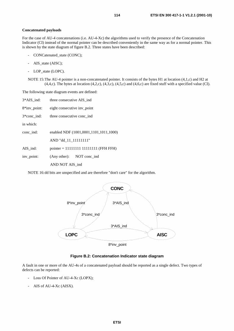
ETSI
ETSI EN 300 417-1-1 V1.2.1 (2001-10)114
Concatenated payloads
For the case of AU-4 concatenations (i.e. AU-4-Xc) the algorithms used to verify the presence of the Concatenation Indicator (CI) instead of the normal pointer can be described conveniently in the same way as for a normal pointer. This is shown by the state diagram of figure B.2. Three states have been described:
- CONCatenated_state (CONC);
- AIS_state (AISC);
- LOP_state (LOPC).
NOTE 15: The AU-4 pointer is a non-concatenated pointer. It consists of the bytes H1 at location (4,1,c) and H2 at (4,4,c). The bytes at location (4,2,c), (4,3,c), (4,5,c) and (4,6,c) are fixed stuff with a specified value (CI).
The following state diagram events are defined:
3*AIS_ind: three consecutive AIS_ind
8*inv_point: eight consecutive inv_point
3*conc_ind: three consecutive conc_ind
in which:
conc_ind: enabled NDF (1001,0001,1101,1011,1000)
AND "dd_11_11111111"
AIS_ind: pointer = 11111111 11111111 (FFH FFH)
inv_point: (Any other): NOT conc_ind
AND NOT AIS_ind
NOTE 16: dd bits are unspecified and are therefore "don't care" for the algorithm.
CONC
AISCLOPC
3*conc_ind
8*inv_point 3*AIS_ind
3*conc_ind
8*inv_point
3*AIS_ind
Figure B.2: Concatenation Indicator state diagram
A fault in one or more of the AU-4s of a concatenated payload should be reported as a single defect. Two types of defects can be reported:
- Loss Of Pointer of AU-4-Xc (LOPX);
- AIS of AU-4-Xc (AISX).

ETSI
ETSI EN 300 417-1-1 V1.2.1 (2001-10)115
They are defined as follows:
AISX: AIS#1 AND AISC#2 AND... AND AISC#X
NORMX: NORM#1 AND CONC#2 AND... AND CONC#X
INCX: INC#1 AND CONC#2 AND... AND CONC#X
DECX: DEC#1 AND CONC#2 AND... AND CONC#X
NDFX: NDF#1 AND CONC#2 AND... AND CONC#X
LOPX: (Any other): NOT AISX
AND NOT NORMX
AND NOT INCX
AND NOT DECX
AND NOT NDFX
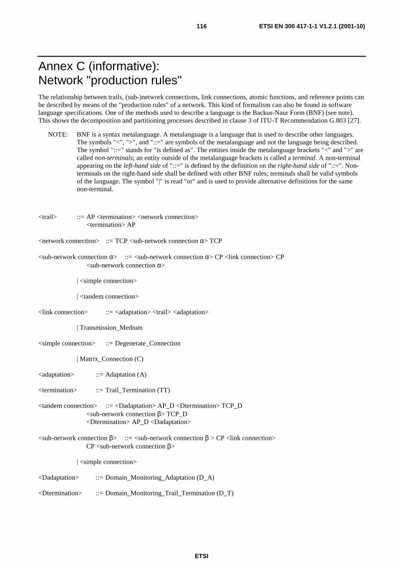
ETSI
ETSI EN 300 417-1-1 V1.2.1 (2001-10)116
Annex C (informative): Network "production rules" The relationship between trails, (sub-)network connections, link connections, atomic functions, and reference points can be described by means of the "production rules" of a network. This kind of formalism can also be found in software language specifications. One of the methods used to describe a language is the Backus-Naur Form (BNF) (see note). This shows the decomposition and partitioning processes described in clause 3 of ITU-T Recommendation G.803 [27].
NOTE: BNF is a syntax metalanguage. A metalanguage is a language that is used to describe other languages. The symbols "<", ">", and "::=" are symbols of the metalanguage and not the language being described. The symbol "::=" stands for "is defined as". The entities inside the metalanguage brackets "<" and ">" are called non-terminals; an entity outside of the metalanguage brackets is called a terminal. A non-terminal appearing on the left-hand side of "::=" is defined by the definition on the right-hand side of "::=". Non-terminals on the right-hand side shall be defined with other BNF rules; terminals shall be valid symbols of the language. The symbol "|" is read "or" and is used to provide alternative definitions for the same non-terminal.
<trail> ::= AP <termination> <network connection> <termination> AP <network connection> ::= TCP <sub-network connection α> TCP <sub-network connection α> ::= <sub-network connection α> CP <link connection> CP <sub-network connection α> | <simple connection> | <tandem connection> <link connection> ::= <adaptation> <trail> <adaptation> | Transmission_Medium <simple connection> ::= Degenerate_Connection | Matrix_Connection (C) <adaptation> ::= Adaptation (A) <termination> ::= Trail_Termination (TT) <tandem connection> ::= <Dadaptation> AP_D <Dtermination> TCP_D <sub-network connection β> TCP_D <Dtermination> AP_D <Dadaptation> <sub-network connection β> ::= <sub-network connection β > CP <link connection> CP <sub-network connection β> | <simple connection> <Dadaptation> ::= Domain_Monitoring_Adaptation (D_A) <Dtermination> ::= Domain_Monitoring_Trail_Termination (D_T)

ETSI
ETSI EN 300 417-1-1 V1.2.1 (2001-10)117
AP_D: Domain Monitoring Access Point CP_D: Domain monitoring Connection Point TCP_D: Domain Monitoring Termination Connection Point TM: Transmission_Medium The <sub-network connection> shows the recursion, which terminates when the <simple connection> is selected. This <simple connection> represents the cross-connection on an individual matrix, or an inflexible (fixed) connection for the case where a matrix is not present. It is represented by the (flexible) connection function or an (inflexible) line.
The <link connection> shows the layering process, which terminates when the Transmission_Medium is selected.
The concept of the <tandem connection> is introduced here because it is considered to provide a rigid way of describing the property that is required for the so-called tandem connection i.e. a sub-network connection that can be monitored via an overhead dedicated for this purpose.
The addition of a rigid set of syntax rules is for further study.
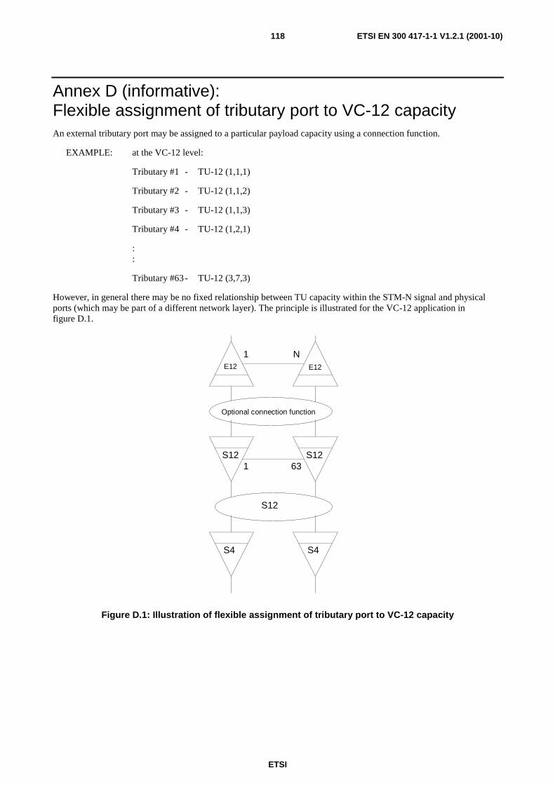
ETSI
ETSI EN 300 417-1-1 V1.2.1 (2001-10)118
Annex D (informative): Flexible assignment of tributary port to VC-12 capacity An external tributary port may be assigned to a particular payload capacity using a connection function.
EXAMPLE: at the VC-12 level:
Tributary #1 - TU-12 (1,1,1)
Tributary #2 - TU-12 (1,1,2)
Tributary #3 - TU-12 (1,1,3)
Tributary #4 - TU-12 (1,2,1)
: :
Tributary #63 - TU-12 (3,7,3)
However, in general there may be no fixed relationship between TU capacity within the STM-N signal and physical ports (which may be part of a different network layer). The principle is illustrated for the VC-12 application in figure D.1.
1 NE12
S121 63
Optional connection function
S4
E12
S12
S4
S12
Figure D.1: Illustration of flexible assignment of tributary port to VC-12 capacity
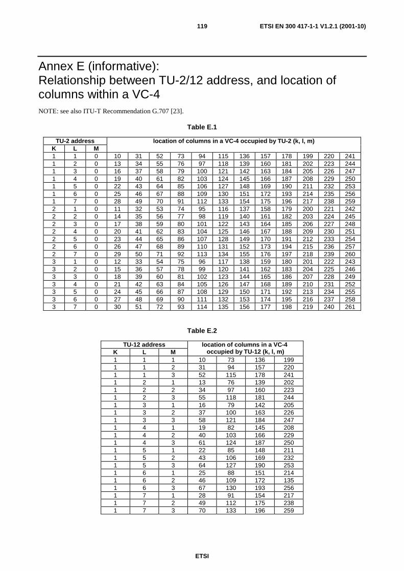
ETSI
ETSI EN 300 417-1-1 V1.2.1 (2001-10)119
Annex E (informative): Relationship between TU-2/12 address, and location of columns within a VC-4 NOTE: see also ITU-T Recommendation G.707 [23].
Table E.1
TU-2 address K L M
location of columns in a VC-4 occupied by TU-2 (k, l, m)
1 1 0 10 31 52 73 94 115 136 157 178 199 220 241 1 2 0 13 34 55 76 97 118 139 160 181 202 223 244 1 3 0 16 37 58 79 100 121 142 163 184 205 226 247 1 4 0 19 40 61 82 103 124 145 166 187 208 229 250 1 5 0 22 43 64 85 106 127 148 169 190 211 232 253 1 6 0 25 46 67 88 109 130 151 172 193 214 235 256 1 7 0 28 49 70 91 112 133 154 175 196 217 238 259 2 1 0 11 32 53 74 95 116 137 158 179 200 221 242 2 2 0 14 35 56 77 98 119 140 161 182 203 224 245 2 3 0 17 38 59 80 101 122 143 164 185 206 227 248 2 4 0 20 41 62 83 104 125 146 167 188 209 230 251 2 5 0 23 44 65 86 107 128 149 170 191 212 233 254 2 6 0 26 47 68 89 110 131 152 173 194 215 236 257 2 7 0 29 50 71 92 113 134 155 176 197 218 239 260 3 1 0 12 33 54 75 96 117 138 159 180 201 222 243 3 2 0 15 36 57 78 99 120 141 162 183 204 225 246 3 3 0 18 39 60 81 102 123 144 165 186 207 228 249 3 4 0 21 42 63 84 105 126 147 168 189 210 231 252 3 5 0 24 45 66 87 108 129 150 171 192 213 234 255 3 6 0 27 48 69 90 111 132 153 174 195 216 237 258 3 7 0 30 51 72 93 114 135 156 177 198 219 240 261
Table E.2
TU-12 address K L M
location of columns in a VC-4 occupied by TU-12 (k, l, m)
1 1 1 10 73 136 199 1 1 2 31 94 157 220 1 1 3 52 115 178 241 1 2 1 13 76 139 202 1 2 2 34 97 160 223 1 2 3 55 118 181 244 1 3 1 16 79 142 205 1 3 2 37 100 163 226 1 3 3 58 121 184 247 1 4 1 19 82 145 208 1 4 2 40 103 166 229 1 4 3 61 124 187 250 1 5 1 22 85 148 211 1 5 2 43 106 169 232 1 5 3 64 127 190 253 1 6 1 25 88 151 214 1 6 2 46 109 172 135 1 6 3 67 130 193 256 1 7 1 28 91 154 217 1 7 2 49 112 175 238 1 7 3 70 133 196 259
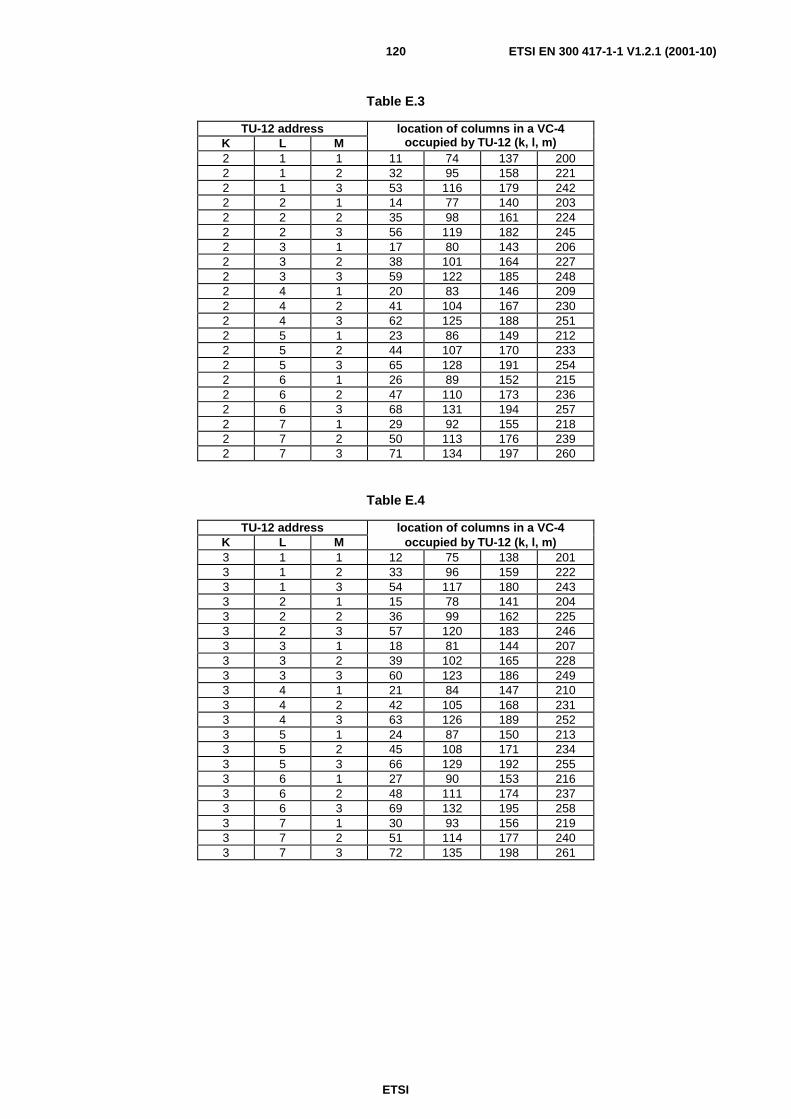
ETSI
ETSI EN 300 417-1-1 V1.2.1 (2001-10)120
Table E.3
TU-12 address K L M
location of columns in a VC-4 occupied by TU-12 (k, l, m)
2 1 1 11 74 137 200 2 1 2 32 95 158 221 2 1 3 53 116 179 242 2 2 1 14 77 140 203 2 2 2 35 98 161 224 2 2 3 56 119 182 245 2 3 1 17 80 143 206 2 3 2 38 101 164 227 2 3 3 59 122 185 248 2 4 1 20 83 146 209 2 4 2 41 104 167 230 2 4 3 62 125 188 251 2 5 1 23 86 149 212 2 5 2 44 107 170 233 2 5 3 65 128 191 254 2 6 1 26 89 152 215 2 6 2 47 110 173 236 2 6 3 68 131 194 257 2 7 1 29 92 155 218 2 7 2 50 113 176 239 2 7 3 71 134 197 260
Table E.4
TU-12 address location of columns in a VC-4 K L M occupied by TU-12 (k, l, m) 3 1 1 12 75 138 201 3 1 2 33 96 159 222 3 1 3 54 117 180 243 3 2 1 15 78 141 204 3 2 2 36 99 162 225 3 2 3 57 120 183 246 3 3 1 18 81 144 207 3 3 2 39 102 165 228 3 3 3 60 123 186 249 3 4 1 21 84 147 210 3 4 2 42 105 168 231 3 4 3 63 126 189 252 3 5 1 24 87 150 213 3 5 2 45 108 171 234 3 5 3 66 129 192 255 3 6 1 27 90 153 216 3 6 2 48 111 174 237 3 6 3 69 132 195 258 3 7 1 30 93 156 219 3 7 2 51 114 177 240 3 7 3 72 135 198 261
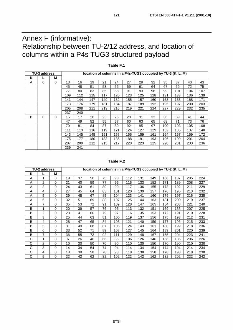
ETSI
ETSI EN 300 417-1-1 V1.2.1 (2001-10)121
Annex F (informative): Relationship between TU-2/12 address, and location of columns within a P4s TUG3 structured payload
Table F.1
TU-3 address K L M
location of columns in a P4s-TUG3 occupied by TU-3 (K, L, M)
A 0 0 13 16 19 21 24 27 29 32 35 37 40 43 45 48 51 53 56 59 61 64 67 69 72 75 77 80 83 85 88 91 93 96 99 101 104 107 109 112 115 117 120 123 125 128 131 133 136 139 141 144 147 149 152 155 157 160 163 165 168 171 173 176 179 181 184 187 189 192 195 197 200 203 205 208 211 213 216 219 221 224 227 229 232 235 237 240
B 0 0 15 17 20 23 25 28 31 33 36 39 41 44 47 49 52 55 57 60 63 65 68 71 73 76 79 81 84 87 89 92 95 97 100 103 105 108 111 113 116 119 121 124 127 129 132 135 137 140 143 145 148 151 153 156 159 161 164 167 169 172 175 177 180 183 185 188 191 193 196 199 201 204 207 209 212 215 217 220 223 225 228 231 233 236 239 241
Table F.2
TU-2 address K L M
location of columns in a P4s-TUG3 occupied by TU-2 (K, L, M)
A 1 0 19 37 56 75 93 112 131 149 168 187 205 224 A 2 0 21 40 59 77 96 115 133 152 171 189 208 227 A 3 0 24 43 61 80 99 117 136 155 173 192 211 229 A 4 0 27 45 64 83 101 120 139 157 176 195 213 232 A 5 0 29 48 67 85 104 123 141 160 179 197 216 235 A 6 0 32 51 69 88 107 125 144 163 181 200 219 237 A 7 0 35 53 72 91 109 128 147 165 184 203 221 240 B 1 0 20 39 57 76 95 113 132 151 169 188 207 225 B 2 0 23 41 60 79 97 116 135 153 172 191 210 228 B 3 0 25 44 63 81 100 119 137 156 175 193 212 231 B 4 0 28 47 65 84 103 121 140 159 177 196 215 233 B 5 0 31 49 68 87 105 124 143 161 180 199 218 236 B 6 0 33 52 71 89 108 127 145 164 183 201 220 239 B 7 0 36 55 73 92 111 129 148 167 185 204 223 241 C 1 0 6 26 46 66 86 106 126 146 166 186 206 226 C 2 0 10 30 50 70 90 110 130 150 170 190 210 230 C 3 0 14 34 54 74 94 114 134 154 174 194 214 234 C 4 0 18 38 58 78 98 118 138 158 178 198 218 238 C 5 0 22 42 62 82 102 122 142 162 182 202 222 242
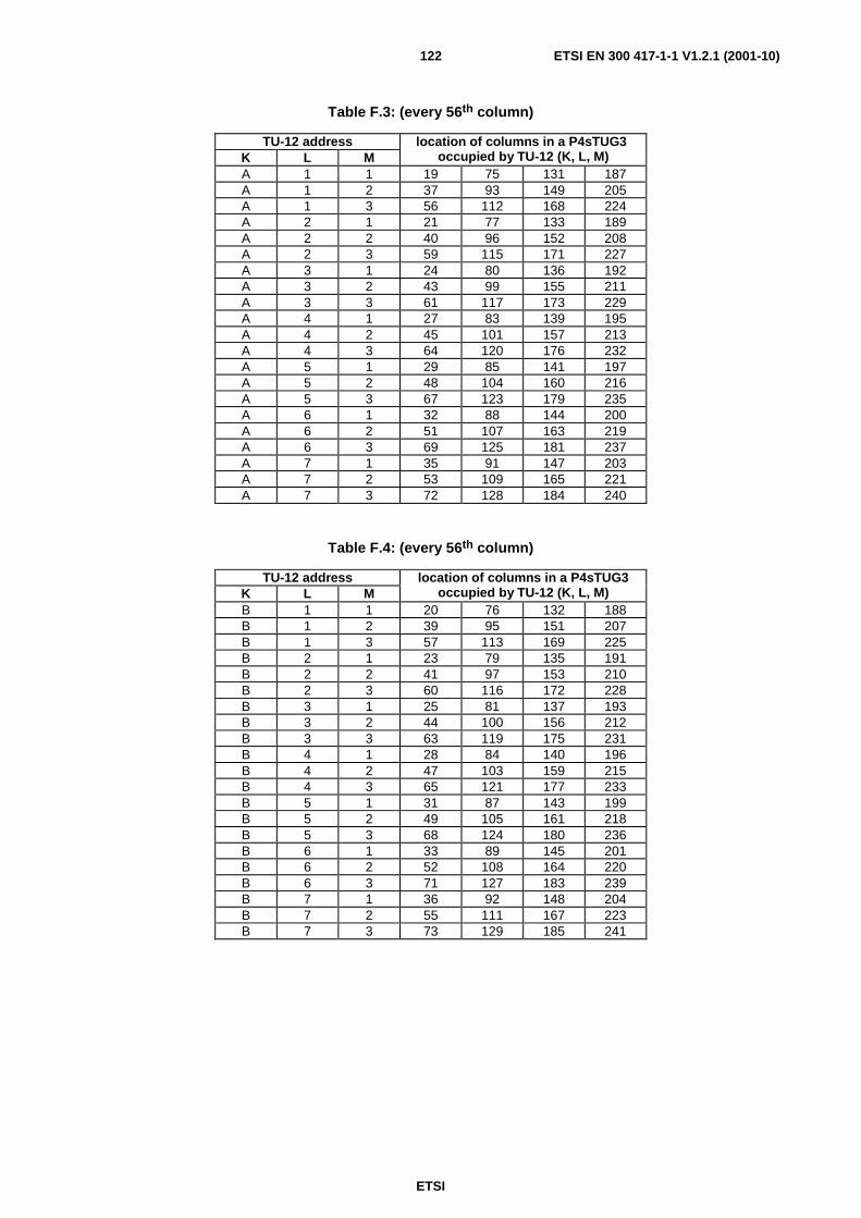
ETSI
ETSI EN 300 417-1-1 V1.2.1 (2001-10)122
Table F.3: (every 56th column)
TU-12 address K L M
location of columns in a P4sTUG3 occupied by TU-12 (K, L, M)
A 1 1 19 75 131 187 A 1 2 37 93 149 205 A 1 3 56 112 168 224 A 2 1 21 77 133 189 A 2 2 40 96 152 208 A 2 3 59 115 171 227 A 3 1 24 80 136 192 A 3 2 43 99 155 211 A 3 3 61 117 173 229 A 4 1 27 83 139 195 A 4 2 45 101 157 213 A 4 3 64 120 176 232 A 5 1 29 85 141 197 A 5 2 48 104 160 216 A 5 3 67 123 179 235 A 6 1 32 88 144 200 A 6 2 51 107 163 219 A 6 3 69 125 181 237 A 7 1 35 91 147 203 A 7 2 53 109 165 221 A 7 3 72 128 184 240
Table F.4: (every 56th column)
TU-12 address K L M
location of columns in a P4sTUG3 occupied by TU-12 (K, L, M)
B 1 1 20 76 132 188 B 1 2 39 95 151 207 B 1 3 57 113 169 225 B 2 1 23 79 135 191 B 2 2 41 97 153 210 B 2 3 60 116 172 228 B 3 1 25 81 137 193 B 3 2 44 100 156 212 B 3 3 63 119 175 231 B 4 1 28 84 140 196 B 4 2 47 103 159 215 B 4 3 65 121 177 233 B 5 1 31 87 143 199 B 5 2 49 105 161 218 B 5 3 68 124 180 236 B 6 1 33 89 145 201 B 6 2 52 108 164 220 B 6 3 71 127 183 239 B 7 1 36 92 148 204 B 7 2 55 111 167 223 B 7 3 73 129 185 241

ETSI
ETSI EN 300 417-1-1 V1.2.1 (2001-10)123
Table F.5: (every 60th column)
TU-12 address K L M
location of columns in a P4sTUG3 occupied by TU-12 (K, L, M)
C 1 1 6 66 126 186 C 1 2 26 86 146 206 C 1 3 46 106 166 226 C 2 1 10 70 130 190 C 2 2 30 90 150 210 C 2 3 50 110 170 230 C 3 1 14 74 134 194 C 3 2 34 94 154 214 C 3 3 54 114 174 234 C 4 1 18 78 138 198 C 4 2 38 98 158 218 C 4 3 58 118 178 238 C 5 1 22 82 142 202 C 5 2 42 102 162 222 C 5 3 62 122 182 242
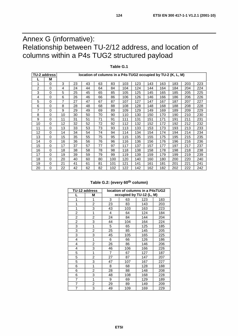
ETSI
ETSI EN 300 417-1-1 V1.2.1 (2001-10)124
Annex G (informative): Relationship between TU-2/12 address, and location of columns within a P4s TUG2 structured payload
Table G.1
TU-2 address L M
location of columns in a P4s-TUG2 occupied by TU-2 (K, L, M)
1 0 3 23 43 63 83 103 123 143 163 183 203 223 2 0 4 24 44 64 84 104 124 144 164 184 204 224 3 0 5 25 45 65 85 105 125 145 165 185 205 225 4 0 6 26 46 66 86 106 126 146 166 186 206 226 5 0 7 27 47 67 87 107 127 147 167 187 207 227 6 0 8 28 48 68 88 108 128 148 168 188 208 228 7 0 9 29 49 69 89 109 129 149 169 189 209 229 8 0 10 30 50 70 90 110 130 150 170 190 210 230 9 0 11 31 51 71 91 111 131 151 171 191 211 231
10 0 12 32 52 72 92 112 132 152 172 192 212 232 11 0 13 33 53 73 93 113 133 153 173 193 213 233 12 0 14 34 54 74 94 114 134 154 174 194 214 234 13 0 15 35 55 75 95 115 135 155 175 195 215 235 14 0 16 36 56 76 96 116 136 156 176 196 216 236 15 0 17 37 57 77 97 117 137 157 177 197 217 237 16 0 18 38 58 78 98 118 138 158 178 198 218 238 17 0 19 39 59 79 99 119 139 159 179 199 219 239 18 0 20 40 60 80 100 120 140 160 180 200 220 240 19 0 21 41 61 81 101 121 141 161 181 201 221 241 20 0 22 42 62 82 102 122 142 162 182 202 222 242
Table G.2: (every 60th column)
TU-12 address L M
location of columns in a P4sTUG2 occupied by TU-12 (L, M)
1 1 3 63 123 183 1 2 23 83 143 203 1 3 43 103 163 223 2 1 4 64 124 184 2 2 24 84 144 204 2 3 44 104 164 224 3 1 5 65 125 185 3 2 25 85 145 205 3 3 45 105 165 225 4 1 6 66 126 186 4 2 26 86 146 206 4 3 46 106 166 226 5 1 7 67 127 187 5 2 27 87 147 207 5 3 47 107 167 227 6 1 8 68 128 188 6 2 28 88 148 208 6 3 48 108 168 228 7 1 9 69 129 189 7 2 29 89 149 209 7 3 49 109 169 229
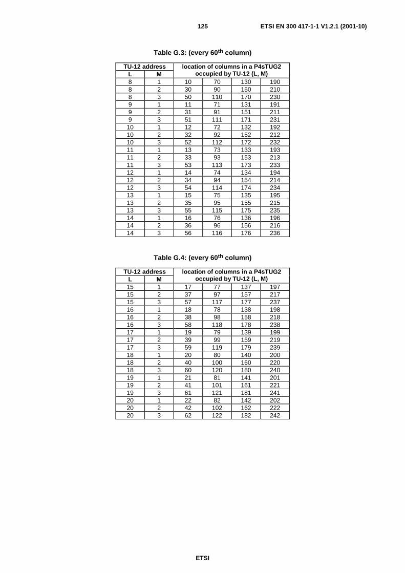
ETSI
ETSI EN 300 417-1-1 V1.2.1 (2001-10)125
Table G.3: (every 60th column)
TU-12 address L M
location of columns in a P4sTUG2 occupied by TU-12 (L, M)
8 1 10 70 130 190 8 2 30 90 150 210 8 3 50 110 170 230 9 1 11 71 131 191 9 2 31 91 151 211 9 3 51 111 171 231
10 1 12 72 132 192 10 2 32 92 152 212 10 3 52 112 172 232 11 1 13 73 133 193 11 2 33 93 153 213 11 3 53 113 173 233 12 1 14 74 134 194 12 2 34 94 154 214 12 3 54 114 174 234 13 1 15 75 135 195 13 2 35 95 155 215 13 3 55 115 175 235 14 1 16 76 136 196 14 2 36 96 156 216 14 3 56 116 176 236
Table G.4: (every 60th column)
TU-12 address L M
location of columns in a P4sTUG2 occupied by TU-12 (L, M)
15 1 17 77 137 197 15 2 37 97 157 217 15 3 57 117 177 237 16 1 18 78 138 198 16 2 38 98 158 218 16 3 58 118 178 238 17 1 19 79 139 199 17 2 39 99 159 219 17 3 59 119 179 239 18 1 20 80 140 200 18 2 40 100 160 220 18 3 60 120 180 240 19 1 21 81 141 201 19 2 41 101 161 221 19 3 61 121 181 241 20 1 22 82 142 202 20 2 42 102 162 222 20 3 62 122 182 242

ETSI
ETSI EN 300 417-1-1 V1.2.1 (2001-10)126
Annex H (informative): Performance monitoring history process Details are given in EN 300 417-7-1 [12].

ETSI
ETSI EN 300 417-1-1 V1.2.1 (2001-10)127
Annex I (informative): Protection switch examples 1+1 VC-12 trail protection:
- protection model: see figure 59;
- protection architecture: 1+1;
- switching type: single-ended, dual-ended;
- operation type: non-revertive or revertive;
- protection switch requests:
- CONDITIONS: SF = S12P_CI_SSF (= S12_AI_TSF) and SD = S12P_CI_SSD (= S12_AI_TSD);
- EXTERNAL: Clear, Freeze, Lockout, Forced Switch #i (i=1,2), Manual Switch;
- protection switch performance: switching after SF or SD activation within X ms. The value of X is for further study;
- automatic protection switch channel: K4 bits 1 to 4 (presumably in a multiframe structure).
1+1 VC-12 SNC/I protection:
- protection model: see figure 62;
- protection architecture: 1+1;
- switching type: single-ended;
- operation type: non-revertive or revertive;
- protection switch requests:
- CONDITION: SF = S12_CI_SSF;
- EXTERNAL: Clear, Freeze, Lockout, Forced Switch #i (i=1,2), Manual Switch;
- protection switch performance: switching after SF activation within Y ms. The value of Y is for further study;
- automatic protection switch channel: not applicable.
1+1 VC-12 SNC/N protection:
- protection model: see figure 64;
- protection architecture: 1+1;
- switching type: single-ended;
- operation type: non-revertive or revertive;
- protection switch requests:
- CONDITIONS: SF = S12_AI_TSF and SD = S12_AI_TSD;
- EXTERNAL: Clear, Freeze, Lockout, Forced Switch #i (i=1,2), Manual Switch;
-protection switch performance: switching after SF or SD activation within Z ms. The value of Z is for further study;
- automatic protection switch channel: not applicable.

ETSI
ETSI EN 300 417-1-1 V1.2.1 (2001-10)128
Annex J (informative): Applications of supervisory-unequipped signals In the original application of SupUneq VC, SupUneq Terminations (SUT) were included in the STM-N port interfaces in a DXC (figure J.1). When an AU timeslot within a STM-N signal was not used for service, this AU timeslot transports the HOVC unequipped signal generated in the HO connection function (HP). Some network applications (e.g. restoration) require that such unused (standby) bandwidth is monitored permanently. By inserting the test signal "HO supervisory-unequipped VC" it is possible to monitor the unused bandwidth for its Quality of Service (QoS). Monitored are: server defects, connectivity defects, degradation defect and performance monitoring.
To monitor the connectivity of the unused bandwidth, each SUT has a unique Access Point Identifier (API) assigned which is transported in the trace identifier of the SupUneq VC signal.
HSUT
MS RS OS
HP
TTF
TTFHSU
HSU
TTFHSU
HO-DXCHSUT
MS RS OS
TTFHSU
HSUT
MSRSOS
TTF
TTF HSU
HSU
TTF HSU
HSUT
MSRSOS
TTF HSU
HOVCpass through
HOVCUnequipped
HOVCSupUneq
HOVCpass through
HOVCpass through
HOVCpass through
HOVCSupUneq
HOVCSupUneq
Figure J.1: Original HO SupUneq VC application in HO DXC using "in line" HO SupUneq VC
Similarly, for the TU timeslot within a HOVC signal the unused TU bandwidth can be monitored permanently by inserting the "LO supervisory-unequipped VC" (figure J.2).
LP
LO-DXC
LSUT
MSRSOS
TTF
TTF LSU
LSU
TTF LSU
LSUT
MSRSOS
TTF LSU
LOVCpass through
LOVCUnequipped
LOVCSupUneq
LOVCpass through
LOVCpass through
LOVCpass through
LOVCSupUneq
LOVCSupUneq
HP
HP
HOA
HOA
HOA
HOA
LSUT
MS RS OS
TTF
TTFLSU
LSU
TTFLSU
LSUT
MS RS OS
TTFLSU
HP
HP
HOA
HOA
HOA
HOA
Figure J.2: Original LO SupUneq VC application in LO DXC using "in line" LO SupUneq VC
The DXCs in depicted in figure J.1 [J.2] have the capability to generate SupUneq VC signals on all AU [TU] timeslots. An alternative implementation is depicted in figure J.3. A SupUneq VC resource group is available in the HO-DXC. An unused AU timeslot can now be filled with a SupUneq VC signal coming from one HSUT function in the resource group.
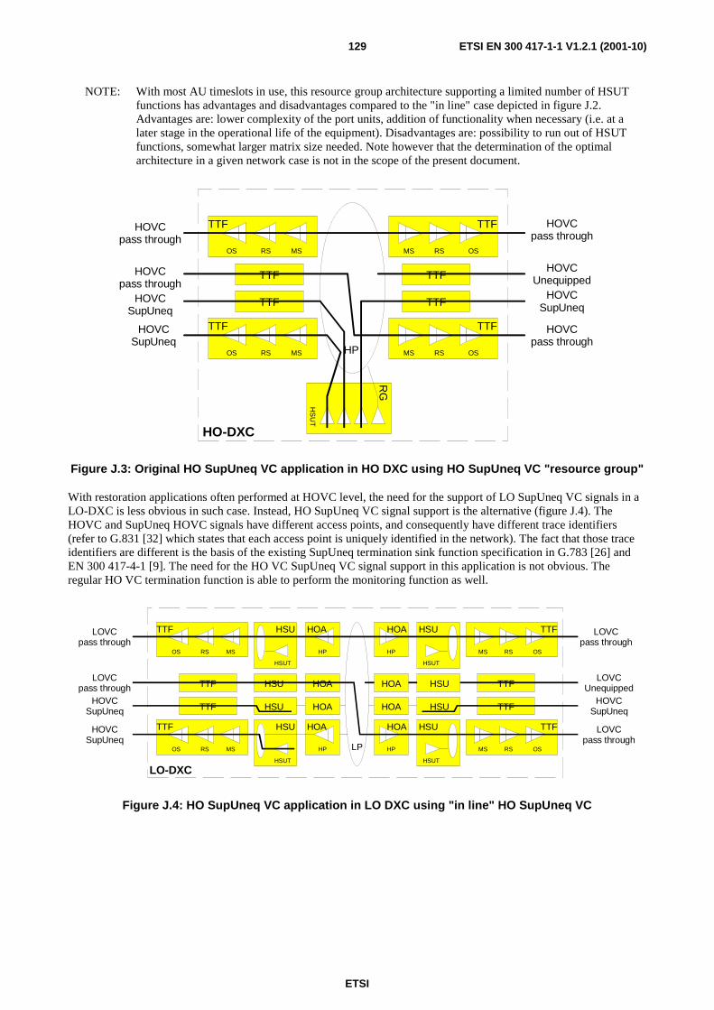
ETSI
ETSI EN 300 417-1-1 V1.2.1 (2001-10)129
NOTE: With most AU timeslots in use, this resource group architecture supporting a limited number of HSUT functions has advantages and disadvantages compared to the "in line" case depicted in figure J.2. Advantages are: lower complexity of the port units, addition of functionality when necessary (i.e. at a later stage in the operational life of the equipment). Disadvantages are: possibility to run out of HSUT functions, somewhat larger matrix size needed. Note however that the determination of the optimal architecture in a given network case is not in the scope of the present document.
HP
HO-DXC
MSRSOS
TTF
TTF
TTF
MSRSOS
TTF
HOVCpass through
HOVCUnequipped
HOVCSupUneq
HOVCpass through
HOVCpass through
HOVCpass through
HOVCSupUneq
HOVCSupUneq
HS
UT
RG
MS RS OS
TTF
TTF
TTF
MS RS OS
TTF
Figure J.3: Original HO SupUneq VC application in HO DXC using HO SupUneq VC "resource group"
With restoration applications often performed at HOVC level, the need for the support of LO SupUneq VC signals in a LO-DXC is less obvious in such case. Instead, HO SupUneq VC signal support is the alternative (figure J.4). The HOVC and SupUneq HOVC signals have different access points, and consequently have different trace identifiers (refer to G.831 [32] which states that each access point is uniquely identified in the network). The fact that those trace identifiers are different is the basis of the existing SupUneq termination sink function specification in G.783 [26] and EN 300 417-4-1 [9]. The need for the HO VC SupUneq VC signal support in this application is not obvious. The regular HO VC termination function is able to perform the monitoring function as well.
LP
LO-DXC
HSUT
MSRSOS
TTF
TTF HSU
HSU
TTF HSU
HSUT
MSRSOS
TTF HSU
LOVCpass through
LOVCUnequipped
HOVCSupUneq
LOVCpass through
LOVCpass through
LOVCpass through
HOVCSupUneq
HOVCSupUneq
MS RS OS
TTF
TTF
TTF
MS RS OS
TTF
HSUT
HSU
HSU
HSU
HSUT
HSU
HP
HP
HOA
HOA
HOA
HOA
HP
HP
HOA
HOA
HOA
HOA
Figure J.4: HO SupUneq VC application in LO DXC using "in line" HO SupUneq VC

ETSI
ETSI EN 300 417-1-1 V1.2.1 (2001-10)130
Annex K (informative): Implementation of the CID immunity measurement Alternating digital signal patterns may be used to verify the adequacy of timing-recovery and low-frequency performance of STM-N equipments.
Appropriate pattern sequences are defined below and in figure J.1.
This test does not attempt to simulate conditions which may occur under anomalous operating conditions to which the equipment may be subjected.
N x A 1 N x A 1 N x A 1 N x A 2 N x C 1 X N x A 2 N x A 2 X
N x 1 0 1 0 1 0 1 0
N x 1 0 1 0 1 0 1 0
D A B D C B D A
T 1 5 0 9 2 0 0 - 9 2 / d 0 9
A l l 1 ' s P s e u d o r a n d o m . 1 / 2 A l l 0 ' s P s e u d o r a n d o m . 1 / 2
1 t e s t p e r i o d
Figure K.1: STM-N pattern dependent test sequence
The specific test patterns are made up of consecutive blocks of data of four types:
a) all ones (zero timing content, high average signal amplitude);
b) pseudo-random data with a mark-density ratio of 1/2;
c) all zeros (zero timing content, low average signal amplitude);
d) a data block consisting of the first row of section overhead bytes for the STM-N system under test.
The test pattern is shown in figure I-1 where the regions A, B, C and D are identified.
The duration of the zero-timing-content periods A and C is made equal to the longest like-element sequences expected in the STM-N signal. A value of nine bytes (72 bits) is provisionally proposed for this.
The duration of the pseudo-random periods should allow recovery of both the zero base line offset of the signal and of the timing recovery circuit following occurrence of the A and C periods. Therefore it should be longer than the longest time constant in the regenerator. In the case of a PLL based clock extraction, this could give a value of the order of 10 000 bits. Taking into account possible limitations of test equipment, a minimum value of 2 000 bits is considered acceptable.
The content of the pseudo-random section should be generated by a scrambler having the same polynomial as defined in EN 300 147 [2]. Ideally, the scrambler should "free-run", i.e. the beginning of the pattern should be uncorrelated with the frame alignment section. This arrangement will ensure that the system experiences the worst possible phasing of the PRBS at some point during the course of the test. However, it is recognized that test equipment limitations may preclude the use of a free running scrambler. Hence it may be necessary to specify a worst-case phasing of the PRBS. This is for further study.
The D-period is defined as the first row of the section overhead of the STM-N signal, including valid C1 bytes (consecutive binary numbers).
It is recommended that this test be applied to SDH systems at any appropriate point in time during the design or production phase. This would be done to demonstrate the ability of both timing-recovery and decision circuits adequately to handle worst-case SDH signals.

ETSI
ETSI EN 300 417-1-1 V1.2.1 (2001-10)131
It should be emphasized that the test pattern may be rejected by or cause malfunction of certain equipments because, for example, the occurrence of the frame alignment bytes within the pattern. The test should therefore only be used for assemblies not so affected, such as timing recovery units, receiver amplifier chains, etc.
However, the test may be applicable in certain cases at the available user ports. It is not proposed as a general acceptance test which might require special defined access ports and connection arrangements within the equipment.
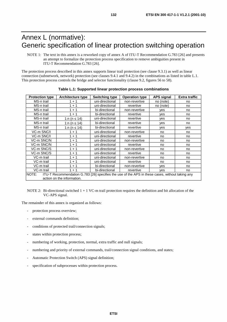
ETSI
ETSI EN 300 417-1-1 V1.2.1 (2001-10)132
Annex L (normative): Generic specification of linear protection switching operation
NOTE 1: The text in this annex is a reworked copy of annex A of ITU-T Recommendation G.783 [26] and presents an attempt to formalize the protection process specification to remove ambiguities present in ITU-T Recommendation G.783 [26].
The protection process described in this annex supports linear trail protection (see clause 9.3.1) as well as linear connection (subnetwork, network) protection (see clauses 9.4.1 and 9.4.2) in the combinations as listed in table L.1. This protection process controls the bridge and selector functionality (clause 9.2, figures 56 to 58).
Table L.1: Supported linear protection process combinations
Protection type Architecture type Switching type Operation type APS signal Extra traffic MS-n trail 1 + 1 uni-directional non-revertive no (note) no MS-n trail 1 + 1 uni-directional revertive no (note) no MS-n trail 1 + 1 bi-directional non-revertive yes no MS-n trail 1 + 1 bi-directional revertive yes no MS-n trail 1:n (n ≤ 14) uni-directional revertive yes no MS-n trail 1:n (n ≤ 14) bi-directional revertive yes no MS-n trail 1:n (n ≤ 14) bi-directional revertive yes yes
VC-m SNC/I 1 + 1 uni-directional non-revertive no no VC-m SNC/I 1 + 1 uni-directional revertive no no VC-m SNC/N 1 + 1 uni-directional non-revertive no no VC-m SNC/N 1 + 1 uni-directional revertive no no VC-m SNC/S 1 + 1 uni-directional non-revertive no no VC-m SNC/S 1 + 1 uni-directional revertive no no
VC-m trail 1 + 1 uni-directional non-revertive no no VC-m trail 1 + 1 uni-directional revertive no no VC-m trail 1 + 1 bi-directional non-revertive yes no VC-m trail 1 + 1 bi-directional revertive yes no
NOTE: ITU-T Recommendation G.783 [26] specifies the use of the APS in these cases, without taking any action on the information.
NOTE 2: Bi-directional switched 1 + 1 VC-m trail protection requires the definition and bit allocation of the VC-APS signal.
The remainder of this annex is organized as follows:
- protection process overview;
- external commands definition;
- conditions of protected trail/connection signals;
- states within protection process;
- numbering of working, protection, normal, extra traffic and null signals;
- numbering and priority of external commands, trail/connection signal conditions, and states;
- Automatic Protection Switch (APS) signal definition;
- specification of subprocesses within protection process.

ETSI
ETSI EN 300 417-1-1 V1.2.1 (2001-10)133
L.1 Protection process overview
APSInterpreterprocess
APSgeneratorprocess
local requestpriorityprocess
RRSN
RRT
P: APSRBSN
LRT:LRSN:LBSN:LSSN:RRT:RRSN:RBSN:RARCH:
External Request TypeExternal Request Signal NumberGlobal Request TypeGlobal Request Signal NumberSignal Request TypeSignal Request Signal Number
RARCH
LBSN
SRT/0
OPERtype
GRT
GRSN
ARCHtype
LBSN
ARCHtype
LRSN
LRT
P:APS
global requestpriorityprocess
ERT ERSN
SWtype
Signal RequestProcess
Signal RequestProcess
Signal RequestProcess
SRT/0
SRT/1
SRT/nLocalBridgeControl
RRCN
GRT
OPERtype
LSSNLocalSelectorControl
RBSN
GRSN
SRT/0
ARCHtype
SWtype
RRSN
EXTRAtraffic
dPAMdSCM dINV
dTMOUT
dTMOUT
dINVdPAM
ERT:ERSN:GRT:GRSN:SRT:SRSN:
Local Request TypeLocal Request Signal NumberLocal Bridge Signal NumberLocal Selector Signal NumberRemote Request TypeRemote Request Signal NumberRemote Bridge Signal NumberRemote Architecture Type
ARCHtype
WTRtime
W1: SF,SD
Wn: SF,SD
P: SF,SD
SFprioritySDpriority
SFpriority=highSDpriority=high
SFprioritySDpriority
ExternalRequestProcess
EXTCMD
GRT/GRSN Reporting
APSmode
Figure L.1: Subprocesses within generic linear trail/connection protection processes

ETSI
ETSI EN 300 417-1-1 V1.2.1 (2001-10)134
Linear protection processes can be characterized by the following (super)set of subprocesses (figure L.1):
Signal Request converts SF and SD signals of a working/protection trail/connection signal into a (signal) request type and trail/connection number;
External Request converts the external commands into an (external) request type and signal number;
Local Request Priority determines the highest priority local request;
APS Interpretation converts the APS signal into a (remote) request type, request signal number, bridged signal number, and architecture type (if applicable);
Global Request Priority determines the highest global request type comparing local and remote (if applicable) requests;
Local Bridge Control determines which of the normal/extra traffic signals is bridged to the protection trail/connection;
Local Selector Control determines which of the normal/extra traffic signals is connected to/extracted from the protection trail/connection;
APS Generation converts the global request type, global request signal number, local bridged signal number, and local architecture into the APS signal;
Reporting reports the status (local, remote) of the protection process; remote status if APS signal is supported.
A specific protection application is characterized by the following parameter set:
Table L.2
Parameter Value options Architecture type (ARCHtype) 1 + 1, 1:n Switching type (SWtype) uni-directional, bi-directional Operation type (OPERtype) revertive, non-revertive APS signal (APSmode) true, false Wait-To-Restore time (WTRtime) in the order of 0-12 minutes Switching time ≤ 50 ms Hold-off time (HOtime) 0 to 10 seconds in steps of the order of 100 ms Protection type (PROTtype) SNC/I, SNC/N, SNC/S, trail Signal switch conditions: SF = SSF (SNC/I)
SF = TSF (SNC/N, SNC/S, trail), SD = TSD (SNC/N, SNC/S, trail)
External commands (EXTCMD) LO-#0, FSw-#i, MSw-#i, EXER-#i, CLR Extra traffic (EXTRAtraffic) true, false Priority of SF and SD (SFpriority, SDpriority)
low, high
L.2 External switch commands definition A switch command issues an appropriate external request. Only one switch request can be issued per protection group. Switch commands are listed below in the descending order of priority and the functionality of each is described.
NOTE 1: The addition of the Lockout for Working #i command is for further study.

ETSI
ETSI EN 300 417-1-1 V1.2.1 (2001-10)135
The function shall generate an automatic response confirming that the request was executed, or stating that the request was denied for a particular reason.
1) Clear (CLR): Clears all switch commands listed below.
2) Lockout of protection (LO): Request to deny all normal signals (and the extra traffic signal, if applicable) access to the protection trail/connection.
NOTE 2: Request is honoured unless an equal priority switch command is in effect. If the request is denied, it is released and forgotten.
3) Forced switch #i (FSw-#i): Request to switch normal signal #i (1 ≤ i ≤ n, n ≤ nmax) to the protection
trail/connection, or request to switch extra traffic signal #nmax + 1 to the protection trail/connection, or (for the
case of 1 + 1 non-revertive systems) request (FSw-#0) to switch normal signal to working trail/connection.
NOTE 3: Request is honoured unless an equal or higher priority switch command is in effect or (for the case an APS signal is in use) SF condition exists on the protection trail/connection. If the request is denied, it is released and forgotten.
NOTE 4: For 1 + 1 non-revertive systems, "forced switch no normal signal (FSw-#0)" transfers the normal signal from protection to the working trail/connection, unless an equal or higher priority request is in effect. Since forced switch has higher priority than SF or SD on the working trail/connection, this command will be carried out regardless of the condition of the working trail/connection.
NOTE 5: For 1: n architectures, "forced switch to extra traffic (FSw-#nmax + 1)" forces the extra traffic signal to the
protection trail/connection and prevents normal signals to be transported over protection.
4) Manual switch #i (MSw-#i): Request to switch normal signal #i (1 ≤ i ≤ n, n ≤ nmax) to the protection
trail/connection, or (for the case of 1 + 1 non-revertive systems) request (MSw-#0) to switch normal signal to working trail/connection.
NOTE 6: Request is honoured unless a defect condition exists on other trail/connections (including the protection trail/connection) or an equal or higher priority switch command is in effect. If the request is denied, it is released and forgotten.
NOTE 7: For 1 + 1 non-revertive systems, "manual switch no normal signal (MSw-#0)" transfers the normal signal back from protection to the working trail/connection, unless an equal or higher priority request is in effect. Since manual switch has lower priority than SF or SD on a working trail/connection, this command will be carried out only if the working trail/connection is not in SF or SD condition.
5) Exercise #i (EXER-#i): Request for an exercise to check responses on APS bytes for normal signal #i (1 ≤ i ≤ n, n ≤ nmax). The switch is not actually completed, i.e. the selector is released by an exercise request
on either the sent or the received and acknowledged K1 byte.
NOTE 8: Request is honoured unless the protection signal is in use.
The following table presents alternative user interface external command strings for the case of 1 + 1 protection architectures. Note that the generic names will be used in the present document.
Table L.3
Generic Alternative for 1 + 1 revertive
Alternative for 1 + 1 non-revertive
Result
LO (#0) LO - normal signal connected to working trail/connection
FSw-#0 - FSw-(to)-W normal signal connected to working trail/connection
FSw-#1 FSw-(to)-P FSw-(to)-P normal signal connected to protection trail/connection
MSw-#0 - MSw-(to)-W normal signal connected to working trail/connection
MSw-#1 MSw-(to)-P MSw-(to)-P normal signal connected to protection trail/connection
ETSI
ETSI EN 300 417-1-1 V1.2.1 (2001-10)136
L.3 Conditions of working and protection trail/connections
Working and protection trail/connection (signals) have a condition associated with them: fault free, signal fail, signal degrade. The condition is communicated with the protection process by means of the SF and SD signals within the characteristic or adapted information of the working/protection trail/connection signal.
L.4 States within protection process The protection process has a number of so called states associated with it: no request, do not revert, reverse request, and wait to restore. A description of the effect of the states is presented:
Wait to restore (WTR): In the revertive mode of operation, the normal signal will be restored (i.e. the signal on the protection trail/connection will be switched back to the working trail/connection) when the working trail/connection has recovered from the fault.
To prevent frequent operation of the selector due to an intermittent fault, a failed working trail/connection shall become fault-free. After the failed trail/connection meets this criterion, (and no other externally initiated commands are present) a fixed period of time will elapse before it is used again by the normal signal. During this WTR state, switching will not occur.
An SF or SD condition will override the WTR. After the WTR period is completed, a No Request state will be entered. Switching will then occur from the protection trail/connection to the working trail/connection.
Reverse request: For the case of bi-directional switching, a reverse request is returned for exerciser and all other requests of higher priority. This clearly identifies which end originated the switch request.
If the head end had also originated an identical request (not yet confirmed by a reverse request) for the same signal, then both ends would continue transmitting (in the APS signals) the identical request type (RT) and signal number (RSN) and perform the requested switch action.
In uni-directional switching, reverse request is never indicated.
Both wait-to-restore and do not revert requests in the RT fields of the transmitted APS signal are normally acknowledged by a reverse request in the RT field of the received APS signal. However, no request is acknowledged by another no request received.
Do not revert: In the non-revertive mode of operation, assuming the normal signal is on protection when the working trail/connection is repaired or a switch command is released, the tail end maintains the selection and issues LRT/LRSN = DNR/1 (do not revert for normal signal 1).
For the case of bi-directional switching, the head end also maintains the selection and continues indicating reverse request. The do not revert is removed when pre-empted by a defect condition or an external request.
No request: This state represents the inactive state of the request processes (signal, external, local, remote, and global request processes). None of the trail/connection signal conditions is active, none of the external commands is active, and none of the states described above is active.

ETSI
ETSI EN 300 417-1-1 V1.2.1 (2001-10)137
L.5 Numbering of working, protection, normal, extra traffic, null signals
The protection trail/connection shall be referred to as number "0". The working trails/connections are numbered "1", "2", etc. The assignment of these numbers to physical entities in a network element is equipment specific and not within the scope of the present document.
W1 W2 Wn P
N1 N2 Nn E
W1 W2 Wn P0
N1 N2 Nn E
working trails, orworking connections
protection trail, orprotection connection
normal signals extra traffic signal
01 2 n
nmax+1
Figure L.2: Definitions of working trail/connection, protection trail connection, normal and extra traffic signal
The normal signals shall be numbered (equivalent to the working trails/connections) "1", "2", etc. In 1:n (n = 1,2,3,..,nmax) protection architectures normal signal #i shall be transported over working trail/connection #i or over
the protection trail/connection. For the case of section layer protection, the assignment of these numbers to physical entities in a network element is equipment specific and not within the scope of the present document. For the case of path layer protection, the assignment of these numbers to physical entities in a network element shall be provisionable via configuration management.
NOTE: The value of nmax is protection application dependent.
The extra traffic signal (supported in 1:n architectures only) shall be referred to as number nmax + 1. The extra traffic
signal shall be transported over the protection trail/connection when this one is not transporting a normal signal and the protection trail/connection is not "locked out".
The null signal, present in 1:n architectures only, shall be referred to as number "0". When none of the normal signals nor an extra traffic signal is transported over the protection trail/connection, the null signal shall be transported. This can be any signal (e.g. one of the normal signals, a test signal, an all-ONEs signal).
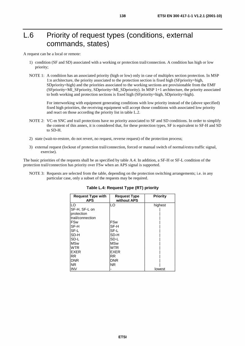
ETSI
ETSI EN 300 417-1-1 V1.2.1 (2001-10)138
L.6 Priority of request types (conditions, external commands, states)
A request can be a local or remote:
1) condition (SF and SD) associated with a working or protection trail/connection. A condition has high or low priority;
NOTE 1: A condition has an associated priority (high or low) only in case of multiplex section protection. In MSP 1:n architecture, the priority associated to the protection section is fixed high (SFpriority=high, SDpriority=high) and the priorities associated to the working sections are provisionable from the EMF (SFpriority=MI_SFpriority, SDpriority=MI_SDpriority). In MSP 1+1 architecture, the priority associated to both working and protection sections is fixed high (SFpriority=high, SDpriority=high).
For interworking with equipment generating conditions with low priority instead of the (above specified) fixed high priorities, the receiving equipment will accept those conditions with associated low priority and react on those according the priority list in table L.2.
NOTE 2: VC-m SNC and trail protections have no priority associated to SF and SD conditions. In order to simplify the content of this annex, it is considered that, for these protection types, SF is equivalent to SF-H and SD to SD-H.
2) state (wait-to-restore, do not revert, no request, reverse request) of the protection process;
3) external request (lockout of protection trail/connection, forced or manual switch of normal/extra traffic signal, exercise).
The basic priorities of the requests shall be as specified by table A.4. In addition, a SF-H or SF-L condition of the protection trail/connection has priority over FSw when an APS signal is supported.
NOTE 3: Requests are selected from the table, depending on the protection switching arrangements; i.e. in any particular case, only a subset of the requests may be required.
Table L.4: Request Type (RT) priority
Request Type with APS
Request Type without APS
Priority
LO LO highest SF-H, SF-L on protection trail/connection
| | |
FSw FSw | SF-H SF-H | SF-L SF-L | SD-H SD-H | SD-L SD-L | MSw MSw | WTR WTR | EXER EXER | RR RR | DNR DNR | NR NR | INV - lowest
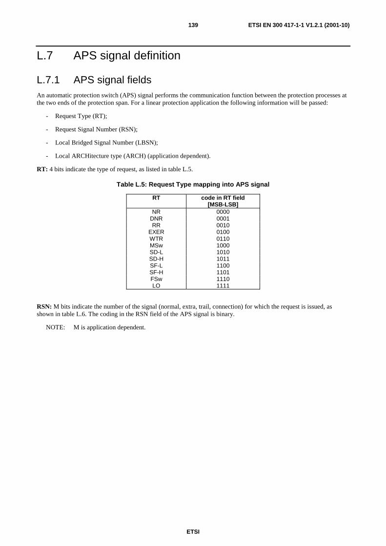
ETSI
ETSI EN 300 417-1-1 V1.2.1 (2001-10)139
L.7 APS signal definition
L.7.1 APS signal fields An automatic protection switch (APS) signal performs the communication function between the protection processes at the two ends of the protection span. For a linear protection application the following information will be passed:
- Request Type (RT);
- Request Signal Number (RSN);
- Local Bridged Signal Number (LBSN);
- Local ARCHitecture type (ARCH) (application dependent).
RT: 4 bits indicate the type of request, as listed in table L.5.
Table L.5: Request Type mapping into APS signal
RT code in RT field [MSB-LSB]
NR 0000 DNR 0001 RR 0010
EXER 0100 WTR 0110 MSw 1000 SD-L 1010 SD-H 1011 SF-L 1100 SF-H 1101 FSw 1110 LO 1111
RSN: M bits indicate the number of the signal (normal, extra, trail, connection) for which the request is issued, as shown in table L.6. The coding in the RSN field of the APS signal is binary.
NOTE: M is application dependent.
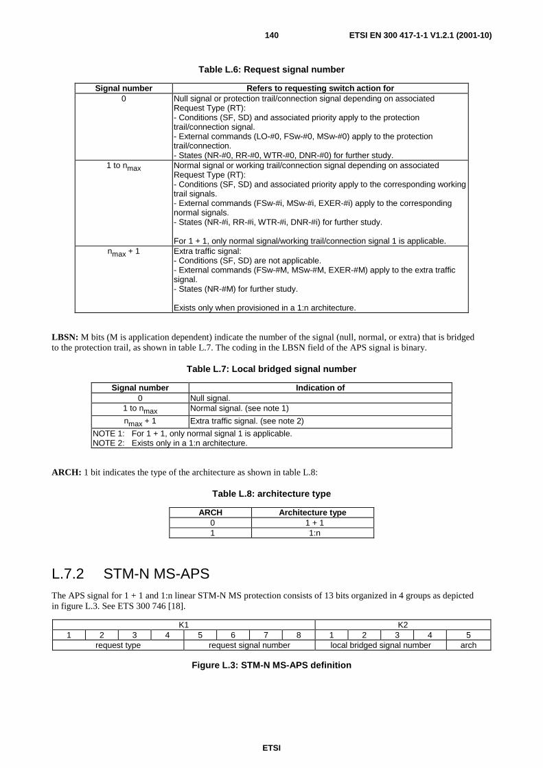
ETSI
ETSI EN 300 417-1-1 V1.2.1 (2001-10)140
Table L.6: Request signal number
Signal number Refers to requesting switch action for 0 Null signal or protection trail/connection signal depending on associated
Request Type (RT): - Conditions (SF, SD) and associated priority apply to the protection trail/connection signal. - External commands (LO-#0, FSw-#0, MSw-#0) apply to the protection trail/connection. - States (NR-#0, RR-#0, WTR-#0, DNR-#0) for further study.
1 to nmax Normal signal or working trail/connection signal depending on associated Request Type (RT): - Conditions (SF, SD) and associated priority apply to the corresponding working trail signals. - External commands (FSw-#i, MSw-#i, EXER-#i) apply to the corresponding normal signals. - States (NR-#i, RR-#i, WTR-#i, DNR-#i) for further study. For 1 + 1, only normal signal/working trail/connection signal 1 is applicable.
nmax + 1 Extra traffic signal: - Conditions (SF, SD) are not applicable. - External commands (FSw-#M, MSw-#M, EXER-#M) apply to the extra traffic signal. - States (NR-#M) for further study. Exists only when provisioned in a 1:n architecture.
LBSN: M bits (M is application dependent) indicate the number of the signal (null, normal, or extra) that is bridged to the protection trail, as shown in table L.7. The coding in the LBSN field of the APS signal is binary.
Table L.7: Local bridged signal number
Signal number Indication of 0 Null signal.
1 to nmax Normal signal. (see note 1)
nmax + 1 Extra traffic signal. (see note 2)
NOTE 1: For 1 + 1, only normal signal 1 is applicable. NOTE 2: Exists only in a 1:n architecture.
ARCH: 1 bit indicates the type of the architecture as shown in table L.8:
Table L.8: architecture type
ARCH Architecture type 0 1 + 1 1 1:n
L.7.2 STM-N MS-APS The APS signal for 1 + 1 and 1:n linear STM-N MS protection consists of 13 bits organized in 4 groups as depicted in figure L.3. See ETS 300 746 [18].
K1 K2 1 2 3 4 5 6 7 8 1 2 3 4 5
request type request signal number local bridged signal number arch
Figure L.3: STM-N MS-APS definition
ETSI
ETSI EN 300 417-1-1 V1.2.1 (2001-10)141
L.7.3 STM-N VC-APS VC APS definition and bit allocation is for further study.
L.8 Switch performance: switching and holdoff times For automatically initiated conditions (i.e. SF and SD), the protection switch completion time shall be less than 50 ms. Protection switch completion time excludes the detection time necessary to initiate the protection switch, and hold-off time. It includes the transmission transfer delay time when bi-directional and 1:n uni-directional switching is selected.
NOTE 1: The allocation of the maximum protection switching completion time is currently under study in ITU-T.
NOTE 2: When bi-directional and 1:n uni-directional switching is required, the transfer delay time may limit the length of the protected trail/connection. This is due to the transfer delay of protection information that is to be communicated between the two ends via the APS signals. Alternatively, the protection switch time for such a case could be defined as a value with 3 components: a fixed (basic) value, the length of the protection trail/connection, and the number of network elements and their processing level (e.g. AU only, AU and TU). This is for further study.
Hold-off times are useful to stagger protection switching activation between various transport layers or within the same transport layer. It shall be possible to provision for each protection group (see clause 9.2.1) whether or not a holdoff timer is enabled. The objective is that the holdoff time should be selectable per protection group on an individual basis. As a minimum, a single holdoff time per layer shall be supported, applicable for all protection groups within that layer. The defect condition should be continuously monitored for the full duration of the hold-off time before switching occurs. The hold-off time should therefore be provisionable from 0 to 10 seconds in steps of 100 ms.
NOTE 3: The specification of the operation of a holdoff timer within the protection switch process is for further study.
The service interruption due to the switching on an external command (CLR, LO, FSw, MSw) shall be limited to the switch-over time.
L.9 Subprocesses This clause specifies in a more or less formal manner the operation of the subprocesses within the protection process.
NOTE 1: SDL specification for the following pseudo code is for further study.
NOTE 2: The addition of a Lockout of Working #i command is for further study.
NOTE 3: The addition of a holdoff timer is for further study.
Signal request (type & signal number) processes
This process shall transfer the input SF and SD signals from a trail/connection (either protection (#0), or working #1,.., or working #n) into a Signal Request Type (SRT) and Signal Request Signal Number (SRSN):
- The SRSN shall be "0" (zero) for the protection trail/connection and "i" (1 ≤ i ≤ n) for working trail/connection #i.
- The SRT shall be generated based on the inputs SF, SD, SFpriority, SDpriority, as follows:
if (SF==true)
then if (SFpriority==high)
then SRT= SF-H
else SRT=SF-L
fi
ETSI
ETSI EN 300 417-1-1 V1.2.1 (2001-10)142
else if (SD==true)
then if (SDpriority==high)
then SRT=SD-H
else SRT=SD-L
fi
else SRT= NR
fi
fi
External request (type & signal number) process
This process shall transfer the external commands (EXTCMD) into an External Request Type (ERT) and External Request Signal Number (ERSN):
- The ERSN shall be "0" (zero) if no normal signal is indicated, "i" (1 ≤ i ≤ nmax) for normal signal #i, and
"nmax+1" for the extra traffic signal.
- The ERT/ERN shall be generated as follows:
do on external command reception
start 2,5 s Completion Timer (CTimer)
if (EXTCMD==clear)
then ERT=NR
ERSN=0
else if (EXTCMD==lockout of protection)
then ERT=LO
ERSN=0
else if (EXTCMD==forced switch-#i)
then ERT=FSw
ERSN=#i
else if (EXTCMD==manual switch-#i)
then ERT=MSw
ERSN=#i
else if (EXTCMD==exercise-#i)
then ERT=EXER
ERSN=#i
fi
fi
fi
fi
ETSI
ETSI EN 300 417-1-1 V1.2.1 (2001-10)143
fi
wait until CTimer is expired
then {check if FSw request is denied, then release external (FSw) request}
if (ERT==FSw) and not [((GRT==FSw) or (GRT==RR)) and (GRSN==ERSN) ]
then ERT=NR
ERSN=0
fi
{check if LO request is denied, then release external (LO) request}
if (ERT==LO) and not [((GRT==LO) or (GRT==RR)) and (GRSN==ERSN)]
then ERT=NR
ERSN=0
{check if MSw request is denied, then release external (MSw) request}
if (ERT==MSw) and not [((GRT==MSw) or (GRT==RR)) and (GRSN==ERSN) ]
then ERT=NR
ERSN=0
fi
{check if EXER request is denied, then release external (EXER) request}
if (ERT==EXER) and not [((GRT==EXER) or (GRT==RR)) and(GRSN==ERSN)]
then ERT=NR
ERSN=0
fi
tiaw
od
NOTE 4: The above clearing of external requests is continuously active after expiry of 2,5 seconds timer. If the external command was acknowledged initially, but is overruled later on, the external command is dropped consequently.
Local request (type & signal number) priority process
This process shall determine the highest priority local request. It shall evaluate the status of the protection and working input signals (SRT/SRSN #0 to SRT/SRSN #n), the external command (ERT/ERSN), and protection parameters OPERtype and EXTRAtraffic by a three step priority logic:
1) The highest priority local request shall be determined over the set of SRT/0, SRT/1,.., SRT/n, ERT inputs based on the descending order of request type priorities in table 0.
2) If there is at least one SRT that is higher than the ERT, and if two or more trails/connections (working/protection) have the same highest request type (SRT), the trail/connection with the lowest number shall take priority, unless the priority of the highest SRT is identical to the current LRT.
NOTE 5: The protection trail/connection has the highest priority due to its number (#0).

ETSI
ETSI EN 300 417-1-1 V1.2.1 (2001-10)144
NOTE 6: When normal signal number B is already transported via the protection trail/connection, it will not be replaced by normal signal number A (A < B) if both working trail/connection A and working trail/connection B have the same defect condition with the same priority (i.e. SRT/A == SRT/B is e.g. SF-H).
3) If highest priority request (SRT, ERT) detected under 1. and 2. is no-request (NR), the LRT depends on the history of the protection process, the operation type, and the presence of an extra traffic signal.
The following pseudo code describes this 3 step process:
if ((LRT==WTR) and (ERT==EXER))
then {exercise command is of lower priority then wait-to-restore state}
LRTnew=NR
LRSNnew=0
LRsource=signal
else
LRTnew = ERT {initialize process}
LRSNnew=ERSN
LRsource=external
fi
for i==0 to n
do {find highest priority local request active}
if (LRTnew < SRT/i)
then LRTnew=SRT/i
LRSNnew=i
LRsource=signal
fi
od
if (LRTnew==NR)
then {No-Request case}
if (OPERtype==non-revertive)
then {non-revertive case}
if (LRSN==1) {check if do not revert needs to be generated}
then LRT= DNR
else LRT=NR
fi
else {revertive case}
if ( ((LRT==SF) or (LRT==SD) or (LRT==WTR)) and (WTRtimer > 0) )
then {previous request was a SF or SD, or a WTR running}

ETSI
ETSI EN 300 417-1-1 V1.2.1 (2001-10)145
LRT=WTR
else {previous request was no-request}
LRT=NR
if (EXTRAtraffic==true)
then {extra traffic supported}
LRSN=nmax+1
else {extra traffic not supported}
LRSN=0
fi
fi
fi
else {Request case}
if (LRsource==external)
then {external local request has highest priority}
LRT=LRTnew
LRSN=LRSNnew
else {a signal has highest local request priority}
if (LRTnew≠LRT)
then {new request not equal to existing local request}
LRT=LRTnew
LRSN=LRSNnew
else {new request equal to existing local request}
if (SRT/LRSN≠LRTnew)
then {existing local request source has changed request}
LRSN=LRSNnew
fi
fi
fi
fi
In revertive mode of operation a wait-to-restore timer (WTRtimer) shall be supported. The wait-to-restore period (WTRtime) shall be provisionable in the order of 0 - 12 minutes, in steps of Y seconds. The timer shall be set to the provisioned value when the SF or SD defect condition is active (LRT=SF or LRT=SD). The timer shall be started when the last defect condition (SF, SD) clears; i.e. when all SRTs indicate No Request (NR). The WTR timer shall count down to zero. The WTR timer shall be reset to zero (deactivates earlier) if the Global Request Type (GRT) no longer indicates wait-to-restore, i.e. when any request of higher priority pre-empts this state.
The value of Y is for further study.

ETSI
ETSI EN 300 417-1-1 V1.2.1 (2001-10)146
APS interpretation process
This process shall translate the accepted APS signal into the signals Remote Request Type (RRT), Remote Request Signal Number (RRSN), Remote Bridged Signal Number (RBSN) and Remote Architecture type (RARCH), as follows:
- RRT as specified in table A.9;
- RRSN = AcRSN;
- RBSN = AcLBSN;
- RARCH = AcARCH.
NOTE 7: AcRSN and AcLBSN can be out of range due to a fault or bit errors. For such case an invalid defect will be detected.
Table L.9: Remote Request Type (RRT) interpretation from APS signal
AcRT RRT 0000 NR 0001 DNR 0010 RR 0011 invalid 0100 EXER 0101 invalid 0110 WTR 0111 invalid 1000 MSw 1001 invalid 1010 SD-L 1011 SD-H 1100 SF-L 1101 SF-H 1110 FSw 1111 LO
Defects:
If the received APS Architecture (RARCH) value differs from the local architecture type (ARCHtype) for a period of 50 ms, a Protection Architecture Mismatch defect (dPAM) shall be detected. The defect shall be cleared when the there is a match again.
If the request type bits (RT) in the APS signal indicate an invalid request code, or the RSN or LBSN indicate a non-existing trail/connection/normal signal number, an invalid command defect (dINV) shall be detected when the condition exist for 50 ms. The defect shall be cleared when the RT indicate a valid code and the RSN or LBSN indicate an existing signal number. Neither shall be considered remote requests for a locally locked out normal signal.
Global request priority process
The local request (LRT,LRSN) and the remote request (RRT,RRSN) shall be compared to decide which has priority. The priority shall be determined according to the descending order of priorities in table A.4. Note that a received reverse request shall not be considered in the comparison.
The result, Global Request Type (GRT) and Global Request Signal Number (GRSN) shall be determined as follows:
if ( (SWtype==bi-directional) and (SRT/0≠SF) and (RRT≠RR) and
[(RRT>LRT) or
((RRT==LRT) and (RRT>NR) and (GRT==RR)) or
((RRT==LRT) and (RRT>NR) and (GRT≠RR) and (RRSN<LRSN)) ])
ETSI
ETSI EN 300 417-1-1 V1.2.1 (2001-10)147
then {bi-directional switching, no SF on protection trail/connection, no reverse request, and either "remote request overrules local request" or "remote request equals local request and was already accepted" or "remote request equals local request and remote signal number is lower than local signal number"}
GRT=RR
GRSN=RRSN
else {uni-directional switching or SF on protection trail/connection or reverse request received or local request overrules remote request or local and remote requests are equal and local signal number is less or equal remote signal number}
GRT=LRT
GRSN=LRSN
fi
NOTE 8: See clause K.4.
Defects:
If a head end response on a tail end request does not comply to the protocol (i.e. "not ((RRT==RR and RRSN==GRSN) or RRT≥LRT)") within a period of 50 ms, an acknowledge timeout defect (dTMOUT) shall be detected. The defect shall be cleared when the head-end response complies again or if the protection trail/connection is in SF condition.
Bridge control process
This process controls which of the normal/extra traffic signals is bridged to the protection trail/connection. Its operation shall be as follows:
if (ARCHtype==1+1)
then {1+1 architecture}
LBSN=1 {normal #1 signal permanent bridged}
else {1:n architecture}
if [(SRT/0≠SF) and (not (dPAM or dSCM or dTMOUT or dINV))]
then {no SF on protection and no failure of protocol}
LBSN=RRSN
else {SF on protection or failure of protocol}
if (SWtype==bi-directional)
then LBSN=0
fi
fi
fi
NOTE 9: When the protection trail/connection is not in use, null signal is indicated on both RSN and LBSN fields in the APS signal. Any normal signal may be bridged to the protection trail/connection at the head end. The tail end shall not assume or require any specific signal.
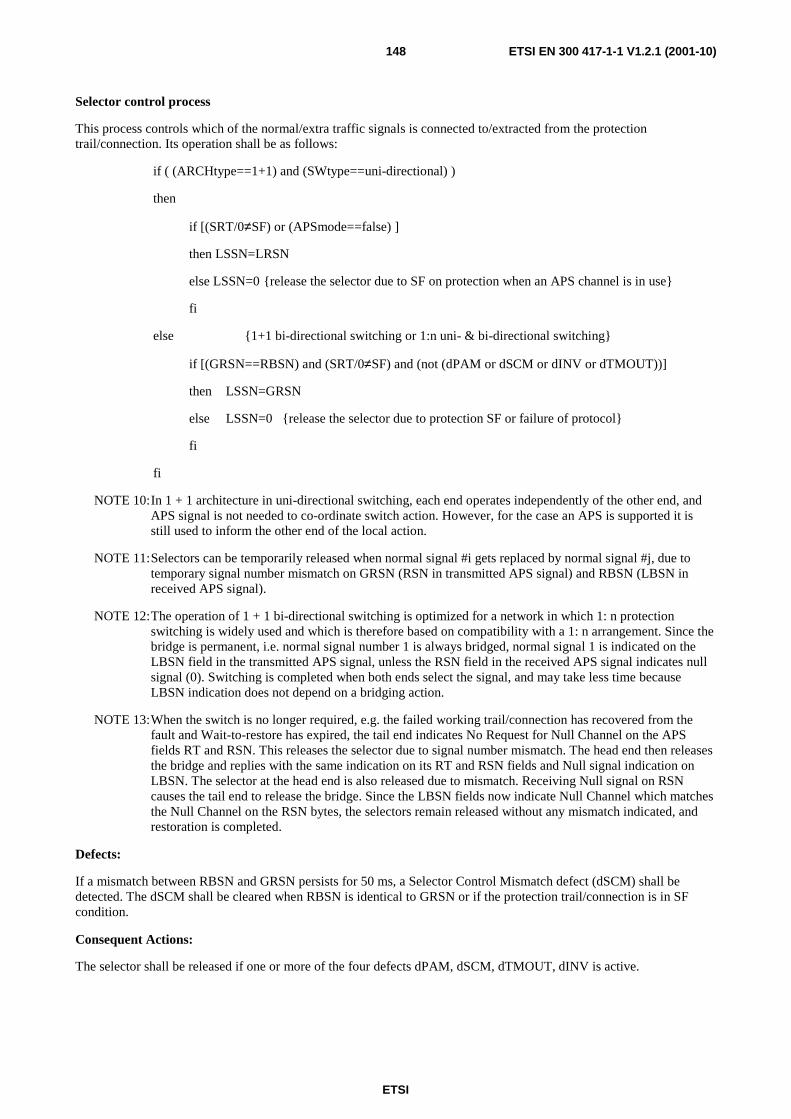
ETSI
ETSI EN 300 417-1-1 V1.2.1 (2001-10)148
Selector control process
This process controls which of the normal/extra traffic signals is connected to/extracted from the protection trail/connection. Its operation shall be as follows:
if ( (ARCHtype==1+1) and (SWtype==uni-directional) )
then
if [(SRT/0≠SF) or (APSmode==false) ]
then LSSN=LRSN
else LSSN=0 {release the selector due to SF on protection when an APS channel is in use}
fi
else {1+1 bi-directional switching or 1:n uni- & bi-directional switching}
if [(GRSN==RBSN) and (SRT/0≠SF) and (not (dPAM or dSCM or dINV or dTMOUT))]
then LSSN=GRSN
else LSSN=0 {release the selector due to protection SF or failure of protocol}
fi
fi
NOTE 10: In 1 + 1 architecture in uni-directional switching, each end operates independently of the other end, and APS signal is not needed to co-ordinate switch action. However, for the case an APS is supported it is still used to inform the other end of the local action.
NOTE 11: Selectors can be temporarily released when normal signal #i gets replaced by normal signal #j, due to temporary signal number mismatch on GRSN (RSN in transmitted APS signal) and RBSN (LBSN in received APS signal).
NOTE 12: The operation of 1 + 1 bi-directional switching is optimized for a network in which 1: n protection switching is widely used and which is therefore based on compatibility with a 1: n arrangement. Since the bridge is permanent, i.e. normal signal number 1 is always bridged, normal signal 1 is indicated on the LBSN field in the transmitted APS signal, unless the RSN field in the received APS signal indicates null signal (0). Switching is completed when both ends select the signal, and may take less time because LBSN indication does not depend on a bridging action.
NOTE 13: When the switch is no longer required, e.g. the failed working trail/connection has recovered from the fault and Wait-to-restore has expired, the tail end indicates No Request for Null Channel on the APS fields RT and RSN. This releases the selector due to signal number mismatch. The head end then releases the bridge and replies with the same indication on its RT and RSN fields and Null signal indication on LBSN. The selector at the head end is also released due to mismatch. Receiving Null signal on RSN causes the tail end to release the bridge. Since the LBSN fields now indicate Null Channel which matches the Null Channel on the RSN bytes, the selectors remain released without any mismatch indicated, and restoration is completed.
Defects:
If a mismatch between RBSN and GRSN persists for 50 ms, a Selector Control Mismatch defect (dSCM) shall be detected. The dSCM shall be cleared when RBSN is identical to GRSN or if the protection trail/connection is in SF condition.
Consequent Actions:
The selector shall be released if one or more of the four defects dPAM, dSCM, dTMOUT, dINV is active.
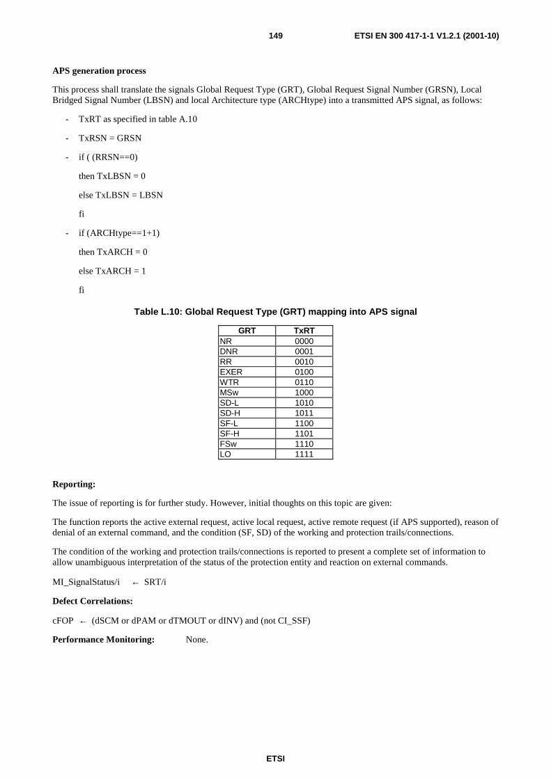
ETSI
ETSI EN 300 417-1-1 V1.2.1 (2001-10)149
APS generation process
This process shall translate the signals Global Request Type (GRT), Global Request Signal Number (GRSN), Local Bridged Signal Number (LBSN) and local Architecture type (ARCHtype) into a transmitted APS signal, as follows:
- TxRT as specified in table A.10
- TxRSN = GRSN
- if ( (RRSN==0)
then TxLBSN = 0
else TxLBSN = LBSN
fi
- if (ARCHtype==1+1)
then TxARCH = 0
else TxARCH = 1
fi
Table L.10: Global Request Type (GRT) mapping into APS signal
GRT TxRT NR 0000 DNR 0001 RR 0010 EXER 0100 WTR 0110 MSw 1000 SD-L 1010 SD-H 1011 SF-L 1100 SF-H 1101 FSw 1110 LO 1111
Reporting:
The issue of reporting is for further study. However, initial thoughts on this topic are given:
The function reports the active external request, active local request, active remote request (if APS supported), reason of denial of an external command, and the condition (SF, SD) of the working and protection trails/connections.
The condition of the working and protection trails/connections is reported to present a complete set of information to allow unambiguous interpretation of the status of the protection entity and reaction on external commands.
MI_SignalStatus/i ← SRT/i
Defect Correlations:
cFOP ← (dSCM or dPAM or dTMOUT or dINV) and (not CI_SSF)
Performance Monitoring: None.
ETSI
ETSI EN 300 417-1-1 V1.2.1 (2001-10)150
Annex M (informative): Bibliography
• IEC 825: "Safety of laser products".
• ITU-T handbook: "Handbook on Quality of Service and Network Performance".
• ITU-T Recommendation G.775 (1998): "Loss of signal (LOS) and alarm indication signal (AIS) defect detection and clearance criteria".
• ITU-T Recommendation G.811 (1997): "Timing requirements at the outputs of primary reference clocks suitable for plesiochronous operation of international digital links".
• ITU-T Recommendation G.823 (1993): "The control of jitter and wander within digital networks which are based on the 2 048 kbit/s hierarchy".
• ETSI TS 100 746: "Transmission and Multiplexing (TM); Synchronous Digital Hierarchy (SDH); Network protection schemes; Automatic Protection Switch (APS) protocols and operation".
• ETSI EN 300 416: "Network Aspects (NA); Availability performance of path elements of international digital paths".

ETSI
ETSI EN 300 417-1-1 V1.2.1 (2001-10)151
History
Document history
Edition 1 January 1996 Publication as ETS 300 417-1-1
V1.1.2 November 1998 Publication
V1.1.3 May 1999 Publication
V1.2.1 June 2001 One-step Approval Procedure OAP 20011012: 2001-06-13 to 2001-10-12
V1.2.1 October 2001 Publication