etsi gr nfv-ifa 012 v3.1 · 7 etsi gr nfv-ifa 012 v3.1.1 (2018-10) intellectual property rights...
TRANSCRIPT

ETSI GR NFV-IFA 012 V3.1.1 (2018-10)
Network Functions Virtualisation (NFV) Release 3; Management and Orchestration;
Report on Os-Ma-Nfvo reference point - application and service management use cases and recommendations
Disclaimer
The present document has been produced and approved by the Network Functions Virtualisation (NFV) ETSI Industry Specification Group (ISG) and represents the views of those members who participated in this ISG.
It does not necessarily represent the views of the entire ETSI membership.
GROUP REPORT
ETSI
ETSI GR NFV-IFA 012 V3.1.1 (2018-10) 2
Reference DGR/NFV-IFA012
Keywords MANO, network, NFV, service, use case
ETSI
650 Route des Lucioles F-06921 Sophia Antipolis Cedex - FRANCE
Tel.: +33 4 92 94 42 00 Fax: +33 4 93 65 47 16
Siret N° 348 623 562 00017 - NAF 742 C
Association à but non lucratif enregistrée à la Sous-Préfecture de Grasse (06) N° 7803/88
Important notice
The present document can be downloaded from: http://www.etsi.org/standards-search
The present document may be made available in electronic versions and/or in print. The content of any electronic and/or print versions of the present document shall not be modified without the prior written authorization of ETSI. In case of any
existing or perceived difference in contents between such versions and/or in print, the only prevailing document is the print of the Portable Document Format (PDF) version kept on a specific network drive within ETSI Secretariat.
Users of the present document should be aware that the document may be subject to revision or change of status. Information on the current status of this and other ETSI documents is available at
https://portal.etsi.org/TB/ETSIDeliverableStatus.aspx
If you find errors in the present document, please send your comment to one of the following services: https://portal.etsi.org/People/CommiteeSupportStaff.aspx
Copyright Notification
No part may be reproduced or utilized in any form or by any means, electronic or mechanical, including photocopying and microfilm except as authorized by written permission of ETSI.
The content of the PDF version shall not be modified without the written authorization of ETSI. The copyright and the foregoing restriction extend to reproduction in all media.
© ETSI 2018.
All rights reserved.
DECTTM, PLUGTESTSTM, UMTSTM and the ETSI logo are trademarks of ETSI registered for the benefit of its Members. 3GPPTM and LTETM are trademarks of ETSI registered for the benefit of its Members and
of the 3GPP Organizational Partners. oneM2M™ logo is a trademark of ETSI registered for the benefit of its Members and
of the oneM2M Partners GSM® and the GSM logo are trademarks registered and owned by the GSM Association.

ETSI
ETSI GR NFV-IFA 012 V3.1.1 (2018-10) 3
Contents
Intellectual Property Rights ................................................................................................................................ 7
Foreword ............................................................................................................................................................. 7
Modal verbs terminology .................................................................................................................................... 7
1 Scope ........................................................................................................................................................ 8
2 References ................................................................................................................................................ 8
2.1 Normative references ......................................................................................................................................... 8
2.2 Informative references ........................................................................................................................................ 8
3 Definition of terms and abbreviations ...................................................................................................... 8
3.1 Terms .................................................................................................................................................................. 8
3.2 Abbreviations ..................................................................................................................................................... 9
4 Application & service management in NFV context ............................................................................. 10
4.1 Introduction ...................................................................................................................................................... 10
4.2 Relation to other NFV group specifications ..................................................................................................... 10
5 General use cases ................................................................................................................................... 10
5.1 Introduction ...................................................................................................................................................... 10
5.2 NS lifecycle management in Broadband Network ........................................................................................... 10
5.2.1 Use case description.................................................................................................................................... 10
5.2.2 Trigger ........................................................................................................................................................ 11
5.2.3 Actors and roles .......................................................................................................................................... 11
5.2.4 Pre-conditions ............................................................................................................................................. 12
5.2.5 Post-conditions ........................................................................................................................................... 12
5.2.6 Flow description ......................................................................................................................................... 12
5.3 NS monitoring in Broadband Network ............................................................................................................. 13
5.3.1 Use case description.................................................................................................................................... 13
5.3.2 Trigger ........................................................................................................................................................ 14
5.3.3 Actors and roles .......................................................................................................................................... 14
5.3.4 Pre-conditions ............................................................................................................................................. 14
5.3.5 Post-conditions ........................................................................................................................................... 15
5.3.6 Flow description ......................................................................................................................................... 15
5.4 Notification about a lack of capacity during NS LCM operation ..................................................................... 16
5.4.1 Use case description.................................................................................................................................... 16
5.4.2 Trigger ........................................................................................................................................................ 16
5.4.3 Actors and roles .......................................................................................................................................... 16
5.4.4 Pre-conditions ............................................................................................................................................. 17
5.4.5 Post-conditions ........................................................................................................................................... 17
5.4.6 Flow description ......................................................................................................................................... 17
5.5 Virtual Converged IP Messaging NS deployment ............................................................................................ 17
5.5.1 Use case description.................................................................................................................................... 17
5.5.2 Actors and roles .......................................................................................................................................... 18
5.5.3 Pre-conditions ............................................................................................................................................. 18
5.5.4 Post-conditions ........................................................................................................................................... 18
5.5.5 Flow description ......................................................................................................................................... 19
5.6 OSS requests an NS instance update from the NFVO ...................................................................................... 19
5.6.1 Use case description.................................................................................................................................... 19
5.6.2 Actors and roles .......................................................................................................................................... 19
5.6.3 Pre-conditions ............................................................................................................................................. 20
5.6.4 Post-conditions ........................................................................................................................................... 20
5.6.5 Flow description ......................................................................................................................................... 20
5.7 On-board NSD from OSS/BSS ........................................................................................................................ 21
5.7.1 Use case description.................................................................................................................................... 21
5.7.2 Actors and roles .......................................................................................................................................... 23
5.7.3 Pre-conditions ............................................................................................................................................. 23
5.7.4 Post-conditions ........................................................................................................................................... 23
5.7.5 Flow description ......................................................................................................................................... 23

ETSI
ETSI GR NFV-IFA 012 V3.1.1 (2018-10) 4
5.8 BSS/OSS Queries VNFs .................................................................................................................................. 24
5.8.1 Use case Description ................................................................................................................................... 24
5.8.2 Actors and roles .......................................................................................................................................... 24
5.8.3 Pre-conditions ............................................................................................................................................. 25
5.8.4 Post-conditions ........................................................................................................................................... 25
5.8.5 Flow description ......................................................................................................................................... 25
5.9 BSS/OSS is notified of VNF Package on-boarding ......................................................................................... 25
5.9.1 Use case Description ................................................................................................................................... 25
5.9.2 Actors and roles .......................................................................................................................................... 25
5.9.3 Pre-conditions ............................................................................................................................................. 26
5.9.4 Post-conditions ........................................................................................................................................... 26
5.9.5 Flow description ......................................................................................................................................... 26
5.10 BSS/OSS Queries NSDs .................................................................................................................................. 27
5.10.1 Use case Description ................................................................................................................................... 27
5.10.2 Actors and roles .......................................................................................................................................... 27
5.10.3 Pre-conditions ............................................................................................................................................. 27
5.10.4 Post-conditions ........................................................................................................................................... 27
5.10.5 Flow description ......................................................................................................................................... 28
5.11 NFVO updates BSS/OSS with NSD information after NSD on-boarding ....................................................... 28
5.11.1 Use case Description ................................................................................................................................... 28
5.11.2 Actors and roles .......................................................................................................................................... 28
5.11.3 Pre-conditions ............................................................................................................................................. 28
5.11.4 Post-conditions ........................................................................................................................................... 29
5.11.5 Flow description ......................................................................................................................................... 29
5.12 OSS requests a QoS update in connection with an NSD .................................................................................. 29
5.12.1 Use case Description ................................................................................................................................... 29
5.12.2 Trigger ........................................................................................................................................................ 30
5.12.3 Actors and roles .......................................................................................................................................... 30
5.12.4 Pre-conditions ............................................................................................................................................. 30
5.12.5 Post-conditions ........................................................................................................................................... 30
5.12.6 Flow description ......................................................................................................................................... 30
5.13 Instantiate Multiple Concatenated NSs ............................................................................................................ 31
5.13.1 Use case Description ................................................................................................................................... 31
5.13.1.1 Introduction ........................................................................................................................................... 31
5.13.1.2 Parallel vs Sequential NS Instantiation requests ................................................................................... 32
5.13.1.3 NS instantiation requests to different NFVOs ....................................................................................... 32
5.13.1.4 Utilizing an existing NS instantiation ................................................................................................... 33
5.13.2 Actors and roles .......................................................................................................................................... 33
5.13.3 Pre-conditions ............................................................................................................................................. 33
5.13.4 Post-conditions ........................................................................................................................................... 34
5.13.5 Flow description ......................................................................................................................................... 34
5.14 Use Case for OSS/BSS instantiation of hybrid PNF/VNF NS ......................................................................... 35
5.14.1 Use case Description ................................................................................................................................... 35
5.14.2 Actors and roles .......................................................................................................................................... 37
5.14.3 Pre-conditions ............................................................................................................................................. 37
5.14.4 Post-conditions ........................................................................................................................................... 37
5.14.5 Flow description ......................................................................................................................................... 37
5.15 VNF Configuration from OSS/BSS ................................................................................................................. 38
5.15.1 Use case Description ................................................................................................................................... 38
5.15.2 Trigger ........................................................................................................................................................ 40
5.15.3 Actors and roles .......................................................................................................................................... 40
5.15.4 Pre-conditions ............................................................................................................................................. 40
5.15.5 Post-conditions ........................................................................................................................................... 40
5.15.6 Flow description ......................................................................................................................................... 41
5.16 E2E service healing .......................................................................................................................................... 41
5.16.1 Use case Description ................................................................................................................................... 41
5.16.2 Trigger ........................................................................................................................................................ 42
5.16.3 Actors and roles .......................................................................................................................................... 42
5.16.4 Pre-conditions ............................................................................................................................................. 42
5.16.5 Post-conditions ........................................................................................................................................... 43
5.16.6 Flow description ......................................................................................................................................... 43
5.17 End to End Service Termination from the OSS/BSS ....................................................................................... 44
ETSI
ETSI GR NFV-IFA 012 V3.1.1 (2018-10) 5
5.17.1 Use case Description ................................................................................................................................... 44
5.17.1.1 Introduction ........................................................................................................................................... 44
5.17.1.2 Parallel vs Sequential NS Termination requests ................................................................................... 45
5.17.1.3 Network Service Termination requests to different NFVOs ................................................................. 45
5.17.2 Trigger ........................................................................................................................................................ 46
5.17.3 Actors and roles .......................................................................................................................................... 46
5.17.4 Pre-conditions ............................................................................................................................................. 47
5.17.5 Post-conditions ........................................................................................................................................... 47
5.17.6 Flow description ......................................................................................................................................... 47
5.18 Switching from several active Nsa instances to new NSb instances ................................................................ 48
5.18.1 Use case Description ................................................................................................................................... 48
5.18.2 Trigger ........................................................................................................................................................ 48
5.18.3 Actors and roles .......................................................................................................................................... 48
5.18.4 Pre-conditions ............................................................................................................................................. 48
5.18.5 Post-conditions ........................................................................................................................................... 48
5.18.6 Flow description ......................................................................................................................................... 49
5.19 Deletion of NSD by the OSS ............................................................................................................................ 50
5.19.1 Use case Description ................................................................................................................................... 50
5.19.2 Trigger ........................................................................................................................................................ 50
5.19.3 Actors and Roles ......................................................................................................................................... 50
5.19.4 Pre-conditions ............................................................................................................................................. 50
5.19.5 Post-conditions ........................................................................................................................................... 50
5.19.6 Flow Description ........................................................................................................................................ 50
5.20 Deletion of a specific version of NSD by the OSS ........................................................................................... 51
5.20.1 Use case Description ................................................................................................................................... 51
5.20.2 Trigger ........................................................................................................................................................ 51
5.20.3 Actors and Roles ......................................................................................................................................... 51
5.20.4 Pre-conditions ............................................................................................................................................. 51
5.20.5 Post-conditions ........................................................................................................................................... 52
5.20.6 Flow Description ........................................................................................................................................ 52
5.21 Partial failure of concatenated service instantiation from OSS/BSS ................................................................ 52
5.21.1 Use case Description ................................................................................................................................... 52
5.21.2 Trigger ........................................................................................................................................................ 53
5.21.3 Actors and Roles ......................................................................................................................................... 53
5.21.4 Pre-conditions ............................................................................................................................................. 53
5.21.5 Post-conditions ........................................................................................................................................... 53
5.21.6 Base Flow ................................................................................................................................................... 53
5.22 OSS Requests a NS Scale In ............................................................................................................................ 54
5.22.1 Use case Description ................................................................................................................................... 54
5.22.2 Trigger ........................................................................................................................................................ 55
5.22.3 Actors and Roles ......................................................................................................................................... 55
5.22.4 Pre-conditions ............................................................................................................................................. 55
5.22.5 Post-conditions ........................................................................................................................................... 55
5.22.6 Flow Description ........................................................................................................................................ 55
5.23 OSS Copies VNF Package from one NFVO to another NFVO ....................................................................... 56
5.23.1 Use case Description ................................................................................................................................... 56
5.23.2 Trigger ........................................................................................................................................................ 56
5.23.3 Actors and Roles ......................................................................................................................................... 56
5.23.4 Pre-conditions ............................................................................................................................................. 57
5.23.5 Post-conditions ........................................................................................................................................... 57
5.23.6 Flow Description ........................................................................................................................................ 57
5.24 Use Case for an Application Function overlaying the NFV Ecosystem ........................................................... 57
5.24.1 Use case Description ................................................................................................................................... 57
5.24.2 Trigger ........................................................................................................................................................ 59
5.24.3 Actors and Roles ......................................................................................................................................... 59
5.24.4 Pre-conditions ............................................................................................................................................. 59
5.24.5 Post-conditions ........................................................................................................................................... 60
5.24.6 Flow Description ........................................................................................................................................ 60
6 Reference point and interface recommendations ................................................................................... 60
6.1 Introduction ...................................................................................................................................................... 60
6.2 Recommendations ............................................................................................................................................ 61
ETSI
ETSI GR NFV-IFA 012 V3.1.1 (2018-10) 6
6.2.1 Test recommendations ................................................................................................................................ 61
6.2.2 Notification recommendations .................................................................................................................... 61
6.2.3 Heartbeat recommendations........................................................................................................................ 62
6.2.4 PM Job recommendations ........................................................................................................................... 62
6.2.5 Threshold recommendations related to NS Performance Management ...................................................... 62
6.2.6 General interface recommendations for the Os-Ma-Nfvo reference point .................................................. 63
Annex A (informative): NS Nesting ...................................................................................................... 64
A.1 Overview of Nested NSs ........................................................................................................................ 64
A.2 Principles concerning Nested NS ........................................................................................................... 66
A.3 Composite vCDN Example .................................................................................................................... 66
A.4 Virtual Customer Premises Equipment (vCPE) NS Example with Connectivity .................................. 67
A.5 Geographically Distributed virtual Content Delivery Network (vCDN) Example ................................ 68
Annex B (informative): Authors & contributors ................................................................................. 70
Annex C: Bibliography .......................................................................................................................... 71
Annex D: Change History ..................................................................................................................... 72
History .............................................................................................................................................................. 78
ETSI
ETSI GR NFV-IFA 012 V3.1.1 (2018-10) 7
Intellectual Property Rights
Essential patents
IPRs essential or potentially essential to normative deliverables may have been declared to ETSI. The information pertaining to these essential IPRs, if any, is publicly available for ETSI members and non-members, and can be found in ETSI SR 000 314: "Intellectual Property Rights (IPRs); Essential, or potentially Essential, IPRs notified to ETSI in respect of ETSI standards", which is available from the ETSI Secretariat. Latest updates are available on the ETSI Web server (https://ipr.etsi.org/).
Pursuant to the ETSI IPR Policy, no investigation, including IPR searches, has been carried out by ETSI. No guarantee can be given as to the existence of other IPRs not referenced in ETSI SR 000 314 (or the updates on the ETSI Web server) which are, or may be, or may become, essential to the present document.
Trademarks
The present document may include trademarks and/or tradenames which are asserted and/or registered by their owners. ETSI claims no ownership of these except for any which are indicated as being the property of ETSI, and conveys no right to use or reproduce any trademark and/or tradename. Mention of those trademarks in the present document does not constitute an endorsement by ETSI of products, services or organizations associated with those trademarks.
Foreword This Group Report (GR) has been produced by ETSI Industry Specification Group (ISG) Network Functions Virtualisation (NFV).
Modal verbs terminology In the present document "should", "should not", "may", "need not", "will", "will not", "can" and "cannot" are to be interpreted as described in clause 3.2 of the ETSI Drafting Rules (Verbal forms for the expression of provisions).
"must" and "must not" are NOT allowed in ETSI deliverables except when used in direct citation.

ETSI
ETSI GR NFV-IFA 012 V3.1.1 (2018-10) 8
1 Scope The present document provides the use cases and recommendations associated with the Os-Ma-nfvo reference point from the perspective of application and service management on top of Network Services (NSs).
2 References
2.1 Normative references Normative references are not applicable in the present document.
2.2 Informative references References are either specific (identified by date of publication and/or edition number or version number) or non-specific. For specific references, only the cited version applies. For non-specific references, the latest version of the referenced document (including any amendments) applies.
NOTE: While any hyperlinks included in this clause were valid at the time of publication, ETSI cannot guarantee their long term validity.
The following referenced documents are not necessary for the application of the present document but they assist the user with regard to a particular subject area.
[i.1] ETSI GS NFV 003: "Network Functions Virtualisation (NFV); Terminology for Main Concepts in NFV".
[i.2] ETSI GS NFV-IFA 009: "Network Functions Virtualisation (NFV); Management and Orchestration; Report on Architectural Options".
[i.3] ETSI GS NFV-IFA 010: "Network Functions Virtualisation (NFV) Release 3; Management and Orchestration; Functional requirements specification".
[i.4] ETSI GS NFV-IFA 013: "Network Functions Virtualisation (NFV) Release 3; Management and Orchestration; Os-Ma-Nfvo reference point - Interface and Information Model Specification".
[i.5] ETSI GS NFV-IFA 008: "Network Functions Virtualisation (NFV) Release 3; Management and Orchestration; Ve-Vnfm reference point - Interface and Information Model Specification".
[i.6] ETSI GS NFV-IFA 011: "Network Functions Virtualisation (NFV) Release 3; Management and Orchestration; VNF Descriptor and Packaging Specification".
[i.7] ETSI GS NFV-IFA 014: "Network Functions Virtualisation (NFV) Release 3; Management and Orchestration; Network Service Templates Specification".
3 Definition of terms and abbreviations
3.1 Terms For the purposes of the present document, the terms given in ETSI GS NFV 003 [i.1] and the following apply:
end-to-end service: service spanning at least two end points which contains one or more Network Services
NOTE 1: End points can be user devices or network functions, virtualised or non-virtualised.
NOTE 2: This definition applies to the NFV context only.

ETSI
ETSI GR NFV-IFA 012 V3.1.1 (2018-10) 9
NS Adjacency: ability for NSs to directly communicate with each other
NOTE 1: A set of NSs that can directly communicate with each other are said to be "adjacent."
NOTE 2: Two NSs are said to directly communicate with each other if there is no intervening NS between the two NSs.
NOTE 3: It is possible to further qualify NS adjacency, e.g. "NS adjacency among the nested NSs within a composite".
NOTE 4: By extension, a composite NS is said to be adjacent to a nested NS if at least one of its constituent NFs communicate with at least one of the constituent NFs of the nested NS.
NS Adjacency Graph: graph that shows adjacency relationships among a set of NSs
NOTE: NS adjacency graphs can be constructed for different purposes such as an adjacency graph for the nested NSs within a composite NS, or the adjacency graph for an NS that is shared by several composite NSs.
3.2 Abbreviations For the purposes of the present document, the abbreviations given in ETSI GS NFV 003 [i.1] and the following apply:
BSS Business Support Systems CFS Customer Facing Service CP Connection Point CPE Customer Premises Equipment CPM Converged IP Messaging CSP Communication Service Provider DB DataBase E2E End-to-End EvCPE Enterprise virtual Customer Premises Equipment IaaS Infrastructure as a Service KPI Key Performance Indicator KQI Key Quality Indicator LCM LifeCycle Management MVNO Mobile Virtual Network Operator NID Network Interface Device NSD Network Service Descriptor OSS Operational Support Systems PaaS Platform as a Service PE Provider Edge PNFD Physical Network Function Descriptor QoS Quality of Service RFS Resource Facing Service SAP Service Access Point SLA Service Level Agreement SQM Service Quality Management vBRAS virtual Broadband Remote Access Server vCDN virtual Content Delivery Network vCPE virtual Customer Premises Equipment vCS virtual Content Server VIM Virtual Infrastructure Manager vIMS virtual IP Multimedia Subsystem VL Virtual Link VLD Virtual Link Descriptor VNFFGD VNF Forwarding Graph Descriptor VRF Virtual Routing and Forwarding vVAS virtual Value Added Service WIM Wide area network Infrastructure Manager

ETSI
ETSI GR NFV-IFA 012 V3.1.1 (2018-10) 10
4 Application & service management in NFV context
4.1 Introduction The present document provides a set of use cases that describe scenarios relating to application and service management associated with an OSS/BSS interacting with the NFVO over the Os-Ma-Nfvo reference point. When an OSS/BSS is managing an application or service that depends on a Network Service or Network Services that are provided by an NFVO, the OSS/BSS will use a combination of operations within the interfaces provided by the NFVO over the Os-Ma-Nfvo reference point to manage those Network Services.
The use cases described in the present document cover scenarios related to NS Creation, NS Monitoring, NS Updating, NS Querying, NS Healing, and NS Scaling in the context of a higher level service. Some of the use cases provide examples of specific application scenarios, such as vIMS, or a virtualised Home Network. Some use cases describe scenarios that attempt to clarify potentially ambiguous uses of the operations defined by the various interfaces provided by the Os-Ma-Nfvo reference point.
The present document also includes recommendations that have been created where a functionality has been identified in the use case that is not presently covered by the interfaces or information models defined in the Os-Ma-Nfvo reference point document ETSI GS NFV-IFA 013 [i.4].
4.2 Relation to other NFV group specifications The present document is referencing information from the following NFV Group Specifications:
• Management and Orchestration - Report on Architectural Options ETSI GS NFV-IFA 009 [i.2].
The present document provides architectural options that can influence the way some of the Os-Ma-nfvo interfaces are used or might even suggest the need for extension.
• Management and Orchestration - Functional requirements specification ETSI GS NFV-IFA 010 [i.3].
The key functional recommendations from the present document will provide the guidance that might influence the functional requirements defined in ETSI GS NFV-IFA 010 [i.3].
• Management and Orchestration - Os-Ma-Nfvo reference point - Interface and Information Model Specification ETSI GS NFV-IFA 013 [i.4].
The ETSI GS NFV-IFA 013 [i.4] covers the Os-Ma-nfvo reference point, specifying interfaces related to NSs and VNFs. Work on application and end-to-end services done in the present document might directly impact requirements defined for the interfaces and information models within the ETSI GS NFV-IFA 013 [i.4] specification.
5 General use cases
5.1 Introduction Some few general use cases will be described. These are a help concerning explorations, descriptions, recommendations and definitions regarding the Os-Ma-nfvo reference point.
5.2 NS lifecycle management in Broadband Network
5.2.1 Use case description
The main goal of this use case is to illustrate how NS lifecycle management related to the Os-Ma-nfvo reference point are used in the context of E2E Service Management.
ETSI
ETSI GR NFV-IFA 012 V3.1.1 (2018-10) 11
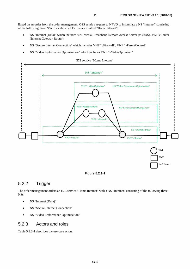
Based on an order from the order management, OSS sends a request to NFVO to instantiate a NS "Internet" consisting of the following three NSs to establish an E2E service called "Home Internet":
• NS "Internet (Data)" which includes VNF virtual Broadband Remote Access Server (vBRAS), VNF vRouter (Internet Gateway Router)
• NS "Secure Internet Connection" which includes VNF "vFirewall", VNF "vParentControl"
• NS "Video Performance Optimization" which includes VNF "vVideoOptimizer"
Figure 5.2.1-1
5.2.2 Trigger
The order management orders an E2E service "Home Internet" with a NS "Internet" consisting of the following three NSs:
• NS "Internet (Data)"
• NS "Secure Internet Connection"
• NS "Video Performance Optimization"
5.2.3 Actors and roles
Table 5.2.3-1 describes the use case actors.
ETSI
ETSI GR NFV-IFA 012 V3.1.1 (2018-10) 12
Table 5.2.3-1: Actors and roles
# Actors and roles
1 Operational Support Systems (OSS) E2E Service Fulfillment
2 NFVO
5.2.4 Pre-conditions
Table 5.2.4-1 describes the use case pre-conditions.
Table 5.2.4-1: Pre-conditions
# Pre-conditions Comment
1 Network Service Descriptor (NSD) for NS "Internet" is onboarded.
5.2.5 Post-conditions
Table 5.2.5-1 describes the use case post-conditions.
Table 5.2.5-1: Post-conditions
# Post-conditions Comment
1 The NS "Internet" has been successfully instantiated by NFVO. Afterwards OSS concatenated them with existing access service and Customer Premises Equipment (CPE) in legacy domain (it is out of scope of this use case).
2 The CSP provides an E2E service "Home Internet" which connects CPE, access service and NS "Internet" consisting of the following three NSs:
• NS "Internet (Data)". • NS "Secure Internet Connection". • NS "Video Performance Optimization".
5.2.6 Flow description
Table 5.2.6-1 describes the use case flow.

ETSI
ETSI GR NFV-IFA 012 V3.1.1 (2018-10) 13
Table 5.2.6-1: Base Flow
# Actor Action/Description
1 OSS E2E Service Fulfillment OSS derives from the service order the appropriate request concerning the NSs, ready to send to the NFVO for fulfillment.
2 OSS E2E Service Fulfillment -> NFVO The OSS sends an NS "Internet" instantiation request to the NFVO. Interface - Os-Ma-nfvo
3 NFVO Validate the NS instantiation request against the onboarded NSD. This activity verifies the NS request in relation to the corresponding NSD for consistency.
4 NFVO -> Virtual Network Function Manager (VNF Manager)
Request to instantiate the VNFs involved concerning the NS "Internet", and based on the following internal NSs in parallel:
• NS "Internet (Data)". • NS "Secure Internet Connection". • NS "Video Performance Optimization".
See note. Interface - Or-Vnfm
5 NFVO -> VIM Request to instantiate Virtual Links (VLs), which connect VNFs instances according to the NS "Internet" VNF-FG. Interface - Or-Vi
6 NFVO -> OSS E2E Service Fulfilment The NFVO will send a positive acknowledgment concerning the instantiation request for the NS "Internet" including the three nested NSs, if this was successful. Otherwise the NFVO will send a failure indication to the OSS. Interface - Os-Ma-nfvo / NS lifecycle management
NOTE: The sequential instantiation is another use case in this context.
5.3 NS monitoring in Broadband Network
5.3.1 Use case description
The main goal of this use case is to illustrate how NS lifecycle management and NS performance management related to the Os-Ma-nfvo reference point are used in the context of E2E Service Management.
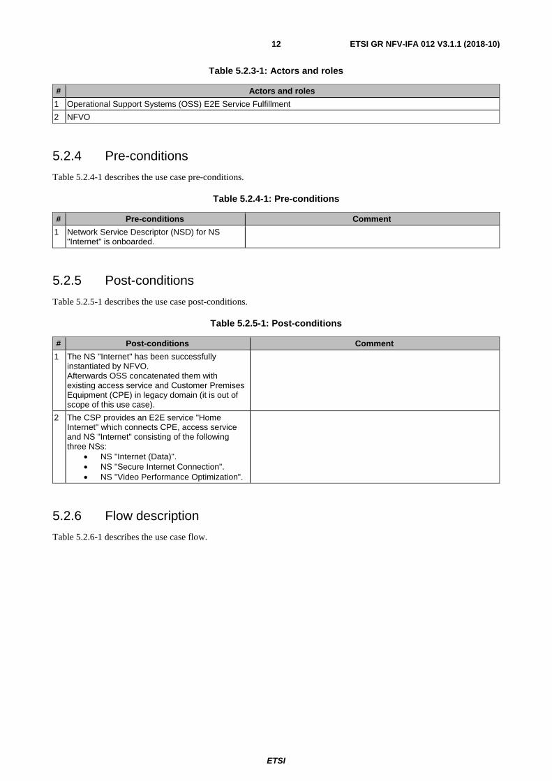
The OSS provides an E2E service monitoring and detects a SLA threshold violation concerning the E2E service "Home Internet".
Afterwards the OSS initiates immediately a scale out procedure for the NS "Internet" especially for the nested NS "Secure Internet Connection" to eliminate or minimize the performance degradation.
ETSI
ETSI GR NFV-IFA 012 V3.1.1 (2018-10) 14
Figure 5.3.1-1
5.3.2 Trigger
The increase of the HTTP traffic leads to an overload of the NS "Secure Internet Connection".
5.3.3 Actors and roles
Table 5.3.3-1 describes the use case actors.
Table 5.3.3-1: Actors and roles
# Actors and roles
1 OSS E2E Service Quality Management (SQM)
2 NFVO
5.3.4 Pre-conditions
Table 5.3.4-1 describes the use case pre-conditions.

ETSI
ETSI GR NFV-IFA 012 V3.1.1 (2018-10) 15
Table 5.3.4-1: Pre-conditions
# Pre-conditions Comment
1 Communications Service Provider (CSP) provides an E2E service "Home Internet" with a NS "Internet" consisting of the following three NSs:
• NS "Internet (Data)" (one vBRAS and one vRouter).
• NS "Secure Internet Connection" (one VNF "vFirewall" and one VNF "vParentControl").
• NS "Video Performance Optimization" (one VNF "vVideoOptimizer").
5.3.5 Post-conditions
Table 5.3.5-1 describes the use case post-conditions.
Table 5.3.5-1: Post-conditions
# Post-conditions Comment
1 The NS "Internet" especially the nested NS "Secure Internet Connection" has been scaled out.
The NS "Secure Internet Connection" has been scaled out.
5.3.6 Flow description
Table 5.3.6-1 describes the use case flow.

ETSI
ETSI GR NFV-IFA 012 V3.1.1 (2018-10) 16
Table 5.3.6-1: Base Flow
# Actor Action/Description
1 NFVO -> OSS E2E SQM Send performance information that the NFVO can collect from the NS "Internet" including the nested NSs. Interface - Os-Ma-nfvo / NS performance management
2 OSS E2E SQM The OSS evaluates the Key Performance Indicators (KPIs) and Key Quality Indicators (KQIs) for the E2E service including information from other sources outside of the NFV MANO and detects a Service Level Agreement (SLA) threshold violation for the NS "Secure Internet Connection".
3 OSS E2E SQM - > NFVO The OSS sends a NS scale out request for the NS " Secure Internet Connection" to the NFVO. Interface - Os-Ma-nfvo /
4 NFVO Validates the request. This activity verifies the request concerning consistency. Defines that the NS "Secure Internet Connection" needs to be scaled out.
5 NFVO - > VNFM Scale out request regarding VNF "vFirewall" and VNF "vParentControl" for the NS "Secure Internet Connection".
6 NFVO - > VIM The NFVO sends a request to VIM to change the resource (VNF Forwarding Graph (VNFFG) and VirtualLink (VL)) allocation and the interconnection setup. Interface - Or-Vi
7 VIM Modifies or creates a new inter connectivity between VNFs prescribed in the new flavor of the NS.
8 VIM -> NFVO Returns results of the creation and modification of the interconnections between VNFs. Interface - Or-Vi
9 NFVO -> OSS E2E SQM The NFVO will send a positive acknowledgment concerning the completeness of the scale out operation of the NS to the OSS, if the operation was successful. Otherwise the NFVO will send a failure indication to the OSS. Interface - Os-Ma-nfvo / NS lifecycle management
5.4 Notification about a lack of capacity during NS LCM operation
5.4.1 Use case description
The main goal of this use case is to illustrate the possibility to notify about lack of resource capacity during NS Lifecycle Management (LCM) operation.
This use case will end after OSS is triggered and will not show the "entire work flow" and considers any type of NSs also in relation to services on top of NSs.
5.4.2 Trigger
NFVO needs to perform a NS LCM operation.
5.4.3 Actors and roles
Table 5.4.3-1 describes the use case actors.
ETSI
ETSI GR NFV-IFA 012 V3.1.1 (2018-10) 17
Table 5.4.3-1: Actors and roles
# Actors and roles
1 OSS
2 NFVO
3 VIM
5.4.4 Pre-conditions
Table 5.4.4-1 describes the use case pre-conditions.
Table 5.4.4-1: Pre-conditions
# Pre-conditions Comment
1 A NS should be initiated or another LCM operation should be performed on it.
5.4.5 Post-conditions
Table 5.4.5-1 describes the use case post-conditions.
Table 5.4.5-1: Post-conditions
# Post-conditions Comment
1 OSS is aware of the lack of resource capacity.
5.4.6 Flow description
Table 5.4.6-1 describes the use case flow.
Table 5.4.6-1: Base Flow
# Actor Action/Description
1 NFVO NFVO determines a need for a NS LCM operation.
2 NFVO -> VIM NFVO checks with VIM concerning the availability and the capacity of virtualised resources that support the appropriate VNF instances, and the VLs of the VNFFG that connect them.
3 VIM -> NFVO VIM responses to NFVO and informs that "No sufficient resource capacity is available". See note 1.
4 NFVO -> OSS NFVO sends a notification to the OSS about the lack of resource capacity concerning a NS LCM operation. See note 2.
NOTE 1: It is a specific reporting of the lack of virtualised resource capacity with root cause of unavailable physical capacity.
NOTE 2: In case of OSS initiates the LCM operation, the result can be given back without a notification.
5.5 Virtual Converged IP Messaging NS deployment
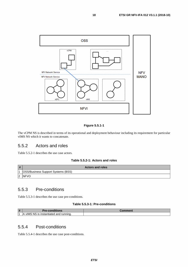
5.5.1 Use case description
This use case describes deploying a virtualised CPM (Converged IP Messaging) NS concatenating vIP Multimedia Subsystem (vIMS) NS. That implies that the virtualised CPM concatenates the underlying vIMS.
ETSI
ETSI GR NFV-IFA 012 V3.1.1 (2018-10) 18
Figure 5.5.1-1
The vCPM NS is described in terms of its operational and deployment behaviour including its requirement for particular vIMS NS which it wants to concatenate.
5.5.2 Actors and roles
Table 5.5.2-1 describes the use case actors.
Table 5.5.2-1: Actors and roles
# Actors and roles
1 OSS/Business Support Systems (BSS)
2 NFVO
5.5.3 Pre-conditions
Table 5.5.3-1 describes the use case pre-conditions.
Table 5.5.3-1: Pre-conditions
# Pre-conditions Comment 1 A vIMS NS is instantiated and running.
5.5.4 Post-conditions
Table 5.5.4-1 describes the use case post-conditions.

ETSI
ETSI GR NFV-IFA 012 V3.1.1 (2018-10) 19
Table 5.5.4-1: Post-conditions
# Post-conditions Comment 1 A vCPM NS is deployed by concatenating an
existing vIMS NS
5.5.5 Flow description
Table 5.5.5-1 describes the use case flow.
Table 5.5.5-1: Base Flow
# Actor Action/Description 1 OSS/BSS OSS/BSS decides to deploy a vCPM NS concatenating on a
vIMS NS which is already deployed in the network. 2 OSS/BSS -> NFVO OSS/BSS sends a Create NS Identifier request to the NFVO
including the nsdId for the vCPM NSD. 3 NFVO -> OSS/BSS The NFVO returns an NS Identifier to the BSS/OSS. 4 OSS/BSS -> NFVO A vCPM NS instantiation request is sent by the OSS/BSS to
NFVO, including the NS Identifier of the newly created vCPM NS. Interface - Os-Ma-nfvo
5 NFVO NFVO identifies the NSD of the vCPM NS based on the NSD identification received from the instantiation request. The existing vIMS NS instance is identified based on the dependency information described in the identified NSD of vCPM. The dependency information to identify the existing vIMS NS can be in terms of its NSD, instance ID and external connection point exposed. See note.
6 NFVO -> VNF Manager The vCPM NS is instantiated by instantiating all its components and the connection between them. Interface - Or-Vnfm
7 NFVO -> VIM The connection with the existing vIMS NS is established based on the information identified about the existing vIMS NS including service instance and the connection point information. Interface - Or-Vi
8 NFVO -> OSS/BSS The vCPM NS deployment gets confirmed. Interface - Os-Ma-nfvo / NS lifecycle management
NOTE: In case of instance ID of vIMS NS is included in the dependency information, OSS/BSS can query the instance information of vIMS NS before sending the instantiation request.
5.6 OSS requests an NS instance update from the NFVO
5.6.1 Use case description
A customer will change his Service Level Agreement (SLA) for an NS and make a request to apply it to the NS. The OSS/BSS identifies the request from the customer and finds out the appropriate running instance of the NS which has to be updated.
The OSS/BSS will trigger a request for an update of the dedicated NS with the necessary information to the NFVO.
The NFVO will handle this update with success or with a failure response.
There are several scenarios that will require such an update. This use case is focused on a SLA change in connection with a running NS.
5.6.2 Actors and roles
Table 5.6.2-1 describes the use case actors.

ETSI
ETSI GR NFV-IFA 012 V3.1.1 (2018-10) 20
Table 5.6.2-1: Actors and roles
# Actors and roles
1 OSS/BSS
2 NFVO
5.6.3 Pre-conditions
Table 5.6.3-1 describes the use case pre-conditions.
Table 5.6.3-1: Pre-conditions
# Pre-conditions Comment 1 The OSS/BSS has identified a request to
make a change to an instantiated NS based on an SLA change request from a customer concerning a running NS.
2 The OSS/BSS is aware of the instantiated NS that are being updated and can identify this NS instance.
3 In the OSS/BSS there is a relationship between the customer and the dedicated running NS instance.
4 It is assumed that several SLA types are pre-defined and are valid to apply to the dedicated NS (e.g. bronze, silver and gold).
There are several variants to change the SLA. In this use case it is assumed that several SLA types (e.g. bronze, silver and gold) are pre-defined in the corresponding NSD. There are two categories of KPIs available. One category defines the service running behaviour, for example provided bandwidth and guaranteed latency . The other category defines the operational aspects of the service, e.g. fault clearance time after a failure occurs.
5.6.4 Post-conditions
Table 5.6.4-1 describes the use case post-conditions.
Table 5.6.4-1: Post-conditions
# Post-conditions Comment 1 The dedicated running NS has been updated
based on the request.
5.6.5 Flow description
Table 5.6.5-1 describes the use case flow.
ETSI
ETSI GR NFV-IFA 012 V3.1.1 (2018-10) 21
Table 5.6.5-1: Base Flow
# Actor Action/Description 1 OSS/BSS The OSS/BSS identifies that a running NS instance needs to be
updated. 2 OSS/BSS -> NFVO The OSS/BSS sends an NS Update request to the NFVO with
the necessary information, this means configuration information about the requested SLA type (e.g. a change from silver to gold).
3 NFVO The NFVO makes a validation check about this request including the information delivered and initiates a change to the NS instance.
4 NFVO The NFVO requests a change of the dedicated NS in connection with the configuration change of the SLA type (e.g. from silver to gold), if the validation check is successful. Otherwise it will give a failure response with the error cause to the OSS/BSS.
5 NFVO -> OSS/BSS The NFVO returns a successful response with the corresponding NS instance ID, if the requested operation was successful. Otherwise the OSS receives a failure response with the error cause from the NFVO.
5.7 On-board NSD from OSS/BSS
5.7.1 Use case description
There are numerous scenarios where BSS/OSS applications require information about the NSDs and VNF Packages that have been on-boarded in the NFVO. NSDs, VNF Packages, and the VNF Descriptors (VNFDs) contained within may be used for many purposes within the BSS/OSS, including Procurement, Strategic Planning, Infrastructure Lifecycle Management, Product Lifecycle Management, Fulfilment, Provisioning, Assurance, and/or Billing.
Product Catalog is one of these BSS/OSS applications requiring interconnectedness with the NFV Orchestrator over the Os-Ma interface. In order to construct product specifications that are based on at least one NS that is on-boarded within the NFV ecosystem, the Product Catalog needs to have an understanding of the NSDs that are currently on-boarded within the NFV ecosystem. In order to be able to define new NSs to use within product specifications, the Product Catalog needs to be aware of the VNF Packages that are currently on-boarded in the NFV ecosystem and it needs to be able to on-board new NSDs within the NFV ecosystem in order to prepare the NFVO to be ready to accept instantiation requests for the new NSD when a product is ordered.
This use case describes a scenario where the BSS/OSS Product Catalog uses the NFVO synchronization and NSD creation interfaces to create a representation of a new commercial product (based on one or more NSs).
NFVO synchronization with the Product Catalog can occur in 2 different ways: with either the BSS/OSS querying the NFVO for details about the on-boarded NSDs and VNF Packages, or the BSS/OSS being notified automatically about successful NSD and VNF Package on-boarding events. These alternatives are described below as sub-use cases. If the notification mechanism is being used - the expectation is that the Product Catalog has the latest information about current on-boarded NSDs and VNF Packages. If however the notification mechanism is not in place - then prior to defining a new product specification, the Product Catalog will perform a query to synchronize with the NFV ecosystem especially with the NFVO.
As a result of synchronization - the Product Catalog will contain representations of the NSDs and VNF Packages that are on-boarded in the NFVO. These will most likely be represented as Resource Facing Services (RFS) or Resources in the Product Catalog. The Product Catalog can then be used to define higher level commercial entities such as Customer Facing Services (CFS) and Products that build upon these RFSs and Resources. Note that at this level it is possible to create Products and CFSs that are based on multiple NSs or could include Physical Network Functions (PNFs) allowing the definition of hybrid PNF/VNF based Products. Note: The representation of the NSD and VNF in the OSS/BSS will be a subset of the information contained about the NSD and VNF within the NFVO. Each OSS application will decide how much or how little of the complete NSD/VNF data it requires and will persist only what is needed for that application.
ETSI
ETSI GR NFV-IFA 012 V3.1.1 (2018-10) 22
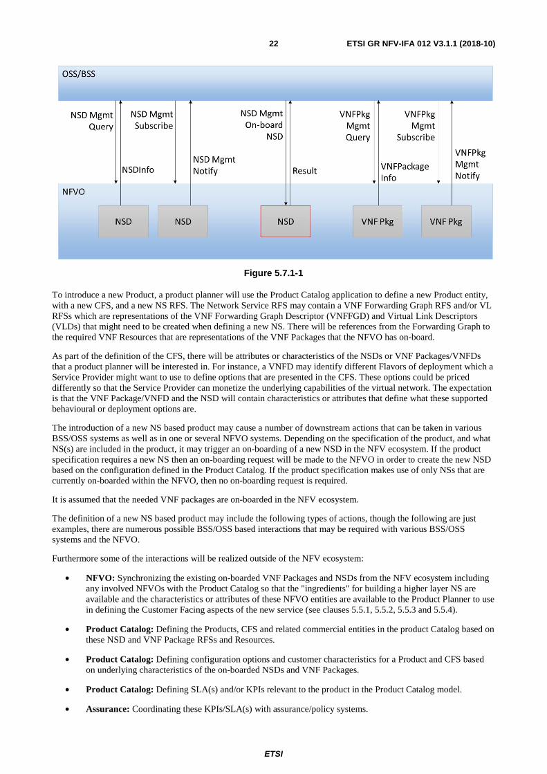
Figure 5.7.1-1
To introduce a new Product, a product planner will use the Product Catalog application to define a new Product entity, with a new CFS, and a new NS RFS. The Network Service RFS may contain a VNF Forwarding Graph RFS and/or VL RFSs which are representations of the VNF Forwarding Graph Descriptor (VNFFGD) and Virtual Link Descriptors (VLDs) that might need to be created when defining a new NS. There will be references from the Forwarding Graph to the required VNF Resources that are representations of the VNF Packages that the NFVO has on-board.
As part of the definition of the CFS, there will be attributes or characteristics of the NSDs or VNF Packages/VNFDs that a product planner will be interested in. For instance, a VNFD may identify different Flavors of deployment which a Service Provider might want to use to define options that are presented in the CFS. These options could be priced differently so that the Service Provider can monetize the underlying capabilities of the virtual network. The expectation is that the VNF Package/VNFD and the NSD will contain characteristics or attributes that define what these supported behavioural or deployment options are.
The introduction of a new NS based product may cause a number of downstream actions that can be taken in various BSS/OSS systems as well as in one or several NFVO systems. Depending on the specification of the product, and what NS(s) are included in the product, it may trigger an on-boarding of a new NSD in the NFV ecosystem. If the product specification requires a new NS then an on-boarding request will be made to the NFVO in order to create the new NSD based on the configuration defined in the Product Catalog. If the product specification makes use of only NSs that are currently on-boarded within the NFVO, then no on-boarding request is required.
It is assumed that the needed VNF packages are on-boarded in the NFV ecosystem.
The definition of a new NS based product may include the following types of actions, though the following are just examples, there are numerous possible BSS/OSS based interactions that may be required with various BSS/OSS systems and the NFVO.
Furthermore some of the interactions will be realized outside of the NFV ecosystem:
• NFVO: Synchronizing the existing on-boarded VNF Packages and NSDs from the NFV ecosystem including any involved NFVOs with the Product Catalog so that the "ingredients" for building a higher layer NS are available and the characteristics or attributes of these NFVO entities are available to the Product Planner to use in defining the Customer Facing aspects of the new service (see clauses 5.5.1, 5.5.2, 5.5.3 and 5.5.4).
• Product Catalog: Defining the Products, CFS and related commercial entities in the product Catalog based on these NSD and VNF Package RFSs and Resources.
• Product Catalog: Defining configuration options and customer characteristics for a Product and CFS based on underlying characteristics of the on-boarded NSDs and VNF Packages.
• Product Catalog: Defining SLA(s) and/or KPIs relevant to the product in the Product Catalog model.
• Assurance: Coordinating these KPIs/SLA(s) with assurance/policy systems.

ETSI
ETSI GR NFV-IFA 012 V3.1.1 (2018-10) 23
• Billing: Coordinating the commercial elements of the product and SLA with billing systems.
• NFVO: Defining settings in the NSD (e.g. flavours and Quality of Service (QoS)) to support the possible KPIs/SLA(s) defined in the Product Catalog.
• NFVO: If a new NS is defined in the product specification on-boarding the new NSD definition in the NFVO to make the NS available during product ordering/provisioning/instantiation.
If an on-boarding request is required, the BSS/OSS will transfer a complete NSD including a list of VNFD Ids for the VNFs being utilized and may include VLDs, and/or a VNFFGD to be on-boarded. The NFVO will on-board the provided NSD into the NFV ecosystem.
5.7.2 Actors and roles
Table 5.7.2-1 describes the use case actors.
Table 5.7.2-1: Actors and roles
# Actors and roles
1 BSS/OSS
2 NFVO
5.7.3 Pre-conditions
Table 5.7.3-1 describes the use case pre-conditions.
Table 5.7.3-1: Pre-conditions
# Pre-conditions Comment 1 One or more VNF Packages are on-boarded
within the NFV ecosystem. The VNF Package(s) need to be on-boarded into the NFV ecosystem, they do not need to be instantiated.
5.7.4 Post-conditions
Table 5.7.4-1 describes the use case post-conditions.
Table 5.7.4-1: Post-conditions
# Post-conditions Comment 1 In the BSS/OSS environment (Product
Catalog) has been defined a new product (based on at least one NS).
2 The NFVO has on-boarded all of the NSDs that are used within the product specification.
3 Other BSS/OSS (billing, assurance) systems are aware of the new product.
5.7.5 Flow description
Table 5.7.5-1 describes the use case flow.

ETSI
ETSI GR NFV-IFA 012 V3.1.1 (2018-10) 24
Table 5.7.5-1: Base Flow
# Actor Action/Description
1 BSS/OSS -> NFVO If the BSS/OSS is not using Notification events for on-boarding of VNF Packages or NSDs in connection with the BSS/OSS Product catalog then the BSS/OSS will need to query the NFVO to synchronize the current list of on-boarded NSDs and VNF Packages. See sub-use cases 5.5.1 and 5.5.3. If notification events are being received automatically from the BSS/OSS delivered by the NFVO after a successful on-boarding of a NSD or VNF then it is assumed that the current lists of on-boarded NSDs and VNF Packages are up-to-date. See sub-use cases 5.6.2 and 5.6.4.
2 BSS/OSS In the BSS/OSS Product Catalog there will be a new product specification defined that may include one or more currently on-boarded NSDs, the product specification may include a definition for a new NSD making use of currently on-boarded VNF Package(s) and in this case will specify a complete valid NSD as described in ETSI GS NFV-IFA 014 [i.7], clause 6.2.
3 BSS/OSS As part of the product specification, Commercial Facing Service (CFS) characteristics are defined that will be represented by aspects of the underlying NSDs and VNF Packages. These CFS characteristics are used at order capture time to set options that may be supported when an NSD and the VNFs it requires are instantiated. This could include e.g. the definition of supported SLAs that are based on options that are defined in the NSDs or VNFPackages (like NS Deployment Flavor or VNF Flavor).
4 BSS/OSS -> NFVO If a new NSD is required by the product specification, an "On-board NSD" request with the necessary parameter values is sent by the BSS/OSS to NFVO. Interface - Os-Ma-nfvo/ NSD management
5 NFVO If a new NSD is requested, the NFVO on-boards the provided NSD. The NFVO will validate the NSD and will also on-board any VNFFGDs or VLDs that are specified in the NSD.
6 NFVO -> BSS/OSS If a new NSD is requested, the NFVO returns a success or failure response indicating that the on-boarding activity completed successfully or could not be completed. If successful, the response should include the corresponding NSD ID.
5.8 BSS/OSS Queries VNFs
5.8.1 Use case Description
This use case describes a scenario where the BSS/OSS systems needs to be aware of the VNFs that are on-boarded within the NFV ecosystem. The BSS/OSS system will send a query for the VNFD to obtain these entities. The NFVO will respond with a list of the requested entities.
5.8.2 Actors and roles
Table 5.8.2-1 describes the use case actors.
Table 5.8.2-1: Actors and roles
# Actors and roles
1 BSS/OSS
2 NFVO

ETSI
ETSI GR NFV-IFA 012 V3.1.1 (2018-10) 25
5.8.3 Pre-conditions
Table 5.8.3-1 describes the use case pre-conditions.
Table 5.8.3-1: Pre-conditions
# Pre-conditions Comment 1 One or more VNFs are on-boarded within the
NFVO ecosystem. The VNF(s) need to be on-boarded in the NFVO ecosystem, they do not need to be instantiated.
5.8.4 Post-conditions
Table 5.8.4-1 describes the use case post-conditions.
Table 5.8.4-1: Post-conditions
# Post-conditions Comment 1 The BSS/OSS system has synchronized its
internal DB with the VNF Packages that are on-boarded in the NFV ecosystem.
5.8.5 Flow description
Table 5.8.5-1 describes the use case flow.
Table 5.8.5-1: Base Flow
# Actor Action/Description
1 BSS/OSS BSS/OSS requires information about VNF Packages that are on-boarded within the NFV ecosystem. The BSS/OSS can define a list of target vnfPackageIds or VNFIds that it would like to retrieve.
2 BSS/OSS -> NFVO A "Query VNF Packages" request is sent by the BSS/OSS to NFVO. Interface - Os-Ma-nfvo/ VNF Package Management
3 NFVO -> BSS/OSS The NFVO returns a response to BSS/OSS that contains a list of VNFPackageInfo elements. If the BSS/OSS specified a list of target vnfPackageIds or VNFIds in the request, the returned list will contain only the vnfPackageInfo elements specified by the requested vnfPackageIds or VNFIds. If no target vnfPackageIds or VNFIds were specified in the request, all vnfPackageInfoelements of the on-boarded VNF Packages will be returned (default value). Interface - Os-Ma-nfvo / VNF Package Management
5.9 BSS/OSS is notified of VNF Package on-boarding
5.9.1 Use case Description
When a VNF Package is on-boarded within the NFVO, a notification is sent to the BSS/OSS to indicate that the VNF Package has been onboarded.
5.9.2 Actors and roles
Table 5.9.2-1 describes the use case actors.

ETSI
ETSI GR NFV-IFA 012 V3.1.1 (2018-10) 26
Table 5.9.2-1: Actors and roles
# Actors and roles
1 NVFO
2 BSS/OSS
3 Messaging mechanism for notifications provided by the NFVO
5.9.3 Pre-conditions
Table 5.9.3-1 describes the use case pre-conditions.
Table 5.9.3-1: Pre-conditions
# Pre-conditions Comment 1 NFVO is installed and provided a messaging
mechanism for notifications.
2 BSS/OSS applications have been registered to receive notifications from the NFVO concerning the VNF Package on-boarding.
5.9.4 Post-conditions
Table 5.9.4-1 describes the use case post-conditions.
Table 5.9.4-1: Post-conditions
# Post-conditions Comment 1 The BSS/OSS system has synchronized its
internal Database (DB) with the VNF Package that the NFVO has just on-boarded.
5.9.5 Flow description
Table 5.9.5-1 describes the use case flow.

ETSI
ETSI GR NFV-IFA 012 V3.1.1 (2018-10) 27
Table 5.9.5-1: Base Flow
# Actor Action/Description
1 NFVO A VNF Packages is on-boarded into the NFV ecosystem. The NFVO determines whether notifications should be generated based on the registration for notifications.
2 NFVO -> Generation of notifications The NFVO generates one or more notifications that contain the vnfPackageId for the newly on-boarded VNF Package.
3 NFVO -> BSS/OSS The NFVO sends these notifications to the corresponding registered BSS/OSS applications.
4 BSS/OSS The BSS/OSS applications receive the notification of the VNF Package on-boarding event and retrieves the vnfPackageId from the notification.
5 BSS/OSS -> NFVO A "Query VNF Packages" request is sent by the BSS/OSS to NFVO containing the vnfPackageId received in the notification Interface - Os-Ma-nfvo/ VNF Package Management
6 NFVO-> BSS/OSS The NFVO returns a response to BSS/OSS that contains the requested VNFPackageInfo element. Interface - Os-Ma-nfvo / VNF Package Management
7 BSS/OSS The BSS/OSS application updates its internal database to include the information relevant to the newly on-boarded VNF Package.
5.10 BSS/OSS Queries NSDs
5.10.1 Use case Description
This use case describes a scenario where the BSS/OSS systems needs to be aware of the NSDs that are on-boarded within the NFV ecosystem. The BSS/OSS system will send a query for the NSD to obtain these entities. The NFVO will respond with a list of the requested entities.
5.10.2 Actors and roles
Table 5.10.2-1 describes the use case actors.
Table 5.10.2-1: Actors and roles
# Actors and roles
1 BSS/OSS
2 NFVO
5.10.3 Pre-conditions
Table 5.10.3-1 describes the use case pre-conditions.
Table 5.10.3-1: Pre-conditions
# Pre-conditions Comment 1 One or more NSDs are on-boarded within the
NFV ecosystem. The NSD(s) need to be on-boarded within the NFV ecosystem, they do not need to be instantiated.
5.10.4 Post-conditions
Table 5.10.4-1 describes the use case post-conditions.
ETSI
ETSI GR NFV-IFA 012 V3.1.1 (2018-10) 28
Table 5.10.4-1: Post-conditions
# Post-conditions Comment 1 The BSS/OSS system has a list of NSDs that
is synchronized with the NSDs that are on-boarded in the NFV ecosystem.
5.10.5 Flow description
Table 5.10.5-1 describes the use case flow.
Table 5.10.5-1: Base Flow
# Actor Action/Description
1 BSS/OSS BSS/OSS requires information about NSDs that are on-boarded within the NFV ecosystem. The BSS/OSS can define a list of target NSDIds that it would like to retrieve.
2 BSS/OSS -> NFVO A "Query NSD" request is sent by the BSS/OSS to NFVO. Interface - Os-Ma-nfvo/ NSD management
3 NFVO -> BSS/OSS The NFVO returns a response to the BSS/OSS that contains a list of NSDInfo elements. If the BSS/OSS specified a list of target NSDIds, the returned list will contain only the NSDInfo elements for the NSDs specified by the requested NSDIds. If no list of target NSDIds is specified, NSDInfo elements for all on-boarded NSDs will be returned. Interface - Os-Ma-nfvo / NSD management
5.11 NFVO updates BSS/OSS with NSD information after NSD on-boarding
5.11.1 Use case Description
This use case describes a scenario where the BSS/OSS applications are notified as a result of the on-boarding of one or more NSDs within the NFV ecosystem. Before that the BSS/OSS applications have been subscribed to a messaging mechanism for notifications provided by the NFVO. After this the NFVO will send a notification to inform the registered BSS/OSS parties about the successful NSD on-boarding event(s).
5.11.2 Actors and roles
Table 5.11.2-1 describes the use case actors.
Table 5.11.2-1: Actors and roles
# Actors and roles
1 NVFO
2 BSS/OSS
3 Messaging mechanism for notifications provided by the NFVO
5.11.3 Pre-conditions
Table 5.11.3-1 describes the use case pre-conditions.
ETSI
ETSI GR NFV-IFA 012 V3.1.1 (2018-10) 29
Table 5.11.3-1: Pre-conditions
# Pre-conditions Comment 1 NFVO is installed and provide a messaging
mechanism for notifications.
2 BSS/OSS applications have been registered to receive notifications from the NFVO regarding the NS on-boarding.
5.11.4 Post-conditions
Table 5.11.4-1 describes the use case post-conditions.
Table 5.11.4-1: Post-conditions
# Post-conditions Comment 1 The BSS/OSS system has a list of NSDs that
is synchronized with the NSDs that are on-boarded in the NFV ecosystem.
5.11.5 Flow description
Table 5.11.5-1 describes the use case flow.
Table 5.11.5-1: Base Flow
# Actor Action/Description
1 NFVO A NSD is on-boarded within the NFV ecosystem. The NFVO determines whether notifications should be generated based on the registration for notifications.
2 NFVO -> Generation of notifications The NFVO generates a notification that contain the NSDId for the newly on-boarded NSD.
3 NFVO -> BSS/OSS The NFVO sends these notifications to the corresponding registered BSS/OSS applications.
4 BSS/OSS The BSS/OSS applications receive the notifications of NSD on-boarding event(s) and retrieve the NSDId from the notifications.
5 BSS/OSS->NFVO A "Query NSD" request is sent by the BSS/OSS to NFVO containing the NSDId received in the notification. Interface - Os-Ma-nfvo/ NSD management
6 NFVO->BSS/OSS The NFVO returns a response to the BSS/OSS that contains the NSDInfo elements for the specified NSDId. Interface - Os-Ma-nfvo / NSD management
7 BSS/OSS The BSS/OSS application updates its internal database to include the information relevant to the newly on-boarded NSD.
5.12 OSS requests a QoS update in connection with an NSD
5.12.1 Use case Description
A user will change an SLA value concerning the SLA type gold for an NS and therefore make a request to change the low latency value. The OSS/BSS notices the request from the user and finds out the appropriate NSD which has to be updated in connection with the changed SLA value.
The OSS/BSS will trigger a request for an update of the identified NSD with the necessary information to the NFVO.
The NFVO will handle this update with success or with a failure response.

ETSI
ETSI GR NFV-IFA 012 V3.1.1 (2018-10) 30
There are several scenarios that will require such an update. This use case is focused on an explicit change of a value of an SLA in connection with an NSD/NS.
5.12.2 Trigger
The OSS/BSS will make a request for an update of the identified NSD towards the NFVO.
5.12.3 Actors and roles
Table 5.12.3-1 describes the use case actors.
Table 5.12.3-1: Actors and roles
# Actors and roles
1 OSS/BSS
2 NFVO
5.12.4 Pre-conditions
Table 5.12.4-1 describes the use case pre-conditions.
Table 5.12.4-1: Pre-conditions
# Pre-conditions Comment 1 The OSS/BSS has identified a request to
make a change to an NSD based on an SLA type value change request from an user concerning an NS.
2 The OSS/BSS is aware of the NS and the corresponding NSD that are being updated and can identify this NSD.
5.12.5 Post-conditions
Table 5.12.5-1 describes the use case post-conditions.
Table 5.12.5-1: Post-conditions
# Post-conditions Comment 1 A new version of an NSD with the changed
SLA type gold has been on-boarded. In addition a new NS version has been instantiated using the new NSD version or the corresponding active NS instance(s) have been updated based on this new NSD.
5.12.6 Flow description
Table 5.12.6-1 describes the use case flow.

ETSI
ETSI GR NFV-IFA 012 V3.1.1 (2018-10) 31
Table 5.12.6-1: Base Flow
# Actor Action/Description
1 OSS/BSS The OSS/BSS identifies that a value of the SLA type gold pre-defined in an NSD needs to be changed.
2 OSS/BSS -> NFVO The OSS/BSS queries the NFVO to get the identifier of the NSD of the corresponding active NS.
3 OSS/BSS -> NFVO If the OSS/BSS receives the NSD ID then the OSS/BSS will send a query request with the NSD ID to get the attribute values of this NSD. Otherwise the OSS/BSS receives a failure notification.
4 OSS/BSS -> NFVO The OSS/BSS sends a request to the NFVO for updating the NSD to the version with the modified values of the NSD including the new latency value which should be set in the qos attribute of the VldFlavour information element of the NSVirtualLinkDesc information element.
5 NFVO The NFVO makes a validation check about this request including the information delivered. If the check is successful the NFVO initiates the update of the NSD with the new NSD version provided.
6 NFVO -> OSS/BSS The NFVO returns a successful response with the corresponding NSD ID including the new version value, if the requested operation was successful. Otherwise the OSS/BSS receives a failure response with the error cause from the NFVO.
7 OSS/BSS -> NFVO The OSS/BSS will either request the instantiation of one or more new NSs related to this new NSD or to update the corresponding active NS instance(s) based on this new NSD as another option.
8 NFVO -> OSS/BSS The NFVO returns a successful response with the corresponding NS ID(s) from the new NS(s) including the new version value or from the corresponding active NS instance(s) - depending of the option requested - , if the requested operation was successful. Otherwise the OSS/BSS receives a failure response with the error cause from the NFVO.
5.13 Instantiate Multiple Concatenated NSs
5.13.1 Use case Description
5.13.1.1 Introduction
This use case describes a scenario where an OSS/BSS application receives a request to instantiate a product or end-to-end service that is based on multiple underlying NSs. The OSS/BSS application will instantiate the NSs required in order. Each NS instantiation request will identify the NSD to be used for the NS. The OSS/BSS will have an awareness of the nsdIds that are on-board on any of the NFVOs involved in the use case. The NS instantiation requests will define the nsdId that is to be used to instantiate each of the NSs.

ETSI
ETSI GR NFV-IFA 012 V3.1.1 (2018-10) 32
Figure 5.13.1-1
The OSS/BSS application will receive a status response for each NS instantiation request made to the NFVO, it is up to the OSS/BSS to determine whether a failure results in rolling-back of all associated NS instances or if a partial success status is acceptable. With concatenated NSs, it is assumed that the NFVO has no understanding that any of the NSs are related to each other. It is the responsibility of the OSS to maintain these relationships in whatever form it sees fit.
If a partial success occurs, and rollback is not executed, then the OSS/BSS application may send subsequent commands at a later time to instantiate the NSs that failed, which if successful will complete the end-to-end service instantiation.
The OSS has the responsibility to ensure that the SAPs of each NS are connected either to each other, or to physical network connections that are created for the end-to-end service. Note that in the case of there being a physical network connection used in this manner - there are no representations of the PNFs related to this connection in any of the NSs that are instantiated. The OSS is also responsible for the determination of the order in which virtual NSs and physical network connections are established.
Figure 5.13.1-2
5.13.1.2 Parallel vs Sequential NS Instantiation requests
The OSS/BSS can decide to send initiation requests for the NSs in parallel or sequentially. The decision will consider dependencies between the NSs being instantiated. It is up to the OSS/BSS to understand these dependencies and make the decision as to whether the requests can be sent in parallel or not, and what order the requests need to be sent if they are sent sequentially. Since the NSs instantiation requests being received by the NFVO are independent, the expectation is that either sequential or parallel requests can be made by the consumer (the OSS/BSS).
5.13.1.3 NS instantiation requests to different NFVOs
If the end-to-end service requires the use of NSs that are on-board in separate NFVOs then the use case essentially stays the same. The OSS/BSS is responsible for identifying the NFVO to which a NS instantiation request is sent and for coordinating the connectivity between the instantiated NSs, either a physical network connection or directly connecting the SAP of one NS to the SAP of another NS. The OSS/BSS is required to maintain the end-to-end service status and keep track of NS instantiation responses from any NFVOs that requests have been made to.
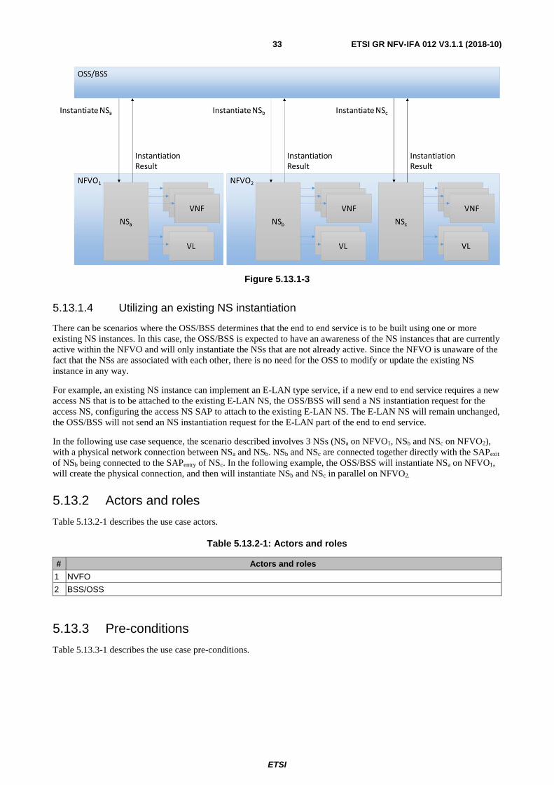
ETSI
ETSI GR NFV-IFA 012 V3.1.1 (2018-10) 33
Figure 5.13.1-3
5.13.1.4 Utilizing an existing NS instantiation
There can be scenarios where the OSS/BSS determines that the end to end service is to be built using one or more existing NS instances. In this case, the OSS/BSS is expected to have an awareness of the NS instances that are currently active within the NFVO and will only instantiate the NSs that are not already active. Since the NFVO is unaware of the fact that the NSs are associated with each other, there is no need for the OSS to modify or update the existing NS instance in any way.
For example, an existing NS instance can implement an E-LAN type service, if a new end to end service requires a new access NS that is to be attached to the existing E-LAN NS, the OSS/BSS will send a NS instantiation request for the access NS, configuring the access NS SAP to attach to the existing E-LAN NS. The E-LAN NS will remain unchanged, the OSS/BSS will not send an NS instantiation request for the E-LAN part of the end to end service.
In the following use case sequence, the scenario described involves 3 NSs (NSa on NFVO1, NSb and NSc on NFVO2), with a physical network connection between NSa and NSb. NSb and NSc are connected together directly with the SAPexit of NSb being connected to the SAPentry of NSc. In the following example, the OSS/BSS will instantiate NSa on NFVO1, will create the physical connection, and then will instantiate NSb and NSc in parallel on NFVO2.
5.13.2 Actors and roles
Table 5.13.2-1 describes the use case actors.
Table 5.13.2-1: Actors and roles
# Actors and roles
1 NVFO
2 BSS/OSS
5.13.3 Pre-conditions
Table 5.13.3-1 describes the use case pre-conditions.

ETSI
ETSI GR NFV-IFA 012 V3.1.1 (2018-10) 34
Table 5.13.3-1: Pre-conditions
# Pre-conditions Comment 1 NSDs are on-board in the NFVO for each NS
to be instantiated. NSa on-boarded on NFVO1. NSb and NSc on-boarded on NFVO2.
2 The OSS has synchronized with the NFVO and is aware of the nsdIds for all the NSDs that are on-board.
5.13.4 Post-conditions
Table 5.13.4-1 describes the use case post-conditions.
Table 5.13.4-1: Post-conditions
# Post-conditions Comment 1 Multiple NS instances are created in the
NFVO and end-to-end service is active.
5.13.5 Flow description
Table 5.13.5-1 describes the use case flow.

ETSI
ETSI GR NFV-IFA 012 V3.1.1 (2018-10) 35
Table 5.13.5-1: Base Flow
# Actor Action/Description
1 OSS/BSS Request received for end to end service containing multiple virtual NSs.
2 OSS/BSSNFVO OSS/BSS determines the NFVO that is to be targeted for the NS and sends a Create NS Identifier request for NSa on NFVO1
specifying the nsdId for NSDa.
3 NFVO->OSS/BSS NFVO1 responds with an NS Identifier for NSa.
4 OSS/BSS NFVO OSS/BSS sends an NS Instantiate request to NFVO1 for NSa
using the NS Identifier for NSa.
5 NFVO OSS/BSS Result of NS instantiation of NSa on NFVO1.
6 NFVO OSS/BSS NFVO1 sends the start lifecycle change notification for the NS instantiation for NSa to the OSS/BSS.
7 NFVO OSS/BSS NFVO1 sends the result lifecycle change notification for the NS instantiation for NSa indicating success to the OSS/BSS.
8 OSS/BSS Configure physical connection to connect NSa and NSb.
9 OSS/BSSNFVO OSS/BSS determines the NFVO that is to be targeted for the NS and sends a Create NS Identifier request for NSb and NSc in parallel to NFVO2 specifying the nsdIds for NSDb and NSDc.
10 NFVO OSS/BSS NFVO2 responds with an NS Identifier for NSb. See note.
11 OSS/BSS NFVO OSS/BSS sends an NS Instantiate request to NFVO2 for NSb
using the NS Identifier for NSb.
12 NFVO OSS/BSS Result of NS instantiations for NSb is returned.
13 OSS/BSS NFVO OSS/BSS sends an NS Instantiate request to NFVO2 for NSc
using the NS Identifier for NSc.
14 NFVO OSS/BSS Result of NS instantiations for NSc is returned.
15 NFVO OSS/BSS NFVO2 sends the start lifecycle change notification for the NS instantiation for NSb to the OSS/BSS.
16 NFVO OSS/BSS NFVO2 sends the start lifecycle change notification for the NS instantiation for NSc to the OSS/BSS.
17 NFVO OSS/BSS NFVO2 sends the result lifecycle change notification for the NS instantiation for NSb indicating success to the OSS/BSS.
18 NFVO OSS/BSS NFVO2 sends the result lifecycle change notification for the NS instantiation for NSc indicating success to the OSS/BSS.
NOTE: The order in which the NS Identifiers for NSb and NSc are returned is non-deterministic since the requests were sent in parallel.
5.14 Use Case for OSS/BSS instantiation of hybrid PNF/VNF NS
5.14.1 Use case Description
This use case describes a scenario where an OSS/BSS application makes a request to the NFVO to instantiate a specific NS that has a NSD already on-boarded in the NFV ecosystem. The NSD in this use case refers to both a PNF and a VNF. The use case describes how the OSS/BSS application coordinates the instantiation of both the NS within the NFVO and the physical network that is associated with the PNF which is referenced in the NSD.
NOTE: The description of the instantiation of the physical network is outside the scope of the present document - but the use case does identify expected behaviour and data exchange that is required to coordinate the NS instantiations.

ETSI
ETSI GR NFV-IFA 012 V3.1.1 (2018-10) 36
Figure 5.14.1-1
Within the NFVO, the NS Descriptor (NSD) can contain references to both VNFDs and Physical Network Function Descriptors (PNFDs). The PNFDs are associated with the physical network that is required to implement the end-to-end service. The PNFD only defines the connection points that are used to connect the physical network to the virtual network. The details of the implementation of the PNF in the physical network are outside the scope of the present document. The PNF may refer to a specific PNF that is implemented on a physical resource (e.g. A Virtual Routing and Forwarding (VRF) on a Provider Edge (PE)), or can refer to a more complex physical network entity such as an access network that may span several physical devices. In both cases the implementation of the physical network configuration are opaque to the NS - only the connection points to the physical network need to be defined.
Figure 5.14.1-2 shows an example of a hybrid PNF/VNF based NS.
Figure 5.14.1-2
The scenario begins with the OSS/BSS identifying the need to create a new instance of a product or end-to-end service that is implemented partly as a physical network and partly as a NS.
ETSI
ETSI GR NFV-IFA 012 V3.1.1 (2018-10) 37
The OSS/BSS will provision the physical aspects of the network using traditional methods that are outside the scope of the present document. This physical network setup could involve long running transactions such as the orchestration of truck rolls or shipping of on-premise network devices such as a Network Interface Device (NID) or other CPE. The expectation is that the OSS/BSS will handle the high level business process and will schedule the interactions with the NFVO to establish the virtual services only once physical network provisioning is completed successfully. Once the physical provisioning has completed the OSS/BSS will send a request to the NFVO to instantiate a specific NS for the end to end service.
The NSD can refer to the VNFDs and PNFDs involved in the NS. Connection points defined in the PNFDs and VNFDs will be defined and created. VLs defined in the NSD will be instantiated, these will create connections between the VNFs that are being instantiated and the physical connection points that have been implemented in the physical network.
If the NS instantiation fails, the OSS/BSS will determine if the physical provisioning has to be rolled back or modified in some way. The OSS/BSS will handle the modification and retry of the NS instantiation if it is required.
5.14.2 Actors and roles
Table 5.14.2-1 describes the use case actors.
Table 5.14.2-1: Actors and roles
# Actors and roles
1 NVFO
2 BSS/OSS
5.14.3 Pre-conditions
Table 5.14.3-1 describes the use case pre-conditions.
Table 5.14.3-1: Pre-conditions
# Pre-conditions Comment 1 NSD is on-boarded in NFVO 2 OSS/BSS is aware of the NSDs that are on-
boarded in the NFVO
5.14.4 Post-conditions
Table 5.14.4-1 describes the use case post-conditions.
Table 5.14.4-1: Post-conditions
# Post-conditions Comment 1 NS is instantiated and active. The NS is
connected to the physical NS through connection points.
5.14.5 Flow description
Table 5.14.5-1 describes the use case flow.

ETSI
ETSI GR NFV-IFA 012 V3.1.1 (2018-10) 38
Table 5.14.5-1: Base Flow
# Actor Action/Description
1 OSS/BSS The OSS/BSS will provision the required physical network through traditional network management systems, this could involve the allocation and reservation of interfaces, ports or network identifiers for the new physical NS.
2 OSS/BSS NFVO The OSS/BSS will instantiate the NS on the NFVO passing any relevant identifiers that were determined during the provisioning of the physical network with the request to instantiate the new NS in the NFVO.
3 NFVO OSS/BSS Response indicating success or failure of NS instantiation request.
5.15 VNF Configuration from OSS/BSS
5.15.1 Use case Description
This use case describes a scenario where the OSS/BSS needs to update the configuration of an end-to-end service that includes multiple concatenated NSs. The OSS/BSS identifies that configuration of one or more of the VNF instances that are part of the NS is required (potentially as a result of end customer input).
When an NS is instantiated, if that NS contains references to VNFs then the VNFs will be instantiated by the NFVO/VNFM and initial configuration of the VNF instances may occur as a result of completing the NS instantiation request. The parameters that are configured will be determined by the VNF configurable parameters list that is defined in the VNFD.
There are some types of VNF instances where an external EM function is provided to allow management of the VNF instance and other VNF types where an EM function is not present.
If an EM function exists for a VNF instance - then configuration operations may be performed through that EM directly from the OSS/BSS or another client/user of the EM.
A VNF instance may contain numerous parameters that can be configured independently from one another.
It is expected that the information contained in the configurable parameters attribute for the VNFD will be sufficient for the OSS/BSS to determine whether the parameter should be configured through an NS Update request to the NFVO or if it can be configured through the EM.
In general, requests should only be made to configure the VNF through the NFVO with an NS Update request when the change is targeted for a VNF related to an NS and it is targeting parameters defined by the information in the configurable parameters attribute of the VNFD. Otherwise the changes are expected to be requested through the EM and the EM will decide if it should configure the VNF directly or make configuration updates using the Ve-Vnfm interface to the VNFM (as defined in ETSI GS NFV-IFA 008 [i.5]).
Based on ETSI GS NFV-IFA 013 [i.4] there are methods that are available in the Network Service Lifecycle Management interface that provide an Update NS operation that permits updates to both VnfInformation and VnfConfig. The OSS will utilize these APIs to make configuration changes to the VNF instances when making changes through the NFVO. The VNF Configurable Properties that are defined in the VNFD define which parameters on the VNF instance can be updated via the Update NS operation.
In the scenario described here, only one OSS/BSS is described. In general, however, several OSS/BSSs may be involved in VNF configuration.
In this scenario, the VNF instances have an EM (as described in the phase 1 high level architecture).

ETSI
ETSI GR NFV-IFA 012 V3.1.1 (2018-10) 39
The following use case describes a scenario where Lifecycle Management (create/delete/scale/update/upgrade, etc.) of a VNF instance is handled via the NFVO, and Configuration Management is possible through both the NFVO and from the OSS/BSS via the EM. This implies that the OSS/BSS and NFVO share information about what parameters they have administrative control over. The expectation is that the OSS/BSS will be able to determine from this information if a configuration request is to be passed to the NFVO or can go directly to the EM. The OSS/BSS needs to have an awareness of what configuration changes are possible through the NFVO, and if the change is to a parameter that is identified as being under the administrative control of the NFVO, the request for the change should be sent through the NFVO. If it is not under the administrative control of the NFVO, then the OSS/BSS will work through the EM as described in figure 5.15.1-1.
The OSS/BSS should determine if the configuration of the VNF instance parameters can be achieved through an Update NS request sent to the NFVO, or if it needs to use the EM API to request configuration of the VNF through the EM. The OSS/BSS needs to have an awareness of what configuration changes are possible through the NFVO, and if the change is to a parameter that has been configured by the NFVO, the request for the change should be sent through the NFVO. If the target parameter is not configured by the NFVO, then the OSS/BSS will work directly through the EM.
Figure 5.15.1-1 represents the two alternate paths that are being discussed in this use case. In path 1 - the configuration of the VNF is handled by the OSS/BSS making a request to the EM in order to update the VNF configuration. Note that there are 2 variations of Path 1 - 1a) where the EM decides to make updates to the VNF directly and 1b) where the EM decides to make updates to the VNF by use of the Ve-Vnfm interface to the VNFM, the VNFM then updates the VNF. The EM makes the decision to use path 1a or path 1b based on knowledge it has of the VNF information model. In path 2 - the OSS makes a request to the NFVO over the Os-Ma interface, invoking the NS Update method specifying a change in the VNFConfiguration parameters.
Figure 5.15.1-1: Alternate configuration paths
In order to decide if an update request should be made to the NFVO or to the EM, the OSS/BSS needs to ascertain if the parameter being configured is under the control of the NFVO or the EM. As defined in the flow below, the OSS/BSS will query VNF Instance data from the NFVO using the Query NS request, and will use a Query VNFD request to retrieve the VNFD for the VNF Instances that are part of the NS. The VNFD contains a definition of the VNF Configurable Properties that can be set by the NFVO when a VNF is instantiated, and can be updated using an Update NS request.
When a VNF is instantiated ETSI GS NFV-IFA 011 [i.6], clause 5.8 states that:
• "The description of the VNF configurable parameters that is described or declared in the VNFD has been encapsulated in the VNFD during the VNF design phase. For each configurable VNF parameter in the VNFD, based on the interaction with the NFVO, the VNFM configures the value of VNF parameter during VNF instantiation".

ETSI
ETSI GR NFV-IFA 012 V3.1.1 (2018-10) 40
The Os-Ma interface provides a Query NS request that can be used to retrieve a list of VnfInstanceIds that are part of the NS. The Query NS request can then be used to retrieve VnfInfo data for the list of VnfInstanceIds. The VnfInfo data contains the currently configured values for the vnfConfigurableProperties and the vnfdId that defines which VNFD was used for the VNF instance. The Query On-boarded VNF Package Information operation supported by the Os-Ma interface can be used to retrieve the OnboardedVnfPkgInfo which contains the Vnfd. The OSS/BSS can use the VNFD to determine the list of configurable parameters that apply to this this VNF instance.
The expectation is that the OSS/BSS will be able to use the information in the configurable parameters attribute to determine whether the OSS/BSS needs to use the NFVO Update NS operation to configure the parameter on the VNF instance, or to use a method on the EM to configure the VNF instance.
If the OSS/BSS determines that it should use the Update NS operation to configure the VNF instance: The Os-Ma Update NS operation has an updateType attribute that determines what kind of update is being requested. When updateType=ModifyVnfConfig, the Update NS request has an attribute modifyVnfConfigData that contains a ModifyVnfConfigData structure. The ModifyVnfConfigData structure contains the vnfInstanceId to identify the VNF instance being updated, and a list of key/value pairs defining the vnfConfigurationData. The keys that may be used in the vnfConfigurationData are defined in the VNFD.
If the OSS/BSS determines that it should use the EM to configure the VNF it will send configuration requests to the EM. This OSS/BSS to EM interaction is outside the scope of the present document.
5.15.2 Trigger
OSS/BSS is requested to update an end-to-end service, the OSS/BSS determines the need to modify the configuration of one or more VNF instances that are part of the NS.
5.15.3 Actors and roles
Table 5.15.3-1 describes the use case actors and roles participating in the use case.
Table 5.15.3-1: Actors and roles
# Actors and roles
1 NVFO
2 OSS/BSS
3 VNF EM
4 VNFM
5 VNF
5.15.4 Pre-conditions
Table 5.15.4-1 describes the pre-conditions for the use case.
Table 5.15.4-1: Pre-conditions
# Pre-conditions Comment 1 NSD is on-boarded. 2 VNF EM is installed. 3 NS is instantiated.
5.15.5 Post-conditions
Table 5.15.5-1 describes the post-conditions for the use case.
ETSI
ETSI GR NFV-IFA 012 V3.1.1 (2018-10) 41
Table 5.15.5-1: Post-conditions
# Post-conditions Comment 1 The configuration of the VNFs are
successfully modified.
5.15.6 Flow description
Table 5.15.6-1 describes the base flow for the use case.
Table 5.15.6-1: Base Flow
# Actor Action/Description
1 OSS/BSS A request is received by the OSS/BSS to make an update to a NS. The OSS/BSS determines that this update requires a change to the configuration of one or more of the VNF instances that are part of the NS.
2 OSS/BSS NFVO A Query NS request is used to retrieve a list of VNF instance IDs that are part of this NS.
3 OSS/BSS NFVO A Query NS request specifying VNF instance IDs is used to retrieve the VNF instance data. Note that this call may include multiple VNF instance IDs to retrieve multiple VNF instance data if the NS contains more than one VNF instance. This request returns vnfInfo data which contains the values that are currently set for configuration parameters. It also returns the vnfdId that is used in step 4.
4 OSS/BSS NFVO A Query On-boarded VNF Package Information is used to retrieve the VNFD that defines the list of configurable properties for the VNF. The OSS will use the data returned in steps 3 and 4 to determine if the VNF is to be configured through path (A) or path (B).
(A) If parameter is managed by NFVO
The OSS/BSS will interact with the NFVO.
5 OSS/BSS NFVO NS Update request setting updateType=ModifyVnfConfig.
6 NFVOVNFM Modify VNF configuration.
7 VNFMNFVO Modify VNF result.
8 NFVOOSS/BSS Update NS result.
(B) If parameter is not managed by NFVO
The OSS/BSS will interact with the EM function of the VNF. See note.
NOTE: This interaction is outside the scope of the present document
5.16 E2E service healing
5.16.1 Use case Description
The main goal of this use case is to illustrate how E2E network service healing may operate within the context of E2E Enterprise virtual Customer Premises Equipment (EvCPE) service orchestration. In this case the entire E2E service includes virtualised and non-virtualised parts. The focus of the use case concerns how an operational problem with an E2E network service - where a failure of one part of the service arose or may occur in the near future - is identified and resolved.
More specifically, the use case describes a process of healing for E2E EvCPE service by re-instantiating failing parts. An E2E EvCPE service is instantiated and consisting of access aggregation network and NS#A (virtual Customer Premises Equipment (vCPE) and virtual Value Added Service (vVAS)) in Site#1. After failure of vLink in NS#A, vVAS is not available in Site#1. The vLink cannot be recovered. OSS determines to re-instantiate the failing parts as a new NS instance. Therefore, OSS sends request to instantiate NS#B (vCPE and WAN Link) in Site#1 and NS#C (vVAS) in Site#2, after that terminates NS#A with failed link.
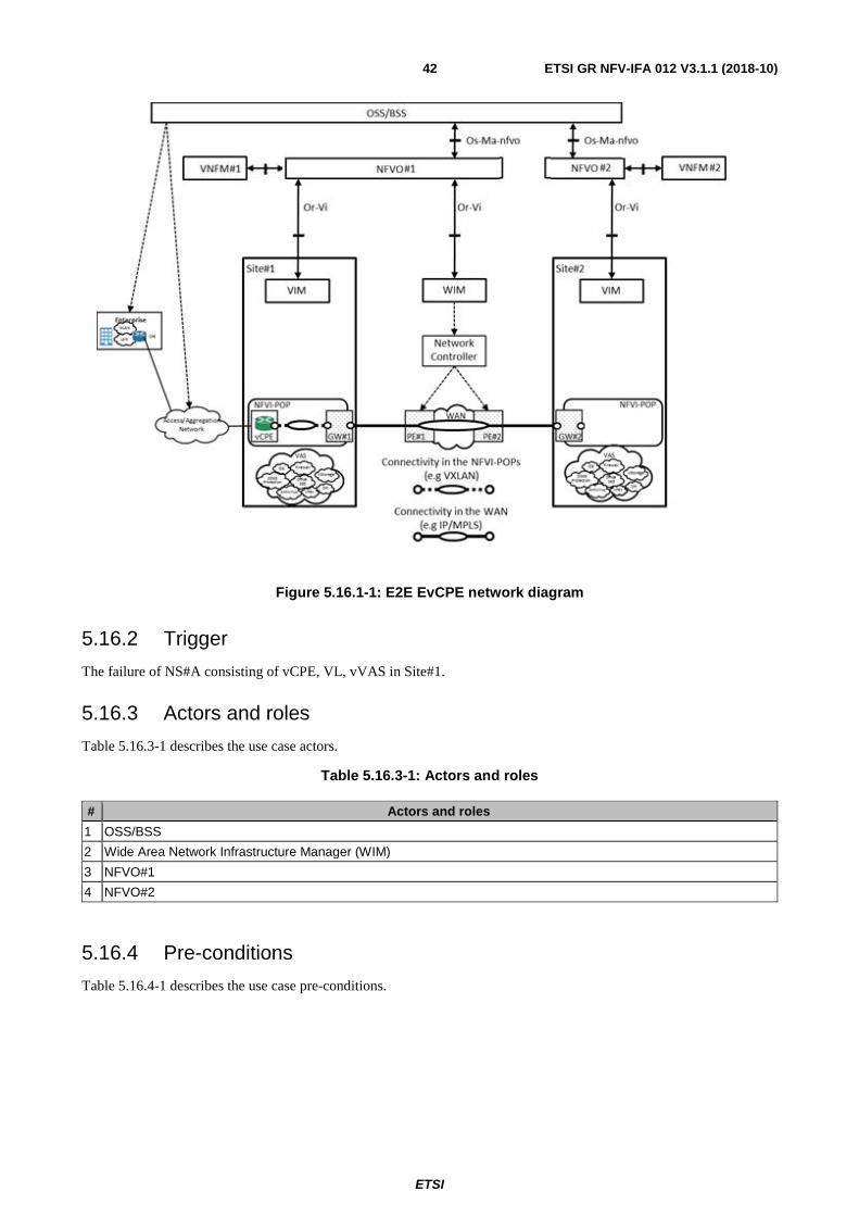
ETSI
ETSI GR NFV-IFA 012 V3.1.1 (2018-10) 42
Figure 5.16.1-1: E2E EvCPE network diagram
5.16.2 Trigger
The failure of NS#A consisting of vCPE, VL, vVAS in Site#1.
5.16.3 Actors and roles
Table 5.16.3-1 describes the use case actors.
Table 5.16.3-1: Actors and roles
# Actors and roles
1 OSS/BSS
2 Wide Area Network Infrastructure Manager (WIM)
3 NFVO#1
4 NFVO#2
5.16.4 Pre-conditions
Table 5.16.4-1 describes the use case pre-conditions.

ETSI
ETSI GR NFV-IFA 012 V3.1.1 (2018-10) 43
Table 5.16.4-1: Pre-conditions
# Pre-conditions Comment
1 An E2E EvCPE service is instantiated and works properly according to the SLA.
E2E EvCPE consisting of services: 1) Access aggregation network (PNFs in legacy network) 2) NS instance #A on Site#1 (created based on NSD#A) that consists of:
• vCPE VNF. • VL (vCPE - vVAS). • vVAS VNF.
2 The infrastructure of the NFVI-PoP at Site#1 and Site#2 and the network infrastructure of the Wide Area Network (WAN) are also physically connected.
5.16.5 Post-conditions
Table 5.16.5-1 describes the use case post-conditions.
Table 5.16.5-1: Post-conditions
# Post-conditions Comment
1 E2E EvCPE service uses VNFs across the two sites.
E2E EvCPE consisting of services: 1) Access aggregation network (PNFs in legacy network) 2) NS instance #B on Site#1 (created based on NSD#B) that consists of:
• vCPE VNF • vLink (vCPE - GW#1) • WAN Link (GW#1- GW#2)
3) NS instance #C on Site#2 (created based on NSD#C) that consists of:
• vVAS VNF • vLink (vVAS - GW#2)
5.16.6 Flow description
Table 5.16.6-1 describes the use case flow.
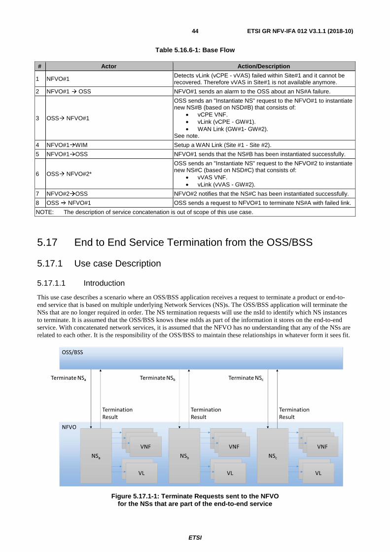
ETSI
ETSI GR NFV-IFA 012 V3.1.1 (2018-10) 44
Table 5.16.6-1: Base Flow
# Actor Action/Description
1 NFVO#1 Detects vLink (vCPE - vVAS) failed within Site#1 and it cannot be recovered. Therefore vVAS in Site#1 is not available anymore.
2 NFVO#1 OSS NFVO#1 sends an alarm to the OSS about an NS#A failure.
3 OSS NFVO#1
OSS sends an "Instantiate NS" request to the NFVO#1 to instantiate new NS#B (based on NSD#B) that consists of:
• vCPE VNF. • vLink (vCPE - GW#1). • WAN Link (GW#1- GW#2).
See note.
4 NFVO#1WIM Setup a WAN Link (Site #1 - Site #2).
5 NFVO#1OSS NFVO#1 sends that the NS#B has been instantiated successfully.
6 OSS NFVO#2*
OSS sends an "Instantiate NS" request to the NFVO#2 to instantiate new NS#C (based on NSD#C) that consists of:
• vVAS VNF. • vLink (vVAS - GW#2).
7 NFVO#2OSS NFVO#2 notifies that the NS#C has been instantiated successfully.
8 OSS NFVO#1 OSS sends a request to NFVO#1 to terminate NS#A with failed link.
NOTE: The description of service concatenation is out of scope of this use case.
5.17 End to End Service Termination from the OSS/BSS
5.17.1 Use case Description
5.17.1.1 Introduction
This use case describes a scenario where an OSS/BSS application receives a request to terminate a product or end-to-end service that is based on multiple underlying Network Services (NS)s. The OSS/BSS application will terminate the NSs that are no longer required in order. The NS termination requests will use the nsId to identify which NS instances to terminate. It is assumed that the OSS/BSS knows these nsIds as part of the information it stores on the end-to-end service. With concatenated network services, it is assumed that the NFVO has no understanding that any of the NSs are related to each other. It is the responsibility of the OSS/BSS to maintain these relationships in whatever form it sees fit.
Figure 5.17.1-1: Terminate Requests sent to the NFVO for the NSs that are part of the end-to-end service

ETSI
ETSI GR NFV-IFA 012 V3.1.1 (2018-10) 45
Once all of the NSs have been terminated, the OSS/BSS will send Delete NS Identifier requests to delete the nsIds that were used for the NS.
Figure 5.17.1-2: Delete nsId requests sent to the NFVO for the NSs that are part of the end-to-end service
Note that if one of the NSs is shared between multiple end-to-end services, then it is assumed that the OSS/BSS is aware of this situation (since the OSS/BSS is the only system with an understanding of end-to-end services). In this case neither a Terminate nor Delete ID request will be sent for that particular NS. Further it is the responsibility of the OSS/BSS to track when all references to an NS are removed and with the termination of the last end-to-end service that uses the NS, the Terminate and Delete ID requests should be sent.
There may be cases where a NS has been re-used without the OSS/BSS knowledge, say when the OSS/BSS instantiates a NS and then this NS is used within another composite NS without the originating OSS/BSS being aware of this. In this case it is expected that when the NFVO receives the terminate NS request, it will not terminate the NS since it is still in use. The result of the termination request will indicate that the termination request was valid but the termination was not carried out. The OSS/BSS should in this case not send the Delete nsId request. If a Delete nsId request is sent, the NFVO will respond with an error result (since the NS is still in an active state).
5.17.1.2 Parallel vs Sequential NS Termination requests
The OSS/BSS can decide to send termination requests for the Network Services in parallel or sequentially. The decision will consider dependencies between the NSs being terminated. It is up to the OSS/BSS to understand these dependencies and make the decision as to whether the requests can be sent in parallel or not, and what order the requests need to be sent if they are sent sequentially. Since the NSs termination requests being received by the NFVO are independent, the expectation is that either sequential or parallel requests can be made by the consumer (the OSS/BSS).
5.17.1.3 Network Service Termination requests to different NFVOs
If the end-to-end service requires the use of Network Services that are on-board in separate NFVOs then the use case essentially stays the same. The OSS/BSS is responsible for identifying the NFVO to which a NS Termination and Delete NS Identification requests are sent and for disconnecting the connectivity between the instantiated NSs, which may involve the deletion of associated physical network connectivity. The OSS/BSS is required to maintain the end-to-end service status and keep track of NS Termination and Delete NS Identification responses from any NFVOs that requests have been made to.

ETSI
ETSI GR NFV-IFA 012 V3.1.1 (2018-10) 46
Figure 5.17.1.2-1: Terminate NS requests sent to each NFVO for the NSs that are part of the end-to-end service
Figure 5.17.1.2-2: Delete nsId requests sent to each NFVO for the NSs that are part of the end-to-end service
5.17.2 Trigger
OSS/BSS determines that it needs to terminate an end-to-end service.
5.17.3 Actors and roles
Table 5.17.3-1 describes the use case actors and roles participating in the use case.
Table 5.17.3-1: Actors and roles
# Actors and roles
1 NVFO
2 OSS/BSS
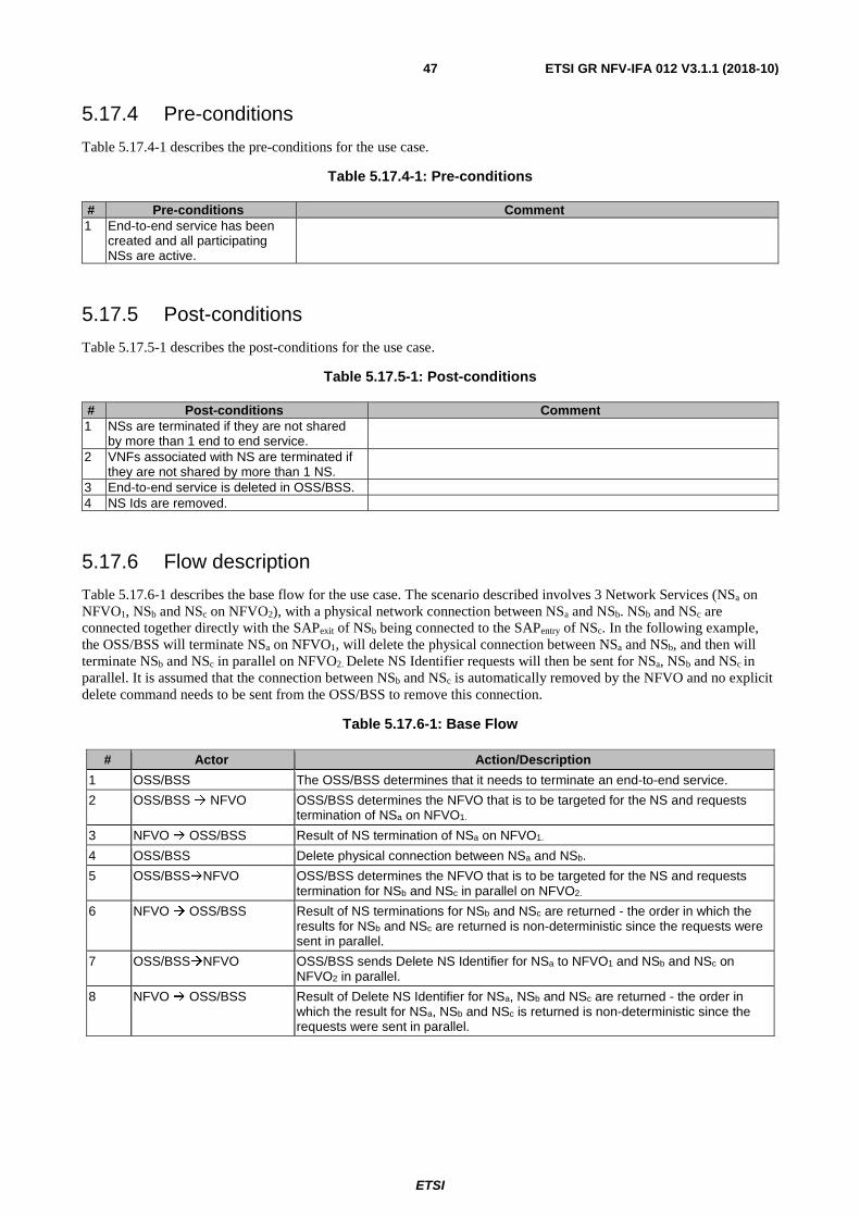
ETSI
ETSI GR NFV-IFA 012 V3.1.1 (2018-10) 47
5.17.4 Pre-conditions
Table 5.17.4-1 describes the pre-conditions for the use case.
Table 5.17.4-1: Pre-conditions
# Pre-conditions Comment 1 End-to-end service has been
created and all participating NSs are active.
5.17.5 Post-conditions
Table 5.17.5-1 describes the post-conditions for the use case.
Table 5.17.5-1: Post-conditions
# Post-conditions Comment 1 NSs are terminated if they are not shared
by more than 1 end to end service.
2 VNFs associated with NS are terminated if they are not shared by more than 1 NS.
3 End-to-end service is deleted in OSS/BSS. 4 NS Ids are removed.
5.17.6 Flow description
Table 5.17.6-1 describes the base flow for the use case. The scenario described involves 3 Network Services (NSa on NFVO1, NSb and NSc on NFVO2), with a physical network connection between NSa and NSb. NSb and NSc are connected together directly with the SAPexit of NSb being connected to the SAPentry of NSc. In the following example, the OSS/BSS will terminate NSa on NFVO1, will delete the physical connection between NSa and NSb, and then will terminate NSb and NSc in parallel on NFVO2. Delete NS Identifier requests will then be sent for NSa, NSb and NSc in parallel. It is assumed that the connection between NSb and NSc is automatically removed by the NFVO and no explicit delete command needs to be sent from the OSS/BSS to remove this connection.
Table 5.17.6-1: Base Flow
# Actor Action/Description
1 OSS/BSS The OSS/BSS determines that it needs to terminate an end-to-end service.
2 OSS/BSS NFVO OSS/BSS determines the NFVO that is to be targeted for the NS and requests termination of NSa on NFVO1.
3 NFVO OSS/BSS Result of NS termination of NSa on NFVO1.
4 OSS/BSS Delete physical connection between NSa and NSb.
5 OSS/BSSNFVO OSS/BSS determines the NFVO that is to be targeted for the NS and requests termination for NSb and NSc in parallel on NFVO2.
6 NFVO OSS/BSS Result of NS terminations for NSb and NSc are returned - the order in which the results for NSb and NSc are returned is non-deterministic since the requests were sent in parallel.
7 OSS/BSSNFVO OSS/BSS sends Delete NS Identifier for NSa to NFVO1 and NSb and NSc on NFVO2 in parallel.
8 NFVO OSS/BSS Result of Delete NS Identifier for NSa, NSb and NSc are returned - the order in which the result for NSa, NSb and NSc is returned is non-deterministic since the requests were sent in parallel.

ETSI
ETSI GR NFV-IFA 012 V3.1.1 (2018-10) 48
5.18 Switching from several active Nsa instances to new NSb instances
5.18.1 Use case Description
This use case covers a scenario where there are two versions of an NSDa - versions 1 and 2 - with partly different characteristics in the context of additional other versions of NSDa. The OSS/BSS will send a "create NS" request for a new NSb based on a specific NSDb version and after that to generate NSb instances. These NSb instances should be used instead of the active instances of the Nsa based on the NSDa versions 1 and 2. That means after the generation of the NSb instances these Nsa instances should be terminated and deleted. In the next step the corresponding NSDa versions should be deleted because the OSS/BSS is aware that these NSDa versions are no longer required.
5.18.2 Trigger
The OSS/BSS requests to create a new NSb.
5.18.3 Actors and roles
Table 5.18.3-1 describes the use case actors who are involved in the use case.
Table 5.18.3-1: Actors and roles
# Actors and roles
1 NVFO
2 OSS/BSS
5.18.4 Pre-conditions
Table 5.18.4-1 describes the pre-conditions for the use case.
Table 5.18.4-1: Pre-conditions
# Pre-conditions Comment 1 Nsa instances based on NSDa
versions 1 and 2 are available in the network.
2 The OSS/BSS is aware of the Nsa instances and the corresponding NSDs that should be deleted and can identify these NSDs.
5.18.5 Post-conditions
Table 5.18.5-1 describes the post-conditions for the use case.

ETSI
ETSI GR NFV-IFA 012 V3.1.1 (2018-10) 49
Table 5.18.5-1: Post-conditions
# Post-conditions Comment 1 The NSDb is onboarded.
2 New NSb instances are available and active in the network.
3 The Nsa instances based on the NSDa versions 1 and 2 are terminated and deleted.
4 The NSDa versions 1 and 2 are deleted.
5.18.6 Flow description
Table 5.18.6-1 describes the base flow for the use case.
Table 5.18.6-1: Base Flow
# Actor Action/Description 1 OSS/BSS The OSS/BSS identifies that a new NSb based on an NSDb should be created. 2 OSS/BSS -> NFVO The OSS/BSS sends a request to the NFVO to on-board the NSDb for this NSb. 3 NFVO -> OSS/BSS The NFVO returns a successful response with the corresponding NSD ID including
the version numbering, if the requested operation was successful. Otherwise the OSS/BSS receives a failure response with the error cause from the NFVO.
4 OSS/BSS -> NFVO After the successful operation the OSS/BSS requests to create the new NSb in connection with this new on-boarded NSDb.
5 NFVO -> OSS/BSS If the requested operation was successful the NFVO returns a successful response with the corresponding NS ID instance for which the associated NSInfo information element has been created. Otherwise the OSS/BSS receives a failure response with the error cause from the NFVO.
6 OSS/BSS -> NFVO After the successful operation the OSS/BSS requests the instantiation of the NSb in connection with this new created NSInfo information element.
7 NFVO -> OSS/BSS If the requested operation was successful the NS has been instantiated and the NFVO returns a successful response with the corresponding identifier of the NS lifecycleOperationOccurrenceId. Otherwise the OSS/BSS receives a failure response with the appropriate error information that are provided in the "result" Lifecycle Change Notification from the NFVO.
8 OSS/BSS The OSS/BSS will execute the necessary steps to switch to using the new NSb instance instead of the formerly used Nsa instance. See note 1.
9 OSS/BSS -> NFVO The OSS/BSS requests to terminate the instance of the Nsa. 10 NFVO -> OSS/BSS The NFVO will return whether the operation was successful or unsuccessful.
See note 2. 11 OSS/BSS -> NFVO If the operation was successful the OSS/BSS makes a one step request to the
NFVO to delete the Nsa instances based on the NSDa versions 1 and 2 as well as the related NSDs.
12 NFVO -> OSS/BSS If the requested operation was successful the NFVO returns a successful response. If the deletion is pending because at least one of the NSDs is still in use then the deletion will only be realized once all related and instantiated NSs are terminated. This will be expressed in the output parameter(s). Otherwise the OSS/BSS gets a failure response with the error cause from the NFVO.
NOTE 1: The details of this step will not be described in this use case. NOTE 2: The steps 4, 5, 6, 7, 8, 9 and 10 should be repeated for each instance of Nsa based on the NSDa versions 1
and 2.
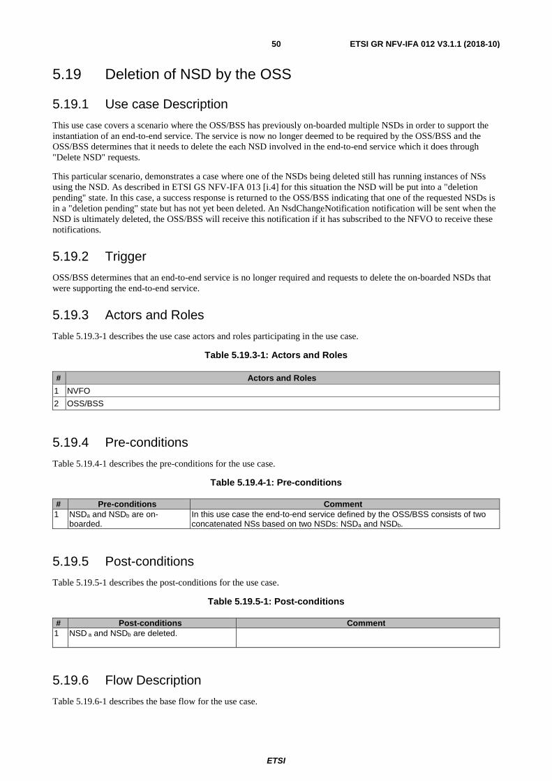
ETSI
ETSI GR NFV-IFA 012 V3.1.1 (2018-10) 50
5.19 Deletion of NSD by the OSS
5.19.1 Use case Description
This use case covers a scenario where the OSS/BSS has previously on-boarded multiple NSDs in order to support the instantiation of an end-to-end service. The service is now no longer deemed to be required by the OSS/BSS and the OSS/BSS determines that it needs to delete the each NSD involved in the end-to-end service which it does through "Delete NSD" requests.
This particular scenario, demonstrates a case where one of the NSDs being deleted still has running instances of NSs using the NSD. As described in ETSI GS NFV-IFA 013 [i.4] for this situation the NSD will be put into a "deletion pending" state. In this case, a success response is returned to the OSS/BSS indicating that one of the requested NSDs is in a "deletion pending" state but has not yet been deleted. An NsdChangeNotification notification will be sent when the NSD is ultimately deleted, the OSS/BSS will receive this notification if it has subscribed to the NFVO to receive these notifications.
5.19.2 Trigger
OSS/BSS determines that an end-to-end service is no longer required and requests to delete the on-boarded NSDs that were supporting the end-to-end service.
5.19.3 Actors and Roles
Table 5.19.3-1 describes the use case actors and roles participating in the use case.
Table 5.19.3-1: Actors and Roles
# Actors and Roles
1 NVFO
2 OSS/BSS
5.19.4 Pre-conditions
Table 5.19.4-1 describes the pre-conditions for the use case.
Table 5.19.4-1: Pre-conditions
# Pre-conditions Comment 1 NSDa and NSDb are on-
boarded. In this use case the end-to-end service defined by the OSS/BSS consists of two concatenated NSs based on two NSDs: NSDa and NSDb.
5.19.5 Post-conditions
Table 5.19.5-1 describes the post-conditions for the use case.
Table 5.19.5-1: Post-conditions
# Post-conditions Comment 1 NSD a and NSDb are deleted.
5.19.6 Flow Description
Table 5.19.6-1 describes the base flow for the use case.
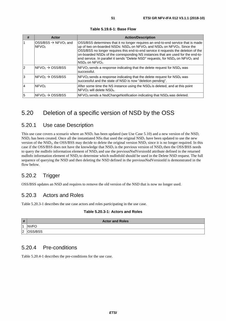
ETSI
ETSI GR NFV-IFA 012 V3.1.1 (2018-10) 51
Table 5.19.6-1: Base Flow
# Actor Action/Description
1 OSS/BSS NFVO1 and NFVO2
OSS/BSS determines that it no longer requires an end-to-end service that is made up of two on-boarded NSDs: NSDa on NFVO1 and NSDb on NFVO2. Since the OSS/BSS no longer requires this end-to-end service it requests the deletion of the on-boarded NSDs of the corresponding NS instances that are used for the end-to-end service. In parallel it sends "Delete NSD" requests, for NSDa on NFVO1 and NSDb on NFVO2.
2 NFVO1 OSS/BSS NFVO1 sends a response indicating that the delete request for NSDa was successful.
3 NFVO2 OSS/BSS NFVO2 sends a response indicating that the delete request for NSDb was successful and the state of NSD is now "deletion pending".
4 NFVO2 After some time the NS instance using the NSDb is deleted, and at this point NFVO2 will delete NSDb.
5 NFVO2 OSS/BSS NFVO2 sends a NsdChangeNotification indicating that NSDb was deleted.
5.20 Deletion of a specific version of NSD by the OSS
5.20.1 Use case Description
This use case covers a scenario where an NSD1 has been updated (see Use Case 5.10) and a new version of the NSD, NSD2 has been created. Once all the instantiated NSs that used the original NSD1 have been updated to use the new version of the NSD2, the OSS/BSS may decide to delete the original version NSD1 since it is no longer required. In this case if the OSS/BSS does not have the knowledge that NSD1 is the previous version of NSD2 then the OSS/BSS needs to query the nsdInfo information element of NSD2 and use the previousNsdVersionId attribute defined in the returned nsdInfo information element of NSD2 to determine which nsdInfoId should be used in the Delete NSD request. The full sequence of querying the NSD and then deleting the NSD defined in the previousNsdVersionId is demonstrated in the flow below.
5.20.2 Trigger
OSS/BSS updates an NSD and requires to remove the old version of the NSD that is now no longer used.
5.20.3 Actors and Roles
Table 5.20.3-1 describes the use case actors and roles participating in the use case.
Table 5.20.3-1: Actors and Roles
# Actor and Roles
1 NVFO
2 OSS/BSS
5.20.4 Pre-conditions
Table 5.20.4-1 describes the pre-conditions for the use case.
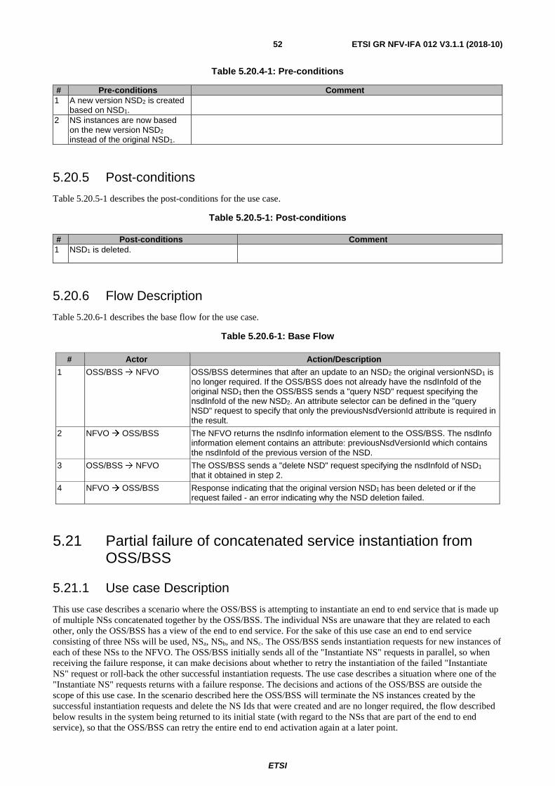
ETSI
ETSI GR NFV-IFA 012 V3.1.1 (2018-10) 52
Table 5.20.4-1: Pre-conditions
# Pre-conditions Comment 1 A new version NSD2 is created
based on NSD1.
2 NS instances are now based on the new version NSD2 instead of the original NSD1.
5.20.5 Post-conditions
Table 5.20.5-1 describes the post-conditions for the use case.
Table 5.20.5-1: Post-conditions
# Post-conditions Comment 1 NSD1 is deleted.
5.20.6 Flow Description
Table 5.20.6-1 describes the base flow for the use case.
Table 5.20.6-1: Base Flow
# Actor Action/Description
1 OSS/BSS NFVO OSS/BSS determines that after an update to an NSD2 the original versionNSD1 is no longer required. If the OSS/BSS does not already have the nsdInfoId of the original NSD1 then the OSS/BSS sends a "query NSD" request specifying the nsdInfoId of the new NSD2. An attribute selector can be defined in the "query NSD" request to specify that only the previousNsdVersionId attribute is required in the result.
2 NFVO OSS/BSS The NFVO returns the nsdInfo information element to the OSS/BSS. The nsdInfo information element contains an attribute: previousNsdVersionId which contains the nsdInfoId of the previous version of the NSD.
3 OSS/BSS NFVO The OSS/BSS sends a "delete NSD" request specifying the nsdInfoId of NSD1 that it obtained in step 2.
4 NFVO OSS/BSS Response indicating that the original version NSD1 has been deleted or if the request failed - an error indicating why the NSD deletion failed.
5.21 Partial failure of concatenated service instantiation from OSS/BSS
5.21.1 Use case Description
This use case describes a scenario where the OSS/BSS is attempting to instantiate an end to end service that is made up of multiple NSs concatenated together by the OSS/BSS. The individual NSs are unaware that they are related to each other, only the OSS/BSS has a view of the end to end service. For the sake of this use case an end to end service consisting of three NSs will be used, NSa, NSb, and NSc. The OSS/BSS sends instantiation requests for new instances of each of these NSs to the NFVO. The OSS/BSS initially sends all of the "Instantiate NS" requests in parallel, so when receiving the failure response, it can make decisions about whether to retry the instantiation of the failed "Instantiate NS" request or roll-back the other successful instantiation requests. The use case describes a situation where one of the "Instantiate NS" requests returns with a failure response. The decisions and actions of the OSS/BSS are outside the scope of this use case. In the scenario described here the OSS/BSS will terminate the NS instances created by the successful instantiation requests and delete the NS Ids that were created and are no longer required, the flow described below results in the system being returned to its initial state (with regard to the NSs that are part of the end to end service), so that the OSS/BSS can retry the entire end to end activation again at a later point.
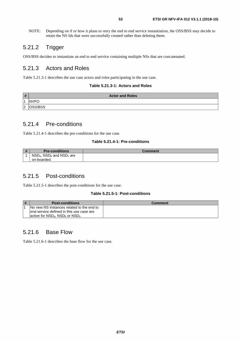
ETSI
ETSI GR NFV-IFA 012 V3.1.1 (2018-10) 53
NOTE: Depending on if or how it plans to retry the end to end service instantiation, the OSS/BSS may decide to retain the NS Ids that were successfully created rather than deleting them.
5.21.2 Trigger
OSS/BSS decides to instantiate an end to end service containing multiple NSs that are concatenated.
5.21.3 Actors and Roles
Table 5.21.3-1 describes the use case actors and roles participating in the use case.
Table 5.21.3-1: Actors and Roles
# Actor and Roles
1 NVFO
2 OSS/BSS
5.21.4 Pre-conditions
Table 5.21.4-1 describes the pre-conditions for the use case.
Table 5.21.4-1: Pre-conditions
# Pre-conditions Comment 1 NSDa, NSDb and NSDc are
on-boarded.
5.21.5 Post-conditions
Table 5.21.5-1 describes the post-conditions for the use case.
Table 5.21.5-1: Post-conditions
# Post-conditions Comment 1 No new NS instances related to the end to
end service defined in this use case are active for NSDa, NSDb or NSDc.
5.21.6 Base Flow
Table 5.21.6-1 describes the base flow for the use case.
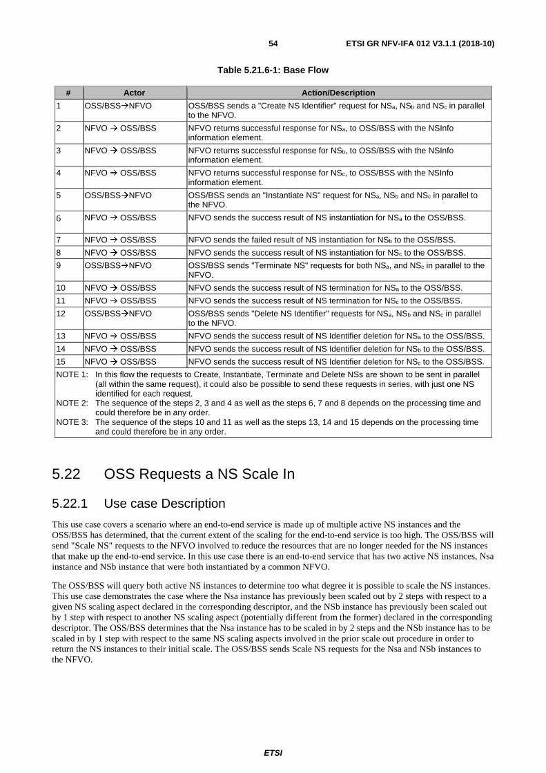
ETSI
ETSI GR NFV-IFA 012 V3.1.1 (2018-10) 54
Table 5.21.6-1: Base Flow
# Actor Action/Description
1 OSS/BSSNFVO
OSS/BSS sends a "Create NS Identifier" request for NSa, NSb and NSc in parallel to the NFVO.
2 NFVO OSS/BSS
NFVO returns successful response for NSa, to OSS/BSS with the NSInfo information element.
3 NFVO OSS/BSS
NFVO returns successful response for NSb, to OSS/BSS with the NSInfo information element.
4 NFVO OSS/BSS NFVO returns successful response for NSc, to OSS/BSS with the NSInfo information element.
5 OSS/BSSNFVO
OSS/BSS sends an "Instantiate NS" request for NSa, NSb and NSc in parallel to the NFVO.
6 NFVO OSS/BSS NFVO sends the success result of NS instantiation for NSa to the OSS/BSS.
7 NFVO OSS/BSS NFVO sends the failed result of NS instantiation for NSb to the OSS/BSS.
8 NFVO OSS/BSS NFVO sends the success result of NS instantiation for NSc to the OSS/BSS.
9 OSS/BSSNFVO
OSS/BSS sends "Terminate NS" requests for both NSa, and NSc in parallel to the NFVO.
10 NFVO OSS/BSS NFVO sends the success result of NS termination for NSa to the OSS/BSS.
11 NFVO OSS/BSS NFVO sends the success result of NS termination for NSc to the OSS/BSS.
12 OSS/BSSNFVO
OSS/BSS sends "Delete NS Identifier" requests for NSa, NSb and NSc in parallel to the NFVO.
13 NFVO OSS/BSS NFVO sends the success result of NS Identifier deletion for NSa to the OSS/BSS.
14 NFVO OSS/BSS NFVO sends the success result of NS Identifier deletion for NSb to the OSS/BSS.
15 NFVO OSS/BSS NFVO sends the success result of NS Identifier deletion for NSc to the OSS/BSS.
NOTE 1: In this flow the requests to Create, Instantiate, Terminate and Delete NSs are shown to be sent in parallel (all within the same request), it could also be possible to send these requests in series, with just one NS identified for each request.
NOTE 2: The sequence of the steps 2, 3 and 4 as well as the steps 6, 7 and 8 depends on the processing time and could therefore be in any order.
NOTE 3: The sequence of the steps 10 and 11 as well as the steps 13, 14 and 15 depends on the processing time and could therefore be in any order.
5.22 OSS Requests a NS Scale In
5.22.1 Use case Description
This use case covers a scenario where an end-to-end service is made up of multiple active NS instances and the OSS/BSS has determined, that the current extent of the scaling for the end-to-end service is too high. The OSS/BSS will send "Scale NS" requests to the NFVO involved to reduce the resources that are no longer needed for the NS instances that make up the end-to-end service. In this use case there is an end-to-end service that has two active NS instances, Nsa instance and NSb instance that were both instantiated by a common NFVO.
The OSS/BSS will query both active NS instances to determine too what degree it is possible to scale the NS instances. This use case demonstrates the case where the Nsa instance has previously been scaled out by 2 steps with respect to a given NS scaling aspect declared in the corresponding descriptor, and the NSb instance has previously been scaled out by 1 step with respect to another NS scaling aspect (potentially different from the former) declared in the corresponding descriptor. The OSS/BSS determines that the Nsa instance has to be scaled in by 2 steps and the NSb instance has to be scaled in by 1 step with respect to the same NS scaling aspects involved in the prior scale out procedure in order to return the NS instances to their initial scale. The OSS/BSS sends Scale NS requests for the Nsa and NSb instances to the NFVO.
ETSI
ETSI GR NFV-IFA 012 V3.1.1 (2018-10) 55
The order in which the Scale NS requests are sent by the OSS/BSS to the NFVO may be important, the end-to-end service may contain a number of NSs that are essentially chained together. Scaling one NS in the chain may overload other NSs in the chain if they are not scaled in an appropriate order. It is up to the OSS/BSS to use its knowledge of the end-to-end service to determine the appropriate order. In this use case, the request to scale in the Nsa instance will be processed and completed prior to the request to scale in the NSb instance.
Since the Scale NS request is making use of steps, the scaleType attribute will be set to SCALE_NS which mandates the usage of the ScaleNsData information element and the ScaleNsBySteps information element will then be used with the scalingDirection attribute set to SCALE_IN, and define the number of steps used for scaling.
5.22.2 Trigger
The OSS/BSS determines that the NSs underlying an end-to-end service are being under-utilized.
5.22.3 Actors and Roles
Table 5.22.3-1 describes the use case actors and roles participating in the use case.
Table 5.22.3-1: Actors and Roles
# Actor and Roles
1 NFVO
2 OSS/BSS
5.22.4 Pre-conditions
Table 5.22.4-1 describes the pre-conditions for the use case.
Table 5.22.4-1: Pre-conditions
# Pre-conditions Comment 1 A concatenated end-to-end
service made up of an Nsa instance and an NSb instance is active.
2 The OSS/BSS has taken appropriate steps to prepare Nsa, NSb and any higher level applications that depend on Nsa and NSb for the scaling operation.
This may include changing the higher level application into an inactive state.
5.22.5 Post-conditions
Table 5.22.5-1 describes the post-conditions for the use case.
Table 5.22.5-1: Post-conditions
# Post-conditions Comment 1 The Nsa instance and NSb instance are
both successfully scaled in.
5.22.6 Flow Description
Table 5.22.6-1 describes the base flow for the use case.

ETSI
ETSI GR NFV-IFA 012 V3.1.1 (2018-10) 56
Table 5.22.6-1: Base Flow
# Actor Action/Description
1 OSS/BSS OSS/BSS determines that an end-to-end service is under-utilized.
2 OSS/BSS NFVO The OSS/BSS sends a NS Query request containing the NSIds of the Nsa instance and the NSb instance.
3
NFVO OSS/BSS The NFVO returns NsInfo information elements for both Nsa and NSb instances that each contain NsScaleInfo information elements. The NsScaleInfo information elements contain details of the level to which the NS instances have been scaled. The OSS/BSS will use this information to determine the appropriate Scale NS request steps for each NS. In this use case the OSS/BSS determines that Nsa instance needs to be scaled in by 2 steps with respect to a given NS scaling declared in the corresponding descriptor and NSb instance needs to be scaled in by 1 step with respect to another NS scaling aspect (potentially different from the former) declared in the corresponding descriptor. Further, the OSS/BSS uses its knowledge of the end-to-end service to determine that the Scale NS request for the Nsa instance should occur prior to the Scale NS request for the NSb instance.
4 OSS/BSS NFVO The OSS/BSS sends an Scale NS request , with the scalingDirection attribute set to SCALE_IN, to the NFVO for the Nsa instance.
5 NFVO OSS/BSS The NFVO sends a response to the OSS/BSS indicating that the Scale NS request was successful or failed. If failed - the OSS/BSS may inspect the error reason and attempt to retry the request, or it may decide to abort the entire end-to-end service scale in change and terminate the workflow here. If successful, the flow will continue with step 6.
6 OSS/BSS NFVO The OSS/BSS sends an Scale NS request, with the scalingDirection attribute set to SCALE_IN, to the NFVO for the NSb instance.
7 NFVO OSS/BSS The NFVO sends a response to the OSS/BSS indicating that the Scale NS request was successful or failed. If the Scale NS request for NSb fails - the OSS/BSS may determine that it needs to undo the previously sent Scale NS request for Nsa, in which case it will send a Scale NS request, with the scalingDirection attribute set to SCALE_OUT, to return it to the original higher scale.
5.23 OSS Copies VNF Package from one NFVO to another NFVO
5.23.1 Use case Description
This use case covers a scenario where the OSS/BSS copies an On-boarded VNF Package from one NFVO to another NFVO by fetching the VNF Package from the first NFVO and then On-boarding the VNF Package on the second NFVO.
It is assumed that the OSS/BSS performing this action does not have the on-boarded VNF Package, i.e. the OSS/BSS was not the OSS/BSS that performed the first on-boarding.
5.23.2 Trigger
The OSS/BSS determines that it needs to copy an On-boarded VNF Package from an existing NFVO onto a second NFVO.
5.23.3 Actors and Roles
Table 5.23.3-1 describes the use case actors and roles participating in the use case.
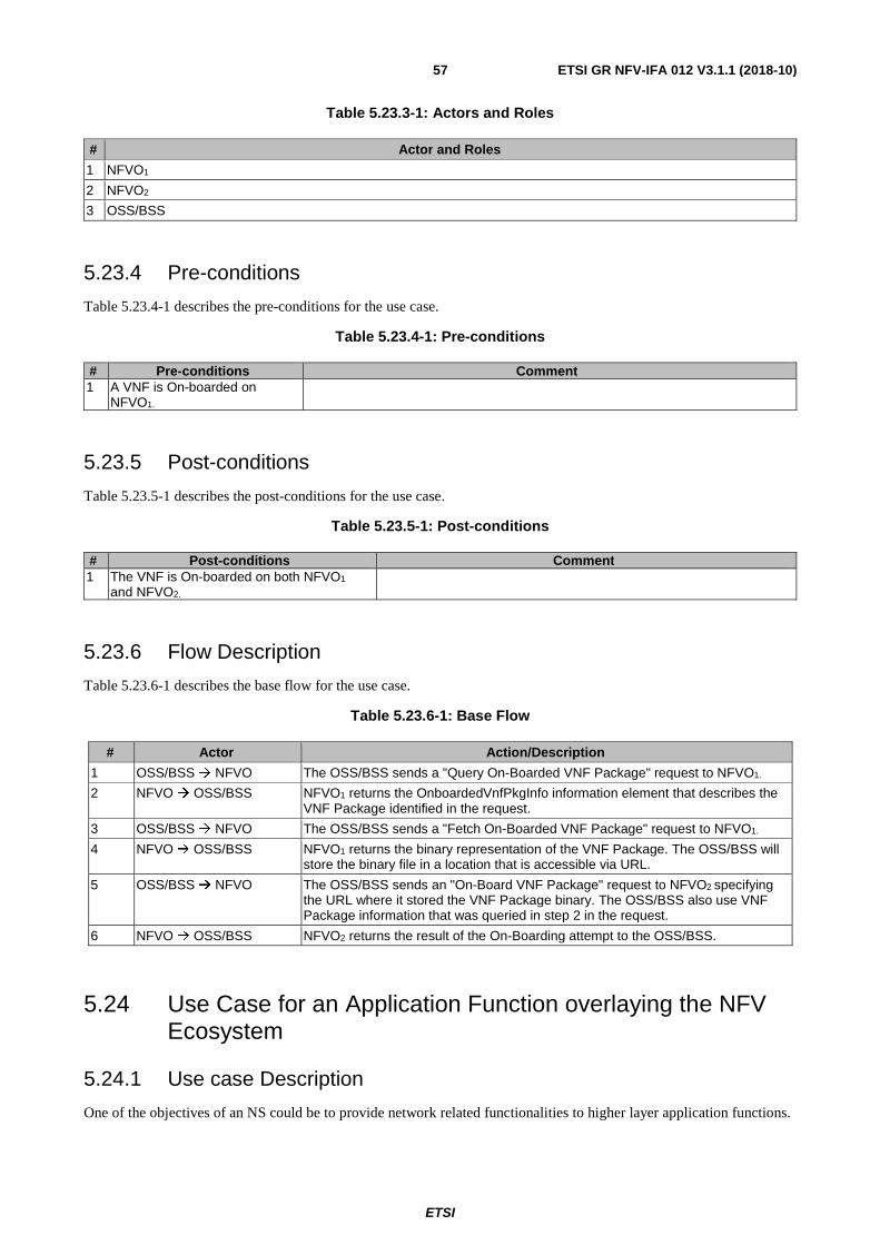
ETSI
ETSI GR NFV-IFA 012 V3.1.1 (2018-10) 57
Table 5.23.3-1: Actors and Roles
# Actor and Roles
1 NFVO1
2 NFVO2
3 OSS/BSS
5.23.4 Pre-conditions
Table 5.23.4-1 describes the pre-conditions for the use case.
Table 5.23.4-1: Pre-conditions
# Pre-conditions Comment 1 A VNF is On-boarded on
NFVO1.
5.23.5 Post-conditions
Table 5.23.5-1 describes the post-conditions for the use case.
Table 5.23.5-1: Post-conditions
# Post-conditions Comment 1 The VNF is On-boarded on both NFVO1
and NFVO2.
5.23.6 Flow Description
Table 5.23.6-1 describes the base flow for the use case.
Table 5.23.6-1: Base Flow
# Actor Action/Description
1 OSS/BSS NFVO The OSS/BSS sends a "Query On-Boarded VNF Package" request to NFVO1.
2 NFVO OSS/BSS NFVO1 returns the OnboardedVnfPkgInfo information element that describes the VNF Package identified in the request.
3 OSS/BSS NFVO The OSS/BSS sends a "Fetch On-Boarded VNF Package" request to NFVO1.
4 NFVO OSS/BSS NFVO1 returns the binary representation of the VNF Package. The OSS/BSS will store the binary file in a location that is accessible via URL.
5 OSS/BSS NFVO The OSS/BSS sends an "On-Board VNF Package" request to NFVO2 specifying the URL where it stored the VNF Package binary. The OSS/BSS also use VNF Package information that was queried in step 2 in the request.
6 NFVO OSS/BSS NFVO2 returns the result of the On-Boarding attempt to the OSS/BSS.
5.24 Use Case for an Application Function overlaying the NFV Ecosystem
5.24.1 Use case Description
One of the objectives of an NS could be to provide network related functionalities to higher layer application functions.

ETSI
ETSI GR NFV-IFA 012 V3.1.1 (2018-10) 58
These higher layer Application Functions (Afs), that may be virtualised and/or non-virtualised, could rely on the functional/operational characteristics of the NS or one or more of its constituent VNFs that are parts of NS(s) to carry out their respective functions. For example multimedia application that rely on the underlying network functions/NSs for providing connectivity requirements amongst other things.
Vice versa the VNFs and/or the NS(s) may also utilize the functions provided by the Afs for their own operational/functional support, for example traffic analytic functions that may analyse KPIs of VNF(s). In this respect, the Afs and the underlying VNF(s)/NS(s) could exchange service related primitives.
Moreover, the AF(s) can also support customer facing services via API(s) to the user(s), and can serve as an entry point towards the underlying NS.
The Afs are not part of the VNFFG and are loosely coupled to the NS. This means that the presence or absence of an AF will have no impact on the functional role of the underlying NS, but it may utilize specific parameters and/or information from the NS in order to provide (value added) functionalities/services to higher entities. Or it may provide functionalities/services that may be used by the VNF(s) of a NS to enrich the functionalities/services provided by them.
In other words, the Afs form an overlay over the VNFs or the NS. This concept and the relationship between the NS and the Afs is illustrated in figure 5.24.1-1.
Figure 5.24.1-1: A Service instance consists of Afs as an overlay on VNFs
The interaction between the AF(s) and the underlying NS(s) and/or one or more of its constituent VNFs may have implications on the requirements of existing interface(s) defined for the Os-Ma-Nfvo reference point and may require the definition of new requirement(s) and interface(s).
If changes are triggered within the MANO ecosystem for example a scale up action from the NFVO that has a relation to the AF then the OSS/BSS and the AF should be aware of this. It could be required that such actions need an acknowledgement from the OSS/BSS / AF before the execution of them.
For the use case scenario that is depicted in figure 5.24.1-2, consider an example of an AF that deals with providing network analytics to its customers. In this context the customer can be an MVNO and/or an end-user. Such an AF can also exist as a standalone entity that is realized within the NFV environment sharing the same MANO and OSS/BSS. The underlying NS is composed of the following VNFs inter-connected in the order of their listing:
1) FW/AAA - for providing access control to the incoming service requests from the users.
2) vEPC for providing mobile communication services to the end-users.

ETSI
ETSI GR NFV-IFA 012 V3.1.1 (2018-10) 59
NS
vEPC vFW/AAA
RAN
NFVI
OSS/BSS NFVO
VNFM
VIM
MANO
AF
(Network Analytics Functions)
Network
Stats
Virtual Links Undefined Links
User: MVNO
User: Subscriber
Figure 5.24.1-2: Use Case Scenario
In this use case the AF will interact with all the VNFs forming the NS and collecting performance information from which relevant network performance statistics are derived and provided to the customers subscribed to the AF.
The subscription method will be different depending on the AF's customer type, e.g. MVNO or end-user.
The customers can then utilize these statistics for their own purpose. The AF can also provide detailed statistics to the NFVO via the OSS/BSS that could be used by the NFVO e.g. to carry out LCM actions on NS(s). For simplicity, assume the AF user is an MVNO.
5.24.2 Trigger
A request by a customer for the provisioning of network statistics.
5.24.3 Actors and Roles
Table 5.24.3-1 describes the use case actors.
Table 5.24.3-1: Actors and roles
# Actor and Roles
1 NS: Network Service composed of FW/AAA and vEPC VNFs interconnected with each other
2 AF: Application Function providing Network Analytic Functions
3 OSS/BSS
4 NFVO
5 Users: End-user, MVNO, NFV MANO. Consider only an MVNO as a user for this use case
5.24.4 Pre-conditions
Table 5.24.4-1 describes the use case pre-conditions.

ETSI
ETSI GR NFV-IFA 012 V3.1.1 (2018-10) 60
Table 5.24.4-1: Pre-conditions
# Pre-conditions Comment 1 The NS with the two VNFs (FW/AAA
and vEPC) is active. The assumption in this use case is that the vEPC is a VNF. There are also other realization variants possible.
2 The customer (MVNO in our case) requests the OSS/BSS for network statistics about a particular NS including the network statistics of interest.
5.24.5 Post-conditions
Table 5.24.5-1 describes the use case post-conditions.
Table 5.24.5-1: Post-conditions
# Post-conditions Comment 1 The user (that is an MVNO) is receiving
the outcome of relevant services of the AF (e.g. network statistics).
5.24.6 Flow Description
Table 5.24.6-1 describes the use case flow.
Table 5.24.6-1: Base Flow
# Actor Action/Description 1 OSS/BSS NFVO The OSS/BSS requests the NFVO for network statistics about a
particular NS. In this request the OSS/BSS will indicate the network statistics of interest.
2 NFVO The NFVO will provide the statistical requirements to the corresponding AF and the NS.
3 NFVO OSS/BSS The NFVO responds with an acknowledgement to the OSS/BSS as soon as the particular AF and the NS are ready to communicate together. See note 1.
4 OSS/BSS NFVO
The OSS/BSS forwards the network statistics to the NFVO to enable it for its LCM of the NS if the NFVO had requested this service. See note 2.
NOTE 1: Afterwards the NS starts sending the necessary information to the AF. The AF starts sending the requested network statistics derived from the information received by the NS to the OSS/BSS.
NOTE 2: The OSS/BSS can use the network statistics as well in order to provide additional information to the user(s) - e.g. trend statements about traffic, etc. - and/or to make their own decisions regarding subsequent network and service management activities.
6 Reference point and interface recommendations
6.1 Introduction This clause describes and refers to recommendations which apply to the Os-Ma-nfvo reference point and the corresponding interfaces.
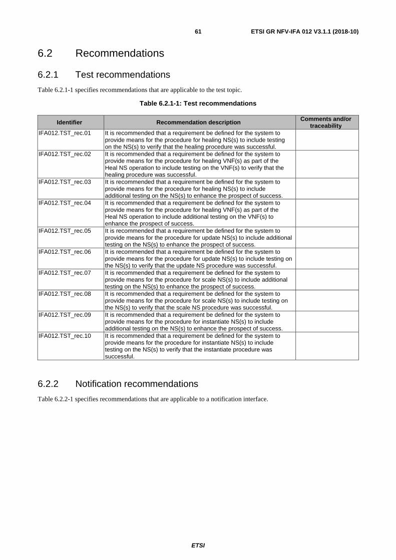
ETSI
ETSI GR NFV-IFA 012 V3.1.1 (2018-10) 61
6.2 Recommendations
6.2.1 Test recommendations
Table 6.2.1-1 specifies recommendations that are applicable to the test topic.
Table 6.2.1-1: Test recommendations
Identifier Recommendation description Comments and/or traceability
IFA012.TST_rec.01
It is recommended that a requirement be defined for the system to provide means for the procedure for healing NS(s) to include testing on the NS(s) to verify that the healing procedure was successful.
IFA012.TST_rec.02 It is recommended that a requirement be defined for the system to provide means for the procedure for healing VNF(s) as part of the Heal NS operation to include testing on the VNF(s) to verify that the healing procedure was successful.
IFA012.TST_rec.03 It is recommended that a requirement be defined for the system to provide means for the procedure for healing NS(s) to include additional testing on the NS(s) to enhance the prospect of success.
IFA012.TST_rec.04 It is recommended that a requirement be defined for the system to provide means for the procedure for healing VNF(s) as part of the Heal NS operation to include additional testing on the VNF(s) to enhance the prospect of success.
IFA012.TST_rec.05 It is recommended that a requirement be defined for the system to provide means for the procedure for update NS(s) to include additional testing on the NS(s) to enhance the prospect of success.
IFA012.TST_rec.06 It is recommended that a requirement be defined for the system to provide means for the procedure for update NS(s) to include testing on the NS(s) to verify that the update NS procedure was successful.
IFA012.TST_rec.07 It is recommended that a requirement be defined for the system to provide means for the procedure for scale NS(s) to include additional testing on the NS(s) to enhance the prospect of success.
IFA012.TST_rec.08 It is recommended that a requirement be defined for the system to provide means for the procedure for scale NS(s) to include testing on the NS(s) to verify that the scale NS procedure was successful.
IFA012.TST_rec.09 It is recommended that a requirement be defined for the system to provide means for the procedure for instantiate NS(s) to include additional testing on the NS(s) to enhance the prospect of success.
IFA012.TST_rec.10 It is recommended that a requirement be defined for the system to provide means for the procedure for instantiate NS(s) to include testing on the NS(s) to verify that the instantiate procedure was successful.
6.2.2 Notification recommendations
Table 6.2.2-1 specifies recommendations that are applicable to a notification interface.
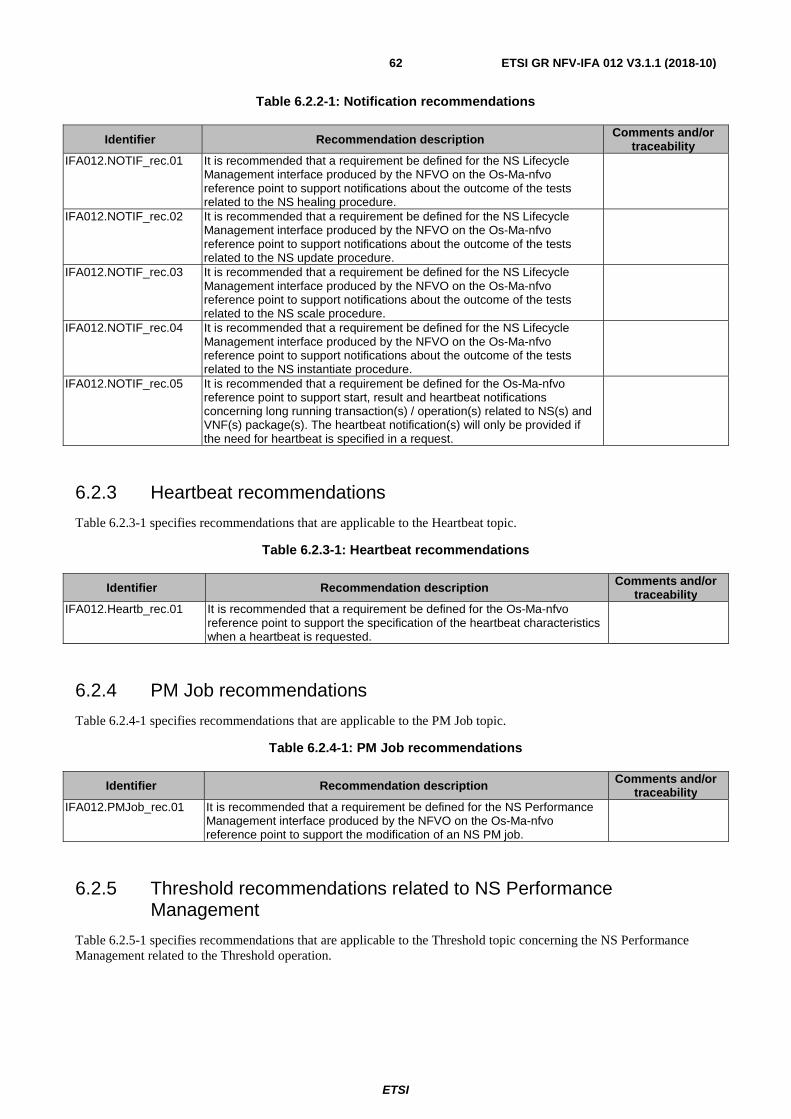
ETSI
ETSI GR NFV-IFA 012 V3.1.1 (2018-10) 62
Table 6.2.2-1: Notification recommendations
Identifier Recommendation description Comments and/or traceability
IFA012.NOTIF_rec.01
It is recommended that a requirement be defined for the NS Lifecycle Management interface produced by the NFVO on the Os-Ma-nfvo reference point to support notifications about the outcome of the tests related to the NS healing procedure.
IFA012.NOTIF_rec.02
It is recommended that a requirement be defined for the NS Lifecycle Management interface produced by the NFVO on the Os-Ma-nfvo reference point to support notifications about the outcome of the tests related to the NS update procedure.
IFA012.NOTIF_rec.03
It is recommended that a requirement be defined for the NS Lifecycle Management interface produced by the NFVO on the Os-Ma-nfvo reference point to support notifications about the outcome of the tests related to the NS scale procedure.
IFA012.NOTIF_rec.04
It is recommended that a requirement be defined for the NS Lifecycle Management interface produced by the NFVO on the Os-Ma-nfvo reference point to support notifications about the outcome of the tests related to the NS instantiate procedure.
IFA012.NOTIF_rec.05
It is recommended that a requirement be defined for the Os-Ma-nfvo reference point to support start, result and heartbeat notifications concerning long running transaction(s) / operation(s) related to NS(s) and VNF(s) package(s). The heartbeat notification(s) will only be provided if the need for heartbeat is specified in a request.
6.2.3 Heartbeat recommendations
Table 6.2.3-1 specifies recommendations that are applicable to the Heartbeat topic.
Table 6.2.3-1: Heartbeat recommendations
Identifier Recommendation description Comments and/or traceability
IFA012.Heartb_rec.01
It is recommended that a requirement be defined for the Os-Ma-nfvo reference point to support the specification of the heartbeat characteristics when a heartbeat is requested.
6.2.4 PM Job recommendations
Table 6.2.4-1 specifies recommendations that are applicable to the PM Job topic.
Table 6.2.4-1: PM Job recommendations
Identifier Recommendation description Comments and/or traceability
IFA012.PMJob_rec.01
It is recommended that a requirement be defined for the NS Performance Management interface produced by the NFVO on the Os-Ma-nfvo reference point to support the modification of an NS PM job.
6.2.5 Threshold recommendations related to NS Performance Management
Table 6.2.5-1 specifies recommendations that are applicable to the Threshold topic concerning the NS Performance Management related to the Threshold operation.

ETSI
ETSI GR NFV-IFA 012 V3.1.1 (2018-10) 63
Table 6.2.5-1: Threshold recommendations related to NS Performance Management
Identifier Recommendation description Comments and/or traceability
IFA012.Thres_rec.01
It is recommended that a requirement be defined for NS Performance Management interface produced by the NFVO on the Os-Ma-nfvo reference point to support the modification of NS PM thresholds.
6.2.6 General interface recommendations for the Os-Ma-Nfvo reference point
Table 6.2.6-1 specifies general Os-Ma-Nfvo recommendations.
Table 6.2.6-1: General Os-Ma-Nfvo recommendations
Identifier Recommendation description Comments and/or traceability
IFA012.GOSMA_rec.01
It is recommended that a requirement be defined for the NFVO to be capable of processing multiple requests over the Os-Ma-Nfvo interface from OSS/BSS in parallel.
IFA012.GOSMA_rec.02
It is recommended that a requirement be defined for the NFVO to be capable of validating an NS instantiation request against the onboarded NSD.
IFA012.GOSMA_rec.03
It is recommended that a requirement be defined for the NFVO to be capable of validating an NS update request against the onboarded NSD.
IFA012.GOSMA_rec.04
It is recommended that a requirement be defined for the NFVO to be capable of validating an NS scale request against the onboarded NSD.
IFA012.GOSMA_rec.05 It is recommended that a requirement be defined for the NFVO to be capable of validating an NS terminate request against the onboarded NSD.
IFA012.GOSMA_rec.06 It is recommended that a requirement be defined for the NFVO to be capable of validating an NS heal request against the onboarded NSD.
IFA012.GOSMA_rec.07 It is recommended that a requirement be defined for the NFVO to be capable of validating an NS query request against the onboarded NSD.
IFA012.GOSMA_rec.08 It is recommended that a requirement be defined for the NFVO to be capable of validating an NS delete request against the onboarded NSD.
IFA012.GOSMA_rec.09 The Delete NSD operation should be able to handle a list of NSD Ids.

ETSI
ETSI GR NFV-IFA 012 V3.1.1 (2018-10) 64
Annex A (informative): NS Nesting
A.1 Overview of Nested NSs In figure A.1-1, five NSs are shown. The circles are Service Access Points (SAPs) to the NS (i.e. SAPs are essentially Connection Points (CP) on the boundary of the NS). The dashed line represents the boundary of one NFVO's area of responsibility / control / management. There is one NSD for each type of NS. For the sake of argument, it is assumed that each NS in the figure is of a different type. So, five NSDs are in play here.
Figure A.1-1: NSs within an NFVO
In figure A.1-2, a consumer of the NFVO (an OSS/BSS Functional Block (FB) or another higher-tier NFVO) requests that the NFVO interconnect NS A, NS C and NS D as shown in the figure, using specific VLs that are defined by the consumer. The consumer also connects the external SAPs of NS A and NS D to some external entities. Further, the consumer instructs the NFVO to interconnect NS B and NS E, with the SAPs of NS B and NS E being connected to entities external to the view of the NFVO.
Some key points:
• The NFVO has no idea about the intended function of the two sets of concatenated NSs, i.e. the set of NS A, NS C and NS D, and the set of NS B and NS E.
• The NFVO does have an NSD for each of NSs in the concatenation but the NFVO does not have an NSD for the composition of the concatenated NSs.
In this case (and from the perspective of the NFVO), the interconnected NSs are referred to as being concatenated.
Network Service A
Network Service C
Network Service D
Network Service B
Network Service E

ETSI
ETSI GR NFV-IFA 012 V3.1.1 (2018-10) 65
Figure A.1-2: Concatenated NSs
In figure A.1-3, the NS types (of which NS A, NS C and NS D are instances) are combined / nested into a new NS type. NS F is an instance of this new NS type, called a composite NS type. The NS types (of which NS A, NS C and NS D are instances) are called nested NS type. The new NS type does have an NSD (call it NSD F) that is maintained by the NFVO and is onboarded with regard to the NFVO. NSD F will reference other NSDs (for the components that comprise the composite NS) and possibly VNFDs. Several levels of recursion are possible with regard to NS nesting.
Figure A.1-3: Nested NSs
Network Service A
Network Service C
Network Service D
Network Service B
Network Service E
Network Service B
Network Service E
Network Service F

ETSI
ETSI GR NFV-IFA 012 V3.1.1 (2018-10) 66
It is possible to have concatenated NSs at one layer (as exposed by a given NFVO) but for the consumer of the concatenated NSs to, in turn, re-expose this as one composite NS to its consumer. For example, one NFVO exposes the situation shown in figure A.1-2, and a consumer of that NFVO (say another NFVO) exposes the situation in figure A.1-3 (basically, hiding the internal details of NS F but simply re-exposing concatenated NS consisting of NS B and NS E as it is).
A.2 Principles concerning Nested NS Based on an analysis of the preceding scenarios in this annex, the following general principles have been identified:
1) Nesting within a composite NS should be acyclic (i.e. no loops).
2) A given NS may be nested (and thus shared) by several composite NSs.
3) The nested NSs within a composite NS are not necessarily adjacent.
A.3 Composite vCDN Example Consider a virtual Content Delivery Network (vCDN) NS that is comprised of two nested vCDN NSs (perhaps each one in a different data center). The overall vCDN is NS D in the following figure, and the two nested vCDNs are NS A and NS C. Further, NS B adds special security features to NS A.
The VNFs supporting NS A and C are virtual Content Servers (vCSs). The VNF supporting NS B provides various security functions such as encryption.
The nesting hierarchy is as follows:
• NS D:
- NS A:
various VNFs (vCSs)
NS B
various VNFs (security VNF)
- NS C:
various VNFs (vCSs)
Figure A.3-1

ETSI
ETSI GR NFV-IFA 012 V3.1.1 (2018-10) 67
A.4 Virtual Customer Premises Equipment (vCPE) NS Example with Connectivity
In this example, an instance of vCPE NS is composed of two nested NSs, i.e.
• A shared NS that supports IaaS (NS A in the following figure)
• A dedicated NS that supports Platform as a Service (PaaS) beyond what is already provided by the Infrastructure as a Service (IaaS) component (NS B in the following figure)
In addition to and independent of connectivity between the constituent VNFs for each nested NS, there is also a need to connect the two nested NSs directly.
For this example, it is assumed that the NSs (i.e. vCPE and its two components a shared Iaas NS and a dedicated PaaS NS provide logic beyond that in the constituent VNFs). So, the vCPE (for this example) is more than just a chaining of the constituent VNFs and as such, needs to be supported by a Virtual Machine (VM) (or VMs). VNF X provides computing resources for the execution of NS D, A and C.
Figure A.4-1
The nesting hierarch is as follows:
• NS D (vCPE NS):
- NS A (IaaS NS - shared nested NS in support of several vCPE NS instances):
VNFs A, B and C
- NS B (PaaS NS - dedicated NS in support of a given vCPE instance):
VNFs D, E, F and G
The line between NS A and NS C in the figure is meant to show adjacency (i.e. the ability to communicate) between the two nested NSs. In this case, the communication is actually internal to VNF X.
The following steps are followed in the instantiation of NS D:
1) Assuming a bottom-up approach, NS A is instantiated (possibly with no VNFs and/or some references to existing VNFs to be re-used).
2) Any additional VNFs (beyond those referenced in the first step) are instantiated. The NFVO makes VNF instantiation requests to the VNFM.
3) The VNFM successfully instantiates VNFs A, B and C, and responds back to the NFVO.

ETSI
ETSI GR NFV-IFA 012 V3.1.1 (2018-10) 68
4) The NFVO queries the VNFM for the details of VNFs A, B and C. In particular, the NFVO needs to know the external Connection Points (CPs) for each VNF.
5) The NFVO requests that the Virtualised Infrastructure Manager (VIM) create connectivity between VNFs A, B and C (as shown in the figure). It is assumed that VNFs A, B and C can be supported by a single VIM.
a) First, the NFVO sends an Allocate Virtualised Network Resource request to the VIM with the networkResourceType set to "network" (only one virtual network is created).
b) Next, the NFVO uses the Allocate Virtualised Network Resource operation to create ports on the virtual network, corresponding to the CPs on the VNFs that are to be connected (small black dots in the figure A.4-1).
6) A similar set of steps is employed to instantiate NS C. It is assumed that VNFs D, E, F and G can be supported by a single VIM.
7) If VNF C and D are supported by different VIMs, there is currently no standard way (in ETSI NFV specs) for the NFVO to connect the two VNFs.
8) Independent of the VNF connectivity, NS A and C need to be connected. If NS A and C can be supported by the same VIM as VNFs A, B and C, the NFVO can use a similar procedure as to that in Step 4 to interconnect NS A and C (could even possibly use the same virtual network with additional ports and segments).
Alternately, the virtual networks could be created first, followed by VNF instantiation and then creation of the ports.
A.5 Geographically Distributed virtual Content Delivery Network (vCDN) Example
In this example, a vCDN NS is distributed over several geographic areas. The following assumptions are made:
• The vCDN capability is provided across several geographic areas (referred to as "regions" in the figure below).
• A given instance of vCDN (for a particular consumer) is represented as a composite NS with nested NSs in each region.
• The constituent VNFs (e.g. virtual Content Servers) are likely to be shared by several instances of vCDN NS.
• Only the application-neutral aspects of vCDN NS are considered here.
In this example, an instance of vCDN NS (NS A in the following figure) orchestrates vCDN across several regions (all within one service provider). NS A, in turn, is composed of NS B (in Region X) and NS C (in Region Y). For the sake of simplicity, assume each region in this example is supported by a single Network Functions Virtualisation Infrastructure (NFVI) Point of Presence (PoP), one VNFM and one NFVO.
• NS B is, in turn, composed of NS D and E (both vCDN NSs).
• NS C is, in turn, composed of NS G and H (also vCDN NSs).
• VNF A, B and C provide service orchestration logic in support of vCDN and routing capabilities. VNF A, B and C provide capabilities that can be shared by multiple NS instances. To be clear, the logic needed to support NS A (beyond that in its components) resides in VNF A. Similar statements can be made for NS B and VNF B, and NS C and VNF C. The view taken here is that an NS is nothing more than the sum of its parts, i.e. the constituent VNFs and nested NSs. In the case a VNF or NS is shared by several NSs, then the above statement needs to be qualified to refer to that part of the constituent (VNF or nested NS) that is dedicated/allocated to the given composite NS.
• VNFs A and B, VNFs A and C, and VNFs B and C are connected by VLs that provide protected connectivity (e.g. via diverse routing).
NS B and it components are in Region X, and NS C and its components are in Region Y. Communication between the two regions (in particular between VNFs B and C) may require route redundancy and additional security, e.g. in the case where another provider's network is required to interconnect between the two regions.

ETSI
ETSI GR NFV-IFA 012 V3.1.1 (2018-10) 69
Figure A.5-1
In this scenario, NS A represents an instance of vCDN for a given consumer. NS A keeps track of the VNF allocated to the consumer and has the intelligence to ensure the SLA with the consumer is honoured. The following steps are employed to instantiate NS A:
1) A consumer of the umbrella NFVO (see [NFVIFA009] concerning umbrella NFVOs) in Region Z makes a request for an instance of vCDN.
2) The NFVO decomposes the request and makes a request for a vCDN NS to the NFVO in Region X (this is shown as NS B in the figure A.5-1).
a) The NFVO in Region X requests that the VNFM in Region X instantiate VNF B.
b) The NFVO in Region X instantiates NS D and NS E.
c) The NFVO in Region X instantiates NS B using VNF B as a component, and NS D and E as nested NSs.
3) The umbrella NFVO in Region Z initiates a similar flow to instantiate NS C (which is carried out by the NFVO in Region Y). This can be done in parallel with Step #2.
4) In parallel with Steps #2 and #3, the umbrella NFVO in Region Z requests that the VNFM in Region Z instantiate VNF A.
5) The umbrella NFVO in Region Z instantiates NS A using VNF A as a component, and NS B and C as nested NSs.
6) Connectivity between VNF A and B, VNF A and C, and VNF B and C is established.
7) When all the above steps are completed successfully, the umbrella NFVO in Region Z responds back to the consumer.
A key point in this example is that an NS is assumed to be no more than the sum of its parts (VNFs and nested NSs). If additional intelligence is needed to orchestrate several components (VNFs and NSs) into a composite NS, then another VNF is designed to support the additional service orchestration capability and that VNF is then used as a component of the composite NS.
ETSI
ETSI GR NFV-IFA 012 V3.1.1 (2018-10) 70
Annex B (informative): Authors & contributors The following people have contributed to the present document:
Rapporteur:
Michael Klotz (Deutsche Telekom AG)
Other contributors:
Marc Flauw, Hewlett Packard Enterprise
Uwe Rauschenbach, Nokia
Dmytro Gassanov, NetCracker
Shitao Li, Huawei Tech. (UK) Co., Ltd
Stephen Fratini, Ericsson LM
Drew Jordan, Sigma Systems
Nicola Santinelli, Telecom Italia
Shelby Kiewel, iconectiv
Zarrar Yousaf, NEC Europe Ltd
Fabio Giust, NEC Europe Ltd

ETSI
ETSI GR NFV-IFA 012 V3.1.1 (2018-10) 71
Annex C: Bibliography
• ETSI GS NFV 001: "Network Functions Virtualisation (NFV); Use Cases".
• ETSI GS NFV 002: "Network Functions Virtualisation (NFV); Architectural Framework".
• ETSI GS NFV 004: "Network Functions Virtualisation (NFV); Virtualisation Requirements".
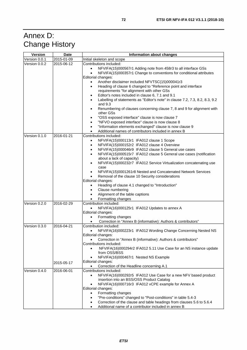
ETSI
ETSI GR NFV-IFA 012 V3.1.1 (2018-10) 72
Annex D: Change History
Version Date Information about changes Version 0.0.1 2015-01-09 Initial skeleton and scope Version 0.0.2 2015-06-12 Contributions included:
• NFVIFA(15)000567r1 Adding note from 458r3 to all interface GSs • NFVIFA(15)000357r1 Change to conventions for conditional attributes
Editorial changes: • Another disclaimer included NFVTSC(15)000041r3 • Heading of clause 6 changed to "Reference point and interface
requirements "for alignment with other GSs • Editor's notes included in clause 6, 7.1 and 9.1 • Labelling of statements as "Editor's note" in clause 7.2, 7.3, 8.2, 8.3, 9.2
and 9.3 • Renumbering of clauses concerning clause 7, 8 and 9 for alignment with
other GSs • "OSS exposed interface" clause is now clause 7 • "NFVO exposed interface" clause is now clause 8 • "Information elements exchanged" clause is now clause 9 • Additional names of contributors included in annex B
Version 0.1.0 2016-01-21 Contributions included: • NFVIFA(15)000113r1 IFA012 clause 1 Scope • NFVIFA(15)000152r2 IFA012 clause 4 Overview • NFVIFA(15)000046r9 IFA012 clause 5 General use cases • NFVIFA(15)000515r7 IFA012 clause 5 General use cases (notification
about a lack of capacity) • NFVIFA(15)000232r7 IFA012 Service Virtualization concatenating use
case • NFVIFA(15)0001261r8 Nested and Concatenated Network Services • Removal of the clause 10 Security considerations
Editorial changes: • Heading of clause 4.1 changed to "Introduction" • Clause numbering • Alignment of the table captions • Formatting changes
Version 0.2.0 2016-02-29 Contribution included: • NFVIFA(16)000125r1 IFA012 Updates to annex A
Editorial changes: • Formatting changes • Correction in "Annex B (informative): Authors & contributors"
Version 0.3.0 2016-04-21
2015-05-17
Contribution included: • NFVIFA(16)000223r1 IFA012 Wording Change Concerning Nested NS
Editorial changes: • Correction in "Annex B (informative): Authors & contributors"
Contributions included: • NFVIFA(16)000294r2 IFA012 5.11 Use Case for an NS instance update
from OSS/BSS • NFVIFA(16)000467r1 Nested NS Example
Editorial changes: • Correction of the Headline concerning A.1
Version 0.4.0 2016-06-01 Contributions included: • NFVIFA(16)000292r5 IFA012 Use Case for a new NFV based product
insertion into an BSS/OSS Product Catalog • NFVIFA(16)000716r3 IFA012 vCPE example for Annex A
Editorial changes: • Formatting changes • "Pre-conditions" changed to "Post-conditions" in table 5.4-3 • Correction of the clause and table headings from clauses 5.6 to 5.6.4 • Additional name of a contributor included in annex B
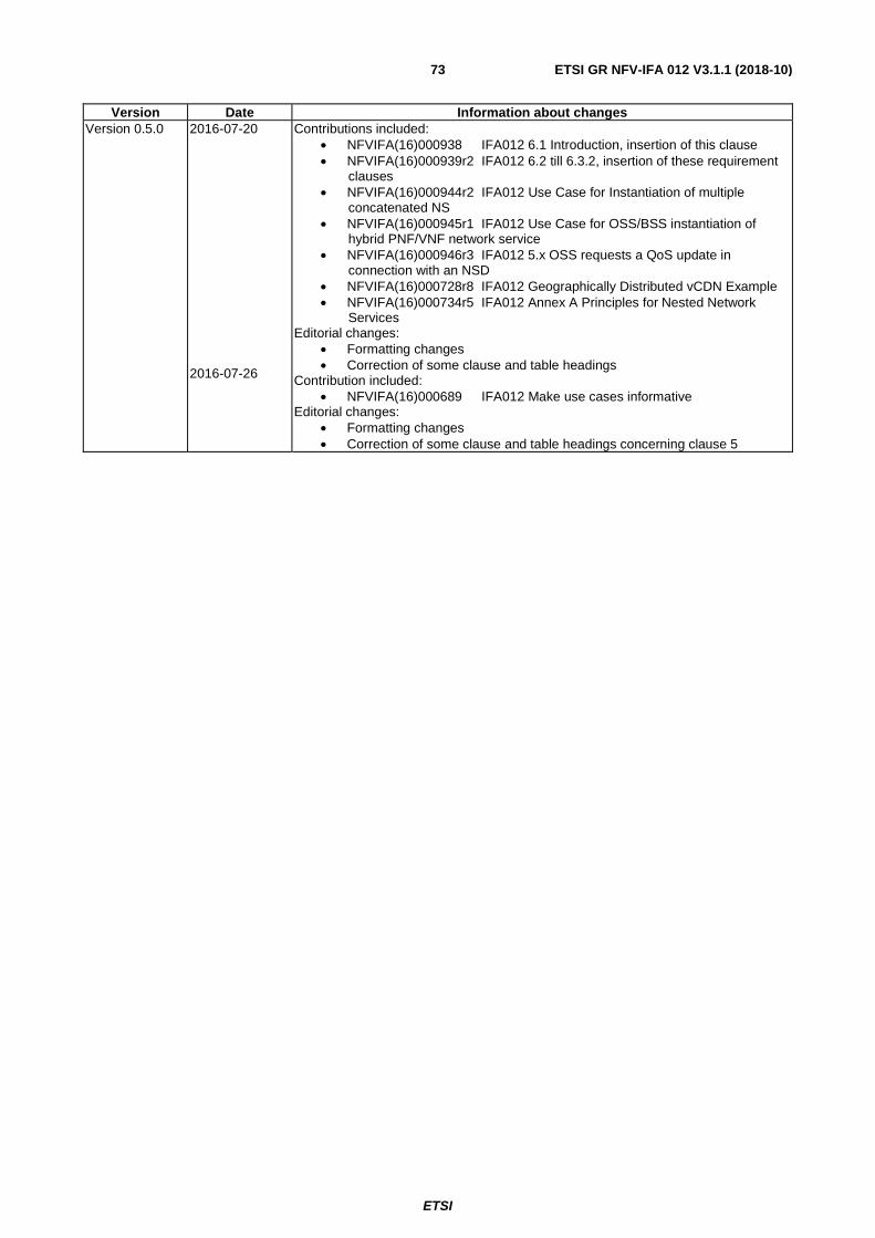
ETSI
ETSI GR NFV-IFA 012 V3.1.1 (2018-10) 73
Version Date Information about changes Version 0.5.0 2016-07-20
2016-07-26
Contributions included: • NFVIFA(16)000938 IFA012 6.1 Introduction, insertion of this clause • NFVIFA(16)000939r2 IFA012 6.2 till 6.3.2, insertion of these requirement
clauses • NFVIFA(16)000944r2 IFA012 Use Case for Instantiation of multiple
concatenated NS • NFVIFA(16)000945r1 IFA012 Use Case for OSS/BSS instantiation of
hybrid PNF/VNF network service • NFVIFA(16)000946r3 IFA012 5.x OSS requests a QoS update in
connection with an NSD • NFVIFA(16)000728r8 IFA012 Geographically Distributed vCDN Example • NFVIFA(16)000734r5 IFA012 Annex A Principles for Nested Network
Services Editorial changes:
• Formatting changes • Correction of some clause and table headings
Contribution included: • NFVIFA(16)000689 IFA012 Make use cases informative
Editorial changes: • Formatting changes • Correction of some clause and table headings concerning clause 5

ETSI
ETSI GR NFV-IFA 012 V3.1.1 (2018-10) 74
Version Date Information about changes Version 0.5.1 2016-07-26
Sentence "All the use cases presented in this clause are informative." Included in clause "5.1 Introduction" based on the contribution NFVIFA(16)000689.
Version 0.5.2 2016-08-01
2016-08-31 2016-09-05
Editorial Changes: • Align description of use cases to agreed template using sub-headers • Formatting changes • Apply the convention for abbreviations based on NFVIFA(16)000922r6
Editorial Changes: • Formatting changes • Correction of some clause and table headings concerning clause 5 • Orthographical corrections • Content of the clause "Abbreviations" extended. In addition to that the
necessary extensions within the text included. Editorial Changes:
• Content of the clause "Abbreviations" reduced because these abbreviations are referenced via ETSI GS NFV 003. Based on that the necessary extensions have been adjusted in the clauses 4.1 and 5.2.1.
Version 0.6.0 2016-10-16 Contributions included: • NFVIFA(16)000634r8 IFA012 E2E service healing • NFVIFA(16)0001123r8 IFA012 5.x Use Case for Configuration of VNF from
OSS • NFVIFA(16)0001277r1 IFA012 Use Case for End to End Service
Termination Editorial Changes:
• Formatting changes • Correction of some clause and table headings concerning clause 5 • Orthographical corrections • Content of the clause "Abbreviations" extended
Version 0.7.0 2016-11-07
2016-11-09
Contributions included: • NFVIFA(16)000635r5 IFA012 - E2E service definition • NFVIFA(16)0001371r3 IFA012 Structural changes for the IFA012 GS new
clause 7 and further subclauses including content proposed • NFVIFA(16)0001374r2 IFA012 7.3.x Delete NSD operation
recommendations Editorial Changes:
• Formatting changes • Correction of some clause and table headings concerning clauses 7, 8, 9,
and 10 • Additional name of a contributor included in annex B.
Editorial Changes: • Formatting changes concerning clauses 5.15, 5.16, 5.17, and in the
table 7.3.2-1 • Additional name of a contributor included in annex B.
Version 0.8.0 2017-01-11 Contributions included: • NFVIFA(16)0001366r2 IFA012 6.3.x Test requirements • NFVIFA(16)0001367r2 IFA012 6.3.x Notification requirements • NFVIFA(16)0001364r3 IFA012 Use case for switching from active Ns
instances based on several NSDa versions to newly created and instantiated NSb instances
• NFVIFA(16)0001376r4 IFA012 Use case for deletion of NSD by OSS • NFVIFA(16)0001377r4 IFA012 Use case for deletion of a specific version of
NSD by OSS • NFVIFA(16)0001472r1 IFA012 Use case for partial failure of instantiation
request for a concatenated service • NFVIFA(16)0001494r3 IFA012 Use case for OSS requesting an NS Scale
In Editorial Changes:
• Formatting changes • Orthographical corrections • Correction of some clause and table headings concerning clauses 5, 6, and
7 • Title 1 of the document adapted.
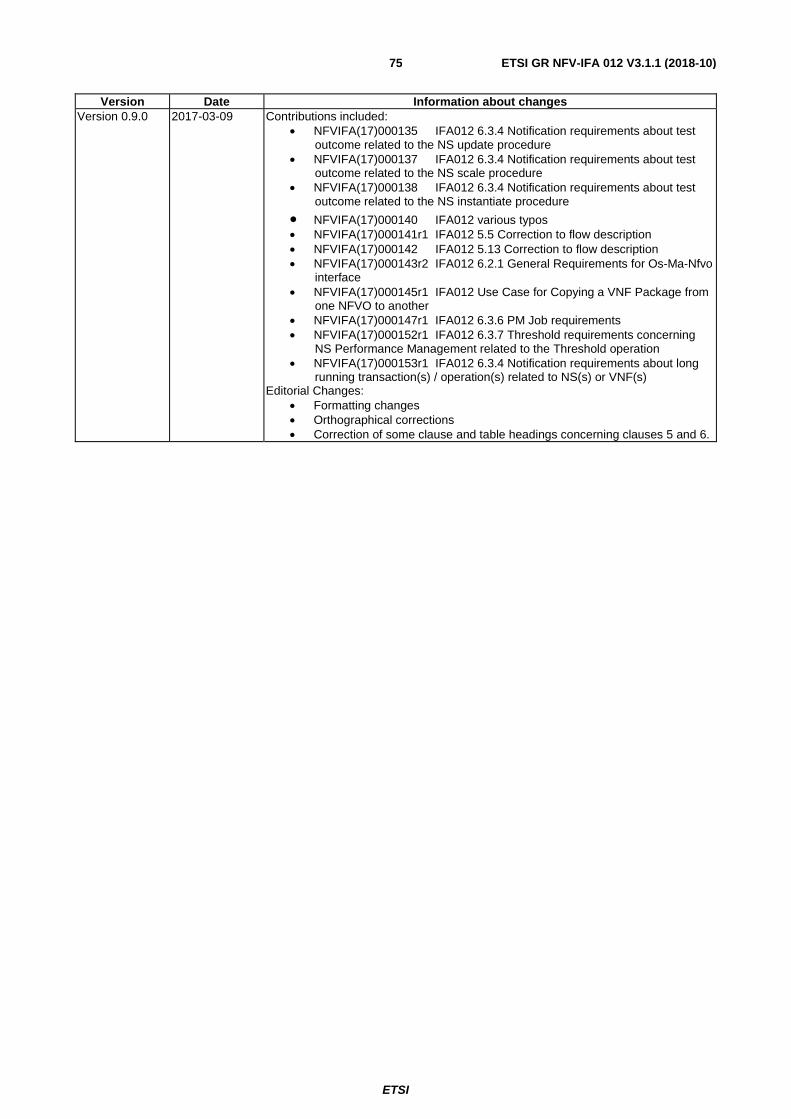
ETSI
ETSI GR NFV-IFA 012 V3.1.1 (2018-10) 75
Version Date Information about changes Version 0.9.0 2017-03-09
Contributions included: • NFVIFA(17)000135 IFA012 6.3.4 Notification requirements about test
outcome related to the NS update procedure • NFVIFA(17)000137 IFA012 6.3.4 Notification requirements about test
outcome related to the NS scale procedure • NFVIFA(17)000138 IFA012 6.3.4 Notification requirements about test
outcome related to the NS instantiate procedure
• NFVIFA(17)000140 IFA012 various typos • NFVIFA(17)000141r1 IFA012 5.5 Correction to flow description • NFVIFA(17)000142 IFA012 5.13 Correction to flow description • NFVIFA(17)000143r2 IFA012 6.2.1 General Requirements for Os-Ma-Nfvo
interface • NFVIFA(17)000145r1 IFA012 Use Case for Copying a VNF Package from
one NFVO to another • NFVIFA(17)000147r1 IFA012 6.3.6 PM Job requirements • NFVIFA(17)000152r1 IFA012 6.3.7 Threshold requirements concerning
NS Performance Management related to the Threshold operation • NFVIFA(17)000153r1 IFA012 6.3.4 Notification requirements about long
running transaction(s) / operation(s) related to NS(s) or VNF(s) Editorial Changes:
• Formatting changes • Orthographical corrections • Correction of some clause and table headings concerning clauses 5 and 6.

ETSI
ETSI GR NFV-IFA 012 V3.1.1 (2018-10) 76
Version Date Information about changes Version 0.10.0 2017-09-04
Contributions included: • NFVIFA(17)000127 IFA012 5.2 NS lifecycle management in Broadband
Network concerning NOTEs and Editor's note • NFVIFA(17)000129r3 IFA012 6.3.3 Test requirements; Additional test
requirements for Update NS operation • NFVIFA(17)000131r3 IFA012 6.3.3 Test requirements; Test requirements
related to Scale NS operation • NFVIFA(17)000132r2 IFA012 6.3.3 Test requirements; Additional test
requirement related to the NS healing procedure • NFVIFA(17)000133r2 IFA012 6.3.3 Test requirements; Test requirements
related to the instantiate NS procedure • -NFVIFA(17)000232r1 IFA012 5.2 NS lifecycle management in Broadband
Network concerning modifications in the pre-conditions and the base flow • NFVIFA(17)000233r1 IFA012 6.3.8 General interface requirements for the
Os-Ma-Nfvo reference point related to a validation procedure connected to an NS update request
• NFVIFA(17)000235r2 IFA012 6.3.8 General interface requirements for the Os-Ma-Nfvo reference point related to a validation procedure
• NFVIFA(17)000239r1 IFA012 6.3.4 Notification requirements related to an NFVO validation procedure
• NFVIFA(16)000296r9 IFA012 5.22 Use case for an Application Function overlaying the NFV ecosystem
• NFVIFA(17)000248r3 IFA012 6.3.x Requirements for approval / disapproval concerning LCM operation(s) of the NFVO in connection with OSS/BSS
• NFVIFA(17)000422 IFA012 6.3.8 General interface requirements for the Os-Ma-Nfvo reference point related to a validation procedure connected to an NS scale request
• NFVIFA(17)000423 IFA012 6.3.8 General interface requirements for the Os-Ma-Nfvo reference point related to a validation procedure connected to an NS terminate request
• NFVIFA(17)000424 IFA012 6.3.8 General interface requirements for the Os-Ma-Nfvo reference point related to a validation procedure connected to an NS heal request
• NFVIFA(17)000425 IFA012 6.3.8 General interface requirements for the Os-Ma-Nfvo reference point related to a validation procedure connected to an NS query request
• NFVIFA(17)000426r1 IFA012 6.3.8 General interface requirements for the Os-Ma-Nfvo reference point related to a validation procedure connected to an NS delete request
• NFVIFA(17)000429 IFA012 6.3.4 Notification requirements related to an NFVO validation procedure concerning the NS update request
• NFVIFA(17)000430 IFA012 6.3.4 Notification requirements related to an NFVO validation procedure concerning the NS scale request
• NFVIFA(17)000431 IFA012 6.3.4 Notification requirements related to an NFVO validation procedure concerning the NS terminate request
• NFVIFA(17)000432 IFA012 6.3.4 Notification requirements related to an NFVO validation procedure concerning the NS heal request
Version 0.10.0 2017-09-04
• NFVIFA(17)000433 IFA012 6.3.4 Notification requirements related to an NFVO validation procedure concerning the NS query request
• NFVIFA(17)000434 IFA012 6.3.4 Notification requirements related to an NFVO validation procedure concerning the NS delete request
Editorial Changes: • Formatting changes • Orthographical corrections • Correction of some clause and table headings concerning clauses 5 and 6. • Additional names of contributors included in annex B.

ETSI
ETSI GR NFV-IFA 012 V3.1.1 (2018-10) 77
Version Date Information about changes Version 0.11.0 2017-09-14 Contributions included:
• NFVIFA(17)000829 IFA012 Removal of the clause 6.3.1 VNFD management requirements
• NFVIFA(17)000830 IFA012 Removal of the clause 6.3.2 VNF package management interface requirements
• NFVIFA(17)000831 IFA012 Removal of the clause 7.3.1 Terminate N operation recommendations
• NFVIFA(17)000832 IFA012 Removal of the clause 8 OSS exposed interfaces including subclauses
• NFVIFA(17)000833 IFA012 Removal of the clause 10 Information elements exchanged including subclauses
• NFVIFA(17)000834 IFA012 Modification of the clause 9 NFVO exposed interfaces including subclauses
Editorial Changes: • Formatting changes • Correction of some clause and table headings concerning clauses 6, 7, and
8. Version 0.12.0 2018-03-16 Contributions included:
• NFVIFA(18)000136r1 IFA012 Updating scope clause • NFVIFA(18)000137r3 IFA012 Updates to Clause 4 • NFVIFA(18)000147r1 IFA012 Update to clause 5.1 • NFVIFA(18)000149 IFA012 Removal of clause 7 Reference point and
interface recommendations including subclauses • NFVIFA(18)000150r2 IFA012 Change of clause numbering concerning
clause 8 including subclauses • NFVIFA(18)000175r1 IFA012 Restate Requirements as
Recommendations • NFVIFA(18)000179 IFA012 Changing Normative text to Informative • NFVIFA(18)000183r1 IFA012 Change document Title and convert from
GS to GR • NFVIFA(18)000709 IFA012 adding back an incorrectly removed
recommendation Version 0.13.0 2018-09-19 Editorial Changes:
• Removal of Editor Notes prior to WG submission • Renumbering of clause 6.2.7 to 6.2.6 as a result of handling editorial note • Renew of TOC
Version 0.13.1 2018-09-25 Editorial Changes: • Changing occurrences of "must" to will or can

ETSI
ETSI GR NFV-IFA 012 V3.1.1 (2018-10) 78
History
Document history
V3.1.1 October 2018 Publication