etsi ts 125 331 v3.3 · 3g ts 25.331 version 3.3.0 release 1999 etsi ts 125 331 v3.3.0 (2000-06)...
TRANSCRIPT

ETSI TS 125 331 V3.3.0 (2000-06)Technical Specification
Universal Mobile Telecommunications System (UMTS);RRC Protocol Specification
(3G TS 25.331 version 3.3.0 Release 1999)

1
ETSI
ETSI TS 125 331 V3.3.0 (2000-06)3G TS 25.331 version 3.3.0 Release 1999
ReferenceRTS/TSGR-0225331UR2
KeywordsUMTS
ETSI
650 Route des LuciolesF-06921 Sophia Antipolis Cedex - FRANCE
Tel.: +33 4 92 94 42 00 Fax: +33 4 93 65 47 16
Siret N° 348 623 562 00017 - NAF 742 CAssociation à but non lucratif enregistrée à laSous-Préfecture de Grasse (06) N° 7803/88
Important notice
Individual copies of the present document can be downloaded from:http://www.etsi.org
The present document may be made available in more than one electronic version or in print. In any case of existing orperceived difference in contents between such versions, the reference version is the Portable Document Format (PDF).
In case of dispute, the reference shall be the printing on ETSI printers of the PDF version kept on a specific networkdrive within ETSI Secretariat.
Users of the present document should be aware that the document may be subject to revision or change of status.Information on the current status of this and other ETSI documents is available at http://www.etsi.org/tb/status/
If you find errors in the present document, send your comment to:[email protected]
Copyright Notification
No part may be reproduced except as authorized by written permission.The copyright and the foregoing restriction extend to reproduction in all media.
© European Telecommunications Standards Institute 2000.
All rights reserved.

2
ETSI
ETSI TS 125 331 V3.3.0 (2000-06)3G TS 25.331 version 3.3.0 Release 1999
Intellectual Property RightsIPRs essential or potentially essential to the present document may have been declared to ETSI. The informationpertaining to these essential IPRs, if any, is publicly available for ETSI members and non-members, and can be foundin ETSI SR 000 314: "Intellectual Property Rights (IPRs); Essential, or potentially Essential, IPRs notified to ETSI inrespect of ETSI standards", which is available from the ETSI Secretariat. Latest updates are available on the ETSI Webserver (http://www.etsi.org/ipr).
Pursuant to the ETSI IPR Policy, no investigation, including IPR searches, has been carried out by ETSI. No guaranteecan be given as to the existence of other IPRs not referenced in ETSI SR 000 314 (or the updates on the ETSI Webserver) which are, or may be, or may become, essential to the present document.
ForewordThis Technical Specification (TS) has been produced by the ETSI 3rd Generation Partnership Project (3GPP).
The present document may refer to technical specifications or reports using their 3GPP identities, UMTS identities orGSM identities. These should be interpreted as being references to the corresponding ETSI deliverables.
The cross reference between GSM, UMTS, 3GPP and ETSI identities can be found under www.etsi.org/key .

ETSI
3G TS 25.331 version 3.3.0 Release 1999 3 ETSI TS 125 331 V3.3.0 (2000-06)
Contents
Foreword .......................................................................................................................................................... 20
1 Scope...................................................................................................................................................... 21
2 References.............................................................................................................................................. 21
3 Definitions and abbreviations ................................................................................................................ 213.1 Definitions ....................................................................................................................................................... 213.2 Abbreviations................................................................................................................................................... 22
4 General................................................................................................................................................... 23
5 RRC Services provided to upper layers ................................................................................................. 26
6 Services expected from lower layers ..................................................................................................... 266.1 Services expected from Layer 2....................................................................................................................... 266.2 Services expected from Layer 1....................................................................................................................... 26
7 Functions of RRC .................................................................................................................................. 26
8 RRC procedures..................................................................................................................................... 278.1 RRC Connection Management Procedures...................................................................................................... 278.1.1 Broadcast of system information................................................................................................................ 278.1.1.1 General ................................................................................................................................................. 278.1.1.1.1 System information structure .......................................................................................................... 278.1.1.1.2 System information blocks.............................................................................................................. 288.1.1.1.3 Segmentation and concatenation of system information blocks ..................................................... 318.1.1.1.4 Re-assembly of segments................................................................................................................ 328.1.1.1.5 Scheduling of system information .................................................................................................. 328.1.1.2 Initiation ............................................................................................................................................... 328.1.1.3 Reception of SYSTEM INFORMATION messages by the UE ........................................................... 328.1.1.3.1 Reception of SYSTEM INFORMATION messages broadcast on a BCH transport channel ......... 338.1.1.3.2 Reception of SYSTEM INFORMATION messages broadcast on a FACH transport channel....... 338.1.1.4 Modification of system information ..................................................................................................... 338.1.1.4.1 Modification of system information blocks using a value tag ........................................................ 348.1.1.4.2 Modification of system information without value tag ................................................................... 348.1.1.4.3 Time critical modification of system information blocks ............................................................... 348.1.1.5 Actions upon reception of system information blocks ......................................................................... 358.1.1.5.1 System Information Block type 1 ................................................................................................... 358.1.1.5.2 System Information Block type 2 ................................................................................................... 358.1.1.5.3 System Information Block type 3 ................................................................................................... 368.1.1.5.4 System Information Block type 4 ................................................................................................... 368.1.1.5.5 System Information Block type 5 ................................................................................................... 368.1.1.5.6 System Information Block type 6 ................................................................................................... 368.1.1.5.7 System Information Block type 7 ................................................................................................... 378.1.1.5.8 System Information Block type 8 ................................................................................................... 378.1.1.5.9 System Information Block type 9 ................................................................................................... 378.1.1.5.10 System Information Block type 10 ................................................................................................. 378.1.1.5.11 System Information Block type 11 ................................................................................................. 378.1.1.5.12 System Information Block type 12 ................................................................................................. 388.1.1.5.13 System Information Block type 13 ................................................................................................. 398.1.1.5.14 System Information Block type 14 ................................................................................................. 398.1.1.5.15 System Information Block type 15 ................................................................................................. 408.1.1.5.16 System Information Block type 16 ................................................................................................. 418.1.2 Paging......................................................................................................................................................... 418.1.2.1 General ................................................................................................................................................. 428.1.2.2 Initiation ............................................................................................................................................... 428.1.2.3 Reception of an PAGING TYPE 1 message by the UE ....................................................................... 428.1.3 RRC connection establishment .................................................................................................................. 438.1.3.1 General ................................................................................................................................................. 43

ETSI
3G TS 25.331 version 3.3.0 Release 1999 4 ETSI TS 125 331 V3.3.0 (2000-06)
8.1.3.2 Initiation ............................................................................................................................................... 438.1.3.3 Reception of an RRC CONNECTION REQUEST message by the UTRAN ...................................... 438.1.3.4 Reception of a RRC CONNECTION SETUP message by the UE ...................................................... 448.1.3.5 Physical channel failure or T300 timeout ............................................................................................. 448.1.3.6 Invalid RRC CONNECTION SETUP message ................................................................................... 458.1.3.7 Reception of an RRC CONNECTION REJECT message by the UE .................................................. 458.1.3.8 Invalid RRC CONNECTION REJECT message ................................................................................. 468.1.3.9 Reception of an RRC CONNECTION SETUP COMPLETE message by the UTRAN ...................... 468.1.4 RRC connection release ............................................................................................................................. 478.1.4.1 General ................................................................................................................................................. 478.1.4.2 Initiation ............................................................................................................................................... 478.1.4.3 Reception of an RRC CONNECTION RELEASE message by the UE ............................................... 478.1.4.4 Invalid RRC CONNECTION RELEASE message .............................................................................. 478.1.4.5 Expiry of timer T308 in CELL_DCH state .......................................................................................... 488.1.4.6 Successful transmission of the RRC CONNECTION RELEASE COMPLETE message in
CELL_FACH state ............................................................................................................................... 488.1.4.7 Reception of an RRC CONNECTION RELEASE COMPLETE message by UTRAN....................... 488.1.4.8 Unsuccessful transmission of the RRC CONNECTION RELEASE COMPLETE message in
CELL_FACH state ............................................................................................................................... 488.1.4.9 Detection of dedicated physical channel release by UTRAN in CELL_DCH state ............................. 488.1.4.10 No reception of an RRC CONNECTION RELEASE COMPLETE message by UTRAN .................. 488.1.5 RRC connection re-establishment .............................................................................................................. 488.1.5.1 General ................................................................................................................................................. 498.1.5.2 Initiation ............................................................................................................................................... 498.1.5.3 Detection of "in service area" ............................................................................................................... 498.1.5.4 Reception of an RRC CONNECTION RE-ESTABLISHMENT REQUEST message by the
UTRAN ................................................................................................................................................ 508.1.5.5 Reception of an RRC CONNECTION RE-ESTABLISHMENT message by the UE.......................... 508.1.5.6 T314 timeout ........................................................................................................................................ 518.1.5.7 T315 timeout ........................................................................................................................................ 518.1.5.8 Invalid RRC CONNECTION RE-ESTABLISHMENT message ........................................................ 518.1.5.9 T301 timeout or DPCH failure ............................................................................................................. 528.1.5.10 Reception of an RRC CONNECTION RE-ESTABLISHMENT COMPLETE message by the
UTRAN ................................................................................................................................................ 528.1.6 Transmission of UE capability information ............................................................................................... 528.1.6.1 General ................................................................................................................................................. 538.1.6.2 Initiation ............................................................................................................................................... 538.1.6.3 Reception of an UE CAPABILITY INFORMATION message by the UTRAN ................................. 538.1.6.4 Reception of the UE CAPABILITY INFORMATION CONFIRM message by the UE ..................... 538.1.6.5 Invalid UE CAPABILITY INFORMATION CONFIRM message...................................................... 538.1.6.6 T304 timeout ........................................................................................................................................ 538.1.7 UE capability enquiry................................................................................................................................. 548.1.7.1 General ................................................................................................................................................. 548.1.7.2 Initiation ............................................................................................................................................... 548.1.7.3 Reception of an UE CAPABILITY ENQUIRY message by the UE.................................................... 548.1.7.4 Invalid UE CAPABILITY ENQUIRY message................................................................................... 548.1.8 Initial Direct transfer .................................................................................................................................. 548.1.8.1 General ................................................................................................................................................. 558.1.8.2 Initiation of Initial direct transfer procedure in the UE ........................................................................ 558.1.8.3 Reception of INITIAL DIRECT TRANSFER message by the UTRAN ............................................. 558.1.9 Downlink Direct transfer............................................................................................................................ 558.1.9.1 General ................................................................................................................................................. 568.1.9.2 Initiation of downlink direct transfer procedure in the UTRAN........................................................... 568.1.9.3 Reception of a DOWNLINK DIRECT TRANSFER message by the UE............................................ 568.1.9.4 Invalid DOWNLINK DIRECT TRANSFER message......................................................................... 568.1.10 Uplink Direct transfer................................................................................................................................. 578.1.10.1 General ................................................................................................................................................. 578.1.10.2 Initiation of uplink direct transfer procedure in the UE........................................................................ 578.1.10.3 Reception of UPLINK DIRECT TRANSFER message by the UTRAN ............................................. 578.1.11 UE dedicated paging .................................................................................................................................. 588.1.11.1 General ................................................................................................................................................. 588.1.11.2 Initiation ............................................................................................................................................... 58

ETSI
3G TS 25.331 version 3.3.0 Release 1999 5 ETSI TS 125 331 V3.3.0 (2000-06)
8.1.11.3 Reception of an PAGING TYPE 2 message by the UE ....................................................................... 588.1.11.4 Invalid PAGING TYPE 2 message ...................................................................................................... 588.1.12 Security mode control ................................................................................................................................ 598.1.12.1 General ................................................................................................................................................. 598.1.12.2 Initiation ............................................................................................................................................... 598.1.12.3 Reception of SECURITY MODE COMMAND message by the UE................................................... 598.1.12.4 Cipher activation time too short ........................................................................................................... 608.1.12.5 Unsuccessful verification of IE 'UE ciphering capabilities'.................................................................. 608.1.12.6 Reception of SECURITY MODE COMPLETE message by the UTRAN........................................... 608.1.12.7 Invalid SECURITY MODE COMMAND message ............................................................................. 608.1.13 Signalling connection release procedure .................................................................................................... 618.1.13.1 General ................................................................................................................................................. 618.1.13.2 Initiation of SIGNALLING CONNECTION RELEASE by the UTRAN ........................................... 618.1.13.3 Reception of SIGNALLING CONNECTION RELEASE by the UE .................................................. 618.1.13.4 Invalid SIGNALLING CONNECTION RELEASE message .............................................................. 618.1.14 Signalling connection release request procedure ....................................................................................... 628.1.14.1 General ................................................................................................................................................. 628.1.14.2 Initiation ............................................................................................................................................... 628.1.14.3 Reception of SIGNALLING CONNECTION RELEASE REQUEST by the UTRAN....................... 628.1.15 Counter check............................................................................................................................................. 628.1.15.1 General ................................................................................................................................................. 628.1.15.2 Initiation ............................................................................................................................................... 638.1.15.3 Timer expiry at UTRAN....................................................................................................................... 638.1.15.4 Reception of a COUNTER CHECK message by the UE ..................................................................... 638.1.15.5 Reception of the COUNTER CHECK RESPONSE message by UTRAN........................................... 638.1.15.6 Invalid COUNTER CHECK message .................................................................................................. 638.2 Radio Bearer control procedures ..................................................................................................................... 648.2.1 Radio bearer establishment ........................................................................................................................ 648.2.1.1 General ................................................................................................................................................. 648.2.1.2 Initiation ............................................................................................................................................... 648.2.1.3 Reception of a RADIO BEARER SETUP message by the UE............................................................ 658.2.1.4 Unsupported or unacceptable configuration in the UE......................................................................... 668.2.1.5 Physical channel failure........................................................................................................................ 668.2.1.6 Reception of the RADIO BEARER SETUP COMPLETE message by the UTRAN........................... 678.2.1.7 Reception of RADIO BEARER SETUP FAILURE by the UTRAN................................................... 678.2.1.8 Subsequently received RADIO BEARER SETUP messages............................................................... 678.2.1.9 Incompatible simultaneous reconfiguration.......................................................................................... 678.2.1.10 Invalid RADIO BEARER SETUP message......................................................................................... 678.2.2 Radio bearer reconfiguration...................................................................................................................... 688.2.2.1 General ................................................................................................................................................. 688.2.2.2 Initiation ............................................................................................................................................... 688.2.2.3 Reception of RADIO BEARER RECONFIGURATION by the UE in CELL_DCH state .................. 698.2.2.4 Reception of an RADIO BEARER RECONFIGURATION message by the UE in CELL_FACH
state....................................................................................................................................................... 708.2.2.5 Reception of a RADIO BEARER RECONFIGURATION COMPLETE message by the UTRAN .... 718.2.2.6 Unsupported or unacceptable configuration in the UE......................................................................... 718.2.2.7 Physical channel failure........................................................................................................................ 718.2.2.8 Reception of a RADIO BEARER RECONFIGURATION FAILURE message by the UTRAN ........ 728.2.2.9 No response from the UE in CELL DCH_state.................................................................................... 728.2.2.10 No response from the UE in CELL_FACH state.................................................................................. 728.2.2.11 Physical channel failure during transmission from CELL_DCH to CELL_FACH.............................. 728.2.2.12 Suspension of signalling bearer ............................................................................................................ 728.2.2.13 Subsequently received RADIO BEARER RECONFIGURATION messages ..................................... 738.2.2.14 Incompatible simultaneous reconfiguration.......................................................................................... 738.2.2.15 Invalid RADIO BEARER RECONFIGURATION message ............................................................... 738.2.3 Radio bearer release ................................................................................................................................... 738.2.3.1 General ................................................................................................................................................. 748.2.3.2 Initiation ............................................................................................................................................... 748.2.3.3 Reception of RADIO BEARER RELEASE by the UE........................................................................ 748.2.3.4 Unsupported or unacceptable configuration in the UE......................................................................... 768.2.3.5 Physical channel failure........................................................................................................................ 768.2.3.6 Reception of the RADIO BEARER RELEASE COMPLETE message by the UTRAN ..................... 76

ETSI
3G TS 25.331 version 3.3.0 Release 1999 6 ETSI TS 125 331 V3.3.0 (2000-06)
8.2.3.7 Reception of the RADIO BEARER RELEASE FAILURE message by the UTRAN ......................... 768.2.3.8 Physical channel failure during transition from CELL_DCH to CELL_FACH................................... 768.2.3.9 Subsequently received RADIO BEARER RELEASE messages ......................................................... 778.2.3.10 Incompatible simultaneous reconfiguration.......................................................................................... 778.2.3.11 Invalid RADIO BEARER RELEASE message.................................................................................... 778.2.4 Transport channel reconfiguration ............................................................................................................. 778.2.4.1 General ................................................................................................................................................. 788.2.4.2 Initiation ............................................................................................................................................... 788.2.4.3 Reception of an TRANSPORT CHANNEL RECONFIGURATION message by the UE in
CELL_DCH state ................................................................................................................................. 788.2.4.4 Reception of an TRANSPORT CHANNEL RECONFIGURATION message by the UE in
CELL_FACH state ............................................................................................................................... 798.2.4.5 Reception of the TRANSPORT CHANNEL RECONFIGURATION COMPLETE message by
the UTRAN .......................................................................................................................................... 808.2.4.6 Unsupported or unacceptable configuration in the UE......................................................................... 808.2.4.7 Physical channel failure........................................................................................................................ 808.2.4.8 Reception of the TRANSPORT CHANNEL RECONFIGURATION FAILURE message by the
UTRAN ................................................................................................................................................ 818.2.4.9 Non-receipt of TRANSPORT CHANNEL CONFIGURATION COMPLETE message and
TRANSPORT CHANNEL RECONFIGURATION FAILURE message in CELL_DCH state .......... 818.2.4.10 Non-receipt of TRANSPORT CHANNEL CONFIGURATION COMPLETE message and
TRANSPORT CHANNEL RECONFIGURATION FAILURE message in CELL_FACH state ........ 818.2.4.11 Physical channel failure during transition from CELL_DCH to CELL_FACH................................... 818.2.4.12 Subsequently received TRANSPORT CHANNEL RECONFIGURATION messages ....................... 818.2.4.13 Incompatible simultaneous reconfiguration.......................................................................................... 818.2.4.14 Invalid TRANSPORT CHANNEL RECONFIGURATION message ................................................. 828.2.5 Transport format combination control ....................................................................................................... 828.2.5.1 General ................................................................................................................................................. 828.2.5.2 Initiation ............................................................................................................................................... 828.2.5.3 Reception of a TRANSPORT FORMAT COMBINATION CONTROL message by the UE............. 838.2.5.4 Incompatible simultaneous reconfiguration.......................................................................................... 838.2.5.5 Invalid TRANSPORT FORMAT COMBINATION CONTROL message.......................................... 848.2.6 Physical channel reconfiguration ............................................................................................................... 848.2.6.1 General ................................................................................................................................................. 848.2.6.2 Initiation ............................................................................................................................................... 848.2.6.3 Reception of a PHYSICAL CHANNEL RECONFIGURATION message by the UE in
CELL_DCH state ................................................................................................................................. 858.2.6.4 Reception of PHYSICAL CHANNEL RECONFIGURATION by the UE in CELL_FACH state...... 868.2.6.5 Reception of a PHYSICAL CHANNEL RECONFIGURATION COMPLETE message by the
UTRAN ................................................................................................................................................ 878.2.6.6 Unsupported or unacceptable configuration in the UE......................................................................... 878.2.6.7 Physical channel failure........................................................................................................................ 878.2.6.8 Reception of the PHYSICAL CHANNEL RECONFIGURATION FAILURE message by the
UTRAN ................................................................................................................................................ 878.2.6.9 Non-receipt of PHYSICAL CHANNEL RECONFIGURATION COMPLETE message or
PHYSICL CHANNEL RECONFIGURATION FAILURE message in CELL_DCH state ................. 878.2.6.10 Non-receipt of PHYSICAL CHANNEL RECONFIGURATION COMPLETE message or
PHYSICL CHANNEL RECONFIGURATION FAILURE message in CELL_FACH state............... 888.2.6.11 Physical channel failure during transition from CELL_DCH to CELL_FACH................................... 888.2.6.12 Subsequently received PHYSICAL CHANNEL RECONFIGURATION messages ........................... 888.2.6.13 Incompatible simultaneous reconfiguration.......................................................................................... 888.2.6.14 Invalid PHYSICAL CHANNEL RECONFIGURATION message ..................................................... 888.2.7 Physical Shared Channel Allocation [TDD only] ...................................................................................... 898.2.7.1 General ................................................................................................................................................. 898.2.7.2 Initiation ............................................................................................................................................... 898.2.7.3 Reception of a PHYSICAL SHARED CHANNEL ALLOCATION message by the UE ................... 898.2.8 PUSCH capacity request [TDD only] ........................................................................................................ 908.2.8.1 General ................................................................................................................................................. 908.2.8.2 Initiation ............................................................................................................................................... 908.2.8.3 Reception of a PUSCH CAPACITY REQUEST message by the UTRAN ......................................... 908.2.8.4 Reception of a PHYSICAL SHARED CHANNEL ALLOCATION message by the UE ................... 918.2.8.5 T310 time out ....................................................................................................................................... 91

ETSI
3G TS 25.331 version 3.3.0 Release 1999 7 ETSI TS 125 331 V3.3.0 (2000-06)
8.2.8.6 Maximum number of re-attempts exceeded ......................................................................................... 918.2.9 Downlink outer loop control ...................................................................................................................... 918.2.9.1 General ................................................................................................................................................. 918.2.9.2 Initiation ............................................................................................................................................... 918.2.9.3 Reception of DOWNLINK OUTER LOOP CONTROL message by the UE...................................... 928.2.9.4 Invalid DOWNLINK OUTER LOOP CONTROL message ................................................................ 928.2.10 Uplink Physical Channel Control............................................................................................................... 928.2.10.1 General ................................................................................................................................................. 928.2.10.2 Initiation ............................................................................................................................................... 928.2.10.3 Reception of UPLINK PHYSICAL CHANNEL CONTROL message by the UE .............................. 928.3 RRC connection mobility procedures .............................................................................................................. 938.3.1 Cell update ................................................................................................................................................. 938.3.1.1 General ................................................................................................................................................. 948.3.1.2 Initiation ............................................................................................................................................... 948.3.1.3 T305 expiry and the UE detects that it is out of service area................................................................ 958.3.1.3.1 Re-entering of service area ............................................................................................................. 958.3.1.3.2 Expiry of timer T307 ...................................................................................................................... 958.3.1.4 Reception of an CELL UPDATE message by the UTRAN ................................................................. 958.3.1.5 Reception of the CELL UPDATE CONFIRM message by the UE...................................................... 958.3.1.6 Invalid CELL UPDATE CONFIRM message...................................................................................... 978.3.1.7 T302 expiry or cell reselection ............................................................................................................. 978.3.1.8 Reception of the RNTI REALLOCATION COMPLETE message by the UTRAN............................ 978.3.1.9 Reception of the PHYSICAL CHANNEL RECONFIGURATION COMPLETE message by the
UTRAN ................................................................................................................................................ 978.3.1.10 Reception of the TRANSPORT CHANNEL RECONFIGURATION COMPLETE message by
the UTRAN .......................................................................................................................................... 978.3.2 URA update................................................................................................................................................ 988.3.2.1 General ................................................................................................................................................. 988.3.2.2 Initiation ............................................................................................................................................... 988.3.2.3 T306 expiry and the UE detects that it is out of service area................................................................ 998.3.2.3.1 Re-entering of service area ............................................................................................................. 998.3.2.3.2 Expiry of timer T307 ...................................................................................................................... 998.3.2.4 Reception of an URA UPDATE message by the UTRAN................................................................... 998.3.2.5 Reception of an URA UPDATE CONFIRM message by the UE ........................................................ 998.3.2.6 Confirmation error of URA ID list ..................................................................................................... 1008.3.2.7 Invalid URA UPDATE CONFIRM message ..................................................................................... 1008.3.2.8 T303 expiry or URA reselection......................................................................................................... 1008.3.2.9 Reception of the RNTI REALLOCATION COMPLETE message by the UTRAN.......................... 1018.3.3 RNTI reallocation..................................................................................................................................... 1018.3.3.1 General ............................................................................................................................................... 1018.3.3.2 Initiation ............................................................................................................................................. 1018.3.3.3 Reception of RNTI REALLOCATION message by the UE .............................................................. 1018.3.3.4 Reception of an RNTI REALLOCATION COMPLETE message by the UTRAN ........................... 1018.3.3.5 Invalid RNTI REALLOCATION message ........................................................................................ 1028.3.4 Active set update in soft handover ........................................................................................................... 1028.3.4.1 General ............................................................................................................................................... 1028.3.4.2 Initiation ............................................................................................................................................. 1028.3.4.3 Reception of an ACTIVE SET UPDATE message by the UE ........................................................... 1038.3.4.4 Abnormal case: Unsupported configuration in the UE....................................................................... 1038.3.4.5 Reception of the ACTIVE SET UPDATE COMPLETE message by the UTRAN............................ 1048.3.4.6 Reception of the ACTIVE SET UPDATE FAILURE message by the UTRAN................................ 1048.3.4.7 Subsequently received ACTIVE SET UPDATE messages................................................................ 1048.3.4.8 Incompatible simultaneous reconfiguration........................................................................................ 1048.3.4.9 Invalid ACTIVE SET UPDATE message .......................................................................................... 1048.3.5 Hard handover.......................................................................................................................................... 1048.3.5.1 General ............................................................................................................................................... 1048.3.5.2 Initiation ............................................................................................................................................. 1058.3.6 Inter-system handover to UTRAN ........................................................................................................... 1058.3.6.1 General ............................................................................................................................................... 1058.3.6.2 Initiation ............................................................................................................................................. 1058.3.6.3 Reception of HANDOVER TO UTRAN COMMAND message by the UE...................................... 1058.3.6.4 Invalid Handover to UTRAN command message .............................................................................. 106

ETSI
3G TS 25.331 version 3.3.0 Release 1999 8 ETSI TS 125 331 V3.3.0 (2000-06)
8.3.6.5 UE fails to perform handover ............................................................................................................. 1068.3.6.6 Reception of message HANDOVER TO UTRAN COMPLETE by the UTRAN ............................. 1068.3.7 Inter-system handover from UTRAN....................................................................................................... 1068.3.7.1 General ............................................................................................................................................... 1078.3.7.2 Initiation ............................................................................................................................................. 1078.3.7.3 Reception of an INTER- SYSTEM HANDOVER COMMAND message by the UE ....................... 1078.3.7.4 Successful completion of the inter-system handover.......................................................................... 1078.3.7.5 UE fails to complete requested handover ........................................................................................... 1078.3.7.6 Invalid INTER-SYSTEM HANDOVER COMMAND message ....................................................... 1088.3.7.7 Reception of an INTER-SYSTEM HANDOVER FAILURE message by UTRAN .......................... 1088.3.8 Inter-system cell reselection to UTRAN .................................................................................................. 1088.3.8.1 General ............................................................................................................................................... 1088.3.8.2 Initiation ............................................................................................................................................. 1088.3.8.3 UE fails to complete an inter-system cell reselection......................................................................... 1088.3.9 Inter-system cell reselection from UTRAN ............................................................................................. 1098.3.9.1 General ............................................................................................................................................... 1098.3.9.2 Initiation ............................................................................................................................................. 1098.3.9.3 Successful cell reselection .................................................................................................................. 1098.3.9.4 Expiry of timer T309 .......................................................................................................................... 1098.4 Measurement procedures ............................................................................................................................... 1098.4.1 Measurement control................................................................................................................................ 1118.4.1.1 General ............................................................................................................................................... 1118.4.1.2 Initiation ............................................................................................................................................. 1118.4.1.3 Reception of MEASUREMENT CONTROL by the UE ................................................................... 1128.4.1.4 Unsupported measurement in the UE ................................................................................................. 1138.4.1.5 Invalid MEASUREMENT CONTROL message ............................................................................... 1138.4.1.6 Reception of the MEASUREMENT CONTROL FAILURE message by the UTRAN ..................... 1138.4.1.7 Measurements after transition from CELL_DCH to CELL_FACH state........................................... 1138.4.1.8 Measurements after transition from CELL_FACH to CELL_DCH state........................................... 1148.4.1.9 Measurements after transition from idle mode to CELL_DCH state ................................................. 1158.4.1.10 Measurements after transition from idle mode to CELL_FACH state ............................................... 1168.4.1.11 Measurements when measurement object is no longer valid.............................................................. 1168.4.2 Measurement report ................................................................................................................................. 1178.4.2.1 General ............................................................................................................................................... 1178.4.2.2 Initiation ............................................................................................................................................. 1178.4.2.3 Reception of a MEASUREMENT REPORT message by the UTRAN ............................................. 1178.5 General procedures ........................................................................................................................................ 1188.5.1 Selection of initial UE identity................................................................................................................. 1188.5.2 Actions when entering idle mode from connected mode ......................................................................... 1188.5.3 Open loop power control upon establishment of DPCCH........................................................................ 1188.5.4 Physical channel establishment criteria.................................................................................................... 1198.5.5 Detection of out of service area................................................................................................................ 1198.5.6 Radio link failure criteria ......................................................................................................................... 1198.5.7 Generic actions on receipt of an information element.............................................................................. 1198.5.7.1 CN information elements.................................................................................................................... 1198.5.7.1.1 CN domain specific DRX cycle length coefficient ....................................................................... 1198.5.7.1.2 NAS system information............................................................................................................... 1198.5.7.2 UTRAN mobility information elements ............................................................................................. 1198.5.7.3 UE information elements.................................................................................................................... 1198.5.7.3.1 Activation time ............................................................................................................................. 1198.5.7.3.2 UTRAN DRX Cycle length coefficient ........................................................................................ 1208.5.7.3.3 DRX Indicator............................................................................................................................... 1208.5.7.3.4 Ciphering mode info ..................................................................................................................... 1208.5.7.3.5 Integrity protection mode info ...................................................................................................... 1218.5.7.3.6 Configuration of CTCH occasions................................................................................................ 1218.5.7.3.7 UL Timing Advance ..................................................................................................................... 1228.5.7.3.8 Integrity check info ....................................................................................................................... 1228.5.7.4 Radio bearer information elements..................................................................................................... 1228.5.7.4.1 RB mapping info........................................................................................................................... 1228.5.7.4.2 RLC Info ....................................................................................................................................... 1228.5.7.4.3 PDCP Info..................................................................................................................................... 1228.5.7.5 Transport channel information elements ............................................................................................ 122

ETSI
3G TS 25.331 version 3.3.0 Release 1999 9 ETSI TS 125 331 V3.3.0 (2000-06)
8.5.7.5.1 Transport Format Set .................................................................................................................... 1228.5.7.5.2 Transport format combination set ................................................................................................. 1238.5.7.5.3 Transport format combination subset............................................................................................ 1238.5.7.6 Physical channel information elements .............................................................................................. 1238.5.7.6.1 Frequency info .............................................................................................................................. 1238.5.7.6.2 PRACH info.................................................................................................................................. 1248.5.7.6.3 Secondary CCPCH info ................................................................................................................ 1248.5.7.6.4 Uplink DPCH info ........................................................................................................................ 1248.5.7.6.5 Downlink DPCH info ................................................................................................................... 1248.5.7.6.6 Maximum allowed UL TX power................................................................................................. 1248.5.7.6.7 Gated transmission control info .................................................................................................... 1248.5.7.6.8 PDSCH with SHO DCH Info (FDD only) .................................................................................... 1248.5.7.6.9 PDSCH code mapping (FDD only)............................................................................................... 1258.5.7.6.10 Uplink DPCH power control info ................................................................................................. 1258.5.7.6.11 Secondary CPICH info ................................................................................................................. 1258.5.7.6.12 Primary CPICH usage for channel estimation .............................................................................. 1258.5.7.6.13 DPCH frame offset ....................................................................................................................... 1258.5.7.6.14 DPCH Compressed mode info...................................................................................................... 1268.5.7.6.15 Repetition period, Repetition length, Offset ................................................................................. 1268.5.7.7 Measurement information elements ................................................................................................... 1278.5.7.7.1 Measurement validity.................................................................................................................... 1278.5.7.7.2 Filter coefficient............................................................................................................................ 1278.5.7.7.3 Intra-frequency/Inter-frequency/Inter-system cell info list ........................................................... 1288.5.7.7.4 Inter-system measurement quantity .............................................................................................. 1288.5.7.8 Other information elements ................................................................................................................ 1288.5.8 Generic state transition rules depending on received information elements ............................................ 1288.5.9 Open loop power control.......................................................................................................................... 1298.5.10 Detection of in service area...................................................................................................................... 1298.5.11 Hyper Frame Number............................................................................................................................... 1308.5.12 Integrity protection................................................................................................................................... 1308.5.12.1 Integrity protection in downlink ......................................................................................................... 1308.5.12.2 Integrity protection in uplink.............................................................................................................. 1318.5.12.3 Calculation of message authentication code....................................................................................... 1318.5.13 Measurement occasion calculation........................................................................................................... 1318.5.14 Establishment of Access Service Classes................................................................................................. 1328.5.15 Mapping of Access Classes to Access Service Classes............................................................................ 1328.5.16 PLMN Type Selection.............................................................................................................................. 133
9 Protocol states ...................................................................................................................................... 1339.1 RRC States and State Transitions including GSM......................................................................................... 1339.2 Transition from Idle Mode to UTRAN Connected Mode.............................................................................. 1349.3 UTRAN Connected Mode States and Transitions ......................................................................................... 1349.3.1 CELL_DCH state ..................................................................................................................................... 1349.3.1.1 Transition from CELL_DCH to Idle Mode ........................................................................................ 1349.3.1.2 Transition from CELL_DCH to CELL_FACH state.......................................................................... 1349.3.1.3 Radio Resource Allocation tasks (CELL_DCH) ................................................................................ 1359.3.1.4 RRC Connection mobility tasks (CELL_DCH) ................................................................................. 1359.3.1.5 UE Measurements (CELL_DCH)....................................................................................................... 1359.3.1.6 Acquisition of system information (CELL_DCH) ............................................................................. 1359.3.2 CELL_FACH state................................................................................................................................... 1359.3.2.1 Transition from CELL_FACH to CELL_DCH state.......................................................................... 1369.3.2.2 Transition from CELL_FACH to CELL_PCH state .......................................................................... 1369.3.2.3 Transition from CELL_FACH to Idle Mode...................................................................................... 1369.3.2.4 Transition from CELL_FACH to URA_PCH State ........................................................................... 1369.3.2.5 Radio Resource Allocation Tasks (CELL_FACH)............................................................................. 1369.3.2.6 RRC Connection mobility tasks (CELL_FACH) ............................................................................... 1379.3.2.7 UE Measurements (CELL_FACH) .................................................................................................... 1379.3.2.8 Transfer and update of system information (CELL_FACH) .............................................................. 1379.3.3 CELL_PCH state...................................................................................................................................... 1379.3.3.1 Transition from CELL_PCH to CELL_FACH state .......................................................................... 1389.3.3.2 Radio Resource Allocation Tasks (CELL_PCH) ............................................................................... 1389.3.3.3 RRC Connection mobility tasks (CELL_PCH) .................................................................................. 138

ETSI
3G TS 25.331 version 3.3.0 Release 1999 10 ETSI TS 125 331 V3.3.0 (2000-06)
9.3.3.4 UE Measurements (CELL_PCH) ....................................................................................................... 1389.3.3.5 Transfer and update of system information (CELL_PCH)................................................................. 1389.3.4 URA_PCH State....................................................................................................................................... 1389.3.4.1 Transition from URA_PCH State to CELL_FACH State (URA_PCH)............................................. 1399.3.4.2 Radio Resource Allocation Tasks (URA _PCH) ................................................................................ 1399.3.4.3 RRC Connection mobility tasks (URA_PCH).................................................................................... 1399.3.4.4 UE Measurements (URA_PCH)......................................................................................................... 1399.3.4.5 Transfer and update of system information (URA_PCH) .................................................................. 1409.4 Inter-system handover with PSTN/ISDN domain services............................................................................ 1409.5 Inter-system handover with IP domain services ............................................................................................ 1409.6 Inter-system handover with simultaneous IP and PSTN/ISDN domain services........................................... 1409.6.1 Inter-system handover UTRAN to GSM / BSS ....................................................................................... 1409.6.2 Inter-system handover GSM / BSS to UTRAN ....................................................................................... 140
10 Message and information element functional definition and content .................................................. 14210.1 General........................................................................................................................................................... 14210.1.1 Protocol extensions .................................................................................................................................. 14310.1.1.1 Extension of an information element with additional values or choices ............................................ 14410.1.1.2 Extension of a message with additional information elements........................................................... 14410.2 Radio Resource Control messages................................................................................................................. 14610.2.1 ACTIVE SET UPDATE .......................................................................................................................... 14610.2.2 ACTIVE SET UPDATE COMPLETE .................................................................................................... 14810.2.3 ACTIVE SET UPDATE FAILURE......................................................................................................... 14810.2.4 CELL UPDATE....................................................................................................................................... 14910.2.5 CELL UPDATE CONFIRM.................................................................................................................... 15010.2.6 COUNTER CHECK ................................................................................................................................ 15110.2.7 COUNTER CHECK RESPONSE............................................................................................................ 15110.2.8 DOWNLINK DIRECT TRANSFER ....................................................................................................... 15210.2.9 DOWNLINK OUTER LOOP CONTROL .............................................................................................. 15210.2.10 HANDOVER TO UTRAN COMMAND ................................................................................................ 15310.2.11 HANDOVER TO UTRAN COMPLETE ................................................................................................ 15610.2.12 INITIAL DIRECT TRANSFER .............................................................................................................. 15610.2.13 INTER-SYSTEM HANDOVER COMMAND ....................................................................................... 15710.2.14 INTER-SYSTEM HANDOVER FAILURE............................................................................................ 15710.2.15 MEASUREMENT CONTROL................................................................................................................ 15810.2.16 MEASUREMENT CONTROL FAILURE.............................................................................................. 16010.2.17 MEASUREMENT REPORT ................................................................................................................... 16010.2.18 PAGING TYPE 1..................................................................................................................................... 16110.2.19 PAGING TYPE 2..................................................................................................................................... 16110.2.20 PHYSICAL CHANNEL RECONFIGURATION ................................................................................... 16210.2.21 PHYSICAL CHANNEL RECONFIGURATION COMPLETE.............................................................. 16310.2.22 PHYSICAL CHANNEL RECONFIGURATION FAILURE.................................................................. 16410.2.23 PHYSICAL SHARED CHANNEL ALLOCATION............................................................................... 16410.2.24 PUSCH CAPACITY REQUEST ............................................................................................................. 16610.2.25 RADIO BEARER RECONFIGURATION.............................................................................................. 16710.2.26 RADIO BEARER RECONFIGURATION COMPLETE........................................................................ 17010.2.27 RADIO BEARER RECONFIGURATION FAILURE............................................................................ 17010.2.28 RADIO BEARER RELEASE.................................................................................................................. 17110.2.29 RADIO BEARER RELEASE COMPLETE............................................................................................ 17410.2.30 RADIO BEARER RELEASE FAILURE ................................................................................................ 17410.2.31 RADIO BEARER SETUP ....................................................................................................................... 17510.2.32 RADIO BEARER SETUP COMPLETE ................................................................................................. 17810.2.33 RADIO BEARER SETUP FAILURE ..................................................................................................... 17910.2.34 RNTI REALLOCATION......................................................................................................................... 18010.2.35 RNTI REALLOCATION COMPLETE................................................................................................... 18010.2.36 RNTI REALLOCATION FAILURE....................................................................................................... 18110.2.37 RRC CONNECTION RE-ESTABLISHMENT....................................................................................... 18110.2.38 RRC CONNECTION RE-ESTABLISHMENT COMPLETE................................................................. 18410.2.39 RRC CONNECTION RE-ESTABLISHMENT REQUEST.................................................................... 18510.2.40 RRC CONNECTION REJECT................................................................................................................ 18610.2.41 RRC CONNECTION RELEASE ............................................................................................................ 18710.2.42 RRC CONNECTION RELEASE COMPLETE ...................................................................................... 187

ETSI
3G TS 25.331 version 3.3.0 Release 1999 11 ETSI TS 125 331 V3.3.0 (2000-06)
10.2.43 RRC CONNECTION REQUEST............................................................................................................ 18810.2.44 RRC CONNECTION SETUP.................................................................................................................. 18910.2.45 RRC CONNECTION SETUP COMPLETE............................................................................................ 19010.2.46 RRC STATUS.......................................................................................................................................... 19110.2.47 SECURITY MODE COMMAND ........................................................................................................... 19110.2.48 SECURITY MODE COMPLETE ........................................................................................................... 19210.2.49 SECURITY MODE FAILURE................................................................................................................ 19210.2.50 SIGNALLING CONNECTION RELEASE ............................................................................................ 19310.2.51 SIGNALLING CONNECTION RELEASE REQUEST ......................................................................... 19310.2.52 SYSTEM INFORMATION ..................................................................................................................... 19510.2.52.1 First Segment...................................................................................................................................... 19610.2.52.2 First Segment (short) .......................................................................................................................... 19610.2.52.3 Subsequent Segment........................................................................................................................... 19610.2.52.4 Last Segment ...................................................................................................................................... 19710.2.52.5 Complete SIB ..................................................................................................................................... 19710.2.52.6 System Information Blocks ................................................................................................................ 19710.2.52.6.1 Master Information Block............................................................................................................. 19810.2.52.6.2 System Information Block type 1 ................................................................................................. 19910.2.52.6.3 System Information Block type 2 ................................................................................................. 19910.2.52.6.4 System Information Block type 3 ................................................................................................. 20010.2.52.6.5 System Information Block type 4 ................................................................................................. 20010.2.52.6.6 System Information Block type 5 ................................................................................................. 20110.2.52.6.7 System Information Block type 6 ................................................................................................. 20210.2.52.6.8 System Information Block type 7 ................................................................................................. 20310.2.52.6.9 System Information Block type 8 ................................................................................................. 20310.2.52.6.10 System Information Block type 9 ................................................................................................. 20410.2.52.6.11 System Information Block type 10 ............................................................................................... 20410.2.52.6.12 System Information Block type 11 ............................................................................................... 20510.2.52.6.13 System Information Block type 12 ............................................................................................... 20510.2.52.6.14 System Information Block type 13 ............................................................................................... 20610.2.52.6.14.1 System Information Block type 13.1....................................................................................... 20610.2.52.6.14.2 System Information Block type 13.2....................................................................................... 20610.2.52.6.14.3 System Information Block type 13.3....................................................................................... 20610.2.52.6.14.4 System Information Block type 13.4....................................................................................... 20710.2.52.6.15 System Information Block type 14 ............................................................................................... 20710.2.52.6.16 System Information Block type 15 ............................................................................................... 20810.2.52.6.16.1 System Information Block type 15.1....................................................................................... 20910.2.52.6.16.2 System Information Block type 15.2....................................................................................... 21010.2.52.6.16.3 System Information Block type 15.3....................................................................................... 21110.2.52.6.17 System Information Block type 16 ............................................................................................... 21210.2.53 SYSTEM INFORMATION CHANGE INDICATION ........................................................................... 21310.2.54 TRANSPORT CHANNEL RECONFIGURATION................................................................................ 21410.2.55 TRANSPORT CHANNEL RECONFIGURATION COMPLETE.......................................................... 21610.2.56 TRANSPORT CHANNEL RECONFIGURATION FAILURE.............................................................. 21610.2.57 TRANSPORT FORMAT COMBINATION CONTROL........................................................................ 21710.2.58 TRANSPORT FORMAT COMBINATION CONTROL FAILURE ...................................................... 21710.2.59 UE CAPABILITY ENQUIRY................................................................................................................. 21810.2.60 UE CAPABILITY INFORMATION....................................................................................................... 21810.2.61 UE CAPABILITY INFORMATION CONFIRM.................................................................................... 21910.2.62 UPLINK DIRECT TRANSFER .............................................................................................................. 22010.2.63 UPLINK PHYSICAL CHANNEL CONTROL....................................................................................... 22010.2.64 URA UPDATE ........................................................................................................................................ 22110.2.65 URA UPDATE CONFIRM ..................................................................................................................... 22210.3 Information element functional definitions.................................................................................................... 22310.3.1 CN Information elements ......................................................................................................................... 22310.3.1.1 CN domain identity ............................................................................................................................ 22310.3.1.2 CN Domain System Information ........................................................................................................ 22310.3.1.3 CN Information info ........................................................................................................................... 22410.3.1.4 Flow Identifier .................................................................................................................................... 22410.3.1.5 IMEI ................................................................................................................................................... 22410.3.1.6 IMSI (GSM-MAP) ............................................................................................................................. 22410.3.1.7 Location Area Identification............................................................................................................... 224

ETSI
3G TS 25.331 version 3.3.0 Release 1999 12 ETSI TS 125 331 V3.3.0 (2000-06)
10.3.1.8 NAS message...................................................................................................................................... 22510.3.1.9 NAS system information (GSM-MAP) .............................................................................................. 22510.3.1.10 Paging record Type identifier ............................................................................................................. 22510.3.1.11 PLMN identity.................................................................................................................................... 22510.3.1.12 PLMN Type........................................................................................................................................ 22510.3.1.13 P-TMSI (GSM-MAP)......................................................................................................................... 22610.3.1.14 RAB identity....................................................................................................................................... 22610.3.1.15 Routing Area Code ............................................................................................................................. 22610.3.1.16 Routing Area Identification ................................................................................................................ 22610.3.1.17 Service Descriptor .............................................................................................................................. 22710.3.1.18 TMSI (GSM-MAP) ............................................................................................................................ 22710.3.2 UTRAN mobility Information elements .................................................................................................. 22710.3.2.1 Cell Access Restriction....................................................................................................................... 22710.3.2.2 Cell identity ........................................................................................................................................ 22810.3.2.3 Cell selection and re-selection info for SIB3/4................................................................................... 22910.3.2.4 Cell selection and re-selection info for SIB11/12............................................................................... 23110.3.2.5 Mapping Info ...................................................................................................................................... 23210.3.2.6 URA identity ...................................................................................................................................... 23210.3.3 UE Information elements ......................................................................................................................... 23310.3.3.1 Activation time ................................................................................................................................... 23310.3.3.2 Capability Update Requirement ......................................................................................................... 23310.3.3.3 Cell update cause................................................................................................................................ 23310.3.3.4 Ciphering Algorithm........................................................................................................................... 23410.3.3.5 Ciphering mode info........................................................................................................................... 23410.3.3.6 CN domain specific DRX cycle length coefficient............................................................................. 23410.3.3.7 CPCH Parameters............................................................................................................................... 23410.3.3.8 C-RNTI............................................................................................................................................... 23610.3.3.9 DRAC system information ................................................................................................................. 23610.3.3.10 DRX Indicator .................................................................................................................................... 23610.3.3.11 Establishment cause............................................................................................................................ 23710.3.3.12 Failure cause and error information.................................................................................................... 23710.3.3.13 Hyper Frame Number......................................................................................................................... 23810.3.3.14 Initial UE identity ............................................................................................................................... 23810.3.3.15 Integrity check info............................................................................................................................. 23910.3.3.16 Integrity protection activation info ..................................................................................................... 23910.3.3.17 Integrity protection Algorithm............................................................................................................ 23910.3.3.18 Integrity protection mode info ............................................................................................................ 23910.3.3.19 LCS capability .................................................................................................................................... 24010.3.3.20 Maximum bit rate ............................................................................................................................... 24010.3.3.21 Measurement capability...................................................................................................................... 24010.3.3.22 Number of RRC Message Transmissions........................................................................................... 24210.3.3.23 Paging cause ....................................................................................................................................... 24210.3.3.24 Paging record...................................................................................................................................... 24310.3.3.25 PDCP capability ................................................................................................................................. 24310.3.3.26 Physical channel capability................................................................................................................. 24410.3.3.27 Protocol error cause............................................................................................................................ 24510.3.3.28 Protocol error indicator....................................................................................................................... 24510.3.3.29 Redirection info .................................................................................................................................. 24510.3.3.30 Re-establishment timer ....................................................................................................................... 24610.3.3.31 Rejection cause................................................................................................................................... 24610.3.3.32 Release cause...................................................................................................................................... 24610.3.3.33 RF capability ...................................................................................................................................... 24710.3.3.34 RLC capability.................................................................................................................................... 24710.3.3.35 RLC reset indicator............................................................................................................................. 24710.3.3.36 Security capability .............................................................................................................................. 24710.3.3.37 Transmission probability .................................................................................................................... 24810.3.3.38 Transport channel capability............................................................................................................... 24910.3.3.39 UE multi-mode/multi-RAT capability................................................................................................ 25010.3.3.40 UE radio access capability.................................................................................................................. 25110.3.3.41 UE Timers and Constants in CELL_DCH.......................................................................................... 25110.3.3.42 UE Timers and Constants in connected mode .................................................................................... 25210.3.3.43 UE Timers and Constants in idle mode .............................................................................................. 254

ETSI
3G TS 25.331 version 3.3.0 Release 1999 13 ETSI TS 125 331 V3.3.0 (2000-06)
10.3.3.44 URA update cause .............................................................................................................................. 25410.3.3.45 U-RNTI .............................................................................................................................................. 25410.3.3.46 U-RNTI Short..................................................................................................................................... 25410.3.3.47 UTRAN DRX cycle length coefficient............................................................................................... 25510.3.3.48 Wait time ............................................................................................................................................ 25510.3.4 Radio Bearer Information elements ......................................................................................................... 25510.3.4.1 Downlink RLC STATUS info ............................................................................................................ 25510.3.4.2 PDCP info........................................................................................................................................... 25610.3.4.3 PDCP SN info..................................................................................................................................... 25710.3.4.4 Polling info ......................................................................................................................................... 25710.3.4.5 Predefined configuration identity ....................................................................................................... 25710.3.4.6 Predefined configuration value tag..................................................................................................... 25810.3.4.7 Predefined RB configuration .............................................................................................................. 25810.3.4.8 RAB info ............................................................................................................................................ 25810.3.4.9 RAB information for setup ................................................................................................................. 25910.3.4.10 RB activation time info....................................................................................................................... 25910.3.4.11 RB COUNT-C MSB information....................................................................................................... 25910.3.4.12. RB COUNT-C information ................................................................................................................ 25910.3.4.13 RB identity.......................................................................................................................................... 25910.3.4.14 RB information to be affected ............................................................................................................ 26010.3.4.15 RB information to reconfigure............................................................................................................ 26010.3.4.16 RB information to release................................................................................................................... 26010.3.4.17 RB information to setup ..................................................................................................................... 26110.3.4.18 RB mapping info ................................................................................................................................ 26210.3.4.19 RB with PDCP information................................................................................................................ 26310.3.4.20 RLC info............................................................................................................................................. 26410.3.4.21 Signalling RB information to setup .................................................................................................... 26510.3.4.22 Transmission RLC Discard ................................................................................................................ 26610.3.5 Transport CH Information elements......................................................................................................... 26710.3.5.1 Added or Reconfigured DL TrCH information .................................................................................. 26710.3.5.2 Added or Reconfigured UL TrCH information .................................................................................. 26810.3.5.3 CPCH set ID....................................................................................................................................... 26810.3.5.4 Deleted DL TrCH information ........................................................................................................... 26810.3.5.5 Deleted UL TrCH information ........................................................................................................... 26810.3.5.6 DL Transport channel information common for all transport channels.............................................. 26910.3.5.7 DRAC Static Information................................................................................................................... 26910.3.5.8 Power Offset Information................................................................................................................... 27010.3.5.9 Predefined TrCH configuration .......................................................................................................... 27010.3.5.10 Quality Target..................................................................................................................................... 27110.3.5.11 Semi-static Transport Format Information ......................................................................................... 27210.3.5.12 TFCI Field 2 Information ................................................................................................................... 27210.3.5.13 TFCS Explicit Configuration.............................................................................................................. 27310.3.5.14 TFCS Information for DSCH (TFCI range method) .......................................................................... 27410.3.5.15 TFCS Reconfiguration/Addition Information .................................................................................... 27410.3.5.16 TFCS Removal Information ............................................................................................................... 27610.3.5.17 Transparent mode signalling info ....................................................................................................... 27610.3.5.18 Transport channel identity .................................................................................................................. 27610.3.5.19 Transport Format Combination (TFC) ............................................................................................... 27710.3.5.20 Transport Format Combination Set .................................................................................................... 27710.3.5.21 Transport Format Combination Set Identity....................................................................................... 27810.3.5.22 Transport Format Combination Subset............................................................................................... 27910.3.5.23 Transport Format Set .......................................................................................................................... 28010.3.5.24 UL Transport channel information common for all transport channels.............................................. 28110.3.6 Physical CH Information elements........................................................................................................... 28110.3.6.1 AC-to-ASC mapping .......................................................................................................................... 28110.3.6.2 AICH Info........................................................................................................................................... 28110.3.6.3 AICH Power offset ............................................................................................................................. 28210.3.6.4 Allocation period info......................................................................................................................... 28210.3.6.5 Block STTD indicator ........................................................................................................................ 28210.3.6.6 CCTrCH power control info............................................................................................................... 28310.3.6.7 Common timeslot info ........................................................................................................................ 28310.3.6.8 Constant value .................................................................................................................................... 283

ETSI
3G TS 25.331 version 3.3.0 Release 1999 14 ETSI TS 125 331 V3.3.0 (2000-06)
10.3.6.9 CPCH persistence levels..................................................................................................................... 28310.3.6.10 CPCH set info..................................................................................................................................... 28510.3.6.11 CPCH Status Indication mode ............................................................................................................ 28710.3.6.11.1 PCPCH Availability (PA) mode ................................................................................................... 28710.3.6.11.2 PCPCH Availability with Minimum Available Spreading Factor (PAMASF) mode................... 28810.3.6.12 CSICH Power offset ........................................................................................................................... 28910.3.6.13 Default DPCH Offset Value ............................................................................................................... 29010.3.6.14 Downlink DPCH info common for all RL.......................................................................................... 29010.3.6.15 Downlink DPCH info common for all RL Post.................................................................................. 29110.3.6.16 Downlink DPCH info common for all RL Pre ................................................................................... 29110.3.6.17 Downlink DPCH info for each RL ..................................................................................................... 29210.3.6.18 Downlink DPCH info for each RL Post ............................................................................................. 29410.3.6.19 Downlink DPCH power control information...................................................................................... 29410.3.6.20 Downlink information common for all radio links ............................................................................. 29410.3.6.21 Downlink information common for all radio links Post ..................................................................... 29510.3.6.22 Downlink information common for all radio links Pre....................................................................... 29510.3.6.23 Downlink information for each radio link .......................................................................................... 29610.3.6.24 Downlink information for each radio link Post .................................................................................. 29610.3.6.25 Downlink Outer Loop Control ........................................................................................................... 29610.3.6.26 Downlink PDSCH information........................................................................................................... 29710.3.6.27 DPCH compressed mode info ............................................................................................................ 29710.3.6.28 DPCH Compressed Mode Status Info ................................................................................................ 30010.3.6.29 Dynamic persistence level .................................................................................................................. 30010.3.6.30 Frequency info.................................................................................................................................... 30110.3.6.31 Individual timeslot info ...................................................................................................................... 30110.3.6.32 Individual Timeslot interference......................................................................................................... 30110.3.6.33 Maximum allowed UL TX power ...................................................................................................... 30110.3.6.34 Midamble configuration ..................................................................................................................... 30110.3.6.35 Midamble shift and burst type ............................................................................................................ 30210.3.6.36 PDSCH code mapping........................................................................................................................ 30210.3.6.37 PDSCH info........................................................................................................................................ 30410.3.6.38 PDSCH system information ............................................................................................................... 30510.3.6.39 PDSCH with SHO DCH Info ............................................................................................................. 30510.3.6.40 Persistence scaling factors .................................................................................................................. 30610.3.6.41 PICH Info ........................................................................................................................................... 30710.3.6.42 PICH Power offset.............................................................................................................................. 30710.3.6.43 PRACH Channelisation Code ............................................................................................................ 30810.3.6.44 PRACH info (for RACH) ................................................................................................................... 30810.3.6.45 PRACH partitioning ........................................................................................................................... 30810.3.6.46 PRACH power offset.......................................................................................................................... 31010.3.6.47 PRACH system information list ......................................................................................................... 31110.3.6.48 Predefined PhyCH configuration........................................................................................................ 31210.3.6.49 Primary CCPCH info.......................................................................................................................... 31210.3.6.50 Primary CCPCH TX Power................................................................................................................ 31210.3.6.51 Primary CPICH info ........................................................................................................................... 31210.3.6.52 Primary CPICH Tx power .................................................................................................................. 31310.3.6.53 Primary CPICH usage for channel estimation.................................................................................... 31310.3.6.54 PUSCH info........................................................................................................................................ 31310.3.6.55 PUSCH Capacity Allocation info....................................................................................................... 31310.3.6.56 PUSCH power control info................................................................................................................. 31410.3.6.57 PUSCH system information ............................................................................................................... 31410.3.6.58 RACH transmission parameters ......................................................................................................... 31410.3.6.59 Radio link addition information.......................................................................................................... 31510.3.6.60 Radio link removal information.......................................................................................................... 31510.3.6.61 Secondary CCPCH info...................................................................................................................... 31610.3.6.62 Secondary CCPCH system information ............................................................................................. 31710.3.6.63 Secondary CPICH info ....................................................................................................................... 31710.3.6.64 Secondary scrambling code ................................................................................................................ 31710.3.6.65 SFN Time info.................................................................................................................................... 31810.3.6.66 SSDT cell identity .............................................................................................................................. 31810.3.6.67 SSDT information .............................................................................................................................. 31810.3.6.68 STTD indicator................................................................................................................................... 318

ETSI
3G TS 25.331 version 3.3.0 Release 1999 15 ETSI TS 125 331 V3.3.0 (2000-06)
10.3.6.69 TFC Control duration ......................................................................................................................... 31910.3.6.70 TFCI Combining Indicator ................................................................................................................. 31910.3.6.71 Time info ............................................................................................................................................ 31910.3.6.72 Timeslot number................................................................................................................................. 31910.3.6.73 TPC combination index ...................................................................................................................... 31910.3.6.74 TX Diversity Mode............................................................................................................................. 31910.3.6.75 UL interference................................................................................................................................... 32010.3.6.76 Uplink DPCH info.............................................................................................................................. 32110.3.6.77 Uplink DPCH info Post ...................................................................................................................... 32210.3.6.78 Uplink DPCH info Pre........................................................................................................................ 32310.3.6.79 Uplink DPCH power control info....................................................................................................... 32310.3.6.80 Uplink DPCH power control info Post ............................................................................................... 32310.3.6.81 Uplink DPCH power control info Pre ................................................................................................ 32410.3.6.82 Uplink Timing Advance ..................................................................................................................... 32410.3.7 Measurement Information elements......................................................................................................... 32510.3.7.1 Additional measurements list ............................................................................................................. 32510.3.7.2 Cell info .............................................................................................................................................. 32510.3.7.3 Cell measured results.......................................................................................................................... 32610.3.7.4 Cell measurement event results .......................................................................................................... 32710.3.7.5 Cell reporting quantities ..................................................................................................................... 32710.3.7.6 CFN-SFN observed time difference ................................................................................................... 32810.3.7.7 Event results ....................................................................................................................................... 32910.3.7.8 FACH measurement occasion info..................................................................................................... 32910.3.7.9 Filter coefficient ................................................................................................................................. 33010.3.7.10 HCS Cell re-selection information ..................................................................................................... 33010.3.7.11 HCS neighbouring cell information.................................................................................................... 33010.3.7.12 HCS Serving cell information ............................................................................................................ 33010.3.7.13 Inter-frequency cell info list ............................................................................................................... 33110.3.7.14 Inter-frequency event identity............................................................................................................. 33110.3.7.15 Inter-frequency measured results list.................................................................................................. 33110.3.7.16 Inter-frequency measurement ............................................................................................................. 33210.3.7.17 Inter-frequency measurement event results ........................................................................................ 33210.3.7.18 Inter-frequency measurement quantity ............................................................................................... 33310.3.7.19 Inter-frequency measurement reporting criteria ................................................................................. 33410.3.7.20 Inter-frequency measurement system information ............................................................................. 33510.3.7.21 Inter-frequency reporting quantity...................................................................................................... 33510.3.7.22 Inter-frequency SET UPDATE .......................................................................................................... 33510.3.7.23 Inter-system cell info list .................................................................................................................... 33710.3.7.24 Inter-system event identity ................................................................................................................. 33710.3.7.25 Inter-system info................................................................................................................................. 33810.3.7.26 Inter-system measured results list....................................................................................................... 33810.3.7.27 Inter-system measurement.................................................................................................................. 33910.3.7.28 Inter-system measurement event results ............................................................................................. 33910.3.7.29 Inter-system measurement quantity.................................................................................................... 34010.3.7.30 Inter-system measurement reporting criteria ...................................................................................... 34110.3.7.31 Inter-system measurement system information .................................................................................. 34210.3.7.32 Inter-system reporting quantity........................................................................................................... 34210.3.7.33 Intra-frequency cell info list ............................................................................................................... 34210.3.7.34 Intra-frequency event identity............................................................................................................. 34310.3.7.35 Intra-frequency measured results list.................................................................................................. 34310.3.7.36 Intra-frequency measurement ............................................................................................................. 34310.3.7.37 Intra-frequency measurement event results ........................................................................................ 34410.3.7.38 Intra-frequency measurement quantity ............................................................................................... 34410.3.7.39 Intra-frequency measurement reporting criteria ................................................................................. 34510.3.7.40 Intra-frequency measurement system information ............................................................................. 34710.3.7.41 Intra-frequency reporting quantity...................................................................................................... 34710.3.7.42 Intra-frequency reporting quantity for RACH reporting..................................................................... 34810.3.7.43 LCS Error ........................................................................................................................................... 34910.3.7.44 LCS GPS acquisition assistance ......................................................................................................... 34910.3.7.45 LCS GPS almanac .............................................................................................................................. 35010.3.7.46 LCS GPS assistance data.................................................................................................................... 35110.3.7.47 LCS GPS assistance for SIB............................................................................................................... 352

ETSI
3G TS 25.331 version 3.3.0 Release 1999 16 ETSI TS 125 331 V3.3.0 (2000-06)
10.3.7.48 LCS GPS DGPS corrections............................................................................................................... 35310.3.7.49 LCS GPS ionospheric model .............................................................................................................. 35410.3.7.50 LCS GPS measurement ...................................................................................................................... 35410.3.7.51 LCS GPS navigation model................................................................................................................ 35610.3.7.52 LCS GPS real-time integrity............................................................................................................... 35810.3.7.53 LCS GPS reference time..................................................................................................................... 35810.3.7.54 LCS GPS UTC model ........................................................................................................................ 35910.3.7.55 LCS IPDL parameters ........................................................................................................................ 35910.3.7.56 LCS measured results ......................................................................................................................... 36010.3.7.57 LCS measurement .............................................................................................................................. 36010.3.7.58 LCS measurement event results.......................................................................................................... 36010.3.7.59 LCS multiple sets ............................................................................................................................... 36110.3.7.60 LCS OTDOA assistance data ............................................................................................................. 36310.3.7.61 LCS OTDOA assistance for SIB ........................................................................................................ 36410.3.7.62 LCS OTDOA measurement................................................................................................................ 36510.3.7.63 LCS OTDOA measurement assistance data ....................................................................................... 36710.3.7.64 LCS OTDOA reference cell for assistance data ................................................................................. 36710.3.7.65 LCS position....................................................................................................................................... 36810.3.7.66 LCS reporting criteria......................................................................................................................... 36910.3.7.67 LCS reporting quantity ....................................................................................................................... 36910.3.7.68 Maximum number of reported cells on RACH .................................................................................. 37110.3.7.69 Measured results ................................................................................................................................. 37110.3.7.70 Measured results on RACH................................................................................................................ 37210.3.7.71 Measurement Command..................................................................................................................... 37310.3.7.72 Measurement control system information .......................................................................................... 37310.3.7.73 Measurement Identity Number ........................................................................................................... 37310.3.7.74 Measurement reporting mode ............................................................................................................. 37310.3.7.75 Measurement Type ............................................................................................................................. 37410.3.7.76 Measurement validity ......................................................................................................................... 37410.3.7.77 Observed time difference to GSM cell ............................................................................................... 37410.3.7.78 Periodical reporting criteria ................................................................................................................ 37410.3.7.79 Primary CCPCH RSCP info ............................................................................................................... 37510.3.7.80 Quality measured results list............................................................................................................... 37510.3.7.81 Quality measurement.......................................................................................................................... 37610.3.7.82 Quality measurement event results (FFS)........................................................................................... 37610.3.7.83 Quality measurement reporting criteria .............................................................................................. 37610.3.7.84 Quality reporting quantity .................................................................................................................. 37710.3.7.85 Reference time difference to cell ........................................................................................................ 37710.3.7.86 Reporting Cell Status.......................................................................................................................... 37710.3.7.87 Reporting information for state CELL_DCH ..................................................................................... 37910.3.7.88 SFN-SFN observed time difference.................................................................................................... 37910.3.7.89 Time to trigger.................................................................................................................................... 37910.3.7.90 Timeslot ISCP info ............................................................................................................................. 37910.3.7.91 Traffic volume event identity ............................................................................................................. 37910.3.7.92 Traffic volume measured results list................................................................................................... 38010.3.7.93 Traffic volume measurement.............................................................................................................. 38110.3.7.94 Traffic volume measurement event results ......................................................................................... 38110.3.7.95 Traffic volume measurement object ................................................................................................... 38210.3.7.96 Traffic volume measurement quantity................................................................................................ 38210.3.7.97 Traffic volume measurement reporting criteria .................................................................................. 38310.3.7.98 Traffic volume measurement system information .............................................................................. 38410.3.7.99 Traffic volume reporting quantity ...................................................................................................... 38410.3.7.100 UE internal event identity................................................................................................................... 38510.3.7.101 UE internal measured results .............................................................................................................. 38510.3.7.102 UE internal measurement ................................................................................................................... 38610.3.7.103 UE internal measurement event results .............................................................................................. 38610.3.7.104 UE internal measurement quantity ..................................................................................................... 38610.3.7.105 UE internal measurement reporting criteria........................................................................................ 38710.3.7.106 UE internal measurement system information.................................................................................... 38810.3.7.107 UE Internal reporting quantity............................................................................................................ 38810.3.7.108 UE Rx-Tx time difference .................................................................................................................. 38810.3.7.109 UE Transmitted Power info................................................................................................................ 389

ETSI
3G TS 25.331 version 3.3.0 Release 1999 17 ETSI TS 125 331 V3.3.0 (2000-06)
10.3.8 Other Information elements ..................................................................................................................... 38910.3.8.1 BCCH modification info .................................................................................................................... 38910.3.8.2 BSIC ................................................................................................................................................... 38910.3.8.3 CBS DRX Level 1 information .......................................................................................................... 38910.3.8.4 Cell Value tag ..................................................................................................................................... 38910.3.8.5 Inter-System handover failure ............................................................................................................ 39010.3.8.6 Inter-system message.......................................................................................................................... 39010.3.8.7 MIB Value tag .................................................................................................................................... 39010.3.8.8 PLMN Value tag................................................................................................................................. 39110.3.8.9 Predefined configuration identity and value tag ................................................................................. 39110.3.8.10 Protocol error information .................................................................................................................. 39110.3.8.11 References to other system information blocks .................................................................................. 39110.3.8.12 Scheduling information ...................................................................................................................... 39210.3.8.13 SEG COUNT...................................................................................................................................... 39210.3.8.14 Segment index .................................................................................................................................... 39310.3.8.15 SIB data fixed ..................................................................................................................................... 39310.3.8.16 SIB data variable ................................................................................................................................ 39310.3.8.17 SIB type.............................................................................................................................................. 39310.3.9 ANSI-41 Information elements ................................................................................................................ 39410.3.9.1 ANSI 41 Core Network Information .................................................................................................. 39410.3.9.2 ANSI-41 Global Service Redirection information ............................................................................. 39410.3.9.3 ANSI-41 NAS parameter.................................................................................................................... 39410.3.9.4 ANSI-41 NAS system information..................................................................................................... 39510.3.9.5 ANSI-41 Private Neighbor List information ...................................................................................... 39510.3.9.6 ANSI-41 RAND information ............................................................................................................. 39510.3.9.7 ANSI-41 User Zone Identification information.................................................................................. 39510.3.9.8 MIN_P_REV...................................................................................................................................... 39510.3.9.9 NID..................................................................................................................................................... 39510.3.9.10 P_REV................................................................................................................................................ 39610.3.9.11 SID ..................................................................................................................................................... 39610.3.10 Multiplicity values and type constraint values ......................................................................................... 396
11 Message and Information element abstract syntax (with ASN.1) ....................................................... 39911.1 General message structure ............................................................................................................................. 39911.2 PDU definitions ............................................................................................................................................. 40311.3 Information element definitions..................................................................................................................... 42411.3.1 Core network information elements ......................................................................................................... 42411.3.2 UTRAN mobility information elements................................................................................................... 42611.3.3 User equipment information elements...................................................................................................... 42811.3.4 Radio bearer information elements .......................................................................................................... 43811.3.5 Transport channel information elements .................................................................................................. 44511.3.6 Physical channel information elements .................................................................................................... 45211.3.7 Measurement information elements ......................................................................................................... 47011.3.8 Other information elements...................................................................................................................... 49711.3.9 ANSI-41 information elements ................................................................................................................ 50411.4 Constant definitions ....................................................................................................................................... 50511.5 RRC information between network nodes ..................................................................................................... 506
12 Message transfer syntax....................................................................................................................... 51012.1 Padding of RRC messages using RLC transparent mode .............................................................................. 51012.2 ECN link module for RRC............................................................................................................................. 51012.3 ECN modules for RRC .................................................................................................................................. 510
13 Protocol timers, counters and other parameters ................................................................................... 51213.1 Timers for UE................................................................................................................................................ 51213.2 Counters for UE............................................................................................................................................. 51313.3 UE constants and parameters ......................................................................................................................... 51413.4 UE variables................................................................................................................................................... 51413.4.1 CIPHERING_STATUS .......................................................................................................................... 51413.4.2 DEFAULT_TFC_SUBSET ..................................................................................................................... 51413.4.3 ESTABLISHED_RABS........................................................................................................................... 51413.4.4 INTEGRITY_PROTECTION_INFO ...................................................................................................... 51513.4.5 MEASUREMENT_IDENTITY............................................................................................................... 515

ETSI
3G TS 25.331 version 3.3.0 Release 1999 18 ETSI TS 125 331 V3.3.0 (2000-06)
13.4.6 ORDERED_ASU..................................................................................................................................... 51513.4.7 ORDERED_CONFIG .............................................................................................................................. 51613.4.8 PROTOCOL_ERROR_INDICATOR...................................................................................................... 51613.4.9 PROTOCOL_ERROR_INFORMATION................................................................................................ 51613.4.10 PROTOCOL_ERROR_REJECT ............................................................................................................. 51713.4.11 RB_UPLINK_CIPHERING_ACTIVATION_TIME_INFO ................................................................... 51713.4.12 SELECTED_PLMN................................................................................................................................. 51713.4.13 TGPS_IDENTITY ................................................................................................................................... 51713.4.14 UE_CAPABILITY_TRANSFERRED .................................................................................................... 51713.4.15 UNACCEPTABLE_CONFIGURATION................................................................................................ 51813.4.16 VALUE_TAG.......................................................................................................................................... 518
14 Specific functions ................................................................................................................................ 51914.1 Intra-frequency measurements....................................................................................................................... 51914.1.1 Intra-frequency measurement quantities .................................................................................................. 51914.1.2 Intra-frequency reporting events for FDD................................................................................................ 52014.1.2.1 Reporting event 1A: A Primary CPICH enters the reporting range.................................................... 52014.1.2.2 Reporting event 1B: A primary CPICH leaves the reporting range.................................................... 52114.1.2.3 Reporting event 1C: A non-active primary CPICH becomes better than an active primary CPICH.. 52214.1.2.4 Reporting event 1D: Change of best cell ............................................................................................ 52214.1.2.5 Reporting event 1E: A Primary CPICH becomes better than an absolute threshold .......................... 52314.1.2.6 Reporting event 1F: A Primary CPICH becomes worse than an absolute threshold.......................... 52314.1.3 Intra-frequency reporting events for TDD ............................................................................................... 52414.1.3.1 Reporting event 1G: Change of best cell (TDD) ................................................................................ 52414.1.3.2 Reporting event 1H: Timeslot ISCP below a certain threshold (TDD) .............................................. 52414.1.3.3 Reporting event 1I: Timeslot ISCP above a certain threshold (TDD)................................................ 52514.1.4 Event-triggered periodic intra-frequency measurement reports ............................................................... 52514.1.4.1 Cell addition failure (FDD only) ........................................................................................................ 52514.1.4.2 Cell replacement failure (FDD only) .................................................................................................. 52614.1.5 Mechanisms available for modifying intra-frequency measurement reporting behaviour ....................... 52614.1.5.1 Hysteresis ........................................................................................................................................... 52614.1.5.2 Time-to-trigger ................................................................................................................................... 52714.1.5.3 Cell individual offsets......................................................................................................................... 52814.1.5.4 Forbid a Primary CPICH to affect the reporting range (FDD only) ................................................... 52914.1.6 Report quantities ...................................................................................................................................... 53014.2 Inter-frequency measurements....................................................................................................................... 53014.2.1 Inter-frequency reporting events .............................................................................................................. 53114.2.1.1 Event 2a: Change of best frequency. .................................................................................................. 53114.2.1.2 Event 2b: The estimated quality of the currently used frequency is below a certain threshold and
the estimated quality of a non-used frequency is above a certain threshold. ...................................... 53114.2.1.3 Event 2c: The estimated quality of a non-used frequency is above a certain threshold...................... 53114.2.1.4 Event 2d: The estimated quality of the currently used frequency is below a certain threshold .......... 53114.2.1.5 Event 2e: The estimated quality of a non-used frequency is below a certain threshold ..................... 53214.2.1.6 Event 2 f: The estimated quality of the currently used frequency is above a certain threshold.......... 53214.3 Inter-system measurements............................................................................................................................ 53214.3.1 Inter-System reporting events .................................................................................................................. 53214.3.1.1 Event 3a: The estimated quality of the currently used UTRAN frequency is below a certain
threshold and the estimated quality of the other system is above a certain threshold. ....................... 53214.3.1.2 Event 3b: The estimated quality of other system is below a certain threshold ................................... 53314.3.1.3 Event 3c: The estimated quality of other system is above a certain threshold.................................... 53314.3.1.4 Event 3d: Change of best cell in other system.................................................................................... 53314.4 Traffic Volume Measurements ...................................................................................................................... 53314.4.1 Traffic Volume Measurement Quantity ................................................................................................... 53314.4.2 Traffic Volume reporting events .............................................................................................................. 53314.4.2.1 Reporting event 4 A: RLC buffer payload exceeds an absolute threshold ......................................... 53414.4.2.2 Reporting event 4 B: RLC buffer payload becomes smaller than an absolute threshold.................... 53414.4.3 Traffic volume reporting mechanisms...................................................................................................... 53414.4.3.1 Pending time after trigger ................................................................................................................... 53514.4.4 Interruption of user data transmission ...................................................................................................... 53514.5 UE internal measurements ............................................................................................................................. 53514.5.1 UE internal measurement quantities......................................................................................................... 53514.5.2 UE internal measurement reporting events .............................................................................................. 536

ETSI
3G TS 25.331 version 3.3.0 Release 1999 19 ETSI TS 125 331 V3.3.0 (2000-06)
14.5.2.1 Reporting event 6A: The UE Tx power becomes larger than an absolute threshold .......................... 53614.5.2.2 Reporting event 6B: The UE Tx power becomes less than an absolute threshold.............................. 53614.5.2.3 Reporting event 6C: The UE Tx power reaches its minimum value .................................................. 53614.5.2.4 Reporting event 6D: The UE Tx power reaches its maximum value ................................................. 53714.5.2.5 Reporting event 6E: The UE RSSI reaches the UE's dynamic receiver range.................................... 53714.5.2.6 Reporting event 6F: The UE Rx-Tx time difference for a RL included in the active set becomes
larger than an absolute threshold ........................................................................................................ 53714.5.2.7 Reporting event 6G: The UE Rx-Tx time difference for a RL included in the active set becomes
less than an absolute threshold ........................................................................................................... 53714.6 Dynamic Resource Allocation Control of Uplink DCH (FDD only)............................................................. 53814.7 Downlink power control ................................................................................................................................ 53814.7.1 Generalities .............................................................................................................................................. 53814.7.2 Downlink power control in compressed mode......................................................................................... 53914.8 Calculated Transport Format Combination................................................................................................... 54014.9 UE autonomous update of active set on non-used frequency (FDD only)..................................................... 54014.10 Provision and reception of RRC information between network nodes .......................................................... 54114.10.1 RRC Initialisation Information, source RNC to target RNC.................................................................... 54114.10.2 RRC initialisation information, source system to target RNC ................................................................. 54714.10.3 RRC information, target RNC to source system ...................................................................................... 54714.11 Versatile Channel Assignment Mode (VCAM) mapping rule (FDD only) ................................................... 54814.12 LCS measurements ........................................................................................................................................ 54914.13 RRC information transferred between UE and other systems ....................................................................... 54914.13.1 RRC information, another RAT to UE..................................................................................................... 54914.13.1.1 Pre-defined configuration information ............................................................................................... 54914.13.2 RRC information, UE to another RAT..................................................................................................... 55014.13.2.1 UE capability information .................................................................................................................. 55014.13.2.2 UE security information ..................................................................................................................... 55014.13.2.3 Pre-defined configuration status information ..................................................................................... 550
15 Primitives between RRC and upper layers .......................................................................................... 550
16 Handling of unknown, unforeseen and erroneous protocol data ......................................................... 551
16.1 General................................................................................................................................................. 55116.2 ASN.1 violation or encoding error................................................................................................................. 55116.3 Unknown or unforeseen message type........................................................................................................... 55116.4 Unknown or unforeseen information element value, mandatory information element.................................. 55116.5 Conditional information element error .......................................................................................................... 55216.6 Unknown or unforeseen information element value, conditional information element................................. 55216.7 Unknown or unforeseen information element value, optional information element...................................... 55316.8 Unexpected message extension...................................................................................................................... 553
17 SDL...................................................................................................................................................... 554
18 Appendices: Examples of operation .................................................................................................... 55418.1 Example of VCAM mapping rule.................................................................................................................. 554
Annex A (informative): Change history..................................................................................................... 556
ETSI
3G TS 25.331 version 3.3.0 Release 1999 20 ETSI TS 125 331 V3.3.0 (2000-06)
ForewordThis Technical Specification (TS) has been produced by the 3rd Generation Partnership Project (3GPP).
The contents of the present document are subject to continuing work within the TSG and may change following formalTSG approval. Should the TSG modify the contents of the present document, it will be re-released by the TSG with anidentifying change of release date and an increase in version number as follows:
Version x.y.z
where:
x the first digit:
1 presented to TSG for information;
2 presented to TSG for approval;
3 or greater indicates TSG approved document under change control.
y the second digit is incremented for all changes of substance, i.e. technical enhancements, corrections,updates, etc.
z the third digit is incremented when editorial only changes have been incorporated in the document.

ETSI
3G TS 25.331 version 3.3.0 Release 1999 21 ETSI TS 125 331 V3.3.0 (2000-06)
1 ScopeThe present document describes the Radio Resource Control protocol for the UE-UTRAN radio interface.
The scope of this specification contains also the information to be transported in a transparent container between sourceRNC and target RNC in connection to SRNC relocation as defined in [4].
2 ReferencesThe following documents contain provisions which, through reference in this text, constitute provisions of the presentdocument.
• References are either specific (identified by date of publication, edition number, version number, etc.) ornon-specific.
• For a specific reference, subsequent revisions do not apply.
• For a non-specific reference, the latest version applies.
[1] 3G TR 25.990: "Vocabulary for the UTRAN".
[2] 3G TS 25.301: "Radio Interface Protocol Architecture".
[3] 3G TS 25.303: "Interlayer Procedures in Connected Mode".
[4] 3G TS 25.304: "UE Procedures in Idle Mode and Procedures for Cell Reselection in ConnectedMode".
[5] 3G TS 24.008: "Mobile radio interface layer 3 specification, Core Network Protocols - Stage 3".
[6] 3G TS 25.103: "RF Parameters in Support of RRM".
[7] 3G TS 25.215: "Physical layer – Measurements (FDD)".
[8] 3G TS 25.225: "Physical layer – Measurements (TDD)".
[9] 3G TS 25.401: "UTRAN overall description".
[10] 3G TS 25.402: "Synchronisation in UTRAN, stage 2".
[11] 3G TS 23.003: "Numbering, addressing and identification".
[12] ICD-GPS-200: "Navstar GPS Space Segment/Navigation User Interface".
[13] RTCM-SC104: "RTCM Recommended Standards for Differential GNSS Service (v.2.2)".
[14] 3G TR 25.921: "Guidelines and Principles for protocol description and error handling".
3 Definitions and abbreviations
3.1 DefinitionsFor the purposes of the present document, the terms and definitions given in [1] apply.

ETSI
3G TS 25.331 version 3.3.0 Release 1999 22 ETSI TS 125 331 V3.3.0 (2000-06)
3.2 AbbreviationsFor the purposes of the present document, the following abbreviations apply:
ACK AcknowledgementAICH Acquisition Indicator CHannelAM Acknowledged ModeAS Access StratumASN.1 Abstract Syntax Notation.1BCCH Broadcast Control ChannelBCFE Broadcast Control Functional EntityBER Bite Error RateBLER BLock Error RateBSS Base Station Sub-systemC ConditionalCCPCH Common Control Physical CHannelCCCH Common Control ChannelCN Core NetworkCM Connection ManagementCPCH Common Packet CHannelC-RNTI Cell RNTIDCA Dynamic Channel AllocationDCCH Dedicated Control ChannelDCFE Dedicated Control Functional EntityDCH Dedicated ChannelDC-SAP Dedicated Control SAPDL DownlinkDRAC Dynamic Resource Allocation ControlDSCH Downlink Shared ChannelDTCH Dedicated Traffic ChannelFACH Forward Access ChannelFAUSCH Fast Uplink Signalling ChannelFDD Frequency Division DuplexFFS For Further StudyGC-SAP General Control SAPID IdentifierIETF Internet Engineering Task ForceIMEI International Mobile Equipment IdentityIMSI International Mobile Subscriber IdentityIE Information elementIP Internet ProtocolISCP Interference on Signal Code PowerLAI Location Area IdentityL1 Layer 1L2 Layer 2L3 Layer 3M MandatoryMAC Media Access ControlMCC Mobile Country CodeMM Mobility ManagementMNC Mobile Network CodeMS Mobile StationNAS Non Access StratumNt-SAP Notification SAPNW NetworkO OptionalODMA Opportunity Driven Multiple AccessPCCH Paging Control ChannelPCH Paging ChannelPDCP Packet Data Convergence ProtocolPDSCH Physical Downlink Shared Channel

ETSI
3G TS 25.331 version 3.3.0 Release 1999 23 ETSI TS 125 331 V3.3.0 (2000-06)
PDU Protocol Data UnitPLMN Public Land Mobile NetworkPNFE Paging and Notification Control Functional EntityPRACH Physical Random Access CHannelP-TMSI Packet Temporary Mobile Subscriber IdentityPUSCH Physical Uplink Shared ChannelQoS Quality of ServiceRAB Radio access bearerRB Radio BearerRAI Routing Area IdentityRACH Random Access CHannelRB Radio BearerRFE Routing Functional EntityRL Radio LinkRLC Radio Link ControlRNTI Radio Network Temporary IdentifierRNC Radio Network ControllerRRC Radio Resource ControlRSCP Received Signal Code PowerRSSI Received Signal Strength IndicatorSAP Service Access PointSCFE Shared Control Function EntitySF Spreading FactorSHCCH Shared Control ChannelSIR Signal to Interference RatioSSDT Site Selection Diversity TransmissionS-RNTI SRNC - RNTItbd to be decidedTDD Time Division DuplexTF Transport FormatTFCS Transport Format Combination SetTFS Transport Format SetTME Transfer Mode EntityTMSI Temporary Mobile Subscriber IdentityTr TransparentTx TransmissionUE User EquipmentUL UplinkUM Unacknowledged ModeUMTS Universal Mobile Telecommunications SystemUNACK UnacknowledgementURA UTRAN Registration AreaU-RNTI UTRAN-RNTIUSCH Uplink Shared ChannelUTRAN UMTS Terrestrial Radio Access Network
4 GeneralThe functional entities of the RRC layer are described below:
- Routing of higher layer messages to different MM/CM entities (UE side) or different core network domains(UTRAN side) is handled by the Routing Function Entity (RFE)
- Broadcast functions are handled in the broadcast control function entity (BCFE). The BCFE is used to deliverthe RRC services, which are required at the GC-SAP. The BCFE can use the lower layer services provided bythe Tr-SAP and UM-SAP.
- Paging of idle mode UE(s) is controlled by the paging and notification control function entity (PNFE). ThePNFE is used to deliver the RRC services that are required at the Nt-SAP. The PNFE can use the lower layerservices provided by the Tr-SAP and UM-SAP.

ETSI
3G TS 25.331 version 3.3.0 Release 1999 24 ETSI TS 125 331 V3.3.0 (2000-06)
- The Dedicated Control Function Entity (DCFE) handles all functions specific to one UE. The DCFE is used todeliver the RRC services which are required at the DC-SAP and can use lower layer services of UM/AM-SAPand Tr-SAP depending on the message to be sent and on the current UE service state.
- In TDD mode, the DCFE is assisted by the Shared Control Function Entity (SCFE) location in the C-RNC,which controls the allocation of the PDSCH and PUSCH using lower layers services of UM-SAP and Tr-SAP.
- The Transfer Mode Entity (TME) handles the mapping between the different entities inside the RRC layer andthe SAPs provided by RLC.
NOTE: Logical information exchange is necessary also between the RRC sublayer functional entities. Most ofthat is implementation dependent and not necessary to present in detail in a specification.
Figure 1 shows the RRC model for the UE side and Figure 2 and Figure 3 show the RRC model for the UTRAN side.
NOTE: Some further clarification in the diagrams may be beneficial to acknowledge the fact that a DC-SAP forexample might be offered over a dedicated channel (with RRC terminated in SRNC) whereas GC-SAPand Nt-SAP may be offered over BCCH, PCH respectively in which cases RRC is located in Node B. Itcould be concluded from the figure that these channels use the same SAP offered by RLC (Tr-SAP, UM-SAP, AM-SAP) whereas in fact they will use different SAPs, though the SAP type might be the same
RLC
BCFE PNFE DCFE
MAC
MACctrl
AM SAPTr-SAPRLC-ctrl
L1L1-ctrl
UM SAP
RFERFE
NAS
DC-SAPGC-SAP
RRC
Nt-SAP
RFE
NAS
... ... ...
... ... ...GC-SAP GC-SAP Nt-SAP Nt-SAP
DC-SAP DC-SAP
TME
Access Stratum
RRC SAPs
SCFE
Figure 1: UE side model of RRC

ETSI
3G TS 25.331 version 3.3.0 Release 1999 25 ETSI TS 125 331 V3.3.0 (2000-06)
RLC
BCFE PNFE DCFE
RRC
MAC
MACctrl
AM SAPTr-SAPRLC-ctrl
L1L1-ctrl
UM SAP
RFERFERFE
... ... ...
TME
Access Stratum
RRCSAPs
SCFE
Figure 2: UTRAN side RRC model (DS-MAP system)
RLC
DC-SAPGC-SAP
BCFE PNFE DCFE
RRC
MAC
MACctrl
AM SAP
Nt-SAP
RFE
DC-SAP
Tr-SAPRLC-ctrl
L1L1-ctrl
RFERFE
NASNAS
... ... ...
UM SAP
... ... ...GC-SAP GC-SAP Nt-SAP Nt-SAP
DC-SAP DC-SAP
TME
SCFE
Figure 3: UTRAN side RRC model (DS-41 System)

ETSI
3G TS 25.331 version 3.3.0 Release 1999 26 ETSI TS 125 331 V3.3.0 (2000-06)
5 RRC Services provided to upper layersThe RRC offers the following services to upper layers, a description of these services is provided in [2].
In case of DS-41 system, the SAPs and primitives defined in TS 23.110 will be provided by RRC on UTRAN side aswell as on UE side:
- General Control;
- Notification;
- Dedicated control.
6 Services expected from lower layers
6.1 Services expected from Layer 2Void.
6.2 Services expected from Layer 1Void.
7 Functions of RRCThe RRC performs the functions listed below, a more detailed description of these functions is provided in 25.301:
- Broadcast of information provided by the non-access stratum (Core Network);
- Broadcast of information related to the access stratum;
- Establishment, maintenance and release of an RRC connection between the UE and UTRAN;
- Establishment, reconfiguration and release of Radio Bearers;
- Assignment, reconfiguration and release of radio resources for the RRC connection;
- RRC connection mobility functions;
- Routing of higher layer PDUs;
- Control of requested QoS;
- UE measurement reporting and control of the reporting;
- Outer loop power control;
- Control of ciphering;
- Slow DCA;
- Broadcast of ODMA relay node neighbour information;
- Collation of ODMA relay nodes neighbour lists and gradient information;
- Maintenance of number of ODMA relay node neighbours;
- Establishment, maintenance and release of a route between ODMA relay nodes;
- Interworking between the Gateway ODMA relay node and the UTRAN;

ETSI
3G TS 25.331 version 3.3.0 Release 1999 27 ETSI TS 125 331 V3.3.0 (2000-06)
- Contention resolution (TDD mode);
- Paging/notification;
- Initial cell selection and re-selection in idle mode;
- Arbitration of radio resources on uplink DCH;
- RRC message integrity protection;
- Timing advance (TDD mode).
The following functions are regarded as further study items:
- Congestion control;
- Arbitration of the radio resource allocation between the cells.
8 RRC procedures
8.1 RRC Connection Management Procedures
8.1.1 Broadcast of system information
UE UTRAN
SYSTEM INFORMATION
Figure 4: Broadcast of system information
8.1.1.1 General
The purpose of this procedure is to broadcast system information from the UTRAN to idle mode- and connected modeUEs in a cell.
8.1.1.1.1 System information structure
The system information elements are broadcast in system information blocks. A system information block groupstogether system information elements of the same nature. Different system information blocks may have differentcharacteristics, e.g. regarding their repetition rate and the requirements on UEs to re-read the system informationblocks.
The system information is organised as a tree. A master information block gives references to a number of systeminformation blocks in a cell, including scheduling information for those system information blocks. The systeminformation blocks contain the actual system information and optionally references to other system information blocksincluding scheduling information for those system information blocks. The referenced system information blocks musthave the same area scope and use the same update mechanism as the parent system information block.
Some system information blocks may occur more than once with different content. In this case scheduling informationis provided for each occurrence of the system information block. Presently this option is only allowed for systeminformation block type 16.
Figure 5 illustrates the relationship between the master information block and the system information blocks in a cell.

ETSI
3G TS 25.331 version 3.3.0 Release 1999 28 ETSI TS 125 331 V3.3.0 (2000-06)
…
Masterinformation
block
Systeminformation
block 1
Systeminformation
block 2
Systeminformation
block n
…System
informationblock 2.1
Systeminformationblock 2.m
Figure 5: The overall structure of system information
8.1.1.1.2 System information blocks
Table 8.1.1 specifies all system information blocks and their characteristics.
The area scope column in table 8.1.1 specifies the area where a system information block is valid. If the area scope iscell, the UE shall read the system information block every time a new cell is selected. If system information blocks arestored for this cell, the UE shall check whether the value tag for the system information block in the entered cell isdifferent compared to the stored value tag. If the area scope is PLMN, the UE shall check the value tag for the systeminformation block when a new cell is selected. If the value tag for the system information block in the new cell isdifferent compared to the value tag for the system information block in the old cell, the UE shall re-read the systeminformation block.
System information blocks of which there are multiple occurrences each have their own independent value tag. The UE-shall re-read occurrence n if the value tag of this occurrence has changed.
The UE mode/state column in table 8.1.1 specifies in which UE mode or UE state the IEs in a system information blockare valid. In state CELL_DCH, the UEs fulfilling the Additional requirements column shall use the IEs given by thesystem information block when in state CELL_DCH.
The Transport channel column in table 8.1.1 specifies whether the system information block is broadcast on a BCH or aFACH transport channel.
The Scheduling information column in table 8.1.1 specifies the position and repetition period for the SIB.
The modification of system information column in table 8.1.1 specifies the update mechanisms applicable for a certainsystem information block. For system information blocks with a value tag, the UE shall update the informationaccording to subclause 8.1.1.4.1 or 8.1.1.4.3. For system information blocks with an expiration timer, the UE shallupdate the information according to subclause 8.1.1.4.2.

ETSI
3G TS 25.331 version 3.3.0 Release 1999 29 ETSI TS 125 331 V3.3.0 (2000-06)
Table 8.1.1: Specification of system information block characteristics
Systeminformation
block
Areascope
UEmode/state
Transportchannel
Schedulinginformation
Modificationof system
information
Additionalrequirements
Masterinformationblock
Cell Idle mode,CELL_FACH,CELL_PCH,URA_PCH
BCH SIB_POS = 0FDD: SIB_REP =[8]TDD: SIB_REP =[8, 16, 32, 64][SIB_OFF=2]
Value tag
CELL_FACH FACH Scheduling notapplicable
Value tag
Systeminformationblock type 1
PLMN Idle mode BCH Specified by the IE"Schedulinginformation"
Value tag
Systeminformationblock type 2
PLMN CELL_FACH,CELL_PCH,URA_PCH
BCH Specified by the IE"Schedulinginformation"
Value tag
Systeminformationblock type 3
Cell Idle mode,(CELL_FACH,CELL_PCH,URA_PCH)
BCH Specified by the IE"Schedulinginformation"
Value tag
Systeminformationblock type 4
Cell CELL_FACH,CELL_PCH,URA_PCH
BCH Specified by the IE"Schedulinginformation"
Value tag If System informationblock type 4 is notbroadcast in a cell, theconnected mode UEshall read Systeminformation block type 3
Systeminformationblock type 5
Cell Idle mode,(CELL_FACH,CELL_PCH,URA_PCH)
BCH Specified by the IE"Schedulinginformation"
Value tag
Systeminformationblock type 6
Cell CELL_FACH,CELL_PCH,URA_PCH
BCH Specified by the IE"Schedulinginformation"
Value tag If system informationblock type 6 is notbroadcast in a cell, theconnected mode UEshall read Systeminformation block type5.
If some of the optionalIEs are not included inSystem informationblock type 6, the UEshall read thecorresponding IEs inSystem informationblock type 5
Systeminformationblock type 7
Cell Idle mode,CELL_FACH,CELL_PCH,URA_PCH
BCH Specified by the IE"Schedulinginformation"
Expirationtimer =SIB_REP
Systeminformationblock type 8
Cell CELL_FACH,CELL_PCH,URA_PCH
BCH Specified by the IE"Schedulinginformation"
Value tag
Systeminformationblock type 9
Cell Connectedmode
BCH Specified by the IE"Schedulinginformation"
Expirationtimer =SIB_REP

ETSI
3G TS 25.331 version 3.3.0 Release 1999 30 ETSI TS 125 331 V3.3.0 (2000-06)
Systeminformationblock type10
Cell CELL_DCH FACH Specified by the IE"Schedulinginformation"
Expirationtimer =SIB_REP
This system informationblock shall only beacquired by UEs withsupport forsimultaneous receptionof one SCCPCH andone DPCH.
If the systeminformation block is notbroadcast in a cell, theDRAC procedures donot apply in this cell.This system informationblock is used in FDDmode only.
Systeminformationblock type11
Cell Idle mode(CELL_FACH,CELL_PCH,URA_PCH)
BCH Specified by the IE"Schedulinginformation"
Value tag This system informationblock is used in FDDmode only.
Systeminformationblock type12
Cell CELL_FACH,CELL_PCH,URA_PCH
BCH Specified by the IE"Schedulinginformation"
Value tag If some of the optionalIEs are not included inSystem informationblock type 12, the UEshall read thecorresponding IEs inSystem informationblock type 11. Thissystem informationblock is used in FDDmode only.
Systeminformationblock type13
Cell Idle Mode,CELL_FACH,CELL_PCH,URA_PCH
BCH Specified by the IE"Schedulinginformation"
Value tag
Systeminformationblock type13.1
Cell Idle Mode,CELL_FACH,CELL_PCH,URA_PCH
BCH Specified by the IE"Schedulinginformation"
Value tag
Systeminformationblock type13.2
Cell Idle Mode,CELL_FACH,CELL_PCH,URA_PCH
BCH Specified by the IE"Schedulinginformation"
Value tag
Systeminformationblock type13.3
Cell Idle Mode,CELL_FACH,CELL_PCH,URA_PCH
BCH Specified by the IE"Schedulinginformation"
Value tag
Systeminformationblock type13.4
Cell Idle Mode,CELL_FACH,CELL_PCH,URA_PCH
BCH Specified by the IE"Schedulinginformation"
Value tag
Systeminformationblock type14
Cell Idle Mode,CELL_FACH,CELL_PCH,URA_PCH
BCH Specified by the IE"Schedulinginformation"
Value tag This system informationblock is used in TDDmode only.
Systeminformationblock type15
Cell Idle Mode,CELL_FACH,CELL_PCH,URA_PCH
BCH Specified by the IE"Schedulinginformation"
Value tag
Systeminformationblock type16
PLMN Idle Mode,CELL_FACH,CELL_PCH,URA_PCH
BCH Specified by the IE"Schedulinginformation"
Value tag For this systeminformation block theremay be multipleoccurences

ETSI
3G TS 25.331 version 3.3.0 Release 1999 31 ETSI TS 125 331 V3.3.0 (2000-06)
8.1.1.1.3 Segmentation and concatenation of system information blocks
A generic SYSTEM INFORMATION message is used to convey the system information blocks on the BCCH. A givenBCCH may be mapped onto either a BCH- or a FACH transport channel according to table 8.1.1. The size of theSYSTEM INFORMATION message shall fit the size of a BCH- or a FACH transport block.
The RRC layer in UTRAN performs segmentation and concatenation of encoded system information blocks. If theencoded system information block is larger than the size of a SYSTEM INFORMATION message, it will be segmentedand transmitted in several messages. If the encoded system information block is smaller than a SYSTEMINFORMATION message, UTRAN may concatenate several complete system information blocks into the samemessage.
Four different segment types are defined:
- First segment;
- Subsequent segment;
- Last segment;
- Complete.
Each of the types First-, Subsequent- and Last segment are used to transfer segments of a master information block or asystem information block. The segment type Complete is used to transfer a complete master information block or acomplete system information block.
Each segment consists of a header and a data field. The data field carries the encodedsystem information elements. Theheader contains the following parameters:
- The number of segments in the system information block (SEG_COUNT). This parameter is only included in theheader if the segment type is "First segment".
- SIB type. The SIB type uniquely identifies the master information block or a system information block.
- Segment index. This parameter is only included in the header if the segment type is "Subsequent segment" or"Last segment".
UTRAN may combine one or several segments of variable length in the same SYSTEM INFORMATION message. Thefollowing combinations are allowed:
1. No segment
2. First segment;
3. Subsequent segment;
4. Last segment;
5. Last segment + First segment;
6. Last segment + one or several Complete;
7. Last segment + one or several Complete + First segment;
8. One or several Complete;
9. One or several Complete + First segment..
The "No segment" combination is used when there is no master information block or system information blockscheduled for a specific BCH transport block.
For system information blocks of which multiple occurences are used, the segments of different occurences can not bedistinguished. Therefore, the different occurences should be scheduled in such a manner that they should always betransmitted sequentially; the previous occurence has to be finished completely before transmission of a new occurenceis started.

ETSI
3G TS 25.331 version 3.3.0 Release 1999 32 ETSI TS 125 331 V3.3.0 (2000-06)
8.1.1.1.4 Re-assembly of segments
The RRC layer in the UE shall perform re-assembly of segments. All segments belonging to the same masterinformation block or system information block shall be assembled in ascending order with respect to the segment index.When all segments have been received, the UE shall perform decoding of the complete master information block orsystem information block. For system information blocks of which multiple occurrences are used, each occurrence shallbe re-assembled independently.
8.1.1.1.5 Scheduling of system information
Scheduling of system information blocks is performed by the RRC layer in UTRAN. If segmentation is used, it shouldbe possible to schedule each segment separately.
To allow the mixing of system information blocks with short repetition period and system information blocks withsegmentation over many frames, UTRAN may multiplex segments from different system information blocks.Multiplexing and de-multiplexing is performed by the RRC layer.
The scheduling of each system information block broadcast on a BCH transport channel is defined by the followingparameters:
- the number of segments (SEG_COUNT);
- the repetition period (SIB_REP). The same value applies to all segments;
- the position (phase) of the first segment within the repetition period (SIB_POS(0));
- Offset of the subsequent segments in ascending index order (SIB_OFF(i), i=1, 2, … SEG_COUNT-1)The position of the subsequent segments are calculated as: SIB_POS(i) = SIB_POS(i-1) + SIB_OFF(i).
The scheduling is based on the Cell System Frame number (SFN). The frame at which a particular segment (i) of asystem information block occurs is defined as follows:
SFN mod SIB_REP = SIB_POS(i)
NOTE: SIB_POS must be less than SIB_REP for all segments.
In FDD, the scheduling of the master information block is fixed by the pre-defined repetition rate = [8] and theposition=0. In TDD, the scheduling of the master information block is fixed to one of the constant repetition rates 8, 16,32 or 64 and the position=0.
8.1.1.2 Initiation
The system information is continuously repeated on a regular basis in accordance with the scheduling defined for eachsystem information block.
The UTRAN may temporarily send information blocks other than those scheduled.
8.1.1.3 Reception of SYSTEM INFORMATION messages by the UE
The UE shall receive SYSTEM INFORMATION messages broadcast on a BCH transport channel in idle mode as wellas in states CELL_FACH, CELL_PCH and URA_PCH. Further, the UE shall receive SYSTEM INFORMATIONmessages broadcast on a FACH transport channel when in CELL_FACH state. In addition, UEs with support forsimultaneous reception of one SCCPCH and one DPCH shall receive system information on a FACH transport channelwhen in CELL_DCH state.
Idle mode- and connected mode UEs may acquire different combinations of system information blocks. Before eachacquisition, the UE should identify which system information blocks that are needed.
The UE may store system information blocks (including their value tag) for different cells and different PLMNs, to beused if the UE returns to these cells. This information is valid for a period of 6 hours after reception. All stored systeminformation blocks shall be considered as invalid after the UE has been switched off.
When selecting a new PLMN, the UE shall consider all current system information blocks to be invalid. If the UE hasstored valid system information blocks for the selected cell of the new PLMN, the UE may set those as current system

ETSI
3G TS 25.331 version 3.3.0 Release 1999 33 ETSI TS 125 331 V3.3.0 (2000-06)
information blocks. By selection of a new PLMN the UE shall store information about the new PLMN in the variableSELECTED_PLMN.
8.1.1.3.1 Reception of SYSTEM INFORMATION messages broadcast on a BCH transportchannel
When selecting a new cell, the UE shall read the master information block. The UE may use the pre-defined schedulinginformation to locate the master information block in the cell.
On reception of the master information block, the UE shall:
- If the "PLMN type" in the variable SELECTED_PLMN has the value "GSM-MAP" and the IE "PLMN Type"has the value "GSM-MAP" or "GSM-MAP and ANSI-41", the UE shall. check the IE "PLMN identity" in themaster information block and verify that it is the selected PLMN, stored as "PLMN identity" in the variableSELECTED_PLMN.
- If the "PLMN type" in the variable SELECTED_PLMN has the value "ANSI-41 "and the IE "PLMN Type" hasthe value "ANSI-41" or "GSM-MAP and ANSI-41", the UE shall store the ANSI-41 Information elementscontained in the master information block and perform initial process for ANSI-41.
- Store the "value tag" into the variable VALUE TAG for the master information block.
- Check and store the IE "value tag" for all system information blocks with PLMN scope that are to be used by theUE in the variable VALUE_TAG. If, for any system information blocks, the value tag is different from the valueof the variable VALUE_TAG for that system information block or if no IEs from corresponding systeminformation block have been stored, the UE shall read and store the IEs of that system information block.
- Check and store the IE "value tag" for all system information blocks with cell scope that use value tags that areto be used by the UE. If, for any system information blocks, no IEs from corresponding system informationblock have been stored, the UE shall read and store the IEs of that system information block.
- For system information blocks of which multiple occurences are used, check and store the IE "value tag" foreach occurence of the system information blocks to be used by the UE. If, for any occurrence of the systeminformation blocks, the value tag is different from the value of the variable VALUE_TAG for the sameoccurence of the system information block or if no IEs from corresponding occurence of the system informationblock have been stored, the UE shall read and store the IEs of that system information block.
- Read and store the IEs of all system information blocks with cell scope that do not use value tags
The UE may use the scheduling information given by the master information to locate each system information block tobe acquired.
Upon reception of a system information block, the UE shall perform the actions specified in subclause 8.1.1.5.
8.1.1.3.2 Reception of SYSTEM INFORMATION messages broadcast on a FACHtransport channel
The master information block is not broadcast regularly on FACH. The master information block on FACH indicatesthe changes of system information block contents on BCH.
When receiving system information blocks on FACH, the UE shall perform the action as defined in subclause 8.1.1.5.
8.1.1.4 Modification of system information
Different rules apply for the updating of different types of system information blocks. If the system information blockhas a "value tag" in the master information block or higher level system information block, UTRAN shall indicate whenany of the information elements are modified by changing the value of the corresponding "value tag". [Even if the valuetag does not change, the UE shall consider the system information block to be invalid after a period of 6 hours fromreception.] In addition to this, there are system information block types that contain information elements changing toofrequently to be indicated by change in value tag. This type of system information blocks is not linked to a value tag inthe master information block or higher-level system information block. All stored system information blocks shall beconsidered as invalid after the UE has been switched off.

ETSI
3G TS 25.331 version 3.3.0 Release 1999 34 ETSI TS 125 331 V3.3.0 (2000-06)
8.1.1.4.1 Modification of system information blocks using a value tag
When system information is modified, UTRAN shall perform the following actions to indicate the change to the UEs:
- update the actual system information in the corresponding system information block;
- If the updated system information block is linked to a higher level system information block, update the higherlevel system information block with the "value tag" of the modified system information block;
- update the master information block with the "value tag" of the modified system information block or higherlevel system information block and change the "value tag" of the master information block;
- start to send the first new master information block on the BCCH mapped on BCH instead of the old masterinformation block and then the updated system information block on the BCCH instead of the old systeminformation block;
- send the new master information block on the BCCH mapped on FACH in order to reach all UEs in stateCELL_FACH. UTRAN may repeat the new master information block on the FACH to increase the probabilityof proper reception in all UEs needing the information;
- send the PAGING TYPE 1 message on the PCCH in order to reach idle mode UEs as well as connected modeUEs in state CELL_PCH and URA_PCH. In the IE "BCCH Modification Information" in the PAGING TYPE 1message, UTRAN shall indicate the new value tag for the master information block. The PAGING TYPE 1message should be sent in all paging occasions;
- it should be noted that for the proper operation of the BCCH Modification Information sent on the PCH, theSystem Information should not be changed more frequently than can be accommodated by mobile stationsoperating at the maximum DRX cycle length supported by the UTRAN.
On reception of the PAGING TYPE 1 message, the UE shall
- check the "value tag" of the master information block indicated in the IE "BCCH Modification information". Ifthe value tag is different from the value stored in the variable VALUE_TAG for the master information block,the UE shall read the new master information.
At reception of the new master information block (received on the BCCH mapped on BCH or FACH), the UE shall:
- store the new "value tag" sent in the variable VALUE_TAG for the master information block;
- check the IE "value tag" for all system information blocks that are used by the UE. The UE shall read eachsystem information block, for which the value tag is different from the value stored in the variableVALUE_TAG for that system information block. On reception of a modified system information block, the UEshall perform the actions specified in subclause 8.1.1.5.
8.1.1.4.2 Modification of system information without value tag
When the UE has acquired a system information block not linked to a value tag, a timer shall be started using a valueequal to the repetition rate (SIB_REP) for that system information block. When the timer expires, the informationcarried in the system information block is considered to be invalid and the UE shall acquire the system informationblock before the system information elements can be used. On reception of a modified system information block, theUE shall perform the actions specified in subclause 8.1.1.5.
8.1.1.4.3 Time critical modification of system information blocks
For modification of some system information elements, e.g. reconfiguration of the channels, it is important for the UEto know exactly when a change occurs. If such case, the UTRAN performs the following actions to indicate the changeto the UEs:
- send the message PAGING TYPE 1 on the PCCH in order to reach idle mode UEs as well as connected modeUEs in state CELL_PCH and URA_PCH. In the IE "BCCH Modification Information", UTRAN shall indicatethe time when the change will occur and the new value tag that will apply for the master information block afterthe change has occurred. The PAGING TYPE 1 message shall be sent in all paging occasions.

ETSI
3G TS 25.331 version 3.3.0 Release 1999 35 ETSI TS 125 331 V3.3.0 (2000-06)
- send the message SYSTEM INFORMATION CHANGE INDICATION on the BCCH mapped on FACH inorder to reach all UEs in state CELL_FACH. In the IE "BCCH Modification Information", UTRAN shallindicate the time when the change will occur and the new value tag that will apply for the master informationblock after the change has occurred. UTRAN may repeat the SYSTEM INFORMATION CHANGEINDICATION on the FACH to increase the probability of proper reception in all UEs needing the information.
- update the actual system information in the corresponding system information block.
- if the updated system information block is linked to a higher level system information block, update the higherlevel system information block with the "value tag" of the modified system information block.
- update the master information block with the "value tag" of the modified system information block or higherlevel system information block and change the "value tag" of the master information block.
- at the indicated time, start to send first the new master information block on the BCCH mapped on BCH insteadof the old master information block and then the updated system information block on the BCCH instead of theold system information block.
At reception of the PAGING TYPE 1 or SYSTEM INFORMATION CHANGE INDICATION message, the UE shall:
- wait until the starting time, indicated in the IE "BCCH Modification Information". When the starting timeoccurs, the UE shall read the new master information block.
At reception of the new master information block, the UE shall:
- store the new "value tag" of the master information block;
- check the IE "value tag" for all system information blocks that are used by the UE. The UE shall read eachsystem information block, for which the value tag is different from the value stored in the variableVALUE_TAG for that system information block. At reception of a modified system information block, the UEshall perform the actions specified in subclause 8.1.1.5.
If the UE can not find the master information block, it can assume that a physical reconfiguration has occurred andperform a new cell search.
8.1.1.5 Actions upon reception of system information blocks
8.1.1.5.1 System Information Block type 1
If in idle mode, the UE should store all relevant IEs included in this system information block if the "PLMN Type" inthe variable SELECTED_PLMN has the value "GSM-MAP" and the IE "PLMN type" in the Master Information Blockhas the value "GSM-MAP" or "GSM-MAP and ANSI-41". The UE shall also:
- forward the content of the IE "NAS system info" to the non-access stratum entity indicated by the IE "CNdomain identity";
- use the IE "CN domain specific DRX cycle length coefficient" to calculate frame number for the PagingOccasions and Page indicator as specified in TS 25.304.
- store the timer and constant values included in the IE "UE Timers and constant used in CELL_DCH". The valuesshall be used by the UE when entering state CELL_DCH.
- respect the values in the IE "UE Timers and constants in idle mode" for the relevant timers and counters
If in connected mode the UE shall not use the values of the IEs in this system information block (except for the timersand constant values given by the IE "UE Timers and constant in CELL_DCH").
8.1.1.5.2 System Information Block type 2
If in connected mode the UE should store all relevant IEs included in this system information block. The UE shall also
- if in state CELL_FACH or CELL_PCH, start to perform periodical cell updates using the information in the IE"UE timers and constants";

ETSI
3G TS 25.331 version 3.3.0 Release 1999 36 ETSI TS 125 331 V3.3.0 (2000-06)
- if in state URA_PCH, start to perform periodical URA updates using the information in the IEs "URA identity"and "UE timers and constants".
If in idle mode, the UE shall not use the values of the IEs in this system information block.
8.1.1.5.3 System Information Block type 3
The UE should store all relevant IEs included in this system information block. The UE shall also:
- if IEs containing scheduling information for other system information blocks are included, the UE shall act onthose IEs in a similar manner as specified for the scheduling information contained within the masterinformation block.
8.1.1.5.4 System Information Block type 4
If in connected mode, the UE should store all relevant IEs included in this system information block. The UE shall also
- if IEs containing scheduling information for other system information blocks are included, the UE shall act onthose IEs in a similar manner as specified for the scheduling information contained within the masterinformation block.
If in idle mode, the UE shall not use the values of the IEs included in this system information block.
8.1.1.5.5 System Information Block type 5
The UE should store all relevant IEs included in this system information block. The UE shall also:
- if IEs containing scheduling information for other system information blocks are included, the UE shall act onthose IEs in a similar manner as specified for the scheduling information contained within the masterinformation block.
- replace the TFS of the transport channel which has a same transport CH identity with the one stored in the UE ifany.
- let the physical channel(s) of type PRACH given by the IE(s) "PRACH info" be the default in uplink.
- start to receive the physical channel of type AICH using the parameters given by the IE "AICH info" (FDD only)if given PRACH is used.
- start to receive the physical channel of type PICH using the parameters given by the IE "PICH info" if UE is inIdle mode or in CELL/URA_PCH state.
- start to monitor its paging occasions on the PICH if UE is in Idle mode or in CELL/URA_PCH state.
- start to receive the physical channel(s) of type Secondary CCPCH using the parameters given by the IE(s)"Secondary CCPCH info" if UE is in CELL_FACH state.
- in TDD: use the IE "Midamble configuration" for receiver configuration.
8.1.1.5.6 System Information Block type 6
If in connected mode, the UE should store all relevant IEs included in this system information block. The UE shall also
- if IEs containing scheduling information for other system information blocks are included, the UE shall act onthose IEs in a similar manner as specified for the scheduling information contained within the masterinformation block.
- replace the TFS of the transport channel which has a same transport CH identity with the one stored in the UE ifany.
- let the physical channel(s) of type PRACH given by the IE(s) "PRACH info" be the default in uplink. If the IE"PRACH info" is not included, the UE shall read the corresponding IE(s) in system information block type 5 anduse that information to configure the PRACH.

ETSI
3G TS 25.331 version 3.3.0 Release 1999 37 ETSI TS 125 331 V3.3.0 (2000-06)
- start to receive the physical channel of type AICH using the parameters given by the IE "AICH info" if givenPRACH is used. If the IE "AICH info" is not included, the UE shall read the corresponding IE in systeminformation block type 5 and use that information (FDD only).
- start to receive the physical channel of type PICH using the parameters given by the IE "PICH info" if UE is inCELL/URA_PCH state. If the IE "PICH info" is not included, the UE shall read the corresponding IE in systeminformation block type 5 and use that information.
- start to monitor its paging occasions on the PICH if UE is in CELL/URA_PCH state.
- start to receive the physical channel(s) of type Secondary CCPCH using the parameters given by the IE(s)"Secondary CCPCH info" if UE is in CELL_FACH state. If the IE "Secondary CCPCH info" is not included, theUE shall read the corresponding IE(s) in system information block type 5 and use that information.
If in idle mode, the UE shall not use the values of the IEs in this system information block.
8.1.1.5.7 System Information Block type 7
The UE should store all relevant IEs included in this system information block. The UE shall also
- start a timer set to the value given by the repetition period (SIB_REP) for that system information block.
8.1.1.5.8 System Information Block type 8
This system information block type is used only for FDD.
If in connected mode, the UE should store all relevant IEs included in this system information block.
If in idle mode, the UE shall not use the values of the IEs in this system information block.
8.1.1.5.9 System Information Block type 9
This system information block type is used only for FDD.
If in connected mode, the UE should store all relevant IEs included in the system information block. The UE shall also
- start a timer set to the value given by the repetition period (SIB_REP) for that system information block
If in idle mode, the UE shall not use the values of the IEs in this system information block.
8.1.1.5.10 System Information Block type 10
This system information block type is used only for FDD.
If in state CELL_DCH, the UE should store all relevant IEs included in this system information block. The UE shallalso:
- start a timer set to the value given by the repetition period (SIB_REP) for that system information block;
- perform actions defined in subclause 14.6.
If in idle mode, state CELL_FACH, state CELL_PCH or state URA_PCH, the UE shall not use the values of the IEs inthis system information block.
8.1.1.5.11 System Information Block type 11
The UE should store all relevant IEs included in this system information block. The UE shall also
- if IEs containing scheduling information for other system information blocks are included, the UE shall act onthose IEs in a similar manner as specified for the scheduling information contained within the masterinformation block.
- for each measurement type start a measurement using the set of IEs specified for that measurement type.

ETSI
3G TS 25.331 version 3.3.0 Release 1999 38 ETSI TS 125 331 V3.3.0 (2000-06)
- associate each measurement with the identity number given by the IE "Measurement identity number".
- if included, store the IE "Intra-frequency reporting quantity" and the IE "Intra-frequency measurement reportingcriteria" or "Periodical reporting criteria" in order to activate reporting when state CELL_DCH is entered.
- If IE "HCS Serving cell information" is included, this indicates that HCS is used, and UE shall do the following:
- If IE "HCS neighbouring cell information" is not included in the first occurrence of IE "Intra-frequency CellInformation", UE shall use the default values specified for the IE "HCS neighbouring cell information" forthat cell.
- If IE "HCS neighbouring cell information" is not included in other occurrence of IE "Intra-frequency CellInformation", UE shall for that cell use the same parameter values as used for the preceding IE "Intra-frequency Cell Information".
- If IE "HCS neighbouring cell information" is not included in the first occurrence of IE "Inter-frequency CellInformation", UE shall use the default values specified for the IE "HCS neighbouring cell information" forthat cell.
- If IE "HCS neighbouring cell information" is not included in other occurrence of IE "Inter-frequency CellInformation", UE shall for that cell use the same parameter values as used for the preceding IE "Inter-frequency Cell Information".
- If IE "HCS neighbouring cell information" is not included in the first occurrence of IE "Inter-system CellInformation", UE shall use the default values specified for the IE "HCS neighbouring cell information" forthat cell.
- If IE "HCS neighbouring cell information" is not included in other occurrence of IE "Inter-system CellInformation", UE shall for that cell use the same parameter values as used for the preceding IE "Inter-systemCell Information".
- If IE "HCS Serving cell information" is not included, this indicates that HCS is not used, and any occurrences ofIE "HCS neighbouring cell information" in System Information Block Type 11 shall be neglected by UE.
8.1.1.5.12 System Information Block type 12
If in connected mode, the UE should store all relevant IEs included in this system information block. The UE shall also
- if IEs containing scheduling information for other system information blocks are included, the UE shall act onthose IEs in a similar manner as specified for the scheduling information contained within the masterinformation block.
- for each measurement type start (or continue) a measurement using the set of IEs specified for that measurementtype.
- remove the intra-frequency cells given by the IE "Removed intra-frequency cells" from the list of intra-frequency cells specified in system information block type 11. Add the intra-frequency cells given by the IE"New intra-frequency cells" to the list of intra-frequency cells specified in system information block type 11.
- if any of the IEs "Intra-frequency measurement quantity", "Intra-frequency reporting quantity for RACHreporting", "Maximum number of reported cells on RACH" or "Reporting information for state CELL_DCH" arenot included in the system information block, read the corresponding IE(s) in system information block type 11and use that information for the intra-frequency measurement.
- if included in this system information block or in system information block type 11, store the IE "Intra-frequencyreporting quantity" and the IE "Intra-frequency measurement reporting criteria" or "Periodical reporting criteria"in order to activate reporting when state CELL_DCH is entered.
- remove the inter-frequency cells given by the IE "Removed inter-frequency cells" from the list of inter-frequency cells specified in system information block type 11. Add the inter-frequency cells given by the IE"New inter-frequency cells" to the list of inter-frequency cells specified in system information block type 11.
- if the IE "Inter-frequency measurement quantity" is not included in the system information block, read thecorresponding IE in system information block type 11 and use that information for the inter-frequencymeasurement.

ETSI
3G TS 25.331 version 3.3.0 Release 1999 39 ETSI TS 125 331 V3.3.0 (2000-06)
- remove the inter-system cells given by the IE "Removed inter-system cells" from the list of inter-system cellsspecified in system information block type 11. Add the inter-system cells given by the IE "New inter-systemcells" to the list of inter-system cells specified in system information block type 11.
- if the IE "Inter-system measurement quantity" is not included in the system information block, read thecorresponding IE in system information block type 11 and use that information for the inter-systemmeasurement.
- if in state CELL_FACH, start traffic volume measurement reporting as specified in the IE "Traffic volumemeasurement reporting quantity".
- associate each measurement with the identity number given by the IE "Measurement identity number".
- If IE "HCS Serving cell information" is included, this indicates that HCS is used, and UE shall do the following:
- If IE "HCS neighbouring cell information" is not included in the first occurrence of IE "Intra-frequency CellInformation", UE shall use the default values specified for the IE "HCS neighbouring cell information" forthat cell.
- If IE "HCS neighbouring cell information" is not included in other occurrence of IE "Intra-frequency CellInformation", UE shall for that cell use the same parameter values as used for the preceding IE "Intra-frequency Cell Information".
- If IE "HCS neighbouring cell information" is not included in the first occurrence of IE "Inter-frequency CellInformation", UE shall use the default values specified for the IE "HCS neighbouring cell information" forthat cell.
- If IE "HCS neighbouring cell information" is not included in other occurrence of IE "Inter-frequency CellInformation", UE shall for that cell use the same parameter values as used for the preceding IE "Inter-frequency Cell Information".
- If IE "HCS neighbouring cell information" is not included in the first occurrence of IE "Inter-system CellInformation", UE shall use the default values specified for the IE "HCS neighbouring cell information" forthat cell.
- If IE "HCS neighbouring cell information" is not included in other occurrence of IE "Inter-system CellInformation", UE shall for that cell use the same parameter values as used for the preceding IE "Inter-systemCell Information".
- If IE "HCS Serving cell information" is not included, this indicates that HCS is not used, and any occurrences ofIE "HCS neighbouring cell information" in System Information Block Type 12 shall be neglected by UE.
If in idle mode, the UE shall not use the values of the IEs in this system information block.
8.1.1.5.13 System Information Block type 13
If in idle or connected mode, the UE should store all relevant IEs included in this system information block except forthe IEs "CN domain specific DRX cycle length coefficient", "UE timers in idle mode" and "Capability updaterequirement" which shall be stored only in the idle mode case. The UE shall read SIB type 13 and the associated SIBtype 13.1, 13.2, 13.3 and 13.4 only when the "PLMN Type" in the variable SELECTED_PLMN has the value "ANSI-41" and the IE "PLMN type" in the Master Information Block has the value "ANSI-41" or " GSM-MAP and ANSI-41".The UE shall also:
- forward the content of the IE "NAS(ANSI-41) system info" to the non-access stratum entity indicated by the IE"CN domain identity".
- use the IE "CN domain specific DRX cycle length coefficient" to calculate frame number for the PagingOccasions and Page indicator as specified in TS 25.304.
8.1.1.5.14 System Information Block type 14
This system information block type is used only for TDD.
The UE should store all relevant IEs included in this system information block. The UE shall also:

ETSI
3G TS 25.331 version 3.3.0 Release 1999 40 ETSI TS 125 331 V3.3.0 (2000-06)
- use the IEs "Primary CCPCH Tx Power", "UL Interference", and "PRACH Constant value", "DPCH Constantvalue" and "PUSCH Constant value" to calculate PRACH/DPCH/PUSCH transmit power for TDD uplink openloop power control as defined in 8.5.9.
8.1.1.5.15 System Information Block type 15
If the UE is in idle or connected mode, and supports GPS location services and/or OTDOA location services it shouldstore all relevant IEs included in this system information block. The UE shall also:
- if IEs containing scheduling information for other system information blocks are included, the UE shall act onthose in a similar manner as specified for the scheduling information contained within the master informationblock.
- if LCS GPS assistance for SIB is included, and the UE has a full or reduced complexity GPS receiver:store the relevant information and apply ciphering as indicated in this IE (refer to 10.3.7.47 for details). The LCSGPS assistance SIB should be applied to SIB type 15.1, type 15.2 and type 15.3. If "Cipher On/Off" is included,it indicates whether ciphering is carried out or not.
- if LCS OTDOA assistance for SIB is included:store the relevant information (refer to 10.3.7.61 for details).
8.1.1.5.15.1 System Information Block type 15.1
The UE should store all the relevant IEs included in this system information block . The UE shall also:
- interpret a value of "1" of "UTRAN Time Flag" to mean that UTRAN timing information value (SFN) is present,and "0" to mean that only the Reference GPS TOW field value is provided.
- interpret a value of "1" of "NODE B Clock Drift Flag" to mean that NODE B Clock Drift information value ispresent, and "0" to mean that this IE value is not provided.
- if NODE B Clock Drift is included:use it as an estimate of the drift rate of the NODE B clock relative to GPS time.If this IE is not included:assume the value 0.
- use "Reference Location" as a prior knowledge of the approximate location of the UE.
- if SFN is included:use it as the relationship between GPS time and air-interface timing of the NODE B transmission in the servingcell.
- use "Reference GPS TOW" as GPS Time of Week which is the start of the frame with SFN=0.
- use "Status/Health" to indicate the status of the differential corrections.
- act on "DGPS information" IEs in a similar manner as specified in [13] except that the scale factors for PRC andRRC are different. In addition, the DGPS information IEs also include Delta PRC2 and Delta RRC2. DeltaPRC2 is the difference in the pseudorange correction between the satellite's ephemeris identified by IODE andthe previous ephemeris two issues ago IODE –2. Delta RRC2 is the difference in the pseudorange rate-of-changecorrection between the satellite's ephemeris identified by IODE and IODE-2. These two additional IEs shallextend the life of the raw ephemeris data up to 6 hours.
8.1.1.5.15.2 System Information Block type 15.2
The UE should store all the relevant IEs included in this system information block . The UE shall also:
- interpret "Transmission TOW" as a very coarse estimate of the current time, i.e., the approximate GPS time-of-week when the message is broadcast.
- interpret "SatID" as the satellite ID of the data from which this message was obtained.
- act on the rest of the IEs in a similar manner as specified in [12].

ETSI
3G TS 25.331 version 3.3.0 Release 1999 41 ETSI TS 125 331 V3.3.0 (2000-06)
8.1.1.5.15.3 System Information Block type 15.3
The UE should store all the relevant IEs included in this system information block . The UE shall also:
- interpret "Transmission TOW" as a very coarse estimate of the current time, i.e., the approximate GPS time-of-week when the message is broadcast.
- interpret "SatMask" as the satellites that contain the pages being broadcast in this message.
- interpret "LSB TOW" as the least significant 8 bits of the TOW (Figure 20-2 of [12]).
- interpret "SFIO" as the least significant bit of the SubFrame (SF) ID for which the following word 3 throughword 10 data applies. Zero indicates subframe ID = 4, and One indicates Subframe ID = 5.
- interpret "Data ID" as the Data ID field contained in the indicated subframe, word 3, most significant 2 bits, asdefined by [12].
- interpret "Page No" as the Page ID of the indicated subframe for which the following Word 3 through Word 10data applies.
- act on the rest of the IEs (Word 3 to Word 10) in a similar manner as specified in [12], excluding non-information bits, "Data ID" and "SV ID" from Word 3 (16 bits left), 2 bit "t" from Word 10 (22 bits left). Word 4through Word 9 have 24 bits left.
8.1.1.5.16 System Information Block type 16
The UE should store all relevant IEs included in this system information block. The UE shall also:
- if IEs containing scheduling information for other system information blocks are included:act on those in a similar manner as specified for the scheduling information contained within the masterinformation block.
- compare for each predefined configuration the value tag of the stored predefined configuration, if any, with thepreconfiguration value tag included in the PLMN value tag for the occurrence of the SIB with the samepredefined configuration identity.
- in case the UE has no predefined configuration stored with the same identity or in case the predefinedconfiguration value tag is different:store the predefined configuration information together with its identity and value tag.in case a predefined configuration with the same identity was stored:overwrite this one with the new configuration received via system information.
- store the predefined configurations for later use e.g. during handover to UTRAN.
The above handling applies regardless of whether the stored predefined configuration information has been obtained viaUTRA or via another RAT.
The UE is not required to complete reading of all occurrences of system information block type 16 before initiatingRRC connection establishment.
8.1.2 Paging
UE UTRAN
PAGING TYPE 1
Figure 6: Paging

ETSI
3G TS 25.331 version 3.3.0 Release 1999 42 ETSI TS 125 331 V3.3.0 (2000-06)
8.1.2.1 General
This procedure is used to transmit paging information to selected UEs in idle mode, CELL_PCH or URA_PCH stateusing the paging control channel (PCCH). Upper layers in the network may request paging, to e.g. establish a signallingconnection. UTRAN may initiate paging in CELL_PCH or URA_PCH state, to trigger a UE state. In addition, UTRANmay initiate paging in idle mode, CELL_PCH and URA_PCH state to trigger reading of updated system information.
8.1.2.2 Initiation
UTRAN initiates the paging procedure by broadcasting a PAGING TYPE 1 message on an appropriate paging occasionon the PCCH.
UTRAN may repeat paging of a UE in several paging occasions to increase the probability of proper reception of apage.
UTRAN may page several UEs in the same paging occasion by including one IE "Paging record" for each UE in thePAGING TYPE 1 message. UTRAN may also indicate that system information has been updated, by including thevalue tag of the master information block in the IE "BCCH modification information" in the PAGING TYPE 1message. In this case, UTRAN may omit the IEs "Paging record".
UTRAN shall not set more than one IE "Paging record" for same UE in one PAGING TYPE 1 message.
8.1.2.3 Reception of an PAGING TYPE 1 message by the UE
The UE shall in idle mode, CELL_PCH state and URA_PCH state receive the paging information for all its monitoredpaging occasions. For an UE in idle mode, the paging occasions are specified in TS 25.304 and depend on the IE "CNdomain specific DRX cycle length coefficient", as specified in 8.5.7.1.1. For an UE in CELL_PCH state andURA_PCH state the paging occasions depend also on the IE "UTRAN DRX Cycle length coefficient" and the IE "DRXindicator", as specified in subclauses 8.5.7.3.2 and 8.5.7.3.3 respectively.
When the UE receives a PAGING TYPE 1 message, it shall check each occurrence of the IE "Paging record"
For each included paging record the UE shall compare the included identity with the identity of the UE according to thefollowing:
An idle mode UE shall:
- if the IE "paging originator" is CN, compare the included identities of type CN UE identity with all of itsallocated CN UE identities.
- for each match, forward the identity and paging cause to the upper layer entity indicated by the IE "CN domainidentity".
- if the IE "paging originator" is UTRAN, ignore that paging record.
A connected mode UE shall;
- if the IE "paging originator" is UTRAN, compare the included identities of type "UTRAN originator" with itsallocated U-RNTI.
- for each match,, the UE shall enter CELL_FACH state and perform a cell update procedure with cause "pagingresponse" as specified in subclause 8.3.1.2.
- if the IE "paging originator" is CN, ignore that paging record.
If the IE "BCCH modification info" is included, the UE shall perform the actions as specified in subclause 8.1.1

ETSI
3G TS 25.331 version 3.3.0 Release 1999 43 ETSI TS 125 331 V3.3.0 (2000-06)
8.1.3 RRC connection establishment
UE UTRAN
RRC CONNECTION REQUEST
RRC CONNECTION SETUP
RRC CONNECTION SETUP COMPLETE
Figure 7: RRC Connection Establishment, network accepts RRC connection
UE UTRAN
RRC CONNECTION REQUEST
RRC CONNECTION REJECT
Figure 8: RRC Connection Establishment, network rejects RRC connection
8.1.3.1 General
The purpose with this procedure is to establish an RRC connection.
8.1.3.2 Initiation
The non-access stratum in the UE may request the establishment of at most one RRC connection per UE.
Upon initiation of the procedure, the UE shall set the variable PROTOCOL_ERROR_INDICATOR to FALSE.
The UE shall transmit an RRC CONNECTION REQUEST message on the uplink CCCH, reset counter V300, and starttimer T300.
The UE shall perform the mapping of the Access Class to an Access Service Class as specified in subclause 8.5.15, andshall apply the given Access Service Class when accessing the RACH.
The UE shall set the IE "Establishment cause" according to indications from the upper layers.
The UE shall set the IE "Initial UE identity" according to subclause 8.5.1.
The UE shall set the IE "Protocol error indicator" to the value of the variable PROTOCOL_ERROR_INDICATOR.
The UE shall include a measurement report, as specified in the IE "Intra-frequency reporting quantity for RACHreporting" and the IE "Maximum number of reported cells on RACH" in system information block type 11.
8.1.3.3 Reception of an RRC CONNECTION REQUEST message by the UTRAN
UTRAN should either:
- transmit an RRC CONNECTION SETUP message on the downlink CCCH; or

ETSI
3G TS 25.331 version 3.3.0 Release 1999 44 ETSI TS 125 331 V3.3.0 (2000-06)
- transmit an RRC CONNECTION REJECT message on the downlink CCCH. In the RRC CONNECTIONREJECT message, the UTRAN may direct the UE to another UTRA carrier or to another system. After the RRCCONNECTION REJECT message has been sent, all context information for the UE may be deleted in UTRAN.
8.1.3.4 Reception of a RRC CONNECTION SETUP message by the UE
The UE shall compare the value of the IE "Initial UE identity" in the received RRC CONNECTION SETUP messagewith the value of the IE "Initial UE identity" in the most recent RRC CONNECTION REQUEST message sent by theUE:
- if the values are identical, the UE shall stop timer T300, and perform the following actions;
- if the values are different, the UE shall ignore the rest of the message.
The UE shall act upon all received information elements as specified in 8.5.7, unless specified otherwise in thefollowing.
The UE shall:
- store the value of the IE "U-RNTI"; and
- initiate the signalling link parameters according to the IE "RB mapping info".
If the IE "C-RNTI" is included, the UE shall:
- use that C-RNTI on common transport channels in the current cell.
If neither the IE "PRACH info (for RACH)",nor the IE "Uplink DPCH info" is included, the UE shall:
- let the physical channel of type PRACH that is given in system information to be the default in uplink forRACH.
If neither the IE "Secondary CCPCH info", nor the IE "Downlink DPCH info" is included, the UE shall:
- start to receive the physical channel of type Secondary CCPCH that is given in system information to be used asdefault by FACH.
The UE shall enter a state according to 8.5.8.
The UE shall transmit an RRC CONNECTION SETUP COMPLETE message on the uplink DCCH, with contents asspecified below.
The UE shall include START [TS 33.102] values to be used in ciphering and integrity protection for each CN domain.
If requested in the IE "Capability update requirement" sent in the RRC CONNECTION SETUP message, the UE shallinclude its UTRAN-specific capabilities in the IE "UE radio capability".
If requested in the IE "Capability update requirement" sent in the RRC CONNECTION SETUP message, the UE shallinclude its inter-system capabilities in the IE "UE system specific capability".
When the transmission of the RRC CONNECTION SETUP COMPLETE message has been confirmed by RLC the UEshall update its variable UE_CAPABILITY_TRANSFERRED which UE capabilities it has transmitted to the UTRAN,set the "Status" in the variable INTEGRITY_ PROTECTION_INFO to "Not started", and the procedure ends.
8.1.3.5 Physical channel failure or T300 timeout
- Upon expiry of timer T300; or
- if the UE failed to establish the physical channel(s) indicated in the RRC CONNECTION SETUP message.

ETSI
3G TS 25.331 version 3.3.0 Release 1999 45 ETSI TS 125 331 V3.3.0 (2000-06)
The UE shall check the value of V300, and:
- if V300 is equal to or smaller than N300, the UE shall transmit a new RRC CONNECTION REQUEST messageon the uplink CCCH, restart timer T300 and increase counter V300. The UE shall set the IEs in the RRCCONNECTION REQUEST message according to subclause 8.1.3.2;
- if V300 is greater than N300, the UE shall enter idle mode. The procedure ends and a connection failure may beindicated to the non-access stratum. Other actions the UE shall perform when entering idle mode from connectedmode are specified in subclause 8.5.2.
8.1.3.6 Invalid RRC CONNECTION SETUP message
If the UE receives an RRC CONNECTION SETUP message:
- which contains an IE "Initial UE identity" with a value which is identical to the value of the IE "Initial UEidentity" in the most recent RRC CONNECTION REQUEST message sent by the UE,
- but the RRC CONNECTION SETUP message contains a protocol error causing the variablePROTOCOL_ERROR_REJECT to be set to TRUE according to clause 16, the UE shall perform procedurespecific error handling as follows:
The UE shall check the value of V300, and
- if V300 is equal to or smaller than N300, the UE shall transmit a new RRC CONNECTION REQUEST messageon the uplink CCCH, set the variable PROTOCOL_ERROR_INDICATOR to TRUE, restart timer T300 andincrease counter V300. The UE shall set the IEs in the RRC CONNECTION REQUEST message according tosubclause 8.1.3.2;
- if V300 is greater than N300, the UE shall enter idle mode. The procedure ends and a connection failure may beindicated to the non-access stratum. Other actions the UE shall perform when entering idle mode from connectedmode are specified in subclause 8.5.2.
8.1.3.7 Reception of an RRC CONNECTION REJECT message by the UE
When the UE receives an RRC CONNECTION REJECT message on the downlink CCCH, it shall compare the value ofthe IE "Initial UE identity" in the received RRC CONNECTION REJECT message with the value of the IE "Initial UEidentity" in the last RRC CONNECTION REQUEST message sent by the UE:
- if the values are different, the UE shall ignore the rest of the message;
- if the values are identical, the UE shall stop timer T300 and perform the following actions:
If the IE "wait time" <> '0', and
If the IE "frequency info" is present and:
- if V300 is equal to or smaller than N300, the UE shall initiate cell selection on the designated UTRA carrier.After having selected and camped on a cell, the UE shall re-initiate the RRC connection establishmentprocedure. The UE shall suppress cell reselection to another carrier for at least the time stated in the IE "waittime";
- if a cell selection on the designated carrier fails, the UE shall wait at least the time stated in the IE "wait time",and then transmit a new RRC CONNECTION REQUEST message on the uplink CCCH of the original servingcell, restart timer T300 and increase counter V300. UE shall set the IEs in the RRC CONNECTION REQUESTmessage according to subclause 8.1.3.2;
- if V300 is greater than N300 the UE shall enter idle mode. The procedure ends and a connection failure may beindicated to the non-access stratum. Other actions the UE shall perform when entering idle mode from connectedmode are specified in subclause 8.5.2.
If the IE "inter-system info" is present and:
- If V300 is equal to or smaller than N300, the UE shall perform cell selection in the designated system. Afterhaving camped on a cell, the UE shall re-initiate the RRC connection establishment procedure. The UE shallsuppress cell reselection to the original system for at least the time stated in the IE " wait time".

ETSI
3G TS 25.331 version 3.3.0 Release 1999 46 ETSI TS 125 331 V3.3.0 (2000-06)
- If cell selection in the designated system fails, the UE shall wait at least the time stated in the IE "wait time", andthen transmit a new RRC CONNECTION REQUEST message on the uplink CCCH, restart timer T300 andincrease counter V300. UE shall set the IEs in the RRC CONNECTION REQUEST message according tosubclause 8.1.3.2.
- if V300 is greater than N300 the UE shall enter idle mode. The procedure ends and a connection failure may beindicated to the non-access stratum. Other actions the UE shall perform when entering idle mode from connectedmode are specified in subclause 8.5.2.
If neither the IEs "frequency info" nor "inter-system info" are present and:
- If V300 is equal to or smaller than N300, the UE shall wait at least the time stated in the IE "wait time", transmita new RRC CONNECTION REQUEST message on the uplink CCCH, restart timer T300 and increase counterV300. UE shall set the IEs in the RRC CONNECTION REQUEST message according to subclause 8.1.3.2.
- If V300 is greater than N300 the UE shall enter idle mode. The procedure ends and a connection failure may beindicated to the non-access stratum. Other actions the UE shall perform when entering idle mode from connectedmode are specified in subclause 8.5.2
If the IE "wait time" = '0', the UE shall:
- enter idle mode. The procedure ends and a connection failure may be indicated to the non-access stratum. Otheractions the UE shall perform when entering idle mode from connected mode are specified in subclause 8.5.2
8.1.3.8 Invalid RRC CONNECTION REJECT message
If the UE receives an RRC CONNECTION REJECT message:
- which contains an IE "Initial UE identity" with a value which is identical to the value of the IE "Initial UEidentity" in the most recent RRC CONNECTION REQUEST message sent by the UE;
- but the RRC CONNECTION REJECT message contains a protocol error causing the variablePROTOCOL_ERROR_REJECT to be set to TRUE according to clause 16, the UE shall perform procedurespecific error handling as follows:
If the IE "wait time" is <> 0, and:
- If V300 is equal to or smaller than N300, the UE shall wait at least the time stated in the IE "wait time", transmita new RRC CONNECTION REQUEST message on the uplink CCCH, restart timer T300 and increase counterV300. UE shall set the IEs in the RRC CONNECTION REQUEST message according to subclause 8.1.3.2,except for the IE "Protocol error indicator" which shall be set to TRUE.
- If V300 is greater than N300 the UE shall enter idle mode. The procedure ends and a connection failure may beindicated to the non-access stratum. Other actions the UE shall perform when entering idle mode from connectedmode are specified in subclause 8.5.2
If the IE "wait time" is = 0 the UE shall:
- enter idle mode. The procedure ends and a connection failure may be indicated to the non-access stratum. Otheractions the UE shall perform when entering idle mode from connected mode are specified in subclause 8.5.2.
8.1.3.9 Reception of an RRC CONNECTION SETUP COMPLETE message by theUTRAN
When UTRAN has received the RRC CONNECTION SETUP COMPLETE message, the procedure ends on theUTRAN side.

ETSI
3G TS 25.331 version 3.3.0 Release 1999 47 ETSI TS 125 331 V3.3.0 (2000-06)
8.1.4 RRC connection release
UE UTRAN
RRC CONNECTION RELEASE
RRC CONNECTION RELEASECOMPLETE
Figure 9: RRC Connection Release procedure
8.1.4.1 General
The purpose with this procedure is to release the RRC connection including the signalling link and all radio bearersbetween the UE and the UTRAN.
8.1.4.2 Initiation
When the UE is in state CELL_DCH or CELL_FACH, the UTRAN can at anytime initiate a RRC connection releaseby transmitting an RRC CONNECTION RELEASE message using unacknowledged mode.
UTRAN may transmit several RRC CONNECTION RELEASE messages to increase the probability of properreception of the message by the UE. The number of repeated messages and the interval between the messages is anetwork option.
8.1.4.3 Reception of an RRC CONNECTION RELEASE message by the UE
The UE shall receive and act on an RRC CONNECTION RELEASE message in states CELL_DCH and CELL_FACH.Furthermore this procedure can interrupt any ongoing procedures with the UE in the above listed states.
When the UE receives the first RRC CONNECTION RELEASE message, it shall:
- When in state CELL_DCH, transmit an RRC CONNECTION RELEASE COMPLETE message usingunacknowledged mode to the UTRAN and start timer T308.
- When in state CELL_FACH, transmit an RRC CONNECTION RELEASE COMPLETE message usingacknowledged mode to the UTRAN.
Any succeeding RRC CONNECTION RELEASE messages that are received by the UE shall be ignored.
A release indication should be given to the non-access stratum.
When in CELL_DCH state, UE shall initialise the counter V308 with the value of the IE "Number of RRC MessageTransmissions", which indicates the number of times to send the RRC CONNECTION RELEASE COMPLETEmessage.
8.1.4.4 Invalid RRC CONNECTION RELEASE message
If the RRC CONNECTION RELEASE message contains a protocol error causing the variablePROTOCOL_ERROR_REJECT to be set to TRUE according to clause 16, the UE shall perform procedure specificerror handling as follows:
- Ignore the invalid RRC CONNECTION RELEASE message;
- Transmit an RRC STATUS message on the uplink DCCH using AM RLC;
- Include the IE "Protocol error information" with contents according to clause 16;

ETSI
3G TS 25.331 version 3.3.0 Release 1999 48 ETSI TS 125 331 V3.3.0 (2000-06)
- When the transmission of the RRC STATUS message has been confirmed by RLC, the UE shall resume normaloperation as if the invalid RRC CONNECTION RELEASE message has not been received.
8.1.4.5 Expiry of timer T308 in CELL_DCH state
When in state CELL_DCH and the timer T308 expires, the UE shall decrease V308 by one. If V308 is greater thanzero, the UE shall retransmit the RRC CONNECTION RELEASE COMPLETE message. If V308 is equal to zero, theUE shall release all its radio resources, enter idle mode and the procedure ends on the UE side. Actions the UE shallperform when entering idle mode are given in subclause 8.5.2
8.1.4.6 Successful transmission of the RRC CONNECTION RELEASE COMPLETEmessage in CELL_FACH state
When the UE is in state CELL_FACH and RLC has confirmed the transmission of the RRC CONNECTION RELEASECOMPLETE message it shall release all its radio resources, enter idle mode and the procedure ends on the UE side.Actions the UE shall perform when entering idle mode are given in subclause 8.5.2.
8.1.4.7 Reception of an RRC CONNECTION RELEASE COMPLETE message byUTRAN
When UTRAN receives a RRC CONNECTION RELEASE COMPLETE message from the UE, it should release all UEdedicated resources and the procedure ends on the UTRAN side.
8.1.4.8 Unsuccessful transmission of the RRC CONNECTION RELEASECOMPLETE message in CELL_FACH state
When the UE is in state CELL_FACH and does not succeed in transmitting the RRC CONNECTION RELEASECOMPLETE message, it shall release all its radio resources, enter idle mode and the procedure ends on the UE side.Actions the UE shall perform when entering idle mode are given in subclause 8.5.2.
8.1.4.9 Detection of dedicated physical channel release by UTRAN in CELL_DCHstate
If the release is performed from the state CELL_DCH, and UTRAN detects loss of a the dedicated physical channelaccording to subclause 8.5.6, UTRAN may release all UE dedicated resources, even if no RRC CONNECTIONRELEASE COMPLETE message has been received.
8.1.4.10 No reception of an RRC CONNECTION RELEASE COMPLETE message byUTRAN
If UTRAN does not receive any RRC CONNECTION RELEASE COMPLETE message, it should release all UEdedicated resources.
8.1.5 RRC connection re-establishment
UE UTRAN
RRC CONNECTION RE-ESTABLISHMENT REQUEST
RRC CONNECTION RE-ESTABLISHMENT COMPLETE
RRC CONNECTION RE-ESTABLISHMENT
Figure 10: RRC Connection Re-establishment, successful case

ETSI
3G TS 25.331 version 3.3.0 Release 1999 49 ETSI TS 125 331 V3.3.0 (2000-06)
UE UTRAN
RRC CONNECTION RE-ESTABLISHMENT REQUEST
RRC CONNECTION RELEASE COMPLETE
RRC CONNECTION RELEASE
Figure 11: RRC Connection Re-establishment, failure case
8.1.5.1 General
The purpose of this procedure is to re-establish a lost RRC connection.
8.1.5.2 Initiation
When a UE loses the radio connection due to e.g. radio link failure (see 8.5.6), detection of RLC unrecoverable error(amount of the retransmission of RESET PDU reaches the value of Max DAT and receives no ACK) in CELL_DCHstate, the UE may initiate a new cell selection by transiting to CELL_FACH state.
If timer T314=0 and timer T315=0 the UE shall:
- Enter idle mode. The procedure ends and a connection failure may be indicated to the non-access stratum. Otheractions the UE shall perform when entering idle mode from connected mode are specified in subclause 8.5.2
If timer T314=0 the UE shall:
- Release locally all radio bearers (except Signalling Radio Bearers) which are associated with T314. Anindication may be sent to the non-access stratum.
If timer T315=0 the UE shall:
- Release locally all radio bearers (except Signalling Radio Bearers) which are associated with T315. Anindication may be sent to the non-access stratum.
If T314>0, the UE shall start timer T314.
If T315>0, the UE shall start timer T315.
Upon initiation of the procedure, the UE shall set the variable PROTOCOL_ERROR_INDICATOR to FALSE.
The IE "AM_RLC error indication (for c-plane)" shall be set when the UE detects unrecoverable error (amount of theretransmission of RESET PDU reaches the value of Max DAT and receives no ACK) in an AM RLC entity for thesignalling link. The IE "AM_RLC error indication (for u-plane)" shall be set when the UE detects unrecoverable errorin an AM RLC entity (for u-plane) for u-plane link.
UE shall include "the maximum value in the currently used HFNs among CS and PS domains" plus "1" in IE "HFN" inRRC CONNECTION RE-ESTABLISHMENT REQUEST message.
8.1.5.3 Detection of "in service area"
If the UE detects "in service area"(see 8.5.10), it shall:
- Set the IE "U-RNTI" to the value stored in the UE.
- If the value of the variable PROTOCOL_ERROR_INDICATOR is TRUE, set the IE "Protocol error indicator"to TRUE and include the IE "Protocol error information" set to the value of the variablePROTOCOL_ERROR_INFORMATION.
- If the value of the variable PROTOCOL_ERROR_INDICATOR is FALSE, set the IE "Protocol error indicator"to FALSE.

ETSI
3G TS 25.331 version 3.3.0 Release 1999 50 ETSI TS 125 331 V3.3.0 (2000-06)
- Include an IE "Measured Results on RACH", as specified in the IE "Intra-frequency reporting quantity forRACH reporting" and the IE "Maximum number of reported cells on RACH" in system information block type12.
- Transmit an RRC CONNECTION RE-ESTABLISHMENT REQUEST message on the uplink CCCH and starttimer T301.
8.1.5.4 Reception of an RRC CONNECTION RE-ESTABLISHMENT REQUESTmessage by the UTRAN
UTRAN may either:
- initiate the RRC connection re-establishment procedure and transmit an RRC CONNECTION RE-ESTABLISHMENT message on the downlink DCCH on FACH; or
- initiate the RRC connection release procedure on the downlink CCCH on FACH.
When the UTRAN detects AM_RLC unrecoverable error (amount of the retransmission of RESET PDU reaches thevalue of Max DAT and receives no ACK), it waits for RRC CONNECTION RE-ESTABLISHMENT REQUESTmessage from the UE and when the UTRAN receives it, UTRAN commands the UE to reset AM_RLC by sending RRCCONNECTION RE-ESTABLISHMENT message.
8.1.5.5 Reception of an RRC CONNECTION RE-ESTABLISHMENT message by theUE
Upon reception of the RRC CONNECTION RE-ESTABLISHMENT message the UE shall:
- Stop timer T301;
- Re-establish the RRC connection according to the IEs included in the RRC CONNECTION RE-ESTABLISHMENT message as specified below;
- Transmit a RRC CONNECTION RE-ESTABLISHMENT COMPLETE message on the uplink DCCH usingAM RLC;
- If the variable RB_UPLINK_CIPHERING_ACTIVATION_TIME_INFO is set, the UE shall include and set theIE "Radio bearer uplink ciphering activation time info" to the value of that variable;
- When the transmission of the RRC CONNECTION RE-ESTABLISHMENT COMPLETE message has beenconfirmed by RLC, the UE shall clear the variable RB_UPLINK_CIPHERING_ACTIVATION_TIME_INFOand the procedure ends.
The UE shall use the contents of the RRC CONNECTION RE-ESTABLISHMENT message as specified insubclause 8.5.7, unless specified otherwise in the following:
- For each reconfigured radio bearer use the mapping option applicable for the transport channels used accordingto the IE "RB mapping info";
- Configure MAC multiplexing if that is needed in order to use said transport channel(s);
- Use MAC logical channel priority when selecting TFC in MAC.
If neither the IEs "PRACH info" nor "Uplink DPCH info" is included, the UE shall:
- Let the physical channel of type PRACH that is given in system information Block Type 6 be the default inuplink. If system information block type 6 is not present in the cell, the UE shall let the physical channel of typePRACH given in system information block type 5 be the default in uplink.
If neither the IEs "Secondary CCPCH info" nor "Downlink DPCH info" is included, the UE shall:
- Start to receive the physical channel of type Secondary CCPCH that is given in system information.
The UE shall use the transport channel(s) applicable for the physical channel types that is used. If the IE "TFS" isneither included nor previously stored in the UE for that transport channel(s), the UE shall:

ETSI
3G TS 25.331 version 3.3.0 Release 1999 51 ETSI TS 125 331 V3.3.0 (2000-06)
- Use the TFS given in system information.
If none of the TFS stored is compatible with the physical channel, the UE shall:
- Delete the stored TFS and use the TFS given in system information.
If the IE "New C-RNTI" is included, the UE shall:
- Use that C-RNTI when using common transport channels of type RACH, FACH and CPCH in the current cell.
If the IE "New U-RNTI" is included, the UE shall update its identity.
If the IEs "CN domain identity" and "NAS system information" are included, the UE shall:
- Forward the content of the IE to the non-access stratum entity of the UE indicated by the IE "CN domainidentity".
The UE shall enter a state according to 8.5.8.
8.1.5.6 T314 timeout
Upon expiry of timer T314 the UE shall:
If timer T301 is running,
- Continue awaiting response message from UTRAN
If timer T301 is not running and timer T315 is running,
- Release locally all radio bearers (except Signalling Radio Bearers) which are associated with T314. Anindication may be sent to the non-access stratum.
If timers T301 and T315 are not running,
- Enter idle mode. The procedure ends and a connection failure may be indicated to the non-access stratum. Otheractions the UE shall perform when entering idle mode from connected mode are specified in subclause 8.5.2
8.1.5.7 T315 timeout
Upon expiry of timer T315 the UE shall:
If timer T301 is running,
- Continue awaiting response message from UTRAN.
If timer T301 is not running and timer T314 is running,
- Release locally all radio bearers (except Signalling Radio Bearers) which are associated with T315. Anindication may be sent to the non-access stratum.
If timers T301 and T314 are not running,
- Enter idle mode. The procedure ends and a connection failure may be indicated to the non-access stratum. Otheractions the UE shall perform when entering idle mode from connected mode are specified in subclause 8.5.2.
8.1.5.8 Invalid RRC CONNECTION RE-ESTABLISHMENT message
If the UE receives an RRC CONNECTION RE-ESTABLISHMENT message, which contains a protocol error causingthe variable PROTOCOL_ERROR_REJECT to be set to TRUE according to clause 16, the UE shall perform procedurespecific error handling as follows:
The UE shall check the value of V301, and
- If V301 is equal to or smaller than N301, the UE shall set the variable PROTOCOL_ERROR_INDICATOR toTRUE, transmit a new RRC CONNECTION RE-ESTABLISHMENT REQUEST message on the uplink CCCH,

ETSI
3G TS 25.331 version 3.3.0 Release 1999 52 ETSI TS 125 331 V3.3.0 (2000-06)
restart timer T301 and increase counter V301. The UE shall set the IEs in the RRC CONNECTION RE-ESTABLISHMENT REQUEST message according to subclause 8.1.5.2.
- If V301 is greater than N301, the UE shall enter idle mode. The procedure ends and a connection failure may beindicated to the non-access stratum. Other actions the UE shall perform when entering idle mode from connectedmode are specified in subclause 8.5.2
8.1.5.9 T301 timeout or DPCH failure
Upon expiry of timer T301, or if the UE failed to re-establish the RRC Connection indicated in the RRCCONNECTION RE-ESTABLISHMENT message the UE shall:
If timers T314 and T315 are not running,
- Enter idle mode. The procedure ends and a connection failure may be indicated to the non-access stratum. Otheractions the UE shall perform when entering idle mode from connected mode are specified in subclause 8.5.2.
If timer T314 has expired during the last T301 cycle and T315 is still running,
- Release locally all radio bearers (except Signalling Radio Bearers) which are associated with T314. Anindication may be sent to the non-access stratum.
If timer T315 has expired during the last T301 cycle and T314 is still running,
- Release locally all radio bearers (except Signalling Radio Bearers) which are associated with T315. Anindication may be sent to the non-access stratum.
The UE shall re-check whether it is still in "in service area" (see 8.5.10).
If the UE still finds "in service area", it shall:
- Set the IEs in the RRC CONNECTION RE-ESTABLISHMENT REQUEST message according tosubclause 8.1.5.3.
- Transmit a new RRC CONNECTION RE-ESTABLISHMENT REQUEST message on the uplink CCCH andrestart timer T301.
If the UE does not find "in service area", it shall:
- Continue searching for "in service area".
8.1.5.10 Reception of an RRC CONNECTION RE-ESTABLISHMENT COMPLETEmessage by the UTRAN
When UTRAN has received the RRC CONNECTION RE-ESTABLISHMENT COMPLETE message, the procedureends on the UTRAN side.
8.1.6 Transmission of UE capability information
UE UTRAN
UE CAPABILITY INFORMATION
UE CAPABILITY INFORMATION CONFIRM
Figure 12: Transmission of UE capability information, normal flow

ETSI
3G TS 25.331 version 3.3.0 Release 1999 53 ETSI TS 125 331 V3.3.0 (2000-06)
8.1.6.1 General
The UE capability update procedure is used by the UE to convey UE specific capability information to the UTRAN.
8.1.6.2 Initiation
The UE shall initiate the UE capability update procedure in the following situations:
- After the UE has received a UE CAPABILITY ENQUIRY message from the UTRAN;
- If UE capabilities stored in the variable UE_CAPABILITY_TRANSFERRED change during the RRCconnection.
The UE transmits the UE CAPABILITY INFORMATION message on the uplink DCCH using AM or UM RLC, startstimer T304 and resets counter V304.
If the UE CAPABILITY INFORMATION message is sent in response to a UE CAPABILITY ENQUIRY message, theUE shall:
- include the UTRAN-specific UE capability information elements into the IE "UE radio capability", according tothe requirement given in the IE "Capability update requirement" in the UE CAPABILITY ENQUIRY message;
- include one or more inter-system classmarks into the IE "UE system specific capability", according to therequirement given in the IE "Capability update requirement" in the UE CAPABILITY ENQUIRY message.
8.1.6.3 Reception of an UE CAPABILITY INFORMATION message by the UTRAN
Upon reception of a UE CAPABILITY INFORMATION message, the UTRAN should transmit a UE CAPABILITYINFORMATION CONFIRM message on the downlink DCCH using UM or AM RLC. After the UE CAPABILITYINFORMATION CONFIRM message has been sent, the procedure is complete.
8.1.6.4 Reception of the UE CAPABILITY INFORMATION CONFIRM message bythe UE
Upon reception of a UE CAPABILITY INFORMATION CONFIRM message, the UE shall stop timer T304. It shallthen update its variable UE_CAPABILITY TRANSFERRED which UE capabilities it has transmitted to the UTRANduring the current RRC connection.
8.1.6.5 Invalid UE CAPABILITY INFORMATION CONFIRM message
If the UE receives a UE CAPABILITY INFORMATION CONFIRM message, which contains a protocol error causingthe variable PROTOCOL_ERROR_REJECT to be set to TRUE according to clause 16, the UE shall perform procedurespecific error handling as follows:
- Stop timer T304;
- Transmit an RRC STATUS message on the uplink DCCH using AM RLC and include the IE "Protocol errorinformation" with contents set to the value of the variable PROTOCOL_ERROR_INFORMATION;
- When the transmission of the RRC STATUS message has been confirmed by RLC, the UE shall restart timerT304 and resume normal operation as if the invalid UE CAPABILITY INFORMATION CONFIRM messagehas not been received.
8.1.6.6 T304 timeout
Upon expiry of timer T304, the UE the UE shall check the value of V304 and:
- If V304 is smaller or equal than N304, the UE shall retransmit a UE CAPABILITY INFORMATION message,restart timer T304 and increase counter V304;
- If V304 is greater than N304, the UE shall assume that radio link failure has occurred and initiate the RRCconnection re-establishment procedure.

ETSI
3G TS 25.331 version 3.3.0 Release 1999 54 ETSI TS 125 331 V3.3.0 (2000-06)
8.1.7 UE capability enquiry
UE UTRAN
UE CAPABILITY ENQUIRY
Figure 13: UE capability enquiry procedure, normal flow
8.1.7.1 General
The UE capability enquiry can be used to request the UE to transmit its capability information related to any radioaccess network that is supported by the UE.
8.1.7.2 Initiation
The UE capability enquiry procedure in initiated by UTRAN by transmitting a UE CAPABILITY ENQUIRY messageon the DCCH using the UM or AM SAP.
8.1.7.3 Reception of an UE CAPABILITY ENQUIRY message by the UE
Upon reception of an UE CAPABILITY ENQUIRY message, the UE shall initiate the transmission of UE capabilityinformation procedure, which is specified in subclause 8.1.6.
8.1.7.4 Invalid UE CAPABILITY ENQUIRY message
If the UE receives a UE CAPABILITY ENQUIRY message, which contains a protocol error causing the variablePROTOCOL_ERROR_REJECT to be set to TRUE according to clause 16, the UE shall perform procedure specificerror handling as follows:
- transmit an RRC STATUS message on the uplink DCCH using AM RLC and include the IE "Protocol errorinformation" with contents set to the value of the variable PROTOCOL_ERROR_INFORMATION;
- when the transmission of the RRC STATUS message has been confirmed by RLC, the UE shall resume normaloperation as if the invalid UE CAPABILITY ENQUIRY message has not been received.
8.1.8 Initial Direct transfer
UE UTRAN
INITIAL DIRECT TRANSFER
Figure 14: Initial Direct transfer in the uplink, normal flow
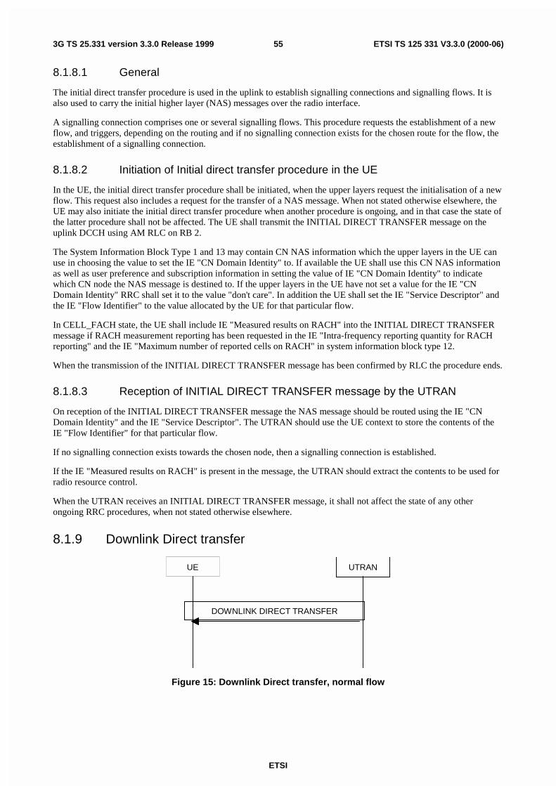
ETSI
3G TS 25.331 version 3.3.0 Release 1999 55 ETSI TS 125 331 V3.3.0 (2000-06)
8.1.8.1 General
The initial direct transfer procedure is used in the uplink to establish signalling connections and signalling flows. It isalso used to carry the initial higher layer (NAS) messages over the radio interface.
A signalling connection comprises one or several signalling flows. This procedure requests the establishment of a newflow, and triggers, depending on the routing and if no signalling connection exists for the chosen route for the flow, theestablishment of a signalling connection.
8.1.8.2 Initiation of Initial direct transfer procedure in the UE
In the UE, the initial direct transfer procedure shall be initiated, when the upper layers request the initialisation of a newflow. This request also includes a request for the transfer of a NAS message. When not stated otherwise elsewhere, theUE may also initiate the initial direct transfer procedure when another procedure is ongoing, and in that case the state ofthe latter procedure shall not be affected. The UE shall transmit the INITIAL DIRECT TRANSFER message on theuplink DCCH using AM RLC on RB 2.
The System Information Block Type 1 and 13 may contain CN NAS information which the upper layers in the UE canuse in choosing the value to set the IE "CN Domain Identity" to. If available the UE shall use this CN NAS informationas well as user preference and subscription information in setting the value of IE "CN Domain Identity" to indicatewhich CN node the NAS message is destined to. If the upper layers in the UE have not set a value for the IE "CNDomain Identity" RRC shall set it to the value "don't care". In addition the UE shall set the IE "Service Descriptor" andthe IE "Flow Identifier" to the value allocated by the UE for that particular flow.
In CELL_FACH state, the UE shall include IE "Measured results on RACH" into the INITIAL DIRECT TRANSFERmessage if RACH measurement reporting has been requested in the IE "Intra-frequency reporting quantity for RACHreporting" and the IE "Maximum number of reported cells on RACH" in system information block type 12.
When the transmission of the INITIAL DIRECT TRANSFER message has been confirmed by RLC the procedure ends.
8.1.8.3 Reception of INITIAL DIRECT TRANSFER message by the UTRAN
On reception of the INITIAL DIRECT TRANSFER message the NAS message should be routed using the IE "CNDomain Identity" and the IE "Service Descriptor". The UTRAN should use the UE context to store the contents of theIE "Flow Identifier" for that particular flow.
If no signalling connection exists towards the chosen node, then a signalling connection is established.
If the IE "Measured results on RACH" is present in the message, the UTRAN should extract the contents to be used forradio resource control.
When the UTRAN receives an INITIAL DIRECT TRANSFER message, it shall not affect the state of any otherongoing RRC procedures, when not stated otherwise elsewhere.
8.1.9 Downlink Direct transfer
UE UTRAN
DOWNLINK DIRECT TRANSFER
Figure 15: Downlink Direct transfer, normal flow

ETSI
3G TS 25.331 version 3.3.0 Release 1999 56 ETSI TS 125 331 V3.3.0 (2000-06)
8.1.9.1 General
The downlink direct transfer procedure is used in the downlink direction to carry higher layer (NAS) messages over theradio interface.
8.1.9.2 Initiation of downlink direct transfer procedure in the UTRAN
In the UTRAN, the direct transfer procedure is initiated when the upper layers request the transfer of a NAS messageafter the initial signalling connection is established. The UTRAN may also initiate the downlink direct transferprocedure when another RRC procedure is ongoing, and in that case the state of the latter procedure shall not beaffected. The UTRAN shall transmit the DOWNLINK DIRECT TRANSFER message on the downlink DCCH usingAM RLC on RB 3 or RB 4. The UTRAN should select the RB according to the following:
- If the non-access stratum indicates "low priority" for this message, RB 4 should be selected, if available.Specifically, for a GSM-MAP based CN, RB 4 should, if available, be selected when "SAPI 3" is requested. RB3 should be selected when RB 4 is not available.
- If the non-access stratum indicates "high priority" for this message, RB 3 should be selected. Specifically, for aGSM-MAP based CN, RB 3 should be selected when "SAPI 0" is requested.
The UTRAN sets the IE "CN Domain Identity" to indicate, which CN domain the NAS message is originated from.
8.1.9.3 Reception of a DOWNLINK DIRECT TRANSFER message by the UE
Upon reception of the DOWNLINK DIRECT TRANSFER message, the UE RRC shall, using the IE "CN DomainIdentity", route the contents of the higher layer PDU and the value of the IE"CN Domain Identity" to the correct higherlayer entity.
When the UE receives a DOWNLINK DIRECT TRANSFER message, it shall not affect the state of any other ongoingRRC procedures when not stated otherwise elsewhere.
8.1.9.4 Invalid DOWNLINK DIRECT TRANSFER message
If the UE receives a DOWNLINK DIRECT TRANSFER message, which contains a protocol error causing the variablePROTOCOL_ERROR_REJECT to be set to TRUE according to clause 16, the UE shall perform procedure specificerror handling as follows:
- Transmit an RRC STATUS message on the uplink DCCH using AM RLC and include the IE "Protocol errorinformation" with contents set to the value of the variable PROTOCOL_ERROR_INFORMATION.
When the transmission of the RRC STATUS message has been confirmed by RLC, the UE shall resume normaloperation as if the invalid DOWNLINK DIRECT TRANSFER message has not been received.

ETSI
ETSI TS 125 331 V3.3.0 (2000-06)573G TS 25.331 version 3.3.0 Release 1999
8.1.10 Uplink Direct transfer
UE UTRAN
UPLINK DIRECT TRANSFER
Figure 16: Uplink Direct transfer, normal flow
8.1.10.1 General
The uplink direct transfer procedure is used in the uplink direction to carry all subsequent higher layer (NAS) messagesover the radio interface.
8.1.10.2 Initiation of uplink direct transfer procedure in the UE
In the UE, the uplink direct transfer procedure shall be initiated when the upper layers request a transfer of a NASmessage after the initial signalling connection is established and upper layer indication is provided indicating that theNAS message belongs to an on-going signalling flow. When not stated otherwise elsewhere, the UE may also initiatethe uplink direct transfer procedure when another procedure is ongoing, and in that case the state of the latter procedureshall not be affected. The UE shall transmit the UPLINK DIRECT TRANSFER message on the uplink DCCH usingAM RLC on RB 3 or RB 4. The UE shall select the RB according to the following:
- If the non-access stratum indicates "low priority" for this message, RB 4 shall be selected, if available.Specifically, for a GSM-MAP based CN, RB 4 shall, if available, be selected when "SAPI 3" is requested. RB 3shall be selected when RB 4 is not available.
- If the non-access stratum indicates "high priority" for this message, RB 3 shall be selected. Specifically, for aGSM-MAP based CN, RB 3 shall be selected when "SAPI 0" is requested.
The UE shall set the IE "Flow Identifier" to the same value as that allocated to that particular flow when transmittingthe INITIAL DIRECT TRANSFER message for that flow.
8.1.10.3 Reception of UPLINK DIRECT TRANSFER message by the UTRAN
On reception of the UPLINK DIRECT TRANSFER message the NAS message should be routed using the valueindicated in the IE "Flow Identifier".
If the IE "Measured results on RACH" is present in the message, the UTRAN should extract the contents to be used forradio resource control.
When the UTRAN receives an UPLINK DIRECT TRANSFER message, it shall not affect the state of any otherongoing RRC procedures, when not stated otherwise elsewhere.
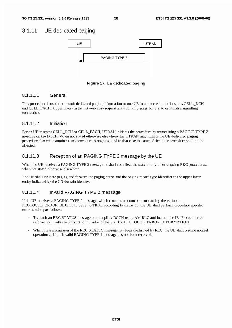
ETSI
ETSI TS 125 331 V3.3.0 (2000-06)583G TS 25.331 version 3.3.0 Release 1999
8.1.11 UE dedicated paging
UE UTRAN
PAGING TYPE 2
Figure 17: UE dedicated paging
8.1.11.1 General
This procedure is used to transmit dedicated paging information to one UE in connected mode in states CELL_DCHand CELL_FACH. Upper layers in the network may request initiation of paging, for e.g. to establish a signallingconnection.
8.1.11.2 Initiation
For an UE in states CELL_DCH or CELL_FACH, UTRAN initiates the procedure by transmitting a PAGING TYPE 2message on the DCCH. When not stated otherwise elsewhere, the UTRAN may initiate the UE dedicated pagingprocedure also when another RRC procedure is ongoing, and in that case the state of the latter procedure shall not beaffected.
8.1.11.3 Reception of an PAGING TYPE 2 message by the UE
When the UE receives a PAGING TYPE 2 message, it shall not affect the state of any other ongoing RRC procedures,when not stated otherwise elsewhere.
The UE shall indicate paging and forward the paging cause and the paging record type identifier to the upper layerentity indicated by the CN domain identity.
8.1.11.4 Invalid PAGING TYPE 2 message
If the UE receives a PAGING TYPE 2 message, which contains a protocol error causing the variablePROTOCOL_ERROR_REJECT to be set to TRUE according to clause 16, the UE shall perform procedure specificerror handling as follows:
- Transmit an RRC STATUS message on the uplink DCCH using AM RLC and include the IE "Protocol errorinformation" with contents set to the value of the variable PROTOCOL_ERROR_INFORMATION.
- When the transmission of the RRC STATUS message has been confirmed by RLC, the UE shall resume normaloperation as if the invalid PAGING TYPE 2 message has not been received.

ETSI
ETSI TS 125 331 V3.3.0 (2000-06)593G TS 25.331 version 3.3.0 Release 1999
8.1.12 Security mode control
UEUTRAN
SECURITY MODE COMMAND
SECURITY MODE COMPLETE
Figure 18: Security mode control procedure
8.1.12.1 General
The purpose of this procedure is to trigger the start of ciphering or to command the change of the cipher key, both forthe signalling link and for any of the radio bearers.
It is also used to start integrity protection or to restart integrity protection for uplink and downlink signalling.
8.1.12.2 Initiation
Prior to UTRAN initiates a security mode control procedure for control of ciphering and if the UE has radio bearersusing RLC-AM or RLC-UM, UTRAN should suspend all radio bearers belonging to the CN domain for which thesecurity mode control procedure is initiated. Also the signalling radio bearers are suspended. For each suspended radiobearer, UTRAN includes the current RLC send sequence number in the IE "Radio bearer downlink activation time info"in the IE "Ciphering mode info".
Further, if the UE has radio bearers using RLC-TM, UTRAN sets the IE "Activation time for DPCH" in the IE"Ciphering mode info" to the CFN at which the new ciphering configuration shall become active.
To start or reconfigure ciphering and/or integrity protection, the UTRAN sends a SECURITY MODE COMMANDmessage on the downlink DCCH in AM RLC using the present ciphering and/or integrity protection configuration.
When the transmission of the SECURITY MODE COMMAND has been confirmed by RLC, and if the security modecontrol procedure is used to control ciphering, UTRAN should resume all the suspended radio bearers using RLC-AMor RLC-UM, that use the old ciphering configuration for the transmission of RLC PDUs with RLC sequence numberless than the RLC sequence number indicated in the IE "Radio bearer downlink ciphering activation time info" sent tothe UE, and the new ciphering configuration for the transmission of RLC PDUs with RLC sequence number greaterthan or equal to the RLC sequence number indicated in the IE "Radio bearer downlink ciphering activation time info"sent to the UE.
8.1.12.3 Reception of SECURITY MODE COMMAND message by the UE
Upon reception of the SECURITY MODE COMMAND message, the UE shall perform the actions for the receivedinformation elements according to 8.5.7.

ETSI
ETSI TS 125 331 V3.3.0 (2000-06)603G TS 25.331 version 3.3.0 Release 1999
If the IE "security capabilities" is the same as indicated by variable UE_CAPABILITY_TRANSFERRED, the UE shallsuspend (from sequence numbers on, which are greater than or equal to each radio bearer's downlink cipheringactivation time) all radio bearers using RLC-AM or RLC-UM that belong to the CN domain indicated in the IE "CNdomain identity", received in the message SECURITY MODE COMMAND. The UE shall also suspend all thesignalling radio bearers. When the radio bearers have been suspended, the UE shall send a SECURITY MODECOMPLETE message on the uplink DCCH in AM RLC, using the old ciphering and/or the new integrity protectionconfiguration.
If a new integrity protection key has been received, the new key shall be used and the integrity protection "downlinkHFN" shall be set to 0 at the RRC sequence indicated in IE "Downlink integrity protection activation info" included inthe IE "Integrity protection mode info". In the uplink the UE shall start using the new key and set "uplink HFN" to 0 atat the RRC sequence indicated in IE "Uplink integrity protection activation info" included in the IE "Integrity protectionmode info".
If the variable RB_UPLINK_CIPHERING_ACTIVATION_TIME_INFO is set, the UE shall include and set the IE"Radio bearer uplink ciphering activation time info" to the value of that variable.
If a new ciphering key is available, the new ciphering key shall be used and the uplink and downlink cipheringhyperframe number shall be set to zero for the signalling radio bearers and the radio bearers used by the CN indicated inthe IE "CN domain identity".
When the transmission of the SECURITY MODE COMPLETE message has been confirmed by RLC, the UE shallresume data transmission on any suspended radio bearers mapped on RLC-UM or RLC-AM, clear the variableRB_UPLINK_CIPHERING_ACTIVATION_TIME_INFO and the procedure ends.
8.1.12.4 Cipher activation time too short
If the time specified by the IE "Activation time for DPCH" or the IE "Radio bearer downlink ciphering activation timeinfo" contained in the IE "Ciphering mode info" has elapsed, the UE shall switch immediately to the new cipherconfiguration.
8.1.12.5 Unsuccessful verification of IE 'UE ciphering capabilities'
If the received IE 'UE ciphering capabilities' is not the same as indicated by variableUE_CAPABILITY_TRANSFERRED, the UE shall release all its radio resources, enter idle mode and the procedureends on the UE side. Actions the UE shall perform when entering idle mode are given in subclause 8.5.2.
8.1.12.6 Reception of SECURITY MODE COMPLETE message by the UTRAN
UTRAN should apply integrity protection on the received SECURITY MODE COMPLETE message and allsubsequent messages. When UTRAN has received a SECURITY MODE COMPLETE message and the integrityprotection has successfully been applied, UTRAN shall use
for radio bearers using RLC-AM or RLC-UM:
- the old ciphering configuration for received RLC PDUs with RLC sequence number less than the RLC sequencenumber indicated in the IE "Radio bearer uplink ciphering activation time info" sent by the UE.
- the new ciphering configuration for received RLC PDUs with RLC sequence number greater than or equal to theRLC sequence number indicated in the IE "Radio bearer uplink ciphering activation time info" sent by the UE.
for radio bearers using RLC-TM:
- the new ciphering configuration for the received RLC PDUs at the CFN as indicated in the IE "Activation timefor DPCH" in the IE "Ciphering mode info".
and the procedure ends.
8.1.12.7 Invalid SECURITY MODE COMMAND message
If the SECURITY MODE COMMAND message contains a protocol error causing the variablePROTOCOL_ERROR_REJECT to be set to TRUE according to clause 16, the UE shall perform procedure specificerror handling as follows:

ETSI
ETSI TS 125 331 V3.3.0 (2000-06)613G TS 25.331 version 3.3.0 Release 1999
- Transmit a SECURITY MODE FAILURE message on the uplink DCCH using AM RLCand set the IE "failurecause" the cause value "protocol error".
- Include the IE "Protocol error information" with contents set to the value of the variablePROTOCOL_ERROR_INFORMATION.
- When the transmission of the SECURITY MODE FAILURE message has been confirmed by RLC, the UE shallresume normal operation as if the invalid SECURITY MODE COMMAND message has not been received andthe procedure ends.
8.1.13 Signalling connection release procedure
UE UTRAN
SIGNALLING CONNECTIONRELEASE
Figure 19: Signalling connection release procedure, normal case
8.1.13.1 General
The signalling connection release procedure is used to notify to the UE that one of its ongoing signalling connections toa CN domain has been released. The procedure does not initiate the release of the RRC connection.
8.1.13.2 Initiation of SIGNALLING CONNECTION RELEASE by the UTRAN
The UTRAN may initiate the signalling connection release procedure, if it receives a signalling connection releaserequest from one CN domain and if the UE remains engaged in a signalling connection to another CN domain.
To initiate the procedure, the UTRAN transmits a SIGNALLING CONNECTION RELEASE message on DCCH usingAM RLC.
The IE "Flow Identifier" indicates the signalling flow identities that are released when the CN domain releases thesignalling connection to the UE.
8.1.13.3 Reception of SIGNALLING CONNECTION RELEASE by the UE
Upon reception of a SIGNALLING CONNECTION RELEASE message, the UE shall indicate the release of allsignalling flows identified by the values of the IE "Flow identifier" to the corresponding higher layer entities.
8.1.13.4 Invalid SIGNALLING CONNECTION RELEASE message
If the UE receives a SIGNALLING CONNECTION RELEASE message, which contains a protocol error causing thevariable PROTOCOL_ERROR_REJECT to be set to TRUE according to clause 16, the UE shall perform procedurespecific error handling as follows:
- Transmit an RRC STATUS message on the uplink DCCH using AM RLC and include the IE "Protocol errorinformation" with contents set to the value of the variable PROTOCOL_ERROR_INFORMATION.
- When the transmission of the RRC STATUS message has been confirmed by RLC, the UE shall resume normaloperation as if the invalid SIGNALLING CONNECTION RELEASE message has not been received.

ETSI
ETSI TS 125 331 V3.3.0 (2000-06)623G TS 25.331 version 3.3.0 Release 1999
8.1.14 Signalling connection release request procedure
UE UTRAN
SIGNALLING CONNECTIONRELEASE REQUEST
Figure 20: Signalling connection release request procedure, normal case
8.1.14.1 General
The signalling connection release request procedure is used by the UE to request from the UTRAN that one or more ofits flow identifiers should be released. The procedure may initiate the signalling connection release or RRC connectionrelease procedure.
8.1.14.2 Initiation
The UE shall initiate the signalling connection release procedure, if it receives a request from the higher layers torelease one or more signalling sessions.
To initiate the procedure, the UE transmits a SIGNALLING CONNECTION RELEASE REQUEST message on DCCHusing AM RLC. When the transmission of SIGNALLING CONNECTION RELEASE REQUEST message has beenconfirmed by RLC, the UE shall delete the released flow identifier(s).
The IE "Flow Identifier" indicates the signalling flow identities which are requested to be released in the UTRAN.
8.1.14.3 Reception of SIGNALLING CONNECTION RELEASE REQUEST by theUTRAN
Upon reception of a SIGNALLING CONNECTION RELEASE REQUEST message, the UTRAN may initiate the RRCconnection release procedure, if the UE has requested the release of all its remaining signalling connections. If allremaining signalling connections are not requested to be released, the UTRAN may initiate the signalling connectionrelease procedure.
8.1.15 Counter check
UE UTRAN
COUNTER CHECK
COUNTER CHECK RESPONSE
Figure 21: Counter check procedure
8.1.15.1 General
The counter check procedure is used by the UTRAN to perform a local authentication. The purpose of the procedure isto check that the amount of data sent in both directions (uplink/downlink) during the RRC connection is the same at theUTRAN and at the UE (to prevent a possible intruder – a 'man-in-the-middle' – to operate). It should be noted that this

ETSI
ETSI TS 125 331 V3.3.0 (2000-06)633G TS 25.331 version 3.3.0 Release 1999
requires that the COUNT-C values for each radio bearer are maintained even if ciphering is not used. This procedure isonly applicable to radio bearers using UM or AM mode of RLC. Applying this procedure for radio bearers usingtransparent mode RLC is FFS.
8.1.15.2 Initiation
The UTRAN is monitoring the COUNT-C value associated to each radio bearer using UM or AM RLC. The procedureis triggered whenever any of these values reaches a critical checking value. The granularity of these checking valuesand the values themselves are defined to the UTRAN by the visited network. The UTRAN initiates the procedure bysending a COUNTER CHECK message on the downlink DCCH.
8.1.15.3 Timer expiry at UTRAN
If a timer started at UTRAN when sending the COUNTER CHECK message expires before a response from the UE isreceived, the UTRAN should release the RRC connection.
8.1.15.4 Reception of a COUNTER CHECK message by the UE
When the UE receives a COUNTER CHECK message it shall compare the COUNT-C MSB values received in theCOUNTER CHECK message to the COUNT-C MSB values of the corresponding radio bearers.
If the number of radio bearers using UM or AM RLC mode or any of the COUNT-C MSB values is different themismatching COUNT-C values shall be included in a COUNTER CHECK RESPONSE message.
The UE shall send the COUNTER CHECK RESPONSE message on the uplink DCCH.
8.1.15.5 Reception of the COUNTER CHECK RESPONSE message by UTRAN
If the UTRAN receives a COUNTER CHECK RESPONSE message that does not contain any COUNT-C values, theprocedure ends.
If the UTRAN receives a COUNTER CHECK RESPONSE message that contains one or several COUNT-C values, itshould compare the COUNT-C values in the message to the COUNT-C values which were used in forming theCOUNTER CHECK message.
If there is no difference or if the difference is acceptable, the procedure ends. The limits for an acceptable difference aredefined to the UTRAN by the visited network.
If there is a difference that is not acceptable, UTRAN should initiate the release of the RRC connection.
8.1.15.6 Invalid COUNTER CHECK message
If the UE receives a COUNTER CHECK message which contains a protocol error causing the variablePROTOCOL_ERROR_REJECT to be set to TRUE according to clause 16, the UE shall perform procedure specificerror handling as follows:
- Transmit an RRC STATUS message on the uplink DCCH using AM RLC and include the IE "Protocol errorinformation" with contents set to the value of the variable PROTOCOL_ERROR_INFORMATION.
- When the transmission of the RRC STATUS message has been confirmed by RLC, the UE shall resume normaloperation as if the invalid COUNTER CHECK message has not been received.

ETSI
ETSI TS 125 331 V3.3.0 (2000-06)643G TS 25.331 version 3.3.0 Release 1999
8.2 Radio Bearer control procedures
8.2.1 Radio bearer establishment
UE UTRAN
RADIO BEARER SETUP
RADIO BEARER SETUP COMPLETE
Figure 22: Radio Bearer Establishment, normal case
UE UTRAN
RADIO BEARER SETUP
RADIO BEARER SETUP FAILURE
Figure 23: Radio Bearer Establishment, UE reverts to old configuration
8.2.1.1 General
The purpose with this procedure is to establish new radio bearer(s). Each radio bearer established by the procedurebelongs to one of the following categories:
a signalling radio bearer, i.e. used for control plane signalling;
a radio bearer that implements a radio access bearer (RAB) or RAB subflow(s) in the user plane.
While establishing radio bearers, the procedure may perform a hard handover, see 8.3.5. The procedure may also beused to establish a transport channel for the transparent transfer of signalling.
8.2.1.2 Initiation
The upper layer in the network may request an establishment of radio bearer(s).
To initiate the procedure, UTRAN should:
- configure new radio links in any new physical channel configuration and start transmission and reception on thenew radio links;
- transmit a RADIO BEARER SETUP message on the downlink DCCH using AM or UM RLC.
If the Radio Bearer Establishment procedure is simultaneous with SRNS relocation procedure, and ciphering and/orintegrity protection are activated, transmit new ciphering and/or integrity protection information to be used afterreconfiguration.
If transport channels are added, reconfigured or deleted in uplink and/or downlink, UTRAN shall:
- set TFCS according to the new transport channel(s).

ETSI
ETSI TS 125 331 V3.3.0 (2000-06)653G TS 25.331 version 3.3.0 Release 1999
If the IE "Activation Time" is included, UTRAN should set it to a value taking the UE performance requirements intoaccount.
UTRAN should take the UE capabilities into account when setting the new configuration.
8.2.1.3 Reception of a RADIO BEARER SETUP message by the UE
Upon reception of a RADIO BEARER SETUP message the UE shall perform actions as specified below and transmit aRADIO BEARER SETUP COMPLETE message on the uplink DCCH using AM RLC.
If the variable RB_UPLINK_CIPHERING_ACTIVATION_TIME_INFO is set, the UE shall include and set the IE"Radio bearer uplink ciphering activation time info" to the value of that variable.
When the transmission of the RADIO BEARER SETUP COMPLETE message has been confirmed by RLC the UEshall resume data transmission on RB 3 and upwards if RLC-AM or RLC-UM is used on those radio bearers, the UEshall clear the variable ORDERED_CONFIG, clear the variableRB_UPLINK_CIPHERING_ACTIVATION_TIME_INFO and the procedure ends.
The UE shall store the received UE Information Elements, RB Information Elements, TrCH Information Elements andPhyCH information elements in the variable ORDERED_CONFIG.
The UE shall act upon all received information elements as specified in 8.5.7, unless specified otherwise in thefollowing.
The UE shall be able to receive an RADIO BEARER SETUP message and perform a hard handover, even if no priorUE measurements have been performed on the target cell and/or frequency:
The UE shall:
- for the new radio bearer(s), use the multiplexing option applicable for the transport channels used according tothe IE "RB mapping info";
- for the new radio bearer(s), if the variable CIPHERING_STATUS is set to "Started", initialise ciphering on thoseradio bearers using the current hyperframe number. For non-transparent mode radio bearers this hyperframenumber is the highest used HFN (during the lifetime of the current cipher/integrity key set) incremented by one.All transparent mode radio bearers have a common hyperframe number (in the MAC layer), which is notincremented due to addition of new transparent radio bearer(s);
- in case of non-transparent mode radio bearers transmit the current hyperframe number to UTRAN in RADIOBEARER SETUP COMPLETE message;
- for radio bearer(s) existing prior to the message, use the multiplexing option applicable for the transport channelsused, according to their IE "RB mapping info" or their previously stored multiplexing options;
- configure MAC multiplexing if that is needed in order to use said transport channel(s);
- use MAC logical channel priority when selecting TFC in MAC;
- suspend data transmission on RB 3 and upward, if RLC-AM or RLC-UM is used on those radio bearers.
If the IE "New C-RNTI" is included, the UE shall:
- use that C-RNTI when using common transport channels of type RACH, FACH and CPCH in the current cell.
If the IE "RAB information to setup" is included, the procedure is used to establish radio bearers belonging to a radioaccess bearer and the UE shall:
- Associate the new radio bearers with the radio access bearer that is identified by the IE "RAB info".
- Check whether that radio acces bearer exists in the variable ESTABLISHED_RABS.
If the radio access bearer exists the UE shall:
- store information about the radio bearer under the radio access bearer entry in the variableESTABLISHED_RABS.

ETSI
ETSI TS 125 331 V3.3.0 (2000-06)663G TS 25.331 version 3.3.0 Release 1999
If the radio access bearer does not exist the UE shall:
- store information about the new radio access bearer in the variable ESTABLISHED_RABS
- store information about the radio bearer under the radio access bearer entry in the variableESTABLISHED_RABS.
- indicate the establishment of the radio access bearer to the upper layer entity using the IE "CN domainidentity", forwarding the content of the IE "RAB identity".
- For each new radio bearer, the UE shall:
- create a new RAB subflow for the radio access bearer.
- Number the RAB subflow in the order of when the radio bearers within the radio access bearers wherecreated.
- Store the number of the RAB subflow in the variable ESTABLISHED_RABS.
- Indicate the establishment of each new RAB subflow to the upper layer entity using the IE "CN domainidentity".
The UE should turn off the transmitter during the reconfiguration. The UE may first release the current physical channelconfiguration and shall then establish a new physical channel configuration according to 8.5.7 and the following.
If neither the IE "PRACH info" nor the IE "Uplink DPCH info" is included, the UE shall
- Let the physical channel of type PRACH that is given in system information be the default in uplink.
If neither the IE "Secondary CCPCH info" nor the IE "Downlink DPCH info" is included, the UE shall
- Start to receive the physical channel of type Secondary CCPCH that is given in system information.
In FDD, if the IE 'PDSCH code mapping' is included but the IE 'PDSCH with SHO DCH Info' is not included and if theDCH has only one link in its active set then the UE shall act upon the 'PDSCH code mapping' IE as specified insubclause 8.5.7 and:
- Infer that the PDSCH will be transmitted from the BS from which the downlink DPCH is transmitted.
The UE shall use the transport channel(s) applicable for the physical channel types that is used. If neither the IE "TFS"is included or previously stored in the UE for that transport channel(s), the UE shall:
- Use the TFS given in system information.
If none of the TFS stored is compatible with the physical channel, the UE shall:
- Delete stored TFS and use the TFS given in system information:
The UE shall enter a state according to 8.5.8.
8.2.1.4 Unsupported or unacceptable configuration in the UE
If UTRAN instructs the UE to use a configuration, which it does not support or if the variableUNACCEPTABLE_CONFIGURATION is set to TRUE, the UE transmit a RADIO BEARER SETUP FAILUREmessage on the DCCH using AM RLC and set the IE "failure cause" the cause value "configuration unacceptable". Ifthe radio bearer setup procedure affects several radio bearers, the UE may include the identities of the radio bearers forwhich the procedure would have been succesful into the RADIO BEARER SETUP FAILURE message.
When the transmission of the RADIO BEARER SETUP FAILURE message has been confirmed by RLC, the UE shallresume data transmission on RB 3 and upwards if RLC-AM or RLC-UM is used on those radio bearers, the UE shallclear the variable ORDERED_CONFIG and the procedure ends.
8.2.1.5 Physical channel failure
If the UE failed to establish the physical channel(s) indicated in the RADIO BEARER SETUP message the UE shall:

ETSI
ETSI TS 125 331 V3.3.0 (2000-06)673G TS 25.331 version 3.3.0 Release 1999
- Revert to the configuration prior to the reception of the RADIO BEARER SETUP message (old configuration)and transmit a RADIO BEARER SETUP FAILURE message on the DCCH using AM RLC. The procedure endsand the UE shall resume data transmission on RB 3 and upwards if RLC-AM or RLC-UM is used on those radiobearers and resumes the normal operation as if no radio bearer establishment attempt had occurred.
If the radio bearer setup procedure affects several radio bearers, the UE may include the identities of the radio bearersfor which the procedure would have been succesful into the RADIO BEARER SETUP FAILURE message.
A physical channel failure occurs in case the criteria as defined in 8.5.4 are not fulfilled. If the UE is unable to revert tothe old configuration or if used, the activation time has expired, the UE shall:
- initiate a RRC connection re-establishment procedure according to subclause 8.1.5 and set the IE "failure cause"the cause value "physical channel failure".
8.2.1.6 Reception of the RADIO BEARER SETUP COMPLETE message by theUTRAN
When UTRAN has received the RADIO BEARER SETUP COMPLETE message, UTRAN may delete any oldconfiguration and the procedure ends on the UTRAN side.
If the IE "UL Timing Advance" is included, UTRAN shall evaluate the timing advance value that the UE has to use inthe new cell after handover.
8.2.1.7 Reception of RADIO BEARER SETUP FAILURE by the UTRAN
When UTRAN has received the RADIO BEARER SETUP FAILURE message, UTRAN may restore the old and deletethe new configuration and the procedure ends on the UTRAN side. Upper layers should be notified of the failure.
8.2.1.8 Subsequently received RADIO BEARER SETUP messages
If the variable ORDERED_CONFIG is set because of a RADIO BEARER SETUP message previously received, theUE shall
- ignore the subsequently received RADIO BEARER SETUP message
- keep the configuration as before the subsequent RADIO BEARER SETUP message was received.
8.2.1.9 Incompatible simultaneous reconfiguration
If the variable ORDERED_CONFIG is set (because of any message other than RADIO BEARER SETUP) upon thereception of the RADIO BEARER SETUP message, the UE shall:
- keep the old configuration as before the RADIO BEARER SETUP message was received;
- transmit a RADIO BEARER SETUP FAILURE message on the DCCH using AM RLC. The UE shall set the IE"failure cause" to "incompatible simultaneous reconfiguration". When the transmission of RADIO BEARERSETUP FAILURE message has been confirmed by RLC the procedure ends.
8.2.1.10 Invalid RADIO BEARER SETUP message
If the variable ORDERED_CONFIG is not set and the RADIO BEARER SETUP message contains a protocol errorcausing the variable PROTOCOL_ERROR_REJECT to be set to TRUE according to clause 16, the UE shall performprocedure specific error handling as follows:
- transmit a RADIO BEARER SETUP FAILURE message on the uplink DCCH using AM RLCand set the IE"failure cause" the cause value "protocol error";
- include the IE "Protocol error information" with contents set to the value of the variablePROTOCOL_ERROR_INFORMATION;
- when the transmission of the RADIO BEARER SETUP FAILURE message has been confirmed by RLC, the UEshall resume data transmission on RB 3 and upwards if RLC-AM or RLC-UM is used on those radio bearers.

ETSI
ETSI TS 125 331 V3.3.0 (2000-06)683G TS 25.331 version 3.3.0 Release 1999
The UE shall resume normal operation as if the invalid RADIO BEARER SETUP message has not beenreceived and the procedure ends.
8.2.2 Radio bearer reconfiguration
UE UTRAN
RADIO BEARER RECONFIGURATION
RADIO BEARERRECONFIGURATION COMPLETE
Figure 24: Radio bearer reconfiguration, normal flow
UE UTRAN
RADIO BEARER RECONFIGURATION
RADIO BEARERRECONFIGURATION FAILURE
Figure 25: Radio bearer reconfiguration, failure case
8.2.2.1 General
The radio bearer reconfiguration procedure is used to reconfigure parameters for a radio bearer or the signalling link toreflect a change in QoS. While doing so, the procedure may perform a hard handover, see 8.3.5.
8.2.2.2 Initiation
To initiate the procedure, UTRAN should:
- configure new radio links in any new physical channel configuration and start transmission and reception on thenew radio links;
- transmit a RADIO BEARER RECONFIGURATION message on the downlink DCCH using AM or UM RLC.
If the Radio Bearer Reconfiguration procedure is simultaneous with SRNS relocation procedure, and ciphering and/orintegrity protection are activated, transmit new ciphering and/or integrity protection information to be used afterreconfiguration.
If transport channels are added, reconfigured or deleted in uplink and/or downlink, the UTRAN should:
- Set TFCS according to the new transport channel(s).
If transport channels are added or deleted in uplink and/or downlink, the UTRAN should:
- Send the RB Mapping Info for the new configuration
UTRAN should indicate that uplink transmission shall be suspended on certain bearers. Uplink transmission on a radiobearer used by the RRC signalling should not be suspended.
If the IE "Activation Time" is included, UTRAN should set it to a value taking the UE performance requirements intoaccount.

ETSI
ETSI TS 125 331 V3.3.0 (2000-06)693G TS 25.331 version 3.3.0 Release 1999
UTRAN should take the UE capabilities into account when setting the new configuration.
If the message is used to initiate a transition from CELL_DCH to CELL_FACH state, the UTRAN may assign acommon channel configuration of a given cell and C-RNTI to be used in that cell to the UE.
8.2.2.3 Reception of RADIO BEARER RECONFIGURATION by the UE inCELL_DCH state
Upon reception of a RADIO BEARER RECONFIGURATION message in CELL_DCH state, the UE shall performactions specified below.
The UE shall be able to receive an RADIO BEARER RECONFIGURATION message and perform a hard handover,even if no prior UE measurements have been performed on the target cell and/or frequency.
The UE shall store the received UE Information Elements, RB Information Elements, TrCH Information Elements andPhyCH information elements in the variable ORDERED_CONFIG.
The UE shall act upon all received information elements as specified in 8.5.7, unless specified otherwise in thefollowing.
The UE shall:
- For each reconfigured radio bearer or signalling link, use the multiplexing option applicable for the transportchannels used according to the IE "RB mapping info";
- Configure MAC multiplexing if that is needed in order to use said transport channel(s);
- Use MAC logical channel priority when selecting TFC in MAC;
- Suspend or resume uplink transmission for each radio bearer, as indicated by the IE "RB suspend/resume"information element;
- Suspend data transmission on RB 3 and upward, if RLC-AM or RLC-UM is used on those radio bearers.
The UE should turn off the transmitter during the reconfiguration. The UE may first release the current physical channelconfiguration and shall then establish a new physical channel configuration according to 8.5.7 and the following.
If neither the IE "PRACH info" nor the IE "Uplink DPCH info" is included, the UE shall:
- Let the physical channel of type PRACH that is given in system information be the default in.
If neither the IEs "Secondary CCPCH info" nor "Downlink DPCH info" is included, the UE shall:
- Start to receive the physical channel of type Secondary CCPCH that is given in system information.
In FDD, if the IE 'PDSCH code mapping' is included but the IE 'PDSCH with SHO DCH Info' is not included and if theDCH has only one link in its active set then the UE shall act upon the 'PDSCH code mapping' IE as specified insubclause 8.5.7 and:
- Infer that the PDSCH will be transmitted from the BS from which the downlink DPCH is transmitted.
The UE shall use the transport channel(s) applicable for the physical channel types that is used. If neither the IE "TFS"is included or previously stored in the UE for that transport channel(s), the UE shall:
- Use the TFS given in system information.
If none of the TFS stored is compatible with the physical channel, the UE shall;
- Delete stored TFS and use the TFS given in system information.
If the IE "Primary CCPCH info" in TDD or "Primary CPICH info" in FDD and the IE "New C-RNTI" are included, theUE shall:
- Select the cell indicated by the IE "Primary CCPCH info" in TDD or "Primary CPICH info" in FDD;

ETSI
ETSI TS 125 331 V3.3.0 (2000-06)703G TS 25.331 version 3.3.0 Release 1999
- Use the given C-RNTI when using common transport channels of type RACH, FACH and CPCH in that givencell after having completed the transition to that cell.
The UE shall enter a state according to 8.5.8.
The UE shall transmit a RADIO BEARER RECONFIGURATION COMPLETE message on the uplink DCCH usingAM RLC.
If the variable RB_UPLINK_CIPHERING_ACTIVATION_TIME_INFO is set, the UE shall include and set the IE"Radio bearer uplink ciphering activation time info" to the value of that variable.
When the transmission of the RADIO BEARER RECONFIGURATION COMPLETE message has been confirmed byRLC, the UE shall clear the variable ORDERED_CONFIG, clear the variableRB_UPLINK_CIPHERING_ACTIVATION_TIME_INFO and the UE shall resume data transmission on each radiobearer fulfilling the following criteria:
- The radio bearer identity is RB 3 and upward;
- RLC-AM or RLC-UM is used; and
- The radio bearers was not indicated to be suspended by the IE "RB suspend/resume" information element in theRADIO BEARER RECONFIGURATION message.
The procedure ends.
If the RADIO BEARER RECONFIGURATION message is used to initiate a transition from CELL_DCH toCELL_FACH state, the RADIO BEARER RECONFIGURATION COMPLETE message shall be transmitted on theRACH after the UE has completed the state transition. The UE shall clear the variable ORDERED_CONFIG and theprocedure ends.
8.2.2.4 Reception of an RADIO BEARER RECONFIGURATION message by the UEin CELL_FACH state
Upon reception of a RADIO BEARER RECONFIGURATION message in CELL_FACH state, the UE shall performactions specified below.
The UE shall store the received UE Information Elements, RB Information Elements, TrCH Information Elements andPhyCH information elements in the variable ORDERED_CONFIG.
The UE shall act upon all received information elements as specified in 8.5.7, unless specified otherwise in thefollowing.
The UE shall:
- For each reconfigured radio bearer or signalling link, use the multiplexing option applicable for the transportchannels used according to the IE "RB mapping info";
- Configure MAC multiplexing if that is needed in order to use said transport channel(s);
- Use MAC logical channel priority when selecting TFC in MAC;
- Suspend or resume uplink transmission for each radio bearer, as indicated by the IE "RB suspend/resume".
If the IE "New C-RNTI" is included, the UE shall:
- Use that C-RNTI when using common transport channels of type RACH, FACH and CPCH in the current cell.
If neither the IE "PRACH info" nor the IE "Uplink DPCH info" is included, the UE shall:
- Let the physical channel of type PRACH that is given in system information be the default in uplink.
If neither the IE "Secondary CCPCH info" nor the IE "Downlink DPCH info" is included, the UE shall:
- Start to receive the physical channel of type Secondary CCPCH that is given in system information.

ETSI
ETSI TS 125 331 V3.3.0 (2000-06)713G TS 25.331 version 3.3.0 Release 1999
In FDD, if the IE 'PDSCH code mapping' is included but the IE 'PDSCH with SHO DCH Info' is not included then theUE shall act upon the 'PDSCH code mapping' IE as specified in Subclause 8.5.7 and:
- Infer that the PDSCH will be transmitted from the BS from which the downlink DPCH is transmitted (therebeing only one link in the active set).
The UE shall use the transport channel(s) applicable for the physical channel types that is used. If neither the IE "TFS"is included or previously stored in the UE for that transport channel(s), the UE shall:
- Use the TFS given in system information.
If none of the TFS stored is compatible with the physical channel, the UE shall:
- Delete stored TFS and use the TFS given in system information.
The UE shall enter a state according to 8.5.8.
The UE shall transmit a RADIO BEARER RECONFIGURATION COMPLETE message on the uplink DCCH usingAM RLC.
If the variable RB_UPLINK_CIPHERING_ACTIVATION_TIME_INFO is set, the UE shall include and set the IE"Radio bearer uplink ciphering activation time info" to the value of that variable.
When the transmission of the RADIO BEARER RECONFIGURATION COMPLETE message has been confirmed byRLC, the UE shall clear the variable ORDERED_CONFIG, clear the variableRB_UPLINK_CIPHERING_ACTIVATION_TIME_INFO and the procedure ends.
8.2.2.5 Reception of a RADIO BEARER RECONFIGURATION COMPLETEmessage by the UTRAN
When UTRAN has received the RADIO BEARER RECONFIGURATION COMPLETE message, UTRAN may deletethe old configuration..
If the IE "UL Timing Advance" is included, UTRAN shall evaluate the timing advance value that the UE has to use inthe new cell after handover.
8.2.2.6 Unsupported or unacceptable configuration in the UE
If the UTRAN instructs the UE to use a configuration, which it does not support or if the variableUNACCEPTABLE_CONFIGURATION is set to TRUE, the UE shall:
- transmit a RADIO BEARER RECONFIGURATION FAILURE message on the DCCH using AM RLC;
- set the cause value in IE "failure cause" to "configuration unacceptable";
- if the radio bearer reconfiguration procedure affects several radio bearers, the UE may include the identities ofthe radio bearers for which the procedure would have been succesful into the RADIO BEARERRECONFIGURATION FAILURE message.
When the transmission of the RADIO BEARER RECONFIGURATION FAILURE message has been confirmed byRLC, the UE shall clear the variable ORDERED_CONFIG and the UE shall resume data transmission on RB 3 andupwards if RLC-AM or RLC-UM is used on those radio bearers. It shall resume the normal operation as if no radiobearer reconfiguration attempt had occurred and the procedure ends.
8.2.2.7 Physical channel failure
A physical channel failure occurs in case the criteria as defined in 8.5.4 are not fulfilled.
If the UE failed to establish the physical channel(s) indicated in the RADIO BEARER RECONFIGURATION messagethe UE shall:
- revert to the configuration prior to the reception of the RADIO BEARER RECONFIGURATION message (oldconfiguration);

ETSI
ETSI TS 125 331 V3.3.0 (2000-06)723G TS 25.331 version 3.3.0 Release 1999
- transmit a RADIO BEARER RECONFIGURATION FAILURE message on the DCCH using AM RLC;
- set the cause value in IE "failure cause" to "physical channel failure";
- if the radio bearer reconfiguration procedure affects several radio bearers, the UE may include the identities ofthe radio bearers for which the procedure would have been succesful into the RADIO BEARERRECONFIGURATION FAILURE message;
- when the transmission of the RADIO BEARER RECONFIGURATION FAILURE message has been confirmedby RLC, the UE shall resume data transmission on RB 3 and upwards if RLC-AM or RLC-UM is used on thoseradio bearers. The procedure ends and the UE resumes the normal operation as if no radio bearer reconfigurationattempt had occurred.
If the UE is unable to revert to the old configuration or if used, the activation time has expired, the UE shall:
- Initiate a RRC connection re-establishment procedure according to subclause 8.1.5.
8.2.2.8 Reception of a RADIO BEARER RECONFIGURATION FAILURE messageby the UTRAN
When UTRAN has received the RADIO BEARER RECONFIGURATION FAILURE message, UTRAN may restorethe old and delete the new configuration. The procedure ends on the UTRAN side. Upper layers should be notified ofthe failure.
8.2.2.9 No response from the UE in CELL DCH_state
If no RADIO BEARER RECONFIGURATION COMPLETE message or RADIO BEARER RECONFIGURATIONFAILURE message has been received, the UTRAN may delete the old and new configuration. If the UE requests a re-establishment of the RRC connection, before all UE dedicated resources have been cleared, the new configuration maybe re-assigned in the re-establishment procedure.
During transition from CELL_DCH to CELL_FACH, the UTRAN may also receive a CELL UPDATE message if theUE cannot use the assigned physical channel.
8.2.2.10 No response from the UE in CELL_FACH state
If no RADIO BEARER RECONFIGURATION COMPLETE message or RADIO BEARER RECONFIGURATIONFAILURE message has been received, the UTRAN may delete the old and new configuration. If the UE makes a cellupdate before all UE dedicated resources have been cleared, the configuration procedure can be restarted.
8.2.2.11 Physical channel failure during transmission from CELL_DCH toCELL_FACH
If the UE fails to select the cell, which was assigned in the RADIO BEARER RECONFIGURATION messageinitiating transition from CELL_DCH to CELL_FACH, the UE shall perform cell reselection and initiate the cell updateprocedure.
8.2.2.12 Suspension of signalling bearer
If the RADIO BEARER RECONFIGURATION message includes a request to suspend the signalling link with the IE"RB suspend/resume", the UE shall:
- Revert to the configuration prior to the reception of the RADIO BEARER RECONFIGURATION message (oldconfiguration);
- send a RADIO BEARER RECONFIGURATION FAILURE message to the UTRAN;
- set the cause value in IE "failure cause" to "configuration unacceptable";
- When the transmission of the RADIO BEARER RECONFIGURATION FAILURE message has been confirmedby RLC, the procedure ends and the UE shall resume the normal operation as if no radio bearer reconfigurationattempt had occurred.

ETSI
ETSI TS 125 331 V3.3.0 (2000-06)733G TS 25.331 version 3.3.0 Release 1999
8.2.2.13 Subsequently received RADIO BEARER RECONFIGURATION messages
If the variable ORDERED_CONFIG is set because of a RADIO BEARER RECONFIGURATION message previouslyreceived, the UE shall
- ignore the subsequently received RADIO BEARER RECONFIGURATION message
- keep the configuration as before the subsequent RADIO BEARER RECONFIGURATION message wasreceived.
8.2.2.14 Incompatible simultaneous reconfiguration
If the variable ORDERED_CONFIG is set (because of any message other than RADIO BEARERRECONFIGURATION) upon the reception of the RADIO BEARER RECONFIGURATION message, the UE shall:
- keep the old configuration as before the RADIO BEARER RECONFIGURATION message was received;
- transmit a RADIO BEARER RECONFIGURATION FAILURE message on the DCCH using AM RLC. The UEshall set the IE "failure cause" to "incompatible simultaneous reconfiguration". When the transmission ofRADIO BEARER RECONFIGURATION FAILURE message has been confirmed by RLC the procedure ends.
8.2.2.15 Invalid RADIO BEARER RECONFIGURATION message
If the variable ORDERED_CONFIG is not set and the RADIO BEARER RECONFIGURATION message contains aprotocol error causing the variable PROTOCOL_ERROR_REJECT to be set to TRUE according to clause 16, the UEshall perform procedure specific error handling as follows:
- Transmit a RADIO BEARER RECONFIGURATION FAILURE message on the uplink DCCH using AMRLCand set the IE "failure cause" the cause value "protocol error".
- Include the IE "Protocol error information" with contents set to the value of the variablePROTOCOL_ERROR_INFORMATION.
- When the transmission of the RADIO BEARER RECONFIGURATION FAILURE message has been confirmedby RLC, the UE shall resume data transmission on RB 3 and upwards if RLC-AM or RLC-UM is used on thoseradio bearers. The UE shall resume normal operation as if the invalid RADIO BEARER RECONFIGURATIONmessage has not been received and the procedure ends.
8.2.3 Radio bearer release
UE UTRAN
RADIO BEARER RELEASE
RADIO BEARER RELEASE COMPLETE
Figure 26: Radio Bearer Release, normal case

ETSI
ETSI TS 125 331 V3.3.0 (2000-06)743G TS 25.331 version 3.3.0 Release 1999
UE UTRAN
RADIO BEARER RELEASE
RADIO BEARER RELEASE FAILURE
Figure 27: Radio Bearer Release, UE reverts to old configuration
8.2.3.1 General
The purpose of this procedure is to release existing radio bearer(s). While doing so, the procedure may perform a hardhandover, see 8.3.5.
8.2.3.2 Initiation
The upper layer in the network may request a release of radio bearer(s).
To initiate the procedure, UTRAN:
- configures new radio links in any new physical channel configuration and start transmission and reception on thenew radio links;
- transmits a RADIO BEARER RELEASE message on the downlink DCCH using AM or UM RLC.
If transport channels are added, reconfigured or deleted in uplink and/or downlink, UTRAN shall:
Set TFCS according to the new transport channel(s).
If the IE "Activation Time" is included, UTRAN should set it to a value taking the UE performance requirements intoaccount.
UTRAN should take the UE capabilities into account when setting the new configuration.
8.2.3.3 Reception of RADIO BEARER RELEASE by the UE
Upon reception of a RADIO BEARER RELEASE message the UE shall perform the following.
The UE shall store the received UE Information Elements, RB Information Elements, TrCH Information Elements andPhyCH information elements in the variable ORDERED_CONFIG.
The UE shall act upon all received information elements as specified in 8.5.7, unless specified otherwise in thefollowing.
The UE shall be able to receive an RADIO BEARER RELEASE message and perform a hard handover, even if no priorUE measurements have been performed on the target cell and/or frequency.
The UE shall:
For the released radio bearer(s),
- delete all stored multiplexing options;
- indicate release of the RAB subflow stored in the variable ESTABLISHED_RABS to the upper layer entitycorresponding to the CN domain identity stored in the variable ESTABLISHED_RABS;
- delete the information about the radio bearer from the variable ESTABLISHED_RABS.
When all radio bearers belonging to the same radio access bearer have been released, the UE shall:

ETSI
ETSI TS 125 331 V3.3.0 (2000-06)753G TS 25.331 version 3.3.0 Release 1999
- indicate release of the radio access bearer to the upper layer entity using the CN domain identity togetherwith the RAB identity stored in the variable ESTABLISHED_RABS;
- delete all information about the radio access bearer from the variable ESTABLISHED_RABS.
For all remaining radio bearer(s):
- use the multiplexing option applicable for the transport channels used according to their IE "RB mapping info"or their previously stored multiplexing options;
- configure MAC multiplexing if that is needed in order to use said transport channel(s);
- use MAC logical channel priority when selecting TFC in MAC;
- suspend data transmission on RB 3 and upward, if RLC-AM or RLC-UM is used on those radio bearers.
If the IE "New C-RNTI" is included, the UE shall:
- Use that C-RNTI when using common transport channels of type RACH, FACH and CPCH in the current cell.
The UE should turn off the transmitter during the reconfiguration. The UE may first release the current physical channelconfiguration and shall then establish a new physical channel configuration according to 8.5.7 and the following.
If neither the IE "PRACH info" nor the IE "Uplink DPCH info" is included, the UE shall:
- Let the physical channel of type PRACH that is given in system information be the default in uplink.
If neither the IE "Secondary CCPCH info" nor the IE "Downlink DPCH info" is included, the UE shall:
- Start to receive the physical channel of type Secondary CCPCH that is given in system information.
In FDD, if the IE 'PDSCH code mapping' is included but the IE 'PDSCH with SHO DCH Info' is not included and if theDCH has only one link in its active set then the UE shall act upon the 'PDSCH code mapping' IE as specified insubclause 8.5.7 and:
- Infer that the PDSCH will be transmitted from the BS from which the downlink DPCH is transmitted.
The UE shall use the transport channel(s) applicable for the physical channel types that is used. If neither the IE "TFS"is included or previously stored in the UE for that transport channel(s), the UE shall:
- Use the TFS given in system information.
If none of the TFS stored is compatible with the physical channel, the UE shall:
- Delete stored TFS and use the TFS given in system information.
- If the RADIO BEARER RELEASE message is used to initiate a state transition to the CELL_FACH state and ifan IE "Primary CCPCH info" in TDD or "Primary CPICH info" in FDD and C-RNTI to a given cell is included,the UE shall select the cell indicated by the IE "Primary CCPCH info" in TDD or "Primary CPICH info" inFDD.
- Use the C-RNTI when using common transport channels of type RACH, FACH and CPCH in that given cellafter having completed the transition to that cell.
The UE shall enter a state according to 8.5.8.
The UE shall transmit a RADIO BEARER RELEASE COMPLETE message on the uplink DCCH using AM RLC. Ifthe variable RB_UPLINK_CIPHERING_ACTIVATION_TIME_INFO is set, the UE shall include and set the IE"Radio bearer uplink ciphering activation time info" to the value of that variable.
When the transmission of the RADIO BEARER RELEASE COMPLETE message has been confirmed by RLC the UEshall clear the variable ORDERED_CONFIG, clear the variableRB_UPLINK_CIPHERING_ACTIVATION_TIME_INFO, the UE shall resume data transmission on RB 3 andupwards if RLC-AM or RLC-UM is used on those radio bearers and the procedure ends.

ETSI
ETSI TS 125 331 V3.3.0 (2000-06)763G TS 25.331 version 3.3.0 Release 1999
If the RADIO BEARER RELEASE message is used to initiate a transition from CELL_DCH to CELL_FACH state, theRADIO BEARER RELEASE COMPLETE message shall be transmitted on the RACH after the UE has completed thestate transition.
8.2.3.4 Unsupported or unacceptable configuration in the UE
If UTRAN instructs the UE to use a configuration, which it does not support or if the variableUNACCEPTABLE_CONFIGURATION is set to TRUE, the UE shall Transmit a RADIO BEARER RELEASEFAILURE message on the DCCH using AM RLC and set the value of the IE "failure cause" to "configurationunacceptable". If the radio bearer release procedure affects several radio bearers, the UE may include the identities ofthe radio bearers for which the procedure would have been succesful into the RADIO BEARER RELEASE FAILUREmessage.
When the transmission of the RADIO BEARER RELEASE FAILURE message has been confirmed by RLC, the UEshall clear the variable ORDERED_CONFIG and the UE shall resume data transmission on RB 3 and upwards ifRLC-AM or RLC-UM is used on those radio bearers. The procedure ends.
8.2.3.5 Physical channel failure
If the UE failed to establish the physical channel(s) indicated in the RADIO BEARER RELEASE message the UEshall:
- Revert to the configuration prior to the reception of the RADIO BEARER RELEASE message (oldconfiguration) and transmit a RADIO BEARER RELEASE FAILURE message on the DCCH using AM RLCand set the value of the IE "failure cause" to "physical channel failure". When the transmission of the RADIOBEARER RELEASE FAILURE message has been confirmed by RLC, the UE shall resume data transmission onRB 3 and upwards if RLC-AM or RLC-UM is used on those radio bearers. The procedure ends and the UEresumes the normal operation as if no radio bearer release attempt had occurred;
- if the radio bearer release procedure affects several radio bearers, the UE may include the identities of the radiobearers for which the procedure would have been succesful into the RADIO BEARER RELEASE FAILUREmessage.
A physical channel failure occurs in case the criteria as defined in 8.5.4 are not fulfilled . If the UE is unable to revert tothe old configuration or if used, the activation time has expired, the UE shall:
- Initiate a RRC connection re-establishment procedure according to subclause 8.1.5.
8.2.3.6 Reception of the RADIO BEARER RELEASE COMPLETE message by theUTRAN
When UTRAN has received the RADIO BEARER RELEASE COMPLETE message, UTRAN may delete any oldconfiguration, and the procedure ends on the UTRAN side.
If the IE "UL Timing Advance" is included, UTRAN shall evaluate the timing advance value that the UE has to use inthe new cell after handover.
8.2.3.7 Reception of the RADIO BEARER RELEASE FAILURE message by theUTRAN
When UTRAN has received the RADIO BEARER RELEASE FAILURE message, UTRAN may restore the old anddelete the new configuration and the procedure ends on the UTRAN side. Upper layers should be notified of the failure.
8.2.3.8 Physical channel failure during transition from CELL_DCH to CELL_FACH
During transition from CELL_DCH to CELL_FACH, the UTRAN may also receive a CELL UPDATE message if theUE cannot use the assigned physical channel.
If the UE fails to select the cell, which was assigned in the RADIO BEARER RELEASE message initiating transitionfrom CELL_DCH to CELL_FACH, the UE shall perform cell reselection and initiate the cell update procedure.

ETSI
ETSI TS 125 331 V3.3.0 (2000-06)773G TS 25.331 version 3.3.0 Release 1999
8.2.3.9 Subsequently received RADIO BEARER RELEASE messages
If the variable ORDERED_CONFIG is set because of a RADIO BEARER RELEASE message previously received, theUE shall
- ignore the subsequently received RADIO BEARER RELEASE message
- keep the configuration as before the subsequent RADIO BEARER RELEASE message was received.
8.2.3.10 Incompatible simultaneous reconfiguration
If the variable ORDERED_CONFIG is set (because of any message other than RADIO BEARER RELEASE) upon thereception of the RADIO BEARER RELEASE message, the UE shall:
- keep the old configuration as before the RADIO BEARER RELEASE message was received;
- transmit a RADIO BEARER RELEASE FAILURE message on the DCCH using AM RLC. The UE shall set theIE "failure cause" to "incompatible simultaneous reconfiguration". When the transmission of RADIO BEARERRELEASE FAILURE message has been confirmed by RLC the procedure ends.
8.2.3.11 Invalid RADIO BEARER RELEASE message
If the variable ORDERED_CONFIG is not set and the RADIO BEARER RELEASE message contains a protocol errorcausing the variable PROTOCOL_ERROR_REJECT to be set to TRUE according to clause 16, the UE shall performprocedure specific error handling as follows:
- Transmit a RADIO BEARER RELEASE FAILURE message on the uplink DCCH using AM RLCand set the IE"failure cause" the cause value "protocol error".
- Include the IE "Protocol error information" with contents set to the value of the variablePROTOCOL_ERROR_INFORMATION.
- When the transmission of the RADIO BEARER RELEASE FAILURE message has been confirmed by RLC, theUE shall resume data transmission on RB 3 and upwards if RLC-AM or RLC-UM is used on those radio bearers.The UE shall resume normal operation as if the invalid RADIO BEARER RELEASE message has not beenreceived and the procedure ends.
8.2.4 Transport channel reconfiguration
UE UTRAN
TRANSPORT CHANNELRECONFIGURATION
TRANSPORT CHANNELRECONFIGURATION COMPLETE
Figure 28: Transport channel reconfiguration, normal flow

ETSI
ETSI TS 125 331 V3.3.0 (2000-06)783G TS 25.331 version 3.3.0 Release 1999
UE UTRAN
TRANSPORT CHANNELRECONFIGURATION
TRANSPORT CHANNELRECONFIGURATION FAILURE
Figure 29: Transport channel reconfiguration, failure case
8.2.4.1 General
The transport channel reconfiguration procedure is used to reconfigure transport channel parameters. While doing so,the procedure may perform a hard handover, see 8.3.5.
8.2.4.2 Initiation
To initiate the procedure, UTRAN should:
- Configure new radio links in any new physical channel configuration and start transmission and reception on thenew radio links.
- transmit a TRANSPORT CHANNEL RECONFIGURATION message on the downlink DCCH using AM orUM RLC.
If the Transport Channel Reconfiguration procedure is simultaneous with SRNS relocation procedure, and cipheringand/or integrity protection are activated, transmit new ciphering and/or integrity protection information to be used afterreconfiguration.
If transport channels are added, reconfigured or deleted in uplink and/or downlink, the UTRAN shall:
- Set TFCS according to the new transport channel(s).
If the IE "Activation Time" is included, UTRAN should set it to a value taking the UE performance requirements intoaccount.
UTRAN should take the UE capabilities into account when setting the new configuration.
8.2.4.3 Reception of an TRANSPORT CHANNEL RECONFIGURATION message bythe UE in CELL_DCH state
Upon reception of a TRANSPORT CHANNEL RECONFIGURATION message in CELL_DCH state, the UE shallperform the following actions.
The UE shall store the received UE Information Elements, RB Information Elements, TrCH Information Elements andPhyCH information elements in the variable ORDERED_CONFIG.
The UE shall act upon all received information elements as specified in 8.5.7, unless specified otherwise in thefollowing.
The UE shall be able to receive an TRANSPORT CHANNEL RECONFIGURATION message and perform a hardhandover, even if no prior UE measurements have been performed on the target cell and/or frequency.
The UE should turn off the transmitter during the reconfiguration. The UE may first release the current physical channelconfiguration and shall then establish a new physical channel configuration according to 8.5.7 and the following.
The UE shall suspend data transmission on RB 3 and upward, if RLC-AM or RLC-UM is used on those radio bearers.
If neither the IE "PRACH info" nor the IE "Uplink DPCH info" is included, the UE shall:

ETSI
ETSI TS 125 331 V3.3.0 (2000-06)793G TS 25.331 version 3.3.0 Release 1999
- Let the physical channel of type PRACH that is given in system information be the default in uplink.
If neither the IE "Secondary CCPCH info" nor the IE "Downlink DPCH info" is included, the UE shall:
- Start to receive the physical channel of type Secondary CCPCH that is given in system information.
In FDD, if the IE 'PDSCH code mapping' is included but the IE 'PDSCH with SHO DCH Info' is not included and if theDCH has only one link in its active set then the UE shall act upon the 'PDSCH code mapping' IE as specified insubclause 8.5.7 and:
- Infer that the PDSCH will be transmitted from the BS from which the downlink DPCH is transmitted.
The UE shall use the transport channel(s) applicable for the physical channel types that is used. If the IE "TFS" isneither included nor previously stored in the UE for that transport channel(s), the UE shall:
- Use the TFS given in system information.
If none of the TFS stored is compatible with the physical channel, the UE shall:
- Delete stored TFS and use the TFS given in system information.
If the TRANSPORT CHANNEL RECONFIGURATION message is used to initiate a state transition to theCELL_FACH state and if the IE "Primary CCPCH info" in TDD or "Primary CPICH info" in FDD and IE "New C-RNTI" to a given cell is included, the UE shall
- Select the cell indicated by the IE "Primary CCPCH info" in TDD or "Primary CPICH info" in FDD.
- Use the C-RNTI when using common transport channels of type RACH, FACH and CPCH in that given cellafter having completed the transition to that cell.
The UE shall enter a state according to 8.5.8.
The UE shall transmit a TRANSPORT CHANNEL RECONFIGURATION COMPLETE message on the uplink DCCHusing AM RLC.
If the variable RB_UPLINK_CIPHERING_ACTIVATION_TIME_INFO is set, the UE shall include and set the IE"Radio bearer uplink ciphering activation time info" to the value of that variable.
If the TRANSPORT CHANNEL RECONFIGURATION message is used to initiate a transition from CELL_DCH toCELL_FACH state, the TRANSPORT CHANNEL RECONFIGURATION COMPLETE message shall be transmittedon the RACH after the UE has completed the state transition. When the transmission of the TRANSPORT CHANNELRECONFIGURATION COMPLETE message has been confirmed by RLC, the UE shall clear the variableORDERED_CONFIG, the UE shall resume data transmission on RB 3 and upwards if RLC-AM or RLC-UM is used onthose radio bearers and the procedure ends.
8.2.4.4 Reception of an TRANSPORT CHANNEL RECONFIGURATION message bythe UE in CELL_FACH state
Upon reception of a TRANSPORT CHANNEL RECONFIGURATION message in CELL_FACH state, the UE shallperform the following.
The UE shall store the received UE Information Elements, RB Information Elements, TrCH Information Elements andPhyCH information elements in the variable ORDERED_CONFIG.
The UE shall act upon all received information elements as specified in 8.5.7, unless specified otherwise in thefollowing.
If the IE "New C-RNTI" is included, the UE shall:
- Use that C-RNTI when using common transport channels of type RACH, FACH and CPCH in the current cell.
If neither the IE "PRACH info" nor IE "Uplink DPCH info" is included, the UE shall:
- Let the physical channel of type PRACH that is given in system information be the default in uplink.
If neither the IE "Secondary CCPCH info" nor IE "Downlink DPCH info" is included, the UE shall:

ETSI
ETSI TS 125 331 V3.3.0 (2000-06)803G TS 25.331 version 3.3.0 Release 1999
- Start to receive the physical channel of type Secondary CCPCH that is given in system information.
In FDD, if the IE 'PDSCH code mapping' is included but the IE 'PDSCH with SHO DCH Info' is not included then theUE shall act upon the 'PDSCH code mapping' IE as specified in subclause 8.5.7 and:
- Infer that the PDSCH will be transmitted from the BS from which the downlink DPCH is transmitted (therebeing only one link in the active set).
The UE shall use the transport channel(s) applicable for the physical channel types that is used. If the IE "TFS" isneither included nor previously stored in the UE for that transport channel(s), the UE shall:
- Use the TFS given in system information.
If none of the TFS stored is compatible with the physical channel, the UE shall:
- Delete stored TFS and use the TFS given in system information.
The UE shall enter a state according to 8.5.8.
The UE shall transmit a TRANSPORT CHANNEL RECONFIGURATION COMPLETE message on the uplink DCCHusing AM RLC.
If the variable RB_UPLINK_CIPHERING_ACTIVATION_TIME_INFO is set, the UE shall include and set the IE"Radio bearer uplink ciphering activation time info" to the value of that variable.
When the transmission of the TRANSPORT CHANNEL RECONFIGURATION COMPLETE message has beenconfirmed by RLC, the UE shall clear the variable ORDERED_CONFIG, clear the variableRB_UPLINK_CIPHERING_ACTIVATION_TIME_INFO and the procedure ends.
8.2.4.5 Reception of the TRANSPORT CHANNEL RECONFIGURATIONCOMPLETE message by the UTRAN
When UTRAN has received the TRANSPORT CHANNEL RECONFIGURATION COMPLETE message, UTRANmay delete any old configuration and the procedure ends on the UTRAN side.
If the IE "UL Timing Advance" is included, UTRAN shall evaluate the timing advance value that the UE has to use inthe new cell after handover.
8.2.4.6 Unsupported or unacceptable configuration in the UE
If the UTRAN instructs the UE to use a configuration, which it does not support or if the variableUNACCEPTABLE_CONFIGURATION is set to TRUE, the UE shall:
- transmit a TRANSPORT CHANNEL RECONFIGURATION FAILURE message on the DCCH using AM RLCand set the cause value in IE "Failure Cause" to "configuration unacceptable".
- When the transmission of the TRANSPORT CHANNEL RECONFIGURATION FAILURE message has beenconfirmed by RLC, the UE shall clear the variable ORDERED_CONFIG, the UE shall resume data transmissionon RB 3 and upwards if RLC-AM or RLC-UM is used on those radio bearers and the procedure ends.
8.2.4.7 Physical channel failure
If the UE failed to establish the physical channel(s) indicated in the TRANSPORT CHANNEL RECONFIGURATIONmessage the UE shall:
- Revert to the configuration prior to the reception of the TRANSPORT CHANNEL RECONFIGURATIONmessage (old configuration) and transmit a TRANSPORT CHANNEL RECONFIGURATION FAILUREmessage on the DCCH using AM RLC and set the cause value in IE "Failure Cause" to "physical channelfailure". When the transmission of the TRANSPORT CHANNEL RECONFIGURATION FAILURE messagehas been confirmed by RLC, the UE shall resume data transmission on RB 3 and upwards if RLC-AM or RLC-UM is used on those radio bearers. The procedure ends and the UE resumes the normal operation as if notransport channel reconfiguration attempt had occurred.

ETSI
ETSI TS 125 331 V3.3.0 (2000-06)813G TS 25.331 version 3.3.0 Release 1999
A physical channel failure occurs in case the criteria as defined in 8.5.4 are not fulfilled. If the UE is unable to revert tothe old configuration or if used, the activation time has expired, the UE shall:
- Initiate a RRC connection re-establishment procedure according to subclause 8.1.5.
8.2.4.8 Reception of the TRANSPORT CHANNEL RECONFIGURATION FAILUREmessage by the UTRAN
When UTRAN has received the TRANSPORT CHANNELRECONFIGURATION FAILURE message, UTRAN mayrestore the old and delete the new configuration and the procedure ends on the UTRAN side. Upper layers should benotified of the failure.
8.2.4.9 Non-receipt of TRANSPORT CHANNEL CONFIGURATION COMPLETEmessage and TRANSPORT CHANNEL RECONFIGURATION FAILUREmessage in CELL_DCH state
If UTRAN does not receive TRANSPORT CHANNEL RECONFIGURATION COMPLETE message orTRANSPORT CHANNEL RECONFIGURATION FAILURE it may delete the old and new configuration. If the UErequests a re-establishment of the RRC connection, before all UE dedicated resources have been cleared, the newconfiguration may be re-assigned in the re-establishment procedure.
During transition from CELL_DCH to CELL_FACH, the UTRAN may also receive a CELL UPDATE message if theUE cannot use the assigned physical channel.
8.2.4.10 Non-receipt of TRANSPORT CHANNEL CONFIGURATION COMPLETEmessage and TRANSPORT CHANNEL RECONFIGURATION FAILUREmessage in CELL_FACH state
If UTRAN does not receive TRANSPORT CHANNEL RECONFIGURATION COMPLETE message orTRANSPORT CHANNEL RECONFIGURATION FAILURE message it may delete the old and new configuration. Ifthe UE makes a cell update before all UE dedicated resources have been cleared, the configuration procedure can berestarted.
8.2.4.11 Physical channel failure during transition from CELL_DCH to CELL_FACH
If the UE fails to select the cell, which was assigned in the TRANSPORT CHANNEL RECONFIGURATION messageinitiating transition from CELL_DCH to CELL_FACH, the UE shall perform cell search and initiate the cell updateprocedure.
8.2.4.12 Subsequently received TRANSPORT CHANNEL RECONFIGURATIONmessages
If the variable ORDERED_CONFIG is set because of a TRANSPORT CHANNEL RECONFIGURATION messagepreviously received, the UE shall
- ignore the subsequently received TRANSPORT CHANNEL RECONFIGURATION message
- keep the configuration as before the subsequent TRANSPORT CHANNEL RECONFIGURATION message wasreceived.
8.2.4.13 Incompatible simultaneous reconfiguration
If the variable ORDERED_CONFIG is set (because of any message other than TRANSPORT CHANNELRECONFIGURATION) upon the reception of the TRANSPORT CHANNEL RECONFIGURATION message, the UEshall:
- keep the old configuration as before the TRANSPORT CHANNEL RECONFIGURATION message wasreceived;

ETSI
ETSI TS 125 331 V3.3.0 (2000-06)823G TS 25.331 version 3.3.0 Release 1999
- transmit a TRANSPORT CHANNEL RECONFIGURATION FAILURE message on the DCCH using AMRLC. The UE shall set the IE "failure cause" to "incompatible simultaneous reconfiguration". When thetransmission of TRANSPORT CHANNEL RECONFIGURATION FAILURE message has been confirmed byRLC the procedure ends.
8.2.4.14 Invalid TRANSPORT CHANNEL RECONFIGURATION message
If the variable ORDERED_CONFIG is not set and the TRANSPORT CHANNEL RECONFIGURATION messagecontains a protocol error causing the variable PROTOCOL_ERROR_REJECT to be set to TRUE according toclause 16, the UE shall perform procedure specific error handling as follows:
- Transmit a TRANSPORT CHANNEL RECONFIGURATION FAILURE message on the uplink DCCH usingAM RLCand set the IE "failure cause" the cause value "protocol error".
- Include the IE "Protocol error information" with contents set to the value of the variablePROTOCOL_ERROR_INFORMATION.
- When the transmission of the TRANSPORT CHANNEL RECONFIGURATION FAILURE message has beenconfirmed by RLC, the UE shall resume data transmission on RB 3 and upwards if RLC-AM or RLC-UM isused on those radio bearers. The UE shall resume normal operation as if the invalid TRANSPORT CHANNELRECONFIGURATION message has not been received and the procedure ends.
8.2.5 Transport format combination control
UE UTRAN
TRANSPORT FORMATCOMBINATION CONTROL
Figure 30: Transport format combination control, normal flow
UE UTRAN
TRANSPORT FORMATCOMBINATION CONTROL
TRANSPORT FORMATCOMBINATION CONTROL FAILURE
Figure 31: Transport format combination control, failure case
8.2.5.1 General
The transport format combination control procedure is used to control the allowed uplink transport format combinationswithin the transport format combination set.
8.2.5.2 Initiation
The UTRAN shall transmit the TRANSPORT FORMAT COMBINATION CONTROL message on the downlinkDCCH using AM, UM or TM RLC. When not stated otherwise elsewhere, the UE may initiate the transport format

ETSI
ETSI TS 125 331 V3.3.0 (2000-06)833G TS 25.331 version 3.3.0 Release 1999
combination control procedure also when another procedure is ongoing, and in that case the state of the latter procedureshall not be affected.
UTRAN should not initiate a transport format combination control procedure, during while awaiting the completion ofthe following procedures:
- Radio bearer establishment (subclause 8.2.1);
- Radio bearer release (subclause 8.2.3);
- Radio bearer reconfiguration (subclause 8.2.2);
- Transport channel reconfiguration (subclause 8.2.4);
- Physical channel reconfiguration (subclause 8.2.6).
To change the sub-set of allowed transport format combinations, the UTRAN shall set the allowed TFCs in the IE "TFCsubset". The network can optionally specify the duration for which a new TFC sub-set applies. The network shall dothis by using the IE "TFC Control duration".
To completely remove the previous restrictions of allowed transport format combinations, the UTRAN shall set the "fulltransport format combination" in the IE "TFC subset".
8.2.5.3 Reception of a TRANSPORT FORMAT COMBINATION CONTROL messageby the UE
Upon reception of the TRANSPORT FORMAT COMBINATION CONTROL message, and if the variableORDERED_CONFIG is not set the UE shall determine whether the IE "TFC Control duration" is included.
If the IE "TFC Control duration" is not included then the UE shall:
- Store the newly specified TFC (sub)set in the variable to be called 'default TFC (sub)set';
- Configure the allowed transport format combinations as defined in subclause 8.5.7.5.3.
If the IE "TFC Control duration" is included in the message then:
- The specified TFC set or sub-set shall be applied for the number of (10 ms) frames specified in the IE "TFCControl duration".
If no further TFC Control messages are received during this interval then:
- At the end of the defined period the UE shall change the TFC (sub)set back to the 'default TFC (sub)set'.
If further TFC Control messages are received during the 'TFC Control duration' period then the UE shall re-configureitself in accordance with the TFC (sub)set defined in the most recently received message.
In all cases, the TFC set or TFC sub-set specified in the message shall be used in:
- Frame n+5, when frame n+5 also corresponds to the first 10 ms frame following the framing boundary betweentransport blocks with the largest TTI which are configured on the uplink CCTrCH; n is the downlink DPCHframe (with 10 ms resolution) during which the UE received the complete RRC "Transport Format CombinationControl" message,
- Or if the above condition is not met, the first 10 ms frame following the first framing boundary after frame n+5,where the framing boundary is that between the transport blocks with the largest TTI which are configured onthe uplink CCTrCH.
8.2.5.4 Incompatible simultaneous reconfiguration
If the variable ORDERED_CONFIG is set because of any message other than TRANSPORT FORMATCOMBINATION CONTROL, the UE shall:
- keep the TFC subset as before the TRANSPORT FORMAT COMBINATION CONTROL message wasreceived;
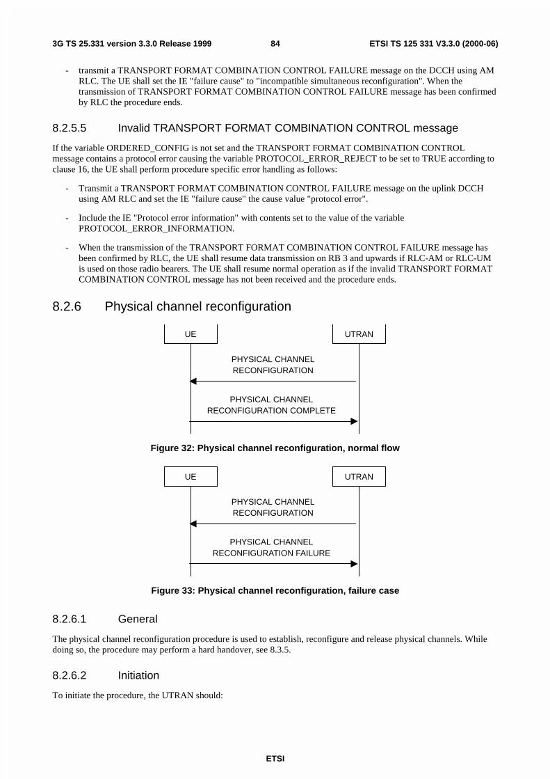
ETSI
ETSI TS 125 331 V3.3.0 (2000-06)843G TS 25.331 version 3.3.0 Release 1999
- transmit a TRANSPORT FORMAT COMBINATION CONTROL FAILURE message on the DCCH using AMRLC. The UE shall set the IE "failure cause" to "incompatible simultaneous reconfiguration". When thetransmission of TRANSPORT FORMAT COMBINATION CONTROL FAILURE message has been confirmedby RLC the procedure ends.
8.2.5.5 Invalid TRANSPORT FORMAT COMBINATION CONTROL message
If the variable ORDERED_CONFIG is not set and the TRANSPORT FORMAT COMBINATION CONTROLmessage contains a protocol error causing the variable PROTOCOL_ERROR_REJECT to be set to TRUE according toclause 16, the UE shall perform procedure specific error handling as follows:
- Transmit a TRANSPORT FORMAT COMBINATION CONTROL FAILURE message on the uplink DCCHusing AM RLC and set the IE "failure cause" the cause value "protocol error".
- Include the IE "Protocol error information" with contents set to the value of the variablePROTOCOL_ERROR_INFORMATION.
- When the transmission of the TRANSPORT FORMAT COMBINATION CONTROL FAILURE message hasbeen confirmed by RLC, the UE shall resume data transmission on RB 3 and upwards if RLC-AM or RLC-UMis used on those radio bearers. The UE shall resume normal operation as if the invalid TRANSPORT FORMATCOMBINATION CONTROL message has not been received and the procedure ends.
8.2.6 Physical channel reconfiguration
UE UTRAN
PHYSICAL CHANNELRECONFIGURATION
PHYSICAL CHANNELRECONFIGURATION COMPLETE
Figure 32: Physical channel reconfiguration, normal flow
UE UTRAN
PHYSICAL CHANNELRECONFIGURATION
PHYSICAL CHANNELRECONFIGURATION FAILURE
Figure 33: Physical channel reconfiguration, failure case
8.2.6.1 General
The physical channel reconfiguration procedure is used to establish, reconfigure and release physical channels. Whiledoing so, the procedure may perform a hard handover, see 8.3.5.
8.2.6.2 Initiation
To initiate the procedure, the UTRAN should:

ETSI
ETSI TS 125 331 V3.3.0 (2000-06)853G TS 25.331 version 3.3.0 Release 1999
- Configure new radio links in any new physical channel configuration and start transmission and reception on thenew radio links.
- transmit a PHYSICAL CHANNEL RECONFIGURATION message on the downlink DCCH using AM or UMRLC.
If the Physical Channel Reconfiguration procedure is simultaneous with SRNS relocation procedure, and cipheringand/or integrity protection are activated, transmit new ciphering and/or integrity protection information to be used afterreconfiguration.
UTRAN should take the UE capabilities into account when setting the new configuration.
If the message is used to initiate a transition from CELL_DCH to CELL_FACH state, the UTRAN may assign acommon channel configuration of a given cell and C-RNTI to be used in that cell to the UE.
8.2.6.3 Reception of a PHYSICAL CHANNEL RECONFIGURATION message by theUE in CELL_DCH state
Upon reception of a PHYSICAL CHANNEL RECONFIGURATION message, the UE shall perform the followingactions.
The UE shall store the received UE Information Elements, RB Information Elements, TrCH Information Elements andPhyCH information elements in the variable ORDERED_CONFIG.
The UE shall act upon all received information elements as specified in 8.5.7, unless specified otherwise in thefollowing.
The UE shall be able to receive an PHYSICAL CHANNEL RECONFIGURATION message and perform a hardhandover, even if no prior UE measurements have been performed on the target cell and/or frequency.
The UE shall suspend data transmission on RB 3 and upward, if RLC-AM or RLC-UM is used on those radio bearers.
If the IE "New C-RNTI" is included, the UE shall:
- Use that C-RNTI when using common physical channels of type RACH, FACH and CPCH in the current cell.
The UE should turn off the transmitter during the reconfiguration. The UE may first release the current physical channelconfiguration and shall then establish a new physical channel configuration according to 8.5.7 and the following.
If neither the IE "PRACH info" nor IE "Uplink DPCH info" is included, the UE shall:
- Let the physical channel of type PRACH that is given in system information be the default in uplink.
If neither the IE "Secondary CCPCH info" nor IE "Downlink DPCH info" is included, the UE shall:
- Start to receive the physical channel of type Secondary CCPCH that is given in system information.
In FDD, if the IE 'PDSCH code mapping' is included but the IE 'PDSCH with SHO DCH Info' is not included and if theDCH has only one link in its active set then the UE shall act upon the 'PDSCH code mapping' IE as specified insubclause 8.5.7 and:
- Infer that the PDSCH will be transmitted from the BS from which the downlink DPCH is transmitted.
The UE shall use the physical channel(s) applicable for the physical channel types that is used. If IE "TFS" is neitherincluded nor previously stored in the UE for that physical channel(s), the UE shall:
- Use the TFS given in system information.
If none of the TFS stored is compatible with the physical channel, the UE shall:
- Delete stored TFS and use the TFS given in system information.
If the PHYSICAL CHANNEL RECONFIGURATION message is used to initiate a state transition to the CELL_FACHstate and if an IE "Primary CCPCH info" in TDD or "Primary CPICH info" in FDD and IE "New C-RNTI" to a givencell is included, the UE shall:

ETSI
ETSI TS 125 331 V3.3.0 (2000-06)863G TS 25.331 version 3.3.0 Release 1999
- Select the cell indicated by the IE "Primary CCPCH info" in TDD or "Primary CPICH info" in FDD.
- Use the C-RNTI when using common transport channels of type RACH, FACH and CPCH in that given cellafter having completed the transition to that cell.
The UE shall enter a state according to 8.5.8.
The UE shall transmit a PHYSICAL CHANNEL RECONFIGURATION COMPLETE message on the uplink DCCHusing AM RLC.
If the variable RB_UPLINK_CIPHERING_ACTIVATION_TIME_INFO is set, the UE shall include and set the IE"Radio bearer uplink ciphering activation time info" to the value of that variable.
When the transmission of the PHYSICAL CHANNEL RECONFIGURATION COMPLETE message has beenconfirmed by RLC, the UE shall clear the variable ORDERED_CONFIG, clear the variableRB_UPLINK_CIPHERING_ACTIVATION_TIME_INFO, the UE shall resume data transmission on RB 3 andupwards if RLC-AM or RLC-UM is used on those radio bearers and the procedure ends.
If the PHYSICAL CHANNEL RECONFIGURATION message is used to initiate a transition from CELL_DCH toCELL_FACH state, the PHYSICAL CHANNEL RECONFIGURATION COMPLETE message shall be transmitted onthe RACH after the UE has completed the state transition. The UE shall clear the variable ORDERED_CONFIG, clearthe variable RB_UPLINK_CIPHERING_ACTIVATION_TIME_INFO and the procedure ends.
8.2.6.4 Reception of PHYSICAL CHANNEL RECONFIGURATION by the UE inCELL_FACH state
The UE shall store the received UE Information Elements, RB Information Elements, TrCH Information Elements andPhyCH information elements in the variable ORDERED_CONFIG.
The UE shall act upon all received information elements as specified in 8.5.7, unless specified otherwise in thefollowing.
If the IE "New C-RNTI" is included, the UE shall:
- Use that C-RNTI when using common physical channels of type RACH, FACH and CPCH in the current cell.
If neither the IE "PRACH info" nor IE "Uplink DPCH info" is included, the UE shall:
- Let the physical channel of type PRACH that is given in system information be the default in uplink.
If neither the IE "Secondary CCPCH info" nor IE "Downlink DPCH info" is included, the UE shall:
- Start to receive the physical channel of type Secondary CCPCH that is given in system information.
In FDD, if the IE 'PDSCH code mapping' is included but the IE 'PDSCH with SHO DCH Info' is not included then theUE shall act upon the 'PDSCH code mapping' IE as specified in subclause 8.5.7 and:
- Infer that the PDSCH will be transmitted from the BS from which the downlink DPCH is transmitted (therebeing only one link in the active set).
The UE shall use the physical channel(s) applicable for the physical channel types that is used. If neither the IE "TFS" isincluded or previously stored in the UE for that physical channel(s), the UE shall:
- Use the TFS given in system information.
If none of the TFS stored is compatible with the physical channel, the UE shall:
- Delete stored TFS and use the TFS given in system information.
The UE shall transmit a PHYSICAL CHANNEL RECONFIGURATION COMPLETE message on the uplink DCCHusing AM RLC.
If the variable RB_UPLINK_CIPHERING_ACTIVATION_TIME_INFO is set, the UE shall include and set the IE"Radio bearer uplink ciphering activation time info" to the value of that variable.

ETSI
ETSI TS 125 331 V3.3.0 (2000-06)873G TS 25.331 version 3.3.0 Release 1999
When the transmission of the PHYSICAL CHANNEL RECONFIGURATION COMPLETE message has beenconfirmed by RLC, the UE shall enter a state according to subclause 8.5.8 applied on the PHYSICAL CHANNELRECONFIGURATION message. If the UE ends up in the CELL_PCH or URA_PCH state, it shall delete its C-RNTI.The UE shall clear the variable ORDERED_CONFIG, clear the variableRB_UPLINK_CIPHERING_ACTIVATION_TIME_INFO and the procedure ends.
8.2.6.5 Reception of a PHYSICAL CHANNEL RECONFIGURATION COMPLETEmessage by the UTRAN
When UTRAN has received the PHYSICAL CHANNEL RECONFIGURATION COMPLETE message, UTRAN maydelete any old configuration and the procedure ends on the UTRAN side.
UTRAN may delete the C-RNTI of the UE if the procedure caused the UE to leave the CELL_FACH state.
If the IE "UL Timing Advance" is included, UTRAN shall evaluate the timing advance value that the UE has to use inthe new cell after handover.
8.2.6.6 Unsupported or unacceptable configuration in the UE
If the UE instructs the UE to use a configuration, which it does not support or if the variableUNACCEPTABLE_CONFIGURATION is set to TRUE, the UE shall
- transmit a PHYSICAL CHANNEL RECONFIGURATION FAILURE message on the DCCH using AM RLCand shall set the cause value in IE "failure cause" to "configuration unacceptable".
When the transmission of the PHYSICAL CHANNEL RECONFIGURATION FAILURE message has been confirmedby RLC, the UE shall clear the variable ORDERED_CONFIG and the procedure ends.
8.2.6.7 Physical channel failure
If the UE failed to establish the physical channel(s) indicated in the PHYSICAL CHANNEL RECONFIGURATIONmessage the UE shall:
- Revert to the configuration prior to the reception of the PHYSICAL CHANNEL RECONFIGURATIONmessage (old configuration) and transmit a PHYSICAL CHANNEL RECONFIGURATION FAILURE messageon the DCCH using AM RLC and shall set the cause value in IE "failure cause" to "physical channel failure".The procedure ends and the UE resumes the normal operation as if no physical channel reconfiguration attempthad occurred.
A physical channel failure occurs in case the criteria as defined in 8.5.4 are not fulfilled . If the UE is unable to revert tothe old configuration or if used, the activation time has expired, the UE shall:
- Initiate a RRC connection re-establishment procedure according to subclause 8.1.5
8.2.6.8 Reception of the PHYSICAL CHANNEL RECONFIGURATION FAILUREmessage by the UTRAN
When UTRAN has received the PHYSICAL CHANNEL RECONFIGURATION FAILURE message, UTRAN maydelete the new configuration and the procedure ends on the UTRAN side. Upper layers should be notified of the failure.
8.2.6.9 Non-receipt of PHYSICAL CHANNEL RECONFIGURATION COMPLETEmessage or PHYSICL CHANNEL RECONFIGURATION FAILURE messagein CELL_DCH state
If no PHYSICAL CHANNEL RECONFIGURATION COMPLETE message or PHYSICAL CHANNELRECONFIGURATION FAILURE message has been received, the UTRAN may delete the old and new configuration.If the UE requests a re-establishment of the RRC connection, before all UE dedicated resources have been cleared, thenew configuration may be re-assigned in the re-establishment procedure.
During transition from CELL_DCH to CELL_FACH, the UTRAN may also receive a CELL UPDATE message if theUE cannot use the assigned physical channel.

ETSI
ETSI TS 125 331 V3.3.0 (2000-06)883G TS 25.331 version 3.3.0 Release 1999
8.2.6.10 Non-receipt of PHYSICAL CHANNEL RECONFIGURATION COMPLETEmessage or PHYSICL CHANNEL RECONFIGURATION FAILURE messagein CELL_FACH state
If no PHYSICAL CHANNEL RECONFIGURATION COMPLETE message or PHYSICAL CHANNELRECONFIGURATION FAILURE message has been received, the UTRAN may delete the old and new configuration.If the UE makes a cell update before all UE dedicated resources have been cleared, the configuration procedure can berestarted.
8.2.6.11 Physical channel failure during transition from CELL_DCH to CELL_FACH
If the UE fails to select the cell, which was assigned in the PHYSICAL CHANNEL RECONFIGURATION messageinitiating transition from CELL_DCH to CELL_FACH, the UE shall perform cell and initiate the cell update procedure.
8.2.6.12 Subsequently received PHYSICAL CHANNEL RECONFIGURATIONmessages
If the variable ORDERED_CONFIG is set because of a PHYSICAL CHANNEL RECONFIGURATION messagepreviously received, the UE shall
- ignore the subsequently received PHYSICAL CHANNEL RECONFIGURATION message
- keep the configuration as before the subsequent PHYSICAL CHANNEL RECONFIGURATION message wasreceived.
8.2.6.13 Incompatible simultaneous reconfiguration
If the variable ORDERED_CONFIG is set (because of any message other than PHYSICAL CHANNELRECONFIGURATION) upon the reception of the PHYSICAL CHANNEL RECONFIGURATION message, the UEshall
- keep the old configuration as before the PHYSICAL CHANNEL RECONFIGURATION message was received
- transmit a PHYSICAL CHANNEL RECONFIGURATION FAILURE message on the DCCH using AM RLC.The UE shall set the IE "failure cause" to "incompatible simultaneous reconfiguration". When the transmissionof PHYSICAL CHANNEL RECONFIGURATION FAILURE message has been confirmed by RLC theprocedure ends.
8.2.6.14 Invalid PHYSICAL CHANNEL RECONFIGURATION message
If the variable ORDERED_CONFIG is not set and the PHYSICAL CHANNEL RECONFIGURATION messagecontains a protocol error causing the variable PROTOCOL_ERROR_REJECT to be set to TRUE according to clause16, the UE shall perform procedure specific error handling as follows:
- Transmit a PHYSICAL CHANNEL RECONFIGURATION FAILURE message on the uplink DCCH using AMRLCand set the IE "failure cause" the cause value "protocol error".
- Include the IE "Protocol error information" with contents set to the value of the variablePROTOCOL_ERROR_INFORMATION.
- When the transmission of the PHYSICAL CHANNEL RECONFIGURATION FAILURE message has beenconfirmed by RLC, the UE shall resume data transmission on RB 3 and upwards if RLC-AM or RLC-UM isused on those radio bearers. The UE shall resume normal operation as if the invalid PHYSICAL CHANNELRECONFIGURATION message has not been received and the procedure ends.

ETSI
ETSI TS 125 331 V3.3.0 (2000-06)893G TS 25.331 version 3.3.0 Release 1999
8.2.7 Physical Shared Channel Allocation [TDD only]
UE UTRAN
PHYSICAL SHARED CHANNEL ALLOCATION
Figure 34: Physical Shared Channel Allocation
8.2.7.1 General
The purpose of this procedure is to allocate physical resources to USCH or DSCH transport channels in TDD mode, fortemporary usage by a UE.
8.2.7.2 Initiation
The UE is in the CELL_FACH or CELL_DCH state, and at least one RB using USCH or DSCH has been established.
The UTRAN sends the "PHYSICAL SHARED CHANNEL ALLOCATION" message via the SHCCH, to allocatePUSCH or PDSCH resources to exactly one CCTrCH. The C-RNTI shall be included for UE identification. InCELL_DCH state, the message may also be transmitted on DCCH mapped to DCH transport channel. Whentransmitted on DCCH, there is no need to include the C-RNTI.
8.2.7.3 Reception of a PHYSICAL SHARED CHANNEL ALLOCATION message bythe UE
The UE shall check the C-RNTI to see if the UE is addressed by the message if the C-RNTI is included. If the UE isaddressed by the message, i.e using C-RNTI or the message is received on a physical resource that is assigned to onlythis UE, the UE shall evaluate the message and use the IEs as specified below.
If the IE "PDSCH info" is included, the UE shall:
- decode the IE " Allocation Activation Time" and the IE "Allocation Duration", to determine the time interval forwhich the allocation shall be valid;
- configure Layer 1 according to the PDSCH information received in allocation message or in BCCH SIB#6 (asdefault if not specified in allocation message), for the specified time interval received in allocation message;
- start receiving the PDSCH where the TFCI is included;
- receive the PDSCHs, and decode and demultiplex them into the respective DSCH channels according to theTFCI.
If the IE "PUSCH info" is included, the UE shall:
- decode the IE " Allocation Activation Time" and the IE "Allocation Duration", to determine the time interval forwhich the allocation shall be valid;
- configure Layer 1 according to the PUSCH information received in allocation message or in BCCH SIB#6 (asdefault if not specified in allocation message), for the specified time interval received in allocation message;
- determine the TFCS subset and hence the TFCI values which are possible given the PUSCH allocation for thatCCTrCH;
- configure the MAC-c/sh in the UE with this TFCS restriction if necessary;
- transmit USCH Transport Block Sets as required, within the TFCS limits given by the PUSCH allocation.
In addition, the UE shall evaluate the IE "PUSCH Allocation Pending" parameter: If its value is "pending", the UEstarts a timer T311. As long as this timer is running, the UE is not allowed to use the RACH for potential USCHcapacity requests. See the USCH CAPACITY REQUEST procedure.

ETSI
ETSI TS 125 331 V3.3.0 (2000-06)903G TS 25.331 version 3.3.0 Release 1999
In addition if the message contains an optional IE "Uplink Timing Advance" the UE shall configure the Layer 1 withthe new Timing Advance.
NOTE: If UE has just entered a new cell and SIB#6 USCH or DSCH information has not yet been scheduled,USCH/DSCH information is specified in allocation message.
8.2.8 PUSCH capacity request [TDD only]
UE UTRAN
PUSCH CAPACITY REQUEST
PHYSICAL SHARED CHANNEL ALLOCATION
Figure 35: PUSCH Capacity request procedure
8.2.8.1 General
With this procedure, the UE transmits its request for PUSCH resources to the UTRAN. In the normal case, the UTRANresponds with a PHYSICAL SHARED CHANNEL ALLOCATION message, which either allocates the requestedPUSCH resources, and/or allocates a PDSCH resource, or may just serve as an acknowledgement, indicating thatPUSCH allocation is pending.
With the PUSCH CAPACITY REQUEST message, the UE can request capacity for one or more USCH.
NOTE: Triggering of the capacity request is controlled by the measurement control procedure.
8.2.8.2 Initiation
The UE is in the CELL_FACH or CELL_DCH state, and at least one RB using USCH has been established. The RRCin the UE sees the requirement to request physical resources (PUSCH) for an USCH channel.
The RRC decides to send a PUSCH capacity request on the SHCCH. This is possible if:
- Timer T311 is not running.
- The timer T310 (capacity request repetition timer) is not running.
So the UE sends a PUSCH CAPACITY REQUEST message on the uplink SHCCH, resets counter V310, and startstimer T310.
With one PUSCH CAPACITY REQUEST message, capacity for one or more USCH can be requested. It shall includethese information elements:
- C-RNTI to be used as UE identity if the message is sent on RACH;
- Radio Bearer ID, for each radio bearer requiring capacity on USCH;
- RLC buffer payload for these radio bearers.
As an option, the message may include "Timeslot ISCP" and "Primary CCPCH RSCP".
The timeslots for which "Timeslot ISCP" may be reported shall have been configured with a previous PHYSICALSHARED CHANNEL ALLOCATION message.
8.2.8.3 Reception of a PUSCH CAPACITY REQUEST message by the UTRAN
The UTRAN should send a PHYSICAL SHARED CHANNEL ALLOCATION message to the UE, either for allocatingPUSCH or PDSCH resources, or just as an acknowledgement, announcing a pending PUSCH allocation.

ETSI
ETSI TS 125 331 V3.3.0 (2000-06)913G TS 25.331 version 3.3.0 Release 1999
8.2.8.4 Reception of a PHYSICAL SHARED CHANNEL ALLOCATION message bythe UE
Once the UE receives this message with the correct C-RNTI included, it shall stop the timer T310 and shall evaluate themessage as described in the Physical Shared Channel Allocation procedure. In particular, it shall take the IE "PUSCHAllocation Pending" into account: If this IE has the value "pending", the UE shall start the timer T311. As long as thistimer is running, the UE is prohibited to send PUSCH Capacity Requests on the SHCCH.
If the IE "PUSCH Allocation Pending" indicates "not pending", the UE shall stop the timer T311, and is allowed to sendPUSCH Capacity Requests on the SHCCH again.
If the PUSCH capacity allocated in this message is not sufficient for all the USCH transmission requests which the UEmay have, the RRC in the UE may decide to issue further PUSCH Capacity Requests - provided timer T311 is notrunning.
8.2.8.5 T310 time out
Upon expiry of timer T310, the UE shall
- If V310 is equal to or smaller than N310, transmit a new PUSCH CAPACITY REQUEST message on theUplink SHCCH, restart timer T310 and increase counter V310. The UE shall set the IEs in the PUSCHCAPACITY REQUEST message as specified above.
8.2.8.6 Maximum number of re-attempts exceeded
In this case the UE stops the procedure. It can start another PUSCH capacity request procedure if the UE-RRC sees theneed for it.
8.2.9 Downlink outer loop control
UE UTRAN
DOWNLINK OUTER LOOPCONTROL
Figure 36: Downlink Outer Loop Control, normal flow
8.2.9.1 General
The downlink outer loop control procedure is used to control the downlink outer loop power control running in the UE.
8.2.9.2 Initiation
The UTRAN may transmit the DOWNLINK OUTER LOOP CONTROL message on the downlink DCCH using AM orUM RLC.
To prevent the UE from increasing its DL SIR target value above its current value, the UTRAN should set the"Downlink Outer Loop Control" IE to "Increase not allowed".
To remove the previous restriction on the downlink outer loop power control, the UTRAN should set the "DownlinkOuter Loop Control" IE to "Increase allowed".

ETSI
ETSI TS 125 331 V3.3.0 (2000-06)923G TS 25.331 version 3.3.0 Release 1999
8.2.9.3 Reception of DOWNLINK OUTER LOOP CONTROL message by the UE
Upon reception of the DOWNLINK OUTER LOOP CONTROL message, the UE shall perform actions specified in8.5.7 unless otherwise specified below.
The UE shall read the IE "Downlink Outer Loop Control".
If the IE "Downlink Outer Loop Control" is set to "Increase not allowed", the UE shall prevent its DL SIR target valuefrom increasing above the current value.
If the IE "Downlink Outer Loop Control" is set to "Increase allowed", the UE shall remove the above restriction.
8.2.9.4 Invalid DOWNLINK OUTER LOOP CONTROL message
If the UE receives a DOWNLINK OUTER LOOP CONTROL message, which contains a protocol error causing thevariable PROTOCOL_ERROR_REJECT to be set to TRUE according to clause 16, the UE shall perform procedurespecific error handling as follows:
- Transmit an RRC STATUS message on the uplink DCCH using AM RLC and include the IE "Protocol errorinformation" with contents set to the value of the variable PROTOCOL_ERROR_INFORMATION.
- When the transmission of the RRC STATUS message has been confirmed by RLC, the UE shall resume normaloperation as if the invalid DOWNLINK OUTER LOOP CONTROL message has not been received.
8.2.10 Uplink Physical Channel Control
UE UTRAN
UPLINK PHYSICAL CHANNELCONTROL
Figure 37: Uplink Physical Channel Control
8.2.10.1 General
The uplink physical channel control procedure is used to control the uplink outer loop power control and timingadvance running in the UE in TDD.
8.2.10.2 Initiation
The UTRAN initiates the procedure by transmitting the UPLINK PHYSICAL CHANNEL CONTROL message on thedownlink DCCH using AM or UM RLC in order to update parameters for uplink open loop power control in the UE forone CCTrCH or to inform the UE about a new timing advance value to be applied. Especially, uplink interferenceinformation measured by the UTRAN can be included for the uplink timeslots used for the CCTrCH.
8.2.10.3 Reception of UPLINK PHYSICAL CHANNEL CONTROL message by the UE
Upon reception of the UPLINK PHYSICAL CHANNEL CONTROL message, the UE shall act upon all receivedinformation elements as specified in 8.5.7.
If Uplink DPCH Power Control Info, Constant Value, or list of UL Timeslot Interference IE's are transmitted, thisinformation shall be taken into account by the UE for uplink open loop power control as specified in 8.5.9.
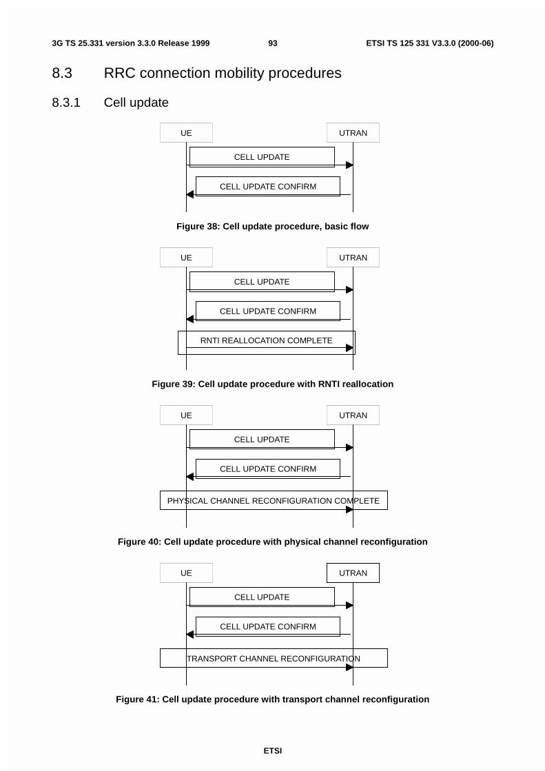
ETSI
ETSI TS 125 331 V3.3.0 (2000-06)933G TS 25.331 version 3.3.0 Release 1999
8.3 RRC connection mobility procedures
8.3.1 Cell update
UE UTRAN
CELL UPDATE
CELL UPDATE CONFIRM
Figure 38: Cell update procedure, basic flow
UE UTRAN
CELL UPDATE
CELL UPDATE CONFIRM
RNTI REALLOCATION COMPLETE
Figure 39: Cell update procedure with RNTI reallocation
UE UTRAN
CELL UPDATE
CELL UPDATE CONFIRM
PHYSICAL CHANNEL RECONFIGURATION COMPLETE
Figure 40: Cell update procedure with physical channel reconfiguration
UE UTRAN
CELL UPDATE
CELL UPDATE CONFIRM
TRANSPORT CHANNEL RECONFIGURATION
Figure 41: Cell update procedure with transport channel reconfiguration

ETSI
ETSI TS 125 331 V3.3.0 (2000-06)943G TS 25.331 version 3.3.0 Release 1999
8.3.1.1 General
The main purpose of the cell update procedure is to update UTRAN with the current cell of the UE after cell reselectionin CELL_FACH or CELL_PCH state. It may also be used for supervision of the RRC connection, even if no cellreselection takes place. The cell update procedure can also be used to reset the AM RLC entities for the signalling linkand the u-plane link. The UE can use a CELL UPDATE message to notify the unrecoverable error (Amount of theretransmission of RESET PDU reaches the value of Max DAT and receives no ACK) in an AM RLC entity for thesignalling link.
NOTE: PHYSICAL/TRANSPORT CHANNEL RECONFIGURATION COMPLETE message is only used whencommon channels are configured (doesn't apply to dedicated channels)
8.3.1.2 Initiation
A UE in CELL_FACH, CELL_PCH or URA_PCH state may apply the cell update procedure for a number of purposes.The specific requirements the UE shall take into account for each case are specified in the following:
- Upon initiation of the procedure, the UE shall set the variable PROTOCOL_ERROR_INDICATOR to FALSE.
- In CELL_FACH or CELL_PCH state, the UE shall perform the cell update procedure when selecting anothercell (cell reselection).
- In CELL_FACH and CELL_PCH state, the UE shall perform the cell update procedure upon expiry of T305while the UE is in the service area. The UE shall only perform this periodic cell updating if configured by meansof the IE "Information for periodical cell and URA update" in System Information Block Type 2. The UE shallinitially start timer T305 upon entering CELL_FACH or CELL_PCH state (periodic cell update).
- In transition to CELL_DCH to CELL_FACH by receiving RB control message with no indication which cell tocamp, the UE should select a cell and perform the cell update procedure (RB control response).
- In CELL_PCH state and URA_PCH state, the UE shall initiate the cell update procedure if it wants to transmitUL data (UL data transmission).
- In CELL_PCH and URA_PCH state, the UE shall perform the cell update procedure when receiving a PAGINGTYPE 1 message as in subclause 8.1.2.3 (paging response).
- moving to CELL_FACH state, if not already in that state.
- consider stored C-RNTI to be invalid until CELL UPDATE CONFIRM message is received when UE detects anew cell.
- suspend data transmission on RB 3 and upward, if RLC-AM or RLC-UM is used on those radio bearers.
- sending a CELL UPDATE message on the uplink CCCH.
- starting timer T302 and resetting counter V302.
The IE "cell update cause" shall be used as follows:
- In case of cell reselection: "cell reselection";
- In case of periodic cell updating: "periodic cell update";
- In case of RB control response: "RB control response";
- In case of UL data transmission: "UL data transmission";
- In case of paging response: "paging response".
If the value of the variable PROTOCOL_ERROR_INDICATOR is TRUE, the UE shall set the IE "Protocol errorindicator" to TRUE and include the IE "Protocol error information" set to the value of the variablePROTOCOL_ERROR_INFORMATION.
If the value of the variable PROTOCOL_ERROR_INDICATOR is FALSE, the UE shall set the IE "Protocol errorindicator" to FALSE.

ETSI
ETSI TS 125 331 V3.3.0 (2000-06)953G TS 25.331 version 3.3.0 Release 1999
The IE "AM_RLC error indication" shall be set when the UE detects unrecoverable error (amount of the retransmissionof RESET PDU reaches the value of Max DAT and receives no ACK) in an AM RLC entity for the signalling link. TheIE "AM_RLC error indication (for u-plane)" shall be set when the UE detects unrecoverable error in an AM RLC entity(for u-plane) for for u-plane link.
UE shall include "the maximum value in the currently used HFNs among CS and PS domains" + "1" in IE "HFN" inCELL UPDATE message.
The UE shall include an intra-frequency measurement report in the CELL UPDATE message, as specified in the IE"Intra-frequency reporting quantity for RACH reporting" and the IE "Maximum number of reported cells on RACH" insystem information block type 12.
8.3.1.3 T305 expiry and the UE detects that it is out of service area
When the T305 expires and the UE detects that it is out of service area that is specified in subclause 8.5.5, the UE shall
- start timer T307;
- search for cell to camp.
8.3.1.3.1 Re-entering of service area
When the UE detects that it is no longer out of service area before the expiry of T307, the UE shall:
- transmit a CELL UPDATE message on the uplink CCCH
8.3.1.3.2 Expiry of timer T307
When the T307 expires, the UE shall:
- move to idle mode;
- release all dedicated resources;
- indicate a RRC connection failure to the non-access stratum.
Other actions the UE shall perform when entering idle mode from connected mode are specified in subclause 8.5.2.
8.3.1.4 Reception of an CELL UPDATE message by the UTRAN
When the UTRAN receives a CELL UPDATE message, it should transmit a CELL UPDATE CONFIRM message onthe downlink DCCH.
When the UTRAN detects AM_RLC unrecoverable error (Amount of the retransmission of RESET PDU reaches thevalue of Max DAT and receives no ACK), it waits for CELL UPDATE message from the UE and when the UTRANreceives it, UTRAN commands the UE to reset AM_RLC by sending CELL UPDATE CONFIRM message. Thisprocedure can be used not only in the case of AM_RLC unrecoverable error but also in the case that UTRAN wants toreset AM_RLC for other reasons such as in the case when SRNC Relocation is initiated without keeping RLC status(current counters) from old SRNC to new SRNC.
8.3.1.5 Reception of the CELL UPDATE CONFIRM message by the UE
Upon receiving the CELL UPDATE CONFIRM message (old C-RNTI or U-RNTI may be used for MAC header), theUE shall stop timer T302.
The UE shall delete old C-RNTI when a new C-RNTI is allocated. If not allocated, use old C-RNTI as a valid C-RNTI.
The UE shall act upon all received information elements as specified in 8.5.7, unless specified otherwise in thefollowing.
If the CELL UPDATE CONFIRM message includes the IE "CN domain identity" and the IE "NAS systeminformation", the UE shall forward the content of the IE "NAS system information" to the non-access stratum entity ofthe UE identified by the IE "CN domain identity".

ETSI
ETSI TS 125 331 V3.3.0 (2000-06)963G TS 25.331 version 3.3.0 Release 1999
If the CELL UPDATE CONFIRM message includes the IE "URA-Id" the UE shall store this URA identity.
If IE "DRX indicator" in the CELL UPDATE CONFIRM message is not set to "no DRX", no RRC response message issent to the UTRAN.
If the CELL UPDATE CONFIRM message does not include IE "new C-RNTI", IE "new U-RNTI", IE "PRACH info"nor IE "Secondary CCPCH info", following actions are taken;
- If cell update is due to "periodical cell update", no RRC response message is sent to the UTRAN.
- If cell update is due to "UL data transmission" or "paging response" and if there is no difference in TFS and/orTFCS stored in UE compared to PRACH/SCCPCH indicated in the broadcast system information, PHYSICALCHANNEL RECONFIGURATION COMPLETE message is sent to the UTRAN using the PRACH indicated inthe broadcast system information.
- If cell update is due to "UL data transmission" or "paging response" and if there is a difference in TFS and/orTFCS stored in UE compared to PRACH/SCCPCH indicated in the broadcast system information,,TRANSPORT CHANNEL RECONFIGURATION COMPLETE message is sent to the UTRAN using thePRACH indicated in the broadcast system information.
- No case for cell update due to "cell reselection" or "RB control response".
If the CELL UPDATE CONFIRM message includes the IE "new C-RNTI" and optionally the IE "new U-RNTI" butdoes not include IE "PRACH info" or IE "Secondary CCPCH info", the UE shall update its identities and followingactions are taken:
- If cell update is due to "periodical cell update", transmit an RNTI REALLOCATION COMPLETE message onthe uplink DCCH using the PRACH stored in the UE.
- If cell update is due to "cell reselection", "UL data transmission" or "paging response" and if there is nodifference in TFS and/or TFCS stored in UE compared to PRACH/SCCPCH indicated in the broadcast systeminformation, PHYSICAL CHANNEL RECONFIGURATION COMPLETE message is sent to the UTRANusing the PRACH indicated in the broadcast system information.
- If cell update is due to "UL data transmission" or "paging response" and if there is a difference in TFS and/orTFCS stored in UE compared to PRACH/SCCPCH indicated in the broadcast system information,,TRANSPORT CHANNEL RECONFIGURATION COMPLETE message is sent to the UTRAN using thePRACH indicated in the broadcast system information.
- If cell update is due to "RB control response", transmit a RB control response message on the uplink DCCHusing the PRACH indicated in the broadcast system information.
If the CELL UPDATE CONFIRM message includes the IE "RLC reset indicator (for C-plane)" the UE shall reset theAM RLC entities on C-plane.
If the CELL UPDATE CONFIRM message includes the IE "RLC reset indicator (for U-plane)" the UE shall reset theAM RLC entities on U-plane.
If the CELL UPDATE CONFIRM message includes the IE "PRACH info" and/or the IE "Secondary CCPCH info", theUE shall
- Perform the actions stated in subclauses 8.5.7.6.2 and 8.5.7.6.3.
- Update its identities if the CELL UPDATE CONFIRM message includes the IE new C-RNTI" and optionally theIE "new U-RNTI".
- If cell update is due to "periodical cell update", "cell reselection", "UL data transmission" or "paging response",transmit a PHYSICAL CHANNEL RECONFIGURATION COMPLETE message on the uplink DCCH usingthe PRACH indicated in CELL UPDATE CONFIRM message.
- If cell update is due to "RB control response", transmit a RB control response message on the uplink DCCHusing the PRACH indicated in the broadcast system information.
The UE shall enter a state according to subclause 8.5.8 applied on the CELL UPDATE CONFIRM message.

ETSI
ETSI TS 125 331 V3.3.0 (2000-06)973G TS 25.331 version 3.3.0 Release 1999
In case the UE ends in CELL_FACH or CELL_PCH state and periodic cell updating is configured, it shall reset timerT305.
In case the UE does not end in CELL_FACH state, it shall delete its C-RNTI and PRACH/SCCPCH information.
If the UE remains in CELL_FACH state and the CELL UPDATE CONFIRM message includes the IE "New C-RNTI"the UE shall then resume data transmission on RB 3 and upward, if RLC-AM or RLC-UM is used on those radiobearers.
8.3.1.6 Invalid CELL UPDATE CONFIRM message
If the UE receives an CELL UPDATE CONFIRM message, which contains a protocol error causing the variablePROTOCOL_ERROR_REJECT to be set to TRUE according to clause 16, the UE shall perform procedure specificerror handling as follows:
The UE shall check the value of V302 and
- If V302 is smaller or equal than N302, the UE shall set the variable PROTOCOL_ERROR_INDICATOR toTRUE, retransmit a CELL UPDATE message on the uplink CCCH, restart timer T302 and increase counterV302. The IE "Cell update cause" shall be set to the event causing the transmission of the CELL UPDATEmessage, see subclause 8.3.1.2.
- If V302 is greater than N302, the UE shall enter idle mode. The procedure ends and a connection failure may beindicated to the non-access stratum. Other actions the UE shall perform when entering idle mode from connectedmode are specified in subclause 8.5.2.
8.3.1.7 T302 expiry or cell reselection
- Upon expiry of timer T302; and/or
- upon reselection of another UTRA cell when waiting for the CELL UPDATE CONFIRM message,
the UE shall check the value of V302 and:
- If V302 is smaller or equal than N302, the UE shall retransmit a CELL UPDATE message on the uplink CCCH,restart timer T302 and increase counter V302. The IE "Cell update cause" shall be set to the event causing thetransmission of the CELL UPDATE message, see subclause 8.3.1.2.
- If V302 is greater than N302, the UE shall enter idle mode. The procedure ends and a connection failure may beindicated to the non-access stratum. Other actions the UE shall perform when entering idle mode from connectedmode are specified in subclause 8.5.2
8.3.1.8 Reception of the RNTI REALLOCATION COMPLETE message by theUTRAN
See subclause 8.3.3.4.
8.3.1.9 Reception of the PHYSICAL CHANNEL RECONFIGURATION COMPLETEmessage by the UTRAN
When the UTRAN receives PHYSICAL CHANNEL RECONFIGURATION message, the procedure ends.
8.3.1.10 Reception of the TRANSPORT CHANNEL RECONFIGURATIONCOMPLETE message by the UTRAN
When the UTRAN receives TRANSPORT CHANNEL RECONFIGURATION message, the procedure ends.

ETSI
ETSI TS 125 331 V3.3.0 (2000-06)983G TS 25.331 version 3.3.0 Release 1999
8.3.2 URA update
UE UTRAN
URA UPDATE
URA UPDATE CONFIRM
Figure 42: URA update procedure, basic flow
UE UTRAN
URA UPDATE
URA UPDATE CONFIRM
RNTI REALLOCATION COMPLETE
Figure 43: URA update procedure with RNTI reallocation
8.3.2.1 General
The main purpose of the URA update procedure is to update UTRAN with the current URA of the UE after URAreselection in URA_PCH state. It may also be used for supervision of the RRC connection, even if no URA reselectiontakes place. UTRAN registration areas may be hierarchical to avoid excessive signalling. This means that several URAidentifiers may be broadcast in one cell and that different UEs in one cell may reside in different URAs. A UE inURA_PCH state shall always have one and only one valid URA. The URA UPDATE CONFIRM message may alsocontain new NAS system information.
8.3.2.2 Initiation
A UE in URA_PCH state may apply the URA update procedure for a number of purposes. The specific requirementsthe UE shall take into account for each case are specified in the following:
- Upon initiation of the procedure, the UE shall set the variable PROTOCOL_ERROR_INDICATOR to FALSE.
- In URA_PCH state, the UE shall perform the URA update procedure when the current URA assigned to the UEis not present in the list of URA IDs broadcast in a cell.
- In URA_PCH state, the UE shall perform the URA update procedure upon expiry of T306 while the UE is in theservice area. The UE shall only perform this periodic URA updating if configured by means of the IE"Information for periodical cell and URA update" in System Information Block Type 2. The UE shall initiallystart timer T306 upon entering URA_PCH state.
The UE shall start the URA update procedure by:
- temporarily storing the list of URA IDs broadcast in a cell;
- moving to CELL_FACH state;
- sending a URA UPDATE message on the uplink CCCH;
- starting timer T303 and resetting counter V303.

ETSI
ETSI TS 125 331 V3.3.0 (2000-06)993G TS 25.331 version 3.3.0 Release 1999
The IE "URA update cause" shall be set as follows;
- in case of URA reselection, to: "URA reselection";
- in case of periodic URA updating, to: "periodic URA update".
If the value of the variable PROTOCOL_ERROR_INDICATOR is TRUE, the UE shall set the IE "Protocol errorindicator" to TRUE and include the IE "Protocol error information" set to the value of the variablePROTOCOL_ERROR_INFORMATION.
If the value of the variable PROTOCOL_ERROR_INDICATOR is FALSE, the UE shall set the IE "Protocol errorindicator" to FALSE.
8.3.2.3 T306 expiry and the UE detects that it is out of service area
When the T306 expires and the UE detects that it is out of service area, which is specified in subclause 8.5.5, the UEshall:
- start timer T307;
- search for cell to camp.
8.3.2.3.1 Re-entering of service area
When the UE detects that it is no longer out of service area before the expiry of T307, the UE shall:
- transmit URA UPDATE message on the uplink CCCH.
8.3.2.3.2 Expiry of timer T307
When the T307 expires, the UE shall:
- move to idle state;
- release all dedicated resources;
- indicate a RRC connection failure to the non-access stratum.
Other actions the UE shall perform when entering idle mode from connected mode are specified in subclause 8.5.2.
8.3.2.4 Reception of an URA UPDATE message by the UTRAN
When the UTRAN receives a URA UPDATE message, it should transmit a URA UPDATE CONFIRM message on thedownlink CCCH or DCCH.
The UTRAN should assign the URA ID to the UE in the URA UPDATE CONFIRM message in a cell where multipleURAs are valid.
8.3.2.5 Reception of an URA UPDATE CONFIRM message by the UE
Upon receiving the URA UPDATE CONFIRM message, the UE shall stop timer T303 and restart timer T306.If theURA UPDATE CONFIRM message includes the IEs "new C-RNTI" and optionally IE "new U-RNTI", the UE shall:
- update its identities and transmit an RNTI REALLOCATION COMPLETE message on the uplink DCCH usingthe PRACH indicated in the broadcast system information.
If the URA UPDATE CONFIRM message includes the IE "URA ID", the UE shall:
- confirm whether indicated URA ID is in the list of URA IDs which is temporarily stored in the UE;
- update URA ID and store in itself.
If the URA UPDATE CONFIRM message does not include the IE "URA ID", the UE shall:

ETSI
ETSI TS 125 331 V3.3.0 (2000-06)1003G TS 25.331 version 3.3.0 Release 1999
- confirm whether only one URA ID exists in the list of URA IDs which is temporarily stored in the UE;
- update URA ID and stored in itself.
If the URA UPDATE CONFIRM message includes the IEs "CN domain identity" and "NAS system information", theUE shall forward the content of the IE to the non-access stratum entity of the UE indicated by the IE "CN domainidentity".
The UE shall enter a state according to subclause 8.5.8 applied on the URA UPDATE CONFIRM message, unlessotherwise specified below.
If the UE does not end up in the CELL_FACH state, the UE shall, after other possible actions:
- retrieve secondary CCPCH info (for PCH) from the SYSTEM INFORMATION broadcast from the new cell;
- delete its C-RNTI; and
- the procedure ends.
8.3.2.6 Confirmation error of URA ID list
- When indicated URA ID is not included in the list of URA IDs; or
- when the URA ID is not indicated and the list of URA IDs includes more than one URA ID,
the UE shall check the value of V303, and:
- If V303 is smaller or equal than N303, the UE shall retransmit a URA UPDATE message on the uplink CCCH,restart timer T303 and increase counter V303. The UE shall set the IEs in the URA UPDATE message accordingto subclause 8.3.2.2. If V303 is greater than N303, the UE shall enter idle mode. The procedure ends and aconnection failure may be indicated to the non-access stratum. Other actions the UE shall perform when enteringidle mode from connected mode are specified in subclause 8.5.2
8.3.2.7 Invalid URA UPDATE CONFIRM message
If the UE receives an URA UPDATE CONFIRM message, which contains a protocol error causing the variablePROTOCOL_ERROR_REJECT to be set to TRUE according to clause 16, the UE shall perform procedure specificerror handling as follows:
The UE shall check the value of V303 and:
- If V303 is smaller or equal than N303, the UE shall set the variable PROTOCOL_ERROR_INDICATOR toTRUE, retransmit a URA UPDATE message on the uplink CCCH, restart timer T303 and increase counterV303. The UE shall the IEs in the URA UPDATE message according to subclause 8.3.2.2.
- If V303 is greater than N303, the UE shall enter idle mode. The procedure ends and a connection failure may beindicated to the non-access stratum. Other actions the UE shall perform when entering idle mode from connectedmode are specified in subclause 8.5.2.
8.3.2.8 T303 expiry or URA reselection
- Upon expiry of timer T303; and/or
- upon reselection of another UTRA cell when waiting for the URA UPDATE CONFIRM message,
the UE shall check the value of V303 and:
- If V303 is smaller or equal than N303, the UE shall retransmit a URA UPDATE message on the uplink CCCH,restart timer T303 and increase counter V303. The UE shall set the IEs in the URA UPDATE message accordingto subclause 8.3.2.2.
- If V303 is greater than N303, the UE shall enter idle mode. The procedure ends and a connection failure may beindicated to the non-access stratum. Other actions the UE shall perform when entering idle mode from connectedmode are specified in subclause 8.5.2.

ETSI
ETSI TS 125 331 V3.3.0 (2000-06)1013G TS 25.331 version 3.3.0 Release 1999
8.3.2.9 Reception of the RNTI REALLOCATION COMPLETE message by theUTRAN
See subclause 8.3.3.4.
8.3.3 RNTI reallocation
UE UTRAN
RNTI REALLOCATION
RNTI REALLOCATION COMPLETE
Figure 44: RNTI reallocation procedure, normal flow
UE UTRAN
RNTI REALLOCATION
RNTI REALLOCATION FAILURE
Figure 45: RNTI reallocation procedure, failure case
8.3.3.1 General
The purpose of this procedure is to allocate a new C-RNTI and/or U-RNTI to an UE in connected mode.
8.3.3.2 Initiation
To initiate the procedure UTRAN transmits an RNTI REALLOCATION message to the UE on the downlink DCCH.
8.3.3.3 Reception of RNTI REALLOCATION message by the UE
When the UE receives an RNTI REALLOCATION message, it shall take the following actions and then transmit anRNTI REALLOCATION COMPLETE message on the uplink DCCH. The procedure ends when the transmission of theRNTI REALLOCATION COMPLETE message has been confirmed by RLC.
If the IE "new U-RNTI" is present, the UE shall store and start to use the values of these IEs as the current U-RNTI.
If the IE "new C-RNTI" is present, the UE shall store and start to use the value of this IE.
If the IE "CN domain identity" and the IE "NAS system information" are included, the UE shall forward the content ofthe IE to the non-access stratum entity of the UE indicated by the IE "CN domain identity".
8.3.3.4 Reception of an RNTI REALLOCATION COMPLETE message by theUTRAN
When the network receives RNTI REALLOCATION COMPLETE message, UTRAN may delete any old C-RNTI andold U-RNTI. The procedure ends.

ETSI
ETSI TS 125 331 V3.3.0 (2000-06)1023G TS 25.331 version 3.3.0 Release 1999
8.3.3.5 Invalid RNTI REALLOCATION message
If the RNTI REALLOCATION message contains a protocol error causing the variable PROTOCOL_ERROR_REJECTto be set to TRUE according to clause 16, the UE shall perform procedure specific error handling as follows:
- transmit a RNTI REALLOCATION FAILURE message on the uplink DCCH using AM RLCand set the IE"failure cause" the cause value "protocol error";
- include the IE "Protocol error information" with contents set to the value of the variablePROTOCOL_ERROR_INFORMATION.
- When the transmission of the RNTI REALLOCATION FAILURE message has been confirmed by RLC, the UEshall resume normal operation as if the invalid RNTI REALLOCATION message has not been received and theprocedure ends.
8.3.4 Active set update in soft handover
UE UTRAN
ACTIVE SET UPDATE
ACTIVE SET UPDATE COMPLETE
Figure 46: Active Set Update procedure, successful case
UE UTRAN
ACTIVE SET UPDATE
ACTIVE SET UPDATE FAILURE
Figure 47: Active Set Update procedure, failure case
8.3.4.1 General
The purpose of the active set update procedure is to update the active set of the connection between the UE andUTRAN. This procedure shall be used in CELL_DCH state. The UE should keep on using the old RLs while allocatingthe new RLs. Also the UE should keep on using the transmitter during the reallocation process. This procedure is onlyused in FDD mode.
8.3.4.2 Initiation
The procedure is initiated when UTRAN orders a UE in CELL_DCH state, to make the following modifications of theactive set of the connection:
a) Radio link addition;
b) Radio link removal;
c) Combined radio link addition and removal.
In case a) and c), UTRAN should:
- prepare new additional radio link(s) in the UTRAN prior to the command to the UE.
In all cases, UTRAN should:

ETSI
ETSI TS 125 331 V3.3.0 (2000-06)1033G TS 25.331 version 3.3.0 Release 1999
- send an ACTIVE SET UPDATE message on downlink DCCH using AM or UM RLC.
UTRAN should include the following information:
- IE "Radio Link Addition Information": Downlink DPCH information and other optional parameters relevant forthe additional radio links with the IE "Primary CPICH info" used for the reference ID to indicate which radiolink to add. This IE is need in case a) and c);
- IE "Radio Link Removal Information": IE "Primary CPICH info" used for the reference ID to indicate whichradio link to remove. This IE is need in case b) and c).
If SRNC relocation is performed simultaneously during active set update procedure when all radio links are replacedsimultaneously, the UTRAN shall include the IE "U-RNTI" and IE "CN domain identity" and IE "NAS systeminformation" in the ACTIVE SET UPDATE messages.
8.3.4.3 Reception of an ACTIVE SET UPDATE message by the UE
- Upon reception of an ACTIVE SET UPDATE message the UE shall s tore the received IE "Radio Link AdditionInformation" and the IE "Radio Link Removal Information" to the variable ORDERED_ASU.
The UE shall act upon all received information elements as specified in 8.5.7, unless specified otherwise in thefollowing.
The UE shall:
- at first, add the RLs indicated in the IE "Radio Link Addition Information";
- remove the RLs indicated in the IE "Radio Link Removal Information" . If the UE active set is full or becomesfull, an RL, which is indicated to remove, shall be removed before adding RL, which is indicated to add;
- if the ACTIVE SET UPDATE message includes the IE "U-RNTI", update its identity;
- if the ACTIVE SET UPDATE message includes the IE "CN domain identity" and the IE "NAS systeminformation", the UE shall forward the content of the IE to the non-access stratum entity of the UE indicated bythe IE "CN domain identity";
- if the ACTIVE SET UPDATE message includes the IE 'TFCI combining indicator' associated with a radio linkto be added then the UE should configure Layer 1 to soft combine TFCI (field 2) of this new link with thoselinks already in the TFCI (field 2) combining set;
- transmit an ACTIVE SET UPDATE COMPLETE message on the uplink DCCH using AM RLC;
- if the variable RB_UPLINK_CIPHERING_ACTIVATION_TIME_INFO is set, the UE shall include and set theIE "Radio bearer uplink ciphering activation time info" to the value of that variable;
- when the transmission of the ACTIVE SET UPDATE COMPLETE message has been confirmed by RLC thecontents of the variable ORDERED_ASU shall be cleared, the UE shall clear the variableRB_UPLINK_CIPHERING_ACTIVATION_TIME_INFO and the procedure ends on the UE side.
8.3.4.4 Abnormal case: Unsupported configuration in the UE
- If UTRAN instructs the UE to use a configuration that it does not support; or
- If a radio link in the IE "Radio Link Removal Information" in the ACTIVE SET UPDATE message is not part ofthe active set,
the UE shall:
- keep the active set and the contents of the variable ORDERED_ASU, as it was before the ACTIVE SETUPDATE message was received;
- transmit an ACTIVE SET UPDATE FAILURE message on the DCCH using AM RLC;
- set the IE "failure cause" to "configuration unacceptable";

ETSI
ETSI TS 125 331 V3.3.0 (2000-06)1043G TS 25.331 version 3.3.0 Release 1999
- when the transmission of the ACTIVE SET UPDATE FAILURE message has been confirmed by RLC theprocedure ends on the UE side.
8.3.4.5 Reception of the ACTIVE SET UPDATE COMPLETE message by theUTRAN
When the UTRAN has received the ACTIVE SET UPDATE COMPLETE message,
- the UTRAN may remove radio link(s) that are indicated to remove to the UE in case b) and c); and
- the procedure ends on the UTRAN side.
8.3.4.6 Reception of the ACTIVE SET UPDATE FAILURE message by the UTRAN
When the UTRAN has received the ACTIVE SET UPDATE FAILURE message, the UTRAN may delete radio linksthat are indicated to add to the UE. The procedure ends on the UTRAN side.
8.3.4.7 Subsequently received ACTIVE SET UPDATE messages
If the variable ORDERED_CONFIG is set because of an ACTIVE SET UPDATE message previously received, the UEshall
- ignore the subsequently received ACTIVE SET UPDATE message
- keep the configuration as before the subsequent ACTIVE SET UPDATE message was received.
8.3.4.8 Incompatible simultaneous reconfiguration
If any of the variables ORDERED_CONFIG or ORDERED_ASU are set because of any message other than ACTIVESET UPDATE, the UE shall:
- Transmit an ACTIVE SET UPDATE FAILURE message on the DCCH using AM RLC. The UE shall set the IE"failure cause" to "incompatible simultaneous reconfiguration".
- When the transmission of the ACTIVE SET UPDATE FAILURE message has been confirmed by RLC theprocedure ends and the UE shall keep the active set and the contents of the variable ORDERED_ASU, as it wasbefore the ACTIVE SET UPDATE message was received.
8.3.4.9 Invalid ACTIVE SET UPDATE message
If none of the variables ORDERED_CONFIG or ORDERED_ASU are set and the ACTIVE SET UPDATE messagecontains a protocol error causing the variable PROTOCOL_ERROR_REJECT to be set to TRUE according to clause16, the UE shall perform procedure specific error handling as follows:
- Transmit a ACTIVE SET UPDATE FAILURE message on the uplink DCCH using AM RLCand set the IE"failure cause" the cause value "protocol error".
- Include the IE "Protocol error information" with contents set to the value of the variablePROTOCOL_ERROR_INFORMATION.
- When the transmission of the ACTIVE SET UPDATE FAILURE message has been confirmed by RLC, the UEshall resume normal operation as if the invalid ACTIVE SET UPDATE message has not been received and theprocedure ends.
8.3.5 Hard handover
8.3.5.1 General
The purposes of the hard handover procedure are;
- to change the frequency of the connection between the UE and UTRAN;
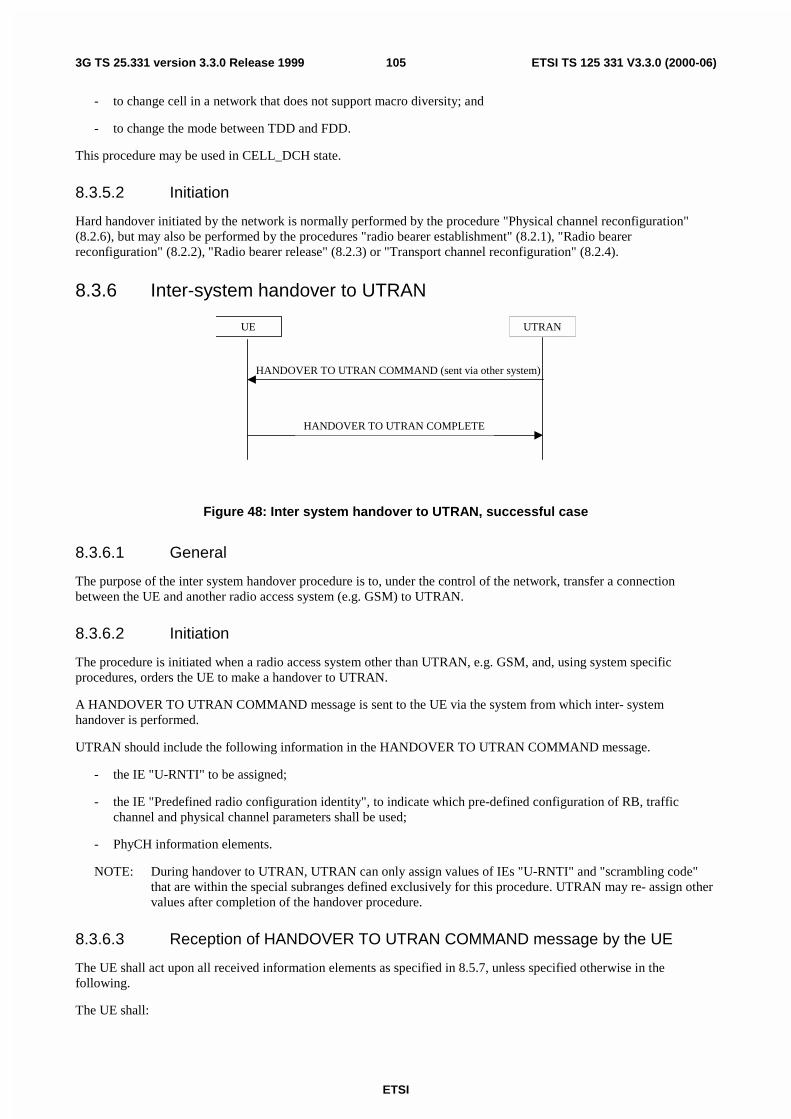
ETSI
ETSI TS 125 331 V3.3.0 (2000-06)1053G TS 25.331 version 3.3.0 Release 1999
- to change cell in a network that does not support macro diversity; and
- to change the mode between TDD and FDD.
This procedure may be used in CELL_DCH state.
8.3.5.2 Initiation
Hard handover initiated by the network is normally performed by the procedure "Physical channel reconfiguration"(8.2.6), but may also be performed by the procedures "radio bearer establishment" (8.2.1), "Radio bearerreconfiguration" (8.2.2), "Radio bearer release" (8.2.3) or "Transport channel reconfiguration" (8.2.4).
8.3.6 Inter-system handover to UTRAN
UE UTRAN
HANDOVER TO UTRAN COMMAND (sent via other system)
HANDOVER TO UTRAN COMPLETE
Figure 48: Inter system handover to UTRAN, successful case
8.3.6.1 General
The purpose of the inter system handover procedure is to, under the control of the network, transfer a connectionbetween the UE and another radio access system (e.g. GSM) to UTRAN.
8.3.6.2 Initiation
The procedure is initiated when a radio access system other than UTRAN, e.g. GSM, and, using system specificprocedures, orders the UE to make a handover to UTRAN.
A HANDOVER TO UTRAN COMMAND message is sent to the UE via the system from which inter- systemhandover is performed.
UTRAN should include the following information in the HANDOVER TO UTRAN COMMAND message.
- the IE "U-RNTI" to be assigned;
- the IE "Predefined radio configuration identity", to indicate which pre-defined configuration of RB, trafficchannel and physical channel parameters shall be used;
- PhyCH information elements.
NOTE: During handover to UTRAN, UTRAN can only assign values of IEs "U-RNTI" and "scrambling code"that are within the special subranges defined exclusively for this procedure. UTRAN may re- assign othervalues after completion of the handover procedure.
8.3.6.3 Reception of HANDOVER TO UTRAN COMMAND message by the UE
The UE shall act upon all received information elements as specified in 8.5.7, unless specified otherwise in thefollowing.
The UE shall:

ETSI
ETSI TS 125 331 V3.3.0 (2000-06)1063G TS 25.331 version 3.3.0 Release 1999
- store the value of the IE "U-RNTI"; and
- initiate the signalling link, the RB(s) and traffic channel(s) in accordance with the predefined parametersidentified by the IE "Predefined radio configuration identity";
- initiate the physical channels in accordance with the predefined parameters identified by the IE "Predefined radioconfiguration identity" and the received physical channel information elements;
- perform an open loop estimation to determine the UL transmission power, taking into account the received IE"Maximum allowed UL TX power" and move to CELL_DCH state;
- apply the same ciphering (ciphered/ unciphered, algorithm) as prior to inter system handover, unless a change ofalgorithm is requested by means of the "Ciphering algorithm".
The UE shall be able to receive a HANDOVER TO UTRAN COMMAND message and perform an inter-systemhandover, even if no prior UE measurements have been performed on the target UTRAN cell and/or frequency.
If the UE succeeds to establish the connection to UTRAN, it shall transmit a HANDOVER TO UTRAN COMPLETEmessage on the uplink DCCH. When the transmission of the HANDOVER TO UTRAN COMPLETE message has beenconfirmed by RLC, the procedure ends.
8.3.6.4 Invalid Handover to UTRAN command message
If the UE receives a HANDOVER TO UTRAN COMMAND message, which contains a protocol error causing thevariable PROTOCOL_ERROR_REJECT to be set to TRUE according to clause 16, the UE shall perform procedurespecific error handling as follows:
- Resume the connection used before the handover to the source radio access system;
- Indicate a failure to the source radio access system, using "protocol error" as cause for the failure;
- If possible, transmit an RRC STATUS message to the other radio access system, and include the IE "Protocolerror information" with contents set to the value of the variable PROTOCOL_ERROR_INFORMATION;
- Other details may be specified in the specifications related to the source radio access system.
8.3.6.5 UE fails to perform handover
If the UE does not succeed to establish the connection to UTRAN, it shall terminate the procedure including release ofthe associated resources, resume the connection used before the handover and indicate the failure to the other radioaccess system.
Upon receiving an indication about the failure from the other radio access system, UTRAN should release theassociated resources and the context information concerning this UE.
8.3.6.6 Reception of message HANDOVER TO UTRAN COMPLETE by the UTRAN
Upon receiving a HANDOVER TO UTRAN COMPLETE message, UTRAN should consider the inter- systemhandover procedure as completed successfully and indicate this to the CN.
8.3.7 Inter-system handover from UTRAN
UE UTRAN
INTER- SYSTEM HANDOVER COMMAND
Figure 49: Inter system handover from UTRAN, successful case

ETSI
ETSI TS 125 331 V3.3.0 (2000-06)1073G TS 25.331 version 3.3.0 Release 1999
UE UTRAN
INTER- SYSTEM HANDOVER COMMAND
INTER- SYSTEM HANDOVER FAILURE
Figure 50: Inter system handover from UTRAN, failure case
8.3.7.1 General
The purpose of the inter system handover procedure is to, controlled by the network, transfer a connection between theUE and UTRAN to another radio access system (e.g. GSM). This procedure may be used in CELL_DCH andCELL_FACH state.
8.3.7.2 Initiation
The procedure is initiated when UTRAN orders a UE in CELL_DCH or CELL_FACH state, to make a handover toanother radio access system than UTRAN, e.g. GSM.
To initiate the procedure, UTRAN sends an INTER- SYSTEM HANDOVER COMMAND message.
8.3.7.3 Reception of an INTER- SYSTEM HANDOVER COMMAND message by theUE
The UE shall take the following actions:
- Establish the connection to the other radio access system, by using the contents of the IE "Inter system message".This IE contains candidate/ target cell identifier(s) and radio parameters relevant for the other radio accesssystem.
- For each IE "Remaining radio access bearer", associate the radio access bearer given by the IE "RAB info" to theradio resources in the target system given by the IE "Inter system message". Other information for making theassociation may be included in the IE "Inter system message" and requirements may be stated in thespecifications relevant for the target system [FFS].
- Switch the current connection to the other radio access system.
NOTE 1: Requirements concerning the establishment of the radio connection towards the other radio access systemand the signalling procedure are outside the scope of this specification.
NOTE 2: The release of the UMTS radio resources is initiated by the other system.
NOTE 3: Currently only one radio access bearer can be associated with the IE "Inter-system message", and thisassociation is limited to the radio acces bearers in the CS domain. It is assumed that all the radio accessbearers in the PS domain, if any, remain after the handover.
8.3.7.4 Successful completion of the inter-system handover
Upon successfully completing the handover, UTRAN should release the radio connection and remove all contextinformation for the concerned UE.
8.3.7.5 UE fails to complete requested handover
If the UE does not succeed to establish the connection to the other radio access system, it shall

ETSI
ETSI TS 125 331 V3.3.0 (2000-06)1083G TS 25.331 version 3.3.0 Release 1999
- resume the connection to UTRAN using the resources used before receiving the INTER-SYSTEM HANDOVERCOMMAND message; and
- transmit the INTER-SYSTEM HANDOVER FAILURE message. When the transmission of the INTER-SYSTEM FAILURE message has been confirmed by RLC, the procedure ends.
8.3.7.6 Invalid INTER-SYSTEM HANDOVER COMMAND message
If the INTER-SYSTEM HANDOVER COMMAND message contains a protocol error causing the variablePROTOCOL_ERROR_REJECT to be set to TRUE according to clause 16, the UE shall perform procedure specificerror handling as follows:
- Transmit a INTER-SYSTEM HANDOVER FAILURE message on the uplink DCCH using AM RLCand set theIE "failure cause" the cause value "protocol error".
- Include the IE "Protocol error information" with contents set to the value of the variablePROTOCOL_ERROR_INFORMATION.
- When the transmission of the INTER-SYSTEM HANDOVER FAILURE message has been confirmed by RLC,the UE shall resume normal operation as if the invalid INTER-SYSTEM HANDOVER COMMAND messagehas not been received and the procedure ends.
8.3.7.7 Reception of an INTER-SYSTEM HANDOVER FAILURE message byUTRAN
Upon receiving an INTER-SYSTEM HANDOVER FAILURE message, UTRAN may release the resources in the otherradio access system.
8.3.8 Inter-system cell reselection to UTRAN
8.3.8.1 General
The purpose of the inter system cell reselection procedure to UTRAN is to, under the control of the UE and to someextent the other radio access system, transfer a connection between the UE and another radio access system (e.g.GSM/GPRS) to UTRAN.
8.3.8.2 Initiation
When the UE makes an inter-system cell reselection to UTRAN according to the criteria specified in TS 25.304, it shallinitiate this procedure. The inter-system cell reselection made by the UE may use system information broadcast fromthe other radio access system or UE dedicated information.
The UE shall initiate an RRC connection establishment procedure as specified in subclause 8.1.3 except that the IE"establishment cause" in the RRC CONNECTION REQUEST message shall be set to "Inter-system cell reselection".After initiating an RRC connection establishment, the UE shall release all resources specific to the other radio accesssystem.
8.3.8.3 UE fails to complete an inter-system cell reselection
If the inter-system cell reselection fails before the UE has initiated the RRC connection establishment the UE mayreturn back to the other radio access system.
If the RRC connection establishment fails the UE shall enter idle mode.

ETSI
ETSI TS 125 331 V3.3.0 (2000-06)1093G TS 25.331 version 3.3.0 Release 1999
8.3.9 Inter-system cell reselection from UTRAN
8.3.9.1 General
The purpose of the inter system cell reselection procedure from UTRAN is to, under the control of the UE and to someextent the network, transfer a connection between the UE and UTRAN to another radio access system (e.g.GSM/GPRS).
8.3.9.2 Initiation
This procedure may be initiated in states CELL_FACH, CELL_PCH or URA_PCH.
When the UE based on received system information makes a cell reselection to a radio access system other thanUTRAN, e.g. GSM/GPRS, according to the criteria specified in TS 25.304, the UE shall.
- start timer T309;
- initiate the establishment of a connection to the other radio access system according to its specifications.
8.3.9.3 Successful cell reselection
When the UE has succeeded in reselecting a cell in the other radio access system and has initiated an establishment of aconnection, it shall stop timer T309 and release all UTRAN specific resources.
UTRAN should release all UE dedicated resources upon indication that the UE has completed a connectionestablishment to the other radio access system.
8.3.9.4 Expiry of timer T309
If the timer T309 expires before the UE succeeds to initiate an establishment of a connection to the other radio accesssystem, the UE shall resume the connection to UTRAN using the resources used before initiating the inter system cellreselection procedure.
8.4 Measurement proceduresThe UE measurements are grouped into 6 different categories, according to what the UE should measure.
The different types of measurements are:
- Intra-frequency measurements: measurements on downlink physical channels at the same frequency as theactive set. Detailed description is found in subclause 14.1.
- Inter-frequency measurements: measurements on downlink physical channels at frequencies that differ fromthe frequency of the active set.
- Inter-system measurements: measurements on downlink physical channels belonging to another radio accesssystem than UTRAN, e.g. PDC or GSM.
- Traffic volume measurements: measurements on uplink traffic volume. Detailed description is found insubclause 14.2.
- Quality measurements: Measurements of quality parameters, e.g. downlink transport block error rate.
- Internal measurements: Measurements of UE transmission power and UE received signal level. Detaileddescription is found in subclause 14.3.
The same type of measurements may be used as input to different functions in UTRAN. However, the UE shall supporta number of measurements running in parallel. The UE shall also support that each measurement is controlled andreported independently of every other measurement.
Cells that the UE is monitoring (e.g. for handover measurements) are grouped in the UE into three different categories:

ETSI
ETSI TS 125 331 V3.3.0 (2000-06)1103G TS 25.331 version 3.3.0 Release 1999
1. Cells, which belong to the active set. User information is sent from all these cells and they are simultaneouslydemodulated and coherently combined. In FDD, these cells are involved in soft handover. In TDD the active setalways comprises of one cell only.
2. Cells, which are not included in the active set, but are monitored according to a neighbour list assigned by theUTRAN belong to the monitored set.
3. Cells, which are not included in the active set, and are detected by the UE without receiving a neighbour listfrom the UTRAN belong to the detected set. Intra-frequency measurements of the unlisted set is required onlyfrom UEs in CELL_DCH state.
NOTE: The cells of the monitored set are not excluded from the detected set.
UTRAN may start a measurement in the UE by transmitting a MEASUREMENT CONTROL message. This messageincludes the following measurement control information:
1. Measurement type: One of the types listed above describing what the UE shall measure.
2. Measurement identity number: A reference number that should be used by the UTRAN when modifying orreleasing the measurement and by the UE in the measurement report.
3. Measurement command: One out of three different measurement commands.
- Setup: Setup a new measurement.
- Modify: Modify a previously defined measurement, e.g. to change the reporting criteria.
- Release: Stop a measurement and clear all information in the UE that are related to that measurement.
4. Measurement objects: The objects the UE shall measure on, and corresponding object information.
5. Measurement quantity: The quantity the UE shall measure. This also includes the filtering of themeasurements.
6. Reporting quantities: The quantities the UE shall include in the report in addition to the quantities that aremandatory to report for the specific event.
7. Measurement reporting criteria: The triggering of the measurement report, e.g. periodical or event-triggeredreporting. The events are described for each measurement type in clause 14.
8. Reporting mode: This specifies whether the UE shall transmit the measurement report using acknowledged orunacknowledged data transfer of RLC.
All these measurement parameters depend on the measurement type and are described in more detail in clause 14.
When the reporting criteria are fulfilled, i.e. a specified event occurred or the time since last report indicated forperiodical reporting has elapsed, the UE shall send a MEASUREMENT REPORT message to UTRAN.
In idle mode, the UE shall perform measurements according to the measurement control information included in SystemInformation Block Type 11, which is transmitted on the BCCH.
In CELL_FACH, CELL_PCH or URA_PCH state, the UE shall perform measurements according to the measurementcontrol information included in System Information Block Type 12, which is transmitted on the BCCH. If the UE hasnot received System Information Block Type 12, it shall perform measurements according to the measurement controlinformation included in System Information Block Type 11, which is transmitted on the BCCH.
In CELL_DCH state, the UE shall report radio link related measurements to the UTRAN with a MEASUREMENTREPORT message. The UE may also be requested by the UTRAN to report unlisted cells, which it has detected. Thetriggering event for the UE to send a MEASUREMENT REPORT message is that a detected cell exceeds an absolutethreshold.
In order to receive information for the establishment of immediate macrodiversity (FDD) or to support the DCAalgorithm (TDD), the UTRAN may also request the UE to append radio link related measurement reports to thefollowing messages sent on the RACH:
- RRC CONNECTION REQUEST message sent to establish an RRC connection;

ETSI
ETSI TS 125 331 V3.3.0 (2000-06)1113G TS 25.331 version 3.3.0 Release 1999
- RRC CONNECTION RE-ESTABLISHMENT REQUEST message sent to re-establish an RRC connection;
- DIRECT TRANSFER message sent uplink to establish a signalling connection;
- CELL UPDATE message sent to respond to a UTRAN originated page;
- MEASUREMENT REPORT message sent to report uplink traffic volume;
- CAPACITY REQUEST message sent to request PUSCH capacity (TDD only).
NOTE: Whether or not measured results can be appended to other messages and in other scenarios is FFS.
8.4.1 Measurement control
UE UTRAN
MEASUREMENT CONTROL
Figure 51: Measurement Control, normal case
UE UTRAN
MEASUREMENT CONTROL
MEASUREMENT CONTROL FAILURE
Figure 52: Measurement Control, UE reverts to old measurements
8.4.1.1 General
The purpose of the measurement control procedure is to Setup, modify or release a measurement in the UE.
8.4.1.2 Initiation
The UTRAN may request a measurement in the UE to be setup, modified or released with a MEASUREMENTCONTROL message, which is transmitted on the downlink DCCH using AM RLC.
When a new measurement is setup, UTRAN should set the IE "Measurement identity number" to a value, which is notused for other measurements. UTRAN may use several "Measurement identity number" within a same "Measurementtype". In case of setting several "Measurement identity numbers" within a same "Measurement type", "Measurementobject" can be set differently for each measurement with different "Measurement identity numbers". If no"Measurement object" is indicated for additional measurement within a same "Measurement type" in case of"Measurement type" = "Intra-frequency", it implies that only active set cells are the "Measurement objects".
When a current measurement is modified or released, UTRAN should set the IE "Measurement identity number" to avalue, which is used for the current measurement. In case of modifying IEs within a "Measurement identity number", itis not needed for UTRAN to indicate the IEs other than modifying IEs, and the UE continuously uses the current valuesof the IEs which are not modified.
UTRAN should take the UE capabilities into account when a measurement is assigned to the UE.

ETSI
ETSI TS 125 331 V3.3.0 (2000-06)1123G TS 25.331 version 3.3.0 Release 1999
8.4.1.3 Reception of MEASUREMENT CONTROL by the UE
Upon reception of a MEASUREMENT CONTROL message the UE shall perform actions specified in 8.5.7 unlessotherwise specified below.
The UE shall:
- Read the IE "Measurement command".
If the IE "measurement command" has the value "setup", the UE shall:
- store this measurement in the variable MEASUREMENT_IDENTITY according to the IE "measurementidentity number";
- store into the variable MEASUREMENT_IDENTITY the control information defined by IE "Measurementobject", the IE "Measurement quantity", the IE "Reporting quantity", the IE "Measurement reporting criteria",the IE "Measurement validity", the IE "Reporting mode" and if present all IEs "Additional measurement identitynumber", which are valid for this measurement type; and
For measurement types "inter-system measurement" or "inter-frequency measurement",
- begin measurements according to the stored control information for this measurement identity number oncondition that the corresponding compressed mode pattern sequence stored in variable TGPS_IDENTITY isactive or unless it is simultaneously activated; or
For any other measurement type,
- begin measurements according to the stored control information for this measurement identity number.
See clause 14 for detailed description of a measurement object, measurement quantity and measurement reportingcriteria for the different types of measurements.
If the IE "Measurement command" has the value "modify", the UE shall:
- retrieve the stored measurement information associated with the identity indicated in the IE "measurementidentity number";
- if any of the IEs "measurement object", IE "measurement quantity", IE "reporting quantity", IE "measurementreporting criteria", IE "measurement validity", IE "reporting mode" or IE "Additional measurement identitynumber" are present in the MEASUREMENT CONTROL message, the control information defined by that IEshall replace the corresponding stored information;
- store the new set of IEs and associate them with the measurement identity number; and
- resume the measurements according to the new stored measurement control information.
If the IE "measurement command has the value "release", the UE shall:
- terminate the measurement associated with the identity given in the IE "measurement identity number";
- clear all stored measurement control information related associated to this measurement identity number.
If the IE "DPCH Compressed Mode Status Info" is present, the UE shall:
- activate the pattern sequence stored in variable TGPS_IDENTITY corresponding to each IE "TGPSI" for whichthe "TGPS status flag" is set to "activate" and begin the inter-frequency and/or inter-system measurementscorresponding to the pattern sequence measurement purpose of each activated pattern sequence;
- deactivate the pattern sequence stored in variable TGPS_IDENTITY corresponding to each IE "TGPSI" forwhich the "TGPS status flag" is set to "deactivate" and terminate the inter-frequency and/or inter-systemmeasurements corresponding to the pattern sequence measurement purpose of each deactivated pattern sequence;
After the above actions have been performed, the procedure is complete.

ETSI
ETSI TS 125 331 V3.3.0 (2000-06)1133G TS 25.331 version 3.3.0 Release 1999
8.4.1.4 Unsupported measurement in the UE
If UTRAN instructs the UE to perform a measurement that is not supported by the UE, the UE shall:
- retain the measurement configuration that was valid before the MEASUREMENT CONTROL message wasreceived;
- transmit a MEASUREMENT CONTROL FAILURE message on the DCCH using AM RLC.
The UE shall set the cause value in IE "failure cause" to "unsupported measurement".
8.4.1.5 Invalid MEASUREMENT CONTROL message
If the MEASUREMENT CONTROL message contains a protocol error causing the variablePROTOCOL_ERROR_REJECT to be set to TRUE according to clause 16, the UE shall perform procedure specificerror handling as follows:
- transmit a MEASUREMENT CONTROL FAILURE message on the uplink DCCH using AM RLCand set theIE "failure cause" the cause value "protocol error";
- include the IE "Protocol error information" with contents set to the value of the variablePROTOCOL_ERROR_INFORMATION;
- when the transmission of the MEASUREMENT CONTROL FAILURE message has been confirmed by RLC,the UE shall resume normal operation as if the invalid MEASUREMENT CONTROL message has not beenreceived and the procedure ends.
8.4.1.6 Reception of the MEASUREMENT CONTROL FAILURE message by theUTRAN
When the UTRAN receives a MEASUREMENT CONTROL FAILURE message the procedure ends.
8.4.1.7 Measurements after transition from CELL_DCH to CELL_FACH state
The UE shall obey the follow rules for different measurement types after transiting from CELL_DCH to CELL_FACHstate:
Intra-frequency measurement
The UE shall stop intra-frequency type measurement reporting assigned in a MEASUREMENT CONTROL message.
After transition to CELL_FACH state, the UE shall begin monitoring neighbouring cells listed in the "intra-frequencycell info" received in "System Information Block 12" (or "System Information Block 11").
If the UE has no previously assigned, valid intra-frequency measurement for CELL_DCH state, the UE shall store"intra-frequency measurement reporting criteria", from "System Information Block 12" (or "System InformationBlock 11"), for use after a subsequent transition to CELL_DCH state.
If the UE receives the "Intra-frequency reporting quantity for RACH Reporting" and "Maximum number of Reportedcells on RACH" IEs from "System Information Block 12" (or "System Information Block 11"), the UE use thisinformation for reporting measured results in RACH messages.
Inter-frequency measurement
The UE shall stop the inter-frequency type measurement reporting assigned in a MEASUREMENT CONTROLmessage.
After transition to CELL_DCH state, the UE shall begin monitoring neighbouring cells listed in the "inter-frequencycell info" received in "System Information Block 12" (or "System Information Block 11").
The UE shall not measure on other frequencies except at the measurement occasions given in 8.5.13.
Inter-system measurement

ETSI
ETSI TS 125 331 V3.3.0 (2000-06)1143G TS 25.331 version 3.3.0 Release 1999
The UE shall stop the inter-system type measurement reporting assigned in a MEASUREMENT CONTROL message.
After transition to CELL_DCH state, the UE shall begin monitoring neighbouring cells listed in the "inter-system" cellinfo" received in "System Information Block 12" (or "System Information Block 11").
The UE shall not measure on other systems except at the measurement occasions given in 8.5.13.
Quality measurement
The UE shall stop the quality type measurement reporting assigned in a MEASUREMENT CONTROL message aftertransition from CELL_DCH to CELL_FACH state.
UE internal measurement
The UE shall stop the UE internal measurement reporting type of measurement assigned in a MEASUREMENTCONTROL message.
Traffic volume measurement
The UE shall stop or continue traffic volume type measurement reporting assigned in a MEASUREMENT CONTROLmessage according to the following rules:
- If the IE "measurement validity" for this measurement has been assigned to value "release", the UE shall deletethe measurement associated with the variable MEASUREMENT IDENTITY.
- If the IE "measurement validity" for the measurement has been assigned to value "resume", and the IE "UE statefor reporting" has been assigned to value "CELL_DCH", the UE shall stop measurement reporting and save themeasurement associated with the variable MEASUREMENT IDENTITY to be used after the next transition toCELL_DCH state.
- If the IE "measurement validity" for the measurement has been assigned to value "resume", and the IE "UE statefor reporting" has been assigned to value "all states", the UE shall continue measurement reporting.
- If the UE has previously stored a measurement, for which the IE "measurement validity" has been assigned tovalue "resume" and for which the IE "UE state for reporting" has been assigned to value "all states exceptCELL_DCH", the UE shall resume this measurement and associated reporting.
If no traffic volume type measurement has been assigned to the UE with a MEASUREMENT CONTROL messagewhen transiting to CELL_FACH state, the UE shall begin a traffic volume type measurement according to trafficvolume measurement type information received in "System Information Block 12" (or "System Information Block 11").
8.4.1.8 Measurements after transition from CELL_FACH to CELL_DCH state
The UE shall obey the follow rules for different measurement types after transiting from CELL_FACH to CELL_DCHstate:
Intra-frequency measurement
If the UE has previously in CELL_DCH state stored an intra-frequency measurement, for which the IE "measurementvalidity" has been assigned to value "resume" and for which the IE "UE state for reporting" has been assigned to value"CELL_DCH", the UE shall resume this measurement and associated reporting. If the UE has performed cellreselection whilst out of CELL_DCH state, the UE shall not resume the measurement.
If the UE has no previously assigned measurement, it shall continue monitoring the list of neighbouring cells assignedin the "intra-frequency cell info" IE in "System Information Block 12" (or "System Information Block 11"). If the"intra-frequency measurement reporting criteria" IE was included in "System Information Block 12" (or "SystemInformation Block 11"), the UE shall send the MEASUREMENT REPORT message when reporting criteria arefulfilled. When the UE receives a MEASUREMENT CONTROL message including an intra-frequency measurementtype assignment, the UE shall stop monitoring and measurement reporting for the list of neighbouring cells assigned inthe "intra-frequency cell info" IE in "System Information Block 12" (or "System Information Block 11"). It shall alsodelete the measurement reporting criteria received in "System Information Block 12" (or "System InformationBlock 11").
Inter-frequency measurement

ETSI
ETSI TS 125 331 V3.3.0 (2000-06)1153G TS 25.331 version 3.3.0 Release 1999
The UE shall stop monitoring the list of neighbouring cells assigned in the "inter-frequency cell info" IE in "SystemInformation Block 12" (or "System Information Block 11"). If the UE has previously stored an inter-frequencymeasurement, for which the IE "measurement validity" has been assigned to value "resume" and for which the IE "UEstate for reporting" has been assigned to value "CELL_DCH", the UE shall resume this measurement and associatedreporting.
Inter-system measurement
The UE shall stop monitoring the list of neighbouring cells assigned in the "inter-frequency system info" IE in "SystemInformation Block 12" (or "System Information Block 11"). If the UE has previously stored an inter-systemmeasurement, for which the IE "measurement validity" has been assigned to value "resume" and for which the IE "UEstate for reporting" has been assigned to value "CELL_DCH", the UE shall resume this measurement and associatedreporting.
Traffic volume measurement
The UE shall stop or continue traffic volume type measurement reporting assigned in a MEASUREMENT CONTROLmessage sent on the FACH according to the following rules:
- If the IE "measurement validity" for this measurement has been assigned to value "release", the UE shall deletethe measurement associated with the variable MEASUREMENT IDENTITY.
- If the IE "measurement validity" for the measurement has been assigned to value "resume", and the IE "UE statefor reporting" has been assigned to value "CELL_FACH", the UE shall stop measurement reporting and save themeasurement associated with the variable MEASUREMENT IDENTITY to be used after the next transition toCELL_FACH state.
- If the IE "measurement validity" for the measurement has been assigned to value "resume", and the IE "UE statefor reporting" has been assigned to value "all states", the UE shall continue measurement reporting.
If the UE has previously stored a measurement, for which the IE "measurement validity" has been assigned to value"resume" and for which the IE "UE state for reporting" has been assigned to value "CELL_DCH", the UE shall resumethis measurement and associated reporting.
If no traffic volume type measurement has been assigned to the UE with a MEASUREMENT CONTROL messagewhen transiting to CELL_DCH state, the UE shall continue an ongoing traffic volume type measurement, which wasassigned in "System Information Block 12" (or "System Information Block 11")
Traffic volume type measurement control parameters assigned in a MEASUREMENT CONTROL message shallalways supersede parameters conveyed in "System Information Block 12" (or "System Information Block 11").If theUE receives a MEASUREMENT CONTROL message including an traffic volume measurement type assignment, theUE shall delete the traffic volume measurement control information received in "System Information Block 12" (or"System Information Block 11").
8.4.1.9 Measurements after transition from idle mode to CELL_DCH state
The UE shall obey the follow rules for different measurement types after transiting from idle mode to CELL_DCHstate:
Intra-frequency measurement
The UE shall continue monitoring the list of neighbouring cells assigned in the "intra-frequency cell info" IE in "SystemInformation Block 12" (or "System Information Block 11"). If the "intra-frequency measurement reporting criteria" IEwas included in "System Information Block 12" (or "System Information Block 11"), the UE shall send theMEASUREMENT REPORT message when reporting criteria are fulfilled.
When the UE receives a MEASUREMENT CONTROL message including an intra-frequency measurement typeassignment, the UE shall stop monitoring and measurement reporting for the list of neighbouring cells assigned in the"intra-frequency cell info" IE in "System Information Block 12" (or "System Information Block 11"). It shall also deletethe measurement reporting criteria received in "System Information Block 12" (or "System Information Block 11").
Inter-frequency measurement
The UE shall stop monitoring the list of neighbouring cells assigned in the "inter-frequency cell info" IE in "SystemInformation Block 12" (or "System Information Block 11").

ETSI
ETSI TS 125 331 V3.3.0 (2000-06)1163G TS 25.331 version 3.3.0 Release 1999
Inter-system measurement
The UE shall stop monitoring the list of neighbouring cells assigned in the "inter-frequency system info" IE in "SystemInformation Block 12" (or "System Information Block 11").
Traffic volume measurement
The UE shall begin a traffic volume type measurement, which was assigned in "System Information Block 12" (or"System Information Block 11").
8.4.1.10 Measurements after transition from idle mode to CELL_FACH state
The UE shall obey the follow rules for different measurement types after transiting from idle mode to CELL_FACHstate:
Intra-frequency measurement
The UE shall begin monitoring neighbouring cells listed in the "intra-frequency cell info" received in "SystemInformation Block 12" (or "System Information Block 11").
If the UE receives "intra-frequency measurement reporting criteria", from "System Information Block 12" (or "SystemInformation Block 11"), the UE shall store this information to use after a subsequent transition to CELL_DCH state.
If the UE receives the "Intra-frequency reporting quantity for RACH Reporting" and "Maximum number of Reportedcells on RACH" IEs from "System Information Block 12" (or "System Information Block 11"), the UE use thisinformation for reporting measured results in RACH messages.
Inter-frequency measurement
The UE shall begin monitoring neighbouring cells listed in the "inter-frequency cell info" received in "SystemInformation Block 12" (or "System Information Block 11").
The UE shall not measure on other frequencies except at the measurement occasions given in 8.5.13.
Inter-system measurement
The UE shall begin monitoring neighbouring cells listed in the "inter-system" cell info" received in "SystemInformation Block 12" (or "System Information Block 11").
The UE shall not measure on other systems except at the measurement occasions given in 8.5.13.
Traffic volume measurement
The UE shall begin a traffic volume type measurement according to traffic volume measurement type informationreceived in "System Information Block 12" (or "System Information Block 11").
8.4.1.11 Measurements when measurement object is no longer valid
Traffic volume measurement
If UE is no longer using the transport channel that is specified in "traffic volume measurement object", UE shall ignoreany measurements that are assigned to that transport channel. If none of the transport channels that are specified in"traffic volume measurement object" is being used, UE shall release that particular measurement and its measurementID.

ETSI
ETSI TS 125 331 V3.3.0 (2000-06)1173G TS 25.331 version 3.3.0 Release 1999
8.4.2 Measurement report
UE UTRAN
MEASUREMENT REPORT
Figure 53: Measurement report, normal case
8.4.2.1 General
The purpose of the measurement reporting procedure is to transfer measurement results from the UE to UTRAN.
8.4.2.2 Initiation
In CELL_DCH state, the UE shall transmit a MEASUREMENT REPORT message on the uplink DCCH when thereporting criteria stored in variable MEASUREMENT_IDENTITY are fulfilled for any ongoing measurements that arebeing performed in the UE.
In CELL_FACH state, the UE shall transmit a MEASUREMENT REPORT message on the uplink DCCH when thereporting criteria stored in variable MEASUREMENT_IDENTITY are fulfilled for an ongoing traffic volumemeasurement which is being performed in the UE.
In CELL_PCH or URA_PCH state, the UE shall first perform the cell update procedure in order to transit toCELL_FACH state and then transmit a MEASUREMENT REPORT message on the uplink DCCH when the reportingcriteria stored in variable MEASUREMENT_IDENTITY are fulfilled for an ongoing traffic volume measurementwhich is being performed in the UE.
Criteria are fulfilled if either:
- The time indicated in the stored IE "Periodical reporting" has elapsed a given measurement was either initiatedor since the last measurement report related to this measurement was transmitted.
- An event in stored IE "Measurement reporting criteria" was triggered. Events and triggering of reports fordifferent measurement types are described in detail in clause 14.
The UE shall transmit the MEASUREMENT REPORT message using either AM or UM RLC according to the storedIE "measurement reporting mode" associated with the measurement identity number that triggered the report.
For the measurement, which triggered the MEASUREMENT REPORT message, the UE shall:
- Set the IE "measurement identity number " to the measurement identity number which is associated with thatmeasurement in variable MEASUREMENT_IDENTITY.
- Set the IE "measured results" to include measurements according to the IE "reporting quantity" of thatmeasurement stored in variable MEASUREMENT_IDENTITY.
- Set the IE "Measured results" in the IE "Additional measured results" according to the IE "reporting quantity" forall measurements associated with the measurement identities included in the IE "additional measurements"stored in variable MEASUREMENT_IDENTITY of the measurement that triggered the measurement report. Ifseveral additional measured results are to be included, the UE shall sort them in ascending order according totheir IE "measurement identity number" in the MEASUREMENT REPORT message.
If the MEASUREMENT REPORT message was triggered by an event (i.e. not a periodical report), the UE shall:
- Set the measurement event results according to the event that triggered the report.
8.4.2.3 Reception of a MEASUREMENT REPORT message by the UTRAN
When the UTRAN receives the MEASUREMENT REPORT message, the measurement reporting procedure ends.

ETSI
ETSI TS 125 331 V3.3.0 (2000-06)1183G TS 25.331 version 3.3.0 Release 1999
8.5 General procedures
8.5.1 Selection of initial UE identity
The purpose of the IE "Initial UE identity" is to provide a unique UE identification at the establishment of an RRCconnection. The type of identity shall be selected by the UE according to the following.
If the variable SELECTED_CN in the UE has the value "GSM-MAP", the UE shall choose "UE id type" in the IE"Initial UE identity" with the following priority:
1. TMSI (GSM-MAP): The TMSI (GSM-MAP) shall be chosen if available. The IE "LAI" in the IE "Initial UEidentity" shall also be present when TMSI (GSM-MAP) is used, for making it unique.
2. P-TMSI (GSM-MAP): The P-TMSI (GSM-MAP) shall be chosen if available and no TMSI (GSM-MAP) isavailable. The IE "RAI" in the IE "Initial UE identity" shall in this case also be present when P-TMSI (GSM-MAP) is used, for making it unique.
3. IMSI (GSM-MAP): The IMSI (GSM-MAP) shall be chosen if available and no TMSI (GSM-MAP) or P-TMSIis available.
4. IMEI: The IMEI shall be chosen when none of the above three conditions are fulfilled.
When being used, the IEs "TMSI (GSM-MAP)," "P-TMSI (GSM-MAP)", "IMSI (GSM-MAP)", "LAI" and "RAI" shallbe set equal to the values of the corresponding identities stored in the USIM or SIM.
If the variable SELECTED_CN in the UE has the value "ANSI-41", the UE shall choose "UE id type" in the IE "InitialUE identity" according to the procedure specified in the 3GPP2 document "3GPP2 C.P0004-A".
8.5.2 Actions when entering idle mode from connected mode
When entering idle mode from connected mode, the UE shall attempt to select a suitable cell to camp on. The UE shallperform cell selection when leaving connected mode according to [25.304].
While camping on a cell, the UE shall acquire system information according to the system information procedure insubclause 8.1, perform measurements according to the measurement control procedure specified in subclause 8.4 and, ifregistered, be prepared to receive paging and notification messages according to the paging procedure in subclause 8.2.
If IE "PLMN identity" within variable SELECTED_PLMN has the value "GSM-MAP", the UE shall delete any NASsystem information received in connected mode, acquire the NAS system information in system information block type1, and proceed according to 8.5.7.1.2.
The UE shall compare the 20 most significant bits of the hyper frame numbers in each CN domain for each radio bearer(including signalling radio bearers) that has existed during the connection, after possible authentication andciphering/integrity key change. Even if a radio bearer has been released, its HFN must be temporarily saved untilanother HFN instance (of the radio bearers towards the same CN domain) exceeds the saved value or untilciphering/integrity keys for this domain are changed. The UE shall store into the USIM the 20 most significant bits ofthe highest HFN in each CN domain.
8.5.3 Open loop power control upon establishment of DPCCH
This procedure is used in FDD mode only.
When establishing the first DPCCH the UE shall start the UL inner loop power control at a power level according to:
- DPCCH_Initial_power = DPCCH_Power_offset – CPICH_RSCP
Where
DPCCH_Power_offset shall have the value of IE "DPCCH Power offset" in IE "Uplink DPCH power controlinfo
The value for the CPICH_RSCP shall be measured by the UE.

ETSI
ETSI TS 125 331 V3.3.0 (2000-06)1193G TS 25.331 version 3.3.0 Release 1999
8.5.4 Physical channel establishment criteria
When a physical dedicated channel establishment is initiated by the UE, the UE shall start a timer T312 and wait forlayer 1 to indicate N312 successive "in sync" indications. At this occasion, the physical channel is consideredestablished and the timer T312 is stopped and reset.
If the timer T312 expires before the physical channel is established, the UE shall consider this as a "physical channelestablishment failure".
8.5.5 Detection of out of service area
When a suitable cell is not found based on the description in subclause 5.2.2.1 of TS25.304, the UE considers it as an"out of service area".
8.5.6 Radio link failure criteria
In CELL_DCH State the UE shall start timer T313 after receiving N313 consecutive "out of sync" indications for theestablished DPCCH physical channel from layer 1. The UE shall stop and reset timer T313 upon receiving successiveN315 "in sync" indications from layer 1 and upon change of RRC state. If T313 expires, the UE shall consider it as a"Radio link failure".
8.5.7 Generic actions on receipt of an information element
8.5.7.1 CN information elements
8.5.7.1.1 CN domain specific DRX cycle length coefficient
UE updates CN domain specific DRX cycle length coefficient as specified in [4]. The UE shall use it to calculate theCN domain specific DRX cycle length, according to the following:
Set k to the value of the IE "CN domain specific DRX cycle length coefficient".
Store the result of 2k *PBP, where PBP is the Paging Block Periodicity, as the CN domain specific DRX cycle lengthfor that CN domain as indicated by the IE "CN domain identity".
The UE shall determine its idle mode paging occasions and PICH monitoring occasions for that CN domain, accordingto TS 25.304, based on the stored CN domain specific DRX cycle length, when using DRX in idle mode.
8.5.7.1.2 NAS system information
If the IE "CN related information"."CN domain identity" and the IE "CN related information"."NAS systeminformation" are present in a message, the UE shall forward the content of the IE "NAS system information" to the non-access stratum entity of the UE indicated by the IE "CN domain identity".
8.5.7.2 UTRAN mobility information elements
Void.
8.5.7.3 UE information elements
8.5.7.3.1 Activation time
If the IE "Activation time" is present, the UE shall:
- activate the new configuration present in the same message as this IE at the indicated time.
NOTE: The new configuration is typically a dedicated physical channel present in the same message as the"Activation time" IE.

ETSI
ETSI TS 125 331 V3.3.0 (2000-06)1203G TS 25.331 version 3.3.0 Release 1999
8.5.7.3.2 UTRAN DRX Cycle length coefficient
If the IE "UTRAN DRX cycle length coefficient" is present, the UE shall use it to calculate the UTRAN DRX cyclelength, according to the following:
Set k to the value of the IE "UTRAN DRX cycle length coefficient".
Store the result of 2k *PBP, where PBP is the Paging Block Periodicity, as the DRX cycle length.
The UE shall determine its connected mode paging occasions and PICH monitoring occasions in the same way as foridle mode, according to TS 25.304.
The DRX cycle length to use in connected mode is the shortest of the following:
- UTRAN DRX cycle length;
- CN domain specific DRX cycle length stored for any CN domain, when using Discontinuous Reception (DRX)in CELL_PCH and URA_PCH state.
The CN domain specific DRX cycle length stored for any CN domain is only used in Cell_PCH state and URA_PCHstate if the UE is registered to that CN domain and no signalling connection exist to that CN domain.
8.5.7.3.3 DRX Indicator
If the IE "DRX Indicator" is set to 'DRX with cell updating', the UE shall:
- if the IE "UTRAN DRX cycle length coefficient" is included in the same message, use the IE "UTRAN DRXCycle length coefficient" for calculating Paging Occasion and PICH Monitoring Occasion as specified in8.5.7.3.2 in CELL_PCH state.
If the IE "DRX Indicator" is set to 'DRX with URA updating', the UE shall:
- if the IE "UTRAN DRX cycle length coefficient" is included in the same message, use the IE "UTRAN DRXCycle length coefficient" for calculating Paging occasion and PICH Monitoring Occasion as specified in 8.7.3.2in URA_PCH state.
If the IE "DRX Indicator" set to 'no DRX' the UE shall:
- if the IE "UTRAN DRX cycle length coefficient" is included in the same message, ignore that IE;
- stop using DRX.
8.5.7.3.4 Ciphering mode info
If the IE "Ciphering mode info" is present, the UE shall check the IE "Ciphering mode command" as part of the IE"Ciphering mode info", and perform the following:
1. If IE "Ciphering mode command" has the value "start/restart", the UE shall:
1.1 Start or restart ciphering, using the ciphering algorithm (UEA [TS 33.102]) indicated by the IE "Cipheringalgorithm" as part of the new ciphering configuration. The new ciphering configuration shall be applied asspecified below.
1.2 Set the variable CIPHERING_STATUS to "Started".
2. If the IE "Ciphering mode command" has the value "stop", the UE shall:
2.1 Stop ciphering. The new ciphering configuration shall be applied as specified below.
2.2 Set the variable CIPHERING_STATUS to "Not started".
3. The new ciphering configuration, in case of the IE "Ciphering mode command" has the value "start/restart" or"stop", shall be applied as follows:
3.1 If the IE "Activation time for DPCH" is present in the IE "Ciphering mode info", the UE shall apply the newconfiguration at that time for radio bearers using RLC-TM.

ETSI
ETSI TS 125 331 V3.3.0 (2000-06)1213G TS 25.331 version 3.3.0 Release 1999
3.2 If the IE "Radio bearer downlink ciphering activation time info" is present in the IE "Ciphering mode info",the UE shall apply the following procedure for each radio bearer using RLC-AM and RLC-UM indicated bythe IE "RB identity":
3.2.1 Suspend data transmission on the radio bearer
3.2.2 Store the current RLC send state variable, VT(S), for that radio bearer in the variableRB_UPLINK_CIPHERING_ACTIVATION_TIME_INFO.
3.2.3 When the data transmission of that radio bearer is resumed, the UE shall switch to the new cipheringconfiguration according to the following:
3.2.3.1Use the old ciphering configuration for the transmitted resp. received RLC PDUs with RLC sequence number less than the RLC sequence number indicated in the IE "Radio bearer uplinkciphering activation time info" sent to UTRAN resp. in the received IE "Radio bearer downlinkciphering activation time info" received from UTRAN.
3.2.3.2Use the new ciphering configuration for the transmitted resp. received RLC PDUs with RLCsequence number greater than or equal to the RLC sequence number indicated in the IE "Radiobearer uplink ciphering activation time info" sent to UTRAN resp. in the received IE "Radio bearerdownlink ciphering activation time info" received from UTRAN.
3.2.3.3For a radio bearer using RLC-AM, when the RLC sequence number indicated in the IE "Radiobearer downlink ciphering activation time info" is not included in the RLC transmission window,the UE may release the old ciphering configuration for that radio bearer.
If the IE "Ciphering mode info" is not present, the UE shall not change the ciphering configuration.
8.5.7.3.5 Integrity protection mode info
If the IE "Integrity protection mode info" is present, the UE shall check the IE "Integrity protection mode command" aspart of the IE "Integrity protection mode info", and perform the following:
- If IE "Integrity protection mode command" has the value "start" and the "Status" in the variable INTEGRITY_PROTECTION_INFO has the value "Not started", the UE shall:
- set the "Status" in the variable INTEGRITY_ PROTECTION_INFO to the value "Started";
- perform integrity protection on the received message as descibed in subclause 8.5.12.1;
- use the algorithm (UIA [TS 33.102]) indicated by the IE "Integrity protection algorithm" contained in the IE"Integrity protection mode info";
- use the IE "Integrity protection initialisation number", contained in the IE "Integrity protection mode info" asthe value of FRESH [TS 33.102].
- If IE "Integrity protection mode command" has the value "modified" and the "Status" in the variableINTEGRITY_ PROTECTION_INFO has the value "Started", the UE shall:
- restart integrity protection in the downlink at the RRC sequence number indicated by the IE "Signalling radiobearer integrity protection activation info", included in the IE "Integrity protection mode info";
- perform integrity protection on the received message as described in subclause 8.5.12.1;
- if present, use the algorithm indicated by the IE "Integrity protection algorithm" (UIA [TS 33.102]);
- set the values of the IE "Uplink integrity protection activation info";
If the IE "Integrity protection mode info" is not present, the UE shall not change the integrity protection configuration.
8.5.7.3.6 Configuration of CTCH occasions
A CTCH is mapped onto only one S-CCPCH, which is the same as carrying the PCH.

ETSI
ETSI TS 125 331 V3.3.0 (2000-06)1223G TS 25.331 version 3.3.0 Release 1999
The CTCH occasions are identified by the first radio frame of the TTI which can contain CTCH data. The CTCHoccasions are fixed on the system frame number cycle 0 .. 4095 (i.e. no modulo calculation) and thus repeatedcyclically.
The CTCH occasions are determined by a set of parameters.
MTTI: number of radio frames in the TTI of the FACH used for CTCH
N: period of CTCH allocation on S-CCPCH, integer number of radio frames,MTTI ≤ N ≤ MaxSFN – K, where N is a multiple of MTTI (cf. 3G TS 25.212 and 3G TS 25.222).
MaxSFN: maximum system frame number = 4096 (cf. 3G TS 25.402).
K: CBS frame offset, integer number of radio frames 0 ≤ K ≤ N-1 where K is a multiple of MTTI .
The CTCH occasions are calculated as follows:
SFN = (K + m N), m = 0, 1,..., M, M chosen that K+mN ≤ MaxSFN.
The parameters N and K are broadcast as system information.
8.5.7.3.7 UL Timing Advance
If the IE "UL Timing Advance" is present, the UE shall:
- evaluate and apply the timing advance value for UL transmissions.
8.5.7.3.8 Integrity check info
If the IE "Integrity check info is present" the UE shall act as described in subclause 8.5.12.1.
8.5.7.4 Radio bearer information elements
8.5.7.4.1 RB mapping info
If the IE "RB identity" and the IE "RB mapping info" are included, the UE shall:
- If any, delete all previously stored multiplexing options for that radio bearer;
- Store each new multiplexing option for that radio bearer.
8.5.7.4.2 RLC Info
If the IE "RB identity" and the IE "RLC Info" are included, the UE shall:
- Configure the transmitting and receiving RLC entities in the UE for that radio bearer accordingly.
8.5.7.4.3 PDCP Info
If the IEs "RB identity" and "PDCP info" are included, the UE shall:
- Configure the PDCP entity for that radio bearer accordingly.
8.5.7.5 Transport channel information elements
8.5.7.5.1 Transport Format Set
If the IE "transport channel identity" and the IE "Transport format set" is included, the UE shall:
- store the transport format set for that transport channel.

ETSI
ETSI TS 125 331 V3.3.0 (2000-06)1233G TS 25.331 version 3.3.0 Release 1999
If the IE "Transport format Set" has the choice "Transport channel type" set to "Dedicated transport channel", the UEshall:
- Calculate the transport block size for all transport formats in the TFS as
TB size = RLC PDU size + MAC header size,
where,
MAC header size is according to 25.321 if MAC multiplexing is used. Otherwise it is 0 bits.
8.5.7.5.2 Transport format combination set
If the IE "Transport format combination set" is included, the UE shall:
- start to respect those transport format combinations.
For downlink CCTrCHs if no TFCS is stored in the UE the UE shall consider all possible transport format combinationsand calculate the possible TFCI values according to the IE transport format combination set.
For downlink CCTrCHs if a TFCS is stored in the UE and
- if the IE "Transport format combination set" is not included and transport channels are deleted in the message,the UE shall:
- remove the affected transport format combinations from the transport format combination set, recalculate theTFCI values and start to respect those transport format combinations
- if the IE "Transport format combination set" is not included and transport channels are added in the message, theUE shall:
- consider all possible new combinations to be valid and recalculate the TFCI values and start to respect thosetransport format combinations. In TDD the new transport format combinations are considered to belong tothe TFCS with the ID 1 of DCH type.
- if the IE "Transport format combination set" is not included and transport channels are replaced the UE shall:
- consider all possible transport format combinations to be valid and calculate the TFCI values accordingly.
8.5.7.5.3 Transport format combination subset
If the IE "Transport format combination subset" is included, the UE shall:
- restrict the transport format combination set to that transport format combination subset. If the transport formatcombination subset indicates the "full transport format combination set" any restriction on transport formatcombination set is released and the UE may use the full transport format combination set.
8.5.7.6 Physical channel information elements
8.5.7.6.1 Frequency info
If the IE "Frequency info" is included the UE shall:
- Store that frequency as the active frequency; and
- Tune to that frequency.
If the IE "Frequency info" is not included and the UE has a stored active frequency, the UE shall
- Continue to use the stored active frequency.
If the IE "Frequency info" is not included and the UE has no stored active frequency, it shall:
- map any used physical channels on the frequency given in system information as default.

ETSI
ETSI TS 125 331 V3.3.0 (2000-06)1243G TS 25.331 version 3.3.0 Release 1999
8.5.7.6.2 PRACH info
If the IE "PRACH info" is included, the UE shall:
- release any active dedicated physical channels in the uplink; and
- let the PRACH be the default in the uplink for RACH.
8.5.7.6.3 Secondary CCPCH info
If the IE "Secondary CCPCH info" is indicated by a dedicated message, the UE shall start to receive that SecondaryCCPCH in the downlink. If the IE "Secondary CCPCH info" is not indicated by a dedicated message, the UE selects aSCCPCH from the broadcast SCCPCHs on BCH which are set to "Selection indicator"="On" based on "Initial UEidentity" in idle mode or "old U-RNTI" in connected mode and the UE shall start to receive that Secondary CCPCH inthe downlink.
The UE selects one SCCPCH based on the following algorithm.
- Selected SCCPCH = (Initial UE Identity) mod (listed SCCPCHs with "Selection Indicator"="on") (idlemode)
- Selected SCCPCH = (old U-RNTI) mod (listed SCCPCHs with "Selection Indicator"="on") (connected mode)
8.5.7.6.4 Uplink DPCH info
If the IE "Uplink DPCH info" is included, the UE shall:
- release any active uplink physical channels and activate the given physical channels.
8.5.7.6.5 Downlink DPCH info
If the IE "Downlink DPCH info" is included, the UE shall:
- Activate the dedicated physical channels indicated by that IE.
8.5.7.6.6 Maximum allowed UL TX power
If the IE "Maximum allowed UL TX power" is included, the UE shall:
- Keep the UE uplink transmit power below the indicated power value. If the current UE uplink transmit power isabove the indicated power value, the UE shall decrease the power to a level below the power value.
The maximum UE transmitter power is defined as the lower of the maximum output power of the UE power class andthe maximum allowed UL TX power indicated in this IE. The maximum UE transmitter power shall not be exceeded.
8.5.7.6.7 Gated transmission control info
If the IE "Gated transmission control info" is included and the gating rate equals Full, then UE shall:
- Stop gated transmission of uplink(if supported) and downlink DPCCH at activation time.
Otherwise, UE shall:
- Start gated transmission of uplink(if supported) and downlink DPCCH at activation time with given gating rateand pattern.
8.5.7.6.8 PDSCH with SHO DCH Info (FDD only)
If the IE 'PDSCH with SHO DCH Info' is included, the UE shall:
- Configure itself such that when an allocation on the DSCH is made it will receive the PDSCH from the specifiedBS within the active set.

ETSI
ETSI TS 125 331 V3.3.0 (2000-06)1253G TS 25.331 version 3.3.0 Release 1999
and in cases where the TFCI for the user in question has a 'hard' split (meaning that TFCI(field 1) and TFCI (field 2)have their own individual block coding):
- Configure the Layer 1 to only soft combine the DPCCH TFCI(field 2) of the radio links within the associatedDCH active set which are specified;
- Infer that the set of radio links for which TFCI (field 2) should be soft combined will include all radio linkswithin the active set if the IE 'TFCI combining set' is not included and the sending of the message in which theIE 'PDSCH with SHO DCH Info' is being used will result in a transport channel switch from a state in which theDSCH transport channel was not available to a state in which it is available.
8.5.7.6.9 PDSCH code mapping (FDD only)
If the IE 'PDSCH code mapping' is included, the UE shall:
- Configure Layer 1 to support the mapping of TFCI(field 2) values to PDSCH channelisation codes as specifiedin the IE.
8.5.7.6.10 Uplink DPCH power control info
In FDD, if the IE "Uplink DPCH power control info" is included the UE shall:
- start inner loop power control as specified in 8.5.3;
- for the UL inner loop power control use the parameters specified in the IE.
In TDD, if the IE "Uplink DPCH power control info" is included the UE shall:
- use the parameters specified in the IE for open loop power control as defined in 8.5.9.
8.5.7.6.11 Secondary CPICH info
If the IE Secondary CPICH info is included, the UE:
- May use the channelisation code according to IE "channelisation code", with scrambling code according to IE"DL scrambling code" in the IE "Secondary CPICH info", for channel estimation of that radio link;
- May use the pilot bits on DPCCH for channel estimation.
8.5.7.6.12 Primary CPICH usage for channel estimation
If the IE "Primary CPICH usage for channel estimation" is included and has the value "Primary CPICH may be used"the UE:
- may use the Primary CPICH for channel estimation;
- may use the pilot bits on DPCCH for channel estimation.
If the IE "Primary CPICH usage for channel estimation" is included and has the value "Primary CPICH shall not beused" the UE:
- shall not use the Primary CPICH for channel estimation;
- may use the Secondary CPICH for channel estimation
- may use the pilot bits on DPCCH for channel estimation.
8.5.7.6.13 DPCH frame offset
If the IE "DPCH frame offset" is included the UE shall:
- use its value to determine the beginning of the DPCH frame

ETSI
ETSI TS 125 331 V3.3.0 (2000-06)1263G TS 25.331 version 3.3.0 Release 1999
8.5.7.6.14 DPCH Compressed mode info
If the IE "DPCH compressed mode info" is included, and if the IE group "transmission gap pattern sequenceconfiguration parameters" are included, the UE
- shall check, that none of the parallel transmission gap pattern sequences create transmission gaps in the sameframe by using the compressed mode method 'puncturing'.
If the configuration creates this kind of overlap, the UE
- shall set the variable UNACCEPTABLE_CONFIGURATION to TRUE;
- shall retain all previously stored compressed mode pattern sequences.
Otherwise, the UE
- shall set the variable UNACCEPTABLE_CONFIGURATION to FALSE;
- shall delete all previously stored compressed mode pattern sequences;
- shall store each pattern sequence to the variable TGPS_IDENTITY according to the IE "TGPSI";
- shall store into the variable TGPS_IDENTITY the configuration information defined by IE group" transmissiongap pattern sequence configuration parameters "; and
- shall activate the stored pattern sequence corresponding to each IE "TGPSI" for which the "TGPS status flag" isset to "activate" and begin the inter-frequency and/or inter-system measurements corresponding to the patternsequence measurement purpose of each activated pattern sequence;
If the IE "DPCH compressed mode info" is included, and if the IE group "transmission gap pattern sequenceconfiguration parameters" is not included, the UE shall
- shall activate the stored pattern sequence corresponding to each IE "TGPSI" for which the "TGPS status flag"is set to "activate" and begin the inter-frequency and/or inter-system measurements corresponding to thepattern sequence measurement purpose of each activated pattern sequence;
- shall deactivate the stored pattern sequence corresponding to each IE "TGPSI" for which the "TGPS statusflag" is set to "deactivate" and terminate the inter-frequency and/or inter-system measurements correspondingto the pattern sequence measurement purpose of each deactivated pattern sequence;
8.5.7.6.15 Repetition period, Repetition length, Offset
The following description applies to TDD only.
The frame allocation can be derived by following rules:
If no IE "Offset" is explicitely given the parameter "Offset" to be used is calculated by the following equation:
Activation time mod Repetition period = Offset.
Frames from CFN CFNoff to CFNoff + Repetition length belong to the allocation with CFNoff fulfilling the followingequation:
CFNoff mod Repetition period = Offset.
Example of usage:

ETSI
ETSI TS 125 331 V3.3.0 (2000-06)1273G TS 25.331 version 3.3.0 Release 1999
Codes
physic. channel (Code 5; Repetition Period=1 => Repetition length=0; Offset = 0 =>CFNoff = 0, 1, 2, 3, 4, ... (continuous allocation))
physic. channel (Code 3; Repetition period=16; Repetition length=3; Activation time= 23 =>Offset = 7 => CFNoff = 7, 23, 39, 55 )
64 frames
0 10 20 30 40 50 60
physic. channel (Code 7; Repetition period=8; Repetition length=5; Activation time =4 => Offset = 4 => CFNoff = 4, 12, 20, 28, 36, 44, 52, 60)
Figure 54: Examples for frame allocations in TDD
8.5.7.7 Measurement information elements
8.5.7.7.1 Measurement validity
If the IE "measurement validity" for a given measurement has been assigned to value "release", the UE shall delete themeasurement associated with the variable MEASUREMENT IDENTITY after the UE makes a transition to a new state.
If the IE "measurement validity" for this measurement has been assigned to value "resume", the UE shall save themeasurement associated with the variable MEASUREMENT IDENTITY .The IE "UE state" defines the scope ofresuming the measurement.
If the "UE state" is defined as 'all states', the UE shall continue the measurement after making a transition to a new state.This scope is assigned only for traffic volume type measurements.
If the "UE state" is defined as 'all states except CELL_DCH', the UE shall store the measurement to be resumed after asubsequent transition from CELL_DCH state to any of the other states in connected mode. This scope is assigned onlyfor traffic volume type measurements.
If the "UE state" is defined as 'CELL_DCH', the UE shall store the measurement to be resumed after a subsequenttransition to CELL_DCH state. After cell re-selection, the UE shall delete an ongoing measurement intra-frequency orinter-frequency and inter-system type measurement associated with the variable MEASUREMENT IDENTITY. Othermeasurement types shall, however, be continued regardless of cell reselection.
8.5.7.7.2 Filter coefficient
If the IE "Filter coefficient" is received the UE shall apply filtering of the measurements for that measurement quantityaccording to the formula below. This filtering shall be performed by the UE before UE event evaluation. The UE shallalso filter the measurements reported in the IE "Measured results" or the IE "Measurement results on RACH". Thefiltering shall not be performed for cell-reselection in connected or idle mode.
The filtering shall be performed according to the following formula.
nnn MaFaF ⋅+⋅−= −1)1(
The variables in the formula are defined as follows:
Fn is the updated filtered measurement result
Fn-1 is the old filtered measurement result
Mn is the latest received measurement result from physical layer measurements, the unit used for Mn is the same unit asthe reported unit in the MEASUREMENT REPORT message or the unit used in the event evaluation.

ETSI
ETSI TS 125 331 V3.3.0 (2000-06)1283G TS 25.331 version 3.3.0 Release 1999
a = 1/2(k/2), where k is the parameter received in the IE "Filter coefficient". Nota that if a is set to 1 that will mean nolayer 3 filtering.
In order to initialize the averaging filter, F0 is set to M1 when the first measurement result from the physical layermeasurement is received.
The physical layer measurement results are sampled once every measurement period. The measurement period and theaccuracy for a certain measurement is defined in 3G TS 25.133.
8.5.7.7.3 Intra-frequency/Inter-frequency/Inter-system cell info list
If one of these IEs is received, and "Removed ***** cells" or/and "New ****** cells" is present in the received IE, UEshall update measurement objects for that measurement accordingly.
If one of these IEs is included, but neither "Removed ***** cells" nor "New ****** cells" is included, UE shall notchange the information on that measurement object. (This case is applied only when Measurement Command ="Modify".)
If one of these IEs is not received when IE is absent, UE shall re-order same measurement type by measurement ID inascending order, and use the preceding ID's measurement object information. (For example, suppose UE is assigned 3measurement IDs (suppose they were ID10, 11, and 15) for intra-frequency measurement, and UE did not receive"Intra-frequency cell info" for Measurement ID 15. When performing the measurement assigned with 15, UE shall usethe measurement object information associated with Measurement ID 11).
8.5.7.7.4 Inter-system measurement quantity
If the IE "Inter-system measurement quantity" is received and CHOICE system is GSM, the UE shall check theparameter "BSIC verification required".
If BSIC verification required is set to "required" the UE shall only report measurement quantities for GSM cells with a"verified" BSIC.
If BSIC verification required is set to "not required" the UE shall report measurement quantities for GSM cells bothwith "verified" and "non-verified" BSIC.
The requirements for a cell to be considered "verified" or "non-verified" can be found in TS 25.133.
8.5.7.8 Other information elements
Void.
8.5.8 Generic state transition rules depending on received informationelements
The state the UE shall move to depends on the presence of a number of IEs as follows:
IF either IE "Uplink DPCH info" OR IE "Downlink DPCH info" is included THEN
The UE shall move to CELL_DCH state
ELSIF "DRX indicator" is set to "DRX with Cell updating" THEN
The UE shall move to CELL_PCH state
ELSIF "DRX indicator" is set to "DRX with URA updating" THEN
The UE shall move to URA_PCH state
ELSIF "DRX indicator" is set to "noDRX" THEN
The UE shall move to CELL_FACH state
END

ETSI
ETSI TS 125 331 V3.3.0 (2000-06)1293G TS 25.331 version 3.3.0 Release 1999
8.5.9 Open loop power control
For FDD and prior to PRACH or PCPCH transmission the UE shall calculate the power for the first preamble as:
Preamble_Initial_Power = Primary CPICH DL TX power – CPICH_RSCP + UL interference + Constant Value
Where
Primary CPICH DL TX power shall have the value of IE "Primary CPICH DL TX power",
UL interference shall have the value of IE "UL interference"; and
Constant Value shall have the value of IE "Constant Value".
The IEs "Primary CPICH DL TX power", "UL interference" and "Constant value" shall be read on system informationin system information block 6 and system information block 7.
The value for the CPICH_RSCP shall be measured by the UE.
As long as the physical layer is configured for PRACH or PCPCH transmission, the UE shall continuously recalculatethe Preamble_Initial_Power when any of the broadcast parameters used in the above formula changes. The newPreamble_Initial_Power shall then be resubmitted to the physical layer.
For TDD the UE shall calculate the UL transmit power according to the following formulas for the PRACH, DPCH andUSCH continuously while the physical channel is active:
PPRACH = LPCCPCH + IBTS + RACH Constant value
And for uplink dedicated physical channels:
PDPCH = αLPCCPCH+(1-α)L0 + IBTS + SIRTARGET+ DPCH Constant value
And for uplink shared physical channels:
PUSCH = αLPCCPCH+(1-α)L0 + IBTS + SIRTARGET+ USCH Constant value
Where:
PPRACH, PDPCH, & PUSCH: Transmitter power level in dBm,
LPCCPCH: Measure representing path loss in dB (reference transmit power "Primary CCPCH Tx Power" is broadcast onBCH in system information block 14).
L0: Long term average of path loss in dB
IBTS: Interference signal power level at cell's receiver in dBm ("UL Interference" is broadcast on BCH in systeminformation block 14 for each active uplink timeslot).
α: α is a weighting parameter, which represents the quality of path loss measurements. α may be a function of the timedelay between the uplink time slot and the most recent down link PCCPCH time slot. α is calculated at the UE.
SIRTARGET: Target SNR in dB. This value is individually signaled to UEs in UL DPCH Power Control Info andPUSCH Power Control Info IEs.
RACH Constant value: This value is broadcast on BCH and shall be read on system information block 14.
DPCH Constant value: This value is broadcast on BCH and shall be read on system information block 14.
USCH Constant Value: This value is broadcast on BCH and shall be read on system information block 14.
8.5.10 Detection of in service area
When a suitable cell is found based on the description in subclause 5.2.2.1 of TS25.304, the UE considers it as an "inservice area".

ETSI
ETSI TS 125 331 V3.3.0 (2000-06)1303G TS 25.331 version 3.3.0 Release 1999
8.5.11 Hyper Frame Number
The hyper frame number (HFN) in the IE "Hyper frame number" is used to initialise both the ciphering sequencenumber (COUNT-C) and the integrity sequence number (COUNT-I) for the ciphering and integrity protectionalgorithms, respectively. There is a COUNT-C per radio bearer (uplink/downlink) and a COUNT-I per signalling radiobearer (uplink/downlink). COUNT-C and COUNT-I are defined in Security Architecture, TS 33.102.
COUNT-C is initialised: COUNT-C = HFN (the LSB not part of the HFN in COUNT-C are set to zero).
COUNT-I is initialised: COUNT-I = HFN (the LSB not part of the HFN in COUNT-I are set to zero).
8.5.12 Integrity protection
Integrity protection shall be performed on all RRC messages, with the following exceptions:
HANDOVER TO UTRAN COMPLETE
PAGING TYPE 1
PUSCH CAPACITY REQUEST
PHYSICAL SHARED CHANNEL ALLOCATION
RRC CONNECTION REQUEST
RRC CONNECTION SETUP
RRC CONNECTION SETUP COMPLETE
RRC CONNECTION REJECT
SYSTEM INFORMATION (BROADCAST INFORMATION)
SYSTEM INFORMATION CHANGE INDICATION
TRANSPORT FORMAT CONTROL
NOTE: MEASUREMENT REPORT needs to be studied when used on UM as in some cases there could besynchronisation problems with the RRC SN.
For CCCH and each signalling radio bearer, the UE shall use two integrity protection hyper frame numbers,
- "Uplink HFN";
- "Downlink HFN".
and two message sequence numbers,
- "Uplink RRC Message sequence number";
- "Downlink RRC Message sequence number".
The above information is stored in the variable INTEGRITY_PROTECTION_INFO per CCCH and signalling radiobearer (RB 0-4).
8.5.12.1 Integrity protection in downlink
If the UE receives an RRC message on signalling radio bearer with RB identity n, the "Status" in the variableINTEGRITY_ PROTECTION_INFO has the value "Started" and the IE 'Integrity check info' is present the UE shall:
- check the value of the IE "RRC message sequence number" included in the IE "Integrity check info". If the RRCmessage sequence number is lower than or equal to the "Downlink RRC Message sequence number" for RB#n inthe variable INTEGRITY_PROTECTION_INFO, the UE shall increment "Downlink HFN" for RB#n in thevariable INTEGRITY_PROTECTION_INFO with one.
- calculate an expected message authentication code in accordance with 8.5.12.3.

ETSI
ETSI TS 125 331 V3.3.0 (2000-06)1313G TS 25.331 version 3.3.0 Release 1999
- compare the expected message authentication code with the value of the received IE "message authenticationcode" contained in the IE 'Integrity check info'.
- If the expected message authentication code and the received message authentication code are the same, theintegrity check is successful.
- If the calculated expected message authentication code and the received message authentication code differ,the message shall be discarded.
If the UE receives an RRC message on signalling radio bearer with identity n, the "Status" in the variable INTEGRITY_PROTECTION_INFO has the value "Started" and the IE 'Integrity check info' is not present the UE shall discard themessage.
8.5.12.2 Integrity protection in uplink
Upon transmitting an RRC message using the signalling radio bearer with radio bearer identity n, and the "Status" in thevariable INTEGRITY_ PROTECTION_INFO has the value "Started" the UE shall:
- increment "Uplink RRC Message sequence number" for RB#n in the variableINTEGRITY_PROTECTION_INFO with 1. When "Uplink RRC Message sequence number" for RB#n in thevariable INTEGRITY_PROTECTION_INFO becomes 0, the UE shall increment "Uplink HFN" for RB#n in thevariable INTEGRITY_PROTECTION_INFO with 1
- calculate the message authentication code in accordance with 8.5.12.3
- replace the "Message authentication code" in the IE "Integrity check info" in the message with the calculatedmessage authentication code.
- replace the "RRC Message sequence number" in the IE "Integrity check info" in the message with contents set tothe new value of the "Uplink RRC Message sequence number" for RB#n in the variableINTEGRITY_PROTECTION_INFO
8.5.12.3 Calculation of message authentication code
The UE shall calculate the message authentication code in accordance with 3G TS 33.102. The input parameterMESSAGE (TS 33.102) for the integrity algorithm shall be constructed by:
- setting the "Message authentication code" in the IE "Integrity check info" in the message to the signalling radiobearer identity
- setting the "RRC Message sequence number" in the IE "Integrity check info" in the message to zero
- encoding the message
- appending RRC padding (if any) as a bitstring to the encoded bitstring as the least significant bits
8.5.13 Measurement occasion calculation
When in CELL_FACH state the UE shall perform inter-frequency and inter system measurements during the framewith the SFN value fulfilling the following equation:
((SFN div N) mod M_REP = C_RNTI mod M_REP
where
N is the TTI of FACH div 10ms
M_REP = 2k
k = k_UTRA – k_Inter_Rat_tot
The UE is allowed to measure on other occasions in case the UE moves out of service area or in case it cansimultaneously perform the ordered measurements.

ETSI
ETSI TS 125 331 V3.3.0 (2000-06)1323G TS 25.331 version 3.3.0 Release 1999
k_Inter_Rat_tot is the sum of all the k_Inter_Rat values corresponding to a system that the UE supports in addition toUTRA, and that have neighbours present in the measurement control message on system information sent from thecurrent cell.
C_RNTI is the C-RNTI value of the UE
k_UTRA and k_Inter_Rat is read on system information in SIB 11 or 12 in the "FACH measurement occasion info" IE.
8.5.14 Establishment of Access Service Classes
The PRACH resources (i.e. access slots and preamble signatures for FDD, timeslot (with specific frame allocation) andchannelisation code for TDD) may be divided between different Access Service Classes in order to provide differentpriorities of RACH usage. It is possible for more than one ASC or for all ASCs to be assigned to the same accessslot/signature space in FDD or frame allocation in TDD.
Access Service Classes shall be numbered in the range 0 ≤ i ≤ NumASC ≤ 7 (i.e. the maximum number of ASCs isNumASC+1 = 8). An ASC is defined by an identifier, i, that defines a certain partition of the PRACH resources and anassociated persistence value Pi. A set of ASC parameters consists of NumASC+1 such parameters (i, Pi), i = 0, …,NumASC.
PRACH partitions shall be established using the information element "PRACH partition". The persistence values Pi tobe associated with each ASC shall be derived from the dynamic persistence level N = 1,…, 8 which is broadcast in SIB5, and the persistence scaling factors si, broadcast in SIB 5 and possibly also in SIB 6, as follows:
P(N) = 2−(N − 1)
ASC # i 0 1 2 3 4 5 6 7Pi 1 P(N) s2 P(N) s3 P(N) s4 P(N) s5 P(N) s6P(N) s7 P(N)
Scaling factors si are provided optionally for i = 2,…, NumASC, where NumASC+1 is the number of ASCs as defined
by PRACH partitioning. If no scaling factors are broadcast, default value 1 shall be used if NumASC ≥ 2.
If k ≥ 1 scaling factors are broadcast and NumASC ≥ k+2 then the last scaling factor sk+1 shall be used as default for theASCs where i > k +1.
The set of ASC parameters is provided to MAC with the CMAC-Config-REQ primitive (see TS 25.321), the PRACHpartitioning is provided to PHY using the CPHY-TrCH-Config-REQ primitive (see TS 25.302).
The ASC enumeration shall be such that it corresponds to the order of priority (ASC 0 = highest priority, ASC 7 =lowest priority). ASC 0 shall be used in case of Emergency Call or for reasons with equivalent priority.
At radio bearer setup/reconfiguration each involved logical channel is assigned a MAC Logical channel Priority (MLP)in the range 1,…,8. When the MAC sublayer is configured for RACH transmission in the UE, these MLP levels shall beemployed for ASC selection on MAC.
8.5.15 Mapping of Access Classes to Access Service Classes
Access Classes shall only be applied at initial access, i.e. when sending an RRC CONNECTION REQUEST message.A mapping between Access Class (AC) and Access Service Class (ASC) shall be indicated by the information element"AC-to-ASC mapping" in SIB 5. The correspondence between AC and ASC shall be indicated as follows.
AC 0 - 9 10 11 12 13 14 15ASC 1st IE 2nd IE 3rd IE 4th IE 5th IE 6th IE 7th IE
In the table, "nth IE" designates an ASC number i in the range 0 - 7 to AC.
For the random access, the parameters implied by the respective ASC shall be employed. In case the UE is member ofseveral ACs it shall select the ASC for the highest AC number. In connected mode, AC shall not be applied.

ETSI
ETSI TS 125 331 V3.3.0 (2000-06)1333G TS 25.331 version 3.3.0 Release 1999
8.5.16 PLMN Type Selection
The UE shall perform PLMN selection and reselection as stated in 3G TS 25.304 and store the identifier of the chosenPLMN in the variable SELECTED_PLMN as follows:
- If a GSM-MAP type of PLMN is selected, the UE shall set the "PLMN Type" in the variableSELECTED_PLMN to "GSM-MAP"and store the PLMN identity of that PLMN.
- If an ANSI-41 type of PLMN is selected, the UE shall set the "PLMN Type" in the variable SELECTED_PLMNto "ANSI-41" and store the System identification (SID) of that PLMN.
9 Protocol states
9.1 RRC States and State Transitions including GSMFigure 55 shows the RRC states in Connected Mode, including transitions between UTRAN connected mode and GSMconnected mode for PSTN/ISDN domain services, and between UTRAN connected mode and GSM/GPRS packetmodes for IP domain services. It also shows the transitions between Idle Mode and UTRAN Connected Mode andfurther the transitions within UTRAN connected Mode.
Establish RRCConnection
Release RRCConnection
UTRAN Connected Mode
UTRAN:Inter-SystemHandover
GSM:Handover
Establish RRCConnection
Release RRCConnection
URA_PCH CELL_PCH
CELL_DCH CELL_FACH
GSMConnected
Mode
Establish RRConnection
Release RRConnection
Idle Mode
Camping on a UTRAN cell1 Camping on a GSM / GPRS cell1
GPRS Packet Idle Mode1
GPRSPacket
TransferMode
Initiation oftemporaryblock flow
Release oftemporaryblock flow
Cell reselection
Figure 55: RRC States and State Transitions including GSM[1: The indicated division within Idle Mode is only included for clarification and shall not be
interpreted as states.]
It shall be noted that not all states may be applicable for all UE connections. For a given QoS requirement on the UEconnection, only a subset of the states may be relevant.
After power on, the UE stays in Idle Mode until it transmits a request to establish an RRC Connection. In Idle Mode theconnection of the UE is closed on all layers of the access stratum. In Idle Mode the UE is identified by non-accessstratum identities such as IMSI, TMSI and P-TMSI. In addition, the UTRAN has no own information about the

ETSI
ETSI TS 125 331 V3.3.0 (2000-06)1343G TS 25.331 version 3.3.0 Release 1999
individual Idle Mode UEs, and it can only address e.g. all UEs in a cell or all UEs monitoring a paging occasion. TheUE behaviour within this mode is described in [4].
The UTRAN Connected Mode is entered when the RRC Connection is established. The UE is assigned a radio networktemporary identity (RNTI) to be used as UE identity on common transport channels.
NOTE: The exact definition of RRC connection needs further refinement.
The RRC states within UTRAN Connected Mode reflect the level of UE connection and which transport channels thatcan be used by the UE.
For inactive stationary data users the UE may fall back to PCH on both the Cell and URA levels. That is, upon the needfor paging, the UTRAN shall check the current level of connection of the given UE, and decide whether the pagingmessage shall be sent within the URA, or should it be sent via a specific cell.
9.2 Transition from Idle Mode to UTRAN Connected ModeThe transition to the UTRAN Connected Mode from the Idle Mode can only be initiated by the UE by transmitting arequest for an RRC Connection. The event is triggered either by a paging request from the network or by a request fromupper layers in the UE.
When the UE receives a message from the network that confirms the RRC connection establishment, the UE enters theCELL_FACH or CELL_DCH state of UTRAN Connected Mode.
In the case of a failure to establish the RRC Connection the UE goes back to Idle Mode. Possible causes are radio linkfailure, a received reject response from the network or lack of response from the network (timeout).
9.3 UTRAN Connected Mode States and Transitions
9.3.1 CELL_DCH state
The CELL_DCH state is characterised by
- A dedicated physical channel is allocated to the UE in uplink and downlink.
- The UE is known on cell level according to its current active set.
- Dedicated transport channels, downlink and uplink (TDD) shared transport channels, and a combination of thesetransport channels can be used by the UE.
The CELL_DCH-state is entered from the Idle Mode through the setup of an RRC connection, or by establishing adedicated physical channel from the CELL_FACH state.
A PDSCH may be assigned to the UE in this state, to be used for a DSCH. In TDD a PUSCH may also be assigned tothe UE in this state, to be used for a USCH. If PDSCH or PUSCH are used for TDD, a FACH transport channel may beassigned to the UE for reception of physical shared channel allocation messages.
9.3.1.1 Transition from CELL_DCH to Idle Mode
Transition to Idle Mode is realised through the release of the RRC connection.
9.3.1.2 Transition from CELL_DCH to CELL_FACH state
Transition to CELL_FACH state occurs when all dedicated channels have been released, which may be
a) via explicit signalling.
at the end of the time period for which the dedicated channel was allocated (TDD)
ETSI
ETSI TS 125 331 V3.3.0 (2000-06)1353G TS 25.331 version 3.3.0 Release 1999
9.3.1.3 Radio Resource Allocation tasks (CELL_DCH)
For the DCH, several physical channel allocation strategies may be applied. The allocations can be either permanent(needing a DCH release message) or based on time or amount-of-data.
Resource allocation can be done separately for each packet burst with fast signalling on the DCH
For each radio frame the UE and the network indicate the current data rate (in uplink and downlink respectively) usingthe transport format combination indicator (TFCI). However, in TDD, DCH and DSCH or USCH may be mapped ondifferent CCTrCHs, their TFCI are totally independent. DCH transmission is not modified by the simultaneousexistence of DSCH/USCH. If the configured set of combinations (i.e. transport format set for one transport channel) arefound to be insufficient to retain the QoS requirements for a transport channel, the network initiates a reconfiguration ofthe transport format set (TFS) for that transport channel. This reconfiguration can be done during or in between datatransmission. Further, the network can reconfigure the physical channel allowing an increase or decrease of the peakdata rate.
For the uplink data transmission, the UE reports the observed traffic volume to the network in order for the network tore-evaluate the current allocation of resources. This report contains e.g. the amount of data to be transmitted or thebuffer status in the UE.
9.3.1.4 RRC Connection mobility tasks (CELL_DCH)
Depending on the amount and frequency of data macrodiversity (soft handover) may or may not be applied.
The RRC Connection mobility is handled by measurement reporting, soft handover and hard handover procedures.
9.3.1.5 UE Measurements (CELL_DCH)
The UE shall perform measurements and transmit measurement reports according to the measurement controlinformation.
The UE shall use the connected mode measurement control information received in other states until new measurementcontrol information has been assigned to the UE.
9.3.1.6 Acquisition of system information (CELL_DCH)
FDD UEs with certain capabilities shall read system information broadcast on FACH.
TDD UEs shall read the BCH to acquire valid system information. For each acquisition, the UE may need differentcombinations of system information broadcast on BCH. The scheduling on the broadcast channel is done in such waythat the UE knows when the requested information can be found.
9.3.2 CELL_FACH state
The CELL_FACH state is characterised by:
- No dedicated physical channel is allocated to the UE.
- The UE continuously monitors a FACH in the downlink.
- The UE is assigned a default common or shared transport channel in the uplink (e.g. RACH) that it can useanytime according to the access procedure for that transport channel.
- The position of the UE is known by UTRAN on cell level according to the cell where the UE last made a cellupdate.
- In TDD mode, one or several USCH or DSCH transport channels may have been established.
In the CELL_FACH substate the UE shall perform the following actions:
- listens to an FACH;
- listens to the BCH transport channel of the serving cell for the decoding of system information messages;

ETSI
ETSI TS 125 331 V3.3.0 (2000-06)1363G TS 25.331 version 3.3.0 Release 1999
- initiates a cell update procedure on cell change of another UTRA cell;
- use C-RNTI assigned in the current cell as the UE identity on common transport channels except for when a newcell is selected;
- transmits uplink control signals and small data packets on the RACH;
- in FDD mode, transmits uplink control signals and larger data packets on CPCH when resources are allocated tocell and UE is assigned use of those CPCH resources;
- in TDD mode, transmits signalling messages or user data in the uplink and/or the downlink using USCH and/orDSCH when resources are allocated to the cell and the UE is assigned use of those USCH/DSCH resources;
- in TDD mode, transmits measurement reports in the uplink using USCH when resources are allocated to it inorder to trigger a handover procedure in the UTRAN.
9.3.2.1 Transition from CELL_FACH to CELL_DCH state
A transition occurs, when a dedicated physical channel is established via explicit signalling.
9.3.2.2 Transition from CELL_FACH to CELL_PCH state
The transition occurs when UTRAN orders the UE to move to CELL_PCH state, which is done via explicit signalling..
9.3.2.3 Transition from CELL_FACH to Idle Mode
Upon release of the RRC connection, the UE moves to the idle mode.
9.3.2.4 Transition from CELL_FACH to URA_PCH State
The transition occurs when UTRAN orders the UE to move to URA _PCH state, which is done via explicit signallinge.g. Upon completion of the URA update procedure.
9.3.2.5 Radio Resource Allocation Tasks (CELL_FACH)
In the CELL_ FACH state the UE will monitor an FACH. It is enabled to transmit uplink control signals and it may beable to transmit small data packets on the RACH.
The network can assign the UE transport channel parameters (e.g. transport format sets) in advance, to be used when aDCH is used. Upon assignment of the physical channel for DCH, the UE shall move to CELL_DCH state and use thepre-assigned TFS for the DCH.
If no UE dedicated physical channel or transport channel configuration has been assigned, the UE shall use the commonphysical channel and transport channel configuration according to the system information.
For the uplink data transmission, the UE reports the observed traffic volume to the network in order for the network tore-evaluate the current allocation of resources. This report contains e.g. the amount of data to be transmitted or thebuffer status in the UE.
When there is either user or control data to transmit, a selection procedure determines whether the data should betransmitted on a common transport channel, or if a transition to CELL_DCH should be executed. The selection isdynamic and depends on e.g. traffic parameters (amount of data, packet burst frequency).
In FDD mode, the UTRAN can assign CPCH resources to the UE in CELL_FACH state. When CPCH resources areassigned, the UE will continue to monitor FACHs. The UE may use the RACH to transmit uplink control signals andsmall data packets. The UE also may choose to transmit data packets, larger than those carried on the RACH, on theCPCH channel. The UE selects either the RACH or one of the CPCH channels to make maximum use of the capacityavailable on that channel.
In FDD mode, the UE provides the UTRAN with CPCH measurement data, which includes data, queue depth (currentsize of data buffers), average access time for each CPCH channel used, and average traffic volume on each CPCHchannel used. With these measures, the UTRAN can reallocate network resources on a periodic basis. The UTRAN

ETSI
ETSI TS 125 331 V3.3.0 (2000-06)1373G TS 25.331 version 3.3.0 Release 1999
allocates CPCH Sets to each cell and assigns UEs to one of the cell's CPCH Sets. The UEs can dynamically access theCPCH resources without further UTRAN control.
In the TDD mode, the UTRAN can assign USCH / DSCH resources to the UE in CELL_FACH state. When USCH /DSCH resources are assigned, the UE will continue to monitor FACHs, depending on the UE capability. The UE mayuse the USCH / DSCH to transmit signalling messages or user data in the uplink and / or the downlink using USCH and/ or DSCH when resources are allocated to cell and UE is assigned use of those USCH / DSCH.
For the uplink data transmission on USCH the UE reports to the network the traffic volume (current size of RLC databuffers), The UTRAN can use these measurement reports to re-evaluate the current allocation of the USCH / DSCHresources.
9.3.2.6 RRC Connection mobility tasks (CELL_FACH)
In this state the location of the UE is known on cell level. A cell update procedure is used to report to the UTRAN,when the UE selects a new cell to observe the common downlink channels of a new cell. Downlink data transmission onthe FACH can be started without prior paging.
The UE monitors the broadcast channel and system information on BCCH of its own and neighbour cells and from thisthe need for the updating of cell location is identified.
The UE shall perform cell reselection and upon selecting a new UTRA cell, it shall initiate a cell update procedure.Upon selecting a new cell belonging to another radio access system than UTRA, the UE shall enter idle mode and makean access to that system according to its specifications.
9.3.2.7 UE Measurements (CELL_FACH)
The UE shall perform measurements and transmit measurement reports according to the measurement controlinformation.
By default, the UE shall use the measurement control information broadcast within the system information. However,for measurements for which the network also provides measurement control information within a MEASUREMENTCONTROL message, the latter information takes precedence.
9.3.2.8 Transfer and update of system information (CELL_FACH)
The UE shall read the BCH to acquire valid system information. For each acquisition, the UE may need differentcombinations of system information broadcast on BCH. The scheduling on the broadcast channel is done in such waythat the UE knows when the requested information can be found.
When the system information is modified, the scheduling information is updated to reflect the changes in systeminformation transmitted on BCH. The new scheduling information is broadcast on FACH in order to inform UEs aboutthe changes. If the changes are applicable for the UE, the modified system information is read on BCH.
9.3.3 CELL_PCH state
The CELL_PCH state is characterised by:
- No dedicated physical channel is allocated to the UE.
- The UE uses DRX for monitoring a PCH via an allocated PICH.
- No uplink activity is possible.
- The position of the UE is known by UTRAN on cell level according to the cell where the UE last made a cellupdate in CELL_FACH state.
In this state the UE shall perform the following actions:
- monitor the paging occasions according to the DRX cycle and receive paging information on the PCH;
- listens to the BCH transport channel of the serving cell for the decoding of system information messages;

ETSI
ETSI TS 125 331 V3.3.0 (2000-06)1383G TS 25.331 version 3.3.0 Release 1999
- initiates a cell update procedure on cell change;
- a UE supporting Cell Broadcast Service (CBS) shall be capable to receive BMC messages in the CELL_PCHRRC state.
The DCCH logical channel cannot be used in this sub. If the network wants to initiate any activity, it needs to make apaging request on the PCCH logical channel in the known cell to initiate any downlink activity.
9.3.3.1 Transition from CELL_PCH to CELL_FACH state
The UE is transferred to CELL_FACH state either by paging from UTRAN or through any uplink access.
9.3.3.2 Radio Resource Allocation Tasks (CELL_PCH)
In CELL_PCH state no resources have been granted for data transmission. For this purpose, a transition to another statehas to be executed.
The UE may use Discontinuous Reception (DRX) in order to reduce power consumption. When DRX is used the UEneeds only to receive at one paging occasion per DRX cycle. The UE may be instructed to use a specific DRX cyclelength by the network. The UE shall determine its paging occasions in the same way as for Idle Mode, see [4].
9.3.3.3 RRC Connection mobility tasks (CELL_PCH)
In the CELL_PCH state, the UE mobility is performed through cell reselection procedures, which may differ from theone defined in [4].
The UE shall perform cell reselection and upon selecting a new UTRA cell, it shall move to CELL_FACH state andinitiate a cell update procedure in the new cell. After the cell update procedure has been performed, the UE shall changeits state back to CELL_PCH state if neither the UE nor the network has any more data to transmit.
Upon selecting a new cell belonging to another radio access system than UTRA, the UE shall enter idle mode and makean access to that system according to its specifications.
In case of low UE activity, UTRAN may want to reduce the cell-updating overhead by ordering the UE to move to theURA_PCH State. This transition is made via the CELL_FACH state. UTRAN may apply an inactivity timer, andoptionally, a counter, which counts the number of cell updates e.g. UTRAN orders the UE to move to URA_PCH whenthe number of cell updates has exceeded certain limits (network parameter).
9.3.3.4 UE Measurements (CELL_PCH)
The UE shall perform measurements and transmit measurement reports according to the measurement controlinformation.
The UE shall use the measurement control information according to the system information when no UE dedicatedmeasurement control information has been assigned.
9.3.3.5 Transfer and update of system information (CELL_PCH)
The UE shall read the BCH to acquire valid system information. For each acquisition, the UE may need differentcombinations of system information broadcast on BCH. The scheduling on the broadcast channel is done in such waythat the UE knows when the requested information can be found.
9.3.4 URA_PCH State
The URA_PCH state is characterised by:
- No dedicated channel is allocated to the UE.
- The UE uses DRX for monitoring a PCH via an allocated PICH.
- No uplink activity is possible.

ETSI
ETSI TS 125 331 V3.3.0 (2000-06)1393G TS 25.331 version 3.3.0 Release 1999
- The location of the UE is known on UTRAN Registration area level according to the URA assigned to the UEduring the last URA update in CELL_FACH state.
In this state the UE performs the following actions:
- monitor the paging occasions according to the DRX cycle and receive paging information on the PCH;
- listens to the BCH transport channel of the serving cell for the decoding of system information messages;
- initiates a URA updating procedure on URA change;
- a UE supporting Cell Broadcast Service (CBS) shall be capable to receive BMC messages in the URA_PCHRRC state.
The DCCH logical channel cannot be used in this state. If the network wants to initiate any activity, it needs to make apaging request on the PCCH logical channel within the URA where the location of the UE is known. If the UE needs totransmit anything to the network, it goes to the CELL_FACH state. The transition to URA_PCH State can be controlledwith an inactivity timer, and optionally, with a counter which counts the number of cell updates. When the number ofcell updates has exceeded certain limits (a network parameter), then the UE changes to the URA_PCH State.
URA updating is initiated by the UE, which, upon the detection of the Registration area, sends the network theRegistration area update information on the RACH of the new cell.
9.3.4.1 Transition from URA_PCH State to CELL_FACH State (URA_PCH)
Any activity causes the UE to be transferred to CELL_ FACH State. Uplink access is performed by RACH .
Note that the release of an RRC connection is not possible in the URA_PCH State. The UE will first move toCELL_FACH State to perform the release signalling.
9.3.4.2 Radio Resource Allocation Tasks (URA _PCH)
In URA_PCH State no resources have been granted for data transmission. For this purpose, a transition toCELL_FACH State has to be executed.
The UE may use Discontinuous Reception (DRX) in order to reduce power consumption. When DRX is used the UEneeds only to receive at one paging occasion per DRX cycle. The UE may be instructed to use a specific DRX cyclelength by the network. The UE shall determine its paging occasions in the same way as for Idle Mode, see [4].
9.3.4.3 RRC Connection mobility tasks (URA_PCH)
In URA_PCH State the location of a UE is known on UTRAN Registration area level.
In this state, the UE mobility is performed through URA reselection procedures, which may differ from the definitionsin S2.04. The UE shall perform cell reselection and upon selecting a new UTRA cell belonging to an URA which doesnot match the URA used by the UE, the UE shall move to CELL_FACH state and initiates a URA update towards thenetwork. After the URA update procedure has been performed, the UE shall change its state back to URA_PCH state ifneither the UE nor the network has any more data to transmit.
Upon selecting a new cell belonging to another radio access system than UTRA, the UE shall enter idle mode and makean access to that system according to its specifications (FFS).
9.3.4.4 UE Measurements (URA_PCH)
The UE shall perform measurements and transmit measurement reports according to the measurement controlinformation.
The UE shall use the measurement control information according to the system information when no UE dedicatedmeasurement control information has been assigned.

ETSI
ETSI TS 125 331 V3.3.0 (2000-06)1403G TS 25.331 version 3.3.0 Release 1999
9.3.4.5 Transfer and update of system information (URA_PCH)
The same mechanisms to transfer and update system information as for state CELL_PCH are applicable for UEs inURA_PCH state.
9.4 Inter-system handover with PSTN/ISDN domain servicesWhen using PSTN / ISDN domain services, UTRAN is using an Inter-Radio access system Handover Procedure andGSM is using a Handover procedure for the transition from UTRAN Connected Mode to GSM Connected Mode.
9.5 Inter-system handover with IP domain servicesWhen using IP domain services, the UE initiates cell reselection from a GSM/GPRS cell to a UTRAN cell and then usesthe RRC Connection Establishment procedure for the transition to UTRAN Connected mode.
When the RRC Connection is established from Idle Mode (GPRS Packet Idle Mode) the RRC CONNECTIONREQUEST message contains an indication, that UTRAN needs to continue an already established GPRS UE contextfrom the CN. This indication allows UTRAN to e.g. prioritise the RRC CONNECTION REQUEST from the UE.
In UTRAN connected mode UTRAN is using UE or network initiated cell reselection to change from a UTRAN cell toa GSM/GPRS cell. If the cell reselection was successful the UE enters Idle Mode (GPRS Packet Idle Mode). The UEsends a packet channel request from Idle Mode (GPRS Packet Idle mode) to establish a Temporary Block flow andenter GPRS Packet Transfer Mode. In the GPRS Packet Transfer Mode the UE sends a RA Update request message.The RA Update Request message sent from the UE contains an indication that GSM/GPRS need to continue an alreadyestablished UTRAN UE context from the CN. This means that the RA Update request is always sent for the transitionfrom UTRAN Connected Mode to GSM/GPRS regardless if the RA is changed or not.
NOTE: The reason for using RA update instead of a new message is to reduce the impact on the existingGSM/GPRS specification.
9.6 Inter-system handover with simultaneous IP andPSTN/ISDN domain services
NOTE: This is an initial assumption that needs to be seen by SMG2 and requiring checking by SMG2, when thework on this item has progressed.
9.6.1 Inter-system handover UTRAN to GSM / BSS
For a UE in CELL_DCH state using both PSTN / ISDN and IP Domain services the Inter-system handover procedure isbased on measurement reports from the UE but initiated from UTRAN.
The UE performs the Inter-system handover from UTRAN Connected Mode to GSM Connected Mode first. When theUE has sent handover complete message to GSM / BSS the UE initiates a temporary block flow towards GPRS andsends a RA update request.
If the Inter-system handover from UTRAN Connected Mode to GSM Connected Mode was successful the handover isconsidered as successful regardless if the UE was able to establish a temporary block flow or not towards GPRS.
In case of Inter-system handover failure the UE has the possibility to go back to UTRAN Connected Mode and re-establish the connection in the state it originated from without attempting to establish a temporary block flow. If the UEhas the option to try to establish a temporary block flow towards GSM / GPRS after Inter-system handover failure isFFS.
9.6.2 Inter-system handover GSM / BSS to UTRAN
For a UE in GSM Connected Mode using both PSTN / ISDN and IP domain services the Inter-system handoverprocedure is based on measurement reports from the UE but initiated from GSM / BSS.
The UE performs the Inter-system handover from GSM Connected Mode to UTRAN Connected Mode.

ETSI
ETSI TS 125 331 V3.3.0 (2000-06)1413G TS 25.331 version 3.3.0 Release 1999
In UTRAN Connected Mode both services are established in parallel.
If the Inter-System handover from GSM Connected mode to UTRAN Connected Mode was successful the handover isconsidered as successful.
In case of Inter-system handover failure the UE has the possibility to go back to GSM Connected Mode and re-establishthe connection in the state it originated from.

ETSI
ETSI TS 125 331 V3.3.0 (2000-06)1423G TS 25.331 version 3.3.0 Release 1999
10 Message and information element functionaldefinition and content
10.1 GeneralThe function of each Radio Resource Control message together with message contents in the form of a list ofinformation elements is defined in subclause 10.2.
Functional definitions of the information elements are then described in subclause 10.3.

ETSI
ETSI TS 125 331 V3.3.0 (2000-06)1433G TS 25.331 version 3.3.0 Release 1999
Information elements are marked as either MP- Mandatory present, MD - Mandatory with default value, OP - Optional,CV - Conditional on value or CH -Conditional on history (see Table 10.1 with information extracted from [14]).
Table 10.1: Meaning of abbreviations used in RRC messages and information elements
Abbreviation MeaningMP Mandatory present
A value for that information is always needed, and noinformation is provided about a particular default value. Ifever the transfer syntax allows absence (e.g., due toextension), then absence leads to an error diagnosis.
MD Mandatory with default valueA value for that information is always needed, and aparticular default value is mentioned (in the 'Semanticalinformation' column). This opens the possibility for thetransfer syntax to use absence or a special pattern toencode the default value.
CV Conditional on valueA value for that information is needed (presence needed)or unacceptable (absence needed) when some conditionsare met that can be evaluated on the sole basis of thecontent of the message.If conditions for presence needed are specified, thetransfer syntax must allow for the presence of theinformation. If the transfer syntax allows absence, absencewhen the conditions for presence are met leads to an errordiagnosis.If conditions for absence needed are specified, the transfersyntax must allow to encode the absence. If theinformation is present and the conditions for absence aremet, an error is diagnosed.When neither conditions for presence or absence are met,the information is treated as optional, as described for'OP'.
CH Conditional on historyA value for that information is needed (presence needed)or unacceptable (absence needed) when some conditionsare met that must be evaluated on the basis of informationobtained in the past (e.g., from messages received in thepast from the other party).If conditions for presence needed are specified, thetransfer syntax must allow for the presence of theinformation. If the transfer syntax allows absence, absencewhen the conditions for presence are met leads to an errordiagnosis.If conditions for absence needed are specified, the transfersyntax must allow to encode the absence. If theinformation is present and the conditions for absence aremet, an error is diagnosed.When neither conditions for presence or absence are met,the information is treated as optional, as described for'OP'.
OP OptionalThe presence or absence is significant and modifies thebehaviour of the receiver. However whether theinformation is present or not does not lead to an errordiagnosis.
10.1.1 Protocol extensions
In this specification, two kind of protocol extensions are distinguished:
- extension of an information element with additional values or choices;
- extension of a message with additional information elements.

ETSI
ETSI TS 125 331 V3.3.0 (2000-06)1443G TS 25.331 version 3.3.0 Release 1999
This standard fully specifies the behaviour of the UE, conforming to this revision of the standard, upon receiving a notcomprehended future extension. The details of this error handling behaviour are provided in clause 16.
NOTE: By avoiding the need for partial decoding (skipping uncomprehended IEs to continue decoding theremainder of the message), the RRC protocol extension mechanism also avoids the overhead of lengthdeterminants for extensions.
10.1.1.1 Extension of an information element with additional values or choices
In future releases of this protocol, some of the value ranges and choices may be extended. For these value ranges andchoices, one or more additional values are reserved. The size of the encoded information element shall not depend onwhether or not the values reserved for extension are used. Information elements applicable to choices reserved for futurereleases of the protocol, shall be added to the end of the message.
For each of the values and choices reserved for future extension, the behaviour of a UE conforming to this revision ofthe standard is defined within the message and information element specifications provided in subclause 10.1 and 10.2.The UE may either apply a defined value, ignore the information element and/ or reject the request entire message.Which action applies is indicated within the "semantics" column of the tables specifying the messages and informationelements as the "criticality" ("default", "ignore" or "reject").
10.1.1.2 Extension of a message with additional information elements
In future releases of this protocol, RRC messages may be extended with new information elements. These additionalinformation elements shall always be included at the end of the message.
UTRAN is able to control the behaviour of a UE receiving a message extended with a not comprehended additionalinformation element by indicating for each extension the "criticality" which may be "ignore" or "reject". ThereforeUTRAN indicates the criticality for extensions provided in all messages it sends towards the UE, with the exception ofbroadcast messages. In the direction from UE to UTRAN, not criticality information is included for protocol extensionsadded at the end of a message. This is shown in the following table. Furthermore, the table indicates at which levelextensions are included for the SYSTEM INFORMATION message.

ETSI
ETSI TS 125 331 V3.3.0 (2000-06)1453G TS 25.331 version 3.3.0 Release 1999
Type MessageExtensions and criticality ACTIVE SET UPDATE 10.2.1
CELL UPDATE CONFIRM 10.2.5DOWNLINK DIRECT TRANSFER 10.2.8DOWNLINK OUTER LOOP CONTROL 10.2.9HANDOVER TO UTRAN COMMAND 10.2.10INTER SYSTEM HANDOVER COMMAND 10.2.13MEASUREMENT CONTROL 10.2.15PAGING TYPE 1 10.2.18PAGING TYPE 2 10.2.19PHYSICAL CHANNEL RECONFIGURATION 10.2.20PHYSICAL SHARED CHANNEL ALLOCATION 10.2.23RADIO BEARER RECONFIGURATION 10.2.25RADIO BEARER RELEASE 10.2.28RADIO BEARER SETUP 10.2.31RNTI REALLOCATION 10.2.34RRC CONNECTION RE- ESTABLISHMENT 10.2.37RRC CONNECTION REJECT 10.2.40RRC CONNECTION RELEASE 10.2.41RRC CONNECTION SETUP 10.2.44SECURITY MODE COMMAND 10.2.47SIGNALLING CONNECTION RELEASE 10.2.50SIGNALLING CONNECTION RELEASE REQUEST 10.2.51TRANSPORT CHANNEL RECONFIGURATION 10.2.54TRANSPORT FORMAT COMBINATION CONTROL 10.2.57UE CAPABILITY ENQUIRY 10.2.59UE CAPABILITY INFORMATION CONFIRM 10.2.61UPLINK PHYSICAL CHANNEL CONTROL 10.2.63URA UPDATE CONFIRM 10.2.65
Extensions ACTIVE SET UPDATE COMPLETE 10.2.2ACTIVE SET UPDATE FAILURE 10.2.3CELL UPDATE 10.2.4INITIAL DIRECT TRANSFER 10.2.12INTER SYSTEM HANDOVER FAILURE 10.2.14MEASUREMENT CONTROL FAILURE 10.2.16MEASUREMENT REPORT 10.2.17PHYSICAL CHANNEL RECONFIGURATION COMPLETE 10.2.21PHYSICAL CHANNEL RECONFIGURATION FAILURE 10.2.22PUSCH CAPACITY REQUEST 10.2.24RADIO BEARER RECONFIGURATION COMPLETE 10.2.26RADIO BEARER RECONFIGURATION FAILURE 10.2.27RADIO BEARER RELEASE COMPLETE 10.2.29RADIO BEARER RELEASE FAILURE 10.2.30RADIO BEARER SETUP COMPLETE 10.2.32RADIO BEARER SETUP FAILURE 10.2.33RNTI REALLOCATION 10.2.34RNTI REALLOCATION FAILURE 10.2.36RRC CONNECTION RE- ESTABLISHMENT COMPLETE 10.2.38RRC CONNECTION RE- ESTABLISHMENT REQUEST 10.2.39RRC CONNECTION RE- ESTABLISHMENT REJECT 10.2.40RRC CONNECTION RELEASE COMPLETE 10.2.42RRC CONNECTION REQUEST 10.2.43RRC CONNECTION SETUP COMPLETE 10.2.45RRC STATUS 10.2.46SECURITY MODE COMPLETE 10.2.48SECURITY MODE FAILURE 10.2.49Master Information Block 10.2.52.6.1System Information Block type 1 to System Information Block type 16 10.2.52.6.2 to 10.2.52.6.18SYSTEM INFORMATION CHANGE INDICATION 10.2.53TRANSPORT CHANNEL RECONFIGURATION COMPLETE 10.2.55TRANSPORT CHANNEL RECONFIGURATION FAILURE 10.2.56TRANSPORT FORMAT COMBINATION CONTROL FAILURE 10.2.58UE CAPABILITY INFORMATION 10.2.60UPLINK DIRECT TRANSFER 10.2.62URA UPDATE 10.2.64

ETSI
ETSI TS 125 331 V3.3.0 (2000-06)1463G TS 25.331 version 3.3.0 Release 1999
None SYSTEM INFORMATION 10.2.52First Segment 10.2.52.1Subsequent or last Segment 10.2.52.3Complete SIB 10.2.52.5SIB content 10.2.52.6.1
NOTE 1: For the SYSTEM INFORMATION message protocol extensions are only possible at the level of systeminformation blocks. If extension is needed at the level of SYSTEM INFORMATION, another messageshould be defined.
The "Extensions and criticality" may include both critical and non- critical extensions. Within the encoded message, thecritical extensions shall always appear before non-critical extensions.
NOTE 2: The above implies that a UE may stop decoding upon the first not comprehended IE it encounters.
The UE shall comprehend all information elements within a message upto the revision of the protocol it supports for theconcerned message.
10.2 Radio Resource Control messagesIn connected mode, RB 0,1,2, 3 and optionally 4 are available for usage by RRC messages using RLC-TM, RLC-UMand RLC-AM on the DCCH and CCCH. The UE and UTRAN shall select radio bearer for RRC messages using RLC-TM, RLC-UM or RLC-AM on the DCCH and CCCH, according to the following:
- RB 0 shall be used for all messages sent on the CCCH.
- RB 1 shall be used for all messages sent on the DCCH, when using RLC unacknowledged mode (RLC-UM).
- RB 2 shall be used for all messages sent on the DCCH, when using RLC acknowledged mode (RLC-AM),except for the INITIAL DIRECT TRANSFER, DOWNLINK DIRECT TRANSFER and UPLINK DIRECTTRANSFER messages.
- RB 3 or 4 shall be used by the DOWNLINK DIRECT TRANSFER (RB3) and UPLINK DIRECT TRANSFERmessages sent on the DCCH in RLC acknowledged mode (RLC-AM), as specified in subclause 8.1.8., 8.1.9 and8.1.10.
- For RRC messages on the DCCH using RLC transparent mode (RLC-TM), the transparent signalling DCCHshall be used.
10.2.1 ACTIVE SET UPDATE
NOTE: Only for FDD.
This message is used by UTRAN to add, replace or delete radio links in the active set of the UE.

ETSI
ETSI TS 125 331 V3.3.0 (2000-06)1473G TS 25.331 version 3.3.0 Release 1999
RLC-SAP: AM
Logical channel: DCCH
Direction: UTRAN → UE
Information Element/Groupname
Need Multi Type andreference
Semantics description
Message Type MP MessageType
UE information elementsIntegrity check info CH Integrity
check info10.3.3.15
Integrity protection mode info OP Integrityprotectionmode info10.3.3.18
Ciphering mode info OP Cipheringmode info10.3.3.5
Activation time MD Activationtime 10.3.3.1
Default value is "now".
New U-RNTI OP U-RNTI10.3.3.45
CN information elementsCN Information info OP CN
Informationinfo 10.3.1.3
RB information elementsRB with PDCP information list OP 1 to
<maxRBallRABs>
This IE is needed for each RBhaving PDCP in the case oflossless SRNS relocation
>RB with PDCP information MP RB withPDCPinformation10.3.4.19
Phy CH information elementsUplink radio resourcesMaximum allowed UL TX power MD Maximum
allowed ULTX power10.3.6.33
Default value is the existing"maximum UL TX power.
Downlink radio resourcesRadio link addition information OP 1 to
<maxRL-1>
Radio link addition informationrequired for each RL to add
>Radio link addition information MP Radio linkadditioninformation10.3.6.59
Radio link removal information OP 1 to<maxRL>
Radio link removal informationrequired for each RL toremove
> Radio link removal information MP Radio linkremovalinformation10.3.6.60
TX Diversity Mode MD TX DiversityMode10.3.6.74
Default value is the existing TXdiversity mode.
SSDT information OP SSDTinformation10.3.6.67

ETSI
ETSI TS 125 331 V3.3.0 (2000-06)1483G TS 25.331 version 3.3.0 Release 1999
10.2.2 ACTIVE SET UPDATE COMPLETE
NOTE: For FDD only.
This message is sent by UE when active set update has been completed.
RLC-SAP: AM
Logical channel: DCCH
Direction: UE→UTRAN
Information Element/Groupname
Need Multi Type andreference
Semantics description
Message Type MP MessageType
UE information elementsIntegrity check info CH Integrity
check info10.3.3.15
Uplink integrity protectionactivation info
OP Integrityprotectionactivationinfo10.3.3.16
RB Information elementsRadio bearer uplink cipheringactivation time info
OP RBactivationtime info10.3.4.10
RB with PDCP information list OP 1 to<maxRBallRABs>
This IE is needed for each RBhaving PDCP in the case oflossless SRNS relocation
>RB with PDCP information MP RB withPDCPinformation10.3.4.19
10.2.3 ACTIVE SET UPDATE FAILURE
NOTE: Only for FDD.
This message is sent by UE if the update of the active set has failed, e.g. because the radio link is not a part of the activeset.
RLC-SAP: AM
Logical channel: DCCH
Direction: UE→UTRAN
Information Element/Groupname
Need Multi Type andreference
Semantics description
Message Type MP MessageType
UE information elementsIntegrity check info CH Integrity
check info10.3.3.15
Failure cause MP Failurecause anderrorinformation10.3.3.12

ETSI
ETSI TS 125 331 V3.3.0 (2000-06)1493G TS 25.331 version 3.3.0 Release 1999
10.2.4 CELL UPDATE
This message is used by the UE to initiate a cell update procedure.
RLC-SAP: TM
Logical channel: CCCH
Direction: UE→UTRAN
Information Element/Groupname
Need Multi Type andreference
Semantics description
Message Type MP MessageType
UE information elementsU-RNTI MP U-RNTI
10.3.3.45Integrity check info CH Integrity
check info10.3.3.15
Hyper frame number MP Hyper framenumber10.3.3.13
AM_RLC error indication(for c-plane)
MP Boolean TRUE indicates AM_RLCunrecoverable error occurredon c-plane in the UE
AM_RLC error indication(for u-plane)
MP Boolean TRUE indicates AM_RLCunrecoverable error occurredon u-plane in the UE
Cell update cause MP Cell updatecause10.3.3.3
Protocol error indicator MD Protocolerrorindicator10.3.3.28
Default value is FALSE
Measurement informationelementsMeasured results on RACH OP Measured
results onRACH10.3.7.70
Other information elementsProtocol error information CV-ProtErr Protocol
errorinformation10.3.8.10
Condition ExplanationProtErr If the IE "Protocol error indicator" has the value
"TRUE"

ETSI
ETSI TS 125 331 V3.3.0 (2000-06)1503G TS 25.331 version 3.3.0 Release 1999
10.2.5 CELL UPDATE CONFIRM
This message confirms the cell update procedure and can be used to reallocate new RNTI information for the UE validin the new cell.
RLC-SAP: UM
Logical channel: DCCH
Direction: UTRAN→UE
Information Element/Groupname
Need Multi Type andreference
Semantics description
Message Type MP MessageType
UE Information ElementsIntegrity check info CH Integrity
check info10.3.3.15
Integrity protection mode info OP Integrityprotectionmode info10.3.3.18
Ciphering mode info OP Cipheringmode info10.3.3.5
New U-RNTI OP U-RNTI10.3.3.45
New C-RNTI OP C-RNTI10.3.3.8
DRX Indicator MP DRXIndicator10.3.3.10
UTRAN DRX cycle lengthcoefficient
MD UTRAN DRXcycle lengthcoefficient10.3.3.47
Default value is the existingDRX cycle length coefficient
RLC reset indicator (for C-plane) MD RLC resetindicator10.3.3.35
RLC reset (for U-plane) MD RLC resetindicator10.3.3.35
CN Information ElementsCN Information info OP CN
Informationinfo 10.3.1.3
UTRAN Information ElementsURA identity OP URA identity
10.3.2.6RB information elementsRB with PDCP information list OP 1 to
<maxRBallRABs>
This IE is needed for each RBhaving PDCP in the case oflossless SRNS relocation
>RB with PDCP information MP RB withPDCPinformation10.3.4.19
PhyCH information elementsUplink radio resourcesMaximum allowed UL TX power MD Maximum
allowed ULTX power10.3.6.33
Default value is the existingmaximum UL TX power

ETSI
ETSI TS 125 331 V3.3.0 (2000-06)1513G TS 25.331 version 3.3.0 Release 1999
PRACH Info (for RACH) OP PRACH Info(for RACH)10.3.6.44
Downlink radio resourcesDownlink information for oneradio link
OP Downlinkinformationfor eachradio link10.3.6.23
10.2.6 COUNTER CHECK
This message is used by the UTRAN to indicate the current COUNT-C MSB values associated to each radio bearerutilizing UM or AM RLC mode and to request the UE to compare these to its COUNT-C MSB values and to report thecomparison results to UTRAN.
RLC-SAP: AM
Logical channel: DCCH
Direction: UTRAN→UE
Information Element/Groupname
Presence Multi IE type andreference
Semantics description
Message Type MPUE information elementsIntegrity check info MP Integrity
check info10.3.3.15
RB information elementsRB COUNT-C MSB information MP 1 to <
maxRBallRABs >
For each RB (excl SRBs)using UM or AM RLC.
>RB COUNT-C MSB information MP RB COUNT-C MSBinformation10.3.4.11
10.2.7 COUNTER CHECK RESPONSE
This message is used by the UE to respond to a COUNTER CHECK message.
RLC-SAP: AM
Logical channel: DCCH
Direction: UE→UTRAN

ETSI
ETSI TS 125 331 V3.3.0 (2000-06)1523G TS 25.331 version 3.3.0 Release 1999
Information Element/Groupname
Presence Multi IE type andreference
Semantics description
Message Type MPUE information elementsIntegrity check info MP Integrity
check info10.3.3.15
RB information elementsRB COUNT-C information OP 1 to <
maxRBallRABs >
For each RB (excl SRBs)using UM or AM RLC whoseCOUNT-C MSB values did notmatch with the values receivedfrom the UTRAN.
>RB COUNT-C information MP RB COUNT-Cinformation10.3.4.12
10.2.8 DOWNLINK DIRECT TRANSFER
This message is sent by UTRAN to transfer higher layer messages.
RLC-SAP: AM
Logical channel: DCCH
Direction: UTRAN -> UE
Information Element/Groupname
Need Multi Type andreference
Semantics description
Message Type MP MessageType
UE information elementsIntegrity check info CH Integrity
check info10.3.3.15
CN information elementsCN Domain Identity MP Core
NetworkDomainIdentity10.3.1.1
NAS message MP NASmessage10.3.1.8
10.2.9 DOWNLINK OUTER LOOP CONTROL
This message is sent to suspend and resume the setting of the SIR target value for downlink outer loop power control.
RLC-SAP: AM or UM
Logical channel: DCCH
Direction: UTRAN→UE

ETSI
ETSI TS 125 331 V3.3.0 (2000-06)1533G TS 25.331 version 3.3.0 Release 1999
Information Element/Groupname
Need Multi Type andreference
Semantics description
Message Type MP MessageType
UE information elementsIntegrity check info CH Integrity
check info10.3.3.15
PhyCH information elementsDownlink Outer Loop Control MP Downlink
Outer LoopControl10.3.6.25
Indicates whether the UE isallowed or not to increase itsSIR-target value above itscurrent value
Downlink DPCH power controlinformation
MD DownlinkDPCH powercontrolinformation10.3.6.19
Default value is the existing"Downlink DPCH powercontrol information"
10.2.10 HANDOVER TO UTRAN COMMAND
This message is sent to the UE via other system to make a handover to UTRAN.
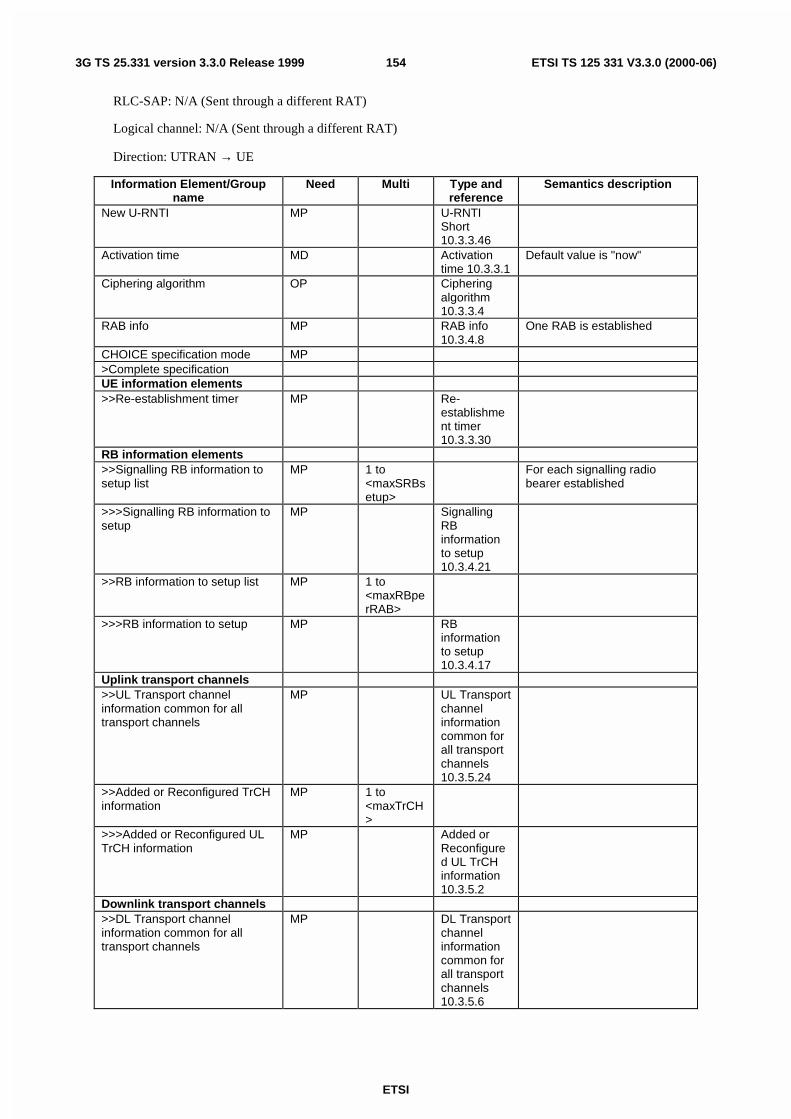
ETSI
ETSI TS 125 331 V3.3.0 (2000-06)1543G TS 25.331 version 3.3.0 Release 1999
RLC-SAP: N/A (Sent through a different RAT)
Logical channel: N/A (Sent through a different RAT)
Direction: UTRAN → UE
Information Element/Groupname
Need Multi Type andreference
Semantics description
New U-RNTI MP U-RNTIShort10.3.3.46
Activation time MD Activationtime 10.3.3.1
Default value is "now"
Ciphering algorithm OP Cipheringalgorithm10.3.3.4
RAB info MP RAB info10.3.4.8
One RAB is established
CHOICE specification mode MP>Complete specificationUE information elements>>Re-establishment timer MP Re-
establishment timer10.3.3.30
RB information elements>>Signalling RB information tosetup list
MP 1 to<maxSRBsetup>
For each signalling radiobearer established
>>>Signalling RB information tosetup
MP SignallingRBinformationto setup10.3.4.21
>>RB information to setup list MP 1 to<maxRBperRAB>
>>>RB information to setup MP RBinformationto setup10.3.4.17
Uplink transport channels>>UL Transport channelinformation common for alltransport channels
MP UL Transportchannelinformationcommon forall transportchannels10.3.5.24
>>Added or Reconfigured TrCHinformation
MP 1 to<maxTrCH>
>>>Added or Reconfigured ULTrCH information
MP Added orReconfigured UL TrCHinformation10.3.5.2
Downlink transport channels>>DL Transport channelinformation common for alltransport channels
MP DL Transportchannelinformationcommon forall transportchannels10.3.5.6

ETSI
ETSI TS 125 331 V3.3.0 (2000-06)1553G TS 25.331 version 3.3.0 Release 1999
>>Added or Reconfigured TrCHinformation
MP 1 to<maxTrCH>
>>>Added or Reconfigured DLTrCH information
MP Added orReconfigured DL TrCHinformation10.3.5.1
Uplink radio resources>>Uplink DPCH info MP Uplink
DPCH info10.3.6.76
Downlink radio resources>>CHOICE mode MP>>>FDD>>>>Downlink informationcommon for all radio links
MP Downlinkinformationcommon forall radio links10.3.6.20
>>>>Downlink PDSCHinformation
OP DownlinkPDSCHinformation10.3.6.26
>>>>CPCH SET Info OP CPCH SETInfo10.3.6.10
>>>TDD (no data)>>Downlink information perradio link
MP 1 to<maxRL>
>>>Downlink information foreach radio link
MP Downlinkinformationfor eachradio link10.3.6.23
>Preconfiguration>>Predefined configurationidentity
MP Predefinedconfigurationidentity10.3.4.5
>>Uplink DPCH info MP UplinkDPCH infoPost10.3.6.77
Downlink radio resources>>CHOICE mode>>>FDD>>>>Downlink informationcommon for all radio links
Downlinkinformationcommon forall radio linksPost10.3.6.21
>>>TDD (no data)>>Downlink information perradio link
MP 1 to<maxRL>
Send downlink information foreach radio link to be set-up.In TDD MaxRL is 1.
>>>Downlink information foreach radio link
MP Downlinkinformationfor eachradiolinkPost10.3.6.24
Frequency info MP Frequencyinfo10.3.6.30

ETSI
ETSI TS 125 331 V3.3.0 (2000-06)1563G TS 25.331 version 3.3.0 Release 1999
Maximum allowed UL TX power MP Maximumallowed ULTX power10.3.6.33
CHOICE mode MP>FDD (no data)>TDD>>Primary CCPCH Tx Power MP Primary
CCPCH TxPower10.3.6.50
10.2.11 HANDOVER TO UTRAN COMPLETE
This message is sent by the UE when a handover to UTRAN has been completed.
RLC-SAP: AM
Logical channel: DCCH
Direction: UE → UTRAN
Information Element/Groupname
Need Multi Type andreference
Semantics description
Message Type MP MessageType
START list CH 1 to<maxCNdomains>
START [TS 33.102] values forall CN domains. The IE ismandatory if it has not beentransferred prior to thehandover.
>CN domain identity MP CN domainidentity10.3.1.1
>START CH Hyper framenumber10.3.3.13
The IE is mandatory if it hasnot been transferred prior tothe handover
10.2.12 INITIAL DIRECT TRANSFER
This message is used to initiate a signalling connection or to establish a new signalling flow based on indication fromthe upper layers, and to transfer NAS messages.
RLC-SAP: AM
Logical channel: DCCH
Direction: UE -> UTRAN

ETSI
ETSI TS 125 331 V3.3.0 (2000-06)1573G TS 25.331 version 3.3.0 Release 1999
Information Element/Groupname
Need Multi Type andreference
Semantics description
Message Type MP MessageType
UE information elementsIntegrity check info CH Integrity
check info10.3.3.15
CN information elementsService Descriptor MP Service
Descriptor10.3.1.17
Flow Identifier MP FlowIdentifier10.3.1.4
Allocated by UE for aparticular flow
CN domain identity MP CN domainidentity10.3.1.1
NAS message MP NASmessage10.3.1.8
Measurement informationelementsMeasured results on RACH OP Measured
results onRACH10.3.7.70
10.2.13 INTER-SYSTEM HANDOVER COMMAND
This message is used for handover from UMTS to another system e.g. GSM. One or several messages from the othersystem can be included in the Inter-System message information element in this message. These messages arestructured and coded according to that systems specification.
RLC-SAP: AM
Logical channel: DCCH
Direction: UTRAN→UE
Information Element/Groupname
Need Multi Type andreference
Semantics description
Message Type MP MessageType
Integrity check info CH Integritycheck info10.3.3.15
Activation time MD Activationtime 10.3.3.1
Default value is "now"
RAB info OP RAB info10.3.4.8
Remaining radio accessbearer if any
Inter-System message MP Inter-Systemmessage10.3.8.6
10.2.14 INTER-SYSTEM HANDOVER FAILURE
This message is sent on the RRC connection used before the Inter-System Handover was executed. The messageindicates that the UE has failed to seize the new channel in the other system.
RLC-SAP: AM
Logical channel: DCCH

ETSI
ETSI TS 125 331 V3.3.0 (2000-06)1583G TS 25.331 version 3.3.0 Release 1999
Direction: UE→UTRAN
Information Element/Groupname
Need Multi Type andreference
Semantics description
Message Type MP MessageType
UE information elementsIntegrity check info CH Integrity
check info10.3.3.15
Other information elementsInter-System handover failure OP Inter-System
handoverfailure10.3.8.5
10.2.15 MEASUREMENT CONTROL
This message is sent by UTRAN to setup, modify or release a measurement in the UE.
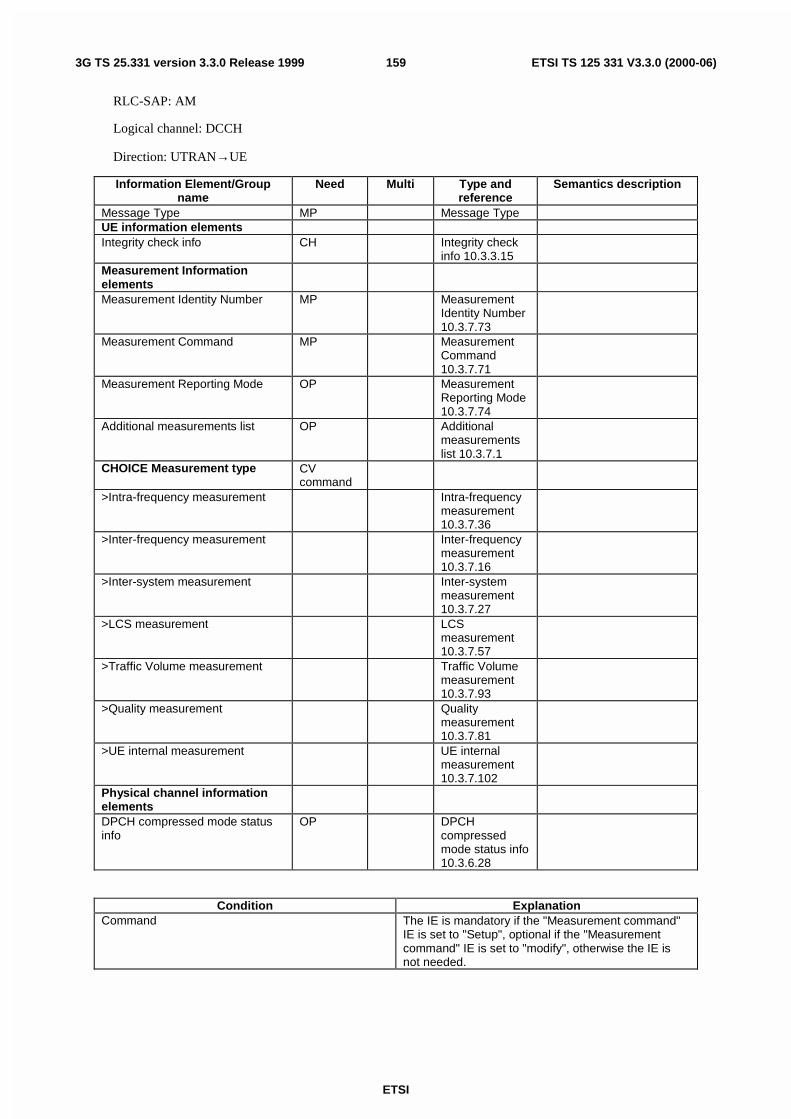
ETSI
ETSI TS 125 331 V3.3.0 (2000-06)1593G TS 25.331 version 3.3.0 Release 1999
RLC-SAP: AM
Logical channel: DCCH
Direction: UTRAN→UE
Information Element/Groupname
Need Multi Type andreference
Semantics description
Message Type MP Message TypeUE information elementsIntegrity check info CH Integrity check
info 10.3.3.15Measurement InformationelementsMeasurement Identity Number MP Measurement
Identity Number10.3.7.73
Measurement Command MP MeasurementCommand10.3.7.71
Measurement Reporting Mode OP MeasurementReporting Mode10.3.7.74
Additional measurements list OP Additionalmeasurementslist 10.3.7.1
CHOICE Measurement type CVcommand
>Intra-frequency measurement Intra-frequencymeasurement10.3.7.36
>Inter-frequency measurement Inter-frequencymeasurement10.3.7.16
>Inter-system measurement Inter-systemmeasurement10.3.7.27
>LCS measurement LCSmeasurement10.3.7.57
>Traffic Volume measurement Traffic Volumemeasurement10.3.7.93
>Quality measurement Qualitymeasurement10.3.7.81
>UE internal measurement UE internalmeasurement10.3.7.102
Physical channel informationelementsDPCH compressed mode statusinfo
OP DPCHcompressedmode status info10.3.6.28
Condition ExplanationCommand The IE is mandatory if the "Measurement command"
IE is set to "Setup", optional if the "Measurementcommand" IE is set to "modify", otherwise the IE isnot needed.

ETSI
ETSI TS 125 331 V3.3.0 (2000-06)1603G TS 25.331 version 3.3.0 Release 1999
10.2.16 MEASUREMENT CONTROL FAILURE
This message is sent by UE, if it can not initiate a measurement as instructed by UTRAN.
RLC-SAP: AM
Logical channel: DCCH
Direction: UE→UTRAN
Information Element/Groupname
Need Multi Type andreference
Semantics description
Message Type MP MessageType
UE information elementsIntegrity check info CH Integrity
check info10.3.3.15
Failure cause MP Failurecause anderrorinformation10.3.3.12
10.2.17 MEASUREMENT REPORT
This message is used by UE to transfer measurement results to the UTRAN.
RLC-SAP: AM or UM
Logical channel: DCCH
Direction: UE→UTRAN
Information Element/Groupname
Need Multi Type andreference
Semantics description
Message Type MP MessageType
UE information elementsIntegrity check info CH Integrity
check info10.3.3.15
Measurement InformationElementsMeasurement identity number MP Measuremen
t identitynumber10.3.7.73
Measured Results OP MeasuredResults10.3.7.69
Additional Measured results OP 1 to<maxAdditionalMeas>
>Measured Results MP MeasuredResults10.3.7.69
Event results OP Event results10.3.7.7

ETSI
ETSI TS 125 331 V3.3.0 (2000-06)1613G TS 25.331 version 3.3.0 Release 1999
10.2.18 PAGING TYPE 1
This message is used to send information on the paging channel. One or several UEs, in idle or connected mode, can bepaged in one message, which also can contain other information.
RLC-SAP: TM
Logical channel: PCCH
Direction: UTRAN → UE
Information Element/Groupname
Need Multi Type andreference
Semantics description
Message Type MP MessageType
UE Information elementsPaging record list OP 1 to
<maxPage1>
>Paging record MP Pagingrecord10.3.3.24
Other information elementsBCCH modification info OP BCCH
modificationinfo 10.3.8.1
If the encoded message does not fill a transport block, the RRC layer shall add padding according to subclause 12.1.
10.2.19 PAGING TYPE 2
This message is used to page an UE in connected mode, when using the DCCH for CN originated paging.
RLC-SAP: AM
Logical channel: DCCH
Direction: UTRAN → UE
Information Element/Groupname
Need Multi Type andreference
Semantics description
Message Type MP MessageType
UE information elementsIntegrity check info CH Integrity
check info10.3.3.15
Paging cause MP Pagingcause10.3.3.23
CN Information elementsCN domain identity MP CN domain
identity10.3.1.1
Paging Record Type Identifier MP PagingRecord TypeIdentifier10.3.1.10

ETSI
ETSI TS 125 331 V3.3.0 (2000-06)1623G TS 25.331 version 3.3.0 Release 1999
10.2.20 PHYSICAL CHANNEL RECONFIGURATION
This message is used by UTRAN to assign, replace or release a set of physical channels used by a UE.
RLC-SAP: AM or UM
Logical channel: DCCH
Direction: UTRAN → UE
Information Element/Groupname
Need Multi Type andreference
Semantics description
Message Type MP MessageType
UE Information ElementsIntegrity check info CH Integrity
check info10.3.3.15
Integrity protection mode info OP Integrityprotectionmode info10.3.3.18
Ciphering mode info OP Cipheringmode info10.3.3.5
Activation time MD Activationtime 10.3.3.1
Default value is "now"
New U-RNTI OP U-RNTI10.3.3.45
New C-RNTI OP C-RNTI10.3.3.8
DRX Indicator MP DRXIndicator10.3.3.10
UTRAN DRX cycle lengthcoefficient
MD UTRAN DRXcycle lengthcoefficient10.3.3.47
Default value is the existingvalue of UTRAN DRX cyclelength coefficient
CN Information ElementsCN Information info OP CN
Informationinfo 10.3.1.3
RB information elementsRB with PDCP information list OP 1 to
<maxRBallRABs>
This IE is needed for each RBhaving PDCP in the case oflossless SRNS relocation
>RB with PDCP information MP RB withPDCPinformation10.3.4.19
PhyCH information elementsFrequency info MD Frequency
info10.3.6.30
Default value is the existingvalue of frequency information
Uplink radio resourcesMaximum allowed UL TX power MD Maximum
allowed ULTX power10.3.6.33
Default value is the existingvalue of the maximum allowedUL TX power
CHOICE channel requirement OP At least one criticality=rejectspare value needed for futureextension
>Uplink DPCH info UplinkDPCH info10.3.6.76

ETSI
ETSI TS 125 331 V3.3.0 (2000-06)1633G TS 25.331 version 3.3.0 Release 1999
>PRACH Info (for RACH) PRACH Info(for RACH)10.3.6.44
Downlink radio resourcesCHOICE mode MP>FDD>>Downlink informationcommon for all radio links
OP Downlinkinformationcommon forall radio links10.3.6.20
>>Downlink PDSCH information OP DownlinkPDSCHinformation10.3.6.26
>>CPCH SET Info OP CPCH SETInfo10.3.6.10
> TDD (no data)Downlink information per radiolink list
OP 1 to<maxRL>
Send downlink information foreach radio link
>Downlink information for eachradio link
MP Downlinkinformationfor eachradio link10.3.6.23
10.2.21 PHYSICAL CHANNEL RECONFIGURATION COMPLETE
This message is sent from the UE when a physical channel reconfiguration has been done.
RLC-SAP: AM
Logical channel: DCCH
Direction: UE → UTRAN

ETSI
ETSI TS 125 331 V3.3.0 (2000-06)1643G TS 25.331 version 3.3.0 Release 1999
Information Element/Groupname
Need Multi Type andreference
Semantics description
Message Type MP MessageType
UE information elementsIntegrity check info CH Integrity
check info10.3.3.15
Uplink integrity protectionactivation info
OP Integrityprotectionactivationinfo10.3.3.16
CHOICE mode MP>FDD (no data)>TDD>>Uplink Timing Advance OP Uplink
TimingAdvance10.3.6.82
RB Information elementsRadio bearer uplink cipheringactivation time info
OP RBactivationtime info10.3.4.10
RB with PDCP information list OP 1 to<maxRBallRABs>
This IE is needed for each RBhaving PDCP in the case oflossless SRNS relocation
>RB with PDCP information MP RB withPDCPinformation10.3.4.19
10.2.22 PHYSICAL CHANNEL RECONFIGURATION FAILURE
This message is sent by UE if the configuration given by UTRAN is unacceptable or if the UE failed to assign, replaceor release a set of physical channel(s).
RLC-SAP: AM
Logical channel: DCCH
Direction: UE→UTRAN
Information Element/Groupname
Need Multi Type andreference
Semantics description
Message type MP Messagetype
UE information elementsIntegrity check info CH Integrity
check info10.3.3.15
Failure cause MP Failurecause anderrorinformation10.3.3.12
10.2.23 PHYSICAL SHARED CHANNEL ALLOCATION
NOTE: Only for TDD.

ETSI
ETSI TS 125 331 V3.3.0 (2000-06)1653G TS 25.331 version 3.3.0 Release 1999
This message is used by UTRAN to assign physical resources to USCH/DSCH transport channels in TDD, fortemporary usage by the UE.
RLC-SAP: TM or UM on SHCCH, UM on DCCH
Logical channel: SHCCH or DCCH
Direction: UTRAN → UE
Information Element/Groupname
Need Multi Type andreference
Semantics description
Message Type MP Messagetype
C-RNTI OP C-RNTI10.3.3.8
Uplink timing advance MD UplinkTimingAdvance10.3.6.82
Default value is the existingvalue for uplink timing advance
Allocation period info OP Allocationperiod info10.3.6.4
PUSCH capacity allocation info OP PUSCHCapacityAllocationinfo10.3.6.55
PDSCH info OP PDSCH info10.3.6.37
Timeslot list OP 1 tomaxTS
>Timeslot number MP Timeslotnumber10.3.6.72
Timeslot numbers, for whichthe UE shall report the timeslotISCP in PUSCH CAPACITYREQUEST message.

ETSI
ETSI TS 125 331 V3.3.0 (2000-06)1663G TS 25.331 version 3.3.0 Release 1999
10.2.24 PUSCH CAPACITY REQUEST
NOTE: Only for TDD.
This message is used by the UE for request of PUSCH resources to the UTRAN.
RLC-SAP: TM
Logical channel: SHCCH
Direction: UE → UTRAN
Information Element/Groupname
Need Multi Type andreference
Semantics description
Message Type MP MessageType
C-RNTI OP C-RNTI10.3.3.8
Traffic Volume MP TrafficVolume,measuredresults list10.3.7.92
Timeslot list OP 1 tomaxTS
>Timeslot number MP Timeslotnumber10.3.6.72
>Timeslot ISCP MPPrimary CCPCH RSCP OP

ETSI
ETSI TS 125 331 V3.3.0 (2000-06)1673G TS 25.331 version 3.3.0 Release 1999
10.2.25 RADIO BEARER RECONFIGURATION
This message is sent from UTRAN to reconfigure parameters related to a change of QoS. This procedure can alsochange the multiplexing of MAC, reconfigure transport channels and physical channels.
RLC-SAP: AM or UM
Logical channel: DCCH
Direction: UTRAN → UE
Information Element/Groupname
Need Multi Type andreference
Semantics description
Message Type MP MessageType
UE Information elementsIntegrity check info CH Integrity
check info10.3.3.15
Integrity protection mode info OP Integrityprotectionmode info10.3.3.18
Ciphering mode info OP Cipheringmode info10.3.3.5
Activation time MD Activationtime 10.3.3.1
Default value is "now"
New U-RNTI OP U-RNTI10.3.3.45
New C-RNTI OP C-RNTI10.3.3.8
DRX Indicator MP DRXIndicator10.3.3.10
UTRAN DRX cycle lengthcoefficient
MD UTRAN DRXcycle lengthcoefficient10.3.3.47
Default value is the existingvalue of UTRAN DRX cyclelength coefficient
CN information elementsCN Information info OP CN
Informationinfo 10.3.1.3
RB information elementsRB information to reconfigure list MP 1to
<maxRB>>RB information to reconfigure MP RB
informationtoreconfigure10.3.4.15
RB information to be affected list OP 1 to<maxRB>
>RB information to be affected MP RBinformationto beaffected10.3.4.14
TrCH Information ElementsUplink transport channels

ETSI
ETSI TS 125 331 V3.3.0 (2000-06)1683G TS 25.331 version 3.3.0 Release 1999
UL Transport channelinformation common for alltransport channels
OP UL Transportchannelinformationcommon forall transportchannels10.3.5.24
Deleted TrCH information list OP 1 to<maxTrCH>
> Deleted UL TrCH information MP Deleted ULTrCHinformation10.3.5.5
Added or Reconfigured TrCH information list
OP 1 to<maxTrCH>
>Added or Reconfigured ULTrCH information
MP Added orReconfigured UL TrCHinformation10.3.5.2
CHOICE mode OP>FDD>>CPCH set ID OP CPCH set ID
10.3.5.3>> Added or Reconfigured TrCH information for DRAC list
OP 1 to<maxTrCH>
>>>DRAC static information MP DRAC staticinformation10.3.5.7
>TDD (no data)Downlink transport channelsDL Transport channelinformation common for alltransport channels
OP DL Transportchannelinformationcommon forall transportchannels10.3.5.6
Deleted TrCH information list OP 1 to<maxTrCH>
>Deleted DL TrCH information MP Deleted DLTrCHinformation10.3.5.4
Added or Reconfigured TrCH information list
OP 1 to<maxTrCH>
>Added or Reconfigured DLTrCH information
MP Added orReconfigured DL TrCHinformation10.3.5.1
PhyCH information elementsFrequency info MD Frequency
info10.3.6.30
Default value is the existingvalue of frequency information
Uplink radio resourcesMaximum allowed UL TX power MD Maximum
allowed ULTX power10.3.6.33
Default value is the existingmaximum UL TX power
CHOICE channel requirement OP At least one spare choice(criticality = reject) required

ETSI
ETSI TS 125 331 V3.3.0 (2000-06)1693G TS 25.331 version 3.3.0 Release 1999
>Uplink DPCH info UplinkDPCH info10.3.6.76
>PRACH Info (for RACH) PRACH Info(for RACH)10.3.6.44
Downlink radio resourcesCHOICE mode MP>FDD>>Downlink informationcommon for all radio links
OP Downlinkinformationcommon forall radio links10.3.6.20
>>Downlink PDSCH information OP DownlinkPDSCHinformation10.3.6.26
>>CPCH SET Info OP CPCH SETInfo10.3.6.10
>TDD (no data)Downlink information per radiolink list
OP 1 to<maxRL>
>Downlink information for eachradio link
MP Downlinkinformationfor eachradio link10.3.6.23

ETSI
ETSI TS 125 331 V3.3.0 (2000-06)1703G TS 25.331 version 3.3.0 Release 1999
10.2.26 RADIO BEARER RECONFIGURATION COMPLETE
This message is sent from the UE when a RB and signalling link reconfiguration has been done.
RLC-SAP: AM
Logical channel: DCCH
Direction: UE → UTRAN
Information Element/Groupname
Need Multi Type andreference
Semantics description
Message Type MP MessageType
UE information elementsIntegrity check info CH Integrity
check info10.3.3.15
Uplink integrity protectionactivation info
OP Integrityprotectionactivationinfo10.3.3.16
CHOICE mode MP>FDD (no data)>TDD>>Uplink Timing Advance OP Uplink
TimingAdvance10.3.6.82
RB Information elementsRadio bearer uplink cipheringactivation time info
OP RBactivationtime info10.3.4.10
RB with PDCP information list OP 1 to<maxRBallRABs>
This IE is needed for each RBhaving PDCP in the case oflossless SRNS relocation
>RB with PDCP information MP RB withPDCPinformation10.3.4.19
10.2.27 RADIO BEARER RECONFIGURATION FAILURE
This message is sent by UE if the configuration given by UTRAN is unacceptable or if the UE failed to establish thephysical channel(s).

ETSI
ETSI TS 125 331 V3.3.0 (2000-06)1713G TS 25.331 version 3.3.0 Release 1999
RLC-SAP: AM
Logical channel: DCCH
Direction: UE→UTRAN
Information Element/Groupname
Need Multi Type andreference
Semantics description
Message Type MP MessageType
UE information elementsIntegrity check info CH Integrity
check info10.3.3.15
Failure cause MP Failurecause anderrorinformation10.3.3.12
RB information elementsRadio bearers for whichreconfiguration would havesucceeded
OP 1.to.<maxRB>
RB identity,10.3.4.13
10.2.28 RADIO BEARER RELEASE
This message is used by UTRAN to release a radio bearer. It can also include modifications to the configurations oftransport channels and/or physical channels.

ETSI
ETSI TS 125 331 V3.3.0 (2000-06)1723G TS 25.331 version 3.3.0 Release 1999
RLC-SAP: AM or UM
Logical channel: DCCH
Direction: UTRAN → UE
Information Element/Groupname
Need Multi Type andreference
Semantics description
Message Type MP MessageType
UE Information ElementsIntegrity check info CH Integrity
check info10.3.3.15
Integrity protection mode info OP Integrityprotectionmode info10.3.3.18
Ciphering mode info OP Cipheringmode info10.3.3.5
Activation time MD Activationtime 10.3.3.1
Default value is "now"
New U-RNTI OP U-RNTI10.3.3.45
New C-RNTI OP C-RNTI10.3.3.8
DRX Indicator MP DRXIndicator10.3.3.10
UTRAN DRX cycle lengthcoefficient
MD UTRAN DRXcycle lengthcoefficient10.3.3.47
Default value is the existingvalue of UTRAN DRX cyclelength coefficient
CN Information ElementsCN Information info OP CN
Informationinfo 10.3.1.3
RB Information ElementsRB information to release list MP 1 to
<maxRB>>RB information to release MP RB
informationto release10.3.4.16
RB information to be affected list OP 1 to<maxRB>
>RB information to be affected MP RBinformation
to beaffected
10.3.4.14TrCH Information ElementsUplink transport channelsUL Transport channelinformation common for alltransport channels
OP UL Transportchannel
informationcommon forall transport
channels10.3.5.24
Deleted TrCH information list OP 1 to<axTrCH>
>Deleted UL TrCH information MP Deleted ULTrCHinformation10.3.5.5

ETSI
ETSI TS 125 331 V3.3.0 (2000-06)1733G TS 25.331 version 3.3.0 Release 1999
Added or Reconfigured TrCH information list
OP 1 to<maxTrCH>
>Added or Reconfigured ULTrCH information
MP Added orReconfigured UL TrCHinformation10.3.5.2
CHOICE mode OP>FDD>>CPCH set ID OP CPCH set ID
10.3.5.3>> Added or Reconfigured TrCH information for DRAC list
OP 1 to<maxTrCH>
>>>DRAC static information MP DRAC staticinformation10.3.5.7
>TDD (no data)Downlink transport channelsDL Transport channelinformation common for alltransport channels
OP DL Transportchannelinformationcommon forall transportchannels10.3.5.6
Deleted TrCH information list OP 1 to<maxTrCH>
>Deleted DL TrCH information MP Deleted DLTrCH
information10.3.5.4
Added or Reconfigured TrCH information list
OP 1 to<maxTrCH>
>Added or Reconfigured DLTrCH information
MP Added orReconfigure
d DL TrCHinformation
10.3.5.1PhyCH information elementsFrequency info MD Frequency
info10.3.6.30
Default value is the existingvalue of frequency information
Uplink radio resourcesMaximum allowed UL TX power MD Maximum
allowed ULTX power10.3.6.33
Default value is the existingmaximum UL TX power
CHOICE channel requirement OP At least one spare choice(criticality = reject) required
>Uplink DPCH info UplinkDPCH info10.3.6.76
>PRACH Info (for RACH) PRACH Info(for RACH)10.3.6.44
Downlink radio resourcesCHOICE mode MP>FDD>>Downlink informationcommon for all radio links
OP Downlinkinformationcommon forall radio links
10.3.6.20
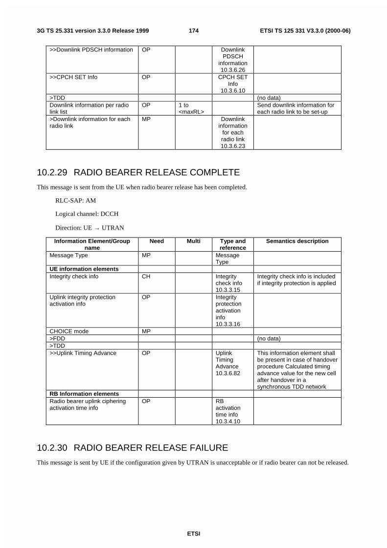
ETSI
ETSI TS 125 331 V3.3.0 (2000-06)1743G TS 25.331 version 3.3.0 Release 1999
>>Downlink PDSCH information OP DownlinkPDSCH
information10.3.6.26
>>CPCH SET Info OP CPCH SETInfo
10.3.6.10>TDD (no data)Downlink information per radiolink list
OP 1 to<maxRL>
Send downlink information foreach radio link to be set-up
>Downlink information for eachradio link
MP Downlinkinformation
for eachradio link10.3.6.23
10.2.29 RADIO BEARER RELEASE COMPLETE
This message is sent from the UE when radio bearer release has been completed.
RLC-SAP: AM
Logical channel: DCCH
Direction: UE → UTRAN
Information Element/Groupname
Need Multi Type andreference
Semantics description
Message Type MP MessageType
UE information elementsIntegrity check info CH Integrity
check info10.3.3.15
Integrity check info is includedif integrity protection is applied
Uplink integrity protectionactivation info
OP Integrityprotectionactivationinfo10.3.3.16
CHOICE mode MP>FDD (no data)>TDD>>Uplink Timing Advance OP Uplink
TimingAdvance10.3.6.82
This information element shallbe present in case of handoverprocedure Calculated timingadvance value for the new cellafter handover in asynchronous TDD network
RB Information elementsRadio bearer uplink cipheringactivation time info
OP RBactivationtime info10.3.4.10
10.2.30 RADIO BEARER RELEASE FAILURE
This message is sent by UE if the configuration given by UTRAN is unacceptable or if radio bearer can not be released.

ETSI
ETSI TS 125 331 V3.3.0 (2000-06)1753G TS 25.331 version 3.3.0 Release 1999
RLC-SAP: AM
Logical channel: DCCH
Direction: UE→UTRAN
Information Element/Groupname
Need Multi Type andreference
Semantics description
Message Type MP MessageType
UE information elementsIntegrity check info CH Integrity
check info10.3.3.15
Failure cause MP Failurecause anderrorinformation10.3.3.12
RB information elementsRadio bearers for whichreconfiguration would havesucceeded
OP 1.to.<maxRB>
RB identity,10.3.4.13
10.2.31 RADIO BEARER SETUP
This message is sent by UTRAN to the UE to establish new radio bearer(s). It can also include modifications to theconfigurations of transport channels and/or physical channels.

ETSI
ETSI TS 125 331 V3.3.0 (2000-06)1763G TS 25.331 version 3.3.0 Release 1999
RLC-SAP: AM or UM
Logical channel: DCCH
Direction: UTRAN → UE
Information Element/Groupname
Need Multi Type andreference
Semantics description
Message Type MP MessageType
UE Information ElementsIntegrity check info CH Integrity
check info10.3.3.15
Integrity protection mode info OP Integrityprotectionmode info10.3.3.18
Ciphering mode info OP Cipheringmode info10.3.3.5
Activation time MD Activationtime 10.3.3.1
Default value is "now"
New U-RNTI OP U-RNTI10.3.3.45
New C-RNTI OP C-RNTI10.3.3.8
DRX Indicator MP DRXIndicator10.3.3.10
UTRAN DRX cycle lengthcoefficient
MD UTRAN DRXcycle lengthcoefficient10.3.3.47
Default value is the existingvalue of UTRAN DRX cyclelength coefficient
CN Information ElementsCN Information info OP CN
Informationinfo 10.3.1.3
RB Information ElementsSignalling RB information tosetup list
OP 1 to<maxSRBsetup>
For each signalling radiobearer established
>Signalling RB information tosetup
MP SignallingRBinformationto setup10.3.4.21
RAB information to setup list MP 1 to<maxRABsetup>
For each RAB established
>RAB information for setup MP RABinformationfor setup10.3.4.9
RB information to be affected list OP 1 to<maxRB>
>RB information to be affected MP RBinformationto beaffected10.3.4.14
TrCH Information ElementsUplink transport channels

ETSI
ETSI TS 125 331 V3.3.0 (2000-06)1773G TS 25.331 version 3.3.0 Release 1999
UL Transport channelinformation common for alltransport channels
OP UL Transportchannelinformationcommon forall transportchannels10.3.5.24
Deleted TrCH information list OP 1 to<maxTrCH>
>Deleted UL TrCH information MP Deleted ULTrCHinformation10.3.5.5
Added or Reconfigured TrCH information list
OP 1 to<maxTrCH>
>Added or Reconfigured ULTrCH information
MP Added orReconfigured UL TrCHinformation10.3.5.2
CHOICE mode OP>FDD>>CPCH set ID OP CPCH set ID
10.3.5.3>> Added or Reconfigured TrCH information for DRAC list
OP 1 to<maxTrCH>
>>>DRAC static information MP DRAC staticinformation10.3.5.7
>TDD (no data)Downlink transport channelsDL Transport channelinformation common for alltransport channels
OP DL Transportchannelinformationcommon forall transportchannels10.3.5.6
Deleted TrCH information list OP 1 to<maxTrCH>
>Deleted DL TrCH information MP Deleted DLTrCHinformation10.3.5.4
Added or Reconfigured TrCH information list
OP 1 to<maxTrCH>
>Added or Reconfigured DLTrCH information
MP Added orReconfigured DL TrCHinformation10.3.5.1
PhyCH information elementsFrequency info MD Frequency
info10.3.6.30
Default value is the existingvalue of frequency information
Uplink radio resourcesMaximum allowed UL TX power MD Maximum
allowed ULTX power10.3.6.33
Default value is the existingmaximum UL TX power
CHOICE channel requirement OP At least one spare choice(criticality = reject) required

ETSI
ETSI TS 125 331 V3.3.0 (2000-06)1783G TS 25.331 version 3.3.0 Release 1999
>Uplink DPCH info UplinkDPCH info10.3.6.76
>PRACH Info (for RACH) PRACH Info(for RACH)10.3.6.44
Downlink radio resourcesCHOICE mode MP>FDD>>Downlink informationcommon for all radio links
OP Downlinkinformationcommon forall radiolinks10.3.6.20
>>Downlink PDSCH information OP DownlinkPDSCHinformation10.3.6.26
>>CPCH SET Info OP CPCH SETInfo10.3.6.10
>TDD (no data)Downlink information per radiolink list
OP 1 to<maxRL>
Send downlink information foreach radio link
>Downlink information for eachradio link
MP Downlinkinformationfor eachradio link10.3.6.23
10.2.32 RADIO BEARER SETUP COMPLETE
This message is sent by UE to confirm the establishment of the radio bearer.

ETSI
ETSI TS 125 331 V3.3.0 (2000-06)1793G TS 25.331 version 3.3.0 Release 1999
RLC-SAP: AM
Logical channel: DCCH
Direction: UE → UTRAN
Information Element/Groupname
Need Multi Type andreference
Semantics description
Message Type MP MessageType
UE information elementsIntegrity check info CH Integrity
check info10.3.3.15
Uplink integrity protectionactivation info
OP Integrityprotectionactivationinfo10.3.3.16
CHOICE mode OP>FDD (no data)>TDD>>Uplink Timing Advance OP Uplink
TimingAdvance10.3.6.82
This information element shallbe present in case of handoverprocedure. Calculated timingadvance value for the new cellafter handover in asynchronous TDD network
Hyper frame number OP Hyper framenumber10.3.3.13
This information element is notneeded for transparent modeRBs
RB Information elementsRadio bearer uplink cipheringactivation time info
OP RBactivationtime info10.3.4.10
10.2.33 RADIO BEARER SETUP FAILURE
This message is sent by UE, if it does not support the configuration given by UTRAN.
RLC-SAP: AM
Logical channel: DCCH
Direction: UE→UTRAN
Information Element/Groupname
Need Multi Type andreference
Semantics description
Message Type MP MessageType
UE information elementsIntegrity check info CH Integrity
check info10.3.3.15
Failure cause MP Failurecause anderrorinformation10.3.3.12
RB information elementsRadio bearers for whichreconfiguration would havesucceeded
OP 1.to.<maxRB>
RB identity,10.3.4.13

ETSI
ETSI TS 125 331 V3.3.0 (2000-06)1803G TS 25.331 version 3.3.0 Release 1999
10.2.34 RNTI REALLOCATION
This message is used by UTRAN to allocate a new RNTI to a UE.
RLC-SAP: AM or UM
Logical channel: DCCH
Direction: UTRAN→UE
Information Element/Groupname
Need Multi Type andreference
Semantics description
Message Type MP MessageType
UE Information ElementsIntegrity check info CH Integrity
check info10.3.3.15
Integrity protection mode info OP Integrityprotectionmode info10.3.3.18
Ciphering mode info OP Cipheringmode info10.3.3.5
New U-RNTI OP U-RNTI10.3.3.45
New C-RNTI OP C-RNTI10.3.3.8
DRX Indicator MP DRXIndicator10.3.3.10
UTRAN DRX cycle lengthcoefficient
MD UTRAN DRXcycle lengthcoefficient10.3.3.47
Default value is the existingvalue of UTRAN DRX cyclelength coefficient
CN Information ElementsCN Information info OP CN
Informationinfo 10.3.1.3
RB Information elementsRB with PDCP information list OP 1 to
<maxRBallRABs>
This IE is needed for each RBhaving PDCP in the case oflossless SRNS relocation
>RB with PDCP information MP RB withPDCPinformation10.3.4.19
10.2.35 RNTI REALLOCATION COMPLETE
This message is used to confirm the new RNTI information for the UE.
RLC-SAP: AM
Logical channel: DCCH
Direction: UE→UTRAN

ETSI
ETSI TS 125 331 V3.3.0 (2000-06)1813G TS 25.331 version 3.3.0 Release 1999
Information Element/Groupname
Need Multi Type andreference
Semantics description
Message Type MP MessageType
UE information elementsIntegrity check info CH Integrity
check info10.3.3.15
Uplink integrity protectionactivation info
OP Integrityprotectionactivationinfo10.3.3.16
RB Information elementsRadio bearer uplink cipheringactivation time info
OP RBactivationtime info10.3.4.10
RB with PDCP information list OP 1 to<maxRBallRABs>
This IE is needed for each RBhaving PDCP in the case oflossless SRNS relocation
>RB with PDCP information MP RB withPDCPinformation10.3.4.19
10.2.36 RNTI REALLOCATION FAILURE
This message is sent to indicate a failure to act on a received RNTI REALLOCATION message.
RLC-SAP: AM
Logical channel: DCCH
Direction: UE→UTRAN
Information Element/Groupname
Need Multi Type andreference
Semantics description
Message Type MP MessageType
UE information elementsIntegrity check info CH Integrity
check info10.3.3.15
Failure cause MP Failurecause anderrorinformation10.3.3.12
10.2.37 RRC CONNECTION RE-ESTABLISHMENT
This message is sent by UTRAN in order to re-establish an RRC connection.

ETSI
ETSI TS 125 331 V3.3.0 (2000-06)1823G TS 25.331 version 3.3.0 Release 1999
RLC-SAP: UM
Logical channel: CCCH, DCCH
Direction: UTRAN → UE
Information Element/Groupname
Need Multi Type andreference
Semantics description
Message Type MP MessageType
UE Information ElementsU-RNTI CV-CCCH U-RNTI
10.3.3.45Integrity check info CH Integrity
check info10.3.3.15
Integrity protection mode info OP Integrityprotectionmode info10.3.3.18
Ciphering mode info OP Cipheringmode info10.3.3.5
Activation time MD Activationtime 10.3.3.1
Default value is "now"
New U-RNTI OP U-RNTI10.3.3.45
New C-RNTI OP C-RNTI10.3.3.8
DRX Indicator MP DRXIndicator10.3.3.10
UTRAN DRX cycle lengthcoefficient
MD UTRAN DRXcycle lengthcoefficient10.3.3.47
Default value is the existingvalue of UTRAN DRX cyclelength coefficient
RLC reset indicator (for C-plane) MP RLC resetindicator10.3.3.35
RLC reset indicator (for U-plane) MP RLC resetindicator10.3.3.35
CN Information ElementsCN Information info OP CN
Informationinfo 10.3.1.3
RB Information ElementsSignalling RB information tosetup list
OP 1 to<maxSRBsetup>
For each signalling radiobearer established
>Signalling RB information tosetup
MP SignallingRB
informationto setup
10.3.4.21RAB information for setup list OP 1 to
<maxRABsetup>
For each RAB established
>RAB information for setup MP RABinformationfor setup10.3.4.9
RB information to release list OP 1 to<maxRB>

ETSI
ETSI TS 125 331 V3.3.0 (2000-06)1833G TS 25.331 version 3.3.0 Release 1999
>RB information to release MP RBinformationto release10.3.4.16
RB information to reconfigure list OP 1 to<maxRB>
>RB information to reconfigure MP RBinformation
toreconfigure10.3.4.15
RB information to be affected list OP 1 to<maxRB>
>RB information to be affected MP RBinformation
to beaffected
10.3.4.14TrCH Information ElementsUplink transport channelsUL Transport channelinformation common for alltransport channels
OP UL Transportchannel
informationcommon forall transport
channels10.3.5.24
Deleted TrCH information list OP 1 to<maxTrCH>
>Deleted UL TrCH information MP Deleted ULTrCH
information10.3.5.5
Added or Reconfigured TrCH information list
OP 1 to<maxTrCH>
>Added or Reconfigured ULTrCH information
MP Added orReconfigure
d UL TrCHinformation
10.3.5.2CHOICE mode OP>FDD>>CPCH set ID OP CPCH set ID
10.3.5.3>> Added or Reconfigured TrCH information for DRAC list
OP 1 to<maxTrCH>
>>>DRAC static information MP DRAC staticinformation
10.3.5.7>TDD (no data)Downlink transport channelsDL Transport channelinformation common for alltransport channels
OP DL Transportchannelinformationcommon forall transportchannels10.3.5.6
Deleted TrCH information list OP 1 to<maxTrCH>

ETSI
ETSI TS 125 331 V3.3.0 (2000-06)1843G TS 25.331 version 3.3.0 Release 1999
>Deleted DL TrCH information MP Deleted DLTrCH
information10.3.5.4
Added or Reconfigured TrCH information list
OP 1 to<maxTrCH>
>Added or Reconfigured DLTrCH information
MP Added orReconfigure
d DL TrCHinformation
10.3.5.1PhyCH information elementsFrequency info MD Frequency
info10.3.6.30
Default value is the existingvalue of frequency information
Uplink radio resourcesMaximum allowed UL TX power MD Maximum
allowed ULTX power10.3.6.33
Default value is the existingmaximum UL TX power
CHOICE channel requirement OP At least one spare choice(criticality = reject) required
>Uplink DPCH info UplinkDPCH info10.3.6.76.
>PRACH Info (for RACH) PRACH Info(for RACH)10.3.6.44
Downlink radio resourcesCHOICE mode>FDD>>Downlink informationcommon for all radio links
OP Downlinkinformationcommon forall radio links
10.3.6.20>>Downlink PDSCH information OP Downlink
PDSCHinformation10.3.6.26
>>CPCH SET Info OP CPCH SETInfo
10.3.6.10>TDD (no data)Downlink information per radiolink list
OP 1 to<maxRL>
Send downlink information foreach radio link to be set-up
>Downlink information for eachradio link
MP Downlinkinformation
for eachradio link10.3.6.23
Condition ExplanationCCCH This IE is only sent when CCCH is used
10.2.38 RRC CONNECTION RE-ESTABLISHMENT COMPLETE
This message is used by UE to confirm the re-establishment of an RRC connection.
RLC-SAP: AM
Logical channel: DCCH

ETSI
ETSI TS 125 331 V3.3.0 (2000-06)1853G TS 25.331 version 3.3.0 Release 1999
Direction: UE → UTRAN
Information Element/Groupname
Need Multi Type andreference
Semantics description
Message Type MP MessageType
UE information elementsIntegrity check info CH Integrity
check info10.3.3.15
Uplink integrity protectionactivation info
OP Integrityprotectionactivationinfo10.3.3.16
CHOICE mode OP>FDD (no data)>TDD>>Uplink Timing Advance OP Uplink
TimingAdvance10.3.6.82
This information element shallbe present in case of handoverprocedure. Calculated timingadvance value for the new cellafter handover in asynchronous TDD network
Hyperframe number MP Hyper FrameNumber10.3.3.13
RB Information elementsRadio bearer uplink cipheringactivation time info
OP RBactivationtime info10.3.4.10
RB with PDCP information list OP 1 to<maxRBallRABs>
This IE is needed for each RBhaving PDCP in the case oflossless SRNS relocation
>RB with PDCP information MP RB withPDCPinformation10.3.4.19
10.2.39 RRC CONNECTION RE-ESTABLISHMENT REQUEST
This message is used by UE to request for the re-establishment of an RRC connection.
RLC-SAP: TM
Logical channel: CCCH
Direction: UE → UTRAN

ETSI
ETSI TS 125 331 V3.3.0 (2000-06)1863G TS 25.331 version 3.3.0 Release 1999
Information Element/Groupname
Need Multi Type andreference
Semantics description
Message Type MP MessageType
UE information elementsU-RNTI MP U-RNTI
10.3.3.45Integrity check info CH Integrity
check info10.3.3.15
Hyper frame number MP Hyper framenumber10.3.3.13
AM_RLC error indication(for C-plane)
MP Boolean TRUE indicates AM_RLCunrecoverable error occurredon c-plane in the UE
AM_RLC error indication(for U-plane)
MP Boolean TRUE indicates AM_RLCunrecoverable error occurredon u-plane in the UE
Protocol error indicator MD Protocolerrorindicator10.3.3.28
Default value is FALSE
Measurement informationelementsMeasured results on RACH OP Measured
results onRACH10.3.7.70
Other information elementsProtocol error information CV-ProtErr Protocol
errorinformation10.3.8.10
Condition ExplanationProtErr If the IE "Protocol error indicator" has the value
"TRUE"
10.2.40 RRC CONNECTION REJECT
The network transmits this message when the requested RRC connection cannot be accepted.
RLC-SAP: UM
Logical channel: CCCH
Direction: UTRAN → UE

ETSI
ETSI TS 125 331 V3.3.0 (2000-06)1873G TS 25.331 version 3.3.0 Release 1999
Information Element/Groupname
Need Multi Type andreference
Semantics description
Message Type MP MessageType
UE information elementsInitial UE identity MP Initial UE
identity10.3.3.14
Rejection cause MP Rejectioncause10.3.3.31
Wait time MP Wait time10.3.3.48
Redirection info OP Redirectioninfo10.3.3.29
10.2.41 RRC CONNECTION RELEASE
This message is sent by UTRAN to release the RRC connection. The message also releases the signalling connectionand all radio bearers between the UE and UTRAN.
RLC-SAP: UM or TM
Logical channel: CCCH orDCCH
Direction: UTRAN→UE
Information Element/Groupname
Need Multi Type andreference
Semantics description
Message Type MP MessageType
UE information elementsU-RNTI CV-CCCH U-RNTI
10.3.3.45Integrity check info CH Integrity
check info10.3.3.15
Integrity check info is includedif integrity protection is applied
Number of RRC MessageTransmissions
CHCell_DCH
Number ofRRCMessageTransmissions 10.3.3.22
Release cause MP Releasecause10.3.3.32
Condition ExplanationCCCH This IE is only sent when CCCH is used.Cell_DCH This IE is present when UE is in CELL_DCH state.
10.2.42 RRC CONNECTION RELEASE COMPLETE
This message is sent by UE to confirm that the RRC connection has been released.

ETSI
ETSI TS 125 331 V3.3.0 (2000-06)1883G TS 25.331 version 3.3.0 Release 1999
RLC-SAP: AM or UM or TM
Logical channel: CCCH or DCCH
Direction: UE → UTRAN
Information Element/Groupname
Need Multi Type andreference
Semantics description
Message Type MP MessageType
UE information elementsU-RNTI CV-CCCH U-RNTI
10.3.3.45Integrity check info CH Integrity
check info10.3.3.15
Condition ExplanationCCCH This IE is only sent when CCCH is used.
10.2.43 RRC CONNECTION REQUEST
RRC Connection Request is the first message transmitted by the UE when setting up an RRC Connection to thenetwork.
RLC-SAP: TM
Logical channel: CCCH
Direction: UE → UTRAN
Information Element/Groupname
Need Multi Type andreference
Semantics description
Message Type MP MessageType
UE information elementsInitial UE identity MP Initial UE
identity10.3.3.14
Establishment cause MP Establishment cause10.3.3.11
Protocol error indicator MD Protocolerrorindicator10.3.3.28
Default value is FALSE
Measurement informationelementsMeasured results on RACH OP Measured
results onRACH10.3.7.70
If the encoded message does not fill a transport block, the RRC layer shall insert padding according to subclause 12.1.

ETSI
ETSI TS 125 331 V3.3.0 (2000-06)1893G TS 25.331 version 3.3.0 Release 1999
10.2.44 RRC CONNECTION SETUP
This message is used by the network to accept the establishment of an RRC connection for an UE, including assignmentof signalling link information, transport channel information and optionally physical channel information.
RLC-SAP: UM
Logical channel: CCCH
Direction: UTRAN → UE
Information Element/Groupname
Need Multi Type andreference
Semantics description
Message Type MP MessageType
UE Information ElementsInitial UE identity MP Initial UE
identity10.3.3.14
Activation time MD Activationtime 10.3.3.1
Default value is "now"
New U-RNTI MP U-RNTI10.3.3.45
New C-RNTI OP C-RNTI10.3.3.8
UTRAN DRX cycle lengthcoefficient
MP UTRAN DRXcycle lengthcoefficient10.3.3.47
Capability update requirement MD Capabilityupdaterequirement10.3.3.2
Default value is defined insubclause 10.3.3.3
RB Information ElementsSignalling RB information tosetup list
MP 4 to 5 Information for signalling radiobearers, in the order RB 0 upto 4.
>Signalling RB information tosetup
MP SignallingRBinformationto setup10.3.4.21
TrCH Information ElementsUplink transport channelsUL Transport channelinformation common for alltransport channels
OP UL Transportchannelinformationcommon forall transportchannels10.3.5.24
Added or Reconfigured TrCH information list
MP 1 to<maxTrCH>
>Added or Reconfigured ULTrCH information
MP Added orReconfigured UL TrCHinformation10.3.5.2
Downlink transport channelsDL Transport channelinformation common for alltransport channels
OP DL Transportchannelinformationcommon forall transportchannels10.3.5.6

ETSI
ETSI TS 125 331 V3.3.0 (2000-06)1903G TS 25.331 version 3.3.0 Release 1999
Added or Reconfigured TrCH information list
MP 1 to<maxTrCH>
>Added or Reconfigured DLTrCH information
MP Added orReconfigured DL TrCHinformation10.3.5.1
PhyCH information elementsFrequency info MD Frequency
info10.3.6.30
Default value is the existingvalue of frequency information
Uplink radio resourcesMaximum allowed UL TX power MD Maximum
allowed ULTX power10.3.6.33
Default value is the existingmaximum UL TX power
CHOICE channel requirement OP At least one spare choice(criticality = reject) required
>Uplink DPCH info UplinkDPCH info10.3.6.76
>PRACH Info (for RACH) PRACH Info(for RACH)10.3.6.44
Downlink radio resourcesCHOICE mode MP>FDD>>Downlink informationcommon for all radio links
OP Downlinkinformationcommon forall radio links10.3.6.20
>TDD (no data)Downlink information per radiolink list
OP 1 to<MaxRL>
Send downlink information foreach radio link to be set-up
>Downlink information for eachradio link
MP Downlinkinformation
for eachradio link10.3.6.23
10.2.45 RRC CONNECTION SETUP COMPLETE
This message confirms the establishment of the RRC Connection by the UE.
RLC-SAP: AM
Logical channel: DCCH
Direction: UE → UTRAN

ETSI
ETSI TS 125 331 V3.3.0 (2000-06)1913G TS 25.331 version 3.3.0 Release 1999
Information Element/Groupname
Need Multi Type andreference
Semantics description
Message Type MP MessageType
START list MP 1 to<maxCNdomains>
START [TS 33.102] values forall CN domains.
>CN domain identity MP CN domainidentity10.3.1.1
>START MP Hyper framenumber10.3.3.13
START value to be used inthis CN domain.
UE information elementsUE radio access capability MP UE radio
accesscapability10.3.3.40
UE system specific capability OP Inter-systemmessage10.3.8.6
10.2.46 RRC STATUS
This message is sent to indicate a protocol error.
RLC-SAP: AM
Logical channel: DCCH
Direction: UE→UTRAN
Information Element/Groupname
Need Multi Type andreference
Semantics description
Message Type MP MessageType
UE information elementsIntegrity check info CH Integrity
check info10.3.3.15
Integrity check info is includedif integrity protection is applied
Other information elementsProtocol error information MP Protocol
errorinformation10.3.8.10
10.2.47 SECURITY MODE COMMAND
This message is sent by UTRAN to start or reconfigure ciphering and/or integrity protection parameters.

ETSI
ETSI TS 125 331 V3.3.0 (2000-06)1923G TS 25.331 version 3.3.0 Release 1999
RLC-SAP: AM
Logical channel: DCCH
Direction: UTRAN to UE
Information Element/Groupname
Need Multi Type andreference
Semantics description
Message Type MP MessageType
UE information elementsIntegrity check info CH Integrity
check info10.3.3.15
Integrity check info is includedif integrity protection is applied
Security capability MP Securitycapability10.3.3.36
Ciphering mode info OP Cipheringmode info10.3.3.5
Only present if ciphering shallbe controlled
Integrity protection mode info OP Integrityprotectionmodeinfo10.3.3.18
Only present if integrityprotection shall be controlled
CN Information elementsCN domain identity MP CN domain
identity10.3.1.1
Indicates which cipher andintegrity protection keys are isapplicable
10.2.48 SECURITY MODE COMPLETE
This message is sent by UE to confirm the reconfiguration of ciphering and/or integrity protection.
RLC-SAP: AM
Logical channel: DCCH
Direction: UE to UTRAN
Information Element/Groupname
Need Multi Type andreference
Semantics description
Message Type MP MessageType
UE information elementsIntegrity check info CH Integrity
check info10.3.3.15
Integrity check info is includedif integrity protection is applied
Uplink integrity protectionactivation info
OP Integrityprotectionactivationinfo10.3.3.16
RB Information elementsRadio bearer uplink cipheringactivation time info
OP RBactivationtime info10.3.4.10
10.2.49 SECURITY MODE FAILURE
This message is sent to indicate a failure to act on a received SECURITY MODE CONTROL message.

ETSI
ETSI TS 125 331 V3.3.0 (2000-06)1933G TS 25.331 version 3.3.0 Release 1999
RLC-SAP: AM
Logical channel: DCCH
Direction: UE→UTRAN
Information Element/Groupname
Need Multi Type andreference
Semantics description
Message Type MP MessageType
UE information elementsIntegrity check info CH Integrity
check info10.3.3.15
Failure cause MP Failurecause anderrorinformation10.3.3.12
10.2.50 SIGNALLING CONNECTION RELEASE
This message is used to notify the UE that one of its ongoing signalling connections to a CN domain has been released.
RLC-SAP: AM
Logical channel: DCCH
Direction: UTRAN→UE
Information Element/Groupname
Need Multi Type andreference
Semantics description
Message Type MP MessageType
UE information elementsIntegrity check info CH Integrity
check info10.3.3.15
Integrity check info is includedif integrity protection is applied
CN information elementsSignalling Flow relatedinformation list
MP 1 to<maxSignallingFlow>
Flow identifier to be providedfor each signalling flow to bereleased.
>Flow Identifier MP FlowIdentifier10.3.1.4
Multi Bound ExplanationMaxFlowId Maximum number of flow identifiers
10.2.51 SIGNALLING CONNECTION RELEASE REQUEST
This message is used by the UE to request for the release of one or more signalling connections to a CN domain.

ETSI
ETSI TS 125 331 V3.3.0 (2000-06)1943G TS 25.331 version 3.3.0 Release 1999
RLC-SAP: AM
Logical channel: DCCH
Direction: UE→UTRAN
Information Element/Groupname
Need Multi IE type andreference
Semantics description
Message Type MP Messagetype
CN information elementsSignalling Flow relatedinformation
1 to<maxFlowID>
Flow identifier to be providedfor each signalling flow to bereleased.
>Flow Identifier MP FlowIdentifier10.3.1.4
Allocated by UE for aparticular session
Multi Bound ExplanationMaxFlowId Maximum number of flow identifiers

ETSI
ETSI TS 125 331 V3.3.0 (2000-06)1953G TS 25.331 version 3.3.0 Release 1999
10.2.52 SYSTEM INFORMATION
Information Element/Groupname
Need Multi Type andreference
Semantics description
Message type OP Messagetype
The message type ismandatory on the FACH, andabsent on the BCH
SFNprime CVchannel
Integer(0..4094 by step of2)
SFN=SFNprime (for first 10msframe of 20ms TTI),SFN=SFNprime+1 (for last10ms frame of 20ms TTI)
CHOICE Segment combination MP>Combination 1 (no data)>Combination 2>>First Segment MP First
Segment,10.2.52.1
>Combination 3>>Subsequent Segment MP Subsequent
Segment,10.2.52.3
>Combination 4>>Last segment MP Last
segment,10.2.52.4
>Combination 5>>Last segment MP Last
Segment10.2.52.4
>>First Segment MP FirstSegment(short),10.2.52.2
>Combination 6>>Last Segment MP Last
Segment,10.2.52.4
>>Complete list 1 tomaxSIBsegm
Note 1
>>>Complete CompleteSIB,10.2.52.5
>Combination 7>>Last Segment MP Last
Segment,10.2.52.4
>>Complete list MP 1..16 Note 1>>>Complete MP Complete
SIB,10.2.52.5
>>First Segment MP FirstSegment(short),10.2.52.2
>Combination 8>>Complete list MP 1 to
maxSIBsegm
Note 1
>>>Complete MP CompleteSIB,10.2.52.5
>Combination 9>>Complete list MP 1..16 Note 1

ETSI
ETSI TS 125 331 V3.3.0 (2000-06)1963G TS 25.331 version 3.3.0 Release 1999
>>>Complete MP CompleteSIB,10.2.52.5
>>First Segment MP FirstSegment(short),10.2.52.2
If the encoded message does not fill a transport block, the RRC layer shall insert padding according to subclause 12.1.Padding is needed e.g. if the remaining space is insufficient to start a new First Segment (which requires several bits forSIB type, SEG_COUNT and SIB data).
NOTE 1: If Combination 6 - 9 contains a Master information block Master information shall be located as the firstIE in the list.
10.2.52.1 First Segment
This segment type is used to transfer the first segment of a segmented system information block. The IE is used whenthe first segment fills the entire transport block (Combination 1).
Information Element/Groupname
Need Multi Type andreference
Semantics description
Other information elementsSIB type MP SIB Type,
10.3.8.17SEG_COUNT MP SEG
COUNT,10.3.8.13
SIB data fixed MP SIB datafixed,10.3.8.15
10.2.52.2 First Segment (short)
This segment type is used to transfer the first segment of a segmented system information block. The IE is used whenthe first segment is concatenated after other segments in a transport block (Combination 5, 7 and 9).
Information Element/Groupname
Need Multi Type andreference
Semantics description
Other information elementsSIB type MP SIB Type,
10.3.8.17SEG_COUNT MP SEG
COUNT,10.3.8.13
SIB data variable MP SIB datavariable,10.3.8.16
10.2.52.3 Subsequent Segment
This segment type is used to transfer a subsequent segment of a segmented system information block.

ETSI
ETSI TS 125 331 V3.3.0 (2000-06)1973G TS 25.331 version 3.3.0 Release 1999
Information Element/Groupname
Need Multi Type andreference
Semantics description
Other information elementsSIB type MP SIB Type,
10.3.8.17Segment index MP Segment
Index,10.3.8.14
SIB data fixed MP SIB datafixed,10.3.8.15
10.2.52.4 Last Segment
This segment type is used to transfer the last segment of a segmented system information block.
Information Element/Groupname
Need Multi Type andreference
Semantics description
Other information elementsSIB type MP SIB Type,
10.3.8.17Segment index MP Segment
Index,10.3.8.14
SIB data variable MP SIB datavariable,10.3.8.15
10.2.52.5 Complete SIB
This segment type is used to transfer a non-segmented system information block.
Information Element/Groupname
Need Multi Type andreference
Semantics description
Other information elementsSIB type MP SIB Type,
10.3.8.17SIB data variable MP data,
10.2.52.6SIB datavariable,10.3.8.16
10.2.52.6 System Information Blocks
The IE "SIB data" within the IEs, "First Segment", "Subsequent or last Segment" and "Complete SIB" contains eithercomplete system information block or a segment of a system information block. The actual system information blocksare defined in the following clauses.

ETSI
ETSI TS 125 331 V3.3.0 (2000-06)1983G TS 25.331 version 3.3.0 Release 1999
10.2.52.6.1 Master Information Block
Information Element/Groupname
Need Multi Type andreference
Semantics description
Other information elementsMIB Value tag MP MIB Value
tag 10.3.8.7CN information elementsSupported PLMN types MP PLMN Type
10.3.1.12PLMN Identity CV GSM PLMN
Identity10.3.1.11
ANSI-41 information elementsANSI-41 Core NetworkInformation
CV ANSI-41
ANSI-41CoreNetworkInformation10.3.9.1
References to other systeminformation blocks
MP Referencesto othersysteminformationblocks10.3.8.11
Condition ExplanationGSM The IE is mandatory if the IE "Supported PLMN
Types" is set to 'GSM-MAP' or 'GSM-MAP AND ANSI-41', and not needed otherwise
ANSI-41 The IE is mandatory if the IE "Supported PLMNTypes" is set to 'ANSI-41' or 'GSM-MAP AND ANSI-41', and not needed otherwise

ETSI
ETSI TS 125 331 V3.3.0 (2000-06)1993G TS 25.331 version 3.3.0 Release 1999
10.2.52.6.2 System Information Block type 1
The system information block type 1 contains NAS system information as well as UE timers and counters to be used inidle mode and in CELL_DCH.
Information Element/Groupname
Need Multi Type andreference
Semantics description
References to other systeminformation blocks
OP Referencesto othersysteminformationblocks10.3.8.10
Only system informationblocks with area scope"PLMN" and updatemechanism "value tag" may bereferenced.
CN information elementsCN common GSM-MAP NASsystem information
MP NAS systeminformation(GSM-MAP)10.3.1.9
CN domain system informationlist
MP 1 to<maxCNdomains>
Send CN information for eachCN domain.
>CN domain system information MP CN domainsysteminformation10.3.1.2
UE informationUE Timers and constants inCELL_DCH
MP UE Timersandconstants inCELL_DCH10.3.3.41
UE Timers and constants in idlemode
MP UE Timersandconstants inidle mode10.3.3.43
10.2.52.6.3 System Information Block type 2
The system information block type 2 contains the URA identity and information for periodic cell and URA update. Italso includes the UE timers and counters to be used in connected mode.

ETSI
ETSI TS 125 331 V3.3.0 (2000-06)2003G TS 25.331 version 3.3.0 Release 1999
Information Element/Groupname
Need Multi Type andreference
Semantics description
References to other systeminformation blocks
OP Referencesto othersysteminformationblocks10.3.8.10
Only system informationblocks with area scope"PLMN" and updatemechanism "value tag" may bereferenced.
UTRAN mobility informationelementsURA identity list MP 1
..<maxURA>
>URA identity MP URA identity10.3.2.6
UE information elementsUE Timers and constants inconnected mode
MP UE Timersandconstants inconnectedmode10.3.3.42
10.2.52.6.4 System Information Block type 3
The system information block type 3 contains parameters for cell selection and re-selection. The block may also containscheduling information for other system information blocks.
Information Element/Groupname
Need Multi Type andreference
Semantics description
References to other systeminformation blocks
OP Referencesto othersysteminformationblocks10.3.8.10
Only system informationblocks with area scope "Cell"and update mechanism "valuetag" may be referenced.
UTRAN mobility informationelementsCell identity MP Cell identity
10.3.2.2Cell selection and re-selectioninfo
MP Cellselectionand re-selection infofor SIB3/410.3.2.3
Cell Access Restriction MP Cell AccessRestriction10.3.2.1
10.2.52.6.5 System Information Block type 4
The system information block type 4 contains parameters for cell selection and re-selection to be used in connectedmode. The block may also contain scheduling information for other system information blocks.

ETSI
ETSI TS 125 331 V3.3.0 (2000-06)2013G TS 25.331 version 3.3.0 Release 1999
Information Element/Groupname
Need Multi Type andreference
Semantics description
References to other systeminformation blocks
OP Referencesto othersysteminformationblocks10.3.8.10
Only system informationblocks with area scope "Cell"and update mechanism "valuetag" may be referenced.
UTRAN mobility informationelementsCell identity MP Cell identity
10.3.2.2Cell selection and re-selectioninfo
MP Cellselectionand re-selection infofor SIB3/410.3.2.3
Cell Access Restriction MP Cell AccessRestriction10.3.2.1
10.2.52.6.6 System Information Block type 5
The system information block type 5 contains parameters for the configuration of the common physical channels in thecell. The block may also contain scheduling information for other system information blocks.
Information Element/Groupname
Need Multi Type andreference
Semantics description
References to other systeminformation blocks
OP Referencesto othersysteminformationblocks10.3.8.11
Only system informationblocks with area scope "Cell"and update mechanism "valuetag" may be referenced.
PhyCH information elementsCHOICE mode MP>FDD>>PICH Power offset MP PICH Power
offset10.3.6.42
>>AICH Power offset MP AICH Poweroffset10.3.6.3
>TDD>>PUSCH system information OP PUSCH
systeminformation10.3.6.57
>>PDSCH system information OP PDSCHsysteminformation10.3.6.38
>>Midamble configuration MD Midambleconfiguration10.3.6.34
Default value is defined in10.3.6.29

ETSI
ETSI TS 125 331 V3.3.0 (2000-06)2023G TS 25.331 version 3.3.0 Release 1999
Primary CCPCH info OP PrimaryCCPCH info10.3.6.49
Note 1
PRACH system information list MP PRACHsysteminformationlist 10.3.6.47
Secondary CCPCH systeminformation
MP SecondaryCCPCHsysteminformation10.3.6.62
CBS DRX Level 1 information CV CTCH CBS DRXLevel 1information10.3.8.3
NOTE 1: DL scrambling code of the Primary CCPCH is the same as the one for Primary CPICH (FDD only).
Condition ExplanationCTCH The IE is mandatory if the IE "CTCH indicator" is
equal to TRUE for at least one FACH, otherwise theIE is not needed in the message
10.2.52.6.7 System Information Block type 6
The system information block type 6 contains parameters for the configuration of the common and shared physicalchannels to be used in connected mode. The block may also contain scheduling information for other systeminformation blocks.
Information Element/Groupname
Need Multi Type andreference
Semantics description
References to other systeminformation blocks
OP Referencesto othersysteminformationblocks10.3.8.11
Only system informationblocks with area scope "Cell"and update mechanism "valuetag" may be referenced.
PhyCH information elementsCHOICE mode MP>FDD>>PICH Power offset MP PICH Power
offset10.3.6.42
>>AICH Power offset MP AICH Poweroffset10.3.6.3
>>CSICH Power offset OP CSICHPower offset10.3.6.12
>TDD>>PUSCH system information OP PUSCH
systeminformation10.3.6.57
>>PDSCH system information OP PDSCHsysteminformation10.3.6.38
>>Midamble configuration MD Midambleconfiguration10.3.6.34
Default value is defined in10.3.6.29

ETSI
ETSI TS 125 331 V3.3.0 (2000-06)2033G TS 25.331 version 3.3.0 Release 1999
Primary CCPCH info OP PrimaryCCPCH info10.3.6.49
Note 1
PRACH system information list MP PRACHsysteminformationlist 10.3.6.47
Secondary CCPCH systeminformation
MP SecondaryCCPCHsysteminformation10.3.6.62
CBS DRX Level 1 information CV CTCH CBS DRXLevel 1information10.3.8.3
NOTE 1: DL scrambling code of the Primary CCPCH is the same as the one for Primary CPICH (FDD only).
Condition ExplanationCTCH The IE is mandatory if the IE "CTCH indicator" is
equal to TRUE for at least one FACH, otherwise theIE is not needed
10.2.52.6.8 System Information Block type 7
The system information block type 7 contains the fast changing parameters UL interference and Dynamic persistencelevel
Information Element/Groupname
Need Multi Type andreference
Semantics description
References to other systeminformation blocks
OP Referencesto othersysteminformationblocks10.3.8.10
Only system informationblocks with area scope "Cell"and update mechanism"expiration timer" may bereferenced.
CHOICE mode MP>FDD>>UL interference MP UL
interference10.3.6.75
>TDD (no data)PhyCH information elementsPRACHs listed in systeminformation block type 5
MP 1to<maxPRACH>
The order of the PRACHs isthe same as in systeminformation block type 5.
>Dynamic persistence level MP Dynamicpersistencelevel10.3.6.29
PRACHs listed in systeminformation block type 6
OP 1 to<maxPRACH>
The order of the PRACHs isthe same as in systeminformation block type 6.
>Dynamic persistence level MP Dynamicpersistencelevel10.3.6.29
10.2.52.6.9 System Information Block type 8
NOTE: Only for FDD.

ETSI
ETSI TS 125 331 V3.3.0 (2000-06)2043G TS 25.331 version 3.3.0 Release 1999
The system information block type 8 contains static CPCH information to be used in the cell.
Information Element/Groupname
Need Multi Type andreference
Semantics description
References to other systeminformation blocks
OP Referencesto othersysteminformationblocks10.3.8.10
Only system informationblocks with area scope "Cell"and update mechanism "valuetag" may be referenced.
UE informationCPCH parameters MP CPCH
parameters10.3.3.7
PhyCH information elementsCPCH set info list MP 1 to
<maxCPCHsets>
>CPCH set info MP CPCH setinfo10.3.6.10
10.2.52.6.10 System Information Block type 9
NOTE: Only for FDD.
The system information block type 9 contains CPCH information to be used in the cell.
Information Element/Groupname
Need Multi Type andreference
Semantics description
References to other systeminformation blocks
OP Referencesto othersysteminformationblocks10.3.8.10
Only system informationblocks with area scope "Cell"and update mechanism"expiration timer" may bereferenced.
PhyCH information elementsCPCH set persistence levels list MP ..1 to
<maxCPCHsets>
>CPCH set persistence levels MP CPCHpersistencelevels10.3.6.9
10.2.52.6.11 System Information Block type 10
NOTE: Only for FDD.
The system information block type 10 contains information to be used by UEs having their DCH controlled by a DRACprocedure.

ETSI
ETSI TS 125 331 V3.3.0 (2000-06)2053G TS 25.331 version 3.3.0 Release 1999
Information Element/Groupname
Need Multi Type andreference
Semantics description
References to other systeminformation blocks
OP Referencesto othersysteminformationblocks10.3.8.10
Only system informationblocks with area scope "Cell"and update mechanism"expiration timer" may bereferenced.
UE informationDRAC system information MP DRAC
systeminformation10.3.3.9
DRAC information is sent foreach class of terminal
10.2.52.6.12 System Information Block type 11
The system information block type 11 contains measurement control information to be used in the cell. The block mayalso contain scheduling information for other system information blocks.
Information Element/Groupname
Need Multi Type andreference
Semantics description
References to other systeminformation blocks
OP Referencesto othersysteminformationblocks10.3.8.11
Only system informationblocks with area scope "Cell"and update mechanism "valuetag" may be referenced.
Measurement informationelementsFACH measurement occasioninfo
OP FACHmeasurement occasioninfo 10.3.7.8
Measurement control systeminformation
MP Measurement controlsysteminformation10.3.7.72
10.2.52.6.13 System Information Block type 12
The system information block type 12 contains measurement control information to be used in connected mode.
Information Element/Groupname
Need Multi Type andreference
Semantics description
References to other systeminformation blocks
OP Referencesto othersysteminformationblocks10.3.8.11
Only system informationblocks with area scope "Cell"and update mechanism "valuetag" may be referenced.
Measurement informationelementsFACH measurement occasioninfo
OP FACHmeasurement occasioninfo 10.3.7.8
Measurement control systeminformation
MP Measurement controlsysteminformation10.3.7.72

ETSI
ETSI TS 125 331 V3.3.0 (2000-06)2063G TS 25.331 version 3.3.0 Release 1999
10.2.52.6.14 System Information Block type 13
The system information block type 13 contains ANSI-41 system information.
Information Element/Groupname
Need Multi Type andreference
Semantics description
Other information elementsReferences to other systeminformation blocks
OP Referencesto othersysteminformationblocks10.3.8.11
Only system informationblocks with area scope "Cell"and update mechanism "valuetag" may be referenced.
CN Information ElementsCN Domain system informationlist
1 to<maxCNdomains>
Send CN information for eachCN domain.
>CN Domain system information CN Domainsysteminformation10.3.1.2
UE InformationUE timers and constants in idlemode
OP UE timersandconstants inidle mode10.3.3.43
Capability update requirement OP Capabilityupdaterequirement10.3.3.2
10.2.52.6.14.1 System Information Block type 13.1
The system information block type 13.1 contains the ANSI-41 RAND information.
Information Element/Groupname
Need Multi Type andreference
Semantics description
ANSI-41 information elementsANSI-41 RAND information MP ANSI-41
RANDinformation10.3.9.6
10.2.52.6.14.2 System Information Block type 13.2
The system information block type 13.2 contains the ANSI-41 User Zone Identification information.
Information Element/Groupname
Need Multi Type andreference
Semantics description
ANSI-41 information elementsANSI-41 User Zone
Identification informationMP ANSI-41
User ZoneIdentificationinformation10.3.9.7
10.2.52.6.14.3 System Information Block type 13.3
The system information block type 13.3 contains the ANSI-41 Private Neighbor List information.

ETSI
ETSI TS 125 331 V3.3.0 (2000-06)2073G TS 25.331 version 3.3.0 Release 1999
Information Element/Groupname
Need Multi Type andreference
Semantics description
ANSI-41 information elementsANSI-41 Private Neighbor Listinformation
MP ANSI-41PrivateNeighborListinformation10.3.9.5
10.2.52.6.14.4 System Information Block type 13.4
The system information block type 13.4 contains the ANSI-41 Global Service Redirection information.
Information Element/Groupname
Need Multi Type andreference
Semantics description
ANSI-41 information elementsANSI-41 Global Service
Redirection informationMP ANSI-41
GlobalServiceRedirectioninformation10.3.9.2
10.2.52.6.15 System Information Block type 14
NOTE: Only for TDD.
The system information block type 14 contains parameters for common and dedicated physical channel uplink outerloop power control information to be used in both idle and connected mode. The block may also contain schedulinginformation for other system information blocks.
Information Element/Groupname
Need Multi Type andreference
Semantics description
Other information elementsReferences to other systeminformation blocks
OP Referencesto othersysteminformationblocks10.3.8.11
Only system informationblocks with area scope "Cell"and update mechanism "valuetag" may be referenced.
PhyCH information elementsPrimary CCPCH Tx Power OP Primary
CCPCH TxPower10.3.6.50
For path loss calculation
Individual Timeslot interferencelist
MP 1 to<maxTS>
>Individual Timeslot interference MP IndividualTimeslotinterference10.3.6.32
PRACH Constant Value OP ConstantValue10.3.6.8
Operator controlled PRACHMargin
DPCH Constant Value OP ConstantValue10.3.6.8
Operator controlled UL DPCHMargin
PUSCH Constant Value OP ConstantValue10.3.6.8
Operator controlled PUSCHMargin
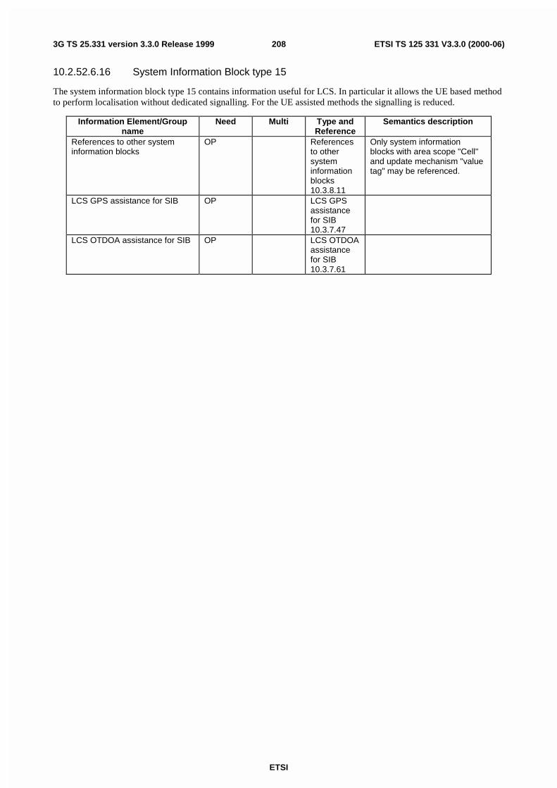
ETSI
ETSI TS 125 331 V3.3.0 (2000-06)2083G TS 25.331 version 3.3.0 Release 1999
10.2.52.6.16 System Information Block type 15
The system information block type 15 contains information useful for LCS. In particular it allows the UE based methodto perform localisation without dedicated signalling. For the UE assisted methods the signalling is reduced.
Information Element/Groupname
Need Multi Type andReference
Semantics description
References to other systeminformation blocks
OP Referencesto othersysteminformationblocks10.3.8.11
Only system informationblocks with area scope "Cell"and update mechanism "valuetag" may be referenced.
LCS GPS assistance for SIB OP LCS GPSassistancefor SIB10.3.7.47
LCS OTDOA assistance for SIB OP LCS OTDOAassistancefor SIB10.3.7.61

ETSI
ETSI TS 125 331 V3.3.0 (2000-06)2093G TS 25.331 version 3.3.0 Release 1999
10.2.52.6.16.1 System Information Block type 15.1
The system information block type 15.1 contains information useful for LCS DGPS Corrections. The DGPSCorrections message contents are based on a Type-1 message of version 2.2 of the RTCM-SC-104 recommendation fordifferential service. This format is a standard of the navigation industry and is supported by all DGPS receivers.
Information Element/Groupname
Need Multi Type andReference
Semantics description
UTRAN Time Flag MP Bitstring(1)Node B Clock Drift Flag MP Bitstring(1)Node B Clock Drift OP Real(-
0.1..0.1 by aproper step)
This IE provides an estimate ofthe drift rate of the Node Bclock relative to GPS time. Ithas units of µsec/sec (ppm)and a range of ±0.1. This IEaids the UE in maintaining therelation between GPS and celltiming over a period of time. Apositive value for Node BClock Drift indicates that theNode B clock is running at agreater frequency thandesired.
Reference Location MP As defined inTS23.032
Provides a prior knowledge ofthe approximate location of theUE
SFN OP Integer(0..4095)
The SFN that occurs at theReference GPS TOW time
Reference GPS TOW MP Integer(0..6.
047*1011)
GPS Time of Week withscaling factor of 1 usec. Thisfield time-stamps the start ofthe frame with SFN=0.
Status/Health MP Enumerated(UDRE scale1.0, UDREscale 0.75,UDRE scale0.5, UDREscale 0.3,UDRE scale0.2, UDREscale 0.1, nodata, invaliddata)
This field indicates the statusof the differential corrections.
DPGS information CV-Status 1..MAX_N_SAT
The following fields contain theDPGS corrections. If theCipher information is includedthese fields are ciphered.
>SatID MP Integer(0..31)
The satellite ID number.
>IODE MP Integer(0..255)
This IE is the sequencenumber for the ephemeris forthe particular satellite. The MScan use this IE to determine ifnew ephemeris is used forcalculating the corrections thatare provided in the broadcastmessage. This eight-bit IE isincremented for each new setof ephemeris for the satelliteand may occupy the numericalrange of [0, 239] during normaloperations.

ETSI
ETSI TS 125 331 V3.3.0 (2000-06)2103G TS 25.331 version 3.3.0 Release 1999
>UDRE MP Enumerated(UDRE ≤ 1.0m,1.0m <UDRE ≤4.0m,4.0m <UDRE ≤8.0m,8.0m <UDRE)
User Differential Range Error.This field provides an estimateof the uncertainty (1-σ) in thecorrections for the particularsatellite. The value in this fieldshall be multiplied by theUDRE Scale Factor in theStatus field to determine thefinal UDRE estimate for theparticular satellite.
>PRC MP Integer(-2047..2047)
Scaling factor 0.32 meters(different from [13])
>RRC MP Integer(-127..127)
Scaling factor 0.032meters/sec (different from [13])
>Delta PRC2 MP Integer(-127..127)
The difference in thepseudorange correctionbetween the satellite'sephemeris identified by IODEand the previous ephemeristwo issues ago IODE –2.
>Delta RRC2 MP Integer(-7..7) The difference in thepseudorange rate-of-changecorrection between thesatellite's ephemeris identifiedby IODE and IODE-2.
NOTE: Each UDRE value shall be adjusted based on the operation of an Integrity Monitor (IM) function whichexists at the network (SRNC, GPS server, or reference GPS receiver itself). Positioning errors derived atthe IM which are excessive relative to DGPS expected accuracy levels shall be used to scale the UDREvalues to produce consistency.
Multi Bound ExplanationMAX_N_SAT Maximum number of satellites included in the IE=16
Condition ExplanationStatus/Health This IE is mandatory if "status" is not equal to "no
data" or "invalid data", otherwise the IE is not needed
10.2.52.6.16.2 System Information Block type 15.2
The system information block type 15.2 contains information useful for ephemeris and clock corrections of a particularsatellite. These IE fields are extracted from the subframes 1 to 3 of the GPS navigation message [12].

ETSI
ETSI TS 125 331 V3.3.0 (2000-06)2113G TS 25.331 version 3.3.0 Release 1999
Information Element/Groupname
Need Multi Type andReference
Semantics description
Transmission TOW MP Enumerated(0. 19)
The approximate GPS time-of-week when the message isbroadcast
SatID MP Enumerated(0..63)
Satellite ID
TLM Message MP Bit string(14)TLM Revd (C) MP Bit string(2)HOW MP Bit string(22)WN MP Bit string(10)C/A or P on L2 MP Bit string(2)URA Index MP Bit string(4)SV Health MP Bit string(6)IODC MP Bit
string(10(1))
L2 P Data Flag MP Bit string(1)SF 1 Reserved MP Bit string(87)TGD MP Bit string(8)toc MP Bit
string(16(1))
af2 MP Bit string(8)af1 MP Bit string(16)af0 MP Bit string(22)Crs MP Bit string(16)
∆n MP Bit string(16)M0 MP Bit string(32)Cuc MP Bit string(16)e MP Bit
string(32(1))
Cus MP Bit string(16)
(A)1/2 MP Bit
string(32(1))
toe MP Bit
string(16(1))
Fit Interval Flag MP Bit string(1)AODO MP Bit string(5)Cic MP Bit string(16)OMEGA0 MP Bit string(32)Cis MP Bit string(16)i0 MP Bit string(32)Crc MP Bit string(16)
ω MP Bit string(32)OMEGAdot MP Bit string(24)Idot MP Bit string(14)Spare/zero fill MP Bit string(20)
10.2.52.6.16.3 System Information Block type 15.3
The system information block type 15.3 contains information useful for ionospheric delay, UTC offset, and Almanac.These IE fileds are extracted from the subframes 4 and 5 of the GPS navigation message, excluding the parity bits andother redundant bits [12].

ETSI
ETSI TS 125 331 V3.3.0 (2000-06)2123G TS 25.331 version 3.3.0 Release 1999
Information Element/Groupname
Need Multi Type andReference
Semantics description
Transmission TOW MP Enumerated(0. 19)
The approximate GPS time-of-week when the message isbroadcast
SatMask MP Enumerated(1..32)
indicates the satellites thatcontain the pages beingbroadcast in this data set
LSB TOW MP Bit string(8)GPS Info MP 1 to
<Max_Dat_rep>
>SFIO 0 MP Bit string(1)
Each repetition corresponds toa different page no. asdescribed in the table below
>Data ID MP Bit string(2)>Page No. MP Bit string(6)>Word 3 MP Bit string(16)>Word 4 MP Bit string(24)>Word 5 MP Bit string(24)>Word 6 MP Bit string(24)>Word 7 MP Bit string(24)>Word 8 MP Bit string(24)>Word 9 MP Bit string(24)>Word 10 MP Bit string(22)Spare/zero fill MP Bit string(5)
Mapping of Almanac, Health, Iono, and UTC Data to Subframe Number and Page Number
Data Type Subframe Page(s)Almanac Data (SV1 – 24) 5 1 - 24
Almanac Data (SV25 – 32) 4 2, 3, 4, 5, 7, 8, 9, 10SV Health (SV1 – 24) 5 25
SV Health (SV25 – 32) 4 25Iono/UTC Corrections 4 18
Multi Bound ExplanationMax_Dat_rep Maximum number of repeats=3
10.2.52.6.17 System Information Block type 16
The system information block type 16 contains radio bearer, transport channel and physical channel parameters to bestored by UE in idle and connected mode for use during handover to UTRAN. The block may also contain schedulinginformation for other system information blocks.

ETSI
ETSI TS 125 331 V3.3.0 (2000-06)2133G TS 25.331 version 3.3.0 Release 1999
Information Element/Groupname
Need Multi Type andReference
Semantics description
Other information elementsReferences to other systeminformation blocks
OP Referencesto othersysteminformationblocks10.3.8.11
Only system informationblocks with area scope "Cell"and update mechanism "valuetag" may be referenced.
UE information elements>Re-establishment timer MP Re-
establishment timer10.3.3.30
RB information elementsPredefined RB configuration MP Predefined
RBconfiguration10.3.4.7
TrCH Information ElementsPredefined TrCH configuration MP Predefined
TrCHconfiguration10.3.5.9
PhyCH Information ElementsPredefined PhyCH configuration MP Predefined
PhyCHconfiguration10.3.6.48
10.2.53 SYSTEM INFORMATION CHANGE INDICATION
This message is used to send information on FACH to the UEs in state CELL_FACH about coming modification of thesystem information.
RLC-SAP: TM
Logical channel: BCCH
Direction: UTRAN → UE
Information Element/Groupname
Need Multi Type andreference
Semantics description
Message Type MP MessageType
Other information elementsBCCH modification info MP BCCH
modificationinfo 10.3.8.1

ETSI
ETSI TS 125 331 V3.3.0 (2000-06)2143G TS 25.331 version 3.3.0 Release 1999
If the encoded message does not fill a transport block, the RRC layer shall insert padding according to subclause 12.x.
10.2.54 TRANSPORT CHANNEL RECONFIGURATION
This message is used by UTRAN to configure the transport channel of a UE. This also includes a possiblereconfiguration of physical channels. The message can also be used to assign a TFC subset and reconfigure physicalchannel.
RLC-SAP: AM or UM
Logical channel: DCCH
Direction: UTRAN → UE
Information Element/Groupname
Need Multi Type andreference
Semantics description
Message Type MP MessageType
UE Information ElementsIntegrity check info CH Integrity
check info10.3.3.15
Integrity protection mode info OP Integrityprotectionmode info10.3.3.18
Ciphering mode info OP Cipheringmode info10.3.3.5
Activation time MD Activationtime 10.3.3.1
Default value is "now"
New U-RNTI OP U-RNTI10.3.3.45
New C-RNTI OP C-RNTI10.3.3.8
DRX Indicator MP DRXIndicator10.3.3.10
UTRAN DRX cycle lengthcoefficient
MD UTRAN DRXcycle lengthcoefficient10.3.3.47
Default value is the existingvalue of UTRAN DRX cyclelength coefficient
CN Information ElementsCN Information info OP CN
Informationinfo 10.3.1.3
RB information elementsRB with PDCP information list OP 1 to
<maxRBallRABs>
This IE is needed for each RBhaving PDCP in the case oflossless SRNS relocation
>RB with PDCP information MP RB withPDCPinformation10.3.4.19
TrCH Information ElementsUplink transport channelsUL Transport channelinformation common for alltransport channels
OP UL Transportchannelinformationcommon forall transportchannels10.3.5.24
Added or Reconfigured TrCH information list
MP 1 to<maxTrCH>

ETSI
ETSI TS 125 331 V3.3.0 (2000-06)2153G TS 25.331 version 3.3.0 Release 1999
>Added or Reconfigured ULTrCH information
MP Added orReconfigured UL TrCHinformation10.3.5.2
CHOICE mode OP>FDD>>CPCH set ID OP CPCH set ID
10.3.5.3>> Added or Reconfigured TrCH information for DRAC list
OP 1 to<maxTrCH>
>>>DRAC static information MP DRAC staticinformation10.3.5.7
>TDD (no data)Downlink transport channelsDL Transport channelinformation common for alltransport channels
OP DL Transportchannelinformationcommon forall transportchannels10.3.5.6
Added or Reconfigured TrCH information list
MP 1 to<maxTrCH>
>Added or Reconfigured DLTrCH information
MP Added orReconfigured DL TrCHinformation10.3.5.1
PhyCH information elementsFrequency info MD Frequency
info10.3.6.30
Default value is the existingvalue of frequency information
Uplink radio resourcesMaximum allowed UL TX power MD Maximum
allowed ULTX power10.3.6.33
Default value is the existingmaximum UL TX power
CHOICE channel requirement OP At least one spare choice(criticality = reject) required
>Uplink DPCH info UplinkDPCH info10.3.6.76
>PRACH Info (for RACH) PRACH Info(for RACH)10.3.6.44
Downlink radio resourcesCHOICE mode>FDD>>Downlink informationcommon for all radio links
OP Downlinkinformationcommon forall radio links10.3.6.20
>>Downlink PDSCH information OP DownlinkPDSCHinformation10.3.6.26
>>CPCH set Info OP CPCH setInfo10.3.6.10
>TDD (no data)Downlink information per radiolink list
OP 1 to<maxRL>
Send downlink information foreach radio link

ETSI
ETSI TS 125 331 V3.3.0 (2000-06)2163G TS 25.331 version 3.3.0 Release 1999
>Downlink information for eachradio link
MP Downlinkinformationfor eachradio link10.3.6.23
10.2.55 TRANSPORT CHANNEL RECONFIGURATION COMPLETE
This message is sent from the UE when a transport channel reconfiguration has been done.
RLC-SAP: AM
Logical channel: DCCH
Direction: UE → UTRAN
Information Element/Groupname
Need Multi Type andreference
Semantics description
Message Type MP MessageType
UE information elementsIntegrity check info CH Integrity
check info10.3.3.15
Uplink integrity protectionactivation info
OP Integrityprotectionactivationinfo10.3.3.16
CHOICE mode OP>FDD (no data)>TDD>>Uplink Timing Advance OP Uplink
TimingAdvance10.3.6.82
This information element shallbe present in case of handoverprocedure. Calculated timingadvance value for the new cellafter handover in asynchronous TDD network
RB Information elementsRadio bearer uplink cipheringactivation time info
OP RBactivationtime info10.3.4.10
RB with PDCP information list OP 1 to<maxRBallRABs>
This IE is needed for each RBhaving PDCP in the case oflossless SRNS relocation
>RB with PDCP information MP RB withPDCPinformation10.3.4.19
10.2.56 TRANSPORT CHANNEL RECONFIGURATION FAILURE
This message is sent by UE if the configuration given by UTRAN is unacceptable or if the UE failed to establish thephysical channel(s).
RLC-SAP: AM
Logical channel: DCCH
Direction: UE→UTRAN

ETSI
ETSI TS 125 331 V3.3.0 (2000-06)2173G TS 25.331 version 3.3.0 Release 1999
Information Element/Groupname
Need Multi Type andreference
Semantics description
Message Type MP MessageType
UE information elementsIntegrity check info CH Integrity
check info10.3.3.15
Failure cause MP Failurecause anderrorinformation10.3.3.12
10.2.57 TRANSPORT FORMAT COMBINATION CONTROL
This message is sent by UTRAN to control the uplink transport format combination within the allowed transport formatcombination set.
RLC-SAP: TM, AM or UM
Logical channel: DCCH
Direction: UTRAN→UE
Information Element/Groupname
Need Multi Type andreference
Semantics description
Message Type CV-notTM MessageType
UE information elementsIntegrity check info CH Integrity
check info10.3.3.15
TrCH information elements DPCH TFCS in uplink MP Transport
FormatCombinationsubset10.3.5.22
TFC Control duration CV-notTMopt
TFC Controlduration10.3.6.69
Condition ExplanationNotTM The message type is not included when transmitting the
message on the transparent mode signalling DCCHNotTMopt The information element is not included when
transmitting the message on the transparent modesignalling DCCH and is optional otherwise.
If transparent mode signalling is used and the encoded message does not fill a transport block, the RRC layer shallinsert padding according to subclause 12.x.
10.2.58 TRANSPORT FORMAT COMBINATION CONTROL FAILURE
This message is sent to indicate that a received TRANSPORT FORMAT COMBINATION CONTROL message couldnot be handled by the UE.

ETSI
ETSI TS 125 331 V3.3.0 (2000-06)2183G TS 25.331 version 3.3.0 Release 1999
RLC-SAP: AM
Logical channel: DCCH
Direction: UE→UTRAN
Information Element/Groupname
Need Multi Type andreference
Semantics description
Message Type MP MessageType
UE information elementsIntegrity check info CH Integrity
check info10.3.3.15
Failure cause MP Failurecause anderrorinformation10.3.3.12
10.2.59 UE CAPABILITY ENQUIRY
The UE CAPABILITY ENQUIRY is used by the UTRAN to enquire inter-system classmarks from the UE.
RLC-SAP: TBD
Logical channel: DCCH
Direction: UTRAN → UE
Information Element/Groupname
Need Multi Type andreference
Semantics description
Message Type MP MessageType
UE information elementsIntegrity check info CH Integrity
check info10.3.3.15
Integrity check info is includedif integrity protection is applied
Capability update requirement MP Capabilityupdaterequirement10.3.3.2
10.2.60 UE CAPABILITY INFORMATION
This message is sent by UE to convey UE specific capability information to the UTRAN.
RLC-SAP: AM or UM
Logical channel: DCCH
Direction: UE → UTRAN

ETSI
ETSI TS 125 331 V3.3.0 (2000-06)2193G TS 25.331 version 3.3.0 Release 1999
Information Element/Groupname
Need Multi Type andreference
Semantics description
Message Type MP MessageType
UE information elementsIntegrity check info CH Integrity
check info10.3.3.15
Integrity check info is includedif integrity protection is applied
UE radio access capability OP UE radioaccesscapability10.3.3.40
Other information elementsUE system specific capability OP Inter-system
message10.3.8.6
Includes inter-systemclassmark
10.2.61 UE CAPABILITY INFORMATION CONFIRM
This message is sent by UTRAN to confirm that UE capability information has been received.
RLC-SAP: AM orUM
Logical channel: DCCH
Direction: UTRAN → UE
Information Element/Groupname
Need Multi Type andreference
Semantics description
Message Type MP MessageType
UE information elementsIntegrity check info CH Integrity
check info10.3.3.15
Integrity check info is includedif integrity protection is applied

ETSI
ETSI TS 125 331 V3.3.0 (2000-06)2203G TS 25.331 version 3.3.0 Release 1999
10.2.62 UPLINK DIRECT TRANSFER
This message is used to transfer NAS messages for an on-going signalling flow. RLC-SAP: AM
Logical channel: DCCH
Direction: UE ->UTRAN
Information Element/Groupname
Need Multi Type andreference
Semantics description
Message Type MP MessageType
UE information elementsIntegrity check info CH Integrity
check info10.3.3.15
Integrity check info is includedif integrity protection is applied
CN information elementsFlow Identifier MP Flow
Identifier10.3.1.4
Allocated by UE for aparticular flow
NAS message MP NASmessage10.3.1.8
Measurement informationelementsMeasured results on RACH OP Measured
results onRACH10.3.7.70
10.2.63 UPLINK PHYSICAL CHANNEL CONTROL
NOTE: Only for TDD.
In TDD this message is used to transfer uplink physical channel parameters to the UE.
RLC-SAP: AM or UM
Logical channel: DCCH
Direction: UTRAN→UE
Information Element/Groupname
Need Multi Type andReference
Semantics description
Message Type MP MessageType
UE information elementsIntegrity check info OP Integrity
check info10.3.3.15
PhyCH information elementsCCTrCH power control info OP CCTrCH
powercontrol info10.3.6.6
Power control information forone CCTrCH
Timing Advance OP UL TimingAdvance10.3.6.82
Timeslot List OP 1 to<maxTS>
>Individual UL Timeslotinterference
MP IndividualTimeslotinterference10.3.6.32

ETSI
ETSI TS 125 331 V3.3.0 (2000-06)2213G TS 25.331 version 3.3.0 Release 1999
PRACH Constant Value OP Constantvalue10.3.6.8
Operator controlled PRACHMargin
DPCH Constant Value OP Constantvalue10.3.6.8
Operator controlled UL DPCHMargin
PUSCH Constant Value OP Constantvalue10.3.6.8
Operator controlled PUSCHMargin
10.2.64 URA UPDATE
This message is used by the UE to initiate a URA update procedure.
RLC-SAP: TM
Logical channel: CCCH
Direction: UE→UTRAN
Information Element/Groupname
Need Multi Type andreference
Semantics description
Message Type MP MessageType
UE information elementsU-RNTI MP U-RNTI
10.3.3.45Integrity check info CH Integrity
check info10.3.3.15
URA update cause MP URA updatecause10.3.3.44
Protocol error indicator MD Protocolerrorindicator10.3.3.28
Default value is FALSE
Other information elementsProtocol error information CV-ProtErr Protocol
errorinformation10.3.8.10
Condition ExplanationProtErr If the IE "Protocol error indicator" has the value
"TRUE"

ETSI
ETSI TS 125 331 V3.3.0 (2000-06)2223G TS 25.331 version 3.3.0 Release 1999
10.2.65 URA UPDATE CONFIRM
This message confirms the URA update procedure and can be used to reallocate new RNTI information for the UE validafter the URA update.
RLC-SAP: UM
Logical channel: CCCH or DCCH
Direction: UTRAN→UE
Information Element/Groupname
Need Multi Type andreference
Semantics description
Message Type MP MessageType
UE information elementsU-RNTI CV-CCCH U-RNTI
10.3.3.45Integrity check info CH Integrity
check info10.3.3.15
Integrity check info is includedif integrity protection is applied
Integrity protection mode info OP Integrityprotectionmode info10.3.3.18
Ciphering mode info OP Cipheringmode info10.3.3.5
New U-RNTI OP U-RNTI10.3.3.45
New C-RNTI OP C-RNTI10.3.3.8
DRX Indicator MP DRXIndicator10.3.3.10
UTRAN DRX cycle lengthcoefficient
MD UTRAN DRXcycle lengthcoefficient10.3.3.47
Default value is the existingvalue of UTRAN DRX cyclelength coefficient
CN Information ElementsCN Information info OP CN
Informationinfo 10.3.1.3
UTRAN mobility informationelementsURA identity OP URA identity
10.3.2.6RB information elementsRB with PDCP information list OP 1 to
<maxRBallRABs>
This IE is needed for each RBhaving PDCP in the case oflossless SRNS relocation
>RB with PDCP information MP RB withPDCPinformation10.3.4.19
Condition ExplanationCCCH This IE is only sent when CCCH is used
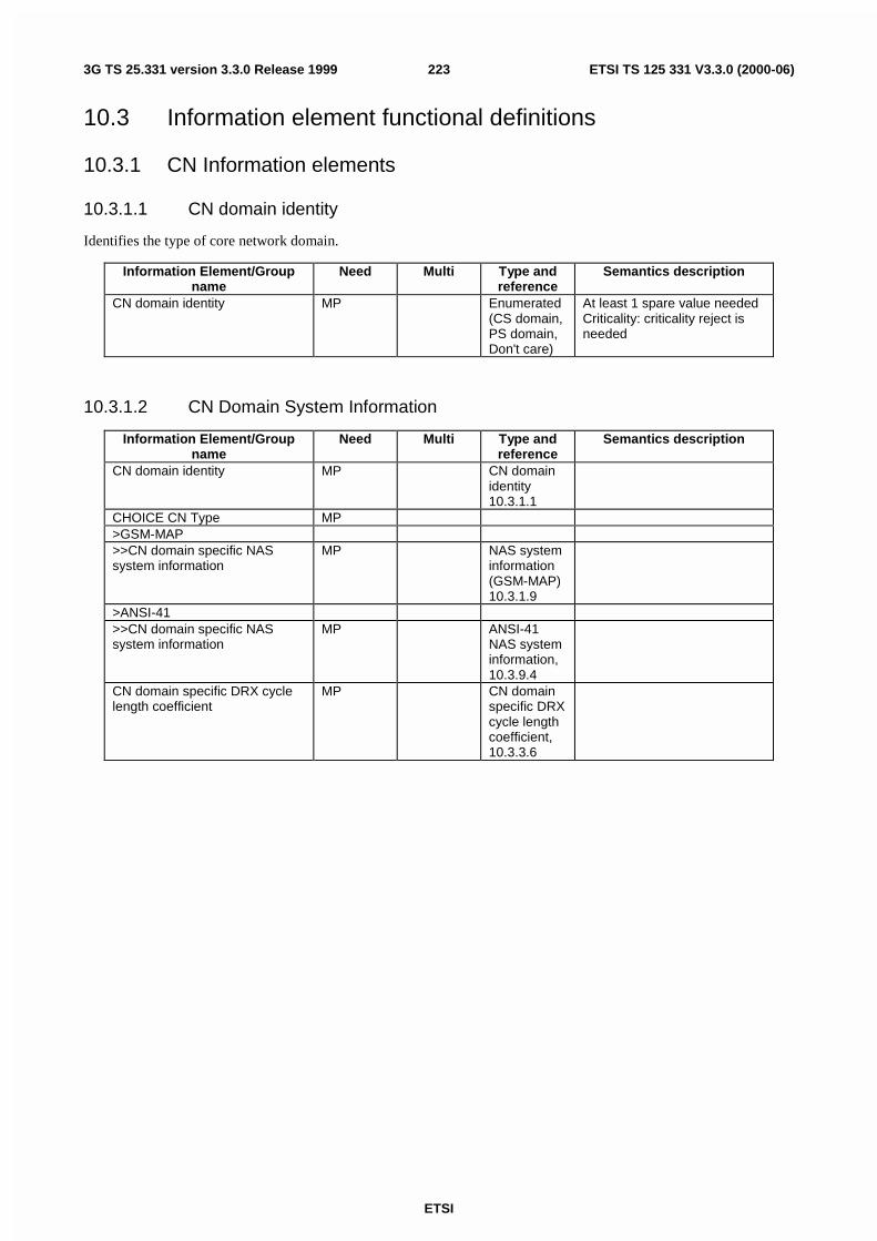
ETSI
ETSI TS 125 331 V3.3.0 (2000-06)2233G TS 25.331 version 3.3.0 Release 1999
10.3 Information element functional definitions
10.3.1 CN Information elements
10.3.1.1 CN domain identity
Identifies the type of core network domain.
Information Element/Groupname
Need Multi Type andreference
Semantics description
CN domain identity MP Enumerated(CS domain,PS domain,Don't care)
At least 1 spare value neededCriticality: criticality reject isneeded
10.3.1.2 CN Domain System Information
Information Element/Groupname
Need Multi Type andreference
Semantics description
CN domain identity MP CN domainidentity10.3.1.1
CHOICE CN Type MP>GSM-MAP>>CN domain specific NASsystem information
MP NAS systeminformation(GSM-MAP)10.3.1.9
>ANSI-41>>CN domain specific NASsystem information
MP ANSI-41NAS systeminformation,10.3.9.4
CN domain specific DRX cyclelength coefficient
MP CN domainspecific DRXcycle lengthcoefficient,10.3.3.6

ETSI
ETSI TS 125 331 V3.3.0 (2000-06)2243G TS 25.331 version 3.3.0 Release 1999
10.3.1.3 CN Information info
Information Element/Groupname
Need Multi Type andreference
Semantics description
PLMN identity OP PLMNidentity10.3.1.11
CN common GSM-MAP NASsystem information
OP NAS systeminformation(GSM-MAP)10.3.1.9
CN domain related information OP 1 to<maxCNdomains>
>CN domain identity MP CN domainidentity10.3.1.1
>CN domain specific GSM-MAPNAS system info
MPNAS systeminformation(GSM-MAP)10.3.1.9
NOTE 1: Necessity of PLMN is FFS and for CN domain identity and NAS system information, the confirmation inSA WG2 is needed.
10.3.1.4 Flow Identifier
This IE is allocated by the UE for a particular signalling flow on an indication from the upper layers.
Information Element/Groupname
Need Multi Type andreference
Semantics description
Flow Identifier MP Integer(0…63)
10.3.1.5 IMEI
This IE contains an International Mobile Equipment Identity. Setting specified in [TS 23.003]
Information Element/Groupname
Need Multi Type andreference
Semantics description
IMEI MP 15>IMEI digit MP INTEGER(0.
.15)
10.3.1.6 IMSI (GSM-MAP)
This IE contains an International Mobile Subscriber Identity, used towards a GSM-MAP type of PLMN. Settingspecified in [TS 23.003]
Information Element/Groupname
Need Multi Type andreference
Semantics description
IMSI MP 6 to 15>IMSI digit MP INTEGER(0.
.9)
10.3.1.7 Location Area Identification
Identifies uniquely a location area for a GSM-MAP type of PLMN. Setting specified in [TS24.008].

ETSI
ETSI TS 125 331 V3.3.0 (2000-06)2253G TS 25.331 version 3.3.0 Release 1999
Information Element/Groupname
Need Multi Type andreference
Semantics description
PLMN identity MP PLMNidentity10.3.1.11
LAC MP Bit string(16)
10.3.1.8 NAS message
A non-access stratum message to be transferred transparently through UTRAN.
Information Element/Groupname
Need Multi Type andreference
Semantics description
NAS message MP Octet string(1..4095)
10.3.1.9 NAS system information (GSM-MAP)
This information element contains system information that belongs to the non-access stratum for a GSM-MAP type ofPLMN. This information is transparent to RRC. It may contain either information specific to one CN domain (CS orPS) or information common for both CN domains.
Information Element/Groupname
Need Multi Type andreference
Semantics description
GSM-MAP NAS systeminformation
MP Octetstring(1..8 )
10.3.1.10 Paging record Type identifier
Information Element/Groupname
Need Multi Type andreference
Semantics description
Paging Record Type Identifier MP Enumerated(IMSI (GSM-MAP), TMSI(GSM-MAP)/P-TMSI,IMSI (DS-41), TMSI(DS-41))
10.3.1.11 PLMN identity
This information element identifies a Public Land Mobile Network for a GSM-MAP type of PLMN. Setting of digits isdefined in [TS 23.003].
Information Element/Groupname
Need Multi Type andreference
Semantics description
MCC MP 3>MCC digit MP INTEGER(0..9)MNC MP 2 to 3>MNC digit MP INTEGER(0..9)
10.3.1.12 PLMN Type
Identifies the type of Public Land Mobile Network (PLMN). This IE shall be used to control the interpretation ofnetwork dependent messages and information elements in the RRC protocol.

ETSI
ETSI TS 125 331 V3.3.0 (2000-06)2263G TS 25.331 version 3.3.0 Release 1999
Information Element/Groupname
Need Multi Type andreference
Semantics description
PLMN Type MP Enumerated(GSM-MAP,ANSI-41,GSM-MAPand ANSI-41)
At least 1 spare valueneededCriticality: reject is needed
10.3.1.13 P-TMSI (GSM-MAP)
This IE contains a Packet Temporary Mobile Subscriber Identity, used towards a GSM-MAP type of PLMN.
Information Element/Groupname
Need Multi Type andreference
Semantics description
P-TMSI MP Bit string(32)
Setting specified in[TS 23.003]
10.3.1.14 RAB identity
This information element uniquely identifies a radio access bearer within a CN domain.
Information Element/Groupname
Need Multi Type andreference
Semantics description
CHOICE RAB identity type MP>RAB identity (GSM-MAP) Bit string (8) Formatted according to
[TS 24.008].>RAB identity (ANSI-41) Bit string (8)
CHOICE NAS binding info type Condition under which the given RAB identitytype is chosen
RAB identity (GSM-MAP) PLMN is of type GSM-MAPRAB identity (ANSI-41) PLMN is of type ANSI-41
10.3.1.15 Routing Area Code
Identifies a routing area within a location area for a GSM-MAP type of PLMN.
Information Element/Groupname
Need Multi Type andreference
Semantics description
Routing Area Code MP Bit string(8) Setting specified in[TS 23.003]
10.3.1.16 Routing Area Identification
Identifies uniquely a routing area for a GSM-MAP type of PLMN. Setting specified in [TS 23.003].
Information Element/Groupname
Need Multi Type andreference
Semantics description
LAI MP Locationareaidentification10.3.1.7
RAC MP Routing areacode10.3.1.15

ETSI
ETSI TS 125 331 V3.3.0 (2000-06)2273G TS 25.331 version 3.3.0 Release 1999
10.3.1.17 Service Descriptor
Identifies a service and/or a protocol entity in the core network.
Information Element/Groupname
Need Multi Type andreference
Semantics description
CHOICE Service descriptor type MP>Service Descriptor (GSM-MAP) Bit string (4) Protocol Discriminator [TS
24.007]The value of RR in the abovereference is reserved forpaging response.
>Service Descriptor (ANSI-41) Bit string(4) TIA/EIA IS-834
CHOICE Service descriptor type Condition under which the given Servicedescriptor type is chosen
Service descriptor (GSM-MAP) PLMN is of type GSM-MAPService descriptor (ANSI-41) PLMN is of type ANSI-41
10.3.1.18 TMSI (GSM-MAP)
This IE contains a Temporary Mobile Subscriber Identity, used towards a GSM-MAP type of PLMN.
Information Element/Groupname
Need Multi Type andreference
Semantics description
TMSI (GSM-MAP) MP Bit string(32)
Setting specified in[TS 23.003]
10.3.2 UTRAN mobility Information elements
10.3.2.1 Cell Access Restriction
Indicates the restrictions to cell access.

ETSI
ETSI TS 125 331 V3.3.0 (2000-06)2283G TS 25.331 version 3.3.0 Release 1999
Information Element/Groupname
Need Multi Type andreference
Semantics description
Cell Barred MP Enumerated(not barred,barred)
Intra-frequency cell re-selectionindicator
CV-Barred Enumerated(not allowed,allowed)
Tbarred CV-Barred Integer(10,20,40,80,160,320,640,1280)
[4](TS25.304)
Cell Reserved for operator use MP Enumerated(reserved, notreserved)
Cell Reserved for SoLSAexclusive use
MP Enumerated(reserved, notreserved)
Access Class Barred list MD maxAC Default is no access classbarred is applied.The first instance of theparameter corresponds toAccess Class 0, the second toAccess Class 1 and so on upto Access Class 15. UE readsthis IE of its access classstored in SIM.
>Access Class Barred MP Enumerated(not barred,barred)
Condition ExplanationBarred Presence is mandatory if the IE "Cell Barred" has the
value "Barred"; otherwise the element is not neededin the message.
10.3.2.2 Cell identity
This information element identifies a cell unambiguously within a PLMN.
Information Element/Groupname
Need Multi Type andreference
Semantics description
Cell identity MP bit string(28)

ETSI
ETSI TS 125 331 V3.3.0 (2000-06)2293G TS 25.331 version 3.3.0 Release 1999
10.3.2.3 Cell selection and re-selection info for SIB3/4
Information Element/Groupname
Need Multi Type andreference
Semantics description
Mapping Info MD Mapping info10.3.2.5
Contains mapping function forquality measurements. Defaultis an implicit mapping: Qmap =Qmeas,LEV, TS 25.304.
CHOICE mode MP>FDD>>Cell_selection_and_reselection_quality_measure
MP Enumerated(CPICHEc/N0,CPICHRSCP)
Choice of measurement(CPICH Ec/N0 or CPICHRSCP) to use as qualitymeasure Q.
>>Sintrasearch OP Integer (-32..20 bystep of 2)
TS 25.304[dB]
>>Sintersearch OP Integer (-32..20 bystep of 2)
TS 25.304[dB]
>>SsearchHCS OP Integer (-32..20 bystep of 2)
TS 25.304[dB]
>>RAT List OP 1 to<maxOtherRAT>
>>>RAT identifier MP Enumerated(GSM,cdma2000)
At least 2 spare valuesCriticality: reject are needed
>>>Ssearch,RAT MP Integer (-32..20 bystep of 2)
TS 25.304[dB]
>>>SHCS,RAT OP Integer (-32..20 bystep of 2)
TS 25.304[dB]
>TDD>>Sintrasearch OP Integer (-
105..91 bystep of 2)
TS 25.304[dB]

ETSI
ETSI TS 125 331 V3.3.0 (2000-06)2303G TS 25.331 version 3.3.0 Release 1999
>>Sintersearch OP Integer (-105..91 bystep of 2)
TS 25.304[dB]
>>SsearchHCS OP Integer (-105..91 bystep of 2)
TS 25.304[dB]
>>RAT List OP 1 to<maxOtherRAT>
>>>RAT identifier MP Enumerated(GSM,cdma2000)
At least 2 spare valuesCriticality: reject are needed
>>>Ssearch,RAT OP Integer (-105..91 bystep of 2)
TS 25.304[dB]
>>>SHCS,RAT OP Integer (-105..91 bystep of 2)
TS 25.304[dB]
Qhysts MP Integer(0..40 bystep of 2)
Treselections MP Integer(0..31)
[s]
HCS Serving cell Information OP HCS Servingcellinformation10.3.7.12
Maximum allowed UL TX power MP Maximumallowed ULTX power10.3.6.33
[dBm]UE_TXPWR_MAX_RACH in25.304.
CHOICE mode MP>FDD>>Qqualmin MD Integer (-
20..0)Ec/N0, [dB]Default value is Qrxlevmin forthe serving cell
>>>Qrxlevmin MD Integer (-115..-25 bystep of 2)
RSCP, [dBm]Default value is Qrxlevmin forthe serving cell
>TDD>>Qrxlevmin MP Integer (-
115..-25 bystep of 2)
RSCP, [dBm]Default value is Qrxlevmin forthe serving cell

ETSI
ETSI TS 125 331 V3.3.0 (2000-06)2313G TS 25.331 version 3.3.0 Release 1999
10.3.2.4 Cell selection and re-selection info for SIB11/12
Information Element/Groupname
Need Multi Type andreference
Semantics description
Qoffsets,n MD Real(-50.0..50.0 bystep of 1)
Default value is 0.
Maximum allowed UL TX power MD Maximumallowed ULTX power10.3.6.33
[dBm]UE_TXPWR_MAX_RACH in25.304.Default is the Maximumallowed UL TX power for theserving cell
HCS neighbouring cellinformation
OP HCSNeighbouring cellinformation10.3.7.11
CHOICE mode MP>FDD>>Qqualmin MD Integer (-
20..0)Ec/N0, [dB]Default value is Qqualmin forthe serving cell
>>Qrxlevmin MD Integer (-115..-25 bystep of 2)
RSCP, [dBm]Default value is Qrxlevmin forthe serving cell
>TDD>>Qrxlevmin MD Integer (-
115..-25 bystep of 2)
RSCP, [dBm]Default value is Qrxlevmin forthe serving cell

ETSI
ETSI TS 125 331 V3.3.0 (2000-06)2323G TS 25.331 version 3.3.0 Release 1999
10.3.2.5 Mapping Info
Information Element/Groupname
Need Multi Type andReference
Semantics description
Mapping List MP 1 to<MaxRAT>
>RAT MP Enumerated(UTRA FDD,UTRA TDD,GSM,cdma2000)
>Mapping Function ParameterList
MP 1 to<maxMeasIntervals>
>> Function type MP Enumerated(linear,function type2, functiontype 3,function type4)
Type of the function within theinterval.
>>Map_parameter_1 MD Integer(0..99)
Parameter describing themapping function between thequality measurement and therepresenting quality value, seeTS 25.304.Default value is zero for thefirst interval or otherwise thevalue of Map_parameter_2 ofthe interval before.
>>Map_parameter_2 MP Integer(0..99)
Parameter describing themapping function between thequality measurement and therepresenting quality value, seeTS 25.304.
>>Upper_limit CV -MaxInt
Integer(1..MaxMeas)
Upper limit of interval for whichthe Map_parameter_1 andMap_parameter_2 are valid.MaxMeas = 25 if RAT = UTRAFDD / CPICH Ec/N0,MaxMeas = 91 if RAT = UTRATDD or if RAT = UTRA FDD/CPICH RSCP,MaxMeas = 63 if RAT = GSM.
Condition ExplanationMaxInt This information is only sent if Mapping Function
Parameter List has not reached maxMeasIntervals.
10.3.2.6 URA identity
Gives the identity of the UTRAN Registration Area. It can be used to indicate to the UE which URA it shall use in caseof overlapping URAs.
Information Element/Groupname
Need Multi Type andreference
Semantics description
URA identity MP bit string(16)

ETSI
ETSI TS 125 331 V3.3.0 (2000-06)2333G TS 25.331 version 3.3.0 Release 1999
10.3.3 UE Information elements
10.3.3.1 Activation time
Activation Time defines the CFN (Connection Frame Number) in which the operation/changes caused by the relatedmessage should be executed.
Information Element/Groupname
Need Multi Type andreference
Semantics description
Activation time MP Integer(0..255)
CFN [TS 25.402]
10.3.3.2 Capability Update Requirement
This IE indicates to the UE which specific capabilities to transfer to the network.
Information Element/Groupname
Need Multi Type andreference
Semantics description
UE radio access capabilityupdate requirement
MP Boolean TRUE indicates updaterequired
System specific capabilityupdate requirement list
OP 1 to<maxSystemCapability>
>System specific capabilityupdate requirement
MP Enumerated(GSM)
At least 15 spare valuesCriticality: reject are needed
Default value is:
"UE radio capability update requirement" = false
"System specific capability update requirement" not present.
10.3.3.3 Cell update cause
Indicates the cause for s cell update.
Information Element/Groupname
Need Multi Type andreference
Semantics description
Cell update cause MP Enumerated(cellreselection,periodic cellupdate, ULdatatransmission, pagingresponse,RB controlresponse)
At least 3 spare values,Criticality: reject, are needed

ETSI
ETSI TS 125 331 V3.3.0 (2000-06)2343G TS 25.331 version 3.3.0 Release 1999
10.3.3.4 Ciphering Algorithm
Information Element/Groupname
Need Multi Type andreference
Semantics description
Ciphering algorithm MP Bit string(4)("00002":UEA0, noencryption;"00012":UEA1, Kasumi.)
10.3.3.5 Ciphering mode info
This information element contains the ciphering specific security mode control information.
Information Element/Groupname
Need Multi Type andreference
Semantics description
Ciphering mode command MP Enumerated(start/restart,stop)
Ciphering algorithm CV-notStop
Cipheringalgorithm10.3.3.4
Activation time for DPCH OP Activationtime10.3.3.1
Used for radio bearersmapped on RLC-TM
Radio bearer downlink cipheringactivation time info
OP RBactivationtime info,10.3.4.10
Used for radio bearersmapped on RLC-AM or RLC-UM
Condition ExplanationnotStop The IE is mandatory if the IE "Ciphering mode
command" has the value "start/restart", otherwise the IEis not needed in the message.
10.3.3.6 CN domain specific DRX cycle length coefficient
A coefficient in the formula to count the paging occasions to be used by a specific UE (specified in 25.304) .
Information Element/Groupname
Need Multi Type andreference
Semantics description
CN domain specific DRX cyclelength coefficient
MP Integer(6...12) Refers to 'k' in the formulaas specified in 25.304,Discontinuous reception
10.3.3.7 CPCH Parameters
NOTE: Only for FDD.
These parameters are used by any UE using any CPCH set allocated to the Node B that is broadcasting this systeminformation.

ETSI
ETSI TS 125 331 V3.3.0 (2000-06)2353G TS 25.331 version 3.3.0 Release 1999
Information Element/Groupname
Need Multi Type andreference
Semantics description
Initial Priority Delay OP 1 tomaxASC
Initial delays for ASC priority.
>NS_IP MP Integer(0…28)
Number of slots for initial fixeddelay for each ASC prioritylevel
Backoff control parameters MP>N_ap_retrans_max MP Integer
(1…64)Max number of APtransmissions without AP-AICH response, a PHYparameter.
>N_access_fails MP Integer(1…64)
Max number of preambleramping cycles when NAKresponse received, a MACparameter.
>NF_bo_no aich MP Integer(0…31)
Number of frames for UEbackoff after N ap_retrans_max
unsuccessful AP accessattempts, a MAC parameter.
>NS_bo_busy MP Integer(0…63)
Number of slots for UE fixedbackoff after access attempt tobusy CPCH, a MACparameter.
>NF_bo_all_busy MP Integer(0…31)
Max number of frames for UEbackoff after access attempt tolast busy CPCH, a MACparameter. UE randomlyselects backoff value fromrange (0..NF_bo_all_busy)
>NF_bo_ mismatch MP Integer(0…127)
Max number of frames for theUE backoff after receivedmismatch on CD/CA-ICH, aMAC parameter. UE randomlyselects backoff value fromrange (0..NF_bo_mismatch)
>T_CPCH MP Enumerated (0, 1)
CPCH channel timing used todetermine Tau, a PHYparameter
Power Control Algorithm MP Enumerated(algorithm1,algorithm2)
Specifies algorithm to be usedby UE to interpret TPCcommands
TPC step size CV algo Integer (1,2)
In dB

ETSI
ETSI TS 125 331 V3.3.0 (2000-06)2363G TS 25.331 version 3.3.0 Release 1999
DL DPCCH BER MP Integer(0..63)
The BER quality value shall beset in the range0 ≤ DPCCH BER ≤ 1in the unit BER_dB where:
BER_dB_0: DPCCH BER = 0
BER_dB_1: -∞ <Log10(DPCCH BER) < -4.03
BER_dB_2: -4.03 ≤Log10(DPCCH BER) < -3.965
BER_dB_3: -3.965 ≤Log10(DPCCH BER) < -3.9...BER_dB_61: -0.195 ≤Log10(DPCCH BER) < -0.13
BER_dB_62: -0.13 ≤Log10(DPCCH BER) < -0.065
BER_dB_63: -0.065 ≤Log10(DPCCH BER) ≤ 0
Condition Explanationalgo The IE is mandatory if "Power Control Algorithm" is
set to "algorithm 1", otherwise the IE is not needed
10.3.3.8 C-RNTI
The cell RNTI (C-RNTI) identifies an UE having a RRC connection within a cell.
Information Element/Groupname
Need Multi Type andreference
Semantics description
C-RNTI MP bit string(16)
10.3.3.9 DRAC system information
Information element Need Multi Type andreference
Semantics description
DRAC system information MP 1 to<maxDRACclasses>
DRAC information is sent foreach class of terminal
>Transmission probability MP Transmission probability10.3.3.37
>Maximum bit rate MP Maximum bitrate10.3.3.20
10.3.3.10 DRX Indicator
Indicates to a UE if DRX shall be used with Cell updating or URA updating or if no DRX at all shall be used.

ETSI
ETSI TS 125 331 V3.3.0 (2000-06)2373G TS 25.331 version 3.3.0 Release 1999
Information Element/Groupname
Need Multi Type andreference
Semantics description
DRX indicator MP Enumerated(noDRX, DRX withcell updating,DRX with URAupdating)
At least 1 spare value,Criticality: reject, areneeded
10.3.3.11 Establishment cause
Cause for an RRC connection establishment request.
Information Element/Groupname
Need Multi Type and reference Semanticsdescription
Establishment cause MP Enumerated(Originating Conversational Call,Originating Streaming Call,Originating Interactive Call,Originating BackgroundCall,Terminating ConversationalCall,Terminating Streaming Call,Terminating Interactive Call,Terminating Background Call,Emergency Call,Inter-system cell re-selection,Registration,
Detach,SMS,Call re-establishment)
At least 18 sparevalues, Criticality:reject, are needed
NOTE: These causes shall be aligned with causes received from higher layers.
10.3.3.12 Failure cause and error information
Cause for failure to perform the requested procedure.
Information Element/Groupname
Need Multi Type andreference
Semantics description
Failure cause MP Enumerated(Configurationunacceptable,physical channelfailure,incompatiblesimultaneousreconfiguration,protocol error)
At least 3 spare values,Criticality: reject, areneeded
Protocol error information CV-ProtErr Protocol errorinformation10.3.8.10
Condition ExplanationProtErr Presence is mandatory if the IE "Failure cause" has
the value "Protocol error"; otherwise the element isnot needed in the message.

ETSI
ETSI TS 125 331 V3.3.0 (2000-06)2383G TS 25.331 version 3.3.0 Release 1999
10.3.3.13 Hyper Frame Number
The hyper frame number (HFN) is used to initialise both COUNT-C and COUNT-I for the ciphering and integrityprotection algorithms, respectively.
Information Element/Groupname
Need Multi Type andReference
Semantics description
HFN MP Bit string(20)
Start value for uplink anddownlink COUNT-C andCOUNT-I.For RBs using RLCtransparent mode, zerosshould be added, as LSB, toform a HFN of 24 bits.For RLC unacknowledgedmode, zeros shall be added,as LSB, to form a HFN of 25bitsFor integrity protectionfunction, zeros shall be added,as LSB to form a HFN of 28bits.
10.3.3.14 Initial UE identity
This information element identifies the UE at a request of an RRC connection.
Information Element/Groupname
Need Multi Type andreference
Semantics description
CHOICE UE id type MP At least 8 spare choices,Criticality: reject, is needed
>IMSI (GSM-MAP) IMSI (GSM-MAP)10.3.1.6
>TMSI and LAI (GSM-MAP)>>TMSI (GSM-MAP) MP TMSI (GSM-
MAP)10.3.1.18
>>LAI (GSM-MAP) MP LocationAreaIdentification10.3.1.7
>P-TMSI and RAI (GSM-MAP)>>P-TMSI (GSM-MAP) MP P-TMSI
(GSM-MAP)10.3.1.13
>>RAI (GSM-MAP) MP Routing AreaIdentification10.3.1.16
>IMEI IMEI10.3.1.5
>ESN (DS-41) TIA/EIA/IS-2000-4
>IMSI (DS-41) TIA/EIA/IS-2000-4
>IMSI and ESN (DS-41) TIA/EIA/IS-2000-4
>TMSI (DS-41) TIA/EIA/IS-2000-4

ETSI
ETSI TS 125 331 V3.3.0 (2000-06)2393G TS 25.331 version 3.3.0 Release 1999
10.3.3.15 Integrity check info
The Integrity check info contains the RRC message sequence number needed in the calculation of XMAC-I [TS 33.102]and the calculated MAC-I.
Information Element/Groupname
Need Multi Type andreference
Semantics description
Message authentication code MP bit string(32) MAC-I [TS 33.102]RRC Message sequencenumber
MP Integer(0..15)
The local RRC hyper framenumber (HFN) is concatenatedwith the RRC messagesequence number to form theinput parameter COUNT-I forthe integrity protectionalgorithm.
10.3.3.16 Integrity protection activation info
This IE contains the time, in terms of RRC sequence numbers, when a new integrity protection configuration shall beactivated for the signalling radio bearers.
Information Element/Groupname
Need Multi Type andreference
Semantics description
RRC message sequencenumber list
MP 4 to 5 The RRC sequence numberwhen a new integrityprotection configuration shallbe applied, for CCCH andsignalling radio bearers in theorder RB0, RB1, RB2, RB3,RB4.
>RRC message sequencenumber
MP Integer (0..15)
10.3.3.17 Integrity protection Algorithm
Information Element/Groupname
Need Multi Type andreference
Semantics description
Integrity protection algorithm MP Bit string(4)("00012":UIA1, Kasumi.)
10.3.3.18 Integrity protection mode info
Information Element/Groupname
Need Multi Type andreference
Semantics description
Integrity protection modecommand
MP Enumerated(start, modify)
At least 2 spare values,Criticality: reject, are needed
Downlink integrity protectionactivation info
CV-modify Integrityprotectionactivationinfo10.3.3.16
Integrity protection algorithm OP Integrityprotectionalgorithm10.3.3.17
Integrity protection initialisationnumber
CV-start Bitstring(32) FRESH [TS 33.102]

ETSI
ETSI TS 125 331 V3.3.0 (2000-06)2403G TS 25.331 version 3.3.0 Release 1999
Condition ExplanationStart The IE is mandatory if the IE "Integrity protection mode
command" has the value "start ", otherwise it is notneeded in the message.
Modify The IE is only present if the IE "Integrity protectionmode command" has the value "modify"
10.3.3.19 LCS capability
Information Element/Groupname
Need Multi Type andreference
Semantics description
Standalone location method(s)supported
MP Boolean Defines if a UE can measureits location by some meansunrelated to UTRANTRUE means supported
UE based OTDOA supported MP Boolean TRUE means supportedNetwork Assisted GPS support MP Enumerated
('Networkbased', 'UEbased','Both','None')
Defines if the UE supportsnetwork based or UE basedGPS methods.
GPS reference time capable MP Boolean Defines if a UE has thecapability to measure GPSreference time as defined in25.215.TRUE means capable
Support for IPDL MP Boolean Defines if a UE has thecapability to use IPDL toenhance its 'SFN-SFNobserved time difference –type2' measurement.TRUE means supported
10.3.3.20 Maximum bit rate
NOTE: Only for FDD.
Indicates the maximum user bit rate allowed on a DCH controlled by DRAC procedure for the transmission period(Transmission time validity).
Information Element/Groupname
Need Multi Type andreference
Semantics description
Maximum bit rate MP integer(0..512by step of 16)
=kbit/s
10.3.3.21 Measurement capability

ETSI
ETSI TS 125 331 V3.3.0 (2000-06)2413G TS 25.331 version 3.3.0 Release 1999
Information Element/Groupname
Need Multi Type andreference
Semantics description
Need for downlinkcompressed modeFDD measurements DL MP Boolean TRUE means that the UE
requires DL compressed modein order to performmeasurements on FDD
TDD measurements DL CVtdd_sup
Boolean TRUE means that the UErequires DL compressed modein order to performmeasurements on TDD
GSM measurements DL CVgsm_sup
> GSM 900 DL MP Boolean TRUE means that the UErequires DL compressed modein order to performmeasurements on GSM 900
> DCS 1800 DL MP Boolean TRUE means that the UErequires DL compressed modein order to performmeasurements on DCS 1800
> GSM 1900 DL MP Boolean TRUE means that the UErequires DL compressed modein order to performmeasurements on GSM 1900
Multi-carrier measurement DL CVmc_sup
Boolean TRUE means that the UErequires DL compressed modein order to performmeasurements on multi-carrier
Need for uplink compressedmodeFDD measurements UL MP Boolean TRUE means that the UE
requires UL compressed modein order to performmeasurements on FDD
TDD measurements UL CVtdd_sup
Boolean TRUE means that the UErequires UL compressed modein order to performmeasurements on TDD
GSM measurements UL CVgsm_sup
> GSM 900 UL MP Boolean TRUE means that the UErequires UL compressed modein order to performmeasurements on GSM 900
> DCS 1800 UL MP Boolean TRUE means that the UErequires UL compressed modein order to performmeasurements on DCS 1800
> GSM 1900 UL MP Boolean TRUE means that the UErequires UL compressed modein order to performmeasurements on GSM 1900
Multi-carrier measurement UL CVmc_sup
Boolean TRUE means that the UErequires UL compressed modein order to performmeasurements on multi-carrier

ETSI
ETSI TS 125 331 V3.3.0 (2000-06)2423G TS 25.331 version 3.3.0 Release 1999
Condition Explanationtdd_sup Presence is mandatory if IE Multi-mode capability =
TDD. Otherwise this field is not needed in themessage.
gsm_sup Presence is mandatory if IE Multi-RAT capability =GSM. Otherwise this field is not needed in themessage.
mc_sup Presence is mandatory if IE Multi-RAT capability =multi-carrier. Otherwise this field is not needed in themessage.
10.3.3.22 Number of RRC Message Transmissions
This IE indicates how many times the receiver of a message containing this IE shall transmit the RRC responsemessage.
Information Element/Groupname
Need Multi Type andreference
Semantics description
Number of RRC MessageTransmissions
MP Integer(1..8)
10.3.3.23 Paging cause
Cause for a CN originated page.
Information Element/Groupname
Need Multi Type and reference Semanticsdescription
Paging cause MP Enumerated(Terminating ConversationalCall,Terminating Streaming Call,Terminating Interactive Call,Terminating Background Call,SMS)
At least 4 sparevalues, Criticality:reject, are needed
NOTE: These causes shall be aligned with causes received from higher layers.
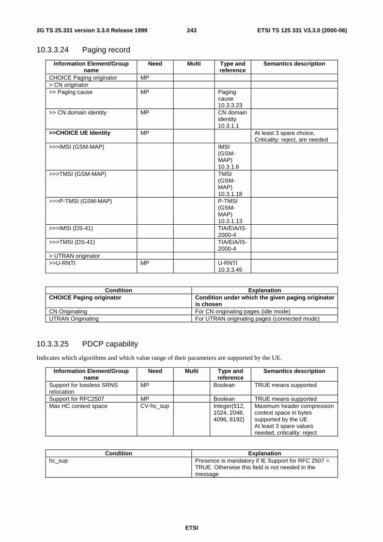
ETSI
ETSI TS 125 331 V3.3.0 (2000-06)2433G TS 25.331 version 3.3.0 Release 1999
10.3.3.24 Paging record
Information Element/Groupname
Need Multi Type andreference
Semantics description
CHOICE Paging originator MP> CN originator>> Paging cause MP Paging
cause10.3.3.23
>> CN domain identity MP CN domainidentity10.3.1.1
>>CHOICE UE Identity MP At least 3 spare choice,Criticality: reject, are needed
>>>IMSI (GSM-MAP) IMSI(GSM-MAP)10.3.1.6
>>>TMSI (GSM-MAP) TMSI(GSM-MAP)10.3.1.18
>>>P-TMSI (GSM-MAP) P-TMSI(GSM-MAP)10.3.1.13
>>>IMSI (DS-41) TIA/EIA/IS-2000-4
>>>TMSI (DS-41) TIA/EIA/IS-2000-4
> UTRAN originator>>U-RNTI MP U-RNTI
10.3.3.45
Condition ExplanationCHOICE Paging originator Condition under which the given paging originator
is chosenCN Originating For CN originating pages (idle mode)UTRAN Originating For UTRAN originating pages (connected mode)
10.3.3.25 PDCP capability
Indicates which algorithms and which value range of their parameters are supported by the UE.
Information Element/Groupname
Need Multi Type andreference
Semantics description
Support for lossless SRNSrelocation
MP Boolean TRUE means supported
Support for RFC2507 MP Boolean TRUE means supportedMax HC context space CV-hc_sup Integer(512,
1024, 2048,4096, 8192)
Maximum header compressioncontext space in bytessupported by the UEAt least 3 spare valuesneeded, criticality: reject
Condition Explanationhc_sup Presence is mandatory if IE Support for RFC 2507 =
TRUE. Otherwise this field is not needed in themessage

ETSI
ETSI TS 125 331 V3.3.0 (2000-06)2443G TS 25.331 version 3.3.0 Release 1999
10.3.3.26 Physical channel capability
Information Element/Groupname
Need Multi Type andReference
Semantics description
Downlink physical channelcapability informationelementsCHOICE mode MP>FDD>>Maximum number ofsimultaneous CCTrCH
MP Integer (1..8)
>> Max no DPCH/PDSCHcodes
MP Integer(1..8)
Maximum number ofDPCH/PDSCH codes to besimultaneously received
>> Max no physical channel bitsreceived
MP Integer(600, 1200,2400, 3600,4800, 7200,9600, 14400,19200,28800,38400,48000,57600,67200,76800)
Maximum number of physicalchannel bits received in any10 ms interval (DPCH,PDSCH, S-CCPCH)
At least 1 spare values needed
>>Support for SF 512 MP Boolean TRUE means supported>>Support of PDSCH MP Boolean TRUE means supported>>Simultaneous reception ofSCCPCH and DPCH
MP Boolean TRUE means supported
>>Simultaneous reception ofSCCPCH, DPCH and PDSCH
CV-if_sim_rec_pdsch_sup
Boolean TRUE means supported
>>Max no of S-CCPCH RL CV-if_sim_rec
Integer(1) Maximum number ofsimultaneous S-CCPCH radiolinksAt least 7 spare valuesneeded.
>TDD>>Maximum number ofsimultaneous CCTrCH
MP Integer (1..8)
>>Maximum number of timeslotsper frame
MP Integer(1..14)
At least 2 spare valuesneeded.
>>Maximum number of physicalchannels per frame
MP Integer(1..224)
At least 32 spare valuesneeded
>>Minimum SF MP Integer (1,16)
>>Support of PDSCH MP Boolean TRUE means supportedUplink physical channelcapability informationelementsCHOICE mode MP>FDD>>Maximum number of DPDCHbits transmitted per 10 ms
MP Integer (600,1200, 2400,4800. 9600,19200.28800,38400,48000,57600)
At least 6 spare values needed
>>Support of PCPCH MP Boolean TRUE means supported>TDD>>Maximum number ofsimultaneous CCTrCH
MP Integer (1..8)

ETSI
ETSI TS 125 331 V3.3.0 (2000-06)2453G TS 25.331 version 3.3.0 Release 1999
>>Maximum Number oftimeslots per frame
MP Integer(1..14)
At least 2 spare values needed
>>Maximum number of physicalchannels per timeslot
MP Integer(1, 2)
>>Minimum SF MP Integer(1, 2, 4, 8,16)
At least 3 spare values needed
>>Support of PUSCH MP Boolean TRUE means supported
Condition Explanationif_sim_rec_pdsch_sup Presence is mandatory if IE Simultaneous reception
of SCCPCH and DPCH = True and IE Support ofPDSCH = True. Otherwise this field is not needed inthe message.
if_sim_rec Presence is mandatory if IE capability Simultaneousreception of SCCPCH and DPCH = True. Otherwisethis field is not needed in the message.
10.3.3.27 Protocol error cause
This IE indicates the cause for a message or information which was not comprehended.
Information Element/Groupname
Need Multi Type andreference
Semantics description
Protocol error cause MP Enumerated(ASN.1 violationor encodingerror, Messagetype non-existent or notimplemented,Message notcompatible withreceiver state,Informationelement valuenotcomprehended,Conditionalinformationelement error,Messageextension notcomprehended)
At least 2 spare values areneeded.
10.3.3.28 Protocol error indicator
This IE indicates whether a message was transmitted due to a protocol error or not.
Information Element/Groupname
Need Multi Type andReference
Semantics description
Protocol error indicator MP Boolean TRUE means a protocolerror occurred. FALSEmeans a protocol error didnot occur.
10.3.3.29 Redirection info
This IE is used to redirect the UE to another frequency or other system.
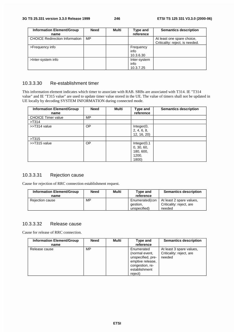
ETSI
ETSI TS 125 331 V3.3.0 (2000-06)2463G TS 25.331 version 3.3.0 Release 1999
Information Element/Groupname
Need Multi Type andreference
Semantics description
CHOICE Redirection Information MP At least one spare choice,Criticality: reject, is needed.
>Frequency info Frequencyinfo10.3.6.30
>Inter-system info Inter-systeminfo10.3.7.25
10.3.3.30 Re-establishment timer
This information element indicates which timer to associate with RAB. SRBs are associated with T314. IE "T314value" and IE "T315 value" are used to update timer value stored in the UE. The value of timers shall not be updated inUE locally by decoding SYSTEM INFORMATION during connected mode.
Information Element/Groupname
Need Multi Type andreference
Semantics description
CHOICE Timer value MP>T314>>T314 value OP Integer(0,
2, 4, 6, 8,12, 16, 20)
>T315>>T315 value OP Integer(0,1
0, 30, 60,180, 600,1200,1800)
10.3.3.31 Rejection cause
Cause for rejection of RRC connection establishment request.
Information Element/Groupname
Need Multi Type andreference
Semantics description
Rejection cause MP Enumerated(congestion,unspecified)
At least 2 spare values,Criticality: reject, areneeded
10.3.3.32 Release cause
Cause for release of RRC connection.
Information Element/Groupname
Need Multi Type andreference
Semantics description
Release cause MP Enumerated(normal event,unspecified, pre-emptive release,congestion, re-establishmentreject)
At least 3 spare values,Criticality: reject, areneeded

ETSI
ETSI TS 125 331 V3.3.0 (2000-06)2473G TS 25.331 version 3.3.0 Release 1999
10.3.3.33 RF capability
Information Element/Groupname
Need Multi Type andReference
Semantics description
CHOICE mode MP>FDD>>UE power class MP Enumerated(
1..4)as defined in 25.101subclause 6.2.1
>>Tx/Rx frequency separation MP Enumerated(190, 174.8-205.2,134.8-245.2)
In MHzas defined in 25.101subclause 5.3.NOTE: Not applicable if UE isnot operating in frequencyband a (as defined in 25.101).
At least 1 spare value needed>TDD>>UE power class MP Enumerated
(1..4)as defined in 25.102subclause 6.2.1
>>Radio frequency bands MP 1 to<maxFrequencybands>
Enumerated(a, b, c)
as defined in 25.102subclause 5.2
At least 1 spare value needed>>Chip rate capability MP Enumerated(
3.84Mcps,1.28Mcps)
as defined in 25.102
10.3.3.34 RLC capability
Information Element/Groupname
Need Multi Type andReference
Semantics description
Total RLC AM buffer size MP Integer(2,10,50,100,150,500,1000)
Total receiving andtransmitting RLC AM buffercapability in kBytesAt least 1 spare value needed
Maximum number of AM entities MP Integer(3,4,5,6,8,16,32)
At least 1 spare value needed
10.3.3.35 RLC reset indicator
This IE is used to re-configure AM RLC on c-plane and u-plane.
Information Element/Groupname
Need Multi Type andreference
Semantics description
RLC reset indicator MP Boolean TRUE means resetrequiredFALSE means reset notrequired
10.3.3.36 Security capability
Information Element/Groupname
Need Multi Type andreference
Semantics description
Ciphering algorithm capability MP Bit string(16) "00000000000000002": UEA0,no encryption supported;"00000000000000012": UEA1,Kasumi supported
Integrity protection algorithmcapability
MP Bit string(16) "00000000000000012": UEA1,Kasumi supported

ETSI
ETSI TS 125 331 V3.3.0 (2000-06)2483G TS 25.331 version 3.3.0 Release 1999
10.3.3.37 Transmission probability
NOTE: Only for FDD.
Indicates the probability for a mobile to be allowed to transmit on a DCH controlled by DRAC procedure.
Information Element/Groupname
Need Multi Type andreference
Semantics description
Transmission probability MP Real(0.125.. 1.0by step of 0.125)
probability

ETSI
ETSI TS 125 331 V3.3.0 (2000-06)2493G TS 25.331 version 3.3.0 Release 1999
10.3.3.38 Transport channel capability
Information Element/Groupname
Need Multi Type andReference
Semantics description
Downlink transport channelcapability informationelementsMax no of bits received MP Integer(640,
1280, 2560,3840, 5120,6400, 7680,8960, 10240,20480,40960,81920,163840)
Maximum sum of number ofbits of all transport blocksreceived in TTIs that endwithin the same arbitraryinterval of length T<10 ms
At least 3 spare values areneeded.
Max convolutionally coded bitsreceived
MP Integer(640,1280, 2560,3840, 5120,6400, 7680,8960, 10240,20480,40960,81920,163840)
Maximum sum of number ofbits of all convolutionallycoded transport blocksreceived in TTIs that endwithin the same arbitraryinterval of length T<10 ms
At least 3 spare values areneeded
Max turbo coded bits received CVturbo_dec_sup
Integer(640,1280, 2560,3840, 5120,6400, 7680,8960, 10240,20480,40960,81920,163840)
Maximum sum of number ofbits of all turbo coded transportblocks received in TTIs thatend within the same arbitraryinterval of length T<10 ms
At least 3 spare values areneeded
Maximum number ofsimultaneous transport channels
MP Integer(4, 8,16, 32)
Max no of received transportblocks
MP Integer(4, 8,16, 32, 48,64, 96, 128,256, 512)
Maximum total number oftransport blocks receivedwithin TTIs that end at withinthe same 10ms interval
At least 6 spare values neededMaximum number of TFC in theTFCS
MP Integer(16,32, 48, 64,96, 128, 256,512, 1024)
At least 7 spare values needed
Maximum number of TF MP Integer(32,64, 128, 256,512, 1024)
At least 2 spare values needed
Support for turbo decoding MP Boolean TRUE means supportedUplink transport channelcapability informationelementsMax no of bits transmitted MP Integer(640,
1280, 2560,3840, 5120,6400, 7680,8960, 10240,20480,40960,81920,163840)
Maximum sum of number ofbits of all transport blockstransmitted in TTIs that start atthe same time
At least 3 spare values needed

ETSI
ETSI TS 125 331 V3.3.0 (2000-06)2503G TS 25.331 version 3.3.0 Release 1999
Max convolutionally coded bitstransmitted
MP Integer(640,1280, 2560,3840, 5120,6400, 7680,8960, 10240,20480,40960,81920,163840)
Maximum sum of number ofbits of all convolutionallycoded transport blockstransmitted in TTIs that start atthe same time
At least 3 spare values needed
Max turbo coded bits transmitted CVturbo_enc_sup
Integer(640,1280, 2560,3840, 5120,6400, 7680,8960, 10240,20480,40960,81920,163840)
Maximum sum of number ofbits of all turbo coded transportblocks transmitted in TTIs thatstart at the same time
At least 3 spare values needed
Maximum number ofsimultaneous transport channels
MP Integer(2, 4,8, 16, 32)
At least 3 spare values needed
Max no of transmitted transportblocks
MP Integer(2, 4,8, 16, 32, 48,64, 96, 128,256, 512)
Maximum total number oftransport blocks transmittedwithin TTIs that start at thesame time
At least 5 spare values neededMaximum number of TFC in theTFCS
MP Integer(4, 8,16, 32, 48,64, 96, 128,256, 512,1024)
At least 5 spare values needed
Maximum number of TF MP Integer(32,64, 128, 256,512, 1024)
At least 2 spare values needed
Support for turbo encoding MP Boolean TRUE means supported
Condition Explanationturbo_dec_sup Presence is mandatory if IE Support of turbo
decoding = True. Otherwise this field is not needed inthe message.
turbo_enc_sup Presence is mandatory if IE Support of turboencoding = True. Otherwise this field is not needed inthe message.
10.3.3.39 UE multi-mode/multi-RAT capability
Information Element/Groupname
Need Multi Type andReference
Semantics description
Multi-RAT capabilitySupport of GSM MP BooleanSupport of multi-carrier MP BooleanMulti-mode capability MP Enumerated
(TDD, FDD,FDD/TDD)

ETSI
ETSI TS 125 331 V3.3.0 (2000-06)2513G TS 25.331 version 3.3.0 Release 1999
10.3.3.40 UE radio access capability
Information Element/Groupname
Need Multi Type andreference
Semantics description
ICS version MP Enumerated(R99)
Indicates the release versionof TS 34.123-2(Implementation ConformanceStatement (ICS) proformaspecification) that is applicablefor the UE..At least 7 spare values needed
PDCP capability MP PDCPcapability10.3.3.25
RLC capability MP RLCcapability10.3.3.34
Transport channel capability MP Transportchannelcapability10.3.3.38
RF capability MP RF capability10.3.3.33
Physical channel capability MP Physicalchannelcapability10.3.3.26
UE multi-mode/multi-RATcapability
MP UE multi-mode/multi-RATcapability10.3.3.39
Security capability MP Securitycapability10.3.3.36
LCS capability MP LCScapability10.3.3.19
CHOICE mode MP>FDD>>Measurement capability MP Measuremen
t capability10.3.3.21
>TDD (no data)
10.3.3.41 UE Timers and Constants in CELL_DCH
This information element specifies timer- and constant values used by the UE in state CELL_DCH.
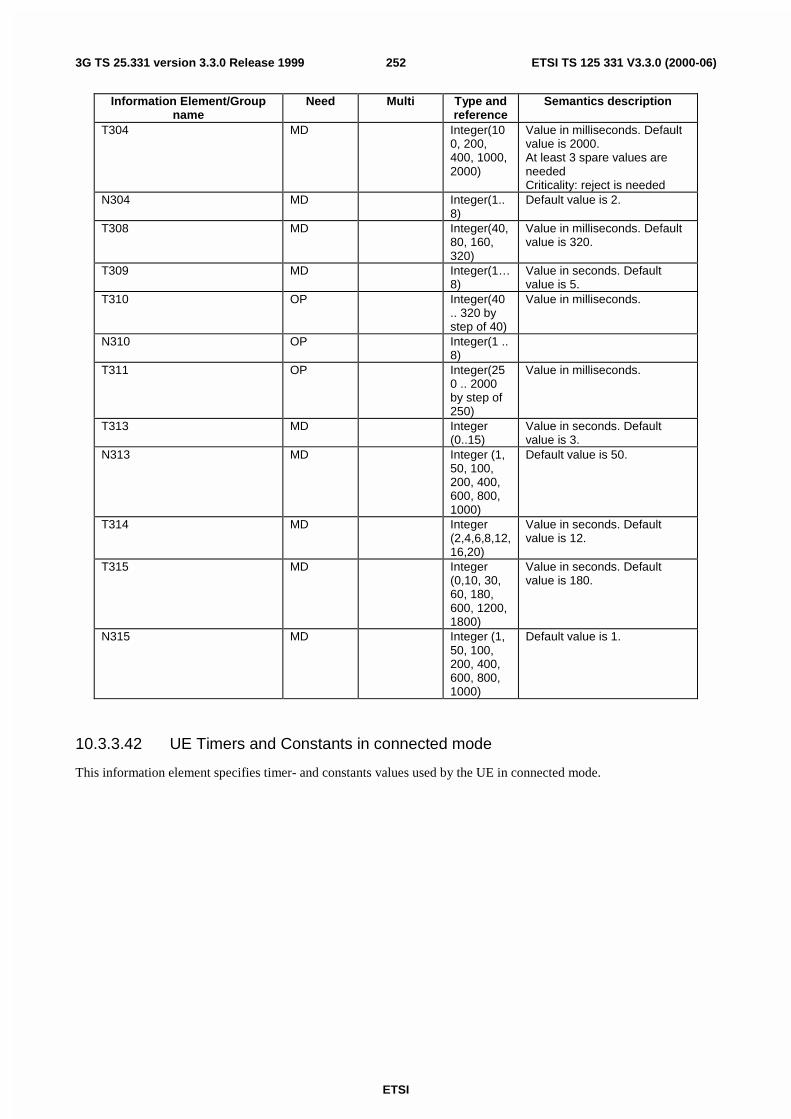
ETSI
ETSI TS 125 331 V3.3.0 (2000-06)2523G TS 25.331 version 3.3.0 Release 1999
Information Element/Groupname
Need Multi Type andreference
Semantics description
T304 MD Integer(100, 200,400, 1000,2000)
Value in milliseconds. Defaultvalue is 2000.At least 3 spare values areneededCriticality: reject is needed
N304 MD Integer(1..8)
Default value is 2.
T308 MD Integer(40,80, 160,320)
Value in milliseconds. Defaultvalue is 320.
T309 MD Integer(1…8)
Value in seconds. Defaultvalue is 5.
T310 OP Integer(40.. 320 bystep of 40)
Value in milliseconds.
N310 OP Integer(1 ..8)
T311 OP Integer(250 .. 2000by step of250)
Value in milliseconds.
T313 MD Integer(0..15)
Value in seconds. Defaultvalue is 3.
N313 MD Integer (1,50, 100,200, 400,600, 800,1000)
Default value is 50.
T314 MD Integer(2,4,6,8,12,16,20)
Value in seconds. Defaultvalue is 12.
T315 MD Integer(0,10, 30,60, 180,600, 1200,1800)
Value in seconds. Defaultvalue is 180.
N315 MD Integer (1,50, 100,200, 400,600, 800,1000)
Default value is 1.
10.3.3.42 UE Timers and Constants in connected mode
This information element specifies timer- and constants values used by the UE in connected mode.

ETSI
ETSI TS 125 331 V3.3.0 (2000-06)2533G TS 25.331 version 3.3.0 Release 1999
Information Element/Groupname
Need Multi Type andreference
Semantics description
T301 MD Integer(1...8)
Value in seconds. Defaultvalue is 1.
T302 MD Integer(1...8)
Value in seconds. Defaultvalue is 5.
N302 MD Integer(1..8)
Default value is 3.
T303 MD Integer(1...8)
Value in seconds. Defaultvalue is 8.
N303 MD Integer(1..8)
Default value is 3.
T304 MD Integer(100, 200,400, 1000,2000)
Value in milliseconds. Defaultvalue is 2000.At least 3 spare values areneededCriticality: reject is needed
N304 MD Integer(1..8)
Default value is 60.
T305 MD Integer(5,10, 30, 60,120, 360,720,infinity)
Value in minutes. Defaultvalue is 60.Infinity means no update
T306 MD Integer(5,10, 30, 60,120, 360,720,infinity)
Value in minutes. Defaultvalue is 60.Infinity means no update
T307 MD Integer(5,10, 15, 20,30, 40, 50)
Value in seconds. Defaultvalue is 30.At least 1 spare value neededCriticality: reject is needed
T308 MD Integer(40,80, 160,320)
Value in milliseconds. Defaultvalue is 320.
T309 MD Integer(1…8)
Value in seconds. Defaultvalue is 5.
T310 OP Integer(40.. 320 bystep of 40)
Value in milliseconds
N310 OP Integer(1 ..8)
T311 OP Integer(250 .. 2000by step of250)
Value in milliseconds
T312 MD Integer(0..15)
Value in seconds. Defaultvalue is 1.
N312 MD Integer (1,50, 100,200, 400,600, 800,1000)
Default value is 1.
T313 MD Integer(0..15)
Value in seconds. Defaultvalue is 3.
N313 MD Integer (1,50, 100,200, 400,600, 800,1000)
Default value is 50.
T314 OP Integer(0,2, 4, 6, 8,12, 16, 20)
Value in seconds. Defaultvalue is 12.

ETSI
ETSI TS 125 331 V3.3.0 (2000-06)2543G TS 25.331 version 3.3.0 Release 1999
T315 MD Integer(0,10, 30,60, 180,600, 1200,1800)
Value in seconds. Defaultvalue is 180.
N315 MD Integer (1,50, 100,200, 400,600, 800,1000)
Default value is 1.
10.3.3.43 UE Timers and Constants in idle mode
This information element specifies timer- and constant values used by the UE in idle mode.
Information Element/Groupname
Need Multi Type andreference
Semantics description
T300 MP Integer(1...8)
Value in seconds
N300 MP Integer(1..8)
T312 MP Integer(0 ..15)
Value in seconds
N312 MP Integer (1,50, 100,200, 400,600, 800,1000)
10.3.3.44 URA update cause
Indicates the cause for s URA update.
Information Element/Groupname
Need Multi Type andreference
Semantics description
URA update cause MP Enumerated(change of URA,periodic URAupdate, re-entered servicearea)
At least 5 spare valuesCriticality: reject, areneeded
10.3.3.45 U-RNTI
The U-RNTI (UTRAN Radio Network Temporary Identity) is allocated to an UE having a RRC connection andidentifies the UE within UTRAN.
Information Element/Groupname
Need Multi Type andreference
Semantics description
SRNC identity MP bit string(12)S-RNTI MP bit string(20)
10.3.3.46 U-RNTI Short
The U-RNTI (UTRAN Radio Network Temporary Identity) is allocated to an UE having a RRC connection andidentifies the UE within UTRAN.

ETSI
ETSI TS 125 331 V3.3.0 (2000-06)2553G TS 25.331 version 3.3.0 Release 1999
Information Element/Groupname
Need Multi Type andreference
Semantics description
SRNC identity MP bit string(12)S-RNTI 2 MP bit string(10)
10.3.3.47 UTRAN DRX cycle length coefficient
A coefficient in the formula to count the paging occasions to be used by a specific UE (specified in 25.304).
Information Element/Groupname
Need Multi Type andreference
Semantics description
DRX cycle length coefficient MP Integer(2...12) Refers to 'k' in the formulaas specified in 25.304,Discontinuous reception
10.3.3.48 Wait time
Wait time defines the time period the UE has to wait before repeating the rejected procedure.
Information Element/Groupname
Need Multi Type andreference
Semantics description
Wait time MP Integer(0..15)
Wait time in secondsThe value 0 indicates thatrepetition is not allowed.
10.3.4 Radio Bearer Information elements
10.3.4.1 Downlink RLC STATUS info
Information Element/Groupname
Need Multi Type andreference
Semantics description
Timer_Status_Prohibit OP Integer(10..550 by step of10)
Minimum time in ms betweenSTATUS reportsAt least 16 spare values withcriticality reject is needed
Timer_EPC OP Integer(50,60, 70, 80,90, 100, 120,140, 160,180, 200,300, 400,500, 700,900)
Time in msAt least 16 spare values withcriticality reject is needed
Missing PU Indicator MP Boolean Value true indicates that UEshould send a STATUS reportfor each missing PU that isdetected
Timer_STATUS_periodic OP Integer(100,200, 300,400, 500,750, 1000,2000)
Time in milliseconds

ETSI
ETSI TS 125 331 V3.3.0 (2000-06)2563G TS 25.331 version 3.3.0 Release 1999
10.3.4.2 PDCP info
The purpose of the PDCP info IE is to indicate which algorithms shall be established and to configure the parameters ofeach of the algorithms.
Information Element/Groupname
Need Multi Type andreference
Semantics description
Support for lossless SRNSrelocation
CV-LosslessCriteria
Boolean TRUE means support
Max PDCP SN CVLossless
Integer (255,65535)
Maximum PDCP sequencenumber. Default value is65535.
PDCP PDU header MD Enumerated(present,absent)
Whether a PDCP PDU headeris existent or not. Default valueis "present"
Header compression information OP 1 to<maxPDCPAlgoType>
>CHOICE algorithm type MP 7 spare values needed,criticality: reject
>>RFC2507 Header compressionaccording to IETF standardRFC2507
>>>F_MAX_PERIOD MD Integer(1..65535)
Largest number ofcompressed non-TCP headersthat may be sent withoutsending a full header. Defaultvalue is 256.
>>>F_MAX_TIME MD Integer(1..255)
Compressed headers may notbe sent more thanF_MAX_TIME seconds aftersending last full header.Default value is 5.
>>>MAX_HEADER MD Integer(60..65535)
The largest header size inoctets that may becompressed. Default value is168.
>>>TCP_SPACE MD Integer(3..255)
Maximum CID value for TCPconnections. Default value is15.
>>>NON_TCP_SPACE MD Integer(3..65535)
Maximum CID value for non-TCP connections. Defaultvalue is 15.
>>>EXPECT_REORDERING MD Enumerated(reorderingnotexpected,reorderingexpected)
Whether the algorithm shallreorder PDCP SDUs or not.Default value is "reordering notexpected".
Condition ExplanationLosslessCriteria This IE is present only if the IE "RLC mode" is
"Acknowledged" and the IE "In-sequence delivery " is"True".
Lossless This IE shall be present if the IE "Support for losslessSRNS relocation" Is TRUE, otherwise it shall beabsent.

ETSI
ETSI TS 125 331 V3.3.0 (2000-06)2573G TS 25.331 version 3.3.0 Release 1999
10.3.4.3 PDCP SN info
Information Element/Groupname
Need Multi Type andReference
Semantics description
Receive PDCP sequencenumber
MP Integer(0..65535)
The PDCP sequence numberwhich the sender of themessage is expecting next tobe received.
10.3.4.4 Polling info
Information Element/Groupname
Need Multi Type andreference
Semantics description
Timer_poll_prohibit OP Integer(50,60, 70, 80,90, 100, 120,140, 160,180, 200,300, 400,500, 700,900)
Minimum time between polls inms16 spare values needed,criticality: reject
Timer_poll OP Integer(10..550 by step of10,600..1000 bystep of 50)
Time in ms.16 spare values needed,criticality: reject
Poll_PU OP Integer(1,2,4,8,16,32,64,128)
Number of PUs, intervalbetween pollings8 spare values needed,criticality: reject
Poll_SDU OP Integer(1,4,16,64)
Number of SDUs, intervalbetween pollings4 spare values needed,criticality: reject
Last transmission PU poll MP Boolean TRUE indicates that poll ismade at last PU intransmission buffer
Last retransmission PU poll MP Boolean TRUE indicates that poll ismade at last PU inretransmission buffer
Poll_Window OP Integer(50,60,70,80,85,90,95,99)
Percentage of transmissionwindow, threshold for polling8 spare values needed,criticality: reject
Timer_poll_periodic OP Integer(100,200, 300,400, 500,750, 1000,2000)
Time in milliseconds Timer forperiodic polling.8 spare values needed,criticality: reject
10.3.4.5 Predefined configuration identity
This information element identifies a pre- defined radio parameter configuration.
Information Element/Groupname
Need Multi Type andreference
Semantics description
Predefined radio configurationidentity
MP Integer(0..15)

ETSI
ETSI TS 125 331 V3.3.0 (2000-06)2583G TS 25.331 version 3.3.0 Release 1999
10.3.4.6 Predefined configuration value tag
This information element is used to identify different versions of a radio bearer configuration as may be used within onePLMN e.g. to support different UTRAN implementations.
Information Element/Groupname
Need Multi Type andReference
Semantics description
Predefined configuration valuetag
MP Integer(0..15)
10.3.4.7 Predefined RB configuration
This information element concerns a pre- defined configuration of radio bearer parameters
Information Element/Groupname
Need Multi Type andReference
Semantics description
Signalling radio bearerinformationSignalling RB information tosetup List
MP 1 to<maxSRBsetup>
For each signalling radiobearer
>Signalling RB information tosetup
MP SignallingRBinformationto setup10.3.4.21
RB information Only one RAB supported>RB information to setup list MP 1 to
<maxRBcount>
RBinformationto setup10.3.4.17
>RB information to setup MP RBinformationto setup10.3.4.17
10.3.4.8 RAB info
This IE contains information used to uniquely identify a radio access bearer.
Information Element/Groupname
Need Multi Type andreference
Semantics description
RAB identity MP RAB identity10.3.1.14
CN domain identity MP CN domainidentity10.3.1.1
Re-establishment timer MP Re-establishment timer10.3.3.30

ETSI
ETSI TS 125 331 V3.3.0 (2000-06)2593G TS 25.331 version 3.3.0 Release 1999
10.3.4.9 RAB information for setup
Information Element/Groupname
Need Multi Type andreference
Semantics description
RAB info MP RAB info10.3.4.8
RB information to setup list MP 1 to<maxRBperRAB>
>RB information to setup MP RBinformationto setup10.3.4.17
10.3.4.10 RB activation time info
This IE contains the time, in terms of RLC sequence numbers, when a certain configuration shall be activated, for anumber of radio bearers.
Information Element/Groupname
Need Multi Type andreference
Semantics description
Radio bearer activation time OP 1 to<maxRB>
>RB identity MP RB identity10.3.4.13
>RLC sequence number MP Integer (0..4095)
RLC SN [TS 25.322]
10.3.4.11 RB COUNT-C MSB information
The MSB of the COUNT-C values of the radio bearer.
Information Element/Groupname
Needed Multi Type andreference
Semantics description
RB identity MP RB identity10.3.4.13
COUNT-C-MSB-uplink MP Integer (0..2^25-1)
25 MSBs from COUNT-Cassociated to this RB
COUNT-C-MSB-downlink MP Integer (0..2^25-1)
25 MSBs from COUNT-Cassociated to this RB
10.3.4.12. RB COUNT-C information
The COUNT-C values of the radio bearer.
Information Element/Groupname
Needed Multi Type andreference
Semantics description
RB identity MP RB identity10.3.4.13
COUNT-C-uplink MP Integer (0..2^32-1)
COUNT-C-downlink MP Integer (0..2^32-1)
10.3.4.13 RB identity
An identification number for the radio bearer affected by a certain message.

ETSI
ETSI TS 125 331 V3.3.0 (2000-06)2603G TS 25.331 version 3.3.0 Release 1999
Information Element/Groupname
Need Multi Type andreference
Semantics description
RB identity MP Integer(0..31)
Values 0-4 shall only be usedfor signalling radio bearers
10.3.4.14 RB information to be affected
Information Element/Groupname
Need Multi Type andreference
Semantics description
RB identity MP RB identity10.3.4.13
RB mapping info MP RB mappinginfo10.3.4.18
10.3.4.15 RB information to reconfigure
Information Element/Groupname
Need Multi Type andreference
Semantics description
RB identity MP RB identity10.3.4.13
PDCP info OP PDCP info10.3.4.2
PDCP SN info C PDCP PDCP SNinfo10.3.4.3
PDCP sequence number infofrom the network. Present onlyin case of lossless SRNSrelocation.
CHOICE RLC info type OP>RLC info RLC info
10.3.4.20RB mapping info OP RB mapping
info10.3.4.18
RB suspend/resume OP Enumerated(suspend,resume)
Condition ExplanationPDCP This IE is optional only if "PDCP info" is present.
Otherwise it is absent.
10.3.4.16 RB information to release
Information Element/Groupname
Need Multi Type andreference
Semantics description
RB identity MP RB identity10.3.4.13

ETSI
ETSI TS 125 331 V3.3.0 (2000-06)2613G TS 25.331 version 3.3.0 Release 1999
10.3.4.17 RB information to setup
Information Element/Groupname
Need Multi Type andreference
Semantics description
RB identity MP RB identity10.3.4.13
PDCP info OP PDCP info10.3.4.2
RLC info MP RLC info10.3.4.20
RB mapping info MP RB mappinginfo10.3.4.18
Multi Bound ExplanationMaxSetupRBcount The maximum number of RBs to setup.
NOTE This information element is included within IE "Predefined RB configuration"

ETSI
ETSI TS 125 331 V3.3.0 (2000-06)2623G TS 25.331 version 3.3.0 Release 1999
10.3.4.18 RB mapping info
A multiplexing option for each possible transport channel this RB can be multiplexed on.
Information Element/Groupname
Need Multi Type andreference
Semantics description
Information for each multiplexingoption
MP 1 to<maxRBMuxOptions>
>Number of RLC logicalchannels
CV-UL-RLC info
1 toMaxLoCHperRLC
1 or 2 logical channels perRLC entity or radio bearerRLC [TS 25.322]
>>RLC logical channel mappingindicator
CV-UL-RLCLogicalChannels
Boolean TRUE indicates that the firstlogical channel shall be usedfor data PDUs and the secondlogical channel shall be usedfor control PDUs.FALSE indicates that controland data PDUs can be sent oneither of the two logicalchannels.
>>Uplink transport channel type MP Enumerated(DCH,RACH,CPCH,USCH)
CPCH is FDD onlyUSCH is TDD only
>>ULTransport channel identity CV-UL-DCH
Transportchannelidentity10.3.5.18
This is the ID of a DCH thatthis RB could be mapped onto.
>>Logical channel identity OP Integer(1..15)
This parameter is used todistinguish logical channelsmultiplexed by MAC on atransport channel.
>>MAC logical channel priority MP Integer(1..8) This is priority between auser's different RBs (or logicalchannels). [25.321]
>>Logical channel max loss MD Integer(0,5,10,15,20,25,30,35,40,45,50,55,60,65,70,75,80,85,90,95,100)
The maximum fraction oftransport blocks (in percent)that may be blocked fortransmission in favour of lowerpriority data [25.321]. Defaultvalue is 0.
>Number of RLC logicalchannels
CV-DL-RLC info
1 to 2 1 or 2 logical channels perRLC entity or radio bearerRLC [TS 25.322]
>>Downlink transport channeltype
MP Enumerated(DCH,FACH,DSCH)
>>DL Transport channel identity CV-DL-DCH/DSCH
Transportchannelidentity10.3.5.18
>>Logical channel identity OP Integer(1..15)
16 is reserved

ETSI
ETSI TS 125 331 V3.3.0 (2000-06)2633G TS 25.331 version 3.3.0 Release 1999
Condition ExplanationUL-RLC info If "CHOICE Uplink RLC mode" in IE "RLC info" is
present this IE is MP. Otherwise the IE is not needed.DL-RLC info If "CHOICE Downlink RLC mode" in IE "RLC info" is
present this IE is MP. Otherwise the IE is not needed.UL-RLCLogicalChannels If "Number of RLC logical channels" in IE "RB
mapping info" is 2, in the uplink, then this is present.Otherwise this IE is not needed.
UL-DCH If IE "Uplink transport channel type" is equal to "DCH"this IE is MP. Otherwise the IE is not needed.
DL-DCH/DSCH If IE "Downlink transport channel type" is equal to"DCH" or "DSCH" this IE is MP. Otherwise the IE isnot needed.
10.3.4.19 RB with PDCP information
Information Element/Groupname
Need Multi Type andreference
Semantics description
RB identity MP RB identity10.3.4.13
PDCP SN info MP PDCP SNinfo 10.3.4.3
PDCP sequence number infofrom the UE for lossless SRNSrelocation.
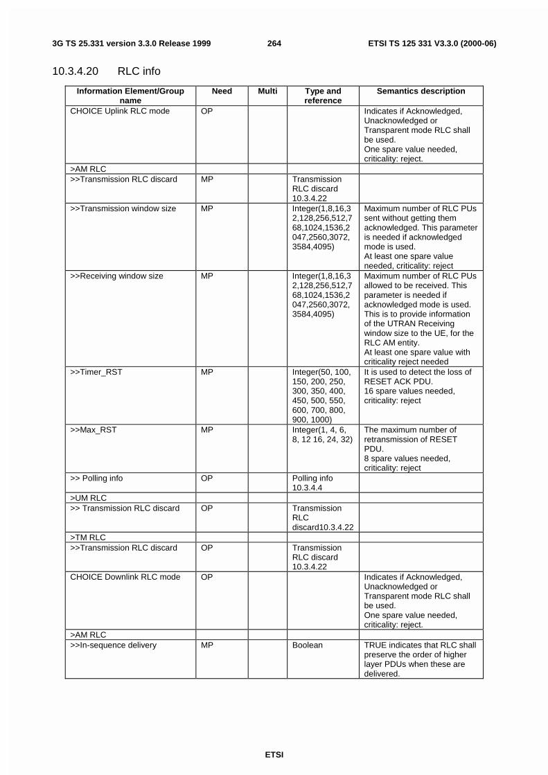
ETSI
ETSI TS 125 331 V3.3.0 (2000-06)2643G TS 25.331 version 3.3.0 Release 1999
10.3.4.20 RLC info
Information Element/Groupname
Need Multi Type andreference
Semantics description
CHOICE Uplink RLC mode OP Indicates if Acknowledged,Unacknowledged orTransparent mode RLC shallbe used.One spare value needed,criticality: reject.
>AM RLC>>Transmission RLC discard MP Transmission
RLC discard10.3.4.22
>>Transmission window size MP Integer(1,8,16,32,128,256,512,768,1024,1536,2047,2560,3072,3584,4095)
Maximum number of RLC PUssent without getting themacknowledged. This parameteris needed if acknowledgedmode is used.At least one spare valueneeded, criticality: reject
>>Receiving window size MP Integer(1,8,16,32,128,256,512,768,1024,1536,2047,2560,3072,3584,4095)
Maximum number of RLC PUsallowed to be received. Thisparameter is needed ifacknowledged mode is used.This is to provide informationof the UTRAN Receivingwindow size to the UE, for theRLC AM entity.At least one spare value withcriticality reject needed
>>Timer_RST MP Integer(50, 100,150, 200, 250,300, 350, 400,450, 500, 550,600, 700, 800,900, 1000)
It is used to detect the loss ofRESET ACK PDU.16 spare values needed,criticality: reject
>>Max_RST MP Integer(1, 4, 6,8, 12 16, 24, 32)
The maximum number ofretransmission of RESETPDU.8 spare values needed,criticality: reject
>> Polling info OP Polling info10.3.4.4
>UM RLC>> Transmission RLC discard OP Transmission
RLCdiscard10.3.4.22
>TM RLC>>Transmission RLC discard OP Transmission
RLC discard10.3.4.22
CHOICE Downlink RLC mode OP Indicates if Acknowledged,Unacknowledged orTransparent mode RLC shallbe used.One spare value needed,criticality: reject.
>AM RLC>>In-sequence delivery MP Boolean TRUE indicates that RLC shall
preserve the order of higherlayer PDUs when these aredelivered.

ETSI
ETSI TS 125 331 V3.3.0 (2000-06)2653G TS 25.331 version 3.3.0 Release 1999
>>Receiving window size MP Integer(1,8,16,32,128,256,512,768,1024,1536,2047,2560,3072,3584,4095)
Maximum number of RLC PUsallowed to be received. Thisparameter is needed ifacknowledged mode is used.At least one spare value withcriticality reject needed
>>Downlink RLC status Info MP Downlink RLCstatus info10.3.4.1
>UM RLC (No data)>TM RLC (No data)>>Segmentation indication MP Boolean TRUE indicates that
segmentation is performed.
NOTE This information element is included within IE "Predefined RB configuration"
10.3.4.21 Signalling RB information to setup
Information Element/Groupname
Need Multi Type andreference
Semantics description
RB identity MD RB identity10.3.4.13
Default value is the smallestvalue not yet used as defaultin the message (e.g., 0, then1, and so on)
CHOICE RLC info type MP>RLC info RLC info
10.3.4.20RB mapping info MP RB mapping
info10.3.4.18
NOTE This information element is included within IE "Predefined RB configuration"

ETSI
ETSI TS 125 331 V3.3.0 (2000-06)2663G TS 25.331 version 3.3.0 Release 1999
10.3.4.22 Transmission RLC Discard
Information Element/Groupname
Need Multi Type andreference
Semantics description
CHOICE SDU Discard Mode MP Different modes for dischargethe RLC buffer on thetransmitter side;"Timer based with explicitsignalling", "Timer basedwithout explicit signalling","Discard after Max_DATretransmissions" or"No_discard". Forunacknowledged mode andtransparent mode only Timerbased without explicitsignalling is applicable. If"No_discard" is used, resetprocedure shall be done afterMax_DAT retransmissions
>Timer based explicit>>Timer_MRW MP Integer(50,6
0, 70, 80, 90,100, 120,140, 160,180, 200,300, 400,500, 700,900)
It is used to trigger theretransmission of a STATUSPDU containing an MRW SUFIfield.16 spare values needed,criticality: reject
>>Timer_discard MP Integer(100,250, 500,750, 1000,1250, 1500,1750, 2000,2500, 3000,3500, 4000,4500, 5000,7500)
Elapsed time in milisecondsbefore a SDU is discarded.
>>MaxMRW MP Integer(1, 4,6, 8, 12 16,24, 32)
It is the maximum value for thenumber of retransmissions of aMRW command8 spare values needed,criticality: ffs
>Timer based no explicit>>Timer_discard MP Integer(10,2
0,30,40,50,60,70,80,90,100)
Elapsed time in milisecondsbefore a SDU is discarded.
>Max DAT retransmissions>> Max_DAT MP Integer(1, 2,
3, 4, 5, 6, 7,8, 9, 10, 15,20, 25, 30,35, 40)
Number of retransmissions ofa PU before a SDU isdiscarded.
>>Timer_MRW MP Integer(50,60, 70, 80,90, 100, 120,140, 160,180, 200,300, 400,500, 700,900)
It is used to trigger theretransmission of a STATUSPDU containing an MRW SUFIfield.16 spare values needed,criticality: reject
>>MaxMRW MP Integer(1, 4,6, 8, 12 16,24, 32)
It is the maximum value for thenumber of retransmissions of aMRW command8 spare values needed,criticality: ffs

ETSI
ETSI TS 125 331 V3.3.0 (2000-06)2673G TS 25.331 version 3.3.0 Release 1999
>No discard>> Max_DAT MP Integer(1, 2,
3, 4, 5, 6, 7,8, 9, 10, 15,20, 25, 30,35, 40)
Number of retransmissions ofa PU before a SDU isdiscarded.
CHOICE SDU Discard Mode Condition under which the given SDU DiscardMode is chosen
Timer based explicit If the modes for discharge of the RLC buffer on thetransmitter side is "Timer based with explicitsignalling"
Timer based no explicit If the modes for discharge of the RLC buffer on thetransmitter side is "Timer based without explicitsignalling"For unacknowledged mode, only Timer based withoutexplicit signalling is applicable.
Max DAT retransmissions If the modes for discharge of the RLC buffer on thetransmitter side is "Discard after Max_DATretransmissions"
No discard If the modes for discharge the of RLC buffer on thetransmitter side is "Reset procedure shall be doneafter Max_DAT retransmissions"
10.3.5 Transport CH Information elements
10.3.5.1 Added or Reconfigured DL TrCH information
Information Element/Groupname
Need Multi Type andreference
Semantics description
DL Transport channel identity MP Transportchannelidentity10.3.5.18
CHOICE DL parameters>Independent>>TFS MP Transport
Format Set10.3.5.23
>SameAsUL>>UL TrCH identity MP Transport
channelidentity10.3.5.18
Same TFS applies asspecified for indicated ULTrCH
DCH quality target OP Qualitytarget10.3.5.10
Transparent mode signalling info OP Transparentmodesignallinginfo10.3.5.17
This IE is not used in RBRELEASE message nor RBRECONFIGURATIONmessage

ETSI
ETSI TS 125 331 V3.3.0 (2000-06)2683G TS 25.331 version 3.3.0 Release 1999
10.3.5.2 Added or Reconfigured UL TrCH information
Information Element/Groupname
Need Multi Type andreference
Semantics description
UL Transport channel identity MP Transportchannelidentity10.3.5.18
TFS MP TransportFormat Set10.3.5.23
NOTE This information element is included within IE "Predefined RB configuration""
10.3.5.3 CPCH set ID
NOTE: Only for FDD.
This information element indicates that this transport channel may use any of the Physical CPCH channels defined inthe CPCH set info which contains the same CPCH set ID. The CPCH set ID associates the transport channel with a setof PCPCH channels defined in a CPCH set info IE and a set of CPCH persistency values. The CPCH set info IE(s) andthe CPCH persistency values IE(s) each include the CPCH set ID and are part of the SYSTEM INFORMATIONmessage
Information Element/Groupname
Need Multi Type andreference
Semantics description
CPCH set ID MP Integer(1...<maxCPCHsets>)
Identifier for CPCH set infoand CPCH persistency valuemessages
Multi Bound ExplanationMaxCPCHsets Maximum number of CPCH sets per Node B
10.3.5.4 Deleted DL TrCH information
Information Element/Groupname
Need Multi Type andreference
Semantics description
DL Transport channel identity MP Transportchannelidentity10.3.5.18
10.3.5.5 Deleted UL TrCH information
Information Element/Groupname
Need Multi Type andreference
Semantics description
UL Transport channel identity MP Transportchannelidentity10.3.5.18

ETSI
ETSI TS 125 331 V3.3.0 (2000-06)2693G TS 25.331 version 3.3.0 Release 1999
10.3.5.6 DL Transport channel information common for all transport channels
Information Element/Groupname
Need Multi Type andreference
Semantics description
SCCPCH TFCS OP TransportFormatCombinationSet10.3.5.20
This IE should be absentwithin IE "Predefined RBconfiguration"
CHOICE mode OP>FDD>>CHOICE DL parameters MP>>>Independent>>>>DL DCH TFCS OP Transport
FormatCombinationSet10.3.5.20
>>>SameAsUL (no data)>TDD>>Individual DL CCTrCHinformation
OP 1 to>maxCCTrCH>
>>>DL TFCS Identity MP Transportformatcombinationset identity10.3.5.21
Identifies a special CCTrCHfor shared or dedicatedchannels.
>>>CHOICE DL parameters MP>>>>Independent>>>>>DL TFCS MP Transport
formatcombinationset 10.3.5.20
>>>>SameAsUL>>>>>UL DCH TFCS Identity MP Transport
formatcombinationset identity10.3.5.21
Same TFCS applies asspecified for the indicated ULDCH TFCS identity except forinformation applicable for ULonly
NOTE This information element is included within IE "Predefined TrCh configuration"
10.3.5.7 DRAC Static Information
NOTE: Only for FDD.
Contains static parameters used by the DRAC procedure. Meaning and use is described in subclause 14.6.
Information Element/Groupname
Need Multi Type andreference
Semantics description
Transmission Time Validity MP Integer(1..256) number of framesTime duration before retry MP Integer(1..256) number of framesDRAC Class Identity MP Integer(1..8) Indicates the class of
DRAC parameters to usein SIB10 message

ETSI
ETSI TS 125 331 V3.3.0 (2000-06)2703G TS 25.331 version 3.3.0 Release 1999
10.3.5.8 Power Offset Information
Information Element/Groupname
Need Multi Type andreference
Semantics description
CHOICE Gain Factors MP>Signalled Gain Factors>>Gain Factor βc MP Integer
(0.. 15)For UL DPCCH or control partof PRACH or PCPCH
>>Gain Factor βd MP Integer(0..15)
For UL DPDCH or data part ofPRACH or PCPCH
>>Reference TFC ID OP Integer (0..3) If this TFC is a reference TFC,indicates the reference ID.
>Computed Gain Factors>>Reference TFC ID MP Integer
(0.. 3)Indicates the reference TFC Idof the TFC to be used tocalculate the gain factors forthis TFC. In case of usingcomputed gain factors, at leastone signalled gain factor isnecessary for reference.
Power offset P p-m OP Integer(-5..10)
In dB. Power offset betweenthe last transmitted preambleand the control part of themessage (added to thepreamble power to receive thepower of the message controlpart )Needed only for PRACH
CHOICE Gain Factors Condition under which the way to signal the GainFactors is chosen
Signalled Gain Factors The values for gain factors βc and βd aresignalled directly for a TFC.
Computed Gain Factors The gain factors βc and βd are computed for aTFC, based on the signalled settings for theassociated reference TFC.
10.3.5.9 Predefined TrCH configuration
This information element concerns a pre- defined configuration of transport channel parameters.

ETSI
ETSI TS 125 331 V3.3.0 (2000-06)2713G TS 25.331 version 3.3.0 Release 1999
Information Element/Groupname
Need Multi Type andReference
Semantics description
UL Transport channelinformation common for alltransport channels
MP UL Transportchannelinformationcommon forall transportchannels10.3.5.24
Added or Reconfigured TrCH informationAdded or Reconfigured UL TrCHinformation
MP 1 to<maxTrCHpreconf>
>Added or Reconfigured ULTrCH information
MP Added orReconfigured UL TrCHinformation10.3.5.2
DL Transport channelinformation common for alltransport channels
MP DL Transportchannelinformationcommon forall transportchannels10.3.5.6
Downlink transport channelsAdded or Reconfigured DL TrCHinformation
MP 1 to<maxTrCHpreconf>
>Added or Reconfigured DLTrCH information
MP Added orReconfigured DL TrCHinformation10.3.5.1
10.3.5.10 Quality Target
Information Element/Groupname
Need Multi Type andreference
Semantics description
BLER Quality value MP Real(0.00..1.00, by step of 0.02)
In dB=-Log10(Transport channelBLER)

ETSI
ETSI TS 125 331 V3.3.0 (2000-06)2723G TS 25.331 version 3.3.0 Release 1999
10.3.5.11 Semi-static Transport Format Information
Information Element/Groupname
Need Multi Type andreference
Semantics description
Transmission time interval MP Integer(10,20, 40, 80,dynamic)
In ms. The value dynamic isonly used in TDD mode3 spare values are neededCriticality reject
Type of channel coding MP Enumerated(No coding,Convolutional, Turbo)
Coding Rate CV-Coding Enumerated(1/2, 1/3)
Rate matching attribute MP Integer(1..hiRM)
CRC size MP Integer(0, 8,12, 16, 24)
in bits
Condition ExplanationCoding This IE is only present if IE "Type of channel coding"
is "Convolutional"
10.3.5.12 TFCI Field 2 Information
UTRAN has the choice of two methods for signalling the mapping between TFCI (field 2) values and the correspondingTFC:

ETSI
ETSI TS 125 331 V3.3.0 (2000-06)2733G TS 25.331 version 3.3.0 Release 1999
Method #1 - TFCI range
The mapping is described in terms of a number of groups, each group corresponding to a given transport formatcombination (value of CTFC(field2)). The CTFC(field2) value specified in the first group applies for all values ofTFCI(field 2) between 0 and the specified 'Max TFCI(field2) value'. The CTFC(field2) value specified in the secondgroup applies for all values of TFCI(field 2) between the 'Max TFCI(field2) value' specified in the last group plus oneand the specified 'Max TFCI(field2) value' in the second group. The process continues in the same way for thefollowing groups with the TFCI(field 2) value used by the UE in constructing its mapping table starting at the largestvalue reached in the previous group plus one. A range of TFCI values on the transport channel level can be configuredto correspond to a range of codes in PDSCH mapping table.
Method #2 - Explicit
The mapping between TFCI(field 2) value and CTFC(field2) is spelt out explicitly for each value of TFCI (field2).
Information Element/Groupname
Need Multi IE type andreference
Semantics description
CHOICE Signalling method MP> TFCI range>> TFCI(field 2) range MP 1 to
<maxPDSCH-TFCIgroups>
>>>Max TFCI(field2) value MP Integer(1..1023)
This is the Maximum value inthe range of TFCI(field2)values for which the specifiedCTFC(field2) applies
>>>TFCS Information for DSCH(TFCI range method)
MP TFCSInformationfor DSCH(TFCI rangemethod)10.3.5.14
> Explicit>>TFCS explicit configuration MP TFCS
explicitconfiguration10.3.5.13
CHOICE Signalling method Condition under which Split type is chosenTFCI rangeExplicit
10.3.5.13 TFCS Explicit Configuration
Information Element/Groupname
Need Multi IE type andreference
Semantics description
CHOICE TFCS representation MP>Complete reconfiguration>>TFCS completereconfiguration information
MP TFCSRecofiguration/Additioninformation10.3.5.15
>Addition>> TFCS addition information MP TFCS
Reconfiguration/Additioninformation10.3.5.15
>Removal

ETSI
ETSI TS 125 331 V3.3.0 (2000-06)2743G TS 25.331 version 3.3.0 Release 1999
>> TFCS removal information MP TFCSRemovalInformation10.3.5.16
>Replace>> TFCS removal information MP TFCS
RemovalInformation10.3.5.16
>> TFCS addition information MP TFCSReconfiguration/Additioninformation10.3.5.15
10.3.5.14 TFCS Information for DSCH (TFCI range method)
The CTFC size should be chosen based on the maximum CTFC size for the UE. Integer number calculated according toclause 14. The calculation of CTFC ignores any DCH transport channels which may be assigned.
Information Element/Groupname
Need Multi IE type andreference
Semantics description
CHOICE CTFC Size MP At least one, criticality: reject,spare value needed for futureextension
>2 bit CTFC>>2bit CTFC MP Integer(0..3)>4 bit CTFC>>4bit CTFC MP Integer(0..15
)>6 bit CTFC>>6 bit CTFC MP Integer(0..63
)>8 bit CTFC>>8 bit CTFC MP Integer(0..25
5)>12 bit CTFC>>12 bit CTFC MP Integer(0..40
95)>16 bit CTFC>>16 bit CTFC MP Integer(0..65
535)>24 bit CTFC>>24 bit CTFC MP Integer(0..16
777215)
10.3.5.15 TFCS Reconfiguration/Addition Information
When it is used in TFCI field 1, the calculation of CTFC ignores any DSCH transport channels which may beassigned.When it is used in TFCI field 2, the calculation of CTFC ignores any DCH transport channels.
The CTFC size should be chosen based on the maximum CTFC size for the UE. The first instance of the parameter"CTFC information" corresponds to Transport format combination 0, the second to transport format combination 1 andso on when it is used besides the case of TFCS Addition. Integer number of CTFC calculated according to clause 14.
In case of TFCS Addition, the integer number(s) is the CTFC that is added. The new additional TFC(s) is inserted intothe first available position(s) in the TFCI. CTFC size should be same as the size used in Complete reconfiguration.

ETSI
ETSI TS 125 331 V3.3.0 (2000-06)2753G TS 25.331 version 3.3.0 Release 1999
Information Element/Groupname
Need Multi IE type andreference
Semantics description
CHOICE CTFC Size MP At least one, criticality: reject,spare value needed for futureextension
>2 bit CTFC>>CTFC information MP 1 to
<maxTFC>>>>2bit CTFC MP Integer(0..3)>>>Power offset Information OP Power Offset
Information10.3.5.8
Needed only for uplinkDPCCH/DPDCH or PRACH.
>4 bit CTFC>>CTFC information MP 1 to
<maxTFC>>>>4bit CTFC MP Integer(0..15
)>>>Power offset Information OP Power Offset
Information10.3.5.8
Needed only for uplinkDPCCH/DPDCH or PRACH.
>6 bit CTFC>>CTFC information MP 1 to
<maxTFC>>>>6 bit CTFC MP Integer(0..63
)>>>Power offset Information OP Power Offset
Information10.3.5.8
Needed only for uplinkDPCCH/DPDCH or PRACH.
>8 bit CTFC>>CTFC information MP 1 to
<MaxTFC>>>>8 bit CTFC MP Integer(0..25
5)>>>Power offset Information OP Power Offset
Information10.3.5.8
Needed only for uplinkDPCCH/DPDCH or PRACH.
>12 bit CTFC>>CTFC information MP 1 to
<maxTFC>>>>12 bit CTFC MP Integer(0..40
95)>>>Power offset Information OP Power Offset
Information10.3.5.8
Needed only for uplinkDPCCH/DPDCH or PRACH.
>16 bit CTFC>>CTFC information MP 1 to
<maxTFC>>>>16 bit CTFC MP Integer(0..65
535)>>>Power offset Information OP Power Offset
Information10.3.5.8
Needed only for uplinkDPCCH/DPDCH or PRACH.
>24 bit CTFC>>CTFC information MP 1 to
<MaxTFC>>>>24 bit CTFC MP Integer(0..16
777215)>>>Power offset Information OP Power Offset
Information10.3.5.8
Needed only for uplinkDPCCH/DPDCH or PRACH.

ETSI
ETSI TS 125 331 V3.3.0 (2000-06)2763G TS 25.331 version 3.3.0 Release 1999
10.3.5.16 TFCS Removal Information
The integer number(s) is a reference to the transport format combinations to be removed.
Information Element/Groupname
Need Multi IE type andreference
Semantics description
Removal TFCI information MP 1 to<maxTFC>
>TFCI MP Integer(0..1023)
Range Bound ExplanationMaxDelTFCcount Maximum number of Transport Format Combinations
to be removed.
10.3.5.17 Transparent mode signalling info
This information element points out a transport channel that is used for transparent mode signalling, and which type ofmessage that is sent on the DCCH mapped on that channel.
There are two modes of this transparent mode signaling. Mode 1 controls all transport channels for one UE. Mode 2only control a subset of the transport channels for one UE.
Information Element Need Multi Type andreference
Semantics description
Type of message MP Enumerated(TRANSPORTFORMATCOMBINATIONCONTROL)
Indicates which type ofmessage sent on thetransparent mode signallingDCCHAt least 1 spare valueneededCriticality: criticality reject isneeded
CHOICE Transparent signallingmode
MP
>Mode 1 (no data)
>Mode 2>>Controlled transport channelslist
MP 1 to<maxTrCH>
The transport channels thatare effected by the ratecontrol commands sent onthis transparent mode DCCH
>>>UL Controlled transportchannels
MP Transportchannel identity,10.3.5.18
10.3.5.18 Transport channel identity
This information element is used to distinguish transport channels. Transport channels of different type (RACH, CPCH,USCH, FACH/PCH, DSCH or DCH) have separate series of identities. This also holds for uplink and downlinktransport channel identities (i.e. for DCH). Depending on in which context a transport channel identity n that is sent, itwill have different meaning
Information Element/Groupname
Need Multi Type andreference
Semantics description
Transport channel identity MP Integer(1..32)

ETSI
ETSI TS 125 331 V3.3.0 (2000-06)2773G TS 25.331 version 3.3.0 Release 1999
10.3.5.19 Transport Format Combination (TFC)
Information Element/Groupname
Need Multi Type andreference
Semantics description
Transport format combination MP Integer (0..1023)
10.3.5.20 Transport Format Combination Set
Indicates the allowed combinations of already defined Transport formats and the mapping between these allowed TFCsand the corresponding TFCI values.
For TDD, different coded composite transport channels have independent transport format combination sets and thusindependent TFCI values.
For FDD, Where the UE is assigned access to one or more DSCH transport channels, a TFCI(field2) is used to signalthe transport format combination for the DSCH. The following two cases exist:
- Case 1:Using one TFCI-word on the physical layer. A logical split determines the available number of transport formatcombinations for DCH and DSCH.
- Case 2:Using split TFCI on the physical layer. Two TFCI-words, each having a static length of five bits, are used.

ETSI
ETSI TS 125 331 V3.3.0 (2000-06)2783G TS 25.331 version 3.3.0 Release 1999
Information Element/Groupname
Need Multi IE type andreference
Semantics description
CHOICE TFCI signalling MP 'Normal' : meaning no split inthe TFCI field (either 'Logical'or 'Hard')'Split' : meaning there is a splitin the TFCI field (either'Logical' or 'Hard'). This valueis only valid for FDD downlinkwhen using DSCH.
> Normal>> TFCI Field 1 Information MP TFCS
explicitConfiguration 10.3.5.13
> Split>> Split type OP Enumerated
('Hard','Logical')
'Hard' : meaning that TFCI(field 1) and TFCI (field 2) areeach 5 bits long and each fieldis block coded separately.'Logical' : meaning that on thephysical layer TFCI (field 1)and TFCI (field 2) areconcatenated, field 1 takingthe most significant bits andfield 2 taking the leastsignificant bits). The whole isthen encoded with a singleblock code.
>> Length of TFCI(field2) OP Integer(1..10)
This IE indicates the lengthmeasured in number of bits ofTFCI(field2)
>> TFCI Field 1 Information OP TFCSexplicitConfiguration 10.3.5.13
>> TFCI Field 2 Information OP TFCI field 2information10.3.5.12
CHOICE TFCI signalling Condition under which TFCI signalling type ischosen
Normal It is chosen when no split in the TFCI field.Split It is chosen when split in the TFCI field. This value is
only valid for FDD downlink when using DSCH.
10.3.5.21 Transport Format Combination Set Identity
NOTE: Only for TDD.
Information Element/Groupname
Need Multi Type andreference
Semantics description
TFCS ID MD Integer(1...8)
Indicates the identity of everyTFCS within a UE. Defaultvalue is 1.
Shared Channel Indicator MP Boolean TRUE indicates the use ofshared channels. Default isfalse.

ETSI
ETSI TS 125 331 V3.3.0 (2000-06)2793G TS 25.331 version 3.3.0 Release 1999
10.3.5.22 Transport Format Combination Subset
Indicates which Transport format combinations in the already defined Transport format combination set are allowed.
Information Element/Groupname
Need Multi Type andreference
Semantics description
CHOICE Subset representation MP>Minimum allowed Transportformat combination index
MP Transportformatcombination10.3.5.19
The integer number is areference to the Transportformat combination, whicharrived at that position in theTransport Format CombinationSet.
>Allowed transport formatcombination list
MP 1 to<maxTFC>
>>Allowed transport formatcombination
MP Transportformatcombination10.3.5.19
The integer number is areference to the Transportformat combination, whicharrived at that position in theTransport Format CombinationSet.
>Non-allowed transport formatcombination list
MP 1 to<maxTFC>
>>Non-allowed transport formatcombination
MP Transportformatcombination10.3.5.19
The integer number is areference to the Transportformat combination, whicharrived at that position in theTransport Format CombinationSet.
>Restricted TrCH information MP 1 to<maxTrCH>
>>Restricted UL TrCH identity MP Transportchannelidentity10.3.5.18
The integer number(s) is areference to the transportchannel that is restricted.
>>Allowed TFIs OP 1 to<maxTF>
>>>Allowed TFI MP Integer(0..31)
The integer number is areference to the transportformat that is allowed. If noelements are given, alltransport formats or the TrCHwith non-zero rate arerestricted.

ETSI
ETSI TS 125 331 V3.3.0 (2000-06)2803G TS 25.331 version 3.3.0 Release 1999
10.3.5.23 Transport Format Set
Information Element/Groupname
Need Multi Type andreference
Semantics description
CHOICE Transport channel type MP>Dedicated transport channels The transport channel that is
configured with this TFS is oftype DCH
>>Dynamic Transport FormatInformation
MP 1 to<maxTF>
The first instance of theparameter Dynamic transportformat information correspondto Transport format 0 for thistransport channel, the secondto transport format 1 and soon.
>>>Transmission Time Interval CV-dynamicTTI
Integer(10,20,40,80)
ms4 spare values are neededCriticality reject
>>>Number of Transport blocks MP Integer(0..512)
Note
>>>RLC Size MP Integer(0..4992)
Unit is bits
>>Semi-static Transport FormatInformation
MP Semi-staticTransportFormatInformation10.3.5.11
>Common transport channels The transport channel that isconfigured with this TFS is of atype not equal to DCH
>>Dynamic Transport FormatInformation
MP 1 to<maxTF>
The first instance of theparameter Dynamic transportformat information correspondto Transport format 0 for thistransport channel, the secondto transport format 1 and soon.
>>>Number of Transport blocks MP Integer(0..512)
Note
>>>RLC Size MP Integer(0..4992)
Unit is bits
>>>CHOICE mode MP>>>>FDD (no data)>>>>TDD>>>>> Transmission TimeInterval
CV-dynamicTTI
Integer(10,20,40,80)
ms4 spare values needed.Criticality reject
>>Semi-static Transport FormatInformation
MP Semi-staticTransportFormatInformation10.3.5.11
Condition ExplanationdynamicTTI This IE is included if dynamic TTI usage is indicated
in IE Transmission Time Interval in Semi-staticTransport Format Information. Otherwise it is notneeded.
NOTE: The parameter "rate matching attribute" is in line with the RAN WG1 specifications. However, it is notcurrently in line with the description in 25.302.

ETSI
ETSI TS 125 331 V3.3.0 (2000-06)2813G TS 25.331 version 3.3.0 Release 1999
NOTE: For dedicated channels, 'RLC size' reflects RLC PDU size. In FDD for common channels 'RLC size'reflects actual TB size. In TDD for common channels since MAC headers are not octet aligned, tocalculate TB size the MAC header bit offset is added to the specified size (similar to the dedicated case).Therefore for TDD DCH TrCHs the 4 bit C/T is added if MAC multiplexing is applied, for FACH the 3bit TCTF offset is added and for RACH the 2 bit TCTF offset is added.
NOTE: If the number of transport blocks <> 0, and Optional IE "CHOICE RLC mode" or "CHOICE Transportblock size is absent, it implies that no RLC PDU data exists but only parity bits exist. If the number oftransport blocks = 0, it implies that neither RLC PDU data nor parity bits exist.
10.3.5.24 UL Transport channel information common for all transport channels
Information Element/Groupname
Need Multi Type andreference
Semantics description
TFC subset MD TransportFormatCombinationSubset10.3.5.22
Default value is the completeexisting set of transport formatcombinations
CHOICE mode OP>FDD>>UL DCH TFCS MP Transport
formationcombinationset 10.3.5.20
>TDD>>Individual UL CCTrCHinformation
OP 1 to<maxCCTrCH>
>>>UL TFCS Identity MP Transportformatcombinationset identity10.3.5.21
Identifies a special CCTrCHfor shared or dedicatedchannels.
>>>UL TFCS MP Transportformatcombinationset 10.3.5.20
NOTE This information element is included within IE "Predefined TrCh configuration"
10.3.6 Physical CH Information elements
10.3.6.1 AC-to-ASC mapping
Information Element/Groupname
Need Multi Type andreference
Semantics description
AC-to-ASC mapping table MP maxASCmap
> AC-to-ASC mapping MP Integer(0…7)
Mapping of Access Classes toAccess Service Classes (cf.Sec. 8.5.15.)
10.3.6.2 AICH Info
NOTE: Only for FDD.

ETSI
ETSI TS 125 331 V3.3.0 (2000-06)2823G TS 25.331 version 3.3.0 Release 1999
Information Element/Groupname
Need Multi Type andreference
Semantics description
Secondary scrambling code MD Secondaryscramblingcode10.3.6.64
Default is the same scramblingcode as for the Primary CPICH
Channelisation code MP Integer(0..255)
SF is fixed and equal to 256
STTD indicator MP STTDIndicator10.3.6.68
AICH transmission timing MP Enumerated(0, 1)
See parameterAICH_Transmission_Timing inTS 25.211
10.3.6.3 AICH Power offset
NOTE: Only for FDD.
This is the power per transmitted Acquisition Indicator minus power of the Primary CPICH.
Information Element/Groupname
Need Multi Type andreference
Semantics description
AICH Power offset MP Integer(-10..+5)
Offset in dB
10.3.6.4 Allocation period info
NOTE: Only for TDD.
Parameters used by UE to determine period of shared channel allocation.
Information Element/Groupname
Need Multi Type andreference
Semantics description
Allocation Activation Time MP Integer(1..256)
Frame number start of theallocation period.
Allocation Duration MP Integer(1..256)
Total number of frames for theallocation period.
10.3.6.5 Block STTD indicator
NOTE: Only for TDD
Information Element/Groupname
Need Multi Type andreference
Semantics description
Block STTD indicator MP Boolean TRUE indicates that blockSTTD is used

ETSI
ETSI TS 125 331 V3.3.0 (2000-06)2833G TS 25.331 version 3.3.0 Release 1999
10.3.6.6 CCTrCH power control info
Parameters used by UE to set the SIR target value for uplink open loop power control in TDD.
Information Element/Groupname
Need Multi Type andReference
Semantics description
TFCS Identity OP TransportFormatCombinationSet Identity10.3.5.21
TFCS Identity of this CCTrCH.Default value is 1.
Uplink DPCH power control info MP UplinkDPCH powercontrol info10.3.6.79
10.3.6.7 Common timeslot info
Information Element/Groupname
Need Multi Type andreference
Semantics description
2nd interleaving mode MD Enumerated(Frame,Timeslot)
Frame timeslot relatedinterleaving. Default value is"Frame"
TFCI coding MD Integer(4,8,16,32)
Describes the way the TFCIbits are coded in bits.Defaults is no TFCI bit:4 means1 TFCI bit is coded with 4 bits.8 means2 TFCI bits are coded with 8bits.16 means3 – 5 TFCI bits are coded with16 bits.32 means6 – 10 TFCI bits coded with 32bits.
Puncturing limit MP Real(0.40..1.0 by step of0.04)
Repetition period MD Integer(1,2,4,8,16,32,64)
Default is continuousallocation. Value 1 indicatecontinuous
Repetition length MP Integer(1..Repetitionperiod –1 )
Note that this is empty ifrepetition period is set to 1
10.3.6.8 Constant value
This constant value is used by the UE to calculate the initial output power on PRACH according to the Open looppower control procedure.
Information Element/Groupname
Need Multi Type andreference
Semantics description
Constant value MP Integer (-10..10)
At least 11 spare valuesneededCriticality: reject is needed
10.3.6.9 CPCH persistence levels
NOTE: Only for FDD.

ETSI
ETSI TS 125 331 V3.3.0 (2000-06)2843G TS 25.331 version 3.3.0 Release 1999
This IE is dynamic and is used by RNC for load balancing and congestion control. This is broadcast often in the systeminformation message.
Information Element/Groupname
Need Multi Type andreference
Semantics description
CPCH set ID MP Integer (1 ..<maxCPCHsets>)
Identifier for CPCH set info.
Dynamic persistence level MP 1 to<maxTF-CPCH>
Dynamicpersistencelevel10.3.6.29
Persistence level for transportformat.

ETSI
ETSI TS 125 331 V3.3.0 (2000-06)2853G TS 25.331 version 3.3.0 Release 1999
10.3.6.10 CPCH set info
NOTE: Only for FDD.
This IE may be broadcast in the System Information message or assigned by SRNC. It is pseudo-static in a cell.
Information Element/Groupname
Need Multi Type andreference
Semantics description
CPCH set ID MP CPCH set ID10.3.5.3
Indicates the ID number for aparticular CPCH set allocatedto a cell.
TFS MP TransportFormat Set10.3.5.23
Transport Format SetInformation allocated to thisCPCH set.
TFCS MP TransportFormatCombinationSet10.3.5.20
Transport Format SetInformation allocated to thisCPCH set
AP preamble scrambling code MP Integer(0..79)
Preamble scrambling code forAP in UL
AP-AICH scrambling code MP SecondaryScramblingCode10.3.6.64
Default is the same scramblingcode as for the primaryCPICH.
AP-AICH channelisation code MP Integer(0..255)
Channelisation code for AP-AICH in DL
CD preamble scrambling code MP Integer(0..79)
Preamble scrambling code forCD in UL
CD/CA-ICH scrambling code MD SecondaryScramblingCode10.3.6.64
Default is the same scramblingcode as for the primaryCPICH.
CD/CA-ICH channelisation code MP Integer(0..255)
Channelisation code forCD/CA-ICH in DL
Available CD access slotsubchannel
CV-CDSigPresent
1 to<maxPCPCH-CDsubCh>
Lists the set of subchannels tobe used for CD accesspreambles. Note: if notpresent, all subchannels are tobe used without accessdelays.
>CD access slot subchannel MP Integer(0..11)
Available CD signatures OP 1 to<maxPCPCH-CDsig>
Signatures for CD preamble inUL. Note: if not present, allsignatures are available foruse.
>CD signatures MP Integer(0..15)
DeltaPp-m MP Integer (-10..10)
In dB. Power offset betweenthe transmitted CD preambleand UL DPCCH of the powercontrol preamble or messagepart (added to the preamblepower to calculate the powerof the UL DPCCH )
UL DPCCH Slot Format MP Enumerated(0,1,2)
Slot format for UL DPCCH inpower control preamble and inmessage part
N_start_message MP Integer (1..8) Number of Frames for start ofmessage indication

ETSI
ETSI TS 125 331 V3.3.0 (2000-06)2863G TS 25.331 version 3.3.0 Release 1999
N_EOT MP Integer(0...7) Actual number of appendedEOT indicators is T_EOT =N_TTI * ceil(N_EOT/N_TTI),where N_TTI is the number offrames per TTI and "ceil"refers to rounding up tonearest integer.
Channel Assignment Active OP Boolean When present, indicates thatNode B send a CA messageand VCAM mapping rule(14.11) shall be used.
CPCH status indication mode MP Enumerated(PCPCHavailability,PCPCHavailabilityandminimumavailableSpreadingFactor)
Defines the status informationtype broadcast on the CPCHStatus Indication Channel(CSICH)
PCPCH Channel Info. MP 1 to<maxPCPCHs>
> UL scrambling code MP Integer(0..79)
For PCPCH message part
> DL channelisation code MP Integer(0…511)
For DL DPCCH for PCPCHmessage part
> DL scrambling code MD SecondaryScramblingCode10.3.6.64
Default is the same scramblingcode as for the primaryCPICH.
> PCP length MP Enumerated(0, 8)
Indicates length of powercontrol preamble, 0slots (nopreamble used) or 8 slots
> UCSM Info CV-NCAA
>>Minimum Spreading Factor MP Integer(4,8,16,32,64,128,256 )
The UE may use this PCPCHat any Spreading Factor equalto or greater than the indicatedminimum Spreading Factor.The Spreading Factor for initialaccess is the minimumSpreading Factor.
>> NF_max MP Integer(1…64)
Maximum number of framesfor PCPCH message part
>> Channel request parametersfor UCSM
MP 1 to<maxSig>
Required in UE channelselection mode.
>>>Available AP signature MP 1 to<maxPCPCH-APsig>
AP preamble signature codesfor selection of this PCPCHchannel.
>>>> AP signature MP Integer(0..15)
>>>Available AP access slotsubchannel
OP 1 to<maxPCPCH-APsubCh>
Lists the set of subchannels tobe used for AP accesspreambles in combination withthe above AP signature(s).Note: if not present, allsubchannels are to be usedwithout access delays.
>>>> AP access slotsubchannel
MP Integer(0..11)
VCAM info CV-CAA> Available Minimum SpreadingFactor
MP 1 to<maxPCPCH-SF>

ETSI
ETSI TS 125 331 V3.3.0 (2000-06)2873G TS 25.331 version 3.3.0 Release 1999
>> Minimum Spreading Factor MP Enumerated(4,8,16,32,64,128,256 )
>>NF_max MP Integer(1..64)
Maximum number of framesfor PCPCH message part
>> Maximum available numberof PCPCH
MP Integer(1..64)
Maximum available number ofPCPCH for the indicatedSpreading Factor.
>> Available AP signatures MP 1 to<maxPCPCH-APsig>
Signatures for AP preamble inUL.
>>> AP signature Integer(0..15)
>> Available AP sub-channel OP 1 to<maxPCPCH-APsubCh>
AP sub-channels for the givenAP signature in UL. Note: if notpresent, all subchannels are tobe used without accessdelays.
>>> AP sub-channel MP Integer(0..11)
Condition ExplanationCDSigPresent This IE may be included if IE "Available CD
signatures" is present.NCAA This IE is included if IE "Channel Assignment Active"
is not presentCAA This IE is included if IE ""Channel Assignment Active"
is present.
10.3.6.11 CPCH Status Indication mode
CPCH Status Indication mode can take 2 values: PCPCH Availability (PA) mode and PCPCH Availability withMinimum Available Spreading Factor (PAMASF) mode. PAMASF mode is used when Channel Assignment is active.PA mode is used when Channel Assignment is not active (UE Channel Selection is active). These two separate modesare described independently in the subclause that follows. TS25.211 defines the Status Indicators (SIs) of the CSICHchannel which convey the CPCH status information described here. A CSICH may contain from 3 upto a maximum of60 Status Indicators.
10.3.6.11.1 PCPCH Availability (PA) mode
In PA mode, CPCH Status Indication conveys the PCPCH Channel Availability value which is a 1 to 16 bit value whichindicates the availability of each of the 1 to 16 defined PCPCHs in the CPCH set. PCPCHs are numbered from PCPCH0through PCPCH15. There is one bit of the PCPCH Channel Availability (PCA) value for each defined PCPCH channel.If there are 2 PCPCHs defined in the CPCH set, then there are 2 bits in the PCA value. And likewise for other numbersof defined PCPCH channels up to 16 maximum CPCH channels per set when UE Channel Selection is active.
The number of SIs (Status Indicators) per frame is a function of the number of defined PCPCH channels.
Number of defined PCPCHs(=K) Number of SIs per frame(=N)1, 2, 3 3
4,5 56,7,8,9,10,11,12,13,14,15 15
16 30
The value of the SI shall indicate the PCA value for one of the defined PCPCHs, where PCA(n)=1 indicates that thePCPCH is available, and PCA(n)=0 indicates that the PCPCHn is not available. SI(0) shall indicate PCA(0) forPCPCH0, SI(1) shall indicate PCA(1) for PCPCH1, etc., for each defined PCPCH. When the number of SIs per frameexceeds the number of defined PCPCHs (K), the SIs which exceed K shall be set to repeat the PCA values for thedefined PCPCHs. In general ,

ETSI
ETSI TS 125 331 V3.3.0 (2000-06)2883G TS 25.331 version 3.3.0 Release 1999
SI(n) = PCA(n mod (K)),
where PCA(i) is availability of PCPCHi,
and n ranges from 0 to N-1.
10.3.6.11.2 PCPCH Availability with Minimum Available Spreading Factor (PAMASF) mode
In PAMASF mode, CPCH Status Indication conveys two informations. One is the Minimum Available SpreadingFactor (MASF) value and the other is the PCPCH Channel Availability (PCA) value.
- MASF is a 3 bit number with bits MASF0 through MASF2 where MASF0 is the MSB of the MASF value andMASF2 is the LSB of the MASF value.
The following table defines MASF(0), MASF(1) and MASF(2) values to convey the MASF. All spreading factorsgreater than MASF are available
Minimum Available SpreadingFactor (MASF)
MASF(0) MASF(1) MASF(2)
N/A(No available CPCH resources)
0 0 0
256 0 0 1128 0 1 064 0 1 132 1 0 016 1 0 108 1 1 004 1 1 1
The number of SIs (Status Indicators) per frame, N is a function of the number of defined PCPCH channels, K.
Number of defined PCPCHs(K) Number of SIs per frame(N)1, 2, 5
3,4,5,6,7,8,9,10,11,12 1513,14,15,16,17,18,19,20,21,22,23,24,25,26,27 30
28….57 60
PCA(n)=1 indicates that the PCPCHn is available, and PCA(n)=0 indicates that the PCPCHn is not available. PCAvalue for each PCPCH channel defined in a CPCH set shall be assigned to one SI (Status Indicator), and 3-bit MASFvalue shall be assigned to SIs as shown in Figure 56.

ETSI
ETSI TS 125 331 V3.3.0 (2000-06)2893G TS 25.331 version 3.3.0 Release 1999
All 0
N
J
PCAs PCA(0) PCA(K-1)
...
MASF(0)MASF
...
SIs
MASF(1) MASF(2)
PCA(1)
K
Figure 56: Mapping of MASF and PCAs to SIs in CSICH
The number of repetition that 3-bit MASF values shall be repeated is
3/)( KNT −=
where x is largest integer less than or equal to x. Each MASF value it, MASF(n), shall be mapped to SI as follows.
1,,1, 20 ),(
1,,1,0 20 ,)(
)3(
)4(
−+=≤≤=
−=≤≤=
+++
++
TssliiMASFSI
sliiMASFSI
itls
itl
�
�
,
where
TKt /=
and
TtKs ⋅−=
Each PCA value bit, PCA(n), shall be mapped to SI as follows.
1,,1, 10 ,)(
1,,1,0 0 ,)(
3)3(
3)4(
−+=−≤≤+⋅+=
−=≤≤+⋅+=
++++
+++
TssltjjtlsPCASI
sltjjtllPCASI
jtls
jtl
�
�
The remaining
)3( KTNJ +−=
SIs shall be set to 0.
10.3.6.12 CSICH Power offset
NOTE: Only for FDD.
This is the power per transmitted CSICH Indicator minus power of the Primary CPICH.
Information Element/Groupname
Need Multi Type andreference
Semantics description
CSICH Power offset MP Integer(-10..+5)
Offset in dB, granularity of 1dB

ETSI
ETSI TS 125 331 V3.3.0 (2000-06)2903G TS 25.331 version 3.3.0 Release 1999
10.3.6.13 Default DPCH Offset Value
NOTE: Only for FDD.
Indicates the default offset value within interleaving size at a resolution of 512chip (1/5 slot) to offset CFN in the UE.This is used to distribute discontinuous transmission periods in time and also to distribute NodeB-RNC transmissiontraffics in time. Even though the CFN is offset by DOFF, the start timing of the interleaving will be the timing that"CFN mod (interleaving size)"=0 (e.g. interleaving size: 2,4,8) in both UE and SRNC.
Information Element/Groupname
Need Multi Type andreference
Semantics description
Default DPCH Offset Value(DOFF)
MP Integer(0..306688by step of512)
Number of chips=.0 to 599 time 512 chips, seeTS 25.402.At least 424 spare valuesneededCriticality: reject is needed
10.3.6.14 Downlink DPCH info common for all RL
NOTE: Only for FDD
Information Element/Groupname
Need Multi Type andreference
Semantics description
Downlink DPCH power controlinformation
OP DownlinkDPCH powercontrolinformation10.3.6.19
Spreading factor MP Integer(4, 8,16, 32, 64,128, 256,512)
Fixed or Flexible Position MP Enumerated(Fixed,Flexible)
TFCI existence MP Boolean TRUE indicates that TFCIexists
CHOICE SF MP> SF = 256>> Number of bits for Pilot bits MP Integer
(2,4,8)In bits
> SF = 128>>Number of bits for Pilot bits MP Integer(4,8) In bits
> Otherwise (no data)
CHOICE SF Condition under which the given SF is chosenSF=128 "Spreading factor" is set to 128SF=256 "Spreading factor" is set to 256Otherwise "Spreading factor" is set to a value distinct from 128
and 256

ETSI
ETSI TS 125 331 V3.3.0 (2000-06)2913G TS 25.331 version 3.3.0 Release 1999
10.3.6.15 Downlink DPCH info common for all RL Post
Information Element/Groupname
Need Multi Type andreference
Semantics description
Downlink DPCH power controlinformation
OP DownlinkDPCH powercontrolinformation10.3.6.19
10.3.6.16 Downlink DPCH info common for all RL Pre
NOTE: Only for FDD
Information Element/Groupname
Need Multi Type andreference
Semantics description
Spreading factor MP Integer(4, 8,16, 32, 64,128, 256,512)
Defined in CHOICE SF512-Andpilot with "number of its forpilot bits" in ASN.1
Fixed or Flexible Position MP Enumerated(Fixed,Flexible)
TFCI existence MP Boolean TRUE indicates that TFCIexists
CHOICE SF MP> SF = 256>> Number of bits for Pilot bits MP Integer
(2,4,8)In bits
> SF = 128>>Number of bits for Pilot bits MP Integer(4,8) In bits
> Otherwise (no data)
CHOICE SF Condition under which the given SF is chosenSF=128 "Spreading factor" is set to 128SF=256 "Spreading factor" is set to 256Otherwise "Spreading factor" is set to a value distinct from 128
and 256

ETSI
ETSI TS 125 331 V3.3.0 (2000-06)2923G TS 25.331 version 3.3.0 Release 1999
10.3.6.17 Downlink DPCH info for each RL
Information Element/Groupname
Need Multi Type andreference
Semantics description
CHOICE mode MP>FDD>>Primary CPICH usage forchannel estimation
MP PrimaryCPICH usagefor channelestimation10.3.6.53
>>DPCH frame offset MP Integer(0..38144 by step of256)
Offset (in number of chips)between the beginning of theP-CCPCH frame and thebeginning of the DPCHframeThis is called τDPCH,n in TS25.211
>>Secondary CPICH info OP SecondaryCPICH info10.3.6.63
>>DL channelisation code MP 1 to<maxDPCH-DLchan>
SF of the channelisationcode of the data part foreach DPCH
>>>Secondary scrambling code MD Secondaryscramblingcode 10.3.6.64
Default is the samescrambling code as for thePrimary CPICH
>>> CHOICE Spreading factor MP Integer(4, 8,16, 32, 64,128, 256, 512)
Defined in CHOICE SF512-AndCodenumber with "codenumber" in ASN.1
>>>Code number MP Integer(0..Spreading factor -1)
>>> Scrambling code change CH SF/2 Enumerated(code change,no codechange)
Indicates whether thealternative scrambling codeis used for compressedmode method 'SF/2'.
>>TPC combination index MP TPCcombinationindex10.3.6.73
>>SSDT Cell Identity OP SSDT CellIdentity10.3.6.66
>>Closed loop timingadjustment mode
CHTxDiversityMode
Integer(1, 2) It is present if current TXDiversity Mode in UE is"closed loop mode 1" or"closed loop mode 2".Value in slots
>TDD>>DL CCTrCh List MP 1..<maxCC
TrCH>>>>TFCS Identity MD Transport
FormatCombinationSet Identity10.3.5.21
Identity of this CCTrCh.Default is specified in10.3.5.21
>>>Time info MP Time Info10.3.6.71
>>>Common timeslot info MD CommonTimeslot Info10.3.6.7
Default is the currentCommon timeslot info
>>>Individual Timeslot info list MD 1 to <maxTS>
Default is the currentTimeslot info list

ETSI
ETSI TS 125 331 V3.3.0 (2000-06)2933G TS 25.331 version 3.3.0 Release 1999
>>>>Individual timeslot info MP Individualtimeslot info10.3.6.31
>>>>Channelisation code list MP 1 to<maxDPCHcodesPerTS>
The first instance of theparameter Channelisationcode corresponds to the firstDPCH in that timeslot thatshall be used first by thephysical layer, the second tothe DPCH in that timeslotthat shall be used secondand so on.
>>>>>Channelisation code MP Enumerated ((16/1)...(16/16))
Condition ExplanationHO list length maxCCTrCH is 8 in case of handover, otherwise it is
equal to one.HO presence The element is only present in case of handoverSF/2 The information element is mandatory if the UE has
an active compressed mode pattern sequence, whichis using compressed mode method "SF/2". Otherwisethe IE is not needed.

ETSI
ETSI TS 125 331 V3.3.0 (2000-06)2943G TS 25.331 version 3.3.0 Release 1999
10.3.6.18 Downlink DPCH info for each RL Post
Information Element/Groupname
Need Multi Type andreference
Semantics description
CHOICE mode MP>FDD>>Primary CPICH usage forchannel estimation
MP PrimaryCPICH usagefor channelestimation10.3.6.53
>>Secondary scrambling code MD Secondaryscramblingcode 10.3.6.64
Default is the samescrambling code as for thePrimary CPICH
>>Code number MP Integer(0..maxCodeNum)
>>TPC combination index MP TPCcombinationindex10.3.6.73
>TDD>>Time info MP Time Info
10.3.6.71>>Common timeslot info MP Common
Timeslot Info10.3.6.7
>>Individual Timeslot info list MP 1 to < MaxTS>
>>>Individual timeslot info MP Individualtimeslot info10.3.6.31
>>>Channelisation code list MP 1 to<MaxDPCHcodesPerTS>
The first instance of theparameter Channelisationcode corresponds to the firstDPCH in that timeslot thatshall be used first by thephysical layer, the second tothe DPCH in that timeslotthat shall be used secondand so on.
>>>>Channelisation code MP Enumerated ((16/1)...(16/16))
10.3.6.19 Downlink DPCH power control information
Information Element/Groupname
Need Multi Type andreference
Semantics description
CHOICE mode MP>FDD>>DPC Mode MP Enumerated
(Single TPC,TPC triplet insoft)
"Single TPC" is DPC_Mode=0and "TPC triplet in soft" isDPC_mode=1 in [TS 25.214]
> TDD (no data)
10.3.6.20 Downlink information common for all radio links
NOTE: Only for FDD

ETSI
ETSI TS 125 331 V3.3.0 (2000-06)2953G TS 25.331 version 3.3.0 Release 1999
Information Element/Groupname
Need Multi Type andreference
Semantics description
Downlink DPCH info commonfor all RL
OP DownlinkDPCH infocommon forall RL10.3.6.14
Default DPCH Offset Value MD DefaultDPCH OffsetValue,10.3.6.13
Default value is 0
DPCH compressed mode info MD DPCHcompressedmode info10.3.6.27
Default value is the existingvalue of DPCH compressedmode information
TX Diversity Mode MD TX DiversityMode10.3.6.74
Default value is the existingvalue of TX Diversity mode
SSDT information OP SSDTinformation10.3.6.67
10.3.6.21 Downlink information common for all radio links Post
NOTE: Only for FDD
Information Element/Groupname
Need Multi Type andreference
Semantics description
Downlink DPCH info commonfor all RL
MP DownlinkDPCH infocommon forall RL Post10.3.6.9.18
10.3.6.22 Downlink information common for all radio links Pre
NOTE: Only for FDD
Information Element/Groupname
Need Multi Type andreference
Semantics description
Downlink DPCH info commonfor all RL
MP DownlinkDPCH infocommon forall RL Pre10.3.6.16
Default DPCH Offset Value MD DefaultDPCH OffsetValue,10.3.6.13
Default value is 0

ETSI
ETSI TS 125 331 V3.3.0 (2000-06)2963G TS 25.331 version 3.3.0 Release 1999
10.3.6.23 Downlink information for each radio link
Information Element/Groupname
Need Multi Type andreference
Semantics description
Choice mode MP>FDD>>Primary CPICH info MP Primary
CPICH info10.3.6.51
>>PDSCH with SHO DCH Info OP PDSCH withSHO DCHInfo10.3.6.39
>>PDSCH code mapping OP PDSCHcodemapping10.3.6.36
>TDD>>Primary CCPCH info Primary
CCPCH info10.3.6.49
Downlink DPCH info for each RL OP DownlinkDPCH infofor each RL10.3.6.17
Note 1
Secondary CCPCH info OP SecondaryCCPCH info10.3.6.61
References to systeminformation blocks
OP 1 to<maxSIB-FACH>
Note 1
>Scheduling information MP Schedulinginformation10.3.8.12
Note 1
NOTE 1: This IE shall not be set in case of CELL UPDATE CONFIRM message.
10.3.6.24 Downlink information for each radio link Post
Information Element/Groupname
Need Multi Type andreference
Semantics description
Choice mode MP>FDD>>Primary CPICH info MP Primary
CPICH info10.3.6.51
>TDD>>Primary CCPCH info OP Primary
CCPCH infoDownlink DPCH info for each RL MP Downlink
DPCH infofor each RLPost10.3.6.17
10.3.6.25 Downlink Outer Loop Control
This information element indicates whether the UE is allowed or not to increase its downlink SIR target value above thecurrent value.

ETSI
ETSI TS 125 331 V3.3.0 (2000-06)2973G TS 25.331 version 3.3.0 Release 1999
Information Element/Groupname
Need Multi Type andreference
Semantics description
DL Outer loop control MP Enumerated(Increaseallowed,Increase notallowed)
10.3.6.26 Downlink PDSCH information
NOTE: Only for FDD.
Information Element/Groupname
Need Multi Type andreference
Semantics description
>>PDSCH with SHO DCH Info OP PDSCH withSHO DCHInfo10.3.6.39
>>PDSCH code mapping OP PDSCHcodemapping10.3.6.36
10.3.6.27 DPCH compressed mode info
NOTE: Only for FDD.
This information element indicates the parameters of the downlink compressed mode to be used by the UE in order toperform inter-frequency measurements.
Information Element/Groupname
Need Multi Type andreference
Semantics description
Transmission gap patternsequence
1 to<MaxTGPS>
> TGPSI MP Integer(1..<MaxTGPS>)
Transmission Gap PatternSequence IdentifierEstablish a reference to thecompressed mode patternsequence. Up to <MaxTGPS>simultaneous compressedmode pattern sequences canbe used.
>TGPS Status Flag MP Enumerated(active,inactive)
This flag indicates the currentstatus of the TransmissionGap Pattern Sequence,whether it shall be activated ordeactivated.
>Transmission gap patternsequence configurationparameters
OP
>> TGMP MP Enumerated(TDDmeasurement, FDDmeasurement, GSMmeasurement, Other)
Transmission Gap patternsequence MeasurementPurpose.
>> TGPRC MP Integer(1..63,Infinity)
The number of transmissiongap patterns within theTransmission Gap PatternSequence.
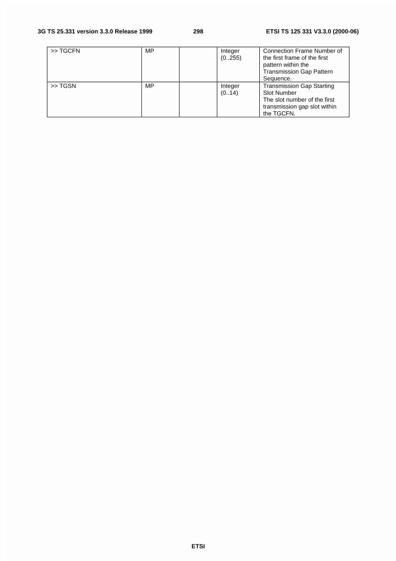
ETSI
ETSI TS 125 331 V3.3.0 (2000-06)2983G TS 25.331 version 3.3.0 Release 1999
>> TGCFN MP Integer(0..255)
Connection Frame Number ofthe first frame of the firstpattern within theTransmission Gap PatternSequence.
>> TGSN MP Integer(0..14)
Transmission Gap StartingSlot NumberThe slot number of the firsttransmission gap slot withinthe TGCFN.

ETSI
ETSI TS 125 331 V3.3.0 (2000-06)2993G TS 25.331 version 3.3.0 Release 1999
>>TGL1 MP Integer(1..14)
The length of the firstTransmission Gap within thetransmission gap patternexpressed in number of slots
>> TGL2 MD Integer(1..14)
The length of the secondTransmission Gap within thetransmission gap pattern. Ifomitted, then TGL2=TGL1.
>>TGD MP Integer(15..269,undefined)
Transmission gap distanceindicates the number of slotsbetween starting slots of twoconsecutive transmission gapswithin a transmission gappattern. If there is only onetransmission gap in thetransmission gap pattern, thisparameter shall be set to zero.
>> TGPL1 MP Integer(1..144)
The duration of transmissiongap pattern 1.
>> TGPL2 MD Integer(1..144)
The duration of transmissiongap pattern 2. If omitted, thenTGPL2=TGPL1.
>>RPP MP Enumerated(mode 0,mode 1).
Recovery Period Powercontrol mode during the frameafter the transmission gapwithin the compressed frame.Indicates whether normal PCmode or compressed PCmode is applied
>>ITP MP Enumerated(mode 0,mode 1).
Initial Transmit Power is theuplink power control method tobe used to compute the initialtransmit power after thecompressed mode gap.
>>UL/DL mode MP Enumerated(UL only, DLonly, UL/DL)
Defines whether only DL, onlyUL, or combined UL/DLcompressed mode is used.
>> Downlink compressed modemethod
CV DL Enumerated(puncturing,SF/2, higherlayerscheduling)
Method for generatingdownlink compressed modegap
>> Uplink compressed modemethod
CV UL Enumerated(SF/2, none,higher layerscheduling)
Method for generating uplinkcompressed mode gap
>>Downlink frame type MP Enumerated(A, B)
>>DeltaSIR1 MP Real(0..3 bystep of 0.1)
Delta in DL SIR target value tobe set in the UE during thecompressed framescorresponding to the firsttransmission gap in thetransmission gap pattern(without including the effect ofthe bit-rate increase)
>>DeltaSIRafter1 MP Real(0..3 bystep of 0.1)
Delta in DL SIR target value tobe set in the UE one frameafter the compressed framescorresponding to the firsttransmission gap in thetransmission gap pattern.

ETSI
ETSI TS 125 331 V3.3.0 (2000-06)3003G TS 25.331 version 3.3.0 Release 1999
>>DeltaSIR2 OP Real(0..3 bystep of 0.1)
Delta in DL SIR target value tobe set in the UE during thecompressed framescorresponding to the secondtransmission gap in thetransmission gap pattern(without including the effect ofthe bit-rate increase)When omitted, DeltaSIR2 =DeltaSIR1.
Range Bound ExplanationMaxTGPS Maximum number of transmission gap pattern
sequences. Value 6.
Condition ExplanationUL This information element is only sent when the value
of the "UL/DL mode" IE is "UL only" or "UL/DL".DL This information element is only sent when the value
of the "UL/DL mode" IE is "DL only" or "UL/DL".
10.3.6.28 DPCH Compressed Mode Status Info
Information Element/Groupname
Need Multi Type andreference
Semantics description
Transmission gap patternsequence
1 to<MaxTGPS>
> TGPSI MP Integer(1..<MaxTGPS>)
Transmission Gap PatternSequence Identifier
> TGPS Status Flag MP Enumerated(active,inactive)
This flag indicates the currentstatus of the TransmissionGap Pattern Sequence,whether it shall be active orinactive.
10.3.6.29 Dynamic persistence level
Information Element/Groupname
Need Multi Type andreference
Semantics description
Dynamic persistence level MP Integer(1..8) Level shall be mapped to adynamic persistence value inthe range 0 .. 1.

ETSI
ETSI TS 125 331 V3.3.0 (2000-06)3013G TS 25.331 version 3.3.0 Release 1999
10.3.6.30 Frequency info
Information Element/Groupname
Need Multi Type andreference
Semantics description
CHOICE mode MP>FDD>>UARFCN uplink (Nu) MP Integer(0..
16383)[25.101]
>>UARFCN downlink (Nd) OP Integer(0 ..16383)
[25.101]If IE not present, defaultduplex distance of 190 MHzshall be used.
>TDD>>UARFCN (Nt) MP Integer(0 ..
16383)[25.102]
10.3.6.31 Individual timeslot info
Information Element/Groupname
Need Multi Type andreference
Semantics description
Timeslot number MP Timeslotnumber10.3.6.72
Timeslot within a frame
TFCI existence CH Boolean TRUE indicates that the TFCIexists. It shall be coded in thefirst physical channel of thistimeslot.
Midamble Shift and burst type MP Midambleshift andbursttype10.3.6.35
10.3.6.32 Individual Timeslot interference
Parameters used by the UE for uplink open loop power control in TDD.
Information element Need Multi Type andreference
Semantics description
Timeslot number MP Timeslotnumber10.3.6.72
UL Timeslot Interference MP ULInterference 10.3.6.75
10.3.6.33 Maximum allowed UL TX power
This information element indicates the maximum allowed uplink transmit power.
Information Element Need Multi Type andreference
Semantics description
Maximum allowed UL TX power MP Integer(-50..33)
In dBmAt least 44 spare values areneededCriticality: reject is needed
10.3.6.34 Midamble configuration
NOTE: Only for TDD.

ETSI
ETSI TS 125 331 V3.3.0 (2000-06)3023G TS 25.331 version 3.3.0 Release 1999
Information Element/Groupname
Need Multi Type andreference
Semantics description
Midamble burst type 1 MD Integer(4,8,16)
Maximum number of midambleshifts for bursttype 1. Defaultvalue is 8.
Midamble burst type 2 MD Integer(3,6)
Maximum number of midambleshifts for bursttype 2. Defaultvalue is 3.
Default value is all the subfields set to their default value.
10.3.6.35 Midamble shift and burst type
NOTE: Only for TDD.
Information Element/Groupname
Need Multi Type andreference
Semantics description
CHOICE Burst Type MP>Type 1>>Midamble Shift MD Integer(0..15
)Default value is the midambleshift selected by layer 1.
>Type 2>>Midamble Shift MD Integer(0..5) Default value is the midamble
shift selected by layer 1.
10.3.6.36 PDSCH code mapping
NOTE: Only for FDD.
This IE indicates the association between each possible value of TFCI(field 2) and the corresponding PDSCHchannelisation code(s). There are three fundamentally different ways that the UTRAN must choose between in order tosignal the mapping information, these are described below. The signalling capacity consumed by the different methodswill vary depending on the way in which the UTRAN configures usage of the DSCH. A fourth option is also providedwhich allows the UTRAN to replace individual entries in the TFCI(field 2) to PDSCH code mapping table with newPDSCH code values.
There are four different signalling methods defined. The signalling method shall be selected by the UTRAN.
Method #1 - Using code range
The mapping is described in terms of a number of groups, each group associated with a given spreading factor. The UEmaps TFCI(field2) values to PDSCH codes in the following way. The PDSCH code used for TFCI(field 2) = 0, is givenby the SF and code number = 'PDSCH code start' of Group = 1. The PDSCH code used for TFCI( field 2) = 1, is givenby the SF and code number = 'PDSCH code start' + 1. This continues, with unit increments in the value of TFCI(field 2)mapping to unit increments in code number up until the point that code number = 'PDSCH code stop'. The processcontinues in the same way for the next group with the TFCI(field 2) value used by the UE when constructing itsmapping table starting at the largest value reached in the previous group plus one. In the event that 'PDSCH code start' ='PDSCH code stop' (as may occur when mapping the PDSCH root code to a TFCI (field 2) value) then this is to beinterpreted as defining the mapping between the channelisation code and a single TFCI (i.e., TFCI(field 2) should notbe incremented twice).
Note that each value of TFCI (field 2) is associated with a given 'code number' and when the 'multi-code info' parameteris greater than 1, then each value of TFCI (field 2) actually maps to a set of PDSCH codes. In this case contiguouscodes are assigned, starting at the channelisation code denoted by the 'code number' parameter and including all codeswith code numbers up to and including 'code number' - 1 + the value given in the parameter 'multi-code info'.
Method #2 - Using TFCI range
The mapping is described in terms of a number of groups, each group corresponding to a given PDSCH channelisationcode. The PDSCH code specified in the first group applies for all values of TFCI(field 2) between 0 and the specified'Max TFCI(field2)'. The PDSCH code specified in the second group applies for all values of TFCI(field 2) between the'Max TFCI(field2) value' specified in the last group plus one and the specified 'Max TFCI(field2)' in the second group.

ETSI
ETSI TS 125 331 V3.3.0 (2000-06)3033G TS 25.331 version 3.3.0 Release 1999
The process continues in the same way for the following groups with the TFCI(field 2) value starting at the largestvalue reached in the previous group plus one.
Method #3 - Explicit
The mapping between TFCI(field 2) value and PDSCH channelisation code is spelt out explicitly for each value ofTFCI (field2)
Information Element/Groupname
Need Multi Type andreference
Semantics description
DL Scrambling Code MD Secondaryscramblingcode10.3.6.64
Scrambling code on whichPDSCH is transmitted.Default is the same scramblingcode as for the Primary CPICH
Choice signalling method MP>code range>>PDSCH code mapping MP 1 to <
maxPDSCH-TFCIgroups >
>>>Spreading factor MP Integer(4, 8,16, 32, 64,128, 256)
At least 1 spare value neededCriticality: reject is needed
>>>multi-code info MP Integer(1..16)
This parameter indicates thenumber of PDSCH transmittedto the UE. The PDSCH codesall have the same SF asdenoted by the 'Spreadingfactor' parameter. Contiguouscodes are assigned, starting atthe channelisation codedenoted by the spreadingfactor and code numberparameter and including allcodes, with code numbers upto and including 'code number'- 1 + 'multi-code info'. Notethat 'code number'-1+'multi-code info' will not be allowed toexceed 'Spreading factor - 1'
>>Code number (for PDSCHcode start)
MP Integer(0..Spreadingfactor-1)
>>Code number (for PDSCHcode stop)
MP Integer(0..Spreadingfactor-1)
>TFCI range>>DSCH mapping MP 1 to <
maxPDSCH-TFCIgroups >
>>>Max TFCI(field2) value MP Integer(1..1023)
This is the maximum value inthe range of TFCI(field 2)values for which the specifiedPDSCH code applies
>>>Spreading factor (forPDSCH code)
MP Integer(4, 8,16, 32, 64,128, 256)
At least 1 spare value neededCriticality: reject is needed
>>>Code number (for PDSCHcode)
MP Integer(0..Spreadingfactor-1)
>>>multi-code info MP Integer(1..16)
Semantics as described forthis parameter above
>Explicit

ETSI
ETSI TS 125 331 V3.3.0 (2000-06)3043G TS 25.331 version 3.3.0 Release 1999
>>PDSCH code info MP 1 to <maxTFCI-2-Combs >
The first instance of theparameter PDSCH codecorresponds to TFCI (field2) =0, the second to TFCI(field 2)= 1and so on.
>>>Spreading factor (forPDSCH code)
MP Integer(4, 8,16, 32, 64,128, 256)
At least 1 spare value neededCriticality: reject is needed
>>>Code number (for PDSCHcode)
MP Integer(0..Spreadingfactor-1)
>>>multi-code info MP Integer(1..16)
Semantics as described forthis parameter above
>Replace This choice is made if thePDSCH code(s) associatedwith a given value of TFCI(field2) is to be replaced.
>>Replaced PDSCH code MP 1 to <maxTFCI-2-Combs >
Identity of the PDSCH code(s)to be used for the specifiedvalue of TFCI(field 2). Thesecode identity(s) replace anythat had been specified before
>>>TFCI (field 2) MP Integer(0..1023)
Value of TFCI(field 2) forwhich PDSCH code mappingwill be changed
>>>Spreading factor (forPDSCH code)
MP Integer(4, 8,16, 32, 64,128, 256)
>>>Code number (for PDSCHcode)
MP Integer(0..Spreadingfactor-1)
>>>multi-code info MP Integer(1..16)
Semantics as described forthis parameter above
10.3.6.37 PDSCH info
NOTE: Only for TDD.
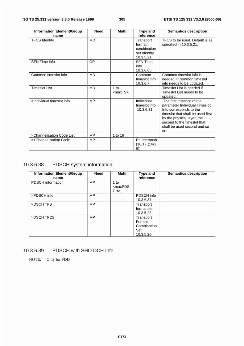
ETSI
ETSI TS 125 331 V3.3.0 (2000-06)3053G TS 25.331 version 3.3.0 Release 1999
Information Element/Groupname
Need Multi Type andreference
Semantics description
TFCS Identity MD Transportformatcombinationset Identity10.3.5.21
TFCS to be used. Default is asspecified in 10.3.5.21.
SFN Time info OP SFN Timeinfo10.3.6.65
Common timeslot info MD Commontimeslot info10.3.6.7
Common timeslot info isneeded if Common timeslotinfo needs to be updated.
Timeslot List MD 1 to<maxTS>
Timeslot List is needed ifTimeslot List needs to beupdated.
>Individual timeslot info MP Individualtimeslot info 10.3.6.31
The first instance of theparameter Individual TimeslotInfo corresponds to thetimeslot that shall be used firstby the physical layer, thesecond to the timeslot thatshall be used second and soon.
>Channelisation Code List MP 1 to 16>>Channelisation Code MP Enumerated(
(16/1)..(16/16))
10.3.6.38 PDSCH system information
Information Element/Groupname
Need Multi Type andreference
Semantics description
PDSCH information MP 1 to<maxPDSCH>
>PDSCH info MP PDSCH info10.3.6.37
>DSCH TFS MP Transportformat set10.3.5.23
>DSCH TFCS MP TransportFormatCombinationSet10.3.5.20
10.3.6.39 PDSCH with SHO DCH Info
NOTE: Only for FDD

ETSI
ETSI TS 125 331 V3.3.0 (2000-06)3063G TS 25.331 version 3.3.0 Release 1999
Information Element/Groupname
Need Multi Type andreference
Semantics description
DSCH radio link identifier MP Integer(0..511)
This parameter indicates onwhich radio link the user willbe allocated resource on theDSCH. The CPICH scramblingcode will be used for thispurpose.
TFCI Combining set OP This is used to indicate whichof the downlink TFCI(field 2)transmissions made on theDPCCHs within the active setshould be soft combined onthe physical layer. Thisparameter may only be sent ifthere is a 'hard' split of theTFCI field and in this case thesending of the parameter isoptional.
Radio link identifier OP 1 to<maxRL>
>Primary CPICH info MP PrimaryCPICH info10.3.6.51
The CPICH scrambling code isused for this purpose
10.3.6.40 Persistence scaling factors
This IE defines scaling factors associated with ASC 2 – ASC 7 (multiplicity corresponds to the number of PRACHpartitions minus 2) to be applied to the dynamic persistence value. This IE shall not be present in system information ifonly ASC 0 and ASC 1 are defined. If it is not present for ASC >1, default persistence scaling factor 1 shall be used(see Sec. 8.5.14).
Information Element/Groupname
Need Multi Type andreference
Semantics description
Access Service Class 1 tomaxASCpersist
> Persistence scaling factor MP Real(0.9..0.2, by step of0.1)
Scaling factors in the range0,…,1

ETSI
ETSI TS 125 331 V3.3.0 (2000-06)3073G TS 25.331 version 3.3.0 Release 1999
10.3.6.41 PICH Info
Information Element/Groupname
Need Multi Type andreference
Semantics description
CHOICE mode MP>FDD>>Secondary scrambling code MD Secondary
scramblingcode10.3.6.64
Default is the same scramblingcode as for the Primary CPICH
>>Channelisation code MP Integer(0..255)
SF is fixed and equal to 256
>>Number of PI per frame MP Integer (18,36 72 144)
>>STTD indicator MP STTDIndicator10.3.6.68
>TDD>>Channelisation code MD Enumerated
((16/1)...(16/16))
Default value is thechannelisation code used bythe SCCPCH carrying theassociated PCH.
>>Timeslot MD Timeslotnumber10.3.6.72
Default value is the timeslotused by the SCCPCH carryingthe associated PCH.
>>Burst type MP Enumerated(Typ1,Typ2)
>>Midamble shift MD Midambleshift10.3.6.35
Default value is the midambleshift used by the SCCPCHcarrying the associated PCH.
>>Repetition period/length MD Enumerated((4/2),(8/2),(8/4),(16/2),(16/4),(32/2),(32/4),(64/2),(64/4))
Default value is "(64/2)".
>>Offset MP Integer(0...Repetition period -1)
SFN mod Repetitionperiod =Offset.
>>Paging indicator length MD Integer (2, 4,8)
Indicates the length of onepaging indicator in symbols..Default value is 2.
>>NGAP MD Integer(2, 4,8)
Number of frames between thelast frame carrying PICH forthis Paging Occasion and thefirst frame carrying pagingmessages for this PagingOccasion. Default value is 4.
>>NPCH MD Integer(1 ..8)
Number of paging groups.Default value is 2.
10.3.6.42 PICH Power offset
NOTE: Only for FDD.
This is the power transmitted on the PICH minus power of the Primary CPICH.
Information Element/Groupname
Need Multi Type andreference
Semantics description
PICH Power offset MP Integer(-10 ..+5)
Offset in dB

ETSI
ETSI TS 125 331 V3.3.0 (2000-06)3083G TS 25.331 version 3.3.0 Release 1999
10.3.6.43 PRACH Channelisation Code
NOTE: Only for TDD.
Information Element/Groupname
Need Multi Type andreference
Semantics description
CHOICE SF MP>SF16>>Channelisation Code List MP 1 to 8>>>Channelisation code MP Enumerated
((16/1)...(16/16))
1:1 mapping betweenspreading code and midambleshift
>SF8>>Channelisation Code List MP 1 to 8>>>Channelisation Code MP Enumerated(
(8/1)..(8/8))
10.3.6.44 PRACH info (for RACH)
Information Element/Groupname
Need Multi Type andreference
Semantics description
CHOICE mode MP>FDD>>Available Signature MP 1 to
<maxSig>>>>Signature MP Integer
(0..15)>>Available SF MP Integer
(32,64,128,256)
In chips per symbolDefines the smallest permittedSF (i.e. the maximum rate)
>>Scrambling code number MP Integer (0 ..15)
Identification of scramblingcode see TS 25.213
>>Puncturing Limit MP Real(0.40..1.00 by step of0.04)
>>Available Sub Channelnumber
MP 1 to <maxSubCh>
>>>Sub Channel number MP Integer(0..11)
>TDD>>Timeslot MP Timeslot
number10.3.6.72
>>PRACH Channelisation Code MP PRACHChannelisation Code10.3.6.43
>>PRACH Midamble OP Enumerated(Direct,Direct/Inverted)
Direct or direct and invertedmidamble are used for PRACH
Multi Bound ExplanationMaxSubCh Maximum number of available sub channels = 12MaxSig Maximum number of available signatures = 16
10.3.6.45 PRACH partitioning

ETSI
ETSI TS 125 331 V3.3.0 (2000-06)3093G TS 25.331 version 3.3.0 Release 1999
Information Element/Groupname
Need Multi Type andreference
Semantics description
CHOICE mode>FDD>>Access Service class MP 1 to
maxASC>>>Available signature StartIndex
MP Integer(0..15)
>>>Available signature EndIndex
MP Integer(0..15)
>>>Available sub-channel StartIndex
MP Integer(0..11)
>>>Available sub-channel EndIndex
MP Integer(0..11)
>>TDD>>>Access Service class List MP 1 to
maxASCList of Access Service classes
>>>>Access service class Index MP Integer(1..8)>>>>Repetition Period MD Integer(1, 2,
4, 8)Default value is continuous.Value 1 indicates continuousallocation
>>>>Offset MP Integer(0..RepetitionPeriod - 1)
Note that this is empty ifrepetition period is set to 1
The following description applies to FDD only.
The list of available signatures is renumbered from signature index 0 to signature index N-1, where N is the number ofavailable signatures, starting with the lowest available signature number and continuing in sequence, in the order ofincreasing signature numbers.
- List of available signatures : 16 or less signatures are available.
- Ex : only signatures 0, 5, 10 and 15 are available, then :
- Signature 0 is : available signature index 0
- Signature 5 is : available signature index 1
- Signature 10 is : available signature index 2
- Signature 15 is : available signature index 3
The list of available access-slot sub-channels is renumbered from access-slot sub-channel index 0 to access-slot sub-channel index M-1, where M is the number of available access-slot sub-channels, starting with the lowest availableaccess-slot sub-channel number and continuing in sequence, in the order of increasing access-slot sub-channel numbers.
- List of available Access Slot channels : 12 or less sub-channels are available.
- Ex : only sub-channels 0,1; 4,5; 8,9 are present, then :
- Sub-channel 0 is : available sub-channel index 0
- Sub-channel 1 is : available sub-channel index 1
- Sub-channel 4 is : available sub-channel index 2
- Sub-channel 5 is : available sub-channel index 3
- Sub-channel 8 is : available sub-channel index 4
- Sub-channel 9 is : available sub-channel index 5
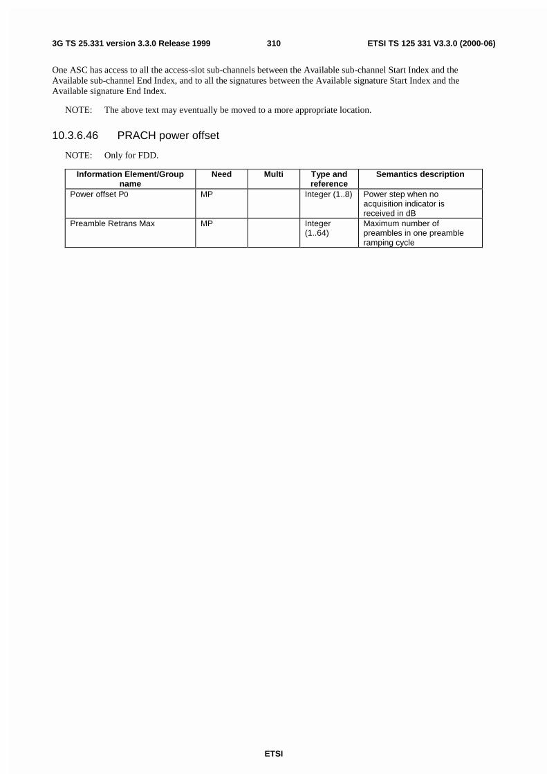
ETSI
ETSI TS 125 331 V3.3.0 (2000-06)3103G TS 25.331 version 3.3.0 Release 1999
One ASC has access to all the access-slot sub-channels between the Available sub-channel Start Index and theAvailable sub-channel End Index, and to all the signatures between the Available signature Start Index and theAvailable signature End Index.
NOTE: The above text may eventually be moved to a more appropriate location.
10.3.6.46 PRACH power offset
NOTE: Only for FDD.
Information Element/Groupname
Need Multi Type andreference
Semantics description
Power offset P0 MP Integer (1..8) Power step when noacquisition indicator isreceived in dB
Preamble Retrans Max MP Integer(1..64)
Maximum number ofpreambles in one preambleramping cycle
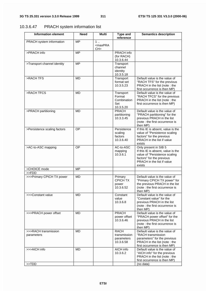
ETSI
ETSI TS 125 331 V3.3.0 (2000-06)3113G TS 25.331 version 3.3.0 Release 1999
10.3.6.47 PRACH system information list
Information element Need Multi Type andreference
Semantics description
PRACH system information MP 1 ..<maxPRACH>
>PRACH info MP PRACH info(for RACH)10.3.6.44
>Transport channel identity MP Transportchannelidentity10.3.5.18
>RACH TFS MD Transportformat set10.3.5.23
Default value is the value of"RACH TFS" for the previousPRACH in the list (note : thefirst occurrence is then MP)
>RACH TFCS MD TransportFormatCombinationSet10.3.5.20
Default value is the value of"RACH TFCS" for the previousPRACH in the list (note : thefirst occurrence is then MP)
>PRACH partitioning MD PRACHpartitioning10.3.3.45
Default value is the value of"PRACH partitioning" for theprevious PRACH in the list(note : the first occurrence isthen MP)
>Persistence scaling factors OP Persistencescalingfactors10.3.6.40
If this IE is absent, value is thevalue of "Persistence scalingfactors" for the previousPRACH in the list if valueexists
>AC-to-ASC mapping OP AC-to-ASCmapping10.3.6.1
Only present in SIB 5If this IE is absent, value is thevalue of "Persistence scalingfactors" for the previousPRACH in the list if valueexists
>CHOICE mode MP>>FDD>>>Primary CPICH TX power MD Primary
CPICH TXpower10.3.6.52
Default value is the value of"Primary CPICH TX power" forthe previous PRACH in the list(note : the first occurrence isthen MP)
>>>Constant value MD Constantvalue10.3.6.8
Default value is the value of"Constant value" for theprevious PRACH in the list(note : the first occurrence isthen MP)
>>>PRACH power offset MD PRACHpower offset10.3.6.46
Default value is the value of"PRACH power offset" for theprevious PRACH in the list(note : the first occurrence isthen MP)
>>>RACH transmissionparameters
MD RACHtransmissionparameters10.3.6.58
Default value is the value of"RACH transmissionparameters" for the previousPRACH in the list (note : thefirst occurrence is then MP)
>>>AICH info MD AICH info10.3.6.2
Default value is the value of"AICH info" for the previousPRACH in the list (note : thefirst occurrence is then MP)
>>TDD (no data)

ETSI
ETSI TS 125 331 V3.3.0 (2000-06)3123G TS 25.331 version 3.3.0 Release 1999
10.3.6.48 Predefined PhyCH configuration
This information element concerns a pre- defined configuration of physical channel parameters.
Information Element/Groupname
Need Multi Type andReference
Semantics description
Uplink radio resourcesUplink DPCH info MP Uplink
DPCH infoPre10.3.6.78
Downlink radio resourcesCHOICE mode>FDD>>Downlink informationcommon for all radio links
Downlinkinformationcommon forall radio linksPre10.3.6.22
>TDD (no data)
10.3.6.49 Primary CCPCH info
Information Element/Groupname
Need Multi Type andreference
Semantics description
CHOICE mode MP>FDD>>TX Diversity indicator MD Boolean Default value is "TRUE">TDD>>CHOICE SyncCase OP>>>Sync Case 1>>>>Timeslot MP Integer
(0...14)PCCPCH timeslot
>>>Sync Case 2>>>>Timeslot MP Integer(0..6)>>Cell parameters ID OP Integer
(0...127)The Cell parameters ID isdescribed in 25.223.
>>Block STTD indicator MD Block STTDindicator10.3.6.5
Default value is "TRUE"
10.3.6.50 Primary CCPCH TX Power
NOTE: Only for TDD.
Information Element/groupname
Need Multi Type andreference
Semantics description
Primary CCPCH Tx Power MP Integer(6..43)
In dBm
10.3.6.51 Primary CPICH info
NOTE: Only for FDD.
Information Element/Groupname
Need Multi Type andreference
Semantics description
Primary scrambling code MP Integer(0..511)

ETSI
ETSI TS 125 331 V3.3.0 (2000-06)3133G TS 25.331 version 3.3.0 Release 1999
10.3.6.52 Primary CPICH Tx power
NOTE: Only for FDD.
Information Element/Groupname
Need Multi Type andreference
Semantics description
Primary CPICH Tx Power MP Integer(-10..50)
At least 3 spare values areneeded for future extensionswith criticality reject
10.3.6.53 Primary CPICH usage for channel estimation
NOTE: Only for FDD.
Information Element/Groupname
Need Multi Type andReference
Semantics description
Primary CPICH usage forchannel estimation
MP Enumerated(PrimaryCPICH maybe used,PrimaryCPICH shallnot be used)
10.3.6.54 PUSCH info
NOTE: Only for TDD.
Information Element/Groupname
Need Multi Type andreference
Semantics description
TFCS Identity MD Transportformatcombinationset Identity10.3.5.21
Default is as specified in10.3.5.21.
SFN Time info OP SFN Timeinfo10.3.6.65
Common timeslot info MD Commontimeslot info10.3.6.7
Default is the old Commontimeslot info.
Timeslot List MD 1 to<maxTS>
Default is the old Timeslot List.
>Individual timeslot info MP Individualtimeslot info10.3.6.31
The first instance of theparameter Individual TimeslotInfo corresponds to thetimeslot that shall be used firstby the physical layer, thesecond to the timeslot thatshall be used second and soon.
>Channelisation Code List MP 1..2>>Channelisation Code MP Enumerated(
(1/1),)(2/1),(2/2),(4/1)..(4/4),(8/1)..(8/8),(16/1)..(16/16))
10.3.6.55 PUSCH Capacity Allocation info
NOTE: Only for TDD.

ETSI
ETSI TS 125 331 V3.3.0 (2000-06)3143G TS 25.331 version 3.3.0 Release 1999
Information Element/Groupname
Need Multi Type andreference
Semantics description
CHOICE PUSCH allocation MP>PUSCH allocation pending (no data)>PUSCH allocation assignment>>PUSCH power control info OP PUSCH
powercontrol info10.3.6.56
>>PUSCH info MP PUSCH info10.3.6.54
10.3.6.56 PUSCH power control info
NOTE: Only for TDD.
Interference level measured for a frequency at the UTRAN access point used by UE to set PUSCH output power.
Information Element/Groupname
Need Multi Type andreference
Semantics description
UL target SIR MP Real (-11 ..20 by step of0.5)
in dB
10.3.6.57 PUSCH system information
Information Element/Groupname
Need Multi Type andreference
Semantics description
PUSCH information MP 1 to<maxPUSCH>
>PUSCH info MP PUSCH info10.3.6.54
>USCH TFS MP Transportformat set10.3.5.23
>USCH TFCS MP TransportFormatCombinationSet10.3.5.20
10.3.6.58 RACH transmission parameters
NOTE: Only for FDD.
Information Element/Groupname
Need Multi Type andreference
Semantics description
Mmax MP Integer(1..32)
Maximum number of preamblecycles
NB01min MP Integer(0..50)
Sets lower bound for randomback-off
NB01max MP Integer(0..50)
Sets upper bound for randomback-off

ETSI
ETSI TS 125 331 V3.3.0 (2000-06)3153G TS 25.331 version 3.3.0 Release 1999
10.3.6.59 Radio link addition information
Information Element/Groupname
Need Multi Type andreference
Semantics description
Primary CPICH info MP PrimaryCPICH info10.3.6.51
Downlink DPCH info for each RL MP DownlinkDPCH infofor each RL10.3.6.17
TFCI combining indicator OP TFCIcombiningindicator10.3.6.70
Secondary CCPCH info OP SecondaryCCPCH info10.3.6.61
Note 1
TFCS OP Transportformat set10.3.5.23
For FACHs and PCHNote 1
FACH/PCH information OP 1 to<maxFACHcount>
Note 1
>TFS OP Transportformat set10.3.5.23
For each FACHs and PCHNote 1
References to systeminformation blocks
OP 1 to<maxSIB-FACH>
Note 1
>Scheduling information MP Schedulinginformation10.3.8.12
Note 1
NOTE 1: These IEs are present when the UE needs to listen to system information on FACH in CELL_DCH state.
10.3.6.60 Radio link removal information
Information Element/Groupname
Need Multi Type andreference
Semantics description
Primary CPICH info MP PrimaryCPICH info10.3.6.51

ETSI
ETSI TS 125 331 V3.3.0 (2000-06)3163G TS 25.331 version 3.3.0 Release 1999
10.3.6.61 Secondary CCPCH info
Information Element/Groupname
Need Multi Type andreference
Semantics description
Selection Indicator CV-BCH Enumerated(On, Off)
Needed if send on BCH.
CHOICE mode MP>FDD>>Primary CPICH usage forchannel estimation
MP PrimaryCPICHusage forchannelestimation10.3.6.53
>>Secondary CPICH info OP SecondaryCPICH info10.3.6.63
>>Secondary scrambling code MD Secondaryscramblingcode10.3.6.64
Default is the same scramblingcode as for the Primary CPICH
>>STTD indicator MD STTDIndicator10.3.6.68
Default value is "TRUE"
>>Spreading factor MP Integer(4, 8,16, 32, 64,128, 256)
>>Code number MP Integer(0..Spreadingfactor - 1)
>>Pilot symbol existence MD Boolean TRUE means the existence.Default value is "TRUE"
>>TFCI existence MD Boolean TRUE means the existence.Default value is "TRUE"
>>Fixed or Flexible Position MD Enumerated(Fixed,Flexible)
Default value is "Flexible"
>>Timing Offset MD Integer(0..38144 by stepof 256)
ChipDelay of the SecondaryCCPCH relative to the PrimaryCCPCH.Default value is 0.
>TDD>>Offset MD Integer
(0...Repetition Period -1)
SFN modulo Repetition period= offset. Repetition period isthe one indicated in theaccompanying Commontimeslot info IE
>>Common timeslot info MP Commontimeslot info10.3.6.7
>>Individual timeslot info MP Individualtimeslot info10.3.6.31
>>Code List MP 1..<maxCodesCount>
>>>Channelisation Code MP Enumerated((16/1)..(16/16))

ETSI
ETSI TS 125 331 V3.3.0 (2000-06)3173G TS 25.331 version 3.3.0 Release 1999
10.3.6.62 Secondary CCPCH system information
Information element Need Multi Type andreference
Semantics description
Secondary CCPCH systeminformation
MP 1 to<maxSCCPCH>
>Secondary CCPCH info MP SecondaryCCPCH info10.3.6.61
Note 1
>TFCS MD Transportformat set10.3.5.23
For FACHs and PCHDefault value is the value of"TFCS" for the previousSCCPCH in the list (note : thefirst occurrence is then MP)
>FACH/PCH information MD 1 to<maxFACHPCH>
Default value is the value of"FACH/PCH" for the previousSCCPCH in the list (note : thefirst occurrence is then MP)
>>Transport channel identity MP Transportchannelidentity10.3.5.18
>>TFS MP Transportformat set10.3.5.23
For each FACHs and PCHNote 2
>>CTCH indicator MP Boolean The value "TRUE" indicatesthat a CTCH is mapped on theFACH, and "FALSE" that noCTCH is mapped.
>PICH info OP PICH info10.3.6.41
PICH info is present only whenPCH is multiplexed onSecondary CCPCH
NOTE 1: The secondary CCPCH carrying the PCH shall be the first Secondary CCPCH information in the list.
NOTE 2: TFS for PCH shall be the first FACH/PCH information in the list if PCH exists.
10.3.6.63 Secondary CPICH info
NOTE: Only for FDD.
Information Element/Groupname
Need Multi Type andreference
Semantics description
Secondary scrambling code MD Secondaryscramblingcode10.3.6.64
Default is the same scramblingcode as for the Primary CPICH
Channelisation code MP Integer(0..255)
SF=256
10.3.6.64 Secondary scrambling code
Information Element/Groupname
Need Multi Type andreference
Semantics description
Secondary scrambling code MP Integer(1..15)
At least 1 spare value neededCriticality: reject is needed

ETSI
ETSI TS 125 331 V3.3.0 (2000-06)3183G TS 25.331 version 3.3.0 Release 1999
10.3.6.65 SFN Time info
Information Element/Groupname
Need Multi Type andreference
Semantics description
Activation time MD Integer(0..4094)
System frame number start ofthe physical channelexistence. Default value is"Now"
Duration MD Integer(1..4096)
Total number of frames thephysical channel will exist.Default value is "infinite".
10.3.6.66 SSDT cell identity
NOTE: Only for FDD.
This IE is used to associate a cell identity with a given radio link.
Information Element/Groupname
Need Multi Type andreference
Semantics description
SSDT cell id MP Enumerated(a, b, c, d, e,f, g, h)
10.3.6.67 SSDT information
NOTE: Only for FDD.
This information element indicates the status (e.g. initiated/terminated) of the Site Selection.
Diversity Transmit power control (SSDT). It is used to change the SSDT status. The parameter 'code word set' indicateshow cell identities are coded (using many bits or few, values are long, medium, or short).
Information Element/Groupname
Need Multi Type andreference
Semantics description
S field MP Integer (1, 2) in bitsCode Word Set MP Enumerated
(long,medium,short, SSDToff)
NOTE: These parameters shall be set optionally associated with DL DPCH info but not for each RL.
10.3.6.68 STTD indicator
Indicates whether STTD is used or not.
Information Element/Groupname
Need Multi Type andreference
Semantics description
STTD Indicator MP Boolean TRUE means that STTD isused

ETSI
ETSI TS 125 331 V3.3.0 (2000-06)3193G TS 25.331 version 3.3.0 Release 1999
10.3.6.69 TFC Control duration
Information Element/Groupname
Need Multi Type andreference
Semantics description
TFC Control duration MP Integer (1,16, 24, 32,48, 64, 128,192, 256,512)
Defines the period in multiplesof 10 ms frames for which thedefined TFC sub-set is to beapplied.At least 8 spare values forfuture extensions withcriticality reject are needed.
10.3.6.70 TFCI Combining Indicator
NOTE: Only for FDD.
This IE indicates whether the TFCI (field 2) which will be transmitted on the DPCCH of a newly added radio linkshould be soft combined with the others in the TFCI (field 2) combining set. This IE can only be sent when the UE is inCELL_DCH state with a DSCH transport channel assigned and when there is a 'hard' split in the TFCI field (such thatTFCI1 and TFCI2 have their own separate block coding).
Information Element/Groupname
Need Multi Type andreference
Semantics description
TFCI combining indicator MP Boolean TRUE means that TFCI iscombined
10.3.6.71 Time info
Information Element/Groupname
Need Multi Type andreference
Semantics description
Activation time MD Activationtime 10.3.3.1
Frame number start of thephysical channel existence.Default value is "Now"
Duration MD Integer(1..4096)
Total number of frames thephysical channel will exist.Default value is "infinite".
10.3.6.72 Timeslot number
Information Element/Groupname
Need Multi Type andreference
Semantics description
Timeslot number MP Integer(0..14)
Timeslot within a frame
10.3.6.73 TPC combination index
NOTE: Only for FDD.
Information Element/Groupname
Need Multi Type andreference
Semantics description
TPC combination index MP Integer(0..5)
Radio links with the sameindex have TPC bits, which forthe UE are known to be thesame.
10.3.6.74 TX Diversity Mode
NOTE: Only for FDD.

ETSI
ETSI TS 125 331 V3.3.0 (2000-06)3203G TS 25.331 version 3.3.0 Release 1999
Information Element/Groupname
Need Multi Type andreference
Semantics description
Tx diversity Mode MP Enumerated(none,STTD,closed loopmode1,closed loopmode2)
10.3.6.75 UL interference
Information Element/Groupname
Need Multi Type andreference
Semantics description
UL interference MP Integer (-110..-70)
In dBmAt least 23 spare values withcriticality reject are needed
NOTE: In TDD, this IE is a timeslot specific value.

ETSI
ETSI TS 125 331 V3.3.0 (2000-06)3213G TS 25.331 version 3.3.0 Release 1999
10.3.6.76 Uplink DPCH info
Information Element/Groupname
Need Multi Type andreference
Semantics description
Uplink DPCH power control info OP UplinkDPCH powercontrol info10.3.6.79
CHOICE mode MP>FDD>>Scrambling code type MP Enumerated(
short, long)>>Scrambling code number MP Integer(0..16
777215)>>Number of DPDCH MD Integer(2..m
axDPDCH)Default value is 1.Number of DPDCH is 1 inHANDOVER TO UTRANCOMMAND
>>Spreading factor MP Integer(4, 8,16, 32, 64,128, 256)
SF of the channelisation codefor data part
>>TFCI existence MD Boolean TRUE means existence.Default value is "TRUE"
>>Number of FBI bits CH Integer (1, 2) In bits. Number of FBI bits isneeded if SSDT or FB ModeTransmit Signalling issupported.
>>Puncturing Limit MP Real(0.40 ..1by step of0.04)
>TDD>>Uplink Timing Advance OP Uplink
TimingAdvance10.3.6.82
>>UL CCTrCH List MP 1 to<maxCCTrCH>
>>>TFCS Identity MD TransportFormatCombinationSet Identity10.3.5.21
Default value is 1.
>>>Time info MP Time info10.3.6.71
>>>Common timeslot info MD Commontimeslot info10.3.6.7
Default is the current Commontimeslot info
>>>Timeslot List MD 1 to<maxTS>
Default is the current TimeslotList
>>>>Individual timeslot info MP Individualtimeslot info10.3.6.31
The first instance of theparameter Individual TimeslotInfo corresponds to thetimeslot that shall be used firstby the physical layer, thesecond to the timeslot thatshall be used second and soon.
>>>>Code List MP 1..2>>>>>Channelisation Code MP Enumerated(
(1/1),)(2/1),(2/2),(4/1)..(4/4),(8/1)..(8/8),(16/1)..(16/16))

ETSI
ETSI TS 125 331 V3.3.0 (2000-06)3223G TS 25.331 version 3.3.0 Release 1999
Condition ExplanationSingle This IE is included if IE "Number of DPDCH" is "1"
10.3.6.77 Uplink DPCH info Post
Information Element/Groupname
Need Multi Type andreference
Semantics description
Uplink DPCH power control info MP UplinkDPCH powercontrol infoPost10.3.6.80
CHOICE mode MP>FDD>>Scrambling code type MP Enumerated(
short, long)>>Reduced scrambling codenumber
MP Integer(0..8191)
Sub-range of values for initialuse upon handover to UTRAN.
>>Spreading factor MP Integer(4, 8,16, 32, 64,128, 256)
SF of the channelisation codefor data partThere is only one DPDCH forthis case
>TDD (no data)>>Uplink Timing Advance OP Uplink
TimingAdvance10.3.6.82
>>Time info MP Time Info10.3.6.71
>>Common timeslot info MP CommonTimeslot Info10.3.6.7
>>Timeslot List MP 1 to <MaxTS>
>>>Individual timeslot info MP Individualtimeslot info10.3.6.31
The first instance of theparameter Individual TimeslotInfo corresponds to thetimeslot that shall be used firstby the physical layer, thesecond to the timeslot thatshall be used second and soon.
>>>Code List MP 1..2>>>>Channelisation Code MP Enumerated(
(1/1),)(2/1),(2/2),(4/1)..(4/4),(8/1)..(8/8),(16/1)..(16/16))

ETSI
ETSI TS 125 331 V3.3.0 (2000-06)3233G TS 25.331 version 3.3.0 Release 1999
10.3.6.78 Uplink DPCH info Pre
Information Element/Groupname
Need Multi Type andreference
Semantics description
Uplink DPCH power control info OP UplinkDPCH powercontrol infoPre10.3.6.81
CHOICE mode MP>FDD>>TFCI existence MP Boolean TRUE means existence.
Default value is "TRUE">>Puncturing Limit MP Real(0.40 ..1
by step of0.04)
>TDD (no data)
Condition ExplanationSingle This IE is included if IE "Number of DPDCH" is "1"
10.3.6.79 Uplink DPCH power control info
Parameters used by UE to set DPCH initial output power and to use for closed-loop power control in FDD andparameters for uplink open loop power control in TDD.
Information Element/Groupname
Need Multi Type andreference
Semantics description
CHOICE mode MP>FDD>>DPCCH Power offset MP Integer(-
164,..-6 bystep of 2)
In dB
>>PC Preamble MP Integer (0,15)
>>Power Control Algorithm MP Enumerated(algorithm 1,algorithm 2)
Specifies algorithm to be usedby UE to interpret TPCcommands
>>TPC step size CV algo Integer (1, 2) In dB>TDD>>UL target SIR MP Real (-11 ..
20 by step of0.5dB)
In dB
>>Individual timeslotinterference info
OP 1 to<maxTS>
>>> Individual timeslotinterference
MP Individualtimeslotinterference10.3.6.32
>>DPCH Constant Value OP ConstantValue10.3.6.8
Quality Margin
Condition Explanationalgo The IE is mandatory if "Power Control Algorithm" is
set to "algorithm 1", otherwise the IE is not needed
10.3.6.80 Uplink DPCH power control info Post
Parameters used by UE to set DPCH initial output power and to use for closed-loop power control.

ETSI
ETSI TS 125 331 V3.3.0 (2000-06)3243G TS 25.331 version 3.3.0 Release 1999
Information Element/Groupname
Need Multi Type andreference
Semantics description
CHOICE mode MP>FDD (no data)>>Power Control Algorithm MP Enumerated
(algorithm 1,algorithm 2)
Specifies algorithm to be usedby UE to interpret TPCcommands
>>TPC step size CV algo Integer (1, 2) In dB>TDD (no data)>>UL target SIR MP Real (-11 ..
20 by step of0.5dB)
In dB
>>UL Timeslot Interference MP ULInterference10.3.6.75
Condition Explanationalgo The IE is mandatory if "Power Control Algorithm" is
set to "algorithm 1", otherwise the IE is not needed
10.3.6.81 Uplink DPCH power control info Pre
Parameters used by UE to set DPCH initial output power and to use for closed-loop power control in FDD andparameters for uplink open loop power control in TDD.
Information Element/Groupname
Need Multi Type andreference
Semantics description
CHOICE mode MP>FDD>>DPCCH Power offset MP Integer(-
164..-6 bystep of 2)
In dB
>>PC Preamble MP Integer (0,15)
>TDD (No data)>>DPCH Constant Value MP Constant
Value10.3.6.8
Quality Margin
Condition ExplanationAlgo The IE is mandatory if "Power Control Algorithm" is
set to "algorithm 1", otherwise the IE is not needed
10.3.6.82 Uplink Timing Advance
NOTE: Only for TDD.
Information Element/Groupname
Need Multi Type andreference
Semantics description
UL Timing Advance MP Integer(0..63)
Absolute timing advance valueto be used to avoid large delayspread at the NodeB

ETSI
ETSI TS 125 331 V3.3.0 (2000-06)3253G TS 25.331 version 3.3.0 Release 1999
10.3.7 Measurement Information elements
10.3.7.1 Additional measurements list
Information Element/Groupname
Need Multi Type andreference
Semanticsdescription
Additional measurements MP 1 to<MaxAdditionalMeas>
>Additional measurementidentity
MP Measurementidentity number10.3.73
10.3.7.2 Cell info
Includes non-frequency related cell info used in the IE "inter-frequency cell info list" and "intra frequency cell info list".

ETSI
ETSI TS 125 331 V3.3.0 (2000-06)3263G TS 25.331 version 3.3.0 Release 1999
Information Element/Groupname
Need Multi Type andreference
Semantics description
Cell individual offset MD Real(-10..10by step of0.5)
In dBDefault value is 0 dBUsed to offset measuredquantity value
Reference time difference to cell OP Referencetimedifference tocell10.3.7.85
In chips.This IE is absent for servingcell.
CHOICE mode MP>FDD>>Primary CPICH info OP Primary
CPICH info10.3.6.51
This IE is absent only ifmeasuring RSSI only(broadband measurement.)
>>Primary CPICH Tx power OP PrimaryCPICH Txpower10.3.6.52
Required if calculatingpathloss.
>>Read SFN indicator MP Boolean TRUE indicates that read ofSFN is requested for the targetcell
>>TX Diversity Indicator MP Boolean>TDD>>Primary CCPCH info MP Primary
CCPCH info10.3.6.49
>>Primary CCPCH TX power OP PrimaryCCPCH TXpower10.3.6.50
>> Timeslot list OP 1 to<maxTS>
The UE shall report TimeslotISCP values according theorder of the listed Timeslotnumbers
>>>Timeslot number MP Integer(0...14)
Timeslot numbers, for whichthe UE shall report TimeslotISCP
>>>Burst Type MD Enumerated(Type1,Type2)
Use for Timeslot ISCPmeasurements only. Defaultvalue is "Type1"
Cell Selection and Re-selectionInfo
CV-BCHopt
CellSelectionand Re-selection forSIB11/12Info10.3.2.4
Only when sent in systeminformation.This IE is absent for servingcell.For neghbouring cell, if HCS isnot used and all theparameters in cell selectionand re-selection info aredefault value, this IE is absent.
10.3.7.3 Cell measured results
Includes non frequency related measured results for a cell.

ETSI
ETSI TS 125 331 V3.3.0 (2000-06)3273G TS 25.331 version 3.3.0 Release 1999
Information Element/Groupname
Need Multi Type andreference
Semanticsdescription
Cell Identity OP Cell Identity10.3.2.2
SFN-SFN observed timedifference
OP SFN-SFN observedtime difference10.3.7.88
CFN-SFN observed timedifference
OP CFN-SFN observedtime difference10.3.7.6
Note 2
CHOICE mode MP>FDD>>Primary CPICH info MP Primary CPICH info
10.3.6.51>>CPICH Ec/N0 OP Integer(-20..0) In dB>>CPICH RSCP OP Integer(-115..-40) In dBm>>Pathloss OP Integer(46..158) In dB>TDD>>Primary CCPCH info MP Primary CCPCH
info 10.3.6.49>>Primary CCPCH RSCP OP Primary CCPCH
RSCP 10.3.7.79>>Pathloss OP Integer(46..158)>> Timeslot list OP 1 to <
maxTS>>>>Timeslot ISCP MP Timeslot ISCP Info
10.3.7.90The UE shall report theTimeslot ISCP in thesame order asindicated in the cell info
NOTE 1: Feasibility of performing these measurements with compressed mode is unclear.
10.3.7.4 Cell measurement event results
Includes non frequency related cell reporting quantities.
Information Element/Groupname
Need Multi Type andreference
Semantics description
CHOICE mode MP>FDD>>Primary CPICH info MP 1 to
<maxCellMeas>
PrimaryCPICH info10.3.6.51
>TDD>>Primary CCPCH info MP 1 to
<maxCellMeas>
PrimaryCCPCH info10.3.6.49
10.3.7.5 Cell reporting quantities
Includes non frequency related cell reporting quantities.
For all boolean types TRUE means inclusion in the report is requested.

ETSI
ETSI TS 125 331 V3.3.0 (2000-06)3283G TS 25.331 version 3.3.0 Release 1999
Information Element/Groupname
Need Multi Type andreference
Semantics description
SFN-SFN observed timedifference
MP Enumerated(No report,type 1, type2)
CFN-SFN observed timedifference
MP Boolean
Cell Identity MP BooleanCHOICE mode MP>FDD>>CPICH Ec/N0 MP Boolean>>CPICH RSCP MP Boolean>>Pathloss MP Boolean>TDD>>Timeslot ISCP MP Boolean>>Primary CCPCH RSCP MP Boolean>>Pathloss MP Boolean
10.3.7.6 CFN-SFN observed time difference
The measured time difference to cell indicates the time difference that is measured by UE between RLC TransparentMode COUNT-C in the UE and the SFN of the target neighbouring cell. It is notified to SRNC by Measurement Reportmessage or Measurement Information Element in other RRC messages
Information Element/Groupname
Need Multi Type andreference
Semanticsdescription
CHOICE mode MP>FDD>>CFN-SFN observed timedifference
MP Integer(0..157286399)
Number of chips
>TDD>> CFN-SFN observed timedifference
MP Integer(0..4095) Number of frames
NOTE: This measurement is only used in TDD when cells are not SFN synchronized

ETSI
ETSI TS 125 331 V3.3.0 (2000-06)3293G TS 25.331 version 3.3.0 Release 1999
10.3.7.7 Event results
Information Element/Groupname
Need Multi Type andreference
Semanticsdescription
CHOICE event result MP>Intra-frequency measurement event results
Intra-frequencymeasurement eventresults 10.3.7.37
>Inter-frequency measurement event results
Inter-frequencymeasurement eventresults 10.3.7.17
>Inter-system measurement event results
Inter-systemmeasurement eventresults 10.3.7.28
For IS-2000 results,include fields of thePilot StrengthMeasurement Messagefrom subclause2.7.2.3.2.5 ofTIA/EIA/IS-2000.5
>Traffic volume measurement event results
Traffic volumemeasurement eventresults 10.3.7.94
>Quality measurement event results
Qualitymeasurement eventresults 10.3.7.82
>UE internal measurementevent results
UE internalmeasurement eventresults 10.3.7.103
>LCS measurement eventresults
LCS measurementevent results10.3.7.58
CHOICE event result Condition under which the given event result ischosen
Intra-frequency measurement event results If measurement type = intra-frequency measurementInter-frequency measurement event results If measurement type = inter-frequency measurementInter-system measurement event results If measurement type = inter-system measurementTraffic volume measurement event results If measurement type = traffic volume measurementQuality measurement event results If measurement type = Quality measurementUE internal measurement event results If measurement type = UE internal measurementLCS measurement event results If measurement type = LCS measurement
10.3.7.8 FACH measurement occasion info
This IE is for FDD only.
Information Element/Groupname
Need Multi Type andreference
Semantics description
k_UTRA MP UTRAN DRXcycle lengthcoefficient10.3.3.47
Default value is the existingvalue of UTRAN DRX cyclelength coefficient
Other RAT present in inter-system cell info
OP 1 to<maxOtherRAT>
>RAT type MP Enumerated(GSM,IS2000)
At least 14 spare values,Criticality: Reject, are needed
>k_Inter_Rat MP Integer(0..12)

ETSI
ETSI TS 125 331 V3.3.0 (2000-06)3303G TS 25.331 version 3.3.0 Release 1999
10.3.7.9 Filter coefficient
Information Element/Groupname
Need Multi Type andreference
Semantics description
Filter coefficient MD Integer(0, 1,2, 3, 4, 5, 6,7, 8, 9, 11,13, 15, 17,19)
Default value is 0At least one, criticality: reject,spare value needed for futureextension
10.3.7.10 HCS Cell re-selection information
Information Element/Groupname
Need Multi Type andreference
Semantics description
Penalty_time MD Integer(0,10, 20, 30,40, 50, 60)
Default value is 0 whichmeans = not usedIn seconds
Temporary_offset CV-Penaltyused
Integer(10,20, 30, 40,50, 60, 70,infinity)
In seconds
Condition ExplanationPenalty used Not allowed if IE Penalty time equals 'not used' else
MP
10.3.7.11 HCS neighbouring cell information
Information Element/Groupname
Need Multi Type andreference
Semantics description
HCS_PRIO MD Integer (0..7) Default value = 0QHCS MD Integer (-
0..99)Default value = 0
HCS Cell Re-selectionInformation
OP HCS CellRe-selectionInformation10.3.7.10
10.3.7.12 HCS Serving cell information
Information Element/Groupname
Need Multi Type andReference
Semantics description
HCS_PRIO MD Integer (0..7) Default value = 0QHCS MD Integer(
0..99)Default value = 0
TCRmax MD Integer(0,30, 60, 120,180, 240)
[s]Default value is 0 whichmeans = not used
NCR CV-UEspeeddetector
Integer(1..16)
Default value = 8
TCrmaxHyst CV-UEspeeddetector
Integer(0,10..70 bystep of 10)
[s]Default value is 0 whichmeans = not used
Condition ExplanationUE Speed detector Not allowed if TCrmax equals 'not used' else MP

ETSI
ETSI TS 125 331 V3.3.0 (2000-06)3313G TS 25.331 version 3.3.0 Release 1999
10.3.7.13 Inter-frequency cell info list
Contains the measurement object information for an inter-frequency measurement.
Information Element/Groupname
Need Multi Type andreference
Semantics description
Removed inter-frequency cells OP 1 ..<maxCellMeas>
>Inter-frequency cell id MP Integer(0 ..<MaxInterCells>)
New inter-frequency cells OP 1 to<maxCellMeas>
>Inter-frequency cell id MD Integer(0 ..<MaxInterCells>)
The first inter-frequency cell inthe list corresponds to inter-frequency cell id 0, the secondcorresponds to inter-frequencycell id 1 etc
>Frequency info MD Frequencyinfo10.3.6.30
Default value is the value ofthe previous "frequency info"in the list (note : the firstoccurrence is then MP)
>Cell info MP Cell info10.3.7.2
10.3.7.14 Inter-frequency event identity
Information Element/Groupname
Need Multi Type andreference
Semantics description
Inter-frequency event identity MP Enumerated(2a, 2b, 2c, 2d,2e, 2f)
10.3.7.15 Inter-frequency measured results list
Information Element/Groupname
Need Multi Type andreference
Semantics description
Inter-frequency measurementresults
OP 1 to<maxFreq>
>Frequency info MD Frequencyinfo10.3.6.30
Default value is the value ofthe previous "frequency info"in the list (note : the firstoccurrence is then MP)
>UTRA carrier RSSI OP Integer(-95..-30)
In dBm
>Inter-frequency cellmeasurement results
OP 1 to<maxCellMeas>
>>Cell measured results MP Cellmeasuredresults10.3.7.3

ETSI
ETSI TS 125 331 V3.3.0 (2000-06)3323G TS 25.331 version 3.3.0 Release 1999
10.3.7.16 Inter-frequency measurement
Information Element/Groupname
Need Multi Type andreference
Semantics description
Inter-frequency cell info list MP Inter-frequencycell info list10.3.7.13
Measurement object
Inter-frequency measurement quantity
OP Inter-frequencymeasurement quantity10.3.7.18
Inter-frequency reporting quantity OP Inter-frequencyreportingquantity10.3.7.21
Reporting cell status CV-reporting
Reportingcell status10.3.7.86
Measurement validity OP Measurement validity10.3.7.76
Inter-frequency set update OP Inter-frequencyset update10.3.7.22
CHOICE report criteria MP>Intra-frequency measurement reporting criteria
Intra-frequencymeasurement reportingcriteria10.3.7.39
>Inter-frequency measurement reporting criteria
Inter-frequencymeasurement reportingcriteria10.3.7.19
>Periodical reporting criteria Periodicalreportingcriteria10.3.7.78
>No reporting (no data)Chosen when thismeasurement only is used asadditional measurement toanother measurement
Condition Explanationreporting This IE is optional if the CHOICE "report criteria" is
equal to "periodical reporting criteria" or "Noreporting", otherwise the IE is not needed
10.3.7.17 Inter-frequency measurement event results
This IE contains the measurement event results that are reported to UTRAN for inter-frequency measurements.

ETSI
ETSI TS 125 331 V3.3.0 (2000-06)3333G TS 25.331 version 3.3.0 Release 1999
Information Element/Groupname
Need Multi Type andreference
Semantics description
Inter-frequency event identity MP Inter-frequencyeventidentity10.3.7.34
Inter-frequency cells OP 1 to<maxFreq>
>Frequency info MP Frequencyinfo10.3.6.30
>Non frequency relatedmeasurement event results
MP Cellmeasurement eventresults10.3.7.4
10.3.7.18 Inter-frequency measurement quantity
The quantity the UE shall measure in case of inter-frequency measurement. It also includes the filtering of themeasurements.
Information Element/Groupname
Need Multi Type andreference
Semantics description
CHOICE reporting criteria MP>Intra-frequency reportingcriteria>>Intra-frequency measurementquantity
MP Intra-frequencymeasurementquantity10.3.7.38
>Inter-frequency reportingcriteria>>Filter coefficient MP Filter
coefficient10.3.7.9
>>CHOICE mode MP>>>FDD>>>>Measurement quantity forfrequency quality estimate
MP Enumerated(CPICH Ec/N0,CPICH RSCP)
>>>TDD>>>>Measurement quantity forfrequency quality estimate
MP Enumerated(PrimaryCCPCHRSCP)
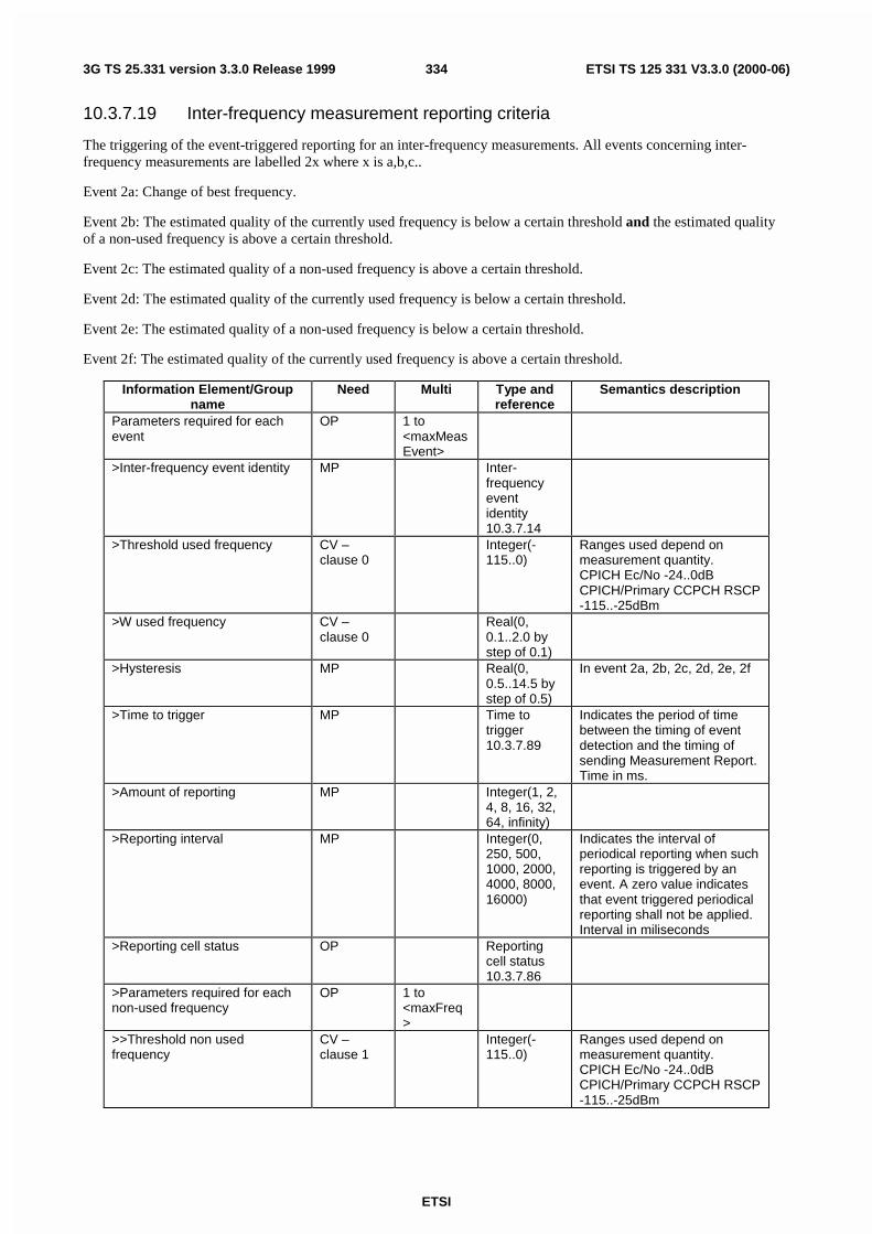
ETSI
ETSI TS 125 331 V3.3.0 (2000-06)3343G TS 25.331 version 3.3.0 Release 1999
10.3.7.19 Inter-frequency measurement reporting criteria
The triggering of the event-triggered reporting for an inter-frequency measurements. All events concerning inter-frequency measurements are labelled 2x where x is a,b,c..
Event 2a: Change of best frequency.
Event 2b: The estimated quality of the currently used frequency is below a certain threshold and the estimated qualityof a non-used frequency is above a certain threshold.
Event 2c: The estimated quality of a non-used frequency is above a certain threshold.
Event 2d: The estimated quality of the currently used frequency is below a certain threshold.
Event 2e: The estimated quality of a non-used frequency is below a certain threshold.
Event 2f: The estimated quality of the currently used frequency is above a certain threshold.
Information Element/Groupname
Need Multi Type andreference
Semantics description
Parameters required for eachevent
OP 1 to<maxMeasEvent>
>Inter-frequency event identity MP Inter-frequencyeventidentity10.3.7.14
>Threshold used frequency CV –clause 0
Integer(-115..0)
Ranges used depend onmeasurement quantity.CPICH Ec/No -24..0dBCPICH/Primary CCPCH RSCP-115..-25dBm
>W used frequency CV –clause 0
Real(0,0.1..2.0 bystep of 0.1)
>Hysteresis MP Real(0,0.5..14.5 bystep of 0.5)
In event 2a, 2b, 2c, 2d, 2e, 2f
>Time to trigger MP Time totrigger10.3.7.89
Indicates the period of timebetween the timing of eventdetection and the timing ofsending Measurement Report.Time in ms.
>Amount of reporting MP Integer(1, 2,4, 8, 16, 32,64, infinity)
>Reporting interval MP Integer(0,250, 500,1000, 2000,4000, 8000,16000)
Indicates the interval ofperiodical reporting when suchreporting is triggered by anevent. A zero value indicatesthat event triggered periodicalreporting shall not be applied.Interval in miliseconds
>Reporting cell status OP Reportingcell status10.3.7.86
>Parameters required for eachnon-used frequency
OP 1 to<maxFreq>
>>Threshold non usedfrequency
CV –clause 1
Integer(-115..0)
Ranges used depend onmeasurement quantity.CPICH Ec/No -24..0dBCPICH/Primary CCPCH RSCP-115..-25dBm
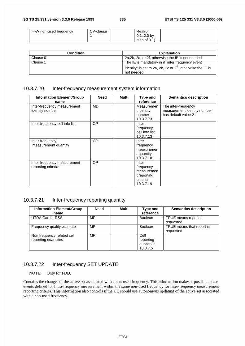
ETSI
ETSI TS 125 331 V3.3.0 (2000-06)3353G TS 25.331 version 3.3.0 Release 1999
>>W non-used frequency CV-clause1
Real(0,0.1..2.0 bystep of 0.1)
Condition ExplanationClause 0 2a,2b, 2d, or 2f, otherwise the IE is not neededClause 1 The IE is mandatory in if "inter frequency event
identity" is set to 2a, 2b, 2c or 2e, otherwise the IE isnot needed
10.3.7.20 Inter-frequency measurement system information
Information Element/Groupname
Need Multi Type andreference
Semantics description
Inter-frequency measurementidentity number
MD Measurement identitynumber10.3.7.73
The inter-frequencymeasurement identity numberhas default value 2.
Inter-frequency cell info list OP Inter-frequencycell info list10.3.7.13
Inter-frequency measurement quantity
OP Inter-frequencymeasurement quantity10.3.7.18
Inter-frequency measurementreporting criteria
OP Inter-frequencymeasurement reportingcriteria10.3.7.19
10.3.7.21 Inter-frequency reporting quantity
Information Element/Groupname
Need Multi Type andreference
Semantics description
UTRA Carrier RSSI MP Boolean TRUE means report isrequested
Frequency quality estimate MP Boolean TRUE means that report isrequested
Non frequency related cellreporting quantities
MP Cellreportingquantities10.3.7.5
10.3.7.22 Inter-frequency SET UPDATE
NOTE: Only for FDD.
Contains the changes of the active set associated with a non-used frequency. This information makes it possible to useevents defined for Intra-frequency measurement within the same non-used frequency for Inter-frequency measurementreporting criteria. This information also controls if the UE should use autonomous updating of the active set associatedwith a non-used frequency.

ETSI
ETSI TS 125 331 V3.3.0 (2000-06)3363G TS 25.331 version 3.3.0 Release 1999
Information Element/groupname
Need Multi Type andreference
Semantics description
UE autonomous update mode MP Enumerated(On,On with noreporting,Off)
Non autonomous update mode CV-Update>Radio link addition information OP 1 to
<maxRL>Radio link addition informationrequired for each RL to add
>>Primary CPICH info MP PrimaryCPICH info10.3.6.51
Note 1
>Radio link removal information OP 1 to<MaxRL>
Radio link removal informationrequired for each RL toremove
>>Primary CPICH info MP PrimaryCPICH info10.3.6.51
Note 1
Condition ExplanationUpdate The IE is mandatory if IE"UE autonomous update
mode" is set to "Off", otherwise the IE is not needed.
NOTE 1: If it is assumed that CPICH downlink scrambling code is always allocated with sufficient reuse distances,CPICH downlink scrambling code will be enough for designating the different radio links.

ETSI
ETSI TS 125 331 V3.3.0 (2000-06)3373G TS 25.331 version 3.3.0 Release 1999
10.3.7.23 Inter-system cell info list
Contains the measurement object information for an inter-system measurement.
Information Element/Groupname
Need Multi Type andreference
Semantics description
Removed inter-system cells OP 1 to<maxCellMeas>
>Inter-system cell id MP Integer(0 ..<maxCellMeas>- 1)
New inter-system cells OP 1 to<maxCellMeas>
>Inter-system cell id MD Integer(0 ..<maxCellMeas>- 1)
The first inter-system cell inthe list corresponds tointer-system cell id 0, thesecond corresponds tointer-system cell id 1 etc.
>CHOICE Radio AccessTechnology
MP At least one spare choice,Criticality: Reject, isneeded.
>>GSM>>>Qoffsets,n MD Integer (-50..50) Default value if the value of
the previous Qoffsets,n inthe list (NOTE: the firstoccurrence is then MP)
>>>HCS Neighbouring cellinformation
OP HCSNeighbouringcell information10.3.7.11
>>>Qrxlevmin MP>>>Maximum allowed UL TXpower
MP Maximumallowed UL TXpower 10.3.6.33
>>> BSIC MP BSIC 10.3.8.2>>>BCCH ARFCN MP Integer (0..1023) GSM TS 04.18>>>Output power OP>>IS-2000>>>System specificmeasurement info
enumerated(frequency,timeslot, colourcode, outputpower, PNoffset)
For IS-2000, use fieldsfrom TIA/EIA/IS-2000.5,Section 3. 7.3.3.2.27,Candidate FrequencyNeighbor List Message
10.3.7.24 Inter-system event identity
Information Element/Groupname
Need Multi Type andreference
Semantics description
Inter-system event identity MP Enumerated(3a, 3b, 3c,3d)

ETSI
ETSI TS 125 331 V3.3.0 (2000-06)3383G TS 25.331 version 3.3.0 Release 1999
10.3.7.25 Inter-system info
Inter-system info defines the target system for redirected cell selection.
Information Element/Groupname
Need Multi Type andreference
Semantics description
Inter-system info MP Enumerated(GSM)
At least 1 spare value,criticality = reject, required
10.3.7.26 Inter-system measured results list
Information Element/Groupname
Need Multi Type andreference
Semantics description
Inter-system measurementresults
OP 1 to<maxOtherRAT>
>CHOICE system At least one spare value,criticality = reject, required
>>GSM>>>Frequency MP>>>GSM carrier RSSI OP bit string(6) RXLEV GSM TS 05.08>>>Pathloss OP Integer(46..1
58)In dB
>>>BSIC OP BSIC10.3.8.2
>>>Observed time difference toGSM cell
OP Observedtimedifference toGSM cell10.3.7.77

ETSI
ETSI TS 125 331 V3.3.0 (2000-06)3393G TS 25.331 version 3.3.0 Release 1999
10.3.7.27 Inter-system measurement
Information Element/Groupname
Need Multi Type andreference
Semantics description
Inter-system cell info list OP Inter-systemcell info list10.3.7.23
Measurement object
Inter-system measurement quantity
OP Inter-systemmeasurement quantity10.3.7.29
Inter-system reporting quantity OP Inter-systemreportingquantity10.3.7.32
Reporting cell status CV-reporting
Reportingcell status10.3.7.86
CHOICE report criteria MP>Inter-system measurement reporting criteria
Inter-systemmeasurement reportingcriteria10.3.7.30
>Periodical reporting criteria Periodicalreportingcriteria10.3.7.78
>No reporting (no data)Chosen when thismeasurement only is used asadditional measurement toanother measurement
Condition Explanationreporting This IE is optional if the CHOICE "report criteria" is
equal to "periodical reporting criteria" or "Noreporting", otherwise the IE is not needed
10.3.7.28 Inter-system measurement event results
This IE contains the measurement event results that are reported to UTRAN for inter-system measurements.
Information Element/Groupname
Need Multi Type andreference
Semantics description
Inter-system event identity MP Inter-systemeventidentity10.3.7.24
Cells to report MP 1 to<maxCellMeas>
>Frequency MP>BSIC MP BSIC
10.3.8.2

ETSI
ETSI TS 125 331 V3.3.0 (2000-06)3403G TS 25.331 version 3.3.0 Release 1999
10.3.7.29 Inter-system measurement quantity
The quantity the UE shall measure in case of inter-system measurement. It also includes the filtering of themeasurements.
Information Element/Groupname
Need Multi Type andreference
Semantics description
Measurement quantity forUTRAN quality estimate
MP Intra-frequencymeasurement quantity10.3.7.38
CHOICE system MP>GSM>>Measurement quantity MP Enumerated(
GSM CarrierRSSI,Pathloss)
>>Filter coefficient MP Filtercoefficient10.3.7.9
>>BSIC verification required MP Enumerated(required, notrequired)
Note 1
>IS2000>>TADD Ec/I0 MP Integer(0..63
)Admission criteria forneighbours, see subclause2.6.6.2.6 of TIA/EIA/IS-2000.5
>>TCOMP Ec/I0 MP Integer(0..15)
Admission criteria forneighbours, see subclause2.6.6.2.5.2 of TIA/EIA/IS-2000.5
>>SOFT SLOPE OP Integer(0..63)
Admission criteria forneighbours, see subclause2.6.6.2.3 and 2.6.6.2.5.2 ofTIA/EIA/IS-2000.5
>>ADD_INTERCEPT OP Integer(0..63)
Admission criteria forneighbours, see subclause2.6.6.2.5.2 of TIA/EIA/IS-2000.5
NOTE 1: The possibility to use this IE is dependant on comments from SMG2.
Also, this IE must be set to "required" if IE "Observed time difference to GSM cell" in IE "Inter-system reportingquantity "is set to "true".

ETSI
ETSI TS 125 331 V3.3.0 (2000-06)3413G TS 25.331 version 3.3.0 Release 1999
10.3.7.30 Inter-system measurement reporting criteria
The triggering of the event-triggered reporting for an inter-system measurement. All events concerning inter-systemmeasurements are labelled 3x where x is a,b,c..
Event 3a: The estimated quality of the currently used UTRAN frequency is below a certain threshold and the estimatedquality of the other system is above a certain threshold.
Event 3b: The estimated quality of other system is below a certain threshold.
Event 3c: The estimated quality of other system is above a certain threshold.
Event 3d: Change of best cell in other system.
Information Element/Groupname
Need Multi Type andreference
Semantics description
Parameters required for eachevent
OP 1 to<maxMeasEvent>
>Inter-system event identity MP Inter-systemeventidentity10.3.7.24
>Threshold own system CV –clause 0
>W CV –clause 0
In event 3a
>Threshold other system CV –clause 1
In event 3a, 3b, 3c
>Hysteresis MP>Time to trigger MP Time to
trigger10.3.7.89
Indicates the period of timebetween the timing of eventdetection and the timing ofsending Measurement Report.
>Amount of reporting MP>Reporting interval MP Indicates the interval of
periodical reporting when suchreporting is triggered by anevent. A zero value indicatesthat event triggered periodicalreporting shall not be applied.
>Reporting cell status OP Reportingcell status10.3.7.86
Condition ExplanationClause 0 The IE is mandatory if " Inter-system event identity" is
set to "3a", otherwise the IE is not neededClause 1 The IE is mandatory if " Inter-system event identity" is
set to 3a, 3b or 3c, otherwise the IE is not needed

ETSI
ETSI TS 125 331 V3.3.0 (2000-06)3423G TS 25.331 version 3.3.0 Release 1999
10.3.7.31 Inter-system measurement system information
Information Element/Groupname
Need Multi Type andreference
Semantics description
Inter-system measurement identitynumber
MD Measurement identitynumber10.3.7.73
The inter-systemmeasurement identity numberhas default value 3.
Inter-system cell info list OP Inter-systemcell info list10.3.7.23
Inter-system measurement quantity
OP Inter-systemmeasurement quantity10.3.7.29
10.3.7.32 Inter-system reporting quantity
For all boolean types TRUE means inclusion in the report is requested.
Information Element/Groupname
Need Multi Type andreference
Semantics description
UTRAN estimated quality MP BooleanCHOICE system MP At least one spare choice,
criticality = reject, required>GSM>>Pathloss MP Boolean>>Observed time difference toGSM cell
MP Boolean
>>GSM Carrier RSSI MP Boolean>>BSIC MP Boolean
10.3.7.33 Intra-frequency cell info list
Contains the measurement object information for an intra-frequency measurement.
Information Element/Groupname
Need Multi Type andreference
Semantics description
Removed intra-frequency cells OP 1 to<maxCellMeas>
>Intra-frequency cell id MP Integer(0 ..<maxCellMeas> - 1)
New intra-frequency cell OP 1 to<maxCellMeas>
This information element mustbe present when "Intra-frequency cell info list" isincluded in the systeminformation
>Intra-frequency cell id MD Integer(0 ..<maxCellMeas> - 1)
The first intra-frequency cell inthe list corresponds to intra-frequency cell id 0, the secondcorresponds to intra-frequencycell id 1 etc.
>Cell info MP Cell info10.3.7.2

ETSI
ETSI TS 125 331 V3.3.0 (2000-06)3433G TS 25.331 version 3.3.0 Release 1999
10.3.7.34 Intra-frequency event identity
Information Element/Groupname
Need Multi Type andreference
Semantics description
Intra-frequency event identity MP Enumerated(1a,1b,1c,1d,1e,1f,1g,1h,1I)
10.3.7.35 Intra-frequency measured results list
Information Element/Groupname
Need Multi Type andreference
Semantics description
Intra-frequency measuredresults
OP 1 to<maxCellMeas>
>Cell measured results MP Cellmeasuredresults10.3.7.3
10.3.7.36 Intra-frequency measurement
Information Element/Groupname
Need Multi Type andreference
Semantics description
Intra-frequency cell info list OP Intra-frequencycell info list10.3.7.33
Measurement objectNot included for measurementof detected set.
Intra-frequency measurement quantity
OP Intra-frequencymeasurement quantity10.3.7.38
Intra-frequency reporting quantity OP Intra-frequencyreportingquantity10.3.7.41
Reporting cell status CV-reporting
Reportingcell status10.3.7.86
Measurement validity OP Measurement validity10.3.7.76
CHOICE report criteria MP>Intra-frequency measurement reporting criteria
Intra-frequencymeasurement reportingcriteria10.3.7.39
>Periodical reporting criteria Periodicalreportingcriteria10.3.7.78
>No reporting (no data)Chosen when thismeasurement only is used asadditional measurement toanother measurement

ETSI
ETSI TS 125 331 V3.3.0 (2000-06)3443G TS 25.331 version 3.3.0 Release 1999
Condition Explanationreporting This IE is optional if the CHOICE "report criteria" is
equal to "periodical reporting criteria" or "Noreporting", otherwise the IE is not needed
10.3.7.37 Intra-frequency measurement event results
This IE contains the measurement event results that are reported to UTRAN for intra-frequency measurements.
Information Element/Groupname
Need Multi Type andreference
Semantics description
Intra-frequency event identity MP Intra-frequencyeventidentity10.3.7.34
Cell measured event results MP Cellmeasuredevent results10.3.7.4
10.3.7.38 Intra-frequency measurement quantity
The quantity the UE shall measure in case of intra-frequency measurement. It also includes the filtering of themeasurements.
Information Element/Groupname
Need Multi Type andreference
Semantics description
Filter coefficient MP Filtercoefficient10.3.7.9
CHOICE mode MP>FDD>>Measurement quantity MP Enumerated(C
PICH Ec/N0,CPICH RSCP,Pathloss,UTRA CarrierRSSI)
Pathloss=Primary CPICH Txpower-CPICH RSCP
If used in Inter systemmeasurement quantity onlyEc/N0 an RSCP is allowed.If used in inter-frequencymeasurement quantity RSSIis not allowed.
>TDD>>Measurement quantity list MP 1 to 4>>>Measurement quantity MP Enumerated(Pr
imary CCPCHRSCP,Pathloss,Timeslot ISCP,UTRA CarrierRSSI)
Pathloss=Primary CCPCHTx power-Primary CCPCHRSCPIf used in inter-frequencymeasurement quantity RSSIis not allowed.

ETSI
ETSI TS 125 331 V3.3.0 (2000-06)3453G TS 25.331 version 3.3.0 Release 1999
10.3.7.39 Intra-frequency measurement reporting criteria
The triggering of the event-triggered reporting for an intra-frequency measurement. All events concerning intra-frequency measurements are labelled 1x where x is a, b, c….
Event 1a: A Primary CPICH enters the Reporting Range (FDD only).
Event 1b: A Primary CPICH leaves the Reporting Range (FDD only).
Event 1c: A Non-active Primary CPICH becomes better than an active Primary CPICH (FDD only).
Event 1d: Change of best cell [Note 1] (FDD only).
Event 1e: A Primary CPICH becomes better than an absolute threshold (FDD only).
Event 1f: A Primary CPICH becomes worse than an absolute threshold (FDD only).
Event 1g: Change of best cell in TDD.
Event 1h: Timeslot ISCP below a certain threshold (TDD only).
Event 1i: Timeslot ISCP above a certain threshold (TDD only).
Information Element/Groupname
Need Multi Type andreference
Semantics description
Parameters required for eachevent
OP 1 to<maxMeasEvent>
> Intra-frequency event identity MP Intra-frequencyeventidentity10.3.7.34
>Triggering condition CV –clause 0
Enumerated(Active setcells,Monitoredset cells,Active setcells andmonitoredset cells)
Indicates which cells that cantrigger the event
>Reporting Range CV –clause 2
Real(0..14.5by step of0.5)
In dB. In event 1a,1b.
>Cells forbidden to affectReporting range
CV –clause 1
1 to<maxCellMeas>
In event 1a,1b
>>CHOICE mode MP>>>FDD>>>>Primary CPICH info MP Primary
CPICH info10.3.6.51
>>>TDD>>>>Primary CCPCH info MP Primary
CCPCH info10.3.6.49
>W CV –clause 2
Real(0.0..2.0by step of0.1)
>Hysteresis MP Real(0..7.5by step of0.5)
In dB.

ETSI
ETSI TS 125 331 V3.3.0 (2000-06)3463G TS 25.331 version 3.3.0 Release 1999
> Threshold used frequency CV-clause3
Integer(-125..165)
Range used depend onmeasurement quantity.CPICH RSCP -115 .. -40dBmCPICH Ec/No -24..0 dBPathloss 30..165dBISCP -125..-30 dBm
>Reporting deactivation threshold
CV –clause 4
Integer(0, 1,2, 3, 4, 5, 6,7)
In event 1aIndicates the maximumnumber of cells allowed in theactive set in order for event1a to occur.0 means not applicable.
>Replacement activation threshold
CV -clause 5
Integer(0, 1,2, 3, 4, 5, 6,7)
In event 1cIndicates the minimumnumber of cells allowed in theactive set in order for event1c to occur.0 means not applicable
>Time to trigger MP Time totrigger10.3.7.89
Indicates the period of timebetween the timing of eventdetection and the timing ofsending MeasurementReport. Time in ms
>Amount of reporting MP Integer(1, 2,4, 8, 16, 32,64, Infinity)
Measurement is "released"after the indicated amount ofreporting from the UE itself.
>Reporting interval MP Integer(0,250, 500,1000, 2000,4000, 8000,16000)
Indicates the interval ofperiodical reporting whensuch reporting is triggered byan event. Interval inmiliseconds.0 means no periodicalreporting
>Reporting cell status OP Reportingcell status10.3.7.86
Condition ExplanationClause 0 The IE is mandatory if "Intra-frequency event identity"
is set to "1a","1b", "1e" or "1f", otherwise the IE is notneeded
Clause 1 The IE is optional if "Intra-frequency event identity" isset to "1a" or "1b", otherwise the IE is not needed
Clause 2 The IE is mandatory if "Intra-frequency event identity"is set to "1a" or "1b", otherwise the IE is not needed
Clause 3 The IE is mandatory if "Intra-frequency event identity"is set to , "1e", "1f", "1h", "1i" or "1j", otherwise the IEis not needed
Clause 4 The IE is mandatory if "Intra-frequency event identity"is set to "1a", otherwise the IE is not needed
Clause 5 The IE is mandatory if "Intra-frequency event identity"is set to "1c", otherwise the IE is not needed
Clause 6 The IE is mandatory if "Intra-frequency event identity"is set to "1e" or "1f".
NOTE 1: When best PCCPCH in active set changes, all active cells are reported.

ETSI
ETSI TS 125 331 V3.3.0 (2000-06)3473G TS 25.331 version 3.3.0 Release 1999
10.3.7.40 Intra-frequency measurement system information
Information Element/Groupname
Need Multi Type andreference
Semantics description
Intra-frequency measurementidentity number
MD Measurement identitynumber10.3.7.73
The intra-frequencymeasurement identity numberhas default value 1.
Intra-frequency cell info list OP Intra-frequencycell info list10.3.7.33
Intra-frequency measurement quantity
OP Intra-frequencymeasurement quantity10.3.7.38
Intra-frequency reporting quantity for RACH Reporting
OP Intra-frequencyreportingquantity forRACHReporting10.3.7.42
Maximum number of reported cells on RACH
OP Maximumnumber ofreportedcells onRACH10.3.7.68
Reporting information for stateCELL_DCH
OP Reportinginformationfor stateCELL_DCH10.3.7.87
Note 1
NOTE 1: The reporting of intra-frequency measurements is activated when state CELL_DCH is entered.
10.3.7.41 Intra-frequency reporting quantity
Contains the reporting quantity information for an intra-frequency measurement.
Information Element/Groupname
Need Multi Type andreference
Semantics description
Reporting quantities for activeset cells
MP Cellreportingquantities10.3.7.5
Reporting quantities formonitored set cells
MP Cellreportingquantities10.3.7.5
Reporting quantities for detectedset cells
OP Cellreportingquantities10.3.7.5

ETSI
ETSI TS 125 331 V3.3.0 (2000-06)3483G TS 25.331 version 3.3.0 Release 1999
10.3.7.42 Intra-frequency reporting quantity for RACH reporting
Contains the reporting quantity information for an intra-frequency measurement report, which is sent on the RACH.
Information Element/Groupname
Need Multi Type andreference
Semantics description
SFN-SFN observed timedifference
MP Enumerated(No report,type 1, type2)
CHOICE mode MP>FDD>>Reporting quantity MP Enumerated(
CPICHEc/N0,CPICHRSCP,Pathloss, Noreport)
>TDD>>Reporting quantity list MP 1 to 2>>>Reporting quantity MP Enumerated(
TimeslotISCP,PrimaryCCPCHRSCP, Noreport)

ETSI
ETSI TS 125 331 V3.3.0 (2000-06)3493G TS 25.331 version 3.3.0 Release 1999
10.3.7.43 LCS Error
Information Element/Groupname
Need Multi Type andReference
Semantics description
Error reason MP Enumerated(There werenot enoughcells to bereceivedwhenperformingmobilebasedOTDOA-IPDL.There werenot enoughGPSsatellites tobe received,whenperformingUE-basedGPSlocation.Locationcalculationassistancedatamissing.Requestedmethod notsupported.Undefinederror.Locationrequestdenied bythe user.Locationrequest notprocessedby the userand timeout.
Additional Assistance Data OP structure andencoding asfor the GPSAssistanceData IE inGSM 09.31excludingthe IEI andlength octets
This field is optional. Itspresence indicates that thetarget UE will retain assistancedata already sent by theSRNC. The SRNC may sendfurther assistance data for anynew location attempt but neednot resend previousassistance data. The field maycontain the following:GPS Assistance Data
necessary additional GPSassistance data
10.3.7.44 LCS GPS acquisition assistance
The Acquisition Assistance field of the GPS Assistance Data Information Element contains parameters that enable fastacquisition of the GPS signals in network-based GPS positioning. Essentially, these parameters describe the range andderivatives from respective satellites to the Reference Location at the Reference Time.

ETSI
ETSI TS 125 331 V3.3.0 (2000-06)3503G TS 25.331 version 3.3.0 Release 1999
Information Element/Groupname
Need Multi Type andReference
Semantics description
CHOICE Reference Time>UTRAN reference time GPS Time of Week counted in
microseconds, given as GPSTOW in milliseconds and GPSTOW remainder inmicroseconds,UTRAN reference time = 1000* GPS TOW msec + GPSTOW rem usec
>>GPS TOW msec MP Integer(0..6.
048*108-1)
GPS Time of Week inmiliseconds (rounded down tothe nearest milisecond unit)
>>GPS TOW rem usec MP Integer(0..999)
GPS Time of Week inmicroseconds MOD 1000.
>>SFN MP Integer(0..4095)
>GPS reference time only>>GPS TOW MP Integer(0..6.
048*108-1)
GPS Time of Week inmilliseconds (rounded down tothe nearest millisecond unit).
Satellite information MP 1 to<maxSat>
>SatID MP Enumerated(0..63)
Identifies the satellites
>Doppler (0th order term) MP Integer(-2048..2047)
Hz, scaling factor 2.5
>Extra Doppler OP
>>Doppler (1st order term) MP Integer(-42..21)
Scaling factor 1/42
>>Doppler Uncertainty MP Real(12.5,25,50,100,200)
Hz
>Code Phase MP Integer(0..1022)
Chips, specifies the centre ofthe search window
>Integer Code Phase MP Integer(0..19)
1023 chip segments
>GPS Bit number MP Integer(0..3) Specifies GPS bit number (201023 chip segments)
>Code Phase Search Window MP Integer(1023,1,2,3,4,6,8,12,16,24,32,48,64,96,128,192)
Specifies the width of thesearch window.
>Azimuth and Elevation OP>>Azimuth MP Integer(0..31
)Degrees, scale factor 11.25
>>Elevation MP Integer(0..7) Degrees, scale factor 11.25
CHOICE Reference time Condition under which the given reference time ischosen
UTRAN reference time The reference time is relating GPS time to UTRANtime (SFN)
GPS reference time only The time gives the time for which the locationestimate is valid
10.3.7.45 LCS GPS almanac
These fields specify the coarse, long-term model of the satellite positions and clocks. With one exception (δi), theseparameters are a subset of the ephemeris and clock correction parameters in the Navigation Model, although withreduced resolution and accuracy. The almanac model is useful for receiver tasks that require coarse accuracy, such asdetermining satellite visibility. The model is valid for up to one year, typically. Since it is a long-term model, the fieldshould be provided for all satellites in the GPS constellation.

ETSI
ETSI TS 125 331 V3.3.0 (2000-06)3513G TS 25.331 version 3.3.0 Release 1999
Information Element/Groupname
Need Multi Type andReference
Semantics description
WNa MP Bit string(8)Satellite information MP 1 to
<maxSat>>SatID MP Enumerated(
0..63)Satellite ID
>e MP Bit string(16)>toa MP Bit string(8)
>δi MP Bit string(16)>OMEGADOT MP Bit string(16)>SV Health MP Bit string(8)
>A1/2 MP Bit string(24)
>OMEGA0 MP Bit string(24)>M0 MP Bit string(24)
>ω MP Bit string(24)>af0 MP Bit string(11)>af1 MP Bit string(11)
10.3.7.46 LCS GPS assistance data
The GPS Assistance Data element contains a single GPS assistance message that supports both UE-assisted and UE-based GPS methods. An Integrity Monitor (IM) shall detect unhealthy (e.g., failed/failing) satellites and also shallinform users of measurement quality in DGPS modes when satellites are healthy. Excessively large pseudo range errors,as evidenced by the magnitude of the corresponding DGPS correction, shall be used to detect failed satellites.Unhealthy satellites should be detected within 10 seconds of the occurrence of the satellite failure. When unhealthy(e.g., failed/failing) satellites are detected, the assistance and/or DGPS correction data shall not be supplied for thesesatellites. When the error in the IM computed position is excessive for solutions based upon healthy satellites only,DGPS users shall be informed of measurement quality through the supplied UDRE values.
NOTE: Certain types of GPS Assistance data may be derived, wholly or partially, from other types of GPSAssistance data.

ETSI
ETSI TS 125 331 V3.3.0 (2000-06)3523G TS 25.331 version 3.3.0 Release 1999
Information Element/Groupname
Need Multi Type andReference
Semantics description
LCS GPS reference time OP LCS GPSreferencetime10.3.7.53
LCS GPS reference location OP Ellipsoidpoint withaltitudedefined in23.032
The Reference Location fieldcontains a 3-D location withoutuncertainty specified as per23.032. The purpose of thisfield is to provide the UE with apriori knowledge of its locationin order to improve GPSreceiver performance.
LCS GPS DGPS corrections OP LCS GPSDGPScorrections10.3.7.48
LCS GPS navigation model OP LCS GPSnavigationmodel10.3.7.51
LCS GPS ionospheric model OP LCS GPSionosphericmodel10.3.7.49
LCS GPS UTC model OP LCS GPSUTC model10.3.7.54
LCS GPS almanac OP LCS GPSalmanac10.3.7.45
LCS GPS acquisition assistance OP LCS GPSacquisitionassistance10.3.7.44
LCS GPS real-time integrity OP LCS GPSreal-timeintegrity10.3.7.52
10.3.7.47 LCS GPS assistance for SIB
The LCS GPS Assistance ciphering for SIB IE contains information for GPS differential corrections, ephemeris andclock corrections, as well as Almanac and other data..
Information Element/Groupname
Need Multi Type andReference
Semantics description
Cipher On/Off OP>Ciphering Key Flag MP Bitstring(1) See note 1>Ciphering Serial Number OP Integer(0..65
535)The serial number used in theDES ciphering algorithm
NOTE 1: The UE always receives two (2) cipher keys during the location update procedure. One of the keys istime-stamped to be current one and the other is time-stamped to be the next one. Thus, the UE always hastwo cipher keys in memory. The Cipher Key Change Indicator in this broadcast message instructs the UEwhether to use current or next cipher key for deciphering the received broadcast message. The UE shallinterpret this IE as follows:
- Ciphering Key Flag(previous message) = Ciphering Key Flag(this message) => Deciphering Key not changed
- Ciphering Key Flag(previous message) <> Ciphering Key Flag(this message) => Deciphering Key changed

ETSI
ETSI TS 125 331 V3.3.0 (2000-06)3533G TS 25.331 version 3.3.0 Release 1999
10.3.7.48 LCS GPS DGPS corrections
These fields specify the DGPS corrections to be used by the UE.
Information Element/Groupname
Need Multi Type andReference
Semantics description
GPS TOW MP Integer(0..604799)
Seconds. This field indicatesthe baseline time for which thecorrections are valid.
Status/Health MP Enumerated(UDRE scale1.0, UDREscale 0.75,UDRE scale0.5, UDREscale 0.3,UDRE scale0.2, UDREscale 0.1, nodata, invaliddata)
This field indicates the statusof the differential corrections
Satellite information MP 1 to<maxSat>
>SatID MP Enumerated(0..63)
Satellite ID
>IODE MP Bit string(8) This IE is the sequencenumber for the ephemeris forthe particular satellite. The UEcan use this IE to determine ifnew ephemeris is used forcalculating the corrections thatare provided in the broadcastmessage. This eight-bit IE isincremented for each new setof ephemeris for the satelliteand may occupy the numericalrange of [0, 239] during normaloperations. See [13] for details
>UDRE MP Enumerated(UDRE ≤ 1.0m,1.0m <UDRE ≤4.0m,4.0m <UDRE ≤8.0m,8.0m <UDRE)
User Differential Range Error.This field provides an estimateof the uncertainty (1-σ) in thecorrections for the particularsatellite. The value in this fieldshall be multiplied by theUDRE Scale Factor in thecommon CorrectionsStatus/Health field todetermine the final UDREestimate for the particularsatellite. See [13] for details
>PRC MP Integer(-2047..2047)
Scaling factor 0.32 meters See(different from [13])
>RRC MP Integer(-127.. 127)
Scaling factor 0.032meters/sec (different from [13])
>Delta PRC2 MP Integer(-127..127)
Meters. The difference in thepseudorange correctionbetween the satellite'sephemeris identified by IODEand the previous ephemeristwo issues ago IODE –2.

ETSI
ETSI TS 125 331 V3.3.0 (2000-06)3543G TS 25.331 version 3.3.0 Release 1999
>Delta RRC2 MP Integer(-7..7) Scaling factor 0.032meters/sec. The difference inthe rate of the change of thepseudorange correctionbetween the satellite'sephemeris identified by IODEand the previous ephemeristwo issues ago IODE –2.
>Delta PRC3 MP Integer(-127..127)
Meters. The difference in thepseudorange correctionbetween the satellite'sephemeris identified by IODEand the previous ephemeristhree issues ago IODE –3.
>Delta RRC3 MP Integer(-7..7) Scaling factor 0.032meters/sec. The difference inthe rate of the change of thepseudorange correctionbetween the satellite'sephemeris identified by IODEand the previous ephemeristhree issues ago IODE –3.
NOTE: Each UDRE value shall be adjusted based on the operation of an Integrity Monitor (IM) function whichexists at the network (SRNC, GPS server, or reference GPS receiver itself). Positioning errors derived atthe IM which are excessive relative to DGPS expected accuracy levels shall be used to scale the UDREvalues to produce consistency.
10.3.7.49 LCS GPS ionospheric model
The Ionospheric Model contains fields needed to model the propagation delays of the GPS signals through theionosphere. Proper use of these fields allows a single-frequency GPS receiver to remove approximately 50% of theionospheric delay from the range measurements. The Ionospheric Model is valid for the entire constellation and changesslowly relative to the Navigation Model.
Information Element/Groupname
Need Multi Type andReference
Semantics description
α0 MP Bit string(8)
α1 MP Bit string(8)
α2 MP Bit string(8)
α3 MP Bit string(8)
β0 MP Bit string(8)
β1 MP Bit string(8)
β2 MP Bit string(8)
β3 MP Bit string(8)
10.3.7.50 LCS GPS measurement
The purpose of the GPS Measurement Information element is to provide GPS measurement information from the UE tothe SRNC. This information includes the measurements of code phase and Doppler, which enables the network-basedGPS method where the position is computed in the SRNC.

ETSI
ETSI TS 125 331 V3.3.0 (2000-06)3553G TS 25.331 version 3.3.0 Release 1999
Information Element/Groupname
Need Multi Type andReference
Semantics description
Reference SFN OP Integer(0..4095)
The SFN for which the locationis valid
GPS TOW msec MP Integer(0..6.
048*108-1)
GPS Time of Week inmilliseconds (rounded down tothe nearest millisecond unit).This time is the GPS TOWmeasured by the UE. If theReference SFN field is presentit is the ms flank closest to thebeginning of that frame.GPS Time of Week inmicroseconds = 1000 * GPSTOW msec + GPS TOW remusec
GPS TOW rem usec CV-capabilityandrequest
Integer(0..999)
GPS Time of Week inmicroseconds MOD 1000.
Measurement Parameters MP 1 to<maxSat>
>Satellite ID MP Enumerated(0..63)
>C/No MP Integer(0..63)
the estimate of the carrier-to-noise ratio of the receivedsignal from the particularsatellite used in themeasurement. It is given inwhole dBs. Typical levelsobserved by UE-based GPSunits will be in the range of 20– 50 dB.
>Doppler MP Integer(-32768..32768)
Hz, scale factor 0.2.
>Whole GPS Chips MP Integer(0..1023)
Unit in GPS chips
>Fractional GPS Chips MP Integer(0..(210-1))
Scale factor 2-10
>Multipath Indicator MP Enumerated(NM, low,medium,high)
See note 1
>Pseudorange RMS Error MP Enumerated(range index0..rangeindex 63)
See note 2
Condition ExplanationCapability and request This field is included only if the UE has this capability
and if it was requested in the LCS reporting quantity
NOTE 1: The following table gives the mapping of the multipath indicator field.
Value Multipath IndicationNM Not measuredLow MP error < 5mMedium 5m < MP error < 43mHigh MP error > 43m
NOTE 2: The following table gives the bitmapping of the Pseudorange RMS Error field.

ETSI
ETSI TS 125 331 V3.3.0 (2000-06)3563G TS 25.331 version 3.3.0 Release 1999
RangeIndex
Mantissa Exponent Floating-Point value, xi Pseudorangevalue, P
0 000 000 0.5 P < 0.5
1 001 000 0.5625 0.5 <= P < 0.5625
I X Y 0.5 * (1 + x/8) * 2y xi-1 <= P < xi
62 110 111 112 104 <= P < 112
63 111 111 -- 112 <= P
10.3.7.51 LCS GPS navigation model
This IE contain information required to manage the transfer of precise navigation data to the GPS-capable UE. Thisinformation includes control bit fields as well as satellite ephemeris and clock corrections.

ETSI
ETSI TS 125 331 V3.3.0 (2000-06)3573G TS 25.331 version 3.3.0 Release 1999
Information Element/Groupname
Need Multi Type andReference
Semantics description
N_SAT MP Integer(1..16)
The number of satellitesincluded in this IE
Satellite information MP 1 to<maxSat>
>SatID MP Enumerated(0..63)
Satellite ID
>Satellite Status MP Enumerated(NS_NN,ES_SN,ES_NN,REVD)
See note 1
>C/A or P on L2 MP Bit string(2) Standard formats as defined in[12]
>URA Index MP Bit string(4)>SV Health MP Bit string(6)>IODC MP Bit
string(10(1))
>L2 P Data Flag MP Bit string(1)>SF 1 Reserved MP Bit string(87)>TGD MP Bit string(8)>toc MP Bit
string(16(1))
>af2 MP Bit string(8)>af1 MP Bit string(16)>af0 MP Bit string(22)>Crs MP Bit string(16)
>∆n MP Bit string(16)>M0 MP Bit string(32)>Cuc MP Bit string(16)>e MP Bit
string(32(1))
>Cus MP Bit string(16)
>(A)1/2 MP Bit
string(32(1))
>toe MP Bit
string(16(1))
>Fit Interval Flag MP Bit string(1)>AODO MP Bit string(5)>Cic MP Bit string(16)>OMEGA0 MP Bit string(32)>Cis MP Bit string(16)>i0 MP Bit string(32)>Crc MP Bit string(16)>ω MP Bit string(32)>OMEGAdot MP Bit string(24)>Idot MP Bit string(14)
NOTE 1: The UE shall interpret enumerated symbols as follows.
Symbol InterpretationNS_NN New satellite, new Navigation ModelES_SN Existing satellite, same Navigation ModelES_NN Existing satellite, new Navigation ModelREVD Reserved

ETSI
ETSI TS 125 331 V3.3.0 (2000-06)3583G TS 25.331 version 3.3.0 Release 1999
Condition Explanationstatus Group Included unless status is ES_SN
10.3.7.52 LCS GPS real-time integrity
Contains parameters that describe the real-time status of the GPS constellation. Primarily intended for non-differentialapplications, the real-time integrity of the satellite constellation is of importance as there is no differential correctiondata by which the mobile can determine the soundness of each satellite signal. The Real-Time GPS Satellite Integritydata communicates the health of the constellation to the mobile in real-time. The satellites identified in this IE shouldnot be used for position fixes at the moment.
Information Element/Groupname
Need Multi Type andReference
Semantics description
Satellite information OP 1 to<maxSat>
N_BAD_SAT=the number ofbad satellites included in thisIE
>BadSatID MP Enumerated(0..63)
Satellite ID
10.3.7.53 LCS GPS reference time
Information Element/Groupname
Need Multi Type andReference
Semantics description
GPS Week MP Integer(0..1023)
GPS TOW msec MP Integer(0..6.
048*108-1)
GPS Time of Week inmilliseconds (rounded down tothe nearest millisecond unit).GPS Time of Week inmicroseconds = 1000 * GPSTOW msec + GPS TOW remusec
GPS TOW rem usec MP Integer(0..999)
GPS Time of Week inmicroseconds MOD 1000.
SFN MP Integer(0..4095)
The SFN which the GPS TOWtime stamps
GPS TOW Assist OP 1 to<maxSat>
Fields to help the UE withtime-recovery (needed topredict satellite signal)
>SatID MP Enumerated(0..63)
Identifies the satellite for whichthe corrections are applicable
>TLM Message MP Bit string(14) A 14-bit value representing theTelemetry Message (TLM)being broadcast by the GPSsatellite identified by theparticular SatID, with the MSBoccurring first in the satellitetransmission.
>Anti-Spoof MP Boolean The Anti-Spoof and Alert flagsthat are being broadcast bythe GPS satellite identified bySatID.
>Alert MP Boolean>TLM Reserved MP Bit string(2) Two reserved bits in the TLM
Word being broadcast by theGPS satellite identified bySatID, with the MSB occurringfirst in the satellitetransmission.

ETSI
ETSI TS 125 331 V3.3.0 (2000-06)3593G TS 25.331 version 3.3.0 Release 1999
10.3.7.54 LCS GPS UTC model
The UTC Model field contains a set of parameters needed to relate GPS time to Universal Time Coordinate (UTC).
Information Element/Groupname
Need Multi Type andReference
Semantics description
A1 MP Bit string(24)A0 MP Bit string(32)tot MP Bit string(8)∆tLS MP Bit string(8)WNt MP Bit string(8)WNLSF MP Bit string(8)DN MP Bit string(8)∆tLSF MP Bit string(8)
10.3.7.55 LCS IPDL parameters
Information Element/Groupname
Need Multi Type andReference
Semantics description
IP spacing MP Integer(5,7,10,15,20,30,40,50)
The IPs are repeated every IPspacing frame.
IP length MP Integer(5,10) The length in symbols of theidle periods
IP offset MP Integer(0..9) Relates the BFN and SFN,should be same as T_celldefined in 25.402
Seed MP Integer(0..63)
Seed used to start the randomnumber generator
Burst mode parameters OP>Burst Start MP Integer(0..15
)The frame number where the
1st Idle Period Burst occurswithin an SFN cycle. Scalingfactor 256.
>Burst Length MP Integer(10..25)
Number of Idle Periods in a'burst' of Idle Periods
>Burst freq MP Integer(1..16)
Number of 10ms framesbetween consecutive IdlePeriod bursts. Scaling factor256.
The function IP_position(x) described below yields the position of the xth Idle Period relative to a) the start of the SFNcycle when continuous mode or b) the start of a burst when in burst mode. The operator "%" denotes the modulooperator. Regardless of mode of operation, the Idle Period pattern is reset at the start of every SFN cycle. Continuousmode can be considered as a specific case of the burst mode with just one burst spanning the whole SFN cycle. Notealso that x will be reset to x=1 for the first idle period in a SFN cycle for both continuous and burst modes and will also,in the case of burst mode, be reset for the first Idle Period in every burst.
Max_dev=150-IP length
rand(x)= (106.rand(x-1) + 1283)mod6075,
rand(0)=seed
IP_position(x) = x*IP_spacing*150 + rand(xmod64)modMax_dev+IP_offset

ETSI
ETSI TS 125 331 V3.3.0 (2000-06)3603G TS 25.331 version 3.3.0 Release 1999
10.3.7.56 LCS measured results
Information Element/Groupname
Need Multi Type andreference
Semantics description
LCS Multiple Sets OP LCS MultipleSets10.3.7.59
LCS reference cell Identity OP PrimaryCPICH Info10.3.6.51
LCS OTDOA measurement OP LCS OTDOAmeasurement 10.3.7.62
LCS Position OP LCS Position10.3.7.65
LCS GPS measurement OP LCS GPSmeasurement 10.3.7.50
LCS error OP LCS error10.3.7.43
Included if LCS error occurred
10.3.7.57 LCS measurement
Information Element/Groupname
Need Multi Type andreference
Semantics description
LCS reporting quantity MP LCSreportingquantity10.3.7.67
CHOICE reporting criteria MP>LCS reporting criteria LCS
reportingcriteria10.3.7.66
>Periodical reporting criteria Periodicalreportingcriteria10.3.7.78
>No reporting (no data)Chosen when thismeasurement only is used asadditional measurement toanother measurement
LCS OTDOA assistance data OP LCS OTDOAassistancedata10.3.7.60
LCS GPS assistance data OP LCS GPSassistancedata10.3.7.46
10.3.7.58 LCS measurement event results
This IE contains the measurement event results that are reported to UTRAN for LCS measurements.

ETSI
ETSI TS 125 331 V3.3.0 (2000-06)3613G TS 25.331 version 3.3.0 Release 1999
Information Element/Groupname
Need Multi Type andReference
Semantics description
CHOICE Event ID MP>7a>>LCS Position MP LCS Position
10.3.7.65>7b>> LCS OTDOA measurement MP LCS OTDOA
measurement 10.3.7.62
>7c>> LCS GPS measurement MP LCS GPS
measurement 10.3.7.50
10.3.7.59 LCS multiple sets
This element indicates how many OTDOA Measurement Information sets or GPS Measurement Information sets, andReference cells are included in this element. This element is optional. If this element is absent, a single measurement setis included.
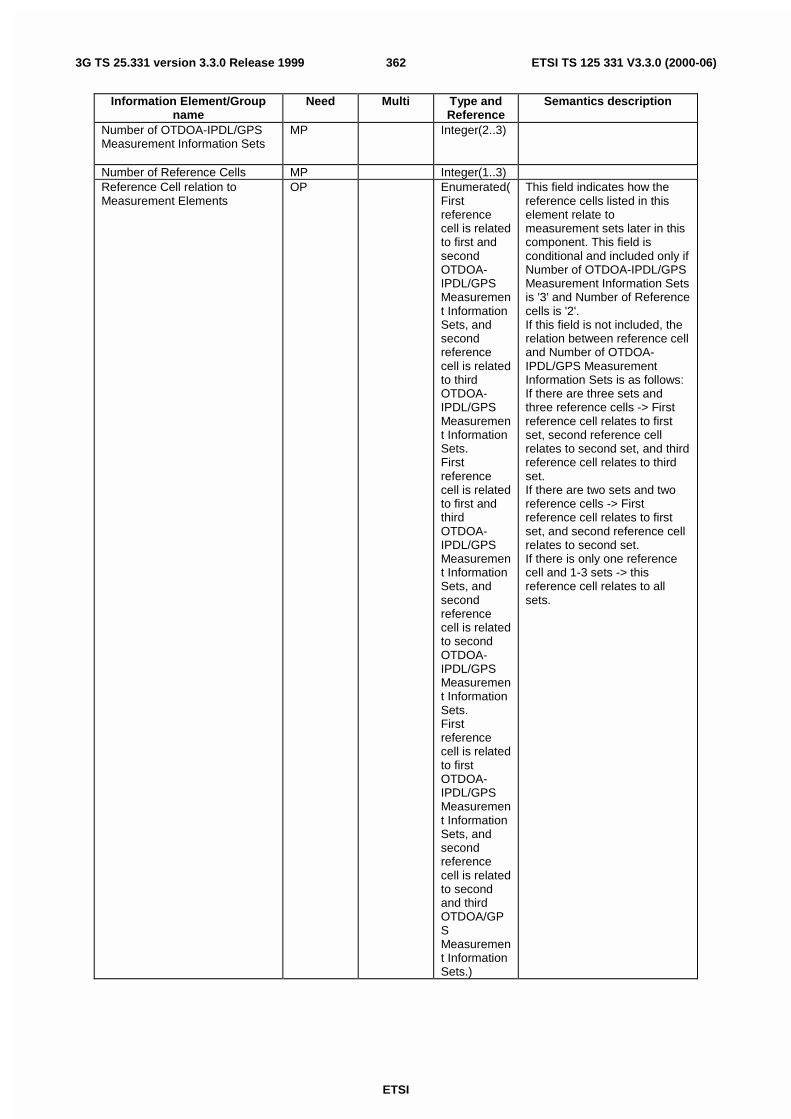
ETSI
ETSI TS 125 331 V3.3.0 (2000-06)3623G TS 25.331 version 3.3.0 Release 1999
Information Element/Groupname
Need Multi Type andReference
Semantics description
Number of OTDOA-IPDL/GPSMeasurement Information Sets
MP Integer(2..3)
Number of Reference Cells MP Integer(1..3)Reference Cell relation toMeasurement Elements
OP Enumerated(Firstreferencecell is relatedto first andsecondOTDOA-IPDL/GPSMeasurement InformationSets, andsecondreferencecell is relatedto thirdOTDOA-IPDL/GPSMeasurement InformationSets.Firstreferencecell is relatedto first andthirdOTDOA-IPDL/GPSMeasurement InformationSets, andsecondreferencecell is relatedto secondOTDOA-IPDL/GPSMeasurement InformationSets.Firstreferencecell is relatedto firstOTDOA-IPDL/GPSMeasurement InformationSets, andsecondreferencecell is relatedto secondand thirdOTDOA/GPSMeasurement InformationSets.)
This field indicates how thereference cells listed in thiselement relate tomeasurement sets later in thiscomponent. This field isconditional and included only ifNumber of OTDOA-IPDL/GPSMeasurement Information Setsis '3' and Number of Referencecells is '2'.If this field is not included, therelation between reference celland Number of OTDOA-IPDL/GPS MeasurementInformation Sets is as follows:If there are three sets andthree reference cells -> Firstreference cell relates to firstset, second reference cellrelates to second set, and thirdreference cell relates to thirdset.If there are two sets and tworeference cells -> Firstreference cell relates to firstset, and second reference cellrelates to second set.If there is only one referencecell and 1-3 sets -> thisreference cell relates to allsets.

ETSI
ETSI TS 125 331 V3.3.0 (2000-06)3633G TS 25.331 version 3.3.0 Release 1999
10.3.7.60 LCS OTDOA assistance data
Information Element/Groupname
Need Multi Type andReference
Semantics description
LCS OTDOA reference cell forassistance data
OP LCS OTDOAreferencecell forassistancedata10.3.7.64
LCS OTDOA measurementassistance data
OP 1 to<maxCellMeas>
LCS OTDOAmeasurement assistancedata10.3.7.63
LCS IPDL parameters OP LCS IPDLparameters10.3.7.55
If this element is not includedthere are no idle periodspresent

ETSI
ETSI TS 125 331 V3.3.0 (2000-06)3643G TS 25.331 version 3.3.0 Release 1999
10.3.7.61 LCS OTDOA assistance for SIB
Information Element/Groupname
Need Multi Type andReference
Semantics description
Ciphering parameters OP Determines if DGPS correctionfields are ciphered
>Ciphering Key Flag MP Bitstring(1) See note 1>Ciphering Serial Number MP Integer(0..65
535)The serial number used in theDES ciphering algorithm
Search Window Size MP Integer(10,20, 30, 40,50, 60,70,infinity)
Specifies the maximum size ofthe search window in chips.Infinity means more
Reference Cell Position MP Ellipsoidpoint orEllipsoidpoint withaltitude asdefined in23.032
The position of the antennawhich defines the serving cell.Used for the UE basedmethod.
LCS IPDL parameters OP LCS IPDLparameters10.3.7.55
If this element is not includedthere are no idle periodspresent
Cells to measure on MP 1 to<maxCellMeas>
>SFN-SFN drift OP Real(0,+0.33,+0.66,+1,+1.33,+1.66,+2,+2.5,+3,+4,+5,+7,+9,+11,+13,+15,-0.33,-0.66,-1,-1.33,-1.66,-2,-2.5,-3,-4,-5,-7,-9,-11,-13,-15)
The SFN-SFN drift valueindicate the relative time driftin meters per second. Positiveand negative values can beindicated as well as no driftvalue.
>Primary CPICH info MP PrimaryCPICH info10.3.6.51
>Frequency info OP Frequencyinfo10.3.6.30
Default the same. Included ifdifferent
>SFN-SFN observed timedifference
MP SFN-SFNobservedtimedifferencetype 1.10.3.7.88
Gives the relative timingcompared to the reference cell
>Fine SFN-SFN MP Real(0,0.25,0.5,0.75)
Gives finer resolution for UE-BasedIn chips
>Cell Position MD Default = Same as previouscell
>>Relative North MP Integer(-32767..32767)
Seconds, scale factor 0.03.Relative position compared toref. cell.
>>Relative East MP Integer(-32767..327676)
Seconds, scale factor 0.03.Relative position compared toref. cell.
>>Relative Altitude MP Integer(-4095..4095)
Relative altitude in meterscompared to ref. cell.

ETSI
ETSI TS 125 331 V3.3.0 (2000-06)3653G TS 25.331 version 3.3.0 Release 1999
NOTE 1: The UE always receives two (2) cipher keys during the location update procedure. One of the keys istime-stamped to be current one and the other is time-stamped to be the next one. Thus, the UE always hastwo cipher keys in memory. The Cipher Key Change Indicator in this broadcast message instructs the UEwhether to use current or next cipher key for deciphering the received broadcast message. The UE shallinterpret this IE as follows:
- Ciphering Key Flag(previous message) = Ciphering Key Flag(this message) => Deciphering Key not changed
- Ciphering Key Flag(previous message) <> Ciphering Key Flag(this message) => Deciphering Key changed
10.3.7.62 LCS OTDOA measurement
The purpose of the OTDOA Measurement Information element is to provide OTDOA measurements of signals sentfrom the reference and neighbor cells.

ETSI
ETSI TS 125 331 V3.3.0 (2000-06)3663G TS 25.331 version 3.3.0 Release 1999
Information Element/Groupname
Need Multi Type andReference
Semantics description
SFN MP Integer(0..4095)
SFN during which the lastmeasurement was performed
UE Rx-Tx time difference MP Real(876..1172 by step of0.25)
The UE Rx-Tx timing can beused to determine thepropagation delayIn chips
Quality type OP Enumerated(STD_10,STD_50,CPICHEc/N0)
Type of quality in the qualityfield,default=DEFAULT_QUALITY
CHOICE Quality type MP>STD_10>>Reference Quality 10 MP Integer(10..3
20 by step of10)
Std of TOA measurementsfrom the cell
>STD_50>>Reference Quality 50 MP Integer(50..1
600 by stepof 50)
Std of TOA measurementsfrom the cell
>CPICH Ec/N0>>CPICH Ec/N0 MP Enumerated(
<–24, -24 dB ≤ CPICHEc/No < –23dB,.. –1 dB ≤CPICHEc/No < –0dB, >=0 dB)
CPICH Ec/N0 for themeasurement
>DEFAULT_QUALITY>>Reference Quality MP Enumerated(
0-19 meters,20-39meters,40-79meters,80-159meters,160-319meters,320-639meters,640-1319metersover 1320meters)
Estimated error in meters.
Neighbors MP 0..maxCellMeas
Number of neighbors includedin this IE
>Neighbor Identity OP PrimaryCPICH info10.3.6.51
If this field is left out it theidentity is the same as in thefirst set of multiple sets.
>Neighbor Quality MP Bitstring(depends on Qualitytype)
Quality of the OTDOA from theneighbor cell.
>SFN-SFN observed timedifference
MP SFN-SFNobservedtimedifference10.3.7.88
Gives the timing relative to thereference cell. Only type 2 isallowed. Type 2 means thatonly the slot timing isaccounted for

ETSI
ETSI TS 125 331 V3.3.0 (2000-06)3673G TS 25.331 version 3.3.0 Release 1999
CHOICE Quality type Condition under which the given quality type ischosen
STD_10 Chosen when the quality type is standard deviationwith a step-size of 10 m
STD_50 Chosen when the quality type is standard deviationwith a step-size of 50 m
CPICH Ec/N0 Chosen when the quality type is CPICH Ec/N0Default Chosen if the quality type field is not included.
10.3.7.63 LCS OTDOA measurement assistance data
This IE gives approximate cell timing in order to decrease the search window.
Information Element/Groupname
Need Multi Type andReference
Semantics description
Primary CPICH info MP PrimaryCPICH info10.3.6.51
Frequency info OP Frequencyinfo10.3.6.30
Default the same. Included ifdifferent
SFN-SFN observed timedifference
MP SFN-SFNobservedtimedifferencetype 1.10.3.7.88
Gives the relative timingcompared to the reference cell
Fine SFN-SFN OP Real(0,0.25,0.5,0.75)
Gives finer resolution for UE-Based
Search Window Size MP Integer(10,20, 30, 40,50, 60,70,infinity)
Specifies the maximum size ofthe search window in chips.Infinity means more
Relative North OP Integer(-20000..20000)
Seconds, scale factor 0.03.Relative position compared toref. cell.
Relative East OP Integer(-20000..20000)
Seconds, scale factor 0.03.Relative position compared toref. cell.
Relative Altitude OP Integer(-4000..4000)
Relative altitude in meterscompared to ref. cell.
10.3.7.64 LCS OTDOA reference cell for assistance data
This IE defines the cell used for time references in all OTDOA measurements.
Information Element/Groupname
Need Multi Type andReference
Semantics description
Primary CPICH info MP PrimaryCPICH info10.3.6.51
Frequency info OP Frequencyinfo10.3.6.30
Default the same. Included ifdifferent
Cell Position OP Ellipsoidpoint orEllipsoidpoint withaltitude asdefined in23.032
The position of the antennawhich defines the cell. Can beused for the UE basedmethod.

ETSI
ETSI TS 125 331 V3.3.0 (2000-06)3683G TS 25.331 version 3.3.0 Release 1999
10.3.7.65 LCS position
The purpose of Location Information element is to provide the location estimate from the UE to the network, if the UEis capable of determining its own position.
Information Element/Groupname
Need Multi Type andReference
Semantics description
Reference SFN MP Integer(0..4095)
The SFN for which the locationis valid
GPS TOW msec CV-Capabilityandrequest
Integer(0..6.
048*108-1)
GPS Time of Week Week inmilliseconds (rounded down tothe nearest millisecond unit).This time-stamps thebeginning of the frame definedin Reference SFNGPS Time of Week inmicroseconds = 1000 * GPSTOW msec + GPS TOW remusec
GPS TOW rem usec CV-Capabilityandrequest
Integer(0..999)
GPS Time of Week inmicroseconds MOD 1000.
Position estimate MP 23.032,allowedtypes areEllipsoidPoint;Ellipsoidpoint withuncertaintycircle;Ellipsoidpoint withuncertaintyellipse;Ellipsoidpoint withaltitude;Ellipsoidpoint withaltitude anduncertaintyellipse.
Condition ExplanationCapability and request This field is included only if the UE has this capability
and if it was requested in the LCS reporting quantityand if the method was UE-based GPS

ETSI
ETSI TS 125 331 V3.3.0 (2000-06)3693G TS 25.331 version 3.3.0 Release 1999
10.3.7.66 LCS reporting criteria
The triggering of the event-triggered reporting for an LCS measurement. There are three types of events. The first, 7a, isfor UE-based methods and is triggered when the position has changed more than a threshold. The second one, 7b, isprimarily for UE assisted methods, but can be used also for UE based. It is triggered when the SFN-SFN measurementhas changed more than a certain threshold. The third one, 7c, is triggered when the GPS time and the SFN time hasdrifted apart more than a certain threshold.
Information Element/Groupname
Need Multi Type andReference
Semantics description
Parameters required for eachevent
OP 1 to<maxMeasEvent>
>Event ID MP Enumerated(7a,7b,7c)
7a=Position change7b=SFN-SFN change,7c=SFN-GPS TOW change
>Amount of reporting MP Integer(1, 2,4, 8, 16, 32,64,infinite)
>Report first fix MP Boolean If true the UE reports theposition once themeasurement control isreceived, and then each timean event is triggered.
>Measurement interval MP Integer(5,15,60,300,900,1800,3600,7200)
Indicates how often the UEshould make the measurementIn seconds
>CHOICE Event ID>>7a>>>Threshold Position Change MP Integer(10,2
0,30,40,50,100,200,300,500,1000,2000,5000,10000,20000,50000,100000)
Indicated how much theposition should changecompared to last reportedposition fix in order to triggerthe event.
>>7b>>>Threshold SFN-SFN change MP Real(0.25,0.
5,1,2,3,4,5,10,20,50,100,200,500,1000,2000,5000)
Chips. Indicates how much theSFN-SFN measurement ofANY measured cell is allowedto change before the event istriggered.
>>7c>>>Threshold SFN-GPS TOW MP Integer(1,2,3
,5,10,20,50,100)
Time in ms. When the GPSTOW and SFN timer hasdrifted apart more than thespecified value the event istriggered)
10.3.7.67 LCS reporting quantity
The purpose of the element is to express the allowed/required location method(s), and to provide information requiredQoS.

ETSI
ETSI TS 125 331 V3.3.0 (2000-06)3703G TS 25.331 version 3.3.0 Release 1999
Information Element/Groupname
Need Multi Type andReference
Semantics description
Method Type MP Enumerated(UE assisted,UE based,UE based ispreferred butUE assistedis allowed,UE assistedis preferredbut UEbased isallowed)
Positioning Methods MP Enumerated(OTDOA,GPSOTDOA orGPS)
Indicates which locationmethod or methods should beused. The third option meansthat both can be reported.OTDOA includes IPDL if idleperiods are present.
Response Time MP Integer(1,2,4, 8, 16, 32,64, 128)
Indicates the desired responsetime in seconds
Accuracy CV Bit string(7) Mandatory in all cases exceptwhen Method Type is UEassisted, then it is optional.23.032
GPS timing of Cell wanted MP Boolean If true the SRNC wants the UEto report the SFN-GPS timingof the reference cell. This ishowever optional in the UE.
Multiple Sets MP Boolean This field indicates whether UEis requested to send multipleOTDOA/GPS MeasurementInformation Sets. Themaximum number ofmeasurement sets is three.This is field is mandatory. UEis expected to include thecurrent measurement set.
Environment Characterisation OP Enumerated(possiblyheavymultipathand NLOSconditions,no or lightmultipathand usuallyLOSconditions,not definedor mixedenvironment)
The first category correspondto e.g. Urban or Bad Urbanchannels.
The second categorycorresponds to Rural orSuburban channels

ETSI
ETSI TS 125 331 V3.3.0 (2000-06)3713G TS 25.331 version 3.3.0 Release 1999
10.3.7.68 Maximum number of reported cells on RACH
Information Element/Groupname
Need Multi Type andreference
Semantics description
Maximum number of reportedcells
MP Enumerated(no report,current cell,current cell +bestneighbour,currentcell+2 bestneighbours,…, currentcell+6 bestneighbours)
10.3.7.69 Measured results
Contains the measured results of the quantity indicated optionally by Reporting Quantity in Measurement Control."Measured results" can be used for both event trigger mode and periodical reporting mode. The list should be in theorder of the value of the measurement quality (the first cell should be the best cell). The "best" FDD cell has the largestvalue when the measurement quantity is "Ec/No" or "RSCP". On the other hand, the "best" cell has the smallest valuewhen the measurement quantity is "Pathloss". The "best" TDD cell has the largest value when measurement quantity is"Primary CCPCH RSCP".
Information Element/Groupname
Need Multi Type andreference
Semantics description
CHOICE Measurement MP>Intra-frequency measuredresults list
Intra-frequencymeasuredresults list10.3.7.35
>Inter-frequency measuredresults list
Inter-frequencymeasuredresults list10.3.7.15
>Inter-system measured resultslist
Inter-systemmeasuredresults list10.3.7.26
>Traffic volume measuredresults list
Trafficvolumemeasuredresults list10.3.7.92
>Quality measured results list Qualitymeasuredresults list10.3.7.80
>UE Internal measured results UE Internalmeasuredresults10.3.7.101
>LCS measured results LCSmeasuredresults10.3.7.56

ETSI
ETSI TS 125 331 V3.3.0 (2000-06)3723G TS 25.331 version 3.3.0 Release 1999
10.3.7.70 Measured results on RACH
Contains the measured results on RACH of the quantity indicated optionally by Reporting Quantity in the systeminformation broadcast on BCH. The list should be in the order of the value of the measurement quality (the first cellshould be the best cell). The "best" FDD cell has the largest value when the measurement quantity is "Ec/No" or"RSCP". On the other hand, the "best" cell has the smallest value when the measurement quantity is "Pathloss". The"best" TDD cell has the largest value when measurement quantity is "Primary CCPCH RSCP".
Information Element/groupname
Need Multi Type andreference
Semantics description
Measurement result for currentcellCHOICE mode MP>FDD>>CHOICE measurementquantity
MP
>>>CPICH Ec/N0 Integer(-20..0)
In dB
>>>CPICH RSCP Integer(-115..-40)
In dBm
>>>Pathloss Integer(46..158)
In dB
>TDD>>Timeslot List OP 1 to 14>>>Timeslot ISCP MP Timeslot
ISCP info10.3.7.90
The UE shall report theTimeslot ISCP in the sameorder as indicated in the cellinfo
>>Primary CCPCH RSCP OP PrimaryCCPCHRSCP info10.3.7.79
Measurement results formonitored cells
OP 1 to 7
>SFN-SFN observed timedifference
OP SFN-SFNobservedtimedifference10.3.7.88
It is absent for current cell
>CHOICE mode MP>>FDD>>>Primary CPICH info MP Primary
CPICH info10.3.6.51
>>>CHOICE measurementquantity
OP It is absent for current cell
>>>>CPICH Ec/N0 Integer(-20..0)
In dB
>>>>CPICH RSCP Integer(-115..-40)
In dBm
>>>>Pathloss Integer(46..158)
In dB
>>TDD>>>Primary CCPCH info MP Primary
CCPCH info10.3.6.49
>>>Primary CCPCH RSCP OP PrimaryCCPCHRSCP info10.3.7.79
It is absent for current cell
NOTE 1: Monitored cells consist of current cell and neighbouring cells.

ETSI
ETSI TS 125 331 V3.3.0 (2000-06)3733G TS 25.331 version 3.3.0 Release 1999
10.3.7.71 Measurement Command
Information Element/Groupname
Need Multi Type andreference
Semantics description
Measurement command MP Enumerated(Setup,Modify,Release)
10.3.7.72 Measurement control system information
Information element/Groupname
Need Multi Type andreference
Semantics description
Intra-frequency measurementsystem information
OP Intra-frequencymeasurement systeminformation10.3.7.40
Inter-frequency measurementsystem information
OP Inter-frequencymeasurement systeminformation10.3.7.20
Inter-system measurementsystem information
OP Inter-systemmeasurement systeminformation10.3.7.31
Traffic volume measurementsystem information
OP Trafficvolumemeasurement systeminformation10.3.7.98
UE Internal measurementsystem information
OP UE Internalmeasurement systeminformation10.3.7.106
NOTE1: The reporting of intra-frequency measurements is activated when state CELL_DCH is entered.
10.3.7.73 Measurement Identity Number
A reference number that is used by the UTRAN at modification and release of the measurement, and by the UE in themeasurement report.
Information Element/Groupname
Need Multi Type andreference
Semanticsdescription
Measurement identity number MP Integer(1..16)
10.3.7.74 Measurement reporting mode
Contains the type of Measurement Report transfer mode and the indication of periodical/event trigger.

ETSI
ETSI TS 125 331 V3.3.0 (2000-06)3743G TS 25.331 version 3.3.0 Release 1999
Information Element/Groupname
Need Multi Type andreference
Semanticsdescription
Measurement Report TransferMode
MP enumerated(Acknowledgedmode RLC,Unacknowledgedmode RLC)
Periodical Reporting / EventTrigger Reporting Mode
MP Enumerated(Periodicalreporting, Eventtrigger)
10.3.7.75 Measurement Type
Information Element/Groupname
Need Multi Type andreference
Semanticsdescription
Measurement Type MP Enumerated(Intra-frequency,Inter-frequency,Inter-system,Traffic volume,Quality,UE internal, LCS)
10.3.7.76 Measurement validity
Information Element/Groupname
Need Multi Type andreference
Semantics description
Resume/release MP Enumerated('resume','release')
Indicates whether a givenmeasurement identifier shouldbe released after transitions toCELL_DCH and/or transitionsfrom CELL_DCH state.
UE state CV –Resume
Enumerated(CELL_DCH,all statesexceptCELL_DCH,all states)
Indicates the states, in whichmeasurement reporting shallbe conducted.The values 'all states exceptCELL_DCH' and 'all states' areused for measurement type'traffic volume reporting'.
Condition ExplanationResume This IE is mandatory if "Resume/Release" = Resume,
otherwise the IE is not needed
10.3.7.77 Observed time difference to GSM cell
Information Element/Groupname
Need Multi Type andreference
Semantics description
Observed time difference toGSM cell
OP Real(0.0..4095*3060/(4096*13 bystep of3060/(4096*13))
In ms
10.3.7.78 Periodical reporting criteria
Contains the periodical reporting criteria information. It is necessary only in the periodical reporting mode.

ETSI
ETSI TS 125 331 V3.3.0 (2000-06)3753G TS 25.331 version 3.3.0 Release 1999
Information Element/Groupname
Need Multi Type andreference
Semantics description
Amount of reporting MD Integer(1, 2,4, 8, 16, 32,64, Infinity)
Measurement is "released"after the indicated amount ofreporting from the UE itself.The default value is infinity.
Reporting interval MP Integer(250,500, 1000,2000, 3000,4000, 6000,8000, 12000,16000,20000,24000,28000,32000,64000)
Indicates the interval ofperiodical report.Interval in miliseconds
10.3.7.79 Primary CCPCH RSCP info
NOTE: Only for TDD
Information Element/Groupname
Need Multi IE type andreference
Semantics description
Primary CCPCH RSCP MP Enumerated(-115, -114... –25)
Granularity 1dB
10.3.7.80 Quality measured results list
Information Element/Groupname
Need Multi Type andreference
Semantics description
BLER measurement results OP 1 to<maxTrCH>
>DL Transport channel identity MP Transportchannelidentity10.3.5.18
>DL Transport Channel BLER OP Real(0.00..1.00, by step of 0.02)
In dB=-Log10(Transport channelBLER)
CHOICE mode>FDD>>SIR OP Integer(-
10..20)In dB
>TDD>>SIR measurement results OP 1 to
<MaxCCTrCH>
SIR measurements for DLCCTrCH
>>>TFCS ID MP Enumerated(1...8)
>>>Timeslot list MP 1 to<maxTS>
for all timeslot on which theCCTrCH is mapped on
>>>>SIR MP Integer(-10...20)
the UE shall report inascending timeslot order

ETSI
ETSI TS 125 331 V3.3.0 (2000-06)3763G TS 25.331 version 3.3.0 Release 1999
10.3.7.81 Quality measurement
Information Element/Groupname
Need Multi Type andreference
Semantics description
Quality reporting quantity OP Qualityreportingquantity10.3.7.84
CHOICE report criteria MP>Quality measurement reporting criteria
Qualitymeasurement reportingcriteria10.3.7.83
>Periodical reporting criteria Periodicalreportingcriteria10.3.7.78
>No reporting (no data)Chosen when thismeasurement only is used asadditional measurement toanother measurement
10.3.7.82 Quality measurement event results (FFS)
Information Element/Groupname
Need Multi Type andreference
Semantics description
Transport channels causing theevent
OP 1 to<maxTrCH>
>Transport channel identity MP Transportchannelidentity10.3.5.18
10.3.7.83 Quality measurement reporting criteria
Event 5a: Number of bad CRCs on a certain transport channel exceeds a threshold.
Information Element/Groupname
Need Multi Type andreference
Semantics description
Parameters sent for eachtransport channel
OP 1 to<maxTrCH>
>Tranpsport channel identity MP Tranpsortchannelidentity10.3.5.18
>Total CRC MP Integer(1..512)
Number of CRCs
>Bad CRC MP Integer(1..512)
Number of CRCs
>Pending after trigger MP Integer(1..512)
Number of CRCs

ETSI
ETSI TS 125 331 V3.3.0 (2000-06)3773G TS 25.331 version 3.3.0 Release 1999
10.3.7.84 Quality reporting quantity
Information Element/Groupname
Need Multi Type andreference
Semantics description
DL Transport Channel BLER MP Boolean TRUE means report requestedTransport channels for BLERreporting
CV BLERreporting
1 to<maxTrCH>
The default, if no transportchannel identities are present,is that the BLER is reported forall downlink transport channels
>DL Transport channel identity MP Transportchannelidentity10.3.5.18
CHOICE mode>FDD>>SIR MP Boolean TRUE means report requested>TDD>>SIR measurement list OP 1 to
<maxCCTrCH>
SIR measurements shall bereported for all listed TFCS IDs
>>>TFCS ID MP Enumerated(1...8)
Condition ExplanationBLER reporting This information element is absent if 'DL Transport
Channel BLER' is 'False' and optional, if 'DL TransportChannel BLER' is 'True'
10.3.7.85 Reference time difference to cell
In the System Information message, the reference time difference to cell indicates the SFN-SFN time differencebetween the primary CCPCH of the current cell and the primary CCPCH of a neighbouring cell..
In the Measurement Control message, the the reference time difference to cell indicates the CFN-SFN time differencebetween UE uplink transmission timing and the primary CCPCH of a neighbouring cell.
Information Element/Groupname
Need Multi Type andreference
Semantics description
CHOICE accuracy MP>40 chips>>Reference time difference MP Integer(0..384
00 by step of40)
In chips
>256 chips>>Reference time difference MP Integer(0..
38400 by stepof 256)
In chips
>2560 chips>>Reference time difference MP Integer(0..
38400 by stepof 2560)
In chips
10.3.7.86 Reporting Cell Status
Indicates maximum allowed number of cells to report and whether active set cells and/or virtual active set cells and/ormonitored set cells on used frequency and/or monitored set cells on non used frequency should/should not be includedin the IE "Measured results".

ETSI
ETSI TS 125 331 V3.3.0 (2000-06)3783G TS 25.331 version 3.3.0 Release 1999
Information Element/Groupname
Need Multi Type andreference
Semanticsdescription
Choice reporting cell MP>Within active set cells>> Maximum number ofreporting cells type1
MP Integer(1..6)
>Within monitored set cells onused frequency>> Maximum number ofreporting cells type1
MP Integer(1..6)
>Within monitored cells on usedfrequency>> Maximum number ofreporting cells type1
MP Integer(1..6)
>Include all active set cells +within monitored set cells onused frequency>> Maximum number ofreporting cells type3
MP Enumerated(virtual/active setcells+1,virtual/active setcells+2, ….,virtual/active setcells+6)
>Within virtual active set cells>> Maximum number ofreporting cells type1
MP Integer(1..6)
>Within monitored set cells onnon-used frequency>> Maximum number ofreporting cells type1
MP Integer(1..6)
>Within monitored cells on non-used frequency>> Maximum number ofreporting cells type1
MP Integer(1..6)
>Include all virtual active setcells + within monitored set cellson non-used frequency>> Maximum number ofreporting cells type3
MP Enumerated(virtual/active setcells+1,virtual/active setcells+2, ….,virtual/active setcells+6)
>Within active set cells or withinvirtual active set cells>> Maximum number ofreporting cells type2
MP Integer (1..12)
>Within monitored cells on usedfrequency or within monitoredcells on non-used frequency>> Maximum number ofreporting cells type2
MP Integer(1..12)

ETSI
ETSI TS 125 331 V3.3.0 (2000-06)3793G TS 25.331 version 3.3.0 Release 1999
10.3.7.87 Reporting information for state CELL_DCH
Information Element/Groupname
Need Multi Type andreference
Semanticsdescription
Intra-frequency reportingquantity
MP Intra-frequencyreporting quantity10.3.7.41
Measurement Reporting Mode MP MeasurementReporting Mode10.3.7.74
CHOICE report criteria MP>Intra-frequency measurementreporting criteria
Intra-frequencymeasurementreporting criteria10.3.7.39
>Periodical reporting criteria Periodical reportingcriteria 10.3.7.78
10.3.7.88 SFN-SFN observed time difference
Information Element/Groupname
Need Multi Type andreference
Semanticsdescription
CHOICE type MP>Type 1 Integer(0..9830399) Number of chips>Type 2 Real(-
1279.75..1280.0 bystep of 0.25)
Number of chips
10.3.7.89 Time to trigger
Information Element/Groupname
Need Multi Type andreference
Semantics description
Time to trigger MP Integer(0,10, 20, 40,60, 80, 100,120, 160,200, 240,320, 640,1280, 2560,5000)
Indicates the period of timebetween the timing of eventdetection and the timing ofsending Measurement Report.Time in ms
10.3.7.90 Timeslot ISCP info
NOTE: Only for TDD
Information Element/Groupname
Need Multi IE type andreference
Semantics description
Timeslot ISCP MP Integer (-115... –25)
In dB
10.3.7.91 Traffic volume event identity
Information Element/Groupname
Need Multi Type andreference
Semantics description
Traffic volume event identity MP Enumerated(4a, 4b)

ETSI
ETSI TS 125 331 V3.3.0 (2000-06)3803G TS 25.331 version 3.3.0 Release 1999
10.3.7.92 Traffic volume measured results list
Information Element/Groupname
Need Multi Type andreference
Semantics description
Traffic volume measurementresults
OP 1 to<maxRB>
>RB Identity MP RB Identity10.3.4.13
>RLC buffers payload OP Enumerated(0, 4, 8, 16,32, 64, 128,256, 512,1024, 2K,4K, 8K, 16K,32K, 64K,128K, 256K,512K,1024K)
In bytesAnd N Kbytes = N*1024 bytes
>Average RLC buffer payload OP Enumerated(0, 4, 8, 16,32, 64, 128,256, 512,1024, 2K,4K, 8K, 16K,32K, 64K,128K, 256K,512K,1024K)
In bytesAnd N Kbytes = N*1024 bytes
>Variance of RLC buffer payload OP Enumerated(0, 4, 8, 16,32, 64, 128,256, 512,1024, 2K,4K, 8K, 16K)
In bytesAnd N Kbytes = N*1024 bytes

ETSI
ETSI TS 125 331 V3.3.0 (2000-06)3813G TS 25.331 version 3.3.0 Release 1999
10.3.7.93 Traffic volume measurement
Information Element/Groupname
Need Multi Type andreference
Semantics description
Traffic volume measurement Object
OP Trafficvolumemeasurement Object10.3.7.95
Traffic volume measurement quantity
OP Trafficvolumemeasurement quantity10.3.7.96
Traffic volume reporting quantity OP Trafficvolumereportingquantity10.3.7.99
Measurement validity OP Measurement validity10.3.7.76
CHOICE report criteria MP>Traffic volume measurement reporting criteria
Trafficvolumemeasurement reportingcriteria10.3.7.97
>Periodical reporting criteria Periodicalreportingcriteria10.3.7.78
>No reporting (no data)Chosen when thismeasurement only is used asadditional measurement toanother measurement
10.3.7.94 Traffic volume measurement event results
Contains the event result for a traffic volume measurement.
Information Element/Groupname
Need Multi Type andreference
Semantics description
UL Transport Channel causingthe event
MP Transportchannelidentity10.3.5.18
Traffic volume event identity MP Trafficvolumeeventidentity10.3.7.91

ETSI
ETSI TS 125 331 V3.3.0 (2000-06)3823G TS 25.331 version 3.3.0 Release 1999
10.3.7.95 Traffic volume measurement object
Contains the measurement object information for a traffic volume measurement.
Information Element/Groupname
Need Multi Type andreference
Semantics description
Traffic volume measurementobjects
MP 1 to<maxTrCH>
>UL Target Transport ChannelID
MP Transportchannelidentity10.3.5.18
10.3.7.96 Traffic volume measurement quantity
Contains the measurement quantity information for a traffic volume measurement.
Information Element/Groupname
Need Multi Type andreference
Semantics description
Measurement quantity MP Enumerated(RLC bufferpayload,AverageRLC bufferpayload,Variance ofRLC bufferpayload)
Time Interval to take an averageor a vaiance
CV-A/V Integer(20,40, ..260, bysteps of 20)
In msAt least 3 spare values,Criticality: reject, are needed.
Condition ExplanationA/V This IE is present when "Average RLC buffer" or
"Variance of RLC buffer payload" is chosen.
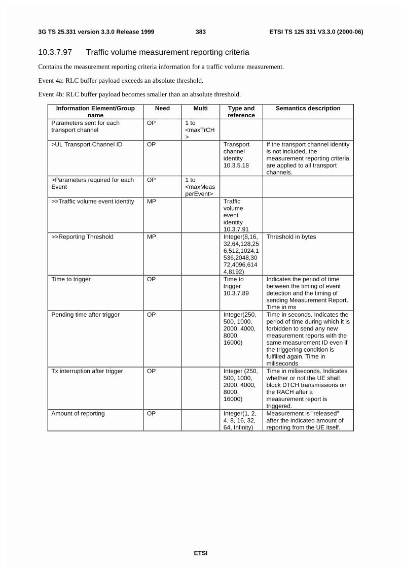
ETSI
ETSI TS 125 331 V3.3.0 (2000-06)3833G TS 25.331 version 3.3.0 Release 1999
10.3.7.97 Traffic volume measurement reporting criteria
Contains the measurement reporting criteria information for a traffic volume measurement.
Event 4a: RLC buffer payload exceeds an absolute threshold.
Event 4b: RLC buffer payload becomes smaller than an absolute threshold.
Information Element/Groupname
Need Multi Type andreference
Semantics description
Parameters sent for eachtransport channel
OP 1 to<maxTrCH>
>UL Transport Channel ID OP Transportchannelidentity10.3.5.18
If the transport channel identityis not included, themeasurement reporting criteriaare applied to all transportchannels.
>Parameters required for eachEvent
OP 1 to<maxMeasperEvent>
>>Traffic volume event identity MP Trafficvolumeeventidentity10.3.7.91
>>Reporting Threshold MP Integer(8,16,32,64,128,256,512,1024,1536,2048,3072,4096,6144,8192)
Threshold in bytes
Time to trigger OP Time totrigger10.3.7.89
Indicates the period of timebetween the timing of eventdetection and the timing ofsending Measurement Report.Time in ms
Pending time after trigger OP Integer(250,500, 1000,2000, 4000,8000,16000)
Time in seconds. Indicates theperiod of time during which it isforbidden to send any newmeasurement reports with thesame measurement ID even ifthe triggering condition isfulfilled again. Time inmiliseconds
Tx interruption after trigger OP Integer (250,500, 1000,2000, 4000,8000,16000)
Time in miliseconds. Indicateswhether or not the UE shallblock DTCH transmissions onthe RACH after ameasurement report istriggered.
Amount of reporting OP Integer(1, 2,4, 8, 16, 32,64, Infinity)
Measurement is "released"after the indicated amount ofreporting from the UE itself.

ETSI
ETSI TS 125 331 V3.3.0 (2000-06)3843G TS 25.331 version 3.3.0 Release 1999
10.3.7.98 Traffic volume measurement system information
Information Element/Groupname
Need Multi Type andreference
Semantics description
Traffic volume measurementidentity number
MD Measurement identitynumber10.3.7.73
The traffic volumemeasurement identity numberhas default value 4.
Traffic volumemeasurement objects
OP Trafficvolumemeasurement objects10.3.7.95
Traffic volumemeasurement quantity
OP Trafficvolumemeasurement quantity10.3.7.96
Traffic volume reporting quantity OP Trafficvolumereportingquantity10.3.7.99
Measurement validity OP Measurement validity10.3.7.76
Measurement Reporting Mode MP Measurement ReportingMode10.3.7.74
CHOICE reporting criteria MP>Traffic volume measurementreporting criteria
Trafficvolumemeasurement reportingcriteria10.3.7.97
>Periodical reporting criteria Periodicalreportingcriteria10.3.7.78
10.3.7.99 Traffic volume reporting quantity
Contains the reporting quantity information for a traffic volume measurement.
For all boolean types TRUE means inclusion in the report is requested.
Information Element/Groupname
Need Multi Type andreference
Semantics description
RLC buffer payload for each RB MP BooleanAverage RLC buffer payload foreach RB
MP Boolean
Variance of RLC buffer payloadfor each RB
MP Boolean

ETSI
ETSI TS 125 331 V3.3.0 (2000-06)3853G TS 25.331 version 3.3.0 Release 1999
10.3.7.100 UE internal event identity
Information Element/Groupname
Need Multi Type andreference
Semantics description
UE internal event identity MP Enumerated(6a,6b,6c,6d,6e, 6f, 6g)
10.3.7.101 UE internal measured results
Information Element/Groupname
Need Multi Type andreference
Semantics description
CHOICE mode MP>FDD>>UE Transmitted Power OP Integer(-
50..33)UE transmitted power In dBm
>>UE Rx-Tx report entries OP 1 to<maxRL>
>>>Primary CPICH info MP PrimaryCPICH info10.3.6.51
Primary CPICH info for eachcell included in the active set
>>>UE Rx-Tx time difference MP UE Rx-Txtimedifference10.3.7.108
UE Rx-Tx time difference inchip for each RL included inthe active set
>TDD>>UE transmitted Power list OP 1 to
<maxTS>
UE transmitted power for eachused uplink timeslot inascending timeslot numberorder
>>>UE transmitted power MP UEtransmittedpower info10.3.7.109
>>Applied TA OP UplinkTimingAdvance10.3.6.82

ETSI
ETSI TS 125 331 V3.3.0 (2000-06)3863G TS 25.331 version 3.3.0 Release 1999
10.3.7.102 UE internal measurement
Information Element/Groupname
Need Multi Type andreference
Semantics description
UE internal measurement quantity
OP UE internalmeasurement quantity10.3.7.104
UE internal reporting quantity OP UE internalreportingquantity10.3.7.107
CHOICE report criteria MP>UE internal measurement reporting criteria
UE internalmeasurement reportingcriteria10.3.7.105
>Periodical reporting criteria Periodicalreportingcriteria10.3.7.78
>No reporting (no data)Chosen when thismeasurement only is used asadditional measurement toanother measurement
CHOICE report criteria Condition under which the given report criteria ischosen
UE internal measurement reporting criteria Chosen when UE internal measurement eventtriggering is required
Periodical reporting criteria Chosen when periodical reporting is requiredNo reporting Chosen when this measurement only is used as
additional measurement to another measurement
10.3.7.103 UE internal measurement event results
This IE contains the measurement event results that are reported to UTRAN for UE internal measurements.
Information Element/Groupname
Need Multi Type andreference
Semantics description
UE internal event identity MP UE internaleventidentity10.3.7.100
CHOICE mode MP>FDD>Primary CPICH info CV -
clause 1PrimaryCPICH info10.3.6.51
>TDD (no data)
Condition ExplanationClause 1 This IE is mandatory if "UE internal event identity" is
set to "6f" or "6g", otherwise the IE is not needed
10.3.7.104 UE internal measurement quantity
The quantity the UE shall measure in case of UE internal measurement.

ETSI
ETSI TS 125 331 V3.3.0 (2000-06)3873G TS 25.331 version 3.3.0 Release 1999
Information Element/Groupname
Need Multi Type andreference
Semantics description
CHOICE mode MP>FDD>>Measurement quantity MP Enumerated(
UETransmittedPower,UTRACarrierRSSI, UERx-Tx timedifference)
>TDD>>Measurement quantity MP Enumerated(
UETransmittedPower,UTRACarrierRSSI)
Filter coefficient MP Filtercoefficient10.3.7.9
10.3.7.105 UE internal measurement reporting criteria
The triggering of the event-triggered reporting for a UE internal measurement. All events concerning UE internalmeasurements are labelled 6x where x is a, b, c…. In TDD, the events 6a - 6d are measured and reported on timeslotbasis.
Event 6a: The UE Transmitted Power becomes larger than an absolute threshold
Event 6b: The UE Transmitted Power becomes less than an absolute threshold
Event 6c: The UE Transmitted Power reaches its minimum value
Event 6d: The UE Transmitted Power reaches its maximum value
Event 6e: The UE RSSI reaches the UEs dynamic receiver range
Event 6f: The UE Rx-Tx time difference for a RL included in the active set becomes larger than an absolute threshold
Event 6g: The UE Rx-Tx time difference for a RL included in the active set becomes less than an absolute threshold

ETSI
ETSI TS 125 331 V3.3.0 (2000-06)3883G TS 25.331 version 3.3.0 Release 1999
Information Element/Groupname
Need Multi Type andreference
Semantics description
Parameters sent for each UEinternal measurement event
OP 1 to<maxMeasEvent>
> UE internal event identity MP UE internaleventidentity10.3.7.100
>Time-to-trigger MP Integer(0,10, 20, 40,60, 80, 100,120, 160,200, 240,320, 640,1280, 2560,5000)
Time in ms. Indicates theperiod of time between thetiming of event detection andthe timing of sendingMeasurement Report.
>UE Transmitted power Txpower threshold
CV -clause 1
Integer(-50..33)
Power in dBm. In event 6a, 6b.
>UE Rx-Tx time differencethreshold
CV -clause 2
Integer(769..1280)
Time difference in chip. Inevent 6f, 6g.
Condition ExplanationClause 1 The IE is mandatory if UE internal event identity" is
set to "6a" or "6b", otherwise the IE is not neededClause 2 The IE is mandatory if "UE internal event identity" is
set to "6f" or "6g", otherwise the IE is not needed
10.3.7.106 UE internal measurement system information
Information Element/Groupname
Need Multi Type andreference
Semantics description
UE internal measurement identitynumber
MD Measurement identitynumber10.3.7.73
The UE internal measurementidentity number has defaultvalue 5.
UE internal measurement quantity
MP UE internalmeasurement quantity10.3.7.104
10.3.7.107 UE Internal reporting quantity
For all boolean types TRUE means inclusion in the report is requested.
Information Element/Groupname
Need Multi Type andreference
Semantics description
UE Transmitted Power MP BooleanCHOICE mode MP>FDD>>UE Rx-Tx time difference MP Boolean>TDD>>Applied TA MP Boolean
10.3.7.108 UE Rx-Tx time difference
The difference in time between the UE uplink DPCCH/DPDCH frame transmission and the first significant path, of thedownlink DPCH frame from the measured radio link. This measurement is for FDD only.

ETSI
ETSI TS 125 331 V3.3.0 (2000-06)3893G TS 25.331 version 3.3.0 Release 1999
Information Element/Groupname
Need Multi Type andreference
Semanticsdescription
UE Rx-Tx time difference MP Integer(876..1172)
In chips.
10.3.7.109 UE Transmitted Power info
Information Element/Groupname
Need Multi IE type andreference
Semantics description
UE Transmitted Power MP Integer (-50... 33)
In dB
10.3.8 Other Information elements
10.3.8.1 BCCH modification info
Indicates modification of the System Information on BCCH.
Information Element/Groupname
Need Multi Type andreference
Semantics description
MIB Value tag MP MIB Valuetag 10.3.8.7
BCCH Modification time OP Integer (0..8,16, 24, ..4088)
All SFN values in which MIBmay be mapped are allowed.
10.3.8.2 BSIC
Information Element/Groupname
Need Multi Type andreference
Semantics description
Base transceiver Station IdentityCode (BSIC)
MP [TS 23.003]
>Network Colour Code (NCC) MP bit string(3)>Base Station Colour Code(BCC)
MP bit string(3)
10.3.8.3 CBS DRX Level 1 information
This information element contains the CBS discontinuous reception information to be broadcast for CBS DRX Level 1calculations in the UE.
Information Element/Groupname
Need Multi Type andreference
Semantics description
Period of CTCH allocation (N) MP Integer(1..256)
MTTI ≤ N ≤ 4096 – K,N multiple of MTTI
CBS frame offset (K) MP Integer(0..255)
0 ≤ K ≤ N-1,K multiple of MTTI
10.3.8.4 Cell Value tag
Information Element/Groupname
Need Multi Type andreference
Semantics description
Cell Value tag MP Integer (1..4)

ETSI
ETSI TS 125 331 V3.3.0 (2000-06)3903G TS 25.331 version 3.3.0 Release 1999
10.3.8.5 Inter-System handover failure
Information Element/Groupname
Need Multi Type andreference
Semantics description
Inter-System handover failurecause
MD Enumerated(Configurationunacceptable,physicalchannel failure,protocol error,unspecified)
Default value is "unspecified".
At least 3 spare values,criticality = default, arerequired
Protocol error information CV-ProtErr Protocol errorinformation10.3.8.10
Inter-System message OP Inter-Systemmessage10.3.8.6
Condition ExplanationProtErr If the IE "Inter-system handover failure cause" has the
value "Protocol error"
10.3.8.6 Inter-system message
This Information Element contains one or several messages that are structured and coded according to the specificationused for the system type indicated by the first parameter.
Information Element/Groupname
Need Multi Type andreference
Semantics description
System type MP Enumerated(GSM,cdma2000)
At least 14 spare values,Criticality: reject, are needed
CHOICE system MP At least 14 spare choices,Criticality: reject, are needed
>GSM>>Message(s) MP 1.to.<maxI
nterSysMessages>
Bitstring(1..512)
Formatted and codedaccording to GSMspecifications
>cdma2000>>cdma2000Message MP 1.to.<maxI
nterSysMessages>
>>>MSG_TYPE(s) MP Bitstring (8) Formatted and codedaccording to cdma2000specifications
>>>cdma2000Messagepayload(s)
MP Bitstring(1..512)
Formatted and codedaccording to cdma2000specifications
10.3.8.7 MIB Value tag
Information Element/Groupname
Need Multi Type andreference
Semantics description
MIB Value tag MP Integer (1..8)

ETSI
ETSI TS 125 331 V3.3.0 (2000-06)3913G TS 25.331 version 3.3.0 Release 1999
10.3.8.8 PLMN Value tag
Information Element/Groupname
Need Multi Type andreference
Semantics description
PLMN Value tag MP Integer(1..256)
10.3.8.9 Predefined configuration identity and value tag
Information Element/Groupname
Need Multi Type andreference
Semantics description
Predefined configuration identity MP Predefinedconfigurationidentity10.3.4.5
Predefined configuration valuetag
MP Predefinedconfigurationvalue tag10.3.4.6
10.3.8.10 Protocol error information
This information element contains diagnostics information returned by the receiver of a message that was notcompletely understood.
Information Element/Groupname
Need Multi Type andreference
Semantics description
CHOICE diagnostics type MP At least one spare choice isneeded.
> Protocol error cause Protocolerror cause10.3.3.27
10.3.8.11 References to other system information blocks
Information element/Groupname
Need Multi Type andreference
Semantics description
References to other systeminformation blocks
MP 1 to<maxSIB>
System information blocks forwhich multiple occurences areused, may appear more thanonce in this list
>Scheduling information MP Schedulinginformation,10.3.8.12

ETSI
ETSI TS 125 331 V3.3.0 (2000-06)3923G TS 25.331 version 3.3.0 Release 1999
10.3.8.12 Scheduling information
Information Element/Groupname
Need Multi Type andreference
Semantics description
SIB type MP SIB Type,10.3.8.17
CHOICE Value tag OP>PLMN Value tag PLMN Value
tag 10.3.8.8This IE is included if thefollowing conditions arefulfilled:the area scope for the system
information block is set to"PLMN" in table 8.1.1.
a value tag is used to indicatechanges in the systeminformation block.
the SIB type does not equalsystem information blocktype 16
>Predefined configurationidentity and value tag
Predefinedconfigurationidentity andvalue tag10.3.8.9
This IE is included if thefollowing conditions arefulfilled:the SIB type equals system
information block type 16>Cell Value tag Cell Value
tag 10.3.8.4This IE is included if thefollowing conditions arefulfilled:the area scope for the system
information block is set to"cell" in table 8.1.1.
a value tag is used to indicatechanges in the systeminformation block.
Scheduling MD see below for default value>SEG_COUNT MD SEG
COUNT10.3.8.13
Default value is 1
>SIB_REP MP Integer (4, 8,16, 32, 64,128, 256,512, 1024,2048, 4096)
Repetition period for the SIB inframes
>SIB_POS MP Integer (0..Rep-2 bystep of 2)
Position of the first segmentRep is the value of theSIB_REP IE
>SIB_POS offset info MD 1..15 see below for default value>>SIB_OFF MP Integer(2..32
by step of 2)Offset of subsequentsegments
Field Default valueSIB_POS offset info The default value is that all segments are
consecutive, i.e., that the SIB_OFF = 2 for allsegments.
Scheduling The default value is the scheduling of the SIB asspecified in another SIB.
10.3.8.13 SEG COUNT
Information Element/Groupname
Need Multi Type andreference
Semantics description
SEG_COUNT MP Integer(1..16)
Number of segments in thesystem information block

ETSI
ETSI TS 125 331 V3.3.0 (2000-06)3933G TS 25.331 version 3.3.0 Release 1999
10.3.8.14 Segment index
Each system information segment has an individual segment index.
Information Element/Groupname
Need Multi Type andreference
Semantics description
Segment index MP Integer(0..15)
Segments of a systeminformation block arenumbered starting with 0 forthe first part.
10.3.8.15 SIB data fixed
Contains the result of a master information block or a system information block after encoding and segmentation. TheIE is used for segments with fixed length (segments filling an entire transport block).
Information Element/Groupname
Need Multi Type andreference
Semantics description
SIB data fixed MP Bit string (222)
10.3.8.16 SIB data variable
Contains either a complete system information block or a segment of a system information block. Contains the result ofa master information block or a system information block after encoding and segmentation. The IE is used for segmentswith variable length. The system information blocks are defined in clauses 10.2.52.6.1 to 10.2.52.6.18.
Information Element/Groupname
Need Multi Type andreference
Semantics description
SIB data variable MP Bit string (1..214)
10.3.8.17 SIB type
The SIB type identifies a specific system information block.
Information Element/Groupname
Need Multi Type andreference
Semantics description
SIB type MP Enumerated,see below
The list of values to encode is:
Master information block,
System Information Type 1,
System Information Type 2,
System Information Type 3,
System Information Type 4,
System Information Type 5,
System Information Type 6,
System Information Type 7,
System Information Type 8,
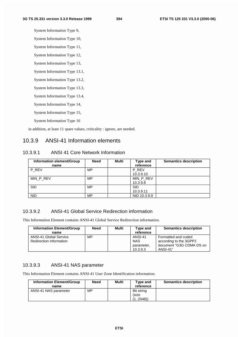
ETSI
ETSI TS 125 331 V3.3.0 (2000-06)3943G TS 25.331 version 3.3.0 Release 1999
System Information Type 9,
System Information Type 10,
System Information Type 11,
System Information Type 12,
System Information Type 13,
System Information Type 13.1,
System Information Type 13.2,
System Information Type 13.3,
System Information Type 13.4,
System Information Type 14,
System Information Type 15,
System Information Type 16
in addition, at least 11 spare values, criticality : ignore, are needed.
10.3.9 ANSI-41 Information elements
10.3.9.1 ANSI 41 Core Network Information
Information element/Groupname
Need Multi Type andreference
Semantics description
P_REV MP P_REV10.3.9.10
MIN_P_REV MP MIN_P_REV10.3.9.8
SID MP SID10.3.9.11
NID MP NID 10.3.9.9
10.3.9.2 ANSI-41 Global Service Redirection information
This Information Element contains ANSI-41 Global Service Redirection information.
Information Element/Groupname
Need Multi Type andreference
Semantics description
ANSI-41 Global ServiceRedirection information
MP ANSI-41NASparameter,10.3.9.3
Formatted and codedaccording to the 3GPP2document "G3G CDMA DS onANSI-41"
10.3.9.3 ANSI-41 NAS parameter
This Information Element contains ANSI-41 User Zone Identification information.
Information Element/Groupname
Need Multi Type andreference
Semantics description
ANSI-41 NAS parameter MP Bit string(size(1..2048))

ETSI
ETSI TS 125 331 V3.3.0 (2000-06)3953G TS 25.331 version 3.3.0 Release 1999
10.3.9.4 ANSI-41 NAS system information
This Information Element contains ANSI-41 system information.
Information Element/Groupname
Need Multi Type andreference
Semantics description
NAS (ANSI-41) systeminformation
MP ANSI-41NASparameter,10.3.9.3
Formatted and codedaccording to the 3GPP2document "G3G CDMA DS onANSI-41"
10.3.9.5 ANSI-41 Private Neighbor List information
This Information Element contains ANSI-41 Private Neighbor List information.
Information Element/Groupname
Need Multi Type andreference
Semantics description
ANSI-41 Private Neighbor Listinformation
MP ANSI-41NASparameter,10.3.9.3
Formatted and codedaccording to the 3GPP2document "G3G CDMA DS onANSI-41"
10.3.9.6 ANSI-41 RAND information
This Information Element contains ANSI-41 RAND information.
Information Element/Groupname
Need Multi Type andreference
Semantics description
ANSI-41 RAND information MP ANSI-41NASparameter,10.3.9.3
Formatted and codedaccording to the 3GPP2document "G3G CDMA DS onANSI-41"
10.3.9.7 ANSI-41 User Zone Identification information
This Information Element contains ANSI-41 User Zone Identification information.
Information Element/Groupname
Need Multi Type andreference
Semantics description
ANSI-41 User ZoneIdentification information
MP ANSI-41NASparameter,10.3.9.3
Formatted and codedaccording to the 3GPP2document "G3G CDMA DS onANSI-41"
10.3.9.8 MIN_P_REV
This Information Element contains minimum protocol revision level.
Information Element/Groupname
Need Multi Type andreference
Semantics description
MIN_P_REV MP Bitstring (8) Minimum protocol revisionlevel
10.3.9.9 NID
This Information Element contains Network identification.

ETSI
ETSI TS 125 331 V3.3.0 (2000-06)3963G TS 25.331 version 3.3.0 Release 1999
Information Element/Groupname
Need Multi Type andreference
Semantics description
NID MP Bitstring (16) Network identification
10.3.9.10 P_REV
This Information Element contains protocol revision level.
Information Element/Groupname
Need Multi Type andreference
Semantics description
P_REV MP Bitstring (8) Protocol revision level
10.3.9.11 SID
This Information Element contains System identification.
Information Element/Groupname
Need Multi Type andreference
Semantics description
SID MP Bitstring (15) System identification
10.3.10 Multiplicity values and type constraint values
The following table includes constants that are either used as multi bounds (name starting with "max") or as high or lowvalue in a type specification (name starting with "lo" or "hi"). Constants are specified only for values appearing morethan once in the RRC specification. In case a constant is related to one or more other constants, an expression isincluded in the "value" column instead of the actual value.

ETSI
ETSI TS 125 331 V3.3.0 (2000-06)3973G TS 25.331 version 3.3.0 Release 1999
Constant Explanation ValueCN informationmaxCNdomains Maximum number of CN domains 4maxSignallingFlow Maximum number of flow identifiers 16UTRAN mobilityinformationmaxRAT Maximum number or Radio Access Technologies maxOtherRAT + 1maxOtherRAT Maximum number or other Radio Access Technologies 15maxURA Maximum number of URAs in a cell 8maxInterSysMessages Maximum number of Inter System Messages 4maxRABsetup Maximum number of RABs to be established 16UE informationmaxPDCPalgoType Maximum number of PDCP algorithm types 8maxDRACclasses Maximum number of UE classes which would require
different DRAC parameters8
maxFrequencybands Maximum number of frequency bands supported by the UEas defined in 25.102
4
maxPage1 Number of Ues paged in the Paging Type 1 message 8maxSystemCapability Maximum number of system specific capabilities that can be
requested in one message.16
RB informationmaxPredefConfig Maximum number of predefined configurations 16maxRB Maximum number of RBs 32maxSRBsetup Maximum number of signalling RBs to be established 8maxRBperRAB Maximum number of RBs per RAB 8maxRBallRABs Maximum number of non signalling RBs 27maxRBMuxOptions Maximum number of RB multiplexing options 8maxLoCHperRLC Maximum number of logical channels per RLC entity 2TrCH informationmaxTrCH Maximum number of transport channels used in one
direction (UL or DL)32
maxTrCHpreconf Maximum number of preconfigured Transport channels, perdirection
16
maxCCTrCH Maximum number of CCTrCHs 8maxTF Maximum number of different transport formats that can be
included in the Transport format set for one transportchannel
32
maxTF-CPCH Maximum number of TFs in a CPCH set 16maxTFC Maximum number of Transport Format Combinations 1024maxTFCI-1-Combs Maximum number of TFCI (field 1) combinations 512maxTFCI-2-Combs Maximum number of TFCI (field 2) combinations 512maxCPCHsets Maximum number of CPCH sets per Node B 16maxSIBsegm Maximum number of complete system information blocks per
SYSTEM INFORMATION message16
maxSIB Maximum number of references to other system informationblocks.
32
maxSIB-FACH Maximum number of references to system information blockson the FACH
8
PhyCH informationmaxSubCh Maximum number of sub-channels on PRACH 12maxPCPCH-APsubCH Maximum number of available sub-channels for AP signature
on PCPCH12
maxPCPCH-CDsubCH Maximum number of available sub-channels for CDsignature on PCPCH
12
maxSig Maximum number of signatures on PRACH 16maxPCPCH-APsig Maximum number of available signatures for AP on PCPCH 16maxPCPCH-CDsig Maximum number of available signatures for CD on PCPCH 16maxAC Maximum number of access classes 16maxASC Maximum number of access service classes 8maxASCmap Maximum number of access class to access service classes
mappings7
maxASCpersist Maximum number of access service classes for whichpersistence scaling factors are specified
6
maxPRACH Maximum number of PRACHs in a cell 16

ETSI
ETSI TS 125 331 V3.3.0 (2000-06)3983G TS 25.331 version 3.3.0 Release 1999
maxFACH Maximum number of FACHs mapped onto one secondaryCCPCHs
8
maxRL Maximum number of radio links 8maxSCCPCH Maximum number of secondary CCPCHs per cell 16maxDPDCH-UL Maximum number of DPDCHs per cell 6maxDPCH-DLchan Maximum number of channelisation codes used for DL
DPCH8
maxDPCHcodesPerTS Maximum number of codes for one timeslots (TDD) 16maxPUSCH Maximum number of PUSCHs (8)maxPDSCH Maximum number of PDSCHs 8maxPDSCHcodes Maximum number of codes for PDSCH 16maxPDSCH-TFCIgroups Maximum number of TFCI groups for PDSCH 256maxPDSCHcodeGroups Maximum number of code groups for PDSCH 256maxPCPCHs Maximum number of PCPCH channels in a CPCH Set 64maxPCPCH-SF Maximum number of available SFs on PCPCH 7maxTS Maximum number of timeslots used in one direction (UL or
DL)14
Measurement informationmaxAdditionalMeas Maximum number of additional measurements for a given
measurement identity4
maxMeasEvent Maximum number of events that can be listed inmeasurement reporting criteria
8
maxMeasParEvent Maximum number of measurement parameters (e.g.thresholds) per event
2
maxMeasIntervals Maximum number of intervals that define the mappingfunction between the measurements for the cell quality Q ofa cell and the representing quality value
1
maxCellMeas Maximum number of cells to measure 32maxFreq Maximum number of frequencies to measure 8maxSat Maximum number of satellites to measure 16HiRM Maximum number that could be set as rate matching
attribute for a transport channel256

ETSI
ETSI TS 125 331 V3.3.0 (2000-06)3993G TS 25.331 version 3.3.0 Release 1999
11 Message and Information element abstract syntax(with ASN.1)
This clause contains definitions for RRC PDUs and IEs using a subset of ASN.1 as specified in TR 25.921. PDU and IEdefinitions are grouped into separate ASN.1 modules.
NOTE: The proposal is to keep both clause 10 and 11 (at least until all messages and information elements arefully discussed and agreed by 3GPP RAN WG2). Clause 10 is intended to give an abstract description (inEnglish) of the messages and information elements whereas clause 11 should contain the exact normativedefinitions with all necessary details.
11.1 General message structureClass-definitions DEFINITIONS AUTOMATIC TAGS ::=
BEGIN
IMPORTS
ActiveSetUpdate,ActiveSetUpdateComplete,ActiveSetUpdateFailure,CellUpdate,CellUpdateConfirm,CounterCheck,CounterCheckResponse,DownlinkDirectTransfer,DownlinkOuterLoopControl,HandoverToUTRANCommand,HandoverToUTRANComplete,InitialDirectTransfer,InterSystemHandoverCommand,InterSystemHandoverFailure,MeasurementControl,MeasurementControlFailure,MeasurementReport,PagingType1,PagingType2,PhysicalChannelReconfiguration,PhysicalChannelReconfigurationComplete,PhysicalChannelReconfigurationFailure,PhysicalSharedChannelAllocation,PUSCHCapacityRequest,RadioBearerReconfiguration,RadioBearerReconfigurationComplete,RadioBearerReconfigurationFailure,RadioBearerRelease,RadioBearerReleaseComplete,RadioBearerReleaseFailure,RadioBearerSetup,RadioBearerSetupComplete,RadioBearerSetupFailure,RNTIReallocation,RNTIReallocationComplete,RNTIReallocationFailure,RRCConnectionReEstablishment,RRCConnectionReEstablishment-CCCH,RRCConnectionReEstablishmentComplete,RRCConnectionReEstablishmentRequest,RRCConnectionReject,RRCConnectionRelease,RRCConnectionRelease-CCCH,RRCConnectionReleaseComplete,RRCConnectionReleaseComplete-CCCH,RRCConnectionRequest,RRCConnectionSetup,RRCConnectionSetupComplete,RRCStatus,SecurityModeCommand,SecurityModeComplete,

ETSI
ETSI TS 125 331 V3.3.0 (2000-06)4003G TS 25.331 version 3.3.0 Release 1999
SecurityModeFailure,SignallingConnectionRelease,SignallingConnectionReleaseRequest,SystemInformation-BCH,SystemInformation-FACH,SystemInformationChangeIndication,TransportChannelReconfiguration,TransportChannelReconfigurationComplete,TransportChannelReconfigurationFailure,TransportFormatCombinationControl,TransportFormatCombinationControlFailure,UECapabilityEnquiry,UECapabilityInformation,UECapabilityInformationConfirm,UplinkDirectTransfer,UplinkPhysicalChannelControl,URAUpdate,URAUpdateConfirm,URAUpdateConfirm-CCCH
FROM PDU-definitions
IntegrityCheckInfoFROM UserEquipment-IEs;
--**************************************************************---- Downlink DCCH messages----**************************************************************
DL-DCCH-Message ::= SEQUENCE {integrityCheckInfo IntegrityCheckInfo OPTIONAL,message DL-DCCH-MessageType
}
DL-DCCH-MessageType ::= CHOICE {activeSetUpdate ActiveSetUpdate,cellUpdateConfirm CellUpdateConfirm,counterCheck CounterCheck,downlinkDirectTransfer DownlinkDirectTransfer,downlinkOuterLoopControl DownlinkOuterLoopControl,interSystemHandoverCommand InterSystemHandoverCommand,measurementControl MeasurementControl,pagingType2 PagingType2,physicalChannelReconfiguration PhysicalChannelReconfiguration,physicalSharedChannelAllocation PhysicalSharedChannelAllocation,radioBearerReconfiguration RadioBearerReconfiguration,radioBearerRelease RadioBearerRelease,radioBearerSetup RadioBearerSetup,rntiReallocation RNTIReallocation,rrcConnectionReEstablishment RRCConnectionReEstablishment,rrcConnectionRelease RRCConnectionRelease,securityModeCommand SecurityModeCommand,signallingConnectionRelease SignallingConnectionRelease,transportChannelReconfiguration TransportChannelReconfiguration,transportFormatCombinationControl TransportFormatCombinationControl,ueCapabilityEnquiry UECapabilityEnquiry,ueCapabilityInformationConfirm UECapabilityInformationConfirm,uplinkPhysicalChannelControl UplinkPhysicalChannelControl,uraUpdateConfirm URAUpdateConfirm,extension NULL
}
--**************************************************************---- Uplink DCCH messages----**************************************************************
UL-DCCH-Message ::= SEQUENCE {integrityCheckInfo IntegrityCheckInfo OPTIONAL,message UL-DCCH-MessageType
}
UL-DCCH-MessageType ::= CHOICE {activeSetUpdateComplete ActiveSetUpdateComplete,activeSetUpdateFailure ActiveSetUpdateFailure,counterCheckResponse CounterCheckResponse,

ETSI
ETSI TS 125 331 V3.3.0 (2000-06)4013G TS 25.331 version 3.3.0 Release 1999
handoverToUTRANComplete HandoverToUTRANComplete,initialDirectTransfer InitialDirectTransfer,interSystemHandoverFailure InterSystemHandoverFailure,measurementControlFailure MeasurementControlFailure,measurementReport MeasurementReport,physicalChannelReconfigurationComplete
PhysicalChannelReconfigurationComplete,physicalChannelReconfigurationFailure
PhysicalChannelReconfigurationFailure,radioBearerReconfigurationComplete RadioBearerReconfigurationComplete,radioBearerReconfigurationFailure RadioBearerReconfigurationFailure,radioBearerReleaseComplete RadioBearerReleaseComplete,radioBearerReleaseFailure RadioBearerReleaseFailure,radioBearerSetupComplete RadioBearerSetupComplete,radioBearerSetupFailure RadioBearerSetupFailure,rntiReallocationComplete RNTIReallocationComplete,rntiReallocationFailure RNTIReallocationFailure,rrcConnectionReEstablishmentComplete
RRCConnectionReEstablishmentComplete,rrcConnectionReleaseComplete RRCConnectionReleaseComplete,rrcConnectionSetupComplete RRCConnectionSetupComplete,rrcStatus RRCStatus,securityModeComplete SecurityModeComplete,securityModeFailure SecurityModeFailure,signallingConnectionReleaseRequest SignallingConnectionReleaseRequest,transportChannelReconfigurationComplete
TransportChannelReconfigurationComplete,transportChannelReconfigurationFailure
TransportChannelReconfigurationFailure,transportFormatCombinationControlFailure
TransportFormatCombinationControlFailure,ueCapabilityInformation UECapabilityInformation,uplinkDirectTransfer UplinkDirectTransfer,extension NULL
}
--**************************************************************---- Downlink CCCH messages----**************************************************************
DL-CCCH-Message ::= SEQUENCE {integrityCheckInfo IntegrityCheckInfo OPTIONAL,message DL-CCCH-MessageType
}
DL-CCCH-MessageType ::= CHOICE {rrcConnectionReEstablishment RRCConnectionReEstablishment-CCCH,rrcConnectionReject RRCConnectionReject,rrcConnectionRelease RRCConnectionRelease-CCCH,rrcConnectionSetup RRCConnectionSetup,uraUpdateConfirm URAUpdateConfirm-CCCH,extension NULL
}
--**************************************************************---- Uplink CCCH messages----**************************************************************
UL-CCCH-Message ::= SEQUENCE {integrityCheckInfo IntegrityCheckInfo OPTIONAL,message UL-CCCH-MessageType
}
UL-CCCH-MessageType ::= CHOICE {cellUpdate CellUpdate,rrcConnectionReEstablishmentRequest RRCConnectionReEstablishmentRequest,rrcConnectionReleaseComplete RRCConnectionReleaseComplete-CCCH,rrcConnectionRequest RRCConnectionRequest,uraUpdate URAUpdate,extension NULL
}
--**************************************************************--

ETSI
ETSI TS 125 331 V3.3.0 (2000-06)4023G TS 25.331 version 3.3.0 Release 1999
-- PCCH messages----**************************************************************
PCCH-Message ::= SEQUENCE {message PCCH-MessageType
}
PCCH-MessageType ::= CHOICE {pagingType1 PagingType1,extension NULL
}
--**************************************************************---- Downlink SHCCH messages----**************************************************************
DL-SHCCH-Message ::= SEQUENCE {integrityCheckInfo IntegrityCheckInfo OPTIONAL,message DL-SHCCH-MessageType
}
DL-SHCCH-MessageType ::= CHOICE {physicalSharedChannelAllocation PhysicalSharedChannelAllocation,extension NULL
}
--**************************************************************---- Uplink SHCCH messages----**************************************************************
UL-SHCCH-Message ::= SEQUENCE {integrityCheckInfo IntegrityCheckInfo OPTIONAL,message UL-SHCCH-MessageType
}
UL-SHCCH-MessageType ::= CHOICE {puschCapacityRequest PUSCHCapacityRequest,extension NULL
}
--**************************************************************---- Handover to UTRAN command----**************************************************************
HO-ToUTRAN-CommandMessage ::= SEQUENCE {message HandoverToUTRANCommand
}
--**************************************************************---- BCCH messages sent on FACH----**************************************************************
BCCH-FACH-Message ::= SEQUENCE {message BCCH-FACH-MessageType
}
BCCH-FACH-MessageType ::= CHOICE {systemInformation SystemInformation-FACH,systemInformationChangeIndication SystemInformationChangeIndication,extension NULL
}
--**************************************************************---- BCCH messages sent on BCH----**************************************************************
BCCH-BCH-Message ::= SEQUENCE {

ETSI
ETSI TS 125 331 V3.3.0 (2000-06)4033G TS 25.331 version 3.3.0 Release 1999
message SystemInformation-BCH}
END
11.2 PDU definitions--**************************************************************---- TABULAR: The message type and integrity check info are not-- visible in this module as they are defined in the class module.-- Also, all FDD/TDD specific choices have the FDD option first-- and TDD second, just for consistency.----**************************************************************
PDU-definitions DEFINITIONS AUTOMATIC TAGS ::=
BEGIN
--**************************************************************---- IE parameter types from other modules----**************************************************************
IMPORTS
CN-DomainIdentity,CN-InformationInfo,FlowIdentifier,NAS-Message,PagingRecordTypeID,ServiceDescriptor,SignallingFlowInfoList
FROM CoreNetwork-IEs
URA-IdentityFROM UTRANMobility-IEs
ActivationTime,C-RNTI,CapabilityUpdateRequirement,CellUpdateCause,CipheringAlgorithm,CipheringModeInfo,DRX-Indicator,EstablishmentCause,FailureCauseWithProtErr,HyperFrameNumber,InitialUE-Identity,IntegrityProtActivationInfo,IntegrityProtectionModeInfo,PagingCause,PagingRecordList,ProtocolErrorIndicator,ProtocolErrorIndicatorWithInfo,Re-EstablishmentTimer,RedirectionInfo,RejectionCause,ReleaseCause,RRC-MessageTX-Count,SecurityCapability,STARTList,U-RNTI,U-RNTI-Short,UE-RadioAccessCapability,URA-UpdateCause,UTRAN-DRX-CycleLengthCoefficient,WaitTime
FROM UserEquipment-IEs
PredefinedConfigIdentity,RAB-Info,RAB-InformationSetupList,RB-ActivationTimeInfo,RB-ActivationTimeInfoList,

ETSI
ETSI TS 125 331 V3.3.0 (2000-06)4043G TS 25.331 version 3.3.0 Release 1999
RB-COUNT-C-InformationList,RB-COUNT-C-MSB-InformationList,RB-IdentityList,RB-InformationAffectedList,RB-InformationReconfigList,RB-InformationReleaseList,RB-InformationSetupList,RB-WithPDCP-InfoList,SRB-InformationSetupList,SRB-InformationSetupList2
FROM RadioBearer-IEs
CPCH-SetID,DL-AddReconfTransChInfo2List,DL-AddReconfTransChInfoList,DL-CommonTransChInfo,DL-DeletedTransChInfoList,DRAC-StaticInformationList,TFC-Subset,UL-AddReconfTransChInfoList,UL-CommonTransChInfo,UL-DeletedTransChInfoList
FROM TransportChannel-IEs
AllocationPeriodInfo,CCTrCH-PowerControlInfo,ConstantValue,CPCH-SetInfo,DL-CommonInformation,DL-CommonInformationPost,DL-InformationPerRL,DL-InformationPerRL-List,DL-InformationPerRL-ListPost,DL-DPCH-PowerControlInfo,DL-OuterLoopControl,DL-PDSCH-Information,DPCH-CompressedModeStatusInfo,FrequencyInfo,IndividualTS-InterferenceList,MaxAllowedUL-TX-Power,PDSCH-Info,PRACH-RACH-Info,PrimaryCCPCH-TX-Power,PUSCH-CapacityAllocationInfo,RL-AdditionInformationList,RL-RemovalInformationList,SSDT-Information,TFC-ControlDuration,TimeslotList,TX-DiversityMode,UL-ChannelRequirement,UL-DPCH-Info,UL-DPCH-InfoPost,UL-TimingAdvance
FROM PhysicalChannel-IEs
AdditionalMeasurementID-List,EventResults,MeasuredResults,MeasuredResultsList,MeasuredResultsOnRACH,MeasurementCommand,MeasurementIdentityNumber,MeasurementReportingMode,PrimaryCCPCH-RSCP,TimeslotListWithISCP,TrafficVolumeMeasuredResultsList
FROM Measurement-IEs
BCCH-ModificationInfo,InterSystemHO-Failure,InterSystemMessage,ProtocolErrorInformation,SegCount,SegmentIndex,SFN-Prime,SIB-Data-fixed,SIB-Data-variable,

ETSI
ETSI TS 125 331 V3.3.0 (2000-06)4053G TS 25.331 version 3.3.0 Release 1999
SIB-TypeFROM Other-IEs
maxSIBsegmFROM Constant-definitions;
-- ***************************************************---- ACTIVE SET UPDATE (FDD only)---- ***************************************************
ActiveSetUpdate ::= SEQUENCE {-- User equipment IEs
integrityProtectionModeInfo IntegrityProtectionModeInfo OPTIONAL,cipheringModeInfo CipheringModeInfo OPTIONAL,activationTime ActivationTime OPTIONAL,newU-RNTI U-RNTI OPTIONAL,
-- Core network IEscn-InformationInfo CN-InformationInfo OPTIONAL,
-- Radio bearer IEsrb-WithPDCP-InfoList RB-WithPDCP-InfoList OPTIONAL,
-- Physical channel IEsmaxAllowedUL-TX-Power MaxAllowedUL-TX-Power OPTIONAL,rl-AdditionInformationList RL-AdditionInformationList OPTIONAL,rl-RemovalInformationList RL-RemovalInformationList OPTIONAL,tx-DiversityMode TX-DiversityMode OPTIONAL,ssdt-Information SSDT-Information OPTIONAL,
-- Extension mechanism for non- release99 informationcriticalExtension SEQUENCE {} OPTIONAL,nonCriticalExtensions SEQUENCE {} OPTIONAL
}
-- ***************************************************---- ACTIVE SET UPDATE COMPLETE (FDD only)---- ***************************************************
ActiveSetUpdateComplete ::= SEQUENCE {-- User equipment IEs
ul-IntegProtActivationInfo IntegrityProtActivationInfo OPTIONAL,-- Radio bearer IEs
rb-UL-CiphActivationTimeInfo RB-ActivationTimeInfo OPTIONAL,rb-WithPDCP-InfoList RB-WithPDCP-InfoList OPTIONAL,
-- Extension mechanism for non- release99 informationnonCriticalExtensions SEQUENCE {} OPTIONAL
}
-- ***************************************************---- ACTIVE SET UPDATE FAILURE (FDD only)---- ***************************************************
ActiveSetUpdateFailure ::= SEQUENCE {-- User equipment IEs
failureCause FailureCauseWithProtErr,-- Extension mechanism for non- release99 information
nonCriticalExtensions SEQUENCE {} OPTIONAL}
-- ***************************************************---- CELL UPDATE---- ***************************************************
CellUpdate ::= SEQUENCE {-- User equipment IEs
u-RNTI U-RNTI,hyperFrameNumber HyperFrameNumber,am-RLC-ErrorIndicationC-plane BOOLEAN,am-RLC-ErrorIndicationU-plane BOOLEAN,cellUpdateCause CellUpdateCause,protocolErrorIndicator ProtocolErrorIndicatorWithInfo,-- TABULAR: Protocol error information is nested in-- ProtocolErrorIndicatorWithInfo.

ETSI
ETSI TS 125 331 V3.3.0 (2000-06)4063G TS 25.331 version 3.3.0 Release 1999
-- Measurement IEsmeasuredResultsOnRACH MeasuredResultsOnRACH OPTIONAL,
-- Extension mechanism for non- release99 informationnonCriticalExtensions SEQUENCE {} OPTIONAL
}
-- ***************************************************---- CELL UPDATE CONFIRM---- ***************************************************
CellUpdateConfirm ::= SEQUENCE {-- User equipment IEs
integrityProtectionModeInfo IntegrityProtectionModeInfo OPTIONAL,cipheringModeInfo CipheringModeInfo OPTIONAL,new-U-RNTI U-RNTI OPTIONAL,new-C-RNTI C-RNTI OPTIONAL,drx-Indicator DRX-Indicator,utran-DRX-CycleLengthCoeff UTRAN-DRX-CycleLengthCoefficient OPTIONAL,rlc-ResetIndicatorC-Plane BOOLEAN,rlc-ResetIndicatorU-Plane BOOLEAN,
-- CN information elementscn-InformationInfo CN-InformationInfo OPTIONAL,
-- UTRAN mobility IEsura-Identity URA-Identity OPTIONAL,
-- Radio bearer IEsrb-WithPDCP-InfoList RB-WithPDCP-InfoList OPTIONAL,
-- Physical channel IEsmaxAllowedUL-TX-Power MaxAllowedUL-TX-Power OPTIONAL,prach-RACH-Info PRACH-RACH-Info OPTIONAL,dl-InformationPerRL DL-InformationPerRL OPTIONAL,
-- Extension mechanism for non- release99 informationcriticalExtension SEQUENCE {} OPTIONAL,nonCriticalExtensions SEQUENCE {} OPTIONAL
}
-- ***************************************************---- COUNTER CHECK---- ***************************************************
CounterCheck ::= SEQUENCE {-- Radio bearer IEs
rb-COUNT-C-MSB-InformationList RB-COUNT-C-MSB-InformationList,-- Extension mechanism for non- release99 information
criticalExtension SEQUENCE {} OPTIONAL,nonCriticalExtensions SEQUENCE {} OPTIONAL
}
-- ***************************************************---- COUNTER CHECK RESPONSE---- ***************************************************
CounterCheckResponse ::= SEQUENCE {-- Radio bearer IEs
rb-COUNT-C-InformationList RB-COUNT-C-InformationList OPTIONAL,-- Extension mechanism for non- release99 information
nonCriticalExtensions SEQUENCE {} OPTIONAL}
-- ***************************************************---- DOWNLINK DIRECT TRANSFER---- ***************************************************
DownlinkDirectTransfer ::= SEQUENCE {-- Core network IEs
cn-DomainIdentity CN-DomainIdentity,nas-Message NAS-Message,
-- Extension mechanism for non- release99 informationcriticalExtension SEQUENCE {} OPTIONAL,nonCriticalExtensions SEQUENCE {} OPTIONAL
}

ETSI
ETSI TS 125 331 V3.3.0 (2000-06)4073G TS 25.331 version 3.3.0 Release 1999
-- ***************************************************---- DOWNLINK OUTER LOOP CONTROL---- ***************************************************
DownlinkOuterLoopControl ::= SEQUENCE {-- Physical channel IEs
dl-OuterLoopControl DL-OuterLoopControl,dl-DPCH-PowerControlInfo DL-DPCH-PowerControlInfo OPTIONAL,
-- Extension mechanism for non- release99 informationcriticalExtension SEQUENCE {} OPTIONAL,nonCriticalExtensions SEQUENCE {} OPTIONAL
}
-- ***************************************************---- HANDOVER TO UTRAN COMMAND---- ***************************************************
HandoverToUTRANCommand ::= SEQUENCE {-- User equipment IEs
new-U-RNTI U-RNTI-Short,activationTime ActivationTime OPTIONAL,cipheringAlgorithm CipheringAlgorithm OPTIONAL,
-- Radio bearer IEsrab-Info RAB-Info,
-- Specification mode informationspecificationMode CHOICE {
complete SEQUENCE {re-EstablishmentTimer Re-EstablishmentTimer,srb-InformationSetupList SRB-InformationSetupList,rb-InformationSetupList RB-InformationSetupList,ul-CommonTransChInfo UL-CommonTransChInfo,ul-AddReconfTransChInfoList UL-AddReconfTransChInfoList,dl-CommonTransChInfo DL-CommonTransChInfo,dl-AddReconfTransChInfoList DL-AddReconfTransChInfoList,ul-DPCH-Info UL-DPCH-Info,modeSpecificInfo CHOICE {
fdd SEQUENCE {dl-CommonInformation DL-CommonInformation,dl-PDSCH-Information DL-PDSCH-Information OPTIONAL,cpch-SetInfo CPCH-SetInfo OPTIONAL
},tdd NULL
},dl-InformationPerRL-List DL-InformationPerRL-List
},preconfiguration SEQUENCE {
predefinedConfigIdentity PredefinedConfigIdentity,ul-DPCH-Info UL-DPCH-InfoPost,modeSpecificInfo CHOICE {
fdd SEQUENCE {dl-CommonInformationPost DL-CommonInformationPost
},tdd NULL
},dl-InformationPerRL-List DL-InformationPerRL-ListPost
}},
-- Physical channel IEsfrequencyInfo FrequencyInfo,maxAllowedUL-TX-Power MaxAllowedUL-TX-Power,modeSpecificPhysChInfo CHOICE {
fdd NULL,tdd SEQUENCE {
primaryCCPCH-TX-Power PrimaryCCPCH-TX-Power}
},-- Extension mechanism for non- release99 information
criticalExtension SEQUENCE {} OPTIONAL,nonCriticalExtensions SEQUENCE {} OPTIONAL
}
-- ***************************************************--

ETSI
ETSI TS 125 331 V3.3.0 (2000-06)4083G TS 25.331 version 3.3.0 Release 1999
-- HANDOVER TO UTRAN COMPLETE---- ***************************************************
HandoverToUTRANComplete ::= SEQUENCE {-- User equipment IEs-- TABULAR: the IE below is conditional on history.
startList STARTList OPTIONAL,-- Extension mechanism for non- release99 information
nonCriticalExtensions SEQUENCE {} OPTIONAL}
-- ***************************************************---- INITIAL DIRECT TRANSFER---- ***************************************************
InitialDirectTransfer ::= SEQUENCE {-- Core network IEs
serviceDescriptor ServiceDescriptor,flowIdentifier FlowIdentifier,cn-DomainIdentity CN-DomainIdentity,nas-Message NAS-Message,
-- Measurement IEsmeasuredResultsOnRACH MeasuredResultsOnRACH OPTIONAL,
-- Extension mechanism for non- release99 informationnonCriticalExtensions SEQUENCE {} OPTIONAL
}
-- ***************************************************---- INTER-SYSTEM HANDOVER COMMAND---- ***************************************************
InterSystemHandoverCommand ::= SEQUENCE {-- User equipment IEs
activationTime ActivationTime OPTIONAL,-- Radio bearer IEs
remainingRAB-Info RAB-Info OPTIONAL,-- Other IEs
interSystemMessage InterSystemMessage,-- Extension mechanism for non- release99 information
criticalExtension SEQUENCE {} OPTIONAL,nonCriticalExtensions SEQUENCE {} OPTIONAL
}
-- ***************************************************---- INTER-SYSTEM HANDOVER FAILURE---- ***************************************************
InterSystemHandoverFailure ::= SEQUENCE {-- Other IEs
interSystemHO-Failure InterSystemHO-Failure OPTIONAL,-- Extension mechanism for non- release99 information
nonCriticalExtensions SEQUENCE {} OPTIONAL}
-- ***************************************************---- MEASUREMENT CONTROL---- ***************************************************
MeasurementControl ::= SEQUENCE {-- Measurement IEs
measurementIdentityNumber MeasurementIdentityNumber,measurementCommand MeasurementCommand,-- TABULAR: The measurement type is included in MeasurementCommand.measurementReportingMode MeasurementReportingMode OPTIONAL,additionalMeasurementList AdditionalMeasurementID-List OPTIONAL,
-- Physical channel IEsdpch-CompressedModeStatusInfo DPCH-CompressedModeStatusInfo OPTIONAL,
-- Extension mechanism for non- release99 informationcriticalExtension SEQUENCE {} OPTIONAL,

ETSI
ETSI TS 125 331 V3.3.0 (2000-06)4093G TS 25.331 version 3.3.0 Release 1999
nonCriticalExtensions SEQUENCE {} OPTIONAL}
-- ***************************************************---- MEASUREMENT CONTROL FAILURE---- ***************************************************
MeasurementControlFailure ::= SEQUENCE {-- User equipment IEs
failureCause FailureCauseWithProtErr,-- Extension mechanism for non- release99 information
nonCriticalExtensions SEQUENCE {} OPTIONAL}
-- ***************************************************---- MEASUREMENT REPORT---- ***************************************************
MeasurementReport ::= SEQUENCE {-- Measurement IEs
measurementIdentityNumber MeasurementIdentityNumber,measuredResults MeasuredResults OPTIONAL,additionalMeasuredResults MeasuredResultsList OPTIONAL,eventResults EventResults OPTIONAL,
-- Extension mechanism for non- release99 informationnonCriticalExtensions SEQUENCE {} OPTIONAL
}
-- ***************************************************---- PAGING TYPE 1---- ***************************************************
PagingType1 ::= SEQUENCE {-- User equipment IEs
pagingRecordList PagingRecordList OPTIONAL,-- Other IEs
bcch-ModificationInfo BCCH-ModificationInfo OPTIONAL,-- Extension mechanism for non- release99 information
nonCriticalExtensions SEQUENCE {} OPTIONAL}
-- ***************************************************---- PAGING TYPE 2---- ***************************************************
PagingType2 ::= SEQUENCE {-- User equipment IEs
pagingCause PagingCause,-- Core network IEs
cn-DomainIdentity CN-DomainIdentity,pagingRecordTypeID PagingRecordTypeID,
-- Extension mechanism for non- release99 informationnonCriticalExtensions SEQUENCE {} OPTIONAL
}
-- ***************************************************---- PHYSICAL CHANNEL RECONFIGURATION---- ***************************************************
PhysicalChannelReconfiguration ::= SEQUENCE {-- User equipment IEs
integrityProtectionModeInfo IntegrityProtectionModeInfo OPTIONAL,cipheringModeInfo CipheringModeInfo OPTIONAL,activationTime ActivationTime OPTIONAL,new-U-RNTI U-RNTI OPTIONAL,new-C-RNTI C-RNTI OPTIONAL,drx-Indicator DRX-Indicator,utran-DRX-CycleLengthCoeff UTRAN-DRX-CycleLengthCoefficient OPTIONAL,

ETSI
ETSI TS 125 331 V3.3.0 (2000-06)4103G TS 25.331 version 3.3.0 Release 1999
-- Core network IEscn-InformationInfo CN-InformationInfo OPTIONAL,
-- Radio bearer IEsrb-WithPDCP-InfoList RB-WithPDCP-InfoList OPTIONAL,
-- Physical channel IEsfrequencyInfo FrequencyInfo OPTIONAL,maxAllowedUL-TX-Power MaxAllowedUL-TX-Power OPTIONAL,ul-ChannelRequirement UL-ChannelRequirement OPTIONAL,-- TABULAR: UL-ChannelRequirement contains the choice-- between UL DPCH info and PRACH info for RACH.modeSpecificInfo CHOICE {
fdd SEQUENCE {dl-CommonInformation DL-CommonInformation OPTIONAL,dl-PDSCH-Information DL-PDSCH-Information OPTIONAL,cpch-SetInfo CPCH-SetInfo OPTIONAL
},tdd NULL
},dl-InformationPerRL-List DL-InformationPerRL-List OPTIONAL,
-- Extension mechanism for non- release99 informationcriticalExtension SEQUENCE {} OPTIONAL,nonCriticalExtensions SEQUENCE {} OPTIONAL
}
-- ***************************************************---- PHYSICAL CHANNEL RECONFIGURATION COMPLETE---- ***************************************************
PhysicalChannelReconfigurationComplete ::= SEQUENCE {-- User equipment IEs
ul-IntegProtActivationInfo IntegrityProtActivationInfo OPTIONAL,-- TABULAR: UL-TimingAdvance is applicable for TDD mode only.ul-TimingAdvance UL-TimingAdvance OPTIONAL,
-- Radio bearer IEsrb-UL-CiphActivationTimeInfo RB-ActivationTimeInfo OPTIONAL,rb-WithPDCP-InfoList RB-WithPDCP-InfoList OPTIONAL,
-- Extension mechanism for non- release99 informationnonCriticalExtensions SEQUENCE {} OPTIONAL
}
-- ***************************************************---- PHYSICAL CHANNEL RECONFIGURATION FAILURE---- ***************************************************
PhysicalChannelReconfigurationFailure ::= SEQUENCE {-- User equipment IEs
failureCause FailureCauseWithProtErr,-- Extension mechanism for non- release99 information
nonCriticalExtensions SEQUENCE {} OPTIONAL}
-- ***************************************************---- PHYSICAL SHARED CHANNEL ALLOCATION (TDD only)---- ***************************************************
PhysicalSharedChannelAllocation ::= SEQUENCE {-- User equipment IEs
c-RNTI C-RNTI OPTIONAL,-- Physical channel IEs
ul-TimingAdvance UL-TimingAdvance OPTIONAL,allocationPeriodInfo AllocationPeriodInfo OPTIONAL,pusch-CapacityAllocationInfo PUSCH-CapacityAllocationInfo OPTIONAL,pdsch-Info PDSCH-Info OPTIONAL,timeslotList TimeslotList OPTIONAL,
-- Extension mechanism for non- release99 informationnonCriticalExtensions SEQUENCE {} OPTIONAL
}
-- ***************************************************---- PUSCH CAPACITY REQUEST (TDD only)--

ETSI
ETSI TS 125 331 V3.3.0 (2000-06)4113G TS 25.331 version 3.3.0 Release 1999
-- ***************************************************
PUSCHCapacityRequest ::= SEQUENCE {-- User equipment IEs
c-RNTI C-RNTI OPTIONAL,-- Measurement IEs
trafficVolumeMeasuredResultsListTrafficVolumeMeasuredResultsList,
timeslotListWithISCP TimeslotListWithISCP OPTIONAL,primaryCCPCH-RSCP PrimaryCCPCH-RSCP OPTIONAL,
-- Extension mechanism for non- release99 informationnonCriticalExtensions SEQUENCE {} OPTIONAL
}
-- ***************************************************---- RADIO BEARER RECONFIGURATION---- ***************************************************
RadioBearerReconfiguration ::= SEQUENCE {-- User equipment IEs
integrityProtectionModeInfo IntegrityProtectionModeInfo OPTIONAL,cipheringModeInfo CipheringModeInfo OPTIONAL,activationTime ActivationTime OPTIONAL,new-U-RNTI U-RNTI OPTIONAL,new-C-RNTI C-RNTI OPTIONAL,drx-Indicator DRX-Indicator,utran-DRX-CycleLengthCoeff UTRAN-DRX-CycleLengthCoefficient OPTIONAL,
-- Core network IEscn-InformationInfo CN-InformationInfo OPTIONAL,
-- Radio bearer IEsrb-InformationReconfigList RB-InformationReconfigList,rb-InformationAffectedList RB-InformationAffectedList OPTIONAL,
-- Transport channel IEsul-CommonTransChInfo UL-CommonTransChInfo OPTIONAL,ul-deletedTransChInfoList UL-DeletedTransChInfoList OPTIONAL,ul-AddReconfTransChInfoList UL-AddReconfTransChInfoList OPTIONAL,modeSpecificTransChInfo CHOICE {
fdd SEQUENCE {cpch-SetID CPCH-SetID OPTIONAL,addReconfTransChDRAC-Info DRAC-StaticInformationList OPTIONAL
},tdd NULL
} OPTIONAL,dl-CommonTransChInfo DL-CommonTransChInfo OPTIONAL,dl-DeletedTransChInfoList DL-DeletedTransChInfoList OPTIONAL,dl-AddReconfTransChInfoList DL-AddReconfTransChInfo2List OPTIONAL,
-- Physical channel IEsfrequencyInfo FrequencyInfo OPTIONAL,maxAllowedUL-TX-Power MaxAllowedUL-TX-Power OPTIONAL,ul-ChannelRequirement UL-ChannelRequirement OPTIONAL,modeSpecificPhysChInfo CHOICE {
fdd SEQUENCE {dl-CommonInformation DL-CommonInformation OPTIONAL,dl-PDSCH-Information DL-PDSCH-Information OPTIONAL,cpch-SetInfo CPCH-SetInfo OPTIONAL
},tdd NULL
},dl-InformationPerRL-List DL-InformationPerRL-List,
-- Extension mechanism for non- release99 informationcriticalExtension SEQUENCE {} OPTIONAL,nonCriticalExtensions SEQUENCE {} OPTIONAL
}
-- ***************************************************---- RADIO BEARER RECONFIGURATION COMPLETE---- ***************************************************
RadioBearerReconfigurationComplete ::= SEQUENCE {-- User equipment IEs
ul-IntegProtActivationInfo IntegrityProtActivationInfo OPTIONAL,-- TABULAR: UL-TimingAdvance is applicable for TDD mode only.ul-TimingAdvance UL-TimingAdvance OPTIONAL,
-- Radio bearer IEs

ETSI
ETSI TS 125 331 V3.3.0 (2000-06)4123G TS 25.331 version 3.3.0 Release 1999
rb-UL-CiphActivationTimeInfo RB-ActivationTimeInfo OPTIONAL,-- Extension mechanism for non- release99 information
nonCriticalExtensions SEQUENCE {} OPTIONAL}
-- ***************************************************---- RADIO BEARER RECONFIGURATION FAILURE---- ***************************************************
RadioBearerReconfigurationFailure ::= SEQUENCE {-- User equipment IEs
failureCause FailureCauseWithProtErr,-- Radio bearer IEs
potentiallySuccesfulBearerList RB-IdentityList OPTIONAL,-- Extension mechanism for non- release99 information
nonCriticalExtensions SEQUENCE {} OPTIONAL}
-- ***************************************************---- RADIO BEARER RELEASE---- ***************************************************
RadioBearerRelease ::= SEQUENCE {-- User equipment IEs
integrityProtectionModeInfo IntegrityProtectionModeInfo OPTIONAL,cipheringModeInfo CipheringModeInfo OPTIONAL,activationTime ActivationTime OPTIONAL,new-U-RNTI U-RNTI OPTIONAL,new-C-RNTI C-RNTI OPTIONAL,drx-Indicator DRX-Indicator,utran-DRX-CycleLengthCoeff UTRAN-DRX-CycleLengthCoefficient OPTIONAL,
-- Core network IEscn-InformationInfo CN-InformationInfo OPTIONAL,
-- Radio bearer IEsrb-InformationReleaseList RB-InformationReleaseList,rb-InformationAffectedList RB-InformationAffectedList OPTIONAL,
-- Transport channel IEsul-CommonTransChInfo UL-CommonTransChInfo OPTIONAL,ul-deletedTransChInfoList UL-DeletedTransChInfoList OPTIONAL,ul-AddReconfTransChInfoList UL-AddReconfTransChInfoList OPTIONAL,modeSpecificTransChInfo CHOICE {
fdd SEQUENCE {cpch-SetID CPCH-SetID OPTIONAL,addReconfTransChDRAC-Info DRAC-StaticInformationList OPTIONAL
},tdd NULL
} OPTIONAL,dl-CommonTransChInfo DL-CommonTransChInfo OPTIONAL,dl-DeletedTransChInfoList DL-DeletedTransChInfoList OPTIONAL,dl-AddReconfTransChInfoList DL-AddReconfTransChInfo2List OPTIONAL,
-- Physical channel IEsfrequencyInfo FrequencyInfo OPTIONAL,maxAllowedUL-TX-Power MaxAllowedUL-TX-Power OPTIONAL,ul-ChannelRequirement UL-ChannelRequirement OPTIONAL,modeSpecificPhysChInfo CHOICE {
fdd SEQUENCE {dl-CommonInformation DL-CommonInformation OPTIONAL,dl-PDSCH-Information DL-PDSCH-Information OPTIONAL,cpch-SetInfo CPCH-SetInfo OPTIONAL
},tdd NULL
},dl-InformationPerRL-List DL-InformationPerRL-List OPTIONAL,
-- Extension mechanism for non- release99 informationcriticalExtension SEQUENCE {} OPTIONAL,nonCriticalExtensions SEQUENCE {} OPTIONAL
}
-- ***************************************************---- RADIO BEARER RELEASE COMPLETE---- ***************************************************

ETSI
ETSI TS 125 331 V3.3.0 (2000-06)4133G TS 25.331 version 3.3.0 Release 1999
RadioBearerReleaseComplete ::= SEQUENCE {-- User equipment IEs
ul-IntegProtActivationInfo IntegrityProtActivationInfo OPTIONAL,-- TABULAR: UL-TimingAdvance is applicable for TDD mode only.ul-TimingAdvance UL-TimingAdvance OPTIONAL,
-- Radio bearer IEsrb-UL-CiphActivationTimeInfo RB-ActivationTimeInfo OPTIONAL,rb-WithPDCP-InfoList RB-WithPDCP-InfoList OPTIONAL,
-- Extension mechanism for non- release99 informationnonCriticalExtensions SEQUENCE {} OPTIONAL
}
-- ***************************************************---- RADIO BEARER RELEASE FAILURE---- ***************************************************
RadioBearerReleaseFailure ::= SEQUENCE {-- User equipment IEs
failureCause FailureCauseWithProtErr,-- Radio bearer IEs
potentiallySuccesfulBearerList RB-IdentityList OPTIONAL,-- Extension mechanism for non- release99 information
nonCriticalExtensions SEQUENCE {} OPTIONAL}
-- ***************************************************---- RADIO BEARER SETUP---- ***************************************************
RadioBearerSetup ::= SEQUENCE {-- User equipment IEs
integrityProtectionModeInfo IntegrityProtectionModeInfo OPTIONAL,cipheringModeInfo CipheringModeInfo OPTIONAL,activationTime ActivationTime OPTIONAL,new-U-RNTI U-RNTI OPTIONAL,new-C-RNTI C-RNTI OPTIONAL,drx-Indicator DRX-Indicator,utran-DRX-CycleLengthCoeff UTRAN-DRX-CycleLengthCoefficient OPTIONAL,
-- Core network IEscn-InformationInfo CN-InformationInfo OPTIONAL,
-- Radio bearer IEssrb-InformationSetupList SRB-InformationSetupList OPTIONAL,rab-InformationSetupList RAB-InformationSetupList,rb-InformationAffectedList RB-InformationAffectedList OPTIONAL,
-- Transport channel IEsul-CommonTransChInfo UL-CommonTransChInfo OPTIONAL,ul-deletedTransChInfoList UL-DeletedTransChInfoList OPTIONAL,ul-AddReconfTransChInfoList UL-AddReconfTransChInfoList OPTIONAL,modeSpecificTransChInfo CHOICE {
fdd SEQUENCE {cpch-SetID CPCH-SetID OPTIONAL,addReconfTransChDRAC-Info DRAC-StaticInformationList OPTIONAL
},tdd NULL
} OPTIONAL,dl-CommonTransChInfo DL-CommonTransChInfo OPTIONAL,dl-DeletedTransChInfoList DL-DeletedTransChInfoList OPTIONAL,dl-AddReconfTransChInfoList DL-AddReconfTransChInfoList OPTIONAL,
-- Physical channel IEsfrequencyInfo FrequencyInfo OPTIONAL,maxAllowedUL-TX-Power MaxAllowedUL-TX-Power OPTIONAL,ul-ChannelRequirement UL-ChannelRequirement OPTIONAL,modeSpecificPhysChInfo CHOICE {
fdd SEQUENCE {dl-CommonInformation DL-CommonInformation OPTIONAL,dl-PDSCH-Information DL-PDSCH-Information OPTIONAL,cpch-SetInfo CPCH-SetInfo OPTIONAL
},tdd NULL
},dl-InformationPerRL-List DL-InformationPerRL-List OPTIONAL,
-- Extension mechanism for non- release99 informationcriticalExtension SEQUENCE {} OPTIONAL,nonCriticalExtensions SEQUENCE {} OPTIONAL

ETSI
ETSI TS 125 331 V3.3.0 (2000-06)4143G TS 25.331 version 3.3.0 Release 1999
}
-- ***************************************************---- RADIO BEARER SETUP COMPLETE---- ***************************************************
RadioBearerSetupComplete ::= SEQUENCE {-- User equipment IEs
ul-IntegProtActivationInfo IntegrityProtActivationInfo OPTIONAL,-- TABULAR: UL-TimingAdvance is applicable for TDD mode only.ul-TimingAdvance UL-TimingAdvance OPTIONAL,hyperFrameNumber HyperFrameNumber OPTIONAL,
-- Radio bearer IEsrb-UL-CiphActivationTimeInfo RB-ActivationTimeInfo OPTIONAL,
-- Extension mechanism for non- release99 informationnonCriticalExtensions SEQUENCE {} OPTIONAL
}
-- ***************************************************---- RADIO BEARER SETUP FAILURE---- ***************************************************
RadioBearerSetupFailure ::= SEQUENCE {-- User equipment IEs
failureCause FailureCauseWithProtErr,-- Radio bearer IEs
potentiallySuccesfulBearerList RB-IdentityList OPTIONAL,-- Extension mechanism for non- release99 information
nonCriticalExtensions SEQUENCE {} OPTIONAL}
-- ***************************************************---- RNTI REALLOCATION---- ***************************************************
RNTIReallocation ::= SEQUENCE {-- User equipment IEs
integrityProtectionModeInfo IntegrityProtectionModeInfo OPTIONAL,cipheringModeInfo CipheringModeInfo OPTIONAL,new-U-RNTI U-RNTI OPTIONAL,new-C-RNTI C-RNTI OPTIONAL,drx-Indicator DRX-Indicator,utran-DRX-CycleLengthCoeff UTRAN-DRX-CycleLengthCoefficient OPTIONAL,
-- CN information elementscn-InformationInfo CN-InformationInfo OPTIONAL,
-- Radio bearer IEsrb-WithPDCP-InfoList RB-WithPDCP-InfoList OPTIONAL,
-- Extension mechanism for non- release99 informationnonCriticalExtensions SEQUENCE {} OPTIONAL
}
-- ***************************************************---- RNTI REALLOCATION COMPLETE---- ***************************************************
RNTIReallocationComplete ::= SEQUENCE {-- User equipment IEs
ul-IntegProtActivationInfo IntegrityProtActivationInfo OPTIONAL,-- Radio bearer IEs
rb-UL-CiphActivationTimeInfo RB-ActivationTimeInfo OPTIONAL,rb-WithPDCP-InfoList RB-WithPDCP-InfoList OPTIONAL,
-- Extension mechanism for non- release99 informationnonCriticalExtensions SEQUENCE {} OPTIONAL
}
-- ***************************************************---- RNTI REALLOCATION FAILURE---- ***************************************************

ETSI
ETSI TS 125 331 V3.3.0 (2000-06)4153G TS 25.331 version 3.3.0 Release 1999
RNTIReallocationFailure ::= SEQUENCE {-- UE information elements
failureCause FailureCauseWithProtErr,-- Extension mechanism for non- release99 information
nonCriticalExtensions SEQUENCE {} OPTIONAL}
-- ***************************************************---- RRC CONNECTION RE-ESTABLISHMENT---- ***************************************************
RRCConnectionReEstablishment ::= SEQUENCE {-- User equipment IEs
integrityProtectionModeInfo IntegrityProtectionModeInfo OPTIONAL,cipheringModeInfo CipheringModeInfo OPTIONAL,activationTime ActivationTime OPTIONAL,new-U-RNTI U-RNTI OPTIONAL,new-C-RNTI C-RNTI OPTIONAL,drx-Indicator DRX-Indicator,utran-DRX-CycleLengthCoeff UTRAN-DRX-CycleLengthCoefficient OPTIONAL,rlc-ResetIndicatorC-plane BOOLEAN,rlc-ResetIndicatorU-plane BOOLEAN,
-- Core network IEscn-InformationInfo CN-InformationInfo OPTIONAL,
-- Radio bearer IEssrb-InformationSetupList SRB-InformationSetupList OPTIONAL,rab-InformationSetupList RAB-InformationSetupList OPTIONAL,rb-InformationReleaseList RB-InformationReleaseList OPTIONAL,rb-InformationReconfigList RB-InformationReconfigList OPTIONAL,rb-InformationAffectedList RB-InformationAffectedList OPTIONAL,
-- Transport channel IEsul-CommonTransChInfo UL-CommonTransChInfo OPTIONAL,ul-deletedTransChInfoList UL-DeletedTransChInfoList OPTIONAL,ul-AddReconfTransChInfoList UL-AddReconfTransChInfoList OPTIONAL,modeSpecificTransChInfo CHOICE {
fdd SEQUENCE {cpch-SetID CPCH-SetID OPTIONAL,addReconfTransChDRAC-Info DRAC-StaticInformationList OPTIONAL
},tdd NULL
},dl-CommonTransChInfo DL-CommonTransChInfo OPTIONAL,dl-DeletedTransChInfoList DL-DeletedTransChInfoList OPTIONAL,dl-AddReconfTransChInfoList DL-AddReconfTransChInfoList OPTIONAL,
-- Physical channel IEsfrequencyInfo FrequencyInfo OPTIONAL,maxAllowedUL-TX-Power MaxAllowedUL-TX-Power OPTIONAL,ul-ChannelRequirement UL-ChannelRequirement OPTIONAL,modeSpecificPhysChInfo CHOICE {
fdd SEQUENCE {dl-CommonInformation DL-CommonInformation OPTIONAL,dl-PDSCH-Information DL-PDSCH-Information OPTIONAL,cpch-SetInfo CPCH-SetInfo OPTIONAL
},tdd NULL
},dl-InformationPerRL-List DL-InformationPerRL-List OPTIONAL,
-- Extension mechanism for non- release99 informationcriticalExtension SEQUENCE {} OPTIONAL,nonCriticalExtensions SEQUENCE {} OPTIONAL
}
-- ***************************************************---- RRC CONNECTION RE-ESTABLISHMENT for CCCH---- ***************************************************
RRCConnectionReEstablishment-CCCH ::= SEQUENCE {-- User equipment IEs
u-RNTI U-RNTI,-- The rest of the message is identical to the one sent on DCCH.
rrcConnectionReEstablishment RRCConnectionReEstablishment}

ETSI
ETSI TS 125 331 V3.3.0 (2000-06)4163G TS 25.331 version 3.3.0 Release 1999
-- ***************************************************---- RRC CONNECTION RE-ESTABLISHMENT COMPLETE---- ***************************************************
RRCConnectionReEstablishmentComplete ::= SEQUENCE {-- User equipment IEs
ul-IntegProtActivationInfo IntegrityProtActivationInfo OPTIONAL,-- TABULAR: UL-TimingAdvance is applicable for TDD mode only.ul-TimingAdvance UL-TimingAdvance OPTIONAL,hyperFrameNumber HyperFrameNumber,
-- Radio bearer IEsrb-UL-CiphActivationTimeInfo RB-ActivationTimeInfo OPTIONAL,rb-WithPDCP-InfoList RB-WithPDCP-InfoList OPTIONAL,
-- Extension mechanism for non- release99 informationnonCriticalExtensions SEQUENCE {} OPTIONAL
}
-- ***************************************************---- RRC CONNECTION RE-ESTABLISHMENT REQUEST---- ***************************************************
RRCConnectionReEstablishmentRequest ::= SEQUENCE {-- User equipment IEs
u-RNTI U-RNTI,hyperFrameNumber HyperFrameNumber,am-RLC-ErrorIndicationC-plane BOOLEAN,am-RLC-ErrorIndicationU-plane BOOLEAN,protocolErrorIndicator ProtocolErrorIndicatorWithInfo,-- TABULAR: The IE above is MD in tabular, but making a 2-way choice-- optional wastes one bit (using PER) and produces no additional-- information.
-- Measurement IEsmeasuredResultsOnRACH MeasuredResultsOnRACH OPTIONAL,
-- Extension mechanism for non- release99 informationnonCriticalExtensions SEQUENCE {} OPTIONAL
}
-- ***************************************************---- RRC CONNECTION REJECT---- ***************************************************
RRCConnectionReject ::= SEQUENCE {-- User equipment IEs
initialUE-Identity InitialUE-Identity,rejectionCause RejectionCause,waitTime WaitTime,redirectionInfo RedirectionInfo OPTIONAL,
-- Extension mechanism for non- release99 informationcriticalExtension SEQUENCE {} OPTIONAL,nonCriticalExtensions SEQUENCE {} OPTIONAL
}
-- ***************************************************---- RRC CONNECTION RELEASE---- ***************************************************
RRCConnectionRelease ::= SEQUENCE {-- User equipment IEs
rrc-MessageTX-Count RRC-MessageTX-Count OPTIONAL,-- The IE above is conditional on the UE state.releaseCause ReleaseCause,
-- Extension mechanism for non- release99 informationcriticalExtension SEQUENCE {} OPTIONAL,nonCriticalExtensions SEQUENCE {} OPTIONAL
}
-- ***************************************************---- RRC CONNECTION RELEASE for CCCH--

ETSI
ETSI TS 125 331 V3.3.0 (2000-06)4173G TS 25.331 version 3.3.0 Release 1999
-- ***************************************************
RRCConnectionRelease-CCCH ::= SEQUENCE {-- User equipment IEs
u-RNTI U-RNTI,-- The rest of the message is identical to the one sent on DCCH.
rrcConnectionRelease RRCConnectionRelease}
-- ***************************************************---- RRC CONNECTION RELEASE COMPLETE---- ***************************************************
RRCConnectionReleaseComplete ::= SEQUENCE {-- Extension mechanism for non- release99 information
nonCriticalExtensions SEQUENCE {} OPTIONAL}
-- ***************************************************---- RRC CONNECTION RELEASE COMPLETE for CCCH---- ***************************************************
RRCConnectionReleaseComplete-CCCH ::= SEQUENCE {-- User equipment IEs
u-RNTI U-RNTI,-- The rest of the message is identical to the one sent on DCCH.
rrcConnectionReleaseComplete RRCConnectionReleaseComplete}
-- ***************************************************---- RRC CONNECTION REQUEST---- ***************************************************
RRCConnectionRequest ::= SEQUENCE {-- User equipment IEs
initialUE-Identity InitialUE-Identity,establishmentCause EstablishmentCause,protocolErrorIndicator ProtocolErrorIndicator,-- The IE above is MD, but for compactness reasons no default value-- has been assigned to it.
-- Measurement IEsmeasuredResultsOnRACH MeasuredResultsOnRACH OPTIONAL,
-- Extension mechanism for non- release99 informationnonCriticalExtensions SEQUENCE {} OPTIONAL
}
-- ***************************************************---- RRC CONNECTION SETUP---- ***************************************************
RRCConnectionSetup ::= SEQUENCE {-- User equipment IEs
initialUE-Identity InitialUE-Identity,activationTime ActivationTime OPTIONAL,new-U-RNTI U-RNTI,new-c-RNTI C-RNTI OPTIONAL,utran-DRX-CycleLengthCoeff UTRAN-DRX-CycleLengthCoefficient,capabilityUpdateRequirement CapabilityUpdateRequirement OPTIONAL,-- TABULAR: If the IE is not present, the default value defined in 10.3.3.2 shall-- be used.
-- Radio bearer IEssrb-InformationSetupList SRB-InformationSetupList2,
-- Transport channel IEsul-CommonTransChInfo UL-CommonTransChInfo OPTIONAL,ul-AddReconfTransChInfoList UL-AddReconfTransChInfoList,dl-CommonTransChInfo DL-CommonTransChInfo OPTIONAL,dl-AddReconfTransChInfoList DL-AddReconfTransChInfoList,
-- Physical channel IEsfrequencyInfo FrequencyInfo OPTIONAL,maxAllowedUL-TX-Power MaxAllowedUL-TX-Power OPTIONAL,

ETSI
ETSI TS 125 331 V3.3.0 (2000-06)4183G TS 25.331 version 3.3.0 Release 1999
ul-ChannelRequirement UL-ChannelRequirement OPTIONAL,modeSpecificInfo CHOICE {
fdd SEQUENCE {dl-CommonInformation DL-CommonInformation OPTIONAL
},tdd NULL
},dl-InformationPerRL-List DL-InformationPerRL-List OPTIONAL,
-- Extension mechanism for non- release99 informationcriticalExtension SEQUENCE {} OPTIONAL,nonCriticalExtensions SEQUENCE {} OPTIONAL
}
-- ***************************************************---- RRC CONNECTION SETUP COMPLETE---- ***************************************************
RRCConnectionSetupComplete ::= SEQUENCE {-- User equipment IEs
startList STARTList,ue-RadioAccessCapability UE-RadioAccessCapability,ue-SystemSpecificCapability InterSystemMessage OPTIONAL,
-- Extension mechanism for non- release99 informationnonCriticalExtensions SEQUENCE {} OPTIONAL
}
-- ***************************************************---- RRC STATUS---- ***************************************************
RRCStatus ::= SEQUENCE {-- Other IEs
protocolErrorInformation ProtocolErrorInformation,-- Extension mechanism for non- release99 information
nonCriticalExtensions SEQUENCE {} OPTIONAL}
-- ***************************************************---- SECURITY MODE COMMAND---- ***************************************************
SecurityModeCommand ::= SEQUENCE {-- User equipment IEs
cipheringAlgorithm SecurityCapability,cipheringModeInfo CipheringModeInfo OPTIONAL,integrityProtectionModeInfo IntegrityProtectionModeInfo OPTIONAL,
-- Core network IEscn-DomainIdentity CN-DomainIdentity,
-- Extension mechanism for non- release99 informationcriticalExtension SEQUENCE {} OPTIONAL,nonCriticalExtensions SEQUENCE {} OPTIONAL
}
-- ***************************************************---- SECURITY MODE COMPLETE---- ***************************************************
SecurityModeComplete ::= SEQUENCE {-- User equipment IEs
ul-IntegProtActivationInfo IntegrityProtActivationInfo OPTIONAL,-- Radio bearer IEs
rb-UL-CiphActivationTimeInfo RB-ActivationTimeInfoList OPTIONAL,-- Extension mechanism for non- release99 information
nonCriticalExtensions SEQUENCE {} OPTIONAL}
-- ***************************************************---- SECURITY MODE FAILURE--

ETSI
ETSI TS 125 331 V3.3.0 (2000-06)4193G TS 25.331 version 3.3.0 Release 1999
-- ***************************************************
SecurityModeFailure ::= SEQUENCE {-- User equipment IEs
failureCause FailureCauseWithProtErr,-- Extension mechanism for non- release99 information
nonCriticalExtensions SEQUENCE {} OPTIONAL}
-- ***************************************************---- SIGNALLING CONNECTION RELEASE---- ***************************************************
SignallingConnectionRelease ::= SEQUENCE {-- Core network IEs
signallingFlowInfoList SignallingFlowInfoList,-- Extension mechanism for non- release99 information
criticalExtension SEQUENCE {} OPTIONAL,nonCriticalExtensions SEQUENCE {} OPTIONAL
}
-- ***************************************************---- SIGNALLING CONNECTION RELEASE REQUEST---- ***************************************************
SignallingConnectionReleaseRequest ::= SEQUENCE {-- Core network IEs
signallingFlowInfoList SignallingFlowInfoList,-- Extension mechanism for non- release99 information
nonCriticalExtensions SEQUENCE {} OPTIONAL}
-- ***************************************************---- SYSTEM INFORMATION for BCH---- ***************************************************
SystemInformation-BCH ::= SEQUENCE {-- Other information elements
sfn-Prime SFN-Prime,payload CHOICE {
noSegment NULL,firstSegment FirstSegment,subsequentSegment SubsequentSegment,lastSegment LastSegment,lastAndFirst SEQUENCE {
lastSegment LastSegment,firstSegment FirstSegmentShort
},lastAndComplete SEQUENCE {
completeSIB-List CompleteSIB-List,lastSegment LastSegment
},lastAndCompleteAndFirst SEQUENCE {
lastSegment LastSegment,completeSIB-List CompleteSIB-List,firstSegment FirstSegmentShort
},completeSIB-List CompleteSIB-List,completeAndFirst SEQUENCE {
completeSIB-List CompleteSIB-List,firstSegment FirstSegmentShort
}}
}
-- ***************************************************---- SYSTEM INFORMATION for FACH---- ***************************************************
SystemInformation-FACH ::= SEQUENCE {

ETSI
ETSI TS 125 331 V3.3.0 (2000-06)4203G TS 25.331 version 3.3.0 Release 1999
-- Other information elementspayload CHOICE {
noSegment NULL,firstSegment FirstSegment,subsequentSegment SubsequentSegment,lastSegment LastSegment,lastAndFirst SEQUENCE {
lastSegment LastSegment,firstSegment FirstSegmentShort
},lastAndComplete SEQUENCE {
completeSIB-List CompleteSIB-List,lastSegment LastSegment
},lastAndCompleteAndFirst SEQUENCE {
lastSegment LastSegment,completeSIB-List CompleteSIB-List,firstSegment FirstSegmentShort
},completeSIB-List CompleteSIB-List,completeAndFirst SEQUENCE {
completeSIB-List CompleteSIB-List,firstSegment FirstSegmentShort
}}
}
-- ***************************************************---- First segment---- ***************************************************
FirstSegment ::= SEQUENCE {-- Other information elements
sib-Type SIB-Type,seg-Count SegCount,sib-Data-fixed SIB-Data-fixed
}
-- ***************************************************---- First segment (short)---- ***************************************************
FirstSegmentShort ::= SEQUENCE {-- Other information elements
sib-Type SIB-Type,seg-Count SegCount,sib-Data-variable SIB-Data-variable
}
-- ***************************************************---- Subsequent segment---- ***************************************************
SubsequentSegment ::= SEQUENCE {-- Other information elements
sib-Type SIB-Type,segmentIndex SegmentIndex,sib-Data-fixed SIB-Data-fixed
}
-- ***************************************************---- Last segment---- ***************************************************
LastSegment ::= SEQUENCE {-- Other information elements
sib-Type SIB-Type,segmentIndex SegmentIndex,sib-Data-variable SIB-Data-variable
}

ETSI
ETSI TS 125 331 V3.3.0 (2000-06)4213G TS 25.331 version 3.3.0 Release 1999
-- ***************************************************---- Complete SIB---- ***************************************************
CompleteSIB-List ::= SEQUENCE (SIZE (1..maxSIBsegm)) OFCompleteSIB
CompleteSIB ::= SEQUENCE {-- Other information elements
sib-Type SIB-Type,sib-Data-variable SIB-Data-variable
}
-- ***************************************************---- SYSTEM INFORMATION CHANGE INDICATION---- ***************************************************
SystemInformationChangeIndication ::= SEQUENCE {-- Other IEs
bcch-ModificationInfo BCCH-ModificationInfo,-- Extension mechanism for non- release99 information
nonCriticalExtensions SEQUENCE {} OPTIONAL}
-- ***************************************************---- TRANSPORT CHANNEL RECONFIGURATION---- ***************************************************
TransportChannelReconfiguration ::= SEQUENCE {-- User equipment IEs
integrityProtectionModeInfo IntegrityProtectionModeInfo OPTIONAL,cipheringModeInfo CipheringModeInfo OPTIONAL,activationTime ActivationTime OPTIONAL,new-U-RNTI U-RNTI OPTIONAL,new-C-RNTI C-RNTI OPTIONAL,drx-Indicator DRX-Indicator,utran-DRX-CycleLengthCoeff UTRAN-DRX-CycleLengthCoefficient OPTIONAL,
-- Core network IEscn-InformationInfo CN-InformationInfo OPTIONAL,
-- Radio bearer IEsrb-WithPDCP-InfoList RB-WithPDCP-InfoList OPTIONAL,
-- Transport channel IEsul-CommonTransChInfo UL-CommonTransChInfo OPTIONAL,ul-AddReconfTransChInfoList UL-AddReconfTransChInfoList,modeSpecificTransChInfo CHOICE {
fdd SEQUENCE {cpch-SetID CPCH-SetID OPTIONAL,addReconfTransChDRAC-Info DRAC-StaticInformationList OPTIONAL
},tdd NULL
} OPTIONAL,dl-CommonTransChInfo DL-CommonTransChInfo OPTIONAL,dl-AddReconfTransChInfoList DL-AddReconfTransChInfoList,
-- Physical channel IEsfrequencyInfo FrequencyInfo OPTIONAL,maxAllowedUL-TX-Power MaxAllowedUL-TX-Power OPTIONAL,ul-ChannelRequirement UL-ChannelRequirement OPTIONAL,modeSpecificPhysChInfo CHOICE {
fdd SEQUENCE {dl-CommonInformation DL-CommonInformation OPTIONAL,dl-PDSCH-Information DL-PDSCH-Information OPTIONAL,cpch-SetInfo CPCH-SetInfo OPTIONAL
},tdd NULL
},dl-InformationPerRL-List DL-InformationPerRL-List OPTIONAL,
-- Extension mechanism for non- release99 informationcriticalExtension SEQUENCE {} OPTIONAL,nonCriticalExtensions SEQUENCE {} OPTIONAL
}

ETSI
ETSI TS 125 331 V3.3.0 (2000-06)4223G TS 25.331 version 3.3.0 Release 1999
-- ***************************************************---- TRANSPORT CHANNEL RECONFIGURATION COMPLETE---- ***************************************************
TransportChannelReconfigurationComplete ::= SEQUENCE {-- User equipment IEs
ul-IntegProtActivationInfo IntegrityProtActivationInfo OPTIONAL,-- TABULAR: UL-TimingAdvance is applicable for TDD mode only.ul-TimingAdvance UL-TimingAdvance OPTIONAL,
-- Radio bearer IEsrb-UL-CiphActivationTimeInfo RB-ActivationTimeInfo OPTIONAL,rb-WithPDCP-InfoList RB-WithPDCP-InfoList OPTIONAL,
-- Extension mechanism for non- release99 informationnonCriticalExtensions SEQUENCE {} OPTIONAL
}
-- ***************************************************---- TRANSPORT CHANNEL RECONFIGURATION FAILURE---- ***************************************************
TransportChannelReconfigurationFailure ::= SEQUENCE {-- User equipment IEs
failureCause FailureCauseWithProtErr,-- Extension mechanism for non- release99 information
nonCriticalExtensions SEQUENCE {} OPTIONAL}
-- ***************************************************---- TRANSPORT FORMAT COMBINATION CONTROL---- ***************************************************
TransportFormatCombinationControl ::= SEQUENCE {dpch-TFCS-InUplink TFC-Subset,tfc-ControlDuration TFC-ControlDuration OPTIONAL,-- The information element is not included when transmitting the message-- on the transparent mode signalling DCCH and is optional otherwise-- Extension mechanism for non- release99 information
nonCriticalExtensions SEQUENCE {} OPTIONAL}
-- ***************************************************---- TRANSPORT FORMAT COMBINATION CONTROL FAILURE---- ***************************************************
TransportFormatCombinationControlFailure ::= SEQUENCE {-- User equipment IEs
failureCause FailureCauseWithProtErr,-- Extension mechanism for non- release99 information
nonCriticalExtensions SEQUENCE {} OPTIONAL}
-- ***************************************************---- UE CAPABILITY ENQUIRY---- ***************************************************
UECapabilityEnquiry ::= SEQUENCE {-- User equipment IEs
capabilityUpdateRequirement CapabilityUpdateRequirement,-- Extension mechanism for non- release99 information
criticalExtension SEQUENCE {} OPTIONAL,nonCriticalExtensions SEQUENCE {} OPTIONAL
}
-- ***************************************************---- UE CAPABILITY INFORMATION---- ***************************************************

ETSI
ETSI TS 125 331 V3.3.0 (2000-06)4233G TS 25.331 version 3.3.0 Release 1999
UECapabilityInformation ::= SEQUENCE {-- User equipment IEs
ue-RadioAccessCapability UE-RadioAccessCapability OPTIONAL,-- Other IEs
ue-SystemSpecificCapability InterSystemMessage OPTIONAL,-- Extension mechanism for non- release99 information
nonCriticalExtensions SEQUENCE {} OPTIONAL}
-- ***************************************************---- UE CAPABILITY INFORMATION CONFIRM---- ***************************************************
UECapabilityInformationConfirm ::= SEQUENCE {-- Extension mechanism for non- release99 information
criticalExtension SEQUENCE {} OPTIONAL,nonCriticalExtensions SEQUENCE {} OPTIONAL
}
-- ***************************************************---- UPLINK DIRECT TRANSFER---- ***************************************************
UplinkDirectTransfer ::= SEQUENCE {-- Core network IEs
flowIdentifier FlowIdentifier,nas-Message NAS-Message,
-- Measurement IEsmeasuredResultsOnRACH MeasuredResultsOnRACH OPTIONAL,
-- Extension mechanism for non- release99 informationnonCriticalExtensions SEQUENCE {} OPTIONAL
}
-- ***************************************************---- UPLINK PHYSICAL CHANNEL CONTROL---- ***************************************************
UplinkPhysicalChannelControl ::= SEQUENCE {-- Physical channel IEs
ccTrCH-PowerControlInfo CCTrCH-PowerControlInfo OPTIONAL,timingAdvance UL-TimingAdvance OPTIONAL,individualTS-InterferenceList IndividualTS-InterferenceList OPTIONAL,prach-ConstantValue ConstantValue OPTIONAL,dpch-ConstantValue ConstantValue OPTIONAL,pusch-ConstantValue ConstantValue OPTIONAL,
-- Extension mechanism for non- release99 informationcriticalExtension SEQUENCE {} OPTIONAL,nonCriticalExtensions SEQUENCE {} OPTIONAL
}
-- ***************************************************---- URA UPDATE---- ***************************************************
URAUpdate ::= SEQUENCE {-- User equipment IEs
u-RNTI U-RNTI,ura-UpdateCause URA-UpdateCause,protocolErrorIndicator ProtocolErrorIndicatorWithInfo,
-- Extension mechanism for non- release99 informationnonCriticalExtensions SEQUENCE {} OPTIONAL
}
-- ***************************************************---- URA UPDATE CONFIRM---- ***************************************************

ETSI
ETSI TS 125 331 V3.3.0 (2000-06)4243G TS 25.331 version 3.3.0 Release 1999
URAUpdateConfirm ::= SEQUENCE {-- User equipment IEs
integrityProtectionModeInfo IntegrityProtectionModeInfo OPTIONAL,cipheringModeInfo CipheringModeInfo OPTIONAL,new-U-RNTI U-RNTI OPTIONAL,new-C-RNTI C-RNTI OPTIONAL,drx-Indicator DRX-Indicator,utran-DRX-CycleLengthCoeff UTRAN-DRX-CycleLengthCoefficient OPTIONAL,
-- CN information elementscn-InformationInfo CN-InformationInfo OPTIONAL,
-- UTRAN mobility IEsura-Identity URA-Identity OPTIONAL,
-- Radio bearer IEsrb-WithPDCP-InfoList RB-WithPDCP-InfoList OPTIONAL,
-- Extension mechanism for non- release99 informationcriticalExtension SEQUENCE {} OPTIONAL,nonCriticalExtensions SEQUENCE {} OPTIONAL
}
-- ***************************************************---- URA UPDATE CONFIRM for CCCH---- ***************************************************
URAUpdateConfirm-CCCH ::= SEQUENCE {-- User equipment IEs
u-RNTI U-RNTI,-- The rest of the message is identical to the one sent on DCCH.
uraUpdateConfirm URAUpdateConfirm}
END
11.3 Information element definitions
11.3.1 Core network information elementsCoreNetwork-IEs DEFINITIONS AUTOMATIC TAGS ::=
BEGIN
IMPORTS
CN-DRX-CycleLengthCoefficientFROM UserEquipment-IEs
Min-P-REV,NAS-SystemInformationANSI-41,NID,P-REV,SID
FROM ANSI-41-IEs
maxCNdomains,maxSignallingFlow
FROM Constant-definitions;
CN-DomainIdentity ::= ENUMERATED {cs-domain,ps-domain,not-important,spare1 }
CN-DomainInformation ::= SEQUENCE {cn-DomainIdentity CN-DomainIdentity,cn-DomainSpecificNAS-Info NAS-SystemInformationGSM-MAP
}
CN-DomainInformationList ::= SEQUENCE (SIZE (1..maxCNdomains)) OFCN-DomainInformation
CN-DomainSysInfo ::= SEQUENCE {cn-DomainIdentity CN-DomainIdentity,cn-Type CHOICE {
gsm-MAP NAS-SystemInformationGSM-MAP,

ETSI
ETSI TS 125 331 V3.3.0 (2000-06)4253G TS 25.331 version 3.3.0 Release 1999
ansi-41 NAS-SystemInformationANSI-41},cn-DRX-CycleLengthCoeff CN-DRX-CycleLengthCoefficient
}
CN-DomainSysInfoList ::= SEQUENCE (SIZE (1..maxCNdomains)) OFCN-DomainSysInfo
CN-InformationInfo ::= SEQUENCE {plmn-Identity PLMN-Identity OPTIONAL,cn-CommonGSM-MAP-NAS-SysInfo NAS-SystemInformationGSM-MAP OPTIONAL,cn-DomainInformationList CN-DomainInformationList OPTIONAL
}
Digit ::= INTEGER (0..9)
FlowIdentifier ::= INTEGER (0..63)
IMEI ::= SEQUENCE (SIZE (15)) OFIMEI-Digit
IMEI-Digit ::= INTEGER (0..15)
IMSI-GSM-MAP ::= SEQUENCE (SIZE (6..15)) OFDigit
LAI ::= SEQUENCE {plmn-Identity PLMN-Identity,lac BIT STRING (SIZE (16))
}
MCC ::= SEQUENCE (SIZE (3)) OFDigit
MNC ::= SEQUENCE (SIZE (2..3)) OFDigit
NAS-Message ::= OCTET STRING (SIZE (1..4095))
NAS-SystemInformationGSM-MAP ::= OCTET STRING (SIZE (1..8))
P-TMSI-GSM-MAP ::= BIT STRING (SIZE (32))
PagingRecordTypeID ::= ENUMERATED {imsi-GSM-MAP,tmsi-GSM-MAP-P-TMSI,imsi-DS-41,tmsi-DS-41 }
PLMN-Identity ::= SEQUENCE {mcc MCC,mnc MNC
}
PLMN-Type ::= CHOICE {gsm-MAP SEQUENCE {
plmn-Identity PLMN-Identity},ansi-41 SEQUENCE {
p-REV P-REV,min-P-REV Min-P-REV,sid SID,nid NID
},gsm-MAP-and-ANSI-41 SEQUENCE {
plmn-Identity PLMN-Identity,p-REV P-REV,min-P-REV Min-P-REV,sid SID,nid NID
},spare NULL
}
RAB-Identity ::= CHOICE {gsm-MAP-RAB-Identity BIT STRING (SIZE (8)),ansi-41-RAB-Identity BIT STRING (SIZE (8))
}

ETSI
ETSI TS 125 331 V3.3.0 (2000-06)4263G TS 25.331 version 3.3.0 Release 1999
RAI ::= SEQUENCE {lai LAI,rac RoutingAreaCode
}
RoutingAreaCode ::= BIT STRING (SIZE (8))
ServiceDescriptor ::= CHOICE {gsm-MAP BIT STRING (SIZE (4)),ansi-41 BIT STRING (SIZE (4))
}
SignallingFlowInfoList ::= SEQUENCE (SIZE (1..maxSignallingFlow)) OFFlowIdentifier
TMSI-GSM-MAP ::= BIT STRING (SIZE (32))
END
11.3.2 UTRAN mobility information elementsUTRANMobility-IEs DEFINITIONS AUTOMATIC TAGS ::=
BEGIN
IMPORTS
MaxAllowedUL-TX-PowerFROM PhysicalChannel-IEs
HCS-ServingCellInformation,Q-QualMin,Q-RxlevMin
FROM Measurement-IEs
maxAC,maxMeasIntervals,maxOtherRAT,maxRAT,maxURA
FROM Constant-definitions;
AccessClassBarred ::= ENUMERATED {barred, notBarred }
AccessClassBarredList ::= SEQUENCE (SIZE (maxAC)) OFAccessClassBarred
AllowedIndicator ::= ENUMERATED {allowed, notAllowed }
CellAccessRestriction ::= SEQUENCE {cellBarred CellBarred,cellReservedForOperatorUse ReservedIndicator,cellReservedForSOLSA ReservedIndicator,accessClassBarredList AccessClassBarredList OPTIONAL
}
CellBarred ::= CHOICE {barred SEQUENCE {
intraFreqCellReselectionInd AllowedIndicator,t-Barred T-Barred
},notBarred NULL
}
CellIdentity ::= BIT STRING (SIZE (28))
CellSelectQualityMeasure ::= ENUMERATED {cpich-Ec-N0, cpich-RSCP }
CellSelectReselectInfoSIB-3-4 ::= SEQUENCE {mappingInfo MappingInfo OPTIONAL,modeSpecificInfo CHOICE {
fdd SEQUENCE {cellSelectQualityMeasure CellSelectQualityMeasure,s-Intrasearch S-SearchFDD OPTIONAL,

ETSI
ETSI TS 125 331 V3.3.0 (2000-06)4273G TS 25.331 version 3.3.0 Release 1999
s-Intersearch S-SearchFDD OPTIONAL,s-SearchHCS S-SearchFDD OPTIONAL,rat-List RAT-FDD-InfoList OPTIONAL,q-QualMin Q-QualMin OPTIONAL,q-RxlevMin Q-RxlevMin OPTIONAL
},tdd SEQUENCE {
s-Intrasearch S-SearchTDD OPTIONAL,s-Intersearch S-SearchTDD OPTIONAL,s-SearchHCS S-SearchTDD OPTIONAL,rat-List RAT-TDD-InfoList OPTIONAL,q-RxlevMin Q-RxlevMin OPTIONAL
}}, q-Hyst-S Q-Hyst-S,t-Reselection-S T-Reselection-S,hcs-ServingCellInformation HCS-ServingCellInformation OPTIONAL,maxAllowedUL-TX-Power MaxAllowedUL-TX-Power
}
MapParameter ::= INTEGER (0..99)
Mapping ::= SEQUENCE {rat RAT,mappingFunctionParameterList MappingFunctionParameterList
}
MappingFunctionParameter ::= SEQUENCE {functionType MappingFunctionType,mapParameter1 MapParameter OPTIONAL,mapParameter2 MapParameter,upperLimit UpperLimit OPTIONAL-- The parameter is conditional on the number of repetition
}
MappingFunctionParameterList ::= SEQUENCE (SIZE (1..maxMeasIntervals)) OFMappingFunctionParameter
MappingFunctionType ::= ENUMERATED {linear,functionType2,functionType3,functionType4 }
MappingInfo ::= SEQUENCE (SIZE (1..maxRAT)) OFMapping
-- Actual value = IE value * 2Q-Hyst-S ::= INTEGER (0..20)
RAT ::= ENUMERATED {utra-FDD,utra-TDD,gsm,cdma2000 }
RAT-FDD-Info ::= SEQUENCE {rat-Identifier RAT-Identifier,s-SearchRAT S-SearchFDD,s-HCS-RAT S-SearchFDD OPTIONAL
}
RAT-FDD-InfoList ::= SEQUENCE (SIZE (1..maxOtherRAT)) OFRAT-FDD-Info
RAT-Identifier ::= ENUMERATED {gsm, cdma2000,spare1, spare2 }
RAT-TDD-Info ::= SEQUENCE {rat-Identifier RAT-Identifier,s-SearchRAT S-SearchTDD,s-HCS-RAT S-SearchTDD OPTIONAL
}
RAT-TDD-InfoList ::= SEQUENCE (SIZE (1..maxOtherRAT)) OFRAT-TDD-Info
ReservedIndicator ::= ENUMERATED {

ETSI
ETSI TS 125 331 V3.3.0 (2000-06)4283G TS 25.331 version 3.3.0 Release 1999
reserved,notReserved }
-- Actual value = IE value * 2S-SearchFDD ::= INTEGER (-16..10)
-- Actual value = (IE value * 2) + 1S-SearchTDD ::= INTEGER (-53..45)
T-Barred ::= ENUMERATED {s10, s20, s40, s80,s160, s320, s640, s1280 }
T-Reselection-S ::= INTEGER (0..31)
-- The used range depends on the RAT used.UpperLimit ::= INTEGER (1..91)
URA-Identity ::= BIT STRING (SIZE (16))
URA-IdentityList ::= SEQUENCE (SIZE (1..maxURA)) OFURA-Identity
END
11.3.3 User equipment information elementsUserEquipment-IEs DEFINITIONS AUTOMATIC TAGS ::=
BEGIN
IMPORTS
CN-DomainIdentity,IMEI,IMSI-GSM-MAP,LAI,P-TMSI-GSM-MAP,RAI,TMSI-GSM-MAP
FROM CoreNetwork-IEs
RB-ActivationTimeInfoListFROM RadioBearer-IEs
FrequencyInfo,PowerControlAlgorithm
FROM PhysicalChannel-IEs
InterSystemInfoFROM Measurement-IEs
ProtocolErrorInformationFROM Other-IEs
maxASC,maxCNdomains,maxDRACclasses,maxFrequencybands,maxPage1,maxSystemCapability
FROM Constant-definitions;
ActivationTime ::= INTEGER (0..255)
BackoffControlParams ::= SEQUENCE {n-AP-RetransMax N-AP-RetransMax,n-AccessFails N-AccessFails,nf-BO-NoAICH NF-BO-NoAICH,ns-BO-Busy NS-BO-Busy,nf-BO-AllBusy NF-BO-AllBusy,nf-BO-Mismatch NF-BO-Mismatch,t-CPCH T-CPCH
}
C-RNTI ::= BIT STRING (SIZE (16))
CapabilityUpdateRequirement ::= SEQUENCE {

ETSI
ETSI TS 125 331 V3.3.0 (2000-06)4293G TS 25.331 version 3.3.0 Release 1999
ue-RadioCapabilityUpdateRequirement BOOLEAN,systemSpecificCapUpdateReqList SystemSpecificCapUpdateReqList OPTIONAL
}
CellUpdateCause ::= ENUMERATED {cellReselection,periodicCellUpdate,ul-DataTransmission,pagingResponse,rb-ControlResponse,spare1, spare2, spare3 }
ChipRateCapability ::= ENUMERATED {mcps3-84, mcps1-28 }
CipheringAlgorithm ::= BIT STRING (SIZE (4))
CipheringModeCommand ::= CHOICE {startRestart CipheringAlgorithm,stopCiphering NULL
}
CipheringModeInfo ::= SEQUENCE {cipheringModeCommand CipheringModeCommand,-- TABULAR: The ciphering algorithm is included in-- the CipheringModeCommand.activationTimeForDPCH ActivationTime OPTIONAL,rb-DL-CiphActivationTimeInfo RB-ActivationTimeInfoList OPTIONAL
}
CN-DRX-CycleLengthCoefficient ::= INTEGER (6..12)
CN-PagedUE-Identity ::= CHOICE {imsi-GSM-MAP IMSI-GSM-MAP,tmsi-GSM-MAP TMSI-GSM-MAP,p-TMSI-GSM-MAP P-TMSI-GSM-MAP,imsi-DS-41 IMSI-DS-41,tmsi-DS-41 TMSI-DS-41,spare1 NULL,spare2 NULL,spare3 NULL
}
CompressedModeMeasCapability ::= SEQUENCE {fdd-Measurements BOOLEAN,-- TABULAR: The IEs below are made optional since they are conditional based-- on another information element. Their absence corresponds to the case where-- the condition is not true.tdd-Measurements BOOLEAN OPTIONAL,gsm-Measurements GSM-Measurements OPTIONAL,multiCarrierMeasurements BOOLEAN OPTIONAL
}
CPCH-Parameters ::= SEQUENCE {initialPriorityDelayList InitialPriorityDelayList OPTIONAL,backoffControlParams BackoffControlParams,powerControlAlgorithm PowerControlAlgorithm,-- TABULAR: TPC step size nested inside PowerControlAlgorithmdl-DPCCH-BER DL-DPCCH-BER
}
DL-DPCCH-BER ::= INTEGER (0..63)
DL-PhysChCapabilityFDD ::= SEQUENCE {maxSimultaneousCCTrCH-Count MaxSimultaneousCCTrCH-Count,maxNoDPCH-PDSCH-Codes INTEGER (1..8),maxNoPhysChBitsReceived MaxNoPhysChBitsReceived,supportForSF-512 BOOLEAN,supportOfPDSCH BOOLEAN,simultaneousSCCPCH-DPCH-Reception SimultaneousSCCPCH-DPCH-Reception
}
DL-PhysChCapabilityTDD ::= SEQUENCE {maxSimultaneousCCTrCH-Count MaxSimultaneousCCTrCH-Count,maxTS-PerFrame MaxTS-PerFrame,maxPhysChPerFrame MaxPhysChPerFrame,minimumSF MinimumSF-DL,

ETSI
ETSI TS 125 331 V3.3.0 (2000-06)4303G TS 25.331 version 3.3.0 Release 1999
supportOfPDSCH BOOLEAN}
DL-TransChCapability ::= SEQUENCE {maxNoBitsReceived MaxNoBits,maxConvCodeBitsReceived MaxNoBits,turboDecodingSupport TurboSupport,maxSimultaneousTransChs MaxSimultaneousTransChsDL,maxReceivedTransportBlocks MaxTransportBlocksDL,maxNumberOfTFC-InTFCS MaxNumberOfTFC-InTFCS-DL,maxNumberOfTF MaxNumberOfTF
}
DRAC-SysInfo ::= SEQUENCE {transmissionProbability TransmissionProbability,maximumBitRate MaximumBitRate
}
DRAC-SysInfoList ::= SEQUENCE (SIZE (1..maxDRACclasses)) OFDRAC-SysInfo
DRX-Indicator ::= ENUMERATED {noDRX,drxWithCellUpdating,drxWithURA-Updating,spare1 }
ESN-DS-41 ::= BIT STRING (SIZE (32))
EstablishmentCause ::= ENUMERATED {originatingConversationalCall,originatingStreamingCall,originatingInteractiveCall,originatingBackgroundCall,terminatingConversationalCall,terminatingStreamingCall,terminatingInteractiveCall,terminatingBackgroundCall,emergencyCall,interSystemCellReselection,registration,detach,sms,callRe-establishment,spare1, spare2, spare3, spare4,spare5, spare6, spare7, spare8,spare9, spare10, spare11, spare12,spare13, spare14, spare15, spare16,spare17, spare18 }
FailureCauseWithProtErr ::= CHOICE {configurationUnacceptable NULL,physicalChannelFailure NULL,incompatibleSimultaneousReconfiguration
NULL,protocolError ProtocolErrorInformation,spare1 NULL,spare2 NULL,spare3 NULL
}
GSM-Measurements ::= SEQUENCE {gsm900 BOOLEAN,dcs1800 BOOLEAN,gsm1900 BOOLEAN
}
HyperFrameNumber ::= BIT STRING (SIZE (20))
ICS-Version ::= ENUMERATED {r99,spare1, spare2, spare3, spare4,spare5, spare6, spare7 }
IMSI-and-ESN-DS-41 ::= SEQUENCE {imsi-DS-41 IMSI-DS-41,esn-DS-41 ESN-DS-41
}

ETSI
ETSI TS 125 331 V3.3.0 (2000-06)4313G TS 25.331 version 3.3.0 Release 1999
IMSI-DS-41 ::= OCTET STRING (SIZE (5..7))
InitialPriorityDelayList ::= SEQUENCE (SIZE (maxASC)) OFNS-IP
InitialUE-Identity ::= CHOICE {imsi IMSI-GSM-MAP,tmsi-and-LAI TMSI-and-LAI-GSM-MAP,p-TMSI-and-RAI P-TMSI-and-RAI-GSM-MAP,imei IMEI,esn-DS-41 ESN-DS-41,imsi-DS-41 IMSI-DS-41,imsi-and-ESN-DS-41 IMSI-and-ESN-DS-41,tmsi-DS-41 TMSI-DS-41,spare1 NULL,spare2 NULL,spare3 NULL,spare4 NULL,spare5 NULL,spare6 NULL,spare7 NULL,spare8 NULL
}
IntegrityCheckInfo ::= SEQUENCE {messageAuthenticationCode MessageAuthenticationCode,rrc-MessageSequenceNumber RRC-MessageSequenceNumber
}
IntegrityProtActivationInfo ::= SEQUENCE {rrc-MessageSequenceNumberList RRC-MessageSequenceNumberList
}
IntegrityProtectionAlgorithm ::= BIT STRING (SIZE (4))
IntegrityProtectionModeCommand ::= CHOICE {startIntegrityProtection SEQUENCE {
integrityProtInitNumber IntegrityProtInitNumber},modify SEQUENCE {
dl-IntegrityProtActivationInfo IntegrityProtActivationInfo},spare1 NULL,spare2 NULL
}
IntegrityProtectionModeInfo ::= SEQUENCE {integrityProtectionModeCommand IntegrityProtectionModeCommand,-- TABULAR: DL integrity protection activation info and Integrity-- protection intialisation number have been nested inside-- IntegrityProtectionModeCommand.integrityProtectionAlgorithm IntegrityProtectionAlgorithm OPTIONAL
}
IntegrityProtInitNumber ::= BIT STRING (SIZE (32))
LCS-Capability ::= SEQUENCE {standaloneLocMethodsSupported BOOLEAN,ue-BasedOTDOA-Supported BOOLEAN,networkAssistedGPS-Supported NetworkAssistedGPS-Supported,gps-ReferenceTimeCapable BOOLEAN,supportForIDL BOOLEAN
}
MaxHcContextSpace ::= ENUMERATED {by512, by1024, by2048, by4096,by8192, spare1, spare2, spare3 }
MaximumAM-EntityNumberRLC-Cap ::= ENUMERATED {am3, am4, am5, am6,am8, am16, am32, spare1 }
-- Actual value = IE value * 16MaximumBitRate ::= INTEGER (0..32)

ETSI
ETSI TS 125 331 V3.3.0 (2000-06)4323G TS 25.331 version 3.3.0 Release 1999
MaxNoDPDCH-BitsTransmitted ::= ENUMERATED {b600, b1200, b2400, b4800,b9600, b19200, b28800, b38400,b48000, b57600, spare1, spare2,spare3, spare4, spare5, spare6 }
MaxNoBits ::= ENUMERATED {b640, b1280, b2560, b3840, b5120,b6400, b7680, b8960, b10240,b20480, b40960, b81920, b163840,spare1, spare2, spare3 }
MaxNoPhysChBitsReceived ::= ENUMERATED {b600, b1200, b2400, b3600,b4800, b7200, b9600, b14400,b19200, b28800, b38400, b48000,b57600, b67200, b76800, spare1 }
MaxNoSCCPCH-RL ::= ENUMERATED {rl1, spare1, spare2, spare3,spare4, spare5, spare6, spare7 }
MaxNumberOfTF ::= ENUMERATED {tf32, tf64, tf128, tf256,tf512, tf1024, spare1, spare2 }
MaxNumberOfTFC-InTFCS-DL ::= ENUMERATED {tfc16, tfc32, tfc48, tfc64, tfc96,tfc128, tfc256, tfc512, tfc1024,spare1, spare2, spare3, spare4,spare5, spare6, spare7 }
MaxNumberOfTFC-InTFCS-UL ::= ENUMERATED {tfc4, tfc8, tfc16, tfc32, tfc48, tfc64,tfc96, tfc128, tfc256, tfc512, tfc1024,spare1, spare2, spare3, spare4,spare5 }
-- TABULAR: Used range in Release99 is 1..224, values 225-256 are spare valuesMaxPhysChPerFrame ::= INTEGER (1..256)
MaxPhysChPerTimeslot ::= ENUMERATED {ts1, ts2 }
MaxSimultaneousCCTrCH-Count ::= INTEGER (1..8)
MaxSimultaneousTransChsDL ::= ENUMERATED {e4, e8, e16, e32 }
MaxSimultaneousTransChsUL ::= ENUMERATED {e2, e4, e8, e16, e32,spare1, spare2, spare3 }
MaxTransportBlocksDL ::= ENUMERATED {tb4, tb8, tb16, tb32, tb48,tb64, tb96, tb128, tb256, tb512,spare1, spare2, spare3,spare4, spare5, spare6 }
MaxTransportBlocksUL ::= ENUMERATED {tb2, tb4, tb8, tb16, tb32, tb48,tb64, tb96, tb128, tb256, tb512,spare1, spare2, spare3,spare4, spare5 }
-- TABULAR: Used range in Release99 is 1..14MaxTS-PerFrame ::= INTEGER (1..16)
-- TABULAR: This IE contains dependencies to UE-MultiModeRAT-Capability,-- the conditional fields have been left mandatory for now.MeasurementCapability ::= SEQUENCE {
downlinkCompressedMode CompressedModeMeasCapability,uplinkCompressedMode CompressedModeMeasCapability
}

ETSI
ETSI TS 125 331 V3.3.0 (2000-06)4333G TS 25.331 version 3.3.0 Release 1999
MessageAuthenticationCode ::= BIT STRING (SIZE (32))
MinimumSF-DL ::= ENUMERATED {sf1, sf16 }
MinimumSF-UL ::= ENUMERATED {sf1, sf2, sf4, sf8, sf16,spare1, spare2, spare3 }
MultiModeCapability ::= ENUMERATED {tdd, fdd, fdd-tdd }
MultiRAT-Capability ::= SEQUENCE {supportOfGSM BOOLEAN,supportOfMulticarrier BOOLEAN
}N-300 ::= INTEGER (1..8)
N-302 ::= INTEGER (1..8)
N-303 ::= INTEGER (1..8)
N-304 ::= INTEGER (1..8)
N-310 ::= INTEGER (1..8)
N-312 ::= ENUMERATED {s1, s50, s100, s200, s400,s600, s800, s1000 }
N-313 ::= ENUMERATED {s1, s50, s100, s200, s400,s600, s800, s1000 }
N-315 ::= ENUMERATED {s1, s50, s100, s200, s400,s600, s800, s1000 }
N-AccessFails ::= INTEGER (1..64)
N-AP-RetransMax ::= INTEGER (1..64)
NetworkAssistedGPS-Supported ::= ENUMERATED {networkBased,ue-Based,bothNetworkAndUE-Based,noNetworkAssistedGPS }
NF-BO-AllBusy ::= INTEGER (0..31)
NF-BO-NoAICH ::= INTEGER (0..31)
NF-BO-Mismatch ::= INTEGER (0..127)
NS-BO-Busy ::= INTEGER (0..63)
NS-IP ::= INTEGER (0..28)
P-TMSI-and-RAI-GSM-MAP ::= SEQUENCE {p-TMSI P-TMSI-GSM-MAP,rai RAI
}
PagingCause ::= ENUMERATED {terminatingConversationalCall,terminatingStreamingCall,terminatingInteractiveCall,terminatingBackgroundCall,sms,spare1, spare2, spare3, spare4 }
PagingRecord ::= CHOICE {cn-Page SEQUENCE {
pagingCause PagingCause,cn-DomainIdentity CN-DomainIdentity,cn-pagedUE-Identity CN-PagedUE-Identity

ETSI
ETSI TS 125 331 V3.3.0 (2000-06)4343G TS 25.331 version 3.3.0 Release 1999
},utran-Page U-RNTI
}
PagingRecordList ::= SEQUENCE (SIZE (1..maxPage1)) OFPagingRecord
PDCP-Capability ::= SEQUENCE {losslessSRNS-RelocationSupport BOOLEAN,supportForRfc2507 CHOICE {
notSupported NULL,supported MaxHcContextSpace
}}
PhysicalChannelCapability ::= SEQUENCE {modeSpecificInfo CHOICE {
fdd SEQUENCE {downlinkPhysChCapability DL-PhysChCapabilityFDD,uplinkPhysChCapability UL-PhysChCapabilityFDD
},tdd SEQUENCE {
downlinkPhysChCapability DL-PhysChCapabilityTDD,uplinkPhysChCapability UL-PhysChCapabilityTDD
}}
}
ProtocolErrorCause ::= ENUMERATED {asn1-ViolationOrEncodingError,messageTypeNonexistent,messageNotCompatibleWithReceiverState,ie-ValueNotComprehended,conditionalInformationElementError,messageExtensionNotComprehended,spare1, spare2 }
ProtocolErrorIndicator ::= ENUMERATED {noError, errorOccurred }
ProtocolErrorIndicatorWithInfo ::= CHOICE {noError NULL,errorOccurred ProtocolErrorInformation
}
RadioFrequencyBand ::= ENUMERATED {a, b, c,spare1 }
RadioFrequencyBandList ::= SEQUENCE (SIZE (1..maxFrequencybands)) OFRadioFrequencyBand
Re-EstablishmentTimer ::= CHOICE {t-314 T-314Value,t-315 T-315Value
}
RedirectionInfo ::= CHOICE {frequencyInfo FrequencyInfo,interSystemInfo InterSystemInfo,spare NULL
}
RejectionCause ::= ENUMERATED {congestion,unspecified,spare1, spare2 }
ReleaseCause ::= ENUMERATED {normalEvent,unspecified,pre-emptiveRelease,congestion,re-establishmentReject,spare1, spare2, spare3 }

ETSI
ETSI TS 125 331 V3.3.0 (2000-06)4353G TS 25.331 version 3.3.0 Release 1999
RF-Capability ::= SEQUENCE {modeSpecificInfo CHOICE {
fdd SEQUENCE {ue-PowerClass UE-PowerClass,txRxFrequencySeparation TxRxFrequencySeparation
},tdd SEQUENCE {
ue-PowerClass UE-PowerClass,radioFrequencyBandList RadioFrequencyBandList,chipRateCapability ChipRateCapability
}}
}
RLC-Capability ::= SEQUENCE {totalRLC-AM-BufferSize TotalRLC-AM-BufferSize,maximumAM-EntityNumber MaximumAM-EntityNumberRLC-Cap
}
RRC-MessageSequenceNumber ::= INTEGER (0..15)
RRC-MessageSequenceNumberList ::= SEQUENCE (SIZE (4..5)) OFRRC-MessageSequenceNumber
RRC-MessageTX-Count ::= INTEGER (1..8)
S-RNTI ::= BIT STRING (SIZE (20))
S-RNTI-2 ::= INTEGER (0..1023)
SecurityCapability ::= SEQUENCE {cipheringAlgorithm BIT STRING (SIZE (16)),integrityProtectionAlgorithm BIT STRING (SIZE (16))
}
SimultaneousSCCPCH-DPCH-Reception ::= CHOICE {notSupported NULL,supported SEQUENCE {
maxNoSCCPCH-RL MaxNoSCCPCH-RL,simultaneousSCCPCH-DPCH-DPDCH-Reception
BOOLEAN-- The IE above is applicable only if IE Support of PDSCH = TRUE
}}
SRNC-Identity ::= BIT STRING (SIZE (12))
STARTList ::= SEQUENCE (SIZE (1..maxCNdomains)) OFSTARTSingle
STARTSingle ::= SEQUENCE {cn-DomainIdentity CN-DomainIdentity,startValue HyperFrameNumber
}
SystemSpecificCapUpdateReq ::= ENUMERATED {gsm, spare1, spare2, spare3,spare4, spare5, spare6, spare7,spare8, spare9, spare10, spare11,spare12, spare13, spare14, spare15 }
SystemSpecificCapUpdateReqList ::= SEQUENCE (SIZE (1..maxSystemCapability)) OFSystemSpecificCapUpdateReq
T-300 ::= INTEGER (1..8)
T-301 ::= INTEGER (1..8)
T-302 ::= INTEGER (1..8)
T-303 ::= INTEGER (1..8)
T-304 ::= ENUMERATED {

ETSI
ETSI TS 125 331 V3.3.0 (2000-06)4363G TS 25.331 version 3.3.0 Release 1999
ms100, ms200, ms400,ms1000, ms2000,spare1, spare2, spare3 }
T-305 ::= ENUMERATED {noUpdate, m5, m10, m30,m60, m120, m360, m720 }
T-306 ::= ENUMERATED {noUpdate, m5, m10, m30,m60, m120, m360, m720 }
T-307 ::= ENUMERATED {s5, s10, s15, s20,s30, s40, s50, spare1 }
T-308 ::= ENUMERATED {ms40, ms80, ms160, ms320 }
T-309 ::= INTEGER (1..8)
T-310 ::= ENUMERATED {ms40, ms80, ms120, ms160,ms200, ms240, ms280, ms320 }
T-311 ::= ENUMERATED {ms250, ms500, ms750, ms1000,ms1250, ms1500, ms1750, ms2000 }
T-312 ::= INTEGER (0..15)
T-313 ::= INTEGER (0..15)
T-314 ::= ENUMERATED {s0, s2, s4, s6, s8,s12, s16, s20 }
T-314Value ::= SEQUENCE {t-314 T-314 OPTIONAL
}
T-315 ::= ENUMERATED {s0, s10, s30, s60, s180,s600, s1200, s1800 }
T-315Value ::= SEQUENCE {t-315 T-315 OPTIONAL
}
T-CPCH ::= ENUMERATED {ct0, ct1 }
TMSI-and-LAI-GSM-MAP ::= SEQUENCE {tmsi TMSI-GSM-MAP,lai LAI
}
TMSI-DS-41 ::= OCTET STRING (SIZE (2..12))
TotalRLC-AM-BufferSize ::= ENUMERATED {kb2, kb10, kb50, kb100,kb150, kb500, kb1000,spare1 }
-- Actual value = IE value * 0.125TransmissionProbability ::= INTEGER (1..8)
TransportChannelCapability ::= SEQUENCE {dl-TransChCapability DL-TransChCapability,ul-TransChCapability UL-TransChCapability
}
TurboSupport ::= CHOICE {notSupported NULL,

ETSI
ETSI TS 125 331 V3.3.0 (2000-06)4373G TS 25.331 version 3.3.0 Release 1999
supported MaxNoBits}
TxRxFrequencySeparation ::= ENUMERATED {mhz190, mhz174-8-205-2,mhz134-8-245-2, spare1 }
U-RNTI ::= SEQUENCE {srnc-Identity SRNC-Identity,s-RNTI S-RNTI
}
U-RNTI-Short ::= SEQUENCE {srnc-Identity SRNC-Identity,s-RNTI-2 S-RNTI-2
}
UE-ConnTimersAndConstants ::= SEQUENCE {t-301 T-301 DEFAULT 1,t-302 T-302 DEFAULT 5,n-302 N-302 DEFAULT 3,t-303 T-303 DEFAULT 8,n-303 N-303 DEFAULT 3,t-304 T-304 DEFAULT ms2000,n-304 N-304 DEFAULT 2,t-305 T-305 DEFAULT m60,t-306 T-306 DEFAULT m60,t-307 T-307 DEFAULT s30,t-308 T-308 DEFAULT ms320,t-309 T-309 DEFAULT 5,t-310 T-310 OPTIONAL,n-310 N-310 OPTIONAL,t-311 T-311 OPTIONAL,t-312 T-312 DEFAULT 1,n-312 N-312 DEFAULT s1,t-313 T-313 DEFAULT 3,n-313 N-313 DEFAULT s50,t-314 T-314 DEFAULT s12,t-315 T-315 DEFAULT s180,n-315 N-315 DEFAULT s1
}
63UE-DCHTimersAndConstants ::= SEQUENCE {
t-304 T-304 DEFAULT ms2000,n-304 N-304 DEFAULT 2,t-308 T-308 DEFAULT ms320,t-309 T-309 DEFAULT 5,t-310 T-310 OPTIONAL,n-310 N-310 OPTIONAL,t-311 T-311 OPTIONAL,t-313 T-313 DEFAULT 3,n-313 N-313 DEFAULT s50,t-314 T-314 DEFAULT s12,t-315 T-315 DEFAULT s180,n-315 N-315 DEFAULT s1
}
UE-IdleTimersAndConstants ::= SEQUENCE {t-300 T-300,n-300 N-300,t-312 T-312,n-312 N-312
}
UE-MultiModeRAT-Capability ::= SEQUENCE {multiRAT-CapabilityList MultiRAT-Capability,multiModeCapability MultiModeCapability
}
UE-PowerClass ::= INTEGER (1..4)
UE-RadioAccessCapability ::= SEQUENCE {ics-Version ICS-Version,pdcp-Capability PDCP-Capability,rlc-Capability RLC-Capability,transportChannelCapability TransportChannelCapability,

ETSI
ETSI TS 125 331 V3.3.0 (2000-06)4383G TS 25.331 version 3.3.0 Release 1999
rf-Capability RF-Capability,physicalChannelCapability PhysicalChannelCapability,ue-MultiModeRAT-Capability UE-MultiModeRAT-Capability,securityCapability SecurityCapability,lcs-Capability LCS-Capability,modeSpecificInfo CHOICE {
fdd SEQUENCE {measurementCapability MeasurementCapability
},tdd NULL
}}
UL-PhysChCapabilityFDD ::= SEQUENCE {maxNoDPDCH-BitsTransmitted MaxNoDPDCH-BitsTransmitted,supportOfPCPCH BOOLEAN
}
UL-PhysChCapabilityTDD ::= SEQUENCE {maxSimultaneousCCTrCH-Count MaxSimultaneousCCTrCH-Count,maxTS-PerFrame MaxTS-PerFrame,maxPhysChPerTimeslot MaxPhysChPerTimeslot,minimumSF MinimumSF-UL,supportOfPUSCH BOOLEAN
}
UL-TransChCapability ::= SEQUENCE {maxNoBitsTransmitted MaxNoBits,maxConvCodeBitsTransmitted MaxNoBits,turboDecodingSupport TurboSupport,maxSimultaneousTransChs MaxSimultaneousTransChsUL,maxTransmittedBlocks MaxTransportBlocksUL,maxNumberOfTFC-InTFCS MaxNumberOfTFC-InTFCS-UL,maxNumberOfTF MaxNumberOfTF
}
URA-UpdateCause ::= ENUMERATED {changeOfURA,periodicURAUpdate,re-enteredServiceArea,spare1, spare2, spare3,spare4, spare5 }
UTRAN-DRX-CycleLengthCoefficient ::= INTEGER (3..12)
WaitTime ::= INTEGER (0..15)
END
11.3.4 Radio bearer information elementsRadioBearer-IEs DEFINITIONS AUTOMATIC TAGS ::=
BEGIN
IMPORTS
CN-DomainIdentity,RAB-Identity
FROM CoreNetwork-IEs
Re-EstablishmentTimerFROM UserEquipment-IEs
PreDefTransChConfiguration,TransportChannelIdentity
FROM TransportChannel-IEs
PreDefPhyChConfigurationFROM PhysicalChannel-IEs
maxLoCHperRLC,maxPDCPAlgoType,maxRABsetup,maxRB,maxRBallRABs,maxRBMuxOptions,maxRBperRAB,

ETSI
ETSI TS 125 331 V3.3.0 (2000-06)4393G TS 25.331 version 3.3.0 Release 1999
maxSRBsetupFROM Constant-definitions;
AlgorithmSpecificInfo ::= CHOICE {rfc2507-Info RFC2507-Info,spare1 NULL,spare2 NULL,spare3 NULL,spare4 NULL,spare5 NULL,spare6 NULL,spare7 NULL
}
-- Upper limit is 2^32 - 1COUNT-C ::= INTEGER (0..4294967295)
-- Upper limit is 2^25 - 1COUNT-C-MSB ::= INTEGER (0..33554431)
DL-AM-RLC-Mode ::= SEQUENCE {inSequenceDelivery BOOLEAN,receivingWindowSize ReceivingWindowSize,dl-RLC-StatusInfo DL-RLC-StatusInfo
}
DL-LogicalChannelMapping ::= SEQUENCE {-- TABULAR: DL-TransportChannelType contains TransportChannelIdentity as well.dl-TransportChannelType DL-TransportChannelType,logicalChannelIdentity LogicalChannelIdentity OPTIONAL
}
DL-LogicalChannelMappingList ::= SEQUENCE (SIZE (1..maxLoCHperRLC)) OFDL-LogicalChannelMapping
DL-RLC-Mode ::= CHOICE {dl-AM-RLC-Mode DL-AM-RLC-Mode,dl-UM-RLC-Mode NULL,dl-TM-RLC-Mode DL-TM-RLC-Mode,spare NULL
}
DL-RLC-StatusInfo ::= SEQUENCE {timerStatusProhibit TimerStatusProhibit OPTIONAL,timerEPC TimerEPC OPTIONAL,missingPU-Indicator BOOLEAN,timerStatusPeriodic TimerStatusPeriodic OPTIONAL
}
DL-TM-RLC-Mode ::= SEQUENCE {segmentationIndication BOOLEAN
}
DL-TransportChannelType ::= CHOICE {dch TransportChannelIdentity,fach NULL,dsch TransportChannelIdentity
}
ExpectReordering ::= ENUMERATED {reorderingNotExpected,reorderingExpected }
ExplicitDiscard ::= SEQUENCE {timerMRW TimerMRW,timerDiscard TimerDiscard,maxMRW MaxMRW
}
HeaderCompressionInfo ::= SEQUENCE {

ETSI
ETSI TS 125 331 V3.3.0 (2000-06)4403G TS 25.331 version 3.3.0 Release 1999
algorithmSpecificInfo AlgorithmSpecificInfo}
HeaderCompressionInfoList ::= SEQUENCE (SIZE (1..maxPDCPAlgoType)) OFHeaderCompressionInfo
LogicalChannelIdentity ::= INTEGER (1..15)
LogicalChannelMaxLoss ::= ENUMERATED {lcm0, lcm5, lcm10, lcm15, lcm20, lcm25,lcm30, lcm35, lcm40, lcm45, lcm50, lcm55,lcm60, lcm65, lcm70, lcm75, lcm80, lcm85,lcm90, lcm95, lcm100 }
LosslessSRNS-RelocSupport ::= CHOICE {supported MaxPDCP-SN,notSupported NULL
}
MAC-LogicalChannelPriority ::= INTEGER (1..8)
MaxDAT ::= ENUMERATED {dat1, dat2, dat3, dat4, dat5, dat6,dat7, dat8, dat9, dat10, dat15, dat20,dat25, dat30, dat35, dat40 }
MaxDAT-Retransmissions ::= SEQUENCE {maxDAT MaxDAT,timerMRW TimerMRW,maxMRW MaxMRW
}
MaxMRW ::= ENUMERATED {mm1, mm4, mm6, mm8, mm12, mm16,mm24, mm32, spare1, spare2, spare3,spare4, spare5, spare6, spare7, spare8 }
MaxPDCP-SN ::= ENUMERATED {sn255, sn65535 }
MaxRST ::= ENUMERATED {rst1, rst4, rst6, rst8, rst12,rst16, rst24, rst32,spare1, spare2, spare3, spare4,spare5, spare6, spare7, spare8 }
NoExplicitDiscard ::= ENUMERATED {dt10, dt20, dt30, dt40, dt50,dt60, dt70, dt80, dt90, dt100 }
PDCP-Info ::= SEQUENCE {losslessSRNS-RelocSupport LosslessSRNS-RelocSupport OPTIONAL,pdcp-PDU-Header PDCP-PDU-Header,-- TABULAR: The IE above is MD in the tabular format and it can be encoded-- in one bit, so the OPTIONAL is removed for compactness.headerCompressionInfoList HeaderCompressionInfoList OPTIONAL
}
PDCP-InfoReconfig ::= SEQUENCE {pdcp-Info PDCP-Info,pdcp-SN-Info PDCP-SN-Info
}
PDCP-PDU-Header ::= ENUMERATED {present, absent }
PDCP-SN-Info ::= INTEGER (0..65535)
Poll-PU ::= ENUMERATED {pu1, pu2, pu4, pu8, pu16,pu32, pu64, pu128,

ETSI
ETSI TS 125 331 V3.3.0 (2000-06)4413G TS 25.331 version 3.3.0 Release 1999
spare1, spare2, spare3, spare4,spare5, spare6, spare7, spare8 }
Poll-SDU ::= ENUMERATED {sdu1, sdu4, sdu16, sdu64,spare1, spare2, spare3, spare4 }
PollingInfo ::= SEQUENCE {timerPollProhibit TimerPollProhibit OPTIONAL,timerPoll TimerPoll OPTIONAL,poll-PU Poll-PU OPTIONAL,poll-SDU Poll-SDU OPTIONAL,lastTransmissionPU-Poll BOOLEAN,lastRetransmissionPU-Poll BOOLEAN,pollWindow PollWindow OPTIONAL,timerPollPeriodic TimerPollPeriodic OPTIONAL
}
PollWindow ::= ENUMERATED {pw50, pw60, pw70, pw80, pw85,pw90, pw95, pw99,spare1, spare2, spare3, spare4,spare5, spare6, spare7, spare8 }
PredefinedConfigIdentity ::= INTEGER (0..15)
PredefinedConfigValueTag ::= INTEGER (0..15)
PredefinedRB-Configuration ::= SEQUENCE {srb-InformationList SRB-InformationSetupList,rb-InformationList RB-InformationSetupList
}
PreDefRadioConfiguration ::= SEQUENCE {-- User equipment IEsre-EstablishmentTimer Re-EstablishmentTimer,-- Radio bearer IEspredefinedRB-Configuration PredefinedRB-Configuration,-- Transport channel IEspreDefTransChConfiguration PreDefTransChConfiguration,-- Physical channel IEspreDefPhyChConfiguration PreDefPhyChConfiguration
}
RAB-Info ::= SEQUENCE {rab-Identity RAB-Identity,cn-DomainIdentity CN-DomainIdentity,re-EstablishmentTimer Re-EstablishmentTimer
}
RAB-InformationSetup ::= SEQUENCE {rab-Info RAB-Info,rb-InformationSetupList RB-InformationSetupList
}
RAB-InformationSetupList ::= SEQUENCE (SIZE (1..maxRABsetup)) OFRAB-InformationSetup
RB-ActivationTimeInfo ::= SEQUENCE {rb-Identity RB-Identity,rlc-SequenceNumber RLC-SequenceNumber
}
RB-ActivationTimeInfoList ::= SEQUENCE (SIZE (1..maxRB)) OFRB-ActivationTimeInfo
RB-COUNT-C-Information ::= SEQUENCE {rb-Identity RB-Identity,count-C-UL COUNT-C,count-C-DL COUNT-C
}
RB-COUNT-C-InformationList ::= SEQUENCE (SIZE (1..maxRBallRABs)) OF

ETSI
ETSI TS 125 331 V3.3.0 (2000-06)4423G TS 25.331 version 3.3.0 Release 1999
RB-COUNT-C-Information
RB-COUNT-C-MSB-Information ::= SEQUENCE {rb-Identity RB-Identity,count-C-MSB-UL COUNT-C-MSB,count-C-MSB-DL COUNT-C-MSB
}
RB-COUNT-C-MSB-InformationList ::= SEQUENCE (SIZE (1..maxRBallRABs)) OFRB-COUNT-C-MSB-Information
RB-Identity ::= INTEGER (0..31)
RB-IdentityList ::= SEQUENCE (SIZE (1..maxRB)) OFRB-Identity
RB-InformationAffected ::= SEQUENCE {rb-Identity RB-Identity,rb-MappingInfo RB-MappingInfo
}
RB-InformationAffectedList ::= SEQUENCE (SIZE (1..maxRB)) OFRB-InformationAffected
RB-InformationReconfig ::= SEQUENCE {rb-Identity RB-Identity,pdcp-Info PDCP-InfoReconfig OPTIONAL,rlc-InfoChoice RLC-InfoChoice OPTIONAL,rb-MappingInfo RB-MappingInfo OPTIONAL,rb-SuspendResume RB-SuspendResume OPTIONAL
}
RB-InformationReconfigList ::= SEQUENCE (SIZE (1..maxRB)) OFRB-InformationReconfig
RB-InformationReleaseList ::= SEQUENCE (SIZE (1..maxRB)) OFRB-Identity
RB-InformationSetup ::= SEQUENCE {rb-Identity RB-Identity,pdcp-Info PDCP-Info OPTIONAL,rlc-Info RLC-Info,rb-MappingInfo RB-MappingInfo
}
RB-InformationSetupList ::= SEQUENCE (SIZE (1..maxRBperRAB)) OFRB-InformationSetup
RB-MappingInfo ::= SEQUENCE (SIZE (1..maxRBMuxOptions)) OFRB-MappingOption
RB-MappingOption ::= SEQUENCE {ul-LogicalChannelMappings UL-LogicalChannelMappings OPTIONAL,dl-LogicalChannelMappingList DL-LogicalChannelMappingList OPTIONAL
}
RB-SuspendResume ::= ENUMERATED {suspend, resume }
RB-WithPDCP-Info ::= SEQUENCE {rb-Identity RB-Identity,pdcp-SN-Info PDCP-SN-Info
}
RB-WithPDCP-InfoList ::= SEQUENCE (SIZE (1..maxRBallRABs)) OFRB-WithPDCP-Info
ReceivingWindowSize ::= ENUMERATED {rw1, rw8, rw16, rw32, rw128, rw256,rw512, rw768, rw1024, rw1536, rw2047,rw2560, rw3072, rw3584, rw4095, spare1 }

ETSI
ETSI TS 125 331 V3.3.0 (2000-06)4433G TS 25.331 version 3.3.0 Release 1999
5RFC2507-Info ::= SEQUENCE {
f-MAX-PERIOD INTEGER (1..655355) DEFAULT 256,f-MAX-TIME INTEGER (1..255) DEFAULT 5,max-HEADER INTEGER (60..65535) DEFAULT 168,tcp-SPACE INTEGER (3..255) DEFAULT 15,non-TCP-SPACE INTEGER (3..65535) DEFAULT 15,expectReordering ExpectReordering-- TABULAR: The IE above has only two possible values, so using Optional or Default-- would be wasteful
}
RLC-Info ::= SEQUENCE {ul-RLC-Mode UL-RLC-Mode OPTIONAL,dl-RLC-Mode DL-RLC-Mode OPTIONAL
}
RLC-InfoChoice ::= CHOICE {rlc-Info RLC-Info,spare NULL
}
RLC-SequenceNumber ::= INTEGER (0..4095)
SRB-InformationSetup ::= SEQUENCE {rb-Identity RB-Identity OPTIONAL,-- The default value for the IE above is the smallest value not used yet.rlc-InfoChoice RLC-InfoChoice,rb-MappingInfo RB-MappingInfo
}
SRB-InformationSetupList ::= SEQUENCE (SIZE (1..maxSRBsetup)) OFSRB-InformationSetup
SRB-InformationSetupList2 ::= SEQUENCE (SIZE (4..5)) OFSRB-InformationSetup
TimerDiscard ::= ENUMERATED {td0-1, td0-25, td0-5, td0-75,td1, td1-25, td1-5, td1-75,td2, td2-5, td3, td3-5, td4,td4-5, td5, td7-5 }
TimerEPC ::= ENUMERATED {te50, te60, te70, te80, te90,te100, te120, te140, te160, te180,te200, te300, te400, te500, te700,te900, spare1, spare2, spare3,spare4, spare5, spare6, spare7,spare8, spare9, spare10, spare11,spare12, spare13, spare14, spare15,spare16 }
TimerMRW ::= ENUMERATED {te50, te0, te70, te80, te90, te100,te120, te140, te160, te180, te200,te300, te400, te500, te700, te900,spare1, spare2, spare3, spare4, spare5,spare6, spare7, spare8, spare9, spare10,spare11, spare12, spare13, spare14,spare15, spare16 }
TimerPoll ::= ENUMERATED {tp10, tp20, tp30, tp40, tp50,tp60, tp70, tp80, tp90, tp100,tp110, tp120, tp130, tp140, tp150,tp160, tp170, tp180, tp190, tp200,tp210, tp220, tp230, tp240, tp250,tp260, tp270, tp280, tp290, tp300,tp310, tp320, tp330, tp340, tp350,tp360, tp370, tp380, tp390, tp400,tp410, tp420, tp430, tp440, tp450,

ETSI
ETSI TS 125 331 V3.3.0 (2000-06)4443G TS 25.331 version 3.3.0 Release 1999
tp460, tp470, tp480, tp490, tp500,tp510, tp520, tp530, tp540, tp550,tp600, tp650, tp700, tp750, tp800,tp850, tp900, tp950, tp1000,
spare1, spare2, spare3, spare4, spare5,spare6, spare7, spare8, spare9, spare10,spare11, spare12, spare13, spare14,spare15, spare16 }
TimerPollPeriodic ::= ENUMERATED {tper100, tper200, tper300, tper400,tper500, tper750, tper1000, tper2000,spare1, spare2, spare3, spare4,spare5, spare6, spare7, spare8 }
TimerPollProhibit ::= ENUMERATED {tpp10, tpp20, tpp30, tpp40, tpp50,tpp60, tpp70, tpp80, tpp90, tpp100,tpp110, tpp120, tpp130, tpp140, tpp150,tpp160, tpp170, tpp180, tpp190, tpp200,tpp210, tpp220, tpp230, tpp240, tpp250,tpp260, tpp270, tpp280, tpp290, tpp300,tpp310, tpp320, tpp330, tpp340, tpp350,tpp360, tpp370, tpp380, tpp390, tpp400,tpp410, tpp420, tpp430, tpp440, tpp450,tpp460, tpp470, tpp480, tpp490, tpp500,tpp510, tpp520, tpp530, tpp540, tpp550,tpp600, tpp650, tpp700, tpp750, tpp800,tpp850, tpp900, tpp950, tpp1000,spare1, spare2, spare3, spare4, spare5,spare6, spare7, spare8, spare9, spare10,spare11, spare12, spare13, spare14,spare15, spare16 }
TimerRST ::= ENUMERATED {tr50, tr100, tr150, tr200, tr250, tr300,tr350, tr400, tr450, tr500, tr550,tr600, tr700, tr800, tr900, tr1000,spare1, spare2, spare3, spare4, spare5,spare6, spare7, spare8, spare9, spare10,spare11, spare12, spare13, spare14,spare15, spare16 }
TimerStatusPeriodic ::= ENUMERATED {tsp100, tsp200, tsp300, tsp400, tsp500,tsp750, tsp1000, tsp2000 }
TimerStatusProhibit ::= ENUMERATED {tsp10,tsp20,tsp30,tsp40,tsp50,tsp60,tsp70,tsp80,tsp90,tsp100,tsp110,tsp120,tsp130,tsp140,tsp150,tsp160,tsp170,tsp180,tsp190,tsp200,tsp210,tsp220,tsp230,tsp240,tsp250,tsp260,tsp270,tsp280,tsp290,tsp300,tsp310,tsp320,tsp330,tsp340,tsp350,tsp360,tsp370,tsp380,tsp390,tsp400,tsp410,tsp420,tsp430,tsp440,tsp450,tsp460,tsp470,tsp480,tsp490,tsp500,tsp510,tsp520,tsp530,tsp540,tsp550,tsp600,tsp650,tsp700,tsp750,tsp800,tsp850,tsp900,tsp950,tsp1000,spare1, spare2, spare3, spare4, spare5,spare6, spare7, spare8, spare9, spare10,spare11, spare12, spare13, spare14,spare15, spare16 }
TransmissionRLC-Discard ::= CHOICE {timerBasedExplicit ExplicitDiscard,timerBasedNoExplicit NoExplicitDiscard,maxDAT-Retransmissions MaxDAT-Retransmissions,noDiscard MaxDAT
}

ETSI
ETSI TS 125 331 V3.3.0 (2000-06)4453G TS 25.331 version 3.3.0 Release 1999
TransmissionWindowSize ::= ENUMERATED {tw1, tw8, tw16, tw32, tw128, tw256,tw512, tw768, tw1024, tw1536, tw2047,tw2560, tw3072, tw3584, tw4095, spare1 }
UL-AM-RLC-Mode ::= SEQUENCE {transmissionRLC-Discard TransmissionRLC-Discard,transmissionWindowSize TransmissionWindowSize,receivingWindowSize ReceivingWindowSize,timerRST TimerRST,max-RST MaxRST,pollingInfo PollingInfo
}
UL-LogicalChannelMapping ::= SEQUENCE {-- TABULAR: UL-TransportChannelType contains TransportChannelIdentity as well.ul-TransportChannelType UL-TransportChannelType,logicalChannelIdentity LogicalChannelIdentity OPTIONAL,mac-LogicalChannelPriority MAC-LogicalChannelPriority,logicalChannelMaxLoss LogicalChannelMaxLoss DEFAULT lcm0
}
UL-LogicalChannelMapping2 ::= SEQUENCE {rlc-LogicalChannelMappingIndicator BOOLEAN,-- TABULAR: UL-TransportChannelType contains TransportChannelIdentity as well.ul-TransportChannelType UL-TransportChannelType,logicalChannelIdentity LogicalChannelIdentity OPTIONAL,mac-LogicalChannelPriority MAC-LogicalChannelPriority,logicalChannelMaxLoss LogicalChannelMaxLoss DEFAULT lcm0
}
UL-LogicalChannelMappingList ::= SEQUENCE (SIZE (maxLoCHperRLC)) OFUL-LogicalChannelMapping2
UL-LogicalChannelMappings ::= CHOICE {oneLogicalChannel UL-LogicalChannelMapping,twoLogicalChannels UL-LogicalChannelMappingList
}
UL-RLC-Mode ::= CHOICE {ul-AM-RLC-Mode UL-AM-RLC-Mode,ul-UM-RLC-Mode TransmissionRLC-Discard,ul-TM-RLC-Mode UL-TM-RLC-Mode,spare NULL
}
UL-TM-RLC-Mode ::= SEQUENCE {transmissionRLC-Discard TransmissionRLC-Discard OPTIONAL
}
UL-TransportChannelType ::= CHOICE {dch TransportChannelIdentity,rach NULL,cpch NULL,usch NULL
}
END
11.3.5 Transport channel information elementsTransportChannel-IEs DEFINITIONS AUTOMATIC TAGS ::=
BEGIN
IMPORTS
hiRM,maxCCTrCH,maxCPCHsets,maxDRACclasses,maxPDSCH-TFCIgroups,
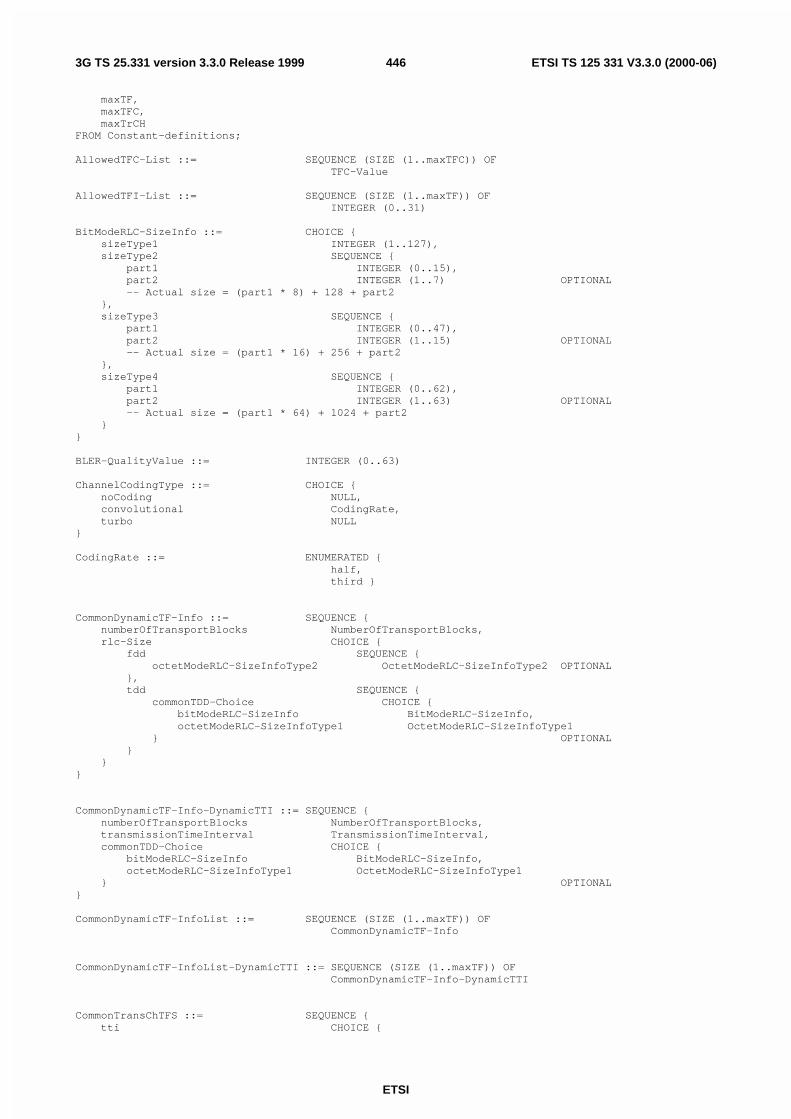
ETSI
ETSI TS 125 331 V3.3.0 (2000-06)4463G TS 25.331 version 3.3.0 Release 1999
maxTF,maxTFC,maxTrCH
FROM Constant-definitions;
AllowedTFC-List ::= SEQUENCE (SIZE (1..maxTFC)) OFTFC-Value
AllowedTFI-List ::= SEQUENCE (SIZE (1..maxTF)) OFINTEGER (0..31)
BitModeRLC-SizeInfo ::= CHOICE {sizeType1 INTEGER (1..127),sizeType2 SEQUENCE {
part1 INTEGER (0..15),part2 INTEGER (1..7) OPTIONAL-- Actual size = (part1 * 8) + 128 + part2
},sizeType3 SEQUENCE {
part1 INTEGER (0..47),part2 INTEGER (1..15) OPTIONAL-- Actual size = (part1 * 16) + 256 + part2
},sizeType4 SEQUENCE {
part1 INTEGER (0..62),part2 INTEGER (1..63) OPTIONAL-- Actual size = (part1 * 64) + 1024 + part2
}}
BLER-QualityValue ::= INTEGER (0..63)
ChannelCodingType ::= CHOICE {noCoding NULL,convolutional CodingRate,turbo NULL
}
CodingRate ::= ENUMERATED {half,third }
CommonDynamicTF-Info ::= SEQUENCE {numberOfTransportBlocks NumberOfTransportBlocks,rlc-Size CHOICE {
fdd SEQUENCE {octetModeRLC-SizeInfoType2 OctetModeRLC-SizeInfoType2 OPTIONAL
},tdd SEQUENCE {
commonTDD-Choice CHOICE {bitModeRLC-SizeInfo BitModeRLC-SizeInfo,octetModeRLC-SizeInfoType1 OctetModeRLC-SizeInfoType1
} OPTIONAL}
}}
CommonDynamicTF-Info-DynamicTTI ::= SEQUENCE {numberOfTransportBlocks NumberOfTransportBlocks,transmissionTimeInterval TransmissionTimeInterval,commonTDD-Choice CHOICE {
bitModeRLC-SizeInfo BitModeRLC-SizeInfo,octetModeRLC-SizeInfoType1 OctetModeRLC-SizeInfoType1
} OPTIONAL}
CommonDynamicTF-InfoList ::= SEQUENCE (SIZE (1..maxTF)) OFCommonDynamicTF-Info
CommonDynamicTF-InfoList-DynamicTTI ::= SEQUENCE (SIZE (1..maxTF)) OFCommonDynamicTF-Info-DynamicTTI
CommonTransChTFS ::= SEQUENCE {tti CHOICE {

ETSI
ETSI TS 125 331 V3.3.0 (2000-06)4473G TS 25.331 version 3.3.0 Release 1999
tti10 CommonDynamicTF-InfoList,tti20 CommonDynamicTF-InfoList,tti40 CommonDynamicTF-InfoList,tti80 CommonDynamicTF-InfoList,dynamic CommonDynamicTF-InfoList-DynamicTTI
},semistaticTF-Information SemistaticTF-Information
}
CPCH-SetID ::= INTEGER (1..maxCPCHsets)
CRC-Size ::= ENUMERATED {crc0, crc8, crc12, crc16, crc24 }
DedicatedDynamicTF-Info ::= SEQUENCE {numberOfTransportBlocks NumberOfTransportBlocks,rlc-Size CHOICE {
bitMode BitModeRLC-SizeInfo,octetModeType1 OctetModeRLC-SizeInfoType1
} OPTIONAL}
DedicatedDynamicTF-Info-DynamicTTI ::= SEQUENCE {numberOfTransportBlocks NumberOfTransportBlocks,transmissionTimeInterval TransmissionTimeInterval,rlc-Size CHOICE {
bitMode BitModeRLC-SizeInfo,octetModeType1 OctetModeRLC-SizeInfoType1
} OPTIONAL}
DedicatedDynamicTF-InfoList ::= SEQUENCE (SIZE (1..maxTF)) OFDedicatedDynamicTF-Info
DedicatedDynamicTF-InfoList-DynamicTTI ::= SEQUENCE (SIZE (1..maxTF)) OFDedicatedDynamicTF-Info-DynamicTTI
DedicatedTransChTFS ::= SEQUENCE {tti CHOICE {
tti10 DedicatedDynamicTF-InfoList,tti20 DedicatedDynamicTF-InfoList,tti40 DedicatedDynamicTF-InfoList,tti80 DedicatedDynamicTF-InfoList,dynamic DedicatedDynamicTF-InfoList-DynamicTTI
},semistaticTF-Information SemistaticTF-Information
}
DL-AddReconfTransChInfo2List ::= SEQUENCE (SIZE (1..maxTrCH)) OFDL-AddReconfTransChInformation2
DL-AddReconfTransChInfoList ::= SEQUENCE (SIZE (1..maxTrCH)) OFDL-AddReconfTransChInformation
DL-AddReconfTransChInformation ::= SEQUENCE {dl-transportChannelIdentity TransportChannelIdentity,tfs-SignallingMode CHOICE {
explicit TransportFormatSet,sameAsULTrCH TransportChannelIdentity
},dch-QualityTarget QualityTarget OPTIONAL,tm-SignallingInfo TM-SignallingInfo OPTIONAL
}
DL-AddReconfTransChInformation2 ::= SEQUENCE {transportChannelIdentity TransportChannelIdentity,tfs-SignallingMode CHOICE {
explicit TransportFormatSet,sameAsULTrCH TransportChannelIdentity
},

ETSI
ETSI TS 125 331 V3.3.0 (2000-06)4483G TS 25.331 version 3.3.0 Release 1999
qualityTarget QualityTarget}
DL-CommonTransChInfo ::= SEQUENCE {sccpch-TFCS TFCS OPTIONAL,modeSpecificInfo CHOICE {
fdd SEQUENCE {tfcs-SignallingMode CHOICE {
explicit TFCS,sameAsUL NULL
} OPTIONAL},tdd SEQUENCE {
individualDL-CCTrCH-InfoList IndividualDL-CCTrCH-InfoListOPTIONAL
}}
}
DL-DeletedTransChInfoList ::= SEQUENCE (SIZE (1..maxTrCH)) OFTransportChannelIdentity
DRAC-ClassIdentity ::= INTEGER (1..maxDRACclasses)
DRAC-StaticInformation ::= SEQUENCE {transmissionTimeValidity TransmissionTimeValidity,timeDurationBeforeRetry TimeDurationBeforeRetry,drac-ClassIdentity DRAC-ClassIdentity
}
DRAC-StaticInformationList ::= SEQUENCE (SIZE (1..maxTrCH)) OFDRAC-StaticInformation
ExplicitTFCS-Configuration ::= CHOICE {complete TFCS-ReconfAdd,addition TFCS-ReconfAdd,removal TFCS-RemovalList,replacement SEQUENCE {
tfcsRemoval TFCS-RemovalList,tfcsAdd TFCS-ReconfAdd
}}
GainFactor ::= INTEGER (0..15)
GainFactorInformation ::= CHOICE {signalledGainFactors SignalledGainFactors,computedGainFactors ReferenceTFC-ID
}
IndividualDL-CCTrCH-Info ::= SEQUENCE {dl-TFCS-Identity TFCS-Identity,tfcs-SignallingMode CHOICE {
explicit TFCS,sameAsUL TFCS-Identity
}}
IndividualDL-CCTrCH-InfoList ::= SEQUENCE (SIZE (1..maxCCTrCH)) OFIndividualDL-CCTrCH-Info
IndividualUL-CCTrCH-Info ::= SEQUENCE {ul-TFCS-Identity TFCS-Identity,ul-TFCS TFCS
}
IndividualUL-CCTrCH-InfoList ::= SEQUENCE (SIZE (1..maxCCTrCH)) OFIndividualUL-CCTrCH-Info
MessType ::= ENUMERATED {transportFormatCombinationControl, spare1 }

ETSI
ETSI TS 125 331 V3.3.0 (2000-06)4493G TS 25.331 version 3.3.0 Release 1999
Non-allowedTFC-List ::= SEQUENCE (SIZE (1..maxTFC)) OFTFC-Value
NumberOfTransportBlocks::= CHOICE {zero NULL,one NULL,small INTEGER (2..17),long INTEGER (18..512)
}
OctetModeRLC-SizeInfoType1 ::= CHOICE {sizeType1 INTEGER (0..31),-- Actual size = (8 * sizeType1) + 16sizeType2 SEQUENCE {
part1 INTEGER (0..23),part2 INTEGER (1..3) OPTIONAL-- Actual size = (32 * part1) + 272 + (part2 * 8)
},sizeType3 SEQUENCE {
part1 INTEGER (0..61),part2 INTEGER (1..7) OPTIONAL-- Actual size = (64 * part1) + 1040 + (part2 * 8)
}}
OctetModeRLC-SizeInfoType2 ::= CHOICE {sizeType1 INTEGER (0..31),-- Actual size = (sizeType1 * 8) + 48sizeType2 INTEGER (0..63),-- Actual size = (sizeType2 * 16) + 312sizeType3 INTEGER (0..56)-- Actual size = (sizeType3 *64) + 1384
}
PowerOffsetInformation ::= SEQUENCE {gainFactorInformation GainFactorInformation,powerOffsetPp-m PowerOffsetPp-m OPTIONAL
}
PowerOffsetPp-m ::= INTEGER (-5..10)
PreDefTransChConfiguration ::= SEQUENCE {ul-CommonTransChInfo UL-CommonTransChInfo,ul-AddReconfTrChInfoList UL-AddReconfTransChInfoList,dl-CommonTransChInfo DL-CommonTransChInfo,dl-TrChInfoList DL-AddReconfTransChInfoList
}
QualityTarget ::= SEQUENCE {bler-QualityValue BLER-QualityValue
}
RateMatchingAttribute ::= INTEGER (1..hiRM)
ReferenceTFC-ID ::= INTEGER (0..3)
RestrictedTrChInfo ::= SEQUENCE {restrictedTrChIdentity TransportChannelIdentity,allowedTFI-List AllowedTFI-List OPTIONAL
}
RestrictedTrChInfoList ::= SEQUENCE (SIZE (1..maxTrCH)) OFRestrictedTrChInfo
SemistaticTF-Information ::= SEQUENCE {-- TABULAR: Transmission time interval has been included in the IE CommonTransChTFS.channelCodingType ChannelCodingType,rateMatchingAttribute RateMatchingAttribute,crc-Size CRC-Size
}

ETSI
ETSI TS 125 331 V3.3.0 (2000-06)4503G TS 25.331 version 3.3.0 Release 1999
SignalledGainFactors ::= SEQUENCE {gainFactorBetaC GainFactor,gainFactorBetaD GainFactor,referenceTFC-ID ReferenceTFC-ID OPTIONAL
}
SplitTFCI-Signalling ::= SEQUENCE {splitType SplitType OPTIONAL,tfci-Field2-Length INTEGER (1..10) OPTIONAL,tfci-Field1-Information ExplicitTFCS-Configuration OPTIONAL,tfci-Field2-Information TFCI-Field2-Information OPTIONAL
}
SplitType ::= ENUMERATED {hardSplit, logicalSplit }
TFC-Subset ::= CHOICE {minimumAllowedTFC-Number TFC-Value,allowedTFC-List AllowedTFC-List,non-allowedTFC-List Non-allowedTFC-List,restrictedTrChInfoList RestrictedTrChInfoList
}
TFC-Value ::= INTEGER (0..1023)
TFCI-Field2-Information ::= CHOICE {tfci-Range TFCI-RangeList,explicit ExplicitTFCS-Configuration
}
TFCI-Range ::= SEQUENCE {maxTFCIField2Value INTEGER (1..1023),tfcs-InfoForDSCH TFCS-InfoForDSCH
}
TFCI-RangeList ::= SEQUENCE (SIZE (1..maxPDSCH-TFCIgroups)) OFTFCI-Range
TFCS ::= CHOICE {normalTFCI-Signalling ExplicitTFCS-Configuration,splitTFCI-Signalling SplitTFCI-Signalling
}
TFCS-Identity ::= SEQUENCE {tfcs-ID INTEGER (1..8) DEFAULT 1,sharedChannelIndicator BOOLEAN
}
TFCS-IdentityPlain ::= INTEGER (1..8)
TFCS-InfoForDSCH ::= CHOICE {ctfc2bit INTEGER (0..3),ctfc4bit INTEGER (0..15),ctfc6bit INTEGER (0..63),ctfc8bit INTEGER (0..255),ctfc12bit INTEGER (0..4095),ctfc16bit INTEGER (0..65535),ctfc24bit INTEGER (0..16777215),spare NULL
}
TFCS-ReconfAdd ::= SEQUENCE{ctfcSize CHOICE{

ETSI
ETSI TS 125 331 V3.3.0 (2000-06)4513G TS 25.331 version 3.3.0 Release 1999
ctfc2Bit SEQUENCE (SIZE (1..maxTFC)) OF SEQUENCE {ctfc2 INTEGER (0..3),gainFactorInformation PowerOffsetInformation OPTIONAL
},ctfc4Bit SEQUENCE (SIZE (1..maxTFC)) OF SEQUENCE {
ctfc4 INTEGER (0..15),gainFactorInformation PowerOffsetInformation OPTIONAL
},ctfc6Bit SEQUENCE (SIZE (1..maxTFC)) OF SEQUENCE {
ctfc8 INTEGER (0..63),gainFactorInformation PowerOffsetInformation OPTIONAL
},ctfc8Bit SEQUENCE (SIZE (1..maxTFC)) OF SEQUENCE {
ctfc16 INTEGER (0..255),gainFactorInformation PowerOffsetInformation OPTIONAL
},ctfc12Bit SEQUENCE (SIZE(1..maxTFC)) OF SEQUENCE {
ctfc12 INTEGER (0..4095), gainFactorInformation PowerOffsetInformation OPTIONAL
},ctfc16Bit SEQUENCE (SIZE (1..maxTFC)) OF SEQUENCE {
ctfc16 INTEGER(0..65535),gainFactorInformation PowerOffsetInformation OPTIONAL
},ctfc24Bit SEQUENCE (SIZE (1..maxTFC)) OF SEQUENCE {
ctfc24 INTEGER(0..16777215),gainFactorInformation PowerOffsetInformation OPTIONAL
},spare NULL
}}
TFCS-Removal ::= SEQUENCE {tfci INTEGER (0..1023)
}
TFCS-RemovalList ::= SEQUENCE (SIZE (1..maxTFC)) OFTFCS-Removal
TimeDurationBeforeRetry ::= INTEGER (1..256)
TM-SignallingInfo ::= SEQUENCE {messType MessType,tm-SignallingMode CHOICE {
mode1 NULL,mode2 SEQUENCE {
ul-controlledTrChList UL-ControlledTrChList}
}}
TransmissionTimeInterval ::= ENUMERATED {tti10, tti20, tti40, tti80,spare1, spare2, spare3, spare4 }
TransmissionTimeValidity ::= INTEGER (1..256)
TransportChannelIdentity ::= INTEGER (1..32)
TransportFormatSet ::= CHOICE {dedicatedTransChTFS DedicatedTransChTFS,commonTransChTFS CommonTransChTFS
}
UL-AddReconfTransChInfoList ::= SEQUENCE (SIZE (1..maxTrCH)) OFUL-AddReconfTransChInformation
UL-AddReconfTransChInformation ::= SEQUENCE {transportChannelIdentity TransportChannelIdentity,transportFormatSet TransportFormatSet
}

ETSI
ETSI TS 125 331 V3.3.0 (2000-06)4523G TS 25.331 version 3.3.0 Release 1999
UL-CommonTransChInfo ::= SEQUENCE {tfc-Subset TFC-Subset OPTIONAL,modeSpecificInfo CHOICE {
fdd SEQUENCE {ul-TFCS TFCS
},tdd SEQUENCE {
individualUL-CCTrCH-InfoList IndividualUL-CCTrCH-InfoListOPTIONAL,
ul-TFCS TFCS}
} OPTIONAL}
UL-ControlledTrChList ::= SEQUENCE (SIZE (1..maxTrCH)) OFTransportChannelIdentity
UL-DeletedTransChInfoList ::= SEQUENCE (SIZE (1..maxTrCH)) OFTransportChannelIdentity
END
11.3.6 Physical channel information elementsPhysicalChannel-IEs DEFINITIONS AUTOMATIC TAGS ::=
BEGIN
IMPORTS
maxASC,maxASCmap,maxASCpersist,maxCCTrCH,maxCPCHsets,maxDPCH-DLchan,maxDPCHcodesPerTS,maxDPDCH-UL,maxFACH,maxPCPCH-APsig,maxPCPCH-APsubCh,maxPCPCH-CDsig,maxPCPCH-CDsubCh,maxPCPCH-SF,maxPCPCHs,maxPDSCH,maxPDSCH-TFCIgroups,maxPRACH,maxPUSCH,maxRL,maxRL-1,maxSCCPCH,maxSig,maxSubCh,maxTF-CPCH,maxTFCI-2-Combs,maxTGPS,maxTS
FROM Constant-definitions
ActivationTimeFROM UserEquipment-IEs
CPCH-SetID,TFCS,TFCS-Identity,TransportChannelIdentity,TransportFormatSet
FROM TransportChannel-IEs
SIB-ReferenceListFACHFROM Other-IEs;
AC-To-ASC-Mapping ::= INTEGER (0..7)

ETSI
ETSI TS 125 331 V3.3.0 (2000-06)4533G TS 25.331 version 3.3.0 Release 1999
AC-To-ASC-MappingTable ::= SEQUENCE (SIZE (maxASCmap)) OFAC-To-ASC-Mapping
AccessServiceClass ::= SEQUENCE {availableSignatureStartIndex INTEGER (0..15),availableSignatureEndIndex INTEGER (0..15),availableSubChannelStartIndex INTEGER (0..11),availableSubChannelEndIndex INTEGER (0..11)
}
AccessServiceClassIndex ::= INTEGER (1..8)
AICH-Info ::= SEQUENCE {secondaryScramblingCode SecondaryScramblingCode OPTIONAL,channelisationCode256 ChannelisationCode256,sttd-Indicator BOOLEAN,aich-TransmissionTiming AICH-TransmissionTiming
}
AICH-PowerOffset ::= INTEGER (-10..5)
AICH-TransmissionTiming ::= ENUMERATED {e0, e1 }
AllocationPeriodInfo ::= SEQUENCE {allocationActivationTime INTEGER (1..256),allocationDuration INTEGER (1..256)
}
AP-AICH-ChannelisationCode ::= INTEGER (0..255)
AP-PreambleScramblingCode ::= INTEGER (0..79)
AP-Signature ::= INTEGER (0..15)
AP-Signature-VCAM ::= SEQUENCE {ap-Signature AP-Signature,availableAP-SubchannelList AvailableAP-SubchannelList OPTIONAL
}
AP-Subchannel ::= INTEGER (0..11)
ASC ::= SEQUENCE {accessServiceClass AccessServiceClassIndex,repetitionPeriodAndOffset ASC-RepetitionPeriodAndOffset OPTIONAL-- TABULAR: The offset is nested in the repetition period
}
ASC-RepetitionPeriodAndOffset ::= CHOICE {rp1 NULL,rp2 INTEGER (0..1),rp4 INTEGER (0..3),rp8 INTEGER (0..7)
}
AvailableAP-Signature-VCAMList ::= SEQUENCE (SIZE (1..maxPCPCH-APsig)) OFAP-Signature-VCAM
AvailableAP-SignatureList ::= SEQUENCE (SIZE (1..maxPCPCH-APsig)) OFAP-Signature
AvailableAP-SubchannelList ::= SEQUENCE (SIZE (1..maxPCPCH-APsubCh)) OFAP-Subchannel
AvailableMinimumSF-ListVCAM ::= SEQUENCE (SIZE (1..maxPCPCH-SF)) OFAvailableMinimumSF-VCAM
AvailableMinimumSF-VCAM ::= SEQUENCE {minimumSpreadingFactor MinimumSpreadingFactor,nf-Max NF-Max,

ETSI
ETSI TS 125 331 V3.3.0 (2000-06)4543G TS 25.331 version 3.3.0 Release 1999
maxAvailablePCPCH-Number MaxAvailablePCPCH-Number,availableAP-Signature-VCAMList AvailableAP-Signature-VCAMList
}
AvailableSignatureList ::= SEQUENCE (SIZE (1..maxSig)) OFSignature
AvailableSubChannelNumber ::= INTEGER (0..11)
AvailableSubChannelNumberList ::= SEQUENCE (SIZE (1..maxSubCh)) OFAvailableSubChannelNumber
BurstType ::= ENUMERATED {short1, long2 }
BurstType1 ::= ENUMERATED { ms4, ms8, ms16 }
BurstType2 ::= ENUMERATED { ms3, ms6 }
CCTrCH-PowerControlInfo ::= SEQUENCE {tfcs-Identity TFCS-Identity OPTIONAL,ul-DPCH-PowerControlInfo UL-DPCH-PowerControlInfo
}
CD-AccessSlotSubchannel ::= INTEGER (0..11)
CD-AccessSlotSubchannelList ::= SEQUENCE (SIZE (1..maxPCPCH-CDsubCh)) OFCD-AccessSlotSubchannel
CD-CA-ICH-ChannelisationCode ::= INTEGER (0..255)
CD-PreambleScramblingCode ::= INTEGER (0..79)
CD-SignatureCode ::= INTEGER (0..15)
CD-SignatureCodeList ::= SEQUENCE (SIZE (1..maxPCPCH-CDsig)) OFCD-SignatureCode
CellParametersID ::= INTEGER (0..127)
ChannelAssignmentActive ::= CHOICE {notActive NULL,isActive AvailableMinimumSF-ListVCAM
}
ChannelisationCode256 ::= INTEGER (0..255)
ChannelReqParamsForUCSM ::= SEQUENCE {availableAP-SignatureList AvailableAP-SignatureList,availableAP-SubchannelList AvailableAP-SubchannelList OPTIONAL
}
ClosedLoopTimingAdjMode ::= ENUMERATED {slot1, slot2 }
CodeNumberDSCH ::= INTEGER (0..255)
CodeRange ::= SEQUENCE {pdsch-CodeMapList PDSCH-CodeMapList,codeNumberStart CodeNumberDSCH,codeNumberStop CodeNumberDSCH
}
CodeWordSet ::= ENUMERATED {longCWS,mediumCWS,shortCWS,ssdtOff }
CommonTimeslotInfo ::= SEQUENCE {-- TABULAR: The IE below is MD, but since it can be encoded in a single-- bit it is not defined as OPTIONAL.secondInterleavingMode SecondInterleavingMode,tfci-Coding TFCI-Coding OPTIONAL,puncturingLimit PuncturingLimit,

ETSI
ETSI TS 125 331 V3.3.0 (2000-06)4553G TS 25.331 version 3.3.0 Release 1999
repetitionPeriodAndLength RepetitionPeriodAndLength OPTIONAL}
CommonTimeslotInfoSCCPCH ::= SEQUENCE {-- TABULAR: The IE below is MD, but since it can be encoded in a single-- bit it is not defined as OPTIONAL.secondInterleavingMode SecondInterleavingMode,tfci-Coding TFCI-Coding OPTIONAL,puncturingLimit PuncturingLimit,repetitionPeriodLengthAndOffset RepetitionPeriodLengthAndOffset OPTIONAL
}
-- Values from -10 to 10 are used in Release 99ConstantValue ::= INTEGER (-10..21)
CPCH-PersistenceLevels ::= SEQUENCE {cpch-SetID CPCH-SetID,dynamicPersistenceLevelTF-List DynamicPersistenceLevelTF-List
}
CPCH-PersistenceLevelsList ::= SEQUENCE (SIZE (1..maxCPCHsets)) OFCPCH-PersistenceLevels
CPCH-SetInfo ::= SEQUENCE {cpch-SetID CPCH-SetID,transportFormatSet TransportFormatSet,tfcs TFCS,ap-PreambleScramblingCode AP-PreambleScramblingCode,ap-AICH-ScramblingCode SecondaryScramblingCode OPTIONAL,ap-AICH-ChannelisationCode AP-AICH-ChannelisationCode,cd-PreambleScramblingCode CD-PreambleScramblingCode,cd-CA-ICH-ScramblingCode SecondaryScramblingCode OPTIONAL,cd-CA-ICH-ChannelisationCode CD-CA-ICH-ChannelisationCode,cd-AccessSlotSubchannelList CD-AccessSlotSubchannelList OPTIONAL,cd-SignatureCodeList CD-SignatureCodeList OPTIONAL,deltaPp-m DeltaPp-m,ul-DPCCH-SlotFormat UL-DPCCH-SlotFormat,n-StartMessage N-StartMessage,n-EOT N-EOT,channelAssignmentActive ChannelAssignmentActive,-- TABULAR: VCAM info has been nested inside ChannelAssignmentActive,-- which in turn is mandatory since it's only a binary choice.cpch-StatusIndicationMode CPCH-StatusIndicationMode,pcpch-ChannelInfoList PCPCH-ChannelInfoList
}
CPCH-SetInfoList ::= SEQUENCE (SIZE (1..maxCPCHsets)) OFCPCH-SetInfo
CPCH-StatusIndicationMode ::= ENUMERATED {pcpch-Availability,pcpch-AvailabilityAndMinAvailableSF }
CSICH-PowerOffset ::= INTEGER (-10..5)
-- Actual value = IE value * 512, only values from 0 to 599 used in Release 99.DefaultDPCH-OffsetValue ::= INTEGER (0..1023)
DeltaPp-m ::= INTEGER (-10..10)
-- Actual value = IE value * 0.1DeltaSIR ::= INTEGER (0..30)
DL-CCTrCh ::= SEQUENCE {tfcs-Identity TFCS-Identity OPTIONAL,timeInfo TimeInfo,commonTimeslotInfo CommonTimeslotInfo OPTIONAL,individualTS-InfoDL-CCTrCHList IndividualTS-InfoDL-CCTrCHList OPTIONAL
}

ETSI
ETSI TS 125 331 V3.3.0 (2000-06)4563G TS 25.331 version 3.3.0 Release 1999
DL-CCTrCh-Post ::= SEQUENCE {timeInfo TimeInfo,commonTimeslotInfo CommonTimeslotInfo,individualTS-InfoDL-CCTrCHList IndividualTS-InfoDL-CCTrCHList
}
DL-CCTrChList ::= SEQUENCE (SIZE (1..maxCCTrCH)) OFDL-CCTrCh
DL-ChannelisationCode ::= SEQUENCE {secondaryScramblingCode SecondaryScramblingCode OPTIONAL,sf-AndCodeNumber SF512-AndCodeNumber,scramblingCodeChange ScramblingCodeChange OPTIONAL
}
DL-ChannelisationCodeList ::= SEQUENCE (SIZE (1..maxDPCH-DLchan)) OFDL-ChannelisationCode
DL-CommonInformation ::= SEQUENCE {dl-DPCH-InfoCommon DL-DPCH-InfoCommon OPTIONAL,defaultDPCH-OffsetValue DefaultDPCH-OffsetValue DEFAULT 0,dpch-CompressedModeInfo DPCH-CompressedModeInfo OPTIONAL,tx-DiversityMode TX-DiversityMode OPTIONAL,ssdt-Information SSDT-Information OPTIONAL
}
DL-CommonInformationPost ::= SEQUENCE {dl-DPCH-InfoCommon DL-DPCH-InfoCommonPost OPTIONAL
}
DL-CommonInformationPredef ::= SEQUENCE {dl-DPCH-InfoCommon DL-DPCH-InfoCommonPredef OPTIONAL,defaultDPCH-OffsetValue DefaultDPCH-OffsetValue OPTIONAL
}
DL-CompressedModeMethod ::= ENUMERATED {puncturing, sf-2,higherLayerScheduling }
DL-DPCH-InfoCommon ::= SEQUENCE {dl-DPCH-PowerControlInfo DL-DPCH-PowerControlInfo OPTIONAL,spreadingFactorAndPilot SF512-AndPilot,-- TABULAR: The number of pilot bits is nested inside the spreading factor.positionFixedOrFlexible PositionFixedOrFlexible,tfci-Existence BOOLEAN
}
DL-DPCH-InfoCommonPost ::= SEQUENCE {dl-DPCH-PowerControlInfo DL-DPCH-PowerControlInfo OPTIONAL
}
DL-DPCH-InfoCommonPredef ::= SEQUENCE {spreadingFactorAndPilot SF512-AndPilot,-- TABULAR: The number of pilot bits is nested inside the spreading factor.positionFixedOrFlexible PositionFixedOrFlexible,tfci-Existence BOOLEAN
}
DL-DPCH-InfoPerRL ::= CHOICE {fdd SEQUENCE {
pCPICH-UsageForChannelEst PCPICH-UsageForChannelEst,dcph-FrameOffset DPCH-FrameOffset,secondaryCPICH-Info SecondaryCPICH-Info OPTIONAL,dl-ChannelisationCodeList DL-ChannelisationCodeList,tpc-CombinationIndex TPC-CombinationIndex,ssdt-CellIdentity SSDT-CellIdentity OPTIONAL,closedLoopTimingAdjMode ClosedLoopTimingAdjMode OPTIONAL
},

ETSI
ETSI TS 125 331 V3.3.0 (2000-06)4573G TS 25.331 version 3.3.0 Release 1999
tdd DL-CCTrChList}
DL-DPCH-InfoPerRL-Post ::= CHOICE {fdd SEQUENCE {
pCPICH-UsageForChannelEst PCPICH-UsageForChannelEst OPTIONAL,dl-ChannelisationCode DL-ChannelisationCode,tpc-CombinationIndex TPC-CombinationIndex
},tdd SEQUENCE {
dl-CCTrCh-Post DL-CCTrCh-Post}
}
DL-DPCH-PowerControlInfo ::= SEQUENCE {-- TABULAR: DPC-Mode is applicable for FDD mode only.dpc-Mode DPC-Mode OPTIONAL
}
DL-FrameType ::= ENUMERATED {dl-FrameTypeA, dl-FrameTypeB }
DL-InformationPerRL ::= SEQUENCE {modeSpecificInfo CHOICE {
fdd SEQUENCE {primaryCPICH-Info PrimaryCPICH-Info,pdsch-SHO-DCH-Info PDSCH-SHO-DCH-Info OPTIONAL,pdsch-CodeMapping PDSCH-CodeMapping OPTIONAL
},tdd PrimaryCCPCH-Info
},dl-DPCH-InfoPerRL DL-DPCH-InfoPerRL OPTIONAL,secondaryCCPCH-Info SecondaryCCPCH-Info OPTIONAL,tfcs TFCS OPTIONAL,fach-PCH-InformationList FACH-PCH-InformationList OPTIONAL,sib-ReferenceList SIB-ReferenceListFACH OPTIONAL
}
DL-InformationPerRL-List ::= SEQUENCE (SIZE (1..maxRL)) OFDL-InformationPerRL
DL-InformationPerRL-ListPost ::= SEQUENCE (SIZE (1..maxRL)) OFDL-InformationPerRL-Post
DL-InformationPerRL-Post ::= SEQUENCE {modeSpecificInfo CHOICE {
fdd SEQUENCE {primaryCPICH-Info PrimaryCPICH-Info
},tdd SEQUENCE {
primaryCCPCH-Info PrimaryCCPCH-Info OPTIONAL}
},dl-DPCH-InfoPerRL DL-DPCH-InfoPerRL-Post
}
DL-OuterLoopControl ::= ENUMERATED {increaseAllowed, increaseNotAllowed }
DL-PDSCH-Information ::= SEQUENCE {pdsch-SHO-DCH-Info PDSCH-SHO-DCH-Info OPTIONAL,pdsch-CodeMapping PDSCH-CodeMapping OPTIONAL
}
DL-TS-ChannelisationCode ::= ENUMERATED {cc16-1, cc16-2, cc16-3, cc16-4,cc16-5, cc16-6, cc16-7, cc16-8,cc16-9, cc16-10, cc16-11, cc16-12,cc16-13, cc16-14, cc16-15, cc16-16 }
DL-TS-ChannelisationCodeList ::= SEQUENCE (SIZE (1..maxDPCHcodesPerTS)) OFDL-TS-ChannelisationCode

ETSI
ETSI TS 125 331 V3.3.0 (2000-06)4583G TS 25.331 version 3.3.0 Release 1999
DPC-Mode ::= ENUMERATED {singleTPC,tpcTripletInSoft }
-- The actual value of DPCCH power offset is the value of this IE * 2.DPCCH-PowerOffset ::= INTEGER (-82..-3)
DPCH-CompressedModeInfo ::= SEQUENCE {tgp-SequenceList TGP-SequenceList
}
DPCH-CompressedModeStatusInfo ::= SEQUENCE (SIZE (1..maxTGPS)) OFTGP-SequenceShort
-- TABULAR: Actual value = IE value * 256DPCH-FrameOffset::= INTEGER (0..149)
DSCH-Mapping ::= SEQUENCE {maxTFCI-Field2Value MaxTFCI-Field2Value,spreadingFactor SF-PDSCH,codeNumber CodeNumberDSCH,multiCodeInfo MultiCodeInfo
}
DSCH-MappingList ::= SEQUENCE (SIZE (1..maxPDSCH-TFCIgroups)) OFDSCH-Mapping
DSCH-RadioLinkIdentifier ::= INTEGER (0..511)
DurationTimeInfo ::= INTEGER (1..4096)
DynamicPersistenceLevel ::= INTEGER (1..8)
DynamicPersistenceLevelList ::= SEQUENCE (SIZE (1..maxPRACH)) OFDynamicPersistenceLevel
DynamicPersistenceLevelTF-List ::= SEQUENCE (SIZE (1..maxTF-CPCH)) OFDynamicPersistenceLevel
FACH-PCH-Information ::= SEQUENCE {transportFormatSet TransportFormatSet,transportChannelIdentity TransportChannelIdentity,ctch-Indicator BOOLEAN
}
FACH-PCH-InformationList ::= SEQUENCE (SIZE (1..maxFACH)) OFFACH-PCH-Information
FrequencyInfo ::= SEQUENCE {modeSpecificInfo CHOICE {
fdd SEQUENCE {uarfcn-UL UARFCN,uarfcn-DL UARFCN OPTIONAL
},tdd SEQUENCE {
uarfcn-Nt UARFCN}
}}
IndividualTimeslotInfo ::= SEQUENCE {timeslotNumber TimeslotNumber,tfci-Existence BOOLEAN OPTIONAL,burstType CHOICE {
type-1 SEQUENCE {midambleShift MidambleShiftLong OPTIONAL
},type-2 SEQUENCE {
midambleShift MidambleShiftShort OPTIONAL

ETSI
ETSI TS 125 331 V3.3.0 (2000-06)4593G TS 25.331 version 3.3.0 Release 1999
}}
}
IndividualTS-InfoDL-CCTrCH ::= SEQUENCE {individualTimeslotInfo IndividualTimeslotInfo,dl-TS-ChannelisationCodeList DL-TS-ChannelisationCodeList
}
IndividualTS-InfoDL-CCTrCHList ::= SEQUENCE (SIZE (1..maxTS)) OFIndividualTS-InfoDL-CCTrCH
IndividualTS-InfoPDSCH ::= SEQUENCE {individualTimeslotInfo IndividualTimeslotInfo,pdsch-ChannelisationCode DL-TS-ChannelisationCodeList
}
IndividualTS-InfoPDSCH-List ::= SEQUENCE (SIZE (1..maxTS)) OFIndividualTS-InfoPDSCH
IndividualTS-InfoPUSCH ::= SEQUENCE {individualTimeslotInfo IndividualTimeslotInfo,ul-ChannelisationCode UL-TS-ChannelisationCodeList
}
IndividualTS-InfoPUSCH-List ::= SEQUENCE (SIZE (1..maxTS)) OFIndividualTS-InfoPUSCH
IndividualTS-InfoUL-CCTrCH ::= SEQUENCE {individualTimeslotInfo IndividualTimeslotInfo,channelisationCodeList UL-TS-ChannelisationCodeList
}
IndividualTS-InfoUL-CCTrCH-List ::= SEQUENCE (SIZE (1..maxTS)) OFIndividualTS-InfoUL-CCTrCH
IndividualTS-Interference ::= SEQUENCE {timeslot TimeslotNumber,ul-TimeslotInterference UL-Interference
}
IndividualTS-InterferenceList ::= SEQUENCE (SIZE (1..maxTS)) OFIndividualTS-Interference
ITP ::= ENUMERATED {mode0, mode1 }
-- Value range of -50..33 is used for Release 99MaxAllowedUL-TX-Power ::= INTEGER (-50..77)
MaxAvailablePCPCH-Number ::= INTEGER (1..64)
MaxTFCI-Field2Value ::= INTEGER (1..1023)
MidambleConfiguration ::= SEQUENCE {burstType1 BurstType1 DEFAULT ms8,-- TABULAR: The default value for BurstType2 has not been specified due to-- compactness reasons.burstType2 BurstType2
}
MidambleShiftLong ::= INTEGER (0..15)
MidambleShiftShort ::= INTEGER (0..5)
MinimumSpreadingFactor ::= ENUMERATED {sf4, sf8, sf16, sf32,sf64, sf128, sf256 }
MultiCodeInfo ::= INTEGER (1..16)

ETSI
ETSI TS 125 331 V3.3.0 (2000-06)4603G TS 25.331 version 3.3.0 Release 1999
N-EOT ::= INTEGER (0..7)
N-GAP ::= ENUMERATED {f2, f4, f8 }
N-PCH ::= INTEGER (1..8)
N-StartMessage ::= INTEGER (1..8)
NB01 ::= INTEGER (0..50)
NF-Max ::= INTEGER (1..64)
NumberOfDPDCH ::= INTEGER (1..maxDPDCH-UL)
NumberOfFBI-Bits ::= INTEGER (1..2)
PagingIndicatorLength ::= ENUMERATED {pi2, pi4, pi8 }
PC-Preamble ::= ENUMERATED {pcp0, pcp15 }
PCP-Length ::= ENUMERATED {as0, as8 }
PCPCH-ChannelInfo ::= SEQUENCE {pcpch-UL-ScramblingCode INTEGER (0..79),pcpch-DL-ChannelisationCode INTEGER (0..511),pcpch-DL-ScramblingCode SecondaryScramblingCode OPTIONAL,pcp-Length PCP-Length,ucsm-Info UCSM-Info OPTIONAL
}
PCPCH-ChannelInfoList ::= SEQUENCE (SIZE (1..maxPCPCHs)) OFPCPCH-ChannelInfo
PCPICH-UsageForChannelEst ::= ENUMERATED {mayBeUsed,shallNotBeUsed }
PDSCH-CodeInfo ::= SEQUENCE {spreadingFactor SF-PDSCH,codeNumber CodeNumberDSCH,multiCodeInfo MultiCodeInfo
}
PDSCH-CodeInfoList ::= SEQUENCE (SIZE (1..maxTFCI-2-Combs)) OFPDSCH-CodeInfo
PDSCH-CodeMap ::= SEQUENCE {spreadingFactor SF-PDSCH,multiCodeInfo MultiCodeInfo
}
PDSCH-CodeMapList ::= SEQUENCE (SIZE (1..maxPDSCH-TFCIgroups)) OFPDSCH-CodeMap
PDSCH-CodeMapping ::= SEQUENCE {dl-ScramblingCode SecondaryScramblingCode OPTIONAL,signallingMethod CHOICE {
codeRange CodeRange,tfci-Range DSCH-MappingList,explicit PDSCH-CodeInfoList,replace ReplacedPDSCH-CodeInfoList
}}
PDSCH-Info ::= SEQUENCE {tfcs-Identity TFCS-Identity OPTIONAL,sfn-TimeInfo SFN-TimeInfo OPTIONAL,

ETSI
ETSI TS 125 331 V3.3.0 (2000-06)4613G TS 25.331 version 3.3.0 Release 1999
commonTimeslotInfo CommonTimeslotInfo OPTIONAL,individualTimeslotInfoList IndividualTS-InfoPDSCH-List OPTIONAL
}
PDSCH-SHO-DCH-Info ::= SEQUENCE {dsch-RadioLinkIdentifier DSCH-RadioLinkIdentifier,tfci-CombiningSet TFCI-CombiningSet OPTIONAL,rl-IdentifierList RL-IdentifierList OPTIONAL
}
PDSCH-SysInfo ::= SEQUENCE {pdsch-Info PDSCH-Info,dsch-TFS TransportFormatSet,dsch-TFCS TFCS
}
PDSCH-SysInfoList ::= SEQUENCE (SIZE (1..maxPDSCH)) OFPDSCH-SysInfo
PersistenceScalingFactor ::= ENUMERATED {psf0-9, psf0-8, psf0-7, psf0-6,psf0-5, psf0-4, psf0-3, psf0-2 }
PersistenceScalingFactorList ::= SEQUENCE (SIZE (1..maxASCpersist)) OFPersistenceScalingFactor
PI-CountPerFrame ::= ENUMERATED {e18, e36, e72, e144 }
PICH-Info ::= CHOICE {fdd SEQUENCE {
secondaryScramblingCode SecondaryScramblingCode OPTIONAL,channelisationCode256 ChannelisationCode256,pi-CountPerFrame PI-CountPerFrame,sttd-Indicator BOOLEAN
},tdd SEQUENCE {
channelisationCode TDD-PICH-CCode OPTIONAL,timeslot TimeslotNumber OPTIONAL,burstType CHOICE {
type-1 MidambleShiftLong,type-2 MidambleShiftShort
} OPTIONAL,repetitionPeriodLengthOffset RepPerLengthOffset-PICH OPTIONAL,pagingIndicatorLength PagingIndicatorLength DEFAULT pi2,n-GAP N-GAP DEFAULT f4,n-PCH N-PCH DEFAULT 2
}}
PICH-PowerOffset ::= INTEGER (-10..5)
PilotBits128 ::= ENUMERATED {pb4, pb8 }
PilotBits256 ::= ENUMERATED {pb2, pb4, pb8 }
PositionFixedOrFlexible ::= ENUMERATED {fixed,flexible }
PowerControlAlgorithm ::= CHOICE {algorithm1 TPC-StepSize,algorithm2 NULL
}
PowerOffsetP0 ::= INTEGER (1..8)
PRACH-Midamble ::= ENUMERATED {direct,direct-Inverted }
PRACH-Partitioning ::= CHOICE {fdd SEQUENCE (SIZE (1..maxASC)) OF
AccessServiceClass,

ETSI
ETSI TS 125 331 V3.3.0 (2000-06)4623G TS 25.331 version 3.3.0 Release 1999
tdd SEQUENCE (SIZE (1..maxASC)) OFASC
}
PRACH-PowerOffset ::= SEQUENCE {powerOffsetP0 PowerOffsetP0,preambleRetransMax PreambleRetransMax
}
PRACH-RACH-Info ::= SEQUENCE {modeSpecificInfo CHOICE {
fdd SEQUENCE {availableSignatureList AvailableSignatureList,availableSF SF-PRACH,scramblingCodeWordNumber ScramblingCodeWordNumber,puncturingLimit PuncturingLimit,availableSubChannelNumberList AvailableSubChannelNumberList
},tdd SEQUENCE {
timeslot TimeslotNumber,channelisationCode TDD-PRACH-CCodeList,prach-Midamble PRACH-Midamble OPTIONAL
}}
}
PRACH-SystemInformation ::= SEQUENCE {prach-RACH-Info PRACH-RACH-Info,transportChannelIdentity TransportChannelIdentity,rach-TransportFormatSet TransportFormatSet OPTIONAL,rach-TFCS TFCS OPTIONAL,prach-Partitioning PRACH-Partitioning OPTIONAL,persistenceScalingFactorList PersistenceScalingFactorList OPTIONAL,ac-To-ASC-MappingTable AC-To-ASC-MappingTable OPTIONAL,modeSpecificInfo CHOICE {
fdd SEQUENCE {primaryCPICH-TX-Power PrimaryCPICH-TX-Power OPTIONAL,constantValue ConstantValue OPTIONAL,prach-PowerOffset PRACH-PowerOffset OPTIONAL,rach-TransmissionParameters RACH-TransmissionParameters OPTIONAL,aich-Info AICH-Info OPTIONAL
},tdd NULL
}}
PRACH-SystemInformationList ::= SEQUENCE (SIZE (1..maxPRACH)) OFPRACH-SystemInformation
PreambleRetransMax ::= INTEGER (1..64)
PreDefPhyChConfiguration ::= SEQUENCE {ul-DPCH-InfoPredef UL-DPCH-InfoPredef,modeSpecificInfo CHOICE {
fdd SEQUENCE {dl-CommonInformationPredef DL-CommonInformationPredef OPTIONAL
},tdd NULL
}}
PrimaryCCPCH-Info ::= CHOICE {fdd SEQUENCE {
tx-DiversityIndicator BOOLEAN},tdd SEQUENCE {
syncCase CHOICE {syncCase1 SEQUENCE {
timeslot TimeslotNumber},syncCase2 SEQUENCE {
timeslotSync2 TimeslotSync2}
} OPTIONAL,

ETSI
ETSI TS 125 331 V3.3.0 (2000-06)4633G TS 25.331 version 3.3.0 Release 1999
cellParametersID CellParametersID OPTIONAL,blockSTTD-Indicator BOOLEAN
}}
PrimaryCCPCH-TX-Power ::= INTEGER (6..43)
PrimaryCPICH-Info ::= SEQUENCE {primaryScramblingCode PrimaryScramblingCode
}
-- Value range -10 .. 50 used for Release 99PrimaryCPICH-TX-Power ::= INTEGER (-10..53)
PrimaryScramblingCode ::= INTEGER (0..511)
PuncturingLimit ::= ENUMERATED {pl0-40, pl0-44, pl0-48, pl0-52, pl0-56,pl0-60, pl0-64, pl0-68, pl0-72, pl0-76,pl0-80, pl0-84, pl0-88, pl0-92, pl0-96, pl1 }
PUSCH-CapacityAllocationInfo ::= SEQUENCE {pusch-Allocation CHOICE {
pusch-AllocationPending NULL,pusch-AllocationAssignment SEQUENCE {
pusch-PowerControlInfo UL-TargetSIR OPTIONAL,pusch-Info PUSCH-Info
}}
}
PUSCH-Info ::= SEQUENCE {tfcs-Identity TFCS-Identity OPTIONAL,sfn-timeInfo SFN-TimeInfo OPTIONAL,commonTimeslotInfo CommonTimeslotInfo OPTIONAL,timeslotInfoList IndividualTS-InfoPUSCH-List OPTIONAL
}
PUSCH-SysInfo ::= SEQUENCE {pusch-Info PUSCH-Info,usch-TFS TransportFormatSet,usch-TFCS TFCS
}
PUSCH-SysInfoList ::= SEQUENCE (SIZE (1..maxPUSCH)) OFPUSCH-SysInfo
RACH-TransmissionParameters ::= SEQUENCE {mmax INTEGER (1..32),nb01Min NB01,nb01Max NB01
}
ReducedScramblingCodeNumber ::= INTEGER (0..8191)
RepetitionPeriodAndLength ::= CHOICE {repetitionPeriod1 NULL,repetitionPeriod2 INTEGER (1..1),-- repetitionPeriod2 could just as well be NULL also.repetitionPeriod4 INTEGER (1..3),repetitionPeriod8 INTEGER (1..7),repetitionPeriod16 INTEGER (1..15),repetitionPeriod32 INTEGER (1..31),repetitionPeriod64 INTEGER (1..63)
}
RepetitionPeriodLengthAndOffset ::= CHOICE {repetitionPeriod1 NULL,repetitionPeriod2 SEQUENCE {
length NULL,

ETSI
ETSI TS 125 331 V3.3.0 (2000-06)4643G TS 25.331 version 3.3.0 Release 1999
offset INTEGER (0..1)},repetitionPeriod4 SEQUENCE {
length INTEGER (1..3),offset INTEGER (0..3)
},repetitionPeriod8 SEQUENCE {
length INTEGER (1..7),offset INTEGER (0..7)
},repetitionPeriod16 SEQUENCE {
length INTEGER (1..15),offset INTEGER (0..15)
},repetitionPeriod32 SEQUENCE {
length INTEGER (1..31),offset INTEGER (0..31)
},repetitionPeriod64 SEQUENCE {
length INTEGER (1..63),offset INTEGER (0..63)
}}
ReplacedPDSCH-CodeInfo ::= SEQUENCE {tfci-Field2 MaxTFCI-Field2Value,spreadingFactor SF-PDSCH,codeNumber CodeNumberDSCH,multiCodeInfo MultiCodeInfo
}
ReplacedPDSCH-CodeInfoList ::= SEQUENCE (SIZE (1..maxTFCI-2-Combs)) OFReplacedPDSCH-CodeInfo
RepPerLengthOffset-PICH ::= CHOICE {rpp4-2 INTEGER (0..3),rpp8-2 INTEGER (0..7),rpp8-4 INTEGER (0..7),rpp16-2 INTEGER (0..15),rpp16-4 INTEGER (0..15),rpp32-2 INTEGER (0..31),rpp32-4 INTEGER (0..31),rpp64-2 INTEGER (0..63),rpp64-4 INTEGER (0..63)
}
RL-AdditionInformation ::= SEQUENCE {primaryCPICH-Info PrimaryCPICH-Info,dl-DPCH-InfoPerRL DL-DPCH-InfoPerRL,tfci-CombiningIndicator BOOLEAN,secondaryCCPCH-Info SecondaryCCPCH-Info OPTIONAL,tfcs TFCS OPTIONAL,fach-PCH-InformationList FACH-PCH-InformationList OPTIONAL,sib-ReferenceListFACH SIB-ReferenceListFACH OPTIONAL
}
RL-AdditionInformationList ::= SEQUENCE (SIZE (1..maxRL-1)) OFRL-AdditionInformation
RL-IdentifierList ::= SEQUENCE (SIZE (1..maxRL)) OFPrimaryCPICH-Info
RL-RemovalInformationList ::= SEQUENCE (SIZE (1..maxRL)) OFPrimaryCPICH-Info
RPP ::= ENUMERATED {mode0, mode1 }
S-Field ::= ENUMERATED {e1bit, e2bits }
SCCPCH-ChannelisationCode ::= ENUMERATED {cc16-1, cc16-2, cc16-3, cc16-4,cc16-5, cc16-6, cc16-7, cc16-8,cc16-9, cc16-10, cc16-11, cc16-12,cc16-13, cc16-14, cc16-15, cc16-16 }

ETSI
ETSI TS 125 331 V3.3.0 (2000-06)4653G TS 25.331 version 3.3.0 Release 1999
SCCPCH-ChannelisationCodeList ::= SEQUENCE (SIZE (1..16)) OFSCCPCH-ChannelisationCode
SCCPCH-SystemInformation ::= SEQUENCE {secondaryCCPCH-Info SecondaryCCPCH-Info,tfcs TFCS OPTIONAL,fach-PCH-InformationList FACH-PCH-InformationList OPTIONAL,pich-Info PICH-Info OPTIONAL
}
SCCPCH-SystemInformationList ::= SEQUENCE (SIZE (1..maxSCCPCH)) OFSCCPCH-SystemInformation
ScramblingCodeChange ::= ENUMERATED {codeChange, noCodeChange }
ScramblingCodeType ::= ENUMERATED {shortSC,longSC }
ScramblingCodeWordNumber ::= INTEGER (0..15)
SecondaryCCPCH-Info ::= SEQUENCE {selectionIndicator SelectionIndicator OPTIONAL,-- The IE above is conditional on the logical channel type.modeSpecificInfo CHOICE {
fdd SEQUENCE {pCPICH-UsageForChannelEst PCPICH-UsageForChannelEst,secondaryCPICH-Info SecondaryCPICH-Info OPTIONAL,secondaryScramblingCode SecondaryScramblingCode OPTIONAL,sttd-Indicator BOOLEAN,sf-AndCodeNumber SF256-AndCodeNumber,pilotSymbolExistence BOOLEAN,tfci-Existence BOOLEAN,positionFixedOrFlexible PositionFixedOrFlexible,timingOffset TimingOffset DEFAULT 0
},tdd SEQUENCE {
-- TABULAR: the offset is included in CommonTimeslotInfoSCCPCHcommonTimeslotInfo CommonTimeslotInfoSCCPCH,individualTimeslotInfo IndividualTimeslotInfo,channelisationCode SCCPCH-ChannelisationCodeList
}}
}
SecondaryCPICH-Info ::= SEQUENCE {secondaryDL-ScramblingCode SecondaryScramblingCode OPTIONAL,channelisationCode ChannelisationCode256
}
-- Value range 1..15 used for Release 99SecondaryScramblingCode ::= INTEGER (1..16)
SecondInterleavingMode ::= ENUMERATED {frameRelated, timeslotRelated }
SelectionIndicator ::= ENUMERATED {on, off }
-- SF256-AndCodeNumber encodes both "Spreading factor" and "Code Number"SF256-AndCodeNumber ::= CHOICE {
sf4 INTEGER (0..3),sf8 INTEGER (0..7),sf16 INTEGER (0..15),sf32 INTEGER (0..31),sf64 INTEGER (0..63),sf128 INTEGER (0..127),sf256 INTEGER (0..255)
}
-- SF512-AndCodeNumber encodes both "Spreading factor" and "Code Number"SF512-AndCodeNumber ::= CHOICE {

ETSI
ETSI TS 125 331 V3.3.0 (2000-06)4663G TS 25.331 version 3.3.0 Release 1999
sf4 INTEGER (0..3),sf8 INTEGER (0..7),sf16 INTEGER (0..15),sf32 INTEGER (0..31),sf64 INTEGER (0..63),sf128 INTEGER (0..127),sf256 INTEGER (0..255),sf512 INTEGER (0..511)
}
-- SF512-AndPilot encodes both "Spreading factor" and "Number of bits for Pilot bits"SF512-AndPilot ::= CHOICE {
sfd4 NULL,sfd8 NULL,sfd16 NULL,sfd32 NULL,sfd64 NULL,sfd128 PilotBits128,sfd256 PilotBits256,sfd512 NULL
}SF-PDSCH ::= ENUMERATED {
sfp4, sfp8, sfp16, sfp32,sfp64, sfp128, sfp256, spare }
SF-PRACH ::= ENUMERATED {sfpr32, sfpr64, sfpr128, sfpr256 }
SFN-TimeInfo ::= SEQUENCE {activationTime INTEGER (0..4094) OPTIONAL,physChDuration DurationTimeInfo OPTIONAL
}
Signature ::= INTEGER (0..15)
SpreadingFactor::= ENUMERATED {sf4, sf8, sf16, sf32,sf64, sf128, sf256 }
SSDT-CellIdentity ::= ENUMERATED {ssdt-id-a, ssdt-id-b, ssdt-id-c,ssdt-id-d, ssdt-id-e, ssdt-id-f,ssdt-id-g, ssdt-id-h }
SSDT-Information ::= SEQUENCE {s-Field S-Field,codeWordSet CodeWordSet
}
TDD-PICH-CCode ::= ENUMERATED {cc16-1, cc16-2, cc16-3, cc16-4,cc16-5, cc16-6, cc16-7, cc16-8,cc16-9, cc16-10, cc16-11, cc16-12,cc16-13, cc16-14, cc16-15, cc16-16 }
TDD-PRACH-CCode8 ::= ENUMERATED {cc8-1, cc8-2, cc8-3, cc8-4,cc8-5, cc8-6, cc8-7, cc8-8 }
TDD-PRACH-CCode16 ::= ENUMERATED {cc16-1, cc16-2, cc16-3, cc16-4,cc16-5, cc16-6, cc16-7, cc16-8,cc16-9, cc16-10, cc16-11, cc16-12,cc16-13, cc16-14, cc16-15, cc16-16 }
TDD-PRACH-CCodeList ::= CHOICE {sf8 SEQUENCE (SIZE (1..8)) OF
TDD-PRACH-CCode8,sf16 SEQUENCE (SIZE (1..8)) OF
TDD-PRACH-CCode16}

ETSI
ETSI TS 125 331 V3.3.0 (2000-06)4673G TS 25.331 version 3.3.0 Release 1999
TFC-ControlDuration ::= ENUMERATED {tfc-cd1, tfc-cd16, tfc-cd24, tfc-cd32,tfc-cd48, tfc-cd64, tfc-cd128,tfc-cd192, tfc-cd256, tfc-cd512,spare1, spare2, spare3, spare4,spare5, spare6, spare7, spare8 }
TFCI-Coding ::= ENUMERATED {tfci-bits-4, tfci-bits-8,tfci-bits-16, tfci-bits-32 }
-- **TODO**, not definedTFCI-CombiningSet ::= SEQUENCE {}
TGCFN ::= INTEGER (0..255)
-- The value 270 represents "undefined" in the tabular description.TGD ::= INTEGER (15..270)
TGL ::= INTEGER (1..14)
TGMP ::= ENUMERATED {tdd-Measurement, fdd-Measurement,gsm-Measurement, otherMP }
TGP-Sequence ::= SEQUENCE {tgpsi TGPSI,tgps-StatusFlag TGPS-StatusFlag,tgps-ConfigurationParams TGPS-ConfigurationParams OPTIONAL
}
TGP-SequenceList ::= SEQUENCE (SIZE (1..maxTGPS)) OFTGP-Sequence
TGP-SequenceShort ::= SEQUENCE {tgpsi TGPSI,tgps-StatusFlag TGPS-StatusFlag
}
TGPL ::= INTEGER (1..144)
-- TABULAR: The value 0 represents "infinity" in the tabular description.TGPRC ::= INTEGER (0..63)
TGPS-ConfigurationParams ::= SEQUENCE {tgmp TGMP,tgprc TGPRC,tgcfn TGCFN,tgsn TGSN,tgl1 TGL,tgl2 TGL OPTIONAL,tgd TGD,tgpl1 TGPL,tgpl2 TGPL OPTIONAL,rpp RPP,itp ITP,ul-DL-Mode UL-DL-Mode,-- TABULAR: Compressed mode method is nested inside UL-DL-Modedl-FrameType DL-FrameType,deltaSIR1 DeltaSIR,deltaSIRAfter1 DeltaSIR,deltaSIR2 DeltaSIR OPTIONAL,deltaSIRAfter2 DeltaSIR OPTIONAL
}
TGPS-StatusFlag ::= ENUMERATED {tgpsActive, tgpsInactive }
TGPSI ::= INTEGER (1..maxTGPS)

ETSI
ETSI TS 125 331 V3.3.0 (2000-06)4683G TS 25.331 version 3.3.0 Release 1999
TGSN ::= INTEGER (0..14)
TimeInfo ::= SEQUENCE {activationTime ActivationTime OPTIONAL,durationTimeInfo DurationTimeInfo OPTIONAL
}
TimeslotList ::= SEQUENCE (SIZE (1..maxTS)) OFTimeslotNumber
TimeslotNumber ::= INTEGER (0..14)
TimeslotSync2 ::= INTEGER (0..6)
-- Actual value = IE value * 256TimingOffset ::= INTEGER (0..149)
TPC-CombinationIndex ::= INTEGER (0..5)
TPC-StepSize ::= INTEGER (0..1)
TX-DiversityMode ::= ENUMERATED {noDiversity,sttd,closedLoopMode1,closedLoopMode2 }
UARFCN ::= INTEGER (0..16383)
UCSM-Info ::= SEQUENCE {minimumSpreadingFactor MinimumSpreadingFactor,nf-Max NF-Max,channelReqParamsForUCSM ChannelReqParamsForUCSM
}
UL-CCTrCH ::= SEQUENCE {tfcs-Identity TFCS-Identity OPTIONAL,timeInfo TimeInfo,commonTimeslotInfo CommonTimeslotInfo OPTIONAL,timeslotInfoList IndividualTS-InfoUL-CCTrCH-List OPTIONAL
}
UL-CCTrCHList ::= SEQUENCE (SIZE (1..maxCCTrCH)) OFUL-CCTrCH
UL-ChannelRequirement ::= CHOICE {ul-DPCH-Info UL-DPCH-Info,prach-RACH-Info PRACH-RACH-Info,spare NULL
}
UL-CompressedModeMethod ::= ENUMERATED {sf-2, noCompressing,higherLayerScheduling }
UL-DL-Mode ::= CHOICE {ul UL-CompressedModeMethod,dl DL-CompressedModeMethod
}
UL-DPCCH-SlotFormat ::= ENUMERATED {slf0, slf1, slf2 }
UL-DPCH-Info ::= SEQUENCE {ul-DPCH-PowerControlInfo UL-DPCH-PowerControlInfo OPTIONAL,modeSpecificInfo CHOICE {
fdd SEQUENCE {scramblingCodeType ScramblingCodeType,scramblingCode UL-ScramblingCode,numberOfDPDCH NumberOfDPDCH DEFAULT 1,spreadingFactor SpreadingFactor,tfci-Existence BOOLEAN,

ETSI
ETSI TS 125 331 V3.3.0 (2000-06)4693G TS 25.331 version 3.3.0 Release 1999
numberOfFBI-Bits NumberOfFBI-Bits OPTIONAL,-- The IE above is conditional based on historypuncturingLimit PuncturingLimit
},tdd SEQUENCE {
ul-TimingAdvance UL-TimingAdvance OPTIONAL,ul-CCTrCHList UL-CCTrCHList
}}
}
UL-DPCH-InfoPost ::= SEQUENCE {ul-DPCH-PowerControlInfo UL-DPCH-PowerControlInfoPost,modeSpecificInfo CHOICE {
fdd SEQUENCE {scramblingCodeType ScramblingCodeType,reducedScramblingCodeNumber ReducedScramblingCodeNumber,spreadingFactor SpreadingFactor
},tdd SEQUENCE {
ul-TimingAdvance UL-TimingAdvance OPTIONAL,timeInfo TimeInfo,commonTimeslotInfo CommonTimeslotInfo,timeslotInfoList IndividualTS-InfoUL-CCTrCH-List
}}
}
UL-DPCH-InfoPredef ::= SEQUENCE {ul-DPCH-PowerControlInfo UL-DPCH-PowerControlInfoPredef,modeSpecificInfo CHOICE {
fdd SEQUENCE {tfci-Existence BOOLEAN,puncturingLimit PuncturingLimit
},tdd NULL
}}
UL-DPCH-PowerControlInfo ::= CHOICE {fdd SEQUENCE {
dpcch-PowerOffset DPCCH-PowerOffset,pc-Preamble PC-Preamble,powerControlAlgorithm PowerControlAlgorithm-- TABULAR: TPC step size nested inside PowerControlAlgorithm
},tdd SEQUENCE {
ul-TargetSIR UL-TargetSIR,handoverGroup SEQUENCE {
individualTS-InterferenceList IndividualTS-InterferenceList,dpch-ConstantValue ConstantValue
} OPTIONAL}
}
UL-DPCH-PowerControlInfoPost ::= SEQUENCE {modeSpecificInfo CHOICE {
fdd SEQUENCE {powerControlAlgorithm PowerControlAlgorithm-- TABULAR: TPC step size nested inside PowerControlAlgorithm
},tdd SEQUENCE {
ul-TargetSIR UL-TargetSIR,individualTS-InterferenceList IndividualTS-InterferenceList
}}
}
UL-DPCH-PowerControlInfoPredef ::= CHOICE {fdd SEQUENCE {
dpcch-PowerOffset DPCCH-PowerOffset,pc-Preamble PC-Preamble
},

ETSI
ETSI TS 125 331 V3.3.0 (2000-06)4703G TS 25.331 version 3.3.0 Release 1999
tdd SEQUENCE {dpch-ConstantValue ConstantValue
}}
-- Value range -110 .. -70 used for Release 99UL-Interference ::= INTEGER (-110..-47)
--UL-ScramblingCode ::= INTEGER (0..16777215)
-- Actual value = (IE value * 0.5) - 11UL-TargetSIR ::= INTEGER (0..62)
UL-TimingAdvance ::= INTEGER (0..63)
UL-TS-ChannelisationCode ::= ENUMERATED {cc1-1, cc2-1, cc2-2,cc4-1, cc4-2, cc4-3, cc4-4,cc8-1, cc8-2, cc8-3, cc8-4,cc8-5, cc8-6, cc8-7, cc8-8,cc16-1, cc16-2, cc16-3, cc16-4,cc16-5, cc16-6, cc16-7, cc16-8,cc16-9, cc16-10, cc16-11, cc16-12,cc16-13, cc16-14, cc16-15, cc16-16 }
UL-TS-ChannelisationCodeList ::= SEQUENCE (SIZE (1..2)) OFUL-TS-ChannelisationCode
END
11.3.7 Measurement information elementsMeasurement-IEs DEFINITIONS AUTOMATIC TAGS ::=
BEGIN
IMPORTS
CellIdentityFROM UTRANMobility-IEs
UTRAN-DRX-CycleLengthCoefficientFROM UserEquipment-IEs
RB-IdentityFROM RadioBearer-IEs
TFCS-IdentityPlain,TransportChannelIdentity
FROM TransportChannel-IEs
BurstType,FrequencyInfo,MaxAllowedUL-TX-Power,PrimaryCCPCH-Info,PrimaryCCPCH-TX-Power,PrimaryCPICH-Info,PrimaryCPICH-TX-Power,TimeslotNumber,UL-TimingAdvance
FROM PhysicalChannel-IEs
BSICFROM Other-IEs
maxAdditionalMeas,maxCCTrCH,maxCellMeas,maxCellMeas-1,maxFreq,maxMeasEvent,maxMeasParEvent,
• maxOtherRAT,maxRB,maxRL,maxRL-1,maxSat,

ETSI
ETSI TS 125 331 V3.3.0 (2000-06)4713G TS 25.331 version 3.3.0 Release 1999
maxTrCH,maxTS
FROM Constant-definitions;
AcquisitionSatInfo ::= SEQUENCE {satID INTEGER (0..63),doppler0thOrder INTEGER (-2048..2047),extraDopplerInfo ExtraDopplerInfo OPTIONAL,codePhase INTEGER (0..1022),integerCodePhase INTEGER (0..19),gps-BitNumber INTEGER (0..3),codePhaseSearchWindow CodePhaseSearchWindow,azimuthAndElevation AzimuthAndElevation OPTIONAL
}
AcquisitionSatInfoList ::= SEQUENCE (SIZE (1..maxSat)) OFAcquisitionSatInfo
AdditionalAssistanceData ::= OCTET STRING (SIZE (1..38))
AdditionalMeasurementID-List ::= SEQUENCE (SIZE (1..maxAdditionalMeas)) OFMeasurementIdentityNumber
AlmanacSatInfo ::= SEQUENCE {satID INTEGER (0..63),e BIT STRING (SIZE (16)),t-oa BIT STRING (SIZE (8)),deltaI BIT STRING (SIZE (16)),omegaDot BIT STRING (SIZE (16)),satHealth BIT STRING (SIZE (8)),a-Sqrt BIT STRING (SIZE (24)),omega0 BIT STRING (SIZE (24)),m0 BIT STRING (SIZE (24)),omega BIT STRING (SIZE (24)),af0 BIT STRING (SIZE (11)),af1 BIT STRING (SIZE (11))
}
AlmanacSatInfoList ::= SEQUENCE (SIZE (1..maxSat)) OFAlmanacSatInfo
AverageRLC-BufferPayload ::= ENUMERATED {pla0, pla4, pla8, pla16, pla32,pla64, pla128, pla256, pla512,pla1024, pla2k, pla4k, pla8k, pla16k,pla32k, pla64k, pla128k, pla256k,pla512k, pla1024k }
AzimuthAndElevation ::= SEQUENCE {azimuth INTEGER (0..31),elevation INTEGER (0..7)
}
BadSatList ::= SEQUENCE (SIZE (1..maxSat)) OFINTEGER (0..63)
BCCH-ARFCN ::= INTEGER (0..1023)
BLER-MeasurementResults ::= SEQUENCE {transportChannelIdentity TransportChannelIdentity,dl-TransportChannelBLER DL-TransportChannelBLER OPTIONAL
}
BLER-MeasurementResultsList ::= SEQUENCE (SIZE (1..maxTrCH)) OFBLER-MeasurementResults
BLER-TransChIdList ::= SEQUENCE (SIZE (1..maxTrCH)) OFTransportChannelIdentity
BSIC-VerificationRequired ::= ENUMERATED {required, notRequired }
BurstModeParameters ::= SEQUENCE {burstStart INTEGER (0..15),burstLength INTEGER (10..25),

ETSI
ETSI TS 125 331 V3.3.0 (2000-06)4723G TS 25.331 version 3.3.0 Release 1999
burstFreq INTEGER (1..16)}
CellDCH-ReportCriteria ::= CHOICE {intraFreqReportingCriteria IntraFreqReportingCriteria,periodicalReportingCriteria PeriodicalReportingCriteria
}
-- Actual value = IE value * 0.5CellIndividualOffset ::= INTEGER (-20..20)
CellInfo ::= SEQUENCE {cellIndividualOffset CellIndividualOffset DEFAULT 0,referenceTimeDifferenceToCell ReferenceTimeDifferenceToCell OPTIONAL,modeSpecificInfo CHOICE {
fdd SEQUENCE {primaryCPICH-Info PrimaryCPICH-Info OPTIONAL,primaryCPICH-TX-Power PrimaryCPICH-TX-Power OPTIONAL,readSFN-Indicator BOOLEAN,tx-DiversityIndicator BOOLEAN
},tdd SEQUENCE {
primaryCCPCH-Info PrimaryCCPCH-Info,primaryCCPCH-TX-Power PrimaryCCPCH-TX-Power OPTIONAL,timeslotInfoList TimeslotInfoList OPTIONAL
}}
}
CellInfoSI ::= SEQUENCE {cellIndividualOffset CellIndividualOffset DEFAULT 0,referenceTimeDifferenceToCell ReferenceTimeDifferenceToCell OPTIONAL,modeSpecificInfo CHOICE {
fdd SEQUENCE {primaryCPICH-Info PrimaryCPICH-Info OPTIONAL,primaryCPICH-TX-Power PrimaryCPICH-TX-Power OPTIONAL,readSFN-Indicator BOOLEAN,tx-DiversityIndicator BOOLEAN
},tdd SEQUENCE {
primaryCCPCH-Info PrimaryCCPCH-Info,primaryCCPCH-TX-Power PrimaryCCPCH-TX-Power OPTIONAL,timeslotInfoList TimeslotInfoList OPTIONAL
}},cellSelectionReselectionInfo CellSelectReselectInfoSIB-11-12 OPTIONAL
}
CellMeasuredResults ::= SEQUENCE {cellIdentity CellIdentity OPTIONAL,sfn-SFN-ObsTimeDifference SFN-SFN-ObsTimeDifference OPTIONAL,cfn-SFN-ObsTimeDifference CFN-SFN-ObsTimeDifference OPTIONAL,modeSpecificInfo CHOICE {
fdd SEQUENCE {primaryCPICH-Info PrimaryCPICH-Info,cpich-Ec-N0 CPICH-Ec-N0 OPTIONAL,cpich-RSCP CPICH-RSCP OPTIONAL,pathloss Pathloss OPTIONAL
},tdd SEQUENCE {
primaryCCPCH-Info PrimaryCCPCH-Info,primaryCCPCH-RSCP PrimaryCCPCH-RSCP OPTIONAL,timeslotISCP-List TimeslotISCP-List OPTIONAL
}}
}
CellMeasurementEventResults ::= CHOICE {fdd SEQUENCE (SIZE (1..maxCellMeas)) OF
PrimaryCPICH-Info,tdd SEQUENCE (SIZE (1..maxCellMeas)) OF
PrimaryCCPCH-Info}

ETSI
ETSI TS 125 331 V3.3.0 (2000-06)4733G TS 25.331 version 3.3.0 Release 1999
CellPosition ::= SEQUENCE {relativeNorth INTEGER (-32767..32767),relativeEast INTEGER (-32767..32767),relativeAltitude INTEGER (-4095..4095)
}
CellReportingQuantities ::= SEQUENCE {sfn-SFN-OTD-Type SFN-SFN-OTD-Type,cellIdentity BOOLEAN,cfn-SFN-ObsTimeDifference BOOLEAN,modeSpecificInfo CHOICE {
fdd SEQUENCE {cpich-Ec-N0 BOOLEAN,cpich-RSCP BOOLEAN,pathloss BOOLEAN
},tdd SEQUENCE {
timeslotISCP BOOLEAN,primaryCCPCH-RSCP BOOLEAN,pathloss BOOLEAN
}}
}
CellSelectReselectInfoSIB-11-12 ::= SEQUENCE {q-OffsetS-N Q-OffsetS-N DEFAULT 0,maxAllowedUL-TX-Power MaxAllowedUL-TX-Power OPTIONAL,hcs-NeighbouringCellInformation HCS-NeighbouringCellInformation OPTIONAL,modeSpecificInfo CHOICE {
fdd SEQUENCE {q-QualMin Q-QualMin OPTIONAL,q-RxlevMin Q-RxlevMin OPTIONAL
},tdd SEQUENCE {
q-RxlevMin Q-RxlevMin OPTIONAL}
}}
CellToMeasure ::= SEQUENCE {sfn-sfn-Drift INTEGER (0..30) OPTIONAL,primaryCPICH-Info PrimaryCPICH-Info,frequencyInfo FrequencyInfo OPTIONAL,sfn-SFN-ObservedTimeDifference SFN-SFN-ObsTimeDifference1,fineSFN-SFN FineSFN-SFN,cellPosition CellPosition OPTIONAL
}
CellToMeasureInfoList ::= SEQUENCE (SIZE (1..maxCellMeas)) OFCellToMeasure
CellToReport ::= SEQUENCE {frequency Frequency,bsic BSIC
}
CellToReportList ::= SEQUENCE (SIZE (1..maxCellMeas)) OFCellToReport
CFN-SFN-ObsTimeDifference ::= CHOICE {fdd-ChipDiff INTEGER (0..157286399),tdd-FrameDiff INTEGER (0..4095)
}
CodePhaseSearchWindow ::= ENUMERATED {w1023, w1, w2, w3, w4, w6, w8,w12, w16, w24, w32, w48, w64,w96, w128, w192 }
CPICH-Ec-N0 ::= INTEGER (-20..0)
-- IE value 0 = <-24 dB, 1 = between -24 and -23 and so onCPICH-Ec-N0-OTDOA ::= INTEGER (0..26)

ETSI
ETSI TS 125 331 V3.3.0 (2000-06)4743G TS 25.331 version 3.3.0 Release 1999
CPICH-RSCP ::= INTEGER (-115..-40)
DeltaPRC ::= INTEGER (-127..127)
DeltaRRC ::= INTEGER (-7..7)
DGPS-CorrectionSatInfo ::= SEQUENCE {satID INTEGER (0..63),iode BIT STRING (SIZE (8)),udre UDRE,prc PRC,rrc RRC,deltaPRC2 DeltaPRC,deltaRRC2 DeltaRRC,deltaPRC3 DeltaPRC,deltaRRC3 DeltaRRC
}
DGPS-CorrectionSatInfoList ::= SEQUENCE (SIZE (1..maxSat)) OFDGPS-CorrectionSatInfo
DGPS-Information ::= SEQUENCE {satID SatID,iode IODE,udre UDRE,prc PRC,rrc RRC,deltaPRC2 DeltaPRC,deltaRRC2 DeltaRRC
}
DGPS-InformationList ::= SEQUENCE (SIZE (1..maxSat)) OFDGPS-Information
DiffCorrectionStatus ::= ENUMERATED {udre-1-0, udre-0-75, udre-0-5, udre-0-3,udre-0-2, udre-0-1, noData, invalidData }
-- Actual value = IE value * 0.02DL-PhysicalChannelBER ::= INTEGER (0..255)
-- Actual value = IE value * 0.02DL-TransportChannelBLER ::= INTEGER (0..255)
DopplerUncertainty ::= ENUMERATED {hz12-5, hz25, hz50, hz100, hz200 }
EllipsoidPoint ::= OCTET STRING (SIZE (7))
EllipsoidPointAltitude ::= OCTET STRING (SIZE (9))
EllipsoidPointAltitudeEllipse ::= OCTET STRING (SIZE (14))
EllipsoidPointUncertCircle ::= OCTET STRING (SIZE (8))
EllipsoidPointUncertEllipse ::= OCTET STRING (SIZE (11))
EnvironmentCharacterization ::= ENUMERATED {possibleHeavyMultipathNLOS,lightMultipathLOS,notDefined }
Event1a ::= SEQUENCE {triggeringCondition TriggeringCondition,reportingRange ReportingRange,forbiddenAffectCellList ForbiddenAffectCellList OPTIONAL,w W,reportDeactivationThreshold ReportDeactivationThreshold
}
Event1b ::= SEQUENCE {triggeringCondition TriggeringCondition,reportingRange ReportingRange,forbiddenAffectCellList ForbiddenAffectCellList OPTIONAL,
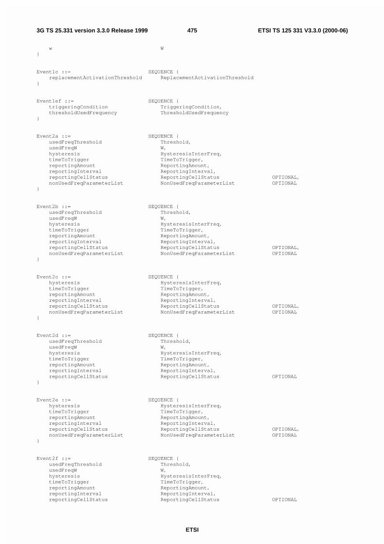
ETSI
ETSI TS 125 331 V3.3.0 (2000-06)4753G TS 25.331 version 3.3.0 Release 1999
w W}
Event1c ::= SEQUENCE {replacementActivationThreshold ReplacementActivationThreshold
}
Event1ef ::= SEQUENCE {triggeringCondition TriggeringCondition,thresholdUsedFrequency ThresholdUsedFrequency
}
Event2a ::= SEQUENCE {usedFreqThreshold Threshold,usedFreqW W,hysteresis HysteresisInterFreq,timeToTrigger TimeToTrigger,reportingAmount ReportingAmount,reportingInterval ReportingInterval,reportingCellStatus ReportingCellStatus OPTIONAL,nonUsedFreqParameterList NonUsedFreqParameterList OPTIONAL
}
Event2b ::= SEQUENCE {usedFreqThreshold Threshold,usedFreqW W,hysteresis HysteresisInterFreq,timeToTrigger TimeToTrigger,reportingAmount ReportingAmount,reportingInterval ReportingInterval,reportingCellStatus ReportingCellStatus OPTIONAL,nonUsedFreqParameterList NonUsedFreqParameterList OPTIONAL
}
Event2c ::= SEQUENCE {hysteresis HysteresisInterFreq,timeToTrigger TimeToTrigger,reportingAmount ReportingAmount,reportingInterval ReportingInterval,reportingCellStatus ReportingCellStatus OPTIONAL,nonUsedFreqParameterList NonUsedFreqParameterList OPTIONAL
}
Event2d ::= SEQUENCE {usedFreqThreshold Threshold,usedFreqW W,hysteresis HysteresisInterFreq,timeToTrigger TimeToTrigger,reportingAmount ReportingAmount,reportingInterval ReportingInterval,reportingCellStatus ReportingCellStatus OPTIONAL
}
Event2e ::= SEQUENCE {hysteresis HysteresisInterFreq,timeToTrigger TimeToTrigger,reportingAmount ReportingAmount,reportingInterval ReportingInterval,reportingCellStatus ReportingCellStatus OPTIONAL,nonUsedFreqParameterList NonUsedFreqParameterList OPTIONAL
}
Event2f ::= SEQUENCE {usedFreqThreshold Threshold,usedFreqW W,hysteresis HysteresisInterFreq,timeToTrigger TimeToTrigger,reportingAmount ReportingAmount,reportingInterval ReportingInterval,reportingCellStatus ReportingCellStatus OPTIONAL

ETSI
ETSI TS 125 331 V3.3.0 (2000-06)4763G TS 25.331 version 3.3.0 Release 1999
}
Event3a ::= SEQUENCE {thresholdOwnSystem Threshold,w W,thresholdOtherSystem Threshold,hysteresis Hysteresis,timeToTrigger TimeToTrigger,reportingAmount ReportingAmount,reportingInterval ReportingInterval,reportingCellStatus ReportingCellStatus OPTIONAL
}
Event3b ::= SEQUENCE {thresholdOtherSystem Threshold,hysteresis Hysteresis,timeToTrigger TimeToTrigger,reportingAmount ReportingAmount,reportingInterval ReportingInterval,reportingCellStatus ReportingCellStatus OPTIONAL
}
Event3c ::= SEQUENCE {thresholdOtherSystem Threshold,hysteresis Hysteresis,timeToTrigger TimeToTrigger,reportingAmount ReportingAmount,reportingInterval ReportingInterval,reportingCellStatus ReportingCellStatus OPTIONAL
}
Event3d ::= SEQUENCE {hysteresis Hysteresis,timeToTrigger TimeToTrigger,reportingAmount ReportingAmount,reportingInterval ReportingInterval,reportingCellStatus ReportingCellStatus OPTIONAL
}
EventIDInterFreq ::= ENUMERATED {e2a, e2b, e2c, e2d, e2e, e2f }
EventIDInterSystem ::= ENUMERATED {e3a, e3b, e3c, e3d }
EventIDIntraFreq ::= ENUMERATED {e1a, e1b, e1c, e1d, e1e,e1f, e1g, e1h, e1i }
EventResults ::= CHOICE {intraFreqEventResults IntraFreqEventResults,interFreqEventResults InterFreqEventResults,interSystemEventResults InterSystemEventResults,trafficVolumeEventResults TrafficVolumeEventResults,qualityEventResults QualityEventResults,ue-InternalEventResults UE-InternalEventResults,lcs-MeasurementEventResults LCS-MeasurementEventResults
}
ExtraDopplerInfo ::= SEQUENCE {doppler1stOrder INTEGER (-42..21),dopplerUncertainty DopplerUncertainty
}
FACH-MeasurementOccasionInfo ::= SEQUENCE {k-UTRA UTRAN-DRX-CycleLengthCoefficient,otherRAT-InSysInfoList OtherRAT-InSysInfoList OPTIONAL
}

ETSI
ETSI TS 125 331 V3.3.0 (2000-06)4773G TS 25.331 version 3.3.0 Release 1999
FilterCoefficient ::= ENUMERATED {fc0, fc1, fc2, fc3, fc4, fc5,fc6, fc7, fc8, fc9, fc11, fc13,fc15, fc17, fc19, spare1 }
FineSFN-SFN ::= ENUMERATED {fs0, fs0-25, fs0-5, fs0-75 }
ForbiddenAffectCell ::= CHOICE {fdd PrimaryCPICH-Info,tdd PrimaryCCPCH-Info
}
ForbiddenAffectCellList ::= SEQUENCE (SIZE (1..maxCellMeas)) OFForbiddenAffectCell
FreqQualityEstimateQuantity-FDD ::= ENUMERATED {cpich-Ec-N0,cpich-RSCP }
FreqQualityEstimateQuantity-TDD ::= ENUMERATED {primaryCCPCH-RSCP }
-- **TODO**, not defined yetFrequency ::= SEQUENCE {}
GSM-CarrierRSSI ::= BIT STRING (SIZE (6))
GPS-MeasurementParam ::= SEQUENCE {satelliteID INTEGER (0..63),c-N0 INTEGER (0..63),doppler INTEGER (-32768..32768),wholeGPS-Chips INTEGER (0..1023),fractionalGPS-Chips INTEGER (0..1023),multipathIndicator MultipathIndicator,pseudorangeRMS-Error INTEGER (0..63)
}
GPS-MeasurementParamList ::= SEQUENCE (SIZE (1..maxSat)) OFGPS-MeasurementParam
-- **TODO**, not defined yetGSM-OutputPower ::= SEQUENCE {}
GPS-TOW-1msec ::= INTEGER (0..604799999)
GPS-TOW-1usec ::= SEQUENCE {tow-1msec GPS-TOW-1msec,tow-rem-usec GPS-TOW-rem-usec
}
GPS-TOW-Assist ::= SEQUENCE {satID INTEGER (0..63),tlm-Message BIT STRING (SIZE (14)),antiSpoof BOOLEAN,alert BOOLEAN,tlm-Reserved BIT STRING (SIZE (2))
}
GPS-TOW-AssistList ::= SEQUENCE (SIZE (1..maxSat)) OFGPS-TOW-Assist
GPS-TOW-rem-usec ::= INTEGER (0..999)
HCS-CellReselectInformation ::= SEQUENCE {penaltyTime PenaltyTime OPTIONAL-- TABULAR: The default value is "notUsed", temporary offset is nested inside PenaltyTime
}
HCS-NeighbouringCellInformation ::= SEQUENCE {hcs-PRIO HCS-PRIO DEFAULT 0,q-HCS Q-HCS DEFAULT 0,

ETSI
ETSI TS 125 331 V3.3.0 (2000-06)4783G TS 25.331 version 3.3.0 Release 1999
hcs-CellReselectInformation HCS-CellReselectInformation OPTIONAL}
HCS-PRIO ::= INTEGER (0..7)
HCS-ServingCellInformation ::= SEQUENCE {hcs-PRIO HCS-PRIO DEFAULT 0,q-HCS Q-HCS DEFAULT 0,t-CR-Max T-CRMax OPTIONAL
}
-- Actual value = IE value * 0.5Hysteresis ::= INTEGER (0..15)
-- Actual value = IE value * 0.5HysteresisInterFreq ::= INTEGER (0..29)
InterFreqCell ::= SEQUENCE {frequencyInfo FrequencyInfo,nonFreqRelatedEventResults CellMeasurementEventResults
}
InterFreqCellID ::= INTEGER (0..maxCellMeas-1)•InterFreqCellInfoList ::= SEQUENCE {
removedInterFreqCellList RemovedInterFreqCellList OPTIONAL,newInterFreqCellList NewInterFreqCellList OPTIONAL
}
InterFreqCellInfoSI-List ::= SEQUENCE {removedInterFreqCellList RemovedInterFreqCellList OPTIONAL,newInterFreqCellList NewInterFreqCellSI-List OPTIONAL
}
InterFreqCellList ::= SEQUENCE (SIZE (1..maxFreq)) OFInterFreqCell
InterFreqCellMeasuredResultsList ::= SEQUENCE (SIZE (1..maxCellMeas)) OFCellMeasuredResults
InterFreqEvent ::= CHOICE {event2a Event2a,event2b Event2b,event2c Event2c,event2d Event2d,event2e Event2e,event2f Event2f
}
InterFreqEventList ::= SEQUENCE (SIZE (1..maxMeasEvent)) OFInterFreqEvent
InterFreqEventResults ::= SEQUENCE {eventID EventIDInterFreq,interFreqCellList InterFreqCellList OPTIONAL
}
InterFreqMeasQuantity ::= SEQUENCE {reportingCriteria CHOICE {
intraFreqReportingCriteria SEQUENCE {intraFreqMeasQuantity IntraFreqMeasQuantity
},interFreqReportingCriteria SEQUENCE {
filterCoefficient FilterCoefficient DEFAULT fc0,modeSpecificInfo CHOICE {
fdd SEQUENCE {freqQualityEstimateQuantity-FDD FreqQualityEstimateQuantity-FDD
},tdd SEQUENCE {
freqQualityEstimateQuantity-TDD FreqQualityEstimateQuantity-TDD}
}}
}}

ETSI
ETSI TS 125 331 V3.3.0 (2000-06)4793G TS 25.331 version 3.3.0 Release 1999
InterFreqMeasuredResults ::= SEQUENCE {frequencyInfo FrequencyInfo OPTIONAL,utra-CarrierRSSI UTRA-CarrierRSSI OPTIONAL,interFreqCellMeasuredResultsList InterFreqCellMeasuredResultsList OPTIONAL
}
InterFreqMeasuredResultsList ::= SEQUENCE (SIZE (1..maxFreq)) OFInterFreqMeasuredResults
InterFreqMeasurementSysInfo ::= SEQUENCE {interFreqMeasurementID MeasurementIdentityNumber DEFAULT 2,interFreqCellInfoSI-List InterFreqCellInfoSI-List OPTIONAL,interFreqMeasQuantity InterFreqMeasQuantity OPTIONAL,interFreqReportingCriteria InterFreqReportingCriteria OPTIONAL
}
InterFreqReportCriteria ::= CHOICE {intraFreqReportingCriteria IntraFreqReportingCriteria,interFreqReportingCriteria InterFreqReportingCriteria,periodicalReportingCriteria PeriodicalWithReportingCellStatus,noReporting ReportingCellStatusOpt
}
InterFreqReportingCriteria ::= SEQUENCE {interFreqEventList InterFreqEventList OPTIONAL
}
InterFreqReportingQuantity ::= SEQUENCE {utra-Carrier-RSSI BOOLEAN,frequencyQualityEstimate BOOLEAN,nonFreqRelatedQuantities CellReportingQuantities
}
InterFrequencyMeasurement ::= SEQUENCE {interFreqCellInfoList InterFreqCellInfoList,interFreqMeasQuantity InterFreqMeasQuantity OPTIONAL,interFreqReportingQuantity InterFreqReportingQuantity OPTIONAL,measurementValidity MeasurementValidity OPTIONAL,interFreqSetUpdate UE-AutonomousUpdateMode OPTIONAL,reportCriteria InterFreqReportCriteria
}
InterSystemCellID ::= INTEGER (0..maxCellMeas-1)
InterSystemCellInfoList ::= SEQUENCE {removedInterSystemCellList RemovedInterSystemCellList,newInterSystemCellList NewInterSystemCellList
}
InterSystemEvent ::= CHOICE {event3a Event3a,event3b Event3b,event3c Event3c,event3d Event3d
}
InterSystemEventList ::= SEQUENCE (SIZE (1..maxMeasEvent)) OFInterSystemEvent
InterSystemEventResults ::= SEQUENCE {eventID EventIDInterSystem,cellToReportList CellToReportList
}
InterSystemInfo ::= ENUMERATED {gsm, spare1 }
InterSystemMeasQuantity ::= SEQUENCE {measQuantityUTRAN-QualityEstimate IntraFreqMeasQuantity,systemSpecificInfo CHOICE {
gsm SEQUENCE {measurementQuantity MeasurementQuantityGSM,filterCoefficient FilterCoefficient DEFAULT fc1,bsic-VerificationRequired BSIC-VerificationRequired

ETSI
ETSI TS 125 331 V3.3.0 (2000-06)4803G TS 25.331 version 3.3.0 Release 1999
},is-2000 SEQUENCE {
tadd-EcIo INTEGER (0..63),tcomp-EcIo INTEGER (0..15),softSlope INTEGER (0..63) OPTIONAL,addIntercept INTEGER (0..63) OPTIONAL
}}
}
InterSystemMeasuredResults ::= CHOICE {gsm SEQUENCE {
frequency Frequency,gsm-CarrierRSSI GSM-CarrierRSSI OPTIONAL,pathloss Pathloss OPTIONAL,bsic BSIC OPTIONAL,observedTimeDifferenceToGSM ObservedTimeDifferenceToGSM OPTIONAL
},spare NULL
}
InterSystemMeasuredResultsList ::= SEQUENCE (SIZE (1..maxOtherRAT)) OFInterSystemMeasuredResults
InterSystemMeasurement ::= SEQUENCE {interSystemCellInfoList InterSystemCellInfoList OPTIONAL,interSystemMeasQuantity InterSystemMeasQuantity OPTIONAL,interSystemReportingQuantity InterSystemReportingQuantity OPTIONAL,reportCriteria InterSystemReportCriteria
}
InterSystemMeasurementSysInfo ::= SEQUENCE {interSystemMeasurementID MeasurementIdentityNumber DEFAULT 3,interSystemCellInfoList InterSystemCellInfoList OPTIONAL,interSystemMeasQuantity InterSystemMeasQuantity OPTIONAL
}
InterSystemReportCriteria ::= CHOICE {interSystemReportingCriteria InterSystemReportingCriteria,periodicalReportingCriteria PeriodicalWithReportingCellStatus,noReporting ReportingCellStatusOpt
}
InterSystemReportingCriteria ::= SEQUENCE {interSystemEventList InterSystemEventList OPTIONAL
}
InterSystemReportingQuantity ::= SEQUENCE {utran-EstimatedQuality BOOLEAN,systemSpecificInfo CHOICE {
gsm SEQUENCE {pathloss BOOLEAN,observedTimeDifferenceGSM BOOLEAN,gsm-Carrier-RSSI BOOLEAN,bsic BOOLEAN
},spare1 NULL
}}
IntraFreqCellID ::= INTEGER (0..maxCellMeas-1)
IntraFreqCellInfoList ::= SEQUENCE {removedIntraFreqCellList RemovedIntraFreqCellList OPTIONAL,newIntraFreqCellList NewIntraFreqCellList OPTIONAL
}
IntraFreqCellInfoSI-List ::= SEQUENCE {removedIntraFreqCellList RemovedIntraFreqCellList OPTIONAL,newIntraFreqCellList NewIntraFreqCellSI-List
}
IntraFreqEvent ::= CHOICE {e1a Event1a,

ETSI
ETSI TS 125 331 V3.3.0 (2000-06)4813G TS 25.331 version 3.3.0 Release 1999
e1b Event1b,e1c Event1c,e1d NULL,e1e Event1ef,e1f Event1ef,e1g NULL,e1h ThresholdUsedFrequency,e1i ThresholdUsedFrequency
}
IntraFreqEventCriteria ::= SEQUENCE {event IntraFreqEvent,hysteresis Hysteresis,timeToTrigger TimeToTrigger,reportingAmount ReportingAmount,reportingInterval ReportingInterval,reportingCellStatus ReportingCellStatus OPTIONAL
}
IntraFreqEventCriteriaList ::= SEQUENCE (SIZE (1..maxMeasEvent)) OFIntraFreqEventCriteria
IntraFreqEventResults ::= SEQUENCE {eventID EventIDIntraFreq,cellMeasurementEventResults CellMeasurementEventResults
}
IntraFreqMeasQuantity ::= SEQUENCE {filterCoefficient FilterCoefficient DEFAULT fc1,modeSpecificInfo CHOICE {
fdd SEQUENCE {intraFreqMeasQuantity-FDD IntraFreqMeasQuantity-FDD
},tdd SEQUENCE {
intraFreqMeasQuantity-TDDList IntraFreqMeasQuantity-TDDList}
}}
IntraFreqMeasQuantity-FDD ::= ENUMERATED {cpich-Ec-NO,cpich-RSCP,pathloss,utra-CarrierRSSI }
IntraFreqMeasQuantity-TDD ::= ENUMERATED {primaryCCPCH-RSCP,pathloss,timeslotISCP,utra-CarrierRSSI }
IntraFreqMeasQuantity-TDDList ::= SEQUENCE (SIZE (1..4)) OFIntraFreqMeasQuantity-TDD
IntraFreqMeasuredResultsList ::= SEQUENCE (SIZE (1..maxCellMeas)) OFCellMeasuredResults
IntraFreqMeasurementSysInfo ::= SEQUENCE {intraFreqMeasurementID MeasurementIdentityNumber DEFAULT 1,intraFreqCellInfoSI-List IntraFreqCellInfoSI-List OPTIONAL,intraFreqMeasQuantity IntraFreqMeasQuantity OPTIONAL,intraFreqReportingQuantityForRACH IntraFreqReportingQuantityForRACH OPTIONAL,maxReportedCellsOnRACH MaxReportedCellsOnRACH OPTIONAL,reportingInfoForCellDCH ReportingInfoForCellDCH OPTIONAL
}
IntraFreqReportCriteria ::= CHOICE {intraFreqReportingCriteria IntraFreqReportingCriteria,periodicalReportingCriteria PeriodicalWithReportingCellStatus,noReporting ReportingCellStatusOpt
}
IntraFreqReportingCriteria ::= SEQUENCE {eventCriteriaList IntraFreqEventCriteriaList

ETSI
ETSI TS 125 331 V3.3.0 (2000-06)4823G TS 25.331 version 3.3.0 Release 1999
}
IntraFreqReportingQuantity ::= SEQUENCE {activeSetReportingQuantities CellReportingQuantities,monitoredSetReportingQuantities CellReportingQuantities,detectedSetReportingQuantities CellReportingQuantities OPTIONAL
}
IntraFreqReportingQuantityForRACH ::= SEQUENCE {sfn-SFN-OTD-Type SFN-SFN-OTD-Type,modeSpecificInfo CHOICE {
fdd SEQUENCE {intraFreqRepQuantityRACH-FDD IntraFreqRepQuantityRACH-FDD
},tdd SEQUENCE {
intraFreqRepQuantityRACH-TDDList IntraFreqRepQuantityRACH-TDDList}
}}
IntraFreqRepQuantityRACH-FDD ::= ENUMERATED {cpich-EcN0, cpich-RSCP,pathloss, noReport }
IntraFreqRepQuantityRACH-TDD ::= ENUMERATED {timeslotISCP,primaryCCPCH-RSCP,noReport }
IntraFreqRepQuantityRACH-TDDList ::= SEQUENCE (SIZE (1..2)) OFIntraFreqRepQuantityRACH-TDD
IntraFrequencyMeasurement ::= SEQUENCE {intraFreqCellInfoList IntraFreqCellInfoList OPTIONAL,intraFreqMeasQuantity IntraFreqMeasQuantity OPTIONAL,intraFreqReportingQuantity IntraFreqReportingQuantity OPTIONAL,measurementValidity MeasurementValidity OPTIONAL,reportCriteria IntraFreqReportCriteria
}
IODE ::= INTEGER (0..255)
IP-Length ::= ENUMERATED {ipl5, ipl10 }
IP-Spacing ::= ENUMERATED {e5, e7, e10, e15, e20,e30, e40, e50 }
IS-2000SpecificMeasInfo ::= ENUMERATED {frequency, timeslot, colourcode,outputpower, pn-Offset }
K-InterRAT ::= INTEGER (0..12)
LCS-Accuracy ::= BIT STRING (SIZE (7))
-- For sfID=0 (sf4), pageNo=18, and sfID=0 & sfID=1 (sf4 & sf5), pageNo=25,-- the IE fileds for word3 – word110 are the same as LCS-GPS-IonosphericModel-- and LCS-GPS-UTC-Model. For the rest of the pages, they are the same as-- LCS-GPS-Almanac.LCS-Alma-SIB-Data ::= SEQUENCE {
sfID INTEGER (0..1),dataID INTEGER (0..3),pageNo INTEGER (0..63),word3 BIT STRING (SIZE (16)),word4 BIT STRING (SIZE (24)),word5 BIT STRING (SIZE (24)),word6 BIT STRING (SIZE (24)),word7 BIT STRING (SIZE (24)),word8 BIT STRING (SIZE (24)),word9 BIT STRING (SIZE (24)),word10 BIT STRING (SIZE (22))

ETSI
ETSI TS 125 331 V3.3.0 (2000-06)4833G TS 25.331 version 3.3.0 Release 1999
}
LCS-Alma-SIB-DataList ::= SEQUENCE (SIZE (1..3)) OFLCS-Alma-SIB-Data
LCS-CipherParameters ::= SEQUENCE {cipheringKeyFlag BIT STRING (SIZE (1)),cipheringSerialNumber INTEGER (0..65535) OPTIONAL
}
LCS-DGPS-SIB-Data ::= SEQUENCE {nodeBClockDrift NodeB-ClockDrift OPTIONAL,referenceLocationforSIB ReferenceLocationforSIB,referenceSFN ReferenceSFN OPTIONAL,referenceGPS-TOW GPS-TOW-1usec,statusHealth DiffCorrectionStatus,dgps-InformationList DGPS-InformationList
}
LCS-Ephe-SIB-Data ::= SEQUENCE {transmissiontTOW INTEGER (0..1048575),satID INTEGER (0..63),tlmMessage BIT STRING (SIZE (14)),tlmRevd BIT STRING (SIZE (2)),how BIT STRING (SIZE (22)),wn BIT STRING (SIZE (10)),navModel NavModel
}
LCS-Error ::= SEQUENCE {errorReason LCS-ErrorCause,additionalAssistanceData AdditionalAssistanceData
}
LCS-ErrorCause ::= ENUMERATED {notEnoughOTDOA-Cells,notEnoughGPS-Satellites,assistanceDataMissing,methodNotSupported,undefinedError,requestDeniedByUser,notProcessedAndTimeout }
LCS-EventID ::= ENUMERATED {e7a, e7b, e7c }
LCS-EventParam ::= SEQUENCE {eventID LCS-EventID,reportingAmount ReportingAmount,reportFirstFix BOOLEAN,measurementInterval LCS-MeasurementInterval,eventSpecificInfo LCS-EventSpecificInfo
}
LCS-EventParamList ::= SEQUENCE (SIZE (1..maxMeasEvent)) OFLCS-EventParam
LCS-EventSpecificInfo ::= CHOICE {e7a ThresholdPositionChange,e7b ThresholdSFN-SFN-Change,e7c ThresholdSFN-GPS-TOW
}
LCS-GPS-AcquisitionAssistance ::= SEQUENCE {referenceTime CHOICE {
utran-ReferenceTime UTRAN-ReferenceTime,gps-ReferenceTimeOnly INTEGER (0..604799999)
},satelliteInformationList AcquisitionSatInfoList
}
0LCS-GPS-Almanac ::= SEQUENCE {
wn-a BIT STRING (SIZE (8)),almanacSatInfoList AlmanacSatInfoList
}

ETSI
ETSI TS 125 331 V3.3.0 (2000-06)4843G TS 25.331 version 3.3.0 Release 1999
LCS-GPS-AssistanceData ::= SEQUENCE {lcs-GPS-ReferenceTime LCS-GPS-ReferenceTime OPTIONAL,lcs-GPS-ReferenceLocation EllipsoidPointAltitude OPTIONAL,lcs-GPS-DGPS-Corrections LCS-GPS-DGPS-Corrections OPTIONAL,lcs-GPS-NavigationModel LCS-GPS-NavigationModel OPTIONAL,lcs-GPS-IonosphericModel LCS-GPS-IonosphericModel OPTIONAL,lcs-GPS-UTC-Model LCS-GPS-UTC-Model OPTIONAL,lcs-GPS-Almanac LCS-GPS-Almanac OPTIONAL,lcs-GPS-AcquisitionAssistance LCS-GPS-AcquisitionAssistance OPTIONAL,lcs-GPS-Real-timeIntegrity BadSatList OPTIONAL
}
LCS-GPS-AssistanceSIB ::= SEQUENCE {lcs-CipherParameters LCS-CipherParameters
}
LCS-GPS-DGPS-Corrections ::= SEQUENCE {gps-TOW INTEGER (0..604799),statusHealth DiffCorrectionStatus,dgps-CorrectionSatInfoList DGPS-CorrectionSatInfoList
}
LCS-GPS-IonosphericModel ::= SEQUENCE {alfa0 BIT STRING (SIZE (8)),alfa1 BIT STRING (SIZE (8)),alfa2 BIT STRING (SIZE (8)),alfa3 BIT STRING (SIZE (8)),beta0 BIT STRING (SIZE (8)),beta1 BIT STRING (SIZE (8)),beta2 BIT STRING (SIZE (8)),beta3 BIT STRING (SIZE (8))
}
LCS-GPS-Measurement ::= SEQUENCE {referenceSFN ReferenceSFN OPTIONAL,gps-TOW-1msec GPS-TOW-1msec,gps-TOW-rem-usec GPS-TOW-rem-usec OPTIONAL,gps-MeasurementParamList GPS-MeasurementParamList
}
LCS-GPS-NavigationModel ::= SEQUENCE {n-SAT INTEGER (1..16),navigationModelSatInfoList NavigationModelSatInfoList
}
LCS-GPS-ReferenceTime ::= SEQUENCE {gps-Week INTEGER (0..1023),gps-TOW GPS-TOW-1usec,sfn INTEGER (0..4095),gps-TOW-AssistList GPS-TOW-AssistList OPTIONAL
}
LCS-GPS-UTC-Model ::= SEQUENCE {a1 BIT STRING (SIZE (24)),a0 BIT STRING (SIZE (32)),t-ot BIT STRING (SIZE (8)),wn-t BIT STRING (SIZE (8)),delta-t-LS BIT STRING (SIZE (8)),wn-lsf BIT STRING (SIZE (8)),dn BIT STRING (SIZE (8)),delta-t-LSF BIT STRING (SIZE (8))
}
LCS-IPDL-Parameters ::= SEQUENCE {ip-Spacing IP-Spacing,ip-Length IP-Length,ip-Offset INTEGER (0..9),seed INTEGER (0..63),burstModeParameters BurstModeParameters
}
LCS-MeasuredResults ::= SEQUENCE {lcs-MultipleSets LCS-MultipleSets OPTIONAL,lcs-ReferenceCellIdentity PrimaryCPICH-Info OPTIONAL,lcs-OTDOA-Measurement LCS-OTDOA-Measurement OPTIONAL,lcs-Position LCS-Position OPTIONAL,

ETSI
ETSI TS 125 331 V3.3.0 (2000-06)4853G TS 25.331 version 3.3.0 Release 1999
lcs-GPS-Measurement LCS-GPS-Measurement OPTIONAL,lcs-Error LCS-Error OPTIONAL
}
LCS-Measurement ::= SEQUENCE {lcs-ReportingQuantity LCS-ReportingQuantity,reportCriteria LCS-ReportCriteria,lcs-OTDOA-AssistanceData LCS-OTDOA-AssistanceData OPTIONAL,lcs-GPS-AssistanceData LCS-GPS-AssistanceData OPTIONAL
}
LCS-MeasurementEventResults ::= SEQUENCE {event7a LCS-Position,event7b LCS-OTDOA-Measurement,event7c LCS-GPS-Measurement
}
LCS-MeasurementInterval ::= ENUMERATED {e5, e15, e60, e300,e900, e1800, e3600, e7200 }
LCS-MethodType ::= ENUMERATED {ue-Assisted,ue-Based,ue-BasedPreferred,ue-AssistedPreferred }
LCS-MultipleSets ::= SEQUENCE {numberOfOTDOA-IPDL-GPS-Sets INTEGER (2..3),numberOfReferenceCells INTEGER (1..3),referenceCellRelation ReferenceCellRelation
}
LCS-OTDOA-AssistanceData ::= SEQUENCE {lcs-OTDOA-ReferenceCell LCS-OTDOA-ReferenceCell OPTIONAL,lcs-OTDOA-MeasurementAssistDataList LCS-OTDOA-MeasurementAssistDataList OPTIONAL,lcs-IPDL-Parameters LCS-IPDL-Parameters OPTIONAL
}
LCS-OTDOA-AssistanceSIB ::= SEQUENCE {lcs-CipherParameters LCS-CipherParameters,searchWindowSize OTDOA-SearchWindowSize,referenceCellPosition ReferenceCellPosition,lcs-IPDL-Parameters LCS-IPDL-Parameters OPTIONAL,cellToMeasureInfoList CellToMeasureInfoList
}
LCS-OTDOA-Measurement ::= SEQUENCE {sfn INTEGER (0..4095),-- Actual value = IE value * 0.25 + 876ue-Rx-Tx-TimeDifference INTEGER (0..1184),qualityType QualityType,qualityChoice CHOICE {
std-10 ReferenceQuality10,std-50 ReferenceQuality50,cpich-EcN0 CPICH-Ec-N0-OTDOA,defaultQuality ReferenceQuality
},neighborList NeighborList OPTIONAL
}
LCS-OTDOA-MeasurementAssistData ::= SEQUENCE {primaryCPICH-Info PrimaryCPICH-Info,frequencyInfo FrequencyInfo OPTIONAL,sfn-SFN-ObsTimeDifference SFN-SFN-ObsTimeDifference1,fineSFN-SFN FineSFN-SFN OPTIONAL,searchWindowSize OTDOA-SearchWindowSize,relativeNorth INTEGER (-20000..20000) OPTIONAL,relativeEast INTEGER (-20000..20000) OPTIONAL,relativeAltitude INTEGER (-4000..4000) OPTIONAL
}
LCS-OTDOA-MeasurementAssistDataList ::= SEQUENCE (SIZE (1..maxCellMeas)) OFLCS-OTDOA-MeasurementAssistData
LCS-OTDOA-ReferenceCell ::= SEQUENCE {primaryCPICH-Info PrimaryCPICH-Info,frequencyInfo FrequencyInfo OPTIONAL,

ETSI
ETSI TS 125 331 V3.3.0 (2000-06)4863G TS 25.331 version 3.3.0 Release 1999
cellPosition ReferenceCellPosition OPTIONAL}
LCS-Position ::= SEQUENCE {referenceSFN ReferenceSFN,gps-TOW GPS-TOW-1usec,positionEstimate PositionEstimate
}
LCS-ReportCriteria ::= CHOICE {lcs-ReportingCriteria LCS-EventParamList,periodicalReportingCriteria PeriodicalReportingCriteria,noReporting NULL
}
LCS-ReportingQuantity ::= SEQUENCE {methodType LCS-MethodType,positioningMethod PositioningMethod,responseTime LCS-ResponseTime,accuracy LCS-Accuracy OPTIONAL,gps-TimingOfCellWanted BOOLEAN,multipleSets BOOLEAN,environmentCharacterization EnvironmentCharacterization OPTIONAL
}
LCS-ResponseTime ::= ENUMERATED {s1, s2, s4, s8, s16,s32, s64, s128 }
MaxNumberOfReportingCellsType1 ::= ENUMERATED {e1, e2, e3, e4, e5, e6}
MaxNumberOfReportingCellsType2 ::= ENUMERATED {e1, e2, e3, e4, e5, e6, e7, e8, e9, e10, e11, e12}
MaxNumberOfReportingCellsType3 ::= ENUMERATED {viactCellsPlus1,viactCellsPlus2,viactCellsPlus3,viactCellsPlus4,viactCellsPlus5,viactCellsPlus6 }
MaxReportedCellsOnRACH ::= ENUMERATED {noReport,currentCell,currentAnd-1-BestNeighbour,currentAnd-2-BestNeighbour,currentAnd-3-BestNeighbour,currentAnd-4-BestNeighbour,currentAnd-5-BestNeighbour,currentAnd-6-BestNeighbour }
MeasuredResults ::= CHOICE {intraFreqMeasuredResultsList IntraFreqMeasuredResultsList,interFreqMeasuredResultsList InterFreqMeasuredResultsList,interSystemMeasuredResultsList InterSystemMeasuredResultsList,trafficVolumeMeasuredResultsList TrafficVolumeMeasuredResultsList,qualityMeasuredResults QualityMeasuredResults,ue-InternalMeasuredResults UE-InternalMeasuredResults,lcs-MeasuredResults LCS-MeasuredResults
}
MeasuredResultsList ::= SEQUENCE (SIZE (1..maxAdditionalMeas)) OFMeasuredResults
MeasuredResultsOnRACH ::= SEQUENCE {currentCell SEQUENCE {
modeSpecificInfo CHOICE {fdd SEQUENCE {
measurementQuantity CHOICE {cpich-Ec-N0 CPICH-Ec-N0,cpich-RSCP CPICH-RSCP,pathloss Pathloss
}

ETSI
ETSI TS 125 331 V3.3.0 (2000-06)4873G TS 25.331 version 3.3.0 Release 1999
},tdd SEQUENCE {
timeslotISCP TimeslotISCP-List OPTIONAL,primaryCCPCH-RSCP PrimaryCCPCH-RSCP OPTIONAL
}}
},monitoredCells MonitoredCellRACH-List OPTIONAL
}
MeasurementCommand ::= CHOICE {setup MeasurementType,modify SEQUENCE {
measurementType MeasurementType OPTIONAL},release NULL
}
MeasurementControlSysInfo ::= SEQUENCE {intraFreqMeasurementSysInfo IntraFreqMeasurementSysInfo OPTIONAL,interFreqMeasurementSysInfo InterFreqMeasurementSysInfo OPTIONAL,interSystemMeasurementSysInfo InterSystemMeasurementSysInfo OPTIONAL,trafficVolumeMeasSysInfo TrafficVolumeMeasSysInfo OPTIONAL,ue-InternalMeasurementSysInfo UE-InternalMeasurementSysInfo OPTIONAL
}
MeasurementIdentityNumber ::= INTEGER (1..16)
MeasurementQuantityGSM ::= ENUMERATED {gsm-CarrierRSSI,pathloss }
MeasurementReportingMode ::= SEQUENCE {measurementReportTransferMode TransferMode,periodicalOrEventTrigger PeriodicalOrEventTrigger
}
MeasurementType ::= CHOICE {intraFrequencyMeasurement IntraFrequencyMeasurement,interFrequencyMeasurement InterFrequencyMeasurement,interSystemMeasurement InterSystemMeasurement,lcs-Measurement LCS-Measurement,trafficVolumeMeasurement TrafficVolumeMeasurement,qualityMeasurement QualityMeasurement,ue-InternalMeasurement UE-InternalMeasurement
}
MeasurementValidity ::= SEQUENCE {resume-Release Resume-Release
}
MonitoredCellRACH-List ::= SEQUENCE (SIZE (1..7)) OFMonitoredCellRACH-Result
MonitoredCellRACH-Result ::= SEQUENCE {sfn-SFN-ObsTimeDifference SFN-SFN-ObsTimeDifference OPTIONAL,modeSpecificInfo CHOICE {
fdd SEQUENCE {primaryCPICH-Info PrimaryCPICH-Info,measurementQuantity CHOICE {
cpich-Ec-N0 CPICH-Ec-N0,cpich-RSCP CPICH-RSCP,pathloss Pathloss
} OPTIONAL},tdd SEQUENCE {
primaryCCPCH-Info PrimaryCCPCH-Info,primaryCCPCH-RSCP PrimaryCCPCH-RSCP OPTIONAL
}}
}
MultipathIndicator ::= ENUMERATED {nm,low,medium,

ETSI
ETSI TS 125 331 V3.3.0 (2000-06)4883G TS 25.331 version 3.3.0 Release 1999
high }
N-CR-T-CRMaxHyst ::= SEQUENCE {n-CR INTEGER (1..16) DEFAULT 8,t-CRMaxHyst T-CRMaxHyst
}
NavigationModelSatInfo ::= SEQUENCE {satID INTEGER (0..63),satelliteStatus SatelliteStatus,navModel NavModel
}
NavigationModelSatInfoList ::= SEQUENCE (SIZE (1..maxSat)) OFNavigationModelSatInfo
NavModel ::= SEQUENCE {codeOnL2 BIT STRING (SIZE (2)),uraIndex BIT STRING (SIZE (4)),satHealth BIT STRING (SIZE (6)),iodc BIT STRING (SIZE (10)),l2Pflag BIT STRING (SIZE (1)),sf1Revd SubFrame1Reserved,t-GD BIT STRING (SIZE (8)),t-oc BIT STRING (SIZE (16)),af2 BIT STRING (SIZE (8)),af1 BIT STRING (SIZE (16)),af0 BIT STRING (SIZE (22)),c-rs BIT STRING (SIZE (16)),delta-n BIT STRING (SIZE (16)),m0 BIT STRING (SIZE (32)),c-uc BIT STRING (SIZE (16)),e BIT STRING (SIZE (32)),c-us BIT STRING (SIZE (16)),a-Sqrt BIT STRING (SIZE (32)),t-oe BIT STRING (SIZE (16)),fitInterval BIT STRING (SIZE (1)),aodo BIT STRING (SIZE (5)),c-ic BIT STRING (SIZE (16)),omega0 BIT STRING (SIZE (32)),c-is BIT STRING (SIZE (16)),i0 BIT STRING (SIZE (32)),c-rc BIT STRING (SIZE (16)),omega BIT STRING (SIZE (32)),omegaDot BIT STRING (SIZE (24)),iDot BIT STRING (SIZE (14))
}
Neighbor ::= SEQUENCE {neighborIdentity PrimaryCPICH-Info OPTIONAL,neignborQuantity NeighborQuantity,sfn-SFN-ObsTimeDifference2 SFN-SFN-ObsTimeDifference2
}
NeighborList ::= SEQUENCE (SIZE (1..maxCellMeas)) OFNeighbor
-- **TODO**, to be defined fullyNeighborQuantity ::= SEQUENCE {}
NewInterFreqCell ::= SEQUENCE {interFreqCellID InterFreqCellID OPTIONAL,frequencyInfo FrequencyInfo OPTIONAL,cellInfo CellInfo
}
NewInterFreqCellList ::= SEQUENCE (SIZE (1..maxCellMeas)) OFNewInterFreqCell
NewInterFreqCellSI ::= SEQUENCE {interFreqCellID InterFreqCellID OPTIONAL,frequencyInfo FrequencyInfo OPTIONAL,cellInfo CellInfoSI
}
NewInterFreqCellSI-List ::= SEQUENCE (SIZE (1..maxCellMeas)) OFNewInterFreqCellSI

ETSI
ETSI TS 125 331 V3.3.0 (2000-06)4893G TS 25.331 version 3.3.0 Release 1999
NewInterSystemCell ::= SEQUENCE {technologySpecificInfo CHOICE {
gsm SEQUENCE {q-Offset Q-Offset OPTIONAL,hcs-NeighbouringCellInformation HCS-NeighbouringCellInformation
OPTIONAL,q-RxlevMin Q-RxlevMin,maxAllowedUL-TX-Power MaxAllowedUL-TX-Power,bsic BSIC,bcch-ARFCN BCCH-ARFCN,gsm-OutputPower GSM-OutputPower OPTIONAL
},is-2000 SEQUENCE {
is-2000SpecificMeasInfo IS-2000SpecificMeasInfo},spare NULL
}}
NewInterSystemCellList ::= SEQUENCE (SIZE (1..maxCellMeas)) OFNewInterSystemCell
NewIntraFreqCell ::= SEQUENCE {intraFreqCellID IntraFreqCellID OPTIONAL,cellInfo CellInfo
}
NewIntraFreqCellList ::= SEQUENCE (SIZE (1..maxCellMeas)) OFNewIntraFreqCell
NewIntraFreqCellSI ::= SEQUENCE {intraFreqCellID IntraFreqCellID OPTIONAL,cellInfo CellInfoSI
}
NewIntraFreqCellSI-List ::= SEQUENCE (SIZE (1..maxCellMeas)) OFNewIntraFreqCellSI
NodeB-ClockDrift ::= INTEGER (0..15)
NonUsedFreqParameter ::= SEQUENCE {nonUsedFreqThreshold Threshold,nonUsedFreqW W
}
NonUsedFreqParameterList ::= SEQUENCE (SIZE (1..maxFreq)) OFNonUsedFreqParameter
ObservedTimeDifferenceToGSM ::= INTEGER (0..4095)
OTDOA-SearchWindowSize ::= ENUMERATED {c10, c20, c30, c40, c50,c60, c70, moreThan70 }
OtherRAT-InSysInfo ::= SEQUENCE {rat-Type RAT-Type,k-InterRAT K-InterRAT
}
OtherRAT-InSysInfoList ::= SEQUENCE (SIZE (1..maxOtherRAT)) OFOtherRAT-InSysInfo
Pathloss ::= INTEGER (46..158)
PenaltyTime ::= CHOICE {notUsed NULL,pt10 TemporaryOffset,pt20 TemporaryOffset,pt30 TemporaryOffset,pt40 TemporaryOffset,pt50 TemporaryOffset,pt60 TemporaryOffset
}
PendingTimeAfterTrigger ::= ENUMERATED {

ETSI
ETSI TS 125 331 V3.3.0 (2000-06)4903G TS 25.331 version 3.3.0 Release 1999
ptat0-25, ptat0-5, ptat1,ptat2, ptat4, ptat8, ptat16 }
PeriodicalOrEventTrigger ::= ENUMERATED {periodical,eventTrigger }
PeriodicalReportingCriteria ::= SEQUENCE {reportingAmount ReportingAmount DEFAULT ra-Infinity,reportingInterval ReportingIntervalLong
}
PeriodicalWithReportingCellStatus ::= SEQUENCE {periodicalReportingCriteria PeriodicalReportingCriteria,reportingCellStatus ReportingCellStatus OPTIONAL
}
PositionEstimate ::= CHOICE {ellipsoidPoint EllipsoidPoint,ellipsoidPointUncertCircle EllipsoidPointUncertCircle,ellipsoidPointUncertEllipse EllipsoidPointUncertEllipse,ellipsoidPointAltitude EllipsoidPointAltitude,ellipsoidPointAltitudeEllipse EllipsoidPointAltitudeEllipse
}
PositioningMethod ::= ENUMERATED {otdoa,gps,otdoaOrGPS }
PRC ::= INTEGER (-2047..2047)
PrimaryCCPCH-RSCP ::= INTEGER (-115..-25)
Q-HCS ::= INTEGER (0..99)
Q-Offset ::= INTEGER (-50..50)
Q-OffsetS-N ::= INTEGER (-50..50)
Q-QualMin ::= INTEGER (-20..0)
-- Actual value = (IE value * 2) + 1Q-RxlevMin ::= INTEGER (-58..-13)
QualityEventResults ::= SEQUENCE (SIZE (1..maxTrCH)) OFTransportChannelIdentity
QualityMeasuredResults ::= SEQUENCE {blerMeasurementResultsList BLER-MeasurementResultsList OPTIONAL,dl-PhysicalChannelBER DL-PhysicalChannelBER OPTIONAL,modeSpecificInfo CHOICE {
fdd SEQUENCE {sir SIR OPTIONAL
},tdd SEQUENCE {
sir-MeasurementResults SIR-MeasurementList OPTIONAL}
}}
QualityMeasurement ::= SEQUENCE {qualityReportingQuantity QualityReportingQuantity OPTIONAL,reportCriteria QualityReportCriteria
}
QualityReportCriteria ::= CHOICE {qualityReportingCriteria QualityReportingCriteria,periodicalReportingCriteria PeriodicalReportingCriteria,noReporting NULL
}

ETSI
ETSI TS 125 331 V3.3.0 (2000-06)4913G TS 25.331 version 3.3.0 Release 1999
QualityReportingCriteria ::= SEQUENCE (SIZE (1..maxTrCH)) OFQualityReportingCriteriaSingle
QualityReportingCriteriaSingle ::= SEQUENCE {transportChannelIdentity TransportChannelIdentity,totalCRC INTEGER (1..512),badCRC INTEGER (1..512),pendingAfterTrigger INTEGER (1..512)
}
QualityReportingQuantity ::= SEQUENCE {dl-TransChBLER BOOLEAN,bler-dl-TransChIdList BLER-TransChIdList OPTIONAL,modeSpecificInfo CHOICE {
fdd SEQUENCE {sir BOOLEAN
},tdd SEQUENCE {
sir-TFCS-List SIR-TFCS-List OPTIONAL}
}}
QualityType ::= ENUMERATED {std-10, std-50, cpich-Ec-N0 }
RAT-Type ::= ENUMERATED {gsm, is2000, spare1, spare2,spare3, spare4, spare5, spare6,spare7, spare8, spare9, spare10,spare11, spare12, spare13, spare14 }
ReferenceCellPosition ::= CHOICE {ellipsoidPoint EllipsoidPoint,ellipsoidPointWithAltitude EllipsoidPointAltitude
}
ReferenceCellRelation ::= ENUMERATED {first-12-second-3,first-13-second-2,first-1-second-23 }
, the reference to ReferenceGPS-TOW is replaced with GPS-TOW-1usec-- As defined in 23.032 (2D with 24bits for each coordinate)ReferenceLocationforSIB ::= SEQUENCE {
ellipsoidPoint EllipsoidPoint}
ReferenceQuality ::= ENUMERATED {m0-19, m20-39, m40-79,m80-159, m160-319, m320-639,m640-1319, m1320Plus }
-- Actual value = IE value * 10ReferenceQuality10 ::= INTEGER (1..32)
-- Actual value = IE value * 50ReferenceQuality50 ::= INTEGER (1..32)
ReferenceSFN ::= INTEGER (0..4095)
-- Actual value = IE value * 512ReferenceTimeDifferenceToCell ::= CHOICE {
-- Actual value = IE value * 40accuracy40 INTEGER (0..960),-- Actual value = IE value * 256accuracy256 INTEGER (0..150),-- Actual value = IE value * 2560accuracy2560 INTEGER (0..15)
}
RemovedInterFreqCellList ::= SEQUENCE (SIZE (1..maxCellMeas)) OFInterFreqCellID
RemovedInterSystemCellList ::= SEQUENCE (SIZE (1..maxCellMeas)) OFInterSystemCellID

ETSI
ETSI TS 125 331 V3.3.0 (2000-06)4923G TS 25.331 version 3.3.0 Release 1999
RemovedIntraFreqCellList ::= SEQUENCE (SIZE (1..maxCellMeas)) OFIntraFreqCellID
ReplacementActivationThreshold ::= ENUMERATED {notApplicable, t1, t2,t3, t4, t5, t6, t7 }
ReportDeactivationThreshold ::= ENUMERATED {notApplicable, t1, t2,t3, t4, t5, t6, t7 }
ReportingAmount ::= ENUMERATED {ra1, ra2, ra4, ra8, ra16, ra32,ra64, ra-Infinity }
ReportingCellStatus ::= CHOICE{withinActiveSet MaxNumberOfReportingCellsType1,withinMonitoredSetUsedFreq MaxNumberOfReportingCellsType1,withinMonitoredUsedFreq MaxNumberOfReportingCellsType1,allActiveplusMonitoredSet MaxNumberOfReportingCellsType3,withinVirtualActSet MaxNumberOfReportingCellsType1,withinMonitoredSetNonUsedFreq MaxNumberOfReportingCellsType1,withinMonitoredNonUsedFreq MaxNumberOfReportingCellsType1,allVirtualActSetplusMonitoredSetNonUsedFreq
MaxNumberOfReportingCellsType3,withinActSetOrVirtualActSet MaxNumberOfReportingCellsType2,withinMonitoredUsedFreqOrMonitoredNonUsedFreq
MaxNumberOfReportingCellsType2}
ReportingCellStatusOpt ::= SEQUENCE {reportingCellStatus ReportingCellStatus OPTIONAL
}
ReportingInfoForCellDCH ::= SEQUENCE {intraFreqReportingQuantity IntraFreqReportingQuantity,measurementReportingMode MeasurementReportingMode,reportCriteria CellDCH-ReportCriteria
}
ReportingInterval ::= ENUMERATED {noPeriodicalreporting, ri0-25,ri0-5, ri1, ri2, ri4, ri8, ri16 }
ReportingIntervalLong ::= ENUMERATED {ril0, ril0-25, ril0-5, ril1,ril2, ril3, ril4, ril6, ril8,ril12, ril16, ril20, ril24,ril28, ril32, ril64 }
-- Actual value = IE value * 0.5ReportingRange ::= INTEGER (0..29)
Resume-Release ::= CHOICE {resume UE-State,release NULL
}
RL-AdditionInfoList ::= SEQUENCE (SIZE (1..maxRL-1)) OFPrimaryCPICH-Info
RL-InformationLists ::= SEQUENCE {rl-AdditionInfoList RL-AdditionInfoList OPTIONAL,rl-RemovalInfoList RL-RemovalInfoList OPTIONAL
}
RL-RemovalInfoList ::= SEQUENCE (SIZE (1..maxRL)) OFPrimaryCPICH-Info
RLC-BuffersPayload ::= ENUMERATED {pl0, pl4, pl8, pl16, pl32, pl64, pl128,pl256, pl512, pl1024, pl2k, pl4k,pl8k, pl16k, pl32k, pl64k, pl128k,pl256k, pl512k, pl1024k }

ETSI
ETSI TS 125 331 V3.3.0 (2000-06)4933G TS 25.331 version 3.3.0 Release 1999
RRC ::= INTEGER (-127..127)
SatelliteStatus ::= ENUMERATED {ns-NN-U,es-SN,es-NN-U,es-NN-C }
SatID ::= INTEGER (0..31)
SFN-SFN-ObsTimeDifference ::= CHOICE {type1 SFN-SFN-ObsTimeDifference1,-- Actual value for type2 = IE value * 0.25type2 SFN-SFN-ObsTimeDifference2
}
SFN-SFN-ObsTimeDifference1 ::= INTEGER (0..9830399)
SFN-SFN-ObsTimeDifference2 ::= INTEGER (-5119..5120)
SFN-SFN-OTD-Type ::= ENUMERATED {noReport,type1,type2 }
SIR ::= INTEGER (-10..20)
SIR-MeasurementList ::= SEQUENCE (SIZE (1..maxCCTrCH)) OFSIR-MeasurementResults
SIR-MeasurementResults ::= SEQUENCE {tfcs-ID TFCS-IdentityPlain,sir-TimeslotList SIR-TimeslotList
}
SIR-TFCS ::= TFCS-IdentityPlain
SIR-TFCS-List ::= SEQUENCE (SIZE (1..maxCCTrCH)) OFSIR-TFCS
SIR-TimeslotList ::= SEQUENCE (SIZE (1..maxTS)) OFSIR
-- Reserved bits in subframe 1 of the GPS navigation messageSubFrame1Reserved ::= SEQUENCE { reserved1 BIT STRING (SIZE (23)),
reserved2 BIT STRING (SIZE (24)),reserved3 BIT STRING (SIZE (24)),reserved4 BIT STRING (SIZE (16))
}
T-CRMax ::= CHOICE {notUsed NULL,t30 N-CR-T-CRMaxHyst,t60 N-CR-T-CRMaxHyst,t120 N-CR-T-CRMaxHyst,t180 N-CR-T-CRMaxHyst,t240 N-CR-T-CRMaxHyst
}
T-CRMaxHyst ::= ENUMERATED {notUsed, t10, t20, t30,t40, t50, t60, t70 }
TemporaryOffset ::= ENUMERATED {to10, to20, to30, to40, to50,to60, to70, infinite }
Threshold ::= INTEGER (-115..0)
ThresholdPositionChange ::= ENUMERATED {pc10, pc20, pc30, pc40, pc50,pc100, pc200, pc300, pc500,

ETSI
ETSI TS 125 331 V3.3.0 (2000-06)4943G TS 25.331 version 3.3.0 Release 1999
pc1000, pc2000, pc5000, pc10000,pc20000, pc50000, pc100000 }
ThresholdSFN-GPS-TOW ::= ENUMERATED {ms1, ms2, ms3, ms5, ms10,ms20, ms50, ms100 }
ThresholdSFN-SFN-Change ::= ENUMERATED {c0-25, c0-5, c1, c2, c3, c4, c5,c10, c20, c50, c100, c200, c500,c1000, c2000, c5000 }
ThresholdUsedFrequency ::= INTEGER (-125..165)
-- Actual value = IE value * 20, IE values 14-16 are spare values.TimeInterval ::= INTEGER (1..16)
TimeslotInfo ::= SEQUENCE {timeslotNumber TimeslotNumber,burstType BurstType
}
TimeslotInfoList ::= SEQUENCE (SIZE (1..maxTS)) OFTimeslotInfo
TimeslotISCP ::= INTEGER (-115..-25)
TimeslotISCP-List ::= SEQUENCE (SIZE (1..maxTS)) OFTimeslotISCP
TimeslotListWithISCP ::= SEQUENCE (SIZE (1..maxTS)) OFTimeslotWithISCP
TimeslotWithISCP ::= SEQUENCE {timeslot TimeslotNumber,timeslotISCP TimeslotISCP
}
TimeToTrigger ::= ENUMERATED {ttt0, ttt10, ttt20, ttt40, ttt60,ttt80, ttt100, ttt120, ttt160,ttt200, ttt240, tt320, ttt640,ttt1280, ttt2560, ttt5000 }
TrafficVolumeEventParam ::= SEQUENCE {eventID TrafficVolumeEventType,reportingThreshold TrafficVolumeThreshold
}
TrafficVolumeEventResults ::= SEQUENCE {ul-transportChannelCausingEvent TransportChannelIdentity,trafficVolumeEventIdentity TrafficVolumeEventType
}
TrafficVolumeEventType ::= ENUMERATED {e4a,e4b }
TrafficVolumeMeasQuantity ::= CHOICE {rlc-BufferPayload NULL,averageRLC-BufferPayload TimeInterval,varianceOfRLC-BufferPayload TimeInterval
}
TrafficVolumeMeasSysInfo ::= SEQUENCE {trafficVolumeMeasurementID MeasurementIdentityNumber DEFAULT 4,trafficVolumeMeasurementObjectList TrafficVolumeMeasurementObjectList OPTIONAL,trafficVolumeMeasQuantity TrafficVolumeMeasQuantity OPTIONAL,trafficVolumeReportingQuantity TrafficVolumeReportingQuantity OPTIONAL,trafficVolumeMeasRepCriteria TrafficVolumeReportingCriteria OPTIONAL,measurementValidity MeasurementValidity OPTIONAL,measurementReportingMode MeasurementReportingMode,

ETSI
ETSI TS 125 331 V3.3.0 (2000-06)4953G TS 25.331 version 3.3.0 Release 1999
reportCriteriaSysInf TrafficVolumeReportCriteriaSysInfo
}
TrafficVolumeMeasuredResults ::= SEQUENCE {rb-Identity RB-Identity,rlc-BuffersPayload RLC-BuffersPayload OPTIONAL,averageRLC-BufferPayload AverageRLC-BufferPayload OPTIONAL,varianceOfRLC-BufferPayload VarianceOfRLC-BufferPayload OPTIONAL
}
TrafficVolumeMeasuredResultsList ::= SEQUENCE (SIZE (1..maxRB)) OFTrafficVolumeMeasuredResults
TrafficVolumeMeasurement ::= SEQUENCE {trafficVolumeMeasurementObjectList TrafficVolumeMeasurementObjectList OPTIONAL,trafficVolumeMeasQuantity TrafficVolumeMeasQuantity OPTIONAL,trafficVolumeReportingQuantity TrafficVolumeReportingQuantity OPTIONAL,measurementValidity MeasurementValidity OPTIONAL,reportCriteria TrafficVolumeReportCriteria
}
TrafficVolumeMeasurementObjectList ::= SEQUENCE (SIZE (1..maxTrCH)) OFTransportChannelIdentity
TrafficVolumeReportCriteria ::= CHOICE {trafficVolumeReportingCriteria TrafficVolumeReportingCriteria,periodicalReportingCriteria PeriodicalReportingCriteria,noReporting NULL
}
TrafficVolumeReportCriteriaSysInfo ::= CHOICE {trafficVolumeReportingCriteria TrafficVolumeReportingCriteria,periodicalReportingCriteria PeriodicalReportingCriteria
}
TrafficVolumeReportingCriteria ::= SEQUENCE {transChCriteriaList TransChCriteriaList OPTIONAL,timeToTrigger TimeToTrigger OPTIONAL,pendingTimeAfterTrigger PendingTimeAfterTrigger OPTIONAL,tx-InterruptionAfterTrigger TX-InterruptionAfterTrigger OPTIONAL,reportingAmount ReportingAmount OPTIONAL
}
TrafficVolumeReportingQuantity ::= SEQUENCE {rlc-RB-BufferPayload BOOLEAN,rlc-RB-BufferPayloadAverage BOOLEAN,rlc-RB-BufferPayloadVariance BOOLEAN
}
TrafficVolumeThreshold ::= ENUMERATED {th8, th16, th32, th64, th128,th256, th512, th1024, th1536,th2048, th3072, th4096, th6144,th8192 }
TransChCriteria ::= SEQUENCE {ul-transportChannelID TransportChannelIdentity OPTIONAL,eventSpecificParameters SEQUENCE (SIZE (1..maxMeasParEvent)) OF
TrafficVolumeEventParam OPTIONAL}
TransChCriteriaList ::= SEQUENCE (SIZE (1..maxTrCH)) OFTransChCriteria
TransferMode ::= ENUMERATED {acknowledgedModeRLC,unacknowledgedModeRLC }
TransmittedPowerThreshold ::= INTEGER (-50..33)
TriggeringCondition ::= ENUMERATED {activeSetCellsOnly,monitoredCellsOnly,activeSetAndMonitoredCells }
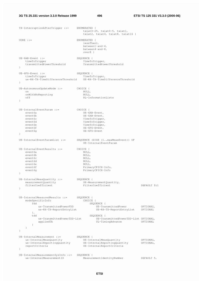
ETSI
ETSI TS 125 331 V3.3.0 (2000-06)4963G TS 25.331 version 3.3.0 Release 1999
TX-InterruptionAfterTrigger ::= ENUMERATED {txiat0-25, txiat0-5, txiat1,txiat2, txiat4, txiat8, txiat16 }
UDRE ::= ENUMERATED {lessThan1,between1-and-4,between4-and-8,over8 }
UE-6AB-Event ::= SEQUENCE {timeToTrigger TimeToTrigger,transmittedPowerThreshold TransmittedPowerThreshold
}
UE-6FG-Event ::= SEQUENCE {timeToTrigger TimeToTrigger,ue-RX-TX-TimeDifferenceThreshold UE-RX-TX-TimeDifferenceThreshold
}
UE-AutonomousUpdateMode ::= CHOICE {on NULL,onWithNoReporting NULL,off RL-InformationLists
}
UE-InternalEventParam ::= CHOICE {event6a UE-6AB-Event,event6b UE-6AB-Event,event6c TimeToTrigger,event6d TimeToTrigger,event6e TimeToTrigger,event6f UE-6FG-Event,event6g UE-6FG-Event
}
UE-InternalEventParamList ::= SEQUENCE (SIZE (1..maxMeasEvent)) OFUE-InternalEventParam
UE-InternalEventResults ::= CHOICE {event6a NULL,event6b NULL,event6c NULL,event6d NULL,event6e NULL,event6f PrimaryCPICH-Info,event6g PrimaryCPICH-Info
}
UE-InternalMeasQuantity ::= SEQUENCE {measurementQuantity UE-MeasurementQuantity,filterCoefficient FilterCoefficient DEFAULT fc1
}
UE-InternalMeasuredResults ::= SEQUENCE {modeSpecificInfo CHOICE {
fdd SEQUENCE {ue-TransmittedPowerFDD UE-TransmittedPower OPTIONAL,ue-RX-TX-ReportEntryList UE-RX-TX-ReportEntryList OPTIONAL
},tdd SEQUENCE {
ue-TransmittedPowerTDD-List UE-TransmittedPowerTDD-List OPTIONAL,appliedTA UL-TimingAdvance OPTIONAL
}}
}
UE-InternalMeasurement ::= SEQUENCE {ue-InternalMeasQuantity UE-InternalMeasQuantity OPTIONAL,ue-InternalReportingQuantity UE-InternalReportingQuantity OPTIONAL,reportCriteria UE-InternalReportCriteria
}
UE-InternalMeasurementSysInfo ::= SEQUENCE {ue-InternalMeasurementID MeasurementIdentityNumber DEFAULT 5,

ETSI
ETSI TS 125 331 V3.3.0 (2000-06)4973G TS 25.331 version 3.3.0 Release 1999
ue-InternalMeasQuantity UE-InternalMeasQuantity}
UE-InternalReportCriteria ::= CHOICE {ue-InternalReportingCriteria UE-InternalReportingCriteria,periodicalReportingCriteria PeriodicalReportingCriteria,noReporting NULL
}
UE-InternalReportingCriteria ::= SEQUENCE {ue-InternalEventParamList UE-InternalEventParamList OPTIONAL
}
UE-InternalReportingQuantity ::= SEQUENCE {ue-TransmittedPower BOOLEAN,modeSpecificInfo CHOICE {
fdd SEQUENCE {ue-RX-TX-TimeDifferece BOOLEAN
},tdd SEQUENCE {
appliedTA BOOLEAN}
}}
-- TABULAR: For TDD only the first two values are used.UE-MeasurementQuantity ::= ENUMERATED {
ue-TransmittedPower,utra-Carrier-RSSI,ue-RX-TX-TimeDifference }
UE-RX-TX-ReportEntry ::= SEQUENCE {primaryCPICH-Info PrimaryCPICH-Info,ue-RX-TX-TimeDifference UE-RX-TX-TimeDifference
}
UE-RX-TX-ReportEntryList ::= SEQUENCE (SIZE (1..maxRL)) OFUE-RX-TX-ReportEntry
UE-RX-TX-TimeDifference ::= INTEGER (876..1172)
UE-RX-TX-TimeDifferenceThreshold ::= INTEGER (769..1280)
UE-State ::= ENUMERATED {cell-DCH, all-But-Cell-DCH, all-States }
UE-TransmittedPower ::= INTEGER (-50..33)
UE-TransmittedPowerTDD-List ::= SEQUENCE (SIZE (1..maxTS)) OFUE-TransmittedPower
UTRA-CarrierRSSI ::= INTEGER (-95..-30)
UTRAN-ReferenceTime ::= SEQUENCE {gps-TOW GPS-TOW-1usec,sfn INTEGER (0..4095)
}
VarianceOfRLC-BufferPayload ::= ENUMERATED {plv0, plv4, plv8, plv16, plv32, plv64,plv128, plv256, plv512, plv1024,plv2k, plv4k, plv8k, plv16k }
-- Actual value = IE value * 0.1W ::= INTEGER (0..20)
END
11.3.8 Other information elementsOther-IEs DEFINITIONS AUTOMATIC TAGS ::=
BEGIN

ETSI
ETSI TS 125 331 V3.3.0 (2000-06)4983G TS 25.331 version 3.3.0 Release 1999
IMPORTS
CN-DomainSysInfoList,NAS-SystemInformationGSM-MAP,PLMN-Type
FROM CoreNetwork-IEs
CellAccessRestriction,CellIdentity,CellSelectReselectInfoSIB-3-4,URA-IdentityList
FROM UTRANMobility-IEs
CapabilityUpdateRequirement,CPCH-Parameters,DRAC-SysInfoList,ProtocolErrorCause,UE-ConnTimersAndConstants,UE-DCHTimersAndConstants,UE-IdleTimersAndConstants
FROM UserEquipment-IEs
PredefinedConfigIdentity,PredefinedConfigValueTag,PreDefRadioConfiguration
FROM RadioBearer-IEs
AICH-PowerOffset,ConstantValue,CPCH-PersistenceLevelsList,CPCH-SetInfoList,CSICH-PowerOffset,DynamicPersistenceLevelList,IndividualTS-InterferenceList,MidambleConfiguration,PDSCH-SysInfoList,PICH-PowerOffset,PRACH-SystemInformationList,PrimaryCCPCH-Info,PrimaryCCPCH-TX-Power,PUSCH-SysInfoList,SCCPCH-SystemInformationList,UL-Interference
FROM PhysicalChannel-IEs
FACH-MeasurementOccasionInfo,LCS-Alma-SIB-DataList,LCS-DGPS-SIB-Data,LCS-Ephe-SIB-Data,LCS-GPS-AssistanceSIB,LCS-OTDOA-AssistanceSIB,MeasurementControlSysInfo
FROM Measurement-IEs
ANSI-41-GlobalServiceRedirectInfo,ANSI-41-PrivateNeighborListInfo,ANSI-41-RAND-Information,ANSI-41-UserZoneID-Information
FROM ANSI-41-IEs
maxInterSysMessages,maxSIB,maxSIB-FACH
FROM Constant-definitions;
BCC ::= INTEGER (0..7)
BCCH-ModificationInfo ::= SEQUENCE {mib-ValueTag MIB-ValueTag,bcch-ModificationTime BCCH-ModificationTime OPTIONAL
}
-- Actual value = IE value * 8BCCH-ModificationTime ::= INTEGER (0..511)
BSIC ::= SEQUENCE {

ETSI
ETSI TS 125 331 V3.3.0 (2000-06)4993G TS 25.331 version 3.3.0 Release 1999
ncc NCC,bcc BCC
}
CBS-DRX-Level1Information ::= SEQUENCE {ctch-AllocationPeriod INTEGER (1..256),cbs-FrameOffset INTEGER (0..255)
}
CDMA2000-Message ::= SEQUENCE {msg-Type BIT STRING (SIZE (8)),payload BIT STRING (SIZE (1..512))
}
CDMA2000-MessageList ::= SEQUENCE (SIZE (1..maxInterSysMessages)) OFCDMA2000-Message
CellValueTag ::= INTEGER (1..4)
GSM-MessageList ::= SEQUENCE (SIZE (1..maxInterSysMessages)) OFBIT STRING (SIZE (1..512))
InterSystemHO-Failure ::= SEQUENCE {interSystemHO-FailureCause InterSystemHO-FailureCause OPTIONAL,interSystemMessage InterSystemMessage OPTIONAL
}
InterSystemHO-FailureCause ::= CHOICE {configurationUnacceptable NULL,physicalChannelFailure NULL,protocolError ProtocolErrorInformation,unspecified NULL,spare1 NULL,spare2 NULL,spare3 NULL
}
InterSystemMessage ::= CHOICE {gsm SEQUENCE {
gsm-MessageList GSM-MessageList},cdma2000 SEQUENCE {
cdma2000-MessageList CDMA2000-MessageList},spare1 NULL,spare2 NULL,spare3 NULL,spare4 NULL,spare5 NULL,spare6 NULL
}
MasterInformationBlock ::= SEQUENCE {mib-ValueTag MIB-ValueTag,plmn-Type PLMN-Type,-- TABULAR: The PLMN identity and ANSI-41 core network information-- are included in PLMN-Type.sib-ReferenceList SIB-ReferenceList,
-- Extension mechanism for non- release99 informationnonCriticalExtensions SEQUENCE {} OPTIONAL
}
MIB-ValueTag ::= INTEGER (1..8)
NCC ::= INTEGER (0..7)
PLMN-ValueTag ::= INTEGER (1..256)
PredefinedConfigIdentityAndValueTag ::= SEQUENCE {predefinedConfigIdentity PredefinedConfigIdentity,predefinedConfigValueTag PredefinedConfigValueTag
}
ProtocolErrorInformation ::= SEQUENCE {diagnosticsType CHOICE {
type1 SEQUENCE {protocolErrorCause ProtocolErrorCause

ETSI
ETSI TS 125 331 V3.3.0 (2000-06)5003G TS 25.331 version 3.3.0 Release 1999
},spare NULL
}}
SchedulingInformation ::= SEQUENCE {sib-Type SIB-TypeAndTag,scheduling SEQUENCE {
segCount SegCount DEFAULT 1,sib-Pos CHOICE {
-- The element name indicates the repetition period and the value-- (multiplied by two) indicates the position of the first segment.rep4 INTEGER (0..1),rep8 INTEGER (0..3),rep16 INTEGER (0..7),rep32 INTEGER (0..15),rep64 INTEGER (0..31),rep128 INTEGER (0..63),rep256 INTEGER (0..127),rep512 INTEGER (0..255),rep1024 INTEGER (0..511),rep2048 INTEGER (0..1023),rep4096 INTEGER (0..2047)
},sib-PosOffsetInfo SibOFF-List OPTIONAL
} OPTIONAL}
SegCount ::= INTEGER (1..16)
SegmentIndex ::= INTEGER (0..15)
-- Actual value = 2 * IE valueSFN-Prime ::= INTEGER (0..2047)
SIB-Data-fixed ::= BIT STRING (SIZE (222))
SIB-Data-variable ::= BIT STRING (SIZE (1..214))
SIB-ReferenceList ::= SEQUENCE (SIZE (1..maxSIB)) OFSchedulingInformation
SIB-ReferenceListFACH ::= SEQUENCE (SIZE (1..maxSIB-FACH)) OFSchedulingInformation
SIB-Type ::= ENUMERATED {masterInformationBlock,systemInformationBlockType1,systemInformationBlockType2,systemInformationBlockType3,systemInformationBlockType4,systemInformationBlockType5,systemInformationBlockType6,systemInformationBlockType7,systemInformationBlockType8,systemInformationBlockType9,systemInformationBlockType10,systemInformationBlockType11,systemInformationBlockType12,systemInformationBlockType13,systemInformationBlockType13-1,systemInformationBlockType13-2,systemInformationBlockType13-3,systemInformationBlockType13-4,systemInformationBlockType14,systemInformationBlockType15,systemInformationBlockType15-1,systemInformationBlockType15-2,systemInformationBlockType15-3,systemInformationBlockType16,spare1, spare2, spare3, spare4,spare5, spare6, spare7, spare8 }
SIB-TypeAndTag ::= CHOICE {sysInfoType1 PLMN-ValueTag,

ETSI
ETSI TS 125 331 V3.3.0 (2000-06)5013G TS 25.331 version 3.3.0 Release 1999
sysInfoType2 PLMN-ValueTag,sysInfoType3 CellValueTag,sysInfoType4 CellValueTag,sysInfoType5 CellValueTag,sysInfoType6 CellValueTag,sysInfoType7 NULL,sysInfoType8 CellValueTag,sysInfoType9 NULL,sysInfoType10 NULL,sysInfoType11 CellValueTag,sysInfoType12 CellValueTag,sysInfoType13 CellValueTag,sysInfoType13-1 CellValueTag,sysInfoType13-2 CellValueTag,sysInfoType13-3 CellValueTag,sysInfoType13-4 CellValueTag,sysInfoType14 CellValueTag,sysInfoType15 CellValueTag,sysInfoType16 PredefinedConfigIdentityAndValueTag
}
SibOFF ::= ENUMERATED {so2, so4, so6, so8, so10,so12, so14, so16, so18,so20, so22, so24, so26,so28, so30, so32 }
SibOFF-List ::= SEQUENCE (SIZE (1..15)) OFSibOFF
SysInfoType1 ::= SEQUENCE {-- Other IEs
sib-ReferenceList SIB-ReferenceList OPTIONAL,-- Core network IEs
cn-CommonGSM-MAP-NAS-SysInfo NAS-SystemInformationGSM-MAP,cn-DomainSysInfoList CN-DomainSysInfoList,
-- User equipment IEsue-IdleTimersAndConstants UE-IdleTimersAndConstants,ue-DCHTimersAndConstants UE-DCHTimersAndConstants,
-- Extension mechanism for non- release99 informationnonCriticalExtensions SEQUENCE {} OPTIONAL
}
SysInfoType2 ::= SEQUENCE {-- Other IEs
sib-ReferenceList SIB-ReferenceList OPTIONAL,-- UTRAN mobility IEs
ura-IdentityList URA-IdentityList,-- User equipment IEs
ue-ConnTimersAndConstants UE-ConnTimersAndConstants,-- Extension mechanism for non- release99 information
nonCriticalExtensions SEQUENCE {} OPTIONAL}
SysInfoType3 ::= SEQUENCE {-- Other IEs
sib-ReferenceList SIB-ReferenceList OPTIONAL,-- UTRAN mobility IEs
cellIdentity CellIdentity,cellSelectReselectInfo CellSelectReselectInfoSIB-3-4,cellAccessRestriction CellAccessRestriction,
-- Extension mechanism for non- release99 informationnonCriticalExtensions SEQUENCE {} OPTIONAL
}
SysInfoType4 ::= SEQUENCE {-- Other IEs
sib-ReferenceList SIB-ReferenceList OPTIONAL,-- UTRAN mobility IEs
cellIdentity CellIdentity,cellSelectReselectInfo CellSelectReselectInfoSIB-3-4,cellAccessRestriction CellAccessRestriction,
-- Extension mechanism for non- release99 informationnonCriticalExtensions SEQUENCE {} OPTIONAL

ETSI
ETSI TS 125 331 V3.3.0 (2000-06)5023G TS 25.331 version 3.3.0 Release 1999
}
SysInfoType5 ::= SEQUENCE {-- Other IEs
sib-ReferenceList SIB-ReferenceList OPTIONAL,-- Physical channel IEs
modeSpecificInfo CHOICE {fdd SEQUENCE {
pich-PowerOffset PICH-PowerOffset,aich-PowerOffset AICH-PowerOffset
},tdd SEQUENCE {
pusch-SysInfo PUSCH-SysInfoList OPTIONAL,pdsch-SysInfo PDSCH-SysInfoList OPTIONAL,midambleConfiguration MidambleConfiguration OPTIONAL
}},primaryCCPCH-Info PrimaryCCPCH-Info OPTIONAL,prach-SystemInformationList PRACH-SystemInformationList,sCCPCH-SystemInformationList SCCPCH-SystemInformationList,cbs-DRX-Level1Information CBS-DRX-Level1Information OPTIONAL,-- Conditional on any of the CTCH indicator IEs in-- sCCPCH-SystemInformationList
-- Extension mechanism for non- release99 informationnonCriticalExtensions SEQUENCE {} OPTIONAL
}
SysInfoType6 ::= SEQUENCE {-- Other IEs
sib-ReferenceList SIB-ReferenceList OPTIONAL,-- Physical channel IEs
modeSpecificInfo CHOICE {fdd SEQUENCE {
pich-PowerOffset PICH-PowerOffset,aich-PowerOffset AICH-PowerOffset,csich-PowerOffset CSICH-PowerOffset OPTIONAL
},tdd SEQUENCE {
pusch-SysInfo PUSCH-SysInfoList OPTIONAL,pdsch-SysInfo PDSCH-SysInfoList OPTIONAL,midambleConfiguration MidambleConfiguration OPTIONAL
}},primaryCCPCH-Info PrimaryCCPCH-Info OPTIONAL,prach-SystemInformationList PRACH-SystemInformationList,sCCPCH-SystemInformationList SCCPCH-SystemInformationList,cbs-DRX-Level1Information CBS-DRX-Level1Information OPTIONAL,-- Conditional on any of the CTCH indicator IEs in-- sCCPCH-SystemInformationList
-- Extension mechanism for non- release99 informationnonCriticalExtensions SEQUENCE {} OPTIONAL
}
SysInfoType7 ::= SEQUENCE {-- Other IEs
sib-ReferenceList SIB-ReferenceList OPTIONAL,-- Physical channel IEs
modeSpecificInfo CHOICE {fdd SEQUENCE {
ul-Interference UL-Interference},tdd NULL
},prach-Information-SIB5-List DynamicPersistenceLevelList,prach-Information-SIB6-List DynamicPersistenceLevelList OPTIONAL,
-- Extension mechanism for non- release99 informationnonCriticalExtensions SEQUENCE {} OPTIONAL
}
SysInfoType8 ::= SEQUENCE {-- Other IEs
sib-ReferenceList SIB-ReferenceList OPTIONAL,-- User equipment IEs
cpch-Parameters CPCH-Parameters,

ETSI
ETSI TS 125 331 V3.3.0 (2000-06)5033G TS 25.331 version 3.3.0 Release 1999
-- Physical channel IEscpch-SetInfoList CPCH-SetInfoList,
-- Extension mechanism for non- release99 informationnonCriticalExtensions SEQUENCE {} OPTIONAL
}
SysInfoType9 ::= SEQUENCE {-- Other IEs
sib-ReferenceList SIB-ReferenceList OPTIONAL,-- Physical channel IEs
cpch-PersistenceLevelsList CPCH-PersistenceLevelsList,-- Extension mechanism for non- release99 information
nonCriticalExtensions SEQUENCE {} OPTIONAL}
SysInfoType10 ::= SEQUENCE {-- Other IEs
sib-ReferenceList SIB-ReferenceList OPTIONAL,-- User equipment IEs
drac-SysInfoList DRAC-SysInfoList,-- Extension mechanism for non- release99 information
nonCriticalExtensions SEQUENCE {} OPTIONAL}
SysInfoType11 ::= SEQUENCE {-- Other IEs
sib-ReferenceList SIB-ReferenceList OPTIONAL,-- Measurement IEs
fach-MeasurementOccasionInfo FACH-MeasurementOccasionInfo OPTIONAL,measurementControlSysInfo MeasurementControlSysInfo,
-- Extension mechanism for non- release99 informationnonCriticalExtensions SEQUENCE {} OPTIONAL
}
SysInfoType12 ::= SEQUENCE {-- Other IEs
sib-ReferenceList SIB-ReferenceList OPTIONAL,-- Measurement IEs
fach-MeasurementOccasionInfo FACH-MeasurementOccasionInfo OPTIONAL,measurementControlSysInfo MeasurementControlSysInfo,
-- Extension mechanism for non- release99 informationnonCriticalExtensions SEQUENCE {} OPTIONAL
}
SysInfoType13 ::= SEQUENCE {-- Other IEs
sib-ReferenceList SIB-ReferenceList OPTIONAL,-- Core network IEs
cn-DomainSysInfoList CN-DomainSysInfoList,-- User equipment IEs
ue-IdleTimersAndConstants UE-IdleTimersAndConstants OPTIONAL,capabilityUpdateRequirement CapabilityUpdateRequirement OPTIONAL,
-- Extension mechanism for non- release99 informationnonCriticalExtensions SEQUENCE {} OPTIONAL
}
SysInfoType13-1 ::= SEQUENCE {-- ANSI-41 IEs
ansi-41-RAND-Information ANSI-41-RAND-Information,-- Extension mechanism for non- release99 information
nonCriticalExtensions SEQUENCE {} OPTIONAL}
SysInfoType13-2 ::= SEQUENCE {-- ANSI-41 IEs
ansi-41-UserZoneID-Information ANSI-41-UserZoneID-Information,-- Extension mechanism for non- release99 information
nonCriticalExtensions SEQUENCE {} OPTIONAL}
SysInfoType13-3 ::= SEQUENCE {-- ANSI-41 IEs
ansi-41-PrivateNeighborListInfo ANSI-41-PrivateNeighborListInfo,-- Extension mechanism for non- release99 information
nonCriticalExtensions SEQUENCE {} OPTIONAL}

ETSI
ETSI TS 125 331 V3.3.0 (2000-06)5043G TS 25.331 version 3.3.0 Release 1999
SysInfoType13-4 ::= SEQUENCE {-- ANSI-41 IEs
ansi-41-GlobalServiceRedirectInfoANSI-41-GlobalServiceRedirectInfo,
-- Extension mechanism for non- release99 informationnonCriticalExtensions SEQUENCE {} OPTIONAL
}
SysInfoType14 ::= SEQUENCE {-- Other IEs
sib-ReferenceList SIB-ReferenceList OPTIONAL,-- Physical channel IEs
primaryCCPCH-TX-Power PrimaryCCPCH-TX-Power OPTIONAL,individualTS-InterferenceList IndividualTS-InterferenceList,prach-ConstantValue ConstantValue OPTIONAL,dpch-ConstantValue ConstantValue OPTIONAL,pusch-ConstantValue ConstantValue OPTIONAL,
-- Extension mechanism for non- release99 informationnonCriticalExtensions SEQUENCE {} OPTIONAL
}
SysInfoType15 ::= SEQUENCE {-- Other IEs
sib-ReferenceList SIB-ReferenceList OPTIONAL,-- Measurement IEs
lcs-GPS-Assistance LCS-GPS-AssistanceSIB OPTIONAL,lcs-OTDOA-Assistance LCS-OTDOA-AssistanceSIB OPTIONAL,
-- Extension mechanism for non- release99 informationnonCriticalExtensions SEQUENCE {} OPTIONAL
}
SysInfoType15-1 ::= SEQUENCE {-- DGPS corrections
lcs-DGPS-SIB-Data LCS-DGPS-SIB-Data}
SysInfoType15-2 ::= SEQUENCE {-- Ephemeris and clock corrections
lcs-Ephe-SIB-Data LCS-Ephe-SIB-Data}
SysInfoType15-3 ::= SEQUENCE {-- Almanac and other data
transmissionTOW INTEGER (0..1048575),satMask BIT STRING (SIZE (32)),lsbTOW BIT STRING (SIZE (8)),lcs-Alma-SIB-DataList LCS-Alma-SIB-DataList
}
SysInfoType16 ::= SEQUENCE {-- Other IEs
sib-ReferenceList SIB-ReferenceList OPTIONAL,-- Radio bearer IEs
preDefinedRadioConfiguration PreDefRadioConfiguration,-- Extension mechanism for non- release99 information
nonCriticalExtensions SEQUENCE {} OPTIONAL}
END
11.3.9 ANSI-41 information elementsANSI-41-IEs DEFINITIONS AUTOMATIC TAGS ::=
BEGIN
ANSI-41-GlobalServiceRedirectInfo ::= ANSI-41-NAS-ParameterANSI-41-PrivateNeighborListInfo ::= ANSI-41-NAS-ParameterANSI-41-RAND-Information ::= ANSI-41-NAS-ParameterANSI-41-UserZoneID-Information ::= ANSI-41-NAS-ParameterANSI-41-NAS-Parameter ::= BIT STRING (SIZE (1..2048))
Min-P-REV ::= BIT STRING (SIZE (8))
NAS-SystemInformationANSI-41 ::= ANSI-41-NAS-Parameter

ETSI
ETSI TS 125 331 V3.3.0 (2000-06)5053G TS 25.331 version 3.3.0 Release 1999
NID ::= BIT STRING (SIZE (16))
P-REV ::= BIT STRING (SIZE (8))
SID ::= BIT STRING (SIZE (15))
END
11.4 Constant definitionsConstant-definitions DEFINITIONS AUTOMATIC TAGS ::=
BEGIN
hiRM INTEGER ::= 256maxAC INTEGER ::= 16maxAdditionalMeas INTEGER ::= 4maxASC INTEGER ::= 8maxASCmap INTEGER ::= 7maxASCpersist INTEGER ::= 6maxCCTrCH INTEGER ::= 8maxCellMeas INTEGER ::= 32maxCellMeas-1 INTEGER ::= 31
maxCNdomains INTEGER ::= 4maxCPCHsets INTEGER ::= 16maxDPCH-DLchan INTEGER ::= 8maxDPCHcodesPerTS INTEGER ::= 16
-- **TODO**maxDPDCH-UL INTEGER ::= 6maxDRACclasses INTEGER ::= 8-- **TODO**maxFACH INTEGER ::= 8maxFreq INTEGER ::= 8maxFrequencybands INTEGER ::= 4maxInterSysMessages INTEGER ::= 4maxLoCHperRLC INTEGER ::= 2maxMeasEvent INTEGER ::= 8maxMeasIntervals INTEGER ::= 3maxMeasParEvent INTEGER ::= 2maxNoOfMeas INTEGER ::= 16maxOtherRAT INTEGER ::= 15maxPage1 INTEGER ::= 8maxPCPCH-APsig INTEGER ::= 16maxPCPCH-APsubCh INTEGER ::= 12maxPCPCH-CDsig INTEGER ::= 16maxPCPCH-CDsubCh INTEGER ::= 12maxPCPCH-SF INTEGER ::= 7maxPCPCHs INTEGER ::= 64maxPDCPAlgoType INTEGER ::= 8maxPDSCH INTEGER ::= 8maxPDSCH-TFCIgroups INTEGER ::= 256maxPRACH INTEGER ::= 16maxPUSCH INTEGER ::= 8maxRABsetup INTEGER ::= 16maxRAT INTEGER ::= 16
maxRB INTEGER ::= 32maxRBallRABs INTEGER ::= 27maxRBMuxOptions INTEGER ::= 8maxRBperRAB INTEGER ::= 8maxRL INTEGER ::= 8maxRL-1 INTEGER ::= 7maxSat INTEGER ::= 16maxSCCPCH INTEGER ::= 16maxSIB INTEGER ::= 32-- **TODO**maxSIB-FACH INTEGER ::= 8maxSIBsegm INTEGER ::= 16maxSig INTEGER ::= 16maxSignallingFlow INTEGER ::= 16maxSRBsetup INTEGER ::= 8maxSubCh INTEGER ::= 12maxSystemCapability INTEGER ::= 16maxTF INTEGER ::= 32maxTF-CPCH INTEGER ::= 16

ETSI
ETSI TS 125 331 V3.3.0 (2000-06)5063G TS 25.331 version 3.3.0 Release 1999
maxTFC INTEGER ::= 1024maxTFCI-2-Combs INTEGER ::= 512maxTGPS INTEGER ::= 6maxTrCH INTEGER ::= 32maxTrCHpreconf INTEGER ::= 16maxTS INTEGER ::= 14maxURA INTEGER ::= 8
END
11.5 RRC information between network nodesInternode-definitions DEFINITIONS AUTOMATIC TAGS ::=
BEGIN
IMPORTS
HandoverToUTRANCommand,MeasurementReport,PhysicalChannelReconfiguration,RadioBearerReconfiguration,RadioBearerRelease,RadioBearerSetup,TransportChannelReconfiguration,UECapabilityInformation
FROM PDU-definitions
CN-DomainInformationList,NAS-SystemInformationGSM-MAP
FROM CoreNetwork-IEs
CellIdentity,URA-Identity
FROM UTRANMobility-IEs
C-RNTI,HyperFrameNumber,RRC-MessageSequenceNumber,U-RNTI,UE-RadioAccessCapability
FROM UserEquipment-IEs
PDCP-InfoReconfig,RAB-Info,RB-Identity,RB-MappingInfo,RLC-Info,RLC-SequenceNumber,SRB-InformationSetup
FROM RadioBearer-IEs
TFC-Subset,TFCS,TransportChannelIdentity,TransportFormatSet
FROM TransportChannel-IEs
MeasurementIdentityNumber,MeasurementReportingMode,MeasurementType,AdditionalMeasurementID-List
FROM Measurement-IEs
InterSystemMessageFROM Other-IEs
maxNoOfMeas,maxRABsetup,maxRB,maxSRBsetup,maxTrCH
FROM Constant-definitions;
CalculationTimeForCiphering ::= SEQUENCE {cell-Id CellIdentity,

ETSI
ETSI TS 125 331 V3.3.0 (2000-06)5073G TS 25.331 version 3.3.0 Release 1999
sfn INTEGER (0..4095)}
CipheringInfoPerRB ::= SEQUENCE {dl-HFN HyperFrameNumber,ul-HFN HyperFrameNumber,dl-RLC-SequenceNumber RLC-SequenceNumber,ul-RLC-SequenceNumber RLC-SequenceNumber
}
-- TABULAR: Multiplicity value numberOfRadioBearers has been replaced-- with maxRB.CipheringInfoPerRB-List ::= SEQUENCE (SIZE (1..maxRB)) OF
CipheringInfoPerRB
CipheringStatus ::= ENUMERATED {started, notStarted }
ImplementationSpecificParams ::= BIT STRING (SIZE (1..512))
-- **TODO** Upper limit N316 is undefined! An arbitrary upper limit of-- 7 has been used here instead.IntegrityProtectionFailureCount ::= INTEGER (0..7)
IntegrityProtectionStatus ::= ENUMERATED {started, notStarted }
MeasurementCommandWithType ::= CHOICE {setup MeasurementType,modify NULL,release NULL
}
OngoingMeasRep ::= SEQUENCE {measurementIdentityNumber MeasurementIdentityNumber,measurementCommandWithType MeasurementCommandWithType,-- TABULAR: The CHOICE Measurement in the tabular description is included-- in the IE above.measurementReportingMode MeasurementReportingMode OPTIONAL,additionalMeasurementID-List AdditionalMeasurementID-List OPTIONAL
}
OngoingMeasRepList ::= SEQUENCE (SIZE (1..maxNoOfMeas)) OFOngoingMeasRep
RAB-Information ::= SEQUENCE {rab-Info RAB-Info,rb-InformationList RB-InformationList OPTIONAL
}
RAB-InformationList ::= SEQUENCE (SIZE (1..maxRABsetup)) OFRAB-Information
RB-Information ::= SEQUENCE {rb-Identity RB-Identity,rlc-Info RLC-Info,pdcp-Info PDCP-InfoReconfig OPTIONAL,rb-MappingInfo RB-MappingInfo
}
RB-InformationList ::= SEQUENCE (SIZE (1..maxRB)) OFRB-Information
-- ***************************************************---- Source RNC to target RNC---- ***************************************************
SourceRNCToTargetRNC ::= SEQUENCE {-- Non-RRC IEs
stateOfRRC StateOfRRC,stateOfRRC-Procedure StateOfRRC-Procedure,cipheringStatus CipheringStatus,calculationTimeForCiphering CalculationTimeForCiphering OPTIONAL,cipheringInfoPerRB-List CipheringInfoPerRB-List OPTIONAL,integrityProtectionStatus IntegrityProtectionStatus,

ETSI
ETSI TS 125 331 V3.3.0 (2000-06)5083G TS 25.331 version 3.3.0 Release 1999
integrityProtectionFailureCount IntegrityProtectionFailureCount,srb-SpecificIntegrityProtInfo SRB-SpecificIntegrityProtInfoList,implementationSpecificParams ImplementationSpecificParams OPTIONAL,
-- User equipment IEsu-RNTI U-RNTI,c-RNTI C-RNTI OPTIONAL,ue-RadioAccessCapability UE-RadioAccessCapability,
-- Other IEsinterSystemMessage InterSystemMessage OPTIONAL,
-- UTRAN mobility IEsura-Identity URA-Identity OPTIONAL,
-- Core network IEscn-CommonGSM-MAP-NAS-SysInfo NAS-SystemInformationGSM-MAP,cn-DomainInformationList CN-DomainInformationList OPTIONAL,
-- Measurement IEsongoingMeasRepList OngoingMeasRepList OPTIONAL,
-- Radio bearer IEssrb-InformationList SRB-InformationList,rab-InformationList RAB-InformationList OPTIONAL,
-- Transport channel IEsul-DCH-TFCS TFCS OPTIONAL,dl-DCH-TFCS TFCS OPTIONAL,ul-DCH-TFC-Subset TFC-Subset OPTIONAL,usch-TFCS TFCS OPTIONAL,dsch-TFCS TFCS OPTIONAL,usch-TFC-Subset TFC-Subset OPTIONAL,ul-TransChInfoList TransChInfoList OPTIONAL,dl-TransChInfoList TransChInfoList OPTIONAL,
-- Measurement reportmeasurementReport MeasurementReport OPTIONAL
}
-- ***************************************************---- Source system to target RNC---- ***************************************************
SourceSystemToTargetRNC ::= CHOICE {ueCapabilityInformation UECapabilityInformation,spare NULL
}
SRB-InformationList ::= SEQUENCE (SIZE (3..maxSRBsetup)) OFSRB-InformationSetup
SRB-SpecificIntegrityProtInfo ::= SEQUENCE {ul-HFN HyperFrameNumber,dl-HFN HyperFrameNumber,ul-RRC-SequenceNumber RRC-MessageSequenceNumber,dl-RRC-SequenceNumber RRC-MessageSequenceNumber
}
SRB-SpecificIntegrityProtInfoList ::= SEQUENCE (SIZE (3..maxSRBsetup)) OFSRB-SpecificIntegrityProtInfo
StateOfRRC ::= ENUMERATED {cell-DCH, cell-FACH,cell-PCH, ura-PCH }
StateOfRRC-Procedure ::= ENUMERATED {awaitNoRRC-Message,awaitRRC-ConnectionRe-establishmentComplete,awaitRB-SetupComplete,awaitRB-ReconfigurationComplete,awaitTransportCH-ReconfigurationComplete,awaitPhysicalCH-ReconfigurationComplete,awaitActiveSetUpdateComplete,awaitHandoverComplete,otherStates }
-- ***************************************************---- Target system to source RNC---- ***************************************************
TargetSystemToSourceRNC ::= CHOICE {

ETSI
ETSI TS 125 331 V3.3.0 (2000-06)5093G TS 25.331 version 3.3.0 Release 1999
radioBearerSetup RadioBearerSetup,radioBearerReconfiguration RadioBearerReconfiguration,radioBearerRelease RadioBearerRelease,transportChannelReconfiguration TransportChannelReconfiguration,physicalChannelReconfiguration PhysicalChannelReconfiguration,handoverToUTRANCommand HandoverToUTRANCommand
}
TransChInfo ::= SEQUENCE {transportChannelIdentity TransportChannelIdentity,transportFormatSet TransportFormatSet
}
TransChInfoList ::= SEQUENCE (SIZE (1..maxTrCH)) OFTransChInfo
END

ETSI
ETSI TS 125 331 V3.3.0 (2000-06)5103G TS 25.331 version 3.3.0 Release 1999
12 Message transfer syntaxTransfer syntax for RRC PDUs is derived from their abstract syntax definitions by use of Packed Encoding Rules,unaligned (X.691). If special encoding is used, it is indicated in the ECN module defined for each ASN.1 module. Howspecial encoding is used is defined in TR 25.921.
12.1 Padding of RRC messages using RLC transparent modePadding is applicable for all UL and DL RRC messages using transparent RLC mode.
On the transmitter side, padding is inserted after the message has been encoded using the specified encoding rule. TheRRC layer shall insert padding at the end of the message until the size of the RRC PDU equals the transport block size.
If the TFS contains more than one transport block size, the RRC layer shall select the smallest possible transport blocksize to use for the transfer of the message. Padding shall be inserted at the end of the message until the size of the RRCPDU equals the size of the selected transport block.
The value of the padding bits shall be "0".
On the receiver side, the padding bits shall be ignored.
12.2 ECN link module for RRCRRC-ECN-Link-Module LINK-DEFINITIONS ::=BEGIN
Class-definitions ENCODED BY perUnaligned WITH Class-definitions-ECN-ModulePDU-definitions ENCODED BY perUnaligned WITH PDU-definitions-ECN-ModuleCoreNetwork-IEs ENCODED BY perUnaligned WITH CoreNetwork-IEs-ECN-ModuleUTRANMobility-IEs ENCODED BY perUnaligned WITH UTRANMobility-IEs-ECN-ModuleUserEquipment-IEs ENCODED BY perUnaligned WITH UserEquipment-IEs-ECN-ModuleRadioBearer-IEs ENCODED BY perUnaligned WITH RadioBearer-IEs-ECN-ModuleTransportChannel-IEs ENCODED BY perUnaligned WITH TrasportChannel-IEs-ECN-ModulePhysicalChannel-IEs ENCODED BY perUnaligned WITH PhysicalChannel-IEs-ECN-ModuleMeasurement-IEs ENCODED BY perUnaligned WITH Measurement-IEs-ECN-ModuleOther-IEs ENCODED BY perUnaligned WITH Other-IEs-ECN-ModuleANSI-41-IEs ENCODED BY perUnaligned WITH ANSI-41-IEs-ECN-Module
END
12.3 ECN modules for RRCClass-definitions-ECN-Module ENCODING-DEFINITIONS ::=BEGINEND
PDU-definitions-ECN-Module ENCODING-DEFINITIONS ::=BEGINEND
Corenetwork-IEs-ECN-Module ENCODING-DEFINITIONS ::=BEGINEND
UTRANMobility-IEs-ECN-Module ENCODING-DEFINITIONS ::=BEGINEND
UserEquipment-IEs-ECN-Module ENCODING-DEFINITIONS ::=BEGINEND
RadioBearer-IEs-ECN-Module ENCODING-DEFINITIONS ::=BEGINEND
TransportChannel-IEs-ECN-Module ENCODING-DEFINITIONS ::=BEGINEND

ETSI
ETSI TS 125 331 V3.3.0 (2000-06)5113G TS 25.331 version 3.3.0 Release 1999
PhysicalChannel-IEs-ECN-Module ENCODING-DEFINITIONS ::=BEGINEND
Measurement-IEs-ECN-Module ENCODING-DEFINITIONS ::=BEGINEND
Other-IEs-ECN-Module ENCODING-DEFINITIONS ::=BEGINEND
ANSI-41-IEs-ECN-Module ENCODING-DEFINITIONS ::=BEGINEND

ETSI
ETSI TS 125 331 V3.3.0 (2000-06)5123G TS 25.331 version 3.3.0 Release 1999
13 Protocol timers, counters and other parameters
13.1 Timers for UETimer Start Stop At expiry
T300 Transmission of RRCCONNECTION REQUEST
Reception of RRCCONNECTION SETUP
Retransmit RRCCONNECTIONREQUEST if V300=< N300, else goto Idle mode
T301 Transmission of RRCCONNECTIONREESTABLISHMENTREQUEST
Reception of RRCCONNECTIONREESTABLISHMENT
See subclause8.1.5.8.
T302 Transmission of CELLUPDATE
Reception of CELL UPDATECONFIRM
Retransmit CELLUPDATE if V302=< N302, else, goto Idle mode
T303 Transmission of URAUPDATE
Reception of URA UPDATECONFIRM
Retransmit URAUPDATE if V303=< N303, else goto Idle mode
T304 Transmission of UECAPABILITY INFORMATION
Reception of UECAPABILITYINFORMATION CONFIRM
Retransmit UECAPABILITYINFORMATION ifV304 =< N304,else initiate RRCconnectionreestablishment
T305 Entering CELL_FACH orCELL_PCH state. Receptionof CELL UDPATE CONFIRM.
Entering another state. Transmit CELLUPDATE if T307is not activated.
T306 Entering URA_PCH state.Reception of URA UDPATECONFIRM.
Entering another state. Transmit URAUPDATE if T307is not activated.
T307 When the timer T305 or T306has expired and the UEdetects "out of service area".
When the UE detects "inservice area". Or,initiate cell update or URAupdate procedure dependingon state
Transit to idlemode
T308 Transmission of RRCCONNECTION RELEASECOMPLETE
Not stopped Transmit RRCCONNECTIONRELEASECOMPLETE ifV308 =< N308,else go to idlemode.
T309 Upon reselection of a cellbelonging to another radioaccess system from connectedmode
Successful establishment ofa connection in the new cell
Resume theconnection toUTRAN
T310 Transmission of PUSCHCAPACITY REQUEST
Reception of PHYSICALSHARED CHANNELALLOCATION
Transmit PUSCHCAPACITYREQUEST if V310=< N310, elseprocedure stops.
T311 Reception of PHYSICALSHARED CHANNELALLOCATION message withthe parameter "PUSCHAllocation Pending" set to"pending".
Reception of PHYSICALSHARED CHANNELALLOCATION message withparameter "PUSCHAllocation Pending" set to"not pending".
UE may initiate aPUSCH capacityrequestprocedure.

ETSI
ETSI TS 125 331 V3.3.0 (2000-06)5133G TS 25.331 version 3.3.0 Release 1999
T312 When the UE starts toestablish dedicated CH
When the UE detectsconsecutive N312 "in sync"indication from L1.
The criteria forphysical channelestablishmentfailure is fulfilled
T313 When the UE detectsconsecutive N313 "out ofsync" indication from L1.
When the UE detectsconsecutive N315 "in sync"indication from L1.
The criteria forRadio Link failureis fulfilled
T314 When the UE detects that it isout of sync.The timer is started only ifradio bearer(s) which areassociated with T314 exist.
When the RRC ConnectionRe-establishment procedurehas been completed.
See subclause8.1.5.6
T315 When the UE detects that it isout of sync.The timer is started only ifradio bearer(s) which areassociated with T315 exist.
When the RRC ConnectionRe-establishment procedurehas been completed.
See subclause8.1.5.7
13.2 Counters for UECounter Reset Incremented When reaching max value
V300 When initiating theprocedure RRCconnectionestablishment
Upon expiry of T300. When V300 > N300, the UE enters idle mode.
V302 When initiating theprocedure Cellupdate
Upon expiry of T302 When V302 > N302 the UE enters idle mode.
V303 When initiating theprocedure URAupdate
Upon expiry of T303 When V302 > N303 the UE enters idle mode.
V304 When sending thefirst UE CAPABILITYINFORMATIONmessage.
Upon expiry of T304 When V304 > N304 the UE initiates the RRCconnection re-establishment procedure
Counter Reset Decremented When reaching zeroV308 When sending the
first RRCCONNECTIONRELEASECOMPLETEmessage in a RRCconnection releaseprocedure.
Upon expiry of T308 When V308 =0 the UE stops re-transmittingthe RRC CONNECTION RELEASECOMPLETE message.
Counter Reset Incremented When reaching max valueV310 When sending the
first PUSCHCAPACITYREQUEST messagein a PUSCH capacityrequest procedure
Upon expiry of T310 When V310 > N310 the UE stops re-transmitting the PUSCH CAPACITYREQUEST message.

ETSI
ETSI TS 125 331 V3.3.0 (2000-06)5143G TS 25.331 version 3.3.0 Release 1999
13.3 UE constants and parametersConstant Usage
N300 Maximum number of retransmissions of the RRC CONNECTION REQUESTmessage
N301 Maximum number of retransmissions of the RRC CONNECTIONREESTABLISHMENT REQUEST message
N302 Maximum number of retransmissions of the CELL UPDATE messageN303 Maximum number of retransmissions of the URA UPDATE messageN304 Maximum number of retransmissions of the UE CAPABILITY INFORMATION
messageN310 Maximum number of retransmission of the PUSCH CAPACITY REQUEST messageN312 Maximum number of successive "in sync" received from L1.N313 Maximum number of successive "out of sync" received from L1.N315 Maximum number of successive "in sync" received from L1 during T313 is activated.
13.4 UE variables
13.4.1 CIPHERING_STATUS
This variable contains information about the current status of ciphering in the UE.
Information Element/Groupname
Need Multi Type andreference
Semantics description
Status MP Enumerated(Not started,Started)
13.4.2 DEFAULT_TFC_SUBSET
This variable contains the TFC subset to go back to when a temporary TFC limitation is released.
Information Element/Groupname
Need Multi Type andreference
Semantics description
TFC subset MP TransportFormatCombinationSubset10.3.5.22
13.4.3 ESTABLISHED_RABS
This variable is used to store information about the established radio access bearers in the UE.

ETSI
ETSI TS 125 331 V3.3.0 (2000-06)5153G TS 25.331 version 3.3.0 Release 1999
Information Element/Groupname
Need Multi Type andreference
Semantics description
RAB information OP 1 to<maxRABsetup>
For each RAB established
>RAB info MP RAB info10.3.4.8
>RB information MP 1 to<maxRBperRAB>
For each RB belonging to theRAB
>>RB identity MP RB identity10.3.4.13
>>Subflow MP Integer(0..<maxSubflowcount>)
Reference to the RAB subflowimplemented by this RB
13.4.4 INTEGRITY_PROTECTION_INFO
This variable contains information about the current status of the integrity protection in the UE.
Information Element/Groupname
Need Multi Type andreference
Semantics description
Status MP Enumerated(Notstarted,Started)
Signalling radio bearer specificintegrity protection information
MP 1 to<maxSRBsetup>
Status information for RB#0-4in that order
> Uplink HFN MP Hyperframenumber10.3.3.13
> Downlink HFN MP Hyperframenumber10.3.3.13
> Uplink RRC Messagesequence number
MP Integer (0..15)
> Downlink RRC Messagesequence number
MP Integer (0..15)
13.4.5 MEASUREMENT_IDENTITY
This variable stores the measurements configured in the UE. For each configured measurement, the information belowshall be stored.
Information Element/Groupname
Need Multi Type andreference
Semantics description
MEASUREMENT CONTROL MP MEASUREMENTCONTROL10.2.15
Information as contained inthis message.
13.4.6 ORDERED_ASU
NOTE: For FDD only.
This variable stores information about an ordered, but not yet executed, update of active set.

ETSI
ETSI TS 125 331 V3.3.0 (2000-06)5163G TS 25.331 version 3.3.0 Release 1999
Information Element/Groupname
Need Multi Type andreference
Semantics description
ACTIVE SET UPDATE MP ACTIVESETUPDATE10.2.1
Information as contained inthis message.
13.4.7 ORDERED_CONFIG
This variable stores information about an ordered but not yet executed establishment/release/reconfiguration of radiobearers, and/or transport channels and/or physical channels.
Information Element/Groupname
Need Multi Type andreference
Semantics description
CHOICE message MP Information as contained inone of the following messages
>RADIO BEARER SETUP RADIOBEARERSETUP10.2.31
>RADIO BEARERRECONFIGURATION
RADIOBEARERRECONFIGURATION10.2.25
>RADIO BEARER RELEASE RADIOBEARERRELEASE10.2.28
>TRANSPORT CHANNELRECONFIGURATION
TRANSPORT CHANNELRECONFIGURATION10.2.54
>PHYSICAL CHANNELRECONFIGURATION
PHYSICALCHANNELRECONFIGURATION10.2.20
13.4.8 PROTOCOL_ERROR_INDICATOR
This variable indicates whether there exist a protcol error that is to be reported to UTRAN.
Information Element/Groupname
Need Multi Type andreference
Semantics description
Protocol error indicator MP Protocol errorindicator10.3.3.28
13.4.9 PROTOCOL_ERROR_INFORMATION
This varaible contains diagnostics to be reported to UTRAN for a message that was not completely understood.
Information Element/Groupname
Need Multi Type andreference
Semantics description
Protocol error information MP Protocolerrorinformation10.3.8.10

ETSI
ETSI TS 125 331 V3.3.0 (2000-06)5173G TS 25.331 version 3.3.0 Release 1999
13.4.10 PROTOCOL_ERROR_REJECT
This variable indicates whether there has occurred a severe protocol error causing the ongoing procedure to fail.
Information Element/Groupname
Need Multi Type andreference
Semantics description
Protocol error reject MP Boolean TRUE: a severe protocolerror has occurred
13.4.11 RB_UPLINK_CIPHERING_ACTIVATION_TIME_INFO
This variable contains information to be sent to UTRAN about when a new ciphering configuration shall be activated inthe uplink for radio bearers using RLC-AM or RLC-UM.
Information Element/Groupname
Need Multi Type andreference
Semantics description
RB uplink ciphering activationtime info
MP RBactivationtime info10.3.4.10
13.4.12 SELECTED_PLMN
This variable contains the type of and identity of the selected PLMN.
Information Element/Groupname
Need Multi Type andreference
Semantics description
PLMN Type MP PLMN Type10.3.1.12
CHOICE identity type MP>PLMN identity PLMN
identity10.3.1.11
>SID SID10.3.9.11
CHOICE identity type Condition under which the given identity type ischosen
PLMN identity PLMN Type is "GSM-MAP"SID PLMN Type is "ANSI-41"
13.4.13 TGPS_IDENTITY
This variable contains the configuration parameters of a compressed mode transmission gap pattern sequence
Information Element/Groupname
Need Multi Type andreference
Semantics description
TGPS_IDENTITY MP DPCHcompressedmode info10.3.6.27
Information as contained in theIE group "Transmission gappattern sequence configurationparameters".
13.4.14 UE_CAPABILITY_TRANSFERRED
This variable stores information about which UE capabilities that have been transferred to UTRAN.

ETSI
ETSI TS 125 331 V3.3.0 (2000-06)5183G TS 25.331 version 3.3.0 Release 1999
Information Element/Groupname
Need Multi Type andreference
Semantics description
UE radio access capability OP UE radioaccesscapability10.3.3.40
UE system specific capability OP Inter-systemmessage10.3.8.6
Includes inter-systemclassmark
13.4.15 UNACCEPTABLE_CONFIGURATION
This variable contains information on whether the received configuration from the UTRAN resulted in an illegalconfiguration.
Information Element/Groupname
Need Multi Type andreference
Semantics description
UNACCEPTABLE_CONFIGURATION
MP Boolean
13.4.16 VALUE_TAG
This variable contains information about the value tag for the last received system information block of a given type, forall system information blocks using value tags.

ETSI
ETSI TS 125 331 V3.3.0 (2000-06)5193G TS 25.331 version 3.3.0 Release 1999
Information Element/Groupname
Need Multi Type andreference
Semantics description
MIB value tag MP MIB value tag10.3.8.7
Value tag for the masterinformation block
SIB 1 value tag CV-GSM PLMN value tag10.3.8.8
Value tag for the systeminformation block type 1
SIB 2 value tag MP PLMN value tag10.3.8.8
Value tag for the systeminformation block type 2
SIB 3 value tag MP Cell value tag10.3.8.4
Value tag for the systeminformation block type 3
SIB 4 value tag MP Cell value tag10.3.8.4
Value tag for the systeminformation block type 4
SIB 5 value tag MP Cell value tag10.3.8.4
Value tag for the systeminformation block type 5
SIB 6 value tag MP Cell value tag10.3.8.4
Value tag for the systeminformation block type 6
CHOICE mode>FDD>>SIB 8 value tag MP Cell value tag
10.3.8.4Value tag for the systeminformation block type 8
>TDD (no data)SIB 11 value tag MP Cell value tag
10.3.8.4Value tag for the systeminformation block type 11
SIB 12 value tag MP Cell value tag10.3.8.4
Value tag for the systeminformation block type 12
SIB 13 value tag CV-ANSI Cell value tag10.3.8.4
Value tag for the systeminformation block type 13
SIB 13.1 value tag CV-ANSI Cell value tag10.3.8.4
Value tag for the systeminformation block type 13.1
SIB 13.2 value tag CV-ANSI Cell value tag10.3.8.4
Value tag for the systeminformation block type 13.2
SIB 13.3 value tag CV-ANSI Cell value tag10.3.8.4
Value tag for the systeminformation block type 13.3
SIB 13.4 value tag CV-ANSI Cell value tag10.3.8.4
Value tag for the systeminformation block type 13.4
CHOICE mode> TDD>>SIB 14 value tag MP Cell value tag
10.3.8.4Value tag for the systeminformation block type 14
> FDD (no data)SIB 15 value tag MP Cell value tag
10.3.8.4Value tag for the systeminformation block type 15
SIB 16 value tag MP PLMN value tag10.3.8.8
Value tag for the systeminformation block type 16
Condition ExplanationGSM This information is only stored when the PLMN Type
in the variable SELECTED_PLMN is "GSM-MAP".ANSI This information is only stored when the PLMN Type
in the variable SELECTED_PLMN is "ANSI-41".
14 Specific functions
14.1 Intra-frequency measurements
14.1.1 Intra-frequency measurement quantities
1 Downlink Ec/I0 (chip energy per total received channel power density).

ETSI
ETSI TS 125 331 V3.3.0 (2000-06)5203G TS 25.331 version 3.3.0 Release 1999
2 Downlink path loss.
3 Downlink received signal code power (RSCP) after despreading.
4 ISCP measured on Timeslot basis.
14.1.2 Intra-frequency reporting events for FDD
Within the measurement reporting criteria field in the Measurement Control message the UTRAN notifies the UEwhich events should trigger a measurement report. Examples of intra-frequency reporting events that would be usefulfor intra-frequency handover evaluation are given below. Note that normally the UEs do not need to report all theseevents. The listed events are the toolbox from which the UTRAN can choose the reporting events that are needed for theimplemented handover evaluation function, or other radio network functions.
All the illustrated events are measured with respect to any of the measurement quantities given in subclause 14.1.1. Themeasurement objects are the monitored primary common pilot channels (CPICH). The reporting events are marked withvertical arrows in the figures below.
NOTE: The events below are numbered 1A, 1B, 1C,… since all intra-frequency reporting events would belabelled 1X, inter-frequency reporting events would be labelled 2X, and so on for the other measurementtypes.
14.1.2.1 Reporting event 1A: A Primary CPICH enters the reporting range
When event 1A is ordered by UTRAN in a measurement control message, the UE shall send a measurement reportwhen a primary CPICH enters the reporting range as defined by the following formula:
For pathloss:
),(10)1(1010 11
aBest
N
iiNew HRLogMWMLogWLogM
A
++⋅⋅−+
⋅⋅≥⋅ ∑
=
For all the other measurement quantity:
),(10)1(1010 11
aBest
N
iiNew HRLogMWMLogWLogM
A
+−⋅⋅−+
⋅⋅≥⋅ ∑
=
The variables in the formula are defined as follows:
MNew is the measurement result of the cell entering the reporting range.
Mi is a measurement result of a cell in the active set.
NA is the number of cells in the current active set.
MBest is the measurement result of the strongest cell in the active set.
W is a parameter sent from UTRAN to UE.
R is the reporting range
H1a is the hysteresis parameter for the event 1a.
The addition window of cells in event 1A is configured with the reporting range parameter (R) common to manyreporting events and an optional hysteresis parameter (H1a), which can be used to distinguish the addition windowfrom reporting windows related to other measurement events.
The occurrence of event 1A is conditional on a report deactivation threshold parameter. This parameter indicates themaximum number of cells allowed in the active set for measurement reports to be triggered by event 1A to betransmitted.

ETSI
ETSI TS 125 331 V3.3.0 (2000-06)5213G TS 25.331 version 3.3.0 Release 1999
Event 1A may be enhanced with an addition timer, which is configured with the time-to-trigger parameter (seesubclause 14.1.4.2). If a time-to-trigger value is used, a cell must continuously stay within the reporting range for thegiven time period, before the UE shall send a measurement report.
Event 1A may be used for triggering a measurement report, which includes unlisted cells, which the UE has detected.
14.1.2.2 Reporting event 1B: A primary CPICH leaves the reporting range
When this event is ordered by UTRAN in a measurement control message, the UE shall send a measurement reportwhen a primary CPICH leaves the reporting range as defined by the following formula:
For pathloss:
),(10)1(1010 11
aBest
N
iiNew HRLogMWMLogWLogM
A
++⋅⋅−+
⋅⋅≤⋅ ∑
=
For all the other measurement quantity:
),(10)1(1010 11
bBest
N
iiOld HRLogMWMLogWLogM
A
+−⋅⋅−+
⋅⋅≤⋅ ∑
=
The variables in the formula are defined as follows:
MOld is the measurement result of the cell leaving the reporting range.
Mi is a measurement result of a cell in the active set.
NA is the number of cells in the current active set.
MBest is the measurement result of the strongest cell in the active set.
W is a parameter sent from UTRAN to UE.
R is the reporting range
H1b is the hysteresis parameter for the event 1b.
The drop window of cells in event 1B is configured with the reporting range parameter (R) common to many reportingevents and an optional hysteresis parameter (H1b), which can be used to distinguish the drop window from reportingwindows related to other measurement events.
Event 1B may be enhanced with a drop timer, which is configured with the time-to-trigger parameter. If the timer isused, the weakening cell must continuously stay below the reporting range for the given time period before the UE maysend a measurement report.

ETSI
ETSI TS 125 331 V3.3.0 (2000-06)5223G TS 25.331 version 3.3.0 Release 1999
14.1.2.3 Reporting event 1C: A non-active primary CPICH becomes better than anactive primary CPICH
Reportingevent 1C
Reportingevent 1C
Measurementquantity
Time
P CPICH 2
P CPICH 1
P CPICH 3
P CPICH 4
Figure 57: A primary CPICH that is not included in the active set becomes better than a primaryCPICH that is in the active set
In this example the cells belonging to primary CPICH 1, 2 and 3 are supposed to be in the active set, but the celltransmitting primary CPICH 4 is not (yet) in the active set.
If a primary CPICH that is not included in the active set becomes better than a primary CPICH that is in the active set,and event 1C has been ordered by UTRAN, this event shall trigger a report to be sent from the UE.
This event may be used for replacing cells in the active set. It is activated if the number of active cells is equal to orgreater than a replacement activation threshold parameter that UTRAN signals to the UE in the MEASUREMENTCONTROL message. This parameter indicates the minimum number of cells required in the active set for measurementreports triggered by event 1C to be transmitted.
14.1.2.4 Reporting event 1D: Change of best cell
Reportingevent 1D
Measurementquantity
Time
P CPICH 2
P CPICH 1
P CPICH3
Figure 58: A primary CPICH becomes better than the previously best primary CPICH
If any of the primary CPICHs within the reporting range becomes better than the previously best primary CPICH, andevent 1D has been ordered by UTRAN then this event shall trigger a report to be sent from the UE. The correspondingreport contains (at least) the new best primary CPICH.

ETSI
ETSI TS 125 331 V3.3.0 (2000-06)5233G TS 25.331 version 3.3.0 Release 1999
14.1.2.5 Reporting event 1E: A Primary CPICH becomes better than an absolutethreshold
Absolutethreshold
Reportingevent 1E
Measurementquantity
Time
P CPICH 1
P CPICH 2
P CPICH 3
Figure 59: Event-triggered report when a Primary CPICH becomes better than an absolute threshold
When this event is ordered by UTRAN in a measurement control message the UE shall send a report when theMeasurement quantity of a Primary CPICH becomes better than an absolute threshold. The corresponding reportcontains (at least) the involved Primary CPICH.
Event 1E may be used for triggering a measurement report, which includes unlisted cells, which the UE has detected.
14.1.2.6 Reporting event 1F: A Primary CPICH becomes worse than an absolutethreshold
Absolutethreshold
Reportingevent 1F
Measurementquantity
Time
P CPICH 1
P CPICH 2
P CPICH 3
Figure 60: Event-triggered report when a Primary CPICH becomes worse than an absolute threshold
When this event is ordered by the UTRAN in a measurement control message the UE shall send a report when aprimary CPICH becomes worse than an absolute threshold. The corresponding report contains (at least) the involvedPrimary CPICH.

ETSI
ETSI TS 125 331 V3.3.0 (2000-06)5243G TS 25.331 version 3.3.0 Release 1999
14.1.3 Intra-frequency reporting events for TDD
14.1.3.1 Reporting event 1G: Change of best cell (TDD)
ReportingEvent 1G
Measurementquantity
Time
P CCPCH 2
P CCPCH 1
Figure 61: A primary CCPCH becomes better than the previous best primary CCPCH
If any of the primary CCPCHs becomes better than the previously best primary CCPCH, and event 1G has been orderedby UTRAN then this event shall trigger a report to be sent from the UE. The corresponding report contains (at least) thenew best primary CCPCH.
14.1.3.2 Reporting event 1H: Timeslot ISCP below a certain threshold (TDD)
Timeslot ISCP
ReportingEvent 1H
Time
TS 1
ISCPThreshold
Figure 62: An ISCP value of a timeslot becomes worse than an absolute threshold

ETSI
ETSI TS 125 331 V3.3.0 (2000-06)5253G TS 25.331 version 3.3.0 Release 1999
14.1.3.3 Reporting event 1I: Timeslot ISCP above a certain threshold (TDD)
Timeslot ISCP
ReportingEvent 1I
Time
TS 1
ISCPThreshold
Figure 63: An ISCP value of a timeslot becomes better than a certain threshold
14.1.4 Event-triggered periodic intra-frequency measurement reports
14.1.4.1 Cell addition failure (FDD only)
Event- t r iggeredreport
P C C P C H 3
P C C P C H 1
P C C P C H 2
Per iodicreport
Per iodicreport
Report ingrange
Report ingterminated
Figure 64: Periodic reporting triggered by event 1A
When a cell enters the reporting range and triggers event 1A, the UE shall transmit a MEASUREMENT REPORT tothe UTRAN and typically this may result in an update of the active set. However, in some situations the UTRAN maybe unable to add a strong cell to the active set typically due to capacity shortage for example.
The UE shall continue reporting after the initial report by reverting to periodical measurement reporting if the reportedcell is not added to the active set. This is illustrated in Figure 64. During periodic reporting the UE shall transmitMEASUREMENT REPORT messages to the UTRAN at predefined intervals. The reports shall include reportinginformation of the cells in the current active set and of the monitored cell(s) in the reporting range.
Event-triggered periodic measurement reporting shall be terminated either when there are no longer any monitoredcell(s) within the reporting range or when the UTRAN has added cells to the active set so that it includes the maximumnumber of cells (defined by the reporting deactivation threshold parameter), which are allowed for event 1A to betriggered.
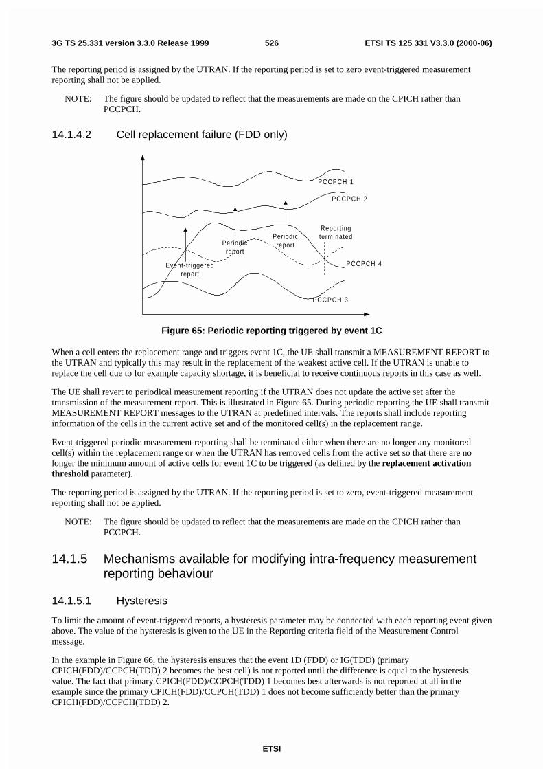
ETSI
ETSI TS 125 331 V3.3.0 (2000-06)5263G TS 25.331 version 3.3.0 Release 1999
The reporting period is assigned by the UTRAN. If the reporting period is set to zero event-triggered measurementreporting shall not be applied.
NOTE: The figure should be updated to reflect that the measurements are made on the CPICH rather thanPCCPCH.
14.1.4.2 Cell replacement failure (FDD only)
PCCPCH 1
Event-tr iggeredreport
Periodicreport
PCCPCH 4
PCCPCH 2
Periodicreport
Report ingterminated
PCCPCH 3
Figure 65: Periodic reporting triggered by event 1C
When a cell enters the replacement range and triggers event 1C, the UE shall transmit a MEASUREMENT REPORT tothe UTRAN and typically this may result in the replacement of the weakest active cell. If the UTRAN is unable toreplace the cell due to for example capacity shortage, it is beneficial to receive continuous reports in this case as well.
The UE shall revert to periodical measurement reporting if the UTRAN does not update the active set after thetransmission of the measurement report. This is illustrated in Figure 65. During periodic reporting the UE shall transmitMEASUREMENT REPORT messages to the UTRAN at predefined intervals. The reports shall include reportinginformation of the cells in the current active set and of the monitored cell(s) in the replacement range.
Event-triggered periodic measurement reporting shall be terminated either when there are no longer any monitoredcell(s) within the replacement range or when the UTRAN has removed cells from the active set so that there are nolonger the minimum amount of active cells for event 1C to be triggered (as defined by the replacement activationthreshold parameter).
The reporting period is assigned by the UTRAN. If the reporting period is set to zero, event-triggered measurementreporting shall not be applied.
NOTE: The figure should be updated to reflect that the measurements are made on the CPICH rather thanPCCPCH.
14.1.5 Mechanisms available for modifying intra-frequency measurementreporting behaviour
14.1.5.1 Hysteresis
To limit the amount of event-triggered reports, a hysteresis parameter may be connected with each reporting event givenabove. The value of the hysteresis is given to the UE in the Reporting criteria field of the Measurement Controlmessage.
In the example in Figure 66, the hysteresis ensures that the event 1D (FDD) or IG(TDD) (primaryCPICH(FDD)/CCPCH(TDD) 2 becomes the best cell) is not reported until the difference is equal to the hysteresisvalue. The fact that primary CPICH(FDD)/CCPCH(TDD) 1 becomes best afterwards is not reported at all in theexample since the primary CPICH(FDD)/CCPCH(TDD) 1 does not become sufficiently better than the primaryCPICH(FDD)/CCPCH(TDD) 2.

ETSI
ETSI TS 125 331 V3.3.0 (2000-06)5273G TS 25.331 version 3.3.0 Release 1999
Hysteresis
Reportingevent 1D
Hysteresis
Measurementquantity
Time
P CCPCH 1
P CCPCH 2
Figure 66: Hysteresis limits the amount of measurement reports
14.1.5.2 Time-to-trigger
To limit the measurement signalling load, a time-to-trigger parameter could be connected with each reporting eventgiven above. The value of the time-to-trigger is given to the UE in the Reporting criteria field of the MeasurementControl message.
The effect of the time-to-trigger is that the report is triggered only after the conditions for the event have existed for thespecified time-to-trigger. In the following FDD example in Figure 67, the use of time-to-trigger means that the event(primary CPICH 3 enters the reporting range) is not reported until is has been within the range for the time given by thetime-to-trigger parameter.
Reportingevent 1A
Measurementquantity
Time
Time-to-trigger
P CPICH 1Reportingrange
P CPICH 2
P CPICH 3
Figure 67: Time-to-trigger limits the amount of measurement reports
In the following TDD example in Figure 68, the use of time-to-trigger means that the event (Timeslot ISCP uponcertain threshold) is not reported until it has been upon the threshold for the time given by the time-to trigger parameter.

ETSI
ETSI TS 125 331 V3.3.0 (2000-06)5283G TS 25.331 version 3.3.0 Release 1999
Time-to-trigger
Timeslot ISCP
ReportingEvent 1J
Time
TS 1
SIRThreshold
Figure 68: Time-to-trigger limits the amount of measurement reports
Note that the time-to-trigger could be combined with hysteresis, i.e. a hysteresis value is added to the measurementquantity before evaluating if the time-to-trigger timer should be started.
14.1.5.3 Cell individual offsets
For each cell that is monitored, an offset can be assigned with inband signalling. The offset can be either positive ornegative. The offset is added to the measurement quantity before the UE evaluates if an event has occurred. The UEreceives the cell individual offsets for each primary CPICH(FDD)/CCPCH(TDD) in the measurement object field of theMEASUREMENT CONTROL message.
For the FDD example, in Figure 69, since an offset is added to primary CPICH 3, it is the dotted curve that is used toevaluate if an event occurs. Hence, this means that measurement reports from UE to UTRAN are triggered whenprimary CPICH plus the corresponding offset, i.e. the dotted curve, leaves and enters the reporting range and when itgets better than primary CPICH 1 (if these events have been ordered by UTRAN). This offset mechanism provides thenetwork with an efficient tool to change the reporting of an individual primary CPICH.
By applying a positive offset, as in Figure 69, the UE will send measurement reports as if the primary CPICH is offset xdB better than what it really is. This could be useful if the operator knows that a specific cell is interesting to monitormore carefully, even though it is not so good for the moment. In the example in Figure 69, the operator might know byexperience that in this area primary CPICH 3 can become good very quickly (e.g. due to street corners) and thereforethat it is worth reporting more intensively. Depending on the implemented handover evaluation algorithm, this mayresult in the cell with primary CPICH 3 being included in the active set earlier than would have been the case withoutthe positive offset.

ETSI
ETSI TS 125 331 V3.3.0 (2000-06)5293G TS 25.331 version 3.3.0 Release 1999
Reportingevent 1A
Reportingevent 1B
Offset forP CPICH 3
Measurementquantity
Time
P CPICH 1
P CPICH 2
P CPICH 3
Reportingrange
Figure 69: A positive offset is applied to primary CPICH 3 before event evaluation in the UE
For the TDD example, in Figure 70, an offset is added to primary CCPCH2, it is the dotted curve that is used toevaluate if the primary CCPCH2 becomes better than primary CCPCH1 (ordered by the UTRAN).
Offset forPCCPCH 2
ReportingEvent 1G
Measurementquantity
Time
PCCPCH 1
Figure 70: A positive offset is applied to primary CCPCH 2
Correspondingly, the operator can choose to apply a negative offset to a primary CCPCH. Then the reporting on thatprimary CCPCH is limited and the corresponding cell may be, at least temporarily excluded from the active set or as atarget cell for handover.
The cell individual offset can be seen as a tool to move the cell border. It is important to note that the offset is addedbefore triggering events, i.e. the offset is added by the UE before evaluating if a measurement report should be sent asopposed to offsets that are applied in the network and used for the actual handover evaluation.
14.1.5.4 Forbid a Primary CPICH to affect the reporting range (FDD only)
The reporting range affects the reporting events 1A and 1B presented above. The reporting range is defined relative tothe best Primary CPICH. However, there could be cases where it is good to forbid a specific Primary CPICH to affectthe reporting range. For example in Figure 71 the network has requested the UE to not let Primary CPICH 3 affect thereporting range. This mechanism could be effective if the operator knows by experience that the quality of PrimaryCPICH 3 is very unstable in a specific area and therefore should not affect the reporting of the other Primary CPICHs.

ETSI
ETSI TS 125 331 V3.3.0 (2000-06)5303G TS 25.331 version 3.3.0 Release 1999
Reportingrange
Measurementquantity
Time
P CPICH 1
P CPICH 2
P CPICH 3
Reportingrange
Figure 71: Primary CPICH 3 is forbidden to affect the reporting range
14.1.6 Report quantities
In the event-triggered measurement reports, mandatory information connected to the events is always reported. Forinstance, at the event "a primary CPICH(FDD)/CCPCH(TDD) enters the reporting range" the corresponding reportidentifies the primary CPICH(FDD)/CCPCH(TDD) that entered the range.
However, besides this mandatory information, UTRAN should be able to optionally require additional measurementinformation in the report to support the radio network functions in UTRAN. Furthermore, it will allow the UTRAN touse the UE as a general tool for radio network optimisation if necessary.
Examples of report quantities that may be appended to the measurement reports are:
NOTE: This list is general and does also apply for reports of other measurement types than the intra-frequencytype. The list is not final.
- Downlink transport channel block error rate.
- Downlink transport channel bit error rate.
- Downlink Ec/I0 on primary CPICH(FDD)/CCPCH(TDD) (e.g. used for initial DL power setting on new radiolinks).
- Time difference between the received primary CPICH(FDD)/CCPCH(TDD) frame-timing from the target celland the earliest received existing DPCH path. [Note: This measurement is identified in 25.211 [2] (denoted Tm inclause 7)].
- UE transmit power.
- UE position (FFS).
- Downlink SIR (RSCP/ISCP) on the traffic channels after RAKE combining (FFS).
14.2 Inter-frequency measurementsThe frequency quality estimate used in events 2a, 2b 2c, 2d and 2e is defined as:
,10)1(10101
HLogMWMLogWLogMQ jBestj
N
ijijjcarrierjcarrier
jA
−⋅⋅−+
⋅⋅=⋅= ∑
=
The variables in the formula are defined as follows:

ETSI
ETSI TS 125 331 V3.3.0 (2000-06)5313G TS 25.331 version 3.3.0 Release 1999
Qfrequency j is the estimated quality of the active set on frequency j
Mfrequency j is the estimated quality of the active set on frequency j.
Mi j is a measurement result of cell i in the active set on frequency j.
NA j is the number of cells in the active set on frequency j.
MBest j is the measurement result of the strongest cell in the active set on frequency j
Wj is a parameter sent from UTRAN to UE and used for frequency j
H is the hysteresis parameter
14.2.1 Inter-frequency reporting events
Within the measurement reporting criteria field in the MEASUREMENT CONTROL message UTRAN notifies the UEwhich events should trigger the UE to send a MEASUREMENT REPORT message. Examples of inter-frequencyreporting events that would be useful for inter-frequency handover evaluation are given below. Note that normally theUEs do not need to report all these events. The listed events are the toolbox from which the UTRAN can choose thereporting events that are needed for the implemented handover evaluation function, or other radio network functions.
All events are evaluated with respect to one of the measurement quantities given in subclause 14.x.x. The measurementobjects are the monitored primary common pilot channels (CPICH) in FDD mode and the monitored primary commoncontrol channels (PCCPCH) in TDD mode. A "non-used frequency" is a frequency that the UE have been ordered tomeasure upon but are not used of the active set. A "used frequency" is a frequency that the UE have been ordered tomeasure upon and is also currently used for the connection.
14.2.1.1 Event 2a: Change of best frequency.
If any of the non- used frequencies quality estimate becomes better than the currently used frequency quality estimate,and event 2a has been ordered by UTRAN then this event shall trigger a report to be sent from the UE when thehysteresis and time to trigger conditions is fulfilled. The corresponding report contains (at least) the best primaryCPICH (FDD) or primary CCPCH (TDD) on the non-used frequency that triggered the event.
14.2.1.2 Event 2b: The estimated quality of the currently used frequency is below acertain threshold and the estimated quality of a non-used frequency is abovea certain threshold.
When this event is ordered by UTRAN in a MEASUREMENT CONTROL message the UE shall send a report whenthe estimated quality of the currently used frequency is below the value of the IE " Threshold used frequency" and theestimated quality of a non-used frequency is above the value of the IE "Threshold non-used frequency" and thehysteresis and time to trigger conditions are fulfilled. The corresponding report contains at least the best primaryCPICH (FDD) or primary CCPCH (TDD) on the non-used frequency that triggered the event.
14.2.1.3 Event 2c: The estimated quality of a non-used frequency is above a certainthreshold
When this event is ordered by UTRAN in a MEASUREMENT CONTROL message the UE shall send a report whenthe estimated quality of a non-used frequency is above the value of the IE "Threshold non-used frequency" and thehysteresis and time to trigger conditions are fulfilled. The corresponding report contains at least the best primaryCPICH (FDD) or primary CCPCH (TDD) on the non-used frequency.
14.2.1.4 Event 2d: The estimated quality of the currently used frequency is below acertain threshold
When this event is ordered by UTRAN in a MEASUREMENT CONTROL message the UE shall send a report whenthe estimated quality of the currently used frequency is below the value of the IE " Threshold used frequency" and thehysteresis and time to trigger conditions are fulfilled. The corresponding report contains at least the best primaryCPICH (FDD) or primary CCPCH (TDD) on the used frequency.

ETSI
ETSI TS 125 331 V3.3.0 (2000-06)5323G TS 25.331 version 3.3.0 Release 1999
14.2.1.5 Event 2e: The estimated quality of a non-used frequency is below a certainthreshold
When this event is ordered by UTRAN in a MEASUREMENT CONTROL message the UE shall send a report whenthe estimated quality of a non-used frequency is below the value of the IE "Threshold non-used frequency" and thehysteresis and time to trigger conditions are fulfilled. The corresponding report contains at least the best primaryCPICH (FDD) or primary CCPCH (TDD) on the non-used frequency.
14.2.1.6 Event 2 f: The estimated quality of the currently used frequency is above acertain threshold
When this event is ordered by UTRAN in a MEASUREMENT CONTROL message the UE shall send a report whenthe estimated quality of the currently used frequency is above the value of the IE " Threshold used frequency" and thehysteresis and time to trigger conditions are fulfilled. The corresponding report contains at least the best primaryCPICH (FDD) or primary CCPCH (TDD) on the used frequency.
14.3 Inter-system measurementsThe estimated quality of the active set in UTRAN in events 3a is defined as:
,10)1(10101
Best
N
iiUTRANUTRAN LogMWMLogWLogMQ
A
⋅⋅−+
⋅⋅=⋅= ∑
=
The variables in the formula are defined as follows:
QUTRAN is the estimated quality of the active set on the currently used UTRAN frequency
MUTRAN is the estimated quality of the active set on currently used UTRAN frequency expressed in another unit.
Mi is a measurement result of cell i in the active set.
NA is the number of cells in the active set.
MBest is the measurement result of the strongest cell in the active set.
W is a parameter sent from UTRAN to UE.
14.3.1 Inter-System reporting events
Within the measurement reporting criteria field in the MEASUREMENT CONTROL message the UTRAN notifies theUE which events should trigger the UE to send a MEASUREMENT REPORT message. Examples of inter-systemreporting events that would be useful for inter-system handover evaluation are given below. Note that normally the UEsdo not need to report all these events. The listed events are the toolbox from which the UTRAN can choose thereporting events that are needed for the implemented handover evaluation function, or other radio network functions.
All events are measured with respect to one of the measurement quantities given in subclause 14.x.x The measurementobjects are the monitored primary common pilot channels (CPICH) in FDD mode and the monitored primary commoncontrol channels (PCCPCH) in TDD mode for UTRAN and objects specific for other systems. A "used UTRANfrequency" is a frequency that the UE have been ordered to measure upon and is also currently used for the connectionto UTRAN. "Other system" is e.g. GSM.
14.3.1.1 Event 3a: The estimated quality of the currently used UTRAN frequency isbelow a certain threshold and the estimated quality of the other system isabove a certain threshold.
When this event is ordered by UTRAN in a MEASUREMENT CONTROL message the UE shall send a report whenthe estimated quality of the currently used frequency is below the value of the IE " Threshold own system" and thehysteresis and time to trigger conditions are fulfilled and the estimated quality of the other system is above the value ofthe IE " Threshold other system" and the hysteresis and time to trigger conditions are fulfilled. The corresponding report

ETSI
ETSI TS 125 331 V3.3.0 (2000-06)5333G TS 25.331 version 3.3.0 Release 1999
contains information specific for the other system and the best primary CPICH (FDD) or primary CCPCH (TDD) on theused frequency.
14.3.1.2 Event 3b: The estimated quality of other system is below a certain threshold
When this event is ordered by UTRAN in a measurement control message the UE shall send a report when theestimated quality of the other system is below the value of the IE " Threshold other system" and the hysteresis and timeto trigger conditions are fulfilled. The corresponding report contains information specific for the other system and thebest primary CPICH (FDD) or primary CCPCH (TDD) on the non-used frequency.
14.3.1.3 Event 3c: The estimated quality of other system is above a certain threshold
When this event is ordered by UTRAN in a measurement control message the UE shall send a report when theestimated quality of the other system is above the value of the IE " Threshold other system" and the hysteresis and timeto trigger conditions are fulfilled. The corresponding report contains information specific for the other system and thebest primary CPICH (FDD) or primary CCPCH (TDD) on the non-used frequency.
14.3.1.4 Event 3d: Change of best cell in other system
If any of the quality estimates for the cells in the other system becomes better than the quality estimate for the currentlybest cell in the other system, and event 3d has been ordered by UTRAN then this event shall trigger a report to be sentfrom the UE when the hysteresis and time to trigger conditions is fulfilled. The corresponding report contains (at least)information the best cell in the other system.
14.4 Traffic Volume Measurements
14.4.1 Traffic Volume Measurement Quantity
For traffic volume measurements in the UE only one quantity is measured. This quantity is RLC buffer payload innumber of bytes. In order to support a large variation of bit rates and RLC buffer size capabilities, a non-linear scaleshould be used [NOTE: details are FFS]. Since, the expected traffic includes both new and retransmitted RLC payloadunits all these should be included in the payload measure. It should also be noted that traffic volume measurements areonly applicable for acknowledged and unacknowledged mode.
According to what is stated in the Measurement Control message, the UE should support measuring of buffer payloadfor a specific RB, RBs multiplexed onto the same Transport channel and the total UE buffer payload (the same as onetransport channel for a UE that uses RACH).
14.4.2 Traffic Volume reporting events
Traffic volume can be reported in two different ways, periodical and event triggered. For periodical reporting the UEsimply measures the number of bytes for the transport channel (i.e. the RLC buffers of the RBs multiplexed onto thattransport channel) stated in the measurement control message and reports the traffic volume at the given time instants.Event triggered reporting is performed when a threshold is exceeded.
The reporting quantities that should be included in the report are stated in the measurement control message. This couldfor example be which RBs or RLC buffers to include when sending the payload to the network.

ETSI
ETSI TS 125 331 V3.3.0 (2000-06)5343G TS 25.331 version 3.3.0 Release 1999
14.4.2.1 Reporting event 4 A: RLC buffer payload exceeds an absolute threshold
Threshold
Payload
Reportingevent 4A
Time
Reportingevent 4A
Figure 72: Event triggered report when RLC buffer payload exceeds a certain threshold
If the monitored payload exceeds an absolute threshold, this is an event that could trigger a report. The correspondingreport contains at least which transport channel triggered the report.
14.4.2.2 Reporting event 4 B: RLC buffer payload becomes smaller than an absolutethreshold
Threshold
Payload
Reportingevent 4B
Time
Reportingevent 4B
Figure 73: Event triggered report when RLC buffer payload becomes smaller than certain threshold
If the monitored payload becomes smaller than an absolute threshold, this is an event that could trigger a report. Thecorresponding report contains at least which transport channel triggered the report.
14.4.3 Traffic volume reporting mechanisms
Traffic volume measurement triggering could be associated with both a time-to-trigger and a pending time after trigger.The time-to-trigger is used to get time domain hysteresis, i.e. the condition must be fulfilled during the time-to-triggertime before a report is sent. Pending time after trigger is used to limit consecutive reports when one traffic volumemeasurement report already has been sent. This is described in detail below.

ETSI
ETSI TS 125 331 V3.3.0 (2000-06)5353G TS 25.331 version 3.3.0 Release 1999
14.4.3.1 Pending time after trigger
This timer is started in the UE when a measurement report has been triggered. The UE is then forbidden to send anynew measurement reports with the same measurement ID during this time period even when the triggering condition isfulfilled again. Instead the UE waits until the timer has suspended. If the payload is still above the threshold when thetimer has expired the UE sends a new measurement report. Otherwise it waits for a new triggering.
Threshold
Payload
Report 1
Time
Report 2
Threshold
Payload
Report 1
Time
No Report
Short pendingtime after trigger
Long pendingtime after trigger
Pending time after trigger Pending time after trigger
Figure 74: Pending time after trigger limits the amount of consecutive measurement reports
Figure 74 shows that by increasing the pending time after trigger a triggered second event does not result in ameasurement report.
14.4.4 Interruption of user data transmission
A UE in CELL_FACH substate may be instructed by the UTRAN to cease transmission of user data on the RACH aftera measurement report has been triggered. Before resuming transmission of user data,
- the UE shall receive from the UTRAN either a message allocating a dedicated physical channel, and make atransition to CELL_DCH state; or
- the UE shall receive an individually assigned measurement control message indicating that interruption of userdata transmission is not be applied.
The transmission of signalling messages on the signalling bearer shall not be interrupted.
14.5 UE internal measurements
14.5.1 UE internal measurement quantities
For UE internal measurements the following measurement quantities exist:
1. UE transmission (Tx) power, for TDD measured on a timeslot basis.
2. UE received signal strength power (RSSI).
3. UE Rx-Tx time difference.

ETSI
ETSI TS 125 331 V3.3.0 (2000-06)5363G TS 25.331 version 3.3.0 Release 1999
14.5.2 UE internal measurement reporting events
In the Measurement reporting criteria field in the Measurement Control messages, the UTRAN notifies the UE of whichevents should trigger a measurement report. UE internal measurement reporting events that can trigger a report aregiven below. The reporting events are marked with vertical arrows in the figures below. All events can be combinedwith time-to-trigger. In that case, the measurement report is only sent if the condition for the event has been fulfilled forthe time given by the time-to-trigger parameter.
NOTE: The reporting events are numbered 6A, 6B, 6C,.. where 6 denotes that the event belongs to the type UEinternal measurements.
14.5.2.1 Reporting event 6A: The UE Tx power becomes larger than an absolutethreshold
When this event is ordered by UTRAN in a measurement control message, the UE shall send a measurement reportwhen the UE transmission power (for TDD within a single TS) becomes larger than a predefined threshold. Thecorresponding report identifies the threshold that was exceeded.
14.5.2.2 Reporting event 6B: The UE Tx power becomes less than an absolutethreshold
When this event is ordered by UTRAN in a measurement control message, the UE shall send a measurement reportwhen the UE transmission power (for TDD within a single TS) becomes less than a predefined threshold. Thecorresponding report identifies the threshold that the UE Tx power went below.
Tx powerthreshold 6A1
Tx powerthreshold 6B1
Tx powerthreshold 6A2
Tx powerthreshold 6B2
Reportingevent 6A
Reportingevent 6B
Reportingevent 6A
Reportingevent 6B
UE Tx power
Time
Figure 75: Event-triggered measurement reports when the UE Tx power becomes larger or less thanabsolute thresholds
14.5.2.3 Reporting event 6C: The UE Tx power reaches its minimum value
When this event is ordered by UTRAN in a measurement control message, the UE shall send a measurement reportwhen the UE Tx power reaches its minimum value, for TDD its minimum value on a single timeslot.

ETSI
ETSI TS 125 331 V3.3.0 (2000-06)5373G TS 25.331 version 3.3.0 Release 1999
MinimumUE Tx power
Reportingevent 6C
UE Tx power
Time
Figure 76: Event-triggered measurement report when the UE Tx power reaches its minimum value
14.5.2.4 Reporting event 6D: The UE Tx power reaches its maximum value
When this event is ordered by UTRAN in a measurement control message, the UE shall send a measurement reportwhen the UE Tx power reaches its maximum value, for TDD its maximum value on a single timeslot.
MaximumUE Tx power
Reportingevent 6D
UE Tx power
Time
Figure 77: Event-triggered report when the UE Tx power reaches its maximum value
14.5.2.5 Reporting event 6E: The UE RSSI reaches the UE's dynamic receiver range
When this event is ordered by UTRAN in a measurement control message, the UE shall send a measurement reportwhen the UE RSSI reaches the UE's dynamic receiver range.
14.5.2.6 Reporting event 6F: The UE Rx-Tx time difference for a RL included in theactive set becomes larger than an absolute threshold
When this event is ordered by UTRAN in a MEASUREMENT CONTROL message, the UE shall send aMEASUREMENT REPORT message when the UE Rx-Tx time difference becomes larger than the threshold defined by theIE "UE Rx-Tx time difference threshold".
14.5.2.7 Reporting event 6G: The UE Rx-Tx time difference for a RL included in theactive set becomes less than an absolute threshold
When this event is ordered by UTRAN in a MEASUREMENT CONTROL message, the UE shall send aMEASUREMENT REPORT when the UE Rx-Tx time difference becomes less than the threshold defined by the IE "UE Rx-Tx time difference threshold".

ETSI
ETSI TS 125 331 V3.3.0 (2000-06)5383G TS 25.331 version 3.3.0 Release 1999
14.6 Dynamic Resource Allocation Control of Uplink DCH (FDDonly)
The network uses this procedure to dynamically control the allocation of resources on an uplink DCH.
This procedure shall be activated in the UE when it has been allocated an uplink DCH with DRAC static informationelements. Such uplink DCHs can be established through RB establishment procedure, RB reconfiguration procedure,RB release procedure or Transport Channel Reconfiguration procedure by setting the DRAC static informationelements to indicate that the DCH is controlled by the DRAC procedure.
The UE shall periodically listen to the SIB 10 of each cell in its Active Set. The scheduling information of SIB10 andthe SCCPCH info on which the SIB10 is transmitted are provided to the UE when the DCH is set up and when a cell isadded in its active set. In case several SIB10 messages from different cells are scheduled at the same time, the UE shallonly listen to the SIB10 broadcast in the cell of its Active Set having the best CPICH measurements.
Upon reception of a SYSTEM INFORMATION message comprising a SIB10,the UE shall:
1. Determine and store the most stringent DRAC parameters from the last received values from each cell of itsactive set (i.e. select the lowest product ptr*maximum bit rate corresponding to its DRAC class identity)
2. Determine the allowed subset of TFCS according to the selected maximum bit rate value, and store it for laterusage.The allowed subset of TFCS are the ones of the TFCS for which the sum of bit rates of the DCH controlled byDRAC is lower than Maximum Bit Rate IE, i.e.
∑ <DRACby controlled DCHi
/ RateMaximumBitTTITBSsize ii
After the first SIB10 has been received, the UE shall start the following process:
1. At the start of the next TTI, the UE shall randomly select p " [0,1].
2. If p < ptr, the UE shall transmit on the DCH controlled by DRAC during Tvalidity frames using the last storedallowed subset of TFCS and comes back to step 1, otherwise the UE shall stop transmission on these DCHduring Tretry frames and then comes back to step 1.
Transmission time validity (Tvalidity) and Time duration before retry (Tretry) are indicated to the UE at the establishmentof a DCH controlled by this procedure and may be changed through RB or transport channel reconfiguration. The UEshall always use the latest received DRAC static parameters.
A UE which supports the simultaneous reception of one SCCPCH and one DPCH shall support the DRAC procedure.
14.7 Downlink power control
14.7.1 Generalities
This function is implemented in the UE in order to set the SIR target value on each CCTrCH used for the downlinkpower control. This SIR value shall be adjusted according to an autonomous function in the UE in order to achieve thesame measured quality as the quality target set by UTRAN. The quality target is set as the transport channel BLERvalue for each transport channel as signalled by UTRAN. For CPCH the quality target is set as the BER of the DLDPCCH as signalled by UTRAN.
When transport channel BLER is used the UE shall run a quality target control loop such that the quality requirement ismet for each transport channel, which has been assigned a BLER target.
When DL DPCCH BER is used the UE shall run a quality target control loop such that the quality requirement is metfor each CPCH transport channel, which has been assigned a DL DPCCH BER target.
The UE shall set the SIR target when the physical channel has been set up or reconfigured. It shall not increase the SIRtarget value before the power control has converged on the current value. The UE may estimate whether the powercontrol has converged on the current value, by comparing the averaged measured SIR to the SIR target value.

ETSI
ETSI TS 125 331 V3.3.0 (2000-06)5393G TS 25.331 version 3.3.0 Release 1999
If the UE has received a DL outer loop control message from UTRAN indicating that the SIR target value shall not beincreased above the current value, it shall record the current value as the maximum allowed value for the power controlfunction, until it receives a new DL outer loop control message from UTRAN indicating that the restriction is removed.
14.7.2 Downlink power control in compressed mode
In compressed mode, the target SIR needs to be changed during compressed frames and one frame after compressedframes (recovery frame), compared to normal mode. For this purpose, four values DeltaSIR1, DeltaSIRafter1,DeltaSIR2 and DeltaSIRafter2 are signalled by the UTRAN to the UE (see section 10.2.9).
For each frame, the target SIR offset during compressed mode, compared to normal mode is:
∆SIR = max (∆SIR1_compression, … , ∆SIRn_compression) + ∆SIR_coding
where n is the number of TTI lengths for all TrChs of the CCTrCh, Fi is the length in number of frames of the i-th TTI
and where ∆SIR_coding fulfils:
- ∆SIR_coding= DeltaSIR1 for compressed frames corresponding to the first transmission gap in the transmissiongap pattern.
- ∆SIR_coding= DeltaSIRafter1 for recovery frames corresponding to the first transmission gap in thetransmission gap pattern.
- ∆SIR_coding= DeltaSIR2 for compressed frames corresponding to the second transmission gap in thetransmission gap pattern.
- ∆SIR_coding= DeltaSIRafter2 for recovery frames corresponding to the second transmission gap in thetransmission gap pattern.
- ∆SIR_coding= 0 otherwise.
and ∆SIRi_compression is defined by :
- If the frames are compressed by reducing the spreading factor by 2 ("Compressed mode method" IE is equal to"SF/2"):
- ∆SIRi_compression= 3 dB for each compressed frame, where TGL is the gap length in number of slots(either from one gap or a sum of gaps) in the frame.
- ∆SIRi_compression= 0 otherwise.
- If the frames are compressed by puncturing ("Compressed mode method" IE is equal to "puncturing"):
- ∆SIRi_compression= 10 log (15*Fi / (15*Fi - TGLi)) if there is a transmission gap within the current TTI oflength Fi frames, where TGLi is the gap length in number of slots (either from one gap or a sum of gaps) inthe current TTI of length Fi frames.
- ∆SIRi_compression= 0 otherwise.
- If the frames are compressed by upper layer scheduling ("Compressed mode method" IE is equal to "upper layerscheduling"):
- ∆SIRi_compression= 0 for all frames.
In the particular case where a transmission gap overlaps two frames (double-frame method), the second compressedframe (with the second part of the transmission gap) must be considered as the recovery frame (∆SIR_coding =DeltaSIRafter1 or ∆SIR_coding = DeltaSIRafter2). Thus, in this case, the first frame following the two consecutivecompressed frames is not considered as a recovery frame (∆SIR_coding=0).
Several compressed mode patterns applying to the same frames should be avoided as much as possible.
In particular; several simultaneous patterns by puncturing applying to the same frames shall be considered as a protocolerror by the UE. The handling of this error is described in the procedure descriptions in clause 8
ETSI
ETSI TS 125 331 V3.3.0 (2000-06)5403G TS 25.331 version 3.3.0 Release 1999
In case a frame or TTI is simultaneously compressed by puncturing and by reduction of the spreading factor, or in casea frame is simultaneously a compressed frame in one pattern and a recovery frame in another pattern, all offsets must beadded and the total target SIR offset is applied to the frame.
14.8 Calculated Transport Format CombinationThe Calculated Transport Format Combination (CTFC) is a tool for efficient signalling of transport formatcombinations.
Let I be the number of transport channels that are included in the transport format combination. Each transport channelTrCHi, i = 1, 2, …, I, has Li transport formats, i.e. the transport format indicator TFIi can take Li values,
}1,...,2,1,0{ −∈ ii LTFI .
Define ∏−
=
=1
0
i
jji LP , where i = 1, 2, …, I, and L0 = 1.
Let TFC(TFI1, TFI2, …, TFII) be the transport format combination for which TrCH1 has transport format TFI1, TrCH2has transport format TFI2, etc. The corresponding CTFC(TFI1, TFI2, …, TFII) is then computed as:
i
I
iiI PTFITFITFITFICTFC ⋅= ∑
=121 ),,,( � .
For downlink common CH, "TrCHi" is numbered with ascending integer numbers starting from 1 in the order listed in aSYSTEM INFORMATION message.
In all other cases, for each separate TFCI field, "TrCHi" is numbered with ascending integer numbers starting from 1 inthe ascending order of transport channel identities of the channels mapped to that TFCI field.
14.9 UE autonomous update of active set on non-usedfrequency (FDD only)
Within the measurement reporting criteria field in the MEASUREMENT CONTROL message the UTRAN notifies theUE which events should trigger a measurement report. For inter frequency measurements it is possible to specify intra-frequency measurements reporting events for support of maintenance of a active set associated with a non-usedfrequency, a "virtual active set". A "non-used frequency" is a frequency that the UE has been ordered to measure uponbut are not used by the active set. A "used frequency" is a frequency that the UE has been ordered to measure upon andis also currently used for the connection.
The autonomous update is controlled by the IE "UE autonomous update mode" that can be set to the following values.
- On: Do the autonomous updates of the "virtual active set" according to the described rules below and also reportthe events that trigger the update of the "virtual active set".
- On with no reporting: Do the autonomous updates of the "virtual active set" according to the described rulesbelow.
- Off: Only report the events and do no updates of the "virtual active set" unless ordered to do so by the IE " Inter-frequency set update".
If the IE "UE autonomous update mode" is set to "on" or "on with no reporting" the UE shall evaluate the followingintra-frequency events and update the "virtual active set" associated with the frequency measured upon, according to thefollowing rules:
- Event 1a shall make the UE add the primary CPICH that enters the reporting range to the "virtual active set".
- Event 1b shall make the UE remove a primary CPICH that leaves the reporting range from the "virtual activeset".

ETSI
ETSI TS 125 331 V3.3.0 (2000-06)5413G TS 25.331 version 3.3.0 Release 1999
- Event 1c shall make the UE replace a active primary CPICH in the "virtual active set" with a non-active primaryCPICH that have become better than the active primary CPICH.
14.10 Provision and reception of RRC information betweennetwork nodes
14.10.1 RRC Initialisation Information, source RNC to target RNC
When relocation of SRNS is decided to be executed, the RRC shall build the state information, which contains theRRC, RLC and MAC related RRC message information elements, which currently specify the state of the RRCincluding the radio bearer and transport channel configuration. This "RRC initialisation information, source RNC totarget RNC" shall be sent by the source RNC to the target RNC to enable transparent relocation of the RRC and lowerlayer protocols. Correspondingly, the RRC in the target RNC shall receive the "RRC initialisation information, sourceRNC to target RNC" and update its state parameters accordingly to facilitate a transparent relocation of SRNS for theUE.

ETSI
ETSI TS 125 331 V3.3.0 (2000-06)5423G TS 25.331 version 3.3.0 Release 1999
Information Element/GroupName
Need Multi Type and reference Semanticsdescription
Non RRC IEsState of RRC MP Enumerated
(CELL_DCH,CELL_FACH,CELL_PCH, URA_PCH)
State of RRC procedure MP Enumerated (await noRRC message, awaitRRC Connection Re-establishmentComplete, await RBSetup Complete, awaitRB ReconfigurationComplete, await RBRelease Complete,await Transport CHReconfigurationComplete, awaitPhysical CHReconfigurationComplete, await ActiveSet Update Complete,await HandoverComplete, others)
Ciphering related informationCiphering status MP Enumerated(Not
started, Started)Calculation time for cipheringrelated information
CVCiphering
Time when thecipheringinformation of themessage werecalculated, relativeto a cell of thetarget RNC
>Cell Identity MP Cell Identity 10.3.2.2 Identity of one ofthe cells under thetarget RNC andincluded in theactive set of thecurrent call
>SFN MP Integer(0..4095)Ciphering info per radio bearer OP 1 to
<maxRB>
>RB identity MP RB identity10.3.4.13
>Downlink HFN MP Hyperframe number10.3.3.13
>Uplink HFN MP Hyperframe number10.3.3.13
Integrity protection relatedinformation
Integrity protection status MP Enumerated(Notstarted, Started)
Integrity protection failure count MP Integer(0..N316)Signalling radio bearer specificintegrity protection information
CV IP 4 to<maxSRBsetup>
Status informationfor RB#0-4 in thatorder
> Uplink HFN MP Hyper frame number10.3.3.13
> Downlink HFN MP Hyper frame number10.3.3.13
> Uplink RRC Message sequencenumber
MP Integer (0..15)
> Downlink RRC Messagesequence number
MP Integer (0..15)

ETSI
ETSI TS 125 331 V3.3.0 (2000-06)5433G TS 25.331 version 3.3.0 Release 1999
Implementation specificparameters
OP Bitstring (1..512)
RRC IEsUE Information elements
U-RNTI MP U-RNTI10.3.3.45
C-RNTI OP C-RNTI10.3.3.8
UE radio access Capability MP UE radio accesscapability10.3.3.40
Other Information elementsInter System message (intersystem classmark)
OP Inter-system message10.8.6
UTRAN Mobility Informationelements
URA Identifier OP URA identity10.3.2.6
CN Information ElementsCN common GSM-MAP NASsystem information
MP NAS systeminformation (GSM-MAP)10.3.1.9
CN domain related information OP 1 to<MaxCNdomains>
CN relatedinformation to beprovided for eachCN domain
>CN domain identity MP>CN domain specific GSM-MAPNAS system info
MP NAS systeminformation (GSM-MAP)10.3.1.9
Measurement RelatedInformation elements
For each ongoing measurementreporting
OP 1 to<MaxNoOfMeas>
>Measurement Identity Number MP Measurement identitynumber10.3.7.73
>Measurement Command MP Measurementcommand10.3.7.71
>Measurement Type CV Setup Measurement type10.3.7.75
>Measurement Reporting Mode OP Measurement reportingmode10.3.7.74
>Additional Measurements list OP Additionalmeasurements list10.3.7.1
>CHOICE Measurement OP>>Intra-frequency>>>Intra-frequency cell info OP Intra-frequency cell info
list10.3.7.33
>>>Intra-frequency measurementquantity
OP Intra-frequencymeasurement quantity10.3.7.38
>>>Intra-frequency reportingquantity
OP Intra-frequencyreporting quantity10.3.7.41
>>>Reporting cell status OP Reporting cell status10.3.7.86
>>>Measurement validity OP Measurement validity10.3.7.76

ETSI
ETSI TS 125 331 V3.3.0 (2000-06)5443G TS 25.331 version 3.3.0 Release 1999
>>>CHOICE report criteria OP>>>>Intra-frequencymeasurementreporting criteria
Intra-frequencymeasurement reportingcriteria10.3.7.39
>>>>Periodical reporting Periodical reportingcriteria10.3.7.78
>>>>No reporting NULL>>Inter-frequency>>>Inter-frequency cell info OP Inter-frequency cell info
list10.3.7.13
>>>Inter-frequency measurementquantity
OP Inter-frequencymeasurement quantity10.3.7.18
>>>Inter-frequency reportingquantity
OP Inter-frequencyreporting quantity10.3.7.21
>>>Reporting cell status OP Reporting cell status10.3.7.86
>>>Measurement validity OP Measurement validity10.3.7.76
>>>CHOICE report criteria OP>>>>Inter-frequencymeasurementreporting criteria
Inter-frequencymeasurement reportingcriteria10.3.7.19
>>>>Periodical reporting Periodical reportingcriteria10.3.7.78
>>>>No reporting NULL>>Inter-system>>>Inter-system cell info OP Inter-system cell info
list10.3.7.23
>>>Inter-system measurementquantity
OP Inter-systemmeasurement quantity10.3.7.29
>>>Inter-system reporting quantity OP Inter-system reportingquantity10.3.7.32
>>>Reporting cell status OP Reporting cell status10.3.7.86
>>>Measurement validity OP Measurement validity10.3.7.76
>>>CHOICE report criteria OP>>>>Inter-system measurementreporting criteria
Inter-systemmeasurement reportingcriteria10.3.7.30
>>>>Periodical reporting Periodical reportingcriteria10.3.7.78
>>>>No reporting NULL>>Traffic Volume>>>Traffic volume measurementObject
OP Traffic volumemeasurement object10.3.7.95
>>>Traffic volume measurementquantity
OP Traffic volumemeasurement quantity10.3.7.96
>>>Traffic volume reportingquantity
OP Traffic volume reportingquantity10.3.7.99
>>>CHOICE report criteria OP

ETSI
ETSI TS 125 331 V3.3.0 (2000-06)5453G TS 25.331 version 3.3.0 Release 1999
>>>>Traffic volume measurementreporting criteria
Traffic volumemeasurement reportingcriteria10.3.7.97
>>>>Periodical reporting Periodical reportingcriteria10.3.7.78
>>>>No reporting NULL>>Quality>>>Quality measurementObject
OP Quality measurementobject
>>>Quality measurementquantity
OP Quality measurementquantity
>>>Quality reporting quantity OP Quality reportingquantity10.3.7.84
>>>CHOICE report criteria OP>>>>Quality measurementreporting criteria
Quality measurementreporting criteria10.3.7.83
>>>>Periodical reporting Periodical reportingcriteria10.3.7.78
>>>>No reporting NULL>>UE internal>>>UE internal measurementquantity
OP UE internalmeasurement quantity10.3.7.104
>>>UE internal reporting quantity OP UE internal reportingquantity10.3.7.107
>>>CHOICE report criteria OP>>>>UE internal measurementreporting criteria
UE internalmeasurement reportingcriteria10.3.7.105
>>>>Periodical reporting Periodical reportingcriteria10.3.7.78
>>>>No reporting NULLRadio Bearer Information
ElementsSignalling radio bearer information MP 4 to
<maxSRBsetup>
For each signallingradio bearer
>RB identity MP RB identity10.3.4.13
>RLC info MP RLC info10.3.4.20
>RB mapping info MP RB mapping info10.3.4.18
RAB information OP 1 to<maxRABsetup>
Information for eachRAB
>RAB info MP RAB info10.3.4.8
>For each Radio Bearer OP 1 to<maxRB>
Information for eachradio bearerbelonging to thisRAB
>>RB Identity MP RB identity10.3.4.13
>>RLC Info MP RLC info10.3.4.20

ETSI
ETSI TS 125 331 V3.3.0 (2000-06)5463G TS 25.331 version 3.3.0 Release 1999
>>PDCP Info OP PDCP info10.3.4.2
Absent if PDCP isnot configured forRB
>>PDCP SN Info CV PDCP PDCP SN info10.3.4.3
>>RB mapping info MP RB mapping info10.3.4.18
Transport Channel InformationElements
TFCS (UL DCHs) OP Transport formatcombination set10.3.5.20
TFCS (DL DCHs) OP Transport formatcombination set10.3.5.20
TFC subset (UL DCHs) OP Transport formatcombination subset10.3.5.22
TFCS (USCHs) OP Transport formatcombination set10.3.5.20
TFCS (DSCHs) OP Transport formatcombination set10.3.5.20
TFC subset (USCHs) OP Transport formatcombination subset10.3.5.22
Uplink transport channelsFor each uplink transport channel OP 1 to
<MaxTrCH>
>Transport channel identity MP Transport channelidentity10.3.5.18
>TFS MP Transport format set10.3.5.23
Downlink transport channelsFor each downlink transportchannel
OP 1 to<MaxTrCH>
>Transport channel identity MP Transport channelidentity10.3.5.18
>TFS MP Transport format set10.3.5.23
Measurement report OP MEASUREMENTREPORT10.2.17
Multi Bound ExplanationMaxNoOfMeas Maximum number of active measurements, upper
limit 16

ETSI
ETSI TS 125 331 V3.3.0 (2000-06)5473G TS 25.331 version 3.3.0 Release 1999
Condition ExplanationSetup The IE is mandatory when the IE Measurement
command has the value "Setup", otherwise the IE isnot needed.
Ciphering The IE is mandatory when the IE Ciphering Statushas the value "started" and the ciphering countersneed not be reinitialised, otherwise the IE is notneeded.
IP The IE is mandatory when the IE Integrity protectionstatus has the value "started" and the cipheringcounters need not be reinitialised, otherwise the IE isnot needed.
PDCP The IE is mandatory when the PDCP Info IE ispresent, otherwise the IE is not needed.
14.10.2 RRC initialisation information, source system to target RNC
Information Element/Groupname
Need Multi Type and reference Semanticsdescription
CHOICE RRC message MP>UE CAPABILITYINFORMATION
UE CAPABILITYINFORMATION10.2.60
NOTE: is assumedto containHFNs aswell. Atleast onesparevalue withcriticality:reject isneeded.
NOTE: Other information, such as a list of predefined configurations in the source system, is FFS.
14.10.3 RRC information, target RNC to source system
There are 2 possible cases for RNC relocation:
1. The UE is already under control of target RNC; and
2. The SRNC Relocation with Hard Handover (UE still under control of SRNC), but UE is moving to a locationcontrolled by the target RNC (based on measurement information).
In case 1 the relocation is transparent to the UE and there is no "reverse" direction container. The SRNC just assigns the'serving' function to the target RNC which then becomes the Serving RNC.
In case 2 the relocation is initiated by SRNC which also provides the RRC Initialization Information to the target RNC.Base on this information, the target RNC prepares the Hard Handover Message ( "Physical channel reconfiguration"(subclause 8.2.6), "radio bearer establishment" (subclause 8.2.1), "Radio bearer reconfiguration" (subclause 8.2.2),"Radio bearer release" (subclause 8.2.3) or "Transport channel reconfiguration" (subclause 8.2.4). In addition to this itmay be "Handover To Utran Command" fromanother system e.g. GSM. One of these messages is transmitted using atransparent target RNC to source system direction RANAP container to the SRNC. This message is labeled as XXX.
The source RNC then transmits the Handover Message to the UE which then performs the handover.
In the successful case, the UE transmits an XXX COMPLETE message, using the new configuration, to the target RNC.
In case of failure, the UE transmits an XXX FAILURE, using the old configuration, to the source RNC and the RRCcontext remains unchanged (has to be confirmed and checked with the SRNS relocation procedure).

ETSI
ETSI TS 125 331 V3.3.0 (2000-06)5483G TS 25.331 version 3.3.0 Release 1999
Information Element/Groupname
Need Multi Type and reference Semanticsdescription
CHOICE RRC message MP> RADIO BEARER SETUP RADIO BEARER
SETUP10.2.31
> RADIO BEARERRECONFIGURATION
RADIO BEARERRECONFIGURATION10.2.25
>RADIO BEARER RELEASE RADIO BEARERRELEASE10.2.28
> TRANSPORT CHANNELRECONFIGURATION
TRANSPORTCHANNELRECONFIGURATION10.2.54
> PHYSICAL CHANNELRECONFIGURATION
PHYSICAL CHANNELRECONFIGURATION10.2.20
> HANDOVER TO UTRANCOMMAND
HANDOVER TOUTRAN COMMAND10.2.10
14.11 Versatile Channel Assignment Mode (VCAM) mapping rule(FDD only)
When Versatile Channel Assignment Method (VCAM) is used in the CPCH procedure, the following mapping rulesshall be used to specify one PCPCH.
If the number of PCPCHs is less than or equal to 16, there is a one to one mapping between the CA index and thePCPCH index. Thus a suitable AP signature (and/or AP sub-channel) number is transmitted for the required spreadingfactor based on the broadcast system information, and the assigned PCPCH index (having the requested spreadingfactor) corresponds to the received CA index.
When the number of PCPCHs is greater than 16, a combination of an AP signature (and/or AP sub-channel) numberand a CA signature number specifies one PCPCH as follows:
In VCAM mapping rule, a combination of an AP signature (and/or AP sub-channel) number and a CA signature numberspecifies one PCPCH. In a CPCH set, there are K available PCPCHs which are numbered k=0,1,…, K-1, and there are Ravailable Minimum Spreading Factor Ar, r=0,1,…,R-1, that a UE can request and use. The maximum available numberof PCPCHs and the number of available AP signatures (and/or AP sub-channels) for Ar are denoted as P0r and Sr,respectively, for r=0,1,…,R-1. Let Pr be equal to 16 if P0r is less than 16 and to P0r otherwise. Tr represents the numberof CA signatures for Ar which are needed for specifying PCPCH. The default value of Tr is 16.
Sr always satisfies }:min{ rrr PTssS ≥×≥ . :
The list of available AP signatures (and/or AP sub-channels) for each Ar is renumbered from signature index 0 tosignature index Sr -1, starting with the lowest AP signature (and/or AP sub-channel) number, and continuing insequence, in the order of increasing signature numbers.
Then for given AP signature (and/or AP sub-channel) number and CA signature number, the number k that signifies theassigned PCPCH is obtained as:
,mod}]mod){[( rrr PSjSnik ++=
where i (i=0,1,…,Sr-1) is the AP signature (and/or AP sub-channel) index for Ar, j (j=0,1,…,min(Pr,Tr)-1) is the CAsignature number for Ar and n is a nonnegative integer which satisfies
}0mod)(:min{ where)1( ==+<+≤ rrrrrrrr PSmmMSMnSjiSMn .
An example of the above mapping rule is shown in subclause 18.1.

ETSI
ETSI TS 125 331 V3.3.0 (2000-06)5493G TS 25.331 version 3.3.0 Release 1999
14.12 LCS measurements
14.13 RRC information transferred between UE and othersystems
This subclause specifies RRC information that is exchanged between other systems and the UE. This information istransferred via another RAT in accordance with the specifications applicable for those systems. This subclause specifiesthe UTRAN RRC information applicable for the different information flows.
14.13.1 RRC information, another RAT to UE
14.13.1.1 Pre-defined configuration information
Another system may provide the UE with one or more pre- defined UTRAN configurations, comprising of radio bearer,transport channel and physical channel parameters. The UE shall store the information, and use it upon handover toUTRAN if requested to do so within the HANDOVER TO UTRAN COMMAND message. The pre- definedconfiguration information includes the following RRC information.
Information Element/Groupname
Need Multi Type andreference
Semantics description
RB information elementsPredefined radio configurations 1 to
<maxPredefConfigCount>
>Predefined configurationidentity
MP Predefinedconfigurationidentity10.3.4.5
>Predefined configuration valuetag
OP Predefinedconfigurationvalue tag10.3.4.6
UE information elementsRe-establishment timer MP Re-
establishment timer10.3.3.30
RB information elements>Predefined RB configuration MP Predefined
RBconfiguration10.3.4.7
TrCH Information Elements>Predefined TrCH configuration MP Predefined
TrCHconfiguration10.3.5.9
PhyCH Information Elements>Predefined PhCH configuration MP Predefined
PhyCHconfiguration10.3.6.48
Multi Bound ExplanationMaxPredefConfigCount Maximum number of predefined configurations

ETSI
ETSI TS 125 331 V3.3.0 (2000-06)5503G TS 25.331 version 3.3.0 Release 1999
14.13.2 RRC information, UE to another RAT
14.13.2.1 UE capability information
Upon receiving a UE information request from another system, the UE shall indicate the requested capabilities. The UEcapability information includes the following RRC information.
Information Element/Groupname
Need Multi Type andreference
Semantics description
UE information elementsUE radio access capability OP UE radio
accesscapability10.3.3.40
14.13.2.2 UE security information
Upon receiving a UE information request from another system, the UE shall indicate the requested security information.The UE security information includes the following RRC information.
Information Element/Groupname
Need Multi Type andreference
Semantics description
UE information elementsSTART list MP 1 to
<MaxCNdomains>
START [TS 33.102] values forall CN domains
>CN domain identity MP CN domainidentity10.3.1.1
>START MP Hyper framenumber10.3.3.13
START values to be used inthis CN domain.
14.13.2.3 Pre-defined configuration status information
Another system may provide the UE with one or more pre- defined UTRAN configurations, comprising of radio bearer,transport channel and physical channel parameters. If requested, the UE shall indicate the configurations it has stored.The pre-defined configuration status information should include the following RRC information.
Information Element/Groupname
Need Multi Type andreference
Semantics description
RB information elementsPredefined configurations 1 to
<maxPredefConfigCount>
The list is in order ofpreconfiguration identity
>Predefined configuration valuetag
OP Predefinedconfigurationvalue tag10.3.4.6
The UE shall include the valuetag if it has stored theconcerned configuration
Multi Bound ExplanationMaxPredefConfigCount Maximum number of predefined configurations
15 Primitives between RRC and upper layersVoid.

ETSI
ETSI TS 125 331 V3.3.0 (2000-06)5513G TS 25.331 version 3.3.0 Release 1999
16 Handling of unknown, unforeseen and erroneousprotocol data
16.1 GeneralThis subclause specifies procedures for the handling of unknown, unforeseen, and erroneous protocol data by thereceiving entity. These procedures are called "error handling procedures", but in addition to provide recoverymechanisms for error situations they define a compatibility mechanism for future extensions of the protocol.
The error handling procedures specified in this subclause shall apply to all RRC messages. When there is a specifichandling for messages received on different logical channels this is specified.
When the UE receives an RRC message, it shall set the variable PROTOCOL_ERROR_REJECT to FALSE and thenperform the checks in the order as defined below.
The procedures specified in clause 8 are applied only for the messages passing the checks as defined below, exceptwhen procedure specific handling is used to recover from the error.
16.2 ASN.1 violation or encoding errorIf the UE receives a message on the DCCH for which the encoded message does not result in a valid abstract syntaxvalue, it shall perform the following:
- Set the variable PROTOCOL_ERROR_REJECT to TRUE.
- Transmit an RRC STATUS message on the uplink DCCH. The IE "Protocol error information" shall contain anIE "Protocol error cause" set to "ASN.1 violation or encoding error".
- When the transmission of the RRC STATUS message has been confirmed by RLC, the UE shall resume normaloperation as if the invalid message has not been received.
If the UE receives a message on the BCCH, PCCH or CCCH for which the encoded message does not result in a validabstract syntax value, it shall ignore the message.
16.3 Unknown or unforeseen message typeIf a UE receives an RRC message on the DCCH with a message type reserved for future extension it shall:
- Set the variable PROTOCOL_ERROR_REJECT to TRUE.
- Transmit an RRC STATUS message on the uplink DCCH. The IE "Protocol error information" shall contain anIE "Protocol error cause" set to "Message type non-existent or not implemented".
- When the transmission of the RRC STATUS message has been confirmed by RLC, the UE shall resume normaloperation as if the invalid message has not been received.
If the UE receives a message on the BCCH, PCCH or CCCH with a message type reserved for future extension it shallignore the message.
16.4 Unknown or unforeseen information element value,mandatory information element
If the UE receives an RRC message on the DCCH, or addressed to the UE on the CCCH, with a mandatory IE having avalue, including choice, reserved for future extension the UE shall
- If criticality of the IE is defined as "Ignore" and if a default value of the IE is defined, treat the rest of themessage using the default value of the IE.

ETSI
ETSI TS 125 331 V3.3.0 (2000-06)5523G TS 25.331 version 3.3.0 Release 1999
- If criticality of the IE is defined as "Reject" or no default value of the IE is defined:
- Set the variable PROTOCOL_ERROR_REJECT to TRUE.
- Set the IE "Protocol error cause" in the variable PROTOCOL_ERROR_INFORMATION to "Informationelement value not comprehended".
- Perform procedure specific error handling according to clause 8.
If the UE receives an RRC message on the BCCH or PCCH with a mandatory IE having a value reserved for futureextension it shall
- If criticality of the IE is defined as "Ignore" and if a default value of the IE is defined, treat the rest of themessage using the default value of the IE.
- If criticality of the IE is defined as "Reject" or no default value of the IE is defined, ignore the message.
16.5 Conditional information element errorIf the UE receives an RRC message on the DCCH, BCCH, PCCH, or addressed to the UE on the CCCH, for which thespecified conditions for absence of a conditional IE are met and that IE is present, the UE shall:
- Ignore the IE.
- Treat the rest of the message as if the IE was not present.
If the UE receives an RRC message on the DCCH, or addressed to the UE on the CCCH, for which the specifiedconditions for presence of a conditional IE are met and that IE is absent, the UE shall:
- Set the variable PROTOCOL_ERROR_REJECT to TRUE.
- Set the IE "Protocol error cause" in the variable PROTOCOL_ERROR_INFORMATION to "Conditionalinformation element error".
- Perform procedure specific error handling according to clause 8.
If the UE receives an RRC message on the BCCH or PCCH for which the specified conditions for presence of aconditional IE are met and that IE is absent, the UE shall ignore the message.
16.6 Unknown or unforeseen information element value,conditional information element
If the UE receives an RRC message on the DCCH, or addressed to the UE on the CCCH, for which the specifiedconditions for presence of a conditional IE are met, that IE is present, and that IE has a value, including choice, reservedfor future extension, the UE shall
- If criticality of the IE is defined as "Ignore" and if a default value of the IE is defined, treat the rest of themessage using the default value of the IE.
- If criticality of the IE is defined as "Reject" or no default value of the IE is defined:
- Set the variable PROTOCOL_ERROR_REJECT to TRUE.
- Set the IE "Protocol error cause" in the variable PROTOCOL_ERROR_INFORMATION to "Informationelement value not comprehended".
- Perform procedure specific error handling according to clause 8.
If the UE receives an RRC message on the BCCH or PCCH for which the specified conditions for presence of aconditional IE are met, that IE is present, and that IE has a value, including choice, reserved for future extension, theUE shall

ETSI
ETSI TS 125 331 V3.3.0 (2000-06)5533G TS 25.331 version 3.3.0 Release 1999
- If criticality of the IE is defined as "Ignore" and if a default value of the IE is defined, treat the rest of themessage using the default value of the IE.
- If criticality of the IE is defined as "Reject" or no default value of the IE is defined, ignore the message.
16.7 Unknown or unforeseen information element value, optionalinformation element
If the UE receives an RRC message on the DCCH, or addressed to the UE on the CCCH, with an optional IE having avalue, including choice, reserved for future extension and the criticality for that IE is specified as "ignore", it shall:
- Ignore the value of the IE.
- Treat the rest of the message as if the IE was not present.
If the UE receives an RRC message on the DCCH, or addressed to the UE on the CCCH, with an optional IE having avalue, including choice, reserved for future extension and the criticality for that IE is specified as "reject", it shall:
- Set the variable PROTOCOL_ERROR_REJECT to TRUE.
- Set the IE "Protocol error cause" in the variable PROTOCOL_ERROR_INFORMATION to "Informationelement value not comprehended".
- Perform procedure specific error handling according to clause 8.
If the UE receives an RRC message on the BCCH or PCCH with an optional IE having a value, including choice,reserved for future extension it shall:
- Ignore the value of the IE.
- Treat the rest of the message as if the IE was not present.
16.8 Unexpected message extensionIf the UE receives a message on the DCCH, or addressed to the UE on the CCCH, containing at least one informationelement in an extension for which a content is not defined, and therefore not expected, the UE shall check the criticalityof that extension, if defined.
- If the criticality for the extension is defined and is set to "Ignore", the UE shall ignore the content of theextension and the message contents after the extension, but treat the parts of the message up to the extensionnormally.
- If the criticality for the extension is defined and is set to "Reject", or if the criticality is not defined, the UE shall:
- Set the variable PROTOCOL_ERROR_REJECT to TRUE.
- Set the IE "Protocol error cause" in the variable PROTOCOL_ERROR_INFORMATION to "Messageextension not comprehended".
- Perform procedure specific error handling according to clause 8.
If the UE receives a message on the BCCH or PCCH, containing at least one information element in an extension forwhich a content is not defined, and therefore not expected, the UE shall check the criticality of that extension, ifdefined.
- If the criticality for the extension is defined and is set to "Ignore", the UE shall ignore the content of theextension and the message contents after the extension, but treat the parts of the message up to the extensionnormally.
- If the criticality for the extension is defined and is set to "Reject", or if the criticality is not defined, the UE shallignore the message.
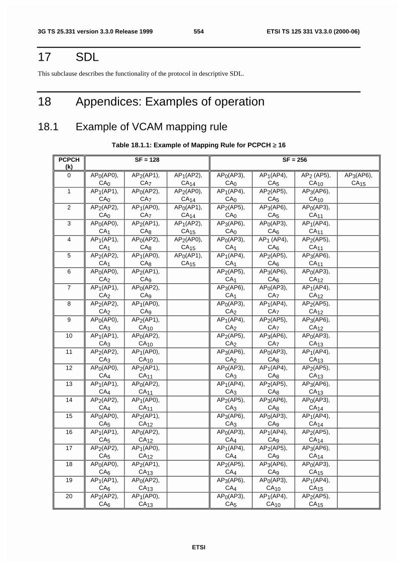
ETSI
ETSI TS 125 331 V3.3.0 (2000-06)5543G TS 25.331 version 3.3.0 Release 1999
17 SDLThis subclause describes the functionality of the protocol in descriptive SDL.
18 Appendices: Examples of operation
18.1 Example of VCAM mapping rule
Table 18.1.1: Example of Mapping Rule for PCPCH ≥ 16
PCPCH(k)
SF = 128 SF = 256
0 AP0(AP0),CA0
AP2(AP1),CA7
AP1(AP2),CA14
AP0(AP3),CA0
AP1(AP4),CA5
AP2 (AP5),CA10
AP3(AP6),CA15
1 AP1(AP1),CA0
AP0(AP2),CA7
AP2(AP0),CA14
AP1(AP4),CA0
AP2(AP5),CA5
AP3(AP6),CA10
2 AP2(AP2),CA0
AP1(AP0),CA7
AP0(AP1),CA14
AP2(AP5),CA0
AP3(AP6),CA5
AP0(AP3),CA11
3 AP0(AP0),CA1
AP2(AP1),CA8
AP1(AP2),CA15
AP3(AP6),CA0
AP0(AP3),CA6
AP1(AP4),CA11
4 AP1(AP1),CA1
AP0(AP2),CA8
AP2(AP0),CA15
AP0(AP3),CA1
AP1 (AP4),CA6
AP2(AP5),CA11
5 AP2(AP2),CA1
AP1(AP0),CA8
AP0(AP1),CA15
AP1(AP4),CA1
AP2(AP5),CA6
AP3(AP6),CA11
6 AP0(AP0),CA2
AP2(AP1),CA9
AP2(AP5),CA1
AP3(AP6),CA6
AP0(AP3),CA12
7 AP1(AP1),CA2
AP0(AP2),CA9
AP3(AP6),CA1
AP0(AP3),CA7
AP1(AP4),CA12
8 AP2(AP2),CA2
AP1(AP0),CA9
AP0(AP3),CA2
AP1(AP4),CA7
AP2(AP5),CA12
9 AP0(AP0),CA3
AP2(AP1),CA10
AP1(AP4),CA2
AP2(AP5),CA7
AP3(AP6),CA12
10 AP1(AP1),CA3
AP0(AP2),CA10
AP2(AP5),CA2
AP3(AP6),CA7
AP0(AP3),CA13
11 AP2(AP2),CA3
AP1(AP0),CA10
AP3(AP6),CA2
AP0(AP3),CA8
AP1(AP4),CA13
12 AP0(AP0),CA4
AP2(AP1),CA11
AP0(AP3),CA3
AP1(AP4),CA8
AP2(AP5),CA13
13 AP1(AP1),CA4
AP0(AP2),CA11
AP1(AP4),CA3
AP2(AP5),CA8
AP3(AP6),CA13
14 AP2(AP2),CA4
AP1(AP0),CA11
AP2(AP5),CA3
AP3(AP6),CA8
AP0(AP3),CA14
15 AP0(AP0),CA5
AP2(AP1),CA12
AP3(AP6),CA3
AP0(AP3),CA9
AP1(AP4),CA14
16 AP1(AP1),CA5
AP0(AP2),CA12
AP0(AP3),CA4
AP1(AP4),CA9
AP2(AP5),CA14
17 AP2(AP2),CA5
AP1(AP0),CA12
AP1(AP4),CA4
AP2(AP5),CA9
AP3(AP6),CA14
18 AP0(AP0),CA6
AP2(AP1),CA13
AP2(AP5),CA4
AP3(AP6),CA9
AP0(AP3),CA15
19 AP1(AP1),CA6
AP0(AP2),CA13
AP3(AP6),CA4
AP0(AP3),CA10
AP1(AP4),CA15
20 AP2(AP2),CA6
AP1(AP0),CA13
AP0(AP3),CA5
AP1(AP4),CA10
AP2(AP5),CA15

ETSI
ETSI TS 125 331 V3.3.0 (2000-06)5553G TS 25.331 version 3.3.0 Release 1999
NOTE:
- SF (A0) = 128, Number of AP (S0) = 3: Re-numbered AP0 = AP0, AP1 = AP1, AP2 = AP2
- SF (A1) = 256, Number of AP (S1) = 4: Re-numbered AP3 = AP0, AP4 = AP1, AP5 = AP2, AP6 = AP3
- P0=P1=21
- T0=T1=16.
- In this example, M0=7, M1=21

ETSI
ETSI TS 125 331 V3.3.0 (2000-06)5563G TS 25.331 version 3.3.0 Release 1999
Annex A (informative):Change history
Change historyTSG-RAN# Version CR Tdoc RAN New Version Subject/CommentRAN_05 - - RP-99524 3.0.0 (10/99)
Approved at TSG-RAN #5 and placed under Change ControlRAN_06 3.0.0 001 RP-99650 3.1.0 (12/99)
Modification of RRC procedure specificationsRAN_06 3.0.0 005 RP-99654 3.1.0 Introduction of Information Element for Power Control AlgorithmRAN_06 3.0.0 007 RP-99654 3.1.0 RRC parameters for SSDTRAN_06 3.0.0 009 RP-99656 3.1.0 Inclusion of information elements for integrity protectionRAN_06 3.0.0 010 RP-99656 3.1.0 Security mode control procedureRAN_06 3.0.0 011 RP-99656 3.1.0 Updates of the system information procedureRAN_06 3.0.0 012 RP-99656 3.1.0 Inter-frequency measurements and reportingRAN_06 3.0.0 013 RP-99656 3.1.0 Inter-system measurements and reportingRAN_06 3.0.0 014 RP-99656 3.1.0 Additional measurements in RRC measurement messagesRAN_06 3.0.0 015 RP-99656 3.1.0 Value range for Measurement Information ElementsRAN_06 3.0.0 016 RP-99656 3.1.0 Message contents for inter system handover to UTRANRAN_06 3.0.0 017 RP-99652 3.1.0 Inclusion of ciphering information elementsRAN_06 3.0.0 018 RP-99651 3.1.0 Corrections and editorial changesRAN_06 3.0.0 019 RP-99654 3.1.0 Algorithm for CTCF CalculationRAN_06 3.0.0 025 RP-99651 3.1.0 Logical CH for RRC Connection Re-establishmentRAN_06 3.0.0 026 RP-99719 3.1.0 Gain FactorsRAN_06 3.0.0 027 RP-99654 3.1.0 Parameters for CELL UPDATE CONFIRM messageRAN_06 3.0.0 028 RP-99651 3.1.0 Cell Update CauseRAN_06 3.0.0 029 RP-99654 3.1.0 RRC Initialisation InformationRAN_06 3.0.0 034 RP-99656 3.1.0 Open loop power control for PRACHRAN_06 3.0.0 038 RP-99652 3.1.0 Addition of the UE controlled AMR mode adaptationRAN_06 3.0.0 039 RP-99651 3.1.0 Information elements for RLC resetRAN_06 3.0.0 040 RP-99656 3.1.0 Support for DS-41 Initial UE IdentityRAN_06 3.0.0 042 RP-99656 3.1.0 Integration of Cell Broadcast Service (CBS)RAN_06 3.0.0 044 RP-99654 3.1.0 Gated transmission of DPCCHRAN_06 3.0.0 045 RP-99656 3.1.0 Modification to the Transport Format Combination Control messageRAN_06 3.0.0 046 RP-99656 3.1.0 New Information elements and modifications to messages required
in order to support configuration and re-configuration of the DSCH inFDD mode
RAN_06 3.0.0 047 RP-99654 3.1.0 Editorial Corrections and Alignments with Layer 1 specificationsRAN_06 3.0.0 048 RP-99654 3.1.0 Information elements for TDD shared channel operationRAN_06 3.0.0 049 RP-99656 3.1.0 Description of CN dependent IEs in Master Information BlockRAN_06 3.0.0 050 RP-99650 3.1.0 UE capability information elementsRAN_06 3.0.0 051 RP-99656 3.1.0 UTRAN response time to uplink feedback commands of TX diversity
controlRAN_06 3.0.0 052 RP-99654 3.1.0 New and corrected CPCH parametersRAN_06 3.0.0 053 RP-99654 3.1.0 Compressed mode parameters without gatingRAN_06 3.0.0 054 RP-99654 3.1.0 Transport format combination set and transport format combination
subsetRAN_06 3.0.0 055 RP-99656 3.1.0 Information elements for cell selection and reselectionRAN_06 3.0.0 056 RP-99654 3.1.0 Corrections and Alignments of the RRC to the L1 for TDDRAN_06 3.0.0 057 RP-99656 3.1.0 Introduction of a SCCH procedureRAN_06 3.0.0 061 RP-99656 3.1.0 Support for DS-41 Paging UE IdentityRAN_06 3.0.0 062 RP-99656 3.1.0 Support for cdma2000 Hard HandoverRAN_06 3.0.0 063 RP-99656 3.1.0 Provide necessary signalling to support FDD DSCHRAN_06 3.0.0 064 RP-99654 3.1.0 RRC procedure interactionsRAN_06 3.0.0 066 RP-99654 3.1.0 Transfer of UE capabilitiesRAN_06 3.0.0 067 RP-99654 3.1.0 Selection of initial UE identityRAN_06 3.0.0 069 RP-99657 3.1.0 UE capability verification in the security mode control procedureRAN_06 3.0.0 070 RP-99657 3.1.0 DPCH initial powerRAN_06 3.0.0 071 RP-99657 3.1.0 Actions when entering idle modeRAN_06 3.0.0 072 RP-99657 3.1.0 Specification of inter-frequency and inter-system reporting events for
FDDRAN_06 3.0.0 073 RP-99657 3.1.0 Signalling radio bearersRAN_06 3.0.0 074 RP-99654 3.1.0 CN information elementsRAN_06 3.0.0 076 RP-99654 3.1.0 UE information elementsRAN_06 3.0.0 077 RP-99657 3.1.0 Radio bearer, transport channel and physical channel information
elementsRAN_06 3.0.0 078 RP-99654 3.1.0 Other information elementsRAN_06 3.0.0 079 RP-99657 3.1.0 RRC signalling for PDCP
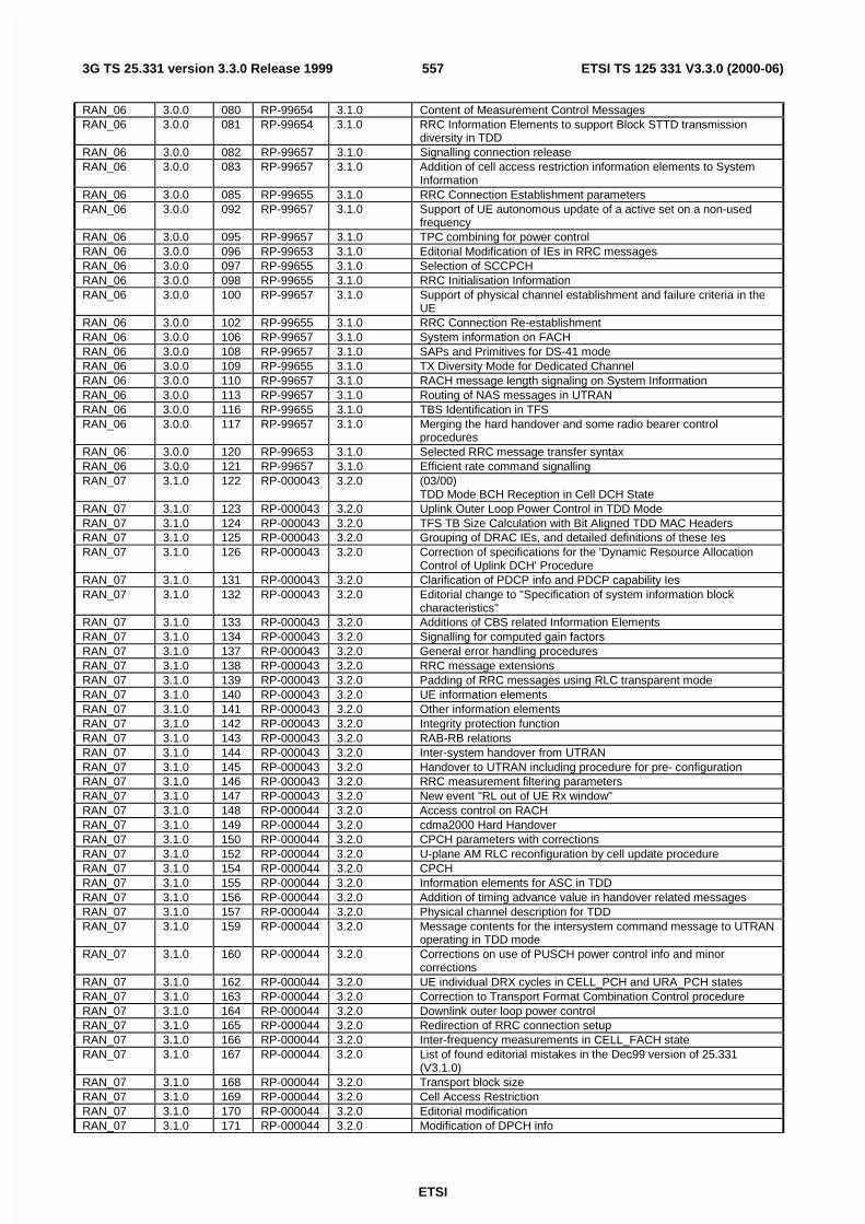
ETSI
ETSI TS 125 331 V3.3.0 (2000-06)5573G TS 25.331 version 3.3.0 Release 1999
RAN_06 3.0.0 080 RP-99654 3.1.0 Content of Measurement Control MessagesRAN_06 3.0.0 081 RP-99654 3.1.0 RRC Information Elements to support Block STTD transmission
diversity in TDDRAN_06 3.0.0 082 RP-99657 3.1.0 Signalling connection releaseRAN_06 3.0.0 083 RP-99657 3.1.0 Addition of cell access restriction information elements to System
InformationRAN_06 3.0.0 085 RP-99655 3.1.0 RRC Connection Establishment parametersRAN_06 3.0.0 092 RP-99657 3.1.0 Support of UE autonomous update of a active set on a non-used
frequencyRAN_06 3.0.0 095 RP-99657 3.1.0 TPC combining for power controlRAN_06 3.0.0 096 RP-99653 3.1.0 Editorial Modification of IEs in RRC messagesRAN_06 3.0.0 097 RP-99655 3.1.0 Selection of SCCPCHRAN_06 3.0.0 098 RP-99655 3.1.0 RRC Initialisation InformationRAN_06 3.0.0 100 RP-99657 3.1.0 Support of physical channel establishment and failure criteria in the
UERAN_06 3.0.0 102 RP-99655 3.1.0 RRC Connection Re-establishmentRAN_06 3.0.0 106 RP-99657 3.1.0 System information on FACHRAN_06 3.0.0 108 RP-99657 3.1.0 SAPs and Primitives for DS-41 modeRAN_06 3.0.0 109 RP-99655 3.1.0 TX Diversity Mode for Dedicated ChannelRAN_06 3.0.0 110 RP-99657 3.1.0 RACH message length signaling on System InformationRAN_06 3.0.0 113 RP-99657 3.1.0 Routing of NAS messages in UTRANRAN_06 3.0.0 116 RP-99655 3.1.0 TBS Identification in TFSRAN_06 3.0.0 117 RP-99657 3.1.0 Merging the hard handover and some radio bearer control
proceduresRAN_06 3.0.0 120 RP-99653 3.1.0 Selected RRC message transfer syntaxRAN_06 3.0.0 121 RP-99657 3.1.0 Efficient rate command signallingRAN_07 3.1.0 122 RP-000043 3.2.0 (03/00)
TDD Mode BCH Reception in Cell DCH StateRAN_07 3.1.0 123 RP-000043 3.2.0 Uplink Outer Loop Power Control in TDD ModeRAN_07 3.1.0 124 RP-000043 3.2.0 TFS TB Size Calculation with Bit Aligned TDD MAC HeadersRAN_07 3.1.0 125 RP-000043 3.2.0 Grouping of DRAC IEs, and detailed definitions of these IesRAN_07 3.1.0 126 RP-000043 3.2.0 Correction of specifications for the 'Dynamic Resource Allocation
Control of Uplink DCH' ProcedureRAN_07 3.1.0 131 RP-000043 3.2.0 Clarification of PDCP info and PDCP capability IesRAN_07 3.1.0 132 RP-000043 3.2.0 Editorial change to "Specification of system information block
characteristics"RAN_07 3.1.0 133 RP-000043 3.2.0 Additions of CBS related Information ElementsRAN_07 3.1.0 134 RP-000043 3.2.0 Signalling for computed gain factorsRAN_07 3.1.0 137 RP-000043 3.2.0 General error handling proceduresRAN_07 3.1.0 138 RP-000043 3.2.0 RRC message extensionsRAN_07 3.1.0 139 RP-000043 3.2.0 Padding of RRC messages using RLC transparent modeRAN_07 3.1.0 140 RP-000043 3.2.0 UE information elementsRAN_07 3.1.0 141 RP-000043 3.2.0 Other information elementsRAN_07 3.1.0 142 RP-000043 3.2.0 Integrity protection functionRAN_07 3.1.0 143 RP-000043 3.2.0 RAB-RB relationsRAN_07 3.1.0 144 RP-000043 3.2.0 Inter-system handover from UTRANRAN_07 3.1.0 145 RP-000043 3.2.0 Handover to UTRAN including procedure for pre- configurationRAN_07 3.1.0 146 RP-000043 3.2.0 RRC measurement filtering parametersRAN_07 3.1.0 147 RP-000043 3.2.0 New event "RL out of UE Rx window"RAN_07 3.1.0 148 RP-000044 3.2.0 Access control on RACHRAN_07 3.1.0 149 RP-000044 3.2.0 cdma2000 Hard HandoverRAN_07 3.1.0 150 RP-000044 3.2.0 CPCH parameters with correctionsRAN_07 3.1.0 152 RP-000044 3.2.0 U-plane AM RLC reconfiguration by cell update procedureRAN_07 3.1.0 154 RP-000044 3.2.0 CPCHRAN_07 3.1.0 155 RP-000044 3.2.0 Information elements for ASC in TDDRAN_07 3.1.0 156 RP-000044 3.2.0 Addition of timing advance value in handover related messagesRAN_07 3.1.0 157 RP-000044 3.2.0 Physical channel description for TDDRAN_07 3.1.0 159 RP-000044 3.2.0 Message contents for the intersystem command message to UTRAN
operating in TDD modeRAN_07 3.1.0 160 RP-000044 3.2.0 Corrections on use of PUSCH power control info and minor
correctionsRAN_07 3.1.0 162 RP-000044 3.2.0 UE individual DRX cycles in CELL_PCH and URA_PCH statesRAN_07 3.1.0 163 RP-000044 3.2.0 Correction to Transport Format Combination Control procedureRAN_07 3.1.0 164 RP-000044 3.2.0 Downlink outer loop power controlRAN_07 3.1.0 165 RP-000044 3.2.0 Redirection of RRC connection setupRAN_07 3.1.0 166 RP-000044 3.2.0 Inter-frequency measurements in CELL_FACH stateRAN_07 3.1.0 167 RP-000044 3.2.0 List of found editorial mistakes in the Dec99 version of 25.331
(V3.1.0)RAN_07 3.1.0 168 RP-000044 3.2.0 Transport block sizeRAN_07 3.1.0 169 RP-000044 3.2.0 Cell Access RestrictionRAN_07 3.1.0 170 RP-000044 3.2.0 Editorial modificationRAN_07 3.1.0 171 RP-000044 3.2.0 Modification of DPCH info

ETSI
ETSI TS 125 331 V3.3.0 (2000-06)5583G TS 25.331 version 3.3.0 Release 1999
RAN_07 3.1.0 172 RP-000045 3.2.0 Measurement control messageRAN_07 3.1.0 173 RP-000045 3.2.0 Reporting cell statusRAN_07 3.1.0 174 RP-000045 3.2.0 Additional IE for RB releaseRAN_07 3.1.0 175 RP-000045 3.2.0 Available SF in PRACH infoRAN_07 3.1.0 176 RP-000045 3.2.0 Traffic volume measurement eventRAN_07 3.1.0 177 RP-000045 3.2.0 Report of multiple cells on an event resultRAN_07 3.1.0 178 RP-000045 3.2.0 Editorial modification on Direct TransferRAN_07 3.1.0 179 RP-000045 3.2.0 Correction of the Security Mode Control procedureRAN_07 3.1.0 180 RP-000045 3.2.0 Maximum calculated Transport Format CombinationRAN_07 3.1.0 183 RP-000045 3.2.0 Additional DPCH IEs to align 25.331 with 25.214RAN_07 3.1.0 184 RP-000045 3.2.0 RB – DCH mappingRAN_07 3.1.0 188 RP-000045 3.2.0 Modifications related to FDD mode DSCHRAN_07 3.1.0 189 RP-000045 3.2.0 Identification of Shared Channel Physical Configuration in TDD
ModeRAN_07 3.1.0 192 RP-000045 3.2.0 Uplink Outer Loop Power Control During Hard HandoverRAN_07 3.1.0 193 RP-000045 3.2.0 Support of Multiple CCTrCH's in TDD ModeRAN_07 3.1.0 194 RP-000045 3.2.0 Uplink Physical Channel Control in TDD ModeRAN_07 3.1.0 201 RP-000045 3.2.0 Transfer of initial information from UE to target RNC prior to
handover to UTRANRAN_07 3.1.0 202 RP-000045 3.2.0 CN information elementsRAN_07 3.1.0 203 RP-000045 3.2.0 UTRAN mobility information elementsRAN_07 3.1.0 204 RP-000045 3.2.0 RB information elementsRAN_07 3.1.0 205 RP-000046 3.2.0 Physical channel information elementsRAN_07 3.1.0 206 RP-000046 3.2.0 UE capability information elementsRAN_07 3.1.0 207 RP-000046 3.2.0 UE variablesRAN_07 3.1.0 208 RP-000046 3.2.0 Actions when entering idle modeRAN_07 3.1.0 209 RP-000046 3.2.0 Usage of pilot bitsRAN_07 3.1.0 210 RP-000046 3.2.0 System information procedure correctionsRAN_07 3.1.0 212 RP-000046 3.2.0 Reconfiguration of cipheringRAN_07 3.1.0 213 RP-000046 3.2.0 Enhancements to RRC connection re-establishment procedureRAN_07 3.1.0 215 RP-000046 3.2.0 Updates to RRC Initialization Information transparent container and
addition of reverse direction container descriptionRAN_07 3.1.0 220 RP-000046 3.2.0 Changes in RRC messages to support lossless SRNC relocationRAN_07 3.1.0 229 RP-000046 3.2.0 Measurements of unlisted neighbouring cellsRAN_07 3.1.0 234 RP-000046 3.2.0 Inclusion of Location ServicesRAN_07 3.1.0 236 RP-000046 3.2.0 Application of Access Service Classes and relation to Access
ClassesRAN_07 3.1.0 252 RP-000046 3.2.0 DRX indicator presence and state entering mechanism at the end of
a procedureRAN_07 3.1.0 254 RP-000046 3.2.0 Physical shared channel allocation procedureRAN_07 3.1.0 255 RP-000046 3.2.0 Corrections to TDD specific parameters in PICH infoRAN_07 3.1.0 256 RP-000046 3.2.0 Editorial modificationsRAN_07 3.1.0 259 RP-000046 3.2.0 Introduction of mapping function information in Cell selection andRAN_07 3.1.0 263 RP-000046 3.2.0 Ciphering and integrity HFNRAN_07 3.1.0 267 RP-000046 3.2.0 New SIB for LCSRAN_07 3.1.0 268 RP-000047 3.2.0 Removal of synchronisation Case 3RAN_07 3.1.0 271 RP-000047 3.2.0 TX DiversityRAN_07 3.1.0 272 RP-000047 3.2.0 Update of tabular format clause 10RAN_07 3.1.0 273 RP-000047 3.2.0 ASN.1 descriptionRAN_08 3.2.0 228 RP-000222 3.3.0 (06/00)
Downlink power control in compressed modeRAN_08 3.2.0 260 RP-000222 3.3.0 Clarification on physical channel allocations in TDDRAN_08 3.2.0 261 RP-000222 3.3.0 TDD Measurements and ReportingRAN_08 3.2.0 262 RP-000222 3.3.0 Signalling of IEs related to System Information on FACHRAN_08 3.2.0 265 RP-000222 3.3.0 Transport Format Combination ControlRAN_08 3.2.0 269 RP-000222 3.3.0 Signalling of partial failure in radio bearer related proceduresRAN_08 3.2.0 275 RP-000222 3.3.0 Clarification on PDCP infoRAN_08 3.2.0 279 RP-000222 3.3.0 Editorial modification on Transport Ch capabilityRAN_08 3.2.0 280 RP-000222 3.3.0 Editorial modification on CN IERAN_08 3.2.0 281 RP-000222 3.3.0 Editorial modification on Physical CH IERAN_08 3.2.0 282 RP-000222 3.3.0 Editorial modification on ASN.1 descriptionRAN_08 3.2.0 283 RP-000222 3.3.0 IEs on SIB5/6RAN_08 3.2.0 285 RP-000222 3.3.0 Re-establishment timerRAN_08 3.2.0 286 RP-000222 3.3.0 CN DRX cycle coefficientRAN_08 3.2.0 287 RP-000222 3.3.0 Cell Access RestrictionRAN_08 3.2.0 288 RP-000222 3.3.0 Cell selection and re-selection parametersRAN_08 3.2.0 289 RP-000222 3.3.0 Modification on Measurement IERAN_08 3.2.0 291 RP-000222 3.3.0 RACH Transmission parametersRAN_08 3.2.0 292 RP-000222 3.3.0 SCCPCH System InfoRAN_08 3.2.0 293 RP-000222 3.3.0 Addition of HFN for RRC CONNECTION RE-ESTABLISHMENT
COMPLETERAN_08 3.2.0 294 RP-000223 3.3.0 RLC reconfiguration indicator

ETSI
ETSI TS 125 331 V3.3.0 (2000-06)5593G TS 25.331 version 3.3.0 Release 1999
RAN_08 3.2.0 296 RP-000223 3.3.0 RLC InfoRAN_08 3.2.0 297 RP-000223 3.3.0 Usage of Transport CH IDRAN_08 3.2.0 298 RP-000223 3.3.0 Transport format combination setRAN_08 3.2.0 300 RP-000223 3.3.0 Usage of U-RNTI and C-RNTI in DL DCCH messageRAN_08 3.2.0 301 RP-000223 3.3.0 Description of Cell Update ProcedureRAN_08 3.2.0 304 RP-000223 3.3.0 System information modification procedureRAN_08 3.2.0 305 RP-000223 3.3.0 Functional descriptions of the RRC messagesRAN_08 3.2.0 306 RP-000223 3.3.0 Clarification of CTFC calculationRAN_08 3.2.0 307 RP-000223 3.3.0 Compressed mode parametersRAN_08 3.2.0 309 RP-000223 3.3.0 Signalling procedure for periodic local authenticationRAN_08 3.2.0 310 RP-000223 3.3.0 Editorial corrections on securityRAN_08 3.2.0 311 RP-000223 3.3.0 Security capabilityRAN_08 3.2.0 312 RP-000223 3.3.0 Corrections on ASN.1 definitionsRAN_08 3.2.0 313 RP-000223 3.3.0 DRX cycle lower limitRAN_08 3.2.0 314 RP-000223 3.3.0 Removal of CPICH SIR measurement quantityRAN_08 3.2.0 315 RP-000223 3.3.0 Signalling connection release requestRAN_08 3.2.0 318 RP-000223 3.3.0 Change to IMEI coding from BCD to hexadecimalRAN_08 3.2.0 319 RP-000223 3.3.0 Removal of RLC sequence numbers from RRC initialisation
informationRAN_08 3.2.0 320 RP-000223 3.3.0 Addition of the length of PDCP sequence numbers into PDCP infoRAN_08 3.2.0 323 RP-000224 3.3.0 BSIC verification of GSM cellsRAN_08 3.2.0 324 RP-000224 3.3.0 Reporting cell statusRAN_08 3.2.0 325 RP-000224 3.3.0 RRC measurement filtering parametersRAN_08 3.2.0 326 RP-000224 3.3.0 Cell-reselection parameter signallingRAN_08 3.2.0 328 RP-000224 3.3.0 Multiplicity valuesRAN_08 3.2.0 329 RP-000224 3.3.0 Quality measurementsRAN_08 3.2.0 330 RP-000224 3.3.0 CPCH Status Indication mode correctionRAN_08 3.2.0 331 RP-000224 3.3.0 End of CPCH transmissionRAN_08 3.2.0 332 RP-000224 3.3.0 Handover to UTRAN procedureRAN_08 3.2.0 333 RP-000224 3.3.0 Harmonisation of access service classes in FDD and TDDRAN_08 3.2.0 334 RP-000224 3.3.0 Correction to usage of primary CCPCH info and primary CPICH infoRAN_08 3.2.0 335 RP-000224 3.3.0 Corrections and clarifications on system information handlingRAN_08 3.2.0 336 RP-000224 3.3.0 Editorial correctionsRAN_08 3.2.0 337 RP-000224 3.3.0 Editorial corrections on uplink timing advanceRAN_08 3.2.0 339 RP-000224 3.3.0 Correction of Transport Format Combination tabular format and
ASN.1RAN_08 3.2.0 340 RP-000224 3.3.0 UE variablesRAN_08 3.2.0 342 RP-000224 3.3.0 General error handlingRAN_08 3.2.0 344 RP-000224 3.3.0 System Information extensibility in ASN.1 definitionsRAN_08 3.2.0 345 RP-000224 3.3.0 Usage of pilot bitsRAN_08 3.2.0 346 RP-000224 3.3.0 RRC connection release procedureRAN_08 3.2.0 347 RP-000225 3.3.0 Alignment of Section 10.3 on methodology defined in 25.921RAN_08 3.2.0 348 RP-000225 3.3.0 Modifications of cell (re)selection parametersRAN_08 3.2.0 350 RP-000225 3.3.0 GPS time-of-week represented as seconds and fractions of secondsRAN_08 3.2.0 351 RP-000225 3.3.0 CPCH correctionsRAN_08 3.2.0 352 RP-000225 3.3.0 PLMN type selectionRAN_08 3.2.0 353 RP-000225 3.3.0 Paging and establishment cause valuesRAN_08 3.2.0 354 RP-000225 3.3.0 Common channel configurationsRAN_08 3.2.0 355 RP-000225 3.3.0 Clarification of prioritisation of logical channels in UERAN_08 3.2.0 357 RP-000225 3.3.0 UE capability correctionsRAN_08 3.2.0 358 RP-000225 3.3.0 Clarification of HFNRAN_08 3.2.0 359 RP-000225 3.3.0 Clarification of Integrity ProtectionRAN_08 3.2.0 360 RP-000225 3.3.0 RRC message size optimisation regarding TrCH parametersRAN_08 3.2.0 361 RP-000225 3.3.0 Protocol extensions in ASNRAN_08 3.2.0 362 RP-000225 3.3.0 Downloading of pre- defined configurations via SIB 16RAN_08 3.2.0 363 RP-000225 3.3.0 Optimisation of System InformationRAN_08 3.2.0 364 RP-000225 3.3.0 CPCH gain factorRAN_08 3.2.0 368 RP-000225 3.3.0 SFN Transmission Rate in TDD ModeRAN_08 3.2.0 371 RP-000225 3.3.0 Integrity ControlRAN_08 3.2.0 372 RP-000225 3.3.0 Modification to measurement event evaluationRAN_08 3.2.0 373 RP-000225 3.3.0 System Information related parametersRAN_08 3.2.0 375 RP-000226 3.3.0 Changes in RB mapping infoRAN_08 3.2.0 377 RP-000226 3.3.0 Editorial corrections to PRACH system information and Cell infoRAN_08 3.2.0 378 RP-000226 3.3.0 Editorial Corrections to 25.331 Procedures and Tabular FormatRAN_08 3.2.0 379 RP-000226 3.3.0 Corrections to figures and procedures for the failure casesRAN_08 3.2.0 380 RP-000226 3.3.0 Corrections on use of ORDERED_CONFIGRAN_08 3.2.0 382 RP-000226 3.3.0 Corrections to Transport Channel and RB Reconfiguration
proceduresRAN_08 3.2.0 383 RP-000226 3.3.0 Corrections to INITIAL DIRECT TRANSFER and UE CAPABILITY
INFORMATION CONFIRM proceduresRAN_08 3.2.0 384 RP-000226 3.3.0 Corrections to Transparent mode signalling info Tabular format and
ASN.1

ETSI
ETSI TS 125 331 V3.3.0 (2000-06)5603G TS 25.331 version 3.3.0 Release 1999
RAN_08 3.2.0 385 RP-000226 3.3.0 Corrections to Soft Handover messages and proceduresRAN_08 3.2.0 387 RP-000226 3.3.0 Corrections to RRC CONNECTION REJECT proceduresRAN_08 3.2.0 388 RP-000226 3.3.0 Transport format combination in TDD and Transport channel IDRAN_08 3.2.0 389 RP-000226 3.3.0 Signalling for dynamic TTI in TDDRAN_08 3.2.0 390 RP-000226 3.3.0 Usage of DCCH for Shared Channel Allocation messageRAN_08 3.2.0 391 RP-000226 3.3.0 Correction to physical channel IEs in TDDRAN_08 3.2.0 392 RP-000226 3.3.0 TDD preconfiguration for Handover to UTRANRAN_08 3.2.0 393 RP-000226 3.3.0 Corrections to measurement control descriptions and messagesRAN_08 3.2.0 394 RP-000226 3.3.0 Corrections on ASN.1 definitionsRAN_08 3.2.0 395 RP-000226 3.3.0 Addition of the Segmentation indication field for transparent mode
RLC in the RLC InfoRAN_08 3.2.0 396 RP-000226 3.3.0 Radio Bearer identity for CCCHRAN_08 3.2.0 397 RP-000226 3.3.0 ASN.1 definitions for RRC information between network nodesRAN_08 3.2.0 398 RP-000227 3.3.0 NAS RoutingRAN_08 3.2.0 399 RP-000227 3.3.0 DPCCH power control preambleRAN_08 3.2.0 400 RP-000227 3.3.0 Modifications of Assisted GPS MessagesRAN_08 3.2.0 401 RP-000227 3.3.0 Choice of Initial UE IdentityRAN_08 3.2.0 402 RP-000227 3.3.0 ANSI-41 information elementsRAN_08 3.2.0 404 RP-000227 3.3.0 RLC value rangesRAN_08 3.2.0 408 RP-000227 3.3.0 HFN ResetRAN_08 3.2.0 409 RP-000227 3.3.0 Clarification on ciphering parameters and integrity protection
procedure in case of SRNS relocationRAN_08 3.2.0 410 RP-000227 3.3.0 Clarification of compressed mode activation and configuration failureRAN_08 3.2.0 412 RP-000227 3.3.0 Modification of the RLC Size IERAN_08 3.2.0 414 RP-000227 3.3.0 CPCH DL Power controlRAN_08 3.2.0 415 RP-000227 3.3.0 SFN measurements in TDD

561
ETSI
ETSI TS 125 331 V3.3.0 (2000-06)3G TS 25.331 version 3.3.0 Release 1999
History
Document history
V3.1.0 January 2000 Publication
V3.2.0 March 2000 Publication
V3.3.0 June 2000 Publication