etso-c199 date: 21.2.2018 european aviation safety agencyrtca/do-181e, mops for air traffic control...
TRANSCRIPT
ED Decision 2018/002/R
Annex II
ETSO-C199
Date: 21.2.2018
Page 71 of 117
European Aviation Safety Agency
European Technical Standard Order
Subject: TRAFFIC AWARENESS BEACON SYSTEM (TABS)
1 - Applicability
This ETSO provides the requirements for the applicable equipment class defined by this ETSO which
traffic awareness beacon systems (TABSs) that are designed and manufactured on or after the date of
this ETSO must meet in order to be identified with the applicable ETSO marking.
TABS devices are distinctly different from other transponders. TABS devices are intended for voluntary
equipage on aircraft exempted from carrying a transponder or automatic dependent surveillance-
broadcast (ADS-B) equipment, such as gliders, balloons and aircraft without electrical systems. TABS
devices do not meet the transponder or ADS-B requirements defined in Commission Implementing
Regulation (EU) No 1207/2011 of 22 November 2011 laying down requirements for the performance
and the interoperability of surveillance for the single European sky. TABS equipment built to the
minimum requirements of this ETSO will enable an aircraft to be visible to other aircraft equipped
with:
— a Traffic Advisory System (TAS) as defined in ETSO-C147();
— a Traffic Alert and Collision Avoidance System I (TCAS I) as defined in ETSO-C118();
— a Traffic Alert and Collision Avoidance System II, (TCAS II), as defined in ETSO-C119d;
— ADS-B IN capability as defined in ETSO-C154c, ETSO-C166b (), and ETSO-C195b.
2 - Procedures
2.1 - General
Applicable procedures are detailed in CS-ETSO, Subpart A.
2.2 - Specific
None.
3 - Technical conditions
3.1 - Basic
3.1.1 - Minimum performance standard TABS requirements are derived from existing transponder and ADS-B requirements. Equipment
meeting only the minimum TABS requirements will provide the capability to be seen by other aircraft
equipped with traffic advisory systems but may not support detection by ground surveillance systems
relying on full transponder functionality. A designer building equipment to meet this ETSO may decide

ED Decision 2018/002/R
Annex II
ETSO-C199
Date: 21.2.2018
Page 72 of 117
to incorporate more capability than what is outlined in this ETSO as long as it meets the applicable
requirements in the referenced standards (e.g., EUROCAE ED-73E, MOPS for Secondary Surveillance
Radar Mode S Transponders, as amended by Appendix 1 to ETSO-C112e).
TABS functionality is divided into four categories: the transponder function, the altitude source function, the ADS-B OUT function, and the position source function.
A Class A TABS:
— includes the transponder, altitude source, and ADS-B OUT functionality; refer to
Subparagraphs (1), (2), and (3) below;
— consists of a Class A device, or a TSO-C112e and TSO-C166b compliant device.
A Class B TABS:
— includes the Global Navigation Satellite System (GNSS) position source functionality; refer
to Subparagraph (4) below;
— consists of a Class B device, or a ETSO-C129a (cancelled), ETSO-C145c or later revision,
ETSO-C146c or later revision or ETSO-C196b-compliant GPS.
A TABS may include an ADS-B IN function but it is not required. If implemented, the ADS-B IN function shall meet the performance specified in ETSO-C195b as well as ETSO-C154c, or ETSO-C166b, or all three. A TABS is intended to make the aircraft a valid TIS-B and ADS-R client.
(a) The transponder functionality must meet a subset of the requirements in document RTCA/DO-181E, MOPS for Air Traffic Control Radar Beacon System/Mode Select (ATCRBS/Mode S) Airborne Equipment, dated March 17, 2011, section 2, for a Level 2, Class 2 transponder as modified by Appendix 1.
(b) The altitude source functionality must meet the requirements of ETSO-C88a or later revision, Automatic Pressure Altitude Reporting Code Generating Equipment, dated August 5, 2016.
(c) The ADS-B OUT function must meet a subset of the requirements found in document EUROCAE ED-102A, Minimum Operational Performance Standards for 1090 MHz Automatic Dependent Surveillance – Broadcast (ADS-B) and Traffic Information Services-Broadcast (TIS-B), dated December, 2009, including Corrigendum-1, section 2, dated January, 2012, Class B0 as modified by Appendix 1. The system must be built such that it transmits Navigation Integrity Code (NIC), Navigation Accuracy Category for Position (NACp), Navigation Accuracy Category for Velocity (NACv), Geometric Vertical Accuracy (GVA), and Safety Integrity Level (SIL) values appropriate for the GNSS receiver used.
(d) The position source function must use a GNSS receiver that meets the requirements defined in Appendix 1. The intent of this ETSO is to allow the use of commercially available GNSS position sources. The receiver must be capable of using SBAS provided corrections and health messages, as defined in Appendix 1, in order to provide a means to prevent the TABS from transmitting false or misleading information. The receiver may continue to provide position when outside of SBAS coverage or when using unmonitored satellites. TABS Class B position sources may not be used for certified navigation equipment.
3.1.2 - Environmental Standard
See CS-ETSO, Subpart A, paragraph 2.1.
For Class A equipment, demonstrate the required performance under the test conditions specified in RTCA/DO-181E Section 2.3 and EUROCAE ED-102A, including Corrigendum-1, Section 2.3, dated January, 2012,

ED Decision 2018/002/R
Annex II
ETSO-C199
Date: 21.2.2018
Page 73 of 117
For Class B equipment, demonstrate the required performance under the test conditions specified in Appendix 3.
3.1.3 - Software
See CS-ETSO, Subpart A, paragraph 2.2.
This requirement applies to Class A equipment only. Class B equipment is exempt from software qualification defined in this paragraph.
3.1.4 - Airborne Electronic Hardware
See CS-ETSO, Subpart A, paragraph 2.3.
This requirement applies to Class A equipment only. Class B equipment is exempt from electronic hardware qualification defined in this paragraph.
3.2 - Specific
3.2.1 - Failure Condition Classification
See CS-ETSO, Subpart A, paragraph 2.4.
Failure of the function defined in paragraph 3.1.1 of this ETSO resulting in misleading information is a minor failure condition.
Failure of the function defined in paragraph 3.1.1 of this ETSO resulting in loss of function is a minor failure condition.
Class B equipment is intended to be met by commercially available GNSSs and is unlikely to be designed specifically to support a minor hazard classification. Class B equipment suitabili ty for supporting the function in paragraph 3.1.1 of this ETSO is established by performing the functional and environmental testing in Appendix 2 and Appendix 3 of this ETSO with no further analysis required.
4 - Marking
4.1 - General
Marking as detailed in CS-ETSO, Subpart A, paragraph 1.2.
4.2 - Specific
None.
5 - Availability of Referenced Documents
See CS-ETSO, Subpart A, paragraph 3.
EUROCONTROL Documents: EUROCONTROL, STA/R/460/0001/1, Study to Address the Detection and Recognition of Light Aircraft in the Current and Future ATM Environment, Issue 1.0, Final Report, dated 31 March 2005.
EUROCONTROL Surveillance Document Library:
https://www.eurocontrol.int/articles/surveillance-library
FCC Documents: Federal Communication Commission document OET Bulletin 65 Ed 97-01, Evaluating Compliance with FCC Guidelines for Human Exposure to Radiofrequency Electromagnetic Fields is available on the internet at: http://transition.fcc.gov/Bureaus/Engineering_Technology/Documents/bulletins/oet65/oet65.pdf US Code of Federal Regulations (CFR) Documents: order copies of 14 CFR parts 21, 45 and 91 from the Superintendent of Documents, Government Printing Office, P.O. Box 979050, St. Louis, MO 63197. Telephone (202) 512-1800, fax (202) 512-2250. You can also download copies online at: http://www.ecfr.gov/cgi-bin/text-idx?tpl=/ecfrbrowse/

ED Decision 2018/002/R
Annex II
ETSO-C199
Date: 21.2.2018
Page 74 of 117
UK Public Health Documents Public Health England document HPA-RPD-031, Exposure to EMFs from Lightweight Aviation Transponders, dated September 2007, ISBN 978¬0-85951-605-1, can be obtained on line by going to:
http://www.hpa.org.uk/Publications/Radiation/HPARPDSeriesReports/HpaRpd031/
Global Positioning System Signals, Measurements, and Performance, Ganga-Jamuna Press, by Pratap Misra and Per Enge. ISBN: 0-9709544-0-9

ED Decision 2018/002/R
Annex II
ETSO-C199
Date: 21.2.2018
Page 75 of 117
APPENDIX 1
Traffic Awareness Beacon System Requirements
A1 Introduction A1.1 TABS Intent A1.1.1 The intent of a TABS is to increase safety by encouraging the voluntary equipage of a low cost, compact, easy to install device that will allow other aircraft equipped with collision avoidance systems and traffic advisory systems to track and display the TABS aircraft. TABS are intended to be used on aircraft that are exempted from carrying a transponder or Automatic Dependent Surveillance - Broadcast (ADS-B) equipment, such as gliders, balloons and aircraft without electrical systems. TABS devices do not meet the transponder requirements defined in Commission Implementing Regulation (EU) No 1207/2011 of 22 November 2011 laying down requirements for the performance and the interoperability of surveillance for the single European sky. A TABS will allow these exempted aircraft to be visible to other aircraft equipped with:
— a Traffic Advisory System (TAS) as defined in ETSO-C147();
— a Traffic Alert and Collision Avoidance System I (TCAS I) as defined in ETSO-C118();
— a Traffic Alert and Collision Avoidance System II, (TCAS II), as defined in ETSO-C119d;
— ADS-B IN capability as defined in ETSO-C166b, and ETSO-C195b;
— ADS-B IN capability as defined in ETSO-C154c in airspace where UAT is used.
A1.1.2 A TABS is designed to: — reply to ATCRBS Mode C, and Mode S UF=0, 4, 5, 20 and 21 interrogations;
— not reply to ATCRBS Mode A interrogations;
— not reply to Mode S UF=11, and 16 interrogations;
— incorporate ETSO-C88b, Automatic Pressure Altitude Reporting Code-Generating Equipment;
— transmit ADS-B Messages: Aircraft Identification and Category, Airborne Position, Airborne Velocity, Emergency Priority Status Message, and Aircraft Operational Status;
— optionally provide Surface Position Messages;
— optionally use a commercial GNSS source meeting the requirements of this ETSO.
A1.1.3 A TABS can potentially act as a low-cost platform for other aviation applications. Although additional capabilities are beyond the scope of this ETSO, TABS may include additional functions such as data loggers, search and rescue transmitter, or provide flight information services. A1.2 Requirements A1.2.1 TABS requirements are derived from existing Mode S transponder and 1090 MHz Extended Squitter ADS-B requirements. A designer building equipment to meet this ETSO may decide to incorporate the full transponder and ADS-B capability by using a device that meets ETSO-C112e and ETSO-C166b. If electing to implement full functionality, they must demonstrate that functionality against the unmodified test procedures EUROCAE ED-102A, including Corrigendum-1, dated January, 2012, required by ETSO-C112e and ETSO-C166b respectively. Designers that wish to take advantage of the reduced transponder requirements afforded to

ED Decision 2018/002/R
Annex II
ETSO-C199
Date: 21.2.2018
Page 76 of 117
ETSO-C199 Class A devices must meet the modified requirements outlined in paragraphs A1.2.3 Transponder Function Requirements, A1.2.4 Altitude Source Function Requirements, and A1.2.5 ADS-B OUT Function Requirements in this Appendix in their entirety. Designers wishing to take advantage of the Class B reduced GNSS requirements will need to meet the requirements outlined in paragraphs A1.2.6 GNSS Position Source Function Requirements. A1.2.2 MOPS text is used here with the permission of the RTCA. Table 1 provides notes in italics and parenthesis explaining how to read the tables that modify the text in the source documents.
(Source document reference) Modified text for this ETSO
(This is a copy of the original text from the source document. Material to be deleted from this original text is marked with strikethrough formatting.)
(This is the requirement for this ETSO. Modifications to the source text are marked in bold and underlined to assist in identifying changes).
Table 1 (Source document reference) (type of change) A1.2.3 Transponder Function Requirements Derived From DO-181E (For Class A Devices) A1.2.3.1 The transponder function must meet the Minimum Performance Standards (MPS) qualification and documentation requirements in RTCA, Inc. document RTCA/DO-181E, Section 2, for a Level 2, Class 2, transponder as modified below. A1.2.3.1.1 Flight Crew Control Function Changes A1.2.3.1.2 A cost factor in any device is the control and display functions to interface with the human operator. TABS display and control requirements are a subset of those required for transponders. Some user controls are allowed via an external device prior to flight (e.g., a personal electronic device (PED)). If the system is powered by batteries, display of available battery life is recommended. Table 2 provides an overview of flight crew control functions.
Operation mode Required Controls Required Indicators
In flight (i.e., control head)
- Power, - Emergency (3/A code 7700) - IDENT (optional)
Power on, Transponder Fail ADS-B Fail Battery indicator (optional)
Non flight (optional in flight) (i.e., Personal Electronic Device PED)
- Set 4096 code, - Set Flight ID
Display of 4096 code, Display of Flight ID
Maintenance actions (allowed in non-flight conditions only)
- Set ICAO 24 bit aircraft address, - Set implementation specific configuration
Display of ICAO 24 bit aircraft address, Display of implementation specific configuration. Display software version (optional)
Table 2 Summary of Control and Indication Requirements by Operation Mode A1.2.3.1.3 RTCA/DO-181E, Section 2.1.7 a, Flight Crew Control Functions, is amended as shown in Table 3.
DO-181E text Modified text for this ETSO

ED Decision 2018/002/R
Annex II
ETSO-C199
Date: 21.2.2018
Page 77 of 117
The following functions Shall be provided a. A means of selecting each of the ATCRBS 4096 reply codes, and of indicating the code selected.
The following functions SHALL be provided as indicated in items a-f. a. A means of selecting and displaying the ATCRBS 4096 code on the ground SHALL be provided. A means of selecting and displaying the ATCRBS 4096 code in flight is optional. A means of setting the Mode 3/A code to 7700 (emergency), either by entering in the value or an automated means such as a switch, SHALL be provided. A means of setting an alternate 4096 code other than the primary 4096 code, either by entering in the value or an automated means such as a switch, SHALL be provided.
Table 3 DO-181E Section 2.1.7 a amendment A1.2.3.1.4 RTCA/DO-181E, Section 2.1.7 b, Flight Crew Control Functions, is amended as shown in Table 4.
DO-181E text Modified text for this ETSO
The following functions Shall be provided b. A means of selecting the air/ground state: 1) An automatic means Shall be the only acceptable means to determine the air/ground state. 2) If an automatic means is not available, the transponder Shall ensure that the air/ground state is Airborne
The following functions SHALL be provided as indicated in items a-f. b. A means of selecting the air/ground state: 1) An automatic means to determine the air/ground state is recommended. 2) If an automatic means is not implemented, the transponder SHALL ensure that the air/ground state is Airborne.
Table 4 DO-181E Section 2.1.7 b amendment A1.2.3.1.5 RTCA/DO-181E, Section 2.1.7 c, Flight Crew Control Functions, is amended as shown in Table 5.
DO-181E text Modified text for this ETSO
The following functions Shall be provided c. A means of selecting the condition in which all transponder functions, other than transmission on the reply frequency and associated self-testing, are operational (i.e., the Standby condition). Return to normal operation from this condition Shall be possible within five seconds.
The following functions SHALL be provided as indicated in items a-f. c. A means of selecting the condition in which all transponder functions, other than transmission on the reply frequency and associated self-testing, are operational (i.e., the Standby condition) is not required. However, if provided, return to normal operation from Standby condition SHALL be possible within five seconds.
Table 5 DO-181E Section 2.1.7 c amendment A1.2.3.1.6 RTCA/DO-181E, Section 2.1.7 d, Flight Crew Control Functions, is amended as shown in Table 6.
DO-181E text Modified text for this ETSO
The following functions Shall be provided d. A means of initiating the IDENT (SPI) feature.
The following functions SHALL be provided as indicated in items a-f. d. A means of initiating the IDENT (SPI) feature

ED Decision 2018/002/R
Annex II
ETSO-C199
Date: 21.2.2018
Page 78 of 117
is optional.
Table 6 DO-181E Section 2.1.7 d amendment A1.2.3.2 Reply Rate Capability Changes A1.2.3.2.1 This section reduces the minimum reply rate capability of the TABS consistent with the interrogation acceptance based on two assumptions. The following rationale describes how the modified reply rates were chosen. A1.2.3.2.1.1 Assumption 1. The worst case Mode C interrogation count in a 100-millisecond interval from one ATCRBS radar is approximately 14 interrogations. Four ATCRBS radar overlapping beam dwells in a second is approximately 53 Mode C interrogations. The Mode C interrogation acceptance rate from 10 TCAS I units is approximately 15 interrogations per second. This represents a total demand on the TABS of 68 Mode C replies per second for this example. A1.2.3.2.1.2 Assumption 2. The worst case Mode S reply rate is primarily derived from the expected interrogation pattern of a set of 50 nearby TCAS II units all equipped with hybrid surveillance. The radar load from only roll-call interrogations would be small and would require networked sensors, otherwise the Mode S ground interrogation acceptance rate from radar systems would be zero. A1.2.3.2.2 Based on assumptions 1 and 2, RTCA/DO-181E Section 2.2.3.4 Reply Rate Capability is changed as follows: A1.2.3.2.2.1 RTCA/DO-181E, Section 2.2.3.4.1 a, ATCRBS Reply Rate Capability is amended as shown in Table 7.
DO-181E text Modified text for this ETSO
The transponder Shall be able to continuously generate at least 500 ATCRBS 15-pulse replies per second.
The transponder Shall be able to continuously generate at least 100 ATCRBS 15-pulse replies per second.
Table 7 DO-181E Section 2.2.3.4.1 a amendment A1.2.3.2.2.2 RTCA/DO-181E, Section 2.2.3.4.1 c, ATCRBS Reply Rate Capability is amended as shown in Table 8.
DO-181E text Modified text for this ETSO
For Class 2 equipment, the transponder Shall be capable of a peak reply rate of 1000 ATCRBS 15-pulse replies per second for a duration of 100 milliseconds.
For Class 2 equipment, the transponder SHALL be capable of a peak reply rate of 150 ATCRBS 15-pulse replies per second for a duration of 100 milliseconds.
Table 8 DO-181E Section 2.2.3.4.1 c added A1.2.3.2.2.3 RTCA/DO-181E, Section 2.2.3.4.2 a, Mode S Reply Rate Capability, is amended as shown in Table 9.
DO-181E text Modified text for this ETSO
A transponder equipped for only short Mode S downlink formats (DF), Shall have the following minimum reply rate capabilities: 50 Mode S replies in any 1-second interval.
A transponder equipped for only short Mode S downlink formats (DF), SHALL have the following minimum reply rate capabilities: 29 Mode S replies in any 1-second interval.

ED Decision 2018/002/R
Annex II
ETSO-C199
Date: 21.2.2018
Page 79 of 117
18 Mode S replies in a 100-millisecond interval. 8 Mode S replies in a 25-millisecond interval. 4 Mode S replies in a l.6-millisecond interval.
10 Mode S replies in a 100-millisecond interval. 5 Mode S replies in a 25-millisecond interval. 3 Mode S replies in a l.6-millisecond interval.
Table 9 DO-181E Section 2.2.3.4.2 a amendment A1.2.3.2.2.4 RTCA/DO-181E, Section 2.2.3.4.2 b, Mode S Reply Rate Capability, is amended as shown in Table 10.
DO-181E text Modified text for this ETSO
A transponder equipped for long Mode S reply formats Shall be able to transmit as long replies: At least 16 of the 50 Mode S replies in any 1-second interval. At least 6 of the 18 Mode S replies in a 100 millisecond interval. At least 4 of the 8 Mode S replies in a 25 millisecond interval. At least 2 of the 4 Mode S replies in a l.6 millisecond interval.
A transponder equipped for long Mode S reply formats SHALL be able to transmit as long replies: At least 10 of the 29 Mode S replies in any 1-second interval. At least 4 of the 10 Mode S replies in a 100-millisecond interval. At least 3 of the 5 Mode S replies in a 25-millisecond interval. At least 2 of the 4 Mode S replies in a l.6-millisecond interval.
Table 10 DO-181E Section 2.2.3.4.2 b amendment A1.2.3.3 Reply Rate Limiting Changes A1.2.3.3.1 The modifications in this section address reply rate limiting for ATCRBS and Mode S reply rates consistent with the previous section. A1.2.3.3.2 RTCA/DO-181E, Section 2.2.7.3.1, ATCRBS Reply Rate Limiting is amended as shown in Table 11.
DO-181E text Modified text for this ETSO
A sensitivity-reduction reply rate limit Shall be incorporated in the transponder for ATCRBS replies. The limit Shall be capable of being adjusted between 500 continuous ATCRBS Mode A and Mode C replies per second and the maximum continuous rate of which the transponder is capable, or 2000 replies per second, whichever is less, without regard to the number of pulses in each reply. Sensitivity reduction Shall apply only to the receipt of ATCRBS, ATCRBS/Mode S All-Call, and ATCRBS-Only All-Call interrogations.
A sensitivity-reduction reply rate limit SHALL be incorporated in the transponder for ATCRBS replies. The limit SHALL be capable of being adjusted between 100 continuous ATCRBS Mode C replies per second and the maximum continuous rate of which the transponder is capable, or 200 replies per second, whichever is less, without regard to the number of pulses in each reply. Sensitivity reduction SHALL apply only to the receipt of ATCRBS interrogations.
Table 11 DO-181E Section 2.2.7.3.1 amendment

ED Decision 2018/002/R
Annex II
ETSO-C199
Date: 21.2.2018
Page 80 of 117
A1.2.3.4 RTCA/DO-181E, Section 2.2.13.1.2 c, Variable Direct Data is amended as shown in Table 12.
DO-181E text Modified text for this ETSO
c. On-the-Ground Condition The transponder Shall report the automatically determined on-the-ground state as determined by the aircraft in the Flight Status (FS), Vertical Status (VS), and Capability (CA) fields (see §2.2.14.4.15, §2.2.14.4.42, and §2.2.14.4.6), except when reporting airborne status when on-the-ground is reported to the transponder under the conditions specified in §2.2.18.2.7.
c. On-the-Ground Condition The transponder may report the automatically determined on-the-ground state as determined by the aircraft in the Flight Status (FS), Vertical Status (VS), and Capability (CA) fields (see paragraphs 2.2.14.4.15, 2.2.14.4.42, and 2.2.14.4.6), except when reporting airborne status when on-the-ground is reported to the transponder under the conditions specified in paragraph 2.2.18.2.7.
Table 12 DO-181E Section 2.2.13.1.2 c amendment A1.2.3.5 RTCA/DO-181E, Section 2.2.13.1.2 d, Variable Direct Data, is amended as shown in Table 13.
DO-181E text Modified text for this ETSO
d. Special Position Identification (SPI) In the ATCRBS mode, an SPI pulse Shall be transmitted upon request, following a Mode A reply. In the FS field of Mode S replies, an equivalent of the ATCRBS SPI pulse Shall be transmitted upon the same request. The code is transmitted for 18 ±1.0 seconds after initiation and can be reinitiated at any time.
d. Special Position Identification (SPI) In the FS field of Mode S replies, an equivalent of the ATCRBS SPI pulse shall be transmitted upon request if the optional IDENT flight crew control is implemented per A1.2.3.1.6 of this ETSO. The code is transmitted for 18 ± 1.0 seconds after initiation and can be reinitiated at any time.
Table 13 DO-181E Section 2.2.13.1.2 c amendment A1.2.3.6 RTCA/DO-181E, Section 2.2.13.1.2 e, Variable Direct Data, is amended as shown in Table 14.
DO-181E text Modified text for this ETSO
e. Aircraft Identification Data If the aircraft uses a flight number for aircraft identification, a means Shall be provided for the variable aircraft identification to be inserted by the pilot while on the ground, or during flight. The means for modifying and displaying aircraft identification Shall be a simple crew action independent of the entry of other flight data.
e. Aircraft Identification Data If the aircraft uses a flight number for aircraft identification, a means SHALL be provided for the variable aircraft identification to be inserted by the pilot while on the ground. A means may be provided for modifying aircraft identification in flight.
Table 14 DO-181E Section 2.2.13.1.2 e amendment A1.2.3.7 Interrogation Acceptance Protocol Changes (All-Call reply capability) A1.2.3.7.1 The transponder All-Call interrogation reply acceptance requirements are reduced to reply only to ATCRBS Mode C (P1-P3) interrogations. The purpose is to reduce the reply rate of TABS while maintaining TCAS and TAS interoperability. The requirements of this ETSO are identical to RTCA/DO-181E except for the changes shown below. A1.2.3.7.2 RTCA/DO-181E, Section 2.2.18.2.2 b, Interrogation Acceptance Protocol (Figure 2-12), is amended as shown in Table 15.

ED Decision 2018/002/R
Annex II
ETSO-C199
Date: 21.2.2018
Page 81 of 117
DO-181E text Modified text for this ETSO
All-Call Address – If the address extracted from the received interrogation consists of 24 ONEs and UF=11, the transmission is a Mode S-Only All-Call and the received interrogation Shall be accepted according to “i” below unless the lockout protocol is in effect. Mode S-Only All-Call Shall not be accepted (no replies) when in the on-the-ground state (consistent with the CA, VS and FS fields)
All-Call Address – If the address extracted from the received interrogation consists of 24 ONEs and UF=11, the transmission is a Mode S-Only All-Call and the received interrogation SHALL not be accepted.
Table 15 DO-181E Section 2.2.18.2.2 b amendment
A1.2.3.7.3 RTCA/DO-181E, Section 2.2.18.2.2 c, Interrogation Acceptance Protocol (Figure 2-12), is amended as shown in Table 16.
DO-181E text Modified text for this ETSO
ATCRBS/Mode S All-Call – An ATCRBS/Mode S All-Call interrogation (1.6 microseconds P4) Shall be accepted unless the TD timer is running or side lobe suppression is in effect or when in the “on-the-ground” state (consistent with the CA, VS and FS fields).
ATCRBS/Mode S All-Call – An ATCRBS/Mode S All-Call interrogation (1.6 microseconds P4) SHALL not be accepted.
Table 16 DO-181E Section 2.2.18.2.2 c amendment A1.2.3.8 RTCA/DO-181E, Section 2.2.18.2.2 g, Interrogation Acceptance Protocol, paragraph g, All-Call Lockout Conditions, is amended as shown in Table 17.
DO-181E text Modified text for this ETSO
All-Call Lockout Conditions – On receipt of a Mode S-Only All-Call (UF=11) containing an Interrogator Code (IC and CL fields) corresponding to the designator of a running TL timer, the interrogation Shall not be accepted. unless the contained PR code is 8 through 12 and the “on-the-ground” report (CA, VS or FS field) does not include the ground condition. Upon receipt of a Mode S-Only All-Call (UF=11) containing II=0, the interrogation Shall be accepted if the TD timer is not running or if the received PR code is 8 through 12 and the “on-the-ground” report (CA, VS or FS field) does not include the ground condition.
All-Call Lockout Conditions – On receipt of a Mode S-Only All-Call (UF=11) the interrogation SHALL not be accepted.
Table 17 DO-181E Section 2.2.18.2.2 g amendment A1.2.3.9 RTCA/DO-181E, Section 2.2.18.2.2 i, Interrogation Acceptance Protocol Stochastic All-Calls, should not be implemented in Class A TABS. A1.2.3.10 Two new sections are added here to explicitly define interrogation acceptance criteria for TABS.
ED Decision 2018/002/R
Annex II
ETSO-C199
Date: 21.2.2018
Page 82 of 117
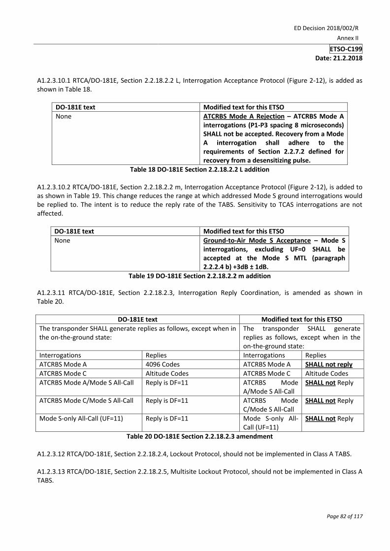
A1.2.3.10.1 RTCA/DO-181E, Section 2.2.18.2.2 L, Interrogation Acceptance Protocol (Figure 2-12), is added as shown in Table 18.
DO-181E text Modified text for this ETSO
None ATCRBS Mode A Rejection – ATCRBS Mode A interrogations (P1-P3 spacing 8 microseconds) SHALL not be accepted. Recovery from a Mode A interrogation shall adhere to the requirements of Section 2.2.7.2 defined for recovery from a desensitizing pulse.
Table 18 DO-181E Section 2.2.18.2.2 L addition A1.2.3.10.2 RTCA/DO-181E, Section 2.2.18.2.2 m, Interrogation Acceptance Protocol (Figure 2-12), is added to as shown in Table 19. This change reduces the range at which addressed Mode S ground interrogations would be replied to. The intent is to reduce the reply rate of the TABS. Sensitivity to TCAS interrogations are not affected.
DO-181E text Modified text for this ETSO
None Ground-to-Air Mode S Acceptance – Mode S interrogations, excluding UF=0 SHALL be accepted at the Mode S MTL (paragraph 2.2.2.4 b) +3dB ± 1dB.
Table 19 DO-181E Section 2.2.18.2.2 m addition
A1.2.3.11 RTCA/DO-181E, Section 2.2.18.2.3, Interrogation Reply Coordination, is amended as shown in Table 20.
DO-181E text Modified text for this ETSO
The transponder SHALL generate replies as follows, except when in the on-the-ground state:
The transponder SHALL generate replies as follows, except when in the on-the-ground state:
Interrogations Replies Interrogations Replies
ATCRBS Mode A 4096 Codes ATCRBS Mode A SHALL not reply
ATCRBS Mode C Altitude Codes ATCRBS Mode C Altitude Codes
ATCRBS Mode A/Mode S All-Call Reply is DF=11 ATCRBS Mode A/Mode S All-Call
SHALL not Reply
ATCRBS Mode C/Mode S All-Call Reply is DF=11 ATCRBS Mode C/Mode S All-Call
SHALL not Reply
Mode S-only All-Call (UF=11) Reply is DF=11 Mode S-only All-Call (UF=11)
SHALL not Reply
Table 20 DO-181E Section 2.2.18.2.3 amendment A1.2.3.12 RTCA/DO-181E, Section 2.2.18.2.4, Lockout Protocol, should not be implemented in Class A TABS. A1.2.3.13 RTCA/DO-181E, Section 2.2.18.2.5, Multisite Lockout Protocol, should not be implemented in Class A TABS.

ED Decision 2018/002/R
Annex II
ETSO-C199
Date: 21.2.2018
Page 83 of 117
A1.2.3.14 RTCA/DO-181E, Section 2.2.18.2.7, Flight Status and Vertical Status Protocols are amended as shown in Table 21.
DO-181E text Modified text for this ETSO
Mode S-equipped aircraft Shall report details of their flight status. The source of and the rules for such reports are as follows: a. Alert – The transponder Shall transmit the 4096 identification code in ATCRBS Mode A replies and in the ID field of downlink format DF=5. This code can be changed by the pilot, and when a change is made an alert condition Shall be established. If the identification code is changed to 7500, 7600 or 7700, the alert condition Shall be permanent. If the identification code is changed to any other value, the alert condition Shall be temporary and self-canceling after 18 ± 1 seconds (TC timer). The TC timer Shall be retriggered and continued for 18 ± 1 seconds after any change has been accepted by the transponder function. The alert condition Shall be reported in the FS field. The permanent alert condition Shall be terminated and replaced by a temporary alert condition when the identification code is set to a value other than 7500, 7600 or 7700.
Mode S-equipped aircraft SHALL report details of their flight status. The source of and the rules for such reports are as follows: a. Alert – The transponder SHALL transmit the 4096 identification code in the ID field of downlink format DF=5. When a change is made an alert condition SHALL be established. If the identification code is changed to 7500, 7600 or 7700, the alert condition SHALL be permanent. If the identification code is changed to any other value, the alert condition SHALL be temporary and self-cancelling after 18 ± 1 seconds (TC timer). The TC timer SHALL be retriggered and continued for 18 ± 1 seconds after any change has been accepted by the transponder function. The alert condition SHALL be reported in the FS field. The permanent alert condition SHALL be terminated and replaced by a temporary alert condition when the identification code is set to a value other than 7500, 7600 or 7700.
Table 21 DO-181E Section 2.2.18.2.7 amendment A1.2.3.15 RTCA/DO-181E, Section 2.2.18.2.9, All-Call Reply Protocol, should not be implemented in Class A TABS. A1.2.3.16 RTCA/DO-181E, Section 2.2.19.1, Minimum Level 2 Transponder Requirements, is amended as shown in Table 22.
DO-181E text Modified text for this ETSO
The operational functions described in §1.4.3.2 require that this transponder Shall, in addition to the functions of the Level 1 transponder: a. Process uplink and downlink formats DF=16, UF=DF=20 and 21 (Figure 2-14). The format UF=16 is optional. Note: UF=16 is supported by transponders connected to an on-board operational TCAS (see §2.2.22). b. Receive broadcast transmissions from sensors (§2.2.19.1.11). c. Follow the protocols for: Comm-A (see §2.2.19.1.10). Comm-B (see §2.2.19.1.12). Comm-U/V (air-air) (see §2.2.19.1.16).
The operational functions described in paragraph 1.4.3.2 require that this transponder SHALL, in addition to the functions of the Level 1 transponder: a. Process uplink and downlink formats DF=16, UF=DF=20 and 21 (Figure 2-14). The format UF=16 SHALL not be accepted. TABS SHALL not be installed with an on-board TCAS system. b. Requirement Deleted. c. Follow the protocols for: Comm-B (see paragraph 2.2.19.1.12.1 through 2.2.19.1.12.3). Report Codes 4 through 7 in the CA field (see paragraph 2.2.14.4.6).
ED Decision 2018/002/R
Annex II
ETSO-C199
Date: 21.2.2018
Page 84 of 117
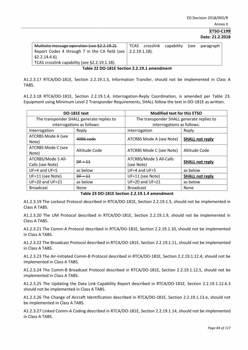
Multisite message operation (see §2.2.19.2). Report Codes 4 through 7 in the CA field (see §2.2.14.4.6). TCAS crosslink capability (see §2.2.19.1.18).
TCAS crosslink capability (see paragraph 2.2.19.1.18).
Table 22 DO-181E Section 2.2.19.1 amendment A1.2.3.17 RTCA/DO-181E, Section 2.2.19.1.3, Information Transfer, should not be implemented in Class A TABS. A1.2.3.18 RTCA/DO-181E, Section 2.2.19.1.4, Interrogation-Reply Coordination, is amended per Table 23. Equipment using Minimum Level 2 Transponder Requirements, SHALL follow the text in DO-181E as written.
DO-181E text Modified text for this ETSO
The transponder SHALL generate replies to interrogations as follows:
The transponder SHALL generate replies to interrogations as follows:
Interrogation Reply Interrogation Reply
ATCRBS Mode A (see Note)
4096 code ATCRBS Mode A (see Note) SHALL not reply
ATCRBS Mode C (see Note)
Altitude Code ATCRBS Mode C (see Note) Altitude Code
ATCRBS/Mode S All-Calls (see Note)
DF = 11 ATCRBS/Mode S All-Calls (see Note)
SHALL not reply
UF=4 and UF=5 as below UF=4 and UF=5 as below
UF=11 (see Note) DF = 11 UF=11 (see Note) SHALL not reply
UF=20 and UF=21 as below UF=20 and UF=21 as below
Broadcast None Broadcast None
Table 23 DO-181E Section 2.2.19.1.4 amendment
A1.2.3.19 The Lockout Protocol described in RTCA/DO-181E, Section 2.2.19.1.5, should not be implemented in Class A TABS.
A1.2.3.20 The UM Protocol described in RTCA/DO-181E, Section 2.2.19.1.9, should not be implemented in Class A TABS.
A1.2.3.21 The Comm-A Protocol described in RTCA/DO-181E, Section 2.2.19.1.10, should not be implemented in Class A TABS.
A1.2.3.22 The Broadcast Protocol described in RTCA/DO-181E, Section 2.2.19.1.11, should not be implemented in Class A TABS.
A1.2.3.23 The Air-Initiated Comm-B Protocol described in RTCA/DO-181E, Section 2.2.19.1.12.4, should not be implemented in Class A TABS.
A1.2.3.24 The Comm-B Broadcast Protocol described in RTCA/DO-181E, Section 2.2.19.1.12.5, should not be implemented in Class A TABS.
A1.2.3.25 The Updating the Data Link Capability Report described in RTCA/DO-181E, Section 2.2.19.1.12.6.3 should not be implemented in Class A TABS.
A1.2.3.26 The Change of Aircraft Identification described in RTCA/DO-181E, Section 2.2.19.1.13.e, should not be implemented in Class A TABS.
A1.2.3.27 Linked Comm-A Coding described in RTCA/DO-181E, Section 2.2.19.1.14, should not be implemented in Class A TABS.
ED Decision 2018/002/R
Annex II
ETSO-C199
Date: 21.2.2018
Page 85 of 117
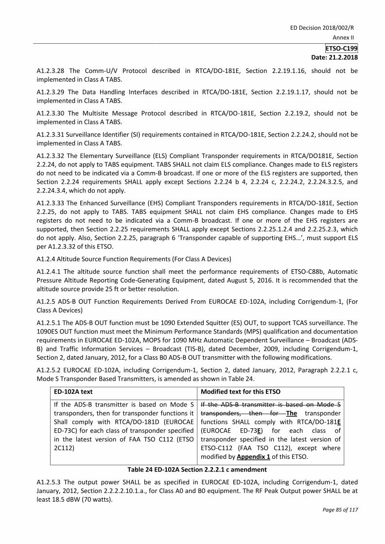
A1.2.3.28 The Comm-U/V Protocol described in RTCA/DO-181E, Section 2.2.19.1.16, should not be implemented in Class A TABS.
A1.2.3.29 The Data Handling Interfaces described in RTCA/DO-181E, Section 2.2.19.1.17, should not be implemented in Class A TABS.
A1.2.3.30 The Multisite Message Protocol described in RTCA/DO-181E, Section 2.2.19.2, should not be implemented in Class A TABS.
A1.2.3.31 Surveillance Identifier (SI) requirements contained in RTCA/DO-181E, Section 2.2.24.2, should not be implemented in Class A TABS.
A1.2.3.32 The Elementary Surveillance (ELS) Compliant Transponder requirements in RTCA/DO181E, Section 2.2.24, do not apply to TABS equipment. TABS SHALL not claim ELS compliance. Changes made to ELS registers do not need to be indicated via a Comm-B broadcast. If one or more of the ELS registers are supported, then Section 2.2.24 requirements SHALL apply except Sections 2.2.24 b 4, 2.2.24 c, 2.2.24.2, 2.2.24.3.2.5, and 2.2.24.3.4, which do not apply.
A1.2.3.33 The Enhanced Surveillance (EHS) Compliant Transponders requirements in RTCA/DO-181E, Section 2.2.25, do not apply to TABS. TABS equipment SHALL not claim EHS compliance. Changes made to EHS registers do not need to be indicated via a Comm-B broadcast. If one or more of the EHS registers are supported, then Section 2.2.25 requirements SHALL apply except Sections 2.2.25.1.2.4 and 2.2.25.2.3, which do not apply. Also, Section 2.2.25, paragraph 6 ‘Transponder capable of supporting EHS…’, must support ELS per A1.2.3.32 of this ETSO.
A1.2.4 Altitude Source Function Requirements (For Class A Devices)
A1.2.4.1 The altitude source function shall meet the performance requirements of ETSO-C88b, Automatic Pressure Altitude Reporting Code-Generating Equipment, dated August 5, 2016. It is recommended that the altitude source provide 25 ft or better resolution.
A1.2.5 ADS-B OUT Function Requirements Derived From EUROCAE ED-102A, including Corrigendum-1, (For Class A Devices)
A1.2.5.1 The ADS-B OUT function must be 1090 Extended Squitter (ES) OUT, to support TCAS surveillance. The 1090ES OUT function must meet the Minimum Performance Standards (MPS) qualification and documentation requirements in EUROCAE ED-102A, MOPS for 1090 MHz Automatic Dependent Surveillance – Broadcast (ADS-B) and Traffic Information Services – Broadcast (TIS-B), dated December, 2009, including Corrigendum-1, Section 2, dated January, 2012, for a Class B0 ADS-B OUT transmitter with the following modifications.
A1.2.5.2 EUROCAE ED-102A, including Corrigendum-1, Section 2, dated January, 2012, Paragraph 2.2.2.1 c, Mode S Transponder Based Transmitters, is amended as shown in Table 24.
ED-102A text Modified text for this ETSO
If the ADS-B transmitter is based on Mode S transponders, then for transponder functions it Shall comply with RTCA/DO-181D (EUROCAE ED-73C) for each class of transponder specified in the latest version of FAA TSO C112 (ETSO 2C112)
If the ADS-B transmitter is based on Mode S transponders, then for The transponder functions SHALL comply with RTCA/DO-181E (EUROCAE ED-73E) for each class of transponder specified in the latest version of ETSO-C112 (FAA TSO C112), except where modified by Appendix 1 of this ETSO.
Table 24 ED-102A Section 2.2.2.1 c amendment
A1.2.5.3 The output power SHALL be as specified in EUROCAE ED-102A, including Corrigendum-1, dated January, 2012, Section 2.2.2.2.10.1.a., for Class A0 and B0 equipment. The RF Peak Output power SHALL be at least 18.5 dBW (70 watts).
ED Decision 2018/002/R
Annex II
ETSO-C199
Date: 21.2.2018
Page 86 of 117
A1.2.5.4 Broadcast of the ADS-B Surface Position Messages defined in EUROCAE ED-102A including Corrigendum-1, Section 2.2.3.2.4 is optional.
A1.2.5.5 EUROCAE ED-102A including Corrigendum-1, Section 2.2.3.2.7.2, Aircraft Operational Status Messages, is amended as shown in Table 25.
ED-102A text Modified text for this ETSO
The ‘Aircraft Operational Status Message’ is used to provide the current status of the aircraft. The format of the Aircraft Operational Status Message shall be as specified in Figure 2-11, while further definition of each of the subfields is provided in the subsequent paragraphs.
The ‘Aircraft Operational Status Message’ is used to provide the current status of the aircraft. The format of the Aircraft Operational Status Message shall be as specified in Figure 2-11, while further definition of each of the subfields is provided in the subsequent paragraphs. Broadcast of Aircraft Operational Status Message subtype=1, Surface Messages, is optional.
Table 25 Aircraft Operational Status Message
A1.2.5.6 When TABS is installed with a position source meeting the Class B requirements of this ETSO and transmitting a valid position, the transmitted NIC SHALL be set to 6 (0.5 NM), reference EUROCAE ED-102A including Corrigendum-1, dated January, 2012, Section 2.2.8.1.6. The transmitted SIL SHALL be set to 1, (1x1E-3/ hr), reference EUROCAE ED-102A including Corrigendum-1, dated January, 2012, Section 2.2.5.1.40. When TABS is installed with a position source compliant with ETSO-C145, ETSO-C146 or ETSO-C196, NIC and SIL SHALL be set in accordance with EUROCAE ED-102A including Corrigendum-1, dated January, 2012. When the position is not valid, NIC and SIL SHALL be set to zero.
A1.2.5.7 The System Design Assurance (SDA), SHALL be set to 1, reference EUROCAE ED-102A, including Corrigendum-1, dated January, 2012, Section 2.2.5.1.50. The probability of an undetected fault causing transmission of false or misleading information SHALL be less than or equal to 1E-3.
A1.2.5.8 Navigation Accuracy Category for Position, (NACp) SHALL be derived from the Horizontal Figure of Merit (HFOM) in accordance with EUROCAE ED-102A, including Corrigendum-1, dated January, 2012, Section A.1.4.9.9, however, TABS Class B position sources may not provide HFOM directly. When HFOM is not available directly, HFOM SHALL be derived from Horizontal Dilution of Precision (HDOP) according to the following formula: HFOM = 2 * HDOP * User Equivalent Range Error (UERE), where the UERE is 6 metres. This UERE is based on typical single frequency (L1) receiver performance and an assumption of mid-latitude atmospheric propagation. Although the real-time UERE may fluctuate, this assumption is sufficient to support the TABS use case. (Ref Global Positioning System Signals, Measurements and Performance, by Pratap Misra and Per Enge, copyright 2001).
A1.2.5.9 When a TABS is installed with a position source meeting the Class B requirements of this ETSO and transmitting a valid position, the transmitted Navigation Accuracy Category for Velocity, (NACv) SHALL be set to 1 (10 m/s), reference EUROCAE ED-102A including Corrigendum-1, dated January, 2012, Section 2.2.5.1.19. When position is not valid, NACv SHALL be set to zero.
A1.2.5.10 Geometric Vertical Accuracy (GVA) SHALL be derived from Vertical Figure of Merit, (VFOM) in accordance with EUROCAE ED-102A including Corrigendum-1, dated January, 2012, Section 2.2.3.2.7.2.8. Class B position sources may not provide VFOM directly. When VFOM is not available directly, VFOM SHALL be derived from Vertical Dilution of Precision (VDOP) according to the following formula: VFOM = 2 * VDOP * UERE, where the UERE is 6 metres.
A1.2.5.11 The Type Code 31, Operational Status Message, subfield ‘Airborne Capability Class Code’, SHALL be changed to indicate the device is a TABS.

ED Decision 2018/002/R
Annex II
ETSO-C199
Date: 21.2.2018
Page 87 of 117
A1.2.5.11.1 The Operational Status Message SHALL be modified to indicate that it meets the performance standards of this ETSO. ED-102A, including Corrigendum-1, dated January, 2012, paragraph 2.2.18.4.7 and Figure 2-40, is modified by this ETSO. Message bits 53-54, (ME Bits 21-22), SHALL describe the capabilities of the TABS per Table 26. Set bit 54 to 1 (one) to indicate that either TABS Class A, Class B, or both classes of equipment are installed.
Bit 53 Bit 54 Description
0 0 Not TABS equipped
0 1 TABS Equipped
1 0 TABS device (reserved for future use)
1 1 TABS device (reserved for future use)
Table 26 ED-102A Airborne Capability Class Message format
A1.2.6 GNSS Position Source Function Requirements (For Class B Devices)
A1.2.6.1 Manufacturers may use commercial off-the-shelf (COTS) GNSS position sources to meet the performance of this ETSO as long as the sensor meets the requirements in this section. The position source shall be capable of using Satellite-Based Augmentation System (SBAS) corrections and health messages to exclude satellites from the position solution or to correct satellite range errors. In areas where the SBAS is available, the TABS shall use the SBAS corrections and health messages to exclude satellites from the position solution or to correct satellite range errors. In areas where the SBAS is not available or out of service, the TABS may continue to operate. The regional airspace authority will determine what operational impacts this may have on air-to-ground usage of TABS equipment. According to the FAA the GPS constellation experiences a significant ramp error approximately once a year. During these events, a chipset which uses the SBAS will, depending on the received SBAS messages, either correct or exclude the faulty satellite. Refer to RTCA/DO-229E, Minimum Operational Performance Standards for Global Positioning System/Satellite-Based Augmentation System Airborne Equipment, when interpreting SBAS-related requirements.
A1.2.6.2 The GNSS position source SHALL provide a GPS-only solution for use by the TABS ADS-B function. The FAA and EASA have not evaluated the performance of other GNSS systems for use in support of aviation intended functions. This ETSO will be updated once sufficient analysis has been done to show that other GNSS are appropriate for use by TABS equipment. Note, the GPS-only solution refers to the use of the GPS satellite constellation, it does not exclude augmentation of the GPS solution, such as provided by SBAS or GBAS systems.
A1.2.6.3 The GNSS horizontal position error SHALL not exceed 30 metres, 95th percentile, when the Horizontal Dilution of Precision (HDOP) is 2.5 or less. The GNSS position source SHALL either transmit a Horizontal Figure of Merit (95 %) (HFOM) or a HDOP metric.
Note: The 30 metre horizontal position fixing error requirement assumes a UERE of 6 metres, consistent with Section A1.2.5.8.
A1.2.6.4 Removed
A1.2.6.5 The GNSS position source SHALL be capable of transmitting horizontal velocity measurements more accurate than 10 m/s, 95th percentile.
A1.2.6.6 The GNSS position source SHALL not transmit false or misleading data in the presence of broadband interference. There is no minimum interference rejection requirement for TABS equipment and loss of position in the presence of interference is acceptable behaviour.
A1.2.6.7 The GNSS position source SHALL not use SBAS corrections when the SBAS satellite is broadcasting message type 0.
ED Decision 2018/002/R
Annex II
ETSO-C199
Date: 21.2.2018
Page 88 of 117
A1.2.6.8 The GNSS position source SHALL exclude satellites with UDREI=15 reported in the SBAS fast corrections.
A1.2.6.9 The GNSS position source SHALL apply SBAS fast and long term corrections when available.
A1.2.6.10 The GNSS position source SHALL be capable of transmitting geometric altitude, Height Above the Ellipsoid (HAE) measurements more accurate than 45 metres, 95th percentile when the Vertical Dilution of Precision (VDOP) is 3.7 or less. The GNSS position source SHALL either transmit a Vertical Figure of Merit (95 %) (VFOM) or a Vertical Dilution of Precision (VDOP) metric.
Note: The 45 metre vertical position fixing error requirement assumes a UERE of 6 metres, consistent with Section A1.2.5.10.
A1.2.7 Antenna Function Requirements
A1.2.7.1 The requirements for transponder antennas are specified in ETSO-C112e. The requirements for GNSS antennas are specified in ETSO-C190 and ETSO-C144a. The antennas should be designed to meet the performance specified in the applicable ETSO. However, the TABS may benefit significantly in installation costs from implementations where the antennas are integrated in the TABS equipment. Small degradations in antenna performance may be acceptable as a trade-off for installation cost.
A1.2.7.2 Antennas may be installed internally on aircraft that are transparent to radio frequencies. An internal antenna may not be appropriate on aircraft with a metal hull. If an antenna is installed internally, testing will need to be conducted to ensure the TABS is not negatively impacted and installation guidance must accompany the unit to ensure the system is properly fitted to the aircraft.
A1.2.7.3 Because TABS may be installed on a radio frequency (RF) transparent fuselage near a pilot or passenger, or in a cockpit in close proximity to a pilot or passenger, consideration must be given to antenna placement to ensure it does not pose a hazard to humans or combustible materials. Manufacturers must provide installation guidance describing the minimum safe distance the antenna can be to the nearest human body or if applicable, combustible material. Appendix 3 of this ETSO provides a more in-depth discussion of this subject based on FCC and European documents.
A1.2.8 Form factor and power
A1.2.8.1 An ideal implementation of the TABS would be a single integrated unit with minimal connections to the airframe, such as; mechanical mounting, power, and static air source. Where the equipment might be shared between multiple airframes, the mechanical mounting could incorporate an airframe specific configuration module (containing such items as the ICAO 24 bit aircraft address), and be designed such that no tools are required to remove or install the TABS.
A1.2.8.2 Low power consumption design is important. Designs specifically intended for long-term battery operation are ideal. If the TABS is battery powered, it should be designed to provide system integrity commensurate with the failure condition category / classification stated in paragraph 3.2.1.
Appendix 2. Test Requirements
A2 Testing Introduction
A2.1 Testing Intent
A2.1.1 This appendix provides an acceptable means to verify the major functions of the TABS.
A2.1.2 The TABS is not intended to accept and reply to any UF=11 All-Call interrogations. RTCA/DO-181E tests like 2.4.2.1 Step 6 that use the Mode S Only All-Call interrogation (UF=11) will need to use a different interrogation, such as a UF=0 interrogation.
A2.2 Testing Requirements

ED Decision 2018/002/R
Annex II
ETSO-C199
Date: 21.2.2018
Page 89 of 117
A2.2.1 The tests defined here are derived from tests in the reference documents or written here to ensure compliance with the intended capabilities of TABS equipment. These tests are one acceptable means to demonstrate the equipment meets the functional requirements defined in Appendix 1 of this ETSO. Functionality not modified by Appendix 1 should be verified by the test outlined in the applicable standards, e.g. RTCA/DO-181E.
A2.2.2 Table 27 provides notes in italics and parenthesis explaining how to read the tables that modify the text in the source documents.
(Source document reference) Modified text for this ETSO
(This is a copy of the original text from the source document. Material to be deleted from this original text is marked with strikethrough formatting.)
(This is the requirement for this ETSO. Modifications to the source text are marked in bold and underlined to assist in identifying changes).
Table 27 (Source document reference) (type of change)
A2.2.3 Testing Transponder Function Requirements Derived From DO-181E (For Class A Devices)
A2.2.3.1 Testing of the transponder function of the TABS should follow the tests outlined in document RTCA/DO-181E, Minimum Operational Performance Standards for Air Traffic Control Radar Beacon System/Mode Select (ATCRBS/Mode S) Airborne Equipment, dated March 17, 2011, Section 2.3, 2.4, and 2.5, with the following exceptions:
A2.2.3.1.1 Testing of Flight Crew Control Functions
A2.2.3.1.2 Testing should verify the requirements of RTCA/DO-181E, as modified by paragraph A1.2.3.1.2 of this ETSO have been properly incorporated.
A2.2.3.1.3 Testing should verify changes made to paragraph 2.1.7 a, in RTCA/DO-181E, per Section A1.2.3.1.3 have been properly incorporated.
A2.2.3.1.3.1 Testing should verify the requirements of A1.2.3.1.3, by performing the test outlined in RTCA/DO-181E Section 2.5.4.11. Test results should verify that the 4096 code can be set while on the ground. If the 4096 code can be set in flight, testing should verify the 4096 code can be set while in the air (weight-off-wheels condition) per RTCA/DO-181E Section 2.5.4.11.
A2.2.3.1.3.2 Testing should verify the requirements of A1.2.3.1.3, by performing the test outlined in RTCA/DO-181E Section 2.5.4.11. Testing should verify that a means of selecting and transmitting Mode 3/A code 7700 (emergency) is provided and tested per RTCA/DO-181E Section 2.5.4.11.
A2.2.3.1.3.3 Testing should verify the requirements of A1.2.3.1.3, by performing the test outlined in RTCA/DO-181E Section 2.5.4.11. Testing should also verify that a means of selecting and transmitting an alternate Mode 3/A codes is provided and tested per RTCA/DO-181E Section 2.5.4.11.
A2.2.3.1.4 Testing should verify the requirements of A1.2.3.1.4, by performing the test outlined in RTCA/DO-181E 2.5.4.3.b. Test results should verify aircraft without a means of determining air/ground state, reports in-the-air at all times. Aircraft with an automatic means to determine the air/ground state, must verify that the air/ground state is set properly. Perform the test outlined in RTCA/DO-181E 2.5.4.3.b. If capable of determining the air-ground state, test results should verify the aircraft reports in-the-air when in the air, and on-the-ground when on the ground.
A2.2.3.1.5 Testing should verify the requirements of A1.2.3.1.5, have been properly incorporated. If a means of selecting the Standby condition is provided, testing should verify return to normal operation from standby condition is within five seconds.

ED Decision 2018/002/R
Annex II
ETSO-C199
Date: 21.2.2018
Page 90 of 117
A2.2.3.1.6 Testing should verify the requirements of A1.2.3.1.6, have been properly incorporated. If a means of initiating the IDENT (SPI) feature is installed, testing shall verify it functions properly per RTCA/DO-181E Section 2.5.4.3. (see Also A1.2.3.5and A2.2.3.5)
A2.2.3.2 Testing Reply Rate Capability Changes
A2.2.3.2.1 This section provides test criteria for the reply rate changes based on assumptions made in Section A1.2.3.2.1.
A2.2.3.2.2 Testing should verify changes made to A1.2.3.2.2, have been correctly incorporated into TABS equipment.
A2.2.3.2.2.1 Testing should verify the requirements of A1.2.3.2.2.1, of this ETSO have been satisfied. Testing outlined in DO-181E, Section 2.3.2.2.3 step 1 should verify that the transponder be able to continuously generate at least 100 ATCRBS 15-pulse replies per second.
A2.2.3.2.2.2 Testing should verify the requirements of A1.2.3.2.2.2, of this ETSO have been satisfied. Testing outlined in DO-181E, Section 2.3.2.2.3 step 3 should verify that the transponder is capable of a peak reply rate of 150 ATCRBS 15-pulse replies per second for a duration of 100 milliseconds.
A2.2.3.2.2.3 Testing should verify changes made to RTCA/DO-181E Section 2.2.3.4.2.a have been correctly incorporated into TABS equipment per A1.2.3.2.2.3.
A2.2.3.2.2.3.1 Testing should verify the requirements of RTCA/DO-181E, Section 2.2.3.2.4.2.a, as modified by paragraph A1.2.3.2.2.3 of this ETSO have been satisfied. Testing outlined in DO-181E, Section 2.3.2.2.3 step 2 should verify that the transponder provide at least 29 short Mode S replies in any 1-second interval.
A2.2.3.2.2.3.2 Testing should verify the requirements of RTCA/DO-181E, Section 2.2.3.2.4.2.a, as modified by paragraph A1.2.3.2.2.3 of this ETSO have been satisfied. Testing outlined in DO-181E, Section 2.3.2.2.3 step 3 should verify that the transponder provide at least 10 short Mode S replies in a 100-millisecond interval.
A2.2.3.2.2.3.3 Testing should verify the requirements of RTCA/DO-181E, Section 2.2.3.2.4.2.a, as modified by paragraph A1.2.3.2.2.3 of this ETSO have been satisfied. Testing outlined in DO-181E, Section 2.3.2.2.3 step 4 should verify that the transponder provide at least 5 short Mode S replies in a 25-millisecond interval.
A2.2.3.2.2.3.4 Testing should verify the requirements of RTCA/DO-181E, Section 2.2.3.2.4.2.a, as modified by paragraph A1.2.3.2.2.3 of this ETSO have been satisfied. Testing outlined in DO-181E, Section 2.3.2.2.3 step 5 should verify that the transponder provide at least 3 short Mode S replies in a l.6-millisecond interval.
A2.2.3.2.2.4 Testing should verify changes made to RTCA/DO-181E Section 2.2.3.4.2.b have been correctly incorporated into TABS equipment per A1.2.3.2.2.4.
A2.2.3.2.2.4.1 Testing should verify the requirements of RTCA/DO-181E, Section 2.2.3.2.4.2.b, as modified by paragraph A1.2.3.2.2.4, of this ETSO have been satisfied. Testing outlined in DO-181E, Section 2.3.2.2.3 step 2 should verify that the transponder provide at least 10 of the 29 Mode S replies as long format replies in any 1-second interval.
A2.2.3.2.2.4.2 Testing should verify the requirements of RTCA/DO-181E, Section 2.2.3.2.4.2.b, as modified by paragraph A1.2.3.2.2.4, of this ETSO have been satisfied. Testing outlined in DO-181E, Section 2.3.2.2.3 step 3 should verify that the transponder provide at least 4 of the 10 Mode S replies as long format replies in a 100-millisecond interval.
A2.2.3.2.2.4.3 Testing should verify the requirements of RTCA/DO-181E, Section 2.2.3.2.4.2.b, as modified by paragraph A1.2.3.2.2.4, of this ETSO have been satisfied. Testing outlined in DO-181E, Section 2.3.2.2.3 step 4 should verify that the transponder provide at least 3 of the 5 Mode S replies as long format replies in a 25-millisecond interval.
ED Decision 2018/002/R
Annex II
ETSO-C199
Date: 21.2.2018
Page 91 of 117
A2.2.3.2.2.4.4 Testing should verify the requirements of RTCA/DO-181E, Section 2.2.3.2.4.2.b, as modified by paragraph A1.2.3.2.2.4, of this ETSO have been satisfied. Testing outlined in DO-181E, Section 2.3.2.2.3 step 5 should verify that the transponder provide at least 2 of the 4 Mode S replies as long format replies in a l.6-millisecond interval.
A2.2.3.3 Testing Reply Rate Limiting Changes
A2.2.3.3.1 Testing should verify the requirements of RTCA/DO-181E, Section 2.2.7.3.1, as modified by paragraph A1.2.3.3.1, of this ETSO have been satisfied. Testing outlined DO-181E Section 2.4.2.2.5 step 1 should be performed to verify the unit does not reply to Mode A interrogations.
A2.2.3.3.2 Testing should verify the requirements of RTCA/DO-181E, Section 2.2.7.3.1, as modified by paragraph A1.2.3.3.2 of this ETSO have been satisfied. Testing outlined in DO-181E Section 2.4.2.2.5 step 1 should be performed to verify the unit is capable of between 100 continuous ATCRBS Mode C replies per second and the maximum continuous rate of which the transponder is capable, or 200 replies per second, whichever is less, without regard to the number of pulses in each reply. Sensitivity reduction SHALL apply only to the receipt of ATCRBS interrogations.
A2.2.3.4 Testing should verify the requirements of RTCA/DO-181E, Section 2.2.13.1.2 c, as modified by paragraph A1.2.3.4 of this ETSO have been satisfied. Testing should show airborne status is set to in the air unless the aircraft is air/ground determination capable. If the aircraft can determine air/ground state, testing should show this capability determines on the ground when on the ground and in the air when in the air.
A2.2.3.5 Testing should verify the requirements of RTCA/DO-181E, Section 2.2.13.1.2 d, as modified by paragraph A1.2.3.5 of this ETSO have been satisfied. If the aircraft is capable of providing SPI, follow the test outlined in A2.2.3.1.6 of the ETSO to verify it functions properly per RTCA/DO-181E Section 2.5.4.3. (See also, Section A1.2.3.1.6 and A2.2.3.1.6
A2.2.3.6 Testing should verify the requirements of RTCA/DO-181E, Section 2.2.13.1.2 e, as modified by paragraph A1.2.3.6 of this ETSO have been satisfied. Testing should show the Aircraft ID loaded while on the ground is broadcast. If aircraft ID can be changed in flight, testing should verify aircraft ID can be changed in flight and the new aircraft ID is broadcast.
A2.2.3.7 Testing of Interrogation Acceptance Protocol Changes (All-Call reply capability)
A2.2.3.7.1 Except where noted here, testing of the Interrogation Acceptance Protocol capability should follow that called out in RTCA/DO-181E. Testing of the Interrogation Acceptance Protocol capability should be modified from those called out in RTCA/DO-181E to meet the changes made in A1.2.3.7.1.
A2.2.3.7.2 Testing should verify the requirements of RTCA/DO-181E, Section 2.2.18.2.2 b, as modified by paragraph A1.2.3.7.2 of this ETSO have been satisfied. Various tests in RTCA DO-181E Section 2.4 utilize the Mode S Only All-Call interrogation and expected reply to execute the test procedure. A discrete interrogation should be used as a substitute for these test procedures. Testing outlined in RTCA/DO-181E, Section 2.5.4.2 should verify that UF=11 interrogations are not accepted.
A2.2.3.7.3 Testing should verify the requirements of RTCA/DO-181E, Section 2.2.18.2.2 c, as modified by paragraph A1.2.3.7.3 of this ETSO have been satisfied. Testing outlined in RTCA/DO-181E, Section 2.5.4.2 should verify that an ATCRBS/Mode S All-Call interrogation (1.6 microseconds P4) is not accepted. The pulse decoder tests in Section 2.4.2.5 for ATCRBS/Mode S All-Call interrogation acceptance shall be modified to verify no ATCRBS/Mode S All-Call interrogations that meet the criteria for acceptance in RTCA DO-181E, Section 2.2.6.2, produce a reply.
A2.2.3.8 Testing of the requirements of RTCA/DO-181E, Interrogation Acceptance Protocol, per Section 2.5.4.4 and 2.5.4.5 are not required per A1.2.3.8 of this ETSO.

ED Decision 2018/002/R
Annex II
ETSO-C199
Date: 21.2.2018
Page 92 of 117
A2.2.3.9 Testing of the requirements of RTCA/DO-181E, Stochastic All-Calls, per 2.5.4.13 is not required per A1.2.3.9 of this ETSO.
A2.2.3.10 Testing should verify the modified Mode S MTL requirements added to RTCA/DO-181E, per Section A1.2.3.10. Test to ensure paragraph 2.2.18.2.2 L, and 2.2.18.2.2 m, have been properly incorporated.
A2.2.3.10.1 Testing outlined in RTCA/DO-181E, Section 2.4.2 should verify that ATCRBS Mode A interrogations (P1-P3 spacing 8 microseconds) are not accepted per A1.2.3.10.1. Various tests in RTCA DO-181E Section 2.4 utilize Mode A interrogations to execute the test procedure. Mode C interrogations should be used as a substitute for these test procedures. The pulse decoder tests in DO-181E, Section 2.4.2.5 for Mode A interrogation acceptance shall be modified to verify that no Mode A interrogations that meet the criteria for acceptance in DO-181E, Section 2.2.6.2 produce a reply. Requirement for recovery from a Mode A interrogation per A1.2.3.10.1 shall be tested according to DO-181E Section 2.4.2.6, Step 1 except using a Mode A interrogation from the master and a Mode C interrogation from the slave.
A2.2.3.10.2 Testing should verify the requirements added to RTCA/DO-181E, paragraph 2.2.18.2.2 m, have been properly incorporated per Section A1.2.3.10.2. Verify the requirement added by this ETSO, by performing the test procedure in RTCA/DO-181E, Section 2.4.2.1. step 6, using a UF=0 to verify the Mode S MTL in Section 2.2.2.4 b and UF=4, 5, 20 and 21 to verify the modified MTL per A1.2.3.10.2.
A2.2.3.11 Testing should verify the requirements of RTCA/DO-181E, Interrogation Reply Coordination, Section 2.2.18.2.3, as modified by A1.2.3.11 of this ETSO are satisfied. Testing outlined in DO-181E Section 2.5.4.2 shall be modified to verify the unit does not reply to ATCRBS Mode A interrogations. Test ATCRBS Mode A/Mode S All-Calls, ATCRBS Mode C/Mode S All-Calls or UF=11 interrogations per testing outlined in A2.2.3.7 and A2.2.3.10.
A2.2.3.12 Testing of RTCA/DO-181E, Lockout Protocol, Section 2.2.18.2.4, is not required since TABS devices do not reply to All-Call interrogations per A1.2.3.12 of this ETSO. Testing using interrogations in RTCA/DO-181E Section 2.5.4.4 should be performed to verify the unit properly replies to interrogations containing lockout commands from ground interrogations.
A2.2.3.13 Testing of RTCA/DO-181E, Multisite Lockout Protocol, Section 2.2.18.2.5, is not required since TABS devices do not reply to All-Call interrogations per A1.2.3.13 of this ETSO. Testing using interrogations in RTCA/DO-181E Section 2.5.4.5 should be performed to verify the unit properly replies to interrogations containing multisite lockout commands from ground interrogations.
A2.2.3.14 Testing should verify the requirements of RTCA/DO-181E, Flight Status and Vertical Status Protocols, Section 2.2.18.2.7, as modified by A1.2.3.14 of this ETSO are satisfied. Testing outlined in DO-181E Section 2.5.4.7 should be performed to verify the unit sets the flight status bits properly consistent with the capabilities provided for Mode 3/A code entry per A1.2.3.1.3.
A2.2.3.15 Testing the requirement of RTCA/DO-181E, All-Call Reply Protocol, Section 2.2.18.2.9, as modified by A1.2.3.15 is not required. Testing outlined in DO-181E Section 2.5.4.8 does not need to be performed since the TABS does not support the All-Call Protocol.
A2.2.3.16 Testing should verify the Level 2 Transponder Requirements of RTCA/DO-181E, Minimum Level 2 Transponder Requirements, Section 2.2.19.1, as modified by A1.2.3.16 of this ETSO are satisfied. Testing outlined in RTCA/DO-181E Section 2.5.3 should be performed to verify the unit performs per design specifications. Also, testing outlined in RTCA/DO-181E section 2.5.4.17 should be performed to verify the unit does not process DF=16 messages.
A2.2.3.17 No test is required to verify the requirements of RTCA/DO-181E, Information Transfer, Section 2.2.19.1.3, per A1.2.3.17.

ED Decision 2018/002/R
Annex II
ETSO-C199
Date: 21.2.2018
Page 93 of 117
A2.2.3.18 Testing should verify the requirements of RTCA/DO-181E, Interrogation-Reply Coordination, Section 2.2.19.1.4, as modified by A1.2.3.18 are met. Use tests in A2.2.3.7 and A2.2.3.10 in this ETSO to verify the TABS does not reply to ATCRBS Mode A, ATCRBS/Mode S All Calls and UF=11 interrogations.
A2.2.3.19 Testing of the requirements of RTCA/DO-181E, Lockout Protocol, Section 2.2.19.1.5, per Section 2.5.4.4, are not required per A1.2.3.19 of this ETSO. Testing should verify the TABS does not perform the UM Protocol per RTCA/DO-181E Section 2.5.4.18.
A2.2.3.20 Since TABS do not support the Comm-B protocol except for GICB extraction requests, the requirements of RTCA/DO-181E, UM Protocol, Section 2.2.19.1.9, do not apply, per A1.2.3.20. Using a subset of the interrogations identified in RTCA/DO-181E Section 2.5.4.18, select 12 interrogations with UF 4, 5, 20 and 21 and containing DI=0, 1 and 7 and verify that the reply contains UM field of ZERO.
A2.2.3.21 Testing of the requirements of RTCA/DO-181E, Comm-A Protocol, Section 2.2.19.1.10, per Section 2.5.4.15 are not required per A1.2.3.21 of this ETSO. Testing should verify the TABS does not perform the Com-A Protocol per RTCA/DO-181E Section 2.5.4.15.
A2.2.3.22 Testing of the requirements of RTCA/DO-181E, Broadcast Protocol, Section 2.2.19.1.11, as modified by A1.2.3.22 is not required since TABS do not support this protocol.
A2.2.3.23 Testing of the requirements of RTCA/DO-181E, Air-Initiated Comm-B Protocol, Section 2.2.19.1.12.4, per Section 2.5.4.18 is not required per A1.2.3.23. To verify GICB extraction requirements, perform the portion of the test procedure of RTCA/DO-181E, Section 2.5.4.18 using interrogation patterns 1 to 24, to test the transponder in state 1 of the test matrix to verify proper reply content.
A2.2.3.24 Testing the requirements of RTCA/DO-181E, Comm-B Broadcast Protocol, Section 2.2.19.1.12.5, per 2.5.4.21 is not required per A1.2.3.24.
A2.2.3.25 Testing should verify the requirements of RTCA/DO-181E, Updating the Data Link Capability Report, Section 2.2.19.1.12.6.3, as modified by A1.2.3.25. Testing should verify the TABS does not perform the Updating the Data Link Capability Report per RTCA/DO-181E, Section 2.5.4.33.
A2.2.3.26 Testing should verify the requirements of RTCA/DO-181E, Change of Aircraft Identification, Section 2.2.19.1.13 e, as modified by A1.2.3.26. Testing should verify the TABS does not perform the Change of Identification per RTCA/DO-181E, Section 2.5.4.19.
A2.2.3.27 Testing the requirements of RTCA/DO-181E, Linked Comm-A Coding, Section 2.2.19.1.14, per 2.5.4.15, is not required per A1.2.3.27.
A2.2.3.28 Testing the requirements of RTCA/DO-181E, Comm-U/V Protocol, Section 2.2.19.1.16, per 2.5.4.17, as modified by A1.2.3.28 is not required.
A2.2.3.29 Testing the requirements of RTCA/DO-181E, Data Handling Interfaces, Section 2.2.19.1.17, per 2.5.4.20, as modified by A1.2.3.29 is not required.
A2.2.3.30 Testing the requirements of RTCA/DO-181E, Multisite Message Protocol, Section 2.2.19.2, per Section 2.5.4.5, as modified by A1.2.3.30 is not required.
A2.2.3.31 Testing the requirements of RTCA/DO-181E, Surveillance Identifier (SI), Section 2.2.24.2, per 2.6.2, as modified by A1.2.3.31 is not required.
A2.2.3.32 Testing the requirements of RTCA/DO-181E, Elementary Surveillance Capability, Section 2.2.24 as modified by A1.2.3.32 is not required. If one or more ELS registers are supported, test per RTCA/DO-181E, Section 2.6.
A2.2.3.33 Testing the requirements of RTCA/DO-181E, Enhanced Surveillance Capability, Section 2.2.25.3.2, as modified by A1.2.3.33 is not required. If the unit is Enhanced Surveillance Capability capable test per RTCA/DO-181E, Section 2.7.

ED Decision 2018/002/R
Annex II
ETSO-C199
Date: 21.2.2018
Page 94 of 117
A2.2.4 Testing Altitude Source Function Requirements
A2.2.4.1 Testing of the Altitude Source Function should follow that called out in ETSO-C88b, Automatic Pressure Altitude Reporting Code Generating Equipment, dated August 5, 2016.
A2.2.5 Testing ADS-B OUT Function Requirements (For Class A Devices)
A2.2.5.1 Testing should verify the ADS-B system performs its intended function per EUROCAE ED-102A, MOPS for 1090 MHz Automatic Dependent Surveillance – Broadcast (ADS-B) and Traffic Information Services – Broadcast (TIS-B), dated December, 2009, including Corrigendum-1, dated January, 2012, except as modified by Section A1.2.5. Testing should follow the tests outlined in EUROCAE ED-102A, including Corrigendum-1, dated January, 2012, Section 2.3 and 2.4 with the following exceptions:
A2.2.5.2 Per Section A1.2.5.2, testing of transponder functions should follow the requirements in Section A1.2.3 and A2.2.3 of this ETSO.
A2.2.5.3 Testing should verify the System RF Peak Power Output has a peak output level of at least 18.5 dBW (70 watts) per A1.2.5.3, reference EUROCAE ED-102A, including Corrigendum-1, dated January, 2012, RF Peak Power, Section 2.2.2.2.10.1 a. Testing outlined in ED-102A, Section 2.3.2.2.6.1 step 5 should verify the unit under test provides a peak output power level of at least 18.5 dBW (70 watts).
A2.2.5.4 If the optional ADS-B Surface Position Messages function is provided, per Section, A1.2.5.4, testing should verify the ADS-B Surface Position Message is correctly populated and broadcast per EUROCAE ED-102A Section 2.4.3.2.1.2.2.
A2.2.5.5 If the optional Typecode 31, subtype 1, Aircraft Operational Status Messages is provided per Section A1.2.5.5, testing should verify the Aircraft Operational Status Messages is correctly populated and broadcast per EUROCAE ED-102A Section 2.4.3.2.7.2
A2.2.5.6 Per Section A1.2.5.6, testing should verify that NIC=6, and SIL=1 when using position from a Class B position source using test procedures in EUROCAE ED-102A, including Corrigendum-1, dated January, 2012, Sections 2.4.8.1.5, 2.4.5.1.40.
A2.2.5.7 Testing should verify the System Design Assurance (SDA) is set to 1 to verify the requirement in Section A1.2.5.7, reference EUROCAE ED-102A, including Corrigendum-1, dated January, 2012, System Design Assurance (SDA), Section 2.2.5.1.50.
A2.2.5.8 Per Section A1.2.5.8, testing should verify that Navigation Accuracy Category for Position (NACp) is set according to EUROCAE ED-102A including Corrigendum-1, dated January, 2012, Section 2.4.3.2.7.1.3.8. Testing should verify that the NACp is set appropriately when the position source is providing HDOP and not HFOM.
A2.2.5.9 If a TABS Class B position source is installed, verify Navigation Accuracy Category Velocity (NACv) is set to 1 (10 m/s) per A1.2.5.9.
A2.2.5.10 Verify Geometric Vertical Accuracy (GVA) is set per A1.2.5.10. Testing outlined in EUROCAE ED-102A, including Corrigendum-1, dated January, 2012, Section 2.4.3.2.7.2.8 should verify GVA is set appropriately when the position source is providing VDOP and not VFOM.
A2.2.5.11 Verify Type Code 31, Airborne Capability Class Message indicates the unit under test is a TABS per A1.2.5.11.
A2.2.6 Testing of GNSS Position Source Function Requirements (For Class B Devices)
A2.2.6.1 A TABS incorporating a position source that is compliant with ETSO-C129, ETSO-C145, ETSO-C146 or ETSO-C196 must also meet the additional ADS-B criteria defined in AMC1 ACNS.D.ADSB.070 of CS-ACNS, to include any required testing. GNSS position sources that are not compliant with an existing GNSS ETSO will need to meet the requirements in paragraph A1.2.6 of this ETSO and verify it meets the minimum

ED Decision 2018/002/R
Annex II
ETSO-C199
Date: 21.2.2018
Page 95 of 117
requirements by performing the tests outlined in Section A2.2.6 of this ETSO. The following tests were derived from a reduced set of requirements and associated tests found in RTCA/DO-229E.
A2.2.6.2 GPS Only Solution.
A2.2.6.2.1 Per paragraph A1.2.6.2, verify that the position source provides a GPS-SBAS or GPS Only solution for use by Class A TABS.
A2.2.6.3 Position Accuracy Tests.
A2.2.6.3.1 Two tests are used to verify the horizontal position accuracy to ensure the requirement in paragraph A1.2.6.3 is met. The first test is a 24-hour static scenario using live satellite signals. The second test uses a GNSS simulator to generate a scenario incorporating both static and dynamic aircraft manoeuvers.
A2.2.6.3.2 24 Hour Accuracy Test.
A2.2.6.3.2.1 The equipment SHALL be tested over a 24-hour period using live GPS satellite signals at a surveyed location. The equipment SHALL use an antenna representative of what will be used in an actual airborne installation. The horizontal position error SHALL be computed for each position estimate output by the equipment.
A2.2.6.3.2.2 Monitor the sensor provided HFOM and VFOM, or HFOM and VFOM derived from the sensor provided HDOP and VDOP per paragraphs A1.2.5.8 and A1.2.5.10. In order to pass the test, the horizontal position error must be less than 30 metres for at least 95 % of the samples and the horizontal accuracy reported must be greater than the actual position error for at least 95 % of the samples. In order to pass the test, the vertical position error must be less than 45 metres for at least 95 % of the samples and the vertical accuracy reported must be greater than the actual position error for at least 95 % of the samples.
A2.2.6.3.2.3 The horizontal position error SHALL not exceed 0.5 NM at any time during the test.
A2.2.6.3.2.4 Only those position outputs that are reported as valid by the equipment need to be considered for the accuracy evaluation. In order to pass the test, 99.9 % of the position outputs must be reported as valid, excluding those position reports prior to the first position fix.
A2.2.6.3.3 GPS Simulator-based Accuracy Tests.
A2.2.6.3.3.1 The equipment SHALL be tested using a GPS simulator scenario that includes both static and dynamic aircraft manoeuvers. The horizontal and vertical position errors SHALL be computed for each position estimate output by the equipment.
A2.2.6.3.3.2 Monitor the sensor provided HFOM and VFOM, or HFOM and VFOM derived from the sensor provided HDOP and VDOP per paragraphs A1.2.5.8 and A1.2.5.10. In order to pass the test, the horizontal position error must be less than 30 metres for at least 95 % of the samples and the horizontal accuracy reported must be greater the actual position error for at least 95 % of the samples. In order to pass the test, the vertical position error must be less than 45 metres for at least 95 % of the samples and the vertical accuracy reported must be greater than the actual position error for at least 95 % of the samples.
A2.2.6.3.3.3 The horizontal position error SHALL not exceed 0.5 NM at any time during the test.
A2.2.6.3.3.4 Simulator Scenario Details
A2.2.6.3.3.4.1 Only those position outputs that are reported as valid by the equipment need to be considered for the accuracy evaluation. In order to pass the test, 99.9 % of the position outputs must be reported as valid, excluding those position reports prior to the first position fix.
A2.2.6.3.3.4.2 The simulator scenario SHALL use the standard 24 satellite constellation in RTCA/DO-229E Appendix B. The initial position and time should be chosen to ensure the satellite geometry supports the test Pass/Fail criteria and the HDOP is close to 2.5 and VDOP is close to 3.7.
A2.2.6.3.3.4.3 The simulation SHALL include both stationary and dynamic portions, as follows:

ED Decision 2018/002/R
Annex II
ETSO-C199
Date: 21.2.2018
Page 96 of 117
A2.2.6.3.3.4.3.1 At least 10 minutes of stationary position.
A2.2.6.3.3.4.3.2 A sequence of different manoeuvers, including acceleration to a constant velocity, climbs, descents, and turns.
A2.2.6.3.3.4.3.2.1 A series of turns should be included to ensure a constantly changing velocity to expose any effects of filtering on the position output.
A2.2.6.3.3.4.3.3 At least 10 minutes of accelerated manoeuvers SHALL be simulated.
A2.2.6.3.3.4.3.4 Aircraft dynamics are as follows: ground speed = 200 kt, horizontal acceleration=0.58 g, vertical acceleration of 0.5 g.
A2.2.6.3.3.4.4 The simulated satellite signals SHALL be set to -134 dBm while position measurements are taken. Signal powers may be increased at the beginning of the scenario to allow for initial acquisition.
A2.2.6.3.3.4.5 Simulated signals SHALL include ranging errors for atmospheric effects (troposphere and ionosphere) that adhere to approved models. Refer to DO-229E, Appendix A, Section A.4.2.4 and IS-GPS-200G dated September 5, 2012.
A2.2.6.3.3.4.6 No interference needs to be simulated.
2.2.6.4 Reserved
A2.2.6.5 Velocity Accuracy Tests.
A2.2.6.5.1 The velocity accuracy tests specified AC 20-138D Appendix 4, Sections 4-2, 4-3 and 4-4 SHALL be performed per the requirement in A1.2.6.5 and show the unit provides an accuracy of 10 m/s or less, at least 95 % of the time. It is assumed that the GPS position source does not provide a velocity accuracy output and the TABS will broadcast NACv = 1. Only the tests required to demonstrate a NACv = 1 need be run.
A2.2.6.6 Interference Tests.
A2.2.6.6.1 The equipment SHALL be tested using simulated GPS signals mixed with an interfering signal of gradually increasing power until the equipment loses position to verify the requirement outlined in paragraph A1.2.6.6. The horizontal position accuracy will be evaluated.
A2.2.6.6.2 Simulator Scenario Details.
A2.2.6.6.2.1 Use the same simulator scenario set up found in A2.2.6.3.3.4 with the following exceptions:
A2.2.6.6.2.2 The interfering signal SHALL be broadband noise with bandwidth of 20 MHz centred on 1575.42 MHz. The initial power spectral density SHALL be -170.5 dBm/Hz (-97.5 dBm total power).
A2.2.6.6.2.3 The scenario may to be extended to allow sufficient time for increasing interference power.
A2.2.6.6.3 Test Procedure
A2.2.6.6.3.1 Step 1: The interfering signal SHALL initially be turned off.
A2.2.6.6.3.2 Step 2: The simulator scenario SHALL be engaged and the satellites’ RF SHALL be turned on.
A2.2.6.6.3.3 Step 3: The equipment SHALL be powered on and initialized. It is assumed that the receiver has obtained a valid almanac for the simulator scenario to be tested prior to conducting these tests.
A2.2.6.6.3.4 Step 4: The receiver SHALL be allowed to reach steady state. When the receiver has reached steady state, an interfering broadband noise signal of -170.5 dBm/Hz SHALL be applied.
A2.2.6.6.3.5 Step 5: The interference power SHALL be maintained until the accuracy has reached steady-state. Position measurements and validity indications SHALL be recorded during this interval.
A2.2.6.6.3.6 Step 6: The power of the interfering signal SHALL be increased by 2 dB and maintained for 200 seconds.
ED Decision 2018/002/R
Annex II
ETSO-C199
Date: 21.2.2018
Page 97 of 117
A2.2.6.6.3.7 Step 7: Go to Step 5 and repeat until the receiver is unable to maintain a position fix.
A2.2.6.6.4 Pass/Fail Criteria
A2.2.6.6.4.1 The horizontal position errors SHALL be computed for each position estimate output by the equipment.
A2.2.6.6.4.2 The horizontal position error SHALL not exceed 0.5 NM at any time during the test.
A2.2.6.6.4.3 Only those position outputs that are reported as valid by the equipment need to be considered for the accuracy evaluation. There is no minimum interference rejection requirement for TABS equipment and loss of position in the presence of interference is acceptable behaviour.
A2.2.6.7 Verification of SBAS Message Type 0
A2.2.6.7.1 Test to verify the GNSS position source does not use SBAS corrections when the SBAS satellite is broadcasting message type 0 per A1.2.6.7.
A2.2.6.7.2 Simulator Scenario Details
A2.2.6.7.2.1 The simulator scenario SHALL use the standard 24 satellite constellation in RTCA/DO-229E Appendix B
A2.2.6.7.2.2 A single SBAS satellite SHALL be simulated with a fast corrections (MT 2-5) update rate of 6 seconds.
A2.2.6.7.2.3 At 500 seconds into the scenario, the SBAS satellite SHALL start broadcasting message type 0 for 60 seconds. The message type 0 broadcast SHALL contain message type 2 data (if appropriate for the SBAS service being simulated).
A2.2.6.7.2.4 The scenario SHALL have a static user position.
A2.2.6.7.2.5 The simulated satellite signals SHALL be set to a nominal power level (-128 dBm).
A2.2.6.7.2.6 Simulated signals SHALL include ranging errors for atmospheric effects (troposphere and ionosphere) that adhere to approved models. Refer to DO-229E Appendix A Section A.4.2.4 and IS-GPS-200G dated September 5, 2012.
A2.2.6.7.2.7 No interference needs to be simulated.
A2.2.6.7.3 Test Procedure
A2.2.6.7.3.1 Step 1: The simulator scenario SHALL be engaged and the satellites’ RF SHALL be turned on.
A2.2.6.7.3.2 Step 2: The equipment SHALL be powered on and initialized. It is assumed that the receiver has obtained a valid almanac for the simulator scenario to be tested prior to conducting the tests.
A2.2.6.7.3.3 Step 3: Monitor the receiver output for the indication of SBAS use. Verify that the receiver indicates that SBAS is not in use before an SBAS satellite has been acquired.
A2.2.6.7.3.4 Step 4: Allow the receiver to reach steady state navigation. Verify that the receiver indicates that SBAS is in use before proceeding to the next step.
A2.2.6.7.3.5 Step 5: 500 seconds into the scenario, the SBAS satellite SHALL start broadcasting message type 0.
A2.2.6.7.3.6 Step 6: Monitor the receiver output for the indication of SBAS use. Verify that the receiver indicates that SBAS is not used within 8 seconds.
A2.2.6.8 Exclusion of satellites identified by SBAS as unhealthy
A2.2.6.8.1 Test to verify the GNSS position source excludes satellites with UDREI=15 reported in the SBAS fast corrections per A1.2.6.8. The ability of the position source to exclude unhealthy satellites based on the SBAS

ED Decision 2018/002/R
Annex II
ETSO-C199
Date: 21.2.2018
Page 98 of 117
UDREI will be tested by injecting a ramp error on a satellite measurement and subsequently broadcasting a SBAS UDREI of 15 (‘do not use’) for that satellite.
A2.2.6.8.2 UDREI = 15 in fast corrections message (MT 2-5, 24)
A2.2.6.8.2.1 The equipment SHALL be tested to verify that the UDREI data contained in the SBAS fast corrections messages (MT 2-5, 24) is used to exclude unhealthy satellites.
Note: The test does not assume that the receiver outputs an indication that the unhealthy satellite has been removed from the position solution. Instead it uses a pass criteria based on horizontal position error.
A2.2.6.8.2.2 Simulator Scenario Details
A2.2.6.8.2.2.1 The simulator scenario SHALL use the standard 24 satellite constellation in RTCA/DO-229E Appendix B.
A2.2.6.8.2.2.2 A single SBAS satellite SHALL be simulated with a fast corrections (MT 2-5, 24) update rate of 6 seconds. The integrity information message (MT 6) SHALL not be broadcast.
A2.2.6.8.2.2.3 The simulation start time and location SHALL be such that the resulting HDOP is close to 5.0.
A2.2.6.8.2.2.4 The simulation SHALL use nominal aircraft dynamics, defined to be ground speed = 200 kt and horizontal acceleration = 0.58 g. These dynamics can be simulated as a series of turns.
A2.2.6.8.2.2.5 The scenario SHALL allow the receiver time to achieve steady state navigation before introducing any satellite errors.
A2.2.6.8.2.2.6 The scenario SHALL introduce a ramp error on each simulated GPS satellite individually, as follows:
A2.2.6.8.2.2.6.1 Step 1: A 5 m/s ramp error SHALL be introduced on the simulated GPS satellite.
A2.2.6.8.2.2.6.2 Step 2: Six seconds after the introduction of the ramp error, the simulated SBAS satellite SHALL broadcast a UDREI of 15 for the GPS satellite in the fast correction message.
A2.2.6.8.2.2.6.3 Step 3: The ramp error SHALL be applied until one of the following conditions occur:
— The horizontal position error of a valid position output exceeds 0.5 NM; or
— The ramp error exceeds 2 000 m; or
— The affected GPS satellite is excluded from the solution.
A2.2.6.8.2.2.6.4 Step 4: Allow the receiver time to return to steady state before repeating steps 1 to 3 on the next satellite.
A2.2.6.8.2.2.7 The simulated satellite signals SHALL be set to -134 dBm while position measurements are taken. Signal powers may be increased at the beginning of the scenario to allow for initial acquisition.
A2.2.6.8.2.2.8 Simulated signals SHALL include ranging errors for atmospheric effects (troposphere and ionosphere) that adhere to approved models. Refer to DO-229E, Appendix A, Section A.4.2.4 and IS-GPS-200G dated September 5, 2012.
A2.2.6.8.2.2.9 No interference needs to be simulated.
A2.2.6.8.2.3 Pass/Fail Criteria
A2.2.6.8.2.3.1 The test SHALL be run on two different space-time scenarios. The two scenarios SHALL be sufficiently separated to ensure that different satellite geometry is presented to the receiver.
A2.2.6.8.2.3.2 The horizontal position errors SHALL be computed for each position estimate output by the equipment during the test.
ED Decision 2018/002/R
Annex II
ETSO-C199
Date: 21.2.2018
Page 99 of 117
A2.2.6.8.2.3.3 The horizontal position error SHALL not exceed 0.5 NM at any time during the test.
A2.2.6.8.2.3.4 Only those position outputs that are reported as valid by the equipment need to be considered for the accuracy evaluation.
A2.2.6.9 Testing GNSS Position Source SBAS Fast and Long Term Corrections
A2.2.6.9.1 Application of Fast Corrections (MT 2-5, 24) and Long-Term Corrections (MT 24, 25) The equipment SHALL be tested to verify that fast corrections and long-term corrections are applied properly per A1.2.6.9.
A2.2.6.9.2 Simulator Scenario Details
A2.2.6.9.2.1 The simulator scenario SHALL use the standard 24 satellite constellation in RTCA/DO-229E Appendix B.
A2.2.6.9.2.2 A single SBAS satellite SHALL be simulated with a fast corrections (MT 2-5, 24) update rate of 6 seconds and standard long-term corrections (MT 24, 25) update rate of 120 seconds.
A2.2.6.9.2.3 The simulation start time and location SHALL be such that the resulting HDOP is close to 5.0.
A2.2.6.9.2.4 The simulation SHALL use nominal aircraft dynamics, defined to be ground speed = 200 kt and horizontal acceleration = 0.58 g. These dynamics can be simulated as a series of turns.
A2.2.6.9.2.5 The scenario SHALL introduce a bias and ramp error on a single satellite selected so that the range error will result in the maximum horizontal position error if not corrected by SBAS. The SBAS long-term corrections will be applied to correct the bias error. At each 6 seconds update, SBAS fast corrections will be provided to correct the ramp error for the affected satellite, as follows:
A2.2.6.9.2.5.1 Step 1: A 70 metre bias SHALL be introduced on the simulated GPS satellite. Provide SBAS long-term corrections to correct the bias term. The bias magnitude was chosen to approximate the maximum value that can be corrected by the δaf0 term in a type 25 message (using velocity code 0).
A2.2.6.9.2.5.2 Step 2: Start the scenario broadcasting MT25 with the correction for the bias error introduced on the selected satellite.
A2.2.6.9.2.5.3 Step 3: Allow the receiver time to acquire the GPS and SBAS satellites and obtain a steady-state differential fix, including sufficient time to acquire a type 25 message for the selected GPS satellite.
A2.2.6.9.2.5.4 Step 4: Inject a 5 m/s ramp error on the selected satellite in the same direction as the bias error.
A2.2.6.9.2.5.5 Step 5: At each 6 second update, provide SBAS fast corrections equivalent to the size of the growing ramp error.
A2.2.6.9.2.5.6 Step 6: The ramp error SHALL be applied until the ramp error plus bias error reaches 325 metres. Maintain the error of 325 metres for 5 minutes.
A2.2.6.9.2.6 The simulated satellite signals SHALL be set to -134 dBm while position measurements are taken. Signal powers may be increased at the beginning of the scenario to allow for initial acquisition.
A2.2.6.9.2.7 Simulated signals SHALL include ranging errors for atmospheric effects (troposphere and ionosphere) that adhere to approved models. Refer to DO-229E Appendix A Section A.4.2.4 and IS-GPS-200G dated September 5, 2012.
A2.2.6.9.2.8 No interference needs to be simulated.
A2.2.6.9.3 Pass/Fail Criteria
A2.2.6.9.3.1 The horizontal and vertical position errors SHALL be computed for each position estimate output by the equipment during the test.
A2.2.6.9.3.2 Monitor the sensor provided HFOM and VFOM, or HFOM and VFOM derived from the sensor provided HDOP and VDOP per paragraphs A1.2.5.8 and A1.2.5.10. Compare the HFOM against the horizontal
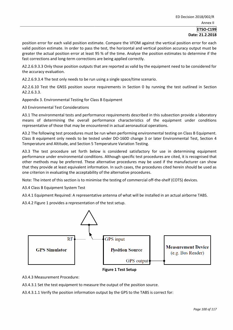
ED Decision 2018/002/R
Annex II
ETSO-C199
Date: 21.2.2018
Page 100 of 117
position error for each valid position estimate. Compare the VFOM against the vertical position error for each valid position estimate. In order to pass the test, the horizontal and vertical position accuracy output must be greater the actual position error at least 95 % of the time. Analyse the position estimates to determine if the fast corrections and long-term corrections are being applied correctly.
A2.2.6.9.3.3 Only those position outputs that are reported as valid by the equipment need to be considered for the accuracy evaluation.
A2.2.6.9.3.4 The test only needs to be run using a single space/time scenario.
A2.2.6.10 Test the GNSS position source requirements in Section 0 by running the test outlined in Section A2.2.6.3.3.
Appendix 3. Environmental Testing for Class B Equipment
A3 Environmental Test Considerations
A3.1 The environmental tests and performance requirements described in this subsection provide a laboratory means of determining the overall performance characteristics of the equipment under conditions representative of those that may be encountered in actual aeronautical operations.
A3.2 The following test procedures must be run when performing environmental testing on Class B Equipment. Class B equipment only needs to be tested under DO-160D change 3 or later Environmental Test, Section 4 Temperature and Altitude, and Section 5 Temperature Variation Testing.
A3.3 The test procedure set forth below is considered satisfactory for use in determining equipment performance under environmental conditions. Although specific test procedures are cited, it is recognised that other methods may be preferred. These alternative procedures may be used if the manufacturer can show that they provide at least equivalent information. In such cases, the procedures cited herein should be used as one criterion in evaluating the acceptability of the alternative procedures.
Note: The intent of this section is to minimise the testing of commercial off-the-shelf (COTS) devices.
A3.4 Class B Equipment System Test
A3.4.1 Equipment Required: A representative antenna of what will be installed in an actual airborne TABS.
A3.4.2 Figure 1 provides a representation of the test setup.
Figure 1 Test Setup
A3.4.3 Measurement Procedure:
A3.4.3.1 Set the test equipment to measure the output of the position source.
A3.4.3.1.1 Verify the position information output by the GPS to the TABS is correct for:

ED Decision 2018/002/R
Annex II
ETSO-C199
Date: 21.2.2018
Page 101 of 117
A3.4.3.1.1.1 The latitude and longitude of the surveyed location when connecting the device to a live (e.g. rooftop) antenna, or;
A3.4.3.1.1.2 The output by the GPS simulator for the scenario outlined in Section A2.2.6.3.3
A3.4.3.1.2 Using the test setup in A3.4.2, monitor the sensor provided HFOM, or HFOM derived from the sensor provided HDOP per paragraph A1.2.5.8. This output SHALL be compared against the horizontal position error for each valid position estimate. In order to pass the test, the horizontal position accuracy output must be greater than the actual position error for at least 95 % of the samples. The horizontal position error SHALL not exceed 0.5 NM at any time during the test.