euler’s theorem - geometer.orggeometer.org/mathcircles/euler.pdf · euler’s theorem tom davis...
TRANSCRIPT
Euler’s TheoremTom Davis
[email protected]://www.geometer.org/mathcircles
July 14, 2009
Abstract
Euler’s theorem is a nice result that is easy to investigate with simple models from Euclidean ge-ometry, although it is really a topological theorem. One of the advantages of studying it as presentedhere is that it provides the student many exercises in mentalvisualization and counting.
1 The Cube
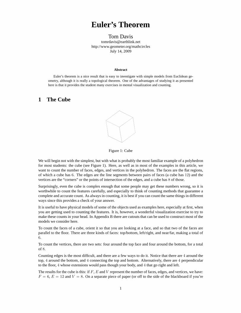
Figure 1: Cube
We will begin not with the simplest, but with what is probablythe most familiar example of a polyhedronfor most students: the cube (see Figure 1). Here, as well as inmost of the examples in this article, wewant to count the number of faces, edges, and vertices in the polyhedron. The faces are the flat regions,of which a cube has6. The edges are the line segments between pairs of faces (a cube has12) and thevertices are the “corners” or the points of intersection of the edges, and a cube has8 of those.
Surprisingly, even the cube is complex enough that some people may get these numbers wrong, so it isworthwhile to count the features carefully, and especiallyto think of counting methods that guarantee acomplete and accurate count. As always in counting, it is best if you can count the same things in differentways since this provides a check of your answer.
It is useful to have physical models of some of the objects used as examples here, especially at first, whenyou are getting used to counting the features. It is, however, a wonderful visualization exercise to try tomake these counts in your head. In Appendix B there are cutouts that can be used to construct most of themodels we consider here.
To count the faces of a cube, orient it so that you are looking at a face, and so that two of the faces areparallel to the floor. There are three kinds of faces: top/bottom, left/right, and near/far, making a total of6.
To count the vertices, there are two sets: four around the topface and four around the bottom, for a totalof 8.
Counting edges is the most difficult, and there are a few ways to do it. Notice that there are4 around thetop, 4 around the bottom, and4 connecting the top and bottom. Alternatively, there are4 perpendicularto the floor,4 whose extensions would pass though your body, and4 that go right and left.
The results for the cube is this: ifF , E andV represent the number of faces, edges, and vertices, we have:F = 6, E = 12 andV = 8. On a separate piece of paper (or off to the side of the blackboard if you’re
1
presenting this to a class), begin to make a table that looks like this with blank space available for a fewadditional entries. Leave space for one additional column on the right:
Object Faces (F ) Edges (E) Vertices (V )
Cube 6 12 8
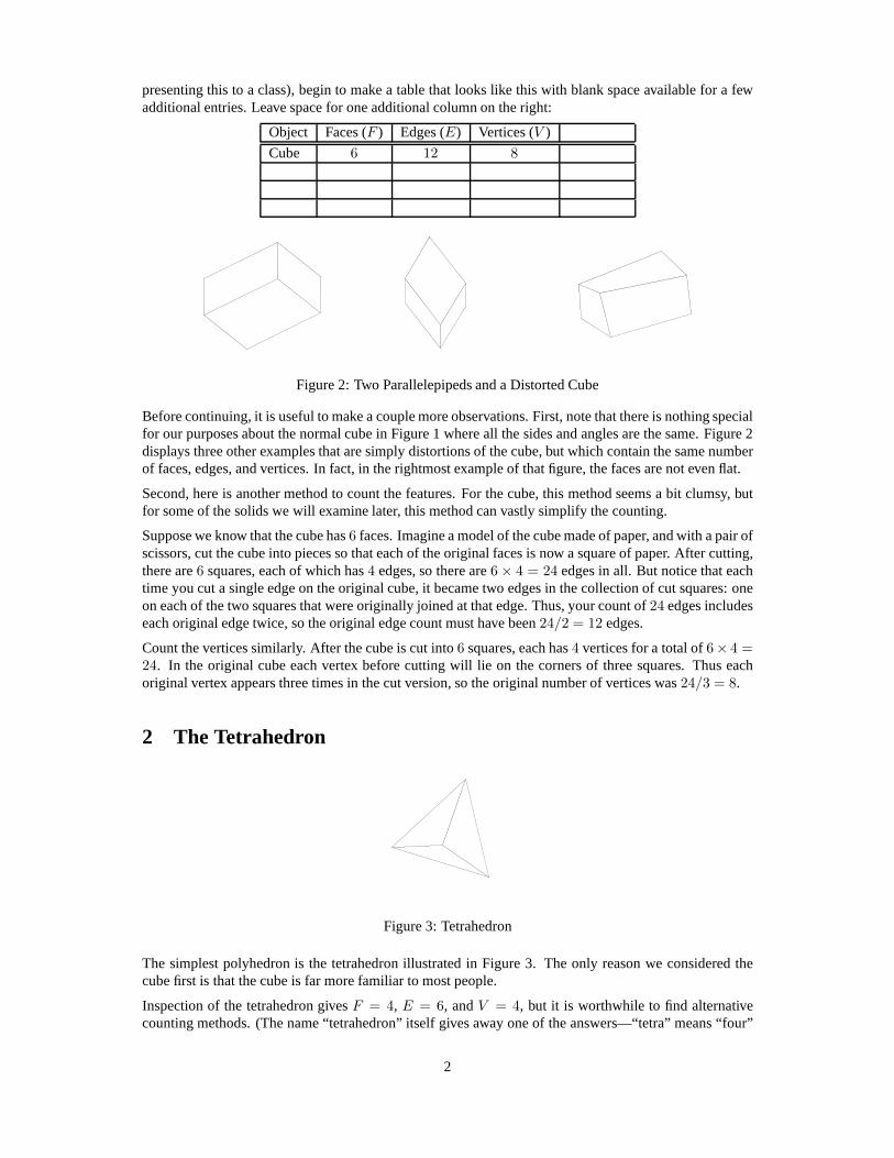
Figure 2: Two Parallelepipeds and a Distorted Cube
Before continuing, it is useful to make a couple more observations. First, note that there is nothing specialfor our purposes about the normal cube in Figure 1 where all the sides and angles are the same. Figure 2displays three other examples that are simply distortions of the cube, but which contain the same numberof faces, edges, and vertices. In fact, in the rightmost example of that figure, the faces are not even flat.
Second, here is another method to count the features. For thecube, this method seems a bit clumsy, butfor some of the solids we will examine later, this method can vastly simplify the counting.
Suppose we know that the cube has6 faces. Imagine a model of the cube made of paper, and with a pair ofscissors, cut the cube into pieces so that each of the original faces is now a square of paper. After cutting,there are6 squares, each of which has4 edges, so there are6 × 4 = 24 edges in all. But notice that eachtime you cut a single edge on the original cube, it became two edges in the collection of cut squares: oneon each of the two squares that were originally joined at thatedge. Thus, your count of24 edges includeseach original edge twice, so the original edge count must have been24/2 = 12 edges.
Count the vertices similarly. After the cube is cut into6 squares, each has4 vertices for a total of6× 4 =24. In the original cube each vertex before cutting will lie on the corners of three squares. Thus eachoriginal vertex appears three times in the cut version, so the original number of vertices was24/3 = 8.
2 The Tetrahedron
Figure 3: Tetrahedron
The simplest polyhedron is the tetrahedron illustrated in Figure 3. The only reason we considered thecube first is that the cube is far more familiar to most people.
Inspection of the tetrahedron givesF = 4, E = 6, andV = 4, but it is worthwhile to find alternativecounting methods. (The name “tetrahedron” itself gives away one of the answers—“tetra” means “four”
2
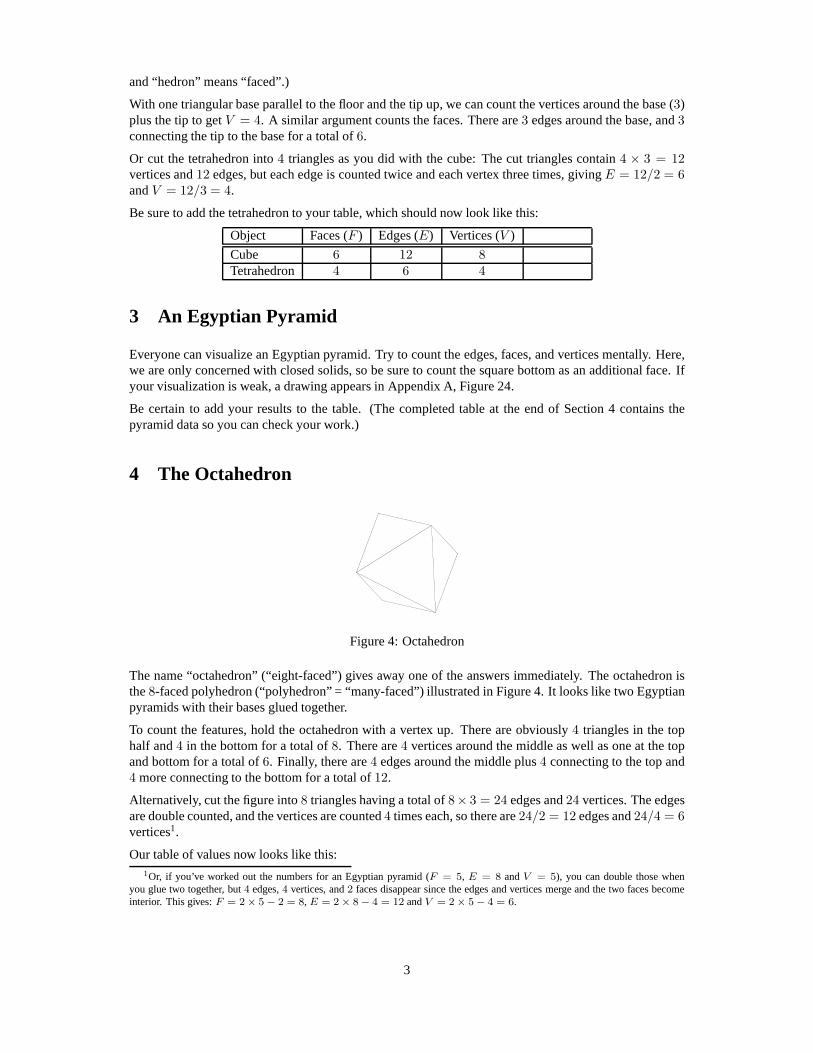
and “hedron” means “faced”.)
With one triangular base parallel to the floor and the tip up, we can count the vertices around the base (3)plus the tip to getV = 4. A similar argument counts the faces. There are3 edges around the base, and3connecting the tip to the base for a total of6.
Or cut the tetrahedron into4 triangles as you did with the cube: The cut triangles contain4 × 3 = 12vertices and12 edges, but each edge is counted twice and each vertex three times, givingE = 12/2 = 6andV = 12/3 = 4.
Be sure to add the tetrahedron to your table, which should nowlook like this:
Object Faces (F ) Edges (E) Vertices (V )
Cube 6 12 8Tetrahedron 4 6 4
3 An Egyptian Pyramid
Everyone can visualize an Egyptian pyramid. Try to count theedges, faces, and vertices mentally. Here,we are only concerned with closed solids, so be sure to count the square bottom as an additional face. Ifyour visualization is weak, a drawing appears in Appendix A,Figure 24.
Be certain to add your results to the table. (The completed table at the end of Section 4 contains thepyramid data so you can check your work.)
4 The Octahedron
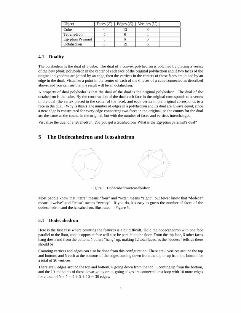
Figure 4: Octahedron
The name “octahedron” (“eight-faced”) gives away one of theanswers immediately. The octahedron isthe8-faced polyhedron (“polyhedron” = “many-faced”) illustrated in Figure 4. It looks like two Egyptianpyramids with their bases glued together.
To count the features, hold the octahedron with a vertex up. There are obviously4 triangles in the tophalf and4 in the bottom for a total of8. There are4 vertices around the middle as well as one at the topand bottom for a total of6. Finally, there are4 edges around the middle plus4 connecting to the top and4 more connecting to the bottom for a total of12.
Alternatively, cut the figure into8 triangles having a total of8× 3 = 24 edges and24 vertices. The edgesare double counted, and the vertices are counted4 times each, so there are24/2 = 12 edges and24/4 = 6vertices1.
Our table of values now looks like this:1Or, if you’ve worked out the numbers for an Egyptian pyramid (F = 5, E = 8 andV = 5), you can double those when
you glue two together, but4 edges,4 vertices, and2 faces disappear since the edges and vertices merge and the two faces becomeinterior. This gives:F = 2 × 5 − 2 = 8, E = 2 × 8 − 4 = 12 andV = 2 × 5 − 4 = 6.
3
Object Faces (F ) Edges (E) Vertices (V )
Cube 6 12 8Tetrahedron 4 6 4Egyptian Pyramid 5 8 5Octahedron 8 12 6
4.1 Duality
The octahedron is the dual of a cube. The dual of a convex polyhedron is obtained by placing a vertexof the new (dual) polyhedron in the center of each face of the original polyhedron and if two faces of theoriginal polyhedron are joined by an edge, then the verticesin the centers of those faces are joined by anedge in the dual. Visualize a point in the center of each of the6 faces of a cube connected as describedabove, and you can see that the result will be an octahedron.
A property of dual polyhedra is that the dual of the dual is theoriginal polyhedron. The dual of theoctahedron is the cube. By the construction of the dual each face in the original corresponds to a vertexin the dual (the vertex placed in the center of the face), and each vertex in the original corresponds to aface in the dual. (Why is this?) The number of edges in a polyhedron and its dual are always equal, sincea new edge is constructed for every edge connecting two facesin the original, so the counts for the dualare the same as the counts in the original, but with the numberof faces and vertices interchanged.
Visualize the dual of a tetrahedron. Did you get a tetrahedron? What is the Egyptian pyramid’s dual?
5 The Dodecahedron and Icosahedron
Figure 5: Dodecahedron/Icosahedron
Most people know that “tetra” means “four” and “octa” means “eight”, but fewer know that “dodeca”means “twelve” and “icosa” means “twenty”. If you do, it’s easy to guess the number of faces of thedodecahedron and the icosahedron, illustrated in Figure 5.
5.1 Dodecahedron
Here is the first case where counting the features is a bit difficult. Hold the dodecahedron with one faceparallel to the floor, and its opposite face will also be parallel to the floor. From the top face,5 other faceshang down and from the bottom,5 others “hang” up, making12 total faces, as the “dodeca” tells us thereshould be.
Counting vertices and edges can also be done from this configuration. There are5 vertices around the topand bottom, and5 each at the bottoms of the edges coming down from the top or up from the bottom fora total of20 vertices.
There are5 edges around the top and bottom,5 going down from the top,5 coming up from the bottom,and the10 endpoints of those down-going or up-going edges are connected in a loop with10 more edgesfor a total of5 + 5 + 5 + 5 + 10 = 30 edges.
4
The analysis “by scissors” is easier: Cut the figure into12 pentagons and you will have12×5 = 60 edgesand60 vertices. After cutting, the edges in the original are each counted twice and the vertices3 times,giving 60/2 = 30 edges and60/3 = 20 vertices.
Find other ways to count the faces, edges, and vertices of thedodecahedron.
5.2 Icosahedron
If you notice that the icosahedron is the dual of the dodecahedron, you getF = 20, E = 30 andV = 12.(Remember that we simply need to reverse the vertex and face counts in the dual.)
To do the scissors analysis, you first need to count the faces.Orient the icosahedron with one vertex upand its opposite down. There are5 faces touching the top and bottom vertices, as well as a ring of 10around the middle (or visualize one set of5 pointed “teeth” going down and another5 pointing up). Thusthere are20 total faces.
After cutting up the icosahedron with scissors, there are20×3 = 60 vertices and60 edges in the resultingtriangles, where each edge is double counted and each vertexis counted5 times. Thus there are60/2 = 30edges and60/5 = 12 vertices.
Try to count the number of vertices and edges directly.
In any case, if we add this data to our table, we obtain:
Object Faces (F ) Edges (E) Vertices (V )
Cube 6 12 8Tetrahedron 4 6 4Egyptian Pyramid 5 8 5Octahedron 8 12 6Dodecahedron 12 30 20Octahedron 20 30 12
Before reading on, take a look at all the data in this table andsee if you can find any numerical relation-ships among the numbers in each row.
6 Euler’s Theorem
There is enough numerical information in the table at the endof the previous section to find an interest-ing relationship among the numbersF , E andV . If you have not yet done so, please try to find thatrelationship yourself. (Hint: it is a linear relationship.)
Another hint is this: Because every one of our figures has a dual figure, the values ofF andV must enterthe relationship in the same way. In other words, any equation you obtain connecting the values ofF , EandV must remain the same ifF andV are interchanged so an equation likeF + 3V − 5E = 11 cannothold since interchangingF andV would giveV + 3F − 5E = 11.
With these hints and a little playing around, you should obtain the equation known as Euler’s theorem:
F − E + V = 2. (1)
Obviously we do not yet have a proof (or even a complete statement of the theorem—are there anyconditions the polyhedron must satisfy to guarantee the truth of the theorem?) We simply have countedthe number of faces, edges, and vertices of 6 polyhedra and noticed that the relationship displayed inEquation 1 holds for all of them.
Although the scientific method can never prove anything, it can certainly be applied to mathematics toincrease our confidence in the truth of a proposed theorem. Now that we think we have a formula relatingF , E, andV , let us verify that it holds in at least a few other cases.
5
6.1 Cylinders (or Prisms)
Figure 6: Pentagonal and Octagonal Cylinders
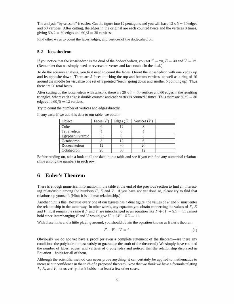
Figure 6 illustrates both a pentagonal and an octagonal cylinder. They are constructed by “extruding” abase that is either a pentagon or an octagon to make a solid.
The features of both are easy to count. For the pentagonal cylinder, there are5 faces around the outsideand2 on the top and bottom for a total of7. There are5× 2 = 10 edges around the top and bottom and5more connecting the top and bottom for a total of15. Finally, there are5 vertices on both top and bottomfor a total of10. ThusF = 7, E = 15 andV = 10. F − E + V = 7 − 15 + 10 = 2, so our proposedtheorem still seems to hold.
Similar reasoning for the octagonal cylinder givesF = 10, E = 24 andV = 16. F − E + V =10 − 24 + 16 = 2, giving one more data point.
Why not add an infinite number of data points? Let’s work out the numbers for a cylinder withn sides.The reasoning is identical: There aren + 2 faces,3n edges, and2n vertices.F − E + V = (n + 2) −3n + 2n = 3n + 2 − 3n = 2.
What is the dual of ann-sided cylinder?
6.2 General Pyramids (or Cones)
Figure 7: Generalized Pyramids
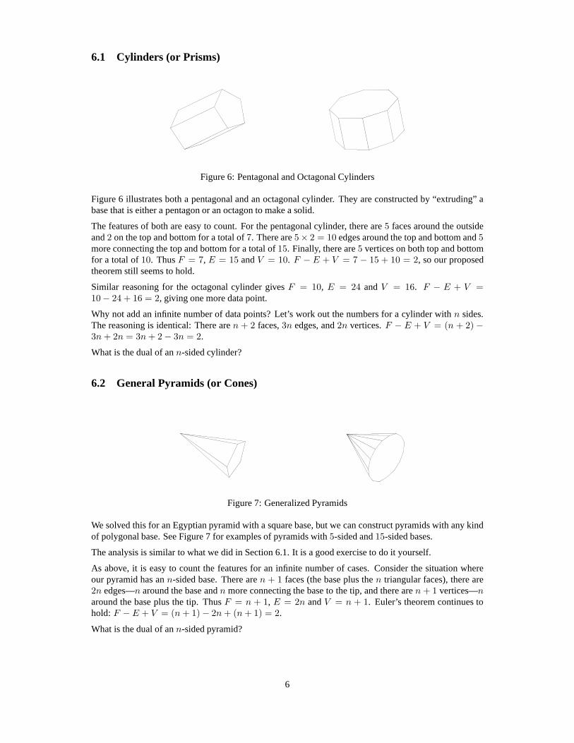
We solved this for an Egyptian pyramid with a square base, butwe can construct pyramids with any kindof polygonal base. See Figure 7 for examples of pyramids with5-sided and15-sided bases.
The analysis is similar to what we did in Section 6.1. It is a good exercise to do it yourself.
As above, it is easy to count the features for an infinite number of cases. Consider the situation whereour pyramid has ann-sided base. There aren + 1 faces (the base plus then triangular faces), there are2n edges—n around the base andn more connecting the base to the tip, and there aren + 1 vertices—naround the base plus the tip. ThusF = n + 1, E = 2n andV = n + 1. Euler’s theorem continues tohold: F − E + V = (n + 1) − 2n + (n + 1) = 2.
What is the dual of ann-sided pyramid?
6
7 The Truncated Icosahedron
Figure 8: Truncated Icosahedron (or Soccer Ball)
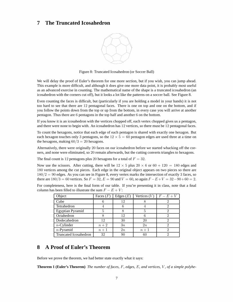
We will delay the proof of Euler’s theorem for one more section, but if you wish, you can jump ahead.This example is more difficult, and although it does give one more data point, it is probably most usefulas an advanced exercise in counting. The mathematical name of the shape is a truncated icosahedron (anicosahedron with the corners cut off), but it looks a lot likethe patterns on a soccer ball. See Figure 8.
Even counting the faces is difficult, but (particularly if you are holding a model in your hands) it is nottoo hard to see that there are12 pentagonal faces. There is one on top and one on the bottom, and ifyou follow the points down from the top or up from the bottom, in every case you will arrive at anotherpentagon. Thus there are6 pentagons in the top half and another6 on the bottom.
If you know it is an icosahedron with the vertices chopped off, each vertex chopped gives us a pentagon,and there were none to begin with. An icosahedron has12 vertices, so there must be12 pentagonal faces.
To count the hexagons, notice that each edge of each pentagonis shared with exactly one hexagon. Buteach hexagon touches only3 pentagons, so the12 × 5 = 60 pentagon edges are used three at a time onthe hexagons, making60/3 = 20 hexagons.
Alternatively, there were originally20 faces on our icosahedron before we started whacking off the cor-ners, and none were eliminated, so20 remain afterwards, but the cutting converts triangles to hexagons.
The final count is12 pentagons plus20 hexagons for a total ofF = 32.
Now use the scissors. After cutting, there will be12 × 5 plus 20 × 6 or 60 + 120 = 180 edges and180 vertices among the cut pieces. Each edge in the original object appears on two pieces so there are180/2 = 90 edges. As you can see in Figure 8, every vertex marks the intersection of exactly3 faces, sothere are180/3 = 60 vertices. SoF = 32, E = 90 andV = 60, so againF −E+V = 32−90+60 = 2.
For completeness, here is the final form of our table. If you’re presenting it in class, note that a finalcolumn has been filled to illustrate the sumF − E + V :
Object Faces (F ) Edges (E) Vertices (V ) F − E + V
Cube 6 12 8 2Tetrahedron 4 6 4 2Egyptian Pyramid 5 8 5 2Octahedron 8 12 6 2Dodecahedron 12 30 20 2n-Cylinder n + 2 3n 2n 2n-Pyramid n + 1 2n n + 1 2Truncated Icosahedron 32 90 60 2
8 A Proof of Euler’s Theorem
Before we prove the theorem, we had better state exactly whatit says:
Theorem 1 (Euler’s Theorem) The number of faces, F , edges, E, and vertices, V , of a simple polyhe-
7
dron are related by the formula F − E + V = 2.
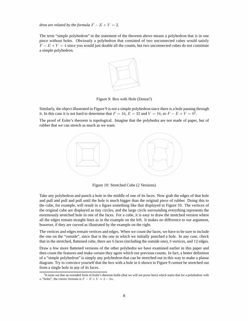
The term “simple polyhedron” in the statement of the theoremabove means a polyhedron that is in onepiece without holes. Obviously a polyhedron that consistedof two unconnected cubes would satisfyF − E + V = 4 since you would just double all the counts, but two unconnected cubes do not constitutea simple polyhedron.
Figure 9: Box with Hole (Donut?)
Similarly, the object illustrated in Figure 9 is not a simplepolyhedron since there is a hole passing throughit. In this case it is not hard to determine thatF = 16, E = 32 andV = 16, soF − E + V = 02.
The proof of Euler’s theorem is topological. Imagine that the polyhedra are not made of paper, but ofrubber that we can stretch as much as we want.
Figure 10: Stretched Cube (2 Versions)
Take any polyhedron and punch a hole in the middle of one of itsfaces. Now grab the edges of that holeand pull and pull and pull until the hole is much bigger than the original piece of rubber. Doing this tothe cube, for example, will result in a figure something like that displayed in Figure 10. The vertices ofthe original cube are displayed as tiny circles, and the large circle surrounding everything represents theenormously stretched hole in one of the faces. For a cube, it is easy to draw the stretched version whereall the edges remain straight lines as in the example on the left. It makes no difference to our argument,however, if they are curved as illustrated by the example on the right.
The vertices and edges remain vertices and edges. When we count the faces, we have to be sure to includethe one on the “outside”, since that is the one in which we initially punched a hole. In any case, checkthat in the stretched, flattened cube, there are6 faces (including the outside one),8 vertices, and12 edges.
Draw a few more flattened versions of the other polyhedra we have examined earlier in this paper andthen count the features and make certain they agree which ourprevious counts. In fact, a better definitionof a “simple polyhedron” is simply any polyhedron that can bestretched out in this way to make a planardiagram. Try to convince yourself that the box with a hole in it shown in Figure 9cannot be stretched outfrom a single hole in any of its faces.
2It turns out that an extended form of Euler’s theorem holds (that we will not prove here) which states that for a polyhedronwithn “holes”, the correct formula isF − E + V = 2 − 2n.
8
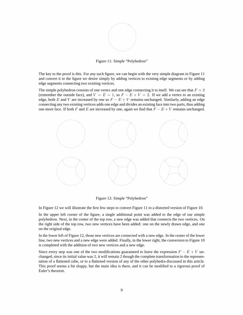
Figure 11: Simple “Polyhedron”
The key to the proof is this. Forany such figure, we can begin with the very simple diagram in Figure 11and convert it to the figure we desire simply by adding vertices to existing edge segments or by addingedge segments connecting two existing vertices.
The simple polyhedron consists of one vertex and one edge connecting it to itself. We can see thatF = 2(remember the outside face), andV = E = 1, soF − E + V = 2. If we add a vertex to an existingedge, bothE andV are increased by one soF − E + V remains unchanged. Similarly, adding an edgeconnecting any two existing vertices adds one edge and divides an existing face into two parts, thus addingone more face. If bothF andE are increased by one, again we find thatF − E + V remains unchanged.
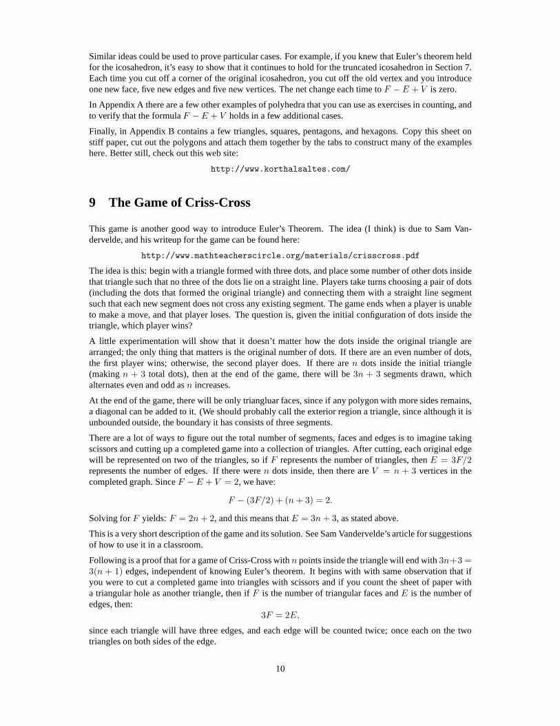
Figure 12: Simple “Polyhedron”
In Figure 12 we will illustrate the first few steps to convert Figure 11 to a distorted version of Figure 10.
In the upper left corner of the figure, a single additional point was added to the edge of our simplepolyhedron. Next, in the center of the top row, a new edge was added that connects the two vertices. Onthe right side of the top row, two new vertices have been added: one on the newly drawn edge, and oneon the original edge.
In the lower left of Figure 12, those new vertices are connected with a new edge. In the center of the lowerline, two new vertices and a new edge were added. Finally, in the lower right, the conversion to Figure 10is completed with the addition of two new vertices and a new edge.
Since every step was one of the two modifications guaranteed to leave the expressionF − E + V un-changed, since its initial value was2, it will remain2 though the complete transformation to the represen-tation of a flattened cube, or to a flattened version of any of the other polyhedra discussed in this article.This proof seems a bit sloppy, but the main idea is there, and it can be modified to a rigorous proof ofEuler’s theorem.
9
Similar ideas could be used to prove particular cases. For example, if you knew that Euler’s theorem heldfor the icosahedron, it’s easy to show that it continues to hold for the truncated icosahedron in Section 7.Each time you cut off a corner of the original icosahedron, you cut off the old vertex and you introduceone new face, five new edges and five new vertices. The net change each time toF − E + V is zero.
In Appendix A there are a few other examples of polyhedra thatyou can use as exercises in counting, andto verify that the formulaF − E + V holds in a few additional cases.
Finally, in Appendix B contains a few triangles, squares, pentagons, and hexagons. Copy this sheet onstiff paper, cut out the polygons and attach them together bythe tabs to construct many of the exampleshere. Better still, check out this web site:
http://www.korthalsaltes.com/
9 The Game of Criss-Cross
This game is another good way to introduce Euler’s Theorem. The idea (I think) is due to Sam Van-dervelde, and his writeup for the game can be found here:
http://www.mathteacherscircle.org/materials/crisscross.pdf
The idea is this: begin with a triangle formed with three dots, and place some number of other dots insidethat triangle such that no three of the dots lie on a straight line. Players take turns choosing a pair of dots(including the dots that formed the original triangle) and connecting them with a straight line segmentsuch that each new segment does not cross any existing segment. The game ends when a player is unableto make a move, and that player loses. The question is, given the initial configuration of dots inside thetriangle, which player wins?
A little experimentation will show that it doesn’t matter how the dots inside the original triangle arearranged; the only thing that matters is the original numberof dots. If there are an even number of dots,the first player wins; otherwise, the second player does. If there aren dots inside the initial triangle(makingn + 3 total dots), then at the end of the game, there will be3n + 3 segments drawn, whichalternates even and odd asn increases.
At the end of the game, there will be only triangluar faces, since if any polygon with more sides remains,a diagonal can be added to it. (We should probably call the exterior region a triangle, since although it isunbounded outside, the boundary it has consists of three segments.
There are a lot of ways to figure out the total number of segments, faces and edges is to imagine takingscissors and cutting up a completed game into a collection oftriangles. After cutting, each original edgewill be represented on two of the triangles, so ifF represents the number of triangles, thenE = 3F/2represents the number of edges. If there weren dots inside, then there areV = n + 3 vertices in thecompleted graph. SinceF − E + V = 2, we have:
F − (3F/2) + (n + 3) = 2.
Solving forF yields:F = 2n + 2, and this means thatE = 3n + 3, as stated above.
This is a very short description of the game and its solution.See Sam Vandervelde’s article for suggestionsof how to use it in a classroom.
Following is a proof that for a game of Criss-Cross withn points inside the triangle will end with3n+3 =3(n + 1) edges, independent of knowing Euler’s theorem. It begins with with same observation that ifyou were to cut a completed game into triangles with scissorsand if you count the sheet of paper witha triangular hole as another triangle, then ifF is the number of triangular faces andE is the number ofedges, then:
3F = 2E,
since each triangle will have three edges, and each edge willbe counted twice; once each on the twotriangles on both sides of the edge.
10
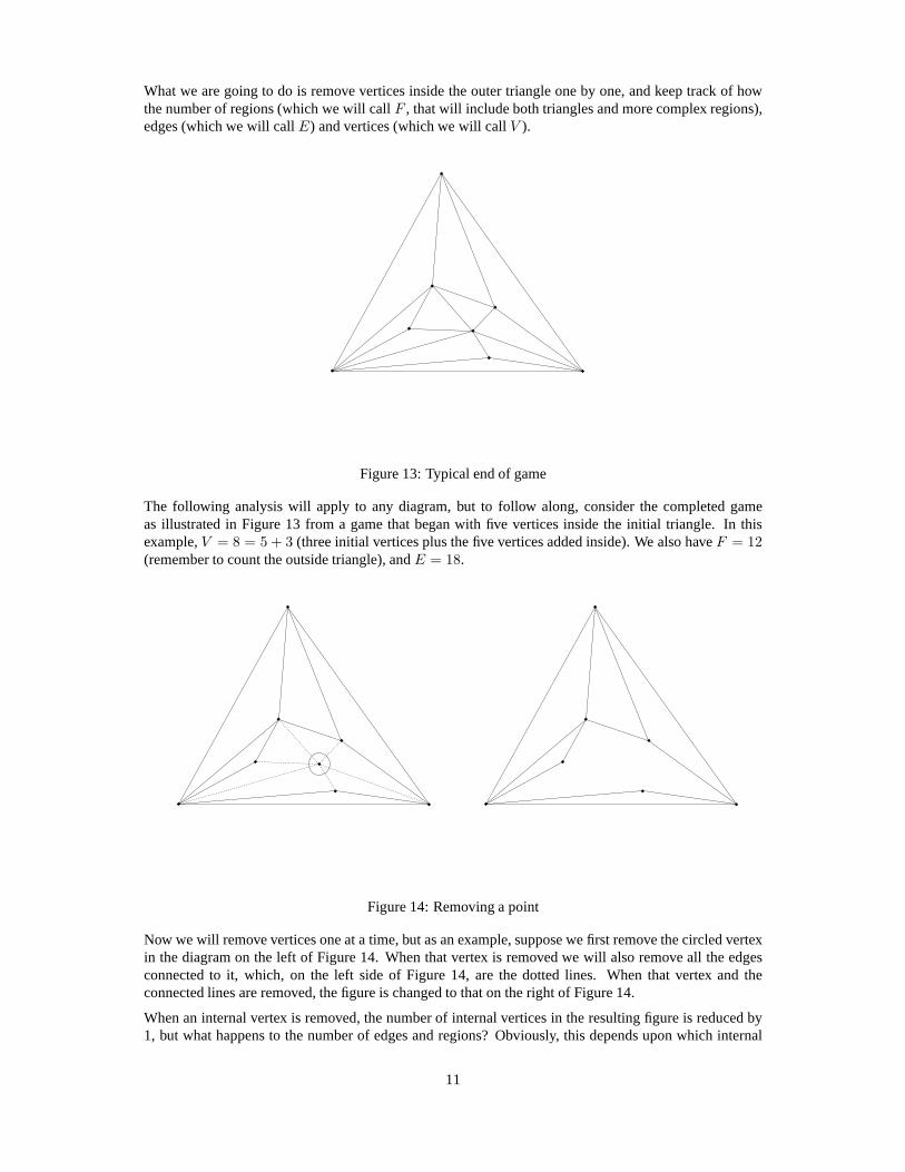
What we are going to do is remove vertices inside the outer triangle one by one, and keep track of howthe number of regions (which we will callF , that will include both triangles and more complex regions),edges (which we will callE) and vertices (which we will callV ).
Figure 13: Typical end of game
The following analysis will apply to any diagram, but to follow along, consider the completed gameas illustrated in Figure 13 from a game that began with five vertices inside the initial triangle. In thisexample,V = 8 = 5 + 3 (three initial vertices plus the five vertices added inside). We also haveF = 12(remember to count the outside triangle), andE = 18.
Figure 14: Removing a point
Now we will remove vertices one at a time, but as an example, suppose we first remove the circled vertexin the diagram on the left of Figure 14. When that vertex is removed we will also remove all the edgesconnected to it, which, on the left side of Figure 14, are the dotted lines. When that vertex and theconnected lines are removed, the figure is changed to that on the right of Figure 14.
When an internal vertex is removed, the number of internal vertices in the resulting figure is reduced by1, but what happens to the number of edges and regions? Obviously, this depends upon which internal
11
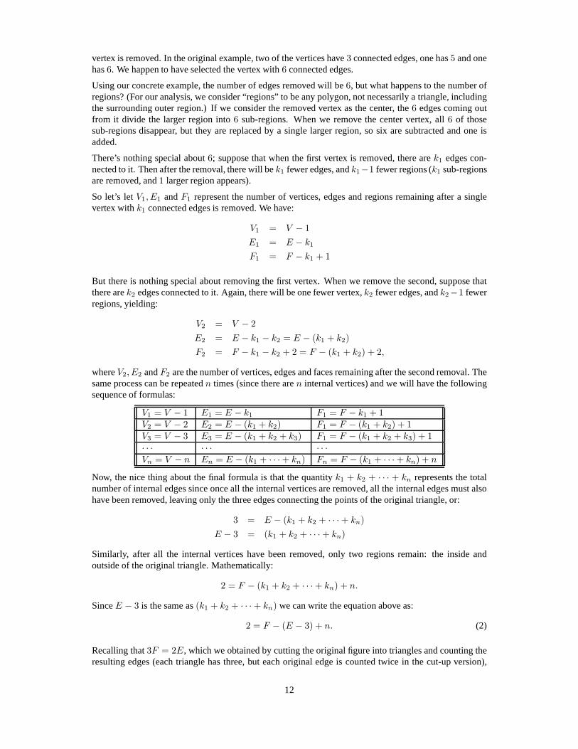
vertex is removed. In the original example, two of the vertices have3 connected edges, one has5 and onehas6. We happen to have selected the vertex with6 connected edges.
Using our concrete example, the number of edges removed willbe6, but what happens to the number ofregions? (For our analysis, we consider “regions” to be any polygon, not necessarily a triangle, includingthe surrounding outer region.) If we consider the removed vertex as the center, the6 edges coming outfrom it divide the larger region into6 sub-regions. When we remove the center vertex, all6 of thosesub-regions disappear, but they are replaced by a single larger region, so six are subtracted and one isadded.
There’s nothing special about6; suppose that when the first vertex is removed, there arek1 edges con-nected to it. Then after the removal, there will bek1 fewer edges, andk1−1 fewer regions (k1 sub-regionsare removed, and1 larger region appears).
So let’s letV1, E1 andF1 represent the number of vertices, edges and regions remaining after a singlevertex withk1 connected edges is removed. We have:
V1 = V − 1
E1 = E − k1
F1 = F − k1 + 1
But there is nothing special about removing the first vertex.When we remove the second, suppose thatthere arek2 edges connected to it. Again, there will be one fewer vertex,k2 fewer edges, andk2−1 fewerregions, yielding:
V2 = V − 2
E2 = E − k1 − k2 = E − (k1 + k2)
F2 = F − k1 − k2 + 2 = F − (k1 + k2) + 2,
whereV2, E2 andF2 are the number of vertices, edges and faces remaining after the second removal. Thesame process can be repeatedn times (since there aren internal vertices) and we will have the followingsequence of formulas:
V1 = V − 1 E1 = E − k1 F1 = F − k1 + 1V2 = V − 2 E2 = E − (k1 + k2) F1 = F − (k1 + k2) + 1V3 = V − 3 E3 = E − (k1 + k2 + k3) F1 = F − (k1 + k2 + k3) + 1· · · · · · · · ·Vn = V − n En = E − (k1 + · · · + kn) Fn = F − (k1 + · · · + kn) + n
Now, the nice thing about the final formula is that the quantity k1 + k2 + · · · + kn represents the totalnumber of internal edges since once all the internal vertices are removed, all the internal edges must alsohave been removed, leaving only the three edges connecting the points of the original triangle, or:
3 = E − (k1 + k2 + · · · + kn)
E − 3 = (k1 + k2 + · · · + kn)
Similarly, after all the internal vertices have been removed, only two regions remain: the inside andoutside of the original triangle. Mathematically:
2 = F − (k1 + k2 + · · · + kn) + n.
SinceE − 3 is the same as(k1 + k2 + · · · + kn) we can write the equation above as:
2 = F − (E − 3) + n. (2)
Recalling that3F = 2E, which we obtained by cutting the original figure into triangles and counting theresulting edges (each triangle has three, but each originaledge is counted twice in the cut-up version),
12
we’d like to combine this fact with Equation 2:
2 = F − (E − 3) + n
6 = 3F − 3(E − 3) + 3n
6 = 2E − 3E + 9 + 3n
E = 3 + 3n,
which is what we were trying to prove. Thus if the number of dots,n, is even, the number of edges willbe odd and vice-versa. So if the number of dots is odd, the firstperson wins, and if the number of dots iseven, the second person does.
10 Flattened polyhedra
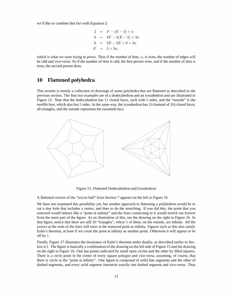
This section is mostly a collection of drawings of some polyhedra that are flattened as described in theprevious section. The first two examples are of a dodecahedron and an icosahedron and are illustrated inFigure 15. Note that the dodecahedron has11 closed faces, each with5 sides, and the “outside” is thetwelfth face, which also has5 sides. In the same way, the icosahedron has19 (instead of20) closed faces,all triangles, and the outside represents the twentieth face.
Figure 15: Flattened Dodecahedron and Icosahedron
A flattened version of the “soccer ball” from Section 7 appears on the left in Figure 16.
We have not examined this possibility yet, but another approach to flattening a polyhedron would be tocut a tiny hole that includes a vertex, and then to do the stretching. If you did this, the point that youremoved would behave like a “point at infinity” and the lines connecting to it would stretch out foreverfrom the main part of the figure. As an illustration of this, see the drawing on the right in Figure 16. Inthat figure, notice that there are still20 “triangles”, where5 of them, on the outside, are infinite. All thearrows at the ends of the lines will meet at the removed point at infinity. Figures such as this also satisfyEuler’s theorem, at least if we count the point at infinity as another point. Otherwise it will appear to beoff by 1.
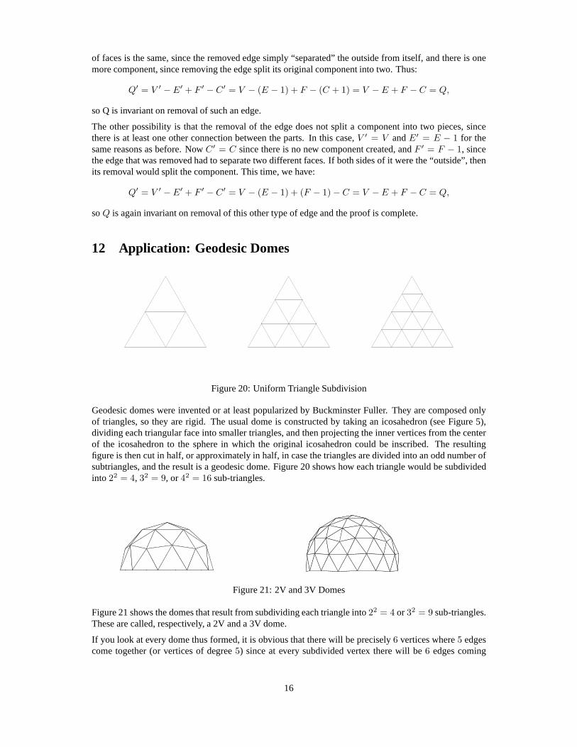
Finally, Figure 17 illustrates the invariance of Euler’s theorem under duality, as described earlier in Sec-tion 4.1. The figure is basically a combination of the drawingon the left side of Figure 15 and the drawingon the right in Figure 16. One has points indicated by small open circles and the other by filled squares.There is a circle point in the center of every square polygon and vice-versa, assuming, of course, thatthere is circle at the “point at infinity”. One figure is composed of solid line segments and the other ofdashed segments, and every solid segment intersects exactly one dashed segment and vice-versa. Thus
13
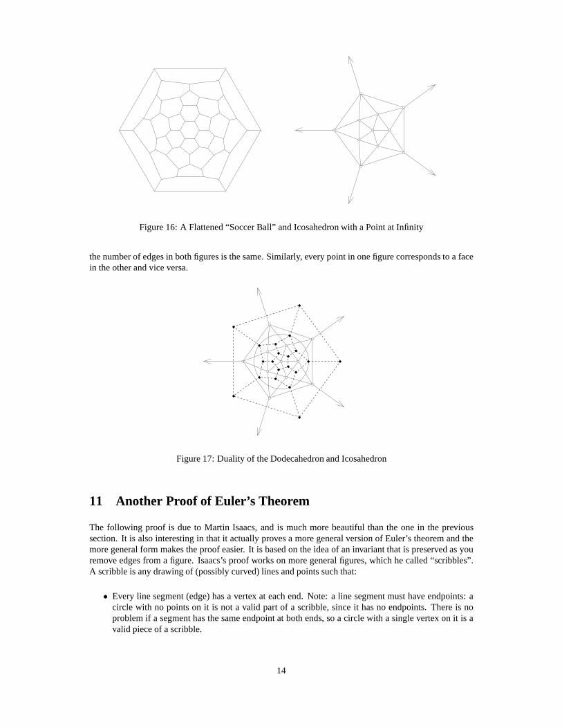
Figure 16: A Flattened “Soccer Ball” and Icosahedron with a Point at Infinity
the number of edges in both figures is the same. Similarly, every point in one figure corresponds to a facein the other and vice versa.
Figure 17: Duality of the Dodecahedron and Icosahedron
11 Another Proof of Euler’s Theorem
The following proof is due to Martin Isaacs, and is much more beautiful than the one in the previoussection. It is also interesting in that it actually proves a more general version of Euler’s theorem and themore general form makes the proof easier. It is based on the idea of an invariant that is preserved as youremove edges from a figure. Isaacs’s proof works on more general figures, which he called “scribbles”.A scribble is any drawing of (possibly curved) lines and points such that:
• Every line segment (edge) has a vertex at each end. Note: a line segment must have endpoints: acircle with no points on it is not a valid part of a scribble, since it has no endpoints. There is noproblem if a segment has the same endpoint at both ends, so a circle with a single vertex on it is avalid piece of a scribble.
14

Figure 18: A Simple Scribble
• Whenever two or more segments cross, there is a vertex at the crossing that separates all the crossingedges into pieces.
Figure 18 illustrates a scribble that contains8 vertices,10 edges, and4 faces, where the entire exterioris considered to be a single face. In this case,V = 8, E = 10 andF = 4, so we have the usual:F − E + V = 2, as it should.
Figure 19: A More Complex Scribble
Isaacs, however, added the possibility that a scribble could consist of multiple “components”, as illustratedin Figure 19. In that figure, there are four components, two ofwhich are single vertices. A “component”is a set of vertices connected by edges. Two components are different if there is no connection by edges ofthe vertices of one with the vertices of the other. In the example in Figure 19, we have:V = 12, E = 11,F = 4, andC = 4, where “C” is the number of components.
Components are simply disconnected pieces of a scribble. One component could completely surroundanother, so a circle with a point on it plus a single point inside the circle would be a scribble that consistsof two components (and two vertices, two faces, and one edge).
If you fool around with some examples (and at this point, it isa very good idea to do so), it appears to bethe case that:
V − E + F − C = 1,
which is identical to our original version of Euler’s formula in the case whereC = 1. It has the additionaladvantage of working for the empty scribble, since in that caseC = V = E = 0, butF = 1.
One other scribble that will turn out to be very interesting is the case where the scribble consists ofnothing except for, say,n vertices:V = n. In that case,F = 1, E = 0, C = V = n, and we have:V − E + F − C = n − 0 + 1 − n = 1, as it should.
Isaac’s proof works as follows: If we begin with a scribble with any degree of complexity (well, assumingthere are at most a finite number of vertices, edges and faces), then we can show that if any single edgeis removed from that scribble, the quantityQ = V − E + F − C is invariant; in other words, the valueof Q before and after the removal of the edge remains the same. So for any scribble that we begin with,although originally we don’t know the value ofQ, we show that successively simpler scribbles have thesame value ofQ, and when we eventually remove all the edges, we are left witha scribble that consistsonly of vertices, and we know that all such vertex-only scribbles satisfyV − E + F − C = 1.
When we remove a single edge from a scribble, there are two cases to consider. First, the removal of theedge might separate a single component into two. This will bethe case if there is no other edge connectingthe components. If the values for the original scribble areV , E, F andC, and the values for the newscribble with the edge removed areV ′, E′, F ′ andC′, it is easy to see that:V ′ = V , E′ = E − 1,F ′ = F andC′ = C + 1. There are no vertices added or removed, one edge is removed,the number
15
of faces is the same, since the removed edge simply “separated” the outside from itself, and there is onemore component, since removing the edge split its original component into two. Thus:
Q′ = V ′ − E′ + F ′ − C′ = V − (E − 1) + F − (C + 1) = V − E + F − C = Q,
so Q is invariant on removal of such an edge.
The other possibility is that the removal of the edge does notsplit a component into two pieces, sincethere is at least one other connection between the parts. In this case,V ′ = V andE′ = E − 1 for thesame reasons as before. NowC′ = C since there is no new component created, andF ′ = F − 1, sincethe edge that was removed had to separate two different faces. If both sides of it were the “outside”, thenits removal would split the component. This time, we have:
Q′ = V ′ − E′ + F ′ − C′ = V − (E − 1) + (F − 1) − C = V − E + F − C = Q,
soQ is again invariant on removal of this other type of edge and the proof is complete.
12 Application: Geodesic Domes
Figure 20: Uniform Triangle Subdivision
Geodesic domes were invented or at least popularized by Buckminster Fuller. They are composed onlyof triangles, so they are rigid. The usual dome is constructed by taking an icosahedron (see Figure 5),dividing each triangular face into smaller triangles, and then projecting the inner vertices from the centerof the icosahedron to the sphere in which the original icosahedron could be inscribed. The resultingfigure is then cut in half, or approximately in half, in case the triangles are divided into an odd number ofsubtriangles, and the result is a geodesic dome. Figure 20 shows how each triangle would be subdividedinto 22 = 4, 32 = 9, or 42 = 16 sub-triangles.
Figure 21: 2V and 3V Domes
Figure 21 shows the domes that result from subdividing each triangle into22 = 4 or 32 = 9 sub-triangles.These are called, respectively, a 2V and a 3V dome.
If you look at every dome thus formed, it is obvious that therewill be precisely6 vertices where5 edgescome together (or vertices of degree5) since at every subdivided vertex there will be6 edges coming
16
together and the original icosahedron had12 vertices of degree5. Since only half are used in a dome,there are12/2 = 6 vertices of degree5.
This is equivalent to saying that every sphere approximation, before cutting it in half, contains12 verticesof order5.
What is perhaps somewhat amazing is that it is possible to form an infinte number of sphere-like figuresfrom triangles such that every vertex has degree5 or 6, and not just by using the standard geodesic domedesign. Although the number of vertices of degree6 in such sphere-like objects can be almost anything,there are always exactly12 vertices of degree5. Using Euler’s theorem this is fairly easy to prove.
Let V5 andV6 represent the number of vertices in such a sphere-like object of degree5 and6, respectively.If we count all the outgoing edges, we obtain5V5 + 6V6, but this counts every edge twice, so the totalnumber of edges is half that:E = (5V5 + 6V6)/2. The number of triangles adjacent to the edges is thesame:5V5 + 6V6, but this triple-counts the triangles, since each will be counted adjacent to each of itsvertices. ThusF = (5V5 + 6V6)/3. The total number of vertices, of course, is justV = V5 + V6.
Euler’s theorem tells us that:
2 = V − E + F = V5 + V6 −5V5 + 6V6
2+
5V5 + 6V6
3.
A bit of algebra yields:
2 = V5 + V6 −15V5 + 18V6
6+
10V5 + 12V6
6
2 = V5 + V6 −5V5
6−
6V6
62 = V5/6
12 = V5.
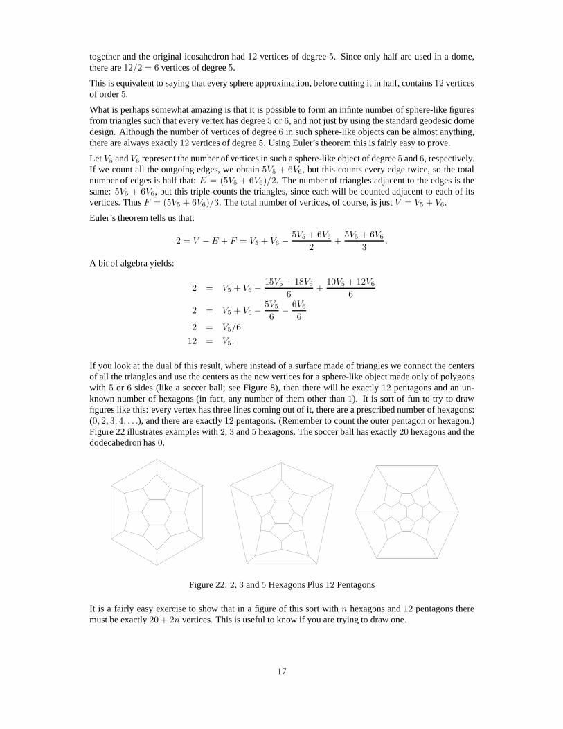
If you look at the dual of this result, where instead of a surface made of triangles we connect the centersof all the triangles and use the centers as the new vertices for a sphere-like object made only of polygonswith 5 or 6 sides (like a soccer ball; see Figure 8), then there will be exactly 12 pentagons and an un-known number of hexagons (in fact, any number of them other than1). It is sort of fun to try to drawfigures like this: every vertex has three lines coming out of it, there are a prescribed number of hexagons:(0, 2, 3, 4, . . .), and there are exactly12 pentagons. (Remember to count the outer pentagon or hexagon.)Figure 22 illustrates examples with2, 3 and5 hexagons. The soccer ball has exactly20 hexagons and thedodecahedron has0.
Figure 22:2, 3 and5 Hexagons Plus12 Pentagons
It is a fairly easy exercise to show that in a figure of this sortwith n hexagons and12 pentagons theremust be exactly20 + 2n vertices. This is useful to know if you are trying to draw one.
17
13 Application: The Six-Color Theorem
A very famous theorem in mathematics states that for any map that can be drawn on a plane (or on asphere), only four colors are required to paint the regions (which represent, say, countries) in such a waythat guarantees that countries sharing a boundary (not justa point) are of different colors. At the time ofthis writing, the only proof of this theorem is based on the output of a computer program that checkedthousands of cases to which the general problem had been reduced by mathematicians. So far there is notan easily-understood proof.
It is much easier to prove that five colors are sufficient, but what we will show here is that, as a relativelytrivial result of Euler’s theorem, that six colors are sufficient.
Map coloring can be reduced to a graph as follows: Place a vertex in the interior of every country anddraw an edge from that vertex to the vertices on the interiorsof all countries that share an edge by passingthat line through the shared edge. This is a dual of the country map, and is clearly planar. If colors can beassigned to each vertex such that no two vertices connected by an edge have the same color then we havea valid map coloring. What we will show here is that every planar map has a valid coloring using six orfewer colors.
The proof is not too difficult, and we will begin with an outline, followed by the details.
The proof is based on induction on the size of the graph. If thegraph has6 or fewer vertices, it is obviouslytrue. Assume that we know the theorem is true for any graph of size less thann, and for any graph of sizen > 6 we will use Euler’s theorem to show that the graph must have atleast one vertex of degree5 orless. If we remove that vertex, and all the edges coming from it, we will have a graph of sizen− 1 whichwe know is6-colorable by the induction hypothesis. If we add the vertexand edges we just removed, thenew vertex has only5 or fewer neighbors, so there will be a color available for it that will not conflictwith the other5 or fewer.
So all we really need to show is that any planar graph of size6 or larger has a vertex with5 or fewerneighbors. We will do this by using Euler’s theorem to show that for any planar connected graph with3or more vertices thatE ≤ 3V − 6. Then if we want to find the average degree of a vertex, we add allthe degrees and divide by the total number of vertices. Each edge has two vertices at its endpoints, so theaverage degreeD is given by:
D =(
∑
v∈V
deg(v))
/V = (2E/V ) ≤ (2(3V − 6))/V = 6 − 6/V.
This number is strictly smaller than6 so at least one vertex must have degree smaller than6.
All we need to do, then, is to prove that for any planar connected graph with 3 or more vertices, thatE ≤ 3V − 6.
If the graph has no cycles, thenE = V − 1 < V . SinceV ≥ 3 then2V − 6 ≥ 0. Add the inequalitiesE < V and0 ≤ 2V − 6 to obtainE < 3V − 6, so we are done in this case.
E1E1
E2E2
E3E3
E4E4F1F1
F2F2
Figure 23: Face and Edge Example
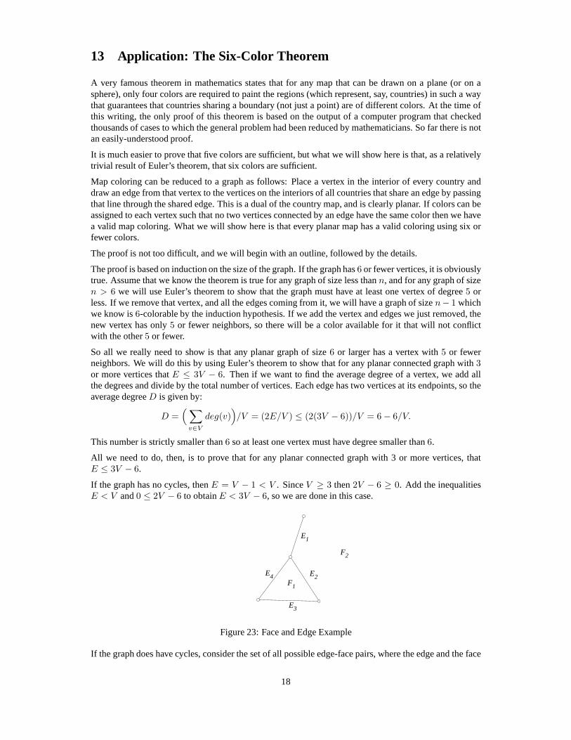
If the graph does have cycles, consider the set of all possible edge-face pairs, where the edge and the face
18
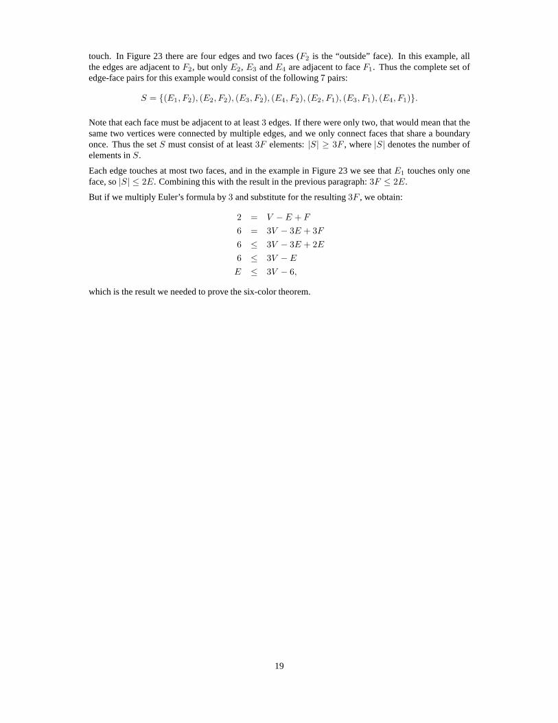
touch. In Figure 23 there are four edges and two faces (F2 is the “outside” face). In this example, allthe edges are adjacent toF2, but onlyE2, E3 andE4 are adjacent to faceF1. Thus the complete set ofedge-face pairs for this example would consist of the following 7 pairs:
S = {(E1, F2), (E2, F2), (E3, F2), (E4, F2), (E2, F1), (E3, F1), (E4, F1)}.
Note that each face must be adjacent to at least3 edges. If there were only two, that would mean that thesame two vertices were connected by multiple edges, and we only connect faces that share a boundaryonce. Thus the setS must consist of at least3F elements:|S| ≥ 3F , where|S| denotes the number ofelements inS.
Each edge touches at most two faces, and in the example in Figure 23 we see thatE1 touches only oneface, so|S| ≤ 2E. Combining this with the result in the previous paragraph:3F ≤ 2E.
But if we multiply Euler’s formula by3 and substitute for the resulting3F , we obtain:
2 = V − E + F
6 = 3V − 3E + 3F
6 ≤ 3V − 3E + 2E
6 ≤ 3V − E
E ≤ 3V − 6,
which is the result we needed to prove the six-color theorem.
19

A Additional Figures
Figure 24: Egyptian Pyramid, Cuboctahedron, Truncated Octahedron
Figure 25: Truncated Cube,8-Sided Bipyramid, Pentagonal Antiprism
Figure 26: Rhombic Dodecahedron, Rhombicuboctahedron, Truncated Tetrahedron
20
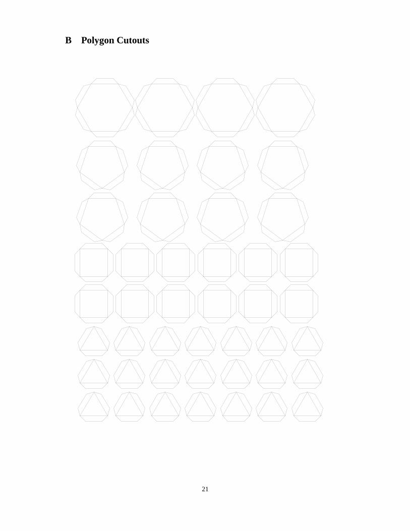
B Polygon Cutouts
21