euro iv - himalayan ls410 service manual...royal enfield euro iv - service manual ls 410 5 exploded...
TRANSCRIPT

EURO IV - HIMALAYAN LS410 SERVICE MANUAL
KS MOTORCYCLES - http://ksmotorcycles.com

ROYAL ENFIELD EURO IV - SERVICE MANUAL LS 410 1
“FIRST TIME RIGHT” is a very important element for enhancing Customer Satisfaction.
Royal Enfield is committed to upgradethe skills and knowledge of technicians so that they follow scientific repair
techniques to ensure “FIRST TIME RIGHT” practices and carry out repairs accurately so that customers will enjoy
trouble free performance at all times.
This manual will help in complete understanding of systematic procedures for dismantling, inspection, diagnosis and
reassembly of the new range of Royal Enfield, LS 410Single Cylinder, 4 Stroke, Overhead Cam, Air Cooled with Oil
cooler Engine, in a simple and scientific manner.
While this manual is updated with latest Information and Specifications, at the time of going to print, due to continuous
improvements being done to improve performance, some of the data, illustrations etc., in this manual may differ
from the actual parts fitted in the engine.
Please do feel free to write to us at [email protected], if you have any queries, clarification,
suggestions or feedback.
With warm regards
SERVICE HEAD QUARTERSRoyal Enfield, A Unit of Eicher Motors Limited,Thiruvottiyur High Road, Thiruvottiyur, Chennai - 600 019.Phone: 044 - 4223 0400, Fax: 044 - 4201 1719E-mail: [email protected]: www.royalenfield.com
“ © Copyright 2017 Royal Enfield (A Unit Eicher Motors Limited). All Rights Reserved. No part of this Service Manualshall be copied, distributed or otherwise dealt without the express permission in written from the Royal Enfield whoremains the sole owner of this manual .”
Part No: / Oct. ’17
PREFACE
ROYAL ENFIELD EURO IV - SERVICE MANUAL LS 410 01
KS MOTORCYCLES - http://ksmotorcycles.com

ROYAL ENFIELD EURO IV - SERVICE MANUAL LS 4102
CONTENTS
SL.NO. DESCRIPTION PG.NO. SL.NO. DESCRIPTION PG.NO.
1. Engine Views LH & RH ........................................ 3
2. Technical Specifications .................................... 4
3. Exploded Views ................................................. 5
4. Gear Operating Positions - LS 410 .................... 17
5. Oil Circulation ................................................... 19
6. Periodical Maintenance Chart - LS 410 ............ 20
7. Servicing / Overhauling .................................... 21
8. Components Dismantling Sequence .............. 22
9. Special Tools Usage List ................................... 23
10. Importance Notice Before Dismantling .......... 24Engine From Frame
11. Engine Dismantling Procedure Sequence ...... 25
12. Wear Limits - LS 410 ......................................... 66
13. Torque Values - LS 410 ..................................... 67
14. Precautions Before Engine Reassembly ......... 69
15. Trouble Shooting ........................................... 117
ROYAL ENFIELD EURO IV - SERVICE MANUAL LS 41002
KS MOTORCYCLES - http://ksmotorcycles.com

ROYAL ENFIELD EURO IV - SERVICE MANUAL LS 410 3
ENGINE VIEWS LH & RH
ROYAL ENFIELD EURO IV - SERVICE MANUAL LS 410 03
KS MOTORCYCLES - http://ksmotorcycles.com

ROYAL ENFIELD EURO IV - SERVICE MANUAL LS 4104
TECHNICAL SPECIFICATIONS
ENGINE& ENGINE SYSTEMSA. ENGINE LS 4101 Type Single Cylinder, 4 Stroke SOHC, Air cooled, Fuel Injection2 Bore 78 mm3 Stroke 86 mm4 Displacement 411 cc5 Compression ratio 9.5 : 16 Max Power @ RPM 24.5 BHP(18.02 Kw @ 6500 RPM7 Max Torque @ RPM 32 Nm @ 4000 RPM8 Idle RPM 1250 + 50 RPM @ EOT 80 deg9 Starting Electric Start10 Air filter element Paper element11 Lubrication Forced Lubrication, Wet Sump
12Engine oil tank capacity (1st Dry fill/ fill after 2.3 litrescomplete Engine Overhaul)Engine oil tank capacity(Routine Oil change/ 2.0 litresSubsequent refills)
13 Engine oil grade SAE 15W 50 API SL Grade JASO MA 214 Cooling Forced Air Cooled with Oil CoolerB. TRANSMISSION 1 Clutch Wet, Multiplate2 Primary drive Gear3 Primary ratio 2.312: 14 Gear box 5 Speed Constant Mesh
5
Gear Ratios 1st Gear 2.916:1 2nd Gear 1.833:1 3rd Gear 1.428:1 4th Gear 1.173:1 5th Gear 1:000:16 Secondary drive 5/8” Chain & Sprocket7 Secondary ratio 2.533:1C. FUEL1 Fuel PetrolD. IGNITION Digital Spark Ignition - TCI System1 Ignition Advance / Ignition System 5 – 30O / Electronic Ignition, ECU/Variable2 Spark plug Bosch - UR5CC3 Spark plug gap 0.7 to 0.8 mmE. ELECTRICALS1 System 12V - DC2 Generation Alternator3 Alternator Output 170W @ 1500 RPM
ROYAL ENFIELD SERVICE MANUAL LS 41004 ROYAL ENFIELD EURO IV - SERVICE MANUAL LS 41004
KS MOTORCYCLES - http://ksmotorcycles.com

ROYAL ENFIELD EURO IV - SERVICE MANUAL LS 410 5
EXPLODED VIEWS
CYLINDER HEAD COVER ASSEMBLY
1 Cover - Tappet Inlet
2 Hex Flange Bolt-M6 X 21
3 ‘O’ Ring - Camshaft Hole
4 Plug - Camshaft Hole
5 Hex Flange Bolt - M6 X 16
6 Hex Flange Bolt - M6 X 55
7 Hex Flange Bolt - M6 X 60
8 Gasket Washer – 6.2 X 14 X 1
9 Cover - Tappet Exhaust
S. NO. DESCRIPTION
10 O’ Ring - Tappet
11 Hex Flange Bolt - M6 X 40
12 Nut - Tappet Adjusting
13 Screws Tappet Adjusting
14 Arm comp valve Rocker
15 Shaft Valve Rocker Arm
16 Copper Washer
17 Plug - Rocker Shaft
18 Hex Flange Bolt - M6 X 45
S. NO. DESCRIPTION
2
1
10
2
18
1213
14
15
16
17
17
16
15
2
1011
2
8
777
6
6
6
5
43
14
13
12
ROYAL ENFIELD SERVICE MANUAL LS 410 05
9
ROYAL ENFIELD EURO IV - SERVICE MANUAL LS 410 05
KS MOTORCYCLES - http://ksmotorcycles.com

ROYAL ENFIELD EURO IV - SERVICE MANUAL LS 4106
CYLINDER HEAD ASSEMBLY
1 Cylinder Head & Cover Box Assembly2 Hollow Dowel (OD 9 X12), Cover cylinder3 Seat Valve Spring4 Seal Valve Stem - Intake5 Seal Valve Stem - Exhaust6 Spring Valve Inner7 Spring Valve Outer8 Retainer Valve Spring9 Cotter Valve10 Spark Plug11 Bolt Cylinder Head M10 X 17012 Washer Cyl Head Bolt
S. NO. DESCRIPTION S. NO. DESCRIPTION
13 Cover- Cam Center14 Hex Flange Bolt - M6 X 1615 Hex Flange Bolt - M6 X 3016 Valve Exhaust17 Valve Inlet18 Nut M8 X 1.2519 Stud Exhaust20 Damper Pad - Cylinder Head Front21 Damper Pad RH - Cylinder Head22 Damper Pad - Cylinder Head Back23 Damper Pad LH - Cylinder Head
1
1918
17 1615 14
356
7
8
912
12
11
11
2
20
21
22
23
13
10
8
9
7
64
3
ROYAL ENFIELD EURO IV - SERVICE MANUAL LS 41006
KS MOTORCYCLES - http://ksmotorcycles.com

ROYAL ENFIELD EURO IV - SERVICE MANUAL LS 410 7
CYLINDER BARREL & PISTON ASSEMBLY
1 Gasket - Cylinder Head MLS2 Hollow Dowel (OD 13X18) - Cylinder Barrel3 Hex Flange Nut – M6 X 1, Cylinder Barrel4 Gasket - Cylinder Barrel5 Pin Piston
S. NO. DESCRIPTION S. NO. DESCRIPTION
1
2
3
4
5
67
8
9
6
2
10
A1
6 Circlip - Piston Pin7 Ring – Piston 1st8 Ring – Piston 2nd9 Ring – Piston oil10 Damper Pads Cylinder barrel
ROYAL ENFIELD EURO IV - SERVICE MANUAL LS 410 07
KS MOTORCYCLES - http://ksmotorcycles.com

ROYAL ENFIELD EURO IV - SERVICE MANUAL LS 4108
CAM CHAIN ASSEMBLY
1 Pin, Control Arm Pivot
2 Pin Assy Decomp
3 Arm, Decompression Control
4 Spring, Control Arm
5 Cam Shaft Assy
6 Pin, Camshaft Sprocket
7 ‘C’ Ring, Camshaft
8 Lock Washer, Camshaft Sprocket
9 Bolt – M6 X 12, Camshaft Sprocket
S. NO. DESCRIPTION
10 Sprocket- cam shaft
11 Cam Chain
12 Guide pad
13 Tensioner Pad
14 Gasket - Chain Tensioner
15 Auto Chain Tensioner Assy
16 Hex. Socket Head. Cap Screw, M6 X 25
17 Bolt Stepped M6 X 14, Cam Chain Tensioner
18 Washer - 6 X 18 X 1, Cam chain Tensioner Bolt
S. NO. DESCRIPTION
21
7
610
8
9 11
12
13
14 15 16
1817
4
3
5
ROYAL ENFIELD EURO IV - SERVICE MANUAL LS 41008
KS MOTORCYCLES - http://ksmotorcycles.com

ROYAL ENFIELD EURO IV - SERVICE MANUAL LS 410 9
CRANK TRAIN
1 Crank Shaft with Balancer Shaft Assembly
2 Washer 10.5 X 28 X 2.5, Crank Balancer
3 Washer Belleville, Crank Balancer Lock
4 Hex Flange Bolt - M10 X 20
5 Sprocket – Oil pump Driven
6 Chain oil pump
7 Sprocket – Oil pump Drive
S. NO. DESCRIPTION
8 Nut- LH- M18, Oil Pump Drive Gear
9 Washer, Oil Pump sprocket Lock
10 Washer-22X4X1.5, Primary Drive GearThrust
S. NO. DESCRIPTION
5
89
6
710
43
2
1
ROYAL ENFIELD EURO IV - SERVICE MANUAL LS 410 09
KS MOTORCYCLES - http://ksmotorcycles.com

ROYAL ENFIELD EURO IV - SERVICE MANUAL LS 41010
8
7
6
3
A125
4
1
9
E-START SYSTEM
A1 Starter Clutch Assembly
1 Gear, Starter Idle No.2
2 Spacer - Idler Gear
3 Gear, Starter Idle No.1 (Double Gear)
4 Shaft Starter Idle Gear No.2
5 Shaft Starter Idle Gear No.1
S. NO. DESCRIPTION S. NO. DESCRIPTION
6 ‘O’ Ring Starter Motor
7 Starter Motor Assy
8 Hex Flange Bolt - M6 X 30
9 Hex Soc. Head Screw - M6 X 20
KS MOTORCYCLES - http://ksmotorcycles.com

ROYAL ENFIELD EURO IV - SERVICE MANUAL LS 410 11
8
7
6
3
A1
3
45
3
2
1
3
9
10
11
COVER LH
A1 Magneto Assembly
1 Cover LH
2 Hollow Dowel - OD13 X 18, Cover LH
3 Hex Flange Bolt M6 X 35
4 Copper Washer, Oil Check Plug
5 Plug, Oil Check– M14 X 12
6 Hex Socket Head Screw M5 X 30
S. NO. DESCRIPTION
7 Hex Socket Head Screw M5 X 15
8 Clamp Starter Wire
9 Hex Flange Bolt M6 X 55
10 O Ring
11 Cover Crankshaft Center
12 Hex Socket Head Screw M6 X 14
13 Gasket, Cover LH
S. NO. DESCRIPTION
13
12
KS MOTORCYCLES - http://ksmotorcycles.com

ROYAL ENFIELD EURO IV - SERVICE MANUAL LS 41012
A1 Magneto AssemblyA2 Starter Clutch Assembly1 Hex Flange Nut - M12 X 1.25P X 11(W), Magneto2 Key Woodruff3 Hex Soc. Head Screw - M6 X 204 Hex Flange Bolt-M6X16 Gear Position Switch5 Terminal Gear Position Switch6 Pin, Gear Position7 Spring, Gear Position Pin8 Oil Seal, Gear Shift Shaft9 Hex Flange Bolt - M6 X 20, Oil Strainer Cover10 Plug M14 X 12, Oil Drain11 Copper Washer Drain plug12 Cover, Strainer13 O-Ring, Oil Strainer Cover14 Strainer Comp. Engine Oil15 Hex Flange Bolt M8 X 12, Oil Gallery16 Gasket Washer - 8.2 X 16 X 1, Oil Gallery Bolt17 Hex Soc. Head Screw - M6 X 1218 Jet Comp, Starter Clutch Oil19 O-Ring - 4 X 1.2, Oil Jet
S. NO. DESCRIPTION S. NO. DESCRIPTION
20 Jet Comp, Piston Oil21 Bearing (#6204),Crank Balancer22 Bearing (#6203LU),COUNTER SHAFT,LH23 Stud M6 X 37, Cylinder Barrel24 Hollow Dowel - Od13 X 18, Crankcase Lh25 Bearing (#6305LU), Drive shaft LH26 Oil Seal, Drive Shaft27 O-Ring, Spacer Engine Sprocket28 Spacer, Engine Sprocket29 Sprocket Comp - Final Drive Engine 15T (#525)30 Tab Washer M20, Engine Sprocket Lock31 Nut M20, Engine Sprocket32 Retainer, Drive Shaft Oil Seal33 Bolt M6 X 10, Drive Shaft Oil Seal Retainer34 Sprocket Cover35 Hex Flange Bolt - M6 X 3536 Hex Flange Bolt - M8 X 10037 Hex Flange Bolt- M8 X 7038 Hex Flange Bolt – M6 X 6039 Hex Flange Bolt - M6 X 85
39
CRANKCASE LH
2224
2123
19
20
15 16
15 16 19 18 17 16 15
2414
1312 9 1110
6 978
54
2627 28
29
3031 32
33 35
34
A2
25
39383736
38
3
2
1A1
3738 393837
17
KS MOTORCYCLES - http://ksmotorcycles.com

ROYAL ENFIELD EURO IV - SERVICE MANUAL LS 410 13
1112
1110
8
9 8 65
3 4
3
32
2 1
24
22
23
1819
2021
13
1819
8 9
14
15
13
16 17
CRANKCASE RH
1 Circlip Oil Pump Shaft2 Washer 8 X 16 X 0.5 Oil pump sprocket3 Hex Flanged Bolt – M6 X 304 Pump Assy, Oil5 Gasket6 Stopper, Gear Shift Arm7 Bearing -#16005 , Gear Shift Drum RH8 Hex socket head screw - M6 X 129 Retainer, Counter Shaft Bearing10 Circlip 17 X 1, Kick Idle Gear.11 Washer - 17 X 28 X 1, Kick Idle Gear Thrust12 Spacer Drive Shaft
S. NO. DESCRIPTION S. NO. DESCRIPTION
13 Hollow Dowel (Od13X18), Cover-RH14 Bearing - 6304, Counter Shaft RH15 Bearing - 6203, Drive Shaft RH16 Bearing - 6306, Crankshaft RH17 Bearing - 6204,Crank Balancer18 Oil jet19 O-Ring - 4 X 1.2, Oil Jet20 Copper Washer Drain plug21 Plug oil check M1422 Sprocket – Oil pump Drive23 Chain oil pump24 Sprocket – Oil pump Driven
KS MOTORCYCLES - http://ksmotorcycles.com

ROYAL ENFIELD EURO IV - SERVICE MANUAL LS 41014
COVER RH
8
76
54 2
3
2
12
2411 23
22
21
20
11
19
113
9
2
1110
1213
18
1716
1415
1
9
11
1 Cover RH Assembly2 Hex Flanged Bolt M6 X 1 X 303 Hollow Dowel (OD13X18), Cover-RH4 Oil Filter5 Spring Oil Filter6 O Ring Oil Filter7 Cap Oil Filter8 Hex Flange Bolt - M6 X 709 Hex Flanged Bolt M6 X 1 X 2010 Bracket, Clutch Release11 Hex Flange Bolt - M6 X 3712 O Ring Oil Filler
S. NO. DESCRIPTION S. NO. DESCRIPTION
13 Plug Oil Filler14 Seal Clutch Release15 Washer Clutch Release16 Spring Clutch Release17 Hex flange bolt M6 X 718 Shaft Clutch19 Gasket Cover RH20 Hex Socket Head Screw M6 X 1221 Plate Retainer22 Oil Seal Crankshaft RH23 Jet, Crank Shaft RH24 Lens Oil Level Check
KS MOTORCYCLES - http://ksmotorcycles.com

ROYAL ENFIELD EURO IV - SERVICE MANUAL LS 410 15
911
12
13
14
1516
17
2
3
4
65
1
10
CLUTCH
1 Friction Plate
2 Plate Clutch
3 Wheel Clutch
4 Thrust Washer
5 Housing Assembly
6 Belleville Spring (Jadder spring)
7 Plain Washer (Jadder washer)
8 Hub Clutch With Ring
9 Compression Spring
10 Holder Clutch
S. NO. DESCRIPTION S. NO. DESCRIPTION
11 Hex Bolt M6
12 Washer, Clutch Sleeve Hub Lock
13 Nut M20 - Clutch Sleeve Hub
14 Bearing Cup
15 Bearing 17X35X10
16 Pin, Clutch Release
8
7
KS MOTORCYCLES - http://ksmotorcycles.com

ROYAL ENFIELD EURO IV - SERVICE MANUAL LS 41016
TRANSMISSION
1 Washer - 17 X 28 X 1, Drive Shaft thrust2 Bush, 1st Driven Gear3 Gear, 1st Driven4 Washer - 20 X 30 X 1, 1st Driven Gear thrust5 Gear, 5th Driven6 Circlip 25 X 1.2, 5th Drive Gear7 Washer, 3rd & 4th Driven Gear8 Bush, 3rd & 4th Driven Gear9 Gear, 4th Driven10 Washer, thrust Washer Lock11 Washer,3rd & 4th Driven Gear thrust12 Gear, 3rd Driven13 Wheel, Sliding Dog14 Bush, 2nd Driven Gear15 Gear, 2nd Driven16 Shaft Comp, Drive17 Gear, 2nd Driven18 Gear, 3rd & 4th Drive19 Washer - 25 X 34 X 1, 5th Drive Gear thrust20 Gear, 5th Drive21 Bush, 5th Drive Gear
S. NO. DESCRIPTION S. NO. DESCRIPTION
22 Shaft Comp, Counter23 Spacer primary drive24 Fork, Gear Shift No.125 Shaft, Gear Shift Fork26 Fork, Gear Shift No.227 Fork, Gear Shift No.328 Cam Comp, Gear Shift29 Star Index, Gear Shift Cam30 Stepped Bolt Hex Soc. Hd , Star Index31 Bolt Stepped, Gear Shift Cam Stopper32 Arm Stopper Comp, Gear Shift Cam33 Washer - 6 X 18 X 1, Tensioner Bolt34 Spring, Gear Shift Cam Stopper35 Circlip-14 X 1, Gear Shift Shaft36 Washer 14 X 25 X 0.8, Gear Shift Shaft Thrust37 Shim, Gear Shift Shaft38 Spring, Gear Shift Shaft Return39 Shaft Comp, Gear Shift40 Plate, Gear Shift Cam Drive41 Spring, Gear Shift Cam Drive Plate
3
56
4
7 8
910 11 8
127 6
13
6 13
15 16
35 37 4140
39 3835 37 36 35
3132
33 3430
292825
24
2322
21 2019
18 6 17 1
2627
61 2
KS MOTORCYCLES - http://ksmotorcycles.com

ROYAL ENFIELD EURO IV - SERVICE MANUAL LS 410 17
OIL COOLER
6
5
4
3
2
1
1 2
7
8
7
5
4
1 Copper Washer
2 Bolt - Union Crankcase
3 Pipe Comp Engine Oil No 1
4 Hexagonal Nut M6
S. NO. DESCRIPTION S. NO. DESCRIPTION
5 O Ring Oil Coole
6 Oil Cooler
7 Hex.Socket Head Cap Screw M6 X 25
8 Pipe Comp Engine Oil No 2
KS MOTORCYCLES - http://ksmotorcycles.com

ROYAL ENFIELD EURO IV - SERVICE MANUAL LS 41018
GEAR OPERATING POSITIONS - LS 410
1ST GEAR
2ND GEAR
Clutch
Drive Shaft Gears1st 5th 4th 3rd 2nd
Final DriveSprocket
Counter Shaft Gears
1st 5th 4th 3rd 2nd
Clutch
Drive Shaft Gears1st 5th 4th 3rd 2nd
Final DriveSprocket
Counter Shaft Gears
1st 5th 4th 3rd 2nd
Clutch
Drive Shaft Gears1st 5th 4th 3rd 2nd
Final DriveSprocket
Counter Shaft Gears
1st 5th 4th 3rd 2nd
3RD GEAR
KS MOTORCYCLES - http://ksmotorcycles.com

ROYAL ENFIELD EURO IV - SERVICE MANUAL LS 410 19
4TH GEAR
5TH GEAR
Clutch
Drive Shaft Gears1st 5th 4th 3rd 2nd
Final DriveSprocket
Counter Shaft Gears
1st 5th 4th 3rd 2nd
Clutch
Drive Shaft Gears1st 5th 4th 3rd 2nd
Final DriveSprocket
Counter Shaft Gears
1st 5th 4th 3rd 2nd
KS MOTORCYCLES - http://ksmotorcycles.com

ROYAL ENFIELD EURO IV - SERVICE MANUAL LS 41020
OIL CIRCULATION
ENGINE-OIL FLOW
LH VIEW RH VIEW
Oil Pump Oil FilterOil Strainer screen
Counter shaftMain shaft
Cam shaft
Oil Gallery
KS MOTORCYCLES - http://ksmotorcycles.com

ROYAL ENFIELD EURO IV - SERVICE MANUAL LS 410 21
The Periodical maintenance schedule detailed below is based upon average riding conditions and indicates theIntervals at which regular inspections, adjustments, replacements and lubrications must be carried out to help maintainyour Himalayan motorcycle meticulously
If in case the motorcycle is used frequently in very dusty environment / severe climatic conditions / Poor Roads /stagnant water etc., the maintenance will need to be done earlier as may be required.
Contact a nearest Royal Enfield Authorised Dealer / Service Center to carry out the periodical maintenance and forany expert advice.
PERIODICAL MAINTENANCE CHART - LS 410
A : A d j u s t C : C l e a n I : I n s p e c t L : L u b r i c a t e R : R e p l a c e
* Refer Service Manual.
# Check every time after vehicle is used for off road riding
For maintenance after 50,000 Kms. , please repeat same frequency specified above, in consultation with a RoyalEnfield Authorised Dealer / Service Center.
S.No. DESCRIPTION FREE SERVICE
Whichever is earlierPAID SERVICE
Whichever is earlierKms (x 1000) 0.5 5 10 15 20 25 30 35 40 45 50
Months 1.5 6 12 18 24 30 36 42 48 54 60
1 Engine Oil (Level check / Replace)R I R I R I R I R I R
Check level at every 1000 Kms or earlier as required
2 Oil Filter Element R R R R R R
3 Engine oil strainer on crankcase LH C C C C C C
4 Inlet / Exhaust Tappet setting I&A I&A I&A I&A I&A I&A I&A I&A I&A I&A I&A
5 Rubber hose, Inlet manifold * I I R I R I R I R I R
6 Oil cooler inlet & outlet pipes * I I I R I I R I I R I
7 Spark plug C&A C&A C&A R C&A C&A R C&A C&A R C&A
8 Accelerator Cable I I R I R I R I R I R
9 Clutch Plates R R R
10 Cam Chain / Chain Pads / Auto chain Tensioner I I I I I I I I I I I&R
11 Inlet / Exhaust valve seating (compression test) * I I
KS MOTORCYCLES - http://ksmotorcycles.com

ROYAL ENFIELD EURO IV - SERVICE MANUAL LS 41022
SERVICING / OVERHAULING POSSIBLEWITHOUT DISMANTLING ENGINE FROMFRAME Inlet & Exhaust Tappet adjustments
Auto Chain Tensioner, Cam shaft assembly, Camchain, pads
Cylinder Head assembly
Cylinder Barrel, Piston&Rings
Clutch assembly
Oil pump assembly
Gears operating mechanism/ gear shift shaft oil seals
Magneto Stator / Rotor Assembly
Starter Clutch Assembly
Starter Motor replacement
Gear position sensor switch ,
Final Drive sprocket.
SERVICING / OVERHAULING FORWHICH ENGINE HAS TO BE REMOVEDFROM FRAME Crankcases opening
Crank shaft / Balancer Shaft / Main Shaft / CounterShaft / Gears / Gear Operator forks / Gear SelectorDrum.
Crank case bearings.
KS MOTORCYCLES - http://ksmotorcycles.com

ROYAL ENFIELD EURO IV - SERVICE MANUAL LS 410 23
COMPONENTS DISMANTLING SEQUENCE
COMPONENTS DISMANTLING SEQUENCE TO REMOVE ENGINE FROM FRAME
Skid Plate on Frame bottom.(Himalayan models)
Engine oil (Drain when warm. Remove drain plug /oil strainer cover on crankcase LH & Oil filter on CoverRH)
Oil Cooler along with inlet & outlet pipes.
Fuel hose & Pulse Air valve connections
Battery connections
TPS/Magneto/Gear position/ Side stand switch:couplers dismantle
Starter motor connections
Spark plug suppressor cap
Engine steady bracket
Control Cables (Clutch / Accelerator)
Exhaust pipe & Silencer
Gear shift linkage
Starter motor
Cover LH
Gear position indicator sensor
Magneto rotor assembly including Starter clutch
Starter idler gears with bush & spindles
Rear Chain (Remove from FD sprocket)
FD sprocket nut (loosen )
Cover RH
Oil pump gears / Oil pump
Crank shaft Nut (LEFT HAND THREADED)
Balancer shaft Bolt
Clutch center nut & Clutch assembly
Gear shift shaft assembly (Remove circlip & washeron shift shaft from LH crankcase side first)
Cam shaft covers / Cylinder head cover
Automatic chain tensioner
Cam shaft gear & cam shaft Assembly
Cylinder Head Sub Assembly
Chain Tensioner Pads
Cylinder Barrel Sub Assembly
Cradle frame top mountings (with connector)mounting to frame
Cradle frame bottom mounting LH& RH on frame
Rear top engine mounting on frame (support enginefrom bottom suitably)
Four mounting studs of Engine to cradle frame
KS MOTORCYCLES - http://ksmotorcycles.com

ROYAL ENFIELD EURO IV - SERVICE MANUAL LS 41024
SPECIAL TOOLS USAGE LIST
ST-27527-2 Tappet Adjusting Tool To adjust Tappets Clearance
ST-27528-2 Valve Spring Compressor For removal of Inlet/ Exhaustvalves from cylinder head
ST-27529-2 Piston Support Plate
To support Piston duringassembly / Dismantlingcylinder barrel & for removal/installation of circlips in piston
ST-27530-2 Magneto Rotor PullerTo remove Magneto rotorfrom Crankshaft
ST-27531-2 Clutch Locking PlateTo compress Clutch springsduring dismantling/assemblyof clutch plates
ST-27532-2 Piston Circlip Installer For installing Piston pin circlips
ST-27533-2 Crank Gears locking ToolTo lock Crankshaft /Clutch gearfor removing/ tighteningCrankshaft / clutch nut
ST-27534-2 Magneto rotor & FD To lock Magneto rotor/FD sprocket locking Tool sprocket for removing
tightening nut.
Part No. Description Photo Usage purpose
KS MOTORCYCLES - http://ksmotorcycles.com

ROYAL ENFIELD EURO IV - SERVICE MANUAL LS 410 25
1. Engine oil should always be drained when the engine is warm and before engine is dismantled from the frame..
2. Ensure oil cooler pipes are dismantled from engine and Oil cooler is removed from the frame.
IMPORTANT NOTES BEFORE DISMANTLING ENGINE FROM FRAME
4. Remove pillion & rider seat
5. Remove fuel tank mounting fasteners at the rear end, Lift up tank slightly and disconnect fuel level sensorconnection coupler to wiring harness.
6. Slide fuel tank towards the rear and gently pull out fuel tank from frame. Take care not to damage fuel tank whilelifting up or while sliding towards the rear.
7. Remove side panel RH, Remove the battery holding strap, Disconnect battery connections.
8. Remove pulse air valve -inlet & outlet pipe connections from inlet manifold and cylinder head.
9. Remove exhaust pipe & silencer.
10. Disconnect all electrical connections& couplers: spark plug suppressor cap, magneto, pulsar coil, E start motor,throttle position switch, gear position indicator, side stand switch& earth terminals.
11. Remove engine steady plate from cylinder head &frame
12. Remove gear shift linkage from gear shaft on frame LH side
13. Remove clutch & accelerator cable connections from engine.
14. Remove rear chain.
15. Remove the bolts & studs mounting cradle frame to main frame at the front, rear & bottom after suitablysupporting the engine at the bottom.
16. Remove the bolts & nuts mounting engine to cradle frame.
3. E nsur e pi ston i s at T DC oncompression stroke:
Remove inspection bolt on cover LH tovisually check if the timing mark on themagneto rotor is aligned with thereference mark on cover LH.
If the marks are not aligned, removecover- crankshaft centerfromcover LH&rotate magneto rotor nut ONLY INCLOCKWIS E di rection , till the “+”reference mark on magneto rotor alignswith the mark on cover LH.
KS MOTORCYCLES - http://ksmotorcycles.com

ROYAL ENFIELD EURO IV - SERVICE MANUAL LS 41026
ENGINE DISMANTLING SEQUENCE
S.No.
1. Oil cooler Remove Inlet & Outlet
Banjo union bolts fromLH& RH Crankcaserespectively & allow oilto drain.
Ensure the 4 washersare removed from the oilpipes / banjo Union
Remove oil cooler alongwith inlet & outlet pipes.
Fastener, Size, Tool Usage, Precautions, PhotosAggregate to Assemble /Instructions
Bolt Union: M17Socket Spanner:23mm
NOTE:Ensure Oil cooler mountingbolts are removed fromframe bracket beforeremoving oil cooler.
Hex Plug: M14 X 12Socket Spanner: 21 mm
2. Oil drain plug Remove hex plug with
copper washer from oilstrainer housing oncrankcase LH.
CAUTION:Dispose drained oil onlythrough an authorizedrecycling agency to preventenvironment pollution.
Hex flange bolt: M6 X 20Hex Socket: 8 mm
3. Oil strainer Remove 2 hex flange
bolts from strainercover.
Remove cover with ‘O’ring.
Pull out the strainergently from crankcase
KS MOTORCYCLES - http://ksmotorcycles.com

ROYAL ENFIELD EURO IV - SERVICE MANUAL LS 410 27
S.No.
4. Oil Filter Remove 1 long Hex
flange bolt from thebottom of il filter cover.
Remove 2 Hex flangebolts from the top of theoil filter cover.
Gently pull out of the oilfilter element.
Fastener, Size, Tool Usage, Precautions, PhotosAggregate to Assemble /Instructions
Hex flange bolt: M6 X 70Hex socket: 8mm
Hex flange bolt: M6 X 30Socket spanner: 8mm
5. Starter motor Remove 2 Hex flange
bolts from Crankcase RHside.
CAUTION:Remove bolts evently &slowly since cover is springloaded.
Ensure ‘O’ ring is removedfrom cover.
Hex flange bolts: M6 X 20Hex socket: 8mm
NOTE:The filter element will betight in cover RH, due to therubber seal on the inside ofthe element seating on thespout.
NOTE:Ensure Earth terminal isdisconnected from the Hexflange bolt.
KS MOTORCYCLES - http://ksmotorcycles.com

ROYAL ENFIELD EURO IV - SERVICE MANUAL LS 41028
5. Starter motor Gently pull out starter
motor from the spigot incrankcase LH& remove.
Hex flange bolt: M6 X 35Socket Spanner– 8mm
6. Sprocket cover Remove 2 hex flange
bolts, holding sprocketcover to crankcase LH.
Remove cover.
Hex socket hd. screw:M6 X 14Allen Key: M5
7. Cover crankshaftcenter Remove 2 hex socket
head screws, from thecover crankshaft center
Remove cover.
NOTE:Remove ‘O’ ring if stuck tocover LH.
Hex flange bolt: M6 X 55:3 Nos.Hex flange bolt: M6 X 35:8 Nos.Socket Spanner– 8mm
8. Cover LH Remove 3 long hex
flange bolts from therear side of cover LH.
S.No.
Fastener, Size, Tool Usage, Precautions, PhotosAggregate to Assemble /Instructions
NOTE:Ensure the Magneto & Gearposition sensor wire couplersare disconnected beforeremoving cover LH
KS MOTORCYCLES - http://ksmotorcycles.com

ROYAL ENFIELD EURO IV - SERVICE MANUAL LS 410 29
S.No.
Fastener, Size, Tool Usage, Precautions, PhotosAggregate to Assemble /Instructions
8. Cover LH Remove 8 short hex
flange bolts from thefront & center of coverLH.
Gently tap on the tabs incover LH to release:
- Stator from
magneto rotor.
- From the locating
dowel at the
bottom of
crankcase LH.
Remove gasket.
Special Tool-ST-27534-2, MagnetoRotor & FD sprocketlocking Tool
9. Final drive sprocketnut: Straighten locking tab
overhex U nut, using asuitable chisel.
Locate special tool on FDsprocket & remove hex“U” nut.
Remove lock washer &sprocket.
Hex “U” Nut: M20Hex Socket: 32mm
KS MOTORCYCLES - http://ksmotorcycles.com

ROYAL ENFIELD EURO IV - SERVICE MANUAL LS 41030
10. Gear positionindicator Remove 2 hex flange
bolts.
Gentlyrotate &pull outfrom crankcase LH.
Remove the pin & springfrom counter shaft.
S.No.
Fastener, Size, Tool Usage, Precautions, PhotosAggregate to Assemble /Instructions
Hex flange bolt: M6 X 16Hex Socket: 8mm
NOTE:Ensure ‘O’ ring is removedalong with gear positionindicator.
11. Starter Idle gears Remove 2 bushes from
idle gear spindles.
Remove idle gear(middle).
Remove double gear(top).
KS MOTORCYCLES - http://ksmotorcycles.com

ROYAL ENFIELD EURO IV - SERVICE MANUAL LS 410 31
S.No.
Fastener, Size, Tool Usage, Precautions, PhotosAggregate to Assemble /Instructions
12. Magneto Rotor Locatethe special tool
on 3 hex socket headscrews inside magnetorotor to prevent it fromrotating while looseninghex nut.
Remove nut & locatemagneto rotor remov-ing special tool on thethreaded portion of therotor.
Tighten center bolt toremove magneto rotor,along with starter clutchassembly from LH shaft.
Special Tool-ST-27534-2,Magneto rotor & FDsprocket locking Tool
Hex nut: M15 XHex Socket: 18mm
Special Tool: ST-27530-2,Magneto Rotor Puller
NOTE:Ensure special tool is fullythreaded on the magnetodamage to the rotor.rotorcenter, to prevent
NOTE:Ensure woodruff key isremoved from LH shaft.
11. Starter Idle gears Remove the 2 spindles.
KS MOTORCYCLES - http://ksmotorcycles.com

ROYAL ENFIELD EURO IV - SERVICE MANUAL LS 41032
S.No.
Fastener, Size, Tool Usage, Precautions, PhotosAggregate to Assemble /Instructions
15. Cover RH Remove 2 Hex flange
bolts holding clutchbracket to cover RH
Hex flange bolt: M6 X 30Hex flange bolt: M6 X 37Hex Socket: 8mm
13. Starter ClutchAssembly Gently rotate outer gear
anticlockwise & removefrom starter clutch.
Hex socket hd screw: M6 X 20Allen Key: M5
14. Starter ClutchAssembly Remove 6 hex socket
head screws from insidemagneto rotor andremove outer ring alongwith starter clutch.
Remove starter clutchfrom outer ring.
KS MOTORCYCLES - http://ksmotorcycles.com

ROYAL ENFIELD EURO IV - SERVICE MANUAL LS 410 33
15. Cover RH Remove small Hex flange
bolt (fully threaded)from front of cover RH.
Remove balance 11 Hexflange bolts.
Gently tap cover torelease the same fromthe locating dowels oncrankcase RH whiles i m u l t a n e o u s l yactivating the clutchlever to remove cover RH
Remove RH covergasket.
S.No.
Fastener, Size, Tool Usage, Precautions, PhotosAggregate to Assemble /Instructions
NOTE:Ensure the clutch push paddoes not fall off whileremoving Cover RH
Hex flange bolt: M6 X 20
Hex Socket: 8mm
Hex flange bolts: M6 X 37Hex Socket: 8mm
KS MOTORCYCLES - http://ksmotorcycles.com

ROYAL ENFIELD EURO IV - SERVICE MANUAL LS 41034
16. Jet-Crankshaft,Cover RH: Remove hex socket
head screw with retainerplate.
Remove oil seal& jet fromcover RH.
S.No.
Fastener, Size, Tool Usage, Precautions, PhotosAggregate to Assemble /Instructions
18. Balancer shaft bolt Locate special tool
between crankshaftgear & clutch housinggear at the bottom tolock crankshaft.
Loosen & remove theFlanged hex bolt
Remove big & small blackthrust washers.
Special Tool- ST-27533-2,Crank Gears locking Tool
Hex socket hd screw:M6X12Allen key: M5
17. Oil jet in crankcaseRH Gently pull out the Oil Jet
located in the oil gallerynear the oil pump gear inCrankcase RH.
Hex flange bolt: M10 X 20Hex Socket: 14mm
KS MOTORCYCLES - http://ksmotorcycles.com

ROYAL ENFIELD EURO IV - SERVICE MANUAL LS 410 35
19. Crank shaft nut Locate special tool
between crankshaftgear & clutch housinggear at the bottom tolock crankshaft.
Loosen hex nut byrotating it “CLO CK-WISE” & remove.
Remove small thrustwasher.
S.No.
Fastener, Size, Tool Usage, Precautions, PhotosAggregate to Assemble /Instructions
20. Clutch Nut Remove clutch bearing
with collar.
Locate special toolbetween clutch gear &crank shaft gear at thebottom to lock clutchhousing.
Loosen hex nut.
Special Tool: ST-27533-2,Crank Gears locking Tool
CAUTION:LH thread nut. Loosen byrotating
Nut LH thread: M18Hex Socket: 24mm
Special Tool: ST-27533-2,Crank Gears locking Tool
Hex nut: M20Hex Socket: 27mm
KS MOTORCYCLES - http://ksmotorcycles.com

ROYAL ENFIELD EURO IV - SERVICE MANUAL LS 41036
21. Oil pump sprocket& chain assembly Remove circlip on oil
pump shaft.
Remove thrust washer
Remove pump sprocketalong with the small gearon crankshaft assembly& chain
S.No.
Fastener, Size, Tool Usage, Precautions, PhotosAggregate to Assemble /Instructions
22. Oil pump assembly Remove 4 hex flange
bolts holding oil pump &remove pump.
Remove pump gasket.
Hex flange bolts: M6 X 30Hex Socket: 8mm
KS MOTORCYCLES - http://ksmotorcycles.com

ROYAL ENFIELD EURO IV - SERVICE MANUAL LS 410 37
23. Clutch Remove splined washer
from clutch main shaft.
Remove clutch assemblyfrom clutch housing
S.No.
Fastener, Size, Tool Usage, Precautions, PhotosAggregate to Assemble /Instructions
24. Clutch plates Remove 2 hex screwsat
diagonally oppositeends of the clutchholding plate.
Position special toolover clutch holding platesuch that the mountingholes of the tool isaligned with the 2 holeson clutch holding plate.
Assemble 2 long M6screws over the tool&tighten till the specialtool rests firmly on theclutch holding plate.
Loosen & remove the 4hex screws from theclutch holding plate.
Loosen the 2 screwsslowly & remove specialtool.
Hex Screw: M6 X 10Hex Socket: 10mm
Special tool: ST-27531-2,Clutch locking plate
KS MOTORCYCLES - http://ksmotorcycles.com

ROYAL ENFIELD EURO IV - SERVICE MANUAL LS 41038
24. Clutch plates Remove clutch holding
plate and the 6 springs.
Remove clutch hubalong with the clutchplates.
Remove the clutchpressure plates, steelplates, Belleville & steelwashers.
S.No.
Fastener, Size, Tool Usage, Precautions, PhotosAggregate to Assemble /Instructions
KS MOTORCYCLES - http://ksmotorcycles.com

ROYAL ENFIELD EURO IV - SERVICE MANUAL LS 410 39
25. Clutch housing Remove washer from
main shaft.
Remove clutch housingwith bush from mainshaft.
S.No.
Fastener, Size, Tool Usage, Precautions, PhotosAggregate to Assemble /Instructions
27. Gear Shift Shaft Remove circlip and
blackened washer fromgear shift shaft on LHside.
Outside circlip plier
26. Crank shaft Gear Remove thrust washer.
Remove splined gear &bush.
CAUTION:Gear shift shaft cannot beremoved if circlip &washerare not removed from shafton LH side.
KS MOTORCYCLES - http://ksmotorcycles.com

ROYAL ENFIELD EURO IV - SERVICE MANUAL LS 41040
27. Gear Shift Shaft Remove circlip from gear
shift shaft on RH side.
Remove washer, spring& gear selector.
Remove gear shift leverwith spring & washer.
S.No.
Fastener, Size, Tool Usage, Precautions, PhotosAggregate to Assemble /Instructions
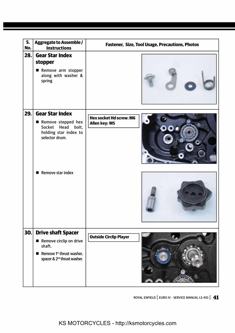
28. Gear Star Indexstopper Remove stepped bolt
holding arm stopper toCrankcase.
Stepped Bolt: M8Hex Socket: 10mm
KS MOTORCYCLES - http://ksmotorcycles.com
ROYAL ENFIELD EURO IV - SERVICE MANUAL LS 410 41
28. Gear Star Indexstopper Remove arm stopper
along with washer &spring
S.No.
Fastener, Size, Tool Usage, Precautions, PhotosAggregate to Assemble /Instructions
30. Drive shaft Spacer Remove circlip on drive
shaft.
Remove 1st thrust washer,spacer & 2nd thrust washer.
Outside Circlip Player
Hex socket Hd screw: M6Allen key: M5
29. Gear Star Index Remove stepped hex
Socket Head bolt,holding star index toselector drum.
Remove star index
KS MOTORCYCLES - http://ksmotorcycles.com

ROYAL ENFIELD EURO IV - SERVICE MANUAL LS 41042
31. Auto chaintensioner Remove hex bolt with
spring from the center ofauto chain tensionerbody.
Remove 2 hex sockethead screws &gentlypull out auto chaintensioner assembly.
Remove gasket.
S.No.
Fastener, Size, Tool Usage, Precautions, PhotosAggregate to Assemble /Instructions
Hex flange bolt: M8Hex Socket: 12mm
CAUTION:Open slowly &carefully sincespring loaded bolt.
NOTE:Ensure ‘O’ ring is removedfrom housing.
Hex Socket Hd screw:M6 X 25Allen Key: M5
32. Inlet manifold Remove 2 hex socket
head screws.
Remove inlet manifoldwith “O” ring
Hex Socket HdScrew:M6X25Allen key: M5
KS MOTORCYCLES - http://ksmotorcycles.com

ROYAL ENFIELD EURO IV - SERVICE MANUAL LS 410 43
33. Cover- Cam Center Remove 2 hex flange
bolts & remove cover
S.No.
Fastener, Size, Tool Usage, Precautions, PhotosAggregate to Assemble /Instructions
35. Tappet cover inlet Remove 2 hex flange
bolts & remove coverwith O ring.
Hex flange bolts: M6X21Hex Socket: 8mm
Hex flange bolts: M6 X 16Hex Socket: 8mm
34. Plug - CamshaftHole Remove hex flange bolt.
Rotate plug clock-wise gently. DO NOTATTEMPT to removeplug forcefully from thecylinder head cover.
Hex flange bolt: M6 X 16Hex Socket: 8mm
NOTE:The plug will be tight incylinder head cover.
Do not attempt to removebefore loosening all thecylinder head cover bolts.
KS MOTORCYCLES - http://ksmotorcycles.com

ROYAL ENFIELD EURO IV - SERVICE MANUAL LS 41044
36. Tappet coverexhaust Remove 2 hex flange
bolts & remove coverwith O ring.
S.No.
Fastener, Size, Tool Usage, Precautions, PhotosAggregate to Assemble /Instructions
38. Cylinder head cover Remove 2 long hex
flange bolts withaluminum washers fromthe top RH side.
Remove 3 long hexflange bolts from the topLH side
Hex flange bolts: M6X21Hex Socket: 8mm
37. Plugs rocker shafts Loosen 2hex socket
head plugs from cylinderhead cover RH side.(Donot remove plugs fully)
Hex Socket plug: M14 X 12Allen key: M8
Hex flange bolt: M6 X 60Hex Socket: 8mm
Hex flange bolt: M6 X 60Hex Socket: 8mm
NOTE:Aluminum washers areprovided to prevent oil leakthrough the bolts.
KS MOTORCYCLES - http://ksmotorcycles.com

ROYAL ENFIELD EURO IV - SERVICE MANUAL LS 410 45
S.No.
Fastener, Size, Tool Usage, Precautions, PhotosAggregate to Assemble /Instructions
38. Cylinder head cover Remove 3 medium Hex
flange bolts from the LHside.
Remove 2 long Hexflange bolts from RHside.
Remove 2 fully threadedHex flange bolts frominlet & Exhaust tappetsopening.
39. Plug camshaft hole Remove small cam shaft
cover.
Hex bolt: M6X55HexSocket: 8mm
Hex flange bolt: M6 X 40 EXHex flange bolt: M6 X 45 INHex Socket: 8mm
Hex bolt: M6X16Hex Socket: 8mm
KS MOTORCYCLES - http://ksmotorcycles.com

ROYAL ENFIELD EURO IV - SERVICE MANUAL LS 41046
40. Cylinder head cover Remove cylinder head
cover by gently tappingon the pegs provided.
S.No.
Fastener, Size, Tool Usage, Precautions, PhotosAggregate to Assemble /Instructions
42. Shaft - Rocker arms Locate 2 long suitable
M8 hex screws into therocker shaft threads &pull out the shafts.
41. Rocker Shaft Plugscrews Remove the 2 hex socket
plug screws (Loosenedearlier) with their copperwashers from thecylinder head cover.
Hex flange bolts: M8Hex Socket: 10mm
43. Rocker arms Remove inlet & exhaust
rocker arms.
KS MOTORCYCLES - http://ksmotorcycles.com

ROYAL ENFIELD EURO IV - SERVICE MANUAL LS 410 47
44. Spark plug Remove spark plug from
cylinder head.
S.No.
Fastener, Size, Tool Usage, Precautions, PhotosAggregate to Assemble /Instructions
45. Cam shaft assembly Rotate cam shaft such
that the half lock washerwill come up from thecylinder head slot.
Remove the half washer.
Rotate Cam shaft ifnecessary such that Onehex bolt can be accessedfor loosening.
Straighten lock tab &remove 1st hex bolt.
Hex bolt: M6 X 12Hex Socket: 10mm
Spark plug M10Deep Hex Socket 16mm
KS MOTORCYCLES - http://ksmotorcycles.com

ROYAL ENFIELD EURO IV - SERVICE MANUAL LS 41048
45. Cam shaft assembly Rotate Cam shaft to
access the 2nd hex bolt.
Straighten lock tab &remove hex bolt, alongwith lock plate.
Release sprocket fromthe dowel in cam shaft toincrease chain slack.
Release cam chain fromthe Sprocket by liftingand pushing it behindthe sprocket.
Lift cam shaft andremove sprocket.
Remove cam shaft.
S.No.
Fastener, Size, Tool Usage, Precautions, PhotosAggregate to Assemble /Instructions
CAUTION:Ensure the Lock tab andwasher does not drop intothe cam chain
NOTE:Hold chain securely, toprevent it from droppinginto cylinder head.
KS MOTORCYCLES - http://ksmotorcycles.com

ROYAL ENFIELD EURO IV - SERVICE MANUAL LS 410 49
46. Cylinder headassembly Remove 4 Long hex
bolts from insidecylinder head
Remove 2 hex flangebolts from the LH side ofthe cylinder head cover.
Gently tap and lift upcylinder head, takingcare not to drop the camchain into cylinderbarrel.
S.No.
Fastener, Size, Tool Usage, Precautions, PhotosAggregate to Assemble /Instructions
47. Cylinder headgasketRemove cylinder head
gasket.
NOTE:2 dowels are provided incylinder barrel to locate thecylinder head.
Hex bolt: M10 X 170Hex Socket: 12mm
NOTE:Take care not to dropthefour thick washers fromthe bolts.
Hex flange bolts: M6 X 30Double end spanner: 8mm
KS MOTORCYCLES - http://ksmotorcycles.com

ROYAL ENFIELD EURO IV - SERVICE MANUAL LS 41050
48. Valves in CylinderHead Locate valve spring
compressor tool on inletvalve such that thesleeve with screw isresting on the retainervalve spring & thebottom of the tool iscentrally located on thevalve.
Tighten special tool tillsprings are compressedfully & the cotters arefree from the valvestem.·
Remove both cotters &loosen special tool tillsprings are fullyexpanded & tool can beeasily removed.
Remove special tool,retainer, outer spring,inner spring & springseat from the cylinderhead.·
Remove inlet valve bypulling it from bottom ofcylinder head.
Remove Valve stem sealsfrom the valve guidetop.
Repeat above procedureto dismantle exhaustvalve.
S.No.
Fastener, Size, Tool Usage, Precautions, PhotosAggregate to Assemble /Instructions
49. Chain guide pads Remove chain guide pad
located in the front onthe cylinder head, bypulling it from the top.
Special Tool: ST-27528-2Valve Spring CompressorTool
CAUTION:Ensure special tool iscorrectly located beforeattempting to compressvalve springs.
NOTE:Ensuresplit collars areremoved before releasingsprings
NOTE:The valve guides & valveseat inserts should not beremoved from cylinderhead OR reworked as it willaffect engine performance.In the event of any wearout, complete cylinderhead assy. should only bereplaced
KS MOTORCYCLES - http://ksmotorcycles.com

ROYAL ENFIELD EURO IV - SERVICE MANUAL LS 410 51
49. Chain guide pads Release the cam chain
from the sprocket oncrankshaft and removefrom the engine.
RemoveBolt- Stepped,holding chain tensionerpad to crankcase LH.
Remove fixed chainguide pad from the top.
S.No.
Fastener, Size, Tool Usage, Precautions, PhotosAggregate to Assemble /Instructions
50. Cylinder barrelassembly Remove 2 hex flange
nuts on LH side ofcylinder barrel.
Gently lift cylinder barrelup to remove frompiston.
Remove cylinder basegasket.
Locate special tool onconnecting rod belowpiston on inlet side, tosupport piston
Hex flange nut: M6Double end spanner:8mm
Bolt Stepped: M6 X 14Allen Key: 5
CAUTION:Take care to remove thewasher behind the chaintensioner pad.
NOTE:Ensure the 2 dowels areremoved from crankcaseLH. / cylinder barrel
Special Tool: ST-27529-2Piston support specialtool.
KS MOTORCYCLES - http://ksmotorcycles.com

ROYAL ENFIELD EURO IV - SERVICE MANUAL LS 41052
51. Piston Pin Remove circlip from one
side of piston & push outgudgeon pin fromopposite side.
Remove Piston fromConnecting rod
S.No.
Fastener, Size, Tool Usage, Precautions, PhotosAggregate to Assemble /Instructions
53. Oil Jet Cylinderbarrel seating area Remove oil jet from RH
Crankcase / barrelseating area.
52. Piston rings Remove piston rings by
expanding the rings attheir open ends slightly &lifting towards the top ofthe piston.
54. Oil Jet - CrankcaseLH (outside) RemoveHex socket head
screw from CrankcaseLH
Special Tool: ST-27529-2Piston support specialtool.
NOTE:Do not expand rings toomuch since they will break!
The oil control ring is a 3piece set.
Hex Socket Hd Screw:M6 X 12Allen Key: M5
KS MOTORCYCLES - http://ksmotorcycles.com

ROYAL ENFIELD EURO IV - SERVICE MANUAL LS 410 53
54. Oil Jet - CrankcaseLH (outside) Gently pull out & remove
oil jet.
S.No.
Fastener, Size, Tool Usage, Precautions, PhotosAggregate to Assemble /Instructions
NOTE:Ensure the small ‘O ’ring isremoved from seating areain crankcase / behind oil jet.
55. CrankcaseFastenersRemove Hex socket head screw
from crankcase LHfront.
3 hex bolts from crank-case LH magneto area.
1 Hex flange bolt from LHcrankcase near startermotor housing.
Hex Socket Hd Screw:M6X 12Allen Key: M5.
Hex bolt: M8 X 70Hex Socket: 12mm
Hex bolt: M6 X 60Hex Socket: 8mm
NOTE:8 Hex Bolts (1 near Startermotor housing, 4 in front &3 at bottom are shorter &same length.)
6 Hex bolts on rear end arethe longest
KS MOTORCYCLES - http://ksmotorcycles.com

ROYAL ENFIELD EURO IV - SERVICE MANUAL LS 41054
55. CrankcaseFastenersRemove 4 Hex flange bolts from
LH crankcase front.
6 Hex bolts (Longest)from LH crankcase rear.
3 Hex bolts from crank-case LH bottom
S.No.
Fastener, Size, Tool Usage, Precautions, PhotosAggregate to Assemble /Instructions
56. Crankcases splitting Split crankcases by
locating 2 suitable shortHex bolts with nuts,between the front & reartabs on the crankcases.
Unscrew nuts evenlysuch that the crank-cases separate.
Gently tap on the tabsusing small plastic malletto separate crankcasesfurther.
Hex bolt: M6 X 60Hex Socket: 8mm
Hex Flange bolt: M6 X 85Hex Socket: 10mm
Hex bolt: M6 X 60Hex Socket: 8mm.
KS MOTORCYCLES - http://ksmotorcycles.com

ROYAL ENFIELD EURO IV - SERVICE MANUAL LS 410 55
57. Crankcase RHremoval Remove Crankcase RH
from the shafts by gentlytapping on the shaftssimultaneously, using asmall plastic mallet
S.No.
Fastener, Size, Tool Usage, Precautions, PhotosAggregate to Assemble /Instructions
59. Crank shaftAssembly Remove crank shaft
assembly by slightlyrotating & tapping fromLH side (magneto side).
NOTE:The LH shaft main bearingis integral with the crankshaft assembly, henceshould NOT be removed orserviced separately.
NOTE:Please ensure thrustwasher on counter shaftdoes not fall off
58. Balancer shaftassembly Gently tap balancer
shaft out of the bearingfrom the CrankcaseLH.(Partial blind hole)
NOTE:The gear has a highinterference fit in balancershaft and hence cannot beseparated from the shaft.
KS MOTORCYCLES - http://ksmotorcycles.com

ROYAL ENFIELD EURO IV - SERVICE MANUAL LS 41056
60. Oil Jet -crankcaseLH(inside) RemoveHex socket head
screw from CrankcaseLH.
Gently pull out & removeoil jet.
S.No.
Fastener, Size, Tool Usage, Precautions, PhotosAggregate to Assemble /Instructions
Hex Socket Head Screw:M6X12Allen Key: M5
NOTE:Ensure the small ‘O ’ring isremoved from seating areain crankcase / behind oil jet.
61. Gear OperatorForks Remove the 2 spindles
holding the operatorforks to the gear drumassembly.
Remove three operatorforks from the gears.
NOTE:Both the long operatorforks are located towardsthe rear end of crank case &the small operator fork atthe center.
The forks are numbered 1,2 & 3 for easy identification.
KS MOTORCYCLES - http://ksmotorcycles.com

ROYAL ENFIELD EURO IV - SERVICE MANUAL LS 410 57
62. Gear shifter drum Remove gear shifter
drum from crankcase LH
S.No.
Fastener, Size, Tool Usage, Precautions, PhotosAggregate to Assemble /Instructions
63. Drive shaftassembly Remove thrust washer
· Remove 1st gear withfloating bush.
Remove thrust washer
KS MOTORCYCLES - http://ksmotorcycles.com

ROYAL ENFIELD EURO IV - SERVICE MANUAL LS 41058
63. Drive shaftassembly Remove 5thgear.
Gently tap drive shaftfrom the LH side &remove from crankcaseLH.
Remove drive shaftspacer from crankcaseLH outside.
S.No.
Fastener, Size, Tool Usage, Precautions, PhotosAggregate to Assemble /Instructions
Caution:The bush will be tight ondrive shaft, due to the ‘O’ring inside the bush.
Gently tap the shaft toremove from crankcase LH.
Take care not to damagethe threads while tappingon the shaft.
64. Gears in drive shaft Remove circlip.
External circlip pliers
KS MOTORCYCLES - http://ksmotorcycles.com

ROYAL ENFIELD EURO IV - SERVICE MANUAL LS 410 59
64. Gears in drive shaft Remove thrust washer
with 3 lugs.
Remove 4th gear
Remove bush withinternal splines.
Remove splined washerwith outside tabs.
S.No.
Fastener, Size, Tool Usage, Precautions, PhotosAggregate to Assemble /Instructions
KS MOTORCYCLES - http://ksmotorcycles.com

ROYAL ENFIELD EURO IV - SERVICE MANUAL LS 41060
64. Gears in drive shaft Rotate thrust washer
with internal splinessuch that the splines arefree to move in the shaft& remove washer fromshaft.
Remove 3rd gear.
Remove splined bush.
Remove thrust washer.
S.No.
Fastener, Size, Tool Usage, Precautions, PhotosAggregate to Assemble /Instructions
KS MOTORCYCLES - http://ksmotorcycles.com

ROYAL ENFIELD EURO IV - SERVICE MANUAL LS 410 61
·
64. Gears in drive shaft Remove circlip.
Remove sliding bush.
Remove circlip
Remove collared bush.
S.No.
Fastener, Size, Tool Usage, Precautions, PhotosAggregate to Assemble /Instructions
Externalcirclip pliers
KS MOTORCYCLES - http://ksmotorcycles.com

ROYAL ENFIELD EURO IV - SERVICE MANUAL LS 41062
64. Gears in drive shaft Remove 2nd gear.
S.No.
Fastener, Size, Tool Usage, Precautions, PhotosAggregate to Assemble /Instructions
CAUTION:Ensure thrust washer onmain shaft does not getmisplaced while removingmain shaft
65. Counter shaftassembly Pull out main shaft with
gears from crankcaseLH.
External circlippliers
66. Gears in countershaft Remove 2ndgear.
Remove circlip.
KS MOTORCYCLES - http://ksmotorcycles.com

ROYAL ENFIELD EURO IV - SERVICE MANUAL LS 410 63
66. Gears in countershaft Remove 3rd& 4thsliding
gears.
Remove thrust washer.
Remove circlip.
Remove 5th gear.
S.No.
Fastener, Size, Tool Usage, Precautions, PhotosAggregate to Assemble /Instructions
Externalcirclip pliers
KS MOTORCYCLES - http://ksmotorcycles.com

ROYAL ENFIELD EURO IV - SERVICE MANUAL LS 41064
66. Gears in countershaft Remove bush.
S.No.
Fastener, Size, Tool Usage, Precautions, PhotosAggregate to Assemble /Instructions
NOTE:1st gear is integralwith main shaft
Hex bolt: M6 X 10Hex Socket: 10mm
67. Crankcase LH oilseals Open lock tabs and
remove 2 Hex boltsalong with lock platefrom crankcase LHouter side.
Remove drive shaft oilseal from the crankcaseLH outer side.
Remove gear shift shaftdouble lipped oil sealfrom crankcase LHouter side.
KS MOTORCYCLES - http://ksmotorcycles.com

ROYAL ENFIELD EURO IV - SERVICE MANUAL LS 410 65
68. Crankcase RHbearingsA. Selector drum bearing:
· Remove 2 hex sockethead screws withretainer plates fromcrankcase RH outer side.
Using a suitable drift,drive out the ball bearingfrom the inner side ofcrankcase RH.
B. Drive shaft bearing:
· Using a suitable drift,drive out the ball bearingfrom the outer side ofcrankcase RH.
C. Counter shaft bearing:
Remove hex sockethead screw along withretainer platefrom theinner side of crankcaseRH.
Using a suitable drift,drive out the ball bearingfrom the outer side ofcrankcase RH.
D. Crankshaft bearing:
Using a suitable drift,drive out the ball bearingfrom the outer side ofcrankcase RH.
S.No.
Fastener, Size, Tool Usage, Precautions, PhotosAggregate to Assemble /Instructions
Hex Socket Hd. Screw:M6 X 12Allen Key: M5
Bearing drift & plasticmallet.
Hex Socket Head Screw:M6 X 12Allen Key: M5
Bearing drift & plasticmallet.
KS MOTORCYCLES - http://ksmotorcycles.com

ROYAL ENFIELD EURO IV - SERVICE MANUAL LS 41066
68. Crankcase RHbearingsE. Balancer shaft bearing:
Use a suitable drift todrive the ball bearing outfrom the outer side ofcrankcase RH.
S.No.
Fastener, Size, Tool Usage, Precautions, PhotosAggregate to Assemble /Instructions
Bearing drift & plasticmallet.
69. Crankcase LHbearingsA. Drive shaft bearing:
Using a suitable drift,drive out the ball bearingfrom the outer side ofcrankcase LH.
B. Counter shaft bearing:
· Use a suitable two jawpuller to pull out the ballbearing from the blindhole inside crankcaseLH.
C. Balancer shaft bearing:
Using a suitable drift,drive out the ball bearingfrom the outer side ofcrankcase LH.
Bearing drift & plasticmallet.
Two Jaw puller.
Bearing drift & plasticmallet.
KS MOTORCYCLES - http://ksmotorcycles.com

ROYAL ENFIELD EURO IV - SERVICE MANUAL LS 410 67
WEAR LIMITS - LS 410
New components must be within the limits specified. Components within service limits may be reused after carefulinspection. Use of parts beyond service limit can reduce the operating life of the component and affect the motorcycleperformance seriously. (All units in mm unless specified)
Cylinder Bore ID Top, Middle & Bottom of Piston working area 78.000 78.030 78.100Piston OD Top, Middle & Bottom of piston 77.940 77.970 77.870Cylinder Bore/Piston Clearance 0.015 0.040 0.20Piston ring top 1 Rings End Gap in Bore at the topmost ring 0.15 0.30 0.60Piston ring top 2 working area in bore. 0.20 0.40 0.70Top ring Clearance between Piston ring 0.03 0.07 0.10Middle ring groove & piston rings in 0.03 0.07 0.10Oil scrapper ring assembled condition 0.03 0.07 0.10Balancer Shaft Run out - 0.03 0.05Crankshaft Assembly Crankshaft assembly run out - 0.05 0.09Crankshaft Assembly Big End Axial Play - - 0.065Piston Pin Piston Pin Diameter 19.992 19.997 19.977Connecting rod Connecting rod small end ID 20.010 20.019 20.050Cylinder head / cover Warpage - - 0.01Cylinder head / barrel Warpage - - 0.01Valve guide Inlet
Internal ID7.000 7.015 7.070
Valve guide Exhaust 7.000 7.015 7.100Valve stem Inlet
Stem OD6.960 6.975 6.945
Valve stem Exhaust 6.945 6.960 6.920Valve / Guide Inlet
Valve stem to Guide Clearance0.01
Valve / Guide Exhaust 0.14Valve seat/valve Contact area 1.00 1.50Valve Spring Inner
Overall Length36.70 34.70
Valve Spring Outer 43.90 41.90Cam shaft Run out 0.02 0.05Camshaft Journal Dia 21.959 21.980 21.930Camshaft Journal Bore Dia 21.988 22.025 22.088Camshaft Journal Oil groove clearance - - 0.05Cam Lobe Lobe Height 36.92 36.96 36.76Clutch Spring Free Length 33.60 32.60Clutch Steel Plate Thickness 1.550 1.650 1.533Clutch Friction Plate Thickness 2.950 3.050 2.830Clutch Steel/
Distortion 0.10 0.30Friction PlatesShifter Drum Groove width 6.05 6.20 6.30
Shifter ForksGuide Pin Dia 5.85 5.95 5.75Lug Thickness 5.30 5.40 5.20
Component Where / What to Measure Minimum Maximum Service Limit
KS MOTORCYCLES - http://ksmotorcycles.com

ROYAL ENFIELD EURO IV - SERVICE MANUAL LS 41068
TORQUE VALUES - LS 410
Aggregate Component Fastener Qty Torque Range (Nm) (Kg. M)
Piston Oil Jet Hex Socket Head Screw M6 X 12 1 8 - 12 0.8 – 1.2
Starter Clutch Oil Jet Hex Socket Head Screw M6 X 12 1 8 - 12 0.8 – 1.2
Cam Chain Tensioner Pad Bolt Stepped - M6 X 14 1 10 - 12 1.0 – 1.2
Gear Position Switch Hex Flange Bolt - M6 X 16 2 6.8Max 0.68Max
Crankcase LH Side Oil Strainer Cap Hex Flange Bolt - M6 X 20, 2 8 - 12 0.8 – 1.2
Oil Passage Hex Flange Bolt - M8 X 12 3 20 - 24 2.0 – 2.4
Crankcase Drain Plug M14 X 12 1 20 - 25 2.0 – 2.5
Drive Shaft Oil Seal Retainer Hex Bolt - M6 X 10 2 8 - 12 0.8 – 1.2
Final Drive Sprocket Hex Nut M20 1 130 - 160 13 - 16
Sprocket Cover Hex Flange Bolt - M6 X 35 2 8 - 12 0.8 – 1.2
MagnetoRotor Ring Assembly Hex Socket Head Screw M6X20 6 10 - 12 1.0 – 1.2
Magneto Rotor Hex Flange Nut M12 X1.25 X 11 1 70 - 80 70 – 8.0
Clamp, Stator Wire Hex Socket Head Screw M5 X 15 2 8 - 10 0.8 – 1.0
Stator Coil Screw Hex Socket Head Screw M5 X 30 3 8 - 10 0.8 – 1.0
Cover LH TDC Inspection Plug Plug – M14 X 12 1 20 - 25 2.0 – 2.5
Cover LH MountingHex Flange Bolt - M6 X 35 8 8 - 12 0.8 – 1.2
Hex Flange Bolt - M6 X 55 3 8 - 12 0.8 – 1.2
Cover LH Logo Hex Socket Head Screw M6 X 21 2 8 - 12 0.8 – 1.2
Hex Socket Head Screw M8X 100 1 20 - 24 2.0 – 2.4
Crankcase boxingHex Flange Bolt- M8 X 70 3 20 - 24 2.0 – 2.4
Crankcase LH & RH Hex Flange Bolt - M6 X 85 6 8 - 12 0.8 – 1.2
Hex Flange Bolt – M6 X 60 8 8 - 12 0.8 – 1.2
Starter Motor Hex Flange Bolt - M6 X 30 2 10 - 12 1.0 – 1.2
Cam Drum Bearing Retainer Hex Socket Head Screw M6 X 12 2 8 - 12 0.8 – 1.2
Oil Pump Hex Flange Bolt - M6 X 30 4 7 - 9 0.7 – 0.9
Crankcase RH Stopper, Gear Shift Arm Hex Flange bolt M8 1 10 - 12 1.0 – 1.2
Pump Drive Gear Nut (LH Thread) M18 1 85 - 90 8.5 – 9.0
Balancer Shaft Hex Flange Bolt - M10 X 20 1 40 - 60 4.0 – 6.0
Clutch Center Hex Nut M20 1 40 - 60 4.0 – 6.0
Gear shiftingStar Index Hex Socket Head, Stepped Bolt 1 10 - 12 1.0 – 1.2
Gear Shift Cam Stopper Hex Bolt Stepped 1 10 - 12 1.0 – 1.2
KS MOTORCYCLES - http://ksmotorcycles.com

ROYAL ENFIELD EURO IV - SERVICE MANUAL LS 410 69
Aggregate Component Fastener Qty Torque Range (Nm) (Kg. M)
Cover Oil Jet Seal Retainer Hex Socket Head Screw M6 X 12 1 8 - 12 0.8 – 1.2
Clutch shaft spring. Hex Flanged Bolt– M6 X 10 1 10 - 12 1.0 – 1.2
Hex Flange Bolt - M6 X 37 8 8 - 12 0.8 – 1.2
Cover RHCover RH Hex Flange Bolt M6 X 30 5 8 - 12 0.8 – 1.2
Hex Flange Bolt – M6 X 20 1 8 - 12 0.8 – 1.2
Cap – Oil FilterHex Flange Bolt - M6 X 70 1 8 - 12 0.8 – 1.2
Hex Flange Bolt - M6 X 20 2 8 - 12 0.8 – 1.2
Plug, Oil Check Plug– M14 X 12 1 20 - 25 2.0 – 2.5
Cylinder Head Special Hex Bolts - M10 X 170 4 40 - 45 4.0 – 4.5
Camshaft & Sprocket Lock Hex Bolt – M6 X 12 2 10 - 12 1.0 – 1.2
Cylinder Head Side Mount Hex Flange Bolt – M6 X 2 8 - 12 0.8 – 1.2
Cylinder Head De Compressor Fly Weight Hex Socket Head Screw 1 3 - 5 0.3 – 0.5
PAV Pipe Mounting Hex Socket Head Screw M X 2 8 - 12 0.8 – 1.2
Spark Plug Spark Plug (M10) - CR8E 1 10 - 15 1.0 – 1.5
Adapter Carb To Cyl Head Hex Socket Head Screw- M6 2 8 - 12 0.8 – 1.2
Cylinder barrel side Mount Hex Flange Nut M6 X 1 2 8 - 12 0.8 – 1.2
Cylinder Barrel Auto Chain Tensioner Mtg Hex Socket Head Screw M6 X 25 2 10 - 12 1.0 – 1.2
& Spring bolt Special Hex Bolt M 8 1 8 - 10 0.8 – 1.0
Hex Flange Bolt - M6 X 60 5 10 - 14 1.0 – 1.4
Hex Flange Bolt - M6 X 55 3 10 - 14 1.0 – 1.4
Cylinder Head CoverHex Flange Bolt - M6 X 45 1 10 - 14 1.0 – 1.4
Cylinder Head Cover Hex Flange Bolt - M6 X 40 1 8 - 12 0.8 – 1.2
Hex Flange Bolt - M6 X 20 6 8 - 12 0.8 – 1.2
Hex Flange Bolt - M6 X 21 2 8 - 12 0.8 – 1.2
Tappet Cover Hex Flange Bolt-M6 X 21 4 8 - 12 0.8 – 1.2
Plug, Camshaft Hole Hex Flange Bolt - M6 X 16 1 8 - 12 0.8 – 1.2
Cam CoverRocker Shaft Plugs Hex Socket Head Plug-M14 X 12 2 25 - 30 2.5 – 3.0
Cover- Cam Center Hex Flange Bolt - M6 X 16 2 8 - 12 0.8 – 1.2
Oil CoolerOil Cooler Pipe banjo Bolt, Union M 2 35 - 38 3.5 – 3.8
Oil Cooler pipe Mtg Hex Socket Head Screw M 4 8 - 12 0.8 – 1.2
KS MOTORCYCLES - http://ksmotorcycles.com

ROYAL ENFIELD EURO IV - SERVICE MANUAL LS 41070
PRECAUTIONS BEFORE ENGINE REASSEMBLY
Please ensure all parts are thoroghly cleaned and stored in a sequence for inspection
and reassembly.
Lubricate all moving parts prior to reassembly.
Replace parts like: Gaskets, “O” Rings, Oil seals, Dust seals, Rubber items, Aluminum
washers, Circlips whenever they are removed OR during a complete engine overhaul.
NOTE:
While fixing bearings, bushes or oil seals, it is NOT necessary to heat theCrankcase.
KS MOTORCYCLES - http://ksmotorcycles.com

ROYAL ENFIELD EURO IV - SERVICE MANUAL LS 410 71
1. Crankcase LHBearingsA. Balancer shaft
Bearing:·
Locate bearing inCr ankc ase LH frominnerside & gently tapusing a suitable drift andplastic mallet
.
B. Counter shaft bearing:
· Locate bearing in theblind hole in CrankcaseLH fromi nner side &gently tap using asuitable drift and plasticmallet
C. Drive shaft bearing:
Locate bearing in Crank-case LH from innerside& gently tap using asuitable drift and plasticmallet
Bearing drift & plasticmallet.
NOTE:Ensure bearing outer raceis flush with housing incrank case after pressingthe bearings.
ENGINE ASSEMBLY SEQUENCE
S.No.
Fastener, Size, Tool Usage, Precautions, PhotosAggregate to Assemble /Instructions
KS MOTORCYCLES - http://ksmotorcycles.com

ROYAL ENFIELD EURO IV - SERVICE MANUAL LS 41072
2. Crankcase RHBearingsA . Balancer shaft
bearing:
Locate bearing incr ankc ase RH frominner side & gently tapusing a suitable drift andplastic mallet.
B. Crankshaft bearing:
Locatebearing inc rankcase RH frominner side & gently tapusing a suitable drift andplastic mallet.
C. Counter ShaftBearing:
Locate bearing in crank-case RH from inner side& gently tap using asuitable drift and plasticmallet.
Position retainer platebetween the slots incrankcase RH & tightenwith Hex Socket Headscrew.
S.No.
Fastener, Size, Tool Usage, Precautions, PhotosAggregate to Assemble /Instructions
Bearing drift & plasticmallet.
NOTE:Ensure bearing outer raceis flush with housing incrank case after pressingthe bearings.
Hex socket hd. screw:M6X12Allen Key: 5mmTorque: 0.8-1.2Kg.M(8-12 Nm)
NOTE:Ensure retainer plate isproperly located overbearing outer race, beforetightening screw.
KS MOTORCYCLES - http://ksmotorcycles.com

ROYAL ENFIELD EURO IV - SERVICE MANUAL LS 410 73
2. Crankcase RHBearingsD . Drive Shaft Bearing:
Locate bearing incr ankc ase RH frominner side& gently tapusing a suitable drift andplastic mallet.
E. Gear selector drumbearing.
Locate bearing inCr ankc ase RH fromouter side& gently tapusing a suitable drift andplastic mallet.
Position two retainerlatesbetween the slots incrankcase RH & tightenwith Hex Socket Headscrews.
S.No.
Fastener, Size, Tool Usage, Precautions, PhotosAggregate to Assemble /Instructions
3. Crankcase LH OilsealsA . Gear shift shaft oil
seal.
Locate double lip oil sealin Crankcase LH fromouter side& gently tapusing a suitable drift andplastic mallet.
Bearing drift & plasticmallet.
Hex socket hd screw:M6 X 12Allen Key: 5mmTorque: 0.8-1.2Kg.M(8-12 Nm)
Bearing drift & plasticmallet.
NOTE:Ensure retainer plate isproperly located overbearing outer race, beforetightening screw.
NOTE:Ensure oil seal outer face isfacing outside & is flushwith housing in crank case.
KS MOTORCYCLES - http://ksmotorcycles.com

ROYAL ENFIELD EURO IV - SERVICE MANUAL LS 41074
3. Crankcase LH OilsealsB. Drive shaft oil seal: Locate oil seal on crankcase
LH from outer side& gentlytap using a suitable drift andplastic mallet.
Locate retainer plate over oilseal & tighten in positionwith 2 Hex bolts.
Bend the retainer plate locktabs over the hex bolts, toprevent them fromloosening
S.No.
Fastener, Size, Tool Usage, Precautions, PhotosAggregate to Assemble /Instructions
NOTE:Ensure oil seal outer face isfacing outside & is flushwith housing in crank case.
NOTE:Apply grease on ‘O’ ring tohold it in place.
Hex Socket Hd Screw:M6 X 12Allen key: 5mmTorque: 0.8-1.2Kg M (8-12Nm)
4. Piston Oil Jet Locate ‘O’ ring in crank-
case LH inside.
Locate oil jet in crank-case LH inside with itsspout facing upwards
Tighten with Hex SocketHead screw.
Hex Bolt: M6 X 10Hex Socket spanner: 8mmTorque: 0.8-1.2Kg.M (8-12Nm)
KS MOTORCYCLES - http://ksmotorcycles.com

ROYAL ENFIELD EURO IV - SERVICE MANUAL LS 410 75
5. Starter Clutch OilJet. Locate ‘O’ ring in Crank-
case LH outside.
Locate oil jet in Crank-case LH outside with itsspoutfacing downwards.
Tighten with Hex SocketHead screw.
S.No.
Fastener, Size, Tool Usage, Precautions, PhotosAggregate to Assemble /Instructions
6. Sub Assembly ofgears in Drive Shaft Insert 2nd gear on the
shaft such that the smallrecess in the machinedside of the gear is seatedon the collar of the shaft.
Hex Socket Hd Screw:M6 X 12Allen key: 5mmTorque: 0.8-1.2KgM (8-12Nm)
NOTE:Apply grease on ‘O’ ring tohold it in place.
KS MOTORCYCLES - http://ksmotorcycles.com

ROYAL ENFIELD EURO IV - SERVICE MANUAL LS 41076
6. Sub Assembly ofgears in Drive Shaft Insert collared bush on
the shaft, such that thebush will enter into thegear and the collar isfacing outside andseated flush with thegear.
Assemble 1st circlip.
Insert bigger side of thesliding dog on the shaft,such that it is facing 2ndgear.
Assemble 2nd circlip.
S.No.
Fastener, Size, Tool Usage, Precautions, PhotosAggregate to Assemble /Instructions
OutsideCirclip Plier
OutsideCirclip Plier
KS MOTORCYCLES - http://ksmotorcycles.com

ROYAL ENFIELD EURO IV - SERVICE MANUAL LS 410 77
6. Sub Assembly ofgears in Drive shaft Assemble thrust washer
with three internalsplines on the shaft.
Align oil hole in thesplined bush with the oilhole in shaft and lower itfully.
Assemble 3rd gear on theshaft with its slot facingthe sliding dog.
Assemble thrust washerwith internal andexternal splines on theshaft, align the internaltabs with the groove inshaft, just above the 3rd
gear and rotate washersuch that the washerlocks in the shaft andcannot be removed.
S.No.
Fastener, Size, Tool Usage, Precautions, PhotosAggregate to Assemble /Instructions
CAUTION:Ensure oilhole in bushis alignedwith oil holein shaft.
KS MOTORCYCLES - http://ksmotorcycles.com

ROYAL ENFIELD EURO IV - SERVICE MANUAL LS 41078
6. Sub Assembly ofgears in Drive Shaft Assemble thrust washer
with outside tabs suchthat the tabs in thewasher locks into theslots in the thrustwasher.
Align oil hole in thesplined bush with the oilhole in shaft and lower itfully.
Insert 4thgear on theshaft, with the slot in thegear facing outside andlocate it on the splinedbush.
Assemble 2nd thrustwasher with the threeinternal splines.
S.No.
Fastener, Size, Tool Usage, Precautions, PhotosAggregate to Assemble /Instructions
CAUTION:Ensure oilhole in bushis alignedwith oil holein shaft.
KS MOTORCYCLES - http://ksmotorcycles.com

ROYAL ENFIELD EURO IV - SERVICE MANUAL LS 410 79
6. Sub Assembly ofgears in Drive shaft Assemble 3rd Circlip.
S.No.
Fastener, Size, Tool Usage, Precautions, PhotosAggregate to Assemble /Instructions
OutsideCirclip plier
7. Sub Assembly ofgears in countershaft Assemble bush on
counter shaft, from thenon-threaded end ofthe shaft.
Assemble 5thgear suchthat the lugs of the gearare towards the non-threaded end of thecounter shaft.
Assemble 1st thrustwasher.
KS MOTORCYCLES - http://ksmotorcycles.com

ROYAL ENFIELD EURO IV - SERVICE MANUAL LS 41080
7. Sub Assembly ofgears in countershaft Assemble 1st circlip.
Assemble3rd& 4thslidinggear on the shaft suchthat the larger gear isfacing the 5th gear.
Assemble 2nd circlip.
Assemble2ndgear.
S.No.
Fastener, Size, Tool Usage, Precautions, PhotosAggregate to Assemble /Instructions
NOTE:Larger gearmust betowards the1st gear.
OutsideCirclip plier
OutsideCirclip plier
NOTE:Collar in thegear shouldface towards1stgear.
KS MOTORCYCLES - http://ksmotorcycles.com

ROYAL ENFIELD EURO IV - SERVICE MANUAL LS 410 81
8. Counter shaftthrust washer Place thrust washer over
counter shaft bearing inCrankcaseLH.
S.No.
Fastener, Size, Tool Usage, Precautions, PhotosAggregate to Assemble /Instructions
NOTE:Apply grease on thrustwasher to preventit fromfalling off when locatingmain shaft.
NOTE:Ensure threaded end ofcounter shaft is facingupwards & threaded end ofmain shaft is inserted intoCrankcase LH.Gently tap both shafts intobearings simultaneouslyfor proper seating.
9. Counter shaft &Drive shaft inCrankcase LH Locate the shafts in their
respective locations inCrankcaseLH, ensuringthe gears in both shaftsare aligned.
10. Sub Assembly ofgears in Drive shaft Assemble5thgear such
that the gear side isfacing towards 1stgear.
Assemble thrust washer.
KS MOTORCYCLES - http://ksmotorcycles.com

ROYAL ENFIELD EURO IV - SERVICE MANUAL LS 41082
10. Sub Assembly ofgears in Drive shaft Assemble1stgear bush.
Assemble 1st gear overthe bush such that thedeep groove in 5th gear isfacing towards 1st gear.
Assemble thrust washerover 1st gear
S.No.
Fastener, Size, Tool Usage, Precautions, PhotosAggregate to Assemble /Instructions
NOTE:Ensure gears in bothcounter shaft & drive shaftare aligned.
11 Selector Forks Locate selector fork
No.2, inside sliding dogof on drive shaft, withthefork lug facingabove.
KS MOTORCYCLES - http://ksmotorcycles.com

ROYAL ENFIELD EURO IV - SERVICE MANUAL LS 410 83
11. Selector Forks Locate operator fork
No1 in the recess in driveshaft 5thgear.
Locate operator forkNo.3 in counter shaft on4thgear.
S.No.
Fastener, Size, Tool Usage, Precautions, PhotosAggregate to Assemble /Instructions
12. Gear Shift DrumAssembly Insert long end of Shift
Drum Assembly intoCrankcase LH. (thetwooffset pegs in the drumassy must be facingoutside.)
Lock selector forks inposition by locating thespindles in CrankcaseLH.
KS MOTORCYCLES - http://ksmotorcycles.com

ROYAL ENFIELD EURO IV - SERVICE MANUAL LS 41084
13. Crank shaftAssembly Locate bearing in the
housing in Crankcase LHand press crankshaftgently till the bearing isseated completely.
Rotate Crankshaft suchthat the crank webs areat their lowest position &the dot mark on the gearin crankshaft is facingtowards the front.
S.No.
Fastener, Size, Tool Usage, Precautions, PhotosAggregate to Assemble /Instructions
NOTE:Ensure dot marks oncrankshaft gear & balancershaft gear are matchedcorrectly.
NOTE:Smear oil on bearing outerrace.
Hold crankshaft vertically& ensure bearing enterscrankcase LH squarely.
14. Balancer shaftAssembly Position balancer shaft
such that the dot markon balancer shaft gearaligns with dot mark oncrankshaft gear andgently press balancershaft into the bearing incrankcase LH
NOTE:Apply Loctite No 5699 onthe mating surface of crankcase LH.
15. Crankcase Boxing Ensure Gasket sealant is
applied evenly anduniformly on the matingsurface of crankcase LH
Ensure dowels arelocated in crankcase LH.
Locate Crankcase RHover crankcase LH andgently tap it in whilegently rotating theshafts
Ensure Crankcase RH isfully seated over crank-case LH & all shafts arerotating freely.
KS MOTORCYCLES - http://ksmotorcycles.com

ROYAL ENFIELD EURO IV - SERVICE MANUAL LS 410 85
16. CrankcaseFastenersAssemble
Hex Socket Head screwin Crankcase LH belowBarrel seating area.
3 hex bolts in magnetoarea in crankcase LH.
1 Hex flange bolt incrankcase LH nearstarter motor housing
4 Hex flange bolts incrankcase LHfront.
6 Hex bolts (Longest) incrankcase LHrear.
S.No.
Fastener, Size, Tool Usage, Precautions, PhotosAggregate to Assemble /Instructions
Hex Socket Hd Screw:M8 X 100Allen key: M6Torque: 2-2.4KgM (20-24Nm)
Hex Flange Bolt- M8 X 70Socket spanner: 12mmTorque: 2-2.4KgM (20-24Nm)
Hex Flange Bolt- M6 X60 Socket spanner: 8mmTorque: 0.8-1.2KgM (8-12Nm)
Hex Flange Bolt- M6 X60 Socket spanner: 8mmTorque: 0.8-1.2KgM (8-12Nm)
Hex Flange Bolt- M6 X 85Socket spanner: 8mmTorque: 0.8-1.2KgM (8-12Nm)
KS MOTORCYCLES - http://ksmotorcycles.com

ROYAL ENFIELD EURO IV - SERVICE MANUAL LS 41086
16. CrankcaseFastenersAssemble
3 Hex bolts from crank-case LH bottom
S.No.
Fastener, Size, Tool Usage, Precautions, PhotosAggregate to Assemble /Instructions
Hex Flange Bolt- M6 X 60Socket spanner: 8mmTorque: 0.8-1.2KgM (8-12Nm)
NOTE:Ensure the words “TOP” 2in 2nd compression ring &“TOP 1” in 1st compressionring are facing towards thetop of the piston.
Lubricate rings well &position ring end gaps at120o to each other, for easyassembly of cylinder barrel.
NOTE:Ensure stiffener ring iscorrectly located betweenthe 2 oil Control rings.
17. Piston RingsAssembly Assemble Oil control ring
with stiffener ring in the3rd groove.
Assemble 2nd compressionring in the middlegroove.
Assemble 1st compressionring in the top mostgroove.
NOTE:Tighten all fasteners evenly &diagonally, for proper sealingof the crankcase joints
KS MOTORCYCLES - http://ksmotorcycles.com

ROYAL ENFIELD EURO IV - SERVICE MANUAL LS 410 87
18. Oil Jet Locate oil jet in Crank-
case RH, barrel seatingarea with its slotted endfacing up and press intocrank-case gently.
S.No.
Fastener, Size, Tool Usage, Precautions, PhotosAggregate to Assemble /Instructions
NOTE:Ensure ‘O’ ring does not getdamaged during assembly.
Ensure slotted end of jet isfacing outside.
NOTE:Apply grease on gasketseating surface.
19. Cylinder BarrelGasket Locate the two dowels
on Crankcase LH.
Locate gasket on Crank-case ensuring the recessfor the oil jet is correctlypositioned.
Caution:Gasket is unidirectionalhence ensure it is fittedcorrectly.
CAUTION:Ensure circlip locks in placeand does not fall intocrankcase.
Remove cloth afterassembling circlip.
20. Piston Assembly onConnecting Rod Assemble circlip on
piston, on one side &insert piston pin fromthe other side. Ensurethe pin is pressed justsufficiently into thepiston and notprotruding into piston
Support connecting rodusing special tool tohold it vertically forassembling piston.
Special Tool: ST-27529-2,Piston Support.
KS MOTORCYCLES - http://ksmotorcycles.com

ROYAL ENFIELD EURO IV - SERVICE MANUAL LS 41088
20. Piston Assembly onConnecting Rod Position piston on
connecting rod, ensuringthe piston pin holes inboth piston & connectingrod are aligned.
Lubricate piston pin &gently insert into pistontill it rests on the circlip
Cover crankcase spigotsuitably & assemble theother circlip on thepiston.
S.No.
Fastener, Size, Tool Usage, Precautions, PhotosAggregate to Assemble /Instructions
NOTE:Ensure marking, “EX” on thepiston is facing towardscrankcase front.
CAUTION:Ensure circlip locks in placeand does not fall intocrankcase.Remove cloth after assembl-ing circlip.
21. Cylinder Barrel onpiston Lubricate piston rings,
piston & cylinder barrel,with oil, for easy entry ofpiston into cylinderbarrel.
Ensure Piston issupported vertically.
Gently lower barrelover piston whiles i m u l t a n e o u s l ycompressing rings foreasy entry.
Remove piston support-ing tool & lower barrelfully into Crankcase.
KS MOTORCYCLES - http://ksmotorcycles.com

ROYAL ENFIELD EURO IV - SERVICE MANUAL LS 410 89
21. Cylinder Barrel onpiston Rotate Crank Shaft
Assembly to bringpiston to TDC.
Tighten barrel toCrankcase using 2Flanged Hex nuts on theLH side.
S.No.
Fastener, Size, Tool Usage, Precautions, PhotosAggregate to Assemble /Instructions
Hex Flange Nut: M6 X 1D E Spanner: 8 mmTorque: 0.8-1.2KgM (8-12Nm)
NOTE:Apply grease on cylinderhead gasket for properseating.
22. Cylinder headGasket Locate 2 dowels on
cylinder barrel top LHside.· Locate cylinderhead gasket over thecylinder barrel.
Stepped Hex socketBolt: M6X14Allen Key: M5Torque: 1.0 - 1.2KgM (10-12Nm)
23. Cam Chain Pads Insert chain tensioner
pad through cylinderbarrel.
Apply grease on thethrust washer to hold itin place over the threadedlocation in crankcase LH.
Position chain pad overthrust washer & tightenwith hex socket Headstepped bolt.
KS MOTORCYCLES - http://ksmotorcycles.com

ROYAL ENFIELD EURO IV - SERVICE MANUAL LS 41090
23. Cam Chain Pads Insert the cam chain
through the cylinderbarrel & locate it on thecrank shaft gear.
Ensure chain is properlysupported at the top toprevent it from droppinginto the crankcase.
Insert fixed cam chainpad through cylinderbarrel & locate it in thecrankcase LH
S.No.
Fastener, Size, Tool Usage, Precautions, PhotosAggregate to Assemble /Instructions
NOTE:Apply grease on the gear &chain to hold the chain inplace.
24. Valves in CylinderHead Insert inlet valve into
valve guide from insidecylinder head.
Assemble spring seat,inner spring, outerspring &retainer, fromthe top of cylinder head.
Locate valve springcompressing tool overthe retainer & compressspring till the valve stemcomes out through theretainer.
NOTE:Ensure fixed chain pad islocked in position in cylinderbarrel.as well as crankcaseLH.
NOTE:Ensure stem seals are fittedon the valve guide.
Ensure denser coils of thespring are seated on thespring seat in cylinder head.
KS MOTORCYCLES - http://ksmotorcycles.com

ROYAL ENFIELD EURO IV - SERVICE MANUAL LS 410 91
24. Valves in Cylinderhead. Insert split collars on
retainer. Ensure they areseated correctly againstvalve stem and retainer& release puller slowly.
Repeat above procedureto assemble exhaustvalve.
S.No.
Fastener, Size, Tool Usage, Precautions, PhotosAggregate to Assemble /Instructions
Special tool: ST-27528-2,Valve spring compressor.
NOTE:Apply grease on crankshaftsprocket & chain to hold itin place.
Secure chain from top toprevent it from droppinginto crankcase.
25. Cylinder HeadAssembly Position cylinder head
assembly over cylinderbarrel.
Holding the cam chainfrom the top, route itthrough the slot incylinder head bottomand locate the cylinderhead on the barrelcorrectly.
CAUTION:Ensuresplit collars arecorrectly locked betweenretainer & valve stem.
KS MOTORCYCLES - http://ksmotorcycles.com

ROYAL ENFIELD EURO IV - SERVICE MANUAL LS 41092
25. Cylinder HeadAssembly Locate 4 special Hex
bolts with washer &tighten diagonally.
Locate 2 Hex flange boltson cylinder head LHsideand tighten.
S.No.
Fastener, Size, Tool Usage, Precautions, PhotosAggregate to Assemble /Instructions
Special Hex Bolts:M10X170Hex Socket: 12mmTorque: 4-4.5KgM (40-45Nm)
26. Cam Chain &Sprocket Assembly Locate cam shaft along
with sprocket on cylinderhead.
Ensure sprocket is freeon cam shaft & locatechain on sprocket withmarking “T” on sprocketfacing up.
Rotate cam shaft,without disturbing thesprocket till the dowel inthe shaft aligns with thehole in the sprocket.
Ensure chain has noslack & Insert cam shaftinto sprocket such thatthe dowel locates intothe sprocket.
Hex flange bolts: M6X30D E Spanner: 8mmTorque: 0.8-1.2KgM(8-12Nm)
NOTE:Ensure Key way in crankshaftis facing up so that piston is atTDC on compression stroke.
CAUTION:- Ensure reference lines on
cam sprocket & camshaft are parallel &aligned.
- Crankshaft keyway is atTDC position.
KS MOTORCYCLES - http://ksmotorcycles.com

ROYAL ENFIELD EURO IV - SERVICE MANUAL LS 410 93
26. Cam Chain &Sprocket Assembly Fix 1 hex bolt with lock
plate on sprocket &tighten just sufficiently.
Rotate camshaft slowly& tighten 2nd Hex bolt,through the lock plate.
Tighten both bolts &bend lock plate over thebolts.
S.No.
Fastener, Size, Tool Usage, Precautions, PhotosAggregate to Assemble /Instructions
Hex Bolt: M6X12Hex Socket: 8 mmTorque: 1-1.2KgM (10-12Nm)
27. Cam Shaft Lock“C”washer. Align slot in cam shaft
with the groove incylinder head.
Insert “C” washer intocylinder head to lockaxial movement of thecam shaft
NOTE:Ensure “C” washer is locatedcorrectly into the slot incylinder head failing whichthe cylinder head covercannot seat properly
28. Auto Chain TensionerAssembly Ensure center bolt with
spring is removed fromassembly.
Release lock on chaintensioner body &depress pad completely.
NOTE:Ensure gasket is assembledon the Auto chain tensionerAssembly.
KS MOTORCYCLES - http://ksmotorcycles.com

ROYAL ENFIELD EURO IV - SERVICE MANUAL LS 41094
28. Auto Chain TensionerAssembly Locate chain tensioner
assembly in cylinderbarrel& tighten with 2Hex socket head screws.
Locate ‘O’ ring in thechain tensioner body.
Insert spring into chaintensioner and tightenwith special Hex bolt.
S.No.
Fastener, Size, Tool Usage, Precautions, PhotosAggregate to Assemble /Instructions
NOTE:Ensure lock in chaintensioner assembly is facingdownwards
29. Spark Plug Assemble spark plug on
cylinder head.
Hex Socket Hd Screw:M6X25Allen Key: 5mmTorque: 1-1.2KgM (10-12Nm)
NOTE:Ensurespark plug gap is set0.7 - 0.8 mm
Special Hex bolt: M8Hex socket: 10mmTorque: 0.8-1.0KgM (8-10Nm)
30. Inlet Manifold Assemble Inlet manifold
with the PAV inlet nipplefacing downwards.
Tighten with 2 Hexsocket head screws withcopper washers.
NOTE:Ensure ‘O’ ring is located inthe Inlet manifold.
Hex Socket Hd screw:M6X25Allen key: 5mmTorque: 0.8-1.2KgM (8-12Nm)
Socket Spanner: 16mmTorque: 1-1.5KgM (10-15Nm)
KS MOTORCYCLES - http://ksmotorcycles.com

ROYAL ENFIELD EURO IV - SERVICE MANUAL LS 410 95
31. Inlet Rocker arm &shaft in Cylinderhead cover Position inlet rocker arm
inside cover such thatthe tappet adjustmentscrew on the rocker armis facing outside &roller isfacing inside.
Assemble rocker shaft inthe cylinder head coversuch that the slot andthe internal threads inthe shaft are facingoutside.
Ensure the slot in therocker shaft is per-pendicular to the topmounting hole in thecylinder head cover suchthat the cover mountingbolt can pass throughthe slot in the rockershaft.
S.No.
Fastener, Size, Tool Usage, Precautions, PhotosAggregate to Assemble /Instructions
32. Exhaust Rocker arm& shaft in Cylinderhead cover Position exhaust rocker
arm inside cover suchthat the tappet adjust-ment screw on therocker arm is facingoutside &roller is facinginside.
KS MOTORCYCLES - http://ksmotorcycles.com

ROYAL ENFIELD EURO IV - SERVICE MANUAL LS 41096
32 Exhaust Rocker arm& shaft in Cylinderhead cover Assemble rocker shaft in
the cylinder head coversuch that the slot andthe internal threads inthe shaft are facingoutside.
Ensure the slot in therocker shaft isperpendicular to the topmounting hole in thecylinder head cover suchthat the cover mountingbolt can pass throughthe slot in the rockershaft.
Assemble 2 Hex Socketpre coated plugs withcopper washers in thecylinder head cover.
S.No.
Fastener, Size, Tool Usage, Precautions, PhotosAggregate to Assemble /Instructions
Hex Socket Hd plug:M14X12Allen key: 8mmTorque: 2.5-3.0KgM (25-30Nm)
33. Cylinder HeadCover Apply Loc tite 590 0
gasket sealant on cylinderhead mating surface.
Locate cylinder headcover on the cylinder headand ensure proper seating.
Assemble 2 long Hexflange bolts withaluminum washers inthe top RH side.
NOTE:- Ensure the 2 dowels are
located in cylinder head.
- Aluminum washers areprovided to prevent oilleak through the bolts.
KS MOTORCYCLES - http://ksmotorcycles.com

ROYAL ENFIELD EURO IV - SERVICE MANUAL LS 410 97
33. Cylinder HeadCover Assemble 3 long Hex
flange bolts in the top RHside.· Assemble 2 longHex flange bolts withaluminium washers inthe centre RH side.
Assemble 3 long Hexflange bolts in the top LHside.
Assemble mediumlength Hex flange bolt inthe RH side rear.
Assemble small Hexflange bolt in RH sidefront.
Assemble 2 fullythreaded Hex flangebolts inside the inlet &Exhaust tappet housingareas.
Ti ghten al l the bo l tsjust sufficiently. Do nottorque tighten fully
S.No.
Fastener, Size, Tool Usage, Precautions, PhotosAggregate to Assemble /Instructions
Hex flange bolts: M6X55Socket Spanner: 8mm
Hex flange bolts: M6X60Socket Spanner: 8mm
NOTE:Aluminium washers areprovided to prevent oil leakthrough the bolts.
Hex flange bolts: M6X60Socket Spanner: 8mm
Hex flange bolts: M6X45Socket Spanner: 8mm
Hex flange bolts: M6X40Socket Spanner: 8mm
Hex flange bolts: M6X21Socket Spanner: 8mm
KS MOTORCYCLES - http://ksmotorcycles.com

ROYAL ENFIELD EURO IV - SERVICE MANUAL LS 41098
34. Camshaft Coversmall. Locate ‘O’ ring in cam
shaft cover small.
Locate cam shaft coverin cylinder head & alignfixing hole.
Assemble Hex flangebolt (fully threaded).
Tighten Hex flange bolton cam shaft coversmall AND the 12 boltson cylinder head cover,diagonally using 8mmsocket spanner torespective torque values.
S.No.
Fastener, Size, Tool Usage, Precautions, PhotosAggregate to Assemble /Instructions
NOTE:Apply Loctite 5900 gasketsealant on seating facebefore locating on cylinderhead cover
35. Cam Shaft CoverBig Assemble cover and
tighten with 2 Hex flangebolts (fully threaded)
NOTE:Tappets MUST be adjustedONLY WHEN:
- Engine is cold
- Pi ston i s at T DC onCompression stroke.
Hex flange bolt: M6X16Socket spanner: 8mm
Hex flange bolts: M6X60,M6X55, M6X45& M6X40Torque: 1.0-1.4KgM (10-14Nm)Hex flange bolts:M6X21Torque: 0.8-1.2KgM (8-12Nm)
Hex flange bolt: M6X16Socket spanner: 8mmTorque: 0.8-1.2KgM (8-12Nm)
36. Tappets Adjustment If Magneto rotorNOT
fitted on crankshaft:- Ensure key way oncrankshaft is facing up &piston is at TDC
If Magneto rotor is fittedon crankshaft- Rotate magneto rotor“CLOCKWISE ONLY”suchthat the reference mark onthe rotor aligns with theinspection hole on cover LH/Reference mark onCrankcase LH.
KS MOTORCYCLES - http://ksmotorcycles.com

ROYAL ENFIELD EURO IV - SERVICE MANUAL LS 410 99
36. TappetsAdjustment Locate special tool &
loosen adjuster lock nutby turning the long leveranticlockwise.
Using a pointed feelerstrip, set the specifiedgap by rotating theknurled head of thespecial tool:- Clockwise to reduce
gap.- A ntic lockwi se to
increase gap. Hold the knurled head
firmly so that the tappetadjustment does not getgets disturbed & lock thetappet locknut firmly byturning long lever clock-wise.
S.No.
Fastener, Size, Tool Usage, Precautions, PhotosAggregate to Assemble /Instructions
Special Tool: ST-27527-2,Tappet adjusting tool &pointed, long feeler strip.
Tappet Setting:Inlet: 0.08 - 0.10mmExhaust: 0.23 - 0.25mm
CAUTION:DO NOT adjust the tappetstoo tight as it will result inheavy load coming on therocker shafts and damagingthe bore in the cylinder headcover.
37. Tappet AdjusterCover Inlet Locate O Ring in cover
inlet & position coverover cylinder headcover.· Ti g h t e nwith 2 Hex bolts.
Hex flange bolts: M6X21Socket Spanner: 8mmTorque: 0.8-1.2KgM (8-12
38. Tappet AdjusterCover Exhaust Locate O Ring in cover
exhaust & positioncover over cylinder headcover.
Tighten with 2 hex bolts.
Hex flange bolts: M6X21Socket Spanner: 8mmTorque: 0.8-1.2KgM (8-12Nm)
KS MOTORCYCLES - http://ksmotorcycles.com

ROYAL ENFIELD EURO IV - SERVICE MANUAL LS 410100
39. Starter ClutchAssembly Assemble starter clutch
such that the startershoulder is seated in thegroove in the ringbearing.
Locate ring gear withstarter clutch onmagneto such that therecess in the ring bearingis seated on themagneto.
Tighten ring gear tomagneto with 6 HexSocket Head screws.
Assemble Big ring gearinto starter clutch byrotating anti clock wise &pressing gently, to allowfor starter clutch toexpand and allow flushseating of big ring gear
S.No.
Fastener, Size, Tool Usage, Precautions, PhotosAggregate to Assemble /Instructions
Hex SocHd screw: M6X20Allen key: M5Torque: 1.0-1.2KgM (10-12Nm)
CAUTION:Do not force or hammerstarter bearing into ring gearas it will damage the starterbearing.
Apply oil & gently press thebearing into the ring gear.
KS MOTORCYCLES - http://ksmotorcycles.com

ROYAL ENFIELD EURO IV - SERVICE MANUAL LS 410 101
40. Magneto rotor Ensure the crankshaft is
in TDC position andlocate woodruff key onshaft.
Locate Magneto rotorwith starter clutch onthe shaft ensuring thewoodruff key slot iscorrectly aligned withthe woodruff key andgently tap magnetorotor till it is seated fullyin the shaft
Locate rotor holdingspecial tool in themagneto rotor
Ensure the 3 lugs of thespecial tool are firmlyseated on 3 hex sockethead screws insidemagneto rotor toprevent it from rotatingwhile tightening.
Assemble Hex Flangenut and tighten.
Remove the magnetorotor holding special tool
S.No.
Fastener, Size, Tool Usage, Precautions, PhotosAggregate to Assemble /Instructions
Hex nut: M12X1.25X11Socket spanner: 19mmTorque: 7-8KgM (70-80Nm)
Special Tool: ST-27534-2,Magneto rotor & FDsprocket locking tool
41. Idler gears onCrankcase LH Insert the 2 idler gear
spindles into crankcaseLH
Assemble double gearwith the smaller gearfacing outwards.
KS MOTORCYCLES - http://ksmotorcycles.com

ROYAL ENFIELD EURO IV - SERVICE MANUAL LS 410102
41. Idler gears onCrankcase LH Assemble spacer bush.
Assemble idler gear.
Assemble spacer bush.
S.No.
Fastener, Size, Tool Usage, Precautions, PhotosAggregate to Assemble /Instructions
42. Starter Motor Insert starter motor into
LH case spigot ensuringcorrect engagement ofstarter motor shaft withdouble gear.
NOTE:Ensure wire terminal ofstarter motor is facingupwards.
KS MOTORCYCLES - http://ksmotorcycles.com

ROYAL ENFIELD EURO IV - SERVICE MANUAL LS 410 103
42. Starter Motor Tighten starter motor to
crankcase with 2 hexflange bolts.
S.No.
Fastener, Size, Tool Usage, Precautions, PhotosAggregate to Assemble /Instructions
43. Drive Shaft Spacer Fix ‘O’ ring inside the
spacer.
Assemble spacer ondrive shaft.
NOTE:Ensure earth terminal islocated on the outside hexflange bolt of the startermotor before tighteningboth bolts.
Hex flange bolt: M8Socket Spanner: 10mmTorque: 0.8-1.2KgM (10-12Nm)
NOTE:The spacer has to beassembled on the shaft suchthat the 4 slots are facinginside.
44. FD Sprocket Assemble FD sprocket
on drive shaft.
KS MOTORCYCLES - http://ksmotorcycles.com

ROYAL ENFIELD EURO IV - SERVICE MANUAL LS 410104
44. FD Sprocket Assemble lock washer.
Tighten Hex nut totorque& lock tab washerover Hex nut by bendingat opposite ends.
S.No.
Fastener, Size, Tool Usage, Precautions, PhotosAggregate to Assemble /Instructions
Special Tool: ST-27534-2,Magneto rotor & FDsprocket locking tool
Hex U nut: M27Socket spanner: 32mmTorque: 13-16KgM (130-160Nm)
45. Gear PositionIndicator Locate switch on
crankcase LH ensuringthe offset holes matchwith the threads incrankcase LH.
Tighten with 2 Hexflange bolts.
NOTE:Ensure ‘O’ ring is locatedproperly on the gearposition indicator switch.
Hex flange bolt: M6Socket spanner: 8mmTorque: 0.8-1.2KgM (8-12Nm)
46. Cover LH Ensure dowel is located
on Crankcase LH.
KS MOTORCYCLES - http://ksmotorcycles.com

ROYAL ENFIELD EURO IV - SERVICE MANUAL LS 410 105
46. Cover LH Locate gasket on
crankcase LH.
Locate cover LH on thedowel& tap it in gently.
Assemble 3 long Hexflange bolts on coverrear side.
Assemble 8 short HexFlange bolts on the fronttop, Centre & bottomsides..
S.No.
Fastener, Size, Tool Usage, Precautions, PhotosAggregate to Assemble /Instructions
NOTE:Apply grease on gasket tohold it in position.
NOTE:Take care to ensure statorassembly is correctly locatedinto magneto rotor and thewire grommet is seatedproperly on cover LH
Hex flange bolt: M6X35 &M6X55Socket spanner: 8mmTorque: 0.8-1.2KgM (8-12Nm)
47. Timing markInspection plug Assemble plug with
copper washer on coverLH and tighten.
Hex Plug: M14X12Socket spanner: 17mmTorque: 2.0-2.5KgM (20-25Nm)
KS MOTORCYCLES - http://ksmotorcycles.com

ROYAL ENFIELD EURO IV - SERVICE MANUAL LS 410106
S.No.
Fastener, Size, Tool Usage, Precautions, PhotosAggregate to Assemble /Instructions
Hex flange bolts: M6X35Socket Spanner: 8mmTorque: 0.8-1.2KgM (8-12Nm)
50. Gear Star Index Locate star index on the
cam comp. gear shiftcorrectly such that the 2pegs are fully locked instart index.
Tighten star index to camcomp. gear shift withstepped bolt hex sockethead screw.
NOTE:Ensure the offset holes inthe star index are seatedcorrectly on the 2 pegs oncam comp. gear shift
Stepped bolt hex soc HdscrewAllen key: M4Torque: 1-1.2KgM (10-12 Nm)
51. Gear Star IndexStopper Locate blackened thrust
washer behind starindex stopper.
Locate spring on starindex stopper such thatthe curved end of springis seated in the grooveprovided.
Tighten with Hex bolt.
49. FD Sprocket Cover Locate FD sprocket
cover over crankcaseLH& tighten with 2 Hexflange bolts.
Hex bolt: M8Socket spanner: M10Torque: 1-1.2 KgM (10-12Nm)
48. RE Logo cover oncover LH Ensure “O” ring is
correctly located in thegroove in logo cover LH.
Position logo cover oncoverLH and tightenwith 2 hex socket headscrews.
Hex Soc Hd. Screw:M6X14Allen key: 5mmTorque: 0.8-1.2KgM (8-12Nm)
KS MOTORCYCLES - http://ksmotorcycles.com

ROYAL ENFIELD EURO IV - SERVICE MANUAL LS 410 107
52. Gear Shift Shaft Insert gear shift shaft
assembly, fromCrankcase RH.
Assemble black thrustwasher on LH side ofshaft.
Assemble circlip on LHside of gear shift shaft.
S.No.
Fastener, Size, Tool Usage, Precautions, PhotosAggregate to Assemble /Instructions
NOTE:Ensure spring legs arecorrectly positioned on thestopper in crankcase RH.
Ensure circlip is properlyseated.
54. Gear Selector· Assemble spring &
washer.
NOTE:Ensure lugs of the gearselector are located on thestar index.
The peg in the shift shaft islocated in the selector.
53. Gear Shift Shaft· Locate gear selector
assembly on shaft suchthat the lugs arecorrectly located in thestar index and the peg inthe gear shift shaft islocated into selectorassembly.
KS MOTORCYCLES - http://ksmotorcycles.com

ROYAL ENFIELD EURO IV - SERVICE MANUAL LS 410108
54. Gear Selector Compress spring &
assemble circlip on gearshift shaft on RH side.
S.No.
Fastener, Size, Tool Usage, Precautions, PhotosAggregate to Assemble /Instructions
External Circlip Plier
56. Clutch PlateAssembly Assemble beveled steel
washer with the bevelfacing upwards, in thegroove in clutch hub.
55. Drive shaft Spaceron RH side Assemble blackened
washer, spacer &blackened washer.
Assemble circlip on geardrive shaft.
External Circlip Plier
KS MOTORCYCLES - http://ksmotorcycles.com

ROYAL ENFIELD EURO IV - SERVICE MANUAL LS 410 109
56. Clutch PlateAssembly Assemble plain steel
washer over beveledsteel washer.
Assemble 1st steel plate.·Assemble 1st frictionplate with its lugs in linewith the lugs on theclutch hub, to locate inthe clutch housing.
Assemble the balancesteel plates & frictionplates on the clutch hubensuring the lugs of thefriction plate are in astraight line andbetween the lugs of theclutch hub.
Assemble clutch backplate assembly over theclutch plates, with itslugs passing throughthe holes in the clutchhub.
Carefully turn theassembly over to installthe springs & pressureplate.
Compress springs &pressure plate by fixing2 long Hex bolts & specialtool to the clutch backplate assembly.
Locate 4 Hex flange boltsand tighten evenly.
Remove the 2 long Hexbolts & special tool & fixthe balance 2 Hex flangebolts.
S.No.
Fastener, Size, Tool Usage, Precautions, PhotosAggregate to Assemble /Instructions
Special Tool: ST-27531-2,Clutch Locking Plate
Hex bolt: M8Socket spanner: M10Torque: 1-1.2 KgM (10-12Nm)
KS MOTORCYCLES - http://ksmotorcycles.com

ROYAL ENFIELD EURO IV - SERVICE MANUAL LS 410110
57. Collared Bush onCounter shaft Assemble collared bush
on counter shaft with itscollar facing the bearingon crankcase RH.
S.No.
Fastener, Size, Tool Usage, Precautions, PhotosAggregate to Assemble /Instructions
59. Clutch Assembly onCounter shaft Assemble clutch housing
on bush.
Assemble big metalwasher on main shaft.
58. Gear Primary Driveon Crank shaft Locate gear on the
crankshaft splines.·Locate thrust washer.
NOTE:The gear primary drive is amatched set with the clutchhousing gear.
Do not interchange the gearwith any other clutch assyOR vice versa, as it will resultin gears mismatch noise
KS MOTORCYCLES - http://ksmotorcycles.com

ROYAL ENFIELD EURO IV - SERVICE MANUAL LS 410 111
59. Clutch Assembly onCounter shaft Locate clutch assembly
into clutch housing suchthat the offset frictionplate lug is seated on therecess in the clutchhousing.
Assemble splined washeron main shaft.
Locate Hex nut M20 oncounter shaft. Do nottighten fully.
S.No.
Fastener, Size, Tool Usage, Precautions, PhotosAggregate to Assemble /Instructions
Hex Flange Bolt - M6 X 30Socket spanner: M8Torque: 0.7- 0.9KgM (7-9Nm)
60. Oil pump assembly Position pump gasket
correctly on crankcaseRH with a little grease tohold it in place.
Ensure the holes in thegasket are alignedcorrectly to the holes incrankcase RH.
Locate Pump correctlyover the gasket, withoutdisturbing its seatingand ensuring the 4mounting holes arealigned to the threadedportion in crankcase RH.
Tighten Pump tocrankcase RH using 4hex flange bolts.
KS MOTORCYCLES - http://ksmotorcycles.com

ROYAL ENFIELD EURO IV - SERVICE MANUAL LS 410112
61. Oil pump sprocket& chain assembly Locate small and big
drive gears in the oilpump chain.
Locate small gear oncrankshaft and slot inbig gear on the oil pumpshaft, duly ensuring it isseated correctly.
Assemble circlipover thebig gear in the groove inthe oil pump shaft&ensure it is seatedproperly.
S.No.
Fastener, Size, Tool Usage, Precautions, PhotosAggregate to Assemble /Instructions
63. Clutch Nut Locate special tool
between clutch gear &crankshaft gear to lockclutch assembly whiletightening.
Locate Hex nut M20 andtighten clutch assemblyto counter shaft.
62. Crank shaft nut Assemble small thrust
washer and special LHthread hex nut oversmall gear on crankshaft.
Locate special toolbetween crankshaftgear & clutch housinggear at the top to lockcrankshaft.
Rotate “AN TI CLO CK-WISE” to tighten nut.
CAUTION:LH thread nut. Tighten byrotating Anti Clockwise.
Special Tool:ST-27533-2,Crank Gears locking Tool
Nut LH thread: M18Socket spanner:24mmTorque: 8.5- 9.0 KgM (85-90 Nm)
Hex Nut: M20Socket Spanner 27mmTorque: 4-6 KgM (40-60Nm)
Special Tool: ST-27533-2,Crank Gears locking Tool
KS MOTORCYCLES - http://ksmotorcycles.com

ROYAL ENFIELD EURO IV - SERVICE MANUAL LS 410 113
64. Clutch bearing withcollar Assemble clutch bearing
with collar on the clutch.
S.No.
Fastener, Size, Tool Usage, Precautions, PhotosAggregate to Assemble /Instructions
66. Oil jet in CrankcaseRH Locate ‘O’ ring in oil Jet.
Insert Oil Jet intocrankcase RH such thatthe slotted end of the jetis facing inside.
65. Balancer shaft bolt Locate small &big black
thrust washers on thebolt· Locate specialtool between crankshaftgear & clutch housinggear at the top to lockcrankshaft.
Locate Flanged hex bolton balancer shaft andtighten
67. Jet crankshaft incover RH Locate jet crankshaft in
cover RH such that thecup end is facing outside.
Position oil seal in coverRH such that the lip isfacing towards the jetcrankshaft and tap it ingently till its outer surfaceis flush with cover RH.
Special Tool- ST-27533-2,Crank Gears locking Tool
NOTE:Ensure jet crankshaft iscorrectly located in coverRH.
Wrong fitment will affect oilflow into crankshaft andcause serious damage toengine.
Hex flange bolt: M10 X 20Socket Spanner 14mmTorque: 4-6 KgM (40-60Nm)
NOTE:Ensure ‘O’ ring is correctlylocated in the groove in oiljet.
Ensure Oil jet is correctlyinserted such that theslotted end is insidecrankcase.
KS MOTORCYCLES - http://ksmotorcycles.com

ROYAL ENFIELD EURO IV - SERVICE MANUAL LS 410114
67. Jet crankshaft incover RH Position the plate
retainer over the oil seal,align the mounting holeand tighten with hexsocket head screw.
S.No.
Fastener, Size, Tool Usage, Precautions, PhotosAggregate to Assemble /Instructions
Hex socHd screw: M6X12Allen Key: M5Torque: 0.8-1.2KgM (8-12Nm)
68. Cover RH Locate the 2 dowels in
crankcase RH.
Position gasket on crank-case.
Ensure clutch push padis located in Cover RH.
Note:Apply only grease on gasketto hold it in position.
DO NOT APPLY anyadhesive or gasket sealanton the gasket to stick it tothe crankcase RH as it mayblock the oil galleries &seriously affect lubricationof engine parts.
KS MOTORCYCLES - http://ksmotorcycles.com

ROYAL ENFIELD EURO IV - SERVICE MANUAL LS 410 115
68. Cover RH Locate cover RH,on the
dowels in crankcase RHand gently tap it in toseat against the gasket.
Locate clutch cableguide on top of cover RH& fix 1 Hex flange bolt(M6X37) at the rear ofthe cable guide.
Fix 1 Hex flange bolt(M6X30) at the fr ontend of cable guide.
Fix 1 Hex flange bolt(M6X20) at the fronttop ( at the r ec ess) ofcover RH.
Fix 6 Hex flangebolts(M6X37) at the rear& bottom of cover RH.
Fix 4 Hex flange bolts oncover RH front.
Fix 1 Hex flange bolt atfront bottom of coverRH.
Tighten all the 14 flangebolts diagonally tospecified torque
S.No.
Fastener, Size, Tool Usage, Precautions, PhotosAggregate to Assemble /Instructions
Hex flange bolts: M6X30
NOTE:Ensure gasket does not getdisturbed while fixing coverRH.
Ensure cable guide is locatedcorrectly with its longer sidefacing forward
Hex flange bolt: M6X37
Hex flange bolt: M6X30
Hex flange bolt: M6X20
Hex flange bolts: M6X37
Hex flange bolt: M6X37
Socket Spanner: 8mmTorque: 0.8-1.2 KgM (8-12Nm)
KS MOTORCYCLES - http://ksmotorcycles.com

ROYAL ENFIELD EURO IV - SERVICE MANUAL LS 410116
69. Oil Filter Assembly Locate Oil filter element
in cover RH such that therubber seal of theelement seats correctlyin the spigot in cover RH.
Assemble spring insidefilter cover.
Assemble ‘O’ ring on oilfilter element cover.
Locate filter elementcover over cover RH&tighten with:
- 1 long Hex flange boltat the bottom.
S.No.
Fastener, Size, Tool Usage, Precautions, PhotosAggregate to Assemble /Instructions
Note:Rubber seal in filter elementshould seat on the spigot incover RH.
Note:Ensure proper seating ofspring in the cover.
Ensure ‘O’ ring is properlyseated in the cover.
Hex flange bolt: M6X70
KS MOTORCYCLES - http://ksmotorcycles.com

ROYAL ENFIELD EURO IV - SERVICE MANUAL LS 410 117
69. Oil Filter Assembly- 2 small Hex flange
bolts at the top.
Tighten all the three hexflange bolts uniformly totorque.
S.No.
Fastener, Size, Tool Usage, Precautions, PhotosAggregate to Assemble /Instructions
Hex flange bolts: M6X20
Socket Spanner: 8mmTorque: 0.8-1.2 KgM(8-12Nm)
70. Oil Strainer oncrankcase LH Locate strainer in
crankcase LH, ensuringthe thinner edge of thestrainer is inserted intothe crankcase.
NOTE:The Oil strainer has a largertapered faceat one end as amistake proofing forassembly.Ensure the thinner side ofthe strainer is inserted intocr ankc ase for corr ec t &proper seating.
71. Oil Strainer cover Ensure ‘O’ ring is
correctly positioned inoil strainer cover.
KS MOTORCYCLES - http://ksmotorcycles.com

ROYAL ENFIELD EURO IV - SERVICE MANUAL LS 410118
71. Oil Strainer cover Assemble cover such
that the drain pluglocation is at the bottom& tighten with 2 hexflange bolts.
S.No.
Fastener, Size, Tool Usage, Precautions, PhotosAggregate to Assemble /Instructions
Hex flange bolts: M6X20Socket spanner: 8mmTorque: 0.8-1.2KgM (8-12Nm)
72. Oil Drain Plug Assemble drain plug
with copper washer onoil strainer cover.
73. Engine Oil Cooler Ensure the oil cooler is
located correctly in thebracket in vehicle framewith 2 Hex flange bolts·
Route the Inlet & Outletpipes between the frame& engine and tighten tocrankcase LH & RHrespectively with the 2Banjo union bolts & 4washers.
Plug Hex: M14X12Socket spanner: 21mmTorque: 2-2.5KgM (20-25Nm)
Banjo Union bolts: M17Socket Spanner: 23mmTorque: 3.5-3.8 KgM(35-38Nm
NOTE:Ensure washers are locatedon both sides of the banjounions of inlet & outlet pipesbefore tightening.
KS MOTORCYCLES - http://ksmotorcycles.com

ROYAL ENFIELD EURO IV - SERVICE MANUAL LS 410 119
TROUBLE SHOOTING
It is very important for a competent and successfultechnician to be able to diagnose a fault correctly andfirst time right.
If the symptom is not diagnosed systematically andcorrectly, it will not only result in expensive and timeconsuming repairs BUT will end up with an unsatisfiedcustomer as well. Also the fault will not be rectified, andwill result in repetitive repairs.
In order to accurately troubleshoot and correctly a fault,the technician should be very thorough with:
Each and every component of the motorcycle, itsfunction and the effect it has on the overallperformance of the motorcycle.
Typical failures or symptoms that will occur in theevent a component fails or is in the process of failure
The second most important aspect to be able tocorrectly troubleshoot a fault is to understand theexact nature of failure, conditions under which thefailure occurs etc. Towards this it is very importantto ask meaningful and correct questions to the riderof the motorcycle about the circumstances whichcaused the failure.
For Eg. If a motorcycle comes with a fault of enginemisfiring, the technician should ask the correctquestions to the rider such as
Did the misfiring start immediately after fuel wasrefilled?
Did the misfiring occur immediately after themotorcycle was water washed, used in water loggedarea etc.
Was the motorcycle out of use for a prolongedperiod of time.
Was the motorcycle attended to by anyunauthorized / inexperienced free lance technicalperson/s
This will help analyze and pinpoint the most likely causeof the misfiring and help in rectifying the fault.
The third most important aspect is a careful and visualinspection with a “careful eye for detail”, for any telltalesigns of what could have caused the fault and thennarrow down to the assembly/subassembly/ suspectedpart.
It is also very essential to be able to analyze andunderstand the nature of failure as:
Failure due to not adhering to the periodicalmaintenance service schedule.
Failure due to improper servicing by anunauthorized person
Failure due to misuse/abuse of the motorcycle.
Consequential failure (part failed due tomalfunctioning of another part).
New or unique failure (One off in nature)
Premature failure of a part
Finally, a detailed and systematic inspection of thesuspect assembly/subassembly/ part will help rectifythe fault correctly and accurately.
The following table details symptoms, possible causeand remedy for some of the common faults that arise ina motorcycle engine. The list is not exhaustive andintended to be used only as a guide to help trouble shootfaults.
KS MOTORCYCLES - http://ksmotorcycles.com

ROYAL ENFIELD EURO IV - SERVICE MANUAL LS 410120
A. Ignition spark weak
Battery voltage low Recharge/ replace batterySpark plug cap / high tension wire Check & correctloose / shorted / defectiveSpark plug incorrect Replace with correct spark plugSpark plug sooty / wet Check &clean spark plugSpark plug gap incorrect Correct spark plug gapSpark plug insulator cracked Replace spark plugNo spark from Ignition coil Check & Replace Ignition coilPulsar coil defective Check & ReplaceTCI Unit defective Check & Replace
B. No Ignition spark
Battery dead Recharge/ replace batterySpark plug cap / high tension wire Check & correctshorted / defective / disconnectedSpark plug insulator cracked Replace spark plugNo spark from Ignition coil Check & Replace Ignition coilPulsar coil defective Check & ReplaceTCI Unit defective Check & Replace
C. Fuel related
No Fuel in fuel tank Fill fuel tank.Stale / adulterated fuel Clean fuel tank
Fill with fresh fuelAir vent blocked in fuel cap/carb. Clean air vent/sFuel filter clogged Clean fuel filterFuel line pinched Check & correct fuel lineExcess fuel going into induction Check & correct Float levelchamber setting
D. Compression related
Spark plug loose Tighten spark plug to torqueTappets adjusted too tight Check & adjust tappets to specnCylinder head gasket blown Check & replaceCylinder head nuts loose Check & tighten to torqueCylinder head warped Check & replaceValve stem bent, seating area Check & replaceburnt, excess carbon deposit onseating area, Valve springs brokenPiston rings sticky/ worn-out Check & replaceCylinder barrel / Piston excess Check & replaceclearance
Symptom Probable Cause Remedy1. ENGINE CRANKS BUT DOES NOT START
KS MOTORCYCLES - http://ksmotorcycles.com

ROYAL ENFIELD EURO IV - SERVICE MANUAL LS 410 121
Ignition key not in ON position Switch ON ignition keyEngine Kill switch in OFF position Switch ON engine Kill switch
Gears not in neutral (neutral lamp Depress clutch / shift to correctnot glowing) neutral & start
Battery voltage low Check battery. Rechargereplace battery
Starter circuit Fuse blown Check all fuses & replace blownA. Starter motor does not rotate fuse
Starter motor connections loose Check & tighten connections
Starter relay connections loose Check & tighten connections
Ignition Switch defective Check & replace Ignition switch
Starter button defective Check & replace RH switch.
Starter relay failed Check & replace starter relay
Starter motor failed Check & replace starter motor
Major short in Wiring harness Check & correct wiring harness
Motor rotates slowly due to low Check & correct battery /B. Starter motor rotates battery / worn out starter motor starter motor
BUT engine does brush
not crank Magneto rotor woodruff key broken Check & replace woodruff key
Starter clutch assembly slipping Check & replace starter clutchassy
Inlet/ Exhaust rocker arm seized in Investigate cause of seizure,rocker shaft check & correct as required
Cam shaft seized in cylinder Investigate cause of seizure,head/cover check & correct as required
Cam chain jammed in sprocket Investigate cause of seizure,gears check & correct as required
C. Engine does not crank and Piston Seized in cylinder barrel Investigate cause of seizure,sounds locked. check & correct as required
Piston Pin seized in connecting Investigate cause of seizure,rod small end check & correct as required
Big end bearing seized in Crank Investigate cause of seizure,pin / connecting rod big end check & correct as required
Crankshaft bearings in LH/RH Investigate cause of seizure,crankcases seized check & correct as required
Symptom Probable Cause Remedy2. ENGINE DOES NOT CRANK
KS MOTORCYCLES - http://ksmotorcycles.com

ROYAL ENFIELD EURO IV - SERVICE MANUAL LS 410122
A. Ignition related
Battery voltage low Recharge/ replace batterySuppressor cap/ H T lead loose Check & correct as requiredSuppressor cap/ H T lead defective Check & correct as requiredSpark plug fouled / wet Replace / clean spark plugElectrode gap too less/excessive Check and correct electrode gapSpark plug wrong specifications Replace with correct spark plugIgnition coil defective Check & replacePulsar coil / Magneto defective Check & replace
B. Fuel / Induction related
Adulterated / Bad fuel Clean fuel tank.Fill with fresh fuel
Air vent holes in Fuel tank cap Check & clean air vents
Fuel flow partially blocked Check & clean fuel filter
Air filter dirty / clogged Check & clean / replace
Inlet manifold loose Check & correct
Pilot Jet loose / partially blocked Check & correct
Pulse air valve pipe connections Check & correctloose / cracked
C. Compression related
Spark plug loose Check & tighten to torque
Inlet / Exhaust tappets adjusted Check & correctwrongly
Cylinder head gasket blown Check & correct
Cylinder head studs loose Check & tighten to torque
Cylinder head seating area warped Check & replace
Cam shaft sticky rotation /seized Check & correctin cylinder head
Valve spring broken or weak Check & replace
Valve not seating properly (stem Check & replacebent. Heavy carbon deposit onseating surface)
Piston rings worn out/ broken / Check & replacestuck in ring groove
Cylinder / piston worn Check & replace
Attribute Probable Cause Remedy3. IDLING ERRATIC / ENGINE MISFIRING AT LOW RPM
KS MOTORCYCLES - http://ksmotorcycles.com

ROYAL ENFIELD EURO IV - SERVICE MANUAL LS 410 123
A. Ignition related
Suppressor cap/ H T lead defective Check & correct as requiredSpark plug fouled / wet Replace / clean spark plugElectrode gap too less/excessive Check and correct electrode gapSpark plug wrong specifications Replace with correct spark plugIgnition coil defective Check & replacePulsar coil / Magneto defective Check & replace
B. Fuel / Induction related
Adulterated / Bad fuel Clean fuel tank.Fill with fresh fuel
Air vent holes in Fuel tank cap Check & clean air ventspartially blockedFuel flow partially blocked Check & clean fuel filterAir filter dirty / clogged Check & clean / replaceFuel level bowl too high or too low Check & correct float levelInlet manifold loose Check & correctPilot Jet loose / partially blocked Check & correctMain jet clogged / wrong size Check & replaceJet needle / needle jet worn out Check & replaceDiaphragm damaged Check & replacePulse air valve pipe connections Check & correctloose / cracked
C. Compression related
Spark plug loose Check & tighten to torqueInlet / Exhaust tappets adjusted wrongly Check & correctCylinder head gasket blown Check & correctCylinder head studs loose Check & tighten to torqueCylinder head seating area warped Check & replaceCam shaft sticky rotation /seized Check & correct in cylinder headValve spring broken or weak Check & replaceValve not seating properly (stem Check & replacebent. Heavy carbon deposit onseating surface)Piston rings worn out/ broken / Check & replacestuck in ring grooveCylinder / piston worn Check & replace
D. Transmission related
Rear chain tension too slack / tight Check & correctNo free play in clutch / clutch release sticky Check & correctEngine oil quantity too high Check & correctEngine oil wrong grade/ high viscosity Check & correctClutch plates worn out / warped / Check & correctsticky release / burnt
E. Others Front / rear brakes jamming Check & correctFront / rear wheel bearing jammed Check & correct
4. PICKUP POOR / SLUGGISHAttribute Probable Cause Remedy
KS MOTORCYCLES - http://ksmotorcycles.com

ROYAL ENFIELD EURO IV - SERVICE MANUAL LS 410124
A. Ignition related
Spark plug electrode gap too less/ Check and correct electrode gapexcessive
Spark plug wrong specifications Replace with correct spark plug
Spark plug insulator cracked Check & replace
Suppressor cap/ H T lead loose Check & correct as required
Suppressor cap/ H T lead defective Check & correct as required
Ignition coil defective Check & Replace
TCI defective Check & replace
Pulsar coil / Magneto defective Check & replace
B. Fuel / Induction related
Adulterated / stale fuel / water Check, Clean fuel tank/content in fuel Fill with fresh fuel
Air vent holes in Fuel tank cap Check and clean air vents
Fuel flow partially blocked Check & clean fuel filter
Inlet manifold loose / cracked Check & tighten / replace
Fuel level bowl too high or too low Check & correct float level
Main jet clogged / wrong size Check & replace
Jet needle / needle jet worn out Check & replace
C. Compression Related
Spark plug loose Tighten spark plug to torque
Tappets adjusted too tight Check & adjust tappetscorrectly
Cylinder head bolts loose Check & tighten to torque
Cylinder head gasket damaged Check & Replace
Cylinder head warped Check & Replace
Valve spring broken or weak Check & Replace
Valve not seating properly (valve Check & Replacebent, worn, carbon accumulationon the seating surface.)
Excessive Carbon in combustion Check & Cleanchamber
Piston ring bad (worn, weak, Check & Replacebroken, or sticking)
Piston rings clearance excessive Check & Replace
Cylinder, piston worn Check & Replace
5. ENGINE MISFIRING AT HIGH SPEEDS/ HIGH RPM.Attribute Probable Cause Remedy
KS MOTORCYCLES - http://ksmotorcycles.com

ROYAL ENFIELD EURO IV - SERVICE MANUAL LS 410 125
A. Black smoke
Adulterated / Bad fuel Clean fuel tank.Fill with fresh fuel
Spark plug Electrode gap too less Check and correct electrode gap
Spark plug wrong specifications Replace with correct spark plug
Fuel level bowl too high Check & correct float level in(overflowing)
Air Filter element clogged Check & Clean
Pulse air valve pipe connections Check & correctloose / cracked
Main jet loose / too large Check, correct / replace
Jet needle worn out/ wrong size Check & replace
Ignition coil defective Check & replace
B. Brown smoke
Adulterated / Bad fuel Clean fuel tank.Fill with fresh fuel
Fuel level bowl too low Check & correct
Air filter box poorly sealed / Check & correctelement partially clogged
Main jet too small Check & replace
C. Bluish / White smoke
Engine oil level too high Check & Maintain Oil level asRecommended
Valve stem seal damaged Check & correct
Excess clearance between valve Check & correctstem & guide
Oil scrapper ring worn out Check & correct
Cylinder barrel / piston clearance Check & replacehigh
Symptom Probable Cause Remedy6. EXHAUST SMOKE EXCESS
KS MOTORCYCLES - http://ksmotorcycles.com

ROYAL ENFIELD EURO IV - SERVICE MANUAL LS 410126
Prolonged driving in low gear at High Ride in appropriate gear asspeeds / High gear at Low speeds required by traffic conditionsEngine in Idling RPM for prolonged Switch off Engine if required toperiods be in standstill traffic for more
A. Driving / traffic related than 2 minutes.Vehicle in standstill with gear engaged and Shift to neutral & release clutchclutch depressed for prolonged periodsEngine RPM high when vehicle at Allow engine to run in idlingstandstill position RPM when in neutralRiding in traffic with brakes partially Release both brakes and driveengaged for prolonged periods at appropriate speedsSpark plug electrode gap too less/excessive Check and correct electrode gapSpark plug wrong specifications Replace with correct spark plug
B. Ignition RelatedSpark plug insulator cracked Check & replaceSuppressor cap/ H T lead loose Check & correct as requiredSuppressor cap/ H T lead defective Check & correct as requiredIgnition coil defective Check & ReplaceTCI defective Check & replacePulsar coil / Magneto defective Check & replaceAdulterated / Bad fuel Clean fuel tank.
Fill with fresh fuelAir filter dirty / clogged Check & clean / replaceImproper fuel level Check & correct
C. Fuel / Induction related Inlet manifold loose Check & correctMain jet clogged / wrong size Check & replaceJet needle / needle jet worn out Check & replacePulse air valve pipe connections Check & correctloose / cracked
D. Compression Related
Spark plug loose Tighten spark plug to torqueTappets adjusted too tight Check & adjust tappets correctlyExcessive Carbon in combustion chamber Check & CleanPoor compression due to cyl. head gasket Check & correctblown, Valve seating improper, Piston ringsworn out / broken, Piston/Cyl. worn out
E. Others
Engine oil less viscous / wrong Check & correctspecification / level too lowOil cooler fins dirty / blocked Check & clean oil cooler finsClutch slipping Check & correctFront / Rear brakes jammed Check & correctEngine oil pressure less Check & correctSilencer choked Check & clean
Attribute Probable Cause Remedy7. ENGINE HEAT EXCESSIVE
KS MOTORCYCLES - http://ksmotorcycles.com

ROYAL ENFIELD EURO IV - SERVICE MANUAL LS 410 127
A. Knocking noise
Prolonged driving in low gear at High Ride in appropriate gear asspeeds / High gear at Low speeds required by traffic conditionsExcessive Engine heat Check & correctAdulterated / Bad fuel Clean fuel tank.
Fill fresh fuelIncorrect plug gap. Wrong spec spark plug Check & correct gap
Excessive carbon in combustion chamber Check & correctPulse air valve pipe connections loose / Check & correctcrackedExhaust pipe & cylinder head joint not Check & tighten exhaust flangesealed correctly nuts / replace gasket
B. Lubrication relatedEngine oil less viscous/wrong specification Check & correct / level too lowOil filter element blocked Replace filter elementOil pressure low Check & correct
C. Top End noise
Tappets clearance excessive Check & adjust tappetscorrectlyCamshaft sticky rotation Check & correctCam lobes in camshaft uneven wear Check & replaceCylinder head gasket blown Check & replaceValve spring broken / weak Check & replaceValve stem squeaky noise Replace stem sealsValve stem to guide clearance high Check & replace
D. Cylinder barrel / central
Piston rings broken Check & replace
portion noise
Cylinder / Piston scored Check & replace. Check air filter/ housing also for damagesExcess clearance between piston / barrel Check & replace(Piston slap)Cam chain pads worn out Check & replaceAuto chain tensioner jammed Check & replaceExcessive clearance between Cam chain / Check & replacesprocketsConnecting rod small end / piston pin Check & replaceclearance excess
E. Bottom end noise
Connecting rod bent Check & replace crankshaftExcess clearance between connecting rod Check & replace crankshaftbig end / crank pinCrankshaft / balancer shaft support Check & replacebearings wornCrankshaft run out excessive Check & replaceBalancer shaft / crankshaft gears backlash Check & correct
F. Transmission noise
Clutch housing/friction plate clearance Check & replaceexcessiveClutch housing gear / crank gear backlash Replace matched gearsDrive / counter gears backlash Check & replaceDrive / Countershaft bearings worn out Check & replaceGears / bushes seized in drive /counter shaft Check & replace
Attribute Probable Cause Remedy8. ENGINE NOISY
KS MOTORCYCLES - http://ksmotorcycles.com

ROYAL ENFIELD EURO IV - SERVICE MANUAL LS 410128
A. Clutch cable related
Routing improper Check & correct
Strapped too tight to frame Check & correct
Inner cable sticky Check & replace
Inner/outer cable damaged Check & replace
Free play excess Correct free play to 2-3mm
B. Oil related Oil less / more viscous. Wrong specification Check & correct
Oil level too high / too low Check & correct
Gear lever position incorrect Check & correct
Shift lever sticky / jammed on pivot pin Check, clean & lubricate pivot pin
C. Shift lever / linkage / Gear shift linkage ball joint stuck/worn out Check & correct
shifting Mechanism Return spring weak / broken Check & replace
related Indexing pawl pins worn out Check & replace
Shift forks sticky in pin / selector drum Check & correct
Shift forks / pins worn out Check & replace
Selector drum grooves worn out Check & replace
Clutch pad sticky / worn out Check & replace
Clutch plates movement sticky Check & correct
D. Clutch assembly related Springs weak / broken Check & replace
Friction plates worn out / burnt Check & replace
Steel plates warped Check & replace
No end float of clutch assembly in shaft Check & correct
E. Gears does not engage
Shift forks sticky in pin / selector drum Check & correct
Selector drum rotation sticky Check & correct
Sliding gear movement sticky in shaft Check & correct
Gears / bushes partially seized in shaft Check & correct
F. Gears overshifts
Shift forks / pins worn out Check & replace
Selector drum grooves worn out Check & replace
Sliding Gear dogs worn out Check & replace
Drive shaft / counter shaft splines worn out Check & replace
Drive / counter shaft bearings wornout Check & replace
Attribute Probable Cause Remedy9. GEAR SHIFTING HARD / SLIPS
KS MOTORCYCLES - http://ksmotorcycles.com

Royal Enfield Support : 1800-2100-007Email : [email protected]
Twitter : @RoyalEnfieldSupportWeb : www.royalenfield.com
KS MOTORCYCLES - http://ksmotorcycles.com