european technical approval eta-13/0516 - hilti · − guideline etag 026 for european technical...
TRANSCRIPT

Authorisedand notified according
to Article 10 of the Council Directive 89/ 106/EEC of 21 December 1988 on the
approximation of laws, regulations and administrative provisions of Member States
relating to constructionproducts
Member of EOTAINSTITUT FÜR BAUTECHNIKÖSTERREICHISCHES
Österreichisches Institut für Bautechnik Schenkenstrasse 4 | 1010 Vienna | AustriaT +43 1 533 65 50 | F +43 1 533 64 23 [email protected] | www.oib.or.at
European Organisation for Technical ApprovalsEuropäische Organisation für Technische ZulassungenOrganisation Européenne pour l’ Agrément Technique
European technical approval ETA-13/0516 (English language translation, the original version is in German language)
Handelsbezeichnung Trade name Hilti Firestop Cable Transit
Zulassungsinhaber Holder of approval
Hilti AG Feldkircherstrasse 100 9494 Schaan Liechtenstein
Zulassungsgegenstand und Verwendungszweck
Brandschutzmodulsystem für die Verwendung in Abschot-tungen
Generic type and use of con-struction product
Firestop Cable Transit for Use in Penetration Seals
Geltungsdauer vom Validity from
28.06.2013
bis to
27.06.2018
Herstellwerk Manufacturing plant
Hilti Werk 5
Diese Europäische technische Zulassung umfasst This European technical ap-proval contains
45 Seiten inklusive 34 Anhängen 45 pages including 34 Annexes

Member of EOTAINSTITUT FÜR BAUTECHNIKÖSTERREICHISCHES
Page 2 of the European technical approval ETA-13/0516 with validity from 28.06.2013 to 27.06.2018
OIB-280-004/09-341
I LEGAL BASES AND GENERAL CONDITIONS 1 This European technical approval is issued by Österreichisches Institut für Bautechnik in accor-
dance with:
− Council Directive 89/106/EEC of 21 December 1988 on the approximation of laws, regula-tions and administrative provisions of Member States relating to construction products 1 modified by Council Directive 93/68/EEC 2 and Regulation (EC) N° 1882/2003 of the Eu-ropean Parliament and of the Council3;
− Bauproduktegesetz. LGBl. V Nr. 33/1994;
− Common Procedural Rules for Requesting, Preparing and the Granting of European technical approvals set out in the Annex to Commission Decision 94/23/EC4;
− Guideline ETAG 026 for European technical approval of Firestopping and Firesealing Products: Part 2: Penetration Seals.
2 The Österreichisches Institut für Bautechnik is authorized to check whether the provisions of this European technical approval are met. Checking may take place in the manufacturing plant(s). Nevertheless, the responsibility for the conformity of the products to the European technical ap-proval and for their fitness for the intended use remains with the holder of the European technical approval.
3 This European technical approval is not to be transferred to manufacturers or agents of manufac-
turers other than those indicated on page 1, or manufacturing plants other than those indicated on page 1 of this European technical approval.
4 This European technical approval may be withdrawn by Österreichisches Institut für Bautechnik,
in particular pursuant to information by the Commission according to Article 5(1) of Council Direc-tive 89/106/EEC.
5 Reproduction of this European technical approval including transmission by electronic means
shall be in full. However, partial reproduction can be made with the written consent of Öster-reichisches Institut für Bautechnik. In this case partial reproduction has to be designated as such. Texts and drawings of advertising brochures shall not contradict or misuse the European techni-cal approval.
6 The European technical approval is issued by the approval body in its official language. This ver-
sion corresponds fully to the version circulated in EOTA. Translations into other languages have to be designated as such.
1 Official Journal of the European Communities N° L 40, 11.2.1989, p. 12 2 Official Journal of the European Communities N° L 220, 30.8.1993, p. 1 3 Official Journal of the European Union N° L 284, 31.10.2003, p.1 4 Official Journal of the European Communities N° L 17, 20.1.1994, p. 34

Member of EOTAINSTITUT FÜR BAUTECHNIKÖSTERREICHISCHES
Page 3 of the European technical approval ETA-13/0516 with validity from 28.06.2013 to 27.06.2018
OIB-280-004/09-341
II SPECIFIC CONDITIONS OF THE EUROPEAN TECHNICAL APPROVAL 1 Definition of product(s) and intended use
The penetration seal „Hilti Firestop Cable Transit System CFS-T” is designed and installed in accordance with the ETA-holder’s design and installation instructions, deposited at the Öster-reichisches Institut für Bautechnik. The approval holder is ultimately responsible for the pene-tration seal „Hilti Firestop Cable Transit System CFS-T”.
1.1 Definition of the construction product
This European technical approval refers to the Hilti Firestop Cable Transit system for use in Penetration Seals with the designation Hilti Firestop Cable Transit CFS-T and is designed as a modular system. The Hilti Firestop Cable Transit System CFS-T consists of:
Frames made of galvanised steel / stainless steel for rectangular openings:
SB Frame (cast in) as single or multiple frame or SBO Frame (surface mounted) as single or multiple frame
The SB or SBO frames are available as single frame in min. sizes from 120mm x 101mm (CFS-T SB 2x1 or CFS-T SBO 2x1) up to multiple frame in max. size of 504mm x 562mm (CFS-T SB 8+8x4 or CFS-T SBO 8+8x4).
Single frame one section and multiple frame several section
Frames made of galvanised steel / stainless steel for round openings:
SLF Frame (surface mounted) as single version
The round frames (SLF) are available in sizes from Ø50mm up to Ø200mm.
Round plug seals
CFS-T RR
CFS-T RRS
Cable Transit Modules consist of halogen free elastomeric rubber (HFE)
in different sizes acc. to penetration diameter
Filler blocks
in different sizes
Compression unit consists of
Wedge seal (galvanised steel / stainless steel)
Anchor plates & Fixing anchor plates
Lubricant
Anchor plate sets (galvanised steel / stainless steel)
Hilti Firestop Cable Transit CFS-T System consists of several component and sizes – for fur-ther details see Annex 1 and technical literature of the manufacturer.

Member of EOTAINSTITUT FÜR BAUTECHNIKÖSTERREICHISCHES
Page 4 of the European technical approval ETA-13/0516 with validity from 28.06.2013 to 27.06.2018
OIB-280-004/09-341
1.2 Intended Use
Hilti Firestop Cable Transit CFS-T is intended to form a penetration seal, which is used to main-tain the fire resistance of a separating element (rigid wall or rigid floor) when and where ser-vices pass through.
The “Hilti Firestop Cable Transit CFS-T” is made of galva-nised steel / stainless steel frame in single or multiple con-figurations, cast in or fixed with metal anchors surface mounted to rigid walls and floors (see 1.2.2), for rectangular openings.
The installed cables have to be sealed with Cable Transit Modules consist on:
Basic modules Adapter modules Core modules Filler modules
To adjust the different penetration (cable / pipe) diameters, in combination with Anchor plates and Wedge compression unit. The Anchor plate facilitates assembly of the cable modules and filler modules, secures these within the frame and in-creases the tightness of the seal against static and dynamic pressure. The anchor plate is available in galvanised steel / stainless steel material. The wedge compression unit is used to allow quick and easy compression of modules and filler modules for an effective seal. The sealing wedge can be placed anywhere within the frame.
The “Hilti Firestop Cable Transit CFS-T” for round penetra-tion openings, consists on round galvanised steel / stainless steel frame CFS-T SLF fixed with metal anchors surface mounted to rigid walls and floors (see 1.2.2).
The round plug seal CFS-T RR and CFS-T RRS can be in-serted either in the galvanised steel / stainless steel frame CFS-T SLF or inside rigid wall and floor opening. The plug seal CFS-T RR and CFS-T RRS consists of an elastic, halogen free elastomeric rubber (HFE) insert with tensioning bolts and plates made from galvanised steel / stainless steel material. The square opening inside the plug seal will be filled with Cable Transit Modules or Filler Modules for sealing around the cable/-pipe penetrations.
For the purpose of smoke tightness, between the frame and the rigid wall/floor, the Hilti Firestop Acrylic Sealant CFS-S ACR (see ETA-10/0292 and ETA-10/0389) has to be used when not cast in. The support construction must be classified in accordance with EN 13501-2 for the required fire resistance period or fulfill the requirements of the relevant Eurocode.

Member of EOTAINSTITUT FÜR BAUTECHNIKÖSTERREICHISCHES
Page 5 of the European technical approval ETA-13/0516 with validity from 28.06.2013 to 27.06.2018
OIB-280-004/09-341
Hilti Firestop Cable Transit CFS-T may be used to provide a penetration seal with the following specific services, single, multiple or in combination: - Blank seal no services, as given in Annex 2 - Cables Services as given in Annex 2 - Metal pipes Services as given in Annex 2 - Mixed (combination) Services as given in Annex 2 For the maximum seal size see Annex 2. Penetration seals require a minimum separation of 200 mm. For minimum distances between services within a penetration seal (multiple or mixed penetration seal) see Annex 2. Maximum distance [mm] from surface of the building element for first support / fixing of services: see Annex 2. Annex 2 gives details of penetration seals for which fire resistance tests were carried out. This ETA covers assemblies installed in accordance with the provisions given in 4.3 and Annex 3. The Hilti Firestop Cable Transit CFS-T is intended for environmental conditions as defined by use category Type X, for the system with components made of stainless steel or galvanised steel (conditions exposed to weathering) and Z2, internal conditions with humidity lower than 85% RH excluding temperatures below 0°C. The provisions made in this European technical approval are based on an assumed working life of Hilti Firestop Cable Transit CFS-T of 10 years, provided that the conditions laid down in sec-tions 4.2/5.1/5.2 for the packaging / transport / storage / installation / use / repair are met. The indications given on the working life cannot be interpreted as a guarantee given by the pro-ducer, but are to be used as a means for selecting the appropriate product in relation to be ex-pected economically reasonable working life of the works. The real working life might be, in normal use conditions, considerably longer without major degradation affecting the Essential Requirements.
1.2.1 Additional protection for cable/pipe penetrations and metal frame
Depending on the required fire resistance additional protection (AP) may be required (for details see Table 1, Table 2 and Annex 2):
AP1: cables / Stone wool acc. table 1 with density of 80 kg/m³ and a thickness of 30mm, wrapped around cables, fixed with wire
AP2: pipes / Stone wool acc. table 2 with density of 100 kg/m³ and a thickness of 30mm wrapped around pipes
AP3: frames and plugs / Stone wool acc. table 1 with density of 80 kg/m³ and a thickness of 30mm, fixed with pins washers and with wire
1.2.2 Support construction for cables and metal pipe penetrations
The support construction that Hilti Firestop Cable Transit CFS-T may be used to provide a pen-etration seal in, are as follows:
Rigid walls: The wall must have a minimum thickness of 150 mm and comprise concrete, with a minimum density of 2200 kg/m3.
Rigid floors: The floor must have a minimum thickness of 200 mm and comprise concrete, with a minimum density of 2200 kg/m3.

Member of EOTAINSTITUT FÜR BAUTECHNIKÖSTERREICHISCHES
Page 6 of the European technical approval ETA-13/0516 with validity from 28.06.2013 to 27.06.2018
OIB-280-004/09-341
2 Characteristics of the product and methods of verification
The identification tests and the assessment of the fitness for use according to the Essential Re-quirements were carried out in compliance with the “ETA Guidance no. 026-Part 2” concerning Penetration Seals (called ETAG 026-2 in this ETA).
ETAG Clause
No. Characteristic
Assessment of characteristic
Mechanical resistance and stability
Not relevant
Safety in case of fire
2.4.1 Reaction to fire Class E according to EN 13501-1:2007
2.4.2 Resistance to fire See clause 2.2
Hygiene, Health and the Environment
2.4.3 Air permeability See clause 2.3
2.4.4 Water permeability See clause 2.4
2.4.5 Release dangerous substances See clause 2.5
Safety in use
2.4.6 Mechanical resistance and stability No performance determined
2.4.7 Resistance to impact/movement See clause 2.7
2.4.8 Adhesion No performance determined
Protection against noise
2.4.9 Airborne sound insulation No performance determined
2.4.10 Impact sound insulation No performance determined
Energy economy and heat retention
2.4.11 Thermal properties No performance determined
2.4.12 Water vapour permeability No performance determined
General aspects relating to fitness for use
2.4.13 Durability and serviceability X
2.1 Reaction to fire
The modules of the Hilti Firestop Cable Transit System CFS-T fulfil the requirements for reac-tion to fire class “E” according to EN 13501-1. Hilti Firestop Acrylic Sealant CFS-S ACR fulfils the requirements for reaction to fire class "D - s1 d0" according to EN 13501-1.
2.2 Resistance to fire
The resistance to fire performance according to EN 13501-2 of penetration seals made of Hilti Firestop Cable Transit System CFS-T is given in Annex 2.
Information on ancillary products which were tested within the framework of this European technical approval for evaluating resistance to fire is given in Annex 1.

Member of EOTAINSTITUT FÜR BAUTECHNIKÖSTERREICHISCHES
Page 7 of the European technical approval ETA-13/0516 with validity from 28.06.2013 to 27.06.2018
OIB-280-004/09-341
2.3 Air permeability Air permeability for a multiple penetration of cables fire stopped with Hilti Firestop Cable Transit CFS-T and has been tested subjected to an overpressure of 7 bar for Type CFS-T SS/SB. Test result: No air leakage over a test duration of 24 hours has been determined.
2.4 Water permeability
Water tightness for a multiple penetration of cables fire stopped with Hilti Firestop Cable Transit CFS-T and has been tested subjected to an overpressure of 11 bar for Type CFS-T-RR 200 and 7 bar for Type CFS-T SS/SB. Test result: No water leakage over a test duration of 24 hours has been determined.
2.5 Dangerous substances
According to the manufacturer’s declaration, the product specification has been compared with the list of dangerous substances of the European Commission to verify that that it does not con-tain such substances above the acceptable limits. A written declaration in this respect was submitted by the ETA-holder. Note: In addition to the specific clauses relating to dangerous substances contained in this ETA, there may be other requirements applicable to the products falling within its scope (e.g. trans-posed European legislation and national laws, regulations and administrative provisions). In or-der to meet the provisions of the Construction Product Directive, these requirements need also to be complied with, when and where they apply.
2.6 Mechanical resistance and stability
No performance determined.
2.7 Resistance to impact/movement
In impact tests according to EOTA TR001 the requirements for the highest risk zone type (Type IV) have been fulfilled as defined for internal walls in EOTA TR 001 A.1 for:
- Safety in use/Internal Walls (500 Nm soft body impact, 10 Nm hard body impact)
- Serviceability/Internal Walls (120 Nm soft body impact, 6 Nm hard body impact)
- Safety in use/Roofs/Ceilings (1200 Nm soft body impact, 10 Nm hard body impact)
- Serviceability/Roofs/Ceilings (1200 Nm soft body impact, 6 Nm hard body impact)
- Safety in use/Floors (1200 Nm soft body impact, 10 Nm hard body impact)
- Serviceability/Floors (1200 Nm soft body impact, 6 Nm hard body impact)
The maximum dimension of the penetration seal is 624 x 642 mm. 2.8 Adhesion
No performance determined.
2.9 Airborne sound insulation
No performance determined.
2.10 Impact sound insulation
No performance determined.

Member of EOTAINSTITUT FÜR BAUTECHNIKÖSTERREICHISCHES
Page 8 of the European technical approval ETA-13/0516 with validity from 28.06.2013 to 27.06.2018
OIB-280-004/09-341
2.11 Thermal properties No performance determined.
2.12 Water vapour permeability
No performance determined.
2.13 Durability
The Hilti Firestop Cable Transit CFS-T is intended for environmental conditions as defined by use category Type X in accordance with ETAG 026-2, Section 1.2. Since the requirements for type X are met also the requirements for type Y1, Y2, Z1 and Z2 are fulfilled.
Type X: Products for penetration seals intended for use at conditions exposed to weathering
Type Y1: Products intended for use at temperatures between -5 °C and + 70°C with exposure to UV but without exposure to rain.
Type Y2: Products intended for use at temperatures between -5 °C and + 70°C but without exposure to rain and UV.
Type Z1: Products intended for use at internal conditions with high humidity, excluding tem-peratures below 0°C.5
Type Z2: Products intended for uses at internal conditions with humidity classes other than Z1, excluding temperatures below 0°C
3 Evaluation and attestation of conformity and CE marking 3.1 System of attestation of conformity
According to the decision 1999/454/EC of the European Commission6 the system 1 of attesta-tion of conformity applies. This system of attestation of conformity is defined as follows: System 1: Certification of the conformity of the product by a notified certification body on the basis of:
(a) Tasks for the manufacturer:
(1) factory production control;
(2) further testing of samples taken at the factory by the manufacturer in accordance with a prescribed test plan;
(b) Tasks for the notified body
(3) initial type-testing of the product;
(4) initial inspection of factory and of factory production control;
(5) continuous surveillance, assessment and approval of factory production control.
5 These uses apply for internal humidity class 5 in accordance with EN ISO 13788 6 Official Journal of the European Communities N° L 178, 14.7.1999, p. 52
Member of EOTAINSTITUT FÜR BAUTECHNIKÖSTERREICHISCHES
Page 9 of the European technical approval ETA-13/0516 with validity from 28.06.2013 to 27.06.2018
OIB-280-004/09-341
3.2 Responsibilities 3.2.1 Tasks of the Manufacturer
Factory production control The manufacturer shall exercise permanent internal control of production. All the elements,
requirements and provisions adopted by the manufacturer shall be documented in a systematic manner in the form of written policies and procedures, including records of results performed. This production control system shall ensure that the product is in conformity with this European technical approval. The manufacturer may only use initial / raw / constituent materials stated in the technical doc-umentation of this European technical approval. The factory production control shall be in accordance with the Control Plan relating to this Eu-ropean technical approval which is part of the technical documentation of this European techni-cal approval. The “Control Plan” is laid down in the context of the factory production control sys-tem operated by the manufacturer and deposited at the Österreichisches Institut für Bautech-nik. The results of factory production control shall be recorded and evaluated in accordance with the provisions of the “Control Plan”.
3.2.1.1 Other tasks of the manufacturer
The manufacturer shall provide a technical data sheet and an installation instruction with the following minimum information (as far as relevant):
technical data sheet:
Field of application: - Building elements in which the product may be installed, type and properties of the build-
ing elements like minimum thickness, density. - Services which may penetrate the building element, type and properties of the services
like material, diameter, thickness etc. in case of pipes including insulation materials; nec-essary/allowed supports/fixings, separations etc.
- Design of the penetration seal(s) including limits in size, minimum thickness, separations etc. of the penetration seal(s)
- Definition of ancillary products (e.g. sealing material) with clears indication whether they are generic or specific.
- Environmental conditions covered by the ETA.
Installation instruction:
Steps to be followed Procedure in case of retrofitting Stipulations on maintenance, repair and replacement
The manufacturer shall, on the basis of a contract, involve a body which is approved for the tasks referred to in section 3.1 in the field of penetration seals in order to allow the manufac-turer to undertake the actions laid down in section 3.3. For this purpose, the “control plan” re-ferred to in sections 3.2.1.1 and 3.2.2 shall be handed over by the manufacturer to the approval body or bodies involved. The manufacturer shall make a declaration of conformity, stating that the construction product is in conformity with the provisions of this European technical approval.

Member of EOTAINSTITUT FÜR BAUTECHNIKÖSTERREICHISCHES
Page 10 of the European technical approval ETA-13/0516 with validity from 28.06.2013 to 27.06.2018
OIB-280-004/09-341
3.2.2 Tasks of the Notified Bodies
The notified body shall perform the
initial type-testing of the product initial inspection of factory and of factory production control, continuous surveillance, assessment and approval of factory production control,
in accordance with the provisions laid down in the control plan of this European technical ap-proval.
The notified body shall retain the essential points of its (their) actions referred to above and state the results obtained and conclusions drawn in a written report.
The notified product certification body involved by the manufacturer shall issue an EC certifi-cate of conformity of the product stating the conformity with the provisions of this European technical approval.
In cases where the provisions of the European technical approval and its control plan are no longer fulfilled the certification body shall withdraw the certificate of conformity and inform the Österreichisches Institut für Bautechnik without delay.
3.3 CE marking
The CE marking shall be affixed on the product itself, on a label attached to it, on its packaging or on the commercial documents accompanying the components of the product. The letters „CE“ shall be followed by the identification number of the Notified Body involved and be ac-companied by the following additional information:
the name and address of the producer (legal entity responsible for the manufacturer), the last two digits of the year in which the CE marking was affixed, the number of the EC certificate of conformity for the product, the number of the European technical approval, the number of the guideline for European technical approval, the name and intended use of the product, “see ETA-13/0516 for relevant characteristics”
4. Assumptions under which the fitness of the product(s) for the intended use was favourably assessed 4.1 General 4.1.1 For evaluating resistance to fire of the penetration seal using “Hilti Firestop Cable Transit CFS-
T” as specified in Annex 2 it is assumed that
the installation of the penetration seal does not affect the stability of the adjacent building elements – even in case of fire,
the installations are fixed ort h adjacent building elements (not ort h seal) in accor-dance with the relevant regulations in such a way that, in case of fire, no additional me-chanical load is imposed on the seal,
the support or the installations is maintained or the classification period required and pneumatic dispatch systems, compressed air systems, etc. are switched off by additional
means in case of fire.

Member of EOTAINSTITUT FÜR BAUTECHNIKÖSTERREICHISCHES
Page 11 of the European technical approval ETA-13/0516 with validity from 28.06.2013 to 27.06.2018
OIB-280-004/09-341
4.2 Manufacturing Hilti Firestop Cable Transit CFS-T shall be produced in accordance with the manufacturing pro-cess deposited with Österreichisches Institut für Bautechnik. The European technical approval is issued for the product on the basis of agreed da-ta/information, deposited with Österreichisches Institut für Bautechnik, which identifies the prod-uct that has been assessed and judged. Changes to the product or production process, which could result in this deposited data/information being incorrect, should be notified to Öster-reichisches Institut für Bautechnik before the changes are introduced. Österreichisches Institut für Bautechnik will decide whether or not such changes affect the ETA and consequently the va-lidity of the CE marking on the basis of the ETA and if so whether further assessment or altera-tions to the ETA, shall be necessary.
4.3 Installation The arrangement and installation of Hilti Firestop Cable Transit CFS-T shall be done in accor-dance with the details given in Annex 3 for the penetration seal(s).
5 Indications to the manufacturer 5.1 Packaging, transport and storage
In the accompanying document and/or on the packaging the manufacturer shall give informa-tion as to transport and storage. At least the following shall be indicated: storing temperature, type of storage, maximum dura-tion of storage and required data related to minimum temperature for transport and storage.
- Storage: Store in a dry place protected from moisture - Storage temperature: -20° up to max. +50°C
5.2 Use, maintenance, repair
The fire resistance of penetration seals executed using Hilti Firestop Cable Transit CFS-T shall not be negatively affected by future changes to buildings or building elements. The assessment of the fitness for use is based on the assumption that damaged seals are re-placed or repaired. It is also assumed that replacement of components during mainte-nance/repair will be undertaken using materials specified by the European technical approval.
On behalf of Österreichisches Institut für Bautechnik
Rainer Mikulits Managing Director

Member of EOTAINSTITUT FÜR BAUTECHNIKÖSTERREICHISCHES
Page 12 of the European technical approval ETA-13/0516 with validity from 28.06.2013 to 27.06.2018
OIB-280-004/09-341
ANNEX 1
DESCRIPTION OF THE PRODUCT AND ANCILLARY PRODUCT(S) FOR “HILTI FIRESTOP CABLE TRANSIT CFS-T”:
Type overview:
System component
Type element (min-max) Frame range outer dimension (min-
max, mm)
Recommended opening size
(Ø, mm)
Frame SB
Single: min. CFS-T SB 2x1 – max. CFS-T SB 8x1 Multiple: min. CFS-T SB 4x2 max. CFS-T SB 8+8x4
181x240 – 357x240 240x368 – 624x642
120x101 – 120x277
248x160 – 504x562
Frame SBO
Single: min. CFS-T SBO 2x1 – max. CFS-T SBO 8x1 Multiple: min. CFS-T SBO 4x2 max. CFS-T SBO 8+8x4
181x240 – 357x240 240x368 – 624x642
120x101 – 120x277
248x160 – 504x562
Frame SLF Min.: CFS-T SLF 50 – Max.: CFS-T SLF 200
Ø 57x3,2 – Ø 219,1x1,8
–
Plug seals
Min.: CFS-T RR-50 – Max,; CFS-T RR-200 Min.: CFS-T RRS-43 – Max. CFS-T RRS-100
– Ø 50–51 / Ø 200-205
Ø 43-45 / Ø 100-103
Cable Transit modules
Min.: CFS-T 15/0+3-9, CFS-T 20/0+5-12, CFS-T 30/0+13-23, CFS-T 40/0+23-33, CFS-T 60/0+34-51, CFS-T 90/0+52-78, Max.: CFS-T 120/0+79-99
– –
Filler blocks
Min.: CFS-T FB 24x5/0, CFS-T FB 12x10/0, CFS-T FB 15/0, CFS-T FB 20/0, Max.: CFS-T FB 30/0
– –
CFS-T WD 120 GS (galvanized) – – Wedge seals & Anchor
plates CFS-T WD 120 S/S (stainless steel)
– –
CFS-T AP 120 GS (galvanized) – – Anchor plate
set CFS-T AP 120 S/S (stainless steel)
– –
Fixing anchor plate set
CFS-T FAP 120 S/S (stainless steel)
– –

Member of EOTAINSTITUT FÜR BAUTECHNIKÖSTERREICHISCHES
Page 13 of the European technical approval ETA-13/0516 with validity from 28.06.2013 to 27.06.2018
OIB-280-004/09-341
1.1 Product: SB series
1.1.1 System description
The modular system Type “Hilti Firestop Cable Transit CFS-T SB” consists of two cast in flanged steel combination frame installed flush to surface, stone wool insulation, elastomeric rubber mod-ules, wedge compression kit and lubricant.
Frame (A1):
Material: galvanized steel, Type - Hilti Transit frame CFS-T SB (integrated). Max dimensions: 624mm x 644mm x 60mm height (type CFS-T SB 8+8x4) Position: casted inside the wall/floor, flush with the surface on both sides of the wall/floor (two
Frames are placed back to back on an intermediate distance of 30mm (wall) or 80mm (floor).
Module (A2): Material: flexible, non-flammable, halogen free elastomeric rubber (HFE). Types: Hilti CFS-T 15, CFS-T 20, CFS-T 30, CFS-T 40, CFS-T 60, CFS-T 90
Hilti CFS-T FB 15, CFS-T FB 20, CFS-T FB 30 Selection according diameter of penetration (see installation instruction Annex 3)
Position: inside the rectangular opening(s) of the frame. Possible additional parts: core module and filler module used for blank seals and for sealing
between cables and basic modules Number of modules depending on penetrations.
Wedge compression kit (A3): Material: galvanized steel, Type - Hilti CFS-T WD 120 GS wedge compression kit. Comprising: anchor plates, fixing anchor plate and wedge seal. Position: inside the rectangular opening(s) of the frame. Fixed: clamped by tightening the bolt in the wedge seal.
Seal insulation:
Cable insulation (AP1): Material: stone wool acc. table 1 with density of 80 kg/m³ and a thickness of 30mm Position: insulation on the cables, additional to the seal insulation, on both sides of the wall / on
lower side of the floor Fixed: with steel gauze (thickness 0,7mm). Insulation lengths of the cables see Annex 2
Pipe insulation (AP2): Material: stone wool acc. table 2, thickness see Annex 2 Position: insulation on the pipe, additional to the seal insulation, on both sides of the wall / on
lower side of the floor Insulation lengths of the pipes see Annex 2
Steel frame insulation (AP3): Material: stone wool acc. table 1with density of 80 kg/m³ and a thickness of 30mm Position: on the seal (including frame if present), on both sides of the wall/ on
lower side of the floor

Member of EOTAINSTITUT FÜR BAUTECHNIKÖSTERREICHISCHES
Page 14 of the European technical approval ETA-13/0516 with validity from 28.06.2013 to 27.06.2018
OIB-280-004/09-341
Fixed: with pins (diameter 4mm) and washers 1.1.2 Seal size
Range: min. 120mm x 101mm (CFS-T SB 2x1) to max. 504mm x 562mm (CFS-T SB 8+8x4) 1.1.3 Number of penetrations
Depends on selected frame type, and details given in Annex 2. 1.2 Product: SBO series 1.2.1 System description
The modular system Type “Hilti Firestop Cable Transit CFS-T SBO” consists of two surface mount-ed flanged steel combination frame, stone wool insulation, elastomeric rubber modules, wedge compression kit and lubricant.
Frame (A1):
Material: galvanized steel, Type - Hilti Transit frame CFS-T SBO (surface mounted). Max dimensions: 624mm x 644mm x 60mm height (type CFS-T SBO 8+8x4) Position: surface mounted both sides of the wall/floor Fixed: with 4 anchor bolts to the wall/floor
Smoke tightness between frame and support construction according Annex 1.8.
Module (A2): Material: flexible, non-flammable, halogen free elastomeric rubber (HFE). Types: Hilti CFS-T 15, CFS-T 20, CFS-T 30, CFS-T 40, CFS-T 60, CFS-T 90
Hilti CFS-T FB 15, CFS-T FB 20, CFS-T FB 30 Selection according diameter of penetration (see installation instruction Annex 3)
Position: inside the rectangular opening(s) of the frame. Possible additional parts: core module and filler module used for blank seals and for sealing be-
tween cables and basic modules Number of modules depending on penetrations.
Wedge compression kit (A3): Material: galvanized steel, Type - Hilti CFS-T WD 120 GS wedge compression kit. Comprising: anchor plates, fixing anchor plate and wedge seal. Position: inside the rectangular opening(s) of the frame. Fixed: clamped by tightening the bolt in the wedge seal.
Seal insulation:
Cable insulation (AP1): Material: stone wool acc. table 1 with density of 80 kg/m³ and a thickness of 30mm Position: insulation on the cables, additional to the seal insulation, on both sides of the wall / on
lower side of the floor Fixed: with steel gauze (thickness 0,7mm). Insulation lengths of the cables see Annex 2

Member of EOTAINSTITUT FÜR BAUTECHNIKÖSTERREICHISCHES
Page 15 of the European technical approval ETA-13/0516 with validity from 28.06.2013 to 27.06.2018
OIB-280-004/09-341
Pipe insulation (AP2): Material: stone wool acc. table 2, thickness see Annex 2 Position: insulation on the pipe, additional to the seal insulation, on both sides of the wall / on
lower side of the floor Insulation lengths of the pipes see Annex 2
Steel frame insulation (AP3): Material: stone wool acc. table 1 with density of 80 kg/m³ and a thickness of 30mm Position: on the seal (including frame if present), on both sides of the wall / on lower side of the
floor Fixed: with pins (diameter 4mm) and washers
1.2.2 Seal size Range: min. 120mm x 101mm (CFS-T SBO 2x1) to max. 504mm x 562mm (CFS-T SBO 8+8x4) 1.2.3 Number of penetrations Depends on selected frame type, and details given in Annex 2. 1.3 Product: RR series 1.3.1 System description
The modular system Type “Hilti Firestop Cable Transit CFS-T RR” consists of an elastic plug seal, stone wool insulation, elastomeric rubber modules and lubricant.
Plug seal (A4):
Material: flexible, non-flammable, halogen free elastomeric rubber (HFE) Max dimensions: Ø200mm (type CFS-T RR 200) Types: Hilti CFS-T RR-50, CFS-T RR-70, CFS-T RR-100, CFS-T RR-125, CFS-T RR-150,
CFS-T RR-200 Position: inside the opening(s) of the wall/floor. Fixed: clamped inside the wall/floor opening by tightening the bolts of the clamp plates.
Module (A2): Material: flexible, non-flammable, halogen free elastomeric rubber (HFE). Types: Hilti CFS-T 15, CFS-T 20, CFS-T 30, CFS-T 40, CFS-T 60, CFS-T 90
Hilti CFS-T FB 15, CFS-T FB 20, CFS-T FB 30 Selection according diameter of penetration (see installation instruction Annex 3)
Position: inside the rectangular opening(s) of the frame. Possible additional parts: core module and filler module used for blank seals and for sealing be-
tween cables and basic modules Number of modules depending on penetrations.

Member of EOTAINSTITUT FÜR BAUTECHNIKÖSTERREICHISCHES
Page 16 of the European technical approval ETA-13/0516 with validity from 28.06.2013 to 27.06.2018
OIB-280-004/09-341
Seal insulation:
Cable insulation (AP1): Material: stone wool acc. table 1 with density of 80 kg/m³ and a thickness of 30mm Position: insulation on the cables, additional to the seal insulation, on both sides of the wall / on
lower side of the floor Fixed: with steel gauze (thickness 0,7mm). Insulation lengths of the cables see Annex 2
Plug insulation (AP3): Material: stone wool acc. table 1 with density of 80 kg/m³ and a thickness of 30mm Position: on the plug on both sides of the wall/ on lower side of the floor Fixed: with pins (diameter 4mm) and washers
1.3.2 Seal size
Range: min. Ø50mm (CFS-T RR-50) up to max. Ø205mm (CFS-T RR-200) 1.3.3 Number of penetrations
Any number of single openings Hilti CFS-T RR-50 up to Hilti CFS-T RR-200, and details given in Annex 2
1.4 Product: RR series + SLF series 1.4.1 System description
The modular system Type “Hilti Firestop Cable Transit CFS-T RR + CFS-T SLF” consists of an flanged steel sleeve, elastic plug seal, stone wool insulation, elastomeric rubber modules and lubri-cant.
Steel Sleeve (A1):
Material: mild steel primed (MSP) Max. dimensions: Ø200mm (type CFS-T SLF 200) Types: Hilti CFS-T SLF 50, CFS-T SLF 70, CFS-T SLF 100, CFS-T SLF 125, CFS-T SLF 150,
CFS-T SLF 200 MSP (surface mounted). Max dimensions: outer diameter 320mm, height 70mm, thickness 5mm and 8mm (type CFS-T
SLF 200 MSP) Fixed: with 4 anchor bolts to the wall/floor
Smoke tightness between frame and support construction according Annex 1.8.
Plug seal (A4): Material: flexible, non-flammable, halogen free elastomeric rubber (HFE) Max dimensions: Ø200mm (type CFS-T RR 200) Types: Hilti CFS-T RR-50, CFS-T RR-70, CFS-T RR-100, CFS-T RR-125, CFS-T RR-150,
CFS-T RR-200 Position: inside the steel sleeve of the wall/floor. Fixed: clamped inside the steel sleeve opening by tightening the bolts of the clamp plates.

Member of EOTAINSTITUT FÜR BAUTECHNIKÖSTERREICHISCHES
Page 17 of the European technical approval ETA-13/0516 with validity from 28.06.2013 to 27.06.2018
OIB-280-004/09-341
Module (A2): Material: flexible, non-flammable, halogen free elastomeric rubber (HFE). Types: Hilti CFS-T 15, CFS-T 20, CFS-T 30, CFS-T 40, CFS-T 60, CFS-T 90
Hilti CFS-T FB 15, CFS-T FB 20, CFS-T FB 30 Selection according diameter of penetration (see installation instruction Annex 3)
Position: inside the rectangular opening(s) of the frame. Possible additional parts: core module and filler module used for blank seals and for sealing be-
tween cables and basic modules Number of modules depending on penetrations.
Seal insulation:
Cable insulation (AP1): Material: stone wool acc. table 1 with density of 80 kg/m³ and a thickness of 30mm Position: insulation on the cables, additional to the seal insulation, on both sides of the wall / on
lower side of the floor Fixed: with steel gauze (thickness 0,7mm). Insulation lengths of the cables see Annex 2
Steel sleeve insulation (AP3): Material: stone wool acc. table 1 with density of 80 kg/m³ and a thickness of 30mm Position: on the steel sleeve on both sides of the wall/ on lower side of the floor Fixed: with pins (diameter 4mm), washers and with steel gauze (thickness 0,7mm)
1.4.2 Seal size
Range: min. Ø50mm (CFS-T RR-50) up to max. Ø205mm (CFS-T RR-200) 1.4.3 Number of penetrations
Any number of single openings CFS-T RR-50 + CFS-T SLF 50 MSP up to CFS-T RR-200 + CFS-T SLF 200 MSP, and details given in Annex 2
1.5 Product: RRS series 1.5.1 System description
The modular system Type “Hilti Firestop Cable Transit CFS-T RRS” consists of an elastic plug seal, stone wool insulation, elastomeric rubber modules and lubricant.
Plug seal (A4):
Material: flexible, non-flammable, halogen free elastomeric rubber (HFE) Max dimensions: Ø100mm (type CFS-T RRS 100) Types: Hilti CFS-T RRS-43, CFS-T RRS-50, CFS-T RRS-70, CFS-T RRS-100
Selection according diameter of penetration (see installation instruction Annex 3) Position: inside the opening(s) of the wall/floor. Fixed: clamped inside the wall/floor opening by tightening the bolts of the clamp plates.

Member of EOTAINSTITUT FÜR BAUTECHNIKÖSTERREICHISCHES
Page 18 of the European technical approval ETA-13/0516 with validity from 28.06.2013 to 27.06.2018
OIB-280-004/09-341
Adapter Material: flexible, non-flammable, halogen free elastomeric rubber (HFE). Position: inside the plug seal in order to adjust the cable diameter by using black, grey or red adapter
Seal insulation:
Cable insulation (AP1): Material: stone wool acc. table1 with density of 80 kg/m³ and a thickness of 30mm Position: insulation on the cables, additional to the seal insulation, on both sides of the wall / on
lower side of the floor Fixed: with steel gauze (thickness 0,7mm). Insulation lengths of the cables see Annex 2
Plug insulation (AP3): Material: stone wool acc. table 1 with density of 80 kg/m³ and a thickness of 30mm Position: on the plug on both sides of the wall/ on lower side of the floor Fixed: with pins (diameter 4mm) and washers
1.5.2 Seal size
Range: min. Ø43mm (CFS-T RRS-43) up to max. Ø103mm (CFS-T RRS-100) 1.5.3 Number of penetrations
Any number of single openings Hilti CFS-T RRS-43 up to Hilti CFS-T RRS-100, and details given in Annex 2
1.6 Product: RRS series + SLF series 1.6.1 System description
The modular system Type “Hilti Firestop Cable Transit CFS-T RRS” consists of a flanged steel sleeve installed both sides, an elastic plug seal, stone wool insulation, elastomeric rubber modules and lubricant.
Steel Sleeve (A1):
Material: mild steel primed (MSP) Max. dimensions: Ø100mm (type CFS-T SLF 100) Types: Hilti CFS-T SLF 50, CFS-T SLF 70, CFS-T SLF 100 MSP (surface mounted) Max dimensions: outer diameter 208mm, height 70mm, thickness 5mm and 8mm (type CFS-T
SLF 100 MSP) Fixed: with 4 anchor bolts to the wall/floor
Smoke tightness between frame and support construction according Annex 1.8.
Plug seal (A4): Material: flexible, non-flammable, halogen free elastomeric rubber (HFE) Max dimensions: Ø100mm (type CFS-T RRS 100)

Member of EOTAINSTITUT FÜR BAUTECHNIKÖSTERREICHISCHES
Page 19 of the European technical approval ETA-13/0516 with validity from 28.06.2013 to 27.06.2018
OIB-280-004/09-341
Types: Hilti CFS-T RRS-43, CFS-T RRS-50, CFS-T RRS-70, CFS-T RRS-100 Selection according diameter of penetration (see installation instruction Annex 3)
Position: inside the steel sleeve of the wall/floor Fixed: clamped inside the steel sleeve opening by tightening the bolts of the clamp plates. Adapter Material: flexible, non-flammable, halogen free elastomeric rubber (HFE).
Position: inside the plug seal in order to adjust the cable diameter by using black, grey or red adapter
Seal insulation:
Cable insulation (AP1): Material: stone wool acc. table 1 with density of 80 kg/m³ and a thickness of 30mm Position: insulation on the cables, additional to the seal insulation, on both sides of
the wall/ on lower side of the floor Fixed: with steel gauze (thickness 0,7mm). Insulation lengths of the cables see Annex 2
in order to adjust the cable diameter by using black, grey or red adapter
Steel sleeve insulation (AP3): Material: stone wool acc. table 1 with density of 80 kg/m³ and a thickness of 30mm Position: on the steel sleeve on both sides of the wall/ on lower side of the floor Fixed: with pins (diameter 4mm), washers and with steel gauze (thickness 0,7mm)
1.6.2 Seal size
Range: min. Ø43mm (CFS-T RRS-43) up to max. Ø103mm (CFS-T RRS-100) 1.6.3 Number of penetrations
Any number of single openings Hilti CFS-T RRS-43 up to Hilti CFS-T RRS-100, and details given in Annex 2
1.7 Insulation material 1.7.1 Mineral wool products for additional cable, plug and metal frame protection Table 1: Specification for mineral wool products suitable for being used as additional protection for ca-bles, plugs and metal frames according to 1.2.1 (relevant for Annex 1.1, 1.2, 1.3, 1.4, 1.5. 1.6) Characteristic Specification Unit
Stone wool according to EN 14303
Reaction to fire class according to EN 13501-1 A1 -
Thermal conductivity at 20°C ≤ 0.040 W/(mK)
Density ≤ 80 kg/m3
The following list contains suitable products but may not be exhaustive:
Manufacturer Product designation
Isover MD 100
Isover MD 2
Isover ULTIMATE TECH WIRED MAT 5.0 N
Rockwool ProRox WM 80
Rockwool RTD Plus

Member of EOTAINSTITUT FÜR BAUTECHNIKÖSTERREICHISCHES
Page 20 of the European technical approval ETA-13/0516 with validity from 28.06.2013 to 27.06.2018
OIB-280-004/09-341
1.7.2 Mineral wool products for additional pipe protection
Table 2: Specification for mineral wool products suitable for being used as pipe insulation according to 1.2.1 (relevant for Annex 1.1, 1.2, 1.3, 1.4, 1.5. 1.6) Interrupted insulation
Stone wool according to EN 14303, class A2 or A1 according to EN 13501-2, Al-faced
Additional insulation
Manufacturer Product designation
Isover Coquilla AT-LR
Isover Protect BSR 90 alu
Paroc Section AluCoat T
Rockwool Conlit Pipe sections
Rockwool Klimarock
Rockwool RS 800 pipe sections 1.8 Smoke tightness Ancillary products “Hilti Firestop Acrylic Sealant CFS-S ACR” (A5) for smoke tightness: A detailed specification of the product CFS-S ACR is contained in document “Identification / Product Specification relating to the European technical approval ETA-10/0292 and ETA-10/0389 - Hilti Firestop Acrylic Sealant CFS-S ACR” which is a non-public part of the referenced approvals. The Control Plan is defined in document "Control Plan relating to the European technical approval ETA-10/0292 and ETA-10/0389 - Hilti Firestop Acrylic Sealant CFS-S ACR” which is a non-public part of the referenced ETAs.

Member of EOTAINSTITUT FÜR BAUTECHNIKÖSTERREICHISCHES
Page 21 of the European technical approval ETA-13/0516 with validity from 28.06.2013 to 27.06.2018
OIB-280-004/09-341
ANNEX 2
RESISTANCE TO FIRE CLASSIFICATION OF PENETRATIONS SEALS
“HILTI FIRESTOP CABLE TRANSIT CFS-T”
2.1 General Information
The seals may only be penetrated by the services described in Annex 2. Other parts or support construc-tions must not penetrate the seal.
The service support construction must be fixed to the building element containing the penetration seal or a suitable adjacent building element, on both sides of the penetration in such a manner that in the case of fire, no additional load is imposed on the seal. Furthermore it is assumed that this support is main-tained on the unexposed side, for the required period of fire resistance.
Specific considerations:
Pipes must be perpendicular to the seal surface.
It is assumed that compressed air systems are switched off by other means in the case of fire.
The function of the pipe seal in case of pneumatic dispatch systems, pressurized air systems etc. is guaranteed only when the systems are shut off in case of fire.
The approval does not address any risks associated with leakage of dangerous liquids or gases caused by failure of the pipe(s) in case of fire.
The durability assessment does not take account of the possible effect of substances permeating through the pipe on the penetration seal.
The classifications relate to C/U (capped inside the furnace/uncapped outside) for metal pipes. For further information refer to national regulations. 2.1.1 Wall/Floor construction
a) Rigid walls: The wall must have a minimum thickness of 150 mm and comprise concrete, with a minimum density of 2200 kg/m3.
b) Rigid floors: The floor must have a minimum thickness of 200 mm and comprise concrete with a minimum density of 2200 kg/m3.

Member of EOTAINSTITUT FÜR BAUTECHNIKÖSTERREICHISCHES
Page 22 of the European technical approval ETA-13/0516 with validity from 28.06.2013 to 27.06.2018
OIB-280-004/09-341
2.2 Penetration seal system Hilti CFS-T SB and CFS-T SBO in rigid walls and floors acc. to 2.1.1
Maximum distance for 1st service support: 420 mm. Maximum seal size: 504 x 562 mm (width x height). Minimum distances in mm cable and metal pipe penetration seal: s1 = 5 (distance between cables and the side seal edge) s3 = 5 (distance between cables and upper seal edge) s6 = 0 (distance between the insulation of metal pipes and the seal edge) s8 = 0 (distance between the insulation of metal pipes) s13 = 90 (distance between cables and metal pipes) Minimum distances in mm (see illustration of distances below):
Results in 2.2 are also valid for mixed penetration! 2.2.1 Rigid Walls according to 2.1.1 – minimum wall thickness 150 mm 2.2.1.1 Blank seal (no services)
System: CFS-T SB Classification
Single frame, Maximum seal size: 277mm x 120mm (CFS-T SB 8x1), Construction details (for symbols and abbreviations see Annex 4):
EI 180

Member of EOTAINSTITUT FÜR BAUTECHNIKÖSTERREICHISCHES
Page 23 of the European technical approval ETA-13/0516 with validity from 28.06.2013 to 27.06.2018
OIB-280-004/09-341
Multiple frame, Maximum seal size: 504mm x 562mm (CFS-T SB 8+8x4),
Construction details (for symbols and abbreviations see Annex 4) :
EI 180
2.2.1.2 Cable penetration
System: CFS-T SB Maximum seal size: 504mm x 562mm (CFS-T SB 8+8x4) Construction details (for symbols and abbreviations see Annex 4):
Cable diameter C1 (mm)
Cable insulation thickness tD1 (mm)
Cable insulation length LD1 (mm)
Classification
All sheathed cable types currently and commonly used in building practice in Europe (e.g. power, con-trol, signal, telecommunication, data, optical fibre cables, except waveguide and non-sheathed cables) with a diameter of:
Small cable group max. Ø21mm
30 250 EI 180
Medium cable group max. Ø50mm
30 250 EI 180
Large cable group max. Ø80mm
30 250 EI 120

Member of EOTAINSTITUT FÜR BAUTECHNIKÖSTERREICHISCHES
Page 24 of the European technical approval ETA-13/0516 with validity from 28.06.2013 to 27.06.2018
OIB-280-004/09-341
2.2.1.3 Non-combustible pipe penetration System: CFS-T SB
Maximum seal size: 504mm x 562mm (CFS-T SB 8+8x4) Pipe di-
ameter dC (mm)
Pipe wall thickness tC
(mm)
Thickness of pipe insulation
tD2 (mm)
Length of pipe insulation LD2 (mm)
Arrangement pipe insulation
Classification
15 1 – 14,2 ≥ 30 ≥ 500 LI EI 180
15 – 28 1 – 14,2 ≥ 30 ≥ 500 LI
28 – 54 1/1,5 – 14,2 ≥ 30 ≥ 500 LI EI 120-C/U, E 180-C/U
15 – 28 1 – 14,2 ≥ 30 CI EI 180
28 – 54 1/1,5 – 14,2 ≥ 30 CI EI 180
2.2.2 Rigid Floors according to 2.1.1 – minimum floor thickness 200 mm 2.2.2.1 Blank seal (no services) System: CFS-T SB Classification
Single frame, Maximum seal size: 277mm x 120mm (CFS-T SB 8x1), Construction details (for symbols and abbreviations see Annex 4) :
EI 180
Multiple frame, Maximum seal size: 504mm x 562mm (CFS-T SB 8+8x4),
Construction details (for symbols and abbreviations see Annex 4):
EI 180

Member of EOTAINSTITUT FÜR BAUTECHNIKÖSTERREICHISCHES
Page 25 of the European technical approval ETA-13/0516 with validity from 28.06.2013 to 27.06.2018
OIB-280-004/09-341
2.2.2.2 Cable penetration System: CFS-T SB
Maximum seal size: 504mm x 562mm (CFS-T SB 8+8x4) Construction details (for symbols and abbreviations see Annex 4):
Cable diameter C1 (mm)
Cable insulation thickness tD1 (mm)
Cable insulation length LD1 (mm)
Classification
All sheathed cable types currently and commonly used in building practice in Europe (e.g. power, con-trol, signal, telecommunication, data, optical fibre cables, except waveguide and non-sheathed cables with a diameter of:
Small cable group max. Ø21mm
30 300 EI 180
Medium cable group max. Ø50mm
30 300 EI 180
Large cable group max. Ø80mm
30 300 EI 120
2.2.2.3 Non-combustible pipe penetration
System: CFS-T SB Maximum seal size: 504mm x 562mm (CFS-T SB 8+8x4)
Pipe di-ameter dC
(mm)
Pipe wall thickness tC
(mm)
Thickness of pipe insulation
tD2 (mm)
Length of pipe insulation LD2 (mm)
Arrangement pipe insulation
Classification
15 - 28 1 – 14,2 ≥ 30 ≥ 400 LI
28 – 54 1/1,5 – 14,2 ≥ 30 ≥ 500 LI EI 120-C/U, E 180-C/U
15 – 28 1 – 14,2 ≥ 30 CI EI 180
28 – 54 1/1,5 – 14,2 ≥ 30 CI EI 180

Member of EOTAINSTITUT FÜR BAUTECHNIKÖSTERREICHISCHES
Page 26 of the European technical approval ETA-13/0516 with validity from 28.06.2013 to 27.06.2018
OIB-280-004/09-341
2.2.3 Rigid Walls according to 2.1.1 – minimum wall thickness 150 mm 2.2.3.1 Blank seal (no services)
System: CFS-T SBO Classification
Single frame, Maximum seal size: 120mm x 277mm (CFS-T SBO 8x1), Construction details (for symbols and abbreviations see Annex 4):
EI 180
Multiple frame, Maximum seal size: 504mm x 562mm (CFS-T SBO 8+8x4), Construction details (for symbols and abbreviations see Annex 4):
EI 180

Member of EOTAINSTITUT FÜR BAUTECHNIKÖSTERREICHISCHES
Page 27 of the European technical approval ETA-13/0516 with validity from 28.06.2013 to 27.06.2018
OIB-280-004/09-341
2.2.3.2 Cable penetration System: CFS-T SBO
Maximum seal size: 504mm x 562mm (CFS-T SBO 8+8x4) Construction details (for symbols and abbreviations see Annex 4):
Cable diameter C1 (mm)
Cable insulation thickness tD1 (mm)
Cable insulation length LD1 (mm)
Classification
All sheathed cable types currently and commonly used in building practice in Europe (e.g. power, con-trol, signal, telecommunication, data, optical fibre cables, except waveguide and non-sheathed cables with a diameter of:
Small cable group max. Ø21mm
30 150 EI 180
Medium cable group max. Ø50mm
30 150 EI 180
Large cable group max. Ø80mm
30 150 EI 120
2.2.3.3 Non-combustible pipe penetration
System: CFS-T SBO Maximum seal size: 504mm x 562mm (CFS-T SB 8+8x4)
Pipe di-ameter dC
(mm)
Pipe wall thickness tC
(mm)
Thickness of pipe insulation
tD2 (mm)
Length of pipe insulation LD2 (mm)
Arrangement pipe insulation
Classification
15 1 – 14,2 ≥ 30 ≥ 250 LI EI 180
15 – 28 1 – 14,2 ≥ 30 ≥ 250 LI
28 –54 1/1,5 – 14,2 ≥ 30 ≥ 500 LI EI 120-C/U, E 180-C/U
15 –28 1 – 14,2 ≥ 30 CI EI 180
28 –54 1/1,5 – 14,2 ≥ 30 CI EI 180

Member of EOTAINSTITUT FÜR BAUTECHNIKÖSTERREICHISCHES
Page 28 of the European technical approval ETA-13/0516 with validity from 28.06.2013 to 27.06.2018
OIB-280-004/09-341
2.2.4 Rigid Floors according to 2.1.1 – minimum floor thickness 200 mm 2.2.4.1 Blank seal (no services) System: CFS-T SBO Classification
Single frame, Maximum seal size: 277mm x 120mm (CFS-T SBO 8x1), Construction details (for symbols and abbreviations see Annex 4):
EI 180
Multiple frame, Maximum seal size: 520mm x 580mm (CFS-T SBO 8+8x4), Construction details (for symbols and abbreviations see Annex 4):
EI 180

Member of EOTAINSTITUT FÜR BAUTECHNIKÖSTERREICHISCHES
Page 29 of the European technical approval ETA-13/0516 with validity from 28.06.2013 to 27.06.2018
OIB-280-004/09-341
2.2.4.2 Cable penetration System: CFS-T SBO
Maximum seal size: 504mm x 562mm (CFS-T SBO 8+8x4) Construction details (for symbols and abbreviations see Annex 4):
Cable diameter C1 (mm)
Cable insulation thickness tD1 (mm)
Cable insulation length LD1 (mm)
Classification
All sheathed cable types currently and commonly used in building practice in Europe (e.g. power, con-trol, signal, telecommunication, data, optical fibre cables, except waveguide and non-sheathed cables with a diameter of:
Small cable group max. Ø21mm
30 250 EI 180
Medium cable group max. Ø50mm
30 250 EI 180
Large cable group max. Ø80mm
30 250 EI 180
2.2.4.3 Non-combustible pipe penetration
System: CFS-T SBO Maximum seal size: 520mm x 580mm (CFS-T SB 8+8x4)
Pipe di-ameter dC
(mm)
Pipe wall thickness tC
(mm)
Thickness of pipe insulation
tD2 (mm)
Length of pipe insulation LD2 (mm)
Arrangement pipe insulation
Classification
15 – 28 1 – 14,2 ≥ 30 ≥ 300 LI
28 – 54 1/1,5 – 14,2 ≥ 30 ≥ 500 LI EI 120-C/U, E 180-C/U
15 – 28 1 – 14,2 ≥ 30 CI EI 180
28 – 54 1/1,5 – 14,2 ≥ 30 CI EI 180

Member of EOTAINSTITUT FÜR BAUTECHNIKÖSTERREICHISCHES
Page 30 of the European technical approval ETA-13/0516 with validity from 28.06.2013 to 27.06.2018
OIB-280-004/09-341
2.3 Penetration seal system Hilti CFS-T RR and CFS-T RRS in rigid walls and floors acc. to 2.1.1
Maximum distance for 1st service support: 420 mm. Maximum seal size: Ø 205mm (diameter). Minimum distances in mm cable and metal pipe penetration seal: s1 = 5 (distance between cables and the side seal edge) s3 = 5 (distance between cables and upper seal edge) s6 = 0 (distance between the insulation of metal pipes and the seal edge) s8 = 0 (distance between the insulation of metal pipes) s13 = 90 (distance between cables and metal pipes) Minimum distances in mm (see illustration of distances below):

Member of EOTAINSTITUT FÜR BAUTECHNIKÖSTERREICHISCHES
Page 31 of the European technical approval ETA-13/0516 with validity from 28.06.2013 to 27.06.2018
OIB-280-004/09-341
2.3.1 Rigid Walls according to 2.1.1 – minimum wall thickness 150 mm 2.3.1.1 Blank seal (no services) System: CFS-T RR
Maximum seal size: Ø205mm (CFS-T RR-200), Classification
Construction details (for symbols and abbreviations see Annex 4):
EI 180
2.3.1.2 Cable penetration
System: CFS-T RR Maximum seal size: Ø205mm (CFS-T RR-200) Construction details (for symbols and abbreviations see Annex 4):
Cable diameter C1 (mm)
Cable insulation thickness tD1 (mm)
Cable insulation length LD1 (mm)
Classification
All sheathed cable types currently and commonly used in building practice in Europe (e.g. power, con-trol, signal, telecommunication, data, optical fibre cables, except waveguide and non-sheathed cables with a diameter of:
Small cable group max. Ø21mm
30 250 EI 180
Medium cable group max. Ø50mm
30 250 EI 180
Large cable group max. Ø80mm
30 250 EI 120

Member of EOTAINSTITUT FÜR BAUTECHNIKÖSTERREICHISCHES
Page 32 of the European technical approval ETA-13/0516 with validity from 28.06.2013 to 27.06.2018
OIB-280-004/09-341
2.3.2 Rigid Floors according to 2.1.1 – minimum floor thickness 200 mm 2.3.2.1 Blank seal (no services) System: CFS-T RR Maximum seal size: Ø205mm (CFS-T RR-200), Classification Construction details (for symbols and abbreviations see Annex 4):
EI 180
2.3.2.1 Cable penetration
System: CFS-T RR Maximum seal size: Ø205mm (CFS-T RR-200) Construction details (for symbols and abbreviations see Annex 4):
Cable diameter C1 (mm)
Cable insulation thickness tD1 (mm)
Cable insulation length LD1 (mm)
Classification
All sheathed cable types currently and commonly used in building practice in Europe (e.g. power, con-trol, signal, telecommunication, data, optical fibre cables, except waveguide and non-sheathed cables with a diameter of:
Small cable group max. Ø21mm
30 300 EI 180
Medium cable group max. Ø50mm
30 300 EI 180
Large cable group max. Ø80mm
30 300 EI 180

Member of EOTAINSTITUT FÜR BAUTECHNIKÖSTERREICHISCHES
Page 33 of the European technical approval ETA-13/0516 with validity from 28.06.2013 to 27.06.2018
OIB-280-004/09-341
2.3.3 Rigid Walls according to 2.1.1 – minimum wall thickness 150 mm 2.3.3.1 Blank seal (no services)
System: CFS-T RR + CFS-T SLF Maximum seal size: Ø205mm (CFS-T RR-200) Classification Construction details (for symbols and abbreviations see Annex 4):
EI 180
2.3.3.2 Cable penetration
System: CFS-T RR + CFS-T SLF Maximum seal size: Ø205mm (CFS-T RR-200) Construction details (for symbols and abbreviations see Annex 4):
Cable diameter C1 (mm)
Cable insulation thickness tD1 (mm)
Cable insulation length LD1 (mm)
Classification
All sheathed cable types currently and commonly used in building practice in Europe (e.g. power, con-trol, signal, telecommunication, data, optical fibre cables, except waveguide and non-sheathed cables with a diameter of:
Small cable group max. Ø21mm
30 150 EI 180
Medium cable group max. Ø50mm
30 150 EI 180
Large cable group max. Ø80mm
30 150 EI 180

Member of EOTAINSTITUT FÜR BAUTECHNIKÖSTERREICHISCHES
Page 34 of the European technical approval ETA-13/0516 with validity from 28.06.2013 to 27.06.2018
OIB-280-004/09-341
2.3.4 Rigid Floors according to 2.1.1 – minimum floor thickness 200 mm 2.3.4.1 Blank seal (no services) System: CFS-T RR + CFS-T SLF Maximum seal size: Ø205mm (CFS-T RR-200) Classification Construction details (for symbols and abbreviations see Annex 4):
EI 180
2.3.4.2 Cable penetration
System: CFS-T RR + CFS-T SLF Maximum seal size: Ø205mm (CFS-T RR-200) Construction details (for symbols and abbreviations see Annex 4):
Cable diameter C1 (mm)
Cable insulation thickness tD1 (mm)
Cable insulation length LD1 (mm)
Classification
All sheathed cable types currently and commonly used in building practice in Europe (e.g. power, con-trol, signal, telecommunication, data, optical fibre cables, except waveguide and non-sheathed cables with a diameter of:
Small cable group max. Ø21mm
30 25 EI 180
Medium cable group max. Ø50mm
30 250 EI 180
Large cable group max. Ø80mm
30 250 EI 180

Member of EOTAINSTITUT FÜR BAUTECHNIKÖSTERREICHISCHES
Page 35 of the European technical approval ETA-13/0516 with validity from 28.06.2013 to 27.06.2018
OIB-280-004/09-341
2.3.5 Rigid Walls according to 2.1.1 – minimum wall thickness 150 mm 2.3.5.1 Blank seal (no services) System: CFS-T RRS Maximum seal size:.Ø103mm (CFS-T RRS-100) Classification Construction details (for symbols and abbreviations see Annex 4):
EI 180
2.3.5.2 Cable penetration
System: CFS-T RRS Maximum seal size:.Ø103mm (CFS-T RRS-100) Construction details (for symbols and abbreviations see Annex 4):
Cable diameter C1 (mm)
Cable insulation thickness tD1 (mm)
Cable insulation length LD1 (mm)
Classification
All sheathed cable types currently and commonly used in building practice in Europe (e.g. power, con-trol, signal, telecommunication, data, optical fibre cables, except waveguide and non-sheathed cables with a diameter of:
Small cable group max. Ø21mm
30 250 EI 180
Medium cable group max. Ø50mm
30 250 EI 180
Large cable group max. Ø80mm
30 250 EI 120

Member of EOTAINSTITUT FÜR BAUTECHNIKÖSTERREICHISCHES
Page 36 of the European technical approval ETA-13/0516 with validity from 28.06.2013 to 27.06.2018
OIB-280-004/09-341
2.3.6 Rigid Floors according to 2.1.1 – minimum floor thickness 200 mm 2.3.6.1 Blank seal (no services) System: CFS-T RRS Maximum seal size:.Ø103mm (CFS-T RRS-100) Classification Construction details (for symbols and abbreviations see Annex 4):
EI 180
2.3.6.2 Cable penetration
System: CFS-T RRS Maximum seal size:.Ø103mm (CFS-T RRS-100) Construction details (for symbols and abbreviations see Annex 4):
Cable diameter C1 (mm)
Cable insulation thickness tD1 (mm)
Cable insulation length LD1 (mm)
Classification
All sheathed cable types currently and commonly used in building practice in Europe (e.g. power, con-trol, signal, telecommunication, data, optical fibre cables, except waveguide and non-sheathed cables with a diameter of:
Small cable group max. Ø21mm
30 300 EI 180
Medium cable group max. Ø50mm
30 300 EI 180
Large cable group max. Ø80mm
30 300 EI 180

Member of EOTAINSTITUT FÜR BAUTECHNIKÖSTERREICHISCHES
Page 37 of the European technical approval ETA-13/0516 with validity from 28.06.2013 to 27.06.2018
OIB-280-004/09-341
2.3.7 Rigid Walls according to 2.1.1 – minimum wall thickness 150 mm 2.3.7.1 Blank seal (no services) System: CFS-T RRS + CFS-T SLF Maximum seal size:.Ø103mm (CFS-T RRS-100) Classification Construction details (for symbols and abbreviations see Annex 4):
EI 180
2.3.7.2 Cable penetration
System: CFS-T RRS + CFS-T SLF Maximum seal size:.Ø103mm (CFS-T RRS-100) Construction details (for symbols and abbreviations see Annex 4):
Cable diameter C1 (mm)
Cable insulation thickness tD1 (mm)
Cable insulation length LD1 (mm)
Classification
All sheathed cable types currently and commonly used in building practice in Europe (e.g. power, con-trol, signal, telecommunication, data, optical fibre cables, except waveguide and non-sheathed cables with a diameter of:
Small cable group max. Ø21mm
30 150 EI 180
Medium cable group max. Ø50mm
30 150 EI 180
Large cable group max. Ø80mm
30 150 EI 180
2.3.8 Rigid Floors according to 2.1.1 – minimum floor thickness 200 mm 2.3.8.1 Blank seal (no services) System: CFS-T RRS + CFS-T SLF

Member of EOTAINSTITUT FÜR BAUTECHNIKÖSTERREICHISCHES
Page 38 of the European technical approval ETA-13/0516 with validity from 28.06.2013 to 27.06.2018
OIB-280-004/09-341
Maximum seal size:.Ø103mm (CFS-T RRS-100) Classification Construction details (for symbols and abbreviations see Annex 4):
EI 180
2.3.8.2 Cable penetration
System: CFS-T RRS + CFS-T SLF Maximum seal size:.Ø103mm (CFS-T RRS-100) Construction details (for symbols and abbreviations see Annex 4):
Cable diameter C1 (mm)
Cable insulation thickness tD1 (mm)
Cable insulation length LD1 (mm)
Classification
All sheathed cable types currently and commonly used in building practice in Europe (e.g. power, con-trol, signal, telecommunication, data, optical fibre cables, except waveguide and non-sheathed cables with a diameter of:
Small cable group max. Ø21mm
30 25 EI 180
Medium cable group max. Ø50mm
30 250 EI 180
Large cable group max. Ø80mm
30 250 EI 180
Member of EOTAINSTITUT FÜR BAUTECHNIKÖSTERREICHISCHES
Page 39 of the European technical approval ETA-13/0516 with validity from 28.06.2013 to 27.06.2018
OIB-280-004/09-341
ANNEX 3
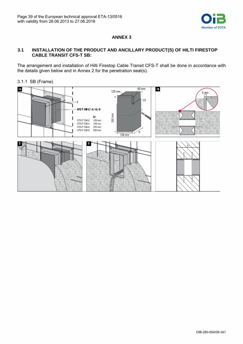
3.1 INSTALLATION OF THE PRODUCT AND ANCILLARY PRODUCT(S) OF HILTI FIRESTOP
CABLE TRANSIT CFS-T SB: The arrangement and installation of Hilti Firestop Cable Transit CFS-T shall be done in accordance with the details given below and in Annex 2 for the penetration seal(s).
3.1.1 SB (Frame)

Member of EOTAINSTITUT FÜR BAUTECHNIKÖSTERREICHISCHES
Page 40 of the European technical approval ETA-13/0516 with validity from 28.06.2013 to 27.06.2018
OIB-280-004/09-341
3.1.2 CFS-T (Transit system)
Exchange cable transit CFS-T

Member of EOTAINSTITUT FÜR BAUTECHNIKÖSTERREICHISCHES
Page 41 of the European technical approval ETA-13/0516 with validity from 28.06.2013 to 27.06.2018
OIB-280-004/09-341
3.2 INSTALLATION OF THE PRODUCT AND ANCILLARY PRODUCT(S) OF HILTI FIRESTOP CABLE TRANSIT CFS-T SBO:
3.2.1 SBO (Frame)
3.2.2 CFS-T (Transit system)
See details on 3.1.2 (CFS-T)

Member of EOTAINSTITUT FÜR BAUTECHNIKÖSTERREICHISCHES
Page 42 of the European technical approval ETA-13/0516 with validity from 28.06.2013 to 27.06.2018
OIB-280-004/09-341
3.3 INSTALLATION OF THE PRODUCT AND ANCILLARY PRODUCT(S) OF HILTI FIRESTOP CABLE TRANSIT CFS-T RR
3.3.1 CFS-T RR (Plug seal and Transit system)

Member of EOTAINSTITUT FÜR BAUTECHNIKÖSTERREICHISCHES
Page 43 of the European technical approval ETA-13/0516 with validity from 28.06.2013 to 27.06.2018
OIB-280-004/09-341
3.4 INSTALLATION OF THE PRODUCT AND ANCILLARY PRODUCT(S) OF HILTI FIRESTOP CABLE TRANSIT CFS-T RR + CFS-T SLF
3.4.1 SLF (Sleeve)
3.4.2 CFS-T RR (Plug seal and Transit system)
See details on 3.3.1 (CFS-T)

Member of EOTAINSTITUT FÜR BAUTECHNIKÖSTERREICHISCHES
Page 44 of the European technical approval ETA-13/0516 with validity from 28.06.2013 to 27.06.2018
OIB-280-004/09-341
3.5 INSTALLATION OF THE PRODUCT AND ANCILLARY PRODUCT(S) OF HILTI FIRESTOP CABLE TRANSIT CFS-T RRS + CFS-T SLF
3.5.1 SLF (Sleeve)
See details on 3.4.1 (CFS-T SLF)
3.5.2 CFS-T RRS (Plug seal)

Member of EOTAINSTITUT FÜR BAUTECHNIKÖSTERREICHISCHES
Page 45 of the European technical approval ETA-13/0516 with validity from 28.06.2013 to 27.06.2018
OIB-280-004/09-341
ANNEX 4
ABBREVIATIONS AND REFERENCE DOCUMENTS
4.1 Abbreviations used in drawings
Abbreviation Description
A1 Hilti Firestop Cable Transit Frame (Sleeve)
A2 Hilti Firestop Cable Transit Modules
A3 Hilti Firestop Cable Transit Wedge
A4 Hilti Firestop Cable Transit Plug Seal
A5 Sealing with Hilti Firestop Acrylic Sealant CFS-S ACR
C1 Cable
C2 Pipe
dC Pipe diameter (nominal outside diameter)
AP1 Cable Insulation
AP2 Pipe Insulation
AP3 Transit Frame Insulation
E Building element (wall, floor)
F Fixing of the frame (sleeve)
s1 Minimum distance between single penetration seals
tC Pipe wall thickness
tD1 Insulation thickness / cable
tD2 Insulation thickness / pipe
tD3 Insulation thickness / transit frame
tE Thickness of the building element
LD1 Length of Cable Insulation
LD2 Length of Pipe Insulation
4.1.2 References to standards mentioned in the ETA:
EN 1026 Windows and doors – Air permeability – Test method
EN 1366-3 Fire resistance tests for service installations - Part 3: Penetration seals
EN 13238 Reaction to fire tests for building products: Conditioning procedures and general rules for selection of substrates
EN 13501 Fire classification of construction products and building elements –
Part 1: Classification using test data from reaction to fire tests
Part 2: Classification using test data from fire resistance tests, excluding ventila-tion services
EN 14303 Thermal insulation products for building equipment and industrial installations - Factory made mineral wool (MW) products – Speci-fication
4.1.3 Other reference documents
EOTA TR 001 Determination of impact resistance of panels and panel assemblies
EOTA TR 024 Characterisation, Aspects of Durability and Factory Production Control for Reac-tive Materials, Components and Products

blank page
Member of EOTAINSTITUT FÜR BAUTECHNIKÖSTERREICHISCHES

blank page
Member of EOTAINSTITUT FÜR BAUTECHNIKÖSTERREICHISCHES

blank page
Member of EOTAINSTITUT FÜR BAUTECHNIKÖSTERREICHISCHES