eurotherm drives · ha387179 issue 10 eurotherm drives 590a series three phase convertors product...
TRANSCRIPT

HA387179 Issue 10
EUROTHERM DRIVES
590A SERIES THREE PHASE CONVERTORS
PRODUCT MANUAL
A WARNING GIVES THE READER INFORMATION WHICH IFDISREGARDED COULD CAUSE INJURY OR DEATH
All rights strictly reserved. No part of this document may be stored in a retrieval system, or transmitted in any form or by any means to persons notemployed by a Eurotherm group company without written permission from Eurotherm Drives Ltd.
Although every effort has been taken to ensure the accuracy of this document it may be necessary, without notice, to make amendments or correctomissions. Eurotherm Drives cannot accept responsibility for damage, injury, or expenses resulting therefrom.

WARRANTY
Eurotherm Drives warrants the goods against defects in design, materials and workmanship for the period of 12months from the date of delivery on the terms detailed in Eurotherm Drives Standard Conditions of Sale
IA058393C.
Eurotherm Drives reserves the right to change the content and product specification without notice.
COPYRIGHT in this document is reserved to Eurotherm Drives Ltd.
INTENDED USERS
This manual is to be made available to all persons who are required to configure, install or service the equipmentdescribed herein or any other associated operation.

WARNINGS AND INSTRUCTIONS
THESE WARNINGS AND INSTRUCTIONS ARE INCLUDED TO ENABLE THE USER TO OBTAIN THEMAXIMUM EFFECTIVITY AND TO ALERT THE USER TO SAFETY ISSUES
NEVER WORK ON THE CONTROLLER, MOTOR, OR AUXILIARY EQUIPMENT WITHOUTFIRST ISOLATING ALL SUPPLIES TO THE SYSTEM.This is a product of the restricted sales distribution class according to iec 61800-3. In a domestic environmentthis product may cause radio interference in which case the user may be required to take adequate measures.This product is designated as ‘professional Equipment’ as defined in EN61000-3-2. Permission of the supplyauthority shall be obtained before connection to the low voltage supply.
APPLICATION AREA: Industrial (non consumer) motor speed control utilising dc shunt machines.
PRODUCT MANUAL: The product manual is to provide a description of how the product works and is not intendedto describe how the apparatus works into which it may be installed.This product manual is to be made available to all persons who are required to: design an application install and serviceor any other associated operation with this product.
APPLICATION ADVICE: Applications advice and training is available from Eurotherm Drives Ltd.
INSTALLATION: Ensure that mechanically secure fixings are used as recommended.
ENSURE THAT THE ENCLOSURE INTO WHICH THIS PRODUCT IS MOUNTED IS SUITABLE FORTHAT ENVIRONMENT (NOTE: THIS PRODUCT MAY BE IP00 OR IP20 AND HENCE REQUIRESFURTHER PROTECTION TO AVOID PERSONAL INJURY).
Ensure that cooling and air flow around the product are as recommended.
Ensure that cables and wire terminations are as recommended and clamped to required torque.
Ensure that the installation and commissioning of this product are carried out by a component person.
Ensure that the product rating is not exceeded.
APPLICATION RISK: The integration of this product into other apparatus or system is not the responsibilityof Eurotherm Drives Ltd as to its applicability, effectivity or safety of operation or of other apparatus or systems.
Where appropriate the user should consider some aspects of the following risk assessment.
RISK ASSESSMENT: Under fault conditions or conditions not intended.
1. The motor speed may be incorrect. }In these situations the users own risk2. The motor speed may be excessive }assessment should provide either3. The direction of rotation may be incorrect. }sufficient guarding to prevent risk of
injury or additional redundant monitoring and safety systems.

4. The motor may be energised unless the installation specifically prevents unexpected or unsequenced energisation ofthe motor.5. Due to the use of electricity in this product, only competent persons may install or service this product and avoidingthe danger of death by electrocution or burning by using established safe working practices.In these situations the users own risk assessment should provide for example lockable isolators to provide safe workingconditions.NOTE: During power loss the product will not operate as specified.
MAINTENANCE: Maintenance and repair should only be performed by competent persons using only therecommended spares (or return to factory for repair). Use of incorrect parts may create a hazard and risk of injury.
WHEN REPLACING A PRODUCT IT IS ESSENTIAL THAT ALL USER DEFINED PARAMETERSTHAT DEFINE THE PRODUCTS OPERATION ARE CORRECTLY INSTALLED BEFORE RETURNINGTO USE. FAILURE TO DO SO MAY CREATE A HAZARD AND RISK OF INJURY.
PACKAGING: The packaging is combustible and if disposed of in this manner incorrectly may lead to the generationof toxic fumes which are lethal.
WEIGHT: Consideration should be given to the weight of the product when handling.
REPAIRS: Repair reports can only be given if sufficient and accurate defect reporting is made by the user.
Remember, the product without the required precautions can represent an electrical hazard and risk of injury, and thatrotating machinery is a mechanical hazard and risk of injury.
PROTECTIVE INSULATION:1. All exposed metal insulation is protected by basic insulation and bonding to earth i.e. Class 1.NOTE: Earth bonding is the responsibility of the installer.2. All signal terminals (terminals 1-39) are SELV, i.e., protected by double insulation (Class 2). The purpose of thisprotection is to allow safe connection to other low voltage equipment and is not designed to allow these terminals to beconnected to any unisolated potential.Ensure all wiring rated for highest system voltage.NOTE: Thermal sensors contained within the motor are to be double insulated.
ENCLOSURE:To maintain compliance with the European Low Voltage Directive Standards VDE 0160(1994)/EN50178(1998) the unit should be mounted inside a suitable control cubicle requiring a tool foropening.
RCDS: Compatible with Type B RCDs only.
CONTROLLER WARRANTY: For further details on Eurotherm Drives Controller Warranty and Repair refer to theStandard Conditions of Sale IA058393C.
EUROTHERM DRIVES RESERVE THE RIGHT TO CHANGE OR ALTER THE SPECIFICATION OF THISPRODUCT WITHOUT NOTICE

TABLE OF CONTENTS
SECTION Page No.
1. INTRODUCTION 1-11.1 545/590A Upgrade 1-11.2 545 to 590A Conversion Chart 1-21.3 590A Introduction 1-4
2. TECHNICAL SPECIFICATIONS 2-12.1 Specification
2.1.1 Control 2-12.1.2 Power 2-2
2.2 Output Ratings 2-32.2.1 Armature Rating 2-32.2.2 Field Rating 2-4
2.3 Mechanical Details 2-4
3. PRODUCT CODE 3-1
4. INSTALLATION & WIRINGINSTRUCTIONS 4-14.1 Installation 4-14.2 Ventilation & Cooling 4-14.3 Basic Wiring Instructions 4-14.4 Notes on Wiring 4-54.5 Additional Installation
Requirements for UL508 4-6Outline & Wiring Diagrams 4-74.6 EMC Installation Guidelines 4-19
5. TERMINAL DESCRIPTIONS 5-15.1 Control Board 5-15.2 Power Board 5-5
6. BLOCK DIAGRAM DESCRIPTION 6-16.1 Power Configuration 6-16.2 The Control Operation 6-16.3 Start and Stop Sequencing 6-4
BLOCK DIAGRAMS
7. BASIC SETTING UP & OPERATINGINSTRUCTIONS 7-17.1 Preset Adjustment Description 7-17.2 Option Switches 7-27.3 Calibration 7-4
7.3.1 Speed Calibration 7-47.3.2 Armature Current Calibration 7-47.3.3 Field Voltage Calibration 7-5
7.4 Before Attempting to ConnectPower 7-5
7.5 Preparation 7-57.6 Checking the Drive & Setting Up 7-67.7 Running Performance
Adjustments 7-7
SECTION Page No.
8. DIAGNOSTIC TEST FACILITIES 8-18.1 Description of Diagnostic Test
Unit 8-18.2 Diagnostic Test Procedure 8-18.3 Connection/Disconnection of
Diagnostic Test Unit 8-18.4 Drive Condition Indicators
Description 8-18.5 Drive Condition Indicators Status
Recognition 8-38.5.1 Stop Condition 8-38.5.2 Start Condition 8-48.5.3 Diagnostic Test Unit -Voltage Measurements 8-7
9. 590 "ALL-IN-ONE" POWER BOARD 9-1Power Circuit Configuration 35/70/110/150/180(4Q)Power Board Layout for 2QPower Board Layout for 4Q590 Power Board (AH385621) 9-6
10 THE EUROPEAN DIRECTIVESAND THE ‘CE’ MARK. 10-110.1 Eurotherm EMC ‘CE’ MarkValidity Chart 10-2Certificates 10-6
11 . SPARES KITS AND SPARE PART IDENTIFICATION LIST 11-1
12. SERVICE INFORMATION 12-1 12.1 Maintenance 12-1 12.2 Customer Assistance Facilities 12-1
Disposal & Packaging 12-2
Power Circuit Configuration 150A (4Q)Power Circuit Configuration 150A (2Q)Power Circuit Configuration 270A (4Q)Power Circuit Configuration 270A (2Q)Power Circuit Configuration 450A (4Q)Power Circuit Configuration 450A (2Q)Power Circuit Configuration 720A (4Q)Power Circuit Configuration 720A (2Q)Layout Ext Stack (4Q)Layout Ext Stack (2Q)Circuit Diagram External Stack ControllerSchematic HB057453C
Modification List

1 - 1
1. INTRODUCTION
1.1 545/590A UPGRADE
The 545 Series product has been applied successfully in a wide variety of applications by machine builders andOEM's.This short note is designed to make a quick comparison between the two products and to show just howconvenient the application of 590A will be.
TERMINALS: Control terminals now numbered 1 - 39. Starting at terminal 4 there is direct exchange between545 and 590A.
A1 - 4A12 - 15B1 - 16 NO POSITIONAL CHANGE OF FUNCTIONB12 - 27C1 - 28C12 - 39
Terminals 1 to 3 are new for the 590A, refer to section 5-1. Power terminals refer to section 5-2.
DIAGNOSTICS: No change of functionality. Existing 5570 diagnostic unit can still be used.NOTE: Logical diagnostics e.g. 5 now +15V is enable
0V is disable.This eases the interpretation of logical diagnostics.
CONDITION INDICATORS (LEDS): Removal of LED4 (trigger fault).
PRESETS: New plug-in preset board with 11 presets. P1 - P10 have identical function as before. P11 allowsadjustment of field supply voltage.
OPTION SWITCHES: Extra options now available on S8 and S9. Direct exchange is:
S1 - S8/1S2 - S8/2 NO CHANGE IN FUNCTIONALITYS3 - S8/3S4 - S8/4
CALIBRATION: Armature current, field voltage of speed feedback are now achieved by switch ableparameters. This allows a very quick and simple commissioning period.
BLOCK DIAGRAM: No change to the functionality, the products are interchangeable.
MECHANICAL PACKAGE: Now uses the common chassis of the 590 product range. Included is;Auxiliary supply voltage 110/240v without tap change.Stack supply voltage 220/500v as standard.Field supply rating 10A and 20A.
ENCLOSURE PROTECTION: IP00 and IP20 versions available.
INTERNATIONAL STANDARDS: UL508
EMC STANDARDS: Refer to Section 10

1 - 2
1.2 545 TO 590A CONVERSION CHART
Control Terminals AFunction 545 590A
LV Signal Common A1 4
Armature Current Compensation A2 5
Setpoint Ramp Reset A3 6
Setpoint Ramp Input A4 7
Setpoint Ramp Output A5 8
Input No 1 A6 9
Input No 2 A7 10
Inverted Sub-Total A8 11
Input No 3 A9 12
Total Setpoint A10 13
+10V Reference A11 14
-10V Reference A12 15
Control Terminals BLV Signal Common B1 16
DC Tachogenerator Input B2 3 (17) *
Current Demand Isolate B3 18
Current Demand Output B4 19
Auxiliary Current Input B5 20
Select Auxiliary Input B6 21
Auxiliary Current Limit (+) B7 22
Main Current Limit B8 23
+10V Reference B9 24
Auxiliary Current Limit (-) B10 25
Buffered Tacho B11 26
Buffered Current B12 27
Note:-1) 545 Terminal B1 has been replaced on the 590A by Terminal 3 for DC Tachogenerators. Terminal 17 can beused if wire lengths are short.2) When using an AC Tachogenerator use terminals 2 & 3 on the 590A.

1 - 3
Control Terminals CLV Power Common C1 28
Thermistor Input C2 29
Auxiliary Enable C3 30
Start Supply C4 31
Enable C5 32
Stop C6 33
Start C7 34
Ready C8 35
Zero Speed Relay Drive C9 36
Drive Operational Relay Drive C10 37
+24V C11 38
External Fault Reset C12 39
Power TerminalsAC Field Supply D1 D1
No Connection D2
No Connection D3
AC Field Supply D4 D2
DC Field +ve D5 D4
No Connection D6
No Connection D7
DC Field -ve D8 D3
Aux Supply Live (L) D9 D8
Aux Supply Neutral (N) D10 D7
Contactor Supply Neutral(N) D11 D6
Contactor Supply Live (L) D12 D5
1 - 4
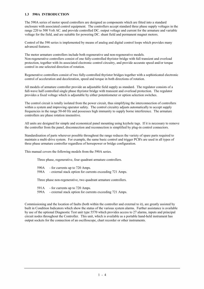
1.3 590A INTRODUCTION
The 590A series of motor speed controllers are designed as components which are fitted into a standardenclosure with associated control equipment. The controllers accept standard three phase supply voltages in therange 220 to 500 Volt AC. and provide controlled DC. output voltage and current for the armature and variablevoltage for the field, and are suitable for powering DC. shunt field and permanent magnet motors.
Control of the 590 series is implemented by means of analog and digital control loops which provides manyadvanced features.
The motor armature controllers include both regenerative and non-regenerative models.Non-regenerative controllers consist of one fully-controlled thyristor bridge with full transient and overloadprotection, together with its associated electronic control circuitry, and provide accurate speed and/or torquecontrol in one selected direction of rotation.
Regenerative controllers consist of two fully-controlled thyristor bridges together with a sophisticated electroniccontrol of acceleration and deceleration, speed and torque in both directions of rotation.
All models of armature controller provide an adjustable field supply as standard. The regulator consists of afull-wave half controlled single phase thyristor bridge with transient and overload protection. The regulatorprovides a fixed voltage which is adjustable by either potentiometer or option selection switches.
The control circuit is totally isolated from the power circuit, thus simplifying the interconnection of controllerswithin a system and improving operator safety. The control circuitry adjusts automatically to accept supplyfrequencies in the range 50-60 Hz and possesses high immunity to supply borne interference. The armaturecontrollers are phase rotation insensitive.
All units are designed for simple and economical panel mounting using keyhole tags. If it is necessary to removethe controller from the panel, disconnection and reconnection is simplified by plug-in control connectors.
Standardisation of parts wherever possible throughout the range reduces the variety of spare parts required tomaintain a multi-drive system. For example, the same basic control and trigger PCB's are used in all types ofthree phase armature controller regardless of horsepower or bridge configuration.
This manual covers the following models from the 590A series.
Three phase, regenerative, four quadrant armature controllers.
590A - for currents up to 720 Amps.598A - external stack option for currents exceeding 721 Amps.
Three phase non-regenerative, two quadrant armature controllers.
591A - for currents up to 720 Amps.599A - external stack option for currents exceeding 721 Amps.
Commissioning and the location of faults (both within the controller and external to it), are greatly assisted bybuilt in Condition Indicators which show the status of the various system alarms. Further assistance is availableby use of the optional Diagnostic Test unit type 5570 which provides access to 27 alarms, inputs and principalcircuit nodes throughout the Controller. This unit, which is available as a portable hand-held instrument hasoutput sockets for the connection of an oscilloscope, chart recorder or other instruments.

2 - 1
2. TECHNICAL SPECIFICATIONS
2.1 SPECIFICATION
2.1.1 Control
Enclosure Rating: IP00, to be built into a suitable cubicle.
Control Circuits: Fully isolated from power circuit. (SELV)
Output Control: Fully controlled 3-phase Thyristor Bridge.Microprocessor implemented phase control over extended firing range.Intended for use on 50Hz or 60Hz supplies with a frequency compliancerange of 45 to 65Hz. Phase control circuits are phase rotation insensitive.
Control Action: Advanced PI with fully adaptive current loops for optimum dynamicperformance.
Speed Control: By analog tach as standard. (AC or DC)
Speed Range: 100 to 1 typical with tach feedback. (DC)
Steady State Accuracy: 0.1% Analog Tach Feedback. (DC)Note:Long term analog accuracy is subject to tach temperature stability
Adjustments: All adjustments are in software can be altered by on-board pushbuttons orvia serial communications. An LCD display provides monitoring ofadjustment parameters and levels in addition to diagnostic facilities.
Protection: Interline device networks.High energy MOV's.Overcurrent (sub cycle over current trip with reset).Overcurrent (inverse time).Field failure.Tach failure.Motor over temperature.Thyristor Stack over temperature (force ventilated units).Zero speed detection.Standstill logic.
Diagnostics: Principal circuit mode and function access.Digital LCD monitoring.LED circuit state indication.LED dynamic trend display.External monitoring/recording/CRT facilities.
Operating TemperatureRange:
0°C +55°CDerate linearly above 35°C for force cooled units.Derate linearly above 45°C for naturally cooled units.
Storage: -25°C +55°CProtect from direct sunlight.Ensure dry, corrosive free environment.
Transport Temperature: -25°C +70°C
Humidity: 85% Relative humidity maximum.Relative humidity is temperature dependent.If the ambient temperature falls the relative humidity will rise and mayultimately cause condensation. This should be avoided.

2 - 2
Climatic Conditions: Class 3k3, as defined by EN50178 (1998).
Atmosphere: Non-flammable, non-condensing.
Pollution Degree:
Installation/OvervoltageCategory :
Electrical Safety Standards:
2
3
UL508, VDE0160 (1994), EN50178 (1998)
EMC Standards: See Section 10.
2.1.2 PowerConfiguration: 590A, 598A* Two Anti-parallel three phase Thyristor bridges.
591A, 599A* One three phase fully controlled Thyristor bridge.* External stack options
Mains Supply: 3-Phase, 50/60 Hz, earth referenced (TN) and non-earth referenced (IT)
Operating SupplyTolerance:
+ 10%
Voltage ranges: 220 to 500Vac - Standard product110 to 220Vac - Special option220 to 660Vac - External stack module (598/599)
Supply Current: (0.9 x Idc) Amps AC rms.
Fan Supply Voltage:(Force Vent Units)
110-120V } +/-10% Single Phase 50/60Hz220-240V } +/-10% Single Phase 50/60Hz
Rating: 110VA when fitted
Contactor Supply: As control voltage110-120V } +/-10% Single Phase 50/60Hz220-240V } +/-10% Single Phase 50/60Hz
Rating: As contactor specification
Control Supply: 110-240V } +/-10% Single Phase 50/60HzRating: 30VANote: No selection required for control supply voltage
Reference Supplies: (For speed and currentsetpoints)
+10V +/- 0.01 at 5mA Max.-10V +/- 0.01 at 5mA Max.
DC Supply: +24V Nominal Internally Regulated.Maximum output capability 6W or 250mA.Auxiliary loading should be totalled before specification to check DC supplyloading if excessive fit a separate power supply.

2 - 3
2.2 OUTPUT RATINGS
2.2.1 ARMATURE RATING
590/1 598/9Output Current Ratings(Armature)1
35A 70A 110A 150A 180A 270A 360A 450A 720A 950A 1100A 1388A 1600A 1800A 2300A 2800A
Nominal Power Rating @460V DC Assuming 95%Motor Efficiency
15KW
(20HP)
30KW
(40HP)
45KW
(60HP)
60KW
(80HP)
75KW
(100HP)
110KW
(150HP)
150KW
(200HP)
190KW
(250HP)
300KW
(400HP)
395KW
(530HP)
455KW
(610HP)
575KW
(770HP)
660KW
(880HP)
745KW
(1000HP)
950KW
(1275HP)
1150KW
(1550HP)
Maximum RatingAmbient 2
45°C 45°C 35°C 35°C 35°C 35°C 35°C 35°C 35°C 35°C 35°C 35°C 35°C 35°C 35°C 35°C
Cooling:Forced(F)/Natural(N) Fan:Integral(I)/Separate(S)
N
-
N
-
F
I
F
I
F
I
F
I
F
I
F
S 3
F
S
F
S
F
S
F
S
F
S
F
S
F
S
F
S
Overload CapacityAvailable (ArmatureCurrent) 4
Y Y Y Y Y Y Y Y N Y Y Y Y Y Y Y
Field Current Rating 10A 10A 10A 10A 10A 10A 20A 20A 20A 30A 30A 30A 30A 30A 30A 30A
Maximum Supply Voltage 500V 500V 500V 500V 500V 500V 500V 500V 500V 660V 660V 660V 660V 660V 550V5 550V8
Maximum Field SupplyVoltage
500V 500V 500V 500V 500V 500V 500V 500V 500V 500V 500V 500V 500V 500V 500V 500V
Power Loss 105W 210W 330W 450W 540W 710W 1080W 1350W 2160W 2850W 3300W 4164W 4800W 5400W 6900W 8400W
Installation Drawing HG: 055805 055805 055806 055806 386968 055807 057208 057209 0574496 0578297
0578297
0578297
0578297 0578297
0578297
0578297
1 Altitude derating, nominal sea level to 500 metres, derate above 500 metres at 1% per 200 metres up to maximum of 5,000 metres.2 Derate linearly at 1% per degree centigrade for temperature exceeding the maximum rating ambient. Maximum operating ambient is 55°C.3 A lower current version limited to 360Amps is available with an integral fan (HG057208).4 The standard overload capacity available is 200% for 10 seconds, 150% for 30 seconds. The 720 Amp Chassis has no overload capacity at maximum current, whereas at output currents lessthan 650 Amps overload capacity is as normal.5 External Stack assemblies at 660V are not available above 2000 Amps without reference to Eurotherm Drives Internal Sales Department.6 For Installation Drawings for 720A Stock Assembly see: HG049669 Standard Mounting / HG054248 Bracket Mounting.7 Installation Drawings for External Stack Thyristor assemblies available on application to Eurotherm Drives Engineering Department.

2 - 4
2.2.2 FIELD RATINGOutput current ratings:590A/0350-590A/2700 } i.e. from 35A build to 270A build 10A591A/0350-590A/2700 }590A/4500 - 590A/7200 } i.e. from 450A build to 720A build 20A591A/4500 - 591A/7200 }
598A } i.e. external stack builds 30A599A }
2.3 MECHANICAL DETAILSGENERAL1. All controllers should be mounted vertically in the cubicle to allow good air flow across the cooling fin.
Naturally cooled units should be given special consideration to permit cool air entry into and hot air exitbelow and above the controller.
2. If the enclosure is totally enclosed the metal surface dissipates 50 watt sq.metre for a 10°C temperature rise.
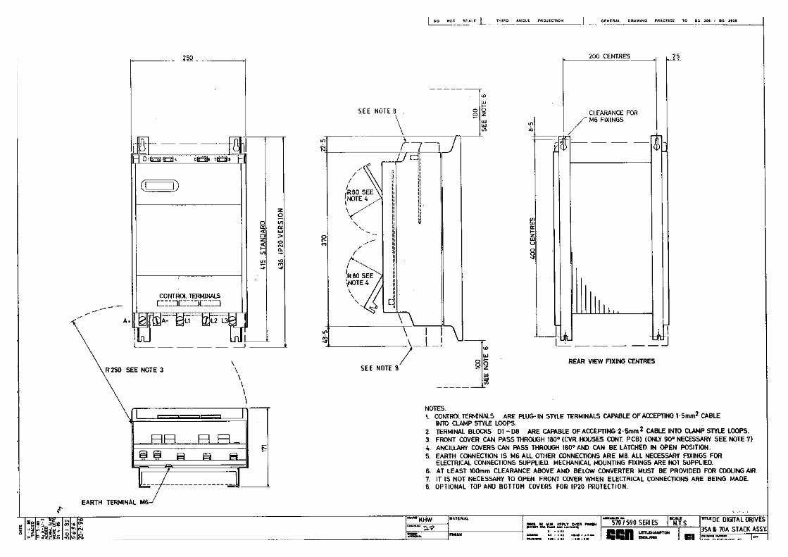
590A AND 591A CONVERTORS
RATING UP TO 180A:75KW (100HP)Mounting Centres: Vertical - 400mm (15.75")
Horizontal - 200mm (7.87")
Rating up to 70A 30KW (40HP)
Rating up to 150A 60KW (80HP)
Rating up to 180A 75KW (100HP)
Overall Width: 250mm (9.8") 250mm (9.8") 250mm (9.8")Overall Height: 415mm (16.5") 440mm (17.3") 500mm (19.7")Overall Depth: 170mm (6.7") 170mm (6.7") 170mm (6.7")Weight: 10Kg-14Kg
(22lbs-30lbs)15Kg(33.2lbs)
17Kg(37.5lbs)
Nominal BlowerThroughput:
100m3/Hour 300m3/Hour
Minimum AirflowClearance:
100mm (4") above100mm (4") below
100mm (4") above100mm (4") below
100mm (4") above100mm (4") below
Control Terminations: Plug-on connectors with retaining catches.Power Terminations: Bus-bars with 8mm screws and captive nuts.
Earth termination 6mm screw and captive nut.Access: Hinge-up cover for control circuit terminals and Diagnostics socket.
Hinge-out Control Printed Board with its own independent cover.
RATING UP TO 270A:110KW (150HP)Mounting Centres: Vertical - 400mm (15.75")
Horizontal - 200mm (7.87")Overall Width: 250mm (9.8")Overall Height: 500mm (19.7")Overall Depth: 210mm (8.3")Weight: 20Kg (44lbs)Minimum AirflowClearance:
150mm (6") above and 100mm (4") below
Nominal BlowerThroughput:
350m3/Hour
Control Terminations: Plug-on connectors with retaining catches.Power Terminations: L1/L2/L3 Bus-bars with 8mm bolts and Belville washers.
A+/A- Bus-bars with 8mm nuts, bolts and Belville washers. Earth termination 6mm screw and captive nut.
Access: Hinge-up cover for control circuit terminals and Diagnostics socket.Hinge-out Control Printed Board with its own independent cover.

2 - 5
RATING UP TO 450A:190KW (250HP)Mounting Centres: Vertical - 600mm (23.6")
Horizontal - 200mm (7.87")Overall Width: 250mm (8.75mm") (322mm (12.7") over dc terminals)Overall Height: 705mm (27.75") Integral Fan
675mm (26.6") Roof FanOverall Depth: 252mm (9.9")Weight: 30Kg (66lbs)Minimum AirflowClearance:
100mm (4") below150mm (6") above100mm (4") below duct for roof fan
} Integral Fan}} Roof Fan
Nominal BlowerThroughput:
490m3/Hour Integral Fan
Control Terminations: Plug-on connectors with retaining catches.Power Terminations: L1/L2/L3 Bus-bars with 12mm bolts and Belville washers.
A+/A- Bus-bars with 10mm nuts, bolts and Belville washers. Earth termination 10mm stud and Belville washer.
Access: Hinge-up cover for control circuit terminals and Diagnostic Socket.Hinge-out Control Printed Board with its own independent cover.
RATING UP TO 720A:300KW (400HP)Mounting Centres: (see drawing)Overall Width: 319mm (12.6") (362mm over dc terminals)Overall Height: 920mm (36.2") (Module only not including fan equipment and ducting).Overall Depth: 194mm (7.6") to mounting plane.
140mm (5.5") behind mounting plane.Weight: 65Kg (143lbs)Minimum AirflowClearance:
See installation drawings HG049669F and HG045248F.
Nominal BlowerThroughput:
1000m3/Hour @ 80 mbar for rated output.
Control Terminations: Plug-on connectors with retaining catches.Power Terminations: L1/L2/L3 Bus-bars with 14 mm bolts and Belville washers.
A+/A- Bus-bars with 10mm nuts bolts and Belville washers. Earth termination 8mm bolts and Belville washers in 2 alternate positions.
Access: Hinge-up cover for control circuit terminals and Diagnostic Socket.Hinge-out Control Printed Board with its own independent cover.
TERMINALS - Tightening TorqueThe following table should be referred to when making connections to the controller.
Power Board Terminal Blocks 4 lb-in (0.45Nm)Control Board Terminal Blocks 5 - 7 lb-in (0.56 - 0.79Nm)
Product Current Rating (A) Terminations Maximum Tightening Torque0 - 180A L1, L2, L3, A+, A-
GROUND M8 12.2lb.ft.* 16.5Nm*M6 5.0lb.ft 6.8Nm
181A - 270A L1, L2, L3, A+, A-GROUND
M8 12.2lb.ft. 16.5NmM6 5.0lb.ft. 6.8Nm
271A - 450A L1, L2, L3A+, A-GROUND
M12 42.2lb.ft. 57.2NmM10 24.2lb.ft. 32.8NmM10 24.2lb.ft. 32.8Nm
451A - 720A L1, L2, L3A+, A-GROUND
M14 67.1lb.ft. 91.0NmM10 24.2lb.ft. 32.8Nm
M8 12.2lb.ft. 16.5Nm
Note:* M8 CHEESEHEAD SCREW, TIGHTENING TORQUE 8.1lb.ft. 11Nm

3 - 1
3. PRODUCT CODE
590A AND 591A THREE PHASE CONVERTERSAll members of the three phase product range can be fully specified using a digit numerical order code.
Block No No of Digits Function1 4 Basic Product2 4 Output Current3 1 Supply Voltage (Power)4 1 Supply Voltage (Auxiliary)5 2 Special Builds
The 5 blocks are defined as follows:Block 1: 4 Digits identifying the basic product.590A: 3 phase, 4 Quadrant (regenerative) convertor 35A to 720A.591A: 3 phase, 2 Quadrant (non-regenerative) convertor 35A to 720A.598A: 3 phase, 4 Quadrant (regenerative) external stack controller.599A: 3 phase, 2 Quadrant (non-regenerative) external stack controller.
Block 2: 4 digits identifying the DC output current rating.590A/591A: The digits in this block represent a number between 000.0 and 999.9. To form the code from
the numbers, the decimal point is suppressed and leading zeros are added where necessary.Examples: 234.5 Amps Code 2345Conversely: Code 1234 123.4 Amps
598A/599A: 5 digits identifying the DC output current rating.The digits in this block represent a number between 0000.0 and 2800.0. To form a code fromthe numbers, the decimal point is suppressed and leading zeros are added where necessaryExamples: 1250 Amps Code 12500Conversely: Code 11250 1125 Amps
Block 3: 1 Digit identifying the nominal 3 Phase AC power, supply Voltage.
0 110V1 115V2 208V3 220V4 240V5 380V6 415V7 440V8 460V9 480VA 500VB 550V 598A/599A External Stacks onlyC 600V 598A/599A External Stacks onlyD 660V 598A/599A External Stacks only
Block 4: 1 Digit identifying the auxiliary AC control supply Voltage.0 110V1 115V23 220V4 240V
Block 5: 2001 to 99
Digits identifying special optionNo special optionsDocumented special options

4 - 1
4. BASIC INSTALLATION AND WIRING INSTRUCTIONS
4.1 INSTALLATION
The 590A series motor speed controllers are designed as components which are to be fitted with other controlequipment in a suitable enclosure. The control units are all designed to mount directly onto a flat surface. Theyshould be fastened by means of bolts or screws through the fixing points at each corner. These points are in theform of keyholes and slots to simplify fastening or removal.
Please see the relevant installation drawings in this manual for overall dimensions and positions of fixing holesand to identify size of holes and fixings.Note: The fixing centres of 590A series controllers are designed to allow use of 100mm grid fixing.
4.2 VENTILATION AND COOLING
In normal operation the drive unit needs to dissipate heat and must, therefore, be mounted to permit the free flowof cool air vertically through the circuit board area, over the fuses and across the heat sink area at the back.The normal maximum ambient operating temperatures are:-
Naturally ventilated unit: 45°C (113°F)Fan-force cooled units: 35°C (95°F)
For operation above these limits derating of the controller may be necessary, refer to the electrical specificationwithin this manual or the engineering department of Eurotherm Drives.
Care should be taken to ensure that the mounting surface is also cool and that any heat generated by the adjacentequipment is not transmitted to the drive unit.As a general rule allow about (150mm) 6" of clear space above and below the drive for free air flow.
4.3 BASIC WIRING INSTRUCTIONS
The following set of instructions is a description of the wiring requirements of a 590A series controllerconfigured in the General Purpose mode for operation as a basic speed controller. The complexity of connectionwhen configured in any other mode for specific drive applications, precludes the inclusion of diagrams showingall wiring options. Special options are usually part of a customer specific system and connection diagrams ofthese controllers from part of the information provided for the system.Information showing the connections required to provide a basic speed control system when using a 590 seriescontroller are given in wiring diagram HJ 387211.
1. Power cables must have a minimum rating of 1.1 x full load current. (1.25 x FLC when required tocomply with UL requirements).
2. Control wiring must have a minimum cross-sectioned area of 0.75mm2 (square millimetre).
3. All incoming main ac power supply connections must be protected with High Speed semiconductorfuses. The rating of these fuses being as shown below:-
EUROPEAN STYLE FUSES
PRODUCT CODE BS88 TYPE FUSE DIN TYPE FUSE THYRISTOR A2TBLOCK 2 FUSE
RATINGPART
NUMBERFUSE
RATINGPART
NUMBER@ 125°°°°C JUNCTION
TEMPERATURE0010 to 0350 35A CH110353 40A CH570044 800 A2T0351 to 0700 75A CH120753 80A CH570084 8,000 A2T0701 to 1100 110A CH120114 160A CH580164 8,000 A2T1101 to 1800 150A CH120154 200A CH580025 15,000 A2T1801 to 2700 300A CH130035 550A CH590554 125,000 A2T2701 to 4500 ------- -------------- 700A CH590075 320,000 A2T4501 to 7200 ------- -------------- 800A CH590085 500,000 A2T

4 - 2
4. Motor overload protection is provided in the controller by means of the thermal device in the motorwinding. This protection cannot be evaluated by UL hence it is the responsibility of the installer and/orthe local inspector to determine whether the overload protection is in compliance with the NationalElectric Code or Local Code requirements
5. A substantial ground or earth connection (Protective Earth) should be made to the earth terminal of the590A drive, the protective earth connection being indicated by the IEC grounding symbol (as defined inIEC 417 symbol 5019) . On the 720/800A chassis two M8 terminals are provided BOTH MUSTBE connected to protective earth/ground.
6. The motor protective earth/ground connection should be run in parallel with the motor supplyconductors ideally inside the same conduit/screen/armour and be connected near to the drive to aseparate independent protective earth/ground star point. DO NOT RUN THE MOTOR PROTECTIVEEARTH/GROUND VIA THE 590 CONTROLLER EARTH/GROUND TERMINAL. CONNECTDIRECTLY TO ENCLOSURE EARTH/GROUND.
7. A 3 phase contactor should be connected in the main ac power supply connections with a rating suitablefor the controller concerned. The contactor does not switch current and is primarily for isolation andsequencing of the power bridge. The main contactor must be energised directly from the controller byconnecting the coil to terminals D5 (Line) and D6 (Neutral). No additional series contacts or switchesare permitted since they will interfere with the sequencing of the controller and cause unreliability andpossible failure.Notes:1 If the 3-phase contactor has a coil with an inrush greater than 3 Amps a slave relay must be
used do drive the contactor2. The contactor and slave relay (if required) must have coil voltages compatible with the
controller auxiliary supply voltage.3. A dc contactor can be used but the sequencing must be adjusted to accommodate its use, an
auxiliary normally open volt-free contact of the contactor must be connected in series with the"enable" input C5 to disable the drive unit after the contactor is closed.
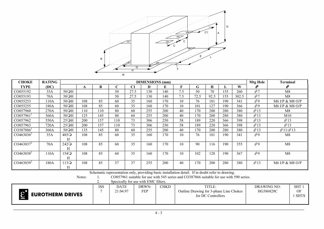
8 A 3 phase ac line reactor should be fitted in series with the incoming main 3 phase ac power supply.(Eurotherm Drives stock a series of reactors suitable for this duty, mechanically designed to connectdirectly to the controller ac supply terminals). The reactor should be connected between the controllerand the ac contactor for optimum protection and safety. Refer to HG386828C for selection of AC LINEREACTOR.
9. EMC filters should only be fitted on the mains side of the contactor.
10. The auxiliary or control supply (single phase 50/60Hz) should be connected to terminals D8 (Line) andD7 (Neutral) with suitable external fuse protection. The steady state current absorbed by the controlleris nominal, the external fuse is determined chiefly by considering the contactor holding VA and thecontroller cooling fans.Notes: 1. Auxiliary supply range 110V-240V. No tapping required when switch mode power supply is
used. 2. The auxiliary supply must be connected directly to the incoming supply, no series switches or
contacts are permitted without consultation with Eurotherm Drives Engineering Department.
11. Connect the motor field (-) to terminal D3 and field (+) to terminal D4. If the motor has no fieldconnections, a permanent magnet motor, or if the field is derived externally, it will be necessary tooverride the field fail detector by ensuring that switch S9/5 is on.
4 - 3
WH
G
B
CC
C1 A
D
E L
F
CHOKE RATING DIMENSIONS (mm) Mtg Hole TerminalTYPE (DC) A B C C1 D E F G H L W ���� ����
CO055192 35A 50�H 50 27.5 130 140 7.5 50 70 155 260 �7 M8CO055193 70A 50�H 50 27.5 130 140 7.5 72.5 92.5 155 302.5 �7 M8CO055253 110A 50�H 108 85 60 35 160 170 10 76 101 190 341 �9 M6 I/P & M8 O/PCO055255 180A 50�H 108 85 60 35 160 170 10 101 127 190 366 �9 M6 I/P & M8 O/PCO057960 270A 50�H 110 110 80 60 255 200 40 170 200 280 380 �13 M8CO0579611 360A 50�H 125 145 80 60 255 200 40 170 200 280 380 �13 M10CO057962 550A 25�H 200 157 110 73 306 250 58 189 220 366 398 �13 �13CO057963 720A 25�H 200 157 110 73 306 250 58 189 220 366 398 �13 �13CO3878861 360A 50�H 135 145 80 60 255 200 40 170 200 280 380 �13 �11/�13CO4630362 35A 485�
H108 85 60 35 160 170 10 76 101 190 341 �9 M8
CO4630372 70A 242�H
108 85 60 35 160 170 10 90 116 190 355 �9 M8
CO4630382 110A 154�H
108 85 60 35 160 170 10 102 128 190 367 �9 M8
CO4630392 180A 113�H
108 85 57 37 255 200 40 170 200 280 380 �13 M6 I/P & M8 O/P
Schematic representation only, providing basic installation detail. If in doubt refer to drawing.Notes: 1. CO057961 suitable for use with 545 series and CO387866 suitable for use with 590 series.
2. Specically for use with EMC filters.
EUROTHERM DRIVES
ISS7
DATE21.04.97
DRWN:FEP
CHKD TITLE:Outline Drawing for 3-phase Line Chokes
for DC Controllers
DRAWING NO:HG386828C
SHT 1OF
1 SHTS

4 - 4
12. If an external field supply is required to the controller for application reasons this supply should beconnected to terminals D1 and D2. The magnitude of this voltage is determined by the desired fieldvoltage. (For more information on this subject see terminal block descriptions). The supply must beprotected externally with suitable fuses. The supply must always be derived from the Red andYellow phases of the main power supply with Red phase connected to terminal D1 and Yellowphase to terminal D2.Note: It is important that the connection of the external field supply is consistent when using anexternally supplied field regulator. To ensure correct operation Red phase and Yellow phase arerequired to be those phases connected to terminals L1 and L2 respectively of the main powerconnections.
It is relatively simple to change the controller from an internal to an external field type.
The red wire of the field wire loom sitting on the RED phase internal terminal (F1) must be moved tothe FE-R terminal adjacent to D1 and the yellow wire of the YELLOW phase internal terminal (F1)must be moved to the FE-Y terminal adjacent to D2.
13. The main ac power is connected to bus bar terminals L1, L2 and L3, there is no specific phaseconnection to these three terminals as the controller is phase rotation independent. The connectionsmust be made via the correct high speed semiconductor fuses, the main contactor and the ac linereactor.
14. The motor armature should be connected to bus bar terminals A+ and A-. If a dc contactor is used thepoles should be interposed between the controller terminals and the motor terminals.Note: When the controller is operating in a regenerative mode for extended periods acting as a loadgenerator for another machine it is advisable to fit additional protection in the armature circuit. A dcfuse or a high speed circuit breaker will provide this protection, if in doubt consult the EurothermDrives Engineering Department.
15. For normal operation the speed demand signal is connected to the "Setpoint Ramp Input" terminal 7.This input is scaled so that:-
+10V input = maximum forward speed demand (+100%)-10V input = maximum reverse speed demand (-100%)
The speed demand signal can be generated by connecting the two ends of an external 10Kpotentiometer to the +10V reference terminal 14 and -10V reference terminal 15, the wiper of thepotentiometer being connected to the "setpoint ramp input" as the speed reference.For non-reversing applications and 2 quadrant controller (591,etc) the speed demand only needs tooperate between 0V and +10V, the anti-clockwise end of the potentiometer should then be connected tosignal ground terminal 4. Three other terminals are provided as speed setpoint inputs: terminal 9Setpoint No1, .terminal 10,Setpoint No.2 both giving direct speed demand by-passing the setpoint rampgenerator, terminal 12, Setpoint No. 3, provides a direct inverting speed demand which bypasses thesetpoint generator.
16. The controller has the capability of operating with two forms of feedback:-i) Analog DC tachii) Analog AC tach
USE OF AC TACH IS RESTRICTED TO 2 QUADRANT 591A ONLY.
If an analog DC tach is required this should be connected with its negative terminal connected toterminal 4 and its positive terminal connected to terminal 3. It is important that this signal cable is ascreened twisted pair cable throughout its entire length. The screen should be grounded or earthed onlyat one end, any other grounding arrangement may cause problems.If an AC tach is used it should be connected to terminals 1 and 2. It is important that this signal cable isa screened twisted repair throughout its entire length. The screen should be grounded or earthed only atone end, any other grounding arrangements may cause problems.
Note: Selection of AC tach or DC tach is made via option switch S 1, located on the control board.

4 - 5
17. The Main Current Limit is adjustable by means of potentiometer P7 (under the front cover of thecontroller). For normal operation the Main Current Limit terminal 23 should be connected to the +10VReference terminal 24. This gives adjustment on P7 of 0 to 200% full load current. If external controlof Main Current Limit is required, this is achieved by applying a variable voltage to terminal 23 so that0 to 10 Volts gives 0 to 200% F.L.C. (when potentiometer P7 turned fully clockwise).
18. If the motor is fitted with over-temperature sensing devices such as thermostats, microtherms or PTCthermistors these should be connected between terminals 28 and 29. If more than one temperaturesensing device is fitted they should be connected in series, if none are fitted terminals 28 and 29 mustbe linked to allow the drive to run. Thermistors must have a working resistance of 200 Ohms or lessrising 2000 Ohms at over-temperature.
19. The Enable and Auxiliary Enable terminals 32 and 30 must be connected to 31 in order that the drivemay run. However, external normally closed interlock contacts may be connected in series with 30.Interruption of the supply to terminal 30 will disable the drive and the Ready and Drive Operationaloutputs.Note: The Thermistor/microtherm and Field failure alarms normally disable the drive only while a faultexists; if the fault clears, because the motor cools down for example, the motor will restartautomatically. However, these alarms can be made to latch the drive in the disabled stated indefinitelyby connecting 30 to 37 instead of 31 (any external interlock contacts connected in the 30 to 37 link willalso be latched in this manner). In this mode a Thermistor/microtherm, Field failure or externalinterlock alarm condition can only be cleared, and the motor restarted, by removal of the start i.e. stopand the reapplication of start
To provide the latching of the health condition without requiring the use of external wiring, switchS8/5 can be used
20. Stop/Start control is normally provided either from two momentary contacts or from a single holdingcontact.
i) Momentary contacts:-
Connect normally closed STOP contact between terminals 31 and 33.Connect normally open START contact between terminals 33 and 34.
Note: Additional STOP push-buttons should have normally closed contacts and should be wired inseries with main STOP push-buttons between terminals 31 and 33.
ii) Single holding contact:-
Connect between terminals 31 and 34.Open contact to STOP.Close contact to START.
4.4 NOTES ON WIRING
1. Indicator lamps, annuniciators, etc, for "Drive On" condition should be switched by an auxiliarycontactor of the main contactor, not by the controller auxiliary relay.
2. All connections made to terminal blocks must be isolated signal voltages.
3. To avoid damaging the drive NEVER carry out high voltage resistance or dielectric strength testswithout first completely disconnecting the drive from the circuit being tested.
4. If in doubt about the connection of the dc motor to the controller check with Eurotherm DrivesEngineering Department.
4 - 6
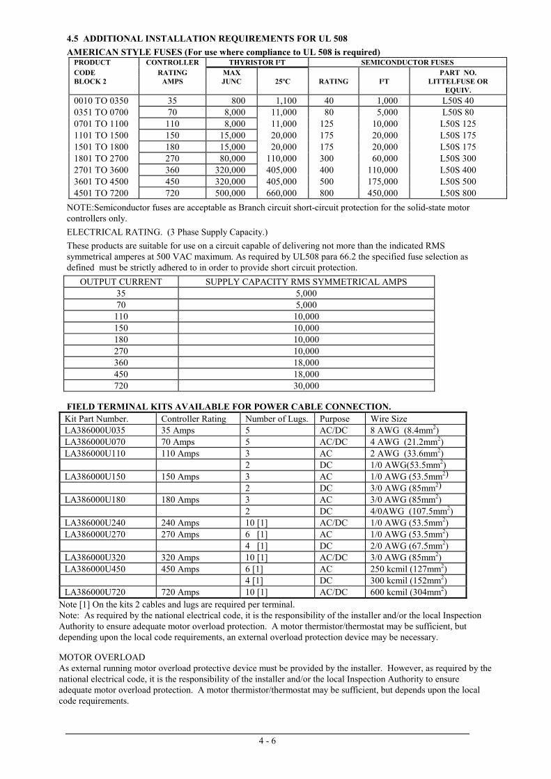
4.5 ADDITIONAL INSTALLATION REQUIREMENTS FOR UL 508AMERICAN STYLE FUSES (For use where compliance to UL 508 is required)
PRODUCT CONTROLLER THYRISTOR I²T SEMICONDUCTOR FUSESCODE RATING MAX PART NO.BLOCK 2 AMPS JUNC 25ºC RATING I²T LITTELFUSE OR
EQUIV.0010 TO 0350 35 800 1,100 40 1,000 L50S 400351 TO 0700 70 8,000 11,000 80 5,000 L50S 800701 TO 1100 110 8,000 11,000 125 10,000 L50S 1251101 TO 1500 150 15,000 20,000 175 20,000 L50S 1751501 TO 1800 180 15,000 20,000 175 20,000 L50S 1751801 TO 2700 270 80,000 110,000 300 60,000 L50S 3002701 TO 3600 360 320,000 405,000 400 110,000 L50S 4003601 TO 4500 450 320,000 405,000 500 175,000 L50S 5004501 TO 7200 720 500,000 660,000 800 450,000 L50S 800
NOTE:Semiconductor fuses are acceptable as Branch circuit short-circuit protection for the solid-state motorcontrollers only.ELECTRICAL RATING. (3 Phase Supply Capacity.)These products are suitable for use on a circuit capable of delivering not more than the indicated RMSsymmetrical amperes at 500 VAC maximum. As required by UL508 para 66.2 the specified fuse selection asdefined must be strictly adhered to in order to provide short circuit protection.
OUTPUT CURRENT SUPPLY CAPACITY RMS SYMMETRICAL AMPS35 5,00070 5,000
110 10,000150 10,000180 10,000270 10,000360 18,000450 18,000720 30,000
FIELD TERMINAL KITS AVAILABLE FOR POWER CABLE CONNECTION.Kit Part Number. Controller Rating Number of Lugs. Purpose Wire SizeLA386000U035 35 Amps 5 AC/DC 8 AWG (8.4mm2)LA386000U070 70 Amps 5 AC/DC 4 AWG (21.2mm2)LA386000U110 110 Amps 3 AC 2 AWG (33.6mm2)
2 DC 1/0 AWG(53.5mm2)LA386000U150 150 Amps 3 AC 1/0 AWG (53.5mm2)
2 DC 3/0 AWG (85mm2)LA386000U180 180 Amps 3 AC 3/0 AWG (85mm2)
2 DC 4/0AWG (107.5mm2)LA386000U240 240 Amps 10 [1] AC/DC 1/0 AWG (53.5mm2)LA386000U270 270 Amps 6 [1] AC 1/0 AWG (53.5mm2)
4 [1] DC 2/0 AWG (67.5mm2)LA386000U320 320 Amps 10 [1] AC/DC 3/0 AWG (85mm2)LA386000U450 450 Amps 6 [1] AC 250 kcmil (127mm2)
4 [1] DC 300 kcmil (152mm2)LA386000U720 720 Amps 10 [1] AC/DC 600 kcmil (304mm2)
Note [1] On the kits 2 cables and lugs are required per terminal.Note: As required by the national electrical code, it is the responsibility of the installer and/or the local InspectionAuthority to ensure adequate motor overload protection. A motor thermistor/thermostat may be sufficient, butdepending upon the local code requirements, an external overload protection device may be necessary.
MOTOR OVERLOADAs external running motor overload protective device must be provided by the installer. However, as required by thenational electrical code, it is the responsibility of the installer and/or the local Inspection Authority to ensureadequate motor overload protection. A motor thermistor/thermostat may be sufficient, but depends upon the localcode requirements.


4 - 19
4.6 EMC INSTALLATION GUIDELINES
INTRODUCTIONThis section provides installation guidelines for drive modules and systems to maximise their ‘Electro Magneticcompatibility’ (EMC) in their intended operating environment. All installers must read this section and apply the advicewhich is relevant to their application. Pass on this information to others as is appropriate.
All power drive systems have the potential to produce electrical emissions, both radiated and conducted back into the ACsupply. This is due to the inherent operation of all drives by switching large voltages and currents rapidly in order tocontrol the motor. Because the drives internal control electronics operates continuously in very close proximity to theelectrically noisy power switching elements, drives are inherently immune to any additional external electrical noise.
Great care has been taken in the design and selection of suitable EMC filters to provide the correct level of interfacesuppression, ease of installation and to ensure that electrical safety is not compromised. The EMC performance can only beguaranteed to be within the limits specified when the 590 drive modules are installed together with the recommended EMCfilters and line chokes in accordance with the following instructions.
The subject of EMC is explored in more detail in a separate Eurotherm Application Manual entitled “EMC InstallationGuidelines for Modules and Systems”, part number HA388879, available from your local Eurotherm office.
EMC FILTERS TO REDUCE LINE CONDUCTED NOISEAn EMC supply filter may be used with each 590 drive module to reduce the line conducted noise. For higher currentproduct 300 amp filter modules will be used in parallel. The 590 range of industrial DC drives can be supplied with filtersto meet the ‘industrial’ Class A EMC environment when used with the specified 2% minimum line chokes as listed below.All ac supply filters should only be fitted on the mains side on the contactor.
Table A - AC Supply Filter and Line Choke Part Numbers for Conformance with EN55011 Class A.
EurothermProduct
ArmatureCurrent Rating
Eurotherm Filter PartNo.
Total FilterWatt Loss
Eurotherm EMCLine Reactor
590 / A, D, L 35 Amp 1 off CO388965U035 25W CO463036
“ 70 Amp 1 off CO388965U110 75W CO463037
“ 110 Amp 1 off CO388965U110 75W CO463038
“ 150, 180 Amps 1 off CO388965U180 158W CO463039
“ 270 Amps 1 off CO389456 50W CO057960
“ 360 Amps 1 off CO389456 50W CO057961
“ 450 Amps 2 off CO389456 100W CO057962
“ 720 Amps 2 off CO389456 100W CO057963
“ 800 Amps 3 off CO389456 100W CO057963
Table B - AC Supply Filter Part Numbers for ‘non CE marked’ Product.
EurothermProduct
ArmatureCurrent Rating
Eurotherm Filter PartNo.
Total FilterWatt Loss
Line ChokeRequirement
590 / A, D, L 950, 1100 Amps 3 off CO389456 150W
“ 1388 Amps 4 off CO389456 200W 2 % minimum,
“ 1600, 1800 Amps 5 off CO389456 250W refer to
“ 2300 Amp 7 off CO389456 350W Eurotherm Drives
“ 2800 Amp 8 off CO389456 400W
4 - 20
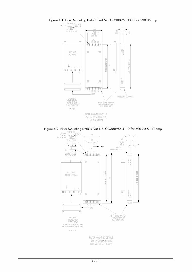
Figure 4.1 Filter Mounting Details Part No. CO388965U035 for 590 35amp
Figure 4.2 Filter Mounting Details Part No. CO388965U110 for 590 70 & 110amp

4 - 21
Figure 4.3 Filter Mounting Details Part No. CO388965U180 for 590 360 amp
Figure 4.4 Filter Mounting Details Part No. CO389456 for 590 270 amp

4 - 22
Figure 4.5 Filter Mounting Details using 2x Part No. CO389456 for 590 360amp
These filters and chokes may be mounted to the left, right, above, below or spaced behind the product, but can be mountedin two orientations i) flat against the wall or ii) projecting out from the wall, mounting arrangements are shown in figures4.1 - 4.5. When filters CO389456 are mounted in parallel, they should be spaced 40mm apart for ventilation.
The CO389456 filter flying leads may reach 100oC under normal operating conditions and should be separated by at leastone cable diameter and be adequately ventilated. Never bunch the leads together.
Note: For 590 drives the specified EMC line choke in table A or B must still be used between the 590 and its filter.This is to ensure reliability of both the filter and the drive.
The EMC filter and line choke should be mounted as close to the 590 drive module as possible. The connection betweenthe 590, choke and filter must always be as short as possible taking care not to obstruct any ventilation spacing and besegregated from all other cables. If this cable/busbar exceeds 0.6m in length then it must be replaced with ascreened/armoured cable, with the screen/armour earthed at both the filter, choke and inverter ends with large-area contactsurfaces, preferably with metal cable glands. The routing of the cables/busbars between the filter, choke and drive moduleshould be chosen to ensure their close proximity. Failure to achieve this will result in increased conducted emissions. Theconnection between the 590 drive module and the motor must be installed away from all other cables or wires. Ideally thefilter and choke will be mounted onto the same metallic panel as the drive. The RF connection between the drive, filter andpanel should be enhanced as follows:-
- Remove any paint/insulation between the mounting points of the EMC filter, choke and 590 drive moduleand panel.
- Liberally apply petroleum jelly over the mounting points and securing threads to prevent corrosion.alternatively conducting paint could be used on mounting panels.
- If the proceeding is not possible, then the RF earth bond between the filter and 590 drive module isusefully improved by making an additional RF earth connection using wire braid of at least 10 mm2 crosssectional area (due to skin effect).
NOTE: Metal surfaces such as eloxized or yellow chromed e.g. with cable mounting or 35 mm DIN rails, screwsand bolts have a high RF impedance which can be very detrimental for EMC performance.
A low RF impedance path must be provided between the motor frame and back panel on which the drive, choke and EMCfilters are mounted. This low impedance RF path should follow the path of the motor cables in order to minimise the looparea. Failure to do so will result in increased conducted emissions.
4 - 23
This will normally be achieved by:-
1. Bonding the armour of the motor supply cables at one end to the motor frame and at the other to thecubicle back panel. Ideally 360o bonding is required, which can be achieved with cable glands.
2. Ensuring that conduit containing the motor supply cables are bonded together using braid. The conduitshall also be bonded to the motor frame and the cubicle back panel.
Care should be taken to ensure that the protective earth (PE) conductor exiting from the filter is connected to the protectiveearth connection of the choke and 590 drive module. Any additional RF earth such as a cable screen is not a protectiveearth. The EMC filter must be permanently earthed to prevent the risk of electric shock under abnormal operatinginstances (such as the loss of one phase of the AC supply). Permanent earthing can be achieved by either:
- Using a copper protective earth conductor of at least 10 mm2 or- Installing a second conductor in parallel connection with the protective conductor to a separate protective
earth terminal.
Each conductor shall on its own meet the requirements for a protective earth conductor. On all recommended EMC filterstwo protective earth connections are provided for permanent earthing.
The recommended EMC filters are designed to operate from normal three-phases supplies which are balanced with respectto earth (earth referenced supplies). This minimises the earth leakage current due to the filter capacitors between phase andearth. On some specific customer sites the supply may not be balanced with respect to earth (non-earth referenced supplies).The earth leakage currents would increase and interfere with the operation of any earth-fault monitoring equipment. Inaddition the EMC performance of the filter will be degraded. Eurotherm Drives do not recommend the use of AC supplyfilters on non earth-referenced supplies.
As with all power electronic drives the conducted emissions increase with motor cable length. EMC conformance tothe stringent limits is only guaranteed up to a cable length of 50. This length can be increased. Refer to EurothermDrives for more information.
If one EMC filter is to be used in an enclosure, then this filter should be mounted as close to the incoming AC supply tothe enclosure as possible.
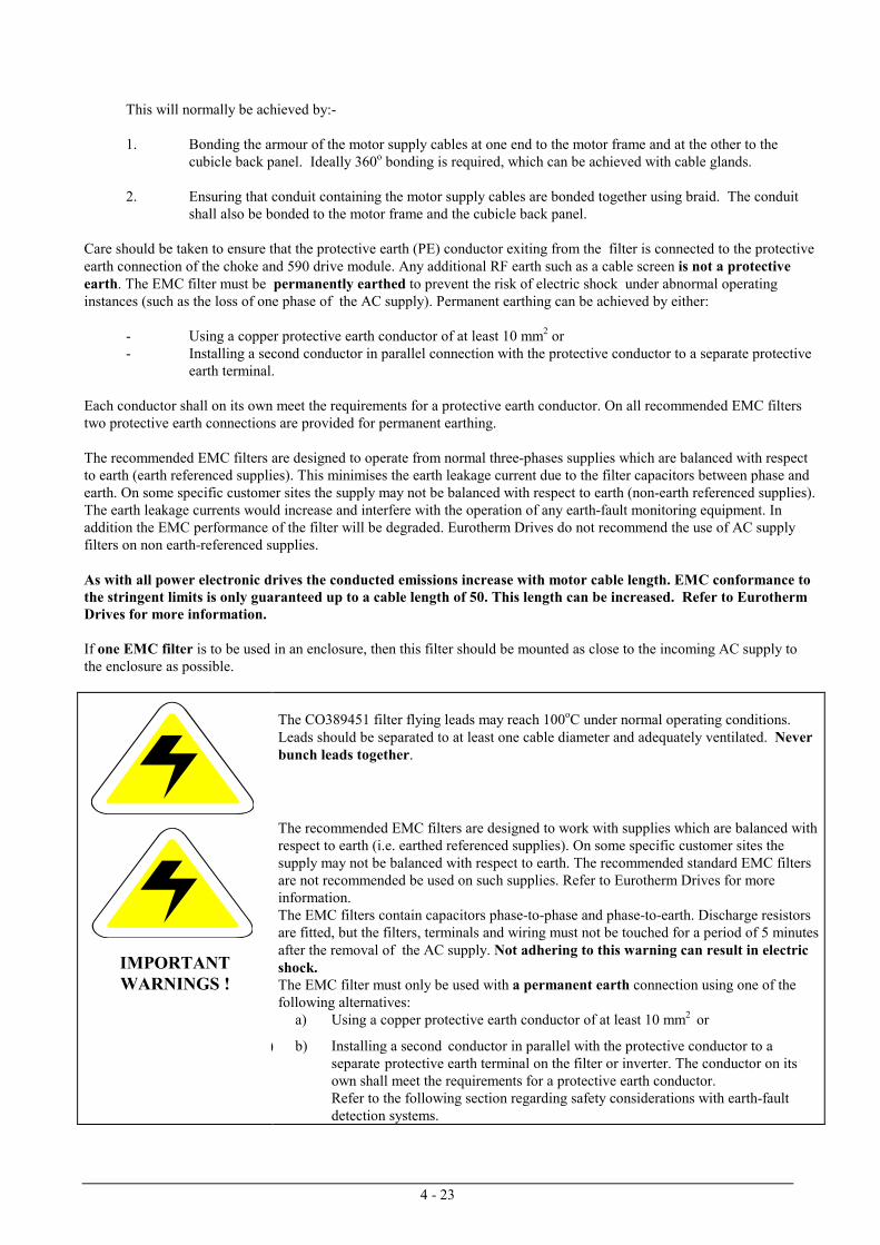
The CO389451 filter flying leads may reach 100oC under normal operating conditions.Leads should be separated to at least one cable diameter and adequately ventilated. Neverbunch leads together.
IMPORTANTWARNINGS !
The recommended EMC filters are designed to work with supplies which are balanced withrespect to earth (i.e. earthed referenced supplies). On some specific customer sites thesupply may not be balanced with respect to earth. The recommended standard EMC filtersare not recommended be used on such supplies. Refer to Eurotherm Drives for moreinformation.The EMC filters contain capacitors phase-to-phase and phase-to-earth. Discharge resistorsare fitted, but the filters, terminals and wiring must not be touched for a period of 5 minutesafter the removal of the AC supply. Not adhering to this warning can result in electricshock.The EMC filter must only be used with a permanent earth connection using one of thefollowing alternatives:
a) Using a copper protective earth conductor of at least 10 mm2 or
) b) Installing a second conductor in parallel with the protective conductor to a separate protective earth terminal on the filter or inverter. The conductor on its own shall meet the requirements for a protective earth conductor.Refer to the following section regarding safety considerations with earth-fault detection systems.

4 - 24
INTERACTION WITH EARTH-FAULT MONITORING SYSTEMS AND SAFETY CONSIDERATIONSDue to the EMC filter internal capacitors between phase and earth, on initial connection of the AC supply a pulse of currentwill flow in the earth. This has been minimised in the recommended EMC filters, but may still trip out any RCD (ResidentCurrent Detector) in the earth system. In addition high frequency and DC components of earth leakage currents will flowunder normal operating conditions. Under certain fault conditions, larger DC protective earth currents may flow. The pro-tective function of some RCDs cannot be guaranteed under such operating conditions. Eurotherm Drives do not recommendthe use of RCDs, but where their use is mandatory, they should be capable of correct operation with DC and AC protectiveearth currents (such as type B RCDs as in amendment 2 of IEC755) and have adjustable trip amplitude and timecharacteristics, to prevent nuisance tripping on initial power connection. RCDs used with 590 drive modules and othersimilar equipment are not suitable for personnel protection. Another means of providing personal safety must beprovided for, see EN50178/VDE0160.
MINIMISING RADIATED EMISSIONSAll 590 drive modules can be made to comply with the most stringent radiated emission limits of EN55011 (1991) Class Bby simply mounting inside an enclosure with 10 dB attenuation between 30 and 100 MHz (which would typically be theattenuation provided by a metal cabinet with no aperture greater than 0.15m) and screening any control and signal cablingoutside of the enclosure. The control and signal cables should be terminated at the entrance to the enclosure. Outside of theenclosure all cables must be screened. Inside the enclosure the radiated magnetic and electric fields will be high, due toproximity, and any components fitted inside the enclosure must be sufficiently immune. Remember that the EN55011radiated emission measurements are made between 30 MHz and 1 GHz in the far field, at a distance of between 10m and 30m. No limits are specified lower than 30 MHz, or in close proximity. Emissions from individual components tend to beadditive.
The cable between the enclosure and the motor must be screened or armoured (both field and armature) and should alsocontain the motor protective earth connection. The screen/armour must be earthed at both ends by connecting it to both themotor frame and the entrance to the cubicle, ideally in 360° termination's via cable glands (to meet the most stringentemission requirements). Screen to earth connections via 360° bonding is 75% more effective than earthing via pigtails(Note some motor gland boxes and conduit glands are made of plastic, if this is the case then braid must be connectedbetween the screen and the chassis, in addition at the motor end ensure that the screen is electrically connected to the motorframe since some terminal boxes are insulated from the frame by gasket/paint). Often the screens are terminated on a powerscreen rail at the entrance to the enclosure using ‘u’ clips to achieve a near 360o screen band. The integrity of the screenmust be maintained over the entire length of the cable between the enclosure and motor. If the cable is broken to insertterminals, contactors, chokes, fuses etc., then the screen must be connected over the shortest possible distance. Note somehazardous area installations may preclude direct earthing at both ends of the screen, in this case earth the other end via a 1µF, 50VAC capacitor. The motor protective earth should be connected to the drive module motor protective earthconnection.
If a shielded cable is not available, lay unshielded motor cables in a metal conduit which will act as a shield. The conduitmust be continuous with a direct electrical contact to the drive module and motor housing. If links are necessary, use braidwith a minimum cross sectional area of 10 mm2 .
Safety earthing always takes precedence over EMC earthing.
The use of screened cable without an EMC filter is not recommended, as line-conducted interference will increasesubstantially and the capacitive coupling of the output cable to earth will result in high earth-leakage currents.
To ensure the correct operation of the 590 drive module, some control and signal cables (encoder, all analogue inputs andcommunications) have to be screened back to the drive terminals inside the enclosure. The screen integrity must becontinuous right back to the drive if not connected to the cubicle. Always minimise the length of screen stripped back tomake this connection. The screen should only be connected at the drive end. If high frequency noise is still a problem, earthat the non drive end via a 0.1 µF capacitor.
SCREENING AND EARTHING WHEN MOUNTED IN AN ENCLOSUREMake sure the requirements of EN60204 are adhered to with electrical equipment for machines. Satisfactory EMCperformance is only achievable when the 590 drive module, filter, choke and associated equipment is mounted on aconducting metal mounting panel. Beware of constructions using insulating mounting panels or undefined mountingstructures A single point earthing strategy should be followed as closely as possible for a single drive module mounted inan enclosure as shown in figure 4-6. The protective earth connection (PE) to the motor must run inside the screened cablebetween the motor and 590 drive module, where it is to be connected near to the motor protective earth terminal on thedrive module as shown in figure 4-6. (Note in accordance with EN60204 only one protective earth conductor is permitted ateach earth terminal contacting point). Local wiring regulations may require the protective-earth connection of the motor tobe connected locally but this will not cause shielding problems due to the relatively high RF impedance of the local earthconnection.

4 - 25
AC Supply Filter + Choke Motor Cable Screen Motor
SafetyEarth
PE
PE
PE
DC
PE
As shortas possible In close proximity
to drive
Fig. 4-6: Screening and earthing of a single 590 drive module.When more than one piece of electrical equipment is fitted inside an enclosure, care must be taken to ensure that noiseflowing in the earth connection does not couple into other equipment. A star-point earthing policy separating noisy fromquiet earths is strongly recommended. Five separate earths branches should be provided for:
♦ Clean earth busbar The Clean earth busbar is used as a reference point for all signal and control cabling. This may thefurther subdivided into an analogue and a digital reference busbar, each separately connected tothe star earthing point. The digital reference is also used for any 24V control.
♦ Dirty earth busbar The dirty earth busbar is used for all power earths (i.e. protective earth connections)
♦ Enclosure metalworkbusbar
The enclosure metalwork busbar is used for all parts of the cubicle including panels, doors andback plate. It is also used as a reference for any 110 or 220V control used and for the controltransformer screen.
♦ Power screen busbar The power screen busbar is only for power screened cables which do not have to go directly to the590 drive module (such as motor cables, braking choppers and their resistors) or to other drivemodules (refer to appropriate Product Manual to identify these). Noise coupled onto the incomingscreens must flow to earth directly so as not to contaminate the rest of the cubicle. Hence thepower screen busbar should be placed as close to the point of cable entry as possible.
♦ Signal/control screenbusbar
The signal/control screen busbar is to be used for signal/control screened cables which do nothave to go directly to the 590 drive module. This busbar should also be placed as close as to thepoint of cable entry as possible.
For optimum EMC performance, copper rails with a substantial cross-section should be used for the busbar. Screenedcables are best ‘u’ clamped to the busbars to ensure an optimum HF connection.
The five separate earth busbars should be insulated from the mounting panel and connected to a single earth point (starpoint) near the PE or PEN terminal of the main supply. Flexible large cross-section cable to ensure a low HF impedanceshould be used. The arrangement of the busbars should be such that the connection to the single earth point are as short aspossible. Fig. 4-7 shows an implementation of a star-point earthing policy.

4 - 26
Analogue Clean Earth
Dirty Earth
Digital Clean Earth
Metal Work Earth
AC/DC AC/DC AC/DCPLC
PE PE
PE
0D 0D 0D
0D
0A 0A 0A
DoorsBackplate
Metal Work
110VControl
24VControl
UnscreenedSignals
UnscreenedSignals
STAR POINTIncoming Safety Earth
To Motor To Motor To Motor
Screened ScreenedPE = protective earthOA = analogue 0voltsOD = digital 0volts
PE
Sig/cntrl Screen
Power Screen Earth
Fig. 4-7: Implementation of star-point earthing policy for multi-drive installation
OTHER LAYOUT CONSIDERATIONSThe proximity between the source and victim circuit has a large effect on radiated coupling. The electromagnetic fieldsproduced by drive modules falls off rapidly with distance from the cabling/enclosure. It should be remembered that theradiated fields from EMC compliant drive systems are measured at least 10m from the equipment over the frequency band30 to 1000 MHz (as required by EN55011, referenced by the generics and the drive product specific standard). Anyequipment placed closer to the drive system than this will see larger magnitude fields, particularly very close to the drive.No magnetic/electric field sensitive equipment should be placed within 0.25m of the following parts of a drive system:
- 590 Drive module
- EMC output filters
- Input or output chokes/transformers
- Cable between 590 Frequency Inverter and Motor (even when screened/armoured)
- Connections to external braking chopper and resistor (even when screened/armoured)
- AC/DC brushed motors (due to commutation)
- DC link connections (even when screened/armoured)
- Relays and contactors (even if they are suppressed)

4 - 27
Often the coupling between electrically 'noisy' and 'sensitive' cables is a problem. This can be minimised by separatingparallel runs by at least 0.25m, and minimising the length of parallel runs. For long parallel runs (>10 m) the separationshould be increased proportionally. For example if the parallel runs were 50 m then the separation would be (50/10) × 0.25m = 1.25 m.
In addition the coupling between two cables which must cross is minimised if they cross over at 90°. Hence sensitive cablesshould cross the cables to the motor, DC link and braking chopper circuit at 90°, and should never be run close to them orin parallel for any great length.
Never run supply, DC link or motor cables in the same bundle as the signal/control and feedback cables, even if they arescreened.
From experience the following equipment is defined as particularly sensitive and care must be taken in the installation:
- Any transducers which produce low level analogue outputs (<1 volt) e.g. load cells, strain gauges,thermocouples, piezoelectric transducers, anometers, LVDT's
- A.M. radios (long and medium wave only)- Video cameras and closed circuit TV- Office personal computers- Capacitive devices such as proximity sensors and level transducers- Mains borne communication systems- Equipment not suitable for operation in the intended EMC environment i.e. with insufficient immunity to new
EMC standards

5 - 1
5. TERMINAL DESCRIPTIONS
5.1 CONTROL BOARD TERMINAL DESCRIPTIONS
* These Terminals should be left open-circuit if not used.
1. AC TACH INPUT2. AC TACH INPUT
These terminals provide input for AC tach speed measurement, rectification and filtering are provided.Selection of AC tach feedback is made via switch 1 selection. The maximum value of AC tach voltage at fullspeed must not exceed 200V peak.Refer to calibration section - for maximum speed adjustment.
3. DC TACH INPUT (Alternative input on terminal 17)These terminals provide input for DC tach speed measurement.
Selection of DC tach feedback is made via switch 1 selection.For forward motor rotation corresponding to a positive Total Setpoint signal , the Tach feedback voltage atterminal 3 (or 17) must be positive with respect to 0V. Tach feedback voltages up to 200V should be applieddirect to terminal 3 (or 17) If the full speed Tach feedback exceeds 200V, an additional calibration resistor mustbe added, external to the controller.Refer to calibration section - for maximum speed adjustment.
4. OVZero Volt reference.
5. ARMATURE CURRENT COMPENSATION OUTPUTThis output is a Buffered Bipolar Armature Current Feedback Signal of +/-1.11V = +/-100% Full Load
Current.In Armature Voltage Feedback applications, up to 11% IaRa Compensation can be derived from this Output,adjustable by an external control potentiometer. The control should be a 10K Ohm potentiometer, connectedbetween Terminals 5 and, 4 with its wiper connected to Terminal 9 or 10.
6. SETPOINT RAMP RESET*Connect to 0V to reset the Setpoint Ramp Output to zero volts, otherwise leave open circuit. The reset
is instantaneous and independent of the setting of preset potentiometers P1 and P2.
Note: Option switch, S8/6 allows the setpoint ramp generator reset to be disconnected from the driveinternal reset.
7. SETPOINT RAMP INPUT*Speed reference input to the Setpoint Ramp circuit. Maximum input = +/-10V with respect to 0V, input
impedance = 200K Ohms. See also Inverted Subtotal, terminal 11 and Total setpoint terminal 13.
8. SETPOINT RAMP OUTPUTUnder steady-state conditions this output voltage will equal the input voltage on Terminal 7 However,
when the input voltage is changed, the output will follow at a constant rate dependant upon the settings of presetsP1 and P2. These are the Positive Rate and Negative Rate potentiometers, sometimes referred to as Up Rate andDown Rate respectively. They are adjustable over the range 0.25 to 7.5 seconds when Option Switch S8/4 is ONand 5 to 75 seconds when S8/4 is OFF. Note that "Positive" and "Negative" do not refer to the actual polarity ofthe Setpoint Ramp Output but to the direction in which it is changing. For example if the Setpoint Ramp Input ismore positive that it's Output then the rate of change will depend on the setting of the Positive Rate Control.Conversely, if the Input is more negative than the Output, the rate will depend on the setting of the Negative Ratecontrol.
When Option Switch S8/3 is ON the Setpoint Ramp Output is summed internally with any inputsappearing at Terminals 9,10 and 12. When S8/3 is OFF the Output is internally isolated from the other inputs butmay be connected externally to 9,10 or 12 if required.
The Ramp Output is reset to zero if Terminal 6 is connected to 0V or if the Run/Inhibit signal is in theInhibit state (LED 5 not lit). See also Inverted Subtotal, terminal 11 and terminal 13 Total Setpoint.

5 - 2
9. INPUT NO. 1*Speed Reference input. Maximum input = +/-10V with respect to 0V, input impedance = 20K Ohms.
See also Inverted Subtotal, terminal 11 and Total Setpoint terminal 13
10. INPUT NO. 2*Speed Reference input. Maximum input = +/-10V with respect to 0V, input impedance = 20K Ohms.
See also Inverted Subtotal, terminal 11, and Total Setpoint, terminal 13.
11. INVERTED SUBTOTAL OUTPUTEqual to the inverted Algebraic sum of Input No. 1, Input No. 2 and the Setpoint Ramp Output
provided that Option Switch S8/3 is ON, otherwise equal only to the inverted algebraic sum of Inputs No. 1 andInput No. 2. See also Total Setpoint, terminal 13 .
12. INPUT NO. 3*Inverted Speed reference input. Maximum input = +/-10V, input impedance = 20K Ohms. This input
is of the opposite sense to Inputs No. 1, No. 2 and the Setpoint Ramp Input i.e. if maximum forward speed isrequired, it can be achieved by applying +10V, to Input No. 1 (or Input No. 2 or the Setpoint Ramp Input) or byapplying -10V to Input No. 3. See also Total Setpoint, terminal 13.
13. TOTAL SETPOINT OUTPUTThis buffered output is the inverted sum of the Inverted Subtotal Output and Input No. 3. Thus it is
equal to Input No. 1, plus Input No. 2, plus the Setpoint Ramp Input (if applicable - see 6 and 8), minus inputNo. 3. The maximum output is limited to approximately +/-11V. In 591A and 599A controllers a Total Setpointsignal of +10V represents a demand for full speed. In the 590A and 598A regenerative controllers +10Vdemands full forward speed and -10V demands full reverse speed.
14. +10V PRECISION REFERENCESetpoint reference supply. This supply is short-circuit proof, but for normal operation the load on
Terminal 14 plus Terminal 24 should not exceed a total of 5mA.
15. -10V PRECISION REFERENCESetpoint reference supply. This supply is short-circuit proof, but for normal operation the load current
should not exceed 5mA. This supply is not normally used in the case of non-regenerative controllers (types591A and 5994).
16. 0V Zero voltage reference.
17. TACH INPUT - Refer to Terminal 3
18. CURRENT DEMAND ISOLATE*Connect terminal 18 to 0V to cause disconnection of the current demand signal from the input of the
current loop. This facility may be required in some Torque Control or special applications where the CurrentDemand signal is input to the Current Loop via Terminal 20 (See 20 and 21). For Speed Control applicationsthis Terminal is normally left open circuit.
19. CURRENT DEMAND OUTPUT*This Current Demand signal is the output from the speed loop integrator It is connected directly to the
input of the Current Loop except when Current Demand Isolate is at 0V (See Terminal 18 description).In Speed Control applications the voltage at terminal 19 depends upon the motor speed and load
conditions. Zero volts represents a demand for zero Armature current while +10V and -10V represent a demandfor +200% and -200% of Full Load Current respectively.
In the case of 591A and 599A Controllers the Current Demand signal must be positive for Armaturecurrent to flow. The maximum level of this signal is later modified by the Current Limit circuit (according to theinput voltages of terminals 22,23 and 25) before comparison with the Current Feedback signal.
20. AUXILIARY CURRENT INPUT*This Terminal allows direct access to the input of the Current Loop and is used for some Torque
Control and special applications. An input at this Terminal will be connected to the input of the Current Loop ifTerminal 21 is connected to 0V. Connect Terminal 18 to 0V to prevent addition of the current Demand signal tothe Auxiliary Current Input Signal. An Auxiliary Current Input of 0V represents a demand for zero Armaturecurrent while +10V and -10V represent a demand for (+200%) and -200% of full Load Current respectively. Inthe case of 591A and 599A controllers the Auxiliary Current Input signal must be positive for Armature current

5 - 3
to flow. The maximum level of this signal is later modified by the Current Limit circuit (according to the inputvoltages at terminals 22,23 and 25) before comparison with the Current Feedback signal
21. SELECT AUXILIARY CURRENT INPUT*If this Terminal is connected to 0V any input at terminal 20 will be connected through to the input of
the Current loop and will be added to the Current Demand Signal (see also Current Demand Isolate, Terminal18). In Speed Control applications Terminal 21 is normally left open circuit.
22. AUXILIARY CURRENT LIMIT (+) POSITIVE *This input provides independent control of the positive Armature current limit, from zero up to the
maximum allowed by the Main Current Limit setting (see terminal 23 description). If this facility is not requiredTerminal 22 should be left open circuit, in which case Auxiliary Current Limit (+) is disabled by an internal pull-up resistor and control reverts to the Main Current Limit.
The control voltage range at Terminal 22 is 0 to +10V = 0 to +200% Full Load Current. The inputimpedance is approximately 25K Ohms. Because of the internal pull-up resistor adjustment of the terminalvoltage can be made by an external resistor connected between 22 and 0V. Alternative methods of control are apotentiometer (ends connected to 24 and 0V, wiper to 22) or an analog voltage in the range 0 to +10V. Negativevoltage MUST NOT normally be applied to this input.
23. MAIN CURRENT LIMITThe Main Current Limit provides symmetrical control of both positive and negative Armature current
limits. If different positive and negative current limits are required see 22 and 25 when external control of theMain Current Limit is not required 23 should be connected to +10V (Terminal 24). The input voltage atTerminal 23 supplies the Main Current Limit preset potentiometer P7, thus the actual current limit valuedepends upon the voltage at 23 and the setting of P7. Assuming that P7 is set fully clockwise, the controlvoltage range at Terminal 23 is 0 to +10V = 0 to +/-200% Full Load Current (0 to +200% Full Load Current inthe case of 591A and 599A controllers). A negative input voltage MUST NEVER be applied to this Terminal.
24. +10V PRECISION REFERENCESetpoint reference supply. This supply is short-circuit proof but for normal operation the load on
Terminal 14 plus Terminal 24 should not exceed a total of 5mA.
25. AUXILIARY CURRENT LIMIT (-) NEGATIVE *This input provides independent control of the negative Armature current limit, from zero up to the
maximum allowed by the Main Current Limit setting (see terminal 23 description). If this facility is not required(and in all 591A and 599A applications) Terminal 25 should be left open circuit, in which case the AuxiliaryCurrent Limit (-) is disabled by an internal pull-up resistor and control reverts to the Main Current Limit.
The control voltage range at Terminal 25 is 0 to -10V = 0 to -200% Full Load Current. The inputimpedance is approximately 25K Ohms. Because of the internal pull-up resistor adjustment of the Terminalvoltage can be made by an external resistor connected between terminal 25 and 0v. Alternative methods ofcontrol are a potentiometer (ends connected to 15 and 0V, wiper to 25) or an analog voltage in the range 0 to -10V. Positive voltages MUST NOT normally be applied to this input.
26. BUFFERED TACH OUTPUTThis output has the same polarity as the Tach input voltage on Terminal ( 1&2 for AC Tachs, or 3, or
17, for DC Tachs) but is attenuated so that 0 to +/-100% Full Speed is represented by an output of 0 to +/-10V.The output is short-circuit proof and may be used to supply speed indicator or speed sensing circuits up to amaximum load current of 5mA.
27. BUFFERED CURRENT OUTPUTThis output is short-circuit proof and may be used to supply Armature current Indicators or sensing
circuits up to a maximum load current of 5mA. Modulus or Bipolar outputs are available depending upon thesetting of Option Switch S8/1. For centre-zero indicators S8/1 should be ON (UP) so that the output is Bipolari.e. positive and negative Armature currents are represented by positive and negative outputs at Terminal 27.
For end-zero indicators S8/1 should be OFF (DOWN) so that the output represents the Modulus of theArmature current i.e. both positive and negative Armature currents are represented by a positive output atterminal 27. In either case an output of 10V represents an Armature current of 200% Full Load, 5V represents100% Full Load Current etc. In 591A and 599A applications the setting of S8/1 is immaterial since these unitsonly produce positive Armature current.

5 - 4
28. OVZero Volt reference
29. THERMISTOR/MICROTHERMMotor overtemperature sensors should be connected between Terminals 28 and 29. The drive will be
disabled if the external resistance between 28 and 29 exceeds 1.8K Ohms +/-200 Ohms (see 35 and 37 Terminaldescriptions). THE DRIVE MAY RESTART AUTOMATICALLY WHEN THE RESISTANCE (I.E.MOTOR TEMPERATURE) FALLS - see Terminal 30 description. Suitable temperature sensors arethermostatic switches (e.g. microtherms) or a pair of series connected P.T.C. thermistors. If over temperaturesensors are not used Terminals 28 and 29 must be linked.
30. AUXILIARY ENABLEThis input is normally connected to Terminal 31. If required, external normally-closed interlock
contacts may be inserted between Terminals 30 and 31.The drive will be disabled when the input to 30 is open circuit or if the input voltage is less than
approximately +10V (see 35 and 37 Terminal descriptions) and enabled at +24V.NOTE:The Thermistor/microtherm and Field failure alarms normally disable the drive only while a fault exist;
if the fault clears, because the motor cools down for example, the motor will restart automatically. However,these alarms can be made to latch the drive in the disabled state indefinitely by connecting 30 to 37 (anyexternal interlock contacts connected in the 30 to 31 link will also be latched in this manner). In this mode aThermistor/microtherm, Field failure or external interlock alarm condition can only be cleared, and the motorrestarted, by operating the start/stop controls. Also see option switch S8/5
31. START SUPPLYThis terminal is normally connected to Terminals 30 and 32 and to the Start/Stop control circuit.In systems employing separate momentary contact Start and Stop switches, 31 should be connected to
the normally closed Stop contact. If a single maintained contact Start/Stop switch is used it should be connectedbetween Terminals 31 and 34. The Start supply is present whenever the Auxiliary Supply is on (see D7 and D8terminal descriptions).
32. ENABLENormally connected to Terminal 31, the drive will be disabled when this input is open circuit or when
the input voltage is less than approximately +10V, and enabled at +24V.
33. STOPIn systems employing separate Start and Stop controls this Terminal is wired to the common
interconnection point of the two switches. If a single maintained contact switch is used for Start/Stop controlthen no connections should be made to this Terminal. (See also 31 and 34 Terminal description).
34. STARTWhen the Start Supply from Terminal 31 is applied to this Terminal via the Start control, the internal
contactor control relay will be energised. This in turn will energise the (external) three phase supply contactor.If separate Start and Stop controls are used 34 should be connected to the normally open, momentary contact ofthe Start switch. When Stop/Start control is by a single maintained contact it should be connected betweenTerminals 31 and 34. See also Terminal 31 description.
35. READY OUTPUTThis is the output of a fault detector circuit which monitors 8 internal Alarm signals. Its output is
approximately +24V volts at 50mA maximum and may be used to supply an external indicator or relayconnected between Terminals 35 and 0V. The drive will run when this output is high (+24V) and the Enableinput Terminal 32 is high (+24V).
The Ready Output will be high when all of the following condition are met:-1) Single phase Auxiliary Supply present, fuse FS1 good and the Preset board
correctly inserted.2) Drive synchronised to supply frequency in the range 45 to 65 Hz.3) Three phase supply present, fuses all good ( FS2, FS3 and FS4)4) Field current present (or Field Failure override selected) and Stack Thermal Trip
not open (force ventilated units only).5) Start instruction issued, contactor control relay latched, three phase contactor closed.6) Resistance between Terminals 0V and 29 (Thermistor/microtherm) less than
approximately 1.8K Ohms +/-200 Ohms.

5 - 5
7) Auxiliary Enable input voltage (Terminal 30) +24V.8) Armature current waveform normal.
36. ZERO SPEED RELAY DRIVEThis output is intended to supply a +24 volt (D.C.) relay at an output current not exceeding 50mA. The
relay should be connected between Terminals 36 and 0V; it will be energised when the Speed Feedback signal islower than the Standstill Threshold set by preset potentiometer P4 (P4 has a range of +/-0.5 to +/-4% of FullSpeed).
37. HEALTH RELAY DRIVEThis output is intended to drive a 24 volt (D.C.) relay at an output current not exceeding 50mA. The
relay should be connected between Terminals 37 and 0V; it will be energised when terminal 37 is high (+24Vnominal) and de-energised when 37 is low (0V).
When the Auxiliary Supply is connected to the drive the relay will energise and will only be de-energised if the Ready Output (Terminal 35) is disabled while the Start Supply is present at Terminal 34.
This output can also be used to latch the Thermistor/microtherm, Field failure and external interlockalarms -( see Terminal 30 description.) by linking 30 to 37.
The Health output at terminal 37 depends upon the Stop/Start condition of the drive, as follows:i) When the drive is in the Start condition (Start Supply present at Terminal 34), the output
at 37 depends upon the Ready Output at 35,i.e. 37 will be high if 35 is high, 37 will be low if 35 is low.
ii) When the drive is in the Stop condition the output at Terminal 37 will always be high,even though the Ready Output is low.
38. +24V (NOMINAL)This is a +24V unregulated D.C. supply which may be used to supply the Enable and Fault Reset
(External) inputs (maximum output 6W or 250mA).
39. FAULT RESET (EXTERNAL)If external Fault Reset control is required connect this Terminal to +24V (38) via a normally open
momentary contact.
5.2 POWER BOARD TERMINAL DESCRIPTIONS
NOTE: Power board terminals are located on the power board behind the control board and are given the prefix 'D', so as to avoid confusion with control terminals.
D1 } EXTERNAL AC SUPPLY TO FIELD BRIDGED2 }
NOTE: The actual magnitude required will depend upon the motor field rating and the setting of the field optionswitches S9/1 - S9/4 and P11.
1. When using an external AC input, it is important to have the correct phase relationship onthe terminals The supply must be delivered from L1 (red) and L2 (yellow) phased directly or indirectly through atransformer:
L1 MUST BE CONNECTED TO D1L2 MUST BE CONNECTED TO D2
2. The voltage applied to the external AC terminals must not exceed 500V.D3 FIELD OUTPUT NEGATIVED4 FIELD OUTPUT POSITIVE
The DC output voltage at these terminals will depend upon the AC supply voltage and the field bridge regulatoroption switches S9/1 - S9/4 and P11.
D5 MAIN CONTACTOR COIL LThis terminal is the switched output from the contactor control relay and is derived from the auxiliary supply atterminal D8. The output is internally fused at 3A, hence contactor coils having a high pick-up current must beoperated via a slave relay.

5 - 6
NOTE:- The contacts of the Contactor Control Relay are suppressed by a series connected resistor (680 ohms)and capacitor (22nF) to protect the relay contacts. Users should be aware that when the contactor Control relayis “De-energised”, a leakage current of approximately 2mA can be expected and this should be considered wheninterfacing to these terminals. Typically, there could be the energisation of very sensitive relays.
D6 MAIN CONTACTOR COIL NThis terminal is internally connected to the auxiliary supply neutral and provides a convenient connection pointfor the contactor coil neutral connection.
D7 AUXILIARY SUPPLY (NEUTRAL)D8 AUXILIARY SUPPLY (LIVE)These terminals are the auxiliary connections for the control power switch mode supply, contactor control relaysupply and cooling fan supply (when force cooled). The voltage applied to these terminals is product codedependent (only for fan supply). The switch mode power supply is auto ranging from 110 - 240, 50/60 Hz.
Additions to Technical ManualSubject-External Supply Terminals D1 & D2These terminals are used for the External AC Supply connection (for the Motor Field Supply) when the InternalAC Supply is unused. The following actions must be taken:1) These terminals are now energised when “Internal Field Supply” option is used, and the 3 phase supply(L1/2/3) is energised. Protection is available via the on-board Field supply fuses FS2, FS3.2) When utilising the “External AC Supply” connection, internal wiring links must be removed and connected tostaging posts provided.The internal wiring links (Red and Yellow) are identified by the following procedure (refer to sheet 2)a) Isolate the Driveb) Loosen control board fixing screws (2 off) and orientate control board to allow access to power board.c) Identify internal field supply link (colour-Red) where it is connected by “Faston” at the left hand side ofTerminal D1. Remove this link from the faston connection and place on staging post “F8” located to the left. (Toenable positive identification of the correct link, Faston F8 should now be connected to FS2, and L1. Verify bycontinuity test)d) Identify internal field supply link (colour-Yellow) where it is connected by “Faston” at the mid-point belowterminals D1 & D2. Remove this link from the faston connection and place on staging post “F16” located to theleft. (To enable positive identification of the correct link, Faston F16 should now be connected to FS3, and L2.Verify by continuity test)e) The External Field Supply can now be connected via externally mounted fast acting 20 Amp fuses. (Note thatthe phase of D1 must be derived from L1, and the phase of D2 must be derived from L2).
POWER BOARD AH385621
D1 D2 D3 D4
Red
F8
F16
Yellow

6 - 1
6. BLOCK DIAGRAM DESCRIPTION
6.1. POWER CONFIGURATION
Three phase power is supplied to the AC input terminals (L1, L2 and L3) of the drive via an external isolatingcontactor. The phase rotation (phasing) of the supply is unimportant. Three auxiliary fuses (FS2, FS3 and FS4 )protect the internal power wiring and suppression networks.The thyristor stack is fully suppressed to prevent damage caused by over voltage or supply borne transients.
FIELD SUPPLYThe DC supply for field excitation is available from terminals D3 (positive) and D4 (negative), and is adjustableto suit the application by using S9/4 and P11.The field current is measured using a small AC current transformer to provide an isolated logic signal which fallsto zero and inhibits the drive in the event of "field failure" (Diagnostic 7). The field failure condition can beoverridden when required by the selection of option switch S9/5 .
AUXILIARY SUPPLYThe auxiliary single phase AC supply which power the drive electronics is connected to terminals D8 (line) andD7(neutral). The line supply is fused via a 3Amp control fuse (FS1), to the switch mode power supply (110V -240V) and the contactor control relay within the drive, it also provides the fan supply in force ventilated units.
CONTACTOR CONTROLThe contactor control relay is operated from the isolated low voltage drive at terminal 31 via external Stop/Runpushbuttons., or maintained run contact. Its suppressed power contacts provides a switched version of theauxiliary line voltage on terminal D5 (line) and D6 (neutral) to energise the isolating contactor. The contactorcontrol relay may be de-energised in the event of detecting abnormally high armature current in the motor andwill hence remove the 3-phase supply from the drive. Drive Condition Indicator LED 4 will be extinguished anduntil the Fault Reset push button is operated (or the external reset from terminal 39) the isolating contactorcannot be re-energised. The switching capability of the internal relay is 3 Amps inductive up to 240V AC max.For contactors with higher voltage or current ratings, an external slave relay should be interposed between theinternal relay and the three phase isolating contactor.
SYNCHRONISATIONIsolated synchronising signals to ensure the correct firing sequence of the six or twelve bridge thyristors arederived from the fused 3-phase supply lines via two high impedance differential amplifiers and an opticallycoupled isolator. The synchronising circuits are insensitive to variation of the following supply parameters.
i) Phase Rotationii) Supply voltage (over the range 220-500V +/-10%)iii) Supply frequency (over the range 50-60Hz +/-5%)This caters for all world wide supply conditions.If one or more of the supply lines is lost or if a fuse (FS2-FS4) ruptures the drive is held in inhibit,
Indicator 3 will extinguish and no power will be delivered to the load.
6.2. THE CONTROL OPERATION
ISOLATIONThe drive control circuits are fully isolated from the Auxiliary and 3-Phase Mains Supplies and this is indicatedon the block diagram by the dotted isolation boundary on the right;
i.e. 1. Armature current is sensed by the 2 line AC current transformers to provide an isolated and normalisedsignal of 1.1V = 100% Full Load.
2. Synchronising signals are provided by two high impedance differential amplifiers and an opto-isolator. 3.Thyristor gate pulses are independently isolated by 6 or 12 pulse transformers on the trigger board. 4. Field current is sensed via an AC current transformer to provide an isolated field failure alarm signal.

6 - 2
5. An isolated speed feedback signal is provided by a tach or from the armature voltage using a 5590Armature voltage isolation amplifier. It is then normalised to 10V = 100% Full Speed.
6. Isolated control power supplies are generated from the Auxiliary Supply by the switch mode supplytransformer. 7. Control of the 3-phase contactor coil is isolated by allowing Start and Stop buttons to operate an internalslave relay driven from a low voltage (24 Volts nominal control signal).
POWER SUPPLIESStabilised internal supplies of +/-15 volts DC (Diagnostics 1 and 4 respectively) and +/-10 volts DC (referencequality) are generated from the single phase Auxiliary Supply via the switch mode transformer. The external +/-10V DC supplies (Diagnostics 2 and 3 respectively) are buffered within the drive. A smoothed unstabilised railof 24 Volts Dc nominal, is available at terminal 38 for higher current requirements. These rails are protectedagainst accidental short term overloads and fuse, FS1 (3A) on the Power Supply P.C.B. protects the wiring.
SPEED REFERENCE4 Quadrant Operation: The speed signal is ten volts positive, to ten volts negative, corresponding to
full speed forward and full speed reverse and is fed into terminal 7, Setpoint Ramp Input (Diagnostic 11). It canbe generated by connecting a potentiometer (typical value 10K Ohms) from +10V (terminal 14) and -10V(terminal 15), or by feeding in +/-10 volts from an external source. Zero volts corresponds to zero speed.
2 Quadrant Operation: The speed signal is ten volts positive, to zero volts, corresponding to full speedforward and zero speed, and is fed into terminal 7 , Setpoint Ramp Input (Diagnostic 11). It can be generated byconnecting a potentiometer (typical value 10K Ohms) from a +10V (Terminal 14) and 0V (Terminal 4), or befeeding in +10 to 0 volts from an external source.
The setpoint is rate limited by a linear ramp generator which has independent adjustable Up (P1) andDown (P2) rates. The span on these rates is also adjustable using switch S8/4. The Setpoint Ramp Output isbrought out to terminal 8 so that other drives may share it as a common setpoint. The Ramp Output is reset tozero when the drive is in an inhibit condition, it may also be reset externally by applying 0V to terminal 6, (whenthis function is not required terminal 6 is left open circuit).
Three alternative input channels are available which by-pass the ramp unit, these are labelled SetpointNo. 1, (terminal 9, Diagnostic 12), Setpoint No.2, (terminal 10, Diagnostic 13), and Setpoint No.3, (terminal 12,Diagnostic 14), they each have the same sensitivity as the main input channel.
The total sum of the input is available as Total Setpoint on a buffered output terminal 13(diagnostic15).
The algebraic summation of all these input channels is: Ramp input (7) + SP.No.1(9) + SP. No.2(10) -SP.No.3(12) = Total SP.(13) An Inverted Subtotal is also available on terminal 11, which is the summation of two inputs: SP.No.1(9) + SP.No.2(10) = Inverted Subtotal(11)
NOTE:The Setpoint Ramp Output is only available internally if option switch S8/3 is closed, otherwise it is completelyisolated from the rest of the drive.
It is recommended that all setpoint connections are made using screened leads. Unused inputs can be left opencircuit.
SPEED FEEDBACKSpeed feedback can be provided by either an AC or DC tach, via the selection switch S1 and the appropriateterminals i.e.
AC Tach - Terminals 1 & 2DC Tach - Terminal 3 (Positive)
Terminal 4 (Negative) 0V
Note: Terminal 17 is an alternative connection to Terminal 3.
When using an AC tach, internal rectification and filtering is provided. Additional filtering, if required is alsoprovided by S8/8 (time constant 10ms).

6 - 3
The speed feedback is scaled within the drive using the calibration switches for coarse adjustment:
S2 - 0/100 VoltsS3 - 0/ 90 VoltsS4 - 0/ 9 Volts
This allows an adjustment calibration factor for full speed up to 199 Volts. P10 on the preset board will allowfine adjustment of the top speed.
If tach voltages exceed 200V then external resistors should be added.
The drive also contains protective circuitry such that in the event of loss of speed feedback (i.e. tach failure) themotor speed will not rise excessively. This action occurs when the speed feedback term is less than 0.5% to 4%,(adjustable using trimpot. P4 on the Preset Board) and limits the maximum output voltage of the drive. Thiscondition still allows rated armature current to be produced at low speed and when the speed feedback termexceeds this level, (confirming tach operation) the limit is removed and normal control action is resumed.
Armature voltage feedback is available by using the armature voltage isolation unit 5590
ZERO SPEED SENSINGWhen the speed feedback signal is less than 0.5% to 4% (as set by P4) the Zero Speed Relay Driver is energisedsuch that external terminal 36 sources +24V to drive an external relay.
SPEED ERRORThe combined setpoints are compared with the tach feedback signal on an error amplifier (Diagnostic 17) suchthat the Speed Signal is always made equal to the Total Setpoint. An offset trimpot P3 is available on the PresetBoard to allow the offsets to be reduced to zero. It is not possible to achieve zero speed on demand of a zerospeed setpoint without the motor shaft creeping round at a very low speed however accurately the offset istrimmed. However, if absolute zero speed is required, then operating Option Switch S8/2 will enable theStandstill Logic. This will operate when the Total Setpoint is below 0.5% and the motor speed is below 4% -0.5% as set by trimpot P4. In this condition a quench action is employed and no firing pulses are applied to thethyristor bridge. If however the Total Setpoint or the speed feedback exceed the thresholds the Standstill Logicwill be disabled, the quench action removed and firing pulses are again applied to the thyristor bridge, thusallowing armature current to flow.
The gain of the Error Amplifier is adjustable (by P5 on the Preset Board) over a 10 to 1 range to provide controlof the stability and dynamic performance of the drive. This adjustment does no affect the steady state speedholding accuracy of the drive.
CURRENT DEMANDThe error signal is passed through a 2-Term (Proportional plus Integral) amplifier (Diagnostic 18) which ensuresvery high DC loop gain, thus achieving accurate steady state speed control and good dynamic performance bycorrectly optimising the low and high frequency gain of the system for small and large signals. The Integral timeconstant is adjustable over a 10 to 1 range using trimpot P6 on the Preset Board. The output of this 2-Termamplifier becomes the armature Current Demand signal under normal condition and is also available on externalterminal 19. However it may be isolated from the following stages by a solid state switch when terminal 18(Diagnostic 19) is connected to 0V, (otherwise this terminal is left open circuit). The auxiliary current input(terminal 20), diagnostic 20 can also provide the Current Demand signal or be algebraically added to the 2 Termoutput. via a solid state switch. If this facility is required terminal 21 (Diagnostic 21) must be connected to 0V,otherwise this terminal is left open circuit.
MAIN CURRENT LIMITThe Armature Current Demand signal then controls the magnitude of armature current and hence clamping themaximum excursion of this signal limits the maximum armature current that can flow. The reference for theclamp is taken from trimpot P7 on the Preset Board. The top of this potentiometer is available externally atterminal 23 and is normally connected to terminal 24 (+10V), thus +10V as measured on the wiper of P7(Diagnostic 24) corresponds to 200% armature current can be programmed according to some other controlstrategy.

6 - 4
For any current setting between 110% and 200% of full load, the actual current level is monitored by anoverload integrating circuit. The output of this circuit pulls down the current limit setting progressively to110% at a rate which is proportional to the overload magnitude,
i.e., An inverse time characteristic which typically allows 200% current for ten seconds after which the level isautomatically reduced to 110% , on a time curve which would allow 150% for about 30 seconds, and so on.
Reduction of the overload produces resetting of the overload capability in the same way. i.e. The lower the current level is taken below 100%, and the longer it spends below 100%, then the faster thereset for 200% capability.
AUXILIARY CURRENT LIMITSTwo auxiliary current limit clamps are also provided, one acting on the demand for positive current, the otheracting on the demand for negative current (in 4 quadrant converters only). These clamps are programmed viaexternal terminal 22, Auxiliary Current limit Positive (diagnostic 22) and 25, Auxiliary Current Limit Negative(Diagnostic 23). A positive reference value on 23, or a negative reference value on 25 will limit the armaturecurrent between these values from +/-10V = 200% to 0V = 0%. However the Main Current Limit reference fromtrimpot P7 will always override the auxiliary clamps, thus always maintaining safe values of armature current. Ifthese auxiliary clamps are not required then external terminals 23 and 25 should be left open circuit.
CURRENT FEEDBACKThe three phase power lines are passed through two AC current transformers which are used to provide anisolated measure of armature current, which is then scaled by calibration switches:-
S5 0 - 700 AmpsS6 0 - 90 AmpsS7 0 - 9 Amps
The calibration switches should be set to a value as required by the motor nameplate. It is essential to ensurethat the rating of the power stack is not exceeded during this calibration procedure and also that the switches areselected only when the drive is in a quench (or non operational condition).
The normalised current feedback signal (Diagnostic 26) is also available for an indicator display of armaturecurrent via a buffered output and is available on terminal 27, normalised to 5V ≡ 100% full load. Forconvenience of display, in 4 quadrant converters this signal may be bi-directional or unidirectional dependingupon the condition of option switch S8/1.
CURRENT CONTROL LOOPThe final current demand (Diagnostic 25), after the Main and Auxiliary Current Limits, is compared with thearmature current feedback signal in the current loop controller. The current loop controller has Proportional plusIntegral action. Trimpot P8 controls the Proportion term and Trimpot P9 controls the Integral time constant.Refer to the setting up procedure to optimise P8 and P9 for the specific motor in use.
The output of the current loop controller, the phase angle single (Diagnostic 27), then controls the conductionangle of the thyristors and hence the DC output voltage of the stack
6.3. START AND STOP SEQUENCING
READY OUTPUTTo control the sate start up and shut down of the drive under normal and fault condition a single inhibit signal(Indicator 6) is generated by an eight input "AND" gate. When all eight inputs are present indicating that nofault condition exist, the Ready Output (Terminal 35) is switched to +24 volts. The Ready Output may be usedto produce synchronous starting of multimotor drive systems.

6 - 5
ALARM SIGNALSThe inputs to the eight input "AND" gate are:
1) PRESET BOARD: The Preset board is electrically interlocked. In the event of its removal orabsence the drive is quenched and Indicator 1 is extinguished (Note: removal of the preset board whilst thedrive is operating is not recommended).
2) 3-PHASE PRESENT: To ensure that all three phases of the incoming supply are present and ofsufficient amplitude, a detection circuit utilising an optoisolator produces a logic level indication. This alsodetects the loss of any of the supply or suppression fuses FS2-FS4. Indicator 3 will extinguish if theserequirements are not satisfied.
3) FIELD FAILURE: In the event of Field Failure (when the field current drops below 110mA) or ifthe field supply or fuses FS3 and 4 and are lost the output from the field detection circuit falls (Diagnostic 7) and the drive is quenched.
4) P.L.L. SYNCHRONISATION: To ensure that the 3-Phase supply to the drive lies in the range 45-65Hz. Indicator 2 illuminates when synchronisation is complete.
5) THERMISTOR/MICROTHERM: It is good practice to protect DC motors against sustained thermaloverloads by fitting temperature sensitive resistors in the field and interpole windings of the machine. Thesedevices have a low resistance (typically 200 Ohms) up to a reference temperature (125°C) and above this theirresistance rapidly increases to about 2 Kilohms. They should be wired in series and connected between 0 voltsand the thermistor input (terminal 29). A sensing circuit within the drive detects the change in resistance andproduces a high logic level (Diagnostic 6) provided the resistance is low. The signal drops if the motortemperature exceeds 125°C and thereby quenches the drive.
NOTE: This method of stopping the drive does not operate the three phase isolating contactor, it only phasesback the firing pulses to give zero DC output to the armature. THE DRIVE MAY RESTARTAUTOMATICALLY WHEN THE MOTOR TEMPERATURE FALLS. Never work on the drive, motor,or ancillary equipment without first isolating the main supply. Note: see terminal description 30 and option switch S8/5 which can be used to prevent the drive operatingagain when the motor temperature has fallen.
7) AUXILIARY ENABLE: Terminal 30 on the drive is normally connected to +24 volts at Terminal31 to enable the drive to run. Alternatively may be connected to +24 volts at Terminal 37 if latching of theThermistor/microtherm, Field failure and external interlock alarms is required. Removing the signal fromTerminal 30 will quench the drive.
NOTE: That this method of stopping and starting the drive does not operate the three phase isolating contactor,it only phases back the firing pulses to give zero DC output to the armature. It should only be used for shot termstops and never used if an operator can work on the motor or ancillary equipment without tripping the contactorand locking off the supply isolator.
8) START INSTRUCTION: The Start/Stop instruction is applied through terminal 31 via the external Start/Stop wiring. During the stop sequence, it is essential that the motor armature current is reduced to
zero before the 3-phase isolating contactor is opened. This is achieved in the drive at switch off by a time delay(of approximately 30ms) before the contactor control relay is de-energised.
The start supply is taken from terminal 34 which is normally +24 volts. If excessive armature currentlevels are detected (400% for 3ms) an instantaneous latching trip is operated. (refer to option switch S8/7 )Thistrip can be arranged to de-energise the contactor, thus isolating the 3 phase supply. Reset of the overcurrent tripcan only be achieved by removing the start instruction and operating the fault reset push button or by applying+24V to terminal 39 through a momentary closed contact.
Only when all eight alarms are present is the Ready Output (Terminal 35) switched to +24 volts.

6 - 6
ENABLEAn external Enable (Terminal 32 ) is gated with the Ready Output to produce the final inhibit signal. The drivemay therefore be held in a quench condition by removing the external Enable, although the 3-phase isolatingcontactor is still closed.
Terminal 32 must be externally connected to +24 volts before the final drive inhibit is removed and Indicator 6is illuminated.
NOTE: That this method of stopping and starting the drive only phases back the firing pulses to give zero DCoutput to the armature. It should only be used for short term stops and never used if an operator can work on themotor or ancillary equipment without tripping the contactor and locking off the supply isolator.
DRIVE HEALTHTo enable rapid fault finding in multidrive systems each drive is provided with a Drive Health output (terminal37). When the drive is healthy this output provides +24 volts to drive an externally connected relay andIndicator 7 is illuminated. If the drive becomes un-healthy (i.e. any alarm channel indicated a fault condition)Indicator 7 is extinguished and terminal 37 falls to 0 volts, after a short time delay.
The drive is always defined as healthy when no start instruction is applied to terminal 34 (i.e.37 will always behigh under this condition). The drive will become un-healthy when a start instruction is applied and any one ofthe alarm channels indicates a fault condition (i.e. if 34 is high but 35 is low).
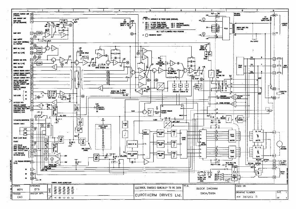


7 - 1
7.0 BASIC SETTING UP AND OPERATING INSTRUCTIONS
7.1 PRESET ADJUSTMENT DESCRIPTION
Check the preset potentiometer settings on the larger plug-in card which is accessible under the front cover. Thepotentiometers are normally factory set to positions which will provide adequate performance in mostload/controller configurations. It is recommended that initially the presets are left in these positions and that finetuning of the system is done, if necessary, at the end of the commissioning process.
The one exception to this is the main current limit preset; note the setting of this control and then turn it fullyanticlockwise. The initial setting of the presets should thus be as follows:
POT No. DESCRIPTION NORMAL INITIALSETTING
1 Setpoint ramp up rateClockwise rotation gives more rapid acceleration.
Midway
2 Setpoint ramp down rateClockwise rotation gives more rapid deceleration.
Midway
3 Zero speedIt should not be necessary to adjust this initially on anew factory tested drive.
About midway
4 Standstill thresholdSets low speed drive quench level if the standstill logic switch S8/2is set to the on position .Clockwise sets lower speed.
Midway
5 Speed ProportionalClockwise increases speed loop gain
20%Clockwise
6 Speed IntegralClockwise decreases speed loop integral time constant.
20%Clockwise
7 Main Current LimitClockwise increases current limit up to max. 200%FLC* short-term overload.
Fully anti-clockwise(Zero current)
8 Current ProportionalClockwise increase current loop gain.
Midway
9 Current IntegralClockwise decreases current loop integral time constant.
Fully anti-clockwise
10 Speed CalibrationClockwise increases motor speed.
About midway
11 FieldField Voltage O/P clockwise increases output voltage (see S9/4)
Fully anti-clockwise

7 - 2
7.2 OPTION SWITCHES
There are two user selectable option switches S8 and S9, which are located under the lower flap of the controlboard. Selection should only be made when the controller is isolated.
S8/1 BUFFERED CURRENT SIGNAL (terminal 27)UP = ON = Armature current meter reads ± Amps. For applications employing a centre-zero meter.DOWN = OFF = Meter reads modulus. For applications employing a uni-directional meter.DEFAULT:ONNOTE: In 546 and 548 units the Armature Current Meter will always read + Amps, regardless of the setting ofswitch S1, since these convertors cannot produce negative output current.
S8/2 STANDSTILL LOGICUP = ON = Standstill logic enabled. This will disable the drive whenever the Total Setpoint is zero and thespeed is below the standstill threshold set by P4.DOWN = OFF = Standstill logic inoperative.DEFAULT:OFF
S8/3 SETPOINT RAMP CONNECTIONUP = ON = Setpoint Ramp Output internally summed with Input No. 1 and Input No. 2.DOWN = OFF = Setpoint Ramp Output internally disconnected from the summing amplifier (but still availableat terminal 8).DEFAULT:ON
S8/4 SETPOINT RAMP RANGEUP = ON = Setpoint ramp rate adjustable from 0.25 to 7.5 seconds.DOWN = OFF = Setpoint ramp rate adjustable from 2.5 to 75 seconds.DEFAULT:OFF
S8/5 HEALTH LATCH ENABLEUP = ON = Prevents drive restart when fault condition removed (eg, on over-current reset, or motor thermistorreset, drive will not automatically restart) To allow drive to restart, terminal 34 (start) must be taken low (eg,0V).DOWN = OFF = Drive restarts automatically on fault reset.DEFAULT:ON
S8/6 EXTERNAL RAMP RESETUP = ON = Setpoint ramp reset by either drive quench or terminal 6 to 0V.DOWN = OFF = Setpoint ramp reset only by terminal 6 to 0V (allows external use of setpoint ramp).DEFAULT: ON
S8/7 CONTACTOR DROP OUT ON OVER- CURRENTUP = ON = Contactor does not drop out on over-current trip (this can prevent burning of contactor poles incertain configurations).DOWN = OFF = Contactor drops out on over-current.DEFAULT: OFF
S8/8 TACH FILTER (10ms time constant)UP = ON = Tach filter of 10ms time constant applied to the speed feedback to attempt to remove tach ripple.Note that this option will have a destabilising effect on the speed loop stability and a reduction in speed loopgain P5, may be required.DOWN = OFF = No tach filter.DEFAULT: OFF
S9/1 HALF WAVE FIELD SUPPLYUP = ON = Half wave rectification field supply. Typically using 415V single phase supply the field voltage willbe 180V DC nominal.*DOWN = OFF = No field supply from this option.DEFAULT: OFF
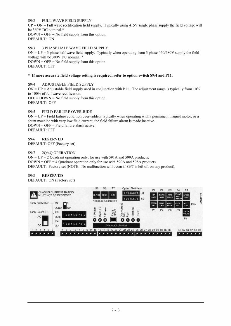
7 - 3
S9/2 FULL WAVE FIELD SUPPLYUP = ON = Full wave rectification field supply. Typically using 415V single phase supply the field voltage willbe 360V DC nominal.*DOWN = OFF = No field supply from this option.DEFAULT: ON
S9/3 3 PHASE HALF WAVE FIELD SUPPLYON = UP = 3 phase half wave field supply. Typically when operating from 3 phase 460/480V supply the fieldvoltage will be 300V DC nominal.*DOWN = OFF = No field supply from this optionDEFAULT: OFF
* If more accurate field voltage setting is required, refer to option switch S9/4 and P11.
S9/4 ADJUSTABLE FIELD SUPPLYON = UP = Adjustable field supply used in conjunction with P11. The adjustment range is typically from 10%to 100% of full wave rectification.OFF = DOWN = No field supply form this option.DEFAULT: OFF
S9/5 FIELD FAILURE OVER-RIDEON = UP = Field failure condition over-ridden, typically when operating with a permanent magnet motor, or ashunt machine with very low field current, the field failure alarm is made inactive.DOWN = OFF = Field failure alarm active.DEFAULT: OFF
S9/6 RESERVEDDEFAULT: OFF (Factory set)
S9/7 2Q/4Q OPERATIONON = UP = 2 Quadrant operation only, for use with 591A and 599A products.DOWN = OFF = 4 Quadrant operation only for use with 590A and 598A products.DEFAULT: Factory set (NOTE: No malfunction will occur if S9/7 is left off on any product).
S9/8 RESERVEDDEFAULT: ON (Factory set)

7 - 4
7.3 CALIBRATION
THE CONTROLLER IS NOT PRE-CALIBRATED TO ORDER DURING MANUFACTURING,HENCE IT IS THE RESPONSIBILITY OF THE USER TO ENSURE THAT THE CORRECTCALIBRATION PROCEDURE HAS BEEN FOLLOWED.
NOTE: DO NOT ADJUST THE CALIBRATION SWITCHES WHEN THE DRIVE ISOPERATIONAL.
7.3.1 SPEED CALIBRATION
Select the source for tach feedback using switch S1 (refer to description for S1).
Adjust calibration switches: S2 0 / 100 VoltsS3 0 - 90 VoltsS4 0 - 9 Volts
to obtain the tach feedback voltage at full speed.
Check motor name plate for maximum speed, do not exceed this value.
For full speed tach voltages greater than 200 Volts an external resistor, value RE, is required in series with thetach.
When the maximum value is selected (ie, 199) then RE is approximately given by the formula,
RE = tach volts - 200 K ohms 5
The power dissipation of this resistor is given by the formula
PE = 5 (tach volts - 200) mW.
7.3.2 ARMATURE CURRENT CALIBRATION
Before calibration, check the motor name plate for the value of rated current.Ensure that the power chassis has the appropriate rating value.Do not exceed the motor name plate value, or the chassis rated value.Set the calibration switches to motor full load current minus 1 amp.
Use calibration switches: S5 0 - 700 AmpsS6 0 - 90 AmpsS7 0 - 9 Amps
NOTE: Settings above 720 are invalid. 598A and 599A are calibrated by burden resistors in the chassis.Calibration in these circumstances is set by the combined value of the burden resistors and S5,S6, and S7 shouldbe set to zero.
RB = 2200 ohmsFull Load Current
NOTE: Full load current = 100% rating
and 1 = 1 + 1 + 1 RB R1 R2 R3Values are selected in the factory on the basis of the best combination of standard resistor values.
NOTE: The armature current calibration switches should not be changed to increase the current above thefactory set value without consulting Eurotherm Drives Limited Engineering Department.

7 - 5
7.3.3 FIELD VOLTAGE CALIBRATION
Field voltage calibration is set by selection of the option switches S9/1/2/3/4 (see S9 description). When S9/4 isselected, the field voltage can be adjusted by preset P11. By using the selection of S9/4 and P11, the mostaccurate setting of field voltage can be achieved.
7.4 BEFORE ATTEMPTING TO CONNECT POWER
CAREFULLY CHECK
1. Auxiliary power supply voltage is correct.
2. Main power supply voltage is correct.
3. Armature voltage and current ratings.
4. Field option, voltage and current rating.
5. All external wiring circuits -Power connectionsControl connectionsMotor connections
6. For damage to equipment or wiring.
7. For loose ends, clippings, drilling chips, etc, lodged in the drive or electrical equipment.
8. Inspect the motor, in particular the commutator for any extraneous matter. If an air line is available it isrecommended to blow over the commutator.
9. Check that the brushes are properly seated and that the brush spring tensions are adequate. If possible checkthat the motor (and vent fan motor when fitted) can be turned freely by hand.
ENSURE:
1. That rotation of the machinery in either direction will not cause a hazard.
2. That nobody else is working in another part of the equipment that can be affected by powering up.
3. That other equipment will not be adversely affected by powering up.
7.5 PREPARATION
1. Prevent the Main 3-phase power supply and single phase auxiliary supply from becoming connected to thedrive by removing the main external HRC fuses.
2. Disconnect the load from the motor shaft if possible.
3. If there is any doubt about the integrity of a particular installation, insert a high wattage resistor ie, fireelements, in series with the motor armature.
4. Check that the calibration has been satisfactorily implemented and is suitable for the DC machine to which itis connected. Refer to section 7.3.
5. Check the preset potentiometer settings on the larger plug-in card which is accessibleunder the front cover. The potentiometers are normally factory set to positions which will provide adequateperformance in most load/controller configurations. It is recommended that initially the presets are left in thesepositions and that fine tuning of the system is done, if necessary at the end of the commissioning process.

7 - 6
Refer to Section 7.1
The one exception to this is the main current limit preset; note the setting of this control and then turn it fullyanticlockwise. Refer to section 7.1.
6. Set option switches.
Refer to section 7.2
7. Plug a Diagnostic Test Unit type 5570 into the socket on the control printed circuit board, observing correctorientation of the connector (see Diagnostic Test Facility, section 8.3). This unit is not essential to the successfulcommissioning of a drive, but it very much simplifies the procedure and can save a considerable amount of time.
7.6 CHECKING THE DRIVE AND SETTING UP
1. When all the preceding steps are completed the auxiliary power supply can be connected to terminals D7 andD8 (but do not connect the Main 3-phase power supply at this stage). Immediately check that the correct voltageappears between D7 and D8.
2. Now check:i) The drive condition indicators - these are seven LED lamps at the lower right-hand corner of the Main Controlprinted circuit board. LED No's 1, 4 and 7 should be on.
ii) Check the +24V (nominal) supply at terminal 38 (with respect to 0V) .
iii) If a Diagnostic Test Unit (5570) is available, check the ±15V supplies at switch positions 1 and 4.
iv) Check the +10V supply rail: Switch to diagnostic test point 2 or measure the voltage between terminals14 (+10V) and (0V).
v) Check the -10V supply rail: Switch to diagnostic test point 3 or measure the voltage between terminals 15 (-10V) and (0V).
3 .If a Diagnostic Test Unit is available, check that all other test point readings are as shown in Diagnostic Chart,SECTION 8.5.3
4. Check that a speed demand signal is available. This will normally appear as an input to the Setpoint Ramp onterminal 7 (diagnostic test point 11)Additional setpoint inputs may also appear at:Input No 1 (+), terminal 9 (Diag. 12)Input No 2 (+), terminal 10 (Diag 13)Input No 3 (-), terminal 11 (Diag 14)NOTE: The sum of the setpoint voltages appears at terminal 13 (Diagnostic 15) as the Total Setpoint voltage.
5. If possible, check the polarity of the tach signal by rotating the motor shaftmanually in the "forward" direction (ie, the direction which should correspond to a positive setpoint at terminal7:The voltage at terminal 3 (or 26) should go positive.(when using a dc tach)The voltage at Diagnostic test point 16 should go negative.(when using a dc or ac tach)
6. Press the "Drive Start" pushbutton or otherwise initiate START:The Main 3-phase contactor should pull in and latch via the control relay with the drive.Press the "Drive Stop" pushbutton or otherwise initiate STOP:The main contactor should drop out, de-energised. If not disconnect all power supplies and check the Stop/Startcircuit and contactor wiring.NOTE: The main contactor should NEVER be operated by any means other than the drive internal contactorcontrol circuit as shown in the wiring diagram HJ387211D.

7 - 7
WARNING: DO NOT PROCEED FURTHER UNLESS THE STOP/START CIRCUITS ANDCONTACTOR OPERATE CORRECTLY.
7. Turn off all power supplies to the equipment and when the whole system is totally isolated and safe, reconnectthe Main 3-phase power supply.
8. Turn on Auxiliary single phase supply.
9. Turn on Main 3-phase supply.
10. Turn the Speed Setpoints to zero so that the Total Setpoint voltage is zero ,terminal 13, Diagnostic 15.
11. Check that the Main Current Limit preset (P7) is set to zero (fully anticlockwise).
12. Initiate "Drive Start" and immediately check that the correct field voltage appears betweenterminals D3 and D4. Note that this will be high voltage DC, so proceed with extreme caution. Do not continueif this is not correct, but switch off all supplies and recheck the Calibration and Option SwitchesCheck that the motor ventilation fan, if fitted, is rotating in the correct direction. Check the direction visually asthe fan starts since a centrifugal fan may produce considerable air flow even when rotating in the wrongdirection.
13. Check that all Drive Condition Indicators except LED 6 are lit. Refer to the Diagnosticsection 8.4 for explanation of the LED functions. In particular note that any exterior interlocks in the Enable andAuxiliary Enable circuits will affect the conditions of LED's 5 and 7.
14. Check that the Standstill Logic is switched OFF (Option Switch S8/2).NOTE:a) During the following stages (15 and 16) be ready to stop the drive immediately should the motor try tooverspeed.b) Before altering any connections make sure that all Auxiliary and Main power supplies are totally isolatedfrom the drive and equipment and that the motor is stationary.
15. Adjust the Speed Setpoint so that the Total Setpoint voltage is about 0.5 volts (terminal 13,Diagnostic 15).Slowly increase the Main Current Limit setting up to about 20% FLC (ie, not more than 1 volt at Diagnostic testposition 24). Since the Total Setpoint is set to 0.5V the motor speed should increase to only 5% of full speed. Ifthis speed is exceeded, reversed connection of the tach or field is implied, quickly turn the Main Current Limit(P7) to zero (anticlockwise).
Disconnect all supplies and reverse either the field or tacho connections, then reconnect the supplies and repeatthe test. If the motor still runs out of control check the tacho and the continuity of its wiring. PROCEEDONLY WHEN THIS TEST IS SATISFACTORILY COMPLETED.
16. With the Main Current Limit (P7) set to about 20% FLC slowly increase the Total Setpointvoltage to +1 volt (terminal 13, Diagnostic 15). The motor should now run at about 10% Full Speed and LED 6should light.NOTE:When correctly connected and operating normally at constant speed the Speed Feedback voltage (Diagnostic 16)will be equal to the Total Setpoint voltage (Diagnostic 15) but of opposite polarity. Under these conditions theSpeed Error voltage (Diagnostic 17) will be zero. If this condition cannot be achieved, the system is probably incurrent limit (this is most likely at this stage if the load is coupled to the motor). Increase the setting of the MainCurrent Limit (P7) slowly until motor accelerates to the set speed and the Speed Error signal falls to zero.
17. Check the motor direction; if it is incorrect disconnect all supplies and reverse both tach and fieldconnections.
18. 590A and 598A drives only:Adjust the Total Setpoint voltage to about -1V and check that the motor runs in control in the reverse direction.

7 - 8
19a. 590A and 598A drives:Set the Speed Setpoint to zero and adjust the Speed Zero preset potentiometer (P3) for minimum shaft creep(Alternatively the Speed Zero potentiometer may be used to adjust the balance of maximum speed in forwardand reverse directions).
19b. 591A and 599A drives: Set the Speed Setpoint to zero. Turn the Speed Zero preset potentiometer (P3) clockwise until the motor shaftturns, then back-off P3 until the shaft just stops turning.
20. Gradually increase the Speed Setpoint to maximum and check that the shaft speed is nominally correct. Iffine adjustment of the top speed is required, the Maximum Speed potentiometer (P10) provides ±10% trim.NOTE:If the load is connected to the motor it may be necessary to increase the Main Current Limit control (P7) settingto achieve full speed.
21. 590A and 598A drives only:Reverse the Speed Setpoint and check the maximum reverse speed.
22. Reset the Main Current Limit (P7) to its original position, which was noted in part 7.1 of this procedure. Ifin doubt set the control (P7) to 60% clockwise rotation (6V measured at Diagnostic 24) corresponding to amaximum armature current of 1.2 times Full Load. Fully clockwise rotation of P7 (10V measured at Diagnostic24) corresponds to an armature current level of twice full load.Note that if the drive runs into an overload condition, the current is automatically reduced on an inverse timecharacteristic back to 110% of full load. If the overload facility is not required, the Main Current Limitpotentiometer (P7) should be turned progressively anticlockwise, almost to the midway position - this will limitthe current to just above Full Load.
7.7 RUNNING PERFORMANCE ADJUSTMENTS
1. Disconnect all supplies and connect the motor to its load. Set the speed setpoint to zero, reconnect thesupplies and switch on.Increase the speed setpoint and check that the drive runs smoothly under load; the speedshould be stable and the armature current should be steady.The Proportional and Integral potentiometers (P5, P6, P8 and P9), as preset by Eurotherm Drives Limited, willprovide stable and responsive performance under most load conditions. Thus if instability is observed it isimportant to first check the load and couplings:If there is a cyclic variation of the armature current check the mechanical couplings to the load - this is acommon cause of apparent instability in either the speed or motor current. If speed instability is present checkwhether the repetition rate of the instability is related to any of the mechanical revolution rates of the load - if itis the instability frequency will vary with speed. This form of instability may be reduced by adjustment of thedrive presets, but total elimination of the problem may require improvement of the load characteristics.
2. Instability due to incorrect setting of the drive control parameters can occur and is recognisable because itsfrequency will be relatively independent of the drive speed. If this form of instability is present, or if theapplication demands that the drive is trimmed for optimum response, then the stability controls may be adjustedas follows. Note that while the speed stability and response may be improved without the use of a DiagnosticUnit or Oscilloscope it is difficult to optimise the current response without such instrumentation. Consequently,the following procedure assumes that both instruments are available.
3. Current Loop Adjustment (P8 and P9)With all power supplies disconnected, disconnect the field wires from terminals D3 and D4, labelling each wireclearly so that it can later be reconnected with the correct polarity. Ensure that option switch is in the ONposition (to override the field fail alarm )
NOTE:i. It is now possible to operate the drive in a stalled condition. Great care must be taken not to damage the motorby overheating. If the motor is fitted with a force ventilation fan arrange that it is connected and running duringthe test. In any case DO NOT remain in the stalled condition for long periods.ii. Although the field supply is disconnected the motor may still produce some torque due to residual orcompound field flux. It is essential therefore, to mechanically lock the motor shaft, or apply sufficient load toprevent rotation during the following procedure.

7 - 9
4. To achieve Full Load Current it is necessary to override the Tach Failure Alarm/Clamp:Disconnect the Tach (+) wire from terminal 3 and then link terminal 3 to ±10V (terminal 14, 15, or 24).
5. The optimum setting of the Current Proportional and Integral presets (P8 and P9) depends, to some extent, onthe setting of the Main Current Limit (P7). Thus P7 should be correctly adjusted to suit the load, beforeadjustment of P8 and P9 is attempted.
6. When the Main Current Limit control is correctly set, proceed as follows:If the Speed Setpoint is applied via the Setpoint Ramp, set the Ramp Rate presets P1 and P2 fully clockwise andOption Switch S8/4 UP (ON), to provide the fastest ramp rate. Set the Speed Proportional and Integral presets(P5 and P6) fully clockwise to provide the fastest rate of change of Current Demand signal (observable atDiagnostic 25).Connect the Diagnostic Unit to the Control printed circuit board (accessed via the outer cover - observe correctorientation of plug into the socket). Connect the Oscilloscope to the output sockets on the Diagnostic Unit andswitch to Diagnostic 26. This provides access to a safe, isolated signal representing the armature currentwaveform where ±1.1V = ±100% full load current.
7a. 590A and 598A drives:Reconnect the supplies and switch on. Observe the armature current waveform while changing the polarity ofthe Current Demand signal (by varying the Speed Setpoint). With each change of Current Demand polarity thecurrent should increase rapidly, but without overshoot and then remain steady. If necessary adjust P8 and P9slowly to obtain a Critically Damped performance, ie the fastest response possible without overshoot, as shownin Figure 3.Figures 1 and 2 show typical armature current waveforms where P8 and P9 are incorrectly set and indicate theadjustment required to improve the drive performance, to conform with that of Figure 3.In general, clockwise rotation of the presets will improve the speed of response, but rotating the controls too farwill tend to introduce overshoot.
7b. 591A and 599A drives:Reconnect the supplies and switch on. While observing the armature current waveform, suddenly increase theCurrent Demand Signal by rapidly increasing the Speed Setpoint from zero to +10V (then reduce the Setpoint tozero again; note that the armature current will return more rapidly to zero if the Speed Zero preset is setanticlockwise). With each increase of Current Demand the current should increase rapidly, but withoutovershoot and then remain steady. If necessary adjust P8 and P9 slowly to obtain a Critically Dampedperformance, ie the fastest response possible without overshoot, as shown in Figure 3.*Figures 1* and 2* show typical armature current waveforms where P8 and P9 are incorrectly set and indicate theadjustment required to improve the drive performance, to conform with that of Figure 3*.In general, clockwise rotation of the presets will improve the speed of response, but rotating the controls too farwill tend to introduce overshoot.* Note that in 591A and 599A non-regenerative drives the current waveform will increase from zero instead ofthe negative value shown in the figures.


7 - 11
8. When the Current Loop response adjustment is completed, switch off the drive anddisconnect all supplies.
REMOVE THE LINK FROM BETWEEN TERMINAL 3 AND THE 10V SUPPLY AND THENRECONNECT THE TACHO (+) WIRE TO TERMINAL 3.
Return S9/5 back to its original position and reconnect the field wires to terminals D3 and D4, ensuring that theyare replaced in their original positions, ie with correct polarity. Remove any mechanical devices previously usedto lock the motor shaft.
9. Speed Loop Adjustment (P5 and P6)If the Speed Setpoint is applied via the setpoint ramp turn P1 and P2 fully clockwise and switch S8/4 UP (ON).Set the Speed Setpoint to zero. Switch the Diagnostic Unit to position 16 so that the Oscilloscope displays thescaled Tacho Feedback signal (±10V = ± full speed).
10. Reconnect the supplies and initiate Start. Apply a small step change (about 20%) to theSpeed Setpoint input and observe the speed response. If necessary adjust the Speed Proportional and SpeedIntegral presets (P5 and P6) gradually to obtain a Critically Damped performance, ie the fastest responsepossible without overshoot, as shown in Figure 4, Curve (c). In general, clockwise rotation of the presets willimprove the rate of response, but advancing the controls too far will tend to introduce overshoot. The optimumsetting of P5 and P6 will be a compromise between the two extremes shown in Curves (a) and (b), Figure 4.
11. When the Speed Loop adjustment is completed reset Option Switch S8/4 to its original position.
12. If the Speed Setpoint is applied via the Setpoint Ramp, then the acceleration and decelerationrates of the drive, in response to a change of input, are individually adjustable by the Positive and Negative Ratepresets, P1 and P2. The fastest rates are achieved by setting the controls fully clockwise. The range of thepotentiometers can be selected by Option Switch S8/4 to be either 0.25 to 7.5 seconds, or 2.5 to 75 seconds toFull Speed.
13. Reset Option Switch S8/2 (Standstill Logic) to its original position. Note that if it is desiredto eliminate shaft creep at zero setpoint in 590A and 598A regenerative drives then this switch should be set tothe UP (ON) position. This provides a "deadband" about zero speed which is adjustable by the StandstillThreshold preset (P4) over the range ±0.5 to ±4% of Full Speed. The armature current will be totally interruptedwhen the shaft speed is within the band set by P4 and the Total Setpoint voltage is zero, at any other time thedrive will operate normally.NOTE:The setting of the Zero Speed preset P3 will effect the symmetry of operation of the Standstill Logic about zero.
14. The drive should now be ready to operate. It is now essential to check the remaining controlcircuitry for correct operation. In particular, check that all Emergency Stop buttons and external interlocks workefficiently.


8 - 1
8. DIAGNOSTIC TEST FACILITY
8.1 DESCRIPTION OF DIAGNOSTIC TEST UNIT
The drive is fitted with a multi-pin socket near the lower edge of the Main Control printed circuit board to allowconnection of a type 5570 Diagnostic Test Unit.The Diagnostic Test Unit is small, portable, plug-in module which when connected to the drive provides accessvia a selector switch to 27 internal test points. The unit incorporates the following features.1. A digital voltmeter to permit accurate measurement of steady state signals.2. An analog voltage "Trend Indicator" in the form of a row of LED displays which span signal levels in therange ±10V. This is a fast responding indicator which shows the magnitude of rapidly changing signals.3. A pair of output sockets (standard 4mm) to enable signals to be monitored externally on an oscilloscope.
Under normal operating conditions, all signals which appear on the Diagnostic Test Unit are isolated from themain power supplies and field and armature circuits.
8.2 DIAGNOSTIC TEST PROCEDURE
The Diagnostic Test Unit should always be used in conjunction with the drive condition indicators located on themain control printed circuit board.In attempting to determine causes of fault conditions it is essential to follow the normal setting up procedure forthe drive as set out in the appropriate sections of this manual.If you reach a stage in the set-up procedure where the required conditions are not satisfied:
FIRSTLook at the DRIVE CONDITION INDICATORS and refer to the Indicator Description Chart ( Section 8.4).SECONDLook at the DRIVE CONDITION INDICATORS and compare with the Status Recognition Chart (Section 8.5.1and 8.5.2).THIRDCheck the voltage indicated by the 5570 DIAGNOSTIC TEST UNIT and compare with the VoltageMeasurement Chart (Section 8.5.3).
8.3 CONNECTION AND DISCONNECTION OF THE DIAGNOSTIC TEST UNIT
CONNECTION:1. Disconnect the Auxiliary and Power Supplies from the drive.2. Insert the Diagnostic Unit Plug into the Socket, ensuring that Polarising Tab and Slot are
correctly aligned.
DISCONNECTION:1. Disconnect the Auxiliary and Power Supplies from the drive.2. Remove Diagnostic Unit Plug.
8.4 DRIVE CONDITION INDICATORS - DESCRIPTION
LED1: 1 PHASE (AUXILIARY SUPPLY) ON/OFFON: Single phase auxiliary supply on.OFF: a) Single phase supply or fuse FS1 failed.
b) Preset PCB not fitted or plugged in correctly.
LED2: 45-65HZ ENABLE/INHIBITON: Phase locked loop synchronised.OFF: Phase locked loop not synchronised to main 3-phase power supply.

8 - 2
LED3: 3-PHASE POWER SUPPLYON: 3-Phase power supply connected.OFF: a) 1 Phase or more not connected.
b) Main contactor not closed.c) Main fuse failure check .d) Coding fuse failure check FS2, FS3, FS4.
LED4: NORMAL/OVER CURRENT FAULTON: Armature Current Normal.OFF: Armature Current has exceeded 300% full load. In this condition the main contactor will beautomatically tripped. See Option Switch S8/5 and S8/7 .The entire system must be checked thoroughly toascertain the cause of the failure. The drive can be restarted after such a fault by either pressing the "FAULTRESET" pushbutton or externally by applying +24V (from terminal 38) to terminal 39 and removing the startinput.
LED5: RUN/INHIBITON: Indicates that both "READY" signal (on terminal 35) and "ENABLE" signal (on terminal 32 anddiagnostic 5) are present. The drive will now start.OFF: Either "READY" or "ENABLE" signals have been removed.NOTES:a) The "READY" signal depend upon each of the following signals being in its enabled condition:
i) Single phase (auxiliary supply) On/Off (LED1).ii) 45-65HZ Enable/Inhibit (LED2).iii) 3-Phase (Main Supply) On/Off (LED3).iv) Overcurrent trip (LED4).v) Motor Thermistor/Microtherm (DIAGNOSTIC 6).vi) Field Fail (DIAGNOSTIC 7).vii) Auxiliary Enable (DIAGNOSTIC 8).viii) Start Instruction (DIAGNOSTIC 9).
b) The "ENABLE" signal depends on the external connection of +24V (Nominal) to Enable terminal32, normally from START SUPPLY terminal 31.
LED6: ROTATING/STANDSTILLON: Indicates the motor shaft is rotating. (Speed signal exceeds STANDSTILL THRESHOLD set bypotentiometer P4. Adjustment range 0.5 to 4%).OFF: Motor shaft speed is less than standstill threshold.
LED7: HEALTHON: Drive Health normal.OFF: Drive in fault condition.NOTES:a) In the STOP condition the "HEALTH" signal only requires that the internal supply rails are present.b) In the START condition the "HEALTH signal requires the READY signal (terminal 35) to be
present.

8 - 3
8.5 DRIVE CONDITION INDICATORS STATUS RECOGNITION
8.5.1. STOP CONDITION
CONDITION REFERENCE STOP CONDITION1 PHASE (AUX) ON/OFF
45-65HZ ENABLE/INHIBIT � LED ON3-PHASE (MAINS) ON/OFF � LED OFF
NORMAL/OVERCURRENT FAULT ⊗ EITHERRUN/INHIBIT
ROTATING/STANDSTILLNORMAL/ALARM
1 2 3 4 5 6 7 CONDITIONS/CHECKS
A � � � � � � � NORMAL STOP CONDITION
B � � � � � � � NO AUXILIARY SUPPLYCHECK:1. Auxiliary AC. supply voltage on terminal D9 with respect to terminal D102. Auxiliary supply fuse F1.
C � � � � � � � PRESET BOARD NOT FITTED.CHECK:1. Preset board inserted correctly.
E � � � � � � � DRIVE INCORRECTLY INDICATES SHAFT ROTATING.CHECK:1. Speed feedback signal (diagnostic 16).2. Voltage on terminal 3 with respect to terminal 43. Voltage on terminal 2 with respect to terminal 14. Preset board potentiometer P10.

8 - 4
8.5.2 START CONDITION
CONDITION REFERENCE START CONDITION1 PHASE (AUX) ON/OFF
45-65HZ ENABLE/INHIBIT � LED ON3-PHASE (MAINS) ON/OFF � LED OFF
NORMAL/OVERCURRENT FAULT ⊗ EITHERRUN/INHIBIT
ROTATING/STANDSTILLNORMAL/ALARM
1 2 3 4 5 6 7 CONDITIONS/CHECKS
A � � � � � � � NORMAL STOP CONDITION
F � � � � � ⊗ � NORMAL RUN CONDITION
G � � � � � � � DRIVE REMAINS IN STOP CONDITION. STATUS LEDS DONOT CHANGE WHEN START BUTTON PRESSED.CHECK:1. Drive is receiving Start Instruction (Diagnostic 9).2. Continuity of stop line terminals 31 to 33.3. Continuity of start line terminals 33 to 34.
H � � � � � � � ALARM CONDITION - START INSTRUCTION PRESENT BUTDRIVE NOT RECEIVING 3-PHASE.CHECK:*1. Main contactor is pulled in.2. Contactor coil connections (terminals D11 and D12).3. Coil voltage is correct.4. Coil resistance i.e. not open circuit.5. All three phases present on drive input terminals L1, L2 and L3. WARNING! High voltages appear on these terminals.6. Fuses F2, F3, and F4. WARNING! Isolate Drive from supply before checking.
I � � � � � � � ALARM CONDITION - SPECIAL CASE OF ABOVE ONE PHASEONLY MISSING.CHECK:*Items 5 and 6 in H above.
J � � � � � � � NORMAL RUN CONDITION - SHAFT ROTATING
K � � � � � � � DRIVE INHIBITED BY 'ENABLE' SIGNAL AT 32.CHECK:1. Drive enable (diagnostic 5).2. Continuity between terminal 32 and start supply 31 or 32 and +24V (Nominal) supply 38, as appropriate.

8 - 5
8.5.2 START CONDITIONContinued...CONDITION REFERENCE START CONDITION
1 PHASE (AUX) ON/OFF45-65HZ ENABLE/INHIBIT � LED ON
3-PHASE (MAINS) ON/OFF � LED OFFNORMAL/OVERCURRENT FAULT ⊗ EITHER
RUN/INHIBITROTATING/STANDSTILL
NORMAL/ALARM1 2 3 4 5 6 CONDITIONS/CHECKS
L � � � � � � � NORMAL RUN CONDITION - SHAFT STATIONARYIF INCREASING SETPOINT HAS NO EFFECT THEN:FOR SPEED CONTROL MODECHECK:1. Total Setpoint (diagnostic 15) is responding to the setpoint input.2. That the total Setpoint is positive in 591A units.3. Main current limited (diagnostic 24) is not at zero.4. Auxiliary current limits (diagnostics 22 and 23) are not at zero.5. That the current demand is not isolated (diagnostic 19).6. Motor armature connections (with supplies isolated).7. Tacho connections correct diagnostics 15 and 16).8. Motor not stalled. Diagnostic 26 indicates armature current.
FOR TORQUE (CURRENT) CONTROL ONLYCHECK:
Items 2, 3, 5, 7 and
8. Auxiliary current input (diagnostic 20) is not at zero.9. Auxiliary current input is selected (diagnostic 21).
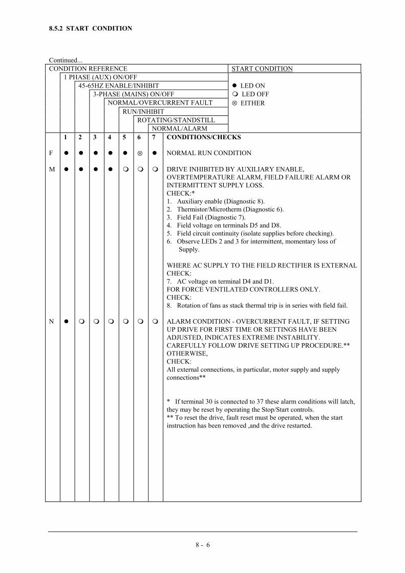
8 - 6
8.5.2 START CONDITION
Continued...CONDITION REFERENCE START CONDITION
1 PHASE (AUX) ON/OFF45-65HZ ENABLE/INHIBIT � LED ON
3-PHASE (MAINS) ON/OFF � LED OFFNORMAL/OVERCURRENT FAULT ⊗ EITHER
RUN/INHIBITROTATING/STANDSTILL
NORMAL/ALARM1 2 3 4 5 6 7 CONDITIONS/CHECKS
F � � � � � ⊗ � NORMAL RUN CONDITION
M � � � � � � � DRIVE INHIBITED BY AUXILIARY ENABLE,OVERTEMPERATURE ALARM, FIELD FAILURE ALARM ORINTERMITTENT SUPPLY LOSS.CHECK:*1. Auxiliary enable (Diagnostic 8).2. Thermistor/Microtherm (Diagnostic 6).3. Field Fail (Diagnostic 7).4. Field voltage on terminals D5 and D8.5. Field circuit continuity (isolate supplies before checking).6. Observe LEDs 2 and 3 for intermittent, momentary loss of Supply.
WHERE AC SUPPLY TO THE FIELD RECTIFIER IS EXTERNALCHECK:7. AC voltage on terminal D4 and D1.FOR FORCE VENTILATED CONTROLLERS ONLY.CHECK:8. Rotation of fans as stack thermal trip is in series with field fail.
N � � � � � � � ALARM CONDITION - OVERCURRENT FAULT, IF SETTINGUP DRIVE FOR FIRST TIME OR SETTINGS HAVE BEENADJUSTED, INDICATES EXTREME INSTABILITY.CAREFULLY FOLLOW DRIVE SETTING UP PROCEDURE.**OTHERWISE,CHECK:All external connections, in particular, motor supply and supplyconnections**
* If terminal 30 is connected to 37 these alarm conditions will latch,they may be reset by operating the Stop/Start controls.** To reset the drive, fault reset must be operated, when the startinstruction has been removed ,and the drive restarted.

8 - 7
8.5.3 DIAGNOSTIC TEST UNIT - VOLTAGE MEASUREMENTS
TESTNO.
DIAGNOSTIC TEST POINT DESCRIPTION CONDITION VOLTAGE
1 INTERNAL +15V SUPPLY Aux. Power ON +15V ±0.25VMax. 100Hzripple=25mVpeak to peak
2 EXTERNAL +10V SUPPLYNote: These supplies are buffered from internalreference supplies and have a maximum outputcurrent capability of 5mA.
Aux. Power ON +10V ±0.1VMax. 100Hzripple=5mVpeak to peak
3 EXTERNAL -10V SUPPLYNote:These supplies are buffered from internalreference supplies and have a maximum outputcurrent capability of 5mA.
Aux. Power ON -10V ±0.1VMax. 100Hzripple=5mVpeak to peak
4 INTERNAL -15V SUPPLY Aux.Power ON -15V ±0.25VMax. 100Hzripple=25mVpeak to peak
5 DRIVE ENABLEEnable = +24V(Nominal) on terminal 32Inhibit = open circuit to terminal 32
EnableInhibit
+15V 0V
6 MOTOR THERMISTOR/MICROTHERM Motor temperature correctMotor over temperature
+15V 0V
7 FIELD FAILNotes:1. This signal is interlocked with the internaltemperature sensor (force ventilated units only)and the internal ACCT connectors.
2. Internally supplied field will normally excitewhen the 3-phase power is connected to the drivei.e. only in the run condition, with the maincontactor energised.
3. Excitation of externally controlled field willdepend on the application.
4. Permanent magnet motor, field weakeningand remote field supply applications will employfield failure override. This will provide aconstant 'field normal' signal.
Field AND Interlocks Nominal
Field OR Interlocks Fail
+15V
0V
8 AUXILIARY ENABLEEnable = +24V (Nominal) on terminal 30Inhibit = Open circuit to terminal 30
EnableInhibit
+15V 0V
9 START INSTRUCTION START=+24V STOP = 0V
RunStop
+15V 0V

8 - 8
8.5.3 DIAGNOSTIC TEST UNIT - VOLTAGE MEASUREMENTS
TESTNO.
DIAGNOSTIC TEST POINT DESCRIPTION CONDITION VOLTAGE
10 SETPOINT RAMP RESET (SEE S8/6)Enable = Open circuit to terminal 6Reset to Zero = Connect terminal 6 to 0V
Ramp Enable AND RunRamp Reset OR Stop
+15V 0V
11 SETPOINT RAMP INPUTConnects directly to terminal 7 and measures theincoming speed demand signal.If terminal 7 is not used the voltage measuredshould be zero.
Variable Input:
100% forward speed demandZero speed or terminal 7 not used100% reverse speed demand*
+10V 0V -10V
12 INPUT NO 1Connects directly to terminal 9 and measures theincoming speed demand signal.If terminal 9 is not used the voltage measuredshould be zero.
Variable Input:
100% forward speed demandZero speed or terminal 9 not used100% reverse speed demand*
+10V 0V -10V
13 INPUT NO 2Connects directly to terminal 10 and measuresthe incoming speed demand signal.If terminal 10 is not used the voltage measuredshould be zero.
Variable Input:
100% forward speed demandZero speed or terminal 10 not used100% reverse speed demand*
+10V0V-10V
14 INPUT NO 3Connects directly to terminal 12 and measuresthe incoming speed demand signal.If terminal 12 is not used the voltage measuredshould be zero.Note: That input No 3 is of the opposite sense toall other speed inputs.
Variable Input:
100% forward speed demandZero speed or terminal 12 not used100% reverse speed demand*
-10V 0V+10V
15 TOTAL SETPOINTThis is the sum of all the speed demand signals,i.e. Input No 1, plus Input No 2, plus SetpointRamp Input (if S8/3 is closed), minus Input No3.It is clamped to a maximum output of ±11V.
Variable Signal:
100% forward speed demandZero speed100% reverse speed demand
+10V 0V-10V
16 SPEED FEEDBACKThis is the scaled and buffered tachogeneratorspeed feedback signal (under steady stateconditions it should be of opposite polarity butequal in magnitude to the Total Setpointmeasured on diagnostic 15).
Variable Signal:
100% forward speedZero speed100% reverse speed
-10V 0V+10V
17 SPEED ERRORThis is of opposite polarity to the differencebetween the Total Setpoint and speed feedbackvoltages. The magnitude of this signal isdependent on the setting of the SpeedProportional Gain (P5) and includes any ZeroSpeed offset value.
Run - Variable SignalNormal Steady State value
Stop - Total Setpoint = 0V Total Setpoint ≠ 0V
up to ± 10VApprox 0V
0V ±0.2V up to ±10V
18 CURRENT DEMANDThis signal is held to zero except in the runcondition when it is released by Main SystemEnable.Main System Enable depends on the"Run/Inhibit" signal (LED 5) and on theStandstill Logic (if switch S8/2 is closed).
Run - Variable Signal -590A/598A -591A/599A
Stop - (or Standstill)
±10V0 to +10V
0V ±0.1V
*590A drives only

8 - 9
8.5.3 DIAGNOSTIC TEST UNIT - VOLTAGE MEASUREMENTS
TESTNO.
DIAGNOSTIC TEST POINT DESCRIPTION CONDITION VOLTAGE
19 CURRENT DEMAND ISOLATEConnects directly to terminal 18.Note:1. For speed control operation leave terminal18 open circuit.2. For current control operation connect terminal18 to 0 Volts.
Speed control
Current control
+15V
0V
20 AUXILIARY CURRENT INPUTConnects directly to terminal 20.
Only operational if selected (See Diagnostic 21).
Variable Input (if used):Positive Bridge current = 200%FLC*Zero Current
Negative Bridge current = 200%FLC* (590A/598A only)
* FLC = Full Load Current
+10V
0V
-10V
21 SELECT AUXILIARY INPUTConnects directly to terminal 21.Note:1. To select input connect terminal 21 to 0 Volts .2. To disconnect input leave terminal 21 open circuit.
Select Input
Disconnect Input
0V
+15V22 AUXILIARY CURRENT LIMIT (POSITIVE)
Connects directly to terminal 22.Note:1. This positive current limit only operates up to the limit set by the Main Current Limit preset (P7) at Diagnostic 24.2. If no special limit is required leave terminal 22 open circuit.
Terminal 22 open circuit.
Variable Input:Positive current limit = 200% FLC*Positive current limit zero
*FLC = Full Load Current
+12V ±2V
+10V0V
23 AUXILIARY CURRENT LIMIT (NEGATIVE)Connects directly to terminal 25.Note:1. This negative current limit only operates up to the limit set by the Main Current Limit preset (P7) at Diagnostic 24.2. If no special limit is required leave terminal 25 open circuit.3. IN ALL 591A/599A APPLICATIONS TERMINAL 25 MUST BE OPEN CIRCUIT.
Terminal 25 open Circuit (see note3).
Variable Input:Negative current limit = 200%FLC*Negative current limit zero
*FLC = Full Load Current
-12V ±2V
-10V0V

8 - 10
8.5.3 DIAGNOSTIC TEST UNIT - VOLTAGE MEASUREMENTS
TESTNO.
DIAGNOSTIC TEST POINT DESCRIPTION CONDITION VOLTAGE
24 MAIN CURRENT LIMITOverrides Auxiliary Current Limits(see Diagnostic 22 and 23).
Scaling: 0 to +10V equivalent to 0 to 200% Full Load Current (FLC).
Characteristics:i. When set between 0 and 5.5V (0 to 110% FLC*) the set current is available continuously.ii. When set between 5.5 and 10V (110 to 200% FLC*) the current is controlled by an overload inverse time characteristic. The absolute limit is fixed at the set value and the current is allowed to exceed 110% FLC* for a short time before it is automatically cut back to 110%. The time allowed is this over current region depends on the magnitude of the overload e.g. 150% load is permitted for approximately 30 seconds before cut back starts. 200% load is permitted for approximately 10 seconds before cut back starts.
Variable Voltage depending uponthe input to terminal 25 (normally+10V) and the setting of the MainCurrent Limit Potentiometer P7.
0 to +10V
25 TOTAL CURRENT DEMAND (INVERTED)This is the net current demand signal (inverted).It is limited by the current limit settings and theoverload inverse time characteristic.It is held to zero except in the run conditionwhen it is released by the Main System Enable.The Main System Enable depend on the"Run/Inhibit" signal (LED5) and on theStandstill logic (if switch S8/2 is closed).
Variable demand in run condition:Positive Bridge Current = 200%FLC*Zero Current.Negative Bridge Current = 200%FLC* (590A/598A only)In stop condition.* FLC = Full Load Current
-10V0V
+10V0V
26 CURRENT FEEDBACKMeasured armature current signal.
This is an isolated signal which is directlyproportional to the Armature Current.Under steady state condition it should be ofopposite polarity but reduced in magnitude to theTotal Current Demand signal at Diagnostic 25.
Variable signal in run condition:Positive Bridge Current = 200%FLC*Zero Current.Negative Bridge Current = 200%FLC* (590A only)
* FLC = Full Load Current
+2.2V0V
-2.2V

8 - 11
8.5.3 DIAGNOSTIC TEST UNIT - VOLTAGE MEASUREMENTS
TESTNO.
DIAGNOSTIC TEST POINT DESCRIPTION CONDITION VOLTAGE
27 PHASE ANGLEThis signal is held to zero except in the runcondition when it is released by Main SystemEnable.
Main System Enable depends on the"Run/Inhibit" signal (LED5) and on theStandstill Logic (if switch S8/2 is closed). Signalvalue is limited if no tach feedback signal ispresent in order to help prevent over speeding ofthe motor.
Variable Signal in run condition:Positive phase angle.(590A/598A only)
Zero phase angle.
Negative phase angle.
Tach loss (i.e. No tach signal)
up to +10V
0V
up to -10V
Limited to ±(4.7V±0.2V)

9 - 1
9 590 "ALL IN ONE" POWER BOARD (REF AH058426U002/003)
DESCRIPTIONA new 590 Power Board has been introduced that includes in one single PCB all the circuits of the previoussplit-in-three power board (referred to next as the "old" board), namely the power supplies, trigger and snubbercircuits.The salient differences between the two boards are described below.
POWER SUPPLIES AND FANSThe power supplies for the controller are generated from the single-phase auxiliary supply via a direct-on-lineSMPS operating over a wide voltage range of 110Vac to 240Vac +/-10% and frequency of 40Hz to 70Hz.
Therefore there is no need to make an auxiliary tap change as per "old" board.
However, on stacks fitted with fans, an appropriate choice of fan connections is still required (in series for 240Vaux. or in parallel for 110V aux).
There is also more power available from this supply up to 17W externally, ie in addition to powering the controlelectronics and the trigger pulses for the armature and field circuits.
CODINGThyristor stack synchronisation and phase rotation signals are generated on the main power supply PCB ratherthan on a daughter board as before.
FUSESThere is only one 3A slow-blow fuse that protects the auxiliary circuits, varistors, contactor coil and fan circuits.The power supply is self-limiting and does not require a separate fuse as before with the "old" board.
FEEDBACK CIRCUITSThe controller gives closed loop control of the parameters required by the motor. Since these parameters arecontrolled, feedback must be provided to the controller.Armature Current FeedbackThis is achieved by means of 2 (rather than 3 as per "old" board/chassis) ac current transformers with the third acline current being derived from the measured two. The ac feedback is rectified and fitted with a selected burdento yield the desired voltage signal for a given current level as per "old" board.
CONTACTOR SUPPLY (See Circuit Diagram HJ387075D)The controller needs a power contactor, DC or AC, in series with the main power path, to ensure correct powerup sequencing. This contactor is directly initiated by the an isolating relay; the isolating relay drives thecontactor coil with the same voltage as that of the auxiliary supply by default (as per "old" board). This isachieved (see Drawing attached) by a brown wire connection from "COIL LIVE" (F28) to "RELAY" (F25) anda blue wire connection from "COIL NEUTRAL (F21)" to CONTACTOR RETURN (F26)". However, if analternative supply is required for the contactor coil, the brown wire should be "parked" to itself (F22) AND theblue wire should be moved from "COIL NEUTRAL (F21)" to "RELAY" (F25). Then the external coil supplycan be switched via a volt-free contact between terminals D5 and D6.
EXTERNAL FIELD SUPPLY CONNECTIONSThere are now two new "staging posts" FL1 and FL2 (F8 and F16) which act as the intermediate connectionbetween L1, L2 and the integral field controller bridge (see Drawing attached). If an external field ac connectionis required, then this should be brought into Terminals D1 (line L1) and D2 (line L2) AND the red and yellowfaston wires should now be moved from FL2 (F8) AND FL1 (F16) into FE1 (F19) and FE2 (F18)respectively.
TRIGGER PLUGSThere are new moulded plugs for the trigger connections to the thyristor gate/cathode terminals. This allows thetrigger pulses to be removed from the thyristor pack end rather than the pulse transformer end as per "old"board. Otherwise the trigger circuits remain exactly the same.
9 - 2
COOLING FAN CONNECTIONSWhen the controller is fitted with heatsink cooling fans then these fans are connected to FAN LIVE (F27) FANNEUTRAL (F24) and where appropriate FAN COMMON (F23). If the auxiliary supply is 110/115V and twocooling fans are fitted, the two fans are connected in parallel to FAN LIVE (F27) and FAN NEUTRAL (F24)and similarly, if the auxiliary supply is 220/240V then the two fans are connected in series, the FAN COMMON(F23) providing the centre point. Where a single fan is used this is matched to the auxiliary supply and thereforealways connected to FAN LIVE (F27) and FAN NEUTRAL (F24).
INSTRUCTIONS FOR REMOVAL OF 590S POWER SUPPLY BOARD UP TO 150HP
1) REMOVE ALL POWER TO THE DRIVE. You will need a Phillips head screwdriver, a flat headscrewdriver, and a needle nose pliers to remove the board.
2) PRIOR TO HANDLING ANY CIRCUIT BOARD, A GROUND STRAP SHOULD BE USED TOPREVENT ELECTROSTATIC DISCHARGE FROM DAMAGING THE BOARD.
3) Remove controller door assembly from the front of the drive by disconnecting the two ribbon cablesfrom the power supply board and unclipping the hinge connectors holding the door to the chassis by using a flathead screwdriver.
4) Remove the 2 thin black bars from the top and bottom of the stack assembly chassis. Do not removethe screws holding the power board down. These should be removed after completing steps 5 and 6.
5) Carefully disconnect the following:
(a) All external wires connected to terminals D1 and through D8. BE CAREFUL NOT TO LOOSENTHE GREEN TERMINAL BLOCKS FROM THE BOARD ITSELF.
(b) Red and brown wires connected to stake F16 and yellow and violet wires connected to stakeF8 (upper left part of board).
(c) Grey wire connected to terminal D3 (F6), field negative supply, and orange wire connectedto terminal D4 (F7), field positive supply (upper left part of board).
(d) Red, orange, and yellow gate wires located on the upper left part of the board.
(e) Green and yellow (RFI) ground wire (F17) (upper right part of board).
(f) Fan wires connected to stakes F23, F24, and F27, if necessary (upper right part of board).
(g) PLL, PLK, PLM plug in connectors, if necessary (left side of board).
(h) Violet coding wire adjacent to fuse FS2 and brown coding wire adjacent to fuse FS3 (lowerpart of board).
6) Remove SCR Gate Leads using needle nose pliers. Gently pull the pink gate lead guide by grippingthe centre of the guide with pliers. DO NOT PULL THE GATE LEADS OUT BY THE WIRES. THISCOULD DAMAGE THE GATE LEAD GUIDE AND RENDER THE GATE LEADS USELESS. CAUTION:WHEN REINSTALLING THE POWER SUPPLY BOARD, REMEMBER THAT THE GATE LEAD GUIDESMUST HAVE THE RED GATE LEAD WIRES FACING TO THE INSIDE AND YELLOW GATE LEADWIRES SHOULD BE FACING TO THE OUTSIDE.
7) Remove the screws and the top, centre, and bottom of the board. BE CAREFUL TO CAPTURELOCK WASHERS ON THE FIVE BOTTOM SCREWS.
8) Now everything is disconnected and the board can be removed. To remove the Power Supply Board, slideit to the right hand side of the power chassis. Once the board is as far to the right as possible, tilt the left side ofthe board up and out. Remove the board carefully, as there are some components that could be damaged if theboard is mishandled.
9) To reinstall a new power supply board, reverse the steps in the outlined procedure above.


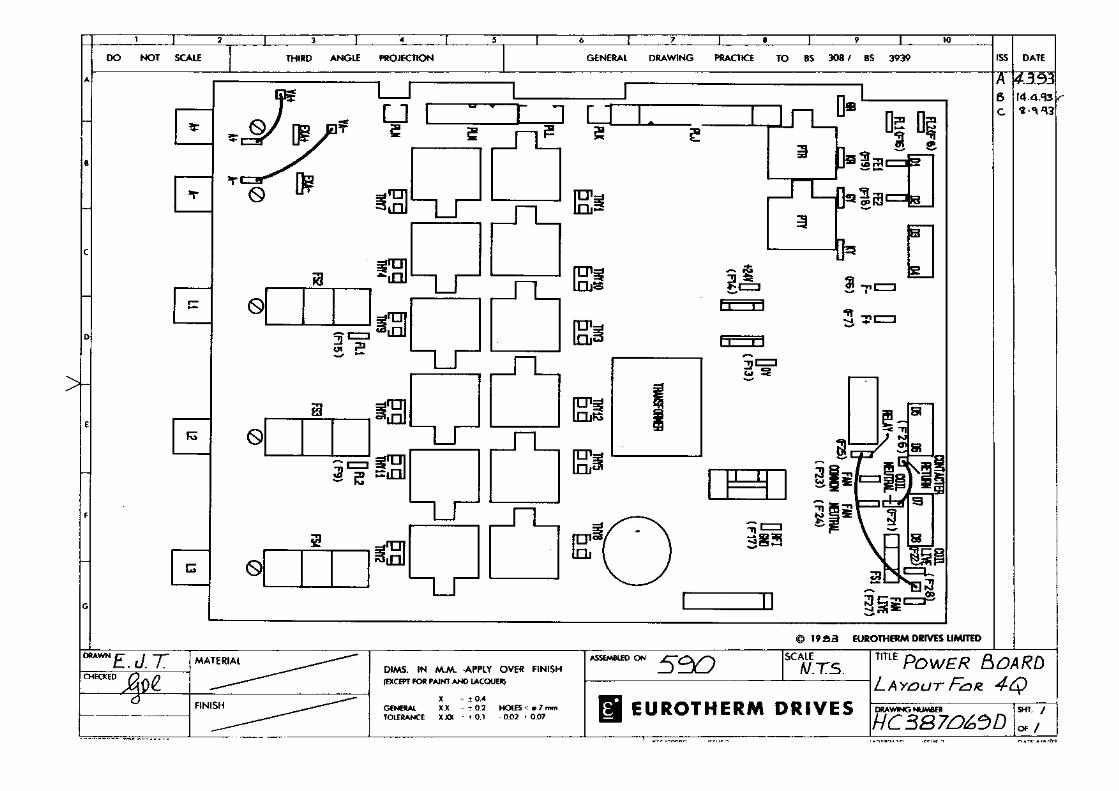

9 - 6
590 POWER BOARD (AH385621)
Replaces AH055050 From August 1995.Power supply specification as AH385851 described above.
Product Type590/7200 (4Q 720amp)591/7200 (2Q 720amp)
Subject of enhancementPower Board now updated to AH385621U001 (Sep 1995)This item has been updated to include improvements including:Surface Mount TechnologyRevised SMPS (as 590/592)Removal of Coding Module
CompatibilityThis part does not allow upgrading of existing Power Board (AH055050/385128). Repair/Service of existingproduct will continue to use identical parts as originally fitted.
Additions to Technical ManualSubject-External Supply Terminals D1 & D2These terminals are used for the External AC Supply connection (for the Motor Field Supply) when the InternalAC Supply is unused. The following actions must be taken:
1) These terminals are now energised when “Internal Field Supply” option is used, and the 3 phase supply(L1/2/3) is energised. Protection is available via the on-board Field supply fuses FS2, FS3.
2) When utilising the “External AC Supply” connection, internal wiring links must be removed and connected tostaging posts provided.The internal wiring links (Red and Yellow) are identified by the following procedurea) Isolate the Driveb) Loosen control board fixing screws (2 off) and orientate control board to allow access to power board.c) Identify internal field supply link (colour-Red) where it is connected by “Faston” at the left hand side ofTerminal D1. Remove this link from the faston connection and place on staging post “F8” located to the left. (Toenable positive identification of the correct link, Faston F8 should now be connected to FS2, and L1. Verify bycontinuity test)d) Identify internal field supply link (colour-Yellow) where it is connected by “Faston” at the mid-point belowterminals D1 & D2. Remove this link from the faston connection and place on staging post “F16” located to theleft. (To enable positive identification of the correct link, Faston F16 should now be connected to FS3, and L2.Verify by continuity test)e) The External Field Supply can now be connected via externally mounted fast acting 20 Amp fuses. (Note thatthe phase of D1 must be derived from L1, and the phase of D2 must be derived from L2).
POWER BOARD AH385621
D1 D2 D3 D4
RedF8
F16
tag.
Yellow

10 - 1
10 The European Directives and the 'CE' MarkCEMEPUntil recently each European drives manufacturer and importer has been interpreting the EMC directive and ‘CE’marking requirements differently. This has led to considerable confusion and frustration in the market place. Toprovide a unified approach, the European machines and drives manufactures, via their national trade associationshave formed the ‘European Committee of Manufacturers of Electrical Machines and Power Electronics’, termedCEMEP. This committee has produced a document entitled “Recommendations for Application of Power DriveSystems (PDS), European Council Directives - CE Marking and Technical Standardisation”, which will be followedby all major European Drives manufacturer. A copy is available from your local trade association or from your localEurotherm Drives office.
EMC DIRECTIVE'CE' EMC Responsibility
The subject of CE marking and EMC is explored in more detail in a separate Eurotherm Application manual entitled‘EMC Installation Guidelines for modules and systems’, part number HA388879, available from your localEurotherm Drives office. The following sections are the minimum necessary for basic understanding.
Eurotherm Drives are adhering to the CEMEP recommendations on ‘CE’ marking for EMC. According to SI No.2372, implementing the EMC directive into UK law, the requirement to CE mark for EMC, applies only to relevantapparatus that has ‘intrinsic function’ to the end user and which is placed on the market (supplied). The majorityof drive modules/systems sold by Eurotherm Drives will be incorporated into a higher system/apparatus or machinewhich includes (at least) the motor, cable and a driven load before providing intrinsic function to the end user. Assuch the majority of Eurotherm Drives products are categorised as components (CEMEP validity field 2) and itwould be incorrect for Eurotherm Drives to apply the CE mark or produce an EC Declaration of Conformity inrespect of EMC. It is the manufacturer/supplier/installer of the relevant apparatus (with the intrinsic function to theend user) who must demonstrate conformance to the EMC directive
However, in a minority of cases, single drives may have intrinsic function to the end user. An example is that of‘add on’ intrinsic function, where an existing fixed speed motor application (such as a fan or a pump) is converted tovariable speed with an add on drive module (CEMEP validity field 1). In this application Eurotherm Drives CEmark its drive module and issue an EC declaration of conformity. Because the validity of the ‘CE’ mark for EMC isnot known when the product is manufactured, the ‘CE’ mark will be applied via the product manual, and will not beon the product label. From 1997, when the ‘CE’ mark for the Low Voltage Directive becomes mandatory, the CEmark will appear on the product label, but its validity for EMC can only be identified from the product manual.
The validity of the ‘CE’ mark can be identified from the flowchart in figure 10.1, refer to SI No. 2372 forclarification of relevant apparatus.
To assist manufacturers/suppliers/installers of relevant apparatus, Eurotherms 590 drive modules are EMC compliantto EN50081-2 (1994) and prEN50082-2 (1992), when fitted with the specified filter and choke and installedaccording to these instructions, (as confirmed by the Manufacturers EMC declaration to be found at the end of thischapter).
Manufacturers/suppliers/installers of relevant apparatus (CEMEP validity fields 3 & 4) may use this compliance as abasis for their own justification of overall compliance with the EMC Directive.
It must be clearly understood by the customer before installation commences who is legally responsible forconformance with the EMC Directive. Misappropriation of the CE mark is a criminal offence.

10 - 2
Figure 10.1 Eurotherm EMC ‘CE’ Mark Validity Chart
THE E.D. EC DECLARATION OF CONFORMITY FOR EMC IS VALID FOR THE SPECIFIED ED MODULE
START
IS E.D. MODULE RELEVANT APPARATUS
WITH INTRINSIC FUNCTION TO END USER (CEMEP
VALIDITY FIELD 1)
NO
YES
FIT THE SPECIFIED E.D. EMC FILTER
WILL THE E.D. PRODUCT BE INSTALLED
ACCORDING TO THE INSTALLATIONGUIDELINES
NO
YES
E.D. = EUROTHERM DRIVES LIMITED
EMC 'CE' MARK CAN BE APPLIED TO E.D. MODULE TO GENERIC EMC STANDARDS:
EN50081-1(1992), EN50081-2(1994) ANDEN50082-1(1992) (AND prEN50082-2(1992)).
EMC INSTALLATION GUIDELINESSTATED IN MANUAL
EMC CHARACTERISTICS STATED IN MANUAL
OPTIONAL E.D. FILTERS AVAILABLE TO ASSIST USERSIN CONFORMANCE WITH THE
EMC DIRECTIVE
A GLOBAL EMC SOLUTIONMAYBE ADVANTAGEOUS
CEMEP VALIDITY FIELDS 2, 3 AND 4
THE E.D. MANUFACTURERS DECLARATIONFOR EMC IS VALID FOR THE SPECIFIEDMODULE WHEN INSTALLED CORRECTLY
NO EMC 'CE'MARK APPLIED TO E.D MODULE
MANUFACTURER/SUPPLIER/INSTALLERSRESPONSIBILITY TO CONFORM WITH EMC DIRECTIVE.E.D. EMC CHARACTERISTICS AND MANUFACTURERS
DECLARATION MAY BE USED AS A BASIS IN THE
RELEVANT APPARATUS
OVERALL PRODCT JUSTIFICATION

10 - 3
CONSIDERATION OF EMC ENVIRONMENT
When considering the relevant EMC emission and immunity standards it is important to distinguish between the following classes of EMC environments:
Residential, supplieddirectly from publicelectricity supply
Commercial andlight industry,supplied directlyfrom publicelectricity supply
Industrialinstallation with aseparatetransformer station
RF emission Immunity RF emission Immunity RF emission Immunity
Basic and GenericStandards
EN55011 (Class B) orEN50081-1(1992)
EN50082-1(1992) seebelow for referencedstandards
EN55011 (Class B) orEN50081-1(1992)
EN50082-1(1992) seebelow for referencedstandards
EN55011 (Class A) orEN50081-2(1994)
EN50082-2 (1992)see below for referencedstandards
New EMC ProductStandard (draft)for Power DriveSystems
IEC-22G/31/FDIS+
(will becomeEN 61800-3)
Unrestricted distribution(CEMEP-1):< 25 A Class B> 25 A Class A
Restricted distribution(CEMEP-2) Class A
see below EMC measures do nothave to be implemented
If interference in aneighbouringinstallation occurs, theoperator is responsiblefor taking measures toprevent interference. Inthis case the requiredemission levels must beadhered to at the pointof supply to the effectedneighbouringinstallation.
see below EMC measures do nothave to be implemented
If interference in aneighbouringinstallation occurs, theoperator is responsiblefor taking measures toprevent interference. Inthis case the requiredemission levels must beadhered to at the pointof supply to the effectedneighbouringinstallation.
see below
+ This new Product Standard Draft has not yet beenfinally passed and more important, is not EC approved.An EC Declaration of Conformity for EMC can only beissued with the approval of a "Competent Body". It isanticipated this standard will be officially releasedduring Q 3/4 1996.
* New standards to be introduced in the near future
Standards for immunity:IEC801-2 (IEC1000-4-2*): Electrostatic discharge (e.g. from electrostatically charged persons)
IEC801-3 (IEC1000-4-3/6*): Electromagnetic fields (e.g. from portable telephones)
IEC801-4 (IEC1000-4-4*): Fast electrical transients (burst) (e.g. from opening contacts in inductive circuits)
IEC801-5 (IEC1000-4-5): Voltage surges (e.g. on local lightning strikes).
Figure 10-2: EMC Emission and Immunity Standards applicable to 590 drive modules and similar equipment

10 - 4
When using the generic EMC standards, the 'Residential, commercial and light industry' emission limits (Class B) aremore stringent than the 'Industrial' (class A) limits, and so equipment which meets EN50081-1(1992) automaticallymeets EN50081-2(1994). Similarly, the 'Industrial' immunity requirements are more stringent than the 'Residential,commercial and light industry' requirements, and equipment which meets prEN50082-2(1992) automatically meetsEN50082-1(1992).
More and more Product Specific standards are being released with less onerous EMC requirements than the GenericStandards. When the new EMC Drive Product Standard for Power Drive System (EN61800-3) becomes available (Q3/4 1996), EMC filters will only be mandatory in ‘residential’ type EMC environments (if this is the mostappropriate standard to use for demonstrating conformance of the relevant apparatus). EMC competent bodies aretoday using the draft EMC Drive Product Standard to demonstrate conformance using the technical construction fileroute. The EMC Drive Product Standard as CEMEP is discussed in more detail in the Eurotherm Application manualentitled ‘EMC Installation Guidelines for modules and systems’, part number HA388879, available from your localEurotherm Drives office.
It is important for the customer to identify what EMC standards are to be applied to the final machine/system and inwhat EMC environment it will operate, so that any additional compliance costs can be minimised. It should beremembered that when two or more EMC compliant components are combined to form the final machine/system, theresulting machine/system may not be compliant. Emissions from combined components tend to be additive, whilstthe immunity remains constant.
FILTER SELECTION AND LINE CHOKE
590 drive modules can be 'CE' marked (as in CEMEP validity field 1) when used with the specified speciallydesigned EMC filters to comply with the mains terminal limits of EN55011 Class B (or EN50081-1) as indicatedpreviously, and when installed in accordance with the EMC installation instructions in this Product Manual(chapter 4). The Class A limit allows product to be used in ‘industrial ' EMC environments. Refer to Considerationof EMC environments, in this chapter for more details. The specified EMC filters for the 590 drive modules aresummarised in table A and B in Chapter 4 EMC Installation guidelines. The fitment of the specified EMC filter andline chokes is mandatory where 'CE' marking is applied.
If the customer is treating the 590 drive module as a component for supply to EMC competent professionalassemblers (CEMEP validity field 2)and is taking the EMC responsibility, then the filters are optional and mayassist the customer in achieving EMC compliance. In this situation the customer may also achieve compliance by lessexpensive more global measures depending on the limits to be achieved, such as the use of a combination of globalor local filtering and screening methods, natural mitigation through distance or use of distributed parasitic elementsof the existing installation.
FILTER INSTALLATION
The required EMC emission and immunity performance, and 'CE' marking of 590 drive modules can only beachieved when the EMC installation instructions in Chapter 4 are adhered to.
SPECIFICATION OF ACHIEVABLE EMC EMISSION AND IMMUNITY
590 drive modules with the option to be 'CE' marked meet the following EMC emission limits provided they areinstalled with the specified EMC filters and line chokes for 'CE' marking in accordance with the EMC installationinstructions.
Port Phenomenon Basic standard Level Generic standard
Enclosure Port radiated EN55011 (1991) Class B(cubicle mount)
EN50081-1 (1992)
Class A(wall mount)
EN50081-2 (1994)
AC Power Port conducted (withspecified filter)
EN55011 (1991) Class A EN50081-2 (1992)
AC Power Port conducted (no filterno filterno filterno filter) EN55011 (1991) 130dBµV @ 150kHz* (common mode)130dBµV @ 150kHz* (differential mode)Reducing with frequency by 20dB/decade
* 50 metres screened motor cable.
All 590 drive modules meet the following EMC immunity performance criteria as defined in prEN50082-2 (1992)when installed and used as recommended.

10 - 5
Port Phenomenon TestStandard
Level AcceptanceCriterion
GenericStandard
EnclosurePort
ESD
RF Field
IEC 1000-4*
IEC 1000-4
6 kV CD, 8 kV AD
10 V/m, 1 kHz AM
self recovery
no change
EN50082-1(1992)
PowerPorts
Fast Transient
Burst, Surge
IEC 1000-4,
IEC 1000-4
2 kV
1 kV (P-P), 2 kV (P-E)available late 1996
self recovery
self recovery
DraftprEN50082-2
(1992)
Signal &Control
Fast Transient Burst IEC 1000-4 2 kV self recovery
PowerInterfaces
Fast Transient Burst IEC 1000-4 2 kV self recovery
* only for cubicle mount.
The EMC filters for 590 drive modules may be flash tested in circuit up to DC 2850 V for 1 min Ensure all otherequipment that may be damaged by such flash testing has been suitably isolated/removed/short circuited asapplicable. Due to the internal capacitors between phase and earth, the DC voltage should be wound up slowly, toprevent excessive earth current. For similar reasons AC flash testing cannot be performed due to the excessive earthleakage current. Repeated flash testing is not recommended as it may degrade the insulation.
EMC RESPONSIBILITY OF MANUFACTURERS/SUPPLIERS/INSTALLERS
For end users of 590 drive modules, a correctly installed power drive system (PDS) created from the supplied 590will be compliant with the generic emission standards EN50081-2(1994) and for immunity prEN50082-2(1992) aspreviously indicated. Manufacturers/suppliers/installers of relevant apparatus may use this compliance as a basis fortheir own justification of overall compliance with the EMC Directive.
If it is the responsibility of the manufacturer/supplier/installer to establish EMC conformity and to 'CE' mark. Thereare three methods of demonstrating conformity:
1) Self certification to a relevant standard
2) Third party testing to a relevant standard
3) Writing a technical construction file stating the technical rationale as to why the relevant apparatus iscompliant. An EMC "competent body" must then assess this and issue a technical report or certificate todemonstrate compliance.
Upon demonstrating EMC compliance an EC-Declaration of Conformity for the apparatus or machine may be issuedand a 'CE' mark applied.
Professional end users with EMC expertise who are using drive modules and cubicle systems defined ascomponents who supply, place on the market or install the relevant apparatus must take responsibility fordemonstrating EMC conformance and applying the 'CE' mark and issuing an EC Declaration of Conformity.
Eurotherm GuideMore information is available in a separate Eurotherm Guide entitled “Short Form Overview of European Directivesfor Variable Speed Drives and Applications” part number HA389770 available from your local Eurotherm Drivesoffice.
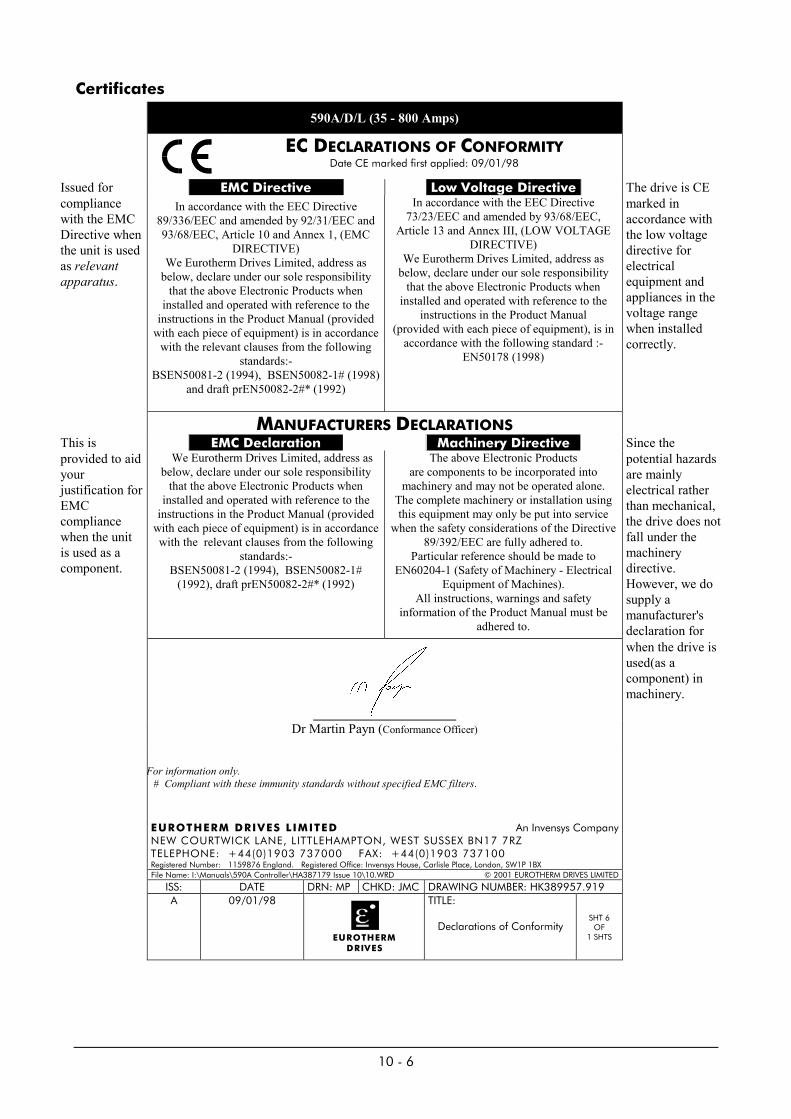
10 - 6
Certificates
590A/D/L (35 - 800 Amps)
EC DECLARATIONS OF CONFORMITYDate CE marked first applied: 09/01/98
Issued for EMC Directive Low Voltage Directive The drive is CEcompliancewith the EMCDirective whenthe unit is usedas relevantapparatus.
In accordance with the EEC Directive89/336/EEC and amended by 92/31/EEC and93/68/EEC, Article 10 and Annex 1, (EMC
DIRECTIVE)We Eurotherm Drives Limited, address as
below, declare under our sole responsibilitythat the above Electronic Products when
installed and operated with reference to theinstructions in the Product Manual (provided
with each piece of equipment) is in accordancewith the relevant clauses from the following
standards:-BSEN50081-2 (1994), BSEN50082-1# (1998)
and draft prEN50082-2#* (1992)
In accordance with the EEC Directive73/23/EEC and amended by 93/68/EEC,
Article 13 and Annex III, (LOW VOLTAGEDIRECTIVE)
We Eurotherm Drives Limited, address asbelow, declare under our sole responsibility
that the above Electronic Products wheninstalled and operated with reference to the
instructions in the Product Manual(provided with each piece of equipment), is in
accordance with the following standard :-EN50178 (1998)
marked inaccordance withthe low voltagedirective forelectricalequipment andappliances in thevoltage rangewhen installedcorrectly.
MANUFACTURERS DECLARATIONSThis is EMC Declaration Machinery Directive Since theprovided to aidyourjustification forEMCcompliancewhen the unitis used as acomponent.
We Eurotherm Drives Limited, address asbelow, declare under our sole responsibility
that the above Electronic Products wheninstalled and operated with reference to the
instructions in the Product Manual (providedwith each piece of equipment) is in accordancewith the relevant clauses from the following
standards:-BSEN50081-2 (1994), BSEN50082-1#
(1992), draft prEN50082-2#* (1992)
The above Electronic Productsare components to be incorporated into
machinery and may not be operated alone.The complete machinery or installation usingthis equipment may only be put into service
when the safety considerations of the Directive89/392/EEC are fully adhered to.
Particular reference should be made toEN60204-1 (Safety of Machinery - Electrical
Equipment of Machines).All instructions, warnings and safety
information of the Product Manual must beadhered to.
potential hazardsare mainlyelectrical ratherthan mechanical,the drive does notfall under themachinerydirective.However, we dosupply amanufacturer'sdeclaration forwhen the drive isused(as acomponent) inmachinery.
Dr Martin Payn (Conformance Officer)
For information only. # Compliant with these immunity standards without specified EMC filters.
EUROTHERM DRIVES LIMITED An Invensys CompanyNEW COURTWICK LANE, LITTLEHAMPTON, WEST SUSSEX BN17 7RZTELEPHONE: +44(0)1903 737000 FAX: +44(0)1903 737100Registered Number: 1159876 England. Registered Office: Invensys House, Carlisle Place, London, SW1P 1BXFile Name: I:\Manuals\590A Controller\HA387179 Issue 10\10.WRD © 2001 EUROTHERM DRIVES LIMITED
ISS: DATE DRN: MP CHKD: JMC DRAWING NUMBER: HK389957.919A 09/01/98
EUROTHERMDRIVES
TITLE:
Declarations of ConformitySHT 6
OF1 SHTS

11- 1
11. SPARES KITS AND SPARE PART IDENTIFICATION LIST
All spares requirements for the 590A/591A product family can be specified using an alpha-numeric code.For installations of 5 or more drives we recommend the holding of a complete spare drive.For installations of up to 5 drives we recommend the holding of a Spares Kit which can be orderedusing the Product Code and therefore saves time, obtains the best price and reduces the risk of poor sparescoverage.Note: rationalisation of drive rating can dramatically reduce the spares holdings.
Block No No of Digits Function1 7 Spares Order2 4 Product (590A/591A)3 10 Item (Kit or Part)4 4 Current Rating5 1 Supply Voltage (Power)6 1 Supply Voltage (Auxiliary)7 2 Special Options
The 7 blocks are defined as follows:
Block 1: SPARE4 (Identifies Spares Order)
Block 2: 590A (3 phase, 4 Quadrant regenerative convertor 35A to 720A.)591A (3 phase, 2 Quadrant non-regenerative convertor 35A to 720A.)4 Digits identifying spares for specific product i.e. 590A or 591A.
Block 3: 10 Digits identifying the specific Part (see list of available spares below)
Block 4: 4 Digits identifying the DC output current rating (see section 3)
Block 5: 1 Digit identifying the nominal 3 Phase AC power supply voltage (see section 3)
Block 6: 1 Digit identifying the auxiliary AC control supply (see section 3)
Block 7: 2 Digits identifying special options 0 No special options 01 to 98 Documented special options
ITEM ITEM CODE REFERENCEKIT KITCONTROL BOARD CONTROL_DRPOWER BOARD (ALL IN ONE) POWER_ALLPOWER BOARD (DISCRETE) POWERTRIGGER BOARD TRIGGERSUPPRESSION BOARD SUPPARMATURE THYRISTOR THYRISTORFIELD REGULATOR FIELD_REGFIELD THYRISTOR FIELD_THYFIELD DIODE FIELD_DIODAUXILIARY FUSE FUSE_AUXCODING FUSE FUSE_CODESTACK TEMPERATURE SWITCH TEMP_SWSTACK FAN INTERNAL FAN_INTSTACK FAN EXTERNAL FAN_EXTFAN CAPACITOR FAN_CAP
EXAMPLE: SPARE4/590A/KIT/0350/6/0/00(Spares Kit Complete: 590A, 35AMP, 415 Volt 3 Phase, 110 Volt Auxiliary, No Special Options)EXAMPLE: SPARE4/591A/CONTROL_DR/7200/6/0/00(Control Board in enclosure,591A,720AMP, 415 Volt 3 Phase,110 Volt Auxiliary, No Special Options)

11- 2
TABLE 1 - PRODUCT RATING 590A
PRODUCTRATING 590A
35.0AMP
70.0AMP
110.0AMP
150.0AMP
180.0AMP
270.0AMP
360.0AMP
450.0AMP
720.0AMP
XXXX.XAMP �
SPARES KITPART No. �
SPARE_4/590A/0350/KIT/�/�/0
SPARE_4/590A/0700/KIT/�/�/0
SPARE_4/590A/1100/KIT/�/�/0
SPARE_4/590A/1500/KIT/�/�/0
SPARE_4/590A/1800/KIT/�/�/0
SPARE_4/590A/2700/KIT/�/�/0
SPARE_4/590A/3600/KIT/�/�/0
SPARE_4/590A/4500KIT/�/�/0
SPARE_4/590A/7200/KIT/�/�/0
SPARE_5/598A/*****/KIT/�/�
CONTROLBOARD
CONTROL_DR CONTROL_DR CONTROL_DR CONTROL_DR CONTROL_DR CONTROL_DR CONTROL_DR CONTROL_DR CONTROL_DR CONTROL_DR
POWERBOARD
POWER_ALL POWER_ALL POWER_ALL POWER_ALL POWER_ALL POWER_ALL POWER POWER POWER POWER
TRIGGERBOARD
- - - - - - TRIGGER TRIGGER TRIGGER TRIGGER
SUPPRESSIONBOARD
- - - - - - SUPP SUPP SUPP SUPP
ARMATURETHYRISTOR
THYRISTOR THYRISTOR THYRISTOR THYRISTOR THYRISTOR THYRISTOR THYRISTOR THYRISTOR THYRISTOR CONTACTE.D. Ltd.
FIELDREGULATOR
FIELD_REG FIELD_REG FIELD_REG FIELD_REG FIELD_REG FIELD_REG FIELD_REG FIELD_REG FIELD_REG -
FIELDTHYRISTOR
- - - - - - - - - FIELD_THY
FIELDDIODE
- - - - - - - - - FIELD_DIOD
AUXILARYFUSE
FUSE_AUX FUSE_AUX FUSE_AUX FUSE_AUX FUSE_AUX FUSE_AUX FUSE_AUX FUSE_AUX FUSE_AUX FUSE_AUX
CODINGFUSE
FUSE_CODE FUSE_CODE FUSE_CODE FUSE_CODE FUSE_CODE FUSE_CODE FUSE_CODE FUSE_CODE FUSE_CODE CONTACTE.D. Ltd.
STACK TEMP.SWITCH
- - TEMP_SW TEMP_SW TEMP_SW TEMP_SW TEMP_SW TEMP_SW TEMP_SW CONTACTE.D. Ltd.
STACK FANINTERNAL
- - FAN_INT FAN_INT FAN_INT FAN_INT FAN_INT - FAN_INT CONTACTE.D. Ltd.
STACK FANEXTERNAL
- - - - - - - FAN_EXT FAN_EXT CONTACTE.D. Ltd.
FANCAPACITOR
- - - - FAN_CAP - FAN_CAP - - CONTACTE.D. Ltd.
� Spares Kit includes all listed items� Spares Kit is complete Control Chassis� Supply Voltage (Power) Refer to Section 3� Supply Voltage (Aux) Refer to Section 3

11- 3
TABLE 2 - PRODUCT RATING 591A
PRODUCTRATING 591A
35.0AMP
70.0AMP
110.0AMP
150.0AMP
180.0AMP
270.0AMP
360.0AMP
450.0AMP
720.0AMP
XXXX.XAMP �
SPARES KITPART No. �
SPARE_4/591A/0350/KIT/�/�/0
SPARE_4/591A/0700/KIT/�/�/0
SPARE_4/591A/1100/KIT/�/�/0
SPARE_4/591A/1500/KIT/�/�/0
SPARE_4/591A/1800/KIT/�/�/0
SPARE_4/591A/2700/KIT/�/�/0
SPARE_4/591A/3600/KIT/�/�/0
SPARE_4/591A/4500KIT/�/�/0
SPARE_4/591A/7200/KIT/�/�/0
SPARE_5/599A/*****/KIT/�/�
CONTROLBOARD
CONTROL_DR CONTROL_DR CONTROL_DR CONTROL_DR CONTROL_DR CONTROL_DR CONTROL_DR CONTROL_DR CONTROL_DR CONTROL_DR
POWERBOARD
POWER_ALL POWER_ALL POWER_ALL POWER_ALL POWER_ALL POWER_ALL POWER POWER POWER POWER
TRIGGERBOARD
- - - - - - TRIGGER TRIGGER TRIGGER TRIGGER
SUPPRESSIONBOARD
- - - - - - SUPP SUPP SUPP SUPP
ARMATURETHYRISTOR
THYRISTOR THYRISTOR THYRISTOR THYRISTOR THYRISTOR THYRISTOR THYRISTOR THYRISTOR THYRISTOR CONTACTE.D. Ltd.
FIELDREGULATOR
FIELD_REG FIELD_REG FIELD_REG FIELD_REG FIELD_REG FIELD_REG FIELD_REG FIELD_REG FIELD_REG -
FIELDTHYRISTOR
- - - - - - - - - FIELD_THY
FIELDDIODE
- - - - - - - - - FIELD_DIOD
AUXILARYFUSE
FUSE_AUX FUSE_AUX FUSE_AUX FUSE_AUX FUSE_AUX FUSE_AUX FUSE_AUX FUSE_AUX FUSE_AUX FUSE_AUX
CODINGFUSE
FUSE_CODE FUSE_CODE FUSE_CODE FUSE_CODE FUSE_CODE FUSE_CODE FUSE_CODE FUSE_CODE FUSE_CODE CONTACTE.D. Ltd.
STACK TEMP.SWITCH
- - TEMP_SW TEMP_SW TEMP_SW TEMP_SW TEMP_SW TEMP_SW TEMP_SW CONTACTE.D. Ltd.
STACK FANINTERNAL
- - FAN_INT FAN_INT FAN_INT FAN_INT FAN_INT - FAN_INT CONTACTE.D. Ltd.
STACK FANEXTERNAL
- - - - - - - FAN_EXT FAN_EXT CONTACTE.D. Ltd.
FANCAPACITOR
- - - - FAN_CAP - FAN_CAP - - CONTACTE.D. Ltd.
� Spares Kit includes all listed items� Spares Kit is complete Control Chassis� Supply Voltage (Power) Refer to Section 3� Supply Voltage (Aux) Refer to Section 3

12 - 1
12. SERVICE INFORMATION
12.1 MAINTENANCESolid state control equipment is very reliable and will give many years of trouble free operation.
However, it is good practice for the user to exercise a regular maintenance program for this equipment. Below isa typical sequence, but this may need to be modified by the actual conditions.
BEFORE PERFORMING ANY MAINTENANCE ON THIS PRODUCT ENSURE THAT ALL CIRCUITS ARE ISOLATED AND LOCKED OFF.
At six monthly intervals check:mounting fixtures }power connections } do not use asignal connections } compressed airthat for force vent units, the fan is able to rotate without obstruction. } gun for cleaningthat the ventilation spaces above and below are free from any obstruction. }that all covers are firmly installed. }
Note: 720Amp controllers and have removable rear access covers to all cleaning of air- path(see HG 049669)
Maintenance is always enhanced by the availability of spares sufficient to minimise down time.
Never forget that maintenance is more effective if your engineers have been properly trained. Eurotherm Drivesoperate a training program especially tailored for your requirement.
12.2 CUSTOMER ASSISTANCE FACILITIESEurotherm Drives operate a range of customer assistance facilities:• Sales• Service/Commissioning• Repairs• Technical• Training• System Design & Build
PLEASE BEFORE MAKING CONTACT - WHAT IS THE PRODUCT?WHAT IS THE MODEL NUMBER?WHAT IS THE SERIAL NUMBER?FAULT LOG REPORTCOMMISSIONING PARAMETERSMOTOR NAME-PLATE DETAILS
A LEGIBLE, CLEAR, AND CONCISE FAX IS THE BEST METHOD TO BEGIN THE ASSISTANCEYOUR REQUIRE.
Sales: Sales department will be able to quote price and delivery of replacement productand/or spares. Training and system design information is also available.
Service/Commissioning: Service department will be able to advise costs and availability of a Service Engineerto visit your installation to resolve your problem.
Technical: Technical advice can be given, prepare your enquiry properly to avoid confusion.
Repairs: Before returning equipment to the factory, ensure all details are checked
NOTE: IT IS IMPORTANT THAT THE RETURNED MATERIAL IS PROTECTED, TYPICALLY FROMINGRESS OR PACKAGING MATERIALS.E.G POLYSTYRENE/STYROFIL CHIPS WHICH MAY DAMAGE THE PRODUCT AND LEAD TOINCREASED REPAIR CHARGE AND REPAIR TIME.

12 - 2
Disposal
This product contains materials which are consignable waste under the Special Waste Regulations 1996 whichcomplies with the EC Hazardous Waste Directive – Directive 91/689/EEC.
We recommend you dispose of the appropriate materials in accordance with the valid environmental controllaws. The following table shows which materials can be recycled and which have to be disposed of in a specialway.
Material Recycle Disposal
Metal Yes No
Plastics material Yes No
Printed circuit board No yes
The printed circuit board should be disposed of in one of two ways:
1. High temperature incineration (minimum temperature 1200oC) by an incinerator authorised under parts A orB of the Environmental Protection Act.
2. Disposal in an engineered land fill site that is licensed to take aluminium electrolytic capacitors. Do notdispose of in a land fill site set aside for domestic waste.
Packaging
During transport our products are protected by suitable packaging. This is entirely environmentally compatibleand should be taken for central disposal as secondary raw material.


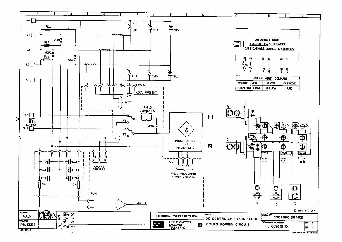


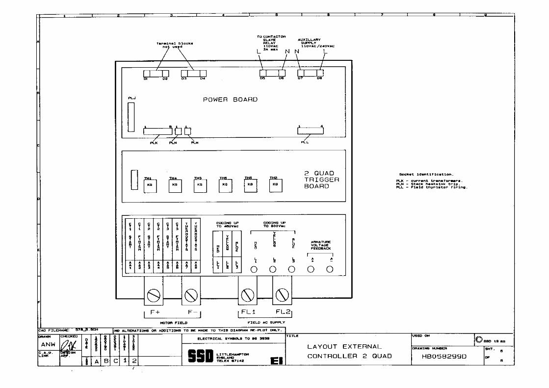
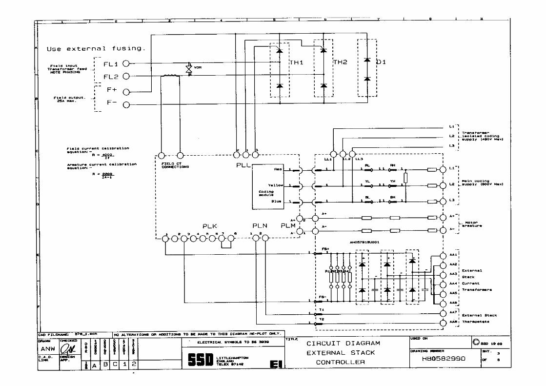


FIRST USED ON MODIFICATION RECORD
590A Product Manual
EUROTHERM DRIVES
DRAWING NUMBER
ZZ387179
SHT.2
OF 2
ISS. MODIFICATION C.P. No. DATE APPROVAL590A Product Manual HA387189Sheet 1 filed in drawing office.
8 Page 2-3 Added column 360A in table. 11219Page 2-4 Added “* Suitable ... supplies”.Section 10 LVD Requirements amendments. 11388Page 10-8 Added EC Declaration of Conformity forElectrical Safety. 11454 16.12.96 MP
9 Page 4-19 corrections to Table A. 11548Page 4-3 replaced HG386828 issue 6 with issue 7. 11748 21.04.97 CC
10 Warnings and Instructions page added ‘This is a product ...supply.’12-2 Added Disposal and Packaging information.Pages: Warnings and Instructions, 2-1, 2.2, 4.24 ReplacedprEN50178(1995) with EN50178(1998)
(13114)
10-6 Replaced Certificates with updated version. (13908)Page 2-1 Added ‘Output Controls’ and re-worded‘Adjustments’ paragraph.Page 2-2 replaced ‘Electrical Ratings’ with ‘Power’ and re-worded entire section.Chapter 2 - Replaced 45-65Hz with 50/60Hz.Page 4-2 replace ‘DO NOT PROTECTIVELYEARTH/GROUND THE MOTOR THROUGH THE 590DRIVE’ with ‘DO NOT ... ENCLOSURE’.Page 4-2 added ‘9. EMC ... contactor’4-19 added Total Filter Watt Loss columns.
12753 07.09.01 CC