euv light source development at euva - sematech light source development at euva. ... hiroto sato,...
TRANSCRIPT

EUV Source Workshop, 23 Feb 20031
EUV Light Source DevelopmentEUV Light Source Developmentat EUVAat EUVA
EUVA(Extreme Ultraviolet Lithography System Development Association)
Akira Endo, Hiroto Sato, Hiroshi Komori, Tamotsu Abe, Hakaru Mizoguchi, Koichi Toyoda,
Yasuhiro Horiike
EUV Source WorkshopFebruary 23, 2003
Santa Clara, California
EUV Source Workshop, 23 Feb 20032
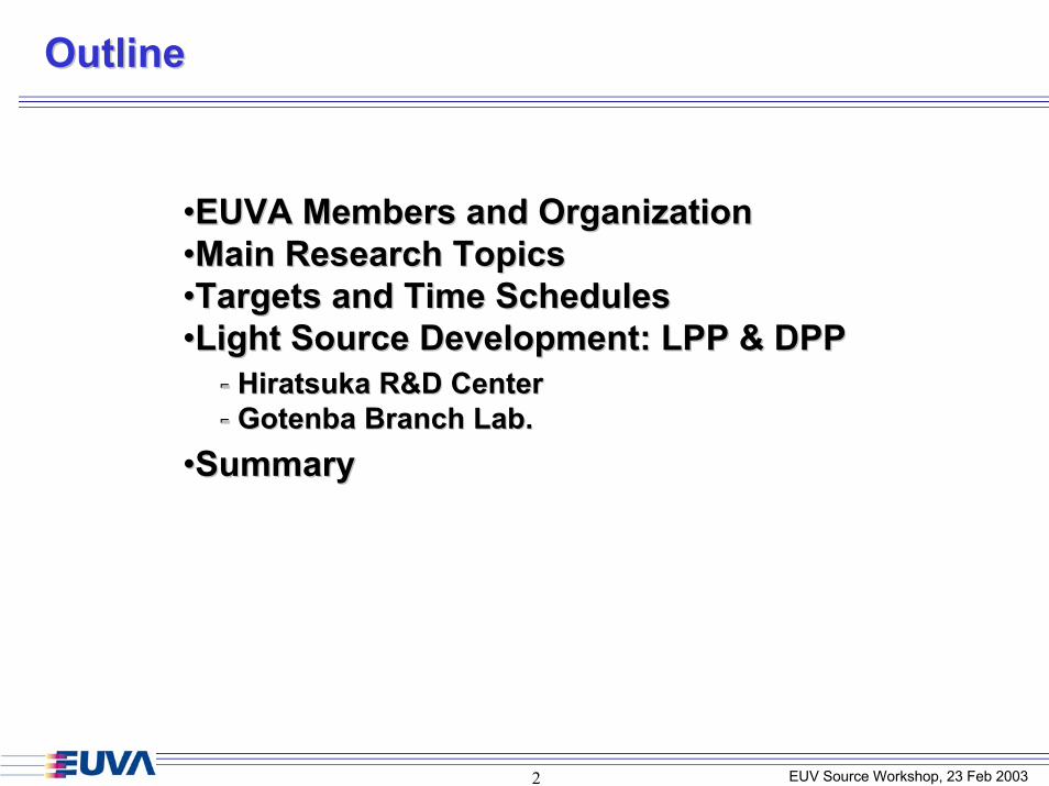
OutlineOutline
••EUVA Members and Organization EUVA Members and Organization ••Main Research TopicsMain Research Topics••Targets and Time SchedulesTargets and Time Schedules••Light Source Development: LPP & DPPLight Source Development: LPP & DPP
••Summary
--
Summary
- Hiratsuka R&D Center- Gotenba Branch Lab.
Hiratsuka R&D CenterGotenba Branch Lab.

EUV Source Workshop, 23 Feb 20033
EUVA OrganizationEUVA Organization
High Power LPP SystemKomatsu, USHIO,
Gigaphoton
Capillary discharge
Gotenba Branch Lab.High Power DPP System
USHIO, Gigaphoton
Nikon, CanonEvaluation
Universities
Tokyo Institute of Technology
Kumamoto UniversityCapillary discharge
Osaka UniversityPlasma Simulation
Himeji Institute of TechnologySolid Xe Target
Kyushu University LPP
Miyazaki UniversityLPP
HiratsukaResearch Center
Light Source Development ProjectLight Source Development Project
AISTSn Target
AIST: National Inst. of Adv. Industrial Sci. & Technology

EUV Source Workshop, 23 Feb 20034
EUVA Main TopicsEUVA Main Topics
Osaka UniversityOsaka University
Kyushu University Kyushu University
UniversitiesUniversities
Miyazaki UniversityMiyazaki UniversityHimeji Institute of TechnologyHimeji Institute of Technology
Tokyo Institute of TechnologyTokyo Institute of Technology
Kumamoto UniversityKumamoto University
High Power and High Quality EUV Light Source
Development
Topic 1Diagnostics of EUV Light Sources and
Mirror Damage
Topic 2

EUV Source Workshop, 23 Feb 20035
Targets and Time SchedulesTargets and Time Schedules
•High rep-rate power supply•Capillary discharge
20022002 20032003 20042004 20052005EUV Power@Intermediate focus
Development of DPP
Development of LPP
4W 10W
•Hiratsuka Research Center(Komatsu, Gigaphoton)
•AIST•Himeji Institute of Technology•Osaka University•Miyazaki University•Kyushu University
•Gotenba Branch Lab.(USHIO, Gigaphoton)
•Tokyo Institute of Technology•Kumamoto University
~2.5kW Nd:YAG ~5kW Nd:YAGXenon target
•Development of other targets•Simulation of plasma physics
Improved High repetition rateExperimental system
New targets
2006Fiscal YearFiscal Year

EUV Source Workshop, 23 Feb 20036
LPP DevelopmentLPP Development
Mar. 2003Mar. 2003Completion of 1st experimental setup.Completion of 1st experimental setup.
Evaluation of liquid jet target.Evaluation of liquid jet target.
Middle 2004Middle 2004Collector optics installed into chamber.Collector optics installed into chamber.Improved high power laser system.Improved high power laser system.
Mar. 2006Mar. 2006Higher EUV power and longer system lifetime.Higher EUV power and longer system lifetime.(Debris & thermal management).
1W(primary source)
(Debris & thermal management).
Milestone 14W @intermediate focus
Milestone 210W @intermediate focus
Collector optics
EUV source
Primarysource
Intermediatefocus Exposure system
LPPLPP

EUV Source Workshop, 23 Feb 20037
LPP System SchematicLPP System Schematic
Complete EUV SystemComplete EUV System
Xenon Xenon recirculation recirculation
systemsystem
EUV EUV chamberchamber
Laser Laser (MOPA)(MOPA)
Master Oscillator
Power Amplifier
Vacuum ChamberVacuum Chamber
TMPTMP
Collector Collector MirrorMirror
Nozzle Nozzle SystemSystem
PlasmaPlasma
LPPLPP

EUV Source Workshop, 23 Feb 20038
LPP SystemLPP System
ChamberChamber
Flying CircusFlying CircusⅡⅡ
NozzleNozzle SystemSystem
SpectrographSpectrographTMPTMP
LaserLaser
LPPLPP

EUV Source Workshop, 23 Feb 20039
Xenon Jet Experimental TestXenon Jet Experimental Test--StandStand
Nozzle SystemNozzle System
Xenon LiquefactionXenon LiquefactionSystemSystem
TestingTestingChamberChamber
XeXe Temperature: 160K Temperature: 160K -- 190K190KXeXe Pressure: Pressure: <5MPa<5MPa
50 mm50 mm
XeXe JetJet
Liquid Xenon Jet SystemLiquid Xenon Jet System
LPPLPP

EUV Source Workshop, 23 Feb 200310
Driver Laser System Driver Laser System -- SchematicSchematic --
AMP module--Average Power: 500 WattAverage Power: 500 Watt--Rep. Rate: Rep. Rate: 10 kHz10 kHz--Pulse duration: 30 nsPulse duration: 30 ns
Main-AMP1 Main-AMP2 Main-AMP3 Main-AMP4
LPPLPP
Pre-AMP4 Pre-AMP3 Pre-AMP2 Pre –AMP1
Master Oscillator Isolator

EUV Source Workshop, 23 Feb 200311
Driver Laser System Driver Laser System -- Beam ProfileBeam Profile --
After 3After 3--Main AmplifierMain Amplifier350W
Before Main AmplifierBefore Main Amplifier60W 350W60W
--We achieved 500 Watt @ 10kHz.We achieved 500 Watt @ 10kHz.--Further driver laser system improvements:Further driver laser system improvements:
Deformable mirror (beam quality)Deformable mirror (beam quality)Shorter pulse duration oscillator (several ns)Shorter pulse duration oscillator (several ns)
LPPLPP

EUV Source Workshop, 23 Feb 200312
Characteristics of EUV RadiationCharacteristics of EUV Radiation
EUV EnergyEUV Energy
0
2000
4000
6000
8000
10000
12000
14000
10 11 12 13 14 15Wavelength [nm]
Inte
nsity
[a.u
.]
EUV SpectraEUV Spectra
0
0.2
0.4
0.6
0.8
0 20 40 60 80 100 120
Laser energy [mJ]
In-b
and
EUV
ene
rgy
[mJ]
0
0.2
0.4
0.6
0.8
C.E
. [%
]
EUV energy
C.E.
--InIn--band EUV energy: 0.61 band EUV energy: 0.61 mJmJ--Conversion efficiency (C.E.): 0.53% (2%BW, 2Conversion efficiency (C.E.): 0.53% (2%BW, 2ππ srsr))
LPPLPP

EUV Source Workshop, 23 Feb 200313
DPP DevelopmentDPP Development
Mar. 2003Mar. 2003Construction of an experimental system.Construction of an experimental system.Primary source evaluation. Primary source evaluation.
Middle 2004Middle 2004Build collector optics into chamber.Build collector optics into chamber.Improved high repetition pulse power generator.Improved high repetition pulse power generator.
Mar. 2006Mar. 2006Higher power and longer lifetime.Higher power and longer lifetime.Debris mitigation,thermal management.
5W(primary source)
Debris mitigation,thermal management.
Milestone 14W @intermediate focus
Collector optics
EUV source
Primarysource
Intermediatefocus
Milestone 210W @intermediate focus
Exposure system
DPPDPP
EUV Source Workshop, 23 Feb 200314
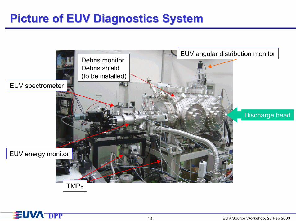
Picture of EUV Diagnostics SystemPicture of EUV Diagnostics System
EUV spectrometer
EUV energy monitor
TMPs
Debris monitorDebris shield(to be installed)
EUV angular distribution monitor
Discharge head
DPPDPP

EUV Source Workshop, 23 Feb 200315
Capillary ZCapillary Z--pinch Discharge Headpinch Discharge HeadEUV detectorsFlying Circus II (Scientec Engineering)
φ200 mm, r=500 mm, Mo/Si, multi-layer concave mirror+ Zr filter (Luxel Corp., 150-nm thick)+ AXUV-100G (IRD Inc.) photodiode
9-V biased, 50-Ohm terminatedEUV Spectrometer
9-17 nm1200 g/mm2-stage MCP + CCD
Diagnostics chamber
Downstream (~10-4 Torr)
Grounded anode
CapillaryMaterial : silicon carbide (SiC)Diameter : 2.3 mmLength : 6.0 mm
Filled gasXenonControlled by mass-flow controller
Insulator
High voltage cathode
Z-axis
5° 5°EUV monitor Spectrometer
Upstream (~1 Torr)Xenon gas flow
DPPDPP

EUV Source Workshop, 23 Feb 200316
Comparison of EUV spectra forComparison of EUV spectra forthe voltage scan and the gasthe voltage scan and the gas--pressure scanpressure scan
0
1 104
2 104
3 104
4 104
5 104
6 104
7 104
8 104
10 11 12 13 14 15 16 17
0.44 Torr (58 Pa)0.83 Torr (110 Pa)1.12 Torr (149 Pa)
Inte
nsity
(a.u
.)
Wavelength (nm)
0
5 104
1 105
1.5 105
2 105
2.5 105
3 105
10 11 12 13 14 15 16 17
2.5 kV3.5 kV4.5 kV5.4 kV
Inte
nsity
(a.u
.)
Wavelength (nm)
EUV spectra for 2.5 kV of charging voltage
EUV spectra for 1.12 Torr (149 Pa) of upstream gas pressure
7
8
9
10
11
12
13
14
15
0.2 0.4 0.6 0.8 1 1.2
2.5 kV3.5 kV4.5 kV5.4 kV
Rer
ativ
e in
-ban
d EU
V en
ergy
(%)
Upstream pressure (Torr)
Xe XIXe XII
Xe X
Xe IXSi VI
Relative spectral in-band EUV energy
[%]100)dI(
)dI(energyspectralbandinRerative nm 17.46
9.37nm
nm 13.77
13.23nm ×=−∫∫
λλ
λλ
- Higher gas pressure caused increase both in spectral intensity and relative in-band spectral intensity.- Higher current caused increase in spectral intensity. However, relative in-band spectral intensity decreased for 4.5 and 5.4 kV of charging voltage.- Higher current resulted in higher spectral intensity of Si VI lines. It means the higher debris generation for the given experimental parameters.
DPPDPP

EUV Source Workshop, 23 Feb 200317
Dependencies of EUV energy on gas pressure and Dependencies of EUV energy on gas pressure and conversion efficiency on stored energy for unit solid angleconversion efficiency on stored energy for unit solid angle
0
1
2
3
4
5
6
7
8
9
0.4 0.5 0.6 0.7 0.8 0.9 1 1.1 1.2Upstream pressure (Torr)
In-b
and
EUV
ener
gy (m
J/sr
)
2.5 kV3.5 kV4.5 kV5.4 kV
0.02
0.04
0.06
0.08
0.1
0.12
0.14
0.16
2 4 6 8 10 12 14 16 18
0.44 Torr (58.2 Pa)0.65 Torr (86.8 Pa)0.83 Torr (110 Pa)0.99 Torr (132 Pa)1.12 Torr (149 Pa)
Dis
sipa
ted
ener
gy-to
-EU
V co
nver
sion
effi
cien
cy (%
/sr)
Stored energy (J)
In-band EUV energy per pulseElectrical-to-EUV energy
conversion efficiency
- EUV energy increased in proportion as gas pressure increased, and was in proportion to stored energy of the generator.- 7.4 J of stored energy showed the highest conversion efficiency for the given current pulse and capillary load configuration at any gas pressure.
DPPDPP

EUV Source Workshop, 23 Feb 200318
Development Activities Development Activities Top 3 issues of technology developmentTop 3 issues of technology development
Issue 1 EUV conversion efficiencyIssue 1 EUV conversion efficiency:Optimization of the plasma(Pump pulsewidth, Size, density, Lower reabsorption)
Issue 2 Thermal managementIssue 2 Thermal management:Efficient cooling( Mirror & Chamber)
Issue 3 Background Gas absorptionIssue 3 Background Gas absorption:Efficient pumping, prevent diffusion
Topics for Precompetitive research/developmentTopics for Precompetitive research/developmentTopic 1Topic 1 Higher Repetition RateTopic 2Topic 2 Uniform EmissionTopic 3Topic 3 Stability Improvement

EUV Source Workshop, 23 Feb 200319
Update EUV Source Development Roadmap
EUV Source Performance RoadmapMetrics Mar-03 Sep-04 Mar-06
Demonstrated collectable EUV power in a2% spectral bandwidth in the regionbetween13-14nm (W)
LPP 1 WDPP 5 Wat primary
source
>4 >10
Available collection solid angle (sr) >πEtendue (mm2str) - <1 <1Demonstrated maximum repetition rate(kHz) 1 >5 >5Demonstrated steady state repetition rate(kHz) 1 >5 >5Dissipated total power in source region (atsteady state) (kW) 1 2.5 5Source-facing condenser lifetime (# ofpulses to 10% reflectance loss) - - >5x10⁸
Pulse to pulse intensity stability (3σ ) <10% <10%Pulse to pulse angular stability (3σ ) <10% <5%Key risk areas Efficiency/Thermal
EUV Source Workshop, 23 Feb 200320
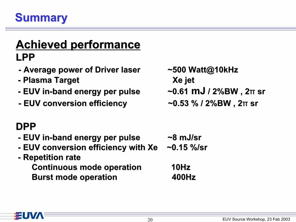
SummarySummary
Achieved performanceAchieved performanceLPPLPP-- Average power of Driver laser ~500 Watt@10kHzAverage power of Driver laser ~500 Watt@10kHz-- Plasma Target Plasma Target XeXe jetjet-- EUV inEUV in--band energy per pulse ~0.61band energy per pulse ~0.61 mJmJ / 2%BW , 2/ 2%BW , 2ππ srsr-- EUV conversion efficiency EUV conversion efficiency ~0.53 % / 2%BW , 2~0.53 % / 2%BW , 2ππ srsr
DPPDPP-- EUV inEUV in--band energy per pulse ~8band energy per pulse ~8 mJmJ//srsr-- EUV conversion efficiency with EUV conversion efficiency with Xe Xe ~0.15 %/~0.15 %/srsr-- Repetition rateRepetition rate
Continuous mode operation 10HzContinuous mode operation 10HzBurst mode operation 400HzBurst mode operation 400Hz

EUV Source Workshop, 23 Feb 200321
Acknowledgements
This work was performed under the management of
Extreme Ultraviolet Lithography System Development AssociationExtreme Ultraviolet Lithography System Development Association
,
a research and development program of
METIMETI.