ev3510 s0 r1 - joulwatt.com
TRANSCRIPT

EV3510_S0_R1 48VIN Micropower No-Opto
Isolated Flyback Converter with 75V/1.4A Switch Parameters Subject to ChangeParameters Subject to ChangeParameters Subject to ChangeParameters Subject to Change Without NoticeWithout NoticeWithout NoticeWithout Notice
JW3510_S0_R1 Rev.0.2 JoulWatt®Proprietary InformationPatent Protected. 1
Unauthorized Photocopy and Duplication Prohibited.
FEATURES
� 3.0V to 48VInput Voltage Range
� 1.4A, 75V Internal DMOS Power Switch
� Up to 430KHz Operating Frequency
� Low Quiescent Current
� Boundary Mode Operation at Heavy Load
� Burst Mode Operation at Light Load
� VOUT Set with a Single External Resistor
� Minimum Load <0.5% (Typ) of Full Output
� No Transformer Third Winding or Opto-Isolator
Required for Regulation
� Internal Compensation and Soft-Start
� Input under voltage lockout
� Output Short-Circuit Protection
� Thermal Protection
� SOT23-5 Package
APPLICATIONS
� Isolated Telecom, Automotive, Industrial, House
keeping Power Supplies
� Isolated Auxiliary Power Supplies
� Wide Input Voltage Range Micropower system
DESCRIPTION
JW®3510is a micropower isolated Flyback converter.By
sampling the isolated output voltage directly from the
primary-side flyback waveform, the part requires no third
winding or opto-isolator for regulation. The output voltage
can be programmed with a single external resistor.
Besides, internal compensation and soft-start further
reduce external component count.
The JW3510 operates with an input voltage range of 3.0V
to 48V and can deliver up to 7W of isolated output power.
The primary-side can deliver 1.4A peak current with an
internal integrated 75V N-Channel DMOS power switch.
The JW3510 is designed with boundary mode,
discontinuous mode and burst mode operation at different
load to improve load regulation and maintain high
efficiency while minimizing the output voltage ripple.
JW3510 is available in the SOT23-5 package. The high
level of integration results in a simple to use, low
component count, and high efficiency application solution
for isolated power delivery.
EVALUATION BOARD

EV3510_S0_R1 JoulWatt
JW3510_S0_R1 Rev.0.2 JoulWatt®Proprietary InformationPatent Protected. 2
Unauthorized Photocopy and Duplication Prohibited.
ELECTRICAL SPECIFICATIONS
Description Symbol Min Typ. Max Unit Comment
Input
Input voltage VIN 3 48 V
Output
Output voltage VOUT 4.75 5.25 V
Output current IOUT
0.32
A
VIN=5V
0.64 VIN=12V
0.84 VIN=24V
0.92 VIN=36V
Output Ripple Voltage VRIPPLE 100 mV Set oscilloscope at 20MHz bandwidth
Total Output Power
Continuous Output Power POUT 4.75 W
Efficiency η 80 %
Environmental
Ambient Temperature Ta -25 +45 ℃

EV3510_S0_R1 JoulWatt
JW3510_S0_R1 Rev.0.2 JoulWatt®Proprietary InformationPatent Protected. 3
Unauthorized Photocopy and Duplication Prohibited.
SCHEMATIC
BILL OF MATERIALS
Quantity Designator Comment Description Footprint Manufacturer Manufacturer
P/N
2 C1, C2 4.7uF/50V/1206 Capacitor 1206
3 C3, C4, C5 22uF/16V/1206 Capacitor 1206
1 D1 1N4148 Diode LL-34
1 D2 SBR15U50S Diode POWERDI5
1 R1 260K/5%/0805 Resistor 0805 Uniohm
0 R2 200K/5%/0805 Resistor 0805 Uniohm
1 R3 1K/5%/1206 Resistor 1206 Uniohm
1 R4 100K/1%/1206 Resistor 1206 Uniohm
1 T1 Lp=40uH,
Np:Ns=18:9 Transformer EE10
1 U1 JW3510 IC SOT23-5 Joulwatt JW3510
1 Z1 30V Zener LL-34

EV3510_S0_R1 JoulWatt
JW3510_S0_R1 Rev.0.2 JoulWatt®Proprietary InformationPatent Protected. 4
Unauthorized Photocopy and Duplication Prohibited.
PRINTED CIRCUIT BOARD LAYEROUT
Figure1————Top Silk Layer
Figure2————Top Layer
Figure3————Bottom Layer
QUICK START
1. Connect the load with VOUT, PGND.
2. Set the DC source to 3V~48V, turn off the source.
3. Connect the “+” of DC source to the “VIN”, and “-” to “GND”.
4. Turn on the DC source; the evaluation board starts operating in normal
condition.
5. To get more information, please refer to the datasheet of JW3510.

EV3510_S0_R1 JoulWatt
JW3510_S0_R1 Rev.0.2 JoulWatt®Proprietary InformationPatent Protected. 5
Unauthorized Photocopy and Duplication Prohibited.
TYPICAL PERFORMANCE CHARACTERISTICS
1. Efficiency
1.1Efficiency Curve
1.2Efficiency Data
Test condition: input voltage ranges 5V/12V/24V/36V, Output voltage Vo is 5V.
Input 10% load 25% load 50% load 75% load 100% load Average effi.
25%~100% load Test result
5V 75.58 82.46 81.24 79.02 74.55 79.32
OK 12V 80.89 84.56 84.23 82.87 81.10 83.19
24V 81.26 84.88 85.14 84.31 83.22 84.39
36V 79.70 84.13 84.83 83.99 83.46 84.10
2. Output Characteristics
2.1 Line and load regulation
Test condition: input voltage ranges 5V/12V/24V/36V, Output voltage Vo is 5V.
Input Voltage No load 1/4 load 1/2 load 3/4 load Full load Spec. Test result
5V 5.004 5.000 5.005 4.993 4.973 4.75V-5.25V OK
12V 4.984 4.985 4.994 5.001 4.991 4.75V-5.25V OK
24V 4.980 4.985 4.987 4.998 5.001 4.75V-5.25V OK
36V 4.977 4.979 4.979 4.991 4.997 4.75V-5.25V OK
Line regulation <1% < 2% OK
Load regulation <1% < 2% OK
Note: Output voltage was measured at the end PCB.
60
65
70
75
80
85
90
0 0.2 0.4 0.6 0.8 1 1.2
eff
.(%
)
Io(A)
Efficiency
5V 12V 24V 36V

EV3510_S0_R1 JoulWatt
JW3510_S0_R1 Rev.0.2 JoulWatt®Proprietary InformationPatent Protected. 6
Unauthorized Photocopy and Duplication Prohibited.
4.84
4.89
4.94
4.99
5.04
5.09
5.14
5.19
0 0.1 0.2 0.3 0.4 0.5 0.6 0.7 0.8 0.9 1
5V 12V 24V 36V
3. Dynamic Load Response
Test condition: input voltage ranges 5V/12V/24V/36V, Output voltage Vo is 5V.
Frefuency:100Hz; duty cycle: 50%; slew rate: 2.5A/μs; load: 0.48A->4.32A->0.48A.
Input Voltage Load Vomin~Vomax
5V 0.04A->0.4A->0.04A 4.75V~5.25V
12V 0.08A->0.8A->0.08A 4.75V~5.25V
24V 0.11A->1.1A->0.11A 4.75V~5.25V
36V 0.13A->1.3A->0.13A 4.75V~5.25V

EV3510_S0_R1 JoulWatt
JW3510_S0_R1 Rev.0.2 JoulWatt®Proprietary InformationPatent Protected. 7
Unauthorized Photocopy and Duplication Prohibited.
4. Operation Modes
Test condition: input voltage ranges 5V/12V/24V/36V, Output voltage Vo is 5V.
Burst Mode WaveformsDiscontinuous Mode Waveforms
Boundary Mode Waveforms
5. ShortCircuitProtection
Test condition: input voltage ranges 5V/12V/24V/36V. Output is short circuit condition.
Entry Recovery
CH1:VSWCH3:VO CH4:ISW
Condition: Vin=5V
CH1:VSWCH3:VO CH4:ISW
Condition: Vin=5V
Vin=5V

EV3510_S0_R1 JoulWatt
JW3510_S0_R1 Rev.0.2 JoulWatt®Proprietary InformationPatent Protected. 8
Unauthorized Photocopy and Duplication Prohibited.
CH1:VSWCH3:VO CH4:ISW
Condition: Vin=12V
CH1:VSWCH3:VO CH4:ISW
Condition: Vin=12V
Vin=12V
CH1:VSWCH3:VO CH4:ISW
Condition: Vin=24V
CH1:VSWCH3:VO CH4:ISW
Condition: Vin=24V
Vin=24V
CH1:VSWCH3:VO CH4:ISW
Condition: Vin=36V
CH1:VSWCH3:VO CH4:ISW
Condition: Vin=36V
Vin=36V
EV3510_S0_R1 JoulWatt
JW3510_S0_R1 Rev.0.2 JoulWatt®Proprietary InformationPatent Protected. 9
Unauthorized Photocopy and Duplication Prohibited.
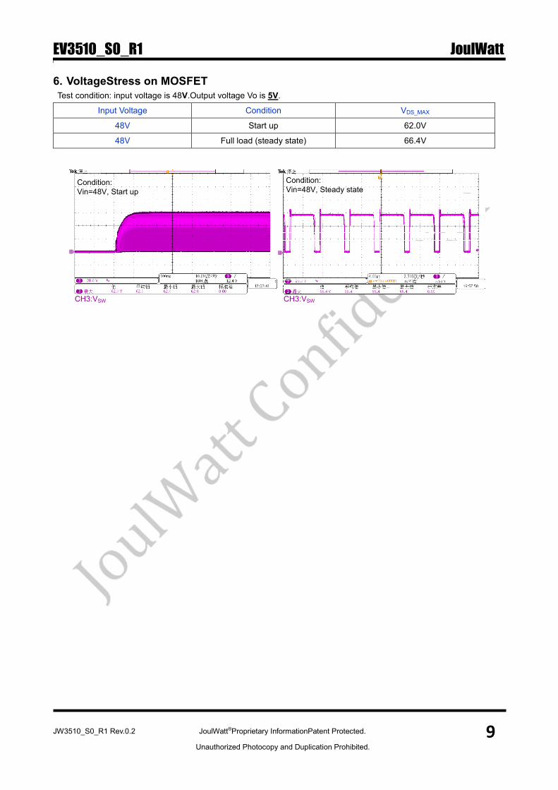
6. VoltageStress on MOSFET
Test condition: input voltage is 48V.Output voltage Vo is 5V.
Input Voltage Condition VDS_MAX
48V Start up 62.0V
48V Full load (steady state) 66.4V
CH3:VSW
Condition:
Vin=48V, Start up
CH3:VSW
Condition:
Vin=48V, Steady state

EV3510_S0_R1 JoulWatt
JW3510_S0_R1 Rev.0.2 JoulWatt®Proprietary InformationPatent Protected. 10
Unauthorized Photocopy and Duplication Prohibited.
IMPORTANT NOTICE
� Joulwatt Technology Inc. reserves the right to make modifications, enhancements, improvements,
corrections or other changes without further notice to this document and any product described herein. � Any unauthorized redistribution or copy of this document for any purpose is strictly forbidden.
� Joulwatt Technology Inc. does not warrant or accept any liability whatsoever in respect of any products
purchased through unauthorized sales channel.
Copyright © 2018 EV3510_S0_R1 Incorporated.
All rights are reserved by Joulwatt Technology Inc.