evaluating websocket and webrtc in the context of a mobile - kth
TRANSCRIPT

Degree project inCommunication Systems
Second level 300 HECStockholm Sweden
G U N A Y M E R T K A R A D O G A N
Evaluating WebSocket and WebRTC inthe Context of a Mobile Internet of
Things Gateway
K T H I n f o r m a t i o n a n d
C o m m u n i c a t i o n T e c h n o l o g y
Evaluating WebSocket and WebRTC in the Context of aMobile Internet of Things Gateway
Gunay Mert Karadogan
Master of Science Thesis
Embedded SystemsSchool of Information and Communication Technology
KTH Royal Institute of Technology
Stockholm Sweden
12 January 2013
Examiner Professor Gerald Q Maguire Jr
ccopy Gunay Mert Karadogan 12 January 2013
Abstract
This thesis project explores two well-known real-time web technologiesWebSocket and WebRTC It explores the use of a mobile phone as a gatewayto connect wireless devices with short range of radio links to the Internet in orderto foster an Internet of Things (IoT)
This thesis project aims to solve the problem of how to collect real-time datafrom an IoT device using the Earl toolkit With this thesis project an Earl device isable to send real-time data to Internet connected devices and to other Earl devicesvia a mobile phone acting as a gateway This thesis project facilitates the use ofEarl in design projects for IoT devices
IoT enables communication with many different kinds of ldquothingsrdquo such as carsfridges refrigerators light bulbs etc The benefits of IoT range from financialsavings due to saving energy to monitoring the heart activity of a patient withheart problems There are many approaches to connect devices in order to createan IoT One of these approaches is to use a mobile phone as a gateway ie to actas a router between IoT and the Internet
The WebSocket protocol provides efficient communication sessions betweenweb servers and clients by reducing communication overhead The WebRTCproject aims to provide standards for real-time communicationstechnology WebRTC is important because it is the first real-time communicationsstandard which is being built into browsers
This thesis evaluates the benefits which these two protocols offer when usinga mobile phone as a gateway between an IoT and Internet This thesis projectimplemented several test beds collected data concerning the scalability of theprotocols and the latency of traffic passing through the gateway and presentsa numerical analysis of the measurement results Moreover an LED modulewas built as a peripheral for an Earl device The conclusion of the thesis is thatWebSocket and WebRTC can be utilized to connect IoT devices to Internet
i
Sammanfattning
I detta examensarbete utforskas tva valkanda realtidsteknologier pa internetWebSocket och WebRTC Det utforskar anvandandet av en mobiltelefon somgateway for att ansluta tradlosa enheter - med kort rackvidd - till Internet for attskapa ett Internet of Things (IoT)
Det har examensarbetet forsoker med hjalp av verktyget Earl losa problemetmed hur insamlandet av realtidsdata fran en IoT-enhet skall genomforas I dethar examensprojektet kan en Earl-enhet skicka data i realtid till enheter medInternetanslutning samt till andra Earl-enheter med hjalp av en mobiltelefon somgateway Detta projektarbete forenklar anvandandet av Earl i design-projekt orIoT-enheter
IoT tillater kommunikation mellan olika sorters enheter sa som bilar kyl- ochfrysskap glodlampor etc Fordelarna med IoT kan vara allt fran ekonomiska -tack vare minskad energiforbrukning - till medicinska i form av overvakning avpuls hos patienter med hjartproblem Det finns manga olika tillvagagangssatt foratt sammankoppla enheter till ett IoT Ett av dessa ar att anvanda en mobiltelefonsom en gateway dvs en router mellan IoT och internet
WebSocket-protokollet erbjuder effektiv kommunikation mellan web-servraroch klienter tack vare minskad overflodig dataoverforing WebRTC-projektet villerbjuda standarder for realtidskommunikation WebRTC ar viktigt da det ar denforsta sadana standarden som inkluderas i weblasare
Det har examensarbetet utvarderar fordelarna dessa tva protokoll erbjuder idet fallet da en mobiltelefon anvands som gateway mellan ett IoT och InternetI det har examensprojektet implementerades ett flertal testmiljoer protokollensskalbarhet och fordrojningen av trafiken genom mobiltelefonen (gateway) undersoktesDetta presenteras i en numerisk analys av matresultaten Dessutom byggdes enLED-modul som tillbehor till en Earl-enhet Slutsatsen av examensarbetet ar attWebSocket och WebRTC kan anvandas till att ansluta IoT-enheter till Internet
iii
Acknowledgements
I would like to acknowledge my gratitude to my examiner Professor Gerald QMaguire Jr for his helpful comments and continuous suggestions during thedevelopment of this thesis
I thank my classmate Deniz Akkaya for letting me extend his thesis project bytaking a different approach
Last but not the least I would like to thank my family for supporting methroughout my life
v
Contents
1 Introduction 111 Problem Description 212 Problem Context 413 Goal 514 Thesis Structure 615 Methodology 6
2 WebSocket Experiments 721 Background 8
211 Scaling WebSocket Connections 1022 Related Work 1223 Goal 1324 Tools and Experimental Setup 14
241 Command Line Tools 142411 SSH 152412 Sar 152413 kSar 162414 Git 162415 NTP 172416 Gnuplot 17
242 NodeJS Server 17243 Amazon Web Services 23
2431 Problems with Virtualization 232432 Setting Up Servers 24
244 Load Balancer HAProxy 26245 Redis Layer 28
25 Data Collection 29251 Test Scripts 29
2511 loadjs 302512 appjs 31
252 Test Servers 31
vii
viii CONTENTS
253 Testing 3226 Data Analysis 34
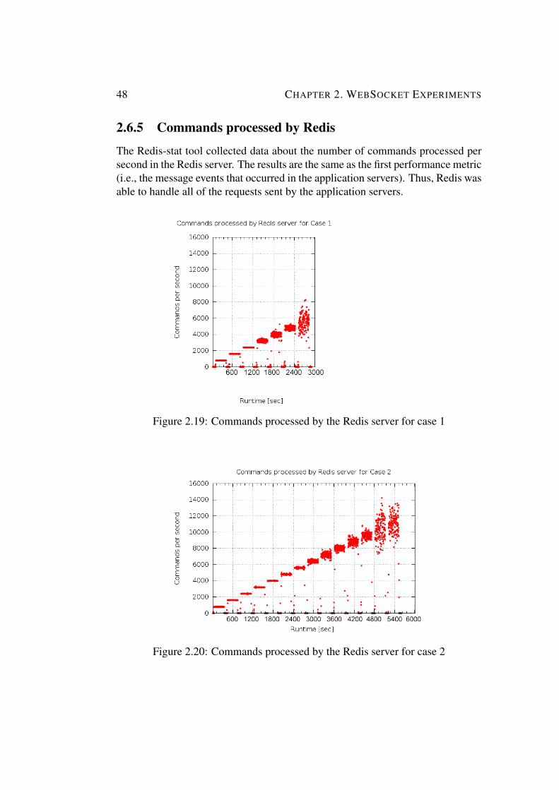
261 Throughput 34262 Message Service Time and Event Loop Lag 36263 Response Time 42264 CPU Usage 45265 Commands processed by Redis 48266 Events in Client Instances 49
27 Conclusion 50
3 WebRTC Experiments 5131 Background 51
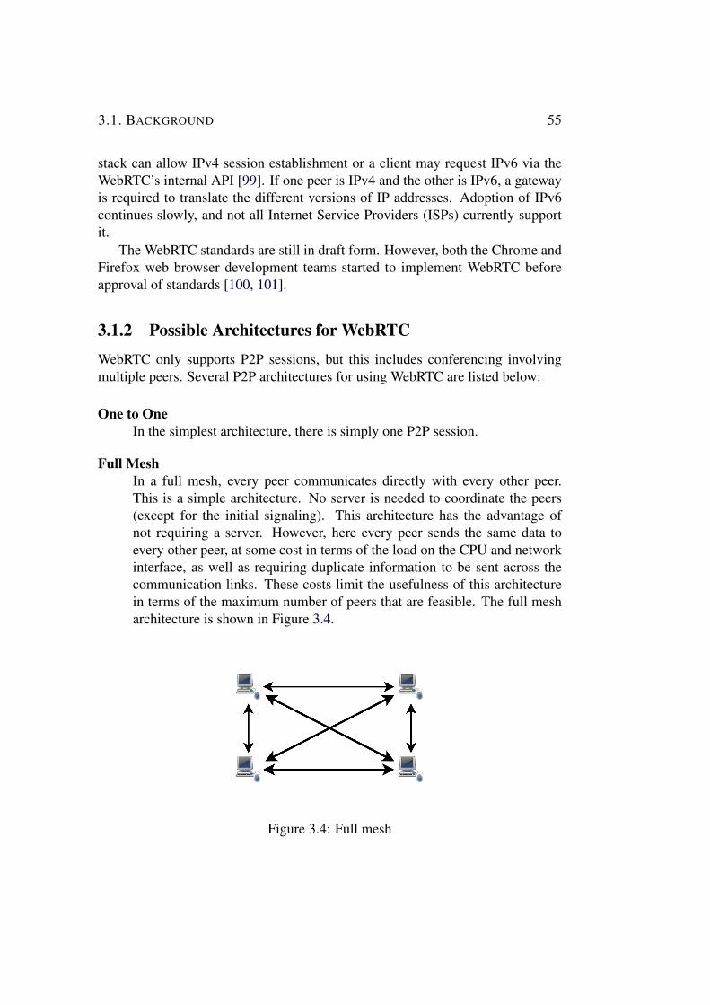
311 WebRTC Protocols 52312 Possible Architectures for WebRTC 55
32 Related Work 5733 Goal 5834 WebRTC API 59
341 RTCPeerConnection 59342 RTCSessionDescription 60343 RTCIceCandidate 61344 RTCDataChannel 62345 PeerJS 63
3451 PeerJS Client 633452 PeerServer 64
35 Experimental Setup 6536 Data Collection 6637 Data Analysis 68
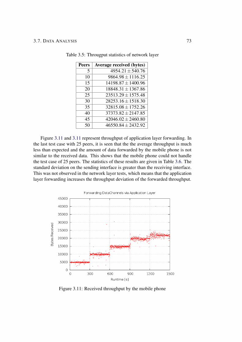
371 Forwarding DataChannels over a Mobile Phone 683711 One-way delay 683712 Throughput 71
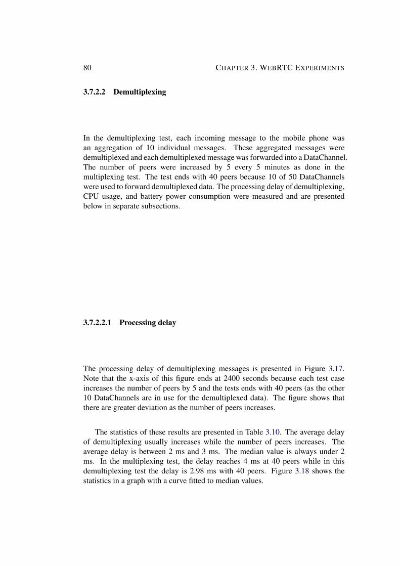
372 Multiplexing and Demultiplexing DataChannels 743721 Multiplexing 743722 Demultiplexing 80
38 Conclusion 85
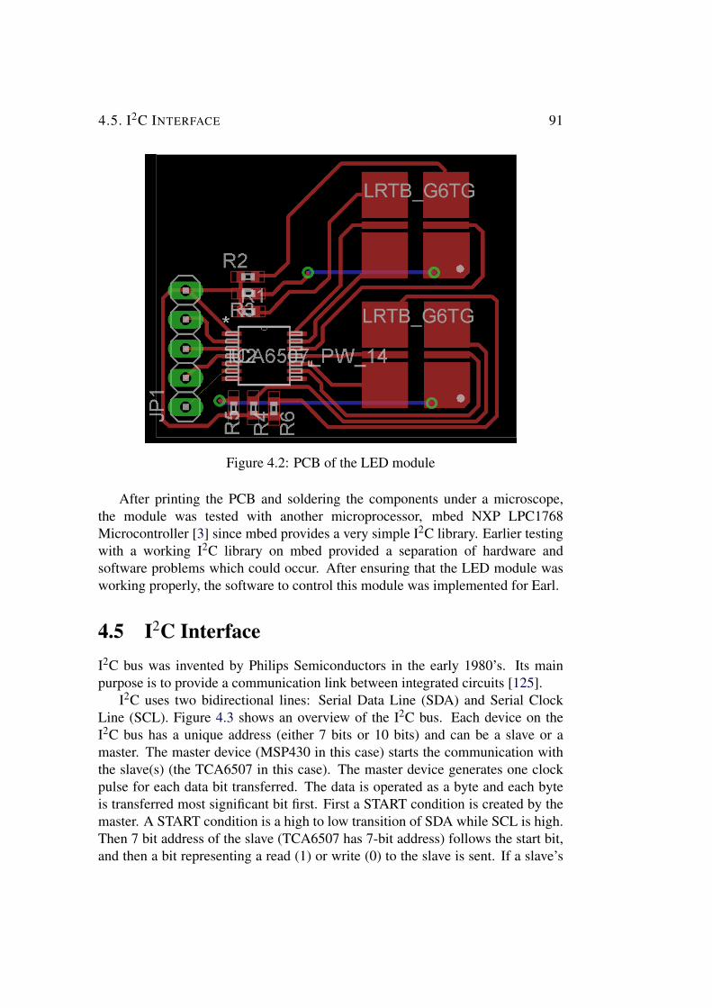
4 LED Module for Earl 8741 Background 8742 Goal 8843 Components 8844 Schematic 8945 I2C Interface 91
CONTENTS ix
46 Software 9347 Conclusion 95
5 Conclusion 9751 Conslusion 9752 Future Work 9853 Required Reflections 99
Bibliography 101
A Network Kernel Configuration 113
B HAProxy Configuration 115
C Example of WebRTC DataChannel API 117
D Googlersquos STUN Servers 119
List of Figures
11 LED module Earl Phone and Internet 5
21 Architecture for WebSocket Tests 722 Polling versus Long Polling 823 WebSocket Traffic 924 Proxy Types 1125 Publishers and Subscribers 1426 Message Events for Case 1 3527 Message Events for Case 2 3528 Message Service Time For Case 1 3729 Message Service Time For Case 2 37210 Event Loop Lag for Case 1 38211 Event Loop Lag for Case 2 38212 Response Time for Case 1 42213 Response Time for Case 2 43214 CPU Usage of the Application Server for Case 1 45215 CPU Usage of the Application Servers for Case 2 46216 CPU Usage of the Redis Server for Case 2 47217 CPU Usage of the HAProxy Server for Case 2 47218 CPU Usage of Opening and Terminating Connections for Case 1 47219 Commands Processed by the Redis Server for Case 1 48220 Commands Processed by the Redis Server for Case 2 48221 Number of message Events created by the Client Servers 49
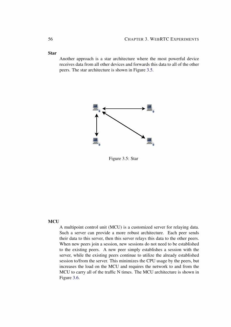
31 P2P WebRTC Architecture 5232 NAT 5333 TURN and STUN 5434 WebRTC - Full Mesh 5535 WebRTC - Star 5636 WebRTC - MCU 5737 SDP flow in WebRTC 6138 One-way delay of network layer 69
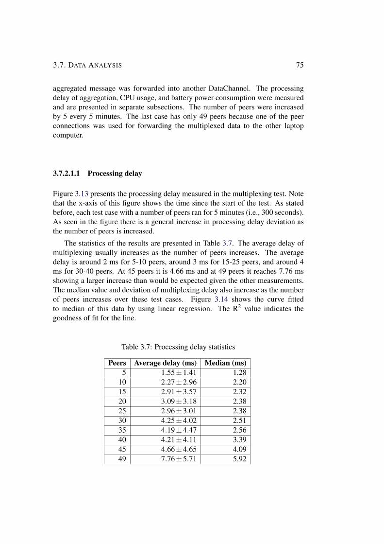
xi
xii LIST OF FIGURES
39 One-way delay of application layer 70310 Received throughput of network layer Sent throughput was the
same 72311 Received throughput by the mobile phone 73312 Sent throughput by the mobile phone 74313 Processing delay of multiplexing DataChannels 76314 Processing delay of multiplexing DataChannels 76315 CPU usage of multiplexing DataChannels 77316 Battery power consumption of multiplexing DataChannels 79317 Processing delay of demultiplexing DataChannels 81318 Processing delay of demultiplexing DataChannels 82319 CPU usage of demultiplexing DataChannels 83320 Battery power consumption of demultiplexing DataChannels 84
41 Schematic of the LED module 9042 PCB of the LED module 9143 General overview of I2C bus 9244 Data flow on I2C bus 92
List of Tables
21 Hardware specification of the local computer 1522 Parameters of the scripts 3123 Specification of the Instances 3224 Number of events per second for case 1 3625 Number of events per second for case 2 3626 Message service time statistics for case 1 3927 Message service time statistics for case 2 3928 Event loop lag statistics for case 1 4029 Event loop lag statistics for case 2 40210 Response time statistics for case 1 43211 Response time statistics for case 2 44
31 Comparison of WebSocket and RTCDataChannel 6232 Hardware Specification of WebRTC tests 6533 One-way delay statistics of network layer 7134 One-way delay statistics of application layer 7135 Througput statistics of network layer 7336 Througput statistics of application layer 7437 Processing delay statistics 7538 CPU load statistics of multiplexing 7839 Battery power consumption statistics of multiplexing 79310 Processing delay statistics 81311 CPU load statistics of demultiplexing 83312 Battery power consumption statistics of demultiplexing 84
41 Component list of the LED module 90
xiii
List of listings
21 Request to server 1022 Response from server 1041 Pseudo code of functions in i2cc 9342 Pseudo code of functions in tca6507c 94
xv
List of Acronyms and Abbreviations
6LoWPAN IPv6 over Low Power Wireless Area Network
AMI Amazon Machine Images
AWS Amazon Web Services
API Application Programming Interface
AJAX Asynchronous JavaScript and XML
BLE Bluetooth Low Energy
CPU Central Processing Unit
DTLS Datagram Transport Layer Protocol
DNS Domain Name System
EC2 Elastic Compute Cloud
HTTP Hypertext Transfer Protocol
HTTPS Hypertext Transfer Protocol Secure
I2C Inter-Integrated Circuit
IAAS Infrastructure as a Service
ICE Interactive Connectivity Establishment
IETF Internet Engineering Task Force
IoT Internet of Things
IP Internet Protocol
JSON JavaScript Object Notation
xvii
xviii LIST OF ACRONYMS AND ABBREVIATIONS
LED Light-emitting Diode
MCU Multipoint Control Unit
NAT Network Address Translation
PCB Printed Circuit Board
P2P Peer to Peer
RTC Real-Time Communication
RTP Real-time Transport Protocol
SIP Session Initiation Protocol
SMD Surface-Mount Device
SSH Secure Shell
SSL Secure Sockets Layer
STUN Session Traversal Utilities for NAT
SCTP Stream Control Transport Protocol
TCP Transmission Control Protocol
TURN Traversal Using Relays around NAT
UDP User Datagram Protocol
WebRTC Web Real-Time Communication
WSS WebSocket Secure
W3C World Wide Web Consortium
XMPP Extensible Messaging and Presence Protocol
Chapter 1
Introduction
The Internet of Things (IoT) is an evolving concept that enables interaction withobjects around us through sensors actuators mobile devices and so forth It isa broad vision that assumes that there will be sensors on many different kinds ofthings and that these sensors are connected to the Internet or to other computersystems This potentially large amount of sensor data may help us to understandthe world around us Additionally these things may have actuators - so that wecan act on the physical world This vision has been known by different namesover the past decades pervasive computing ubiquitous computing smart objectsand now IoT
According to Ciscorsquos Internet Business Solutions Group in 2010 the numberof devices connected to the Internet was 125 billion while the worldrsquos humanpopulation was 68 billion thus the average number of connected devices perperson was 184 [1] Looking to the future it is predicted that by 2015 there willbe 25 billion devices connected to the Internet and by 2020 this number will be50 billion [1] This expected growth is due to both smartphones and IoT
IoT can be seen as a set of systems that collect data process this dataand then allow us to react to this data (in many cases potentially by acting onsomething in the real-world) IoT utilizes many computer and communicationtechnologies Having such large numbers of devices introduces a numberof new requirements such as analyzing big data new server architectureslarger networking address spaces (such as provided by IPv6) and new mobileexperiences These technologies frequently utilize real-time web protocols datamanagement in-memorycomputing and hardware toolkits This thesis project was driven by theintroduction in another thesis project (described in the next section) of a newhardware toolkit This thesis project will focus on real-time web protocols
1
2 CHAPTER 1 INTRODUCTION
11 Problem DescriptionWith the evolving technology many toolkits have been introduced into the marketsuch as Arduino [2] mBed [3] and littleBits [4] Interaction designers at theICT Sweden Mobile Life research institute [5] wanted to have their own toolkitMobile Life is a research institute with a focus on mobile services involvingresearchers from computer science and interaction design In this institute amasterrsquos student Deniz Akkaya implemented a toolkit called Earl [6] Earl isa library of sensors and actuators that can be connected to the Internet througha mobile phone or a tablet An Earl instance is implemented with a low powerwireless network interface such as ANT+ [7] or Bluetooth low energy (BLE)[8] and a low power microcontroller such as Texas Instrumentsrsquo MSP430 [9]Such a device sends sensor data to a mobile phone via a wireless communicationlink - typically BLE This data is forwarded to one or more web services by amobile phone Earl aims to provide the user with a means to connect differenttypes of sensors or actuators and to see how these different sensors impact usersrsquointeractions Earl enables designers to create proof of concept systems faster thanimplementing a system from scratch
The Mobile Life research institute was asked to conduct a project for ABBSweden[10] in order to prevent boredom of workers working with ABBrsquos controlsystems in factories Ethnographic studies were carried out to understand thereason for this boredom in control rooms However these studies did not helpto decide on a feasible product to help the control room workers avoid boredomMoreover a step-by-step design process would not work because there was notenough time or a predefined problem where a product was specified Thereforeit was decided to use a co-designing method using technology probes [11]Technology probes are simple and flexible devices used in a design process aimingto understand the needs and desires of users Technology probes involve the usersactively in the design process and inspire users and designers to formulate newproduct ideas In the case of this project for ABB Sweden the main aim was tolet the workers find out what would entertain them as they worked
Some of the important features of technology probes are that
bull Technology probes usually have only one function and they are easy tointeract with
bull Technology probes should collect data about these users in order to helpdesigners generate new product ideas
bull Technology probes should be open-ended in order to enable the datathat is collected to be reinterpreted and they should be open for variouscombinations of usage
11 PROBLEM DESCRIPTION 3
A variety of technology probes were discussed before development beganand Earl (with a mobile phone) was selected to implement the technology probesSince data collection is important when using technology probes Earl needed aconnection oriented web service that it could push its collected data to in real-time This web service was needed to extend the usage of Earl for further designprojects which were thought to require real-time data collection The requirementsof this web service were
bull For the technology probes of ABB project the delay in collecting data fromEarl needed to be under a second on average However for future probesthe web service should be analyzed in terms of minimizing any additionaldelay
bull The web service should support hundreds of Earl connections simultaneouslyand in the future the service should be able to scale up in order to supportthousands of connections
Moreover one of the technology probes was an arm band built using Earlwith a motor to cause vibrations This probe (called the arm-probe) enablesworkers to communicate using arm movement and vibration The arm-probesenses movement of the arm and sends information about this movement to otherEarl devices as a message which triggers vibration The requirements for thisprobe are listed below
bull Data should be transferred quickly and the user should not perceive thedelay One way delay should be less than half second
bull Since there are 10 workers in a shift each mobile phone acting as a gatewayshould be able to communicate with 9 other mobile phones simultaneously(if a full mesh architecture is used)
In addition to the requirements above another technology probe was a smallball with LEDs that could be controlled by an Earl device This probe (calledthe ball-probe) was designed to change color and shine based on the interactionsof the user It should be able to adjust each LEDrsquos brightness and color basedupon Earl commands Thus Earl needed an LED module which could providedifferent colors and different outputs to cause the LEDs to have different visualeffects such as blinking and fading
This thesis project investigates the usage of real-time web technologies toprovide solutions to support web services for IoT toolkits such as Earl A numberof test beds have been implemented data has been collected about WebSocket(for the case of a web service collecting data) and WebRTC (for the case of thearm-probe) The analysis of this data showed how these real-time web protocols
4 CHAPTER 1 INTRODUCTION
can provide real-time access to data emitted by IoT devices Moreover this thesisproject developed an LED module for Earl A software library has been writtenand a printed circuit board (PCB) was made for this LED module
12 Problem ContextA family of standards architectures and wireless technology called IP version6 over Low Power Wireless Area Network (6LoWPAN) [12] enables the latestInternet protocols to be used in low power embedded devices by adapting IPversion 6 (IPv6) [13] to suit these constrained devices It is expected that mostfuture embedded devices will be seamlessly integrated into the Internet Howeverthe past decade shows that there may not be a single technical standard for IoTdue to the fact that IoT spans a broad technological domain
Two basic approaches have been used to connect things to the Internetembedding web servers in smart things and using smart gateways [14] The firstapproach embeds a lightweight web server into each device and enables accessto the embedded device through a web application [15 16] In this approachembedded devices implement TCPIP and HTTP stacks and an embedded webserver Typically such devices are equipped with low-power Wi-Fi modulesFor instance the OpenPicus project produced a low-cost system on a modulecalled FlyPort with embedded Internet connectivity [17] FlyPort comes with fullTCPIP support and a web server making it easy to seamlessly integrate such adevice into the Internet
While devices with embedded web servers are likely to continue to be popularthe second approach uses intermediate gateways rather than an embedded webserver [16 18] These gateways receive requests from the Internet and forward therequests to embedded devices via low-power link layer communication protocolssuch as ANT+ or BLE These gateways abstract the details of the underlyingwireless link layer communication protocols Earl utilizes this gateway approachand the gateway runs on a mobile phone Web requests and responses sent viathe gateway are used to control wirelessly connected sensors and actuators Themain advantage of this approach is that it connects low power constrained devicesto the Internet without requiring these devices to implement web protocols noreven implement TCP An Earl mobile application contains an embedded webpage within it to be used by the browser Earl provides a JavaScript API Thisthesis project builds upon Earlrsquos gateway approach but focuses on those webtechnologies which connect the mobile phone to the Internet rather than focusingon the wireless link technologies connecting an Earl device to the mobile phoneMoreover Earl was designed to work with peripheral components such as LEDmodules vibration motors etc This thesis also builds an LED module for Earl
13 GOAL 5
which uses Inter-Integrated Circuit (I2C) General overview of this architecture isdepicted in Figure 11 below
Figure 11 The relationships between LED module Earl mobile phone andInternet for this thesis project This figure also illustrates the relationship of thisproject to the earlier Earl thesis project [6]
13 GoalThe main two goals of this masterrsquos thesis project are to provide a serverarchitecture that will transfer real-time data collected by Earl and to provide a P2PWebRTC architecture to realize the arm-probe technology probe Another goalof this thesis project is to evaluate todayrsquos real-time web protocols specificallyWebSocket and WebRTC in terms of scalability and their compliance withIoT toolkits using the gateway approach Tests of these protocols shouldprovide numerical data to enable an analysis of the latency and scalability ofthese technologies These tests will assume that an Earl device is alreadycommunicating with a mobile phone hence this thesis project will examine thecommunication from when a mobile phone initiates communication with a webserver (in the case of WebSocket) or a peer (in the case of WebRTC) In additionto these goals an LED module was implemented for Earl The following activitieswere defined as the projectrsquos deliverables (and they can be used as indicators ofthe success of the project)
bull Performance measurements of the implemented WebSocket architecturewith various number of connected clients Analysis of the results to assessthe limits of this architecture
6 CHAPTER 1 INTRODUCTION
bull Performance measurements of the WebRTC architecture to enable the arm-probe Analysis of the results to assess this architecture
bull Software implementation and PCB design of an LED module which iscompatible with Earl This effort should reveal the ease of implementingmodules for Earl
14 Thesis StructureChapter 1 gave a brief introduction to the problem Chapter 2 describes the teststhat will be conducted to evaluate WebSocket while Chapter 3 will focus on thosetests that will be conducted to evaluate WebRTC In these two chapters there willbe detailed information about the background of the protocols the tools datacollection process analysis of data and discussion of the results Chapter 4 willdescribe the work to develop the LED module for Earl Finally Chapter 5 willpresent conclusions and suggest possible future work Chapter 5 will also discussthe economic social and ethical issues associated with this thesis project
15 MethodologyThis thesis project utilizes quantitative research methods It uses an empiricalapproach to measure the performance of the protocols because quantitative datamust be collected to achieve the goals of the project This thesis project definesperformance metrics and conducts experiments to collect data about these metricsThen the collected data is analyzed with respect to the projectrsquos requirements Inthis thesis project qualitative research methods are not used since the experimentsfocus on the results of experiments yielding numeric data rather than qualitativedata
Chapter 2
WebSocket Experiments
This chapter describes the design implementation and evaluation of a webservice that an Earl device can push its collected data to in real-time We have usedthe WebSocket protocol due to its reduction in HTTP overhead and low networklatency while building upon existing web protocols The chapter examines scalingof WebSocket connections when multiple servers are behind a load balancer Thechapter starts with a background presentation of Internet technologies and thenreviews related work This is followed by a description of the tools that will beused and the experimental setup created to perform the experiments Next theexperiments are described step by step as we build up the architecture shownin Figure 21 The chapter concludes with an analysis of the results of theseexperiments
Figure 21 Overall view of the architecture for the WebSocket tests
7
8 CHAPTER 2 WEBSOCKET EXPERIMENTS
21 BackgroundHTTP [19] was designed for a request and response paradigm for Web accesswhere a user requests a web page and gets some content in a response Withthe need for more interactive web pages AJAX [20] was introduced to makeasynchronous requests without refreshing the whole current web page HoweverAJAX was still based upon requests being sent by the client HTTP wasoriginally designed for document sharing rather than for interactive applicationsTechniques that attempt to provide real-time web applications include pollinglong-polling and Comet [21] Long polling is an approach where the clientkeeps a connection to the server open until getting a response or a timeoutoccurs Polling methods provide almost real-time communication Polling andlong polling are compared in Figure 22 However the problem with polling is thatthis approach is not suitable for low latency applications because of the overheadof HTTPrsquos header data In addition the client must wait for responses to returnbefore it can send a new request which increases the latency Hence some newprotocols have been introduced to overcome this limitation This chapter exploresone of these specifically WebSocket
Figure 22 Polling (shown above on the left) versus long polling (shown aboveon the right)
21 BACKGROUND 9
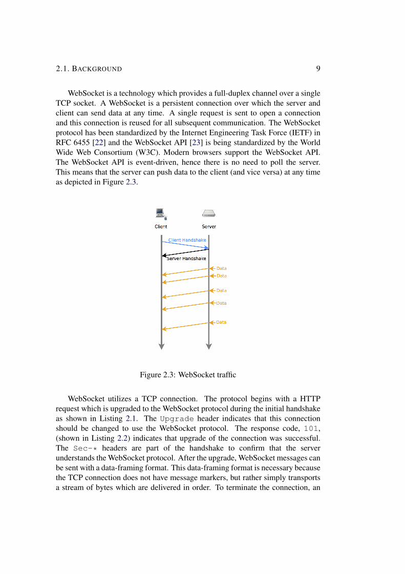
WebSocket is a technology which provides a full-duplex channel over a singleTCP socket A WebSocket is a persistent connection over which the server andclient can send data at any time A single request is sent to open a connectionand this connection is reused for all subsequent communication The WebSocketprotocol has been standardized by the Internet Engineering Task Force (IETF) inRFC 6455 [22] and the WebSocket API [23] is being standardized by the WorldWide Web Consortium (W3C) Modern browsers support the WebSocket APIThe WebSocket API is event-driven hence there is no need to poll the serverThis means that the server can push data to the client (and vice versa) at any timeas depicted in Figure 23
Figure 23 WebSocket traffic
WebSocket utilizes a TCP connection The protocol begins with a HTTPrequest which is upgraded to the WebSocket protocol during the initial handshakeas shown in Listing 21 The Upgrade header indicates that this connectionshould be changed to use the WebSocket protocol The response code 101(shown in Listing 22) indicates that upgrade of the connection was successfulThe Sec- headers are part of the handshake to confirm that the serverunderstands the WebSocket protocol After the upgrade WebSocket messages canbe sent with a data-framing format This data-framing format is necessary becausethe TCP connection does not have message markers but rather simply transportsa stream of bytes which are delivered in order To terminate the connection an
10 CHAPTER 2 WEBSOCKET EXPERIMENTS
endpoint that wants to close the connection sends a numerical code representingthe reason for termination The details of this protocol can be found in theWebSocket Protocol specification [22]
Listing 21 Request to server1 GET chat HTTP112 Host serverexamplecom3 Upgrade websocket4 Connection Upgrade5 Sec-WebSocket-Key dGhlIHNhbXBsZSBub25jZQ==6 Origin httpexamplecom7 Sec-WebSocket-Protocol chat superchat8 Sec-WebSocket-Version 13
Listing 22 Response from server1 HTTP11 101 Switching Protocols2 Upgrade websocket3 Connection Upgrade4 Sec-WebSocket-Accept s3pPLMBiTxaQ9kYGzzhZRbK+xOo=5 Sec-WebSocket-Protocol chat
WebSocket supports sending encrypted traffic over Transport Layer Security(TLS) This is called WebSocket Secure (WSS) TLS is also used in HTTPS toprotect data confidentially and to verify its authenticity
Today many companies providing real-time web solutions take advantageof WebSocket [24 25 26] For instance Xively which is a secure scalableplatform as a service that connects devices with applications provides WebSocketsupport to provide real-time control and data storage [25] In his doctoraldissertation Dominique Guinard proposes to add support for WebSockets to theIoT architecture in order to offer a web based real-time eventing mechanismto communicate with IoT [14] Additional related work about WebSocket isdiscussed in Chapter 2
211 Scaling WebSocket ConnectionsTo support a large number of IoT devices WebSocket servers need to be scaledeither out or up Load balancing solves issues of scalability and availability Loadbalancing has been used since the early days of the Internet In practice thereare two ways of load balancing hardware or software load balancing In thisthesis project I use software load balancing due to the ease of its deploymentwhile its performance is similar to that of hardware load balancing Software load
21 BACKGROUND 11
balancing can be provided by software (bundled as part of an operating system orsoftware installed as an add-on such as HAProxy) HAProxy will be discussed inSection 244
Load balancers can be thought as reverse proxy servers A proxy server isa server acting on behalf of other computers A reverse proxy is a proxy thatprevents direct access to a website by forcing clients to go through the proxyin order to communicate with the website The operation of a proxy server istransparent to the client and the client can only see the proxyrsquos IP address(es) Aforward proxy is a proxy on the clientrsquos side and is placed between the client andInternet The difference between reverse and forward proxies can be seen in theFigure 24
Figure 24 Forward proxy acting on behalf of the client Reverse proxy acting onbehalf of server
Load balancers can make routing decisions based on layer 2 layers 3-4 (IPTCPUDP) or layer 7 (mainly HTTP) As described in the previous section aWebSocket utilizes two protocols HTTP for setting up the connection and TCPfor the actual data exchange (and possibly TLS for security) Therefore theload balancer needs to forward the TCP traffic to an appropriate server withoutbreaking the TCP connection The TCP connection from the client is to the proxyand not directly to the end server Hence a new TCP connection is created betweenthe proxy and the server Therefore the proxy is stateful and must be involved inforwarding all of the traffic flowing from the client to the server Load balancers
12 CHAPTER 2 WEBSOCKET EXPERIMENTS
can utilize one of several algorithms to choose a server to route the TCP traffic toSome algorithms such as round robin or random choice are not deterministic andthey do not use client side information (such as cookies or IP addresses) to pickthe server There are also deterministic algorithms such as sticky sessions thatuse client side information and choose a given server based on this information
Load balancing can also offer many additional benefits such as providing TCPbuffering acting as a firewall and TLSSSL acceleration In the context of thisthesis the main aim of load balancing will be to suitably distribute loads across anumber of servers
22 Related WorkThis section gives a brief overview of previous projects concerning the WebSocketrsquosperformance
Gutwin Lippold and Graham [27] carried out a study to compare theperformance of web-based networking methods used in groupware applicationsThey describe several requirements for different kinds of real-time systems Theyshow that WebSocket can support most groupware systems and suggest thatthe browser should be used by groupware developers Their studies show thatWebSockets can perform better than plug-in approaches such as Java appletsHowever they note that the use of TCP rather than UDP may have latencyproblems in real-world situations due to limited bandwidth and varying trafficpatterns
Greco and Lubbers [28] compare the performance of WebSocket and pollingThey showed that WebSocket reduces HTTP header traffic and has lower networklatency when compared to polling Their experiments showed a 500 to 1 reductionin overhead and a 3 to 1 reduction in latency This latency reduction does notreduce the propagation latency of data as the propagation latency is the same forpolling and WebSocket However the queueing latency (the time that a serverwaits before sending a message) is different In the case of WebSocket the servercan send a message as soon as the message becomes available However in thecase of polling the polling interval determines how long the server must wait for aclientrsquos request All of the reduction in latency results from removing the queuinglatency
Puranik Feiock and Hill [29] quantitatively compared AJAX and WebSocketby integrating them into a distributed real-time embedded system They showthat WebSocket provides higher throughput (21544 more) and better networkperformance (while using 50 less bandwidth) However these results are fortheir example application and there is no guarantee that other applications wouldexperience the same performance
23 GOAL 13
Jomier and Marion [30] present a real-time collaborative visualization toolbased on WebSocket and WebGL Their results show that using WebSocketcompared to AJAX has better performance in terms of lower latency
Autobahn Testsuite [31] is a project to test the correctness of WebSocketprotocol implementations and is based upon over 300 test cases Autobahnincludes some tests to measure the round trip time for different message sizesand fragment sizes
These projects all show that WebSocket performs better than polling interms of providing lower latency and greater user data bandwidth in most casesBuilding on these results this thesis project uses WebSocket to implement agateway architecture for IoT This thesis project describes tests that have beenperformed to measure the scalability and the latency of this architecture in termsof the following metrics throughput message service time (including eventloop latency) response latency and CPU usage The choice of these scalabilitymetrics are mainly based on Greg Barishrsquos book Building Scalable and High-Performance Java Web Applications [32] An article about WebSocket test byCubeia (a software development company focusing on scalability solutions) alsoleads to these same metrics [33]
23 Goal
The goal of these experiments are to stress test the potential WebSocket architecturethat has been proposed to support IoT communication Some benchmarks havealready been used to investigate the scalability of WebSockets [34 35 36 37]Some of these benchmarks use a server that simply echoes incoming messages[35 36] while some use a server which broadcasts each message to all connectedclients [34 37]
Instead of echoing or broadcasting all messages from all connected clients inthe tests described here the clients are separated into two types publishers andsubscribers In this way we can simulate a number of IoT devices which actas publishers sending data to a number of clients that act as subscribers Figure25 shows the case of a publisher and several subscribers Subscribers receivemessages published to those topics to which they subscribe The tests will focuson the costs of sending messages from the publishers to the subscribers using themetrics described in the previous section
The tests follow a quantitative research method with a numerical data analysisand investigate the following
bull How many WebSocket connections can a server support
14 CHAPTER 2 WEBSOCKET EXPERIMENTS
bull How can load balancers be exploited to scale up the numbers of WebSocketconnections that can be supported by a WebSocket architecture
bull What operations create a bottleneck Is opening connections holdingconnections open simultaneously or sending messages the limitation of aWebSocket server
bull How does the CPU usage of servers change during WebSocket communication
This thesis project does not give a comparative analysis of different technologiesfor server side programming languages or load balancers (A comprehensiveproject comparing the performance of different server side technologies has beendone as part of the TechEmpower web application framework benchmarks project[38]) Instead this thesis investigates a proposal for a scalable architecture thatcan support a number of IoT devices by presenting data showing the limits of thisarchitecture
Figure 25 Publishers and subscribers
24 Tools and Experimental SetupThis section presents the tools used in the tests The section begins with adescription of a number of a useful command line tools then describes the othersoftware that was used for testing This section also describes the steps taken tosetup an experimental environment in order to perform these tests
241 Command Line ToolsA number of command line tools were used for the tests specifically SSHsar kSar git ntp and gnuplot Each of these is briefly described below The
24 TOOLS AND EXPERIMENTAL SETUP 15
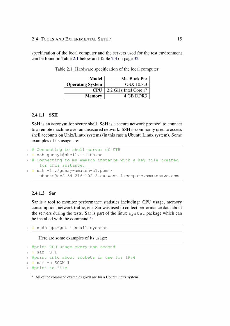
specification of the local computer and the servers used for the test environmentcan be found in Table 21 below and Table 23 on page 32
Table 21 Hardware specification of the local computer
Model MacBook ProOperating System OSX 1083
CPU 22 GHz Intel Core i7Memory 4 GB DDR3
2411 SSH
SSH is an acronym for secure shell SSH is a secure network protocol to connectto a remote machine over an unsecured network SSH is commonly used to accessshell accounts on UnixLinux systems (in this case a Ubuntu Linux system) Someexamples of its usage are
1 Connecting to shell server of KTH2 $ ssh gunaykshellitkthse3 Connecting to my Amazon instance with a key file created
for this instance4 $ ssh -i gunay-amazon-s1pem
ubuntuec2-54-216-102-8eu-west-1computeamazonawscom
2412 Sar
Sar is a tool to monitor performance statistics including CPU usage memoryconsumption network traffic etc Sar was used to collect performance data aboutthe servers during the tests Sar is part of the linux systat package which canbe installed with the command lowast
1 $ sudo apt-get install sysstat
Here are some examples of its usage
1 print CPU usage every one second2 $ sar -u 13 print info about sockets in use for IPv44 $ sar -n SOCK 15 print to file
lowast All of the command examples given are for a Ubuntu linux system
16 CHAPTER 2 WEBSOCKET EXPERIMENTS
6 $ sar -n SOCK -o resultssar 17 read the file to extract info about sockets8 $ sar -n SOCK -f resultssar9 read the file to see memory cpu utilization
10 $ sar -f resultssar11 put the sar data into file12 $ sar -o resultssar 1 gtdevnull 2gtamp1 amp
2413 kSar
kSar [39] is a Java based tool to graph the output of sar It can export the graph ina variety of formats such as PDF JPEG etc This tool can be used as shown withthe following commands
1 print sar data to a text file by using C locale2 $ LC_ALL=C sar -f ˜datafile -A gt sartxt3 execute kSar with the sartxt file given as input and
sarpdf as output4 $ java -jar kSarjar -input sartxt -outputPDF sarpdf
2414 Git
Git is an open source distributed version control system developed by LinusTorvalds The purpose of Git is to store all versions of the source codeand easily access any past version While Git can be used locally a remote(centralized) repository is needed to protect against data loss GitHub is apopular service for Git repositories [40] Git and GitHub were used to providea backup and to maintain a complete history of the software development forthis project Git was also used to push the local code to the test servers Allthe code for these experiments can be found in the public GitHub repositoryhttpsgithubcomgmertk [41] The most frequently used commands during thisproject were
1 to initialize a Git repository which is a hiddendirectory in the folder where Git is executed
2 $ git init3 to add and commit changed files into the repository4 $ git commit -am message5 to add a remote repository to push the local repository6 $ git remote add origin
httpsgithubcomgmertkwebsocket-test
24 TOOLS AND EXPERIMENTAL SETUP 17
7 to push the local changes to the remote repositorycalled origin
8 $ git push -u origin master9 to check for changes on the GitHub repository and pull
any new changes10 $ git pull
2415 NTP
To synchronize the clocks of each of the computers the Network Time Protocol(NTP) [42] was used The NTP daemon synchronizes the local systemrsquos time witha remote server
To install this NTP daemon the following command can be used
1 $ sudo aptitude install ntp
After installation the daemon can be started or stopped with the followingcommands (as usual for Linux services)
1 $ sudo etcinitdntp start2 $ sudo etcinitdntp stop
In the tests one of the servers was chosen as master NTP server and theother servers synchronize to this master to guarantee that all of the servers havetheir time set to the same value The advantages of this setup are a reducednumber of outgoing connections [43] The master NTP server was configuredto synchronize with a stratum 1 server (nist1-sjWiTimenet) etcntpconffile was configured to set the server addresses Before the tests the time differencebetween the servers was below 1 ms as established from the output of the ntpq-p command
2416 Gnuplot
Gnuplot [44] is a widely used and powerful tool to generate plots of data It canexport the plot in a variety of formats such as PNG JPEG etc The test resultspresented in Section 26 were plotted using gnuplot
242 NodeJS Server
Nodejs is an event-driven non-blocking infrastructure for building highly concurrentsoftware It is used by many large companies to create fast and scalable networked
18 CHAPTER 2 WEBSOCKET EXPERIMENTS
services [45] Nodejs is written in JavaScript and it provides elegant APIs and hasa large number of third-party modules available for it
Event-driven programming is a programming model where events determinethe flow of the program Events are handled by callbacks which are functionsthat are invoked when an event happens such as when a connection occursor when a database query produces a result The example below shows howevent-driven programming is different from traditional blocking inputoutput (IO)programming [46] In traditional blocking IO programming a database querystops the current process until the database processing is completed
1 result = query(rsquoSELECT FROM users WHERE name = mert rsquo)2 log(result)
In event-driven systems logging this query would be written as
1 queryFinished = function(result) 2 log(result)3 4 query(rsquoSELECT FROM users WHERE name = mertrsquo
queryFinished)
In the event-driven approach when the query has completed the callbackqueryFinished function will be called This model of programming is calledevent-driven or asynchronous programming Event-driven programming is oneof the defining features of Nodejs JavaScript is well suited for event-drivenprogramming because it supports closures and functions as arguments
Event-driven programming is realized by having an event loop which detectsevents and invokes callbacks when a specific type of event happens An eventloop is simply a thread running inside a process thus when an event happens theevent handler runs without requiring an interrupt In this model at most one eventhandler is running in a process at any given time thus the programmer does nothave to consider concurrent threads of execution changing the shared memorystate as they would have to do in multi-threaded programming However thisalso is a limitation since only one handler is running and it runs to completion -therefore other events have to wait until this event handler has voluntarily givenup the CPU
Nodejs can be installed on Ubuntu via the package manager apt-get byentering the following commands
1 $ sudo apt-get install -y python-software-properties2 this command installs the latest stable version from
Chris Learsquos Ubuntu Personal Package Archives (PPA)3 node v0105 was the stable version when I performed the
24 TOOLS AND EXPERIMENTAL SETUP 19
experiments4 $ sudo add-apt-repository ppachris-leanodejs5 $ sudo apt-get update6 npm is the node package manager to install third-party
modules7 $ sudo apt-get install -y nodejs npm
Nodejs has many packaged modules which can be installed via the npmpackage manager The modules that have been used in our testing are OptimistGauss Socketio Websocket-worlize Forever and Node-redis Each of them isdescribed in more detail below
Optimist ndash Optimist is a Nodejs module for simple option parsing Withoptimist options are similar to a dictionary An example from the optimist website[47] is shown below The file shortjs contains
1 usrbinenv node2 var argv = require(rsquooptimistrsquo)argv3 consolelog(rsquo(dd)rsquo argvx argvy)
1 $ shortjs -x 10 -y 21
To install
1 $ npm install optimist
Gauss ndash Gauss makes it easy to calculate and explore collected data byproviding functions for data analysis such as standard deviation and arithmeticmean [48]
To install
1 $ npm install gauss
Socketio ndash Socketio is a popular JavaScript library which simplifies theusage of WebSocket and provides fail-overs to other protocols such as AdobeFlashsockets JSONP polling and AJAX long polling It also offers heartbeatstimeouts and disconnection support none of which the WebSocket API providesdirectly Initially the testing used Socketio because I thought Socketio was betterbecause of its support of old browsers and it provided a better abstraction fornative WebSocket API However I subsequently realized that the Socketio libraryhas a significant problem which causes it to disconnect clients when there was alarge number of connections [49] Unfortunately this issue is not fixed yet so Ichanged to another WebSocket library (Websocket-worlize - described next)
20 CHAPTER 2 WEBSOCKET EXPERIMENTS
Websocket-worlize ndash Websocket-worlize is a pure JavaScript implementationof WebSocket for NodeJS It provides both a WebSocket server and client libraryI chose to use this library because of its pure design and interoperability with loadbalancers
To install
1 $ npm install websocket
The following commented example for an echo server is modified from themodulersquos documentation [50]
1 usrbinenv node2 var WebSocketServer = require(rsquowebsocketrsquo)server3 var http = require(rsquohttprsquo)4
5 var server = httpcreateServer(function(request response)
6 consolelog prints on the command line7 consolelog((new Date()) + rsquo Received request for rsquo +
requesturl)8 responsewriteHead(404)9 responseend()
10 )11 serverlisten(8080) Start the server listening on TCP
port 808012
13 wsServer = new WebSocketServer(14 httpServer server15 )16
17 Here we can see a clear example of event-drivenprogramming
18 When a request occurs call the function to open aWebSocket
19 wsServeron(rsquorequestrsquo function(request) 20 var connection = requestaccept(rsquoecho-protocolrsquo
requestorigin)21 consolelog((new Date()) + rsquo Connection acceptedrsquo)22
23 When a message arrives call the function to echo it24 connectionon(rsquomessagersquo function(message) 25 Message type can be text or binary26 if (messagetype === rsquoutf8rsquo) 27 consolelog(rsquoReceived Message rsquo +
24 TOOLS AND EXPERIMENTAL SETUP 21
messageutf8Data)28 connectionsendUTF(messageutf8Data)29 30 else if (messagetype === rsquobinaryrsquo) 31 consolelog(rsquoReceived Binary Message of rsquo +
messagebinaryDatalength + rsquo bytesrsquo)32 connectionsendBytes(messagebinaryData)33 34 )35
36 When the socket is closed call the followingfunction
37 connectionon(rsquoclosersquo function(reasonCodedescription)
38 consolelog((new Date()) + rsquo Peer rsquo +connectionremoteAddress + rsquo disconnectedrsquo)
39 )40 )
Forever ndash Simply running Nodejs scripts with the node command the serverwill start as a process that will block the current shell until the process crashes or iskilled To run the server in the background a forever module is used Its purposeis simply to run the server script continuously If a flag is set when the module isinvoked then the forever module can also automatically restart the script in caseof an exception
To install
1 $ sudo npm install forever -g
An example of using the forever module is
1 in case of crash restart the script a maximum of 3 times2 $ forever -m 3 simplejs
Node-redis ndash Redis [51] a key-value store will be discussed in section 245This is a complete Redis client for Nodejs which supports all Redis commandsInstallation
1 $ npm install redis
The publisher-subscriber (pub-sub) architecture was introduced in the beginningof this chapter A simple example of a publisher-subscriber service is
1 var redis = require(redis) client1 =
22 CHAPTER 2 WEBSOCKET EXPERIMENTS
rediscreateClient() client2 = rediscreateClient()2
3 When client1 subscribes to the channel client2starts to publish messages to this channel
4 client1on(subscribe function (channel count) 5 client2publish(a channel a message)6 )7
8 When client1 gets a message from the channel itlogs those messages
9 client1on(message function (channel message) 10 consolelog(client1 channel + channel + +
message)11 )12
13 Client1 subscribes to the channel14 client1subscribe(a channel)
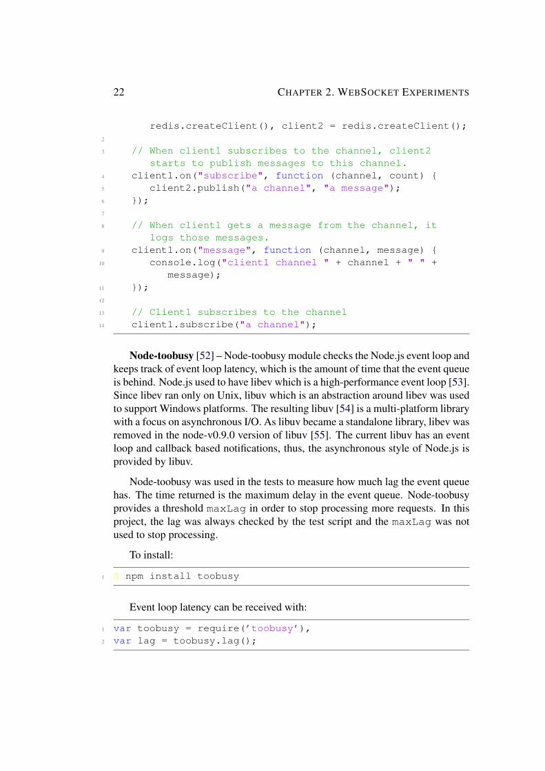
Node-toobusy [52] ndash Node-toobusy module checks the Nodejs event loop andkeeps track of event loop latency which is the amount of time that the event queueis behind Nodejs used to have libev which is a high-performance event loop [53]Since libev ran only on Unix libuv which is an abstraction around libev was usedto support Windows platforms The resulting libuv [54] is a multi-platform librarywith a focus on asynchronous IO As libuv became a standalone library libev wasremoved in the node-v090 version of libuv [55] The current libuv has an eventloop and callback based notifications thus the asynchronous style of Nodejs isprovided by libuv
Node-toobusy was used in the tests to measure how much lag the event queuehas The time returned is the maximum delay in the event queue Node-toobusyprovides a threshold maxLag in order to stop processing more requests In thisproject the lag was always checked by the test script and the maxLag was notused to stop processing
To install
1 $ npm install toobusy
Event loop latency can be received with
1 var toobusy = require(rsquotoobusyrsquo)2 var lag = toobusylag()
24 TOOLS AND EXPERIMENTAL SETUP 23
243 Amazon Web Services
This section describes how the Amazon instances were created for running thetests described in section 25 I chose to use Amazon Web Services (AWS) due toits affordable prices and popularity AWS is an infrastructure-as-a-service (IAAS)provider where a virtualized computer is rented Virtualization enables a singlecomputer with eight processors to seem like eight independent computers or evenmore - since the hypervisor (Xen in AWS) can be running many virtual machinesper physical processor
There are many AWS terms that the reader should be familiar with beforegoing further in this thesis These include
EC2 ndash Amazon Elastic Compute Cloud (EC2) is a web service to launchand manage LinuxUNIX and Windows server instances in one of Amazonrsquos datacenters
AMI ndash Amazon Machine Image (AMI) is a snapshot of a (virtual) computerrsquosroot drive These images contain the operating system installed software andconfiguration files When a virtual machine instance is launched it is launchedfrom an AMI
Security groups ndash A security group defines a set of protocols ports and IPaddress ranges to define firewall rules for instances Several instances can use thesame security group For the purpose of the tests described in this thesis a securitygroup was created that allows SSH HTTP and NTP connections
Key pair ndash A key pair is essential for communicating with a fresh instancewhen it is launched A SSH key pair with a public key is stored in the instancewhile the private key is stored in my local computer More information aboutpublic key cryptography can be found in the book ldquoSSH The Secure Shell TheDefinitive Guiderdquo [56]
Regions and availability zone ndash AWS resources are located in differentregions (such as EU West - Ireland US West - California etc) A regioncomprises at least two availability zones which are distinct locations within aregion in order to make the infrastructure more resilient to power failures andnetwork outages
2431 Problems with Virtualization
While the virtual computers have reasonable performance their performance isworse than that of native hardware Wang and Ng carried out a study to analyzethe impact of virtualization on the network performance of Amazon EC2 [57]Their measurement shows that virtualization can cause throughput instability andabnormal delay variations especially on EC2 small instances due to processorsharing In the virtualized EC2 the delay caused by virtual machine scheduling
24 CHAPTER 2 WEBSOCKET EXPERIMENTS
can be much larger than the other delay factors such as propagation delay androuter queuing delay Their analysis concludes that virtualization and processorsharing cause unstable network performance
Another issue is that AWS does not guarantee that the instance is not placedwith a noisy neighbor The virtual machines that work on the same hardware maysteal other virtual machinesrsquo share of the physical CPU This is called the noisyneighbor problem and can be measured with ldquoSteal Timerdquo in CPU statistics Noisyneighbors may also cause abnormal and variable performance
Although AWS is subject to these kinds of problems this thesis project usesAWS due to its affordable prices and ease of scaling up and out High capacityinstances were chosen to reduce the problems and in the tests thus the ldquoStealTimerdquo was measured to always be under 2 for the instances that were used inthe measurements described later in this thesis
2432 Setting Up Servers
To start using an AWS cloud computer is pretty straightforward One goes tothe AWS website (awsamazoncom) and creates an account Then using themanagement console the user launches a new EC2 instance for example aninstance of Ubuntu Server 12042 LTS (The next section will give a detailedspecification of the instances that were used for testing) Next using themanagement console the user creates a key pair for use with SSH One connectsto the instance using SSH and installs the software that he or she wants to run inthis case the required tools for the tests were installed After installing these toolsan image of this instance (ie an AMI) can be created in order to easily instantiatefurther instances Four custom AMIs were created with different configurationsand tools one for application servers one for client servers one for a loadbalancer and another for a persistence (ie stable storage) layer
Application Server and Client Server instances each included Git sarNodejs and the Nodejs modules introduced above Some customizationswere done on these servers For example each TCP connection has a filedescriptor open in the file operating system It is important to set the limit of thenumber of such open files to a value larger than what will be needed during testingBy default Ubuntu only allows 1024 file descriptors to be open at any one timeThis number of open file descriptors is insufficient for stress testing purposes Toset this limit permanently in Ubuntu the file etcsecuritylimitsconfis modified to include the lines shown below [58] The value has been set to a verylarge number so that these limits will not be a bottleneck in the tests Howeverthis is for stress testing purposes and may not suitable for a production serverBecause this number of sockets will use a large amount of memory which is notswappable this large number of sockets may decrease the actual performance of
24 TOOLS AND EXPERIMENTAL SETUP 25
the server with respect to an optimally tuned server
1 soft nofile 9999992 hard nofile 999999
After restarting the instance the new limit can be displayed with the commandsbelow
1 $ ulimit -a2 $ ulimit -n
The ulimit -a command reports all limits such as maximum file size maximumsize of virtual memory etc The ulimit -n command only reports the maximumnumber of file descriptors
To avoid limitations of the operating systemrsquos default settings and to improvegeneral performance some other system options are tuned by editing theetcsysctlconf file These options are used for the purpose of stresstesting [59] and can be found in Appendix A
The load balancer instance included sar and HAProxy Further details ofHAProxy will be given later in section 244
The Redis layer instance in addition to sar has Redis installedTo simulate a large number of clients on one machine is not a realistic
approach Because that machinersquos limitations in terms of memory CPU ornetwork throughput will limit the load that it can generate The Bees with MachineGuns tool was used to create a number of instances to simulate clients
Bees with Machine Guns [60] is a tool to create and control EC2 instancesremotely It enables the user to run any number of clients (bees) immediately andexecute commands on them The tool is implemented as a python program andcan be installed by the python package manager pip
1 $ pip install beeswithmachineguns
A typical bees usage is
1 Create 10 instances in the region called us-east-1a2 Use the default security group the pem file called
beeskeypair and the AMI called ami-621b630b3 Login with the user name ubuntu4 $ bees up -s 10 5 -g default 6 -k beeskeypair 7 -i ami-621b630b 8 -z us-east-1a
26 CHAPTER 2 WEBSOCKET EXPERIMENTS
9 -l ubuntu 10 Execute the command node loadjs in all of the
instances and prints the output to responsetxt11 $ bees exec -o responsetxt - node loadjs12 Terminate all of the instances13 $ bees down
244 Load Balancer HAProxyHAProxy [61] is a high-performance software based TCP and HTTP loadbalancer It has been used by the biggest companies in the industry such asTwitter Instagram etc [62] HAProxy is very configurable and provides manyload balancing algorithms including roundrobin leastconn and more[63] Detailed documentation about this load balancer can be found on HAProxyrsquoswebsite [64] HAProxy was installed on the load balancer instance with thefollowing commands
1 get HAProxy version 152 $ wget
httphaproxy1wteudownload15srchaproxy-15-dev18targz3 $ tar -zxf haproxy-15-dev18targz4 $ cd haproxy-15-dev185 build and install6 $ make7 $ cp haproxy usrsbinhaproxy
The configuration file haproxycfg was modified and the HAProxy wasrestarted
1 $ sudo vim etchaproxyhaproxycfg2 to restart3 $ sudo service haproxy start4 or5 $ sudo haproxy -f etchaproxyhaproxycfg
The configuration file used in the tests can be found in Appendix B This filehas several sections that are of interest to us
global Parameters in this section are process wide and global settings for theconfiguration
defaults This is the section where common parameters are set for all othersections
24 TOOLS AND EXPERIMENTAL SETUP 27
frontend Incoming client connections are listened to in frontend sections
backend Backend is a section which is used to define a list of servers to be usedwith a load balancing algorithm health check configurations etc Incomingconnections are forwarded to these servers
listen Listen sections are a combination of frontend and backend sections
A simple configuration file from the HAProxy wiki [65] is shown below
1 An HTTP proxy listening on port 80 in all interfaces2 and forwards requests to a single backend called
servers with a3 single instance called server1 listening on
12700180004 global5 daemon6 maxconn 256 is the maximum number of concurrent
connections The number is chosen randomly for thisexample
7 frontend http-in8 bind 809 default_backend servers
10 backend servers11 server server1 1270018000 maxconn 256
As shown in the previous chapter a WebSocket starts as a HTTP request suchas the one shown below
1 GET HTTP112 Upgrade websocket3 Connection Upgrade4 Sec-WebSocket-Version 135 Sec-WebSocket-Key dGhlIHNhbXBsZSBub25jZQ==6 Host localhost80807 Sec-WebSocket-Protocol echo-protocol
The ConnectionUpgrade and Upgradewebsocket headers tell theserver to change to the WebSocket protocol When the server acknowledges witha status code 101 the TCP connection used for the HTTP request is re-used forthe WebSocket data exchange The HAProxy is able to switch a connection fromHTTP to TCP without breaking the TCP connection and HAProxy implementstimeouts for both protocols During the first request and response the HAProxyacts as a HTTP server When the HAProxy detects the ConnectionUpgrade
28 CHAPTER 2 WEBSOCKET EXPERIMENTS
header line it switches to being a TCP proxy when the server responds with asuccess code From that point on the HAProxy simply operates in tunnel modeand does not analyze or interact with the coming TCP data stream it simplyforwards the data stream
This behavior is configured in the config file by using the lines below Theaccess control list (acl) keyword defines a test criteria with sets of values and theproxy only performs actions if the criteria is true
1 acl ws_upgrade hdr(Upgrade) -i WebSocket2 use_backend ws if ws_upgrade
There are several other ways that the HAProxy can proxy WebSocket connections[66] specifically URI based and sub-domain based
URI based ndash HAProxy can direct the traffic based on the URI such asexamplecomwebsocket This is actually a path based means of identifyingwhich traffic to proxy An example is
1 acl ws_uri path_beg -i websocket2 use_backend ws if ws_uri
Sub-domain based ndash If the server for WebSocket connections is in a separatesub-domain then HAProxy can direct connections for this specific sub-domain toa server An example for the domain websocketexamplecom is
1 acl ws_subdomain hdr_end(host) -i websocketexamplecom2 use_backend ws if ws_subdomain
For the purposes of our tests the WebSocket detection method was configuredThis approach was selected because I did not have any subdomains or specificURIs to use for the test setup
Another well-known load balancer is Nginx HAProxy and Nginx are similarin terms of performance [67] However Nginx only started to support WebSocketsin its later versions [68]
245 Redis Layer
In order to reliably send messages to users across servers a layer was needed toallow asynchronous messaging Redis was used as a pub-sub service as it nativelysupports pub-sub operations Redis is a key-value in-memory persistent data storeWhile Redis holds all the data in memory it can write this data to disk for truepersistence Based on how many keys have changed Redis writes the memory todisk In addition to a pub-sub service Redis actually provides five data structures
25 DATA COLLECTION 29
strings sets lists hashes and sorted sets Further details can be found in theRedis reference documentation [69]
Redis has two kinds of persistence modes Snapshotting mode and appendonly mode Snapshotting mode produces snapshots of the data when someconfigured conditions occur For example Redis can be configured to create asnapshot every N seconds if there are at least M changes in the data Snapshots arecreated as rdb files thus this mode is also known as RDB (Redis database) Theappend only mode logs every write operation to an append-only file (AOF) andthis log is re-played when Redis is restarted Both of these modes have their ownadvantages and disadvantages For more information see the Redis persistencedocumentation [70] In the tests described in this thesis Redis is used only as in-memory database and the persistence was disabled by removing the save lines inthe configuration file etcredisredisconf This is because Redis wasused only for its pub-sub service ie without any persistence
In order to install and use Redis one enters the following commands into apersistence layer instance
1 In the tests Redis v2614 was used2 $ wget
httpdownloadredisioreleasesredis-2614targz3 $ tar xvzf redis-stabletargz4 $ cd redis-stable5 $ make6 Starts Redis server7 $ redis-server
During the tests the Redis instance was monitored by redis-stat tool [71]This tool is is based on Redisrsquos INFO command [72] and does not affect theperformance of the Redis instance
25 Data Collection
This section explains how WebSocket connections were tested and how the datawas collected
251 Test Scripts
There were two Nodejs scripts loadjs and appjs Each of these scriptswill be described in detail in the paragraphs below
30 CHAPTER 2 WEBSOCKET EXPERIMENTS
2511 loadjs
The load script is designed to simulate an IoT device which generates messagesand publishes these messages at a configurable frequency to a subscriber Thescript creates a number of publishers and a subscriber per publisher The scriptsends messages via each publisherrsquos connection and messages are received viaeach subscriberrsquos connection
The script is executed with a command such as
1 $ node loadjs -t 2 -n 100 -h localhost -p 8080
The command above creates 100 publishers and one subscriber per publisherwhere each individual publisherrsquos connection publishes a message every 2seconds After each connection is established the publishers starts publishingmessages In this example these numbers were chosen simply to explain theparameters of the script The -h and -p options specify the serverrsquos IP addressand port number to use for initiating a connection The script calculates the latencyof receiving messages from the publisher This latency is the time for a message topropagate from a publisher to a subscriber Each subscriber extracts a timestampfrom the message and calculates the time difference between this timestamp andthe time when this message was received
The messages sent by publishers are JSON objects (converted to a string by theJSONstringify method) These messages represent information that couldbe sent to IoT devices The message format used in the tests is simple and containsonly a timestamp and a subject of the publisher However Activity Streams [73]could also be used as a generic JSON format to describe an IoT activity in order toprovide more data The Activity Streams format can utilize information from anIoT for other web services and this format has been adopted by major companiessuch as Google MySpace etc [73]
The JSON message format used in the tests is
1 2 type publisher3 subject subject00001 Each publisher has a
different subject The 0rsquos are inserted to havea constant message size (70 bytes)
4 published +new Date()5
An example for Activity Streams is
25 DATA COLLECTION 31
1 2 published +new Date() Unix Timestamp3 actor 4 objectType sensor5 id 13761180683256 displayName Temperature Sensor7 8 verb post9 object
10 value 2511 unit C12 13
2512 appjs
The server script is the main application which is executed in the applicationservers The script receives publisher messages and forwards these messagesto subscribers with the help of Redis The script logs the event timestamps tocalculate the message service time and loop latency The IP address and portnumber of the Redis server are the only parameters
1 $ node appjs -h localhost -p 6379
The parameters of all of the scripts are listed in Table 22
Table 22 Parameters of the scripts
loadjs
-t Message period in seconds-n Number of publishers-h Address of application server-p Port of application server
appjs -h Address of Redis server-p Port of Redis server
252 Test ServersThe scripts are executed in EC2 instances having the specifications shown inTable 23 The details of the HAProxy and Redis servers are also presented inthis table More information about these types of instances can be found in theEC2 documentation [74] According to Amazon ldquoThe amount of CPU that is
32 CHAPTER 2 WEBSOCKET EXPERIMENTS
allocated to a particular instance is expressed in terms of these EC2 ComputeUnits (ECU) One ECU provides the equivalent CPU capacity of a 10-12 GHz2007 Opteron or 2007 Xeon processorrdquo [74] The reason for locating the clientsin another site was to increase the communication delay to a value that would bemore representative of an actual usage case It would be unrealistic to limit thelocation of the IoT devices to being within a single cloud data center The clientinstances were chosen larger than the application instances to ensure that the testsare not limited by the number of client instances which generate the load Twoclient instances were used and in Section 266 it can be seen that this number ofclient instances were sufficient to generate the target load
Table 23 Specification of the Instances
Instance Family Type ECU Memory(GiB)
Region
Client instances General purpose m32xlarge 26 30 US EastApplication instance General purpose m1large 4 75 US West
HAProxy instance General purpose m1large 4 75 US WestRedis instance Memory optimized m2xlarge 65 171 US West
Operating system of the all instances is Ubuntu Server 12042 LTS
253 TestingAn IoT device might be anything an accelerometer a gyroscope a thermostat alight bulb etc Depending on the aim of the device the message rate of the devicemay vary a lot The IoT Strategic Research Roadmap report [75] anticipatesthat IoT devices could be generating a large number of updates such as 10000messages per person per day Priyantha et al [76] prototyped an application forhome energy management and they observed that sensor states for motion sensorsand power sensors change only 2 to 20 times a day that is one message every 100minutes to 10 minutes Xively [25] a cloud service for IoT offers pricing planswith different limits of update rates varying from 10 to 01 updates per minuteThese projects show that IoT devicesrsquo domain is very large and that message ratesdepend on the usage domain of the device In the tests done for this thesis themessage rate is 4 Hz per publisher (as specified in the article of Pimentel andNickerson ldquoCommunicating and Displaying Real-Time Data with WebSocketrdquo[77])
Testing started with one application server When this single server hit its CPUlimit a load balancer was added and the same tests were repeated with two serversThis pair of tests enabled us to examine the effects of scaling the number of servers
25 DATA COLLECTION 33
up from one to two Four performance metrics were generated throughput (interms of number of processed messages) message service time (including eventloop latency) response time and CPU usage
During these tests the server(s) were monitored with the sar tool to examinethe CPU usage and to know whether the server was overloaded by the arriving anddeparting messages
To execute all test cases a small bash script (testsh) was written This bashscript executes loadjs script with a different number of publishers during thetest When all of the publishers and subscribers are connected the publishersstart to send messages Latency data is collected for 5 minutes as suggested inNottinghamrsquos blog post [78] and then all connections are closed before startinga new test with an increased number of connections The time between each testcase was 1 minute in order to have no TCP connections in a timewait state Thetest was stopped when the application servers had no idle CPU capacity
To execute the test shell into the client servers which create the load thefollowing command is used
1 Server to be loaded is given as a parameter to testsh2 $ bees exec -o responsetxt - testsh
ec2-54-228-107-60eu-west-1computeamazonawscom
34 CHAPTER 2 WEBSOCKET EXPERIMENTS
26 Data AnalysisThis section presents the data that was collected and analyzes the results of thetests that were carried out The presentation is in six subsections correspondingto the four performance metrics number of commands processed by the Redisserver and number of events created by the clients The four performance metricsare throughput message service time (with event loop latency) response time andCPU usage The number of commands processed by Redis server was collectedby using redis-stat tool (mentioned in Section 245) Each subsection comparestwo cases (case 1) the case without a load balancer (ie a single server) and (case2) the case with a load balancer and two servers
261 ThroughputThe load was created by the load script with each publisher sending four messages(corresponding to four message events in the application server) per second Forexample for 1000 publishers there will theoretically be a maximum of 4000message events per second Figure 26 shows the measured number of eventsduring the test of a single server while Figure 27 shows the case with a loadbalancer and two servers It can be seen that a single server starts to diverge froman ideal system at roughly 800 publishers while the load balanced servers start todiverge at 1600 publishers The deviation in number of events starts to increase asthe number of publishers increases These critical points should be considered forthe other metrics that are described in the following sections Note that the x-axisof each of these two figures shows the time in seconds since the start of the testshscript As stated in section 253 each test ran for 5 minutes (ie 300 seconds) andwas separated from the next test by 1 minute (ie 60 seconds)
The statistics of the results are presented in Tables 24 and 25 For the singleserver when the number of publisher increased the difference between mean andexpected number of events increases (except for the case for 1000 publisherswhich has some outliers as seen in Figure 26) The difference between theaverage of actual events and expected events is at most 13 However the standarddeviation increases up to 1387 for 1400 publishers This increase in deviation willresult in an unstable user experience For the load balanced servers the differencebetween the expected and mean number of events is less than 3 until reaching 1800publishers After this point the difference starts to increase If the load balancedservers are compared to a single server for the same number of publishers it can beseen that load balanced servers provide better performance in terms of the numberof events that are successfully being processed Apparently it is due to the sharingof the load between the two servers
As seen in Figures 26 and 27 there are cases with more than the expected
26 DATA ANALYSIS 35
numbers of events When the events in the event queue of Nodejs starts to buildup (because the arrival rate is faster than the processing rate) then the events inthe queue may be processed in the event looprsquos next cycle where there may be lesswork to do This unstable number of events in the event queue is because of theoverloaded CPU
Figure 26 Message events for case 1
Figure 27 Message events for case 2
36 CHAPTER 2 WEBSOCKET EXPERIMENTS
Table 24 Number of events per second for case 1
Publishers Expected Events Actual Events200 800 800400 1600 1599plusmn11600 2400 2399plusmn8800 3200 3198plusmn68
1000 4000 3987plusmn4351200 4800 4793plusmn3091400 5600 5587plusmn1387
Table 25 Number of events per second for case 2
Publishers Expected Events Actual Events200 800 800400 1600 1599plusmn5600 2400 2399plusmn10800 3200 3199plusmn38
1000 4000 3999plusmn191200 4800 4798plusmn851400 5600 5598plusmn1181600 6400 6399plusmn2051800 7200 7197plusmn3552000 8000 7993plusmn3312200 8800 8784plusmn5322400 9600 9582plusmn7792600 10400 10357plusmn19932800 11200 10974plusmn1681
262 Message Service Time and Event Loop LagFigure 28 and 29 show the mean and median of the message service time whichincludes the queueing time and the time spent in the Redis layer For a singleserver message service time starts to increase at 800 publishers The differencebetween mean and median also increases due to large outliers An exponentialgrowth is seen after 1200 publishers For two servers the service time starts toincrease at 1600 publishers because of the shared load As seen in the previousthroughput metric the critical point is 800 publishers for the single server and1600 publishers for two servers At these critical points the message service timedeviates from a constant value Figures 210 and 210 show the event loop lag
26 DATA ANALYSIS 37
measured by the node-toobusy module Until 1000 publishers the loop lag doesnot show a large growth At 1200 publishers the mean loop lag increases up to500 ms and later it increases exponentially This increase in loop lag effects themessage service time as seen in Figures 28 and 29
Figure 28 Message service time for case 1
Figure 29 Message service time for case 2
38 CHAPTER 2 WEBSOCKET EXPERIMENTS
Figure 210 Event loop lag for case 1
Figure 211 Event loop lag for case 2
Tables 26 and 27 present the statistics of message service time for eachtest case With single server the message service time is around 1 ms until 800publishers At 800 publishers the mean time of message service time reaches to166 ms from 25 ms This increase is also observed in standard deviation andmedian This is because the servers starts to be overloaded At 1400 the meanmessage service time is reaching to around 4 second which is already beyond to
26 DATA ANALYSIS 39
the requirement of 1 second response delay There is a large standard deviationafter the server is overloaded This implies that the delay will be unstable Fortwo servers the results generates a similar statistics but with the doubled numberof publishers
Table 26 Message service time statistics for case 1
Publishers Average (ms) Median (ms)200 147plusmn060 1400 220plusmn121 1600 253plusmn135 1800 16585plusmn9641 119
1000 24984plusmn15641 1391200 31416plusmn26719 1741400 380655plusmn182216 1311
Table 27 Message service time statistics for case 2
Publishers Average (ms) Median (ms)200 087plusmn031 1400 134plusmn050 1600 184plusmn109 1800 203plusmn121 1
1000 235plusmn120 11200 260plusmn134 11400 1947plusmn1066 101600 17453plusmn9412 1121800 20044plusmn9893 1182000 25154plusmn14724 1322200 27913plusmn20645 1512400 41806plusmn28385 2442600 250313plusmn189019 10912800 390606plusmn201342 1391
The statistics of the event loop lag are presented in Tables 28 and 29 For asingle server no event loop lag is observed at 200 and 400 publishers At 600publishers there is a negligible lag of 022 ms of average However at 800publishers the mean loop lag shows a large increase of up to 100 ms This isthe critical point as seen in the previous metrics This increased loop lag and alsothe increased message service time will cause an increase in the response time
40 CHAPTER 2 WEBSOCKET EXPERIMENTS
For two servers as expected there is no loop lag until 1000 publishers At 1000and 1200 publishers the loop lag is less than half a millisecond Then the looplag starts to increase as in the case of a single server At 2800 publishers a largeexponential increase is observed up to around 4 seconds
Table 28 Event loop lag statistics for case 1
Publishers Average (ms) Median (ms)200 0plusmn0 0400 0plusmn0 0600 022plusmn012 0800 9939plusmn9215 93
1000 10441plusmn10183 991200 49003plusmn40852 851400 481012plusmn370852 1023
Table 29 Event loop lag statistics for case 2
Publishers Average (ms) Median (ms)200 0plusmn0 0400 0plusmn0 0600 0plusmn0 0800 0plusmn0 0
1000 028plusmn025 01200 038plusmn018 01400 394plusmn123 01600 3051plusmn2368 101800 4041plusmn3931 252000 9461plusmn7137 572200 23620plusmn25412 652400 50216plusmn40562 2012600 81010plusmn60635 4232800 388789plusmn340153 1108
Nodejs is single-threaded and scheduling of tasks are handled with a queueThe latency increases with the number of messages waiting in the serverrsquos queue tobe processed when messages arrive at a faster rate than the processor can processthese messages To calculate the queue size at a certain rate Littlersquos Law can beused Littlersquos Law says that the average number of items in a queuing system
26 DATA ANALYSIS 41
equals the average rate at which items arrive multiplied by the average time thatan item spends in the system [79]
L = λW (21)
L Average number of items in the queuing system
W Average service time in the system for an item
λ Average number of items arriving per unit time
Littlersquos Law can be used to estimate the average queue length for the singleserver case as shown for some sample message arrival rates below
4times1000times0249 = 996 (22)
4times1200times0314 = 15072 (23)
4times1400times3806 = 213136 (24)
The number of messages waiting in the queue increases as the server fallsfurther and further behind As expected the service time increases as the numberof clients increases After the critical points the event loop in the Nodejs serveris receiving events faster than it can service them and this results in an increasein service time Unless the sustained rate of message arrivals is below a giventhreshold (related to the average message service rate) the latency will increaseIt should be obvious that since messages are being generated at 4 HZ (ie onemessage per publisher every 250 ms) that when the average service time for amessage exceeds 250 ms the queues will begin to grow
42 CHAPTER 2 WEBSOCKET EXPERIMENTS
263 Response Time
Figure 212 and 213 show the mean and median of the response time For asingle server the latency is under 1 second until there are 1200 publishers Itis seen that the difference between the median and mean of response time hasincreased when the number of publishers is 1400 Thus there are large outliersthat are increasing the mean value For two servers and the load balancer thenumber of publishers is doubled while keeping a similar latency It can be seenthat once the mean response time exceeds 250 ms (at 800 publishers for singleserver and at 1600 publishers for two servers) the mean response time starts toexponentially increase (which occurs since requests are arriving faster than theycan be processed)
Statistics of response time are given in Tables 210 and 210 As the number ofpublisher increases the mean and standard deviation of response time increasesFor a single server it can be seen that the mean response time is under 1 secondwhen the number of publishers is below 1200 publishers However at 1000publishers the mean is 639 ms and the standard deviation is 414 ms these resultsimply there can be responses which may take more than 1 second As expectedfor two servers the number of publishers is doubled to 2400 for a mean responsetime of 1 second
Figure 212 Response time for case 1
26 DATA ANALYSIS 43
Figure 213 Response time for case 2
Table 210 Response time statistics for case 1
Publishers Average (ms) Median (ms)200 8396plusmn194 84400 8763plusmn757 85600 8637plusmn724 85800 37244plusmn16403 309
1000 63925plusmn41413 5201200 117914plusmn60281 10541400 678776plusmn308575 3818
44 CHAPTER 2 WEBSOCKET EXPERIMENTS
Table 211 Response time statistics for case 2
Publishers Average (ms) Median (ms)200 8295plusmn497 83400 8356plusmn425 84600 8532plusmn875 84800 8672plusmn836 84
1000 8630plusmn923 851200 9514plusmn3152 861400 10291plusmn4638 871600 27416plusmn19403 1021800 40549plusmn24461 3002000 60229plusmn38750 4002200 71461plusmn54910 6072400 107433plusmn61216 7272600 510338plusmn201719 19962800 524046plusmn351525 3244
26 DATA ANALYSIS 45
264 CPU UsageFigures 214 215 216 and 217 show the CPU usage as monitored during thetests Each peak corresponds to a test case with a given number of publishers InFigure 214 for a single server the CPU usage reaches 100 (with around 80 ofuser load and around 20 of the load being due to processing system calls) at 1200publishers Figure 215 shows the CPU usage of one of the load balanced serverswhere the CPU usage for 1200 publishers is around 50 (this occurs because ofthe fact that the two servers share the load)
Figure 216 shows the CPU usage of Redis in the case of two servers Theload increases linearly as the number of publishers increases At 2800 publishersthe Redis server has reached approximately 30 CPU usage Figure 217 showsthe CPU usage of the load balancer in the case of two servers The load balancerreaches 30 CPU usage with a load of 2800 publishers It can be seen that theload balancerrsquos load and Redisrsquos load increase linearly with the offered load Thusthe system can support 4 more application servers
Figure 214 CPU usage of the application server for case 1
These figures also provide a comparison of the cost of opening connectionsholding connections open terminating connections and sending messages Ineach of these previous figures short peaks before the publishers start to sendmessages correspond to the time when the scripts open WebSocket connectionsThen they start to send messages This is more easily seen in Figure 218 wherethe parts of Figure 214 when messages are being sent are eliminated The figureonly shows the processing associated with opening and terminating connectionsIt can be seen that at 1400 publishers opening connections consumes up to 45of the CPUrsquos capacity while terminating connections consumes up to 25 Afterthe connections are opened the CPU usage is around 2 while holding theseconnections open
46 CHAPTER 2 WEBSOCKET EXPERIMENTS
(a) Server 1
(b) Server 2
Figure 215 CPU usage of the application servers for case 2
26 DATA ANALYSIS 47
Figure 216 CPU usage of the Redis server for case 2
Figure 217 CPU usage of the HAProxy server for case 2
Figure 218 CPU Usage of connections for case 1
48 CHAPTER 2 WEBSOCKET EXPERIMENTS
265 Commands processed by Redis
The Redis-stat tool collected data about the number of commands processed persecond in the Redis server The results are the same as the first performance metric(ie the message events that occurred in the application servers) Thus Redis wasable to handle all of the requests sent by the application servers
Figure 219 Commands processed by the Redis server for case 1
Figure 220 Commands processed by the Redis server for case 2
26 DATA ANALYSIS 49
266 Events in Client InstancesTo make sure that the client instances were not overloaded while generating theload on the application servers the message events of the clients are plotted inFigure 221 It can be seen that the number of events do not deviate from theexpected number of events unlike the situation for the application servers Thuswe are sure that the tests are not limited by performance of the client instances
Figure 221 Number of message events created by the client servers as theygenerated load on the application servers
50 CHAPTER 2 WEBSOCKET EXPERIMENTS
27 ConclusionFor the technology probes of ABB project the response delay needed to be undera second on average and hundreds of simultaneous connections were supposedto be supported In the experiments a number of WebSocket connections fromEC2 servers were produced in order to simulate Earl connections via mobilephones The WebSocket protocol was used because of its high throughput andnetwork performance due to reduced HTTP header traffic The experimentsshowed that how a load balancer can be exploited to scale up the numbers ofWebSocket connections When each publisher sends four messages per secondthe architecture (with two servers and a load balancer) was able to support 1600publishers and 1600 subscribers simultaneously before the processing of eventsstarts to deviate from the expected performance The mean response time wasunder 1 second for these numbers of publisher and subscribers These numberscan be useful for someone thinking about using EC2 instances to realize such anarchitecture
For future projects a thousands of technology probes were supposed to besupported It was shown that the load balancer used up to 30 of its CPU whilebalancing the offered load over two servers and that the load on the load balancerincreased linearly with the offered load from the load generators Thus we expectthat this load balancer could support additional servers and hence the number ofthe simultaneous clients could be increased by adding more application serversFurthermore when this load balancer hits its limits then multiple load balancerscould be used DNS load balancing with a round-robin algorithm could be usedin order to distribute the traffic over these multiple load balancers
Moreover the measurements made in these tests depend on the serverhardware For the cost and ease of scaling up servers EC2 was used in thetests More powerful native hardware could increase the number of concurrentWebSocket connections
The results of these experiments also showed that the most costly operation interms of CPU usage is sending messages followed by opening connections andthen terminating connections Holding connections open does not use a significantamount of CPU compared to the other operations From the serverrsquos point of viewit is better that IoT devices keep the connection open rather than opening andterminating connections frequently Note that there will be a problem with thisdue to the limited number of TCP ports which a given IP address at each host (orproxy) can support
Future work and required reflections are given in the last Chapter of this thesis
Chapter 3
WebRTC Experiments
This chapter presents the experiments conducted to test the WebRTC performanceon a mobile phone While the WebSocket tests described in the previous chapterfocused on servers the WebRTC tests described in this chapter focus on testing amobile phone as a peer in a P2P architecture To implement the arm-probes whichshould be able to communicate with each other a WebRTC DataChannel is usedStress tests were conducted to see how many peers can be supported by a mobilephone The results are presented in terms of the number of peers one-way delaythroughput CPU usage and battery power consumption of the mobile phoneThe chapter starts with background information This is followed by a review ofrelated work Then the goal of these tests is given Following this the WebRTCAPI is explained This chapter concludes with a discussion of the data collectionand an analysis of the collected data It should be noted that WebRTC is still underdevelopment and Internet browsers are trying to implement draft versions of theWebRTC standards at the time of writing this thesis The statements made in thisthesis may differ from the details of future releases of WebRTC
31 Background
The Web Real-Time Communications Protocol (WebRTC) is an ongoing effortto address the need for real-time communications between web browsers TheWebRTC protocol implementations provides buit-in real-time audio and videofunctions to browsers without requiring any plug-ins The WebRTC standardsare being developed by both W3C and IETF
In most web applications communications occur between a browser and a webserver as was the case in the WebSocket protocol In WebRTC the communicationoccurs between two browsers directly from one browser to another browser as inSkype [80] or Google Hangouts [81] This is peer-to-peer (P2P) communication
51
52 CHAPTER 3 WEBRTC EXPERIMENTS
WebRTC uses P2P streaming of data However a server is required to coordinatethe P2P communication between the browsers This server provides the signalingthat is needed to initialize manage and close sessions This signaling canbe implemented with any full-duplex channel such as one running over HTTPor WebSocket Either a standardized signaling mechanism (such as ExtensibleMessaging and Presence Protocol (XMPP) [82 83 84] the Session InitiationProtocol (SIP) [85]) or a custom signaling mechanism can be used [86] TheWebRTC standards do not define an implementation of the signaling protocol Asimple architecture for a WebRTC application with signaling is depicted in Figure31
Figure 31 Overview of the WebRTC architecture
311 WebRTC ProtocolsThis section will give a brief overview of the underlying protocols utilized byWebRTC
WebRTC can transport audio-video packets and arbitrary non-media dataThis thesis will focus on the transport of arbitrary data via WebRTC data channelsThese data channels use the Stream Control Transport Protocol (SCTP) [87] overthe Datagram Transport Layer Protocol (DTLS) [88] over the User DatagramProtocol (UDP) [89] This proposed data channel stack is said to provide NetworkAddress Translation (NAT) traversal authentication confidentiality and reliabletransport of multiple streams [90] SCTP is a transport layer protocol thatprovides reliable transport over an IP network while offering congestion controland multiple streams in a single association While SCTP is a transport protocolit cannot be used in many settings directly on top of IP due to the need forNAT traversal Instead the higher layer protocol traffic is tunneled over UDPso that NAT traversal may occur DTLS provides security that prevents data
31 BACKGROUND 53
eavesdropping UDP transports datagrams and is frequently used for real-timemedia The Domain Name System (DNS) [91 92] is probably the most wellknown user of UDP but Real-time Transport Protocol (RTP) [93] is also builton UDP UDP does not provide delivery guarantees or failure notifications ofdata transport which means that unlike TCP there are no acknowledgementsretransmissions or congestion control Omitting these features in UDP facilitatesdata exchange In this proposed stack UDP traverses NATs by using InteractiveConnectivity Establishment (ICE) [94]
NAT enables devices in a private network to share one public IP version 4(IPv4) address [95] in order to connect to the Internet NAT was introduced todelay the problems caused by the limited number of IPv4 address NAT devicesoften implemented within routers provide a mapping of a local IP address andports combination to a public IP and port combination Some IP ranges arereserved to be used as local IP addresses thus allowing reuse of IP addresses fordevices that are going to be connected to a private network while minimizing theuse of the limited number of public IPv4 addresses This is shown in Figure 32However NAT causes some difficulties for P2P communication (as a peer acts asboth a client and server) One of the issues caused by NAT is that communicationinitiated by a peer will be blocked by the NAT of the other peer since there isno suitable mapping created yet between the exterior and interior address and portpairs Another issue caused by NAT is that the peer only knows its local IP address- hence it does not know its public IP but yet it needs to provide the other peerwith this public IP address Some prearrangement needs to be done to establishsuch peer-to-peer communications between devices when both devices are behindNATs WebRTC uses the ICE protocol which combines a set of methods in orderto exchange data across devices behind NATs ICE utilizes two other protocolsSTUN and TURN
Figure 32 Network Address Translation
54 CHAPTER 3 WEBRTC EXPERIMENTS
Session Traversal Utilities for NAT (STUN) [96] is a protocol used to helpwith NAT traversal In WebRTC STUN packets are sent before initiating a P2Psession to discover if the peer is behind a NAT and to obtain the IP address and portmapping The protocol requires a STUN server connected to a globally routableIP address This STUN serversrsquos IP address must be provided to peers Peerssend a request to a STUN server to discover their own public IP and port Thenthey can use the discovered public IP address and port to connect to each otherUnfortunately STUN works for all but one class of NATs
Traversal Using Relays around NAT (TURN) [97] is an extension to the STUNprotocol that provides a relay for shuttling data between peers as shown in Figure33 TURN requires the relay server to be sufficiently powerful to service all dataflows in both direction simultaneously TURN is a fallback when STUN fails
Figure 33 TURN and STUN
ICE can be used over IPv6 or IPv4 Lazar states in his blog post ldquoDoesWebRTC support IPv6rdquo [98] that if peers are IPv4 or IPv6 capable a dual-
31 BACKGROUND 55
stack can allow IPv4 session establishment or a client may request IPv6 via theWebRTCrsquos internal API [99] If one peer is IPv4 and the other is IPv6 a gatewayis required to translate the different versions of IP addresses Adoption of IPv6continues slowly and not all Internet Service Providers (ISPs) currently supportit
The WebRTC standards are still in draft form However both the Chrome andFirefox web browser development teams started to implement WebRTC beforeapproval of standards [100 101]
312 Possible Architectures for WebRTC
WebRTC only supports P2P sessions but this includes conferencing involvingmultiple peers Several P2P architectures for using WebRTC are listed below
One to OneIn the simplest architecture there is simply one P2P session
Full MeshIn a full mesh every peer communicates directly with every other peerThis is a simple architecture No server is needed to coordinate the peers(except for the initial signaling) This architecture has the advantage ofnot requiring a server However here every peer sends the same data toevery other peer at some cost in terms of the load on the CPU and networkinterface as well as requiring duplicate information to be sent across thecommunication links These costs limit the usefulness of this architecturein terms of the maximum number of peers that are feasible The full mesharchitecture is shown in Figure 34
Figure 34 Full mesh
56 CHAPTER 3 WEBRTC EXPERIMENTS
StarAnother approach is a star architecture where the most powerful devicereceives data from all other devices and forwards this data to all of the otherpeers The star architecture is shown in Figure 35
Figure 35 Star
MCUA multipoint control unit (MCU) is a customized server for relaying dataSuch a server can provide a more robust architecture Each peer sendstheir data to this server then this server relays this data to the other peersWhen new peers join a session new sessions do not need to be establishedto the existing peers A new peer simply establishes a session with theserver while the existing peers continue to utilize the already establishedsession tofrom the server This minimizes the CPU usage by the peers butincreases the load on the MCU and requires the network to and from theMCU to carry all of the traffic N times The MCU architecture is shown inFigure 36
32 RELATED WORK 57
Figure 36 MCU
While the MCU is robust for scaling up to a moderate number of peersthe actual scalability depends on the power of the MCU and its networkconnectivity In this thesis we will explore the limits of the number of peersthat a mobile phone can support in a full mesh network where peers connectto each other directly The reason for doing this is to measure the limitswhen using a mobile phone as a gateway in terms of CPU battery powerconsumption and network interface There will not be a central cloudserver acting as MCU The disadvantage of using a full mesh is that thisrequires that the same data be repeatedly transmitted across the wirelesslink fromto the mobile phone Thus the tests includes metrics for CPUusage and battery power
The mobile phone is used as a gateway as it is assumed to forward datareceived via its wireless link once and send this data to another connecteddevices via WebRTC
32 Related WorkJohnston Yoakum and Singh [102] discuss the enterprise usage of WebRTC inthe context of security and compliance P2P communication is a challenge toenterprise firewalls Session Border Controllers (SBCs) [103] are widely usedto traverse enterprise firewalls SBC is a gateway which includes signaling andmedia communication However WebRTC is designed without a standardizedsignaling protocol and without sessions thus it is not compatible with SBC Theauthors point out some ways to assist WebRTC in enterprise firewall traversal
58 CHAPTER 3 WEBRTC EXPERIMENTS
such as detecting an ICE exchange in order to distinguish a WebRTC media flowor using a media relay to permit media flows through this relay The conclusionis that todayrsquos WebRTC is difficult to use in enterprises but there are a number ofpotential approaches to solve the existing issues
Nurminen et al [104] examine WebRTC for a video-on-demand (VoD) serviceby evaluating performance challenges and possible solutions They proposean experimental system for a P2P VoD service while noting that there can belimitations in current browser implementations and performance issues that maylimit the functionality or lead to poor performance The performance of the DataChannel API and video decoding in the browser are their main concern Howeverthe suggested system was not (yet) implemented and tested
Singh Lozano and Ott [105] evaluate the performance of WebRTC videocalls with varying amounts of network traffic over different topologies Theirexperiments show that Chromersquos congestion control algorithm works well in lowdelay networks however the sending data rate under-utilizes the network whencompeting with TCP cross traffic
33 GoalReal-time communication (RTC) technology is already used by many applicationssuch as Google Hangouts [81] However these applications require pluginswhich must be installed WebRTC eliminates these plugins which disrupt theuserrsquos experience Moreover WebRTC has standardized JavaScript APIs fordevelopers who were previously limited to complicated plugins WebRTC enablesapplications such as video chat file sharing and gaming within a browser by usingthe JavaScript APIs In the tests described in this chapter a mobile phone was usedas a gateway tofrom IoT devices This chapter demonstrates
bull Usage of WebRTC to build a real-time application that can be used by amobile phone (which acts as a gateway in the context of IoT)
bull WebRTC performance in a mobile phone which is communicating withsome number of peers
bull Limits of a mobile phone in terms of the maximum number of connectedpeers
bull Usage of a library called PeerJS to abstract the existing WebRTC API
While the WebSocket tests described in the previous chapter focused onservers the WebRTC tests described in this chapter focus on testing a mobilephone as a peer in a P2P architecture The reason for testing a mobile phone is
34 WEBRTC API 59
to understand the limits of a mobile phone as a gateway The final conclusion isbased upon an analysis of data collected during the performance tests
34 WebRTC APIThe WebRTC API is a work in progress and is not yet standardized It is aJavascript API which abstracts the complexities of P2P communication Themajor components of the WebRTC API are RTCPeerConnectionRTCSessionDescription RTCIceCandidate RTCDataChanneland Media This section describes these components (except the Media componentwhich is not relevant to this thesis)The tests described in this chapter focus on theuse of the data channels to exchange arbitrary data rather than video and audio
Before going through the four components it is good to know that both theChrome and Firefox browsers implement this API each using their own prefixesspecifically Firefox uses moz and Chrome uses webkit or no prefix at all ForexampleRTCPeerConnection is called mozRTCPeerConnection in Firefox andwebkitRTCPeerConnection in Chrome The following descriptions willavoid using any prefixes for clarity and implementation independence
341 RTCPeerConnectionRTCPeerConnection is the base of WebRTC This object abstracts all the internalmechanisms of real-time data transfer RTCPeerConnection
bull controls ICE states to traverse NAT
bull sends keepalive messages between peers
bull keeps track of local and remote streams and
bull provides methods for a developer to control the connection by sending anoffer and an answer
As shown in the code below RTCPeerConnection accepts STUN and TURNserver information along with some options
1 var server = iceServers [2 url stunstunlgooglecom19302 Googlersquos
public STUN server3 url turnnumbviagenieca credential mypass
username gunaykkthse Free TURN serveroperated by a firm called Viagenie
60 CHAPTER 3 WEBRTC EXPERIMENTS
4 ]5 6 var options = optional [7 RtpDataChannels true This is a flag required
for data channels for Chrome versions below 318 ]9
10
11 var pc = new RTCPeerConnection(server options)
342 RTCSessionDescriptionWebRTC uses the Session Description Protocol (SDP) [106] for formattingsignaling messages These message contain network information collectedby NAT traversal mechanisms types of data to be transferred between peersand CODECs to be used (in the case of media transmission) Once theRTCPeerConnection is created and a stream is added such as audio or a datachannel then an offer can be sent to the other peer by calling the createOffer()method to create an SDP description In createOfferrsquos callback the SDPdescription is sent to the other peer over the signaling channel and saved as thepeerrsquos own local description The peer receiving the offer creates its answerand sends this answer back while setting up its own local and remote endpointsaccording to the SDP descriptions Figure 37 depicts this scenario After asession description is set the ICE workflow starts in the background to collectand exchange candidate IP address and port combinations In the case ofDataChannels an SDP message is shown as below [107] in which the m-lineindicates that the data channels will run over DTLS over SCTP
1 2 3 m=application 54111 DTLSSCTP 50004 c=IN IP4 7997215795 a=sctpmap5000 webrtc-datachannel 166 7
The createOffer() method of RTCPeerConnection can be used asfollows
1 pccreateOffer(function (desc) 2 pcsetLocalDescription(desc)3 Send the offer and wait for answer
34 WEBRTC API 61
4 signalingChannelsend(JSONstringify(offer desc))5 )
When the offer is received the peer saves the offer and sends its owndescription as follows
1 signalingonmessage = function(msg) 2 if (msgoffer) 3 pcsetRemoteDescription(JSONparse(msgoffer))4 pccreateAnswer(function (answer) 5 pcsetLocalDescription(answer)6 signalingChannelsend(JSONstringify(answer
answer))7 )8 else if (msgcandidate) 9 pcaddIceCandidate(msgcandidate)
10 11
Figure 37 SDP flow in WebRTC
343 RTCIceCandidateAs introduced in Chapter 1 the ICE framework is a suite composed of STUN andTURN The STUN and TURN servers help the peer to learn its own candidate IPaddresses These addresses can potentially be used by another peer to connect toit When a candidate IP address is found the peer sends this address to the other
62 CHAPTER 3 WEBRTC EXPERIMENTS
peer over the signaling channel in SDP messages An example of sending such acandidate address is shown below
1 pconicecandidate = function (evt) 2 Candidate exists in evtcandidate3 if (evtcandidate) 4 Send it to the other peer over signaling channel5 signalingSend(JSONstringify(candidate
evtcandidate))6 7
344 RTCDataChannelThe RTCDataChannel can be used to exchange binary or textual data once aRTCPeerConnection is established The RTCDataChannel API is similar toWebSocket API with its own events and callbacks However there are manyimportant differences due to the fact that WebSocket runs over TCP whileRTCDataChannel runs over SCTP over DTLS over UDP Table 31 presents somedifferences between WebSocket and RTCDataChannel APIs
Table 31 Comparison of WebSocket and RTCDataChannel
RTCDataChannel WebSocketReliability Reliable or Unreliable ReliableDelivery Ordered or Unordered OrderedEncryption Encrypted Encrypted or Unencrypted
DataChannel supports in order or out of order and reliable or unreliablemessage delivery Unreliable delivery has two options retransmit and timeoutThe retransmit option restricts the number of retransmissions while the timeoutoption stops the retransmission after a configured time While ordered andreliable delivery is similar to TCP unordered and unreliable delivery with zeroretransmission behaves similar to UDP
The constructor accepts a channel name and options When data is receivedthe onmessage callback is called The code below shows an example of how tocreate a data channel
1 var name = channel2 var options = reliable false The W3C Draft of
WebRTC specifies additional options3 var channel = pccreateDataChannel(name options)
34 WEBRTC API 63
4 pcondatachannel = function (evt) 5 evtchannelonmessage = function () 6 consolelog(evtdata)7 8 9 channelonmessage = function (evt)
10 consolelog(evtdata)11 channelsend(Received your message)12 13 channelonerror = function (err) 14 consoleerror(err)15 16 channelonclose = function (evt) 17
The code pieces are combined to create an application A complete codeexample of using the WebRTC DataChannel API can be found in Appendix C
345 PeerJS
The WebRTC API does not specify how to exchange SDP and ICE candidatesover a signaling channel Since signaling is not part of the API this meansthat developers can chose any suitable signaling mechanism The PeerJS libraryfills this gap and provides a easy to use API including the signaling channel[108] PeerJS deals with the WebRTC handshake and allows connections to beestablished to a peer based upon an identifier (these identifiers can be any string)Identifiers must be exchanged between peers but how this is done is left to thedeveloper In the tests used in this thesis project the identifier of the mobile phoneis hardcoded and known in advance by all the other peers
PeerJS has two components the client side library (which needs to be includedin a web page) and the server side library which handles the signaling
3451 PeerJS Client
After adding the PeerJS client library to the page a peer object can be created andused as shown in the code below The PeerJS API is simple and further details ofthis API can be found in [109]
1 lthtmlgt2 ltheadgt3 ltscript src=httpcdnpeerjscom0peerminjsgtltscriptgt4 ltscriptgt
64 CHAPTER 3 WEBRTC EXPERIMENTS
5 Create a peer with an id Give the address andport of PeerServer
6 var peer = new Peer(rsquosome-idrsquo host rsquolocalhostrsquoport rsquosome-portrsquo)
7
8 Listen for incoming connections9 peeron(rsquoconnectionrsquo function(conn)
10 Listen for incoming data11 connon(rsquodatarsquo function(data) 12 consolelog(rsquoGot datarsquo data)13 )14 )15
16 Connect to a peer17 var conn = peerconnect(rsquoother-idrsquo)18 When the connection is open send a message19 connon(rsquoopenrsquo function() 20 connsend(rsquoHello worldrsquo)21 )22 ltscriptgt23 ltheadgt24 ltbodygtltbodygt25 lthtmlgt
3452 PeerServer
PeerServer provides an abstraction of the process of SDP and ICE candidateexchange A PeerServer helps to establish a connection between peers andafterwards the data flows directly peer to peer
The PeerServer builds on Nodejs and can installed by the command
1 $ npm install peer
Once the PeerServer module is installed it is simple to create a PeerServer asshown below
1 var PeerServer = require(rsquopeerrsquo)PeerServer2 var server = new PeerServer( port rsquosome-portrsquo )
PeerJS was used in the tests because it wraps all of the WebRTC API into anice and simple API and also proves a signaling server
35 EXPERIMENTAL SETUP 65
35 Experimental SetupTo test the WebRTC P2P architecture an EC2 instance was used as a signalingserver to broker the connections A mobile phone was used as a gateway betweentwo laptop computers One of the laptop computers was used to produce and senddata through the mobile phone to the other laptop computer The specifications ofall of these devices can be found in Table 32
Table 32 Hardware Specification of WebRTC tests
Signaling Server Amazon Micro Instance
Mobile phone
Android Nexus 4Operating System Android 43 Jelly BeanCPU Qualcomm Snapdragon S4 Pro CPUMemory 2 GB RAMBattery 2100 mAh 38V battery which is 8 WhBrowser Firefox for Android version 26Internet Connected to 3G network of Tele2rsquos 3G networkDownload data rate 10 Mbps Upload data rate 110 Mbps
Laptop Computers
MacBook ProOperating System OSX 1083CPU 22 GHz Intel Core i7Memory 4 GB DDR3Browser Firefox version 26Internet Connected to Wi-Fi network of eduroam at KTHDownload data rate 20 Mbps Upload data rate 20 MbpsDownload and upload data rates are determined by Ooklarsquos Speedtest [110]
In addition as WebRTC uses the ICE framework both STUN and TURNservers are needed A TURN server is needed when two users are behindsymmetric NATs In the case of two symmetric NATs NAT traversal usingSTUN is impossible hence a TURN server is used to relay the data The testconfiguration that was used did not require a TURN server thus only a STUNserver was needed Fortunately a number of STUN servers are hosted by GoogleA list of these STUN servers can be found in Appendix D For all of the tests asingle STUN server was used specifically stunlgooglecom19302
The EC2 instance runs a PeerServer in a NodeJS program and it serveswebpages containing test scripts To run the tests the mobile phone and thelaptop computers access the webpages The scripts will be described in detailin next section
The WebRTC Data Channel is supported in Chrome 26+ and Firefox 22+
66 CHAPTER 3 WEBRTC EXPERIMENTS
Unfortunately Chrome and Firefox DataChannels are not able to connect witheach other In the tests Firefox running on the laptop computer and FirefoxAndroid running on an Android mobile phone were used Firefox DataChannelsseem to be more stable than Chromersquos implementation at the time of writingthis thesis hence this thesis used the Firefox DataChannels Chrome hasincompatibility between their releases of Android and desktop since their firstDataChannel implementation used RTP instead of SCTP Firefox implementedSCTP from the beginning WebRTC is evolving rapidly and it is probable thatFirefox Firefox Android Chrome and Chrome Android will be compatible bythe time that this thesis project is completed
In the mobile phone an application called Trepn Profiler [111] was used Trepnprofiles the performance of Android applications and provides CPU usage andbattery power statistics
As will be explained in the next section the mobile phone is used forldquotetheringrdquo in order to share an Internet connection with the phone acting asa gateway The Anroid-wifi-tether application [112] was used in order toenable ad-hoc mode usage of the Wi-Fi (ie IEEE 80211) wireless local areanetwork interface of the mobile phone Android-wifi-tether exploits the lsquoiwconfigrsquocommand for configuring the wireless local area network interface In order touse android-wifi-tether the phone should be rooted Rooting implies modifyingthe constrained access rights of the operating system in order to run applicationswhich make use of some of the features of the device More information about therooting procedure of an Android phone can be found in the related sections of theXDA Forums [113] Android-wifi-tether enabled the mobile phone to be used asa gateway in these tests
In order to collect network packets Wireshark [114] was running on the laptopcomputers and Shark For Root [115] was running on the mobile phone During thetests these programs capture the network traffic between the two laptop computerspassing through the Android phone The collected data was analyzed in terms ofone-way delay and throughput
To synchronize the clocks of the computers and the mobile phone the NetworkTime Protocol (NTP) [42] was used The NTP daemon synchronizes the localsystemrsquos time with a remote server (ntp3sptimese) In the mobile phone anapplication called ClockSync [116] was used to implement NTP
36 Data CollectionBecause this thesis aims to use a mobile phone as a gateway several possibleways of implementing this gateway were considered Some of these approachesto convert a mobile phone into a gateway are
36 DATA COLLECTION 67
bull Configure the Linux kernel to set up a bridge (as link layer forwarding)
bull Use IP forwarding (as network layer forwarding)
bull Implement a native application with networking capabilities (to performnetwork or application layer forwarding)
bull Implement a WebRTC application in an Internet browser (to performapplication layer forwarding)
In an Android phone the minimum cost of building a gateway would beprovided by using the Linux kernel A mobile phone can forward packets fromone network interface to another if the mobile phonersquos kernel sets up a bridgebetween network interfaces The brctl command can be used to set up a bridgeconfiguration in the Linux kernel The brctl command configures the kernel toforward packets based on an Ethernet address (ie an address at the link layer -layer 2) All protocols can be forwarded transparently via this bridge Howeverbridging in Linux Kernel of Android is not enabled by default To be able to setup a kernel bridge the kernel should be compiled with support for bridging [117]
This thesis takes the approaches of using IP forwarding and implements anapplication in an Internet browser to perform this forwarding IP forwardingis network layer forwarding and provides a base to which we can compareapplication layer forwarding Application layer forwarding in an Internet browserwas used to exploit the WebRTC JavaScript API The application takes data froma DataChannel and forwards this data to another DataChannel
Metrics were chosen to evaluate the performance of WebRTC and limits ofthe mobile phone These metrics are one-way delay throughput CPU usage andbattery power consumption of the mobile phone
To collect data about these metrics two sets of tests were done The first set oftests focused on forwarding data over the network layer and over the applicationlayer These tests captured network packets to give an analysis of one-way delayand throughput One-way delay is important as it indicates the overall delayalong the message delivery path Throughput is another important metric as itcharacterizes whether the mobile phone could forward all the received data Inthese tests one of the laptop computers was connected to the mobile phone viathe Wi-Fi interface (by using android-wifi-tether) and produced data to send theother computer The mobile phone forwarded this data over its wide area network(WAN) interface with IP forwarding or via the application in the Internet browserspecifically Firefox
The second set of tests focused on the mobile phonersquos processing ability todo multiplexing and demultiplexing of DataChannels These tests used a scriptrunning in Firefox to collect data of processing delay CPU usage and available
68 CHAPTER 3 WEBRTC EXPERIMENTS
battery power of the mobile phone Since the mobile phone was supposed toserve a number of IoT devices it should be able to multiplex or demultiplexcoming packets In the multiplexing test to reduce the number of messages goingout the other interface the mobile phone combines multiple messages that it hasreceived In the demultiplexing test a multiplexed message is split into separatemessages to go out the other interface These tests characterize the mobile phonersquoslimitations in doing the relevant processing that it would need to do when acting asan IoT gateway In this set of tests one of the laptop computers sent messages tothe mobile phone over the Internet via the mobile phonersquos WAN interface andthe cellular network operatorrsquos connection to the Internet The mobile phoneforwarded the messages to the other laptop computer after doing multiplexing ordemultiplexing All of the computers were connected to the same local network(in this case eduroam at KTH)
The number of DataChannels were increased by 5 every 5 minutes It wasobserved that the limit of concurrent DataChannel connections is 50 when usingFirefox When using this browser no further peers could not successfully obtain aconnection In these tests each DataChannel transfers a string of 100 characterswith a message frequency of 4 Hz
During these tests the mobile phone was not plugged into a power sourcesince connecting a power source to the mobile phone leads to inaccurate dataabout battery power consumption and performance Moreover the screen of themobile phone was in the dimmed mode
37 Data AnalysisBoth sets of tests are analyzed in separate subsections below and an overallconclusion is given in Section 38
371 Forwarding DataChannels over a Mobile PhoneAs explained in the previous section these tests compare network layer forwardingand application layer forwarding in terms of one-way delay and throughput Thesemetrics are given in separate subsections
3711 One-way delay
Figure 38 presents the one-way delay measured in the network layer forwardingtests Every 5 minutes (ie 300 seconds) the number of peers were increased by 5It can be seen that the one-way delay increases linearly as the number of peers areincreased in each 300 seconds interval of the graph and the delay varies between
37 DATA ANALYSIS 69
100 ms and 400 ms on average In Figure 39 the one-way delay of applicationlayer forwarding is presented Note that the x-axis of this figure ends at 1500seconds (ie 25 minutes) as half of the 50 DataChannels were used betweenthe mobile phone and the receiver computer in order to forward incoming datafrom the sender computer While the vertical axis of Figure 38 ends at 500 msFigure 38 ends at 4 seconds since there are some large outliers Each peer createdby the sender computer leads to 2 DataChannels in the mobile phone Whilethe delay was always under 500 ms for network layer forwarding in Figure 38Figure 39 has some large outliers at multiples of 300 seconds At these pointsnew DataChannels are opened in order to forward the increased number of peersWhile doing network layer forwarding opening additional connections did notaffect the one-way delay as occurred in the case of application layer forwarding
Figure 38 One-way delay of network layer
70 CHAPTER 3 WEBRTC EXPERIMENTS
Figure 39 One-way delay of application layer
Table 33 represents the statistics of the network layer results The mean delayincreases linearly at each step of increased numbers of peers While there are 5peers the average one-way delay is 186 ms With each step the average delay isincreasing by 10-15 ms and it reaches to 277 ms for 50 peers Since there arenot outliers the median is close to the mean delay It could be expected that thestandard deviation would also increase however it is observed that the deviationdecreased with an increased number of peers
The statistics of application layer forwarding are given in Table 34 Theoutliers at multiples of 300 seconds were omitted from these statistics to givea more clear comparison of the delay in sending messages rather than the delay inopening connections For 5 peers the average one-way delay is around 187 msand it reaches 431 ms with 25 peers The increase at each step after 10 peers isaround 100 ms except for the last step where the increase is 30 ms as ve go from20 peers to 25 peers This will be explained in the throughput section by showingthat the mobile phone was not able to forward all of the incoming data with 25peers
37 DATA ANALYSIS 71
Table 33 One-way delay statistics of network layer
Peers Average delay (ms) Median (ms)5 18577plusmn3471 17325
10 19890plusmn3551 1878015 20184plusmn3235 2001320 20960plusmn2620 2095425 21895plusmn2290 2167630 22621plusmn2403 2254235 23880plusmn1966 2384640 24935plusmn1914 2490645 26156plusmn2086 2599950 27669plusmn1835 27596
Table 34 One-way delay statistics of application layer
Peers Average delay (ms) Median (ms)5 18702plusmn17478 5625
10 19606plusmn31479 1212515 29690plusmn17943 2664420 40025plusmn18811 3730025 43103plusmn16881 40911
As shown in these statistics as the number of peers increases the networklayer forwarding performs better than application layer forwarding The resultsare similar for 5 and 10 peers However the average one-way delay of applicationlayer forwarding increases faster than the network layer forwarding For examplethe average one-way delay with 20 peers is 400 ms with application layerforwarding while network layer forwarding has a delay of only 277 ms of one-way delay for 50 peers The standard deviation also increases faster in the case ofapplication layer forwarding Moreover the number of concurrent peers that canbe supported with application layer forwarding was half the number as for networklayer forwarding since one peer occupies two DataChannels in application layerforwarding
3712 Throughput
In this section the throughput of the mobile phone was analyzed in order to checkwhether the mobile phone was able to forward all of the incoming data or notIt is expected that the data received via one interface (which is connected to the
72 CHAPTER 3 WEBRTC EXPERIMENTS
sending computer) should be similar to the data going out of the other interface(which is connected to the receiving computer)
Figure 310 presents the received throughput in the case of network layerforwarding The received data from the sending computer was the same as thedata forwarded to the receiving computer for each step in the number of peersThis implies that the mobile phone was able to do network layer forwarding for 50concurrent peers The statistics are given in Table 35 When the captured packetlogs were investigated it was seen that the packet frames on WAN interface of themobile phone were 2 bytes larger than the packet frames of the Wi-Fi interfaceIt turns out that packet capturing uses a pseudo-link-layer to capture packets onsome devices where the native link layer header is not available or can not be usedThis is called Linux cooked-mode and it adds 2 bytes to the captured frames [118]These 2 bytes were omitted when the results were compared for the receiving andsending interface Note that a packet of message data is around 245 bytes in totalIP packet length after the protocol overheads
Figure 310 Received throughput of network layer Sent throughput was thesame
37 DATA ANALYSIS 73
Table 35 Througput statistics of network layer
Peers Average received (bytes)5 495421plusmn54076
10 986498plusmn11162515 1419887plusmn14009620 1884831plusmn13678625 2351329plusmn15754830 2825316plusmn15183035 3281508plusmn17522640 3737382plusmn21478545 4204602plusmn24608050 4655084plusmn243292
Figure 311 and 311 represent throughput of application layer forwarding Inthe last test case with 25 peers it is seen that the the average throughput is muchless than expected and the amount of data forwarded by the mobile phone is notsimilar to the received data This shows that the mobile phone could not handlethe test case of 25 peers The statistics of these results are given in Table 36 Thestandard deviation on the sending interface is greater than the receiving interfaceThis was not observed in the network layer tests which means that the applicationlayer forwarding increases the throughput deviation of the forwarded throughput
Figure 311 Received throughput by the mobile phone
74 CHAPTER 3 WEBRTC EXPERIMENTS
Figure 312 Sent throughput by the mobile phone
Table 36 Througput statistics of application layer
Peers Average received (bytes) Average sent (bytes)5 499286plusmn93077 498265plusmn176336
10 999274plusmn163214 998298plusmn33900415 1490806plusmn130586 1486423plusmn40482620 1969364plusmn139269 1955988plusmn39190725 2182721plusmn141541 1958651plusmn510858
372 Multiplexing and Demultiplexing DataChannelsSince the mobile phone can connect to a number of IoT devices it will doeither multiplexing to reduce number of messages going out the other interface ordemultiplexing to split a multiplexed message into pieces to each go to a differentIoT device This section characterizes the mobile phonersquos ability (in terms of CPUand battery power consumption) to do multiplexing and demultiplexing
3721 Multiplexing
In the multiplexing test the incoming messages to the mobile phone were bufferedfor a message period (250 ms) and aggregated into one message Then this
37 DATA ANALYSIS 75
aggregated message was forwarded into another DataChannel The processingdelay of aggregation CPU usage and battery power consumption were measuredand are presented in separate subsections The number of peers were increasedby 5 every 5 minutes The last case has only 49 peers because one of the peerconnections was used for forwarding the multiplexed data to the other laptopcomputer
37211 Processing delay
Figure 313 presents the processing delay measured in the multiplexing test Notethat the x-axis of this figure shows the time since the start of the test As statedbefore each test case with a number of peers ran for 5 minutes (ie 300 seconds)As seen in the figure there is a general increase in processing delay deviation asthe number of peers is increased
The statistics of the results are presented in Table 37 The average delay ofmultiplexing usually increases as the number of peers increases The averagedelay is around 2 ms for 5-10 peers around 3 ms for 15-25 peers and around 4ms for 30-40 peers At 45 peers it is 466 ms and at 49 peers it reaches 776 msshowing a larger increase than would be expected given the other measurementsThe median value and deviation of multiplexing delay also increase as the numberof peers increases over these test cases Figure 314 shows the curve fittedto median of this data by using linear regression The R2 value indicates thegoodness of fit for the line
Table 37 Processing delay statistics
Peers Average delay (ms) Median (ms)5 155plusmn141 128
10 227plusmn296 22015 291plusmn357 23220 309plusmn318 23825 296plusmn301 23830 425plusmn402 25135 419plusmn447 25640 421plusmn411 33945 466plusmn465 40949 776plusmn571 592
76 CHAPTER 3 WEBRTC EXPERIMENTS
Figure 313 Processing delay of multiplexing DataChannels
Figure 314 Processing delay of multiplexing DataChannels
37 DATA ANALYSIS 77
37212 CPU usage
The Trepn application monitored the CPU usage during the tests The collecteddata is depicted in Figure 38 Similar to processing delay of multiplexing CPUusage increases as the number of peers increases In this figure it can be seenthat there are some outliers at multiples of 300 seconds These peaks correspondto the time when the new peers are connected When new peers are connectedthe CPU usage reaches 40 While multiplexing incoming messages the CPUusage is between 10 and 17 As in the WebSocket tests it is seen that openingconnections consumes more CPU processing time than sending messages
Statistics of the CPU usage are given in Table 38 For 5-35 peers the CPUusage varies between 9 and 10 The CPU usage is approximately 12 for40 peers 13 for 45 peers and around 17 for 49 peers It can be seen thatthere is an increase of 1 from 40 to 45 peers while there is a larger increase ofnearly 4 for 49 peers The median value of CPU usage shows a similar patternof increases
Figure 315 CPU usage of multiplexing DataChannels
78 CHAPTER 3 WEBRTC EXPERIMENTS
Table 38 CPU load statistics of multiplexing
Peers Average () Median ()5 954plusmn130 911
10 951plusmn161 94415 956plusmn178 95020 994plusmn171 94925 1020plusmn207 95130 1012plusmn181 98235 1043plusmn214 97340 1195plusmn249 116745 1302plusmn585 121149 1668plusmn412 1656
37213 Battery Power Consumption
Trepn measures battery power consumption in mW Before the start of the testsTrepn collected baseline data as an estimate of the power drain of the Android OSand the Trepn application Trepn measured the baseline as 1195 mW before thestart of the multiplexing test
Figure 316 shows the sampled data of battery power consumption during themultiplexing test As expected the graph of power consumption is similar to thegraph of CPU usage shown in the previous section since CPU usage is related topower consumption As seen in the CPU graph before this graph also has someoutliers at multiples of 300 seconds when the new peers are connected Whileopening new connections the power consumption can reach 2500 mW Whilemultiplexing messages the average power consumption is between 1325 mW and1695mW Note that the battery power consumption is related to the CPU usagethe usage of network interfaces and also the brightness of the screen
37 DATA ANALYSIS 79
Figure 316 Battery power consumption of multiplexing DataChannels
Statistics of the power consumption data are given in Table 39 The baselinewas measured as 1195 mW for the idle state of phone before the tests start For5 every peers there is a difference of 130 mW between the measured powerconsumption and the baseline As the number of peers increases this differenceincreases and reaches 500 mW for 50 peers consuming a total of 1695 mW Themobile phonersquos battery has 8 Wh of energy when it is fully charged For example10 peers consume 13 W on average hence with ten peers the battery can offer 6hours of service For 50 peers the batteryrsquos life time is 5 hours
Table 39 Battery power consumption statistics of multiplexing
Peers Average (mW) Median (mW)5 132573plusmn11734 131071
10 132072plusmn11737 13137015 133241plusmn13960 13248820 136826plusmn13862 13641925 139809plusmn14785 14067130 138587plusmn14586 13914135 139308plusmn16578 13968340 149085plusmn16462 14779045 156978plusmn20951 15478949 169509plusmn18096 169487
80 CHAPTER 3 WEBRTC EXPERIMENTS
3722 Demultiplexing
In the demultiplexing test each incoming message to the mobile phone wasan aggregation of 10 individual messages These aggregated messages weredemultiplexed and each demultiplexed message was forwarded into a DataChannelThe number of peers were increased by 5 every 5 minutes as done in themultiplexing test The test ends with 40 peers because 10 of 50 DataChannelswere used to forward demultiplexed data The processing delay of demultiplexingCPU usage and battery power consumption were measured and are presentedbelow in separate subsections
37221 Processing delay
The processing delay of demultiplexing messages is presented in Figure 317Note that the x-axis of this figure ends at 2400 seconds because each test caseincreases the number of peers by 5 and the tests ends with 40 peers (as the other10 DataChannels are in use for the demultiplexed data) The figure shows thatthere are greater deviation as the number of peers increases
The statistics of these results are presented in Table 310 The average delayof demultiplexing usually increases while the number of peers increases Theaverage delay is between 2 ms and 3 ms The median value is always under 2ms In the multiplexing test the delay reaches 4 ms at 40 peers while in thisdemultiplexing test the delay is 298 ms with 40 peers Figure 318 shows thestatistics in a graph with a curve fitted to median values
37 DATA ANALYSIS 81
Figure 317 Processing delay of demultiplexing DataChannels
Table 310 Processing delay statistics
Peers Average delay (ms) Median (ms)5 242plusmn107 172
10 263plusmn189 18215 268plusmn199 18920 271plusmn222 18925 269plusmn221 19130 272plusmn230 19535 283plusmn237 19340 298plusmn258 197
82 CHAPTER 3 WEBRTC EXPERIMENTS
Figure 318 Processing delay of demultiplexing DataChannels
37222 CPU usage
The collected data of the CPU usage is depicted in Figure 311 In this figureit can be seen that there are some outliers at multiples of 300 seconds as seen inthe multiplexing test These peaks correspond to the time when the new peers areconnected Demultiplexing incoming messages uses between 10 and 35 ofthe CPU
Statistics of the CPU usage are given in Table 311 The mean CPU usageincreases as the number of peers increases Until 30 peers the increase of theCPU usage in each step of 5 additional peers varies between 2 and 3 From30 to 35 peers there is a difference of around 6 and from 35 to 40 peers thisincrease is around 5 The CPU usage reaches approximately 35 for 40 peerswhile in the multiplexing test it reached 12 Note that demultiplexing tests used10 DataChannels to forward the demultiplexed messages while multiplexing testsused only one DataChannel
37 DATA ANALYSIS 83
Figure 319 CPU usage of demultiplexing DataChannels
Table 311 CPU load statistics of demultiplexing
Peers Average () Median ()5 1116plusmn390 995
10 1366plusmn420 132215 1698plusmn430 170020 1902plusmn517 191725 2186plusmn450 215630 2387plusmn712 240535 2995plusmn758 311140 3472plusmn737 3405
37223 Battery Power
Figure 320 shows sampled data of battery power consumption during thedemultiplexing test As expected the graph of power consumption is similar tothe graph of CPU usage shown in the previous section During the demultiplexingtests the average power consumption varies between 1388 mW and 2323 mW
Table 312 shows the statistics of the power consumption data The baselinewas measured as 1058 mW for the idle state of phone before the tests started For 5peers there is a difference of 330 mW between the measured power consumptionand the baseline while this number was 130 mW for the multiplexing test For 40peers this difference increases to 1264 mW and the power consumption is 232257mW
84 CHAPTER 3 WEBRTC EXPERIMENTS
For 10 peers it is seen that the average power consumption is around 15W Thus the battery life time would be around 5 hours because of the mobilephonersquos battery 8 Wh For 40 peers the battery can offer around 35 hours ofdemultiplexing service
Figure 320 Battery power consumption of demultiplexing DataChannels
Table 312 Battery power consumption statistics of demultiplexing
Peers Average (mW) Median (mW)5 138817plusmn19206 135878
10 155548plusmn21792 15498315 168490plusmn21340 16769320 178994plusmn26115 17798825 185088plusmn25150 18336930 188866plusmn25546 19256735 194596plusmn27192 21158040 232257plusmn26012 231942
38 CONCLUSION 85
38 ConclusionThis chapter provided performance tests of WebRTC protocol over a mobilephone The first set of tests provided a comparison of network layer forwardingand application layer forwarding In network layer forwarding tests the packetsare forwarded directly based upon on IP addresses In application layer forwardingtests the messages are forwarded from one DataChannel to another one by a scriptrunning in the Firefox browser As expected network layer forwarding performsbetter because the packets are forwarded by the operating system rather thanan application However these tests were needed to provide a comparison ofapplication layer forwarding The performance of application layer forwardingwas important to measure since Earl does not implement an IP stack Theresults showed that using application layer forwarding the mobile phone is ableto forward data from 20 peers simultaneously with a one-way delay of 400 mson average As stated in Chapter 1 the requirements of the arm-probe were thatdata should be transferred with less than half second of delay and at least 10peers should be supported This in terms of these requirements this solution isapplicable
The second set of tests measured the performance of the mobile phone whilemultiplexing and demultiplexing DataChannel messages Since the mobile phonecan connect to a number of IoT devices it needs to do either multiplexing ordemultiplexing For example for the requirement of the arm-probe of 10 peersthe mobile phones would consume 13 W in average while doing multiplexingand it consumes 15 W on average while doing demultiplexing Thus the batterycan offer 6 hours of multiplexing and 5 hours of demultiplexing where the peerssend data with a frequency of 4 Hz simultaneously These tests were needed toknow how long a mobile phone can last under the expected load Unfortunatelythese results show that even if one of these mobile phones were acting as a uplinkgateway (ie only doing multiplexing) of data from the IoT devices - the operatingtime for this phone would be less than a working shift in a typical plant (ie lessthan 8 hours)
The results also showed that opening new DataChannels requires more CPUusage than sending messages over DataChannels For this reason we can statethat DataChannels should be kept open by IoT devices rather than opening andterminating them frequently
Future work and required reflections concerning this chapter are given in thefinal Chapter
Chapter 4
LED Module for Earl
This chapter presents the work conducted to design and build an LED modulefor Earl The chapter starts with background information and explains the goalof this part of the thesis project The chapter continues with a description of thecomponents the final schematic and the PCB designed for the LED module Thisis followed by the description of the Inter-Integrated Circuit (I2C) interface whichis used by Texas Instruments MSP430lowast to drive the LED module Followingthis the source code of LED module is included This chapter concludes withan overview of the work done
41 Background
As described in Chapter 1 technology probes are simple and flexible devices usedin a design process aiming to understand the needs and desires of users Thistechnology probe was to be a small ball with LEDs controlled by an Earl Thisprobe (called the ball-probe) was designed to change color and brightness basedupon interactions of the user An example use case was to locate this ball in a restarea used by the control room workers and LEDs would be varied depending uponon the number of people who had been in this rest area It should be possible tovary the LED brightness and color with commands via the Earl device As Earldid not provide an LED module a new Earl module was designed Rather thanfocusing on the design of the technology probe itself this chapter focuses onbuilding the LED module that is merged with Earl
lowast Model of MSP430 used in Earl is MSP430G2553
87
88 CHAPTER 4 LED MODULE FOR EARL
42 GoalEarl was designed to have components such as light sensors motors etcDesigning and prototyping interactive solutions was thought to be easier by usingEarl with various components (which could be implemented as modules) In thisproject an LED module was needed for the ball-probe The following activitieswere defined as the goals of this part of the thesis project
bull Design and build an LED module such that Earl can control the brightnessand color of the LEDs
bull Implement a software library that can be used to control the LED moduleand provide an I2C library for additional future components
43 ComponentsWhile Earl is designed to have peripherals it is not able to drive LEDs hencea separate LED module was needed The LED module consists of an LEDdriver (Texas Instruments TCA6507 [119]) and two multicolor LEDs (OSRAMLRTBG6TG) [120] One of the 7 outputs of TCA6507 was not used because twooutput was used for each color of each LED
The LED module should provide different colors and different outputs suchas blinking and fading The color of each LED should be controlled separatelyThe TCA6507 LED driver was chosen to control the LEDs The reasons to usethe TCA6507 LED driver TCA6507 are
bull The TCA6507 provides 7 LED outputs and they can be set as On offblinking and fading at programmable rates It has two independent blinkingmodules PWM0 and PWM1 It provides 16 steps of brightness from fullyoff to fully on states This was sufficient to create interaction patterns foruse by the users of the ball-probe
bull The TCA6507 works with low power as does Earl Earlrsquos voltage regulatoroutputs 33 V and the TCA6507 is optimized to work between 165 V and36 V
bull The TCA6507 can be programmed through a two-line bidirectional buscalled I2C which is also supported by MSP430 The I2C interface is simpleand flexible to use It will be explained in Section 45
bull Each output port of the TCA6507 can support up to 40 mA of sink currentto drive an LED However this output drive current is higher than what a
44 SCHEMATIC 89
processor such as MSP430 can deliver directly Because we need to drivethe LED with large currents (to have sufficient brightness) we used theTCA6507 rather than driving the LEDs directly from the processor Themaximum output of the digital outputs of the processor is 6 mA and thetotal output power of the processor is limited to a sum of 48mA Furthernote that the version of the MSP430 processor that was used does not havea digital to analog converter
For the LEDs two OSRAM LRTBG6TG LEDs were used The reason forchoosing these LEDs were
bull LRTBG6TG has three colors (red green and blue) and each color can becontrolled separately to display various colors
bull The viewing angle of LRTBG6TG is 120 This was convenient for thedesign of the chosen ball A narrow angle such as 30 would light onlysome part of the ball and a more wider angle was not needed
bull LRTBG6TG is an SMD (Surface-mount device) LED that can be soldereddirectly onto the surface of a PCB SMD LEDs are tiny and provide manycolors while using only a small amount of board space This leads to a morecompact board
44 SchematicThe module was designed using CadSoftrsquos Eagle PCB Software version 6 [121]The size of the modulersquos board was designed to be 30 x 25 cm so that it fits in theball-probe together with an Earl and a battery lowast The PCB footprints and schematicsymbols of the TCA6507 are available for download from Texas Instrumentsrsquowebsite [122] The LRTBG6TGrsquos schematic and PCB footprint can be found inthe Github repository of a project called pentawall [123] Figure 41 shows theresulting schematic All of the components are listed in Table 41 The lowerLED is attached to ports P1P3 of the TCA6507 while the upper LED is attachedto ports P4P7 P0 is unused in this design The 5 pin connector JP1 is used toconnect this module via an I2C interface to the Earl A prototype of PCB wasmilled out with the help of Jordi Solsona a PhD student working at Mobile LifeAn LPKF ProtoMat S42 [124] was used to mill out the PCB and a double sidedFR4 sheet with 35 micrometers copper plating was used Figure 42 shows thePCB design
lowast The size of the Earl board is 5 x 35 x 25 mm The size of the battery is 57 x 295 x 4827 mmand the diameter of the ball is 50 mm
90 CHAPTER 4 LED MODULE FOR EARL
Table 41 Component list of the LED module
Name Value DistributerPartID DetailsTCA6507 - Farnell1647813 Texas Instruments
TCA6507PW LEDDriver 7CH I2CSMB TSSOP14
LRTBG6TG - Farnell1244114RL Osram LRTBG6TGMULTILED SMDRGB
R1 R2 R5 R6 10 Ohm Farnell2078941 Package0402R3 R4 68 Ohm Farnell2078947 Package0402JP1 - SparkfunPRT-00116 Pin Spacing 254 mm
Pin length 115 mm
Figure 41 Schematic of the LED module
45 I2C INTERFACE 91
Figure 42 PCB of the LED module
After printing the PCB and soldering the components under a microscopethe module was tested with another microprocessor mbed NXP LPC1768Microcontroller [3] since mbed provides a very simple I2C library Earlier testingwith a working I2C library on mbed provided a separation of hardware andsoftware problems which could occur After ensuring that the LED module wasworking properly the software to control this module was implemented for Earl
45 I2C InterfaceI2C bus was invented by Philips Semiconductors in the early 1980rsquos Its mainpurpose is to provide a communication link between integrated circuits [125]
I2C uses two bidirectional lines Serial Data Line (SDA) and Serial ClockLine (SCL) Figure 43 shows an overview of the I2C bus Each device on theI2C bus has a unique address (either 7 bits or 10 bits) and can be a slave or amaster The master device (MSP430 in this case) starts the communication withthe slave(s) (the TCA6507 in this case) The master device generates one clockpulse for each data bit transferred The data is operated as a byte and each byteis transferred most significant bit first First a START condition is created by themaster A START condition is a high to low transition of SDA while SCL is highThen 7 bit address of the slave (TCA6507 has 7-bit address) follows the start bitand then a bit representing a read (1) or write (0) to the slave is sent If a slaversquos
92 CHAPTER 4 LED MODULE FOR EARL
address matches the address sent by the master the slave responses with an ACKbit Once the master receives the ACK response transfer of data can start Anynumber of data bytes can be transferred between a START and STOP conditionAfter the transfer of each byte one ACK bit should be transferred by the receiverWhen the transmission is over the master creates a STOP condition A STOPcondition is a low to high transition of SDA while SCL is high Figure 44 depictsa data transfer of 2 bytes
Figure 43 General overview of I2C bus SCL and SDA are pulled up withresistors The LED module does not have these resistors as Earl already has theseresistors
Figure 44 Data flow on I2C bus
MSP430 supports multiple serial communication modes with its universalserial communication interface (USCI) modules Different USCI modules (eachnamed with a letter and a number such as USCIA0) support different modesUSCIB modules support I2C
TCA6507 includes 11 registers to set the brightness and function of the LEDsThe MSP430 controls the LEDs via the TCA6507 A common control flow canwould be
1 Send a START condition
2 Send the slave address of the TCA6507 plus a write bit (1000101 0)
46 SOFTWARE 93
3 Send a byte to indicate which register in the TCA6507 should be written
4 Send data to be written
5 Send a STOP condition
TCA6507 also provides a mode called ldquoauto-incrementrdquo in which data iswritten in to the registers in a sequence by incrementing the register address whichis set in step 3 In this mode step 4 is repeated to send data in a sequence Thismode can be set in the byte sent in step 3 Note that the maximum operatingfrequency of both the TCA6507 and the MSP430 used on the Earl are both 400kHz in I2C mode however in this project the data rate (of SCL) will be set to100 kHz This data rate was chosen because Earl has built-in 10 kohm pull-upresistors which are typical values for 100 kHz (standard mode)
46 SoftwareThis section gives information about the development of the software to controlTCA6507 over I2C Earlrsquos software is separated into different modules whichare each responsible for different functionalities such as scheduling and ANTcommunication The LED driver module is one of these modules
For the code development TIrsquos Code Composer Studio (CCS) integrateddevelopment environment (IDE) v424 [126] was used The CCS IDE includesa compiler for TIrsquos MSP430 microprocessors CCS IDE was installed on acomputer running Microsoft Windows 7 Professional as its operating systemThe software for the LED module was written in ANSI C language During thedevelopment both a Texas Instrumentsrsquo MS430 Launch Pad [127] and Earl wereused to test the LED Driver software module lowast
The LED driver module is separated into two files i2cc and tca6507ci2cc contains general functions to control I2C interface tca6507c controlsthe TCA6507 by using the functions of i2cc The pseudo code of the programis explained below and the actual code can be found in the Github repository[41] Documentation of MSP430 and TCA6507 must be studied to understandthe whole code
Listing 41 Pseudo code of functions in i2cc1 void function initI2C (slave)2 Assign pins to USCI_B03 Enable SW reset to configure USCI4 Set as Master
lowast The MSP430 LaunchPad also used the same version of the MSP430 as the Earl
94 CHAPTER 4 LED MODULE FOR EARL
5 Set SCL frequency to 100 kbits standard mode6 Set slave adress7 Clear SW reset8 Enable interrupts9
10 void function writeI2C (bytesArray)11 Initialize global bytesToWrite array with bytesArray12 Send a START condition13
14 interrupt TX_ISR15 if bytesToWrite completed16 Send a STOP condition17 else18 Load TX buffer from bytesToWrite
Listing 41 shows functions to use I2C bus from MSP430 The data is sentbyte by byte in the transmission interrupt After a transmission of a byte the arrayof bytes to be sent is checked for whether it is empty or not If this array is emptyit means the transmission is over and a STOP condition will be sent If the arrayis not empty the transmission continues with the next byte in the array
Listing 42 Pseudo code of functions in tca6507c1 void function initTCA6507 (portValues)2 Initialize bytesArray with portValues3 Set auto increment of TCA65074 writeI2C (bytesArray)5
6 void function transmitCommand (registerAddress value)7 Initialize bytesArray with registerAddress and value8 writeI2C (bytesArray)9
10 char function incrementPWMx11 Increment the count for PWMx12 Initialize portValues13 initTCA6507 (portValues)14 Return count15
16 char function decrementPWMx17 Decrement the count for PWMx18 Initialize portValues19 initTCA6507 (portValues)20 Return count21
47 CONCLUSION 95
22 void function testPorts23 initI2C (slave)24 Foreach port of tca650725 Set the port to ON state in portValues26 initTCA6507 (portValues)27 Delay28 Set the port to OFF29
30 void function testCount31 initI2C (slave)32 while(1)33 incrementPWM()34 Delay
Listing 42 shows functions which exploit the general I2C functions to controlTCA6507 By using incrementPWMx or decrementPWMx function thebrightness of initialized LEDs can be set The color can be chosen by settingport values by initTCA6507 Test functions were used to examine whether theLED module could drive the LEDs properly The test functions showed that theLED module worked as expected
47 ConclusionThis chapter described the design and implementation of an LED module interms of both its software and a PCB prototype I2C interface was describedand a sample of its usage was shown with the LED module An I2C library wasimplemented for Earl and this can be used as a reference for future components ofEarl
The goal of Earl is to have many components such as LED modulestemperature sensors etc With such components designers can quickly discoverproduct ideas by developing proof of concept systems or technology probes aswas described in this chapter
Chapter 5
Conclusion
This chapter presents the overall conclusion future work and required reflections
51 Conslusion
This thesis project investigated both the WebSocket and WebRTC protocolsThese two protocols could exploit a mobile phone as a gateway to connect IoTdevices to the Internet As discussed in Chapter 1 there are two main approachesto IoT today using gateways and embedding web servers into devices Thisthesis project examines the approach of using a mobile phone as a gateway Thisapproach takes advantage of an Internet browser in the mobile phone in order toexploit this browserrsquos implementation of these two real-time web protocols
This thesis describes a series of tests of WebSocket and WebRTC in order toevaluate their limits in terms of scalability The WebSocket tests showed that it ispossible to scale the servers up by introducing a load balancer These tests used aNodeJS server and a publisher-subscriber mechanism to simulate IoT and clientsconnected to them For a message frequency of 4 Hz one subscriber per publisherand two load balanced server instances the two servers could support a total of1600 publishers This was sufficient for this projectrsquos requirements Note that theactual performance depends on the chosen server side technology the power ofthe server instances the regions where the virtual machines are allocated and thenumber of servers The number of clients that could be served by a given numberof servers can be improved with more powerful physical servers However usingmore powerful servers comes at a higher price
WebRTC is potentially a game changer due to its JavaScript API and P2Parchitecture Today JavaScript is the main language for web developmentWebRTC takes advantage of this by providing a WebRTC API to web browserswithout requiring any plugins The test results showed that using this API a
97
98 CHAPTER 5 CONCLUSION
mobile phone is able to forward data coming from 20 peers with a one-waydelay of 400 ms on average Although application layer forwarding performsworse than network layer forwarding the application layer forwarding could meetthe requirements of the project The result is that any mobile phone running abrowser that supports WebRTC could be used as a platform for application layerforwarding (note that this is independent of the OS of the phone)
The WebRTC test results showed that network layer forwarding has higherperformance (lower delay and higher throughput) than application layer forwardingAs stated in the first Chapter 6LoWPAN enables the latest Internet protocols tobe used in low power embedded devices It is expected that most future embeddeddevices will be seamlessly integrated into the Internet Thus forwardingIP packets from a 6LoWPAN device could provide higher performance thanapplication layer forwarding with the Earl device
The LED module was implemented for Earl however it could also be usedwith MSP430 Launchpad for further projects if the version of MSP430 is thesame as the Earl Moreover the I2C library was implemented for Earl and thiscould be extended for future components of Earl or MSP430 Launchpad
52 Future Work
Possible future work includes
bull WebSocket tests can be extended to use a secure WebSocket If a secureWebSocket is used then the communication will take place over TransportLayer Security (TLS) This will require increased resources and causeincreased latency thus testing should be performed to quantify theseresource requirements
bull In the WebSocket tests the clients were configured as publishers andsubscribers to simulate devices which send data to clients connected tothem In these tests only the publishers sent messages These tests could beextended to the case where subscribers sending data back to the publishersIn that case each publisher would also be a subscriber and the numberof simultaneous clients that could be supported with the configurationsdescribed in these thesis would be decreased because of the increased loadon the application servers It would be useful to quantify how large thisdecrease in performance would be
bull In the WebRTC tests the data flow was from a laptop to another laptopthrough a mobile phone The data flow was one-way These tests could
53 REQUIRED REFLECTIONS 99
be extended to the case where a receiving laptop also sent data back to thesending laptop
bull WebRTC multiplexing and demultiplexing tests could be extended to thecase where a mobile phone did both multiplexing and demultiplexingsimultaneously
bull The Earl toolkit should be introduced into the tests in order to measurethe end-to-end latency from an Earl device to a client endpoint As theWebSocket and WebRTC tests described in this thesis start from the mobilephone one must add the latency of the connection to the Earl device and theprocessing latency within the phone These end-to-end measurements ofEarl based IoT devices communicating with Internet attached client wouldbe more representative of what the performance of IoT devices would be (ifthey used Earl with a mobile phone gateway) A simple test of this wouldbe to use the LED module together with a light level sensor to change theLEDrsquos brightness level according to some pattern compare this with thebrightness as detected by the light level sensor (thus measuring the servoloop from emitter to detector via the Earl device via a mobile phone actingas a gateway to a server running in a virtual machine in the cloud)
53 Required ReflectionsIn this thesis project I had chance to do both web programming and embeddedsoftware programming This combination of programming is expected to beincreasingly common as more and more IoT devices connect to the InternetDuring the development of this thesis I came to understand that it is veryimportant to agree on responsibilities and requirements of a project before startingto work on it
This thesis project facilitated the usage of the Earl toolkit in the design processof technology probes The data that has been collected should help designersand users formulate new product ideas to help the control room workers avoidboredom New product ideas generated based upon the collected data would bea social benefit of this thesis if these products actually proved to be beneficialto peoplersquos lives Moreover in the ABB project the prevention of boredom in thecontrol rooms is expected to increase the performance of workers which would bean economic contribution to the company In the experiments EC2 servers wereused to take advantage of the reasonable costs and ease of scaling up servicesrunning in a cloud environment However dedicated hardware could be moreeconomical as part of a long term solution for a company operating a controlroom (assuming that the desired functions were integrated into the design and
100 CHAPTER 5 CONCLUSION
implementation of the control room) The experiments conducted in this thesisproject used very simple data solely for testing Thus there was no violation ofethical values such as privacy of control room workers Technology probes aresupposed to be temporary solutions to formulate new product ideas which couldbecome permanent This thesis project was not concerned about the sustainabilityof the solutions since technology probes are temporary devices If the ideasformulated by technology probes turn into a product the software and hardwareshould be implemented with the concern of sustainability
Bibliography
[1] D Evans ldquoThe Internet of Things How the Next Evolution of the InternetIs Changing Everythingrdquo Cisco Internet Business Solutions Group TechRep Jun 2011 [Online] Available httpwwwciscocomwebaboutac79docsinnovIoT IBSG 0411FINALpdf
[2] ldquoArduinordquo accessed 2013-10-08 [Online] Available httparduinocc
[3] ldquomBedrdquo accessed 2013-10-08 [Online] Available httpmbedorg
[4] ldquolittleBitsrdquo accessed 2013-10-08 [Online] Available httplittlebitscc
[5] ldquoMobile Life Research Instituterdquo accessed 2013-10-08 [Online]Available httpwwwmobilelifecentreorg
[6] D Akkaya ldquoWireless inspirational bits for facilitating early designrdquoMasterrsquos Thesis KTH Royal Institute of Technology School ofInformation and Communication Technology System on Chip DesignMay 2013 TRITA-ICT-EX-2013202
[7] ldquoANT - Wireless Sensor Network Solutionrdquo accessed 2013-10-08[Online] Available httpwwwthisisantcom
[8] Bluetooth Special Interest group ldquoBLE - Low Energy Bluetoothrdquoaccessed 2013-10-08 [Online] Available httpwwwbluetoothcomPagesLow-Energyaspx
[9] Texas Instruments ldquoMSP430 Microcontrollerrdquo accessed 2013-10-08 [Online] Available httpwwwticomlsdstimicrocontroller16-bitmsp430overviewpageDCMP=MCU otherampHQS=msp430
[10] ldquoABBrdquo accessed 2013-11-27 [Online] Available httpwwwabbse
[11] H Hutchinson W Mackay B Westerlund B B Bederson A DruinC Plaisant M Beaudouin-Lafon S Conversy H Evans andH Hansen ldquoTechnology probes inspiring design for and with
101
102 BIBLIOGRAPHY
familiesrdquo in Proceedings of the SIGCHI conference on Humanfactors in computing systems 2003 p 17ndash24 [Online] Availablehttpdlacmorgcitationcfmid=642616
[12] J W Hui and D E Culler ldquoIP is dead long live IP for wireless sensornetworksrdquo in Proceedings of the 6th ACM conference on Embeddednetwork sensor systems ser SenSys rsquo08 New York NY USA ACM2008 doi 10114514604121460415 ISBN 978-1-59593-990-6 p 15ndash28[Online] Available httpdoiacmorg10114514604121460415
[13] S Deering and R Hinden ldquoInternet Protocol Version 6 (IPv6)Specificationrdquo RFC 2460 (Draft Standard) Internet Engineering TaskForce Dec 1998 updated by RFCs 5095 5722 5871 6437 6564 69356946 [Online] Available httpwwwietforgrfcrfc2460txt
[14] D Guinard ldquoA Web of Things Application Architecture ndash Integratingthe Real-World into the Webrdquo PhD dissertation ETH ZurichInformation Management Auto-ID Labs 2011 [Online] Availablehttpwebofthingsorgdomthesispdf
[15] S Duquennoy G Grimaud and J-J Vandewalle ldquoThe web ofthings Interconnecting devices with high usability and performancerdquoin International Conference on Embedded Software and Systems 2009ICESS rsquo09 2009 doi 101109ICESS200913 pp 323ndash330
[16] D Guinard ldquoTowards the web of things Web mashups for embeddeddevicesrdquo in In MEM 2009 in Proceedings of WWW 2009 ACM 2009
[17] ldquoOpenPicus FlyPortrdquo accessed 2013-10-08 [Online] Availablehttpwikiopenpicuscomindexphptitle=FLYPORT
[18] D Guinard V Trifa S Karnouskos P Spiess and D Savio ldquoInteractingwith the SOA-Based internet of things Discovery query selection andon-demand provisioning of web servicesrdquo IEEE Trans Serv Computvol 3 no 3 pp 223 ndash 235 Jul 2010 doi 101109TSC20103 [Online]Available httpdxdoiorg101109TSC20103
[19] R Fielding J Gettys J Mogul H Frystyk and T Berners-LeeldquoHypertext Transfer Protocol ndash HTTP11rdquo RFC 2068 (ProposedStandard) Internet Engineering Task Force Jan 1997 obsoleted by RFC2616 [Online] Available httpwwwietforgrfcrfc2068txt
BIBLIOGRAPHY 103
[20] J Garrett ldquoAjax A New Approach to Web Applicationsrdquo Tech Rep2005 [Online] Available httpwwwadaptivepathcompublicationsessaysarchives000385php
[21] E Bozdag A Mesbah and A van Deursen ldquoA comparison of push andpull techniques for AJAXrdquo in 9th IEEE International Workshop on WebSite Evolution 2007 WSE 2007 2007 doi 101109WSE20074380239pp 15ndash22
[22] I Fette and A Melnikov ldquoThe WebSocket Protocolrdquo RFC 6455(Proposed Standard) Internet Engineering Task Force Dec 2011[Online] Available httpwwwietforgrfcrfc6455txt
[23] I Hickson ldquoThe websocket apirdquo W3C Editorrsquos Draft Apr 2013 [Online]Available httpdevw3orghtml5websockets
[24] ldquoParserdquo accessed 2013-08-15 [Online] Available httpswwwparsecom
[25] ldquoXively Public Cloud for the Internet of Thingsrdquo accessed 2013-08-15[Online] Available httpsxivelycom
[26] ldquoPusher HTML5 WebSocket Powered Realtime Messaging Servicerdquoaccessed 2013-08-15 [Online] Available httppushercom
[27] C A Gutwin M Lippold and T C N Graham ldquoReal-time groupwarein the browser testing the performance of web-based networkingrdquoin Proceedings of the ACM 2011 conference on Computer supportedcooperative work ser CSCW rsquo11 New York NY USA ACM 2011doi 10114519588241958850 ISBN 978-1-4503-0556-3 p 167ndash176[Online] Available httpdoiacmorg10114519588241958850
[28] P Lubbers and F Greco ldquoHTML5 Web Sockets A Quantum Leapin Scalability for the Webrdquo accessed 2013-08-15 [Online] Availablehttpwwwwebsocketorgquantumhtml
[29] D G Puranik D C Feiock and J H Hill ldquoReal-time monitoring usingAJAX and WebSocketsrdquo [Online] Available httpcsiupuiedusimhilljPDFecbs2013-websocketspdf
[30] C Marion and J Jomier ldquoReal-time collaborative scientific WebGLvisualization with WebSocketrdquo in Proceedings of the 17th InternationalConference on 3D Web Technology ser Web3D rsquo12 New York NY USAACM 2012 doi 10114523387142338721 ISBN 978-1-4503-1432-9 p47ndash50 [Online] Available httpdoiacmorg10114523387142338721
104 BIBLIOGRAPHY
[31] ldquoAutobahn Testsuiterdquo accessed 2013-09-07 [Online] Availablehttpautobahnwstestsuite
[32] G Barish Building scalable and high-performance Java Web applicationsusing J2EE technology Boston Addison-Wesley 2002 ISBN0201729563 9780201729566
[33] ldquoCubeia WebSocket Performancerdquo accessed 2013-09-07 [Online]Available httpwwwcubeiacom201211web-socket-performance
[34] ldquoRealtime Nodejs App Stress Testing Procedurerdquo accessed2013-08-15 [Online] Available httpweblogbocoupcomnode-stress-test-procedure
[35] ldquoThor - WebSocket BenchmarkingLoad Generatorrdquo accessed 2013-08-15 [Online] Available httpsgithubcomobservingthor
[36] ldquoA Benchmarking Suite for Node PubSub Serversrdquo accessed 2013-08-15[Online] Available httpsgithubcommixusiobench
[37] ldquoSimple Socketio Benchmarkrdquo accessed 2013-08-15 [Online]Available httpsgithubcommichettisocketio-benchmark
[38] ldquoWeb Framework Benchmarksrdquo accessed 2013-08-15 [Online]Available httpwwwtechempowercombenchmarks
[39] ldquoKsar a sar grapherrdquo accessed 2013-09-08 [Online] Availablehttpsourceforgenetprojectsksar
[40] ldquoGitHubrdquo [Online] Available httpsgithubcom
[41] ldquoMy GitHub Repositoryrdquo accessed 2013-10-11 [Online] Availablehttpsgithubcomgmertk
[42] ldquoNTP Home Pagerdquo accessed 2013-10-15 [Online] Available httpwwwntporg
[43] Slicehost LLC ldquoUsing NTP to Sync Time on Ubunturdquo 8 November 2010Accessed 2013-10-25 [Online] Available httparticlesslicehostcom2010118using-ntp-to-sync-time-on-ubuntu
[44] ldquoGnuplot Homepagerdquo accessed 2013-10-25 [Online] Availablehttpgnuplotsourceforgenet
[45] ldquoNodeJS in the Industryrdquo accessed 2013-08-15 [Online] Availablehttpnodejsorgindustry]
BIBLIOGRAPHY 105
[46] P Teixeira Professional Nodejs building Javascript based scalablesoftware Hoboken NJ Chichester Wiley John Wiley[distributor] 2012 ISBN 9781118227541 1118227549 [Online]Available httpsearchebscohostcomloginaspxdirect=trueampscope=siteampdb=nlebkampdb=nlabkampAN=490422
[47] ldquoNode Optimistrdquo accessed 2013-08-15 [Online] Available httpsgithubcomsubstacknode-optimist
[48] ldquoNode Gaussrdquo accessed 2013-08-15 [Online] Available httpsgithubcomwayoutmindgauss
[49] ldquoSocketio Issue-438rdquo accessed 2013-08-15 [Online] Availablehttpsgithubcomlearnboostsocketioissues438
[50] ldquoNode WebSocketrdquo accessed 2013-08-15 [Online] Available httpsgithubcomWorlizeWebSocket-Node
[51] ldquoRedisrdquo accessed 2013-08-15 [Online] Available httpredisio
[52] ldquonode-toobusyrdquo accessed 2013-10-20 [Online] Available httpsgithubcomlloydnode-toobusy
[53] ldquolibev Homepagerdquo accessed 2013-10-25 [Online] Available httpsoftwareschmorpdepkglibevhtml
[54] ldquolibuv Github Pagerdquo accessed 2013-10-25 [Online] Availablehttpsgithubcomjoyentlibuv
[55] ldquolibev removedrdquo accessed 2013-10-30 [Online] Available httpsgithubcomjoyentlibuvissues485
[56] D Barrett R E Silverman and B Robert SSH The SecureShell The Definitive Guide OrsquoReilly 2005 [Online] Availablehttpshoporeillycomproduct9780596000110do
[57] G Wang and T S E Ng ldquoThe impact of virtualization on networkperformance of amazon EC2 data centerrdquo in Proceedings of the 29thconference on Information communications ACM Piscataway NJ USAIEEE Press 2010 ISBN 978-1-4244-5836-3 pp 1163ndash1171 [Online]Available httpdlacmorgcitationcfmid=18335151833691
[58] ldquoLinux Increase The Maximum Number Of Open Filesrdquoaccessed 2013-09-08 [Online] Available httpwwwcybercitibizfaqlinux-increase-the-maximum-number-of-open-files
106 BIBLIOGRAPHY
[59] B Veal and A Foong ldquoPerformance scalability of a multi-core webserverrdquo in Proceedings of the 3rd ACMIEEE Symposium on Architecturefor networking and communications systems ser ANCS rsquo07 NewYork NY USA ACM 2007 doi 10114513235481323562 ISBN978-1-59593-945-6 pp 57ndash66 [Online] Available httpdoiacmorg10114513235481323562
[60] ldquoBees With Machine Gunsrdquo accessed 2013-08-15 [Online] Availablehttpsgithubcomnewsappsbeeswithmachineguns
[61] ldquoHAProxy Websiterdquo accessed 2013-08-15 [Online] Available httphaproxy1wteu
[62] ldquoThey Use HAProxyrdquo accessed 2013-08-15 [Online] Availablehttphaproxy1wteuthey-use-ithtml
[63] ldquoThey Use HAProxyrdquo accessed 2013-08-15 [Online] Availablehttpscodegooglecomphaproxy-docswikibalance
[64] ldquoHAProxy Documentationrdquo accessed 2013-08-15 [Online] Availablehttphaproxy1wteudoc15
[65] ldquoHAProxy Wikirdquo accessed 2013-08-15 [Online] Available httpscodegooglecomphaproxy-docswikiConfiguring
[66] Silver Bucket ldquo3 Ways to Configure HAProxy for WebSocketrdquoblog entry 20 September 2012 Accessed 2013-08-15[Online] Available httpblogsilverbucketnetpost319270448563-ways-to-configure-haproxy-for-websockets
[67] ldquoBalancer Battlerdquo accessed 2013-08-15 [Online] Available httpsgithubcomobservingbalancerbattle
[68] ldquoNginx WebSocketrdquo accessed 2013-08-15 [Online] Available httpnginxcomnewsnginx-websockets
[69] ldquoRedis Documentationrdquo accessed 2013-08-15 [Online] Availablehttpredisiodocumentation
[70] ldquoRedis Persistencerdquo accessed 2013-10-25 [Online] Available httpredisiotopicspersistence
[71] ldquoredis-statrdquo accessed 2013-10-25 [Online] Available httpsgithubcomjunegunnredis-stat
BIBLIOGRAPHY 107
[72] ldquoRedis INFO commandrdquo accessed 2013-10-25 [Online] Availablehttpredisiocommandsinfo
[73] ldquoJSON Activity Streams 10rdquo accessed 2013-10-08 [Online] Availablehttpactivitystreamsspecsjson10
[74] ldquoAmazon EC2 Instancesrdquo accessed 2013-08-15 [Online] Availablehttpawsamazoncomec2instance-typesinstance-features
[75] O Vermesan P Friess P Guillemin S GusmeroliH Sundmaeker A Bassi I S Jubert M MazuraM Harrison and M Eisenhauer Internet of things strategicresearch roadmap River Publishers 2011 [Online] Available httpbooksgooglecombookshl=svamplr=ampid=Eug-RvslW30Campoi=fndamppg=PA9ampdq=Internet+of+Things+Strategic+Research+Roadmapampots=3SybyDiCCuampsig=mieegMvgmSQouLfBgYSSX7aIAm8
[76] N B Priyantha A Kansal M Goraczko and F Zhao ldquoTiny webservices design and implementation of interoperable and evolvable sensornetworksrdquo in Proceedings of the 6th ACM conference on Embeddednetwork sensor systems ser SenSys rsquo08 New York NY USAACM 2008 doi 10114514604121460438 ISBN 978-1-59593-990-6p 253ndash266 [Online] Available httpdoiacmorg10114514604121460438
[77] V Pimentel and B Nickerson ldquoCommunicating and displaying real-timedata with WebSocketrdquo IEEE Internet Computing vol 16 no 4 pp 45ndash532012 doi 101109MIC201264
[78] ldquoOn HTTP Load Testingrdquo accessed 2013-10-15 [Online] Availablehttpwwwmnotnetblog20110518http benchmark rules
[79] J Little and S Graves ldquoLittlersquos Lawrdquo accessed 2013-09-02[Online] Available httpwebmitedusgraveswwwpapersLittlersquos20Law-Publishedpdf
[80] ldquoSkyperdquo accessed 2013-08-15 [Online] Available httpswwwskypecom
[81] ldquoGoogle Hangoutrdquo accessed 2013-08-15 [Online] Available httpwwwgooglecom+learnmorehangouts
[82] P Saint-Andre ldquoExtensible Messaging and Presence Protocol (XMPP)Corerdquo RFC 6120 (Proposed Standard) Internet Engineering Task ForceMar 2011 [Online] Available httpwwwietforgrfcrfc6120txt
108 BIBLIOGRAPHY
[83] mdashmdash ldquoExtensible Messaging and Presence Protocol (XMPP) InstantMessaging and Presencerdquo RFC 6121 (Proposed Standard) InternetEngineering Task Force Mar 2011 [Online] Available httpwwwietforgrfcrfc6121txt
[84] mdashmdash ldquoExtensible Messaging and Presence Protocol (XMPP) AddressFormatrdquo RFC 6122 (Proposed Standard) Internet Engineering Task ForceMar 2011 [Online] Available httpwwwietforgrfcrfc6122txt
[85] J Rosenberg H Schulzrinne G Camarillo A Johnston J PetersonR Sparks M Handley and E Schooler ldquoSIP Session InitiationProtocolrdquo RFC 3261 (Proposed Standard) Internet Engineering TaskForce Jun 2002 updated by RFCs 3265 3853 4320 4916 5393 56215626 5630 5922 5954 6026 6141 6665 6878 [Online] Availablehttpwwwietforgrfcrfc3261txt
[86] Harald Alvestrand ldquoOverview Real time protocols for brower-based applicationsrdquo IETF draft September 3 2013 expireson March 7 2014 [Online] Available httptoolsietforghtmldraft-ietf-rtcweb-overview-08
[87] R Stewart ldquoStream Control Transmission Protocolrdquo RFC 4960 (ProposedStandard) Internet Engineering Task Force Sep 2007 updated by RFCs6096 6335 [Online] Available httpwwwietforgrfcrfc4960txt
[88] E Rescorla and N Modadugu ldquoDatagram Transport Layer SecurityrdquoRFC 4347 (Proposed Standard) Internet Engineering Task Force Apr2006 obsoleted by RFC 6347 updated by RFC 5746 [Online] Availablehttpwwwietforgrfcrfc4347txt
[89] J Postel ldquoUser Datagram Protocolrdquo RFC 768 (INTERNET STANDARD)Internet Engineering Task Force Aug 1980 [Online] Availablehttpwwwietforgrfcrfc768txt
[90] R Jesup S Loreto and M Tuexen ldquoRTCWeb Data Channelsrdquo Internet-Draft Internet Engineering Task Force Feb 2013 [Online] Availablehttptoolsietforghtmldraft-ietf-rtcweb-data-channel-04
[91] P Mockapetris ldquoDomain names - concepts and facilitiesrdquo RFC 1034(INTERNET STANDARD) Internet Engineering Task Force Nov 1987updated by RFCs 1101 1183 1348 1876 1982 2065 2181 23082535 4033 4034 4035 4343 4035 4592 5936 [Online] Availablehttpwwwietforgrfcrfc1034txt
BIBLIOGRAPHY 109
[92] mdashmdash ldquoDomain names - implementation and specificationrdquo RFC 1035(INTERNET STANDARD) Internet Engineering Task Force Nov 1987updated by RFCs 1101 1183 1348 1876 1982 1995 1996 2065 21362181 2137 2308 2535 2673 2845 3425 3658 4033 4034 4035 43435936 5966 6604 [Online] Available httpwwwietforgrfcrfc1035txt
[93] H Schulzrinne S Casner R Frederick and V Jacobson ldquoRTP ATransport Protocol for Real-Time Applicationsrdquo RFC 3550 (INTERNETSTANDARD) Internet Engineering Task Force Jul 2003 updatedby RFCs 5506 5761 6051 6222 7022 [Online] Available httpwwwietforgrfcrfc3550txt
[94] J Rosenberg ldquoInteractive Connectivity Establishment (ICE) A Protocolfor Network Address Translator (NAT) Traversal for OfferAnswerProtocolsrdquo RFC 5245 (Proposed Standard) Internet EngineeringTask Force Apr 2010 updated by RFC 6336 [Online] Availablehttpwwwietforgrfcrfc5245txt
[95] J Postel ldquoInternet Protocolrdquo RFC 791 (INTERNET STANDARD)Internet Engineering Task Force Sep 1981 updated by RFCs 1349 24746864 [Online] Available httpwwwietforgrfcrfc791txt
[96] J Rosenberg R Mahy P Matthews and D Wing ldquoSessionTraversal Utilities for NAT (STUN)rdquo RFC 5389 (Proposed Standard)Internet Engineering Task Force Oct 2008 [Online] Availablehttpwwwietforgrfcrfc5389txt
[97] R Mahy P Matthews and J Rosenberg ldquoTraversal Using Relays aroundNAT (TURN) Relay Extensions to Session Traversal Utilities for NAT(STUN)rdquo RFC 5766 (Proposed Standard) Internet Engineering TaskForce Apr 2010 [Online] Available httpwwwietforgrfcrfc5766txt
[98] ldquoDoes WebRTC support IPv6rdquo accessed 2013-09-30[Online] Available httpsearchunifiedcommunicationstechtargetcomtipDoes-WebRTC-support-IPv6
[99] ldquoWebRTC Internals - VoENetwork EnableIPv6rdquo accessed 2013-09-30 [Online] Available httpwwwwebrtcorgreferencewebrtc-internalsvoenetworkTOC-EnableIPv6
[100] ldquoChrome WebRTCrdquo accessed 2013-08-15 [Online] Available httpwwwwebrtcorgchrome
110 BIBLIOGRAPHY
[101] ldquoFirefox WebRTCrdquo accessed 2013-08-15 [Online] Available httpwwwwebrtcorgfirefox
[102] A Johnston J Yoakum and K Singh ldquoTaking on WebRTC inan enterpriserdquo Communications Magazine IEEE vol 51 no 4 p48ndash54 2013 [Online] Available httpieeexploreieeeorgxplsabs alljsparnumber=6495760
[103] J Hautakorpi G Camarillo R Penfield A Hawrylyshen andM Bhatia ldquoRequirements from Session Initiation Protocol (SIP)Session Border Control (SBC) Deploymentsrdquo RFC 5853 (Informational)Internet Engineering Task Force Apr 2010 [Online] Availablehttpwwwietforgrfcrfc5853txt
[104] J K Nurminen A J Meyn E Jalonen Y Raivio and R G MarreroldquoP2P media streaming with HTML5 and WebRTCrdquo [Online] Availablehttpcseaaltofiwp-contentuploads201209InfocommPaper CRpdf
[105] V Singh A A Lozano and J Ott ldquoPerformance analysis ofreceive-side real-time congestion control for WebRTCrdquo in Proc ofIEEE Packet Video vol 2013 2013 [Online] Available httpwwwnetlabtkkfisimvarunsingh2013rrtccpdf
[106] M Handley V Jacobson and C Perkins ldquoSDP Session DescriptionProtocolrdquo RFC 4566 (Proposed Standard) Internet Engineering TaskForce Jul 2006 [Online] Available httpwwwietforgrfcrfc4566txt
[107] J Marcon and R Ejzak ldquoSDP-based WebRTC datachannel negotiationrdquo [Online] Available httptoolsietforghtmldraft-ejzak-dispatch-webrtc-data-channel-sdpneg-00
[108] ldquoPeerJSrdquo accessed 2013-08-15 [Online] Available httppeerjscom
[109] ldquoPeerJS APIrdquo accessed 2013-08-15 [Online] Available httppeerjscomdocsapi
[110] ldquoSpeedtest by OOklardquo accessed 2013-12-10 [Online] Availablehttpwwwspeedtestnet
[111] ldquoTrepn Profilerrdquo accessed 2013-10-15 [Online]Available httpsdeveloperqualcommcommobile-developmentperformance-toolstrepn-profiler
[112] ldquoAndroid-wifi-tetherrdquo accessed 2013-12-10 [Online] Available httpcodegooglecompandroid-wifi-tether
BIBLIOGRAPHY 111
[113] ldquoNexus 4 Root Guiderdquo accessed 2013-12-10 [Online] Availablehttpforumxda-developerscomshowthreadphpt=2018179
[114] ldquoWiresharkrdquo accessed 2013-12-12 [Online] Available httpwwwwiresharkorg
[115] ldquoShark For Rootrdquo accessed 2013-12-12 [Online] Available httpsplaygooglecomstoreappsdetailsid=lvn3oshark
[116] ldquoClock Syncrdquo accessed 2013-12-12 [Online] Available httpsplaygooglecomstoreappsdetailsid=ruorgamipClockSync
[117] ldquoKernel Configuration for brctlrdquo accessed 2013-12-05 [Online]Available httpwwwlinuxfoundationorgcollaborateworkgroupsnetworkingbridgeKernel Configuration
[118] ldquoLinux cook-mode capturerdquo accessed 2013-12-23 [Online] Availablehttpwwwwiresharkorglistsethereal-users200412msg00314html
[119] Texas Instruments ldquoTCA6507 Home Pagerdquo accessed 2013-12-10[Online] Available httpwwwticomproducttca6507
[120] OSRAM ldquoLRTBG6TG Home Pagerdquo accessed 2013-12-10 [Online]Available httpcatalogosram-oscomcataloguecataloguedofavOid=0000000000031bac00060023ampact=showBookmark
[121] CadSoft ldquoEagle PCB Softwarerdquo accessed 2013-12-10 [Online]Available httpwwwcadsoftusacom
[122] Texas Instruments ldquoTCA6507rdquo accessed 2013-12-23 [Online]Available httpwebenchticomcaddlbxlcgiTI BXLTCA6507 PW14bxl
[123] ldquoGithub repository of pentawallrdquo accessed 2013-12-23 [Online]Available httpsgithubcomsebseb7pentawall
[124] ldquoLPKF ProtoMat S42rdquo accessed 2013-12-23 [Online] Availablehttpwwwlpkfusacomprotomats42htm
[125] ldquoI2C Busrdquo accessed 2013-12-23 [Online] Available httpwwwi2c-busorg
[126] Texas Instruments ldquoCode Composer Studiordquo accessed 2013-12-10[Online] Available httpwwwticomtoolccstudio
112 BIBLIOGRAPHY
[127] mdashmdash ldquoMSP430 LaunchPadrdquo accessed 2013-12-10 [Online] Availablehttpwwwticomtoolmsp-exp430g2
Appendix A
Network Kernel Configuration
1 Network kernel parameters for high performance2 Performance Scalability of a Multi-Core Web Server
Nov 20073 Bryan Veal and Annie Foong Intel Corporation Page
4104
5 fsfile-max = 50000006
7 Increase the socket listening backlog8 netcoresomaxconn = 1000009
10 Increase backlog for UNIX sockets11 netunixmax_dgram_qlen = 10012
13 Maximum backlogs14 netcorenetdev_max_backlog = 40000015 netipv4ip_local_port_range=4096 6553516 netcorenetdev_max_backlog = 40000017 netipv4tcp_max_syn_backlog = 6553618 netipv4tcp_max_orphans = 26214419
20 increase TCP max buffer size setable using setsockopt()16 MB with
21 a few parallel streams is recommended for most 10Gpaths 32 MB
22 might be needed for some very long end-to-end 10G or40G paths
23 netcorermem_max = 1677721624 netcorewmem_max = 16777216
113
APPENDIX A NETWORK KERNEL CONFIGURATION
25
26 Increase Linux autotuning TCP buffer limits mindefault and max
27 number of bytes to use (only change the 3rd value andmake it 16
28 MB or more)29 netcorermem_default = 1000000030 netcorewmem_default = 1000000031 netipv4tcp_mem = 30000000 30000000 3000000032 netipv4tcp_rmem = 30000000 30000000 3000000033 netipv4tcp_wmem = 30000000 30000000 3000000034
35 More TCP stack stuff36 netipv4tcp_mem = 50576 64768 9815237 netipv4tcp_fin_timeout= 1038 netipv4tcp_tw_reuse= 139 netipv4tcp_tw_recycle= 140 netipv4tcp_sack = 141 netipv4tcp_syncookies = 042 netipv4tcp_timestamps = 143 netipv4confallrp_filter = 144 netipv4confdefaultrp_filter = 145 netipv4tcp_congestion_control = bic46 netipv4tcp_ecn = 047 netipv4tcp_max_tw_buckets = 2000000
Appendix B
HAProxy Configuration
1 global2 maxconn 9999993 defaults4 mode http5 log global6 option httplog7 option http-server-close8 option dontlognull9 option redispatch
10 option contstats11 retries 312 backlog 1000013 timeout client 25s14 timeout connect 5s15 timeout server 25s16 timeout tunnel 3600s17 timeout http-keep-alive 1s18 timeout http-request 15s19 timeout queue 30s20 timeout tarpit 60s21 default-server inter 3s rise 2 fall 322 option forwardfor23
24 frontend ft_web25 bind 80 name http26 maxconn 100000027 routing based on Host header28 acl host_ws hdr_beg(Host) -i ws29 use_backend bk_ws if host_ws
115
APPENDIX B HAPROXY CONFIGURATION
30
31 routing based on websocket protocol header32 acl hdr_connection_upgrade hdr(Connection) -i upgrade33 acl hdr_upgrade_websocket hdr(Upgrade) -i websocket34
35 use_backend bk_ws if hdr_connection_upgradehdr_upgrade_websocket
36 default_backend bk_web37
38 listen admin39 bind 194640 stats enable41 maxconn 250042
43 backend bk_web44 server websrv1 1270011234 maxconn 100 weight 10
cookie websrv1 check45
46 backend bk_ws47 balance roundrobin48
49 websocket protocol validation50 acl hdr_connection_upgrade hdr(Connection) -i upgrade51 acl hdr_upgrade_websocket hdr(Upgrade) -i websocket52 acl hdr_websocket_key hdr_cnt(SecWebSocketKey) eq 153 acl hdr_websocket_version
hdr_cnt(Sec-WebSocket-Version) eq 154 acl hdr_host hdr_cnt(Sec-WebSocket-Version) eq 155 http-request deny if hdr_connection_upgrade
hdr_upgrade_websocket hdr_websocket_key hdr_websocket_version hdr_host
56 acl ws_valid_protocol hdr(Sec-WebSocket-Protocol)echo-protocol
57 http-request deny if ws_valid_protocol58
59 websocket health checking60 server websrv1
ec2-54-216-227-41eu-west-1computeamazonawscom8080maxconn 500000 weight 10 cookie websrv1
61 server websrv2ec2-46-51-145-150eu-west-1computeamazonawscom8080maxconn 500000 weight 10 cookie websrv2
Appendix C
Example of WebRTC DataChannelAPI
1 Configure servers and options2 var servers = 3 iceServers [4 url stunstunservercom123455 url turnuserturnservercom credential pass6 ]7 var options = 8 optional [9 RtpDataChannels true
10 ]11 12
13 Create PeerConnection14 var pc = new RTCPeerConnection(servers options)15 pconicecandidate = function(evt) 16 if (evtcandidate) 17 signalingChannelsend(JSONstringify(candidate
evtcandidate))18 19 20
21 Create DataChannel22 dataChannel =
pccreateDataChannel(DataChannelreliable false)23 dataChannelonmessage = onDataChannelMessage24 function onDataChannelMessage(ev)25 consolelog(rsquoReceived message rsquo + eventdata)
117
APPENDIX C EXAMPLE OF WEBRTC DATACHANNEL API
26 27
28 Start by creating an offer to other peer29 pccreateOffer(function(desc)30 pcsetLocalDescription(desc)31 signalingChannelsend(JSONstringify(offer desc))32 )33
34 SignalingChannel constructor is an abstraction35 for a signaling mechanism such as WebSocket36 var signalingChannel = new SignalingChannel()37 signalingChannelonmessage = function(msg) 38 msg = JSONparse(msg)39 if (msgoffer) 40 pcsetRemoteDescription(JSONparse(msgoffer))41
42 pccreateAnswer(function (answer) 43 pcsetLocalDescription(answer)44 signalingChannelsend(JSONstringify(answer
answer))45 errorHandler constraints)46 47 else if (msgcandidate) 48 pcaddIceCandidate(msgcandidate)49 50
Appendix D
Googlersquos STUN Servers
bull stunlgooglecom19302
bull stun1lgooglecom19302
bull stun2lgooglecom19302
bull stun3lgooglecom19302
119
wwwkthse
TRITA-ICT-EX-20142
- Introduction
-
- Problem Description
- Problem Context
- Goal
- Thesis Structure
- Methodology
-
- WebSocket Experiments
-
- Background
-
- Scaling WebSocket Connections
-
- Related Work
- Goal
- Tools and Experimental Setup
-
- Command Line Tools
-
- SSH
- Sar
- kSar
- Git
- NTP
- Gnuplot
-
- NodeJS Server
- Amazon Web Services
-
- Problems with Virtualization
- Setting Up Servers
-
- Load Balancer HAProxy
- Redis Layer
-
- Data Collection
-
- Test Scripts
-
- loadjs
- appjs
-
- Test Servers
- Testing
-
- Data Analysis
-
- Throughput
- Message Service Time and Event Loop Lag
- Response Time
- CPU Usage
- Commands processed by Redis
- Events in Client Instances
-
- Conclusion
-
- WebRTC Experiments
-
- Background
-
- WebRTC Protocols
- Possible Architectures for WebRTC
-
- Related Work
- Goal
- WebRTC API
-
- RTCPeerConnection
- RTCSessionDescription
- RTCIceCandidate
- RTCDataChannel
- PeerJS
-
- PeerJS Client
- PeerServer
-
- Experimental Setup
- Data Collection
- Data Analysis
-
- Forwarding DataChannels over a Mobile Phone
-
- One-way delay
- Throughput
-
- Multiplexing and Demultiplexing DataChannels
-
- Multiplexing
- Demultiplexing
-
- Conclusion
-
- LED Module for Earl
-
- Background
- Goal
- Components
- Schematic
- I2C Interface
- Software
- Conclusion
-
- Conclusion
-
- Conslusion
- Future Work
- Required Reflections
-
- Bibliography
- Network Kernel Configuration
- HAProxy Configuration
- Example of WebRTC DataChannel API
- Googles STUN Servers
-

Evaluating WebSocket and WebRTC in the Context of aMobile Internet of Things Gateway
Gunay Mert Karadogan
Master of Science Thesis
Embedded SystemsSchool of Information and Communication Technology
KTH Royal Institute of Technology
Stockholm Sweden
12 January 2013
Examiner Professor Gerald Q Maguire Jr
ccopy Gunay Mert Karadogan 12 January 2013
Abstract
This thesis project explores two well-known real-time web technologiesWebSocket and WebRTC It explores the use of a mobile phone as a gatewayto connect wireless devices with short range of radio links to the Internet in orderto foster an Internet of Things (IoT)
This thesis project aims to solve the problem of how to collect real-time datafrom an IoT device using the Earl toolkit With this thesis project an Earl device isable to send real-time data to Internet connected devices and to other Earl devicesvia a mobile phone acting as a gateway This thesis project facilitates the use ofEarl in design projects for IoT devices
IoT enables communication with many different kinds of ldquothingsrdquo such as carsfridges refrigerators light bulbs etc The benefits of IoT range from financialsavings due to saving energy to monitoring the heart activity of a patient withheart problems There are many approaches to connect devices in order to createan IoT One of these approaches is to use a mobile phone as a gateway ie to actas a router between IoT and the Internet
The WebSocket protocol provides efficient communication sessions betweenweb servers and clients by reducing communication overhead The WebRTCproject aims to provide standards for real-time communicationstechnology WebRTC is important because it is the first real-time communicationsstandard which is being built into browsers
This thesis evaluates the benefits which these two protocols offer when usinga mobile phone as a gateway between an IoT and Internet This thesis projectimplemented several test beds collected data concerning the scalability of theprotocols and the latency of traffic passing through the gateway and presentsa numerical analysis of the measurement results Moreover an LED modulewas built as a peripheral for an Earl device The conclusion of the thesis is thatWebSocket and WebRTC can be utilized to connect IoT devices to Internet
i
Sammanfattning
I detta examensarbete utforskas tva valkanda realtidsteknologier pa internetWebSocket och WebRTC Det utforskar anvandandet av en mobiltelefon somgateway for att ansluta tradlosa enheter - med kort rackvidd - till Internet for attskapa ett Internet of Things (IoT)
Det har examensarbetet forsoker med hjalp av verktyget Earl losa problemetmed hur insamlandet av realtidsdata fran en IoT-enhet skall genomforas I dethar examensprojektet kan en Earl-enhet skicka data i realtid till enheter medInternetanslutning samt till andra Earl-enheter med hjalp av en mobiltelefon somgateway Detta projektarbete forenklar anvandandet av Earl i design-projekt orIoT-enheter
IoT tillater kommunikation mellan olika sorters enheter sa som bilar kyl- ochfrysskap glodlampor etc Fordelarna med IoT kan vara allt fran ekonomiska -tack vare minskad energiforbrukning - till medicinska i form av overvakning avpuls hos patienter med hjartproblem Det finns manga olika tillvagagangssatt foratt sammankoppla enheter till ett IoT Ett av dessa ar att anvanda en mobiltelefonsom en gateway dvs en router mellan IoT och internet
WebSocket-protokollet erbjuder effektiv kommunikation mellan web-servraroch klienter tack vare minskad overflodig dataoverforing WebRTC-projektet villerbjuda standarder for realtidskommunikation WebRTC ar viktigt da det ar denforsta sadana standarden som inkluderas i weblasare
Det har examensarbetet utvarderar fordelarna dessa tva protokoll erbjuder idet fallet da en mobiltelefon anvands som gateway mellan ett IoT och InternetI det har examensprojektet implementerades ett flertal testmiljoer protokollensskalbarhet och fordrojningen av trafiken genom mobiltelefonen (gateway) undersoktesDetta presenteras i en numerisk analys av matresultaten Dessutom byggdes enLED-modul som tillbehor till en Earl-enhet Slutsatsen av examensarbetet ar attWebSocket och WebRTC kan anvandas till att ansluta IoT-enheter till Internet
iii
Acknowledgements
I would like to acknowledge my gratitude to my examiner Professor Gerald QMaguire Jr for his helpful comments and continuous suggestions during thedevelopment of this thesis
I thank my classmate Deniz Akkaya for letting me extend his thesis project bytaking a different approach
Last but not the least I would like to thank my family for supporting methroughout my life
v
Contents
1 Introduction 111 Problem Description 212 Problem Context 413 Goal 514 Thesis Structure 615 Methodology 6
2 WebSocket Experiments 721 Background 8
211 Scaling WebSocket Connections 1022 Related Work 1223 Goal 1324 Tools and Experimental Setup 14
241 Command Line Tools 142411 SSH 152412 Sar 152413 kSar 162414 Git 162415 NTP 172416 Gnuplot 17
242 NodeJS Server 17243 Amazon Web Services 23
2431 Problems with Virtualization 232432 Setting Up Servers 24
244 Load Balancer HAProxy 26245 Redis Layer 28
25 Data Collection 29251 Test Scripts 29
2511 loadjs 302512 appjs 31
252 Test Servers 31
vii
viii CONTENTS
253 Testing 3226 Data Analysis 34
261 Throughput 34262 Message Service Time and Event Loop Lag 36263 Response Time 42264 CPU Usage 45265 Commands processed by Redis 48266 Events in Client Instances 49
27 Conclusion 50
3 WebRTC Experiments 5131 Background 51
311 WebRTC Protocols 52312 Possible Architectures for WebRTC 55
32 Related Work 5733 Goal 5834 WebRTC API 59
341 RTCPeerConnection 59342 RTCSessionDescription 60343 RTCIceCandidate 61344 RTCDataChannel 62345 PeerJS 63
3451 PeerJS Client 633452 PeerServer 64
35 Experimental Setup 6536 Data Collection 6637 Data Analysis 68
371 Forwarding DataChannels over a Mobile Phone 683711 One-way delay 683712 Throughput 71
372 Multiplexing and Demultiplexing DataChannels 743721 Multiplexing 743722 Demultiplexing 80
38 Conclusion 85
4 LED Module for Earl 8741 Background 8742 Goal 8843 Components 8844 Schematic 8945 I2C Interface 91
CONTENTS ix
46 Software 9347 Conclusion 95
5 Conclusion 9751 Conslusion 9752 Future Work 9853 Required Reflections 99
Bibliography 101
A Network Kernel Configuration 113
B HAProxy Configuration 115
C Example of WebRTC DataChannel API 117
D Googlersquos STUN Servers 119
List of Figures
11 LED module Earl Phone and Internet 5
21 Architecture for WebSocket Tests 722 Polling versus Long Polling 823 WebSocket Traffic 924 Proxy Types 1125 Publishers and Subscribers 1426 Message Events for Case 1 3527 Message Events for Case 2 3528 Message Service Time For Case 1 3729 Message Service Time For Case 2 37210 Event Loop Lag for Case 1 38211 Event Loop Lag for Case 2 38212 Response Time for Case 1 42213 Response Time for Case 2 43214 CPU Usage of the Application Server for Case 1 45215 CPU Usage of the Application Servers for Case 2 46216 CPU Usage of the Redis Server for Case 2 47217 CPU Usage of the HAProxy Server for Case 2 47218 CPU Usage of Opening and Terminating Connections for Case 1 47219 Commands Processed by the Redis Server for Case 1 48220 Commands Processed by the Redis Server for Case 2 48221 Number of message Events created by the Client Servers 49
31 P2P WebRTC Architecture 5232 NAT 5333 TURN and STUN 5434 WebRTC - Full Mesh 5535 WebRTC - Star 5636 WebRTC - MCU 5737 SDP flow in WebRTC 6138 One-way delay of network layer 69
xi
xii LIST OF FIGURES
39 One-way delay of application layer 70310 Received throughput of network layer Sent throughput was the
same 72311 Received throughput by the mobile phone 73312 Sent throughput by the mobile phone 74313 Processing delay of multiplexing DataChannels 76314 Processing delay of multiplexing DataChannels 76315 CPU usage of multiplexing DataChannels 77316 Battery power consumption of multiplexing DataChannels 79317 Processing delay of demultiplexing DataChannels 81318 Processing delay of demultiplexing DataChannels 82319 CPU usage of demultiplexing DataChannels 83320 Battery power consumption of demultiplexing DataChannels 84
41 Schematic of the LED module 9042 PCB of the LED module 9143 General overview of I2C bus 9244 Data flow on I2C bus 92
List of Tables
21 Hardware specification of the local computer 1522 Parameters of the scripts 3123 Specification of the Instances 3224 Number of events per second for case 1 3625 Number of events per second for case 2 3626 Message service time statistics for case 1 3927 Message service time statistics for case 2 3928 Event loop lag statistics for case 1 4029 Event loop lag statistics for case 2 40210 Response time statistics for case 1 43211 Response time statistics for case 2 44
31 Comparison of WebSocket and RTCDataChannel 6232 Hardware Specification of WebRTC tests 6533 One-way delay statistics of network layer 7134 One-way delay statistics of application layer 7135 Througput statistics of network layer 7336 Througput statistics of application layer 7437 Processing delay statistics 7538 CPU load statistics of multiplexing 7839 Battery power consumption statistics of multiplexing 79310 Processing delay statistics 81311 CPU load statistics of demultiplexing 83312 Battery power consumption statistics of demultiplexing 84
41 Component list of the LED module 90
xiii
List of listings
21 Request to server 1022 Response from server 1041 Pseudo code of functions in i2cc 9342 Pseudo code of functions in tca6507c 94
xv
List of Acronyms and Abbreviations
6LoWPAN IPv6 over Low Power Wireless Area Network
AMI Amazon Machine Images
AWS Amazon Web Services
API Application Programming Interface
AJAX Asynchronous JavaScript and XML
BLE Bluetooth Low Energy
CPU Central Processing Unit
DTLS Datagram Transport Layer Protocol
DNS Domain Name System
EC2 Elastic Compute Cloud
HTTP Hypertext Transfer Protocol
HTTPS Hypertext Transfer Protocol Secure
I2C Inter-Integrated Circuit
IAAS Infrastructure as a Service
ICE Interactive Connectivity Establishment
IETF Internet Engineering Task Force
IoT Internet of Things
IP Internet Protocol
JSON JavaScript Object Notation
xvii
xviii LIST OF ACRONYMS AND ABBREVIATIONS
LED Light-emitting Diode
MCU Multipoint Control Unit
NAT Network Address Translation
PCB Printed Circuit Board
P2P Peer to Peer
RTC Real-Time Communication
RTP Real-time Transport Protocol
SIP Session Initiation Protocol
SMD Surface-Mount Device
SSH Secure Shell
SSL Secure Sockets Layer
STUN Session Traversal Utilities for NAT
SCTP Stream Control Transport Protocol
TCP Transmission Control Protocol
TURN Traversal Using Relays around NAT
UDP User Datagram Protocol
WebRTC Web Real-Time Communication
WSS WebSocket Secure
W3C World Wide Web Consortium
XMPP Extensible Messaging and Presence Protocol
Chapter 1
Introduction
The Internet of Things (IoT) is an evolving concept that enables interaction withobjects around us through sensors actuators mobile devices and so forth It isa broad vision that assumes that there will be sensors on many different kinds ofthings and that these sensors are connected to the Internet or to other computersystems This potentially large amount of sensor data may help us to understandthe world around us Additionally these things may have actuators - so that wecan act on the physical world This vision has been known by different namesover the past decades pervasive computing ubiquitous computing smart objectsand now IoT
According to Ciscorsquos Internet Business Solutions Group in 2010 the numberof devices connected to the Internet was 125 billion while the worldrsquos humanpopulation was 68 billion thus the average number of connected devices perperson was 184 [1] Looking to the future it is predicted that by 2015 there willbe 25 billion devices connected to the Internet and by 2020 this number will be50 billion [1] This expected growth is due to both smartphones and IoT
IoT can be seen as a set of systems that collect data process this dataand then allow us to react to this data (in many cases potentially by acting onsomething in the real-world) IoT utilizes many computer and communicationtechnologies Having such large numbers of devices introduces a numberof new requirements such as analyzing big data new server architectureslarger networking address spaces (such as provided by IPv6) and new mobileexperiences These technologies frequently utilize real-time web protocols datamanagement in-memorycomputing and hardware toolkits This thesis project was driven by theintroduction in another thesis project (described in the next section) of a newhardware toolkit This thesis project will focus on real-time web protocols
1
2 CHAPTER 1 INTRODUCTION
11 Problem DescriptionWith the evolving technology many toolkits have been introduced into the marketsuch as Arduino [2] mBed [3] and littleBits [4] Interaction designers at theICT Sweden Mobile Life research institute [5] wanted to have their own toolkitMobile Life is a research institute with a focus on mobile services involvingresearchers from computer science and interaction design In this institute amasterrsquos student Deniz Akkaya implemented a toolkit called Earl [6] Earl isa library of sensors and actuators that can be connected to the Internet througha mobile phone or a tablet An Earl instance is implemented with a low powerwireless network interface such as ANT+ [7] or Bluetooth low energy (BLE)[8] and a low power microcontroller such as Texas Instrumentsrsquo MSP430 [9]Such a device sends sensor data to a mobile phone via a wireless communicationlink - typically BLE This data is forwarded to one or more web services by amobile phone Earl aims to provide the user with a means to connect differenttypes of sensors or actuators and to see how these different sensors impact usersrsquointeractions Earl enables designers to create proof of concept systems faster thanimplementing a system from scratch
The Mobile Life research institute was asked to conduct a project for ABBSweden[10] in order to prevent boredom of workers working with ABBrsquos controlsystems in factories Ethnographic studies were carried out to understand thereason for this boredom in control rooms However these studies did not helpto decide on a feasible product to help the control room workers avoid boredomMoreover a step-by-step design process would not work because there was notenough time or a predefined problem where a product was specified Thereforeit was decided to use a co-designing method using technology probes [11]Technology probes are simple and flexible devices used in a design process aimingto understand the needs and desires of users Technology probes involve the usersactively in the design process and inspire users and designers to formulate newproduct ideas In the case of this project for ABB Sweden the main aim was tolet the workers find out what would entertain them as they worked
Some of the important features of technology probes are that
bull Technology probes usually have only one function and they are easy tointeract with
bull Technology probes should collect data about these users in order to helpdesigners generate new product ideas
bull Technology probes should be open-ended in order to enable the datathat is collected to be reinterpreted and they should be open for variouscombinations of usage
11 PROBLEM DESCRIPTION 3
A variety of technology probes were discussed before development beganand Earl (with a mobile phone) was selected to implement the technology probesSince data collection is important when using technology probes Earl needed aconnection oriented web service that it could push its collected data to in real-time This web service was needed to extend the usage of Earl for further designprojects which were thought to require real-time data collection The requirementsof this web service were
bull For the technology probes of ABB project the delay in collecting data fromEarl needed to be under a second on average However for future probesthe web service should be analyzed in terms of minimizing any additionaldelay
bull The web service should support hundreds of Earl connections simultaneouslyand in the future the service should be able to scale up in order to supportthousands of connections
Moreover one of the technology probes was an arm band built using Earlwith a motor to cause vibrations This probe (called the arm-probe) enablesworkers to communicate using arm movement and vibration The arm-probesenses movement of the arm and sends information about this movement to otherEarl devices as a message which triggers vibration The requirements for thisprobe are listed below
bull Data should be transferred quickly and the user should not perceive thedelay One way delay should be less than half second
bull Since there are 10 workers in a shift each mobile phone acting as a gatewayshould be able to communicate with 9 other mobile phones simultaneously(if a full mesh architecture is used)
In addition to the requirements above another technology probe was a smallball with LEDs that could be controlled by an Earl device This probe (calledthe ball-probe) was designed to change color and shine based on the interactionsof the user It should be able to adjust each LEDrsquos brightness and color basedupon Earl commands Thus Earl needed an LED module which could providedifferent colors and different outputs to cause the LEDs to have different visualeffects such as blinking and fading
This thesis project investigates the usage of real-time web technologies toprovide solutions to support web services for IoT toolkits such as Earl A numberof test beds have been implemented data has been collected about WebSocket(for the case of a web service collecting data) and WebRTC (for the case of thearm-probe) The analysis of this data showed how these real-time web protocols
4 CHAPTER 1 INTRODUCTION
can provide real-time access to data emitted by IoT devices Moreover this thesisproject developed an LED module for Earl A software library has been writtenand a printed circuit board (PCB) was made for this LED module
12 Problem ContextA family of standards architectures and wireless technology called IP version6 over Low Power Wireless Area Network (6LoWPAN) [12] enables the latestInternet protocols to be used in low power embedded devices by adapting IPversion 6 (IPv6) [13] to suit these constrained devices It is expected that mostfuture embedded devices will be seamlessly integrated into the Internet Howeverthe past decade shows that there may not be a single technical standard for IoTdue to the fact that IoT spans a broad technological domain
Two basic approaches have been used to connect things to the Internetembedding web servers in smart things and using smart gateways [14] The firstapproach embeds a lightweight web server into each device and enables accessto the embedded device through a web application [15 16] In this approachembedded devices implement TCPIP and HTTP stacks and an embedded webserver Typically such devices are equipped with low-power Wi-Fi modulesFor instance the OpenPicus project produced a low-cost system on a modulecalled FlyPort with embedded Internet connectivity [17] FlyPort comes with fullTCPIP support and a web server making it easy to seamlessly integrate such adevice into the Internet
While devices with embedded web servers are likely to continue to be popularthe second approach uses intermediate gateways rather than an embedded webserver [16 18] These gateways receive requests from the Internet and forward therequests to embedded devices via low-power link layer communication protocolssuch as ANT+ or BLE These gateways abstract the details of the underlyingwireless link layer communication protocols Earl utilizes this gateway approachand the gateway runs on a mobile phone Web requests and responses sent viathe gateway are used to control wirelessly connected sensors and actuators Themain advantage of this approach is that it connects low power constrained devicesto the Internet without requiring these devices to implement web protocols noreven implement TCP An Earl mobile application contains an embedded webpage within it to be used by the browser Earl provides a JavaScript API Thisthesis project builds upon Earlrsquos gateway approach but focuses on those webtechnologies which connect the mobile phone to the Internet rather than focusingon the wireless link technologies connecting an Earl device to the mobile phoneMoreover Earl was designed to work with peripheral components such as LEDmodules vibration motors etc This thesis also builds an LED module for Earl
13 GOAL 5
which uses Inter-Integrated Circuit (I2C) General overview of this architecture isdepicted in Figure 11 below
Figure 11 The relationships between LED module Earl mobile phone andInternet for this thesis project This figure also illustrates the relationship of thisproject to the earlier Earl thesis project [6]
13 GoalThe main two goals of this masterrsquos thesis project are to provide a serverarchitecture that will transfer real-time data collected by Earl and to provide a P2PWebRTC architecture to realize the arm-probe technology probe Another goalof this thesis project is to evaluate todayrsquos real-time web protocols specificallyWebSocket and WebRTC in terms of scalability and their compliance withIoT toolkits using the gateway approach Tests of these protocols shouldprovide numerical data to enable an analysis of the latency and scalability ofthese technologies These tests will assume that an Earl device is alreadycommunicating with a mobile phone hence this thesis project will examine thecommunication from when a mobile phone initiates communication with a webserver (in the case of WebSocket) or a peer (in the case of WebRTC) In additionto these goals an LED module was implemented for Earl The following activitieswere defined as the projectrsquos deliverables (and they can be used as indicators ofthe success of the project)
bull Performance measurements of the implemented WebSocket architecturewith various number of connected clients Analysis of the results to assessthe limits of this architecture
6 CHAPTER 1 INTRODUCTION
bull Performance measurements of the WebRTC architecture to enable the arm-probe Analysis of the results to assess this architecture
bull Software implementation and PCB design of an LED module which iscompatible with Earl This effort should reveal the ease of implementingmodules for Earl
14 Thesis StructureChapter 1 gave a brief introduction to the problem Chapter 2 describes the teststhat will be conducted to evaluate WebSocket while Chapter 3 will focus on thosetests that will be conducted to evaluate WebRTC In these two chapters there willbe detailed information about the background of the protocols the tools datacollection process analysis of data and discussion of the results Chapter 4 willdescribe the work to develop the LED module for Earl Finally Chapter 5 willpresent conclusions and suggest possible future work Chapter 5 will also discussthe economic social and ethical issues associated with this thesis project
15 MethodologyThis thesis project utilizes quantitative research methods It uses an empiricalapproach to measure the performance of the protocols because quantitative datamust be collected to achieve the goals of the project This thesis project definesperformance metrics and conducts experiments to collect data about these metricsThen the collected data is analyzed with respect to the projectrsquos requirements Inthis thesis project qualitative research methods are not used since the experimentsfocus on the results of experiments yielding numeric data rather than qualitativedata
Chapter 2
WebSocket Experiments
This chapter describes the design implementation and evaluation of a webservice that an Earl device can push its collected data to in real-time We have usedthe WebSocket protocol due to its reduction in HTTP overhead and low networklatency while building upon existing web protocols The chapter examines scalingof WebSocket connections when multiple servers are behind a load balancer Thechapter starts with a background presentation of Internet technologies and thenreviews related work This is followed by a description of the tools that will beused and the experimental setup created to perform the experiments Next theexperiments are described step by step as we build up the architecture shownin Figure 21 The chapter concludes with an analysis of the results of theseexperiments
Figure 21 Overall view of the architecture for the WebSocket tests
7
8 CHAPTER 2 WEBSOCKET EXPERIMENTS
21 BackgroundHTTP [19] was designed for a request and response paradigm for Web accesswhere a user requests a web page and gets some content in a response Withthe need for more interactive web pages AJAX [20] was introduced to makeasynchronous requests without refreshing the whole current web page HoweverAJAX was still based upon requests being sent by the client HTTP wasoriginally designed for document sharing rather than for interactive applicationsTechniques that attempt to provide real-time web applications include pollinglong-polling and Comet [21] Long polling is an approach where the clientkeeps a connection to the server open until getting a response or a timeoutoccurs Polling methods provide almost real-time communication Polling andlong polling are compared in Figure 22 However the problem with polling is thatthis approach is not suitable for low latency applications because of the overheadof HTTPrsquos header data In addition the client must wait for responses to returnbefore it can send a new request which increases the latency Hence some newprotocols have been introduced to overcome this limitation This chapter exploresone of these specifically WebSocket
Figure 22 Polling (shown above on the left) versus long polling (shown aboveon the right)
21 BACKGROUND 9
WebSocket is a technology which provides a full-duplex channel over a singleTCP socket A WebSocket is a persistent connection over which the server andclient can send data at any time A single request is sent to open a connectionand this connection is reused for all subsequent communication The WebSocketprotocol has been standardized by the Internet Engineering Task Force (IETF) inRFC 6455 [22] and the WebSocket API [23] is being standardized by the WorldWide Web Consortium (W3C) Modern browsers support the WebSocket APIThe WebSocket API is event-driven hence there is no need to poll the serverThis means that the server can push data to the client (and vice versa) at any timeas depicted in Figure 23
Figure 23 WebSocket traffic
WebSocket utilizes a TCP connection The protocol begins with a HTTPrequest which is upgraded to the WebSocket protocol during the initial handshakeas shown in Listing 21 The Upgrade header indicates that this connectionshould be changed to use the WebSocket protocol The response code 101(shown in Listing 22) indicates that upgrade of the connection was successfulThe Sec- headers are part of the handshake to confirm that the serverunderstands the WebSocket protocol After the upgrade WebSocket messages canbe sent with a data-framing format This data-framing format is necessary becausethe TCP connection does not have message markers but rather simply transportsa stream of bytes which are delivered in order To terminate the connection an
10 CHAPTER 2 WEBSOCKET EXPERIMENTS
endpoint that wants to close the connection sends a numerical code representingthe reason for termination The details of this protocol can be found in theWebSocket Protocol specification [22]
Listing 21 Request to server1 GET chat HTTP112 Host serverexamplecom3 Upgrade websocket4 Connection Upgrade5 Sec-WebSocket-Key dGhlIHNhbXBsZSBub25jZQ==6 Origin httpexamplecom7 Sec-WebSocket-Protocol chat superchat8 Sec-WebSocket-Version 13
Listing 22 Response from server1 HTTP11 101 Switching Protocols2 Upgrade websocket3 Connection Upgrade4 Sec-WebSocket-Accept s3pPLMBiTxaQ9kYGzzhZRbK+xOo=5 Sec-WebSocket-Protocol chat
WebSocket supports sending encrypted traffic over Transport Layer Security(TLS) This is called WebSocket Secure (WSS) TLS is also used in HTTPS toprotect data confidentially and to verify its authenticity
Today many companies providing real-time web solutions take advantageof WebSocket [24 25 26] For instance Xively which is a secure scalableplatform as a service that connects devices with applications provides WebSocketsupport to provide real-time control and data storage [25] In his doctoraldissertation Dominique Guinard proposes to add support for WebSockets to theIoT architecture in order to offer a web based real-time eventing mechanismto communicate with IoT [14] Additional related work about WebSocket isdiscussed in Chapter 2
211 Scaling WebSocket ConnectionsTo support a large number of IoT devices WebSocket servers need to be scaledeither out or up Load balancing solves issues of scalability and availability Loadbalancing has been used since the early days of the Internet In practice thereare two ways of load balancing hardware or software load balancing In thisthesis project I use software load balancing due to the ease of its deploymentwhile its performance is similar to that of hardware load balancing Software load
21 BACKGROUND 11
balancing can be provided by software (bundled as part of an operating system orsoftware installed as an add-on such as HAProxy) HAProxy will be discussed inSection 244
Load balancers can be thought as reverse proxy servers A proxy server isa server acting on behalf of other computers A reverse proxy is a proxy thatprevents direct access to a website by forcing clients to go through the proxyin order to communicate with the website The operation of a proxy server istransparent to the client and the client can only see the proxyrsquos IP address(es) Aforward proxy is a proxy on the clientrsquos side and is placed between the client andInternet The difference between reverse and forward proxies can be seen in theFigure 24
Figure 24 Forward proxy acting on behalf of the client Reverse proxy acting onbehalf of server
Load balancers can make routing decisions based on layer 2 layers 3-4 (IPTCPUDP) or layer 7 (mainly HTTP) As described in the previous section aWebSocket utilizes two protocols HTTP for setting up the connection and TCPfor the actual data exchange (and possibly TLS for security) Therefore theload balancer needs to forward the TCP traffic to an appropriate server withoutbreaking the TCP connection The TCP connection from the client is to the proxyand not directly to the end server Hence a new TCP connection is created betweenthe proxy and the server Therefore the proxy is stateful and must be involved inforwarding all of the traffic flowing from the client to the server Load balancers
12 CHAPTER 2 WEBSOCKET EXPERIMENTS
can utilize one of several algorithms to choose a server to route the TCP traffic toSome algorithms such as round robin or random choice are not deterministic andthey do not use client side information (such as cookies or IP addresses) to pickthe server There are also deterministic algorithms such as sticky sessions thatuse client side information and choose a given server based on this information
Load balancing can also offer many additional benefits such as providing TCPbuffering acting as a firewall and TLSSSL acceleration In the context of thisthesis the main aim of load balancing will be to suitably distribute loads across anumber of servers
22 Related WorkThis section gives a brief overview of previous projects concerning the WebSocketrsquosperformance
Gutwin Lippold and Graham [27] carried out a study to compare theperformance of web-based networking methods used in groupware applicationsThey describe several requirements for different kinds of real-time systems Theyshow that WebSocket can support most groupware systems and suggest thatthe browser should be used by groupware developers Their studies show thatWebSockets can perform better than plug-in approaches such as Java appletsHowever they note that the use of TCP rather than UDP may have latencyproblems in real-world situations due to limited bandwidth and varying trafficpatterns
Greco and Lubbers [28] compare the performance of WebSocket and pollingThey showed that WebSocket reduces HTTP header traffic and has lower networklatency when compared to polling Their experiments showed a 500 to 1 reductionin overhead and a 3 to 1 reduction in latency This latency reduction does notreduce the propagation latency of data as the propagation latency is the same forpolling and WebSocket However the queueing latency (the time that a serverwaits before sending a message) is different In the case of WebSocket the servercan send a message as soon as the message becomes available However in thecase of polling the polling interval determines how long the server must wait for aclientrsquos request All of the reduction in latency results from removing the queuinglatency
Puranik Feiock and Hill [29] quantitatively compared AJAX and WebSocketby integrating them into a distributed real-time embedded system They showthat WebSocket provides higher throughput (21544 more) and better networkperformance (while using 50 less bandwidth) However these results are fortheir example application and there is no guarantee that other applications wouldexperience the same performance
23 GOAL 13
Jomier and Marion [30] present a real-time collaborative visualization toolbased on WebSocket and WebGL Their results show that using WebSocketcompared to AJAX has better performance in terms of lower latency
Autobahn Testsuite [31] is a project to test the correctness of WebSocketprotocol implementations and is based upon over 300 test cases Autobahnincludes some tests to measure the round trip time for different message sizesand fragment sizes
These projects all show that WebSocket performs better than polling interms of providing lower latency and greater user data bandwidth in most casesBuilding on these results this thesis project uses WebSocket to implement agateway architecture for IoT This thesis project describes tests that have beenperformed to measure the scalability and the latency of this architecture in termsof the following metrics throughput message service time (including eventloop latency) response latency and CPU usage The choice of these scalabilitymetrics are mainly based on Greg Barishrsquos book Building Scalable and High-Performance Java Web Applications [32] An article about WebSocket test byCubeia (a software development company focusing on scalability solutions) alsoleads to these same metrics [33]
23 Goal
The goal of these experiments are to stress test the potential WebSocket architecturethat has been proposed to support IoT communication Some benchmarks havealready been used to investigate the scalability of WebSockets [34 35 36 37]Some of these benchmarks use a server that simply echoes incoming messages[35 36] while some use a server which broadcasts each message to all connectedclients [34 37]
Instead of echoing or broadcasting all messages from all connected clients inthe tests described here the clients are separated into two types publishers andsubscribers In this way we can simulate a number of IoT devices which actas publishers sending data to a number of clients that act as subscribers Figure25 shows the case of a publisher and several subscribers Subscribers receivemessages published to those topics to which they subscribe The tests will focuson the costs of sending messages from the publishers to the subscribers using themetrics described in the previous section
The tests follow a quantitative research method with a numerical data analysisand investigate the following
bull How many WebSocket connections can a server support
14 CHAPTER 2 WEBSOCKET EXPERIMENTS
bull How can load balancers be exploited to scale up the numbers of WebSocketconnections that can be supported by a WebSocket architecture
bull What operations create a bottleneck Is opening connections holdingconnections open simultaneously or sending messages the limitation of aWebSocket server
bull How does the CPU usage of servers change during WebSocket communication
This thesis project does not give a comparative analysis of different technologiesfor server side programming languages or load balancers (A comprehensiveproject comparing the performance of different server side technologies has beendone as part of the TechEmpower web application framework benchmarks project[38]) Instead this thesis investigates a proposal for a scalable architecture thatcan support a number of IoT devices by presenting data showing the limits of thisarchitecture
Figure 25 Publishers and subscribers
24 Tools and Experimental SetupThis section presents the tools used in the tests The section begins with adescription of a number of a useful command line tools then describes the othersoftware that was used for testing This section also describes the steps taken tosetup an experimental environment in order to perform these tests
241 Command Line ToolsA number of command line tools were used for the tests specifically SSHsar kSar git ntp and gnuplot Each of these is briefly described below The
24 TOOLS AND EXPERIMENTAL SETUP 15
specification of the local computer and the servers used for the test environmentcan be found in Table 21 below and Table 23 on page 32
Table 21 Hardware specification of the local computer
Model MacBook ProOperating System OSX 1083
CPU 22 GHz Intel Core i7Memory 4 GB DDR3
2411 SSH
SSH is an acronym for secure shell SSH is a secure network protocol to connectto a remote machine over an unsecured network SSH is commonly used to accessshell accounts on UnixLinux systems (in this case a Ubuntu Linux system) Someexamples of its usage are
1 Connecting to shell server of KTH2 $ ssh gunaykshellitkthse3 Connecting to my Amazon instance with a key file created
for this instance4 $ ssh -i gunay-amazon-s1pem
ubuntuec2-54-216-102-8eu-west-1computeamazonawscom
2412 Sar
Sar is a tool to monitor performance statistics including CPU usage memoryconsumption network traffic etc Sar was used to collect performance data aboutthe servers during the tests Sar is part of the linux systat package which canbe installed with the command lowast
1 $ sudo apt-get install sysstat
Here are some examples of its usage
1 print CPU usage every one second2 $ sar -u 13 print info about sockets in use for IPv44 $ sar -n SOCK 15 print to file
lowast All of the command examples given are for a Ubuntu linux system
16 CHAPTER 2 WEBSOCKET EXPERIMENTS
6 $ sar -n SOCK -o resultssar 17 read the file to extract info about sockets8 $ sar -n SOCK -f resultssar9 read the file to see memory cpu utilization
10 $ sar -f resultssar11 put the sar data into file12 $ sar -o resultssar 1 gtdevnull 2gtamp1 amp
2413 kSar
kSar [39] is a Java based tool to graph the output of sar It can export the graph ina variety of formats such as PDF JPEG etc This tool can be used as shown withthe following commands
1 print sar data to a text file by using C locale2 $ LC_ALL=C sar -f ˜datafile -A gt sartxt3 execute kSar with the sartxt file given as input and
sarpdf as output4 $ java -jar kSarjar -input sartxt -outputPDF sarpdf
2414 Git
Git is an open source distributed version control system developed by LinusTorvalds The purpose of Git is to store all versions of the source codeand easily access any past version While Git can be used locally a remote(centralized) repository is needed to protect against data loss GitHub is apopular service for Git repositories [40] Git and GitHub were used to providea backup and to maintain a complete history of the software development forthis project Git was also used to push the local code to the test servers Allthe code for these experiments can be found in the public GitHub repositoryhttpsgithubcomgmertk [41] The most frequently used commands during thisproject were
1 to initialize a Git repository which is a hiddendirectory in the folder where Git is executed
2 $ git init3 to add and commit changed files into the repository4 $ git commit -am message5 to add a remote repository to push the local repository6 $ git remote add origin
httpsgithubcomgmertkwebsocket-test
24 TOOLS AND EXPERIMENTAL SETUP 17
7 to push the local changes to the remote repositorycalled origin
8 $ git push -u origin master9 to check for changes on the GitHub repository and pull
any new changes10 $ git pull
2415 NTP
To synchronize the clocks of each of the computers the Network Time Protocol(NTP) [42] was used The NTP daemon synchronizes the local systemrsquos time witha remote server
To install this NTP daemon the following command can be used
1 $ sudo aptitude install ntp
After installation the daemon can be started or stopped with the followingcommands (as usual for Linux services)
1 $ sudo etcinitdntp start2 $ sudo etcinitdntp stop
In the tests one of the servers was chosen as master NTP server and theother servers synchronize to this master to guarantee that all of the servers havetheir time set to the same value The advantages of this setup are a reducednumber of outgoing connections [43] The master NTP server was configuredto synchronize with a stratum 1 server (nist1-sjWiTimenet) etcntpconffile was configured to set the server addresses Before the tests the time differencebetween the servers was below 1 ms as established from the output of the ntpq-p command
2416 Gnuplot
Gnuplot [44] is a widely used and powerful tool to generate plots of data It canexport the plot in a variety of formats such as PNG JPEG etc The test resultspresented in Section 26 were plotted using gnuplot
242 NodeJS Server
Nodejs is an event-driven non-blocking infrastructure for building highly concurrentsoftware It is used by many large companies to create fast and scalable networked
18 CHAPTER 2 WEBSOCKET EXPERIMENTS
services [45] Nodejs is written in JavaScript and it provides elegant APIs and hasa large number of third-party modules available for it
Event-driven programming is a programming model where events determinethe flow of the program Events are handled by callbacks which are functionsthat are invoked when an event happens such as when a connection occursor when a database query produces a result The example below shows howevent-driven programming is different from traditional blocking inputoutput (IO)programming [46] In traditional blocking IO programming a database querystops the current process until the database processing is completed
1 result = query(rsquoSELECT FROM users WHERE name = mert rsquo)2 log(result)
In event-driven systems logging this query would be written as
1 queryFinished = function(result) 2 log(result)3 4 query(rsquoSELECT FROM users WHERE name = mertrsquo
queryFinished)
In the event-driven approach when the query has completed the callbackqueryFinished function will be called This model of programming is calledevent-driven or asynchronous programming Event-driven programming is oneof the defining features of Nodejs JavaScript is well suited for event-drivenprogramming because it supports closures and functions as arguments
Event-driven programming is realized by having an event loop which detectsevents and invokes callbacks when a specific type of event happens An eventloop is simply a thread running inside a process thus when an event happens theevent handler runs without requiring an interrupt In this model at most one eventhandler is running in a process at any given time thus the programmer does nothave to consider concurrent threads of execution changing the shared memorystate as they would have to do in multi-threaded programming However thisalso is a limitation since only one handler is running and it runs to completion -therefore other events have to wait until this event handler has voluntarily givenup the CPU
Nodejs can be installed on Ubuntu via the package manager apt-get byentering the following commands
1 $ sudo apt-get install -y python-software-properties2 this command installs the latest stable version from
Chris Learsquos Ubuntu Personal Package Archives (PPA)3 node v0105 was the stable version when I performed the
24 TOOLS AND EXPERIMENTAL SETUP 19
experiments4 $ sudo add-apt-repository ppachris-leanodejs5 $ sudo apt-get update6 npm is the node package manager to install third-party
modules7 $ sudo apt-get install -y nodejs npm
Nodejs has many packaged modules which can be installed via the npmpackage manager The modules that have been used in our testing are OptimistGauss Socketio Websocket-worlize Forever and Node-redis Each of them isdescribed in more detail below
Optimist ndash Optimist is a Nodejs module for simple option parsing Withoptimist options are similar to a dictionary An example from the optimist website[47] is shown below The file shortjs contains
1 usrbinenv node2 var argv = require(rsquooptimistrsquo)argv3 consolelog(rsquo(dd)rsquo argvx argvy)
1 $ shortjs -x 10 -y 21
To install
1 $ npm install optimist
Gauss ndash Gauss makes it easy to calculate and explore collected data byproviding functions for data analysis such as standard deviation and arithmeticmean [48]
To install
1 $ npm install gauss
Socketio ndash Socketio is a popular JavaScript library which simplifies theusage of WebSocket and provides fail-overs to other protocols such as AdobeFlashsockets JSONP polling and AJAX long polling It also offers heartbeatstimeouts and disconnection support none of which the WebSocket API providesdirectly Initially the testing used Socketio because I thought Socketio was betterbecause of its support of old browsers and it provided a better abstraction fornative WebSocket API However I subsequently realized that the Socketio libraryhas a significant problem which causes it to disconnect clients when there was alarge number of connections [49] Unfortunately this issue is not fixed yet so Ichanged to another WebSocket library (Websocket-worlize - described next)
20 CHAPTER 2 WEBSOCKET EXPERIMENTS
Websocket-worlize ndash Websocket-worlize is a pure JavaScript implementationof WebSocket for NodeJS It provides both a WebSocket server and client libraryI chose to use this library because of its pure design and interoperability with loadbalancers
To install
1 $ npm install websocket
The following commented example for an echo server is modified from themodulersquos documentation [50]
1 usrbinenv node2 var WebSocketServer = require(rsquowebsocketrsquo)server3 var http = require(rsquohttprsquo)4
5 var server = httpcreateServer(function(request response)
6 consolelog prints on the command line7 consolelog((new Date()) + rsquo Received request for rsquo +
requesturl)8 responsewriteHead(404)9 responseend()
10 )11 serverlisten(8080) Start the server listening on TCP
port 808012
13 wsServer = new WebSocketServer(14 httpServer server15 )16
17 Here we can see a clear example of event-drivenprogramming
18 When a request occurs call the function to open aWebSocket
19 wsServeron(rsquorequestrsquo function(request) 20 var connection = requestaccept(rsquoecho-protocolrsquo
requestorigin)21 consolelog((new Date()) + rsquo Connection acceptedrsquo)22
23 When a message arrives call the function to echo it24 connectionon(rsquomessagersquo function(message) 25 Message type can be text or binary26 if (messagetype === rsquoutf8rsquo) 27 consolelog(rsquoReceived Message rsquo +
24 TOOLS AND EXPERIMENTAL SETUP 21
messageutf8Data)28 connectionsendUTF(messageutf8Data)29 30 else if (messagetype === rsquobinaryrsquo) 31 consolelog(rsquoReceived Binary Message of rsquo +
messagebinaryDatalength + rsquo bytesrsquo)32 connectionsendBytes(messagebinaryData)33 34 )35
36 When the socket is closed call the followingfunction
37 connectionon(rsquoclosersquo function(reasonCodedescription)
38 consolelog((new Date()) + rsquo Peer rsquo +connectionremoteAddress + rsquo disconnectedrsquo)
39 )40 )
Forever ndash Simply running Nodejs scripts with the node command the serverwill start as a process that will block the current shell until the process crashes or iskilled To run the server in the background a forever module is used Its purposeis simply to run the server script continuously If a flag is set when the module isinvoked then the forever module can also automatically restart the script in caseof an exception
To install
1 $ sudo npm install forever -g
An example of using the forever module is
1 in case of crash restart the script a maximum of 3 times2 $ forever -m 3 simplejs
Node-redis ndash Redis [51] a key-value store will be discussed in section 245This is a complete Redis client for Nodejs which supports all Redis commandsInstallation
1 $ npm install redis
The publisher-subscriber (pub-sub) architecture was introduced in the beginningof this chapter A simple example of a publisher-subscriber service is
1 var redis = require(redis) client1 =
22 CHAPTER 2 WEBSOCKET EXPERIMENTS
rediscreateClient() client2 = rediscreateClient()2
3 When client1 subscribes to the channel client2starts to publish messages to this channel
4 client1on(subscribe function (channel count) 5 client2publish(a channel a message)6 )7
8 When client1 gets a message from the channel itlogs those messages
9 client1on(message function (channel message) 10 consolelog(client1 channel + channel + +
message)11 )12
13 Client1 subscribes to the channel14 client1subscribe(a channel)
Node-toobusy [52] ndash Node-toobusy module checks the Nodejs event loop andkeeps track of event loop latency which is the amount of time that the event queueis behind Nodejs used to have libev which is a high-performance event loop [53]Since libev ran only on Unix libuv which is an abstraction around libev was usedto support Windows platforms The resulting libuv [54] is a multi-platform librarywith a focus on asynchronous IO As libuv became a standalone library libev wasremoved in the node-v090 version of libuv [55] The current libuv has an eventloop and callback based notifications thus the asynchronous style of Nodejs isprovided by libuv
Node-toobusy was used in the tests to measure how much lag the event queuehas The time returned is the maximum delay in the event queue Node-toobusyprovides a threshold maxLag in order to stop processing more requests In thisproject the lag was always checked by the test script and the maxLag was notused to stop processing
To install
1 $ npm install toobusy
Event loop latency can be received with
1 var toobusy = require(rsquotoobusyrsquo)2 var lag = toobusylag()
24 TOOLS AND EXPERIMENTAL SETUP 23
243 Amazon Web Services
This section describes how the Amazon instances were created for running thetests described in section 25 I chose to use Amazon Web Services (AWS) due toits affordable prices and popularity AWS is an infrastructure-as-a-service (IAAS)provider where a virtualized computer is rented Virtualization enables a singlecomputer with eight processors to seem like eight independent computers or evenmore - since the hypervisor (Xen in AWS) can be running many virtual machinesper physical processor
There are many AWS terms that the reader should be familiar with beforegoing further in this thesis These include
EC2 ndash Amazon Elastic Compute Cloud (EC2) is a web service to launchand manage LinuxUNIX and Windows server instances in one of Amazonrsquos datacenters
AMI ndash Amazon Machine Image (AMI) is a snapshot of a (virtual) computerrsquosroot drive These images contain the operating system installed software andconfiguration files When a virtual machine instance is launched it is launchedfrom an AMI
Security groups ndash A security group defines a set of protocols ports and IPaddress ranges to define firewall rules for instances Several instances can use thesame security group For the purpose of the tests described in this thesis a securitygroup was created that allows SSH HTTP and NTP connections
Key pair ndash A key pair is essential for communicating with a fresh instancewhen it is launched A SSH key pair with a public key is stored in the instancewhile the private key is stored in my local computer More information aboutpublic key cryptography can be found in the book ldquoSSH The Secure Shell TheDefinitive Guiderdquo [56]
Regions and availability zone ndash AWS resources are located in differentregions (such as EU West - Ireland US West - California etc) A regioncomprises at least two availability zones which are distinct locations within aregion in order to make the infrastructure more resilient to power failures andnetwork outages
2431 Problems with Virtualization
While the virtual computers have reasonable performance their performance isworse than that of native hardware Wang and Ng carried out a study to analyzethe impact of virtualization on the network performance of Amazon EC2 [57]Their measurement shows that virtualization can cause throughput instability andabnormal delay variations especially on EC2 small instances due to processorsharing In the virtualized EC2 the delay caused by virtual machine scheduling
24 CHAPTER 2 WEBSOCKET EXPERIMENTS
can be much larger than the other delay factors such as propagation delay androuter queuing delay Their analysis concludes that virtualization and processorsharing cause unstable network performance
Another issue is that AWS does not guarantee that the instance is not placedwith a noisy neighbor The virtual machines that work on the same hardware maysteal other virtual machinesrsquo share of the physical CPU This is called the noisyneighbor problem and can be measured with ldquoSteal Timerdquo in CPU statistics Noisyneighbors may also cause abnormal and variable performance
Although AWS is subject to these kinds of problems this thesis project usesAWS due to its affordable prices and ease of scaling up and out High capacityinstances were chosen to reduce the problems and in the tests thus the ldquoStealTimerdquo was measured to always be under 2 for the instances that were used inthe measurements described later in this thesis
2432 Setting Up Servers
To start using an AWS cloud computer is pretty straightforward One goes tothe AWS website (awsamazoncom) and creates an account Then using themanagement console the user launches a new EC2 instance for example aninstance of Ubuntu Server 12042 LTS (The next section will give a detailedspecification of the instances that were used for testing) Next using themanagement console the user creates a key pair for use with SSH One connectsto the instance using SSH and installs the software that he or she wants to run inthis case the required tools for the tests were installed After installing these toolsan image of this instance (ie an AMI) can be created in order to easily instantiatefurther instances Four custom AMIs were created with different configurationsand tools one for application servers one for client servers one for a loadbalancer and another for a persistence (ie stable storage) layer
Application Server and Client Server instances each included Git sarNodejs and the Nodejs modules introduced above Some customizationswere done on these servers For example each TCP connection has a filedescriptor open in the file operating system It is important to set the limit of thenumber of such open files to a value larger than what will be needed during testingBy default Ubuntu only allows 1024 file descriptors to be open at any one timeThis number of open file descriptors is insufficient for stress testing purposes Toset this limit permanently in Ubuntu the file etcsecuritylimitsconfis modified to include the lines shown below [58] The value has been set to a verylarge number so that these limits will not be a bottleneck in the tests Howeverthis is for stress testing purposes and may not suitable for a production serverBecause this number of sockets will use a large amount of memory which is notswappable this large number of sockets may decrease the actual performance of
24 TOOLS AND EXPERIMENTAL SETUP 25
the server with respect to an optimally tuned server
1 soft nofile 9999992 hard nofile 999999
After restarting the instance the new limit can be displayed with the commandsbelow
1 $ ulimit -a2 $ ulimit -n
The ulimit -a command reports all limits such as maximum file size maximumsize of virtual memory etc The ulimit -n command only reports the maximumnumber of file descriptors
To avoid limitations of the operating systemrsquos default settings and to improvegeneral performance some other system options are tuned by editing theetcsysctlconf file These options are used for the purpose of stresstesting [59] and can be found in Appendix A
The load balancer instance included sar and HAProxy Further details ofHAProxy will be given later in section 244
The Redis layer instance in addition to sar has Redis installedTo simulate a large number of clients on one machine is not a realistic
approach Because that machinersquos limitations in terms of memory CPU ornetwork throughput will limit the load that it can generate The Bees with MachineGuns tool was used to create a number of instances to simulate clients
Bees with Machine Guns [60] is a tool to create and control EC2 instancesremotely It enables the user to run any number of clients (bees) immediately andexecute commands on them The tool is implemented as a python program andcan be installed by the python package manager pip
1 $ pip install beeswithmachineguns
A typical bees usage is
1 Create 10 instances in the region called us-east-1a2 Use the default security group the pem file called
beeskeypair and the AMI called ami-621b630b3 Login with the user name ubuntu4 $ bees up -s 10 5 -g default 6 -k beeskeypair 7 -i ami-621b630b 8 -z us-east-1a
26 CHAPTER 2 WEBSOCKET EXPERIMENTS
9 -l ubuntu 10 Execute the command node loadjs in all of the
instances and prints the output to responsetxt11 $ bees exec -o responsetxt - node loadjs12 Terminate all of the instances13 $ bees down
244 Load Balancer HAProxyHAProxy [61] is a high-performance software based TCP and HTTP loadbalancer It has been used by the biggest companies in the industry such asTwitter Instagram etc [62] HAProxy is very configurable and provides manyload balancing algorithms including roundrobin leastconn and more[63] Detailed documentation about this load balancer can be found on HAProxyrsquoswebsite [64] HAProxy was installed on the load balancer instance with thefollowing commands
1 get HAProxy version 152 $ wget
httphaproxy1wteudownload15srchaproxy-15-dev18targz3 $ tar -zxf haproxy-15-dev18targz4 $ cd haproxy-15-dev185 build and install6 $ make7 $ cp haproxy usrsbinhaproxy
The configuration file haproxycfg was modified and the HAProxy wasrestarted
1 $ sudo vim etchaproxyhaproxycfg2 to restart3 $ sudo service haproxy start4 or5 $ sudo haproxy -f etchaproxyhaproxycfg
The configuration file used in the tests can be found in Appendix B This filehas several sections that are of interest to us
global Parameters in this section are process wide and global settings for theconfiguration
defaults This is the section where common parameters are set for all othersections
24 TOOLS AND EXPERIMENTAL SETUP 27
frontend Incoming client connections are listened to in frontend sections
backend Backend is a section which is used to define a list of servers to be usedwith a load balancing algorithm health check configurations etc Incomingconnections are forwarded to these servers
listen Listen sections are a combination of frontend and backend sections
A simple configuration file from the HAProxy wiki [65] is shown below
1 An HTTP proxy listening on port 80 in all interfaces2 and forwards requests to a single backend called
servers with a3 single instance called server1 listening on
12700180004 global5 daemon6 maxconn 256 is the maximum number of concurrent
connections The number is chosen randomly for thisexample
7 frontend http-in8 bind 809 default_backend servers
10 backend servers11 server server1 1270018000 maxconn 256
As shown in the previous chapter a WebSocket starts as a HTTP request suchas the one shown below
1 GET HTTP112 Upgrade websocket3 Connection Upgrade4 Sec-WebSocket-Version 135 Sec-WebSocket-Key dGhlIHNhbXBsZSBub25jZQ==6 Host localhost80807 Sec-WebSocket-Protocol echo-protocol
The ConnectionUpgrade and Upgradewebsocket headers tell theserver to change to the WebSocket protocol When the server acknowledges witha status code 101 the TCP connection used for the HTTP request is re-used forthe WebSocket data exchange The HAProxy is able to switch a connection fromHTTP to TCP without breaking the TCP connection and HAProxy implementstimeouts for both protocols During the first request and response the HAProxyacts as a HTTP server When the HAProxy detects the ConnectionUpgrade
28 CHAPTER 2 WEBSOCKET EXPERIMENTS
header line it switches to being a TCP proxy when the server responds with asuccess code From that point on the HAProxy simply operates in tunnel modeand does not analyze or interact with the coming TCP data stream it simplyforwards the data stream
This behavior is configured in the config file by using the lines below Theaccess control list (acl) keyword defines a test criteria with sets of values and theproxy only performs actions if the criteria is true
1 acl ws_upgrade hdr(Upgrade) -i WebSocket2 use_backend ws if ws_upgrade
There are several other ways that the HAProxy can proxy WebSocket connections[66] specifically URI based and sub-domain based
URI based ndash HAProxy can direct the traffic based on the URI such asexamplecomwebsocket This is actually a path based means of identifyingwhich traffic to proxy An example is
1 acl ws_uri path_beg -i websocket2 use_backend ws if ws_uri
Sub-domain based ndash If the server for WebSocket connections is in a separatesub-domain then HAProxy can direct connections for this specific sub-domain toa server An example for the domain websocketexamplecom is
1 acl ws_subdomain hdr_end(host) -i websocketexamplecom2 use_backend ws if ws_subdomain
For the purposes of our tests the WebSocket detection method was configuredThis approach was selected because I did not have any subdomains or specificURIs to use for the test setup
Another well-known load balancer is Nginx HAProxy and Nginx are similarin terms of performance [67] However Nginx only started to support WebSocketsin its later versions [68]
245 Redis Layer
In order to reliably send messages to users across servers a layer was needed toallow asynchronous messaging Redis was used as a pub-sub service as it nativelysupports pub-sub operations Redis is a key-value in-memory persistent data storeWhile Redis holds all the data in memory it can write this data to disk for truepersistence Based on how many keys have changed Redis writes the memory todisk In addition to a pub-sub service Redis actually provides five data structures
25 DATA COLLECTION 29
strings sets lists hashes and sorted sets Further details can be found in theRedis reference documentation [69]
Redis has two kinds of persistence modes Snapshotting mode and appendonly mode Snapshotting mode produces snapshots of the data when someconfigured conditions occur For example Redis can be configured to create asnapshot every N seconds if there are at least M changes in the data Snapshots arecreated as rdb files thus this mode is also known as RDB (Redis database) Theappend only mode logs every write operation to an append-only file (AOF) andthis log is re-played when Redis is restarted Both of these modes have their ownadvantages and disadvantages For more information see the Redis persistencedocumentation [70] In the tests described in this thesis Redis is used only as in-memory database and the persistence was disabled by removing the save lines inthe configuration file etcredisredisconf This is because Redis wasused only for its pub-sub service ie without any persistence
In order to install and use Redis one enters the following commands into apersistence layer instance
1 In the tests Redis v2614 was used2 $ wget
httpdownloadredisioreleasesredis-2614targz3 $ tar xvzf redis-stabletargz4 $ cd redis-stable5 $ make6 Starts Redis server7 $ redis-server
During the tests the Redis instance was monitored by redis-stat tool [71]This tool is is based on Redisrsquos INFO command [72] and does not affect theperformance of the Redis instance
25 Data Collection
This section explains how WebSocket connections were tested and how the datawas collected
251 Test Scripts
There were two Nodejs scripts loadjs and appjs Each of these scriptswill be described in detail in the paragraphs below
30 CHAPTER 2 WEBSOCKET EXPERIMENTS
2511 loadjs
The load script is designed to simulate an IoT device which generates messagesand publishes these messages at a configurable frequency to a subscriber Thescript creates a number of publishers and a subscriber per publisher The scriptsends messages via each publisherrsquos connection and messages are received viaeach subscriberrsquos connection
The script is executed with a command such as
1 $ node loadjs -t 2 -n 100 -h localhost -p 8080
The command above creates 100 publishers and one subscriber per publisherwhere each individual publisherrsquos connection publishes a message every 2seconds After each connection is established the publishers starts publishingmessages In this example these numbers were chosen simply to explain theparameters of the script The -h and -p options specify the serverrsquos IP addressand port number to use for initiating a connection The script calculates the latencyof receiving messages from the publisher This latency is the time for a message topropagate from a publisher to a subscriber Each subscriber extracts a timestampfrom the message and calculates the time difference between this timestamp andthe time when this message was received
The messages sent by publishers are JSON objects (converted to a string by theJSONstringify method) These messages represent information that couldbe sent to IoT devices The message format used in the tests is simple and containsonly a timestamp and a subject of the publisher However Activity Streams [73]could also be used as a generic JSON format to describe an IoT activity in order toprovide more data The Activity Streams format can utilize information from anIoT for other web services and this format has been adopted by major companiessuch as Google MySpace etc [73]
The JSON message format used in the tests is
1 2 type publisher3 subject subject00001 Each publisher has a
different subject The 0rsquos are inserted to havea constant message size (70 bytes)
4 published +new Date()5
An example for Activity Streams is
25 DATA COLLECTION 31
1 2 published +new Date() Unix Timestamp3 actor 4 objectType sensor5 id 13761180683256 displayName Temperature Sensor7 8 verb post9 object
10 value 2511 unit C12 13
2512 appjs
The server script is the main application which is executed in the applicationservers The script receives publisher messages and forwards these messagesto subscribers with the help of Redis The script logs the event timestamps tocalculate the message service time and loop latency The IP address and portnumber of the Redis server are the only parameters
1 $ node appjs -h localhost -p 6379
The parameters of all of the scripts are listed in Table 22
Table 22 Parameters of the scripts
loadjs
-t Message period in seconds-n Number of publishers-h Address of application server-p Port of application server
appjs -h Address of Redis server-p Port of Redis server
252 Test ServersThe scripts are executed in EC2 instances having the specifications shown inTable 23 The details of the HAProxy and Redis servers are also presented inthis table More information about these types of instances can be found in theEC2 documentation [74] According to Amazon ldquoThe amount of CPU that is
32 CHAPTER 2 WEBSOCKET EXPERIMENTS
allocated to a particular instance is expressed in terms of these EC2 ComputeUnits (ECU) One ECU provides the equivalent CPU capacity of a 10-12 GHz2007 Opteron or 2007 Xeon processorrdquo [74] The reason for locating the clientsin another site was to increase the communication delay to a value that would bemore representative of an actual usage case It would be unrealistic to limit thelocation of the IoT devices to being within a single cloud data center The clientinstances were chosen larger than the application instances to ensure that the testsare not limited by the number of client instances which generate the load Twoclient instances were used and in Section 266 it can be seen that this number ofclient instances were sufficient to generate the target load
Table 23 Specification of the Instances
Instance Family Type ECU Memory(GiB)
Region
Client instances General purpose m32xlarge 26 30 US EastApplication instance General purpose m1large 4 75 US West
HAProxy instance General purpose m1large 4 75 US WestRedis instance Memory optimized m2xlarge 65 171 US West
Operating system of the all instances is Ubuntu Server 12042 LTS
253 TestingAn IoT device might be anything an accelerometer a gyroscope a thermostat alight bulb etc Depending on the aim of the device the message rate of the devicemay vary a lot The IoT Strategic Research Roadmap report [75] anticipatesthat IoT devices could be generating a large number of updates such as 10000messages per person per day Priyantha et al [76] prototyped an application forhome energy management and they observed that sensor states for motion sensorsand power sensors change only 2 to 20 times a day that is one message every 100minutes to 10 minutes Xively [25] a cloud service for IoT offers pricing planswith different limits of update rates varying from 10 to 01 updates per minuteThese projects show that IoT devicesrsquo domain is very large and that message ratesdepend on the usage domain of the device In the tests done for this thesis themessage rate is 4 Hz per publisher (as specified in the article of Pimentel andNickerson ldquoCommunicating and Displaying Real-Time Data with WebSocketrdquo[77])
Testing started with one application server When this single server hit its CPUlimit a load balancer was added and the same tests were repeated with two serversThis pair of tests enabled us to examine the effects of scaling the number of servers
25 DATA COLLECTION 33
up from one to two Four performance metrics were generated throughput (interms of number of processed messages) message service time (including eventloop latency) response time and CPU usage
During these tests the server(s) were monitored with the sar tool to examinethe CPU usage and to know whether the server was overloaded by the arriving anddeparting messages
To execute all test cases a small bash script (testsh) was written This bashscript executes loadjs script with a different number of publishers during thetest When all of the publishers and subscribers are connected the publishersstart to send messages Latency data is collected for 5 minutes as suggested inNottinghamrsquos blog post [78] and then all connections are closed before startinga new test with an increased number of connections The time between each testcase was 1 minute in order to have no TCP connections in a timewait state Thetest was stopped when the application servers had no idle CPU capacity
To execute the test shell into the client servers which create the load thefollowing command is used
1 Server to be loaded is given as a parameter to testsh2 $ bees exec -o responsetxt - testsh
ec2-54-228-107-60eu-west-1computeamazonawscom
34 CHAPTER 2 WEBSOCKET EXPERIMENTS
26 Data AnalysisThis section presents the data that was collected and analyzes the results of thetests that were carried out The presentation is in six subsections correspondingto the four performance metrics number of commands processed by the Redisserver and number of events created by the clients The four performance metricsare throughput message service time (with event loop latency) response time andCPU usage The number of commands processed by Redis server was collectedby using redis-stat tool (mentioned in Section 245) Each subsection comparestwo cases (case 1) the case without a load balancer (ie a single server) and (case2) the case with a load balancer and two servers
261 ThroughputThe load was created by the load script with each publisher sending four messages(corresponding to four message events in the application server) per second Forexample for 1000 publishers there will theoretically be a maximum of 4000message events per second Figure 26 shows the measured number of eventsduring the test of a single server while Figure 27 shows the case with a loadbalancer and two servers It can be seen that a single server starts to diverge froman ideal system at roughly 800 publishers while the load balanced servers start todiverge at 1600 publishers The deviation in number of events starts to increase asthe number of publishers increases These critical points should be considered forthe other metrics that are described in the following sections Note that the x-axisof each of these two figures shows the time in seconds since the start of the testshscript As stated in section 253 each test ran for 5 minutes (ie 300 seconds) andwas separated from the next test by 1 minute (ie 60 seconds)
The statistics of the results are presented in Tables 24 and 25 For the singleserver when the number of publisher increased the difference between mean andexpected number of events increases (except for the case for 1000 publisherswhich has some outliers as seen in Figure 26) The difference between theaverage of actual events and expected events is at most 13 However the standarddeviation increases up to 1387 for 1400 publishers This increase in deviation willresult in an unstable user experience For the load balanced servers the differencebetween the expected and mean number of events is less than 3 until reaching 1800publishers After this point the difference starts to increase If the load balancedservers are compared to a single server for the same number of publishers it can beseen that load balanced servers provide better performance in terms of the numberof events that are successfully being processed Apparently it is due to the sharingof the load between the two servers
As seen in Figures 26 and 27 there are cases with more than the expected
26 DATA ANALYSIS 35
numbers of events When the events in the event queue of Nodejs starts to buildup (because the arrival rate is faster than the processing rate) then the events inthe queue may be processed in the event looprsquos next cycle where there may be lesswork to do This unstable number of events in the event queue is because of theoverloaded CPU
Figure 26 Message events for case 1
Figure 27 Message events for case 2
36 CHAPTER 2 WEBSOCKET EXPERIMENTS
Table 24 Number of events per second for case 1
Publishers Expected Events Actual Events200 800 800400 1600 1599plusmn11600 2400 2399plusmn8800 3200 3198plusmn68
1000 4000 3987plusmn4351200 4800 4793plusmn3091400 5600 5587plusmn1387
Table 25 Number of events per second for case 2
Publishers Expected Events Actual Events200 800 800400 1600 1599plusmn5600 2400 2399plusmn10800 3200 3199plusmn38
1000 4000 3999plusmn191200 4800 4798plusmn851400 5600 5598plusmn1181600 6400 6399plusmn2051800 7200 7197plusmn3552000 8000 7993plusmn3312200 8800 8784plusmn5322400 9600 9582plusmn7792600 10400 10357plusmn19932800 11200 10974plusmn1681
262 Message Service Time and Event Loop LagFigure 28 and 29 show the mean and median of the message service time whichincludes the queueing time and the time spent in the Redis layer For a singleserver message service time starts to increase at 800 publishers The differencebetween mean and median also increases due to large outliers An exponentialgrowth is seen after 1200 publishers For two servers the service time starts toincrease at 1600 publishers because of the shared load As seen in the previousthroughput metric the critical point is 800 publishers for the single server and1600 publishers for two servers At these critical points the message service timedeviates from a constant value Figures 210 and 210 show the event loop lag
26 DATA ANALYSIS 37
measured by the node-toobusy module Until 1000 publishers the loop lag doesnot show a large growth At 1200 publishers the mean loop lag increases up to500 ms and later it increases exponentially This increase in loop lag effects themessage service time as seen in Figures 28 and 29
Figure 28 Message service time for case 1
Figure 29 Message service time for case 2
38 CHAPTER 2 WEBSOCKET EXPERIMENTS
Figure 210 Event loop lag for case 1
Figure 211 Event loop lag for case 2
Tables 26 and 27 present the statistics of message service time for eachtest case With single server the message service time is around 1 ms until 800publishers At 800 publishers the mean time of message service time reaches to166 ms from 25 ms This increase is also observed in standard deviation andmedian This is because the servers starts to be overloaded At 1400 the meanmessage service time is reaching to around 4 second which is already beyond to
26 DATA ANALYSIS 39
the requirement of 1 second response delay There is a large standard deviationafter the server is overloaded This implies that the delay will be unstable Fortwo servers the results generates a similar statistics but with the doubled numberof publishers
Table 26 Message service time statistics for case 1
Publishers Average (ms) Median (ms)200 147plusmn060 1400 220plusmn121 1600 253plusmn135 1800 16585plusmn9641 119
1000 24984plusmn15641 1391200 31416plusmn26719 1741400 380655plusmn182216 1311
Table 27 Message service time statistics for case 2
Publishers Average (ms) Median (ms)200 087plusmn031 1400 134plusmn050 1600 184plusmn109 1800 203plusmn121 1
1000 235plusmn120 11200 260plusmn134 11400 1947plusmn1066 101600 17453plusmn9412 1121800 20044plusmn9893 1182000 25154plusmn14724 1322200 27913plusmn20645 1512400 41806plusmn28385 2442600 250313plusmn189019 10912800 390606plusmn201342 1391
The statistics of the event loop lag are presented in Tables 28 and 29 For asingle server no event loop lag is observed at 200 and 400 publishers At 600publishers there is a negligible lag of 022 ms of average However at 800publishers the mean loop lag shows a large increase of up to 100 ms This isthe critical point as seen in the previous metrics This increased loop lag and alsothe increased message service time will cause an increase in the response time
40 CHAPTER 2 WEBSOCKET EXPERIMENTS
For two servers as expected there is no loop lag until 1000 publishers At 1000and 1200 publishers the loop lag is less than half a millisecond Then the looplag starts to increase as in the case of a single server At 2800 publishers a largeexponential increase is observed up to around 4 seconds
Table 28 Event loop lag statistics for case 1
Publishers Average (ms) Median (ms)200 0plusmn0 0400 0plusmn0 0600 022plusmn012 0800 9939plusmn9215 93
1000 10441plusmn10183 991200 49003plusmn40852 851400 481012plusmn370852 1023
Table 29 Event loop lag statistics for case 2
Publishers Average (ms) Median (ms)200 0plusmn0 0400 0plusmn0 0600 0plusmn0 0800 0plusmn0 0
1000 028plusmn025 01200 038plusmn018 01400 394plusmn123 01600 3051plusmn2368 101800 4041plusmn3931 252000 9461plusmn7137 572200 23620plusmn25412 652400 50216plusmn40562 2012600 81010plusmn60635 4232800 388789plusmn340153 1108
Nodejs is single-threaded and scheduling of tasks are handled with a queueThe latency increases with the number of messages waiting in the serverrsquos queue tobe processed when messages arrive at a faster rate than the processor can processthese messages To calculate the queue size at a certain rate Littlersquos Law can beused Littlersquos Law says that the average number of items in a queuing system
26 DATA ANALYSIS 41
equals the average rate at which items arrive multiplied by the average time thatan item spends in the system [79]
L = λW (21)
L Average number of items in the queuing system
W Average service time in the system for an item
λ Average number of items arriving per unit time
Littlersquos Law can be used to estimate the average queue length for the singleserver case as shown for some sample message arrival rates below
4times1000times0249 = 996 (22)
4times1200times0314 = 15072 (23)
4times1400times3806 = 213136 (24)
The number of messages waiting in the queue increases as the server fallsfurther and further behind As expected the service time increases as the numberof clients increases After the critical points the event loop in the Nodejs serveris receiving events faster than it can service them and this results in an increasein service time Unless the sustained rate of message arrivals is below a giventhreshold (related to the average message service rate) the latency will increaseIt should be obvious that since messages are being generated at 4 HZ (ie onemessage per publisher every 250 ms) that when the average service time for amessage exceeds 250 ms the queues will begin to grow
42 CHAPTER 2 WEBSOCKET EXPERIMENTS
263 Response Time
Figure 212 and 213 show the mean and median of the response time For asingle server the latency is under 1 second until there are 1200 publishers Itis seen that the difference between the median and mean of response time hasincreased when the number of publishers is 1400 Thus there are large outliersthat are increasing the mean value For two servers and the load balancer thenumber of publishers is doubled while keeping a similar latency It can be seenthat once the mean response time exceeds 250 ms (at 800 publishers for singleserver and at 1600 publishers for two servers) the mean response time starts toexponentially increase (which occurs since requests are arriving faster than theycan be processed)
Statistics of response time are given in Tables 210 and 210 As the number ofpublisher increases the mean and standard deviation of response time increasesFor a single server it can be seen that the mean response time is under 1 secondwhen the number of publishers is below 1200 publishers However at 1000publishers the mean is 639 ms and the standard deviation is 414 ms these resultsimply there can be responses which may take more than 1 second As expectedfor two servers the number of publishers is doubled to 2400 for a mean responsetime of 1 second
Figure 212 Response time for case 1
26 DATA ANALYSIS 43
Figure 213 Response time for case 2
Table 210 Response time statistics for case 1
Publishers Average (ms) Median (ms)200 8396plusmn194 84400 8763plusmn757 85600 8637plusmn724 85800 37244plusmn16403 309
1000 63925plusmn41413 5201200 117914plusmn60281 10541400 678776plusmn308575 3818
44 CHAPTER 2 WEBSOCKET EXPERIMENTS
Table 211 Response time statistics for case 2
Publishers Average (ms) Median (ms)200 8295plusmn497 83400 8356plusmn425 84600 8532plusmn875 84800 8672plusmn836 84
1000 8630plusmn923 851200 9514plusmn3152 861400 10291plusmn4638 871600 27416plusmn19403 1021800 40549plusmn24461 3002000 60229plusmn38750 4002200 71461plusmn54910 6072400 107433plusmn61216 7272600 510338plusmn201719 19962800 524046plusmn351525 3244
26 DATA ANALYSIS 45
264 CPU UsageFigures 214 215 216 and 217 show the CPU usage as monitored during thetests Each peak corresponds to a test case with a given number of publishers InFigure 214 for a single server the CPU usage reaches 100 (with around 80 ofuser load and around 20 of the load being due to processing system calls) at 1200publishers Figure 215 shows the CPU usage of one of the load balanced serverswhere the CPU usage for 1200 publishers is around 50 (this occurs because ofthe fact that the two servers share the load)
Figure 216 shows the CPU usage of Redis in the case of two servers Theload increases linearly as the number of publishers increases At 2800 publishersthe Redis server has reached approximately 30 CPU usage Figure 217 showsthe CPU usage of the load balancer in the case of two servers The load balancerreaches 30 CPU usage with a load of 2800 publishers It can be seen that theload balancerrsquos load and Redisrsquos load increase linearly with the offered load Thusthe system can support 4 more application servers
Figure 214 CPU usage of the application server for case 1
These figures also provide a comparison of the cost of opening connectionsholding connections open terminating connections and sending messages Ineach of these previous figures short peaks before the publishers start to sendmessages correspond to the time when the scripts open WebSocket connectionsThen they start to send messages This is more easily seen in Figure 218 wherethe parts of Figure 214 when messages are being sent are eliminated The figureonly shows the processing associated with opening and terminating connectionsIt can be seen that at 1400 publishers opening connections consumes up to 45of the CPUrsquos capacity while terminating connections consumes up to 25 Afterthe connections are opened the CPU usage is around 2 while holding theseconnections open
46 CHAPTER 2 WEBSOCKET EXPERIMENTS
(a) Server 1
(b) Server 2
Figure 215 CPU usage of the application servers for case 2
26 DATA ANALYSIS 47
Figure 216 CPU usage of the Redis server for case 2
Figure 217 CPU usage of the HAProxy server for case 2
Figure 218 CPU Usage of connections for case 1
48 CHAPTER 2 WEBSOCKET EXPERIMENTS
265 Commands processed by Redis
The Redis-stat tool collected data about the number of commands processed persecond in the Redis server The results are the same as the first performance metric(ie the message events that occurred in the application servers) Thus Redis wasable to handle all of the requests sent by the application servers
Figure 219 Commands processed by the Redis server for case 1
Figure 220 Commands processed by the Redis server for case 2
26 DATA ANALYSIS 49
266 Events in Client InstancesTo make sure that the client instances were not overloaded while generating theload on the application servers the message events of the clients are plotted inFigure 221 It can be seen that the number of events do not deviate from theexpected number of events unlike the situation for the application servers Thuswe are sure that the tests are not limited by performance of the client instances
Figure 221 Number of message events created by the client servers as theygenerated load on the application servers
50 CHAPTER 2 WEBSOCKET EXPERIMENTS
27 ConclusionFor the technology probes of ABB project the response delay needed to be undera second on average and hundreds of simultaneous connections were supposedto be supported In the experiments a number of WebSocket connections fromEC2 servers were produced in order to simulate Earl connections via mobilephones The WebSocket protocol was used because of its high throughput andnetwork performance due to reduced HTTP header traffic The experimentsshowed that how a load balancer can be exploited to scale up the numbers ofWebSocket connections When each publisher sends four messages per secondthe architecture (with two servers and a load balancer) was able to support 1600publishers and 1600 subscribers simultaneously before the processing of eventsstarts to deviate from the expected performance The mean response time wasunder 1 second for these numbers of publisher and subscribers These numberscan be useful for someone thinking about using EC2 instances to realize such anarchitecture
For future projects a thousands of technology probes were supposed to besupported It was shown that the load balancer used up to 30 of its CPU whilebalancing the offered load over two servers and that the load on the load balancerincreased linearly with the offered load from the load generators Thus we expectthat this load balancer could support additional servers and hence the number ofthe simultaneous clients could be increased by adding more application serversFurthermore when this load balancer hits its limits then multiple load balancerscould be used DNS load balancing with a round-robin algorithm could be usedin order to distribute the traffic over these multiple load balancers
Moreover the measurements made in these tests depend on the serverhardware For the cost and ease of scaling up servers EC2 was used in thetests More powerful native hardware could increase the number of concurrentWebSocket connections
The results of these experiments also showed that the most costly operation interms of CPU usage is sending messages followed by opening connections andthen terminating connections Holding connections open does not use a significantamount of CPU compared to the other operations From the serverrsquos point of viewit is better that IoT devices keep the connection open rather than opening andterminating connections frequently Note that there will be a problem with thisdue to the limited number of TCP ports which a given IP address at each host (orproxy) can support
Future work and required reflections are given in the last Chapter of this thesis
Chapter 3
WebRTC Experiments
This chapter presents the experiments conducted to test the WebRTC performanceon a mobile phone While the WebSocket tests described in the previous chapterfocused on servers the WebRTC tests described in this chapter focus on testing amobile phone as a peer in a P2P architecture To implement the arm-probes whichshould be able to communicate with each other a WebRTC DataChannel is usedStress tests were conducted to see how many peers can be supported by a mobilephone The results are presented in terms of the number of peers one-way delaythroughput CPU usage and battery power consumption of the mobile phoneThe chapter starts with background information This is followed by a review ofrelated work Then the goal of these tests is given Following this the WebRTCAPI is explained This chapter concludes with a discussion of the data collectionand an analysis of the collected data It should be noted that WebRTC is still underdevelopment and Internet browsers are trying to implement draft versions of theWebRTC standards at the time of writing this thesis The statements made in thisthesis may differ from the details of future releases of WebRTC
31 Background
The Web Real-Time Communications Protocol (WebRTC) is an ongoing effortto address the need for real-time communications between web browsers TheWebRTC protocol implementations provides buit-in real-time audio and videofunctions to browsers without requiring any plug-ins The WebRTC standardsare being developed by both W3C and IETF
In most web applications communications occur between a browser and a webserver as was the case in the WebSocket protocol In WebRTC the communicationoccurs between two browsers directly from one browser to another browser as inSkype [80] or Google Hangouts [81] This is peer-to-peer (P2P) communication
51
52 CHAPTER 3 WEBRTC EXPERIMENTS
WebRTC uses P2P streaming of data However a server is required to coordinatethe P2P communication between the browsers This server provides the signalingthat is needed to initialize manage and close sessions This signaling canbe implemented with any full-duplex channel such as one running over HTTPor WebSocket Either a standardized signaling mechanism (such as ExtensibleMessaging and Presence Protocol (XMPP) [82 83 84] the Session InitiationProtocol (SIP) [85]) or a custom signaling mechanism can be used [86] TheWebRTC standards do not define an implementation of the signaling protocol Asimple architecture for a WebRTC application with signaling is depicted in Figure31
Figure 31 Overview of the WebRTC architecture
311 WebRTC ProtocolsThis section will give a brief overview of the underlying protocols utilized byWebRTC
WebRTC can transport audio-video packets and arbitrary non-media dataThis thesis will focus on the transport of arbitrary data via WebRTC data channelsThese data channels use the Stream Control Transport Protocol (SCTP) [87] overthe Datagram Transport Layer Protocol (DTLS) [88] over the User DatagramProtocol (UDP) [89] This proposed data channel stack is said to provide NetworkAddress Translation (NAT) traversal authentication confidentiality and reliabletransport of multiple streams [90] SCTP is a transport layer protocol thatprovides reliable transport over an IP network while offering congestion controland multiple streams in a single association While SCTP is a transport protocolit cannot be used in many settings directly on top of IP due to the need forNAT traversal Instead the higher layer protocol traffic is tunneled over UDPso that NAT traversal may occur DTLS provides security that prevents data
31 BACKGROUND 53
eavesdropping UDP transports datagrams and is frequently used for real-timemedia The Domain Name System (DNS) [91 92] is probably the most wellknown user of UDP but Real-time Transport Protocol (RTP) [93] is also builton UDP UDP does not provide delivery guarantees or failure notifications ofdata transport which means that unlike TCP there are no acknowledgementsretransmissions or congestion control Omitting these features in UDP facilitatesdata exchange In this proposed stack UDP traverses NATs by using InteractiveConnectivity Establishment (ICE) [94]
NAT enables devices in a private network to share one public IP version 4(IPv4) address [95] in order to connect to the Internet NAT was introduced todelay the problems caused by the limited number of IPv4 address NAT devicesoften implemented within routers provide a mapping of a local IP address andports combination to a public IP and port combination Some IP ranges arereserved to be used as local IP addresses thus allowing reuse of IP addresses fordevices that are going to be connected to a private network while minimizing theuse of the limited number of public IPv4 addresses This is shown in Figure 32However NAT causes some difficulties for P2P communication (as a peer acts asboth a client and server) One of the issues caused by NAT is that communicationinitiated by a peer will be blocked by the NAT of the other peer since there isno suitable mapping created yet between the exterior and interior address and portpairs Another issue caused by NAT is that the peer only knows its local IP address- hence it does not know its public IP but yet it needs to provide the other peerwith this public IP address Some prearrangement needs to be done to establishsuch peer-to-peer communications between devices when both devices are behindNATs WebRTC uses the ICE protocol which combines a set of methods in orderto exchange data across devices behind NATs ICE utilizes two other protocolsSTUN and TURN
Figure 32 Network Address Translation
54 CHAPTER 3 WEBRTC EXPERIMENTS
Session Traversal Utilities for NAT (STUN) [96] is a protocol used to helpwith NAT traversal In WebRTC STUN packets are sent before initiating a P2Psession to discover if the peer is behind a NAT and to obtain the IP address and portmapping The protocol requires a STUN server connected to a globally routableIP address This STUN serversrsquos IP address must be provided to peers Peerssend a request to a STUN server to discover their own public IP and port Thenthey can use the discovered public IP address and port to connect to each otherUnfortunately STUN works for all but one class of NATs
Traversal Using Relays around NAT (TURN) [97] is an extension to the STUNprotocol that provides a relay for shuttling data between peers as shown in Figure33 TURN requires the relay server to be sufficiently powerful to service all dataflows in both direction simultaneously TURN is a fallback when STUN fails
Figure 33 TURN and STUN
ICE can be used over IPv6 or IPv4 Lazar states in his blog post ldquoDoesWebRTC support IPv6rdquo [98] that if peers are IPv4 or IPv6 capable a dual-
31 BACKGROUND 55
stack can allow IPv4 session establishment or a client may request IPv6 via theWebRTCrsquos internal API [99] If one peer is IPv4 and the other is IPv6 a gatewayis required to translate the different versions of IP addresses Adoption of IPv6continues slowly and not all Internet Service Providers (ISPs) currently supportit
The WebRTC standards are still in draft form However both the Chrome andFirefox web browser development teams started to implement WebRTC beforeapproval of standards [100 101]
312 Possible Architectures for WebRTC
WebRTC only supports P2P sessions but this includes conferencing involvingmultiple peers Several P2P architectures for using WebRTC are listed below
One to OneIn the simplest architecture there is simply one P2P session
Full MeshIn a full mesh every peer communicates directly with every other peerThis is a simple architecture No server is needed to coordinate the peers(except for the initial signaling) This architecture has the advantage ofnot requiring a server However here every peer sends the same data toevery other peer at some cost in terms of the load on the CPU and networkinterface as well as requiring duplicate information to be sent across thecommunication links These costs limit the usefulness of this architecturein terms of the maximum number of peers that are feasible The full mesharchitecture is shown in Figure 34
Figure 34 Full mesh
56 CHAPTER 3 WEBRTC EXPERIMENTS
StarAnother approach is a star architecture where the most powerful devicereceives data from all other devices and forwards this data to all of the otherpeers The star architecture is shown in Figure 35
Figure 35 Star
MCUA multipoint control unit (MCU) is a customized server for relaying dataSuch a server can provide a more robust architecture Each peer sendstheir data to this server then this server relays this data to the other peersWhen new peers join a session new sessions do not need to be establishedto the existing peers A new peer simply establishes a session with theserver while the existing peers continue to utilize the already establishedsession tofrom the server This minimizes the CPU usage by the peers butincreases the load on the MCU and requires the network to and from theMCU to carry all of the traffic N times The MCU architecture is shown inFigure 36
32 RELATED WORK 57
Figure 36 MCU
While the MCU is robust for scaling up to a moderate number of peersthe actual scalability depends on the power of the MCU and its networkconnectivity In this thesis we will explore the limits of the number of peersthat a mobile phone can support in a full mesh network where peers connectto each other directly The reason for doing this is to measure the limitswhen using a mobile phone as a gateway in terms of CPU battery powerconsumption and network interface There will not be a central cloudserver acting as MCU The disadvantage of using a full mesh is that thisrequires that the same data be repeatedly transmitted across the wirelesslink fromto the mobile phone Thus the tests includes metrics for CPUusage and battery power
The mobile phone is used as a gateway as it is assumed to forward datareceived via its wireless link once and send this data to another connecteddevices via WebRTC
32 Related WorkJohnston Yoakum and Singh [102] discuss the enterprise usage of WebRTC inthe context of security and compliance P2P communication is a challenge toenterprise firewalls Session Border Controllers (SBCs) [103] are widely usedto traverse enterprise firewalls SBC is a gateway which includes signaling andmedia communication However WebRTC is designed without a standardizedsignaling protocol and without sessions thus it is not compatible with SBC Theauthors point out some ways to assist WebRTC in enterprise firewall traversal
58 CHAPTER 3 WEBRTC EXPERIMENTS
such as detecting an ICE exchange in order to distinguish a WebRTC media flowor using a media relay to permit media flows through this relay The conclusionis that todayrsquos WebRTC is difficult to use in enterprises but there are a number ofpotential approaches to solve the existing issues
Nurminen et al [104] examine WebRTC for a video-on-demand (VoD) serviceby evaluating performance challenges and possible solutions They proposean experimental system for a P2P VoD service while noting that there can belimitations in current browser implementations and performance issues that maylimit the functionality or lead to poor performance The performance of the DataChannel API and video decoding in the browser are their main concern Howeverthe suggested system was not (yet) implemented and tested
Singh Lozano and Ott [105] evaluate the performance of WebRTC videocalls with varying amounts of network traffic over different topologies Theirexperiments show that Chromersquos congestion control algorithm works well in lowdelay networks however the sending data rate under-utilizes the network whencompeting with TCP cross traffic
33 GoalReal-time communication (RTC) technology is already used by many applicationssuch as Google Hangouts [81] However these applications require pluginswhich must be installed WebRTC eliminates these plugins which disrupt theuserrsquos experience Moreover WebRTC has standardized JavaScript APIs fordevelopers who were previously limited to complicated plugins WebRTC enablesapplications such as video chat file sharing and gaming within a browser by usingthe JavaScript APIs In the tests described in this chapter a mobile phone was usedas a gateway tofrom IoT devices This chapter demonstrates
bull Usage of WebRTC to build a real-time application that can be used by amobile phone (which acts as a gateway in the context of IoT)
bull WebRTC performance in a mobile phone which is communicating withsome number of peers
bull Limits of a mobile phone in terms of the maximum number of connectedpeers
bull Usage of a library called PeerJS to abstract the existing WebRTC API
While the WebSocket tests described in the previous chapter focused onservers the WebRTC tests described in this chapter focus on testing a mobilephone as a peer in a P2P architecture The reason for testing a mobile phone is
34 WEBRTC API 59
to understand the limits of a mobile phone as a gateway The final conclusion isbased upon an analysis of data collected during the performance tests
34 WebRTC APIThe WebRTC API is a work in progress and is not yet standardized It is aJavascript API which abstracts the complexities of P2P communication Themajor components of the WebRTC API are RTCPeerConnectionRTCSessionDescription RTCIceCandidate RTCDataChanneland Media This section describes these components (except the Media componentwhich is not relevant to this thesis)The tests described in this chapter focus on theuse of the data channels to exchange arbitrary data rather than video and audio
Before going through the four components it is good to know that both theChrome and Firefox browsers implement this API each using their own prefixesspecifically Firefox uses moz and Chrome uses webkit or no prefix at all ForexampleRTCPeerConnection is called mozRTCPeerConnection in Firefox andwebkitRTCPeerConnection in Chrome The following descriptions willavoid using any prefixes for clarity and implementation independence
341 RTCPeerConnectionRTCPeerConnection is the base of WebRTC This object abstracts all the internalmechanisms of real-time data transfer RTCPeerConnection
bull controls ICE states to traverse NAT
bull sends keepalive messages between peers
bull keeps track of local and remote streams and
bull provides methods for a developer to control the connection by sending anoffer and an answer
As shown in the code below RTCPeerConnection accepts STUN and TURNserver information along with some options
1 var server = iceServers [2 url stunstunlgooglecom19302 Googlersquos
public STUN server3 url turnnumbviagenieca credential mypass
username gunaykkthse Free TURN serveroperated by a firm called Viagenie
60 CHAPTER 3 WEBRTC EXPERIMENTS
4 ]5 6 var options = optional [7 RtpDataChannels true This is a flag required
for data channels for Chrome versions below 318 ]9
10
11 var pc = new RTCPeerConnection(server options)
342 RTCSessionDescriptionWebRTC uses the Session Description Protocol (SDP) [106] for formattingsignaling messages These message contain network information collectedby NAT traversal mechanisms types of data to be transferred between peersand CODECs to be used (in the case of media transmission) Once theRTCPeerConnection is created and a stream is added such as audio or a datachannel then an offer can be sent to the other peer by calling the createOffer()method to create an SDP description In createOfferrsquos callback the SDPdescription is sent to the other peer over the signaling channel and saved as thepeerrsquos own local description The peer receiving the offer creates its answerand sends this answer back while setting up its own local and remote endpointsaccording to the SDP descriptions Figure 37 depicts this scenario After asession description is set the ICE workflow starts in the background to collectand exchange candidate IP address and port combinations In the case ofDataChannels an SDP message is shown as below [107] in which the m-lineindicates that the data channels will run over DTLS over SCTP
1 2 3 m=application 54111 DTLSSCTP 50004 c=IN IP4 7997215795 a=sctpmap5000 webrtc-datachannel 166 7
The createOffer() method of RTCPeerConnection can be used asfollows
1 pccreateOffer(function (desc) 2 pcsetLocalDescription(desc)3 Send the offer and wait for answer
34 WEBRTC API 61
4 signalingChannelsend(JSONstringify(offer desc))5 )
When the offer is received the peer saves the offer and sends its owndescription as follows
1 signalingonmessage = function(msg) 2 if (msgoffer) 3 pcsetRemoteDescription(JSONparse(msgoffer))4 pccreateAnswer(function (answer) 5 pcsetLocalDescription(answer)6 signalingChannelsend(JSONstringify(answer
answer))7 )8 else if (msgcandidate) 9 pcaddIceCandidate(msgcandidate)
10 11
Figure 37 SDP flow in WebRTC
343 RTCIceCandidateAs introduced in Chapter 1 the ICE framework is a suite composed of STUN andTURN The STUN and TURN servers help the peer to learn its own candidate IPaddresses These addresses can potentially be used by another peer to connect toit When a candidate IP address is found the peer sends this address to the other
62 CHAPTER 3 WEBRTC EXPERIMENTS
peer over the signaling channel in SDP messages An example of sending such acandidate address is shown below
1 pconicecandidate = function (evt) 2 Candidate exists in evtcandidate3 if (evtcandidate) 4 Send it to the other peer over signaling channel5 signalingSend(JSONstringify(candidate
evtcandidate))6 7
344 RTCDataChannelThe RTCDataChannel can be used to exchange binary or textual data once aRTCPeerConnection is established The RTCDataChannel API is similar toWebSocket API with its own events and callbacks However there are manyimportant differences due to the fact that WebSocket runs over TCP whileRTCDataChannel runs over SCTP over DTLS over UDP Table 31 presents somedifferences between WebSocket and RTCDataChannel APIs
Table 31 Comparison of WebSocket and RTCDataChannel
RTCDataChannel WebSocketReliability Reliable or Unreliable ReliableDelivery Ordered or Unordered OrderedEncryption Encrypted Encrypted or Unencrypted
DataChannel supports in order or out of order and reliable or unreliablemessage delivery Unreliable delivery has two options retransmit and timeoutThe retransmit option restricts the number of retransmissions while the timeoutoption stops the retransmission after a configured time While ordered andreliable delivery is similar to TCP unordered and unreliable delivery with zeroretransmission behaves similar to UDP
The constructor accepts a channel name and options When data is receivedthe onmessage callback is called The code below shows an example of how tocreate a data channel
1 var name = channel2 var options = reliable false The W3C Draft of
WebRTC specifies additional options3 var channel = pccreateDataChannel(name options)
34 WEBRTC API 63
4 pcondatachannel = function (evt) 5 evtchannelonmessage = function () 6 consolelog(evtdata)7 8 9 channelonmessage = function (evt)
10 consolelog(evtdata)11 channelsend(Received your message)12 13 channelonerror = function (err) 14 consoleerror(err)15 16 channelonclose = function (evt) 17
The code pieces are combined to create an application A complete codeexample of using the WebRTC DataChannel API can be found in Appendix C
345 PeerJS
The WebRTC API does not specify how to exchange SDP and ICE candidatesover a signaling channel Since signaling is not part of the API this meansthat developers can chose any suitable signaling mechanism The PeerJS libraryfills this gap and provides a easy to use API including the signaling channel[108] PeerJS deals with the WebRTC handshake and allows connections to beestablished to a peer based upon an identifier (these identifiers can be any string)Identifiers must be exchanged between peers but how this is done is left to thedeveloper In the tests used in this thesis project the identifier of the mobile phoneis hardcoded and known in advance by all the other peers
PeerJS has two components the client side library (which needs to be includedin a web page) and the server side library which handles the signaling
3451 PeerJS Client
After adding the PeerJS client library to the page a peer object can be created andused as shown in the code below The PeerJS API is simple and further details ofthis API can be found in [109]
1 lthtmlgt2 ltheadgt3 ltscript src=httpcdnpeerjscom0peerminjsgtltscriptgt4 ltscriptgt
64 CHAPTER 3 WEBRTC EXPERIMENTS
5 Create a peer with an id Give the address andport of PeerServer
6 var peer = new Peer(rsquosome-idrsquo host rsquolocalhostrsquoport rsquosome-portrsquo)
7
8 Listen for incoming connections9 peeron(rsquoconnectionrsquo function(conn)
10 Listen for incoming data11 connon(rsquodatarsquo function(data) 12 consolelog(rsquoGot datarsquo data)13 )14 )15
16 Connect to a peer17 var conn = peerconnect(rsquoother-idrsquo)18 When the connection is open send a message19 connon(rsquoopenrsquo function() 20 connsend(rsquoHello worldrsquo)21 )22 ltscriptgt23 ltheadgt24 ltbodygtltbodygt25 lthtmlgt
3452 PeerServer
PeerServer provides an abstraction of the process of SDP and ICE candidateexchange A PeerServer helps to establish a connection between peers andafterwards the data flows directly peer to peer
The PeerServer builds on Nodejs and can installed by the command
1 $ npm install peer
Once the PeerServer module is installed it is simple to create a PeerServer asshown below
1 var PeerServer = require(rsquopeerrsquo)PeerServer2 var server = new PeerServer( port rsquosome-portrsquo )
PeerJS was used in the tests because it wraps all of the WebRTC API into anice and simple API and also proves a signaling server
35 EXPERIMENTAL SETUP 65
35 Experimental SetupTo test the WebRTC P2P architecture an EC2 instance was used as a signalingserver to broker the connections A mobile phone was used as a gateway betweentwo laptop computers One of the laptop computers was used to produce and senddata through the mobile phone to the other laptop computer The specifications ofall of these devices can be found in Table 32
Table 32 Hardware Specification of WebRTC tests
Signaling Server Amazon Micro Instance
Mobile phone
Android Nexus 4Operating System Android 43 Jelly BeanCPU Qualcomm Snapdragon S4 Pro CPUMemory 2 GB RAMBattery 2100 mAh 38V battery which is 8 WhBrowser Firefox for Android version 26Internet Connected to 3G network of Tele2rsquos 3G networkDownload data rate 10 Mbps Upload data rate 110 Mbps
Laptop Computers
MacBook ProOperating System OSX 1083CPU 22 GHz Intel Core i7Memory 4 GB DDR3Browser Firefox version 26Internet Connected to Wi-Fi network of eduroam at KTHDownload data rate 20 Mbps Upload data rate 20 MbpsDownload and upload data rates are determined by Ooklarsquos Speedtest [110]
In addition as WebRTC uses the ICE framework both STUN and TURNservers are needed A TURN server is needed when two users are behindsymmetric NATs In the case of two symmetric NATs NAT traversal usingSTUN is impossible hence a TURN server is used to relay the data The testconfiguration that was used did not require a TURN server thus only a STUNserver was needed Fortunately a number of STUN servers are hosted by GoogleA list of these STUN servers can be found in Appendix D For all of the tests asingle STUN server was used specifically stunlgooglecom19302
The EC2 instance runs a PeerServer in a NodeJS program and it serveswebpages containing test scripts To run the tests the mobile phone and thelaptop computers access the webpages The scripts will be described in detailin next section
The WebRTC Data Channel is supported in Chrome 26+ and Firefox 22+
66 CHAPTER 3 WEBRTC EXPERIMENTS
Unfortunately Chrome and Firefox DataChannels are not able to connect witheach other In the tests Firefox running on the laptop computer and FirefoxAndroid running on an Android mobile phone were used Firefox DataChannelsseem to be more stable than Chromersquos implementation at the time of writingthis thesis hence this thesis used the Firefox DataChannels Chrome hasincompatibility between their releases of Android and desktop since their firstDataChannel implementation used RTP instead of SCTP Firefox implementedSCTP from the beginning WebRTC is evolving rapidly and it is probable thatFirefox Firefox Android Chrome and Chrome Android will be compatible bythe time that this thesis project is completed
In the mobile phone an application called Trepn Profiler [111] was used Trepnprofiles the performance of Android applications and provides CPU usage andbattery power statistics
As will be explained in the next section the mobile phone is used forldquotetheringrdquo in order to share an Internet connection with the phone acting asa gateway The Anroid-wifi-tether application [112] was used in order toenable ad-hoc mode usage of the Wi-Fi (ie IEEE 80211) wireless local areanetwork interface of the mobile phone Android-wifi-tether exploits the lsquoiwconfigrsquocommand for configuring the wireless local area network interface In order touse android-wifi-tether the phone should be rooted Rooting implies modifyingthe constrained access rights of the operating system in order to run applicationswhich make use of some of the features of the device More information about therooting procedure of an Android phone can be found in the related sections of theXDA Forums [113] Android-wifi-tether enabled the mobile phone to be used asa gateway in these tests
In order to collect network packets Wireshark [114] was running on the laptopcomputers and Shark For Root [115] was running on the mobile phone During thetests these programs capture the network traffic between the two laptop computerspassing through the Android phone The collected data was analyzed in terms ofone-way delay and throughput
To synchronize the clocks of the computers and the mobile phone the NetworkTime Protocol (NTP) [42] was used The NTP daemon synchronizes the localsystemrsquos time with a remote server (ntp3sptimese) In the mobile phone anapplication called ClockSync [116] was used to implement NTP
36 Data CollectionBecause this thesis aims to use a mobile phone as a gateway several possibleways of implementing this gateway were considered Some of these approachesto convert a mobile phone into a gateway are
36 DATA COLLECTION 67
bull Configure the Linux kernel to set up a bridge (as link layer forwarding)
bull Use IP forwarding (as network layer forwarding)
bull Implement a native application with networking capabilities (to performnetwork or application layer forwarding)
bull Implement a WebRTC application in an Internet browser (to performapplication layer forwarding)
In an Android phone the minimum cost of building a gateway would beprovided by using the Linux kernel A mobile phone can forward packets fromone network interface to another if the mobile phonersquos kernel sets up a bridgebetween network interfaces The brctl command can be used to set up a bridgeconfiguration in the Linux kernel The brctl command configures the kernel toforward packets based on an Ethernet address (ie an address at the link layer -layer 2) All protocols can be forwarded transparently via this bridge Howeverbridging in Linux Kernel of Android is not enabled by default To be able to setup a kernel bridge the kernel should be compiled with support for bridging [117]
This thesis takes the approaches of using IP forwarding and implements anapplication in an Internet browser to perform this forwarding IP forwardingis network layer forwarding and provides a base to which we can compareapplication layer forwarding Application layer forwarding in an Internet browserwas used to exploit the WebRTC JavaScript API The application takes data froma DataChannel and forwards this data to another DataChannel
Metrics were chosen to evaluate the performance of WebRTC and limits ofthe mobile phone These metrics are one-way delay throughput CPU usage andbattery power consumption of the mobile phone
To collect data about these metrics two sets of tests were done The first set oftests focused on forwarding data over the network layer and over the applicationlayer These tests captured network packets to give an analysis of one-way delayand throughput One-way delay is important as it indicates the overall delayalong the message delivery path Throughput is another important metric as itcharacterizes whether the mobile phone could forward all the received data Inthese tests one of the laptop computers was connected to the mobile phone viathe Wi-Fi interface (by using android-wifi-tether) and produced data to send theother computer The mobile phone forwarded this data over its wide area network(WAN) interface with IP forwarding or via the application in the Internet browserspecifically Firefox
The second set of tests focused on the mobile phonersquos processing ability todo multiplexing and demultiplexing of DataChannels These tests used a scriptrunning in Firefox to collect data of processing delay CPU usage and available
68 CHAPTER 3 WEBRTC EXPERIMENTS
battery power of the mobile phone Since the mobile phone was supposed toserve a number of IoT devices it should be able to multiplex or demultiplexcoming packets In the multiplexing test to reduce the number of messages goingout the other interface the mobile phone combines multiple messages that it hasreceived In the demultiplexing test a multiplexed message is split into separatemessages to go out the other interface These tests characterize the mobile phonersquoslimitations in doing the relevant processing that it would need to do when acting asan IoT gateway In this set of tests one of the laptop computers sent messages tothe mobile phone over the Internet via the mobile phonersquos WAN interface andthe cellular network operatorrsquos connection to the Internet The mobile phoneforwarded the messages to the other laptop computer after doing multiplexing ordemultiplexing All of the computers were connected to the same local network(in this case eduroam at KTH)
The number of DataChannels were increased by 5 every 5 minutes It wasobserved that the limit of concurrent DataChannel connections is 50 when usingFirefox When using this browser no further peers could not successfully obtain aconnection In these tests each DataChannel transfers a string of 100 characterswith a message frequency of 4 Hz
During these tests the mobile phone was not plugged into a power sourcesince connecting a power source to the mobile phone leads to inaccurate dataabout battery power consumption and performance Moreover the screen of themobile phone was in the dimmed mode
37 Data AnalysisBoth sets of tests are analyzed in separate subsections below and an overallconclusion is given in Section 38
371 Forwarding DataChannels over a Mobile PhoneAs explained in the previous section these tests compare network layer forwardingand application layer forwarding in terms of one-way delay and throughput Thesemetrics are given in separate subsections
3711 One-way delay
Figure 38 presents the one-way delay measured in the network layer forwardingtests Every 5 minutes (ie 300 seconds) the number of peers were increased by 5It can be seen that the one-way delay increases linearly as the number of peers areincreased in each 300 seconds interval of the graph and the delay varies between
37 DATA ANALYSIS 69
100 ms and 400 ms on average In Figure 39 the one-way delay of applicationlayer forwarding is presented Note that the x-axis of this figure ends at 1500seconds (ie 25 minutes) as half of the 50 DataChannels were used betweenthe mobile phone and the receiver computer in order to forward incoming datafrom the sender computer While the vertical axis of Figure 38 ends at 500 msFigure 38 ends at 4 seconds since there are some large outliers Each peer createdby the sender computer leads to 2 DataChannels in the mobile phone Whilethe delay was always under 500 ms for network layer forwarding in Figure 38Figure 39 has some large outliers at multiples of 300 seconds At these pointsnew DataChannels are opened in order to forward the increased number of peersWhile doing network layer forwarding opening additional connections did notaffect the one-way delay as occurred in the case of application layer forwarding
Figure 38 One-way delay of network layer
70 CHAPTER 3 WEBRTC EXPERIMENTS
Figure 39 One-way delay of application layer
Table 33 represents the statistics of the network layer results The mean delayincreases linearly at each step of increased numbers of peers While there are 5peers the average one-way delay is 186 ms With each step the average delay isincreasing by 10-15 ms and it reaches to 277 ms for 50 peers Since there arenot outliers the median is close to the mean delay It could be expected that thestandard deviation would also increase however it is observed that the deviationdecreased with an increased number of peers
The statistics of application layer forwarding are given in Table 34 Theoutliers at multiples of 300 seconds were omitted from these statistics to givea more clear comparison of the delay in sending messages rather than the delay inopening connections For 5 peers the average one-way delay is around 187 msand it reaches 431 ms with 25 peers The increase at each step after 10 peers isaround 100 ms except for the last step where the increase is 30 ms as ve go from20 peers to 25 peers This will be explained in the throughput section by showingthat the mobile phone was not able to forward all of the incoming data with 25peers
37 DATA ANALYSIS 71
Table 33 One-way delay statistics of network layer
Peers Average delay (ms) Median (ms)5 18577plusmn3471 17325
10 19890plusmn3551 1878015 20184plusmn3235 2001320 20960plusmn2620 2095425 21895plusmn2290 2167630 22621plusmn2403 2254235 23880plusmn1966 2384640 24935plusmn1914 2490645 26156plusmn2086 2599950 27669plusmn1835 27596
Table 34 One-way delay statistics of application layer
Peers Average delay (ms) Median (ms)5 18702plusmn17478 5625
10 19606plusmn31479 1212515 29690plusmn17943 2664420 40025plusmn18811 3730025 43103plusmn16881 40911
As shown in these statistics as the number of peers increases the networklayer forwarding performs better than application layer forwarding The resultsare similar for 5 and 10 peers However the average one-way delay of applicationlayer forwarding increases faster than the network layer forwarding For examplethe average one-way delay with 20 peers is 400 ms with application layerforwarding while network layer forwarding has a delay of only 277 ms of one-way delay for 50 peers The standard deviation also increases faster in the case ofapplication layer forwarding Moreover the number of concurrent peers that canbe supported with application layer forwarding was half the number as for networklayer forwarding since one peer occupies two DataChannels in application layerforwarding
3712 Throughput
In this section the throughput of the mobile phone was analyzed in order to checkwhether the mobile phone was able to forward all of the incoming data or notIt is expected that the data received via one interface (which is connected to the
72 CHAPTER 3 WEBRTC EXPERIMENTS
sending computer) should be similar to the data going out of the other interface(which is connected to the receiving computer)
Figure 310 presents the received throughput in the case of network layerforwarding The received data from the sending computer was the same as thedata forwarded to the receiving computer for each step in the number of peersThis implies that the mobile phone was able to do network layer forwarding for 50concurrent peers The statistics are given in Table 35 When the captured packetlogs were investigated it was seen that the packet frames on WAN interface of themobile phone were 2 bytes larger than the packet frames of the Wi-Fi interfaceIt turns out that packet capturing uses a pseudo-link-layer to capture packets onsome devices where the native link layer header is not available or can not be usedThis is called Linux cooked-mode and it adds 2 bytes to the captured frames [118]These 2 bytes were omitted when the results were compared for the receiving andsending interface Note that a packet of message data is around 245 bytes in totalIP packet length after the protocol overheads
Figure 310 Received throughput of network layer Sent throughput was thesame
37 DATA ANALYSIS 73
Table 35 Througput statistics of network layer
Peers Average received (bytes)5 495421plusmn54076
10 986498plusmn11162515 1419887plusmn14009620 1884831plusmn13678625 2351329plusmn15754830 2825316plusmn15183035 3281508plusmn17522640 3737382plusmn21478545 4204602plusmn24608050 4655084plusmn243292
Figure 311 and 311 represent throughput of application layer forwarding Inthe last test case with 25 peers it is seen that the the average throughput is muchless than expected and the amount of data forwarded by the mobile phone is notsimilar to the received data This shows that the mobile phone could not handlethe test case of 25 peers The statistics of these results are given in Table 36 Thestandard deviation on the sending interface is greater than the receiving interfaceThis was not observed in the network layer tests which means that the applicationlayer forwarding increases the throughput deviation of the forwarded throughput
Figure 311 Received throughput by the mobile phone
74 CHAPTER 3 WEBRTC EXPERIMENTS
Figure 312 Sent throughput by the mobile phone
Table 36 Througput statistics of application layer
Peers Average received (bytes) Average sent (bytes)5 499286plusmn93077 498265plusmn176336
10 999274plusmn163214 998298plusmn33900415 1490806plusmn130586 1486423plusmn40482620 1969364plusmn139269 1955988plusmn39190725 2182721plusmn141541 1958651plusmn510858
372 Multiplexing and Demultiplexing DataChannelsSince the mobile phone can connect to a number of IoT devices it will doeither multiplexing to reduce number of messages going out the other interface ordemultiplexing to split a multiplexed message into pieces to each go to a differentIoT device This section characterizes the mobile phonersquos ability (in terms of CPUand battery power consumption) to do multiplexing and demultiplexing
3721 Multiplexing
In the multiplexing test the incoming messages to the mobile phone were bufferedfor a message period (250 ms) and aggregated into one message Then this
37 DATA ANALYSIS 75
aggregated message was forwarded into another DataChannel The processingdelay of aggregation CPU usage and battery power consumption were measuredand are presented in separate subsections The number of peers were increasedby 5 every 5 minutes The last case has only 49 peers because one of the peerconnections was used for forwarding the multiplexed data to the other laptopcomputer
37211 Processing delay
Figure 313 presents the processing delay measured in the multiplexing test Notethat the x-axis of this figure shows the time since the start of the test As statedbefore each test case with a number of peers ran for 5 minutes (ie 300 seconds)As seen in the figure there is a general increase in processing delay deviation asthe number of peers is increased
The statistics of the results are presented in Table 37 The average delay ofmultiplexing usually increases as the number of peers increases The averagedelay is around 2 ms for 5-10 peers around 3 ms for 15-25 peers and around 4ms for 30-40 peers At 45 peers it is 466 ms and at 49 peers it reaches 776 msshowing a larger increase than would be expected given the other measurementsThe median value and deviation of multiplexing delay also increase as the numberof peers increases over these test cases Figure 314 shows the curve fittedto median of this data by using linear regression The R2 value indicates thegoodness of fit for the line
Table 37 Processing delay statistics
Peers Average delay (ms) Median (ms)5 155plusmn141 128
10 227plusmn296 22015 291plusmn357 23220 309plusmn318 23825 296plusmn301 23830 425plusmn402 25135 419plusmn447 25640 421plusmn411 33945 466plusmn465 40949 776plusmn571 592
76 CHAPTER 3 WEBRTC EXPERIMENTS
Figure 313 Processing delay of multiplexing DataChannels
Figure 314 Processing delay of multiplexing DataChannels
37 DATA ANALYSIS 77
37212 CPU usage
The Trepn application monitored the CPU usage during the tests The collecteddata is depicted in Figure 38 Similar to processing delay of multiplexing CPUusage increases as the number of peers increases In this figure it can be seenthat there are some outliers at multiples of 300 seconds These peaks correspondto the time when the new peers are connected When new peers are connectedthe CPU usage reaches 40 While multiplexing incoming messages the CPUusage is between 10 and 17 As in the WebSocket tests it is seen that openingconnections consumes more CPU processing time than sending messages
Statistics of the CPU usage are given in Table 38 For 5-35 peers the CPUusage varies between 9 and 10 The CPU usage is approximately 12 for40 peers 13 for 45 peers and around 17 for 49 peers It can be seen thatthere is an increase of 1 from 40 to 45 peers while there is a larger increase ofnearly 4 for 49 peers The median value of CPU usage shows a similar patternof increases
Figure 315 CPU usage of multiplexing DataChannels
78 CHAPTER 3 WEBRTC EXPERIMENTS
Table 38 CPU load statistics of multiplexing
Peers Average () Median ()5 954plusmn130 911
10 951plusmn161 94415 956plusmn178 95020 994plusmn171 94925 1020plusmn207 95130 1012plusmn181 98235 1043plusmn214 97340 1195plusmn249 116745 1302plusmn585 121149 1668plusmn412 1656
37213 Battery Power Consumption
Trepn measures battery power consumption in mW Before the start of the testsTrepn collected baseline data as an estimate of the power drain of the Android OSand the Trepn application Trepn measured the baseline as 1195 mW before thestart of the multiplexing test
Figure 316 shows the sampled data of battery power consumption during themultiplexing test As expected the graph of power consumption is similar to thegraph of CPU usage shown in the previous section since CPU usage is related topower consumption As seen in the CPU graph before this graph also has someoutliers at multiples of 300 seconds when the new peers are connected Whileopening new connections the power consumption can reach 2500 mW Whilemultiplexing messages the average power consumption is between 1325 mW and1695mW Note that the battery power consumption is related to the CPU usagethe usage of network interfaces and also the brightness of the screen
37 DATA ANALYSIS 79
Figure 316 Battery power consumption of multiplexing DataChannels
Statistics of the power consumption data are given in Table 39 The baselinewas measured as 1195 mW for the idle state of phone before the tests start For5 every peers there is a difference of 130 mW between the measured powerconsumption and the baseline As the number of peers increases this differenceincreases and reaches 500 mW for 50 peers consuming a total of 1695 mW Themobile phonersquos battery has 8 Wh of energy when it is fully charged For example10 peers consume 13 W on average hence with ten peers the battery can offer 6hours of service For 50 peers the batteryrsquos life time is 5 hours
Table 39 Battery power consumption statistics of multiplexing
Peers Average (mW) Median (mW)5 132573plusmn11734 131071
10 132072plusmn11737 13137015 133241plusmn13960 13248820 136826plusmn13862 13641925 139809plusmn14785 14067130 138587plusmn14586 13914135 139308plusmn16578 13968340 149085plusmn16462 14779045 156978plusmn20951 15478949 169509plusmn18096 169487
80 CHAPTER 3 WEBRTC EXPERIMENTS
3722 Demultiplexing
In the demultiplexing test each incoming message to the mobile phone wasan aggregation of 10 individual messages These aggregated messages weredemultiplexed and each demultiplexed message was forwarded into a DataChannelThe number of peers were increased by 5 every 5 minutes as done in themultiplexing test The test ends with 40 peers because 10 of 50 DataChannelswere used to forward demultiplexed data The processing delay of demultiplexingCPU usage and battery power consumption were measured and are presentedbelow in separate subsections
37221 Processing delay
The processing delay of demultiplexing messages is presented in Figure 317Note that the x-axis of this figure ends at 2400 seconds because each test caseincreases the number of peers by 5 and the tests ends with 40 peers (as the other10 DataChannels are in use for the demultiplexed data) The figure shows thatthere are greater deviation as the number of peers increases
The statistics of these results are presented in Table 310 The average delayof demultiplexing usually increases while the number of peers increases Theaverage delay is between 2 ms and 3 ms The median value is always under 2ms In the multiplexing test the delay reaches 4 ms at 40 peers while in thisdemultiplexing test the delay is 298 ms with 40 peers Figure 318 shows thestatistics in a graph with a curve fitted to median values
37 DATA ANALYSIS 81
Figure 317 Processing delay of demultiplexing DataChannels
Table 310 Processing delay statistics
Peers Average delay (ms) Median (ms)5 242plusmn107 172
10 263plusmn189 18215 268plusmn199 18920 271plusmn222 18925 269plusmn221 19130 272plusmn230 19535 283plusmn237 19340 298plusmn258 197
82 CHAPTER 3 WEBRTC EXPERIMENTS
Figure 318 Processing delay of demultiplexing DataChannels
37222 CPU usage
The collected data of the CPU usage is depicted in Figure 311 In this figureit can be seen that there are some outliers at multiples of 300 seconds as seen inthe multiplexing test These peaks correspond to the time when the new peers areconnected Demultiplexing incoming messages uses between 10 and 35 ofthe CPU
Statistics of the CPU usage are given in Table 311 The mean CPU usageincreases as the number of peers increases Until 30 peers the increase of theCPU usage in each step of 5 additional peers varies between 2 and 3 From30 to 35 peers there is a difference of around 6 and from 35 to 40 peers thisincrease is around 5 The CPU usage reaches approximately 35 for 40 peerswhile in the multiplexing test it reached 12 Note that demultiplexing tests used10 DataChannels to forward the demultiplexed messages while multiplexing testsused only one DataChannel
37 DATA ANALYSIS 83
Figure 319 CPU usage of demultiplexing DataChannels
Table 311 CPU load statistics of demultiplexing
Peers Average () Median ()5 1116plusmn390 995
10 1366plusmn420 132215 1698plusmn430 170020 1902plusmn517 191725 2186plusmn450 215630 2387plusmn712 240535 2995plusmn758 311140 3472plusmn737 3405
37223 Battery Power
Figure 320 shows sampled data of battery power consumption during thedemultiplexing test As expected the graph of power consumption is similar tothe graph of CPU usage shown in the previous section During the demultiplexingtests the average power consumption varies between 1388 mW and 2323 mW
Table 312 shows the statistics of the power consumption data The baselinewas measured as 1058 mW for the idle state of phone before the tests started For 5peers there is a difference of 330 mW between the measured power consumptionand the baseline while this number was 130 mW for the multiplexing test For 40peers this difference increases to 1264 mW and the power consumption is 232257mW
84 CHAPTER 3 WEBRTC EXPERIMENTS
For 10 peers it is seen that the average power consumption is around 15W Thus the battery life time would be around 5 hours because of the mobilephonersquos battery 8 Wh For 40 peers the battery can offer around 35 hours ofdemultiplexing service
Figure 320 Battery power consumption of demultiplexing DataChannels
Table 312 Battery power consumption statistics of demultiplexing
Peers Average (mW) Median (mW)5 138817plusmn19206 135878
10 155548plusmn21792 15498315 168490plusmn21340 16769320 178994plusmn26115 17798825 185088plusmn25150 18336930 188866plusmn25546 19256735 194596plusmn27192 21158040 232257plusmn26012 231942
38 CONCLUSION 85
38 ConclusionThis chapter provided performance tests of WebRTC protocol over a mobilephone The first set of tests provided a comparison of network layer forwardingand application layer forwarding In network layer forwarding tests the packetsare forwarded directly based upon on IP addresses In application layer forwardingtests the messages are forwarded from one DataChannel to another one by a scriptrunning in the Firefox browser As expected network layer forwarding performsbetter because the packets are forwarded by the operating system rather thanan application However these tests were needed to provide a comparison ofapplication layer forwarding The performance of application layer forwardingwas important to measure since Earl does not implement an IP stack Theresults showed that using application layer forwarding the mobile phone is ableto forward data from 20 peers simultaneously with a one-way delay of 400 mson average As stated in Chapter 1 the requirements of the arm-probe were thatdata should be transferred with less than half second of delay and at least 10peers should be supported This in terms of these requirements this solution isapplicable
The second set of tests measured the performance of the mobile phone whilemultiplexing and demultiplexing DataChannel messages Since the mobile phonecan connect to a number of IoT devices it needs to do either multiplexing ordemultiplexing For example for the requirement of the arm-probe of 10 peersthe mobile phones would consume 13 W in average while doing multiplexingand it consumes 15 W on average while doing demultiplexing Thus the batterycan offer 6 hours of multiplexing and 5 hours of demultiplexing where the peerssend data with a frequency of 4 Hz simultaneously These tests were needed toknow how long a mobile phone can last under the expected load Unfortunatelythese results show that even if one of these mobile phones were acting as a uplinkgateway (ie only doing multiplexing) of data from the IoT devices - the operatingtime for this phone would be less than a working shift in a typical plant (ie lessthan 8 hours)
The results also showed that opening new DataChannels requires more CPUusage than sending messages over DataChannels For this reason we can statethat DataChannels should be kept open by IoT devices rather than opening andterminating them frequently
Future work and required reflections concerning this chapter are given in thefinal Chapter
Chapter 4
LED Module for Earl
This chapter presents the work conducted to design and build an LED modulefor Earl The chapter starts with background information and explains the goalof this part of the thesis project The chapter continues with a description of thecomponents the final schematic and the PCB designed for the LED module Thisis followed by the description of the Inter-Integrated Circuit (I2C) interface whichis used by Texas Instruments MSP430lowast to drive the LED module Followingthis the source code of LED module is included This chapter concludes withan overview of the work done
41 Background
As described in Chapter 1 technology probes are simple and flexible devices usedin a design process aiming to understand the needs and desires of users Thistechnology probe was to be a small ball with LEDs controlled by an Earl Thisprobe (called the ball-probe) was designed to change color and brightness basedupon interactions of the user An example use case was to locate this ball in a restarea used by the control room workers and LEDs would be varied depending uponon the number of people who had been in this rest area It should be possible tovary the LED brightness and color with commands via the Earl device As Earldid not provide an LED module a new Earl module was designed Rather thanfocusing on the design of the technology probe itself this chapter focuses onbuilding the LED module that is merged with Earl
lowast Model of MSP430 used in Earl is MSP430G2553
87
88 CHAPTER 4 LED MODULE FOR EARL
42 GoalEarl was designed to have components such as light sensors motors etcDesigning and prototyping interactive solutions was thought to be easier by usingEarl with various components (which could be implemented as modules) In thisproject an LED module was needed for the ball-probe The following activitieswere defined as the goals of this part of the thesis project
bull Design and build an LED module such that Earl can control the brightnessand color of the LEDs
bull Implement a software library that can be used to control the LED moduleand provide an I2C library for additional future components
43 ComponentsWhile Earl is designed to have peripherals it is not able to drive LEDs hencea separate LED module was needed The LED module consists of an LEDdriver (Texas Instruments TCA6507 [119]) and two multicolor LEDs (OSRAMLRTBG6TG) [120] One of the 7 outputs of TCA6507 was not used because twooutput was used for each color of each LED
The LED module should provide different colors and different outputs suchas blinking and fading The color of each LED should be controlled separatelyThe TCA6507 LED driver was chosen to control the LEDs The reasons to usethe TCA6507 LED driver TCA6507 are
bull The TCA6507 provides 7 LED outputs and they can be set as On offblinking and fading at programmable rates It has two independent blinkingmodules PWM0 and PWM1 It provides 16 steps of brightness from fullyoff to fully on states This was sufficient to create interaction patterns foruse by the users of the ball-probe
bull The TCA6507 works with low power as does Earl Earlrsquos voltage regulatoroutputs 33 V and the TCA6507 is optimized to work between 165 V and36 V
bull The TCA6507 can be programmed through a two-line bidirectional buscalled I2C which is also supported by MSP430 The I2C interface is simpleand flexible to use It will be explained in Section 45
bull Each output port of the TCA6507 can support up to 40 mA of sink currentto drive an LED However this output drive current is higher than what a
44 SCHEMATIC 89
processor such as MSP430 can deliver directly Because we need to drivethe LED with large currents (to have sufficient brightness) we used theTCA6507 rather than driving the LEDs directly from the processor Themaximum output of the digital outputs of the processor is 6 mA and thetotal output power of the processor is limited to a sum of 48mA Furthernote that the version of the MSP430 processor that was used does not havea digital to analog converter
For the LEDs two OSRAM LRTBG6TG LEDs were used The reason forchoosing these LEDs were
bull LRTBG6TG has three colors (red green and blue) and each color can becontrolled separately to display various colors
bull The viewing angle of LRTBG6TG is 120 This was convenient for thedesign of the chosen ball A narrow angle such as 30 would light onlysome part of the ball and a more wider angle was not needed
bull LRTBG6TG is an SMD (Surface-mount device) LED that can be soldereddirectly onto the surface of a PCB SMD LEDs are tiny and provide manycolors while using only a small amount of board space This leads to a morecompact board
44 SchematicThe module was designed using CadSoftrsquos Eagle PCB Software version 6 [121]The size of the modulersquos board was designed to be 30 x 25 cm so that it fits in theball-probe together with an Earl and a battery lowast The PCB footprints and schematicsymbols of the TCA6507 are available for download from Texas Instrumentsrsquowebsite [122] The LRTBG6TGrsquos schematic and PCB footprint can be found inthe Github repository of a project called pentawall [123] Figure 41 shows theresulting schematic All of the components are listed in Table 41 The lowerLED is attached to ports P1P3 of the TCA6507 while the upper LED is attachedto ports P4P7 P0 is unused in this design The 5 pin connector JP1 is used toconnect this module via an I2C interface to the Earl A prototype of PCB wasmilled out with the help of Jordi Solsona a PhD student working at Mobile LifeAn LPKF ProtoMat S42 [124] was used to mill out the PCB and a double sidedFR4 sheet with 35 micrometers copper plating was used Figure 42 shows thePCB design
lowast The size of the Earl board is 5 x 35 x 25 mm The size of the battery is 57 x 295 x 4827 mmand the diameter of the ball is 50 mm
90 CHAPTER 4 LED MODULE FOR EARL
Table 41 Component list of the LED module
Name Value DistributerPartID DetailsTCA6507 - Farnell1647813 Texas Instruments
TCA6507PW LEDDriver 7CH I2CSMB TSSOP14
LRTBG6TG - Farnell1244114RL Osram LRTBG6TGMULTILED SMDRGB
R1 R2 R5 R6 10 Ohm Farnell2078941 Package0402R3 R4 68 Ohm Farnell2078947 Package0402JP1 - SparkfunPRT-00116 Pin Spacing 254 mm
Pin length 115 mm
Figure 41 Schematic of the LED module
45 I2C INTERFACE 91
Figure 42 PCB of the LED module
After printing the PCB and soldering the components under a microscopethe module was tested with another microprocessor mbed NXP LPC1768Microcontroller [3] since mbed provides a very simple I2C library Earlier testingwith a working I2C library on mbed provided a separation of hardware andsoftware problems which could occur After ensuring that the LED module wasworking properly the software to control this module was implemented for Earl
45 I2C InterfaceI2C bus was invented by Philips Semiconductors in the early 1980rsquos Its mainpurpose is to provide a communication link between integrated circuits [125]
I2C uses two bidirectional lines Serial Data Line (SDA) and Serial ClockLine (SCL) Figure 43 shows an overview of the I2C bus Each device on theI2C bus has a unique address (either 7 bits or 10 bits) and can be a slave or amaster The master device (MSP430 in this case) starts the communication withthe slave(s) (the TCA6507 in this case) The master device generates one clockpulse for each data bit transferred The data is operated as a byte and each byteis transferred most significant bit first First a START condition is created by themaster A START condition is a high to low transition of SDA while SCL is highThen 7 bit address of the slave (TCA6507 has 7-bit address) follows the start bitand then a bit representing a read (1) or write (0) to the slave is sent If a slaversquos
92 CHAPTER 4 LED MODULE FOR EARL
address matches the address sent by the master the slave responses with an ACKbit Once the master receives the ACK response transfer of data can start Anynumber of data bytes can be transferred between a START and STOP conditionAfter the transfer of each byte one ACK bit should be transferred by the receiverWhen the transmission is over the master creates a STOP condition A STOPcondition is a low to high transition of SDA while SCL is high Figure 44 depictsa data transfer of 2 bytes
Figure 43 General overview of I2C bus SCL and SDA are pulled up withresistors The LED module does not have these resistors as Earl already has theseresistors
Figure 44 Data flow on I2C bus
MSP430 supports multiple serial communication modes with its universalserial communication interface (USCI) modules Different USCI modules (eachnamed with a letter and a number such as USCIA0) support different modesUSCIB modules support I2C
TCA6507 includes 11 registers to set the brightness and function of the LEDsThe MSP430 controls the LEDs via the TCA6507 A common control flow canwould be
1 Send a START condition
2 Send the slave address of the TCA6507 plus a write bit (1000101 0)
46 SOFTWARE 93
3 Send a byte to indicate which register in the TCA6507 should be written
4 Send data to be written
5 Send a STOP condition
TCA6507 also provides a mode called ldquoauto-incrementrdquo in which data iswritten in to the registers in a sequence by incrementing the register address whichis set in step 3 In this mode step 4 is repeated to send data in a sequence Thismode can be set in the byte sent in step 3 Note that the maximum operatingfrequency of both the TCA6507 and the MSP430 used on the Earl are both 400kHz in I2C mode however in this project the data rate (of SCL) will be set to100 kHz This data rate was chosen because Earl has built-in 10 kohm pull-upresistors which are typical values for 100 kHz (standard mode)
46 SoftwareThis section gives information about the development of the software to controlTCA6507 over I2C Earlrsquos software is separated into different modules whichare each responsible for different functionalities such as scheduling and ANTcommunication The LED driver module is one of these modules
For the code development TIrsquos Code Composer Studio (CCS) integrateddevelopment environment (IDE) v424 [126] was used The CCS IDE includesa compiler for TIrsquos MSP430 microprocessors CCS IDE was installed on acomputer running Microsoft Windows 7 Professional as its operating systemThe software for the LED module was written in ANSI C language During thedevelopment both a Texas Instrumentsrsquo MS430 Launch Pad [127] and Earl wereused to test the LED Driver software module lowast
The LED driver module is separated into two files i2cc and tca6507ci2cc contains general functions to control I2C interface tca6507c controlsthe TCA6507 by using the functions of i2cc The pseudo code of the programis explained below and the actual code can be found in the Github repository[41] Documentation of MSP430 and TCA6507 must be studied to understandthe whole code
Listing 41 Pseudo code of functions in i2cc1 void function initI2C (slave)2 Assign pins to USCI_B03 Enable SW reset to configure USCI4 Set as Master
lowast The MSP430 LaunchPad also used the same version of the MSP430 as the Earl
94 CHAPTER 4 LED MODULE FOR EARL
5 Set SCL frequency to 100 kbits standard mode6 Set slave adress7 Clear SW reset8 Enable interrupts9
10 void function writeI2C (bytesArray)11 Initialize global bytesToWrite array with bytesArray12 Send a START condition13
14 interrupt TX_ISR15 if bytesToWrite completed16 Send a STOP condition17 else18 Load TX buffer from bytesToWrite
Listing 41 shows functions to use I2C bus from MSP430 The data is sentbyte by byte in the transmission interrupt After a transmission of a byte the arrayof bytes to be sent is checked for whether it is empty or not If this array is emptyit means the transmission is over and a STOP condition will be sent If the arrayis not empty the transmission continues with the next byte in the array
Listing 42 Pseudo code of functions in tca6507c1 void function initTCA6507 (portValues)2 Initialize bytesArray with portValues3 Set auto increment of TCA65074 writeI2C (bytesArray)5
6 void function transmitCommand (registerAddress value)7 Initialize bytesArray with registerAddress and value8 writeI2C (bytesArray)9
10 char function incrementPWMx11 Increment the count for PWMx12 Initialize portValues13 initTCA6507 (portValues)14 Return count15
16 char function decrementPWMx17 Decrement the count for PWMx18 Initialize portValues19 initTCA6507 (portValues)20 Return count21
47 CONCLUSION 95
22 void function testPorts23 initI2C (slave)24 Foreach port of tca650725 Set the port to ON state in portValues26 initTCA6507 (portValues)27 Delay28 Set the port to OFF29
30 void function testCount31 initI2C (slave)32 while(1)33 incrementPWM()34 Delay
Listing 42 shows functions which exploit the general I2C functions to controlTCA6507 By using incrementPWMx or decrementPWMx function thebrightness of initialized LEDs can be set The color can be chosen by settingport values by initTCA6507 Test functions were used to examine whether theLED module could drive the LEDs properly The test functions showed that theLED module worked as expected
47 ConclusionThis chapter described the design and implementation of an LED module interms of both its software and a PCB prototype I2C interface was describedand a sample of its usage was shown with the LED module An I2C library wasimplemented for Earl and this can be used as a reference for future components ofEarl
The goal of Earl is to have many components such as LED modulestemperature sensors etc With such components designers can quickly discoverproduct ideas by developing proof of concept systems or technology probes aswas described in this chapter
Chapter 5
Conclusion
This chapter presents the overall conclusion future work and required reflections
51 Conslusion
This thesis project investigated both the WebSocket and WebRTC protocolsThese two protocols could exploit a mobile phone as a gateway to connect IoTdevices to the Internet As discussed in Chapter 1 there are two main approachesto IoT today using gateways and embedding web servers into devices Thisthesis project examines the approach of using a mobile phone as a gateway Thisapproach takes advantage of an Internet browser in the mobile phone in order toexploit this browserrsquos implementation of these two real-time web protocols
This thesis describes a series of tests of WebSocket and WebRTC in order toevaluate their limits in terms of scalability The WebSocket tests showed that it ispossible to scale the servers up by introducing a load balancer These tests used aNodeJS server and a publisher-subscriber mechanism to simulate IoT and clientsconnected to them For a message frequency of 4 Hz one subscriber per publisherand two load balanced server instances the two servers could support a total of1600 publishers This was sufficient for this projectrsquos requirements Note that theactual performance depends on the chosen server side technology the power ofthe server instances the regions where the virtual machines are allocated and thenumber of servers The number of clients that could be served by a given numberof servers can be improved with more powerful physical servers However usingmore powerful servers comes at a higher price
WebRTC is potentially a game changer due to its JavaScript API and P2Parchitecture Today JavaScript is the main language for web developmentWebRTC takes advantage of this by providing a WebRTC API to web browserswithout requiring any plugins The test results showed that using this API a
97
98 CHAPTER 5 CONCLUSION
mobile phone is able to forward data coming from 20 peers with a one-waydelay of 400 ms on average Although application layer forwarding performsworse than network layer forwarding the application layer forwarding could meetthe requirements of the project The result is that any mobile phone running abrowser that supports WebRTC could be used as a platform for application layerforwarding (note that this is independent of the OS of the phone)
The WebRTC test results showed that network layer forwarding has higherperformance (lower delay and higher throughput) than application layer forwardingAs stated in the first Chapter 6LoWPAN enables the latest Internet protocols tobe used in low power embedded devices It is expected that most future embeddeddevices will be seamlessly integrated into the Internet Thus forwardingIP packets from a 6LoWPAN device could provide higher performance thanapplication layer forwarding with the Earl device
The LED module was implemented for Earl however it could also be usedwith MSP430 Launchpad for further projects if the version of MSP430 is thesame as the Earl Moreover the I2C library was implemented for Earl and thiscould be extended for future components of Earl or MSP430 Launchpad
52 Future Work
Possible future work includes
bull WebSocket tests can be extended to use a secure WebSocket If a secureWebSocket is used then the communication will take place over TransportLayer Security (TLS) This will require increased resources and causeincreased latency thus testing should be performed to quantify theseresource requirements
bull In the WebSocket tests the clients were configured as publishers andsubscribers to simulate devices which send data to clients connected tothem In these tests only the publishers sent messages These tests could beextended to the case where subscribers sending data back to the publishersIn that case each publisher would also be a subscriber and the numberof simultaneous clients that could be supported with the configurationsdescribed in these thesis would be decreased because of the increased loadon the application servers It would be useful to quantify how large thisdecrease in performance would be
bull In the WebRTC tests the data flow was from a laptop to another laptopthrough a mobile phone The data flow was one-way These tests could
53 REQUIRED REFLECTIONS 99
be extended to the case where a receiving laptop also sent data back to thesending laptop
bull WebRTC multiplexing and demultiplexing tests could be extended to thecase where a mobile phone did both multiplexing and demultiplexingsimultaneously
bull The Earl toolkit should be introduced into the tests in order to measurethe end-to-end latency from an Earl device to a client endpoint As theWebSocket and WebRTC tests described in this thesis start from the mobilephone one must add the latency of the connection to the Earl device and theprocessing latency within the phone These end-to-end measurements ofEarl based IoT devices communicating with Internet attached client wouldbe more representative of what the performance of IoT devices would be (ifthey used Earl with a mobile phone gateway) A simple test of this wouldbe to use the LED module together with a light level sensor to change theLEDrsquos brightness level according to some pattern compare this with thebrightness as detected by the light level sensor (thus measuring the servoloop from emitter to detector via the Earl device via a mobile phone actingas a gateway to a server running in a virtual machine in the cloud)
53 Required ReflectionsIn this thesis project I had chance to do both web programming and embeddedsoftware programming This combination of programming is expected to beincreasingly common as more and more IoT devices connect to the InternetDuring the development of this thesis I came to understand that it is veryimportant to agree on responsibilities and requirements of a project before startingto work on it
This thesis project facilitated the usage of the Earl toolkit in the design processof technology probes The data that has been collected should help designersand users formulate new product ideas to help the control room workers avoidboredom New product ideas generated based upon the collected data would bea social benefit of this thesis if these products actually proved to be beneficialto peoplersquos lives Moreover in the ABB project the prevention of boredom in thecontrol rooms is expected to increase the performance of workers which would bean economic contribution to the company In the experiments EC2 servers wereused to take advantage of the reasonable costs and ease of scaling up servicesrunning in a cloud environment However dedicated hardware could be moreeconomical as part of a long term solution for a company operating a controlroom (assuming that the desired functions were integrated into the design and
100 CHAPTER 5 CONCLUSION
implementation of the control room) The experiments conducted in this thesisproject used very simple data solely for testing Thus there was no violation ofethical values such as privacy of control room workers Technology probes aresupposed to be temporary solutions to formulate new product ideas which couldbecome permanent This thesis project was not concerned about the sustainabilityof the solutions since technology probes are temporary devices If the ideasformulated by technology probes turn into a product the software and hardwareshould be implemented with the concern of sustainability
Bibliography
[1] D Evans ldquoThe Internet of Things How the Next Evolution of the InternetIs Changing Everythingrdquo Cisco Internet Business Solutions Group TechRep Jun 2011 [Online] Available httpwwwciscocomwebaboutac79docsinnovIoT IBSG 0411FINALpdf
[2] ldquoArduinordquo accessed 2013-10-08 [Online] Available httparduinocc
[3] ldquomBedrdquo accessed 2013-10-08 [Online] Available httpmbedorg
[4] ldquolittleBitsrdquo accessed 2013-10-08 [Online] Available httplittlebitscc
[5] ldquoMobile Life Research Instituterdquo accessed 2013-10-08 [Online]Available httpwwwmobilelifecentreorg
[6] D Akkaya ldquoWireless inspirational bits for facilitating early designrdquoMasterrsquos Thesis KTH Royal Institute of Technology School ofInformation and Communication Technology System on Chip DesignMay 2013 TRITA-ICT-EX-2013202
[7] ldquoANT - Wireless Sensor Network Solutionrdquo accessed 2013-10-08[Online] Available httpwwwthisisantcom
[8] Bluetooth Special Interest group ldquoBLE - Low Energy Bluetoothrdquoaccessed 2013-10-08 [Online] Available httpwwwbluetoothcomPagesLow-Energyaspx
[9] Texas Instruments ldquoMSP430 Microcontrollerrdquo accessed 2013-10-08 [Online] Available httpwwwticomlsdstimicrocontroller16-bitmsp430overviewpageDCMP=MCU otherampHQS=msp430
[10] ldquoABBrdquo accessed 2013-11-27 [Online] Available httpwwwabbse
[11] H Hutchinson W Mackay B Westerlund B B Bederson A DruinC Plaisant M Beaudouin-Lafon S Conversy H Evans andH Hansen ldquoTechnology probes inspiring design for and with
101
102 BIBLIOGRAPHY
familiesrdquo in Proceedings of the SIGCHI conference on Humanfactors in computing systems 2003 p 17ndash24 [Online] Availablehttpdlacmorgcitationcfmid=642616
[12] J W Hui and D E Culler ldquoIP is dead long live IP for wireless sensornetworksrdquo in Proceedings of the 6th ACM conference on Embeddednetwork sensor systems ser SenSys rsquo08 New York NY USA ACM2008 doi 10114514604121460415 ISBN 978-1-59593-990-6 p 15ndash28[Online] Available httpdoiacmorg10114514604121460415
[13] S Deering and R Hinden ldquoInternet Protocol Version 6 (IPv6)Specificationrdquo RFC 2460 (Draft Standard) Internet Engineering TaskForce Dec 1998 updated by RFCs 5095 5722 5871 6437 6564 69356946 [Online] Available httpwwwietforgrfcrfc2460txt
[14] D Guinard ldquoA Web of Things Application Architecture ndash Integratingthe Real-World into the Webrdquo PhD dissertation ETH ZurichInformation Management Auto-ID Labs 2011 [Online] Availablehttpwebofthingsorgdomthesispdf
[15] S Duquennoy G Grimaud and J-J Vandewalle ldquoThe web ofthings Interconnecting devices with high usability and performancerdquoin International Conference on Embedded Software and Systems 2009ICESS rsquo09 2009 doi 101109ICESS200913 pp 323ndash330
[16] D Guinard ldquoTowards the web of things Web mashups for embeddeddevicesrdquo in In MEM 2009 in Proceedings of WWW 2009 ACM 2009
[17] ldquoOpenPicus FlyPortrdquo accessed 2013-10-08 [Online] Availablehttpwikiopenpicuscomindexphptitle=FLYPORT
[18] D Guinard V Trifa S Karnouskos P Spiess and D Savio ldquoInteractingwith the SOA-Based internet of things Discovery query selection andon-demand provisioning of web servicesrdquo IEEE Trans Serv Computvol 3 no 3 pp 223 ndash 235 Jul 2010 doi 101109TSC20103 [Online]Available httpdxdoiorg101109TSC20103
[19] R Fielding J Gettys J Mogul H Frystyk and T Berners-LeeldquoHypertext Transfer Protocol ndash HTTP11rdquo RFC 2068 (ProposedStandard) Internet Engineering Task Force Jan 1997 obsoleted by RFC2616 [Online] Available httpwwwietforgrfcrfc2068txt
BIBLIOGRAPHY 103
[20] J Garrett ldquoAjax A New Approach to Web Applicationsrdquo Tech Rep2005 [Online] Available httpwwwadaptivepathcompublicationsessaysarchives000385php
[21] E Bozdag A Mesbah and A van Deursen ldquoA comparison of push andpull techniques for AJAXrdquo in 9th IEEE International Workshop on WebSite Evolution 2007 WSE 2007 2007 doi 101109WSE20074380239pp 15ndash22
[22] I Fette and A Melnikov ldquoThe WebSocket Protocolrdquo RFC 6455(Proposed Standard) Internet Engineering Task Force Dec 2011[Online] Available httpwwwietforgrfcrfc6455txt
[23] I Hickson ldquoThe websocket apirdquo W3C Editorrsquos Draft Apr 2013 [Online]Available httpdevw3orghtml5websockets
[24] ldquoParserdquo accessed 2013-08-15 [Online] Available httpswwwparsecom
[25] ldquoXively Public Cloud for the Internet of Thingsrdquo accessed 2013-08-15[Online] Available httpsxivelycom
[26] ldquoPusher HTML5 WebSocket Powered Realtime Messaging Servicerdquoaccessed 2013-08-15 [Online] Available httppushercom
[27] C A Gutwin M Lippold and T C N Graham ldquoReal-time groupwarein the browser testing the performance of web-based networkingrdquoin Proceedings of the ACM 2011 conference on Computer supportedcooperative work ser CSCW rsquo11 New York NY USA ACM 2011doi 10114519588241958850 ISBN 978-1-4503-0556-3 p 167ndash176[Online] Available httpdoiacmorg10114519588241958850
[28] P Lubbers and F Greco ldquoHTML5 Web Sockets A Quantum Leapin Scalability for the Webrdquo accessed 2013-08-15 [Online] Availablehttpwwwwebsocketorgquantumhtml
[29] D G Puranik D C Feiock and J H Hill ldquoReal-time monitoring usingAJAX and WebSocketsrdquo [Online] Available httpcsiupuiedusimhilljPDFecbs2013-websocketspdf
[30] C Marion and J Jomier ldquoReal-time collaborative scientific WebGLvisualization with WebSocketrdquo in Proceedings of the 17th InternationalConference on 3D Web Technology ser Web3D rsquo12 New York NY USAACM 2012 doi 10114523387142338721 ISBN 978-1-4503-1432-9 p47ndash50 [Online] Available httpdoiacmorg10114523387142338721
104 BIBLIOGRAPHY
[31] ldquoAutobahn Testsuiterdquo accessed 2013-09-07 [Online] Availablehttpautobahnwstestsuite
[32] G Barish Building scalable and high-performance Java Web applicationsusing J2EE technology Boston Addison-Wesley 2002 ISBN0201729563 9780201729566
[33] ldquoCubeia WebSocket Performancerdquo accessed 2013-09-07 [Online]Available httpwwwcubeiacom201211web-socket-performance
[34] ldquoRealtime Nodejs App Stress Testing Procedurerdquo accessed2013-08-15 [Online] Available httpweblogbocoupcomnode-stress-test-procedure
[35] ldquoThor - WebSocket BenchmarkingLoad Generatorrdquo accessed 2013-08-15 [Online] Available httpsgithubcomobservingthor
[36] ldquoA Benchmarking Suite for Node PubSub Serversrdquo accessed 2013-08-15[Online] Available httpsgithubcommixusiobench
[37] ldquoSimple Socketio Benchmarkrdquo accessed 2013-08-15 [Online]Available httpsgithubcommichettisocketio-benchmark
[38] ldquoWeb Framework Benchmarksrdquo accessed 2013-08-15 [Online]Available httpwwwtechempowercombenchmarks
[39] ldquoKsar a sar grapherrdquo accessed 2013-09-08 [Online] Availablehttpsourceforgenetprojectsksar
[40] ldquoGitHubrdquo [Online] Available httpsgithubcom
[41] ldquoMy GitHub Repositoryrdquo accessed 2013-10-11 [Online] Availablehttpsgithubcomgmertk
[42] ldquoNTP Home Pagerdquo accessed 2013-10-15 [Online] Available httpwwwntporg
[43] Slicehost LLC ldquoUsing NTP to Sync Time on Ubunturdquo 8 November 2010Accessed 2013-10-25 [Online] Available httparticlesslicehostcom2010118using-ntp-to-sync-time-on-ubuntu
[44] ldquoGnuplot Homepagerdquo accessed 2013-10-25 [Online] Availablehttpgnuplotsourceforgenet
[45] ldquoNodeJS in the Industryrdquo accessed 2013-08-15 [Online] Availablehttpnodejsorgindustry]
BIBLIOGRAPHY 105
[46] P Teixeira Professional Nodejs building Javascript based scalablesoftware Hoboken NJ Chichester Wiley John Wiley[distributor] 2012 ISBN 9781118227541 1118227549 [Online]Available httpsearchebscohostcomloginaspxdirect=trueampscope=siteampdb=nlebkampdb=nlabkampAN=490422
[47] ldquoNode Optimistrdquo accessed 2013-08-15 [Online] Available httpsgithubcomsubstacknode-optimist
[48] ldquoNode Gaussrdquo accessed 2013-08-15 [Online] Available httpsgithubcomwayoutmindgauss
[49] ldquoSocketio Issue-438rdquo accessed 2013-08-15 [Online] Availablehttpsgithubcomlearnboostsocketioissues438
[50] ldquoNode WebSocketrdquo accessed 2013-08-15 [Online] Available httpsgithubcomWorlizeWebSocket-Node
[51] ldquoRedisrdquo accessed 2013-08-15 [Online] Available httpredisio
[52] ldquonode-toobusyrdquo accessed 2013-10-20 [Online] Available httpsgithubcomlloydnode-toobusy
[53] ldquolibev Homepagerdquo accessed 2013-10-25 [Online] Available httpsoftwareschmorpdepkglibevhtml
[54] ldquolibuv Github Pagerdquo accessed 2013-10-25 [Online] Availablehttpsgithubcomjoyentlibuv
[55] ldquolibev removedrdquo accessed 2013-10-30 [Online] Available httpsgithubcomjoyentlibuvissues485
[56] D Barrett R E Silverman and B Robert SSH The SecureShell The Definitive Guide OrsquoReilly 2005 [Online] Availablehttpshoporeillycomproduct9780596000110do
[57] G Wang and T S E Ng ldquoThe impact of virtualization on networkperformance of amazon EC2 data centerrdquo in Proceedings of the 29thconference on Information communications ACM Piscataway NJ USAIEEE Press 2010 ISBN 978-1-4244-5836-3 pp 1163ndash1171 [Online]Available httpdlacmorgcitationcfmid=18335151833691
[58] ldquoLinux Increase The Maximum Number Of Open Filesrdquoaccessed 2013-09-08 [Online] Available httpwwwcybercitibizfaqlinux-increase-the-maximum-number-of-open-files
106 BIBLIOGRAPHY
[59] B Veal and A Foong ldquoPerformance scalability of a multi-core webserverrdquo in Proceedings of the 3rd ACMIEEE Symposium on Architecturefor networking and communications systems ser ANCS rsquo07 NewYork NY USA ACM 2007 doi 10114513235481323562 ISBN978-1-59593-945-6 pp 57ndash66 [Online] Available httpdoiacmorg10114513235481323562
[60] ldquoBees With Machine Gunsrdquo accessed 2013-08-15 [Online] Availablehttpsgithubcomnewsappsbeeswithmachineguns
[61] ldquoHAProxy Websiterdquo accessed 2013-08-15 [Online] Available httphaproxy1wteu
[62] ldquoThey Use HAProxyrdquo accessed 2013-08-15 [Online] Availablehttphaproxy1wteuthey-use-ithtml
[63] ldquoThey Use HAProxyrdquo accessed 2013-08-15 [Online] Availablehttpscodegooglecomphaproxy-docswikibalance
[64] ldquoHAProxy Documentationrdquo accessed 2013-08-15 [Online] Availablehttphaproxy1wteudoc15
[65] ldquoHAProxy Wikirdquo accessed 2013-08-15 [Online] Available httpscodegooglecomphaproxy-docswikiConfiguring
[66] Silver Bucket ldquo3 Ways to Configure HAProxy for WebSocketrdquoblog entry 20 September 2012 Accessed 2013-08-15[Online] Available httpblogsilverbucketnetpost319270448563-ways-to-configure-haproxy-for-websockets
[67] ldquoBalancer Battlerdquo accessed 2013-08-15 [Online] Available httpsgithubcomobservingbalancerbattle
[68] ldquoNginx WebSocketrdquo accessed 2013-08-15 [Online] Available httpnginxcomnewsnginx-websockets
[69] ldquoRedis Documentationrdquo accessed 2013-08-15 [Online] Availablehttpredisiodocumentation
[70] ldquoRedis Persistencerdquo accessed 2013-10-25 [Online] Available httpredisiotopicspersistence
[71] ldquoredis-statrdquo accessed 2013-10-25 [Online] Available httpsgithubcomjunegunnredis-stat
BIBLIOGRAPHY 107
[72] ldquoRedis INFO commandrdquo accessed 2013-10-25 [Online] Availablehttpredisiocommandsinfo
[73] ldquoJSON Activity Streams 10rdquo accessed 2013-10-08 [Online] Availablehttpactivitystreamsspecsjson10
[74] ldquoAmazon EC2 Instancesrdquo accessed 2013-08-15 [Online] Availablehttpawsamazoncomec2instance-typesinstance-features
[75] O Vermesan P Friess P Guillemin S GusmeroliH Sundmaeker A Bassi I S Jubert M MazuraM Harrison and M Eisenhauer Internet of things strategicresearch roadmap River Publishers 2011 [Online] Available httpbooksgooglecombookshl=svamplr=ampid=Eug-RvslW30Campoi=fndamppg=PA9ampdq=Internet+of+Things+Strategic+Research+Roadmapampots=3SybyDiCCuampsig=mieegMvgmSQouLfBgYSSX7aIAm8
[76] N B Priyantha A Kansal M Goraczko and F Zhao ldquoTiny webservices design and implementation of interoperable and evolvable sensornetworksrdquo in Proceedings of the 6th ACM conference on Embeddednetwork sensor systems ser SenSys rsquo08 New York NY USAACM 2008 doi 10114514604121460438 ISBN 978-1-59593-990-6p 253ndash266 [Online] Available httpdoiacmorg10114514604121460438
[77] V Pimentel and B Nickerson ldquoCommunicating and displaying real-timedata with WebSocketrdquo IEEE Internet Computing vol 16 no 4 pp 45ndash532012 doi 101109MIC201264
[78] ldquoOn HTTP Load Testingrdquo accessed 2013-10-15 [Online] Availablehttpwwwmnotnetblog20110518http benchmark rules
[79] J Little and S Graves ldquoLittlersquos Lawrdquo accessed 2013-09-02[Online] Available httpwebmitedusgraveswwwpapersLittlersquos20Law-Publishedpdf
[80] ldquoSkyperdquo accessed 2013-08-15 [Online] Available httpswwwskypecom
[81] ldquoGoogle Hangoutrdquo accessed 2013-08-15 [Online] Available httpwwwgooglecom+learnmorehangouts
[82] P Saint-Andre ldquoExtensible Messaging and Presence Protocol (XMPP)Corerdquo RFC 6120 (Proposed Standard) Internet Engineering Task ForceMar 2011 [Online] Available httpwwwietforgrfcrfc6120txt
108 BIBLIOGRAPHY
[83] mdashmdash ldquoExtensible Messaging and Presence Protocol (XMPP) InstantMessaging and Presencerdquo RFC 6121 (Proposed Standard) InternetEngineering Task Force Mar 2011 [Online] Available httpwwwietforgrfcrfc6121txt
[84] mdashmdash ldquoExtensible Messaging and Presence Protocol (XMPP) AddressFormatrdquo RFC 6122 (Proposed Standard) Internet Engineering Task ForceMar 2011 [Online] Available httpwwwietforgrfcrfc6122txt
[85] J Rosenberg H Schulzrinne G Camarillo A Johnston J PetersonR Sparks M Handley and E Schooler ldquoSIP Session InitiationProtocolrdquo RFC 3261 (Proposed Standard) Internet Engineering TaskForce Jun 2002 updated by RFCs 3265 3853 4320 4916 5393 56215626 5630 5922 5954 6026 6141 6665 6878 [Online] Availablehttpwwwietforgrfcrfc3261txt
[86] Harald Alvestrand ldquoOverview Real time protocols for brower-based applicationsrdquo IETF draft September 3 2013 expireson March 7 2014 [Online] Available httptoolsietforghtmldraft-ietf-rtcweb-overview-08
[87] R Stewart ldquoStream Control Transmission Protocolrdquo RFC 4960 (ProposedStandard) Internet Engineering Task Force Sep 2007 updated by RFCs6096 6335 [Online] Available httpwwwietforgrfcrfc4960txt
[88] E Rescorla and N Modadugu ldquoDatagram Transport Layer SecurityrdquoRFC 4347 (Proposed Standard) Internet Engineering Task Force Apr2006 obsoleted by RFC 6347 updated by RFC 5746 [Online] Availablehttpwwwietforgrfcrfc4347txt
[89] J Postel ldquoUser Datagram Protocolrdquo RFC 768 (INTERNET STANDARD)Internet Engineering Task Force Aug 1980 [Online] Availablehttpwwwietforgrfcrfc768txt
[90] R Jesup S Loreto and M Tuexen ldquoRTCWeb Data Channelsrdquo Internet-Draft Internet Engineering Task Force Feb 2013 [Online] Availablehttptoolsietforghtmldraft-ietf-rtcweb-data-channel-04
[91] P Mockapetris ldquoDomain names - concepts and facilitiesrdquo RFC 1034(INTERNET STANDARD) Internet Engineering Task Force Nov 1987updated by RFCs 1101 1183 1348 1876 1982 2065 2181 23082535 4033 4034 4035 4343 4035 4592 5936 [Online] Availablehttpwwwietforgrfcrfc1034txt
BIBLIOGRAPHY 109
[92] mdashmdash ldquoDomain names - implementation and specificationrdquo RFC 1035(INTERNET STANDARD) Internet Engineering Task Force Nov 1987updated by RFCs 1101 1183 1348 1876 1982 1995 1996 2065 21362181 2137 2308 2535 2673 2845 3425 3658 4033 4034 4035 43435936 5966 6604 [Online] Available httpwwwietforgrfcrfc1035txt
[93] H Schulzrinne S Casner R Frederick and V Jacobson ldquoRTP ATransport Protocol for Real-Time Applicationsrdquo RFC 3550 (INTERNETSTANDARD) Internet Engineering Task Force Jul 2003 updatedby RFCs 5506 5761 6051 6222 7022 [Online] Available httpwwwietforgrfcrfc3550txt
[94] J Rosenberg ldquoInteractive Connectivity Establishment (ICE) A Protocolfor Network Address Translator (NAT) Traversal for OfferAnswerProtocolsrdquo RFC 5245 (Proposed Standard) Internet EngineeringTask Force Apr 2010 updated by RFC 6336 [Online] Availablehttpwwwietforgrfcrfc5245txt
[95] J Postel ldquoInternet Protocolrdquo RFC 791 (INTERNET STANDARD)Internet Engineering Task Force Sep 1981 updated by RFCs 1349 24746864 [Online] Available httpwwwietforgrfcrfc791txt
[96] J Rosenberg R Mahy P Matthews and D Wing ldquoSessionTraversal Utilities for NAT (STUN)rdquo RFC 5389 (Proposed Standard)Internet Engineering Task Force Oct 2008 [Online] Availablehttpwwwietforgrfcrfc5389txt
[97] R Mahy P Matthews and J Rosenberg ldquoTraversal Using Relays aroundNAT (TURN) Relay Extensions to Session Traversal Utilities for NAT(STUN)rdquo RFC 5766 (Proposed Standard) Internet Engineering TaskForce Apr 2010 [Online] Available httpwwwietforgrfcrfc5766txt
[98] ldquoDoes WebRTC support IPv6rdquo accessed 2013-09-30[Online] Available httpsearchunifiedcommunicationstechtargetcomtipDoes-WebRTC-support-IPv6
[99] ldquoWebRTC Internals - VoENetwork EnableIPv6rdquo accessed 2013-09-30 [Online] Available httpwwwwebrtcorgreferencewebrtc-internalsvoenetworkTOC-EnableIPv6
[100] ldquoChrome WebRTCrdquo accessed 2013-08-15 [Online] Available httpwwwwebrtcorgchrome
110 BIBLIOGRAPHY
[101] ldquoFirefox WebRTCrdquo accessed 2013-08-15 [Online] Available httpwwwwebrtcorgfirefox
[102] A Johnston J Yoakum and K Singh ldquoTaking on WebRTC inan enterpriserdquo Communications Magazine IEEE vol 51 no 4 p48ndash54 2013 [Online] Available httpieeexploreieeeorgxplsabs alljsparnumber=6495760
[103] J Hautakorpi G Camarillo R Penfield A Hawrylyshen andM Bhatia ldquoRequirements from Session Initiation Protocol (SIP)Session Border Control (SBC) Deploymentsrdquo RFC 5853 (Informational)Internet Engineering Task Force Apr 2010 [Online] Availablehttpwwwietforgrfcrfc5853txt
[104] J K Nurminen A J Meyn E Jalonen Y Raivio and R G MarreroldquoP2P media streaming with HTML5 and WebRTCrdquo [Online] Availablehttpcseaaltofiwp-contentuploads201209InfocommPaper CRpdf
[105] V Singh A A Lozano and J Ott ldquoPerformance analysis ofreceive-side real-time congestion control for WebRTCrdquo in Proc ofIEEE Packet Video vol 2013 2013 [Online] Available httpwwwnetlabtkkfisimvarunsingh2013rrtccpdf
[106] M Handley V Jacobson and C Perkins ldquoSDP Session DescriptionProtocolrdquo RFC 4566 (Proposed Standard) Internet Engineering TaskForce Jul 2006 [Online] Available httpwwwietforgrfcrfc4566txt
[107] J Marcon and R Ejzak ldquoSDP-based WebRTC datachannel negotiationrdquo [Online] Available httptoolsietforghtmldraft-ejzak-dispatch-webrtc-data-channel-sdpneg-00
[108] ldquoPeerJSrdquo accessed 2013-08-15 [Online] Available httppeerjscom
[109] ldquoPeerJS APIrdquo accessed 2013-08-15 [Online] Available httppeerjscomdocsapi
[110] ldquoSpeedtest by OOklardquo accessed 2013-12-10 [Online] Availablehttpwwwspeedtestnet
[111] ldquoTrepn Profilerrdquo accessed 2013-10-15 [Online]Available httpsdeveloperqualcommcommobile-developmentperformance-toolstrepn-profiler
[112] ldquoAndroid-wifi-tetherrdquo accessed 2013-12-10 [Online] Available httpcodegooglecompandroid-wifi-tether
BIBLIOGRAPHY 111
[113] ldquoNexus 4 Root Guiderdquo accessed 2013-12-10 [Online] Availablehttpforumxda-developerscomshowthreadphpt=2018179
[114] ldquoWiresharkrdquo accessed 2013-12-12 [Online] Available httpwwwwiresharkorg
[115] ldquoShark For Rootrdquo accessed 2013-12-12 [Online] Available httpsplaygooglecomstoreappsdetailsid=lvn3oshark
[116] ldquoClock Syncrdquo accessed 2013-12-12 [Online] Available httpsplaygooglecomstoreappsdetailsid=ruorgamipClockSync
[117] ldquoKernel Configuration for brctlrdquo accessed 2013-12-05 [Online]Available httpwwwlinuxfoundationorgcollaborateworkgroupsnetworkingbridgeKernel Configuration
[118] ldquoLinux cook-mode capturerdquo accessed 2013-12-23 [Online] Availablehttpwwwwiresharkorglistsethereal-users200412msg00314html
[119] Texas Instruments ldquoTCA6507 Home Pagerdquo accessed 2013-12-10[Online] Available httpwwwticomproducttca6507
[120] OSRAM ldquoLRTBG6TG Home Pagerdquo accessed 2013-12-10 [Online]Available httpcatalogosram-oscomcataloguecataloguedofavOid=0000000000031bac00060023ampact=showBookmark
[121] CadSoft ldquoEagle PCB Softwarerdquo accessed 2013-12-10 [Online]Available httpwwwcadsoftusacom
[122] Texas Instruments ldquoTCA6507rdquo accessed 2013-12-23 [Online]Available httpwebenchticomcaddlbxlcgiTI BXLTCA6507 PW14bxl
[123] ldquoGithub repository of pentawallrdquo accessed 2013-12-23 [Online]Available httpsgithubcomsebseb7pentawall
[124] ldquoLPKF ProtoMat S42rdquo accessed 2013-12-23 [Online] Availablehttpwwwlpkfusacomprotomats42htm
[125] ldquoI2C Busrdquo accessed 2013-12-23 [Online] Available httpwwwi2c-busorg
[126] Texas Instruments ldquoCode Composer Studiordquo accessed 2013-12-10[Online] Available httpwwwticomtoolccstudio
112 BIBLIOGRAPHY
[127] mdashmdash ldquoMSP430 LaunchPadrdquo accessed 2013-12-10 [Online] Availablehttpwwwticomtoolmsp-exp430g2
Appendix A
Network Kernel Configuration
1 Network kernel parameters for high performance2 Performance Scalability of a Multi-Core Web Server
Nov 20073 Bryan Veal and Annie Foong Intel Corporation Page
4104
5 fsfile-max = 50000006
7 Increase the socket listening backlog8 netcoresomaxconn = 1000009
10 Increase backlog for UNIX sockets11 netunixmax_dgram_qlen = 10012
13 Maximum backlogs14 netcorenetdev_max_backlog = 40000015 netipv4ip_local_port_range=4096 6553516 netcorenetdev_max_backlog = 40000017 netipv4tcp_max_syn_backlog = 6553618 netipv4tcp_max_orphans = 26214419
20 increase TCP max buffer size setable using setsockopt()16 MB with
21 a few parallel streams is recommended for most 10Gpaths 32 MB
22 might be needed for some very long end-to-end 10G or40G paths
23 netcorermem_max = 1677721624 netcorewmem_max = 16777216
113
APPENDIX A NETWORK KERNEL CONFIGURATION
25
26 Increase Linux autotuning TCP buffer limits mindefault and max
27 number of bytes to use (only change the 3rd value andmake it 16
28 MB or more)29 netcorermem_default = 1000000030 netcorewmem_default = 1000000031 netipv4tcp_mem = 30000000 30000000 3000000032 netipv4tcp_rmem = 30000000 30000000 3000000033 netipv4tcp_wmem = 30000000 30000000 3000000034
35 More TCP stack stuff36 netipv4tcp_mem = 50576 64768 9815237 netipv4tcp_fin_timeout= 1038 netipv4tcp_tw_reuse= 139 netipv4tcp_tw_recycle= 140 netipv4tcp_sack = 141 netipv4tcp_syncookies = 042 netipv4tcp_timestamps = 143 netipv4confallrp_filter = 144 netipv4confdefaultrp_filter = 145 netipv4tcp_congestion_control = bic46 netipv4tcp_ecn = 047 netipv4tcp_max_tw_buckets = 2000000
Appendix B
HAProxy Configuration
1 global2 maxconn 9999993 defaults4 mode http5 log global6 option httplog7 option http-server-close8 option dontlognull9 option redispatch
10 option contstats11 retries 312 backlog 1000013 timeout client 25s14 timeout connect 5s15 timeout server 25s16 timeout tunnel 3600s17 timeout http-keep-alive 1s18 timeout http-request 15s19 timeout queue 30s20 timeout tarpit 60s21 default-server inter 3s rise 2 fall 322 option forwardfor23
24 frontend ft_web25 bind 80 name http26 maxconn 100000027 routing based on Host header28 acl host_ws hdr_beg(Host) -i ws29 use_backend bk_ws if host_ws
115
APPENDIX B HAPROXY CONFIGURATION
30
31 routing based on websocket protocol header32 acl hdr_connection_upgrade hdr(Connection) -i upgrade33 acl hdr_upgrade_websocket hdr(Upgrade) -i websocket34
35 use_backend bk_ws if hdr_connection_upgradehdr_upgrade_websocket
36 default_backend bk_web37
38 listen admin39 bind 194640 stats enable41 maxconn 250042
43 backend bk_web44 server websrv1 1270011234 maxconn 100 weight 10
cookie websrv1 check45
46 backend bk_ws47 balance roundrobin48
49 websocket protocol validation50 acl hdr_connection_upgrade hdr(Connection) -i upgrade51 acl hdr_upgrade_websocket hdr(Upgrade) -i websocket52 acl hdr_websocket_key hdr_cnt(SecWebSocketKey) eq 153 acl hdr_websocket_version
hdr_cnt(Sec-WebSocket-Version) eq 154 acl hdr_host hdr_cnt(Sec-WebSocket-Version) eq 155 http-request deny if hdr_connection_upgrade
hdr_upgrade_websocket hdr_websocket_key hdr_websocket_version hdr_host
56 acl ws_valid_protocol hdr(Sec-WebSocket-Protocol)echo-protocol
57 http-request deny if ws_valid_protocol58
59 websocket health checking60 server websrv1
ec2-54-216-227-41eu-west-1computeamazonawscom8080maxconn 500000 weight 10 cookie websrv1
61 server websrv2ec2-46-51-145-150eu-west-1computeamazonawscom8080maxconn 500000 weight 10 cookie websrv2
Appendix C
Example of WebRTC DataChannelAPI
1 Configure servers and options2 var servers = 3 iceServers [4 url stunstunservercom123455 url turnuserturnservercom credential pass6 ]7 var options = 8 optional [9 RtpDataChannels true
10 ]11 12
13 Create PeerConnection14 var pc = new RTCPeerConnection(servers options)15 pconicecandidate = function(evt) 16 if (evtcandidate) 17 signalingChannelsend(JSONstringify(candidate
evtcandidate))18 19 20
21 Create DataChannel22 dataChannel =
pccreateDataChannel(DataChannelreliable false)23 dataChannelonmessage = onDataChannelMessage24 function onDataChannelMessage(ev)25 consolelog(rsquoReceived message rsquo + eventdata)
117
APPENDIX C EXAMPLE OF WEBRTC DATACHANNEL API
26 27
28 Start by creating an offer to other peer29 pccreateOffer(function(desc)30 pcsetLocalDescription(desc)31 signalingChannelsend(JSONstringify(offer desc))32 )33
34 SignalingChannel constructor is an abstraction35 for a signaling mechanism such as WebSocket36 var signalingChannel = new SignalingChannel()37 signalingChannelonmessage = function(msg) 38 msg = JSONparse(msg)39 if (msgoffer) 40 pcsetRemoteDescription(JSONparse(msgoffer))41
42 pccreateAnswer(function (answer) 43 pcsetLocalDescription(answer)44 signalingChannelsend(JSONstringify(answer
answer))45 errorHandler constraints)46 47 else if (msgcandidate) 48 pcaddIceCandidate(msgcandidate)49 50
Appendix D
Googlersquos STUN Servers
bull stunlgooglecom19302
bull stun1lgooglecom19302
bull stun2lgooglecom19302
bull stun3lgooglecom19302
119
wwwkthse
TRITA-ICT-EX-20142
- Introduction
-
- Problem Description
- Problem Context
- Goal
- Thesis Structure
- Methodology
-
- WebSocket Experiments
-
- Background
-
- Scaling WebSocket Connections
-
- Related Work
- Goal
- Tools and Experimental Setup
-
- Command Line Tools
-
- SSH
- Sar
- kSar
- Git
- NTP
- Gnuplot
-
- NodeJS Server
- Amazon Web Services
-
- Problems with Virtualization
- Setting Up Servers
-
- Load Balancer HAProxy
- Redis Layer
-
- Data Collection
-
- Test Scripts
-
- loadjs
- appjs
-
- Test Servers
- Testing
-
- Data Analysis
-
- Throughput
- Message Service Time and Event Loop Lag
- Response Time
- CPU Usage
- Commands processed by Redis
- Events in Client Instances
-
- Conclusion
-
- WebRTC Experiments
-
- Background
-
- WebRTC Protocols
- Possible Architectures for WebRTC
-
- Related Work
- Goal
- WebRTC API
-
- RTCPeerConnection
- RTCSessionDescription
- RTCIceCandidate
- RTCDataChannel
- PeerJS
-
- PeerJS Client
- PeerServer
-
- Experimental Setup
- Data Collection
- Data Analysis
-
- Forwarding DataChannels over a Mobile Phone
-
- One-way delay
- Throughput
-
- Multiplexing and Demultiplexing DataChannels
-
- Multiplexing
- Demultiplexing
-
- Conclusion
-
- LED Module for Earl
-
- Background
- Goal
- Components
- Schematic
- I2C Interface
- Software
- Conclusion
-
- Conclusion
-
- Conslusion
- Future Work
- Required Reflections
-
- Bibliography
- Network Kernel Configuration
- HAProxy Configuration
- Example of WebRTC DataChannel API
- Googles STUN Servers
-