evaluation of an easily-machinable 304 stainless …
TRANSCRIPT

SLAC-PUB-5351 September 1990 (A)
EVALUATION OF AN EASILY-MACHINABLE 304 STAINLESS STEEL FOR VACUUM APPLICATIONS*
E. W. HOYT, U. K. CUMMINGS, AND D. M. WRIGHT
Stanford Linear Accelerator Center
Stanford University, Stanford, California 94309
Early in the history of manufacturing stainless steel vacuum flanges it was found that certain continuous linear inclusions could provide leak paths, even in thick sections. This effect was found to be more common in rolled bar and plate and extruded shapes. In order to avoid these elongated, quasi continuous leak paths, forging was specified to break up and disperse any elongated inclusions. An alternative approach was to specify a low overall inclusion content, usually achieved by electro-slag refining (ESR). A different approach is to-modify the inclusion shape and length thereby reducing the probability of continuous leakage paths. We report here on an inclusion modified, easily machinable version of 304 S. S. (PRODEC 0-M ) 111 containing small additions of calcium silicide, evaluated for UHV applications. Because the inclusions are morphologically different and generally more numerous than in unmodified 304 S. S., we wanted to be certain that these modifications do not adversely affect the properties of interest for vacuum flanges. Our purpose was to evaluate this potential flange material with respect to inclusions, microstructure, grain size,
- hardness, magnetic permeability, weldability, brazability, leak tightness, flange closure durability and outgassing behavior.
Randomly selected samples of 304 S. S. 6” 0. D. Conflat (R) knife-edge type vacuum flanges from three suppliers were examined and compared with PRODEC 1” plate with the results shown in Table I.
Submitted to Journal of American Vacuum Society
*Work supported by the Department of Energy, contract DEAC03-76SF00515.

-
The nature of the modified and unmodified inclusions were examined in some detail using optical and electron microscopy and energy dispersive x-ray analysis.
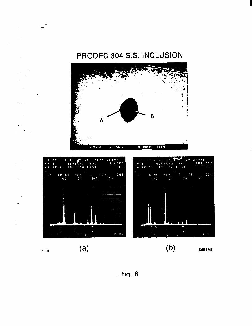
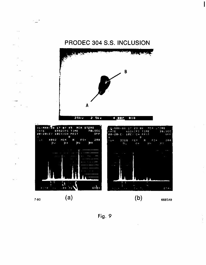
Figures 1 thru 4 show the shape and chemistry of some typical inclusions seen in the unrnodified 304 flanges. These are strung out and contain aluminum and silicon oxides and manganese sulphide. In general, the inclusions in the calcium silicide-modified 304 have the appearance shown in Figures 5 thru 9, wherein varying amounts of calcium and silicon have tied into the manganese sulphide and aluminum oxide inclusions and show a globular two phase appearance. Occasionally we find an unmodified inclusion consisting of mainly manganese sulphide (Figure 10). Chemical analysis of the Prodec plate stock is shown in Table II.
-
Brazing wettability tests performed using 50/50, 65/35 and 75/25 gold copper-alloys showed low contact angles similar to unmodified 304 S. S. when brazed in dry (-1Oppm H&j hydrogen.
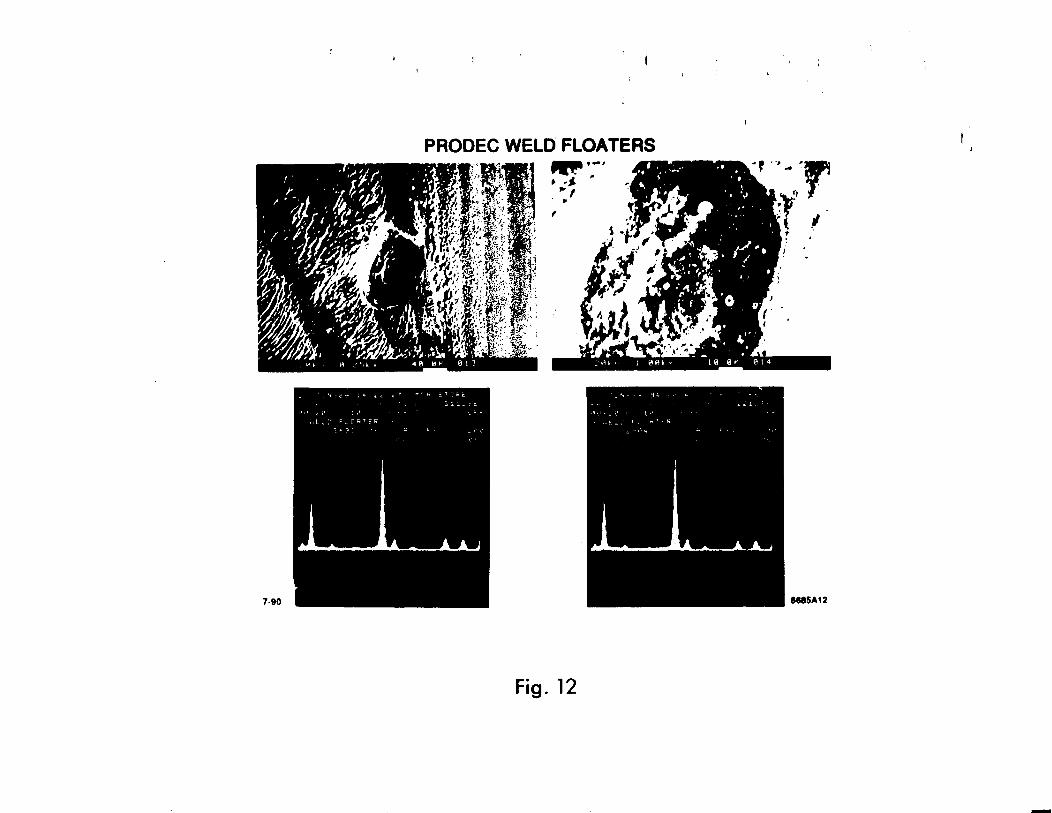
TIG fusion welds showed good weidability, and sound leak proof joints similar to unmodified 304 S. S. However, the phenomenon of “floaters” (dark eruptions) appeared as shown in Figures 11 thru 13. Analysis showed the floaters to be principally calcium silicide and sometimes, we found titanium enrichment in discrete regions, (Figure 13). Titanium is present in PRODEC at the 0.03 - 0.05% weight percent level.
Meawremene
After observing the weld floaters, we had some concern about how these might affect outgassing rates on large area welds.
We rolled up a cylinder of PRODEC plate stock ( 0.250” thick) welded it to form a tube, 6” diameter, having an internal surface area -3000 cm2 and a volume of 9.3 liters (Figure 14). The tube was cleaned using SLAC’s cleaning recipe for S.S. 171. Outgassing measurements were made by the rate of rise method. I81 The results for a variety of conditions are shown in Table III.
2

.- Thefinal low outgassing rates are comparable to literature I71 established rates for unmodified 304 S.S. It seemed to make little difference whether the welds were brushed or not.
Twelve 2.75” O.D. Conflat @) type knife edge flanges were made from PRODEC plate stock supplied by Avesta Corp. The flanges were made by MDC Corp., Hayward, CA to the same dimensions as their off-the-shelf flanges.
Prior to testing, each flange was tested for magnetic permeability, hardness and dimensional accuracy. The dimensions measured were all within the tolerances applied to knife edge flanges used by the SLAC Vacuum Department. The permeability and hardness is shown in Table IV. Two of the flanges (#l 1, & #12) were used to make a spool piece, which was mounted on a pedestal to facilitate assemby and disassembly of the test flanges. Flange #12 on one end of the spool piece was connected to a DuPont 120-SSA mass spectrometer helium leak detector. Flange #l 1 on the other end of the spool piece was the “make-up” flange for testing the remaining flanges.
-
Flanges #l through #7 were made up to and removed from flange #11 50 times with a new gasket used on each closure. A 3/8” drive air driven impact wrench was used to facilitate closure and re-opening of flange pairs. Closing force was applied to the bolts in the same rotation method as hand wrenching. Flange pairs were brought up metal-to-metal. Flanges #I through # 7 were subject to 50 closures each, and flange #1 1 was subject to 350 closures. The leak detector was calibrated at the beginning and end of each test run. The sensitivity was 3 x 10 -lo Std. cc/set/ per leak rate meter division or better. The flange pair and leak check groove were flooded with helium for 20 sec. and a 40 sec. waiting period was required for any helium response. No leak was detected on any flange pair.
-. Flange #l 1 with 350 closures was sectioned and polished for knife edge comparison with #8, an unused flange. The knife edges are shown in Figure 15. The knife edge regions are considerably harder than the base regions of the flanges. The unused knife edge measured R~93 while the flange knife edge with 350 closures measured R~98. Note the deformation of the knife edge of the flange closed 350 times.
Table IV shows hardness and permeability values for the test flanges measured near the knife edges.

.- Another flange pair, #9 and #lo, were assembled leak tested and thermally cycled between 2OO’C and liquid nitrogen for a total of 50 cycles. Helium leak testing was performed after 10,20,30,40 and 50 thermal cycles. No detectable leaks were measured.
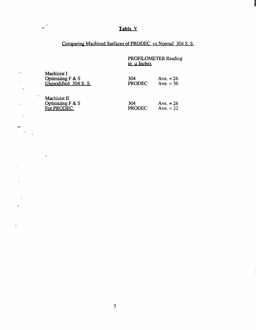
The machining tests were quite simple. Two machinists (both experienced with stainless steel ) were instructed to produce the best finish they could obtain, with both regular and PRODEC 304 S. S. using their normal tools and techniques. One was told to optimize (from their own experience) feeds and speeds for PRODEC, the other was told to optimize feeds and speeds for the normal 304 S. S. Both machinists were impressed with the easy machinability of PRODEC. The profilometer measurements for the resulting surfaces are
.- shown in Table V. . .
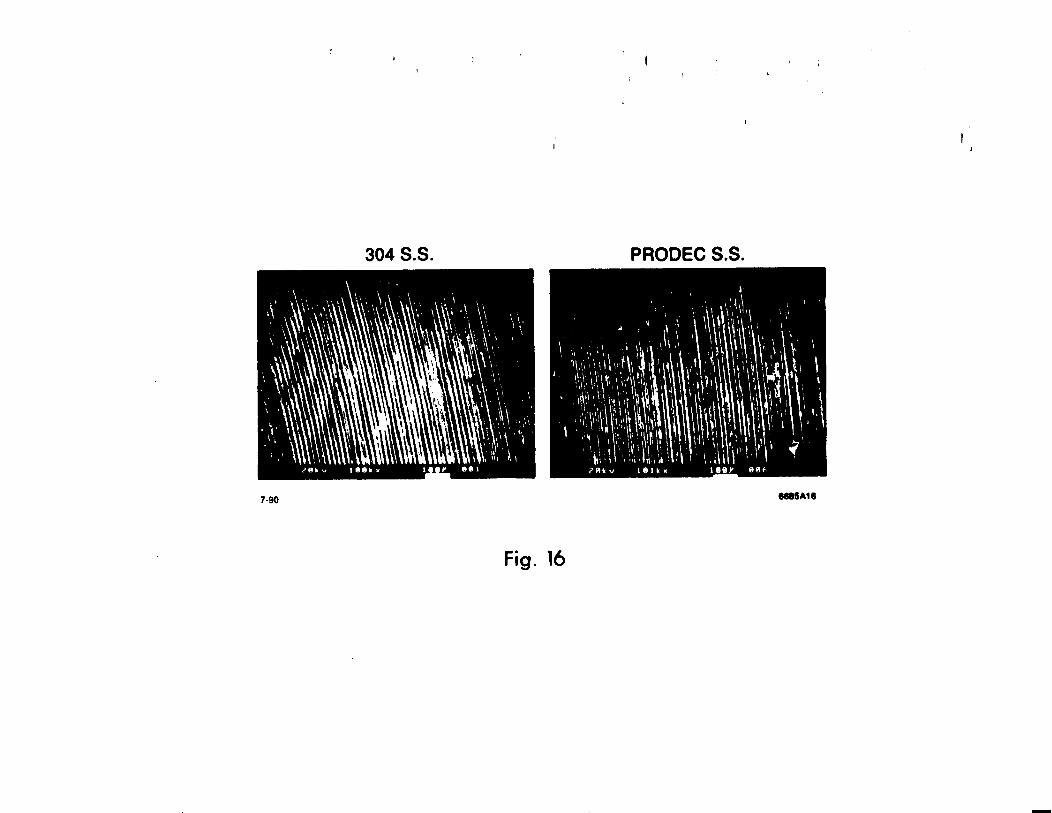
Figure 13 shows the appearance of the machined surfaces as seen magnified on the SEM. Note that these pictures support the profilometer data which shows little difference in topography, between the two types of machined surfaces.
Summary
- We have evaluated PRODEC with respect to the principal properties of interest to designers of UHV systems.
During the course of this study, we had some doubts about PRODEC being suitable for UHV applications. The increase in total inclusion value, the welding “floaters” and the lower hardness numbers raised some initial concern. However, the test results described in this report have shown that PRODEC 304 S. S. is an acceptable substitute for inclusion unmodified 304 S. S. for vacuum flanges and chambers.
One area not investigated by us relates to field emission of PRODEC surfaces exposing the modified inclusions. It is reported I91 that dielectric inclusions can enhance field emission and promote breakdown with high electric fields. For this reason we caution against using PRODEC for high field applications without further qualification.
4

Table I
Source X X X Y Y Z Prcxlec
Inclusion [*I Rating:
A-l, D2 A-l, D11/2 A-l, B1/2 B-11/2, D11/2 B-l, Dll/;!
D-3 Heavy A2Q Thin D21/2 Thin
ASTM [3] Grain Size
7
3 4 5-7 5 5 4
Rockwell 141 Magnetic [51 Hardness Permeabilitv
B87 < 1.01
B77 < 1.01
Sk1 - 1.04
B87 < 1.01
B84 < 1.01
B79 - 1.02 B84 < 1.01
Table Chemical Analysis [61 of
PRODEC Plate used in these tests
Element AI C Cr co Nb cu ml MO Ni P Si Ti V
Wt % <.005 0.037
18.91 0.13 0.005 0.32 1.06 0.27 8.46 0.022 0.033 0.008 0.07

-
PRODEC Outgassing Measurements
Tube History m
Cleaned and Pumped 30 Days Room Temp.
Held at Temp. ADays 200°C
Returned to Room Temp. Pumped 2 Days Room Temp.
Extensive Internal Welding Covering Entire Area (Figure 14).
Pumped 5 days
Heated to 200°C For 21 Days
Room Temp.
200°C
During Cooling 60°C
4 Days Later Room Temp.
Chamber vented weld areas brushed with S.S. brush and re-assembled.
Pumped 22 Days Room Temp.
Flange #
Table Rockwell Hardness
B75 B75 B75 B71.5 B77 B74 B75 B75
Outgassing Rate fTorr liter set -1 m2 )
3.8 x 10-g
5.7 x 10-g
6.9 x lo-13
9 x 10-11
1.2x IO-9
2.7 x lo-12
6.6 x 10⁻¹³
6.0 x lo-13
Permeabilitv
1.02 c p. < 1.05 1.05 <p c 1.10 1.02 <jJ < 1.05 1.02 <CL < 1.05 1.02 <p < 1.05 1.02 c p < 1.05 1.02 < p < 1.05 1.02 < p < 1.05
6
- - le V
(Comparing Machined Surfaces of PRODEC vs Normal 304 S. S.
PROFILOMETER Reading in 1 Inches
Machinist I
Machinist II
op?%%E:k ’ For
304 Ave. = 26 PRODEC Ave. = 36
304 PRODEC
Ave. = 26 Ave. = 22
IlTManufactured by Avesta, Degefors, SWEDEN. [2] ASTM E45-87 Method D. [3] ASTM Method E- 112 [4] Rockwell B ( 1/16” Ball 30 Kg) measured on flange flat 5 mm from knife edge. [5] Severin permeability indicator #1712. [6] Anamet Laboratories Inc., Hayward, CA [7] Y. Tito Sasaki, Quantum Mechanics Corp., “A Survey of Vacuum Material Cleaning Procedures” to be published in JVST. [8] AVS, 9.1 - A1.2, JVST, Nov.- Dec. (1965) p. 318. [9] R. V. Latham, “High Voltage Vacuum Insulation: The Physical Basis”, Academic Press (1981).
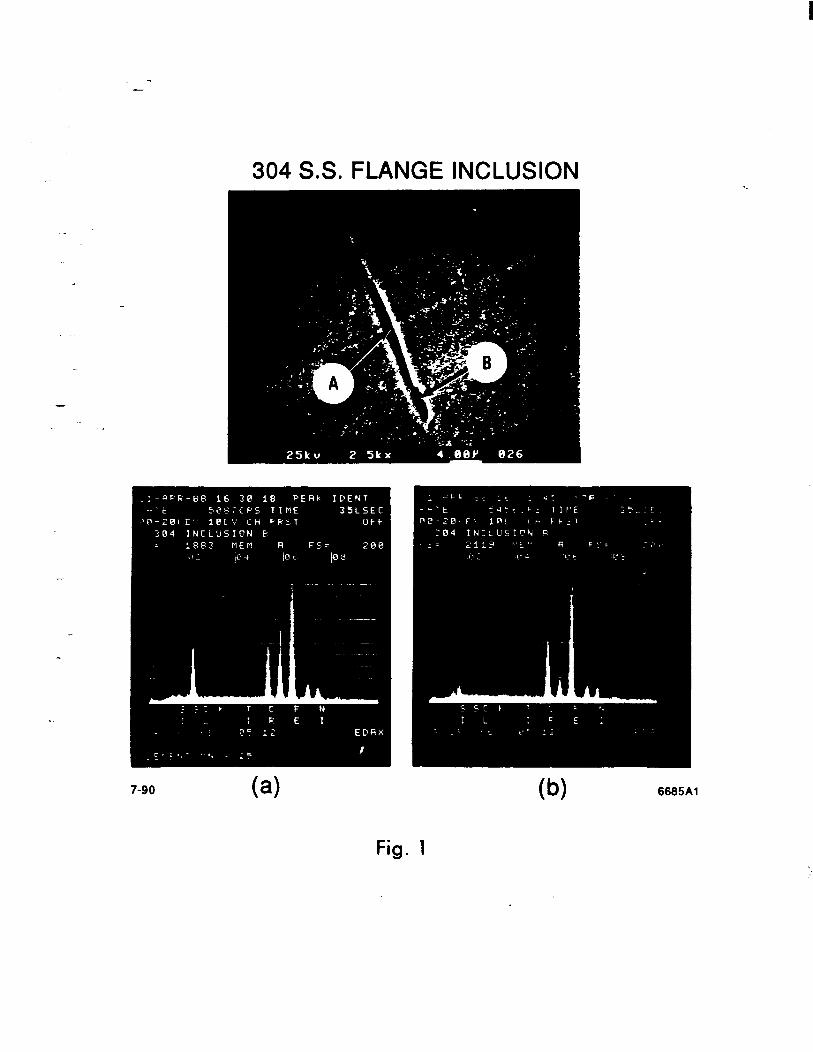
304 S.S. FLANGE INCLUSION
( ) a ( w 6665Al
rig. I

- -
304 S.S. FLANGE INCLUSION
7-90 6685A2
Fig. 2
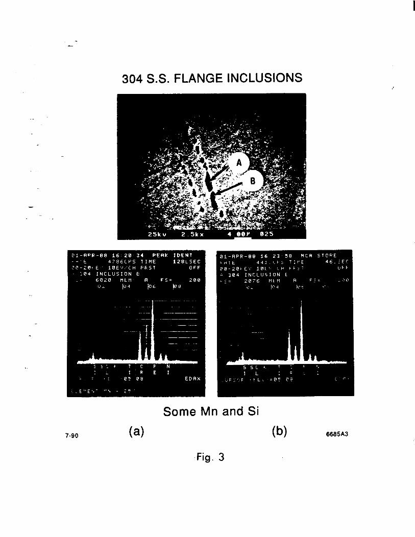
304 S.S. FLANGE INCLUSIONS
Some Mn and Si
( 1 a w 6665A3
Fig. 3
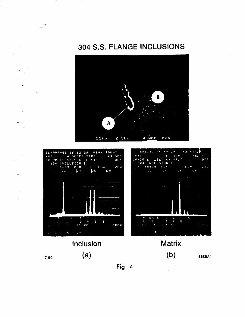
304 S.S. FLANGE INCLUSIONS
Inclusion Matrix
( 1 a @I 6665A4
ng. 4

- -
-
PRODEC 304 S.S. INCLUSION
.; . ;
Calcium Silicide+AI+S+Mg+Mn 7-90 6685A5
Fig. 5

- -
.- .
PRODEC 304 S.S. INCLUSION
7-90
Inclusion
( 1 a
Matrix
(b) 6665A6
Fig. 6

- -
PRODEC 304 S.S. INCLUSIONS
.- .
7-90 ( > a 6685A7
Fig. 7
-
PRODEC 304 S.S. INCLUSION
.- .
Fig. 8
- -
PRODEC 304 S.S. INCLUSION
.- .
7-90 ( > a ( w 6685AS

-
PRODEC 304 S.S. INCLUSIONS
-
Manganese Sulfide 7-90 6665AlO
Fig. 10

-
- -
- -
3 8

- -
06-L

- -
304 S.S. PRODEC TUBE
Showing Internal Fusion Welding to Maximize Weld Area for Outgassing Measurements
7-90 6665A14
Fig. 14

- -
100
Comparing Unused with 350 Closure Knife Edges of PRODEC Flanges
X
(a) Unused
X
(b) Following 350 Closures 7-90 6665A15
Fig. 15
- - -

I